Embed Size (px)
Citation preview
Version
0.1
0.2
0.3
1.0
1.1
1.2
Alarm Handling Subsystem (AHS) Requirements
Specification
Enterprise Building Management System (EBMS)
DOCUMENT HISTORY
Description
DRAFT
Delete references to alarms being created in Server. Specification modified to require alarms to be
created at lowest possible Niagara device.
Issued for approval.
Changes requested by MUP incorporated.
Minor Changes
For Circulation
Alarm Handling Subsystem (AHS) Requirements
Enterprise Building Management System (EBMS)
Date issued
5/10/2012
13/2/2013
26/2/2013
11/03/2013
12/04/2013
March 2016
Alarm Handling Subsystem (AHS) Requirements
Enterprise Building Management System (EBMS)

Alarm Handling Subsystem (AHS) Requirements Specification
Name Position
Dennis Spicer Engineering Project Manager
David Matley Technical Services Manager
Alarm Handling Subsystem (AHS) Requirements Specification
CIRCULATION APPROVAL
Approved
Engineering Project Manager
Technical Services Manager
Revision Control
Approved
Alarm Handling Subsystem (AHS) Requirements Specification
MUP Enterprise Building Management System (EBMS)
TABLE OF CONTENTS
1.0 PURPOSE
2.0 SCOPE
3.0 REFERENCES AND STAND
4.0 DESIGN CONSIDERATION
4.1 ASSUMPTIONS
4.2 CONSTRAINTS
4.3 DEPENDENCIES
5.0 DEFINITIONS AND ABBR
6.0 GENERAL REQUIREMENTS
7.0 FUNCTIONAL REQUIREME
7.1 USERS AND ROLES
7.2 PLANT GROUPS
7.3 ALARM TYPES
7.4 ALARM RECORD FORMAT
7.5 ALARM CLASSES
7.6 ALARM WORKFLOW GENERAL
7.7 AX SUPERVISOR ALARM WORKFLOW CONFIGURATION
APPENDIX A
APPENDIX B
Alarm Handling Subsystem (AHS) Requirements Specification
TABLE OF CONTENTS
REFERENCES AND STANDARDS
DESIGN CONSIDERATIONS
DEFINITIONS AND ABBREVIATIONS
GENERAL REQUIREMENTS
FUNCTIONAL REQUIREMENTS
ALARM RECORD FORMAT
ALARM WORKFLOW GENERAL
AX SUPERVISOR ALARM WORKFLOW CONFIGURATION
Table of Contents
1
2
3
4
5
5
5
5
6
8
9
9
9
10
10
11
12
12
15
16
Alarm Handling Subsystem (AHS) Requirements Specification
MUP Alarm Subsystem Specification Design Standard_V1.1
1.0 PURPOSE
The purpose of this document is to describe
defines how alarms are generated and handled
number of alarms required to communicate
The Alarm Handling Sub-System is part of the Campus EBMS AX Supervisor. T
read in conjunction with the “Guideline Design Standard for Building Management Sy
Alarm Handling Subsystem (AHS) Requirements Specification
Design Standard_V1.1
The purpose of this document is to describe the campus wide Alarm Handling S
defines how alarms are generated and handled to limit the alarms generated
to communicate critical and maintenance conditions.
System is part of the Campus EBMS AX Supervisor. This document should be
read in conjunction with the “Guideline Design Standard for Building Management Sy
Purpose
2
Handling Sub system and
generated to the minimum
is document should be
read in conjunction with the “Guideline Design Standard for Building Management Systems (BMS)”.
Alarm Handling Subsystem (AHS) Requirements Specification
MUP Alarm Subsystem Specification Design Standard_V1.1
2.0 SCOPE
This Specification covers all alarms generated
VARIOUS stake holders via the campus wide EBMS (AX Supervisor).
Alarm Handling Subsystem (AHS) Requirements Specification
Design Standard_V1.1
This Specification covers all alarms generated by any BMS’s on campus and the distribution of alarms to
VARIOUS stake holders via the campus wide EBMS (AX Supervisor).
Scope
3
by any BMS’s on campus and the distribution of alarms to
Alarm Handling Subsystem (AHS) Requirements Specification
MUP Alarm Subsystem Specification Design Standard_V1.1
3.0 REFERENCES AND STAND
� Macquarie University
Version 2.00
� National Institute of Standards and Technology (NIST). GSA Guide to Specifying Interoperable
Building Automation and Control Systems Using ANSI/ASHRAE Standard 135
� American Society of Heating Refrigeration and Air
Implementation Conformance Statement)
� NiagaraAX Platform Guide
Alarm Handling Subsystem (AHS) Requirements Specification
Design Standard_V1.1
REFERENCES AND STANDARDS
Macquarie University, Sydney. Guideline Design Standard for Building Management Systems (BMS)
National Institute of Standards and Technology (NIST). GSA Guide to Specifying Interoperable
Building Automation and Control Systems Using ANSI/ASHRAE Standard 135
American Society of Heating Refrigeration and Air-conditioning Engineers.
Implementation Conformance Statement)
Platform Guide
References and Standards
4
Guideline Design Standard for Building Management Systems (BMS)
National Institute of Standards and Technology (NIST). GSA Guide to Specifying Interoperable
Building Automation and Control Systems Using ANSI/ASHRAE Standard 135-1995, BACnet
conditioning Engineers. BACnet PICs (protocol
Alarm Handling Subsystem (AHS) Requirements Specification
MUP Alarm Subsystem Specification Design Standard_V1.1
4.0 DESIGN CONSIDERATION
4.1 ASSUMPTIONS
The alarm handling sub-system shall interface to (and be integrated with) the existing EBMS AX Supervisor
alarm subsystem. For legacy syste
framework) will be used to interface to the existing AX Supervisor.
4.2 CONSTRAINTS
Many of the systems report alarms on a point by point bases, where no consideration has been given to
consolidating the alarms in to one event or to reduce the nuisance alarm flooding that occurs during a major
failure i.e. equipment losing control during a fire trip.
4.3 DEPENDENCIES
Alarm reporting depends on a fully functional campus wide area networ
from the building controllers.
Alarm processing and distribution is via the AX Supervisor.
Alarm Handling Subsystem (AHS) Requirements Specification
Design Standard_V1.1
DESIGN CONSIDERATIONS
system shall interface to (and be integrated with) the existing EBMS AX Supervisor
alarm subsystem. For legacy systems if a compatible interface does not exist, a JACE (running Niagara
framework) will be used to interface to the existing AX Supervisor.
Many of the systems report alarms on a point by point bases, where no consideration has been given to
consolidating the alarms in to one event or to reduce the nuisance alarm flooding that occurs during a major
failure i.e. equipment losing control during a fire trip.
Alarm reporting depends on a fully functional campus wide area network. No backup or secondary paths exist
from the building controllers.
Alarm processing and distribution is via the AX Supervisor.
Design Considerations
5
system shall interface to (and be integrated with) the existing EBMS AX Supervisor
ms if a compatible interface does not exist, a JACE (running Niagara
Many of the systems report alarms on a point by point bases, where no consideration has been given to either
consolidating the alarms in to one event or to reduce the nuisance alarm flooding that occurs during a major
k. No backup or secondary paths exist
Alarm Handling Subsystem (AHS) Requirements Specification
MUP Alarm Subsystem Specification Design Standard_V1.1
5.0 DEFINITIONS AND ABBR
ACU, Air Conditioning Unit
AHU, Air Handling Unit
AI, Analog Input a value that can be read from
Alarm, An event that must be acknowledged by an user (i.e. a Critical or Maintenance alarm). As distinct from
an event that is logged to the archive for future reference
Alarm Class, A method of grouping classifying alarms to simply handling
Alarm Handling Subsystem (AHS),
link to each building.
AO, Analog Output, value that be read from a controller and written to by software
AV, Analog Value, a holding variable
AX Supervisor, The main EBMS software and server used to interface to all campus building control systems.
BACnet, Interoperability protocol
BACnet Advanced Application Controller (BACnet AAC)
BACnet Application Specific Controller (BACnet ASC)
BACnet Building Controller (B
BACnet Operator Workstation (B
BACnet Advanced Workstation (B
BCS, Building Control Station, a high level BMS controller typically connected directly to the MACQUARIE
UNIVERSITY WAN. Commonly used to control chillers, large Air handling systems and othe
equipment. Must conform to BACnet B
BI, Binary Input, a digital value read from a controller
BMS, Building Management System, A control and management system installed at a building level.
BV, Binary Value, a digital holding va
DSC, Distributed Control System
DMZ, Demilitarized Zone
EBMS, Enterprise Building Management Server, Enterprise wide server interfacing individual Building
Management Systems.
Event, A change of state captured by alarm management software either at
be logged for future reference or may be an alarm.
FCU, Fan Coil Unit
Alarm Handling Subsystem (AHS) Requirements Specification Definitions
Design Standard_V1.1
DEFINITIONS AND ABBREVIATIONS
Analog Input a value that can be read from a controller
An event that must be acknowledged by an user (i.e. a Critical or Maintenance alarm). As distinct from
an event that is logged to the archive for future reference
A method of grouping classifying alarms to simply handling of alarms.
Alarm Handling Subsystem (AHS), The alarm handling subsystem including the EBMS Server and Campus WAN
Analog Output, value that be read from a controller and written to by software
ing variable such as a setpoint
The main EBMS software and server used to interface to all campus building control systems.
Interoperability protocol ISO 16484-5
BACnet Advanced Application Controller (BACnet AAC), application controller
Application Specific Controller (BACnet ASC), application controller for VAV, FCU etc.
BACnet Building Controller (B-BC), controller device profile for high level network based controllers.
BACnet Operator Workstation (B-OWS), network level workstation
Cnet Advanced Workstation (B-AWS), advanced operator workstation
Building Control Station, a high level BMS controller typically connected directly to the MACQUARIE
UNIVERSITY WAN. Commonly used to control chillers, large Air handling systems and othe
equipment. Must conform to BACnet B-BC device profile.
Binary Input, a digital value read from a controller
Building Management System, A control and management system installed at a building level.
Binary Value, a digital holding variable
Distributed Control System
Enterprise Building Management Server, Enterprise wide server interfacing individual Building
A change of state captured by alarm management software either at BMS or EBMS level. An event may
be logged for future reference or may be an alarm.
Definitions and Abbreviations
6
An event that must be acknowledged by an user (i.e. a Critical or Maintenance alarm). As distinct from
of alarms.
The alarm handling subsystem including the EBMS Server and Campus WAN
Analog Output, value that be read from a controller and written to by software
The main EBMS software and server used to interface to all campus building control systems.
application controller for VAV, FCU etc.
controller device profile for high level network based controllers.
Building Control Station, a high level BMS controller typically connected directly to the MACQUARIE
UNIVERSITY WAN. Commonly used to control chillers, large Air handling systems and other complex
Building Management System, A control and management system installed at a building level.
Enterprise Building Management Server, Enterprise wide server interfacing individual Building
BMS or EBMS level. An event may
Alarm Handling Subsystem (AHS) Requirements Specification
MUP Alarm Subsystem Specification Design Standard_V1.1
JACE, Java Control Engine, Application controller manufactured by Tridium Inc.
LDAP, Lightweight Directory Access Protocol
Lonworks, Echelon Corporation
Modbus/RTU, Modbus over serial link (RS
Modbus/TCP, Modbus over IP (Transmission Control Protocol)
Native BACnet system, a system that can be proven to be designed around the BACnet standard. Excludes
systems that provide BACnet gateways or BACnet integration at only the LAN level. Native BACnet should
support a majority of BACnet objects including but not limited to Points, Services, Alarms, Time Schedules,
Trendlogs and Programs.
NMS, Network Management System, a software
NTP, Network Time Protocol
OFM, Office of Facilities Management
RDC, Remote Distributed Controller, BACnet application oriented controllers, typically linked to a BCS or a
BACnet router for supervisory functionality,
provide VAV, FCU, small AHU, and Packaged Equipment local control. Required to support B
profile.
RDP, Remote Desktop Protocol (multi
Services).
SDD, System Design Document, includes all design information for approval prior to installation
SNMP, Simple Network Management Protocol
SMTP, Simple Mail Transfer Protocol
VAV, Variable Air Volume (referencing the controller/
VPN, Virtual Private Network
UTC, Coordinated Universal Time
Alarm Handling Subsystem (AHS) Requirements Specification Definitions
Design Standard_V1.1
Java Control Engine, Application controller manufactured by Tridium Inc.
Lightweight Directory Access Protocol
, Echelon Corporation Lonworks network standard
Modbus over serial link (RS-485)
, Modbus over IP (Transmission Control Protocol)
a system that can be proven to be designed around the BACnet standard. Excludes
net gateways or BACnet integration at only the LAN level. Native BACnet should
support a majority of BACnet objects including but not limited to Points, Services, Alarms, Time Schedules,
Network Management System, a software system for monitoring network devices.
Office of Facilities Management
Remote Distributed Controller, BACnet application oriented controllers, typically linked to a BCS or a
BACnet router for supervisory functionality, may reside on a lower speed (78Kbs) peer to peer LAN. Commonly
provide VAV, FCU, small AHU, and Packaged Equipment local control. Required to support B
Remote Desktop Protocol (multi-channel allowing remote clients to connect to
System Design Document, includes all design information for approval prior to installation
Simple Network Management Protocol
Simple Mail Transfer Protocol
Variable Air Volume (referencing the controller/actuator)
Virtual Private Network
Coordinated Universal Time
Definitions and Abbreviations
7
a system that can be proven to be designed around the BACnet standard. Excludes
net gateways or BACnet integration at only the LAN level. Native BACnet should
support a majority of BACnet objects including but not limited to Points, Services, Alarms, Time Schedules,
system for monitoring network devices.
Remote Distributed Controller, BACnet application oriented controllers, typically linked to a BCS or a
may reside on a lower speed (78Kbs) peer to peer LAN. Commonly
provide VAV, FCU, small AHU, and Packaged Equipment local control. Required to support B-AAC or B-ASC
channel allowing remote clients to connect to Microsoft Terminal
System Design Document, includes all design information for approval prior to installation
Alarm Handling Subsystem (AHS) Requirements Specification
MUP Alarm Subsystem Specification Design Standard_V1.1
6.0 GENERAL REQUIREMENTS
� Deliver alarms to the end user or users so the
� The maintainer of the EBMS server is responsible for the delivery of
to graphics, email, SMS, SNMP or other delivery mechanism. Individual building BMS systems will
not transmit alarms directly to users, except with the express agreement of MU Property and the
EBMS Maintainer. This requirement
alarm flooding, missed alarms, or incorrectly programmed alarms.
� The central alarm handling system is required to achieve Total Availability of T(av) = 0.996. This
implies a maximum annual downtime
server and Campus network outages.
� To ensure that alarms for critical equipment such as fridges and freezers are transmitted to the
Service Desk reliably, the Mean Time to Repair (MTTR) of the Ser
maintenance shall be no greater than 8 hours. Combined with the availability requirement, no
more than 4 outages of 8 hours duration are permitted in each 12 month period.
� Alarms will be created at the Building Level (the neare
communications to the server) and will be sent to the EBMS server using the Station recipient
mechanism. This capability shall enable:
- Standalone operation with a standalone server where the building is required to
display alarms locally from a local server
- Where speed of response is critical (such as capture of fleeting alarms from electrical
measurements or other local processes)
- Where complex alarm logic produces a derived output state that is time critical (
preferred that the output state is sent to the EBMS server for alarm processing)
� The EBMS shall be able to manage (including acknowledgement) all alarms in accordance with the
BACnet AWS profile.
� The EBMS will provide alarm monitoring of
� Alarms that have been acknowledged and returned to normal shall be removed from the visible
display and moved to the archive. At any time the user shall be able to view the archive by a simple
selection from the current alarm disp
or software.
� The alarm management system shall be capable of processing at least 1,000 events per day at the
EBMS Server with less than 1% error. The alarm management system must be able to p
least 250 alarms per day to the users with less than 1% failure rate.
� A link from any alarm to a context relevant graphic shall be provided at the EBMS server There will
be no graphics stored in the BMS in the field other than those required for
backup. All alarm to graphics links shall be created solely for graphics and alarms stored at the
EBMS server level.
� As well as being able to receive alarms from BACnet systems, it shall be possible to program alarms
at the EBMS for any point imported to the EBMS.
� At any time it shall be possible to produce a report of all points in alarm, all alarms suppressed and
an all alarms history.
� The EBMS will provide for each building to have its own separate alarm queuing and handling,
allowing for display of alarms on each buildings graphical web page.
� BCS time clock’s
Time Protocol and
Alarm Handling Subsystem (AHS) Requirements Specification
Design Standard_V1.1
GENERAL REQUIREMENTS
Deliver alarms to the end user or users so the appropriate actions can be taken or scheduled.
The maintainer of the EBMS server is responsible for the delivery of
to graphics, email, SMS, SNMP or other delivery mechanism. Individual building BMS systems will
not transmit alarms directly to users, except with the express agreement of MU Property and the
EBMS Maintainer. This requirement is to ensure that alarms are centrally managed to prevent
alarm flooding, missed alarms, or incorrectly programmed alarms.
The central alarm handling system is required to achieve Total Availability of T(av) = 0.996. This
implies a maximum annual downtime of approximately 32 hours including routine maintenance of
server and Campus network outages.
To ensure that alarms for critical equipment such as fridges and freezers are transmitted to the
Service Desk reliably, the Mean Time to Repair (MTTR) of the Ser
maintenance shall be no greater than 8 hours. Combined with the availability requirement, no
more than 4 outages of 8 hours duration are permitted in each 12 month period.
Alarms will be created at the Building Level (the nearest Niagara device in the chain of
communications to the server) and will be sent to the EBMS server using the Station recipient
mechanism. This capability shall enable:
Standalone operation with a standalone server where the building is required to
display alarms locally from a local server
Where speed of response is critical (such as capture of fleeting alarms from electrical
measurements or other local processes)
Where complex alarm logic produces a derived output state that is time critical (
preferred that the output state is sent to the EBMS server for alarm processing)
The EBMS shall be able to manage (including acknowledgement) all alarms in accordance with the
AWS profile.
The EBMS will provide alarm monitoring of all building services.
Alarms that have been acknowledged and returned to normal shall be removed from the visible
display and moved to the archive. At any time the user shall be able to view the archive by a simple
selection from the current alarm display. This function shall not require any special reporting tools
The alarm management system shall be capable of processing at least 1,000 events per day at the
EBMS Server with less than 1% error. The alarm management system must be able to p
least 250 alarms per day to the users with less than 1% failure rate.
A link from any alarm to a context relevant graphic shall be provided at the EBMS server There will
be no graphics stored in the BMS in the field other than those required for
backup. All alarm to graphics links shall be created solely for graphics and alarms stored at the
EBMS server level.
As well as being able to receive alarms from BACnet systems, it shall be possible to program alarms
any point imported to the EBMS.
At any time it shall be possible to produce a report of all points in alarm, all alarms suppressed and
an all alarms history.
The EBMS will provide for each building to have its own separate alarm queuing and handling,
wing for display of alarms on each buildings graphical web page.
’s must be able to synchronise with Macquarie University
and local alarm buffering for up 500 alarms offline from the server.
General Requirements
8
actions can be taken or scheduled.
alarms to the users, whether
to graphics, email, SMS, SNMP or other delivery mechanism. Individual building BMS systems will
not transmit alarms directly to users, except with the express agreement of MU Property and the
is to ensure that alarms are centrally managed to prevent
The central alarm handling system is required to achieve Total Availability of T(av) = 0.996. This
of approximately 32 hours including routine maintenance of
To ensure that alarms for critical equipment such as fridges and freezers are transmitted to the
Service Desk reliably, the Mean Time to Repair (MTTR) of the Server after a fault or routine
maintenance shall be no greater than 8 hours. Combined with the availability requirement, no
more than 4 outages of 8 hours duration are permitted in each 12 month period.
st Niagara device in the chain of
communications to the server) and will be sent to the EBMS server using the Station recipient
Standalone operation with a standalone server where the building is required to process and
Where speed of response is critical (such as capture of fleeting alarms from electrical
Where complex alarm logic produces a derived output state that is time critical (although it is
preferred that the output state is sent to the EBMS server for alarm processing)
The EBMS shall be able to manage (including acknowledgement) all alarms in accordance with the
Alarms that have been acknowledged and returned to normal shall be removed from the visible
display and moved to the archive. At any time the user shall be able to view the archive by a simple
lay. This function shall not require any special reporting tools
The alarm management system shall be capable of processing at least 1,000 events per day at the
EBMS Server with less than 1% error. The alarm management system must be able to present at
A link from any alarm to a context relevant graphic shall be provided at the EBMS server There will
be no graphics stored in the BMS in the field other than those required for critical maintenance or
backup. All alarm to graphics links shall be created solely for graphics and alarms stored at the
As well as being able to receive alarms from BACnet systems, it shall be possible to program alarms
At any time it shall be possible to produce a report of all points in alarm, all alarms suppressed and
The EBMS will provide for each building to have its own separate alarm queuing and handling,
Macquarie University Time Server (Network
local alarm buffering for up 500 alarms offline from the server.

Alarm Handling Subsystem (AHS) Requirements Specification
MUP Alarm Subsystem Specification Design Standard_V1.1
7.0 FUNCTIONAL REQUI
7.1 USERS AND ROLES
Macquarie University has four (4) main stakeholders groups that are responsible to monitor and act on
alarms events.
The Alarm Handling System shall have the ability to define Users and allocate roles to the user based on the
functions required by their roles. Where a role is defined it shall be possible to create new users and assign
these users to the selected role.
The User Groups currently accommodated by the Alarm Handling system are:
7.1.1 Macquarie Property Staff
Macquarie Property Staff are responsible for:
� Maintaining building environmental conditions
� Maintaining the campus building and plant equipment.
7.1.2 Security Staff
Security staff are responsible for:
� Responding to and reporting alarms 24 hours per day, 7 days per week,
responsible Macquarie Property Staff to attend to critical alarms.
7.1.3 Facilities Staff (including facility operators and department staff)
Staff are responsible for:
� The environmental conditions in selected laboratories, or facilities suc
� Responding to alarms on selected equipment (i.e. fridges, freezers, etc.).
� Allocating service and repair contractors as required and authorised.
7.1.4 Contractors and consultants
Contractors and consultants are responsible for:
� Providing and / or maintaining compliant building systems, mechanical or electrical plant to this
Specification.
7.2 PLANT GROUPS
Plant groups shall be used to define the following:
� Each plant group shall be defined such that users are assigned permissions to the plant grou
which they have access rights within the BMS.
� Plant groups can be defined to be complete buildings, or campus wide systems, such as Cogen,
District Cooling, External Lighting or similar.
� Any valid user will have READ ONLY permission for all Plant Gr
� Users shall be granted specific WRITE or INITIATE permission only to assigned Plant Groups. For
example, it shall be possible to grant WRITE access to staff in the pool to change room setpoints
within the pool facility, however pool staff shall not ha
buildings.
� It shall be possible to assign users to more than one Plant Group.
Alarm Handling Subsystem (AHS) Requirements Specification
Design Standard_V1.1
FUNCTIONAL REQUIREMENTS
Macquarie University has four (4) main stakeholders groups that are responsible to monitor and act on
The Alarm Handling System shall have the ability to define Users and allocate roles to the user based on the
nctions required by their roles. Where a role is defined it shall be possible to create new users and assign
these users to the selected role.
The User Groups currently accommodated by the Alarm Handling system are:
Macquarie Property Staff
rty Staff are responsible for:
Maintaining building environmental conditions
Maintaining the campus building and plant equipment.
Security staff are responsible for:
Responding to and reporting alarms 24 hours per day, 7 days per week,
responsible Macquarie Property Staff to attend to critical alarms.
(including facility operators and department staff)
The environmental conditions in selected laboratories, or facilities suc
Responding to alarms on selected equipment (i.e. fridges, freezers, etc.).
Allocating service and repair contractors as required and authorised.
Contractors and consultants
Contractors and consultants are responsible for:
/ or maintaining compliant building systems, mechanical or electrical plant to this
Plant groups shall be used to define the following:
Each plant group shall be defined such that users are assigned permissions to the plant grou
which they have access rights within the BMS.
Plant groups can be defined to be complete buildings, or campus wide systems, such as Cogen,
District Cooling, External Lighting or similar.
Any valid user will have READ ONLY permission for all Plant Groups
Users shall be granted specific WRITE or INITIATE permission only to assigned Plant Groups. For
example, it shall be possible to grant WRITE access to staff in the pool to change room setpoints
within the pool facility, however pool staff shall not have access to change setpoints in other
It shall be possible to assign users to more than one Plant Group.
Functional Requirements
9
Macquarie University has four (4) main stakeholders groups that are responsible to monitor and act on the
The Alarm Handling System shall have the ability to define Users and allocate roles to the user based on the
nctions required by their roles. Where a role is defined it shall be possible to create new users and assign
Responding to and reporting alarms 24 hours per day, 7 days per week, including contacting
(including facility operators and department staff)
The environmental conditions in selected laboratories, or facilities such as swimming pool.
Responding to alarms on selected equipment (i.e. fridges, freezers, etc.).
/ or maintaining compliant building systems, mechanical or electrical plant to this
Each plant group shall be defined such that users are assigned permissions to the plant groups for
Plant groups can be defined to be complete buildings, or campus wide systems, such as Cogen,
Users shall be granted specific WRITE or INITIATE permission only to assigned Plant Groups. For
example, it shall be possible to grant WRITE access to staff in the pool to change room setpoints
ve access to change setpoints in other
Alarm Handling Subsystem (AHS) Requirements Specification
MUP Alarm Subsystem Specification Design Standard_V1.1
7.3 ALARM TYPES
Alarm types shall be defined and setup as follows:
� Alarm conditions are programmed in each building’s BMS. Alarms shall be clas
requirements of this Specification.
� The BMS System shall generate the appropriate alarm on detection of a fault or out of limit
quantity.
The BMS shall be capable of generating alarms of the following types:
� Failure of any controller or c
� Failure of communications between the EBMS and the BMS controllers or controller networks
� Discrepancy between required output and measured response
� Set Boolean or Analog thresholds.
� Deviation from setpoint (where programmed).
The following general requirements apply to alarm events generated by the BMS:
� Critical alarms must be able to be received at the EBMS server within 10 seconds of occurrence.
� Where more than one alarm event can be generated from a single failure or out of spe
condition (i.e. fire trip), one alarm event will be generated as the notification event and all other
associated alarms should be at a lower priority or suppressed so that the alarm system is not
flooded with nuisance alarms.
� The generation of e
suppressed when the controlled plant is not operating.
� Where quantities can vary as part of a process, suitable
alarms are not generated.
� Suitable user adjustable time delays shall be assigned (to both on and off transitions) as well as
alarm thresholds (low limit, low level, high level, high limit) and deadbands to prevent nuisance
alarms and alarm flooding.
� Any alarm shall be able to be suppr
EBMS during periods of maintenance or repair of faulty equipment.
� It shall be possible for an adjustable time delay to be added to return the alarm to normal function
without user intervention.
� Critical alarms are to be individually programmed with instructions, contact details and phone
numbers provided within the alarm message.
In addition to handling and distributing alarms received form the BMS the EBMS shall be capable of
generating the following alarms:
� Software failure within the EBMS
� Failure of communications between the EBMS and the BMS controllers or controller networks
7.4 ALARM RECORD FORMAT
All alarms are to have the same format and provide the following information at a minimum.
� Each alarm point is to be based on the Point Naming Convention (location and equipment type)
Refer Macquarie University object naming methodology.
� Type of alarm condition (High Level, High Limit etc).
� Occurrence date and time.
� Return date and time.
Alarm Handling Subsystem (AHS) Requirements Specification
Design Standard_V1.1
Alarm types shall be defined and setup as follows:
Alarm conditions are programmed in each building’s BMS. Alarms shall be clas
requirements of this Specification.
The BMS System shall generate the appropriate alarm on detection of a fault or out of limit
The BMS shall be capable of generating alarms of the following types:
Failure of any controller or component of the BMS System
Failure of communications between the EBMS and the BMS controllers or controller networks
Discrepancy between required output and measured response
Set Boolean or Analog thresholds.
Deviation from setpoint (where programmed).
following general requirements apply to alarm events generated by the BMS:
Critical alarms must be able to be received at the EBMS server within 10 seconds of occurrence.
Where more than one alarm event can be generated from a single failure or out of spe
condition (i.e. fire trip), one alarm event will be generated as the notification event and all other
associated alarms should be at a lower priority or suppressed so that the alarm system is not
flooded with nuisance alarms.
The generation of environmental out of limits alarms must be programmed such that they are
suppressed when the controlled plant is not operating.
Where quantities can vary as part of a process, suitable hysteresis will be used to ensure nuisance
alarms are not generated.
table user adjustable time delays shall be assigned (to both on and off transitions) as well as
alarm thresholds (low limit, low level, high level, high limit) and deadbands to prevent nuisance
alarms and alarm flooding.
Any alarm shall be able to be suppressed temporarily such that no further alarms are sent to the
EBMS during periods of maintenance or repair of faulty equipment.
It shall be possible for an adjustable time delay to be added to return the alarm to normal function
without user intervention.
Critical alarms are to be individually programmed with instructions, contact details and phone
numbers provided within the alarm message.
In addition to handling and distributing alarms received form the BMS the EBMS shall be capable of
owing alarms:
Software failure within the EBMS
Failure of communications between the EBMS and the BMS controllers or controller networks
FORMAT
All alarms are to have the same format and provide the following information at a minimum.
rm point is to be based on the Point Naming Convention (location and equipment type)
Refer Macquarie University object naming methodology.
Type of alarm condition (High Level, High Limit etc).
Occurrence date and time.
Return date and time.
Functional Requirements
10
Alarm conditions are programmed in each building’s BMS. Alarms shall be classified as per the
The BMS System shall generate the appropriate alarm on detection of a fault or out of limit
Failure of communications between the EBMS and the BMS controllers or controller networks
Critical alarms must be able to be received at the EBMS server within 10 seconds of occurrence.
Where more than one alarm event can be generated from a single failure or out of specification
condition (i.e. fire trip), one alarm event will be generated as the notification event and all other
associated alarms should be at a lower priority or suppressed so that the alarm system is not
nvironmental out of limits alarms must be programmed such that they are
will be used to ensure nuisance
table user adjustable time delays shall be assigned (to both on and off transitions) as well as
alarm thresholds (low limit, low level, high level, high limit) and deadbands to prevent nuisance
essed temporarily such that no further alarms are sent to the
It shall be possible for an adjustable time delay to be added to return the alarm to normal function
Critical alarms are to be individually programmed with instructions, contact details and phone
In addition to handling and distributing alarms received form the BMS the EBMS shall be capable of
Failure of communications between the EBMS and the BMS controllers or controller networks
All alarms are to have the same format and provide the following information at a minimum.
rm point is to be based on the Point Naming Convention (location and equipment type)
Alarm Handling Subsystem (AHS) Requirements Specification
MUP Alarm Subsystem Specification Design Standard_V1.1
� Acknowledge dat
� Value of the point at the time of alarm occurrence.
� All alarms will be logged to permanent storage
� Default alarm shall not be logged at the EBMS during system testing.
7.5 ALARM CLASSES
Alarms shall be grouped by their impo
7.5.1 Critical Alarm
Alarms that need immediate attention
� HVAC
� Electrical
� Fire
� Hydraulic
� Other
7.5.2 Maintenance Alarm
Alarms that do not need immediate attention
Maintenance Alarm classes will be grouped by building service type:
� HVAC
� Electrical
� Fire
� Hydraulic
� Other
7.5.3 Information Alarm
Events that require an alarm to be
(ie Faculty personnel) or other reasons.
7.5.4 Niagara Network Health
Niagara Network Health alarm class is reserved exclusively for Network Offline alarms only.
7.5.5 Default Alarm Class
The Default Alarm Class exists within the B
to the building BMS. The purpose of the
for commissioning or testing purposes witho
by the EBMS.
7.5.6 Alarm Class Naming Convention
Alarm Classes shall be named using the format:
7.5.6.1 Building Number Priority Building
For example building E8A Critical HVAC alarm class shall
Alarm Handling Subsystem (AHS) Requirements Specification
Design Standard_V1.1
Acknowledge date, time and operator identification.
Value of the point at the time of alarm occurrence.
All alarms will be logged to permanent storage
Default alarm shall not be logged at the EBMS during system testing.
Alarms shall be grouped by their importance and type. The following generic Alarm Classes shall be defined:
Alarms that need immediate attention. Critical alarm classes will be grouped by building service type:
do not need immediate attention but are required to be visible via an Alarm Console graphic.
Maintenance Alarm classes will be grouped by building service type:
Events that require an alarm to be captured at the AX Supervisor for information only to used by MUP clients
(ie Faculty personnel) or other reasons.
Health
Niagara Network Health alarm class is reserved exclusively for Network Offline alarms only.
efault Alarm Class exists within the B-BC (typically a Niagara JACE) only and
to the building BMS. The purpose of the DefaultAlarmClass is to allow BMS Contractors to programme alarms
for commissioning or testing purposes without confusing MUP personnel by having these alarms being received
Alarm Class Naming Convention
Alarm Classes shall be named using the format:
Building Service.
Critical HVAC alarm class shall be “E8A_Critical_HVAC”. No spaces shall be allowed.
Functional Requirements
11
rtance and type. The following generic Alarm Classes shall be defined:
. Critical alarm classes will be grouped by building service type:
but are required to be visible via an Alarm Console graphic.
captured at the AX Supervisor for information only to used by MUP clients
Niagara Network Health alarm class is reserved exclusively for Network Offline alarms only.
BC (typically a Niagara JACE) only and shall not be routed external
is to allow BMS Contractors to programme alarms
ut confusing MUP personnel by having these alarms being received
be “E8A_Critical_HVAC”. No spaces shall be allowed.
Alarm Handling Subsystem (AHS) Requirements Specification
MUP Alarm Subsystem Specification Design Standard_V1.1
7.5.7 Ad Hoc Alarm Classes
Additional alarm classes may be defined to suit operational requirements. Additional alarm classes must be
approved by MUP and must follow the naming convention of:
BuildingNumber_Priority_Descriptor.
The first two components of the name must be the Building Number and the Priority.
For example an alarm class to separate critical alarms from Room 123 in Building E8A may be:
E8A_Critical_Room123
7.6 ALARM WORKFLOW GENERAL
There shall be a workflow function to allow the user to program actions to be taken upon receipt of any alarm,
for example, send an email, print a report and activate logic.
Alarms shall be routed to the
includes alarm queues and email
recipients.
Local Building Controllers (B
service purposes. Only Default Alarm Classes are routed to a local alarm console.
Alarms from each BMS will be gathered for local display
The EBMS shall maintain an active alarm queue allowing views of each individual bu
aggregated and managed as a single queue.
It shall be possible to redirect alarms to any network printer available to the EBMS server. Printing format shall
be a line by line report or detailed alarm report.
Graphical Display of Alarms
Displaying of alarms graphically is achieved by the Console Recipient Function. The following Console
Recipients shall be defined as a minimum:
� Building Alarm Console
� Master Alarm Console
� Security Alarm Console
7.7 AX SUPERVISOR ALARM
Alarm Handling Subsystem (AHS) Requirements Specification
Design Standard_V1.1
Ad Hoc Alarm Classes
Additional alarm classes may be defined to suit operational requirements. Additional alarm classes must be
approved by MUP and must follow the naming convention of:
Priority_Descriptor.
he first two components of the name must be the Building Number and the Priority.
For example an alarm class to separate critical alarms from Room 123 in Building E8A may be:
GENERAL
a workflow function to allow the user to program actions to be taken upon receipt of any alarm,
for example, send an email, print a report and activate logic.
Alarms shall be routed to the appropriate recipient or recipients by the “AX Supervisor” alarm s
includes alarm queues and email recipients. The alarm subsystem must route the alarms to the correct
Local Building Controllers (B-BC) may have a local alarm console within the controller for commissioning and
Only Default Alarm Classes are routed to a local alarm console.
will be gathered for local displaying and link to the EBMS for global alarm management.
The EBMS shall maintain an active alarm queue allowing views of each individual bu
aggregated and managed as a single queue.
It shall be possible to redirect alarms to any network printer available to the EBMS server. Printing format shall
be a line by line report or detailed alarm report.
splaying of alarms graphically is achieved by the Console Recipient Function. The following Console
Recipients shall be defined as a minimum:
Building Alarm Console
Master Alarm Console
Security Alarm Console
ALARM WORKFLOW CONFIGURATION
Functional Requirements
12
Additional alarm classes may be defined to suit operational requirements. Additional alarm classes must be
he first two components of the name must be the Building Number and the Priority.
For example an alarm class to separate critical alarms from Room 123 in Building E8A may be:
a workflow function to allow the user to program actions to be taken upon receipt of any alarm,
or recipients by the “AX Supervisor” alarm subsystem. This
s. The alarm subsystem must route the alarms to the correct
BC) may have a local alarm console within the controller for commissioning and
for global alarm management.
The EBMS shall maintain an active alarm queue allowing views of each individual buildings alarms or
It shall be possible to redirect alarms to any network printer available to the EBMS server. Printing format shall
splaying of alarms graphically is achieved by the Console Recipient Function. The following Console
Alarm Handling Subsystem (AHS) Requirements Specification
MUP Alarm Subsystem Specification Design Standard_V1.1
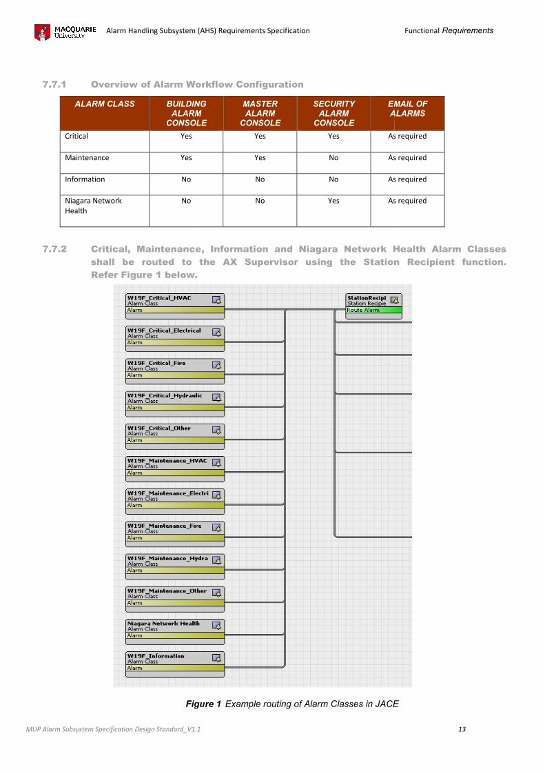
7.7.1 Overview of Alarm Workflow Configuration
ALARM CLASS BUILDING ALARM
CONSOLE
Critical Yes
Maintenance Yes
Information No
Niagara Network
Health
No
7.7.2 Critical, Maintenance, Information and Niagara Network Health Alarm Classes
shall be routed to the AX Supervisor using the Station
Refer Figure 1 below.
Figure 1
Alarm Handling Subsystem (AHS) Requirements Specification
Design Standard_V1.1
Overview of Alarm Workflow Configuration
BUILDING ALARM
CONSOLE
MASTER ALARM
CONSOLE
SECURITY ALARM
CONSOLE
EMAIL OF ALARMS
Yes Yes As required
Yes No As required
No No As required
No Yes As required
Critical, Maintenance, Information and Niagara Network Health Alarm Classes
shall be routed to the AX Supervisor using the Station
Refer Figure 1 below.
Figure 1 Example routing of Alarm Classes in JACE
Functional Requirements
13
EMAIL OF ALARMS
As required
As required
As required
As required
Critical, Maintenance, Information and Niagara Network Health Alarm Classes
shall be routed to the AX Supervisor using the Station Recipient function.
Example routing of Alarm Classes in JACE
Alarm Handling Subsystem (AHS) Requirements Specification
MUP Alarm Subsystem Specification Design Standard_V1.1
Each building is to have a Local Console graphic accessible via the building web graphic.
Critical Alarms shall be displayed on the Building Alarm Console, the Master Alarm Console and the Security
Alarm Console.
Maintenance Alarms shall be displayed on both the Building Console Display and the Master Console Display.
An Email Recipient can be defined and linked to any Alarm. By default alarms will not be sent via emails unless
requested.
Additional Alarms Consoles and Email recipients can be added as required by Macquarie University Property.
NOTE: Alarm notification relies solely on the campus WAN infrastructure being operational. Any outage will
result in the alarms not being delivered.
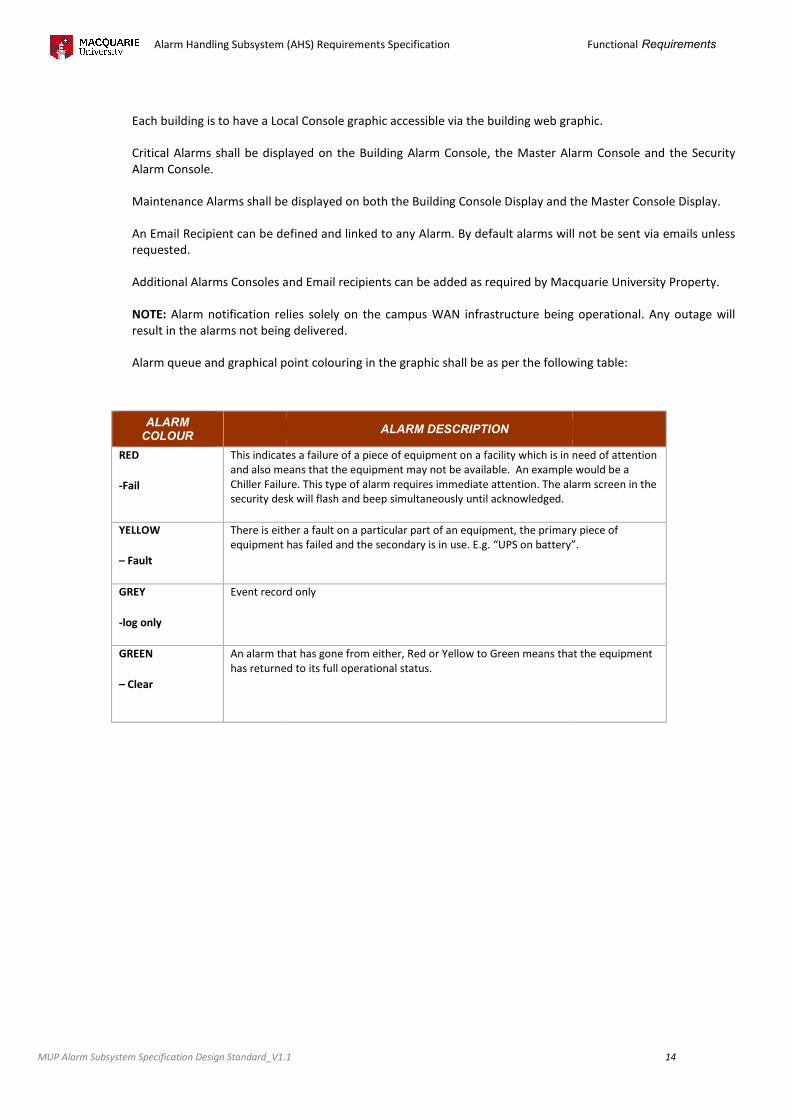
Alarm queue and graphical point colouring
ALARM COLOUR
RED
-Fail
This indicates a failure of a piece of equipment on a facility which is in need of attention
and also means that the
Chiller Failure. This type of alarm requires immediate attention. The alarm screen in the
security desk will flash and beep simultaneously until acknowledged.
YELLOW
– Fault
There is either a fault o
equipment has failed and the secondary is in use. E.g. “UPS on battery”.
GREY
-log only
Event record only
GREEN
– Clear
An alarm that has gone from either, Red or Yellow to Green means that the e
has returned to its full operational status.
Alarm Handling Subsystem (AHS) Requirements Specification
Design Standard_V1.1
Each building is to have a Local Console graphic accessible via the building web graphic.
Critical Alarms shall be displayed on the Building Alarm Console, the Master Alarm Console and the Security
aintenance Alarms shall be displayed on both the Building Console Display and the Master Console Display.
An Email Recipient can be defined and linked to any Alarm. By default alarms will not be sent via emails unless
and Email recipients can be added as required by Macquarie University Property.
Alarm notification relies solely on the campus WAN infrastructure being operational. Any outage will
result in the alarms not being delivered.
Alarm queue and graphical point colouring in the graphic shall be as per the following
ALARM DESCRIPTION
This indicates a failure of a piece of equipment on a facility which is in need of attention
and also means that the equipment may not be available. An example would be a
Chiller Failure. This type of alarm requires immediate attention. The alarm screen in the
security desk will flash and beep simultaneously until acknowledged.
There is either a fault on a particular part of an equipment, the primary piece of
equipment has failed and the secondary is in use. E.g. “UPS on battery”.
Event record only
An alarm that has gone from either, Red or Yellow to Green means that the e
has returned to its full operational status.
Functional Requirements
14
Each building is to have a Local Console graphic accessible via the building web graphic.
Critical Alarms shall be displayed on the Building Alarm Console, the Master Alarm Console and the Security
aintenance Alarms shall be displayed on both the Building Console Display and the Master Console Display.
An Email Recipient can be defined and linked to any Alarm. By default alarms will not be sent via emails unless
and Email recipients can be added as required by Macquarie University Property.
Alarm notification relies solely on the campus WAN infrastructure being operational. Any outage will
the following table:
This indicates a failure of a piece of equipment on a facility which is in need of attention
equipment may not be available. An example would be a
Chiller Failure. This type of alarm requires immediate attention. The alarm screen in the
n a particular part of an equipment, the primary piece of
equipment has failed and the secondary is in use. E.g. “UPS on battery”.
An alarm that has gone from either, Red or Yellow to Green means that the equipment
Alarm Handling Subsystem (AHS) Requirements Specification
MUP Building Management Systems (BMS) Design Standard_V1.1
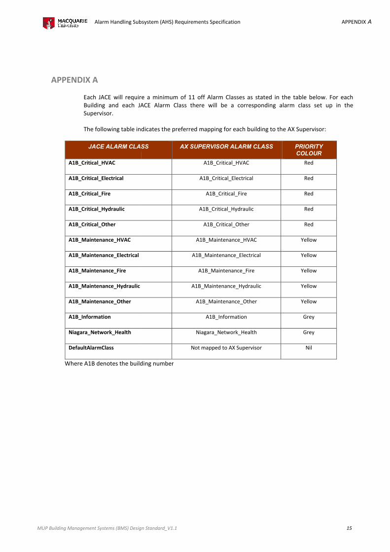
APPENDIX A
Each JACE will require a minimum of 11 off Alarm Classes as stated in the table below. For each
Building and each JACE Alarm Class there will be a corresponding alarm class set up in the
Supervisor.
The following table indicates the preferred mapping for each building to the AX Supervisor:
JACE ALARM CLASS
A1B_Critical_HVAC
A1B_Critical_Electrical
A1B_Critical_Fire
A1B_Critical_Hydraulic
A1B_Critical_Other
A1B_Maintenance_HVAC
A1B_Maintenance_Electrical
A1B_Maintenance_Fire
A1B_Maintenance_Hydraulic
A1B_Maintenance_Other
A1B_Information
Niagara_Network_Health
DefaultAlarmClass
Where A1B denotes the building number
Alarm Handling Subsystem (AHS) Requirements Specification
Design Standard_V1.1
Each JACE will require a minimum of 11 off Alarm Classes as stated in the table below. For each
Building and each JACE Alarm Class there will be a corresponding alarm class set up in the
ble indicates the preferred mapping for each building to the AX Supervisor:
JACE ALARM CLASS AX SUPERVISOR ALARM CLASS
A1B_Critical_HVAC
A1B_Critical_Electrical
A1B_Critical_Fire
A1B_Critical_Hydraulic
A1B_Critical_Other
A1B_Maintenance_HVAC
A1B_Maintenance_Electrical
A1B_Maintenance_Fire
A1B_Maintenance_Hydraulic
A1B_Maintenance_Other
A1B_Information
Niagara_Network_Health
Not mapped to AX Supervisor
Where A1B denotes the building number
APPENDIX A
15
Each JACE will require a minimum of 11 off Alarm Classes as stated in the table below. For each
Building and each JACE Alarm Class there will be a corresponding alarm class set up in the
ble indicates the preferred mapping for each building to the AX Supervisor:
PRIORITY
COLOUR
Red
Red
Red
Red
Red
Yellow
Yellow
Yellow
Yellow
Yellow
Grey
Grey
Nil
Alarm Handling Subsystem (AHS) Requirements Specification
MUP Building Management Systems (BMS) Design Standard_V1.1
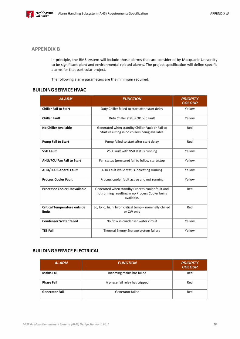
APPENDIX B
In principle, the BMS system will include those alarms that are considered by Macquarie University
to be significant plant and environmental related alarms. The project
alarms for that particular project.
The following alarm parameters are the minimum required:
BUILDING SERVICE HVAC
ALARM
Chiller Fail to Start
Chiller Fault
No Chiller Available
Pump Fail to Start
VSD Fault
AHU/FCU Fan Fail to Start
AHU/FCU General Fault
Process Cooler Fault
Processor Cooler Unavailable
Critical Temperature outside
limits
Condensor Water failed
TES Fail
BUILDING SERVICE ELECTRICAL
ALARM
Mains Fail
Phase Fail
Generator Fail
Alarm Handling Subsystem (AHS) Requirements Specification
Design Standard_V1.1
In principle, the BMS system will include those alarms that are considered by Macquarie University
to be significant plant and environmental related alarms. The project specification will define specific
alarms for that particular project.
The following alarm parameters are the minimum required:
FUNCTION
Duty Chiller failed to start after start delay
Duty Chiller status OK but Fault
Generated when standby Chiller Fault or Fail to
Start resulting in no chillers being available
Pump failed to start after start delay
VSD Fault with VSD status running
Fan status (pressure) fail to follow start/stop
AHU Fault while status indicating running
Process cooler fault active and not running
Generated when standby Process cooler fault and
not running resulting in no Process Cooler being
available.
Lo, lo lo, hi, hi hi on critical temp – nominally chilled
or CW only
No flow in condenser water circuit
Thermal Energy Storage system failure
ELECTRICAL
FUNCTION
Incoming mains has failed
A phase fail relay has tripped
Generator failed
APPENDIX B
16
In principle, the BMS system will include those alarms that are considered by Macquarie University
specification will define specific
PRIORITY
COLOUR
Yellow
Yellow
Red
Red
Yellow
Yellow
Yellow
Yellow
Red
Red
Yellow
Yellow
PRIORITY
COLOUR
Red
Red
Red
Alarm Handling Subsystem (AHS) Requirements Specification
MUP Building Management Systems (BMS) Design Standard_V1.1
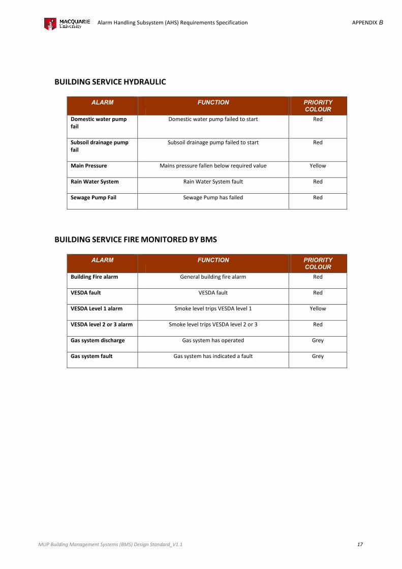
BUILDING SERVICE HYDRAULIC
ALARM
Domestic water pump
fail
Subsoil drainage pump
fail
Main Pressure
Rain Water System
Sewage Pump Fail
BUILDING SERVICE FIRE MONITORED
ALARM
Building Fire alarm
VESDA fault
VESDA Level 1 alarm
VESDA level 2 or 3 alarm
Gas system discharge
Gas system fault
Alarm Handling Subsystem (AHS) Requirements Specification
Design Standard_V1.1
HYDRAULIC
FUNCTION
Domestic water pump failed to start
Subsoil drainage pump failed to start
Mains pressure fallen below required value
Rain Water System fault
Sewage Pump has failed
MONITORED BY BMS
FUNCTION
General building fire alarm
VESDA fault
Smoke level trips VESDA level 1
Smoke level trips VESDA level 2 or 3
Gas system has operated
Gas system has indicated a fault
APPENDIX B
17
PRIORITY
COLOUR
Red
Red
Yellow
Red
Red
PRIORITY
COLOUR
Red
Red
Yellow
Red
Grey
Grey


![ZXG10 BSS (V6.20) Base Station Subsystem Alarm Handling Manual[1]](https://img.pdfslide.us/doc/110x75/5476ed5fb4af9f32248b45c9/zxg10-bss-v620-base-station-subsystem-alarm-handling-manual1.jpg)