Embed Size (px)
Citation preview

ALARA Activities at DOE2008 Report 4-1
Section FourALARA Activities at DOE 4A
LAR
A A
ctivities at DO
E
This section on ALARA activities is a vehicle to document successes and to point all DOE sites to those programs whose managers have confronted radiation protection issues and used innovative techniques to solve problems common to most DOE sites. DOE program and site offices and contractors who are interested in benchmarks of success and continuous improvement in the context of Integrated Safety Management and quality are encouraged to provide input to be included in future reports.
4.1. ALARA Activities at the Savannah River Site
4.1.1. Process Water Deionizer Disposition
A typical problem with any 50-plus-year-old facility is abandoned legacy equipment from past operations. At one time, K-Area Complex (KAC) was home to a heavy water moderated production reactor that used deionizers to clean the K Reactor process water. Each deionizer stands over 5 feet tall and weighs over 3000 pounds. Today, KAC is a packaging, handling, and storage facility for a variety of nuclear materials, including plutonium. With the current KAC mission, the radiologically contaminated deionizers were considered legacy equipment and not needed. A team was assembled to determine the safest and best way to remove them.
The plan for safe disposition included the following:
u Camera and RO-7 on extended cable sent over cells using the overhead crane to verify ID numbers and obtain dose rates (see Exhibit 4-1)
u Observed similar work being performed in R-area and P-area
u Lower dose deionizers dispositioned first
u Verified proper ventilation
u Preparation of work area
u Use of remote dose rate instruments and remote Kanne monitoring
u Remote performance of maintenance activities by experienced crane operator
u Dedicated team of workers
Nuclear Materials Storage Project/K-Area Complex has successfully dispositioned the first 8 of 16 process water deionizers that were no longer needed through the teamwork of Waste Management, Engineering, Radiological Protection, Rigging, Maintenance, and Operations personnel. The work was accomplished with minimal exposure and risk to the workers involved due to the use of long-handled tools, remote activities performed by a crane operator, and careful job preplanning. The lowest dose deionizers (< 5 mrem/hr) were dispositioned first. An experienced crane operator was able to perform maintenance activities such as venting and removal/installation of Hanford connectors while working from a clean area. This improvement reduced the time spent in the CA/ARA by 40 percent. Also, due to remote venting and remote Kanne monitoring of the line break, Personal Protective Equipment was minimized. A negative pressure respirator was worn for entry in lieu of a plastic suit that would have been needed if a mechanic had been required to manually perform the line break. The team worked together to minimize entries and assist those inside in maintaining distance during down periods. The deionizers were removed safely without a contamination event and ahead of schedule. The good ALARA techniques practiced during this evolution will be incorporated as the high-dose deionizers (maximum of 400 mrem/hr @ 30 cms and 900 mrem/hr at contact) are processed in 2009.

4-2 DOE Occupational Radiation Exposure
involving 260 W/O tasks planned and executed with 100% project management team PMT success and zero rework.
4.1.2. Radiological Hazard Controls for the MCU and 96H ARP Production Outage
The liquid waste operations interim salt disposition project (LWO ISDP) 241-96H Actinide Removal Process (ARP) and 241-278H Modular Caustic Side Solvent Extraction (MCU) facilities are designed to pretreat salt waste for an interim period prior to Salt Waste Processing Facility (SWPF) operation. The goal of pretreatment is to remove or reduce the radioactive material concentrations and the entrained sludge solids in the salt solutions. Strontium (Sr-90), actinides (Pu, U, Am), and solids are removed or reduced at ARP by using a monosodium titanate (MST) adsorption treatment followed by filtration. The cesium (Cs-137) is removed or reduced by using a caustic side solvent extraction process at MCU. Operation of these facilities began in April 2008 and will continue until the SWPF is operational.
LWO successfully completed the first major production outage (3 months) and restarted ISDP processing in January 2009. Outage accomplishments include implementing a document safety analysis DSA change to open up process cleaning options at MCU. A remotable DSS coalescer prefilter was designed, constructed, mocked-up, and installed into the tight confines of the MCU process area (see Exhibit 4-2). A feed and bleed modification was completed at MCU to reduce required operator intervention. Demisters were designed and installed on the 96H process vessel vent (PVV) jumpers to reduce dose accumulation in the PVV duct system. The outage scope involved thousands of safe construction, maintenance, and facility man-hours
There was a potential for high radiation exposure from high dose rates in the process cells at MCU and in the strike tank process cells and PVV lines at 96H ARP. The risk associated with coordination of a sequence of work activities that involved various work groups, including maintenance and construction (e.g., the decontaminated salt solution hold tank (DSSHT pump replacement by maintenance personnel was performed between prefilter installation steps by construction personnel due to the proximity of pumps to new filter location) (see Exhibits 4-3 and 4-4 for examples of tight work spaces). Exhibit 4-3: Coalescer media housing in MCU process cell.
Exhibit 4-4: MCU process cell entry for prefilter installation.
Exhibit 4-2: Coalescer media replacement mock-up.
Photo courtesy of Fermilab
Exhibit 4-3: Coalescer media housing in MCU process cell.
Photo courtesy of Fermilab
There was a potential for high radiation exposure from high dose rates in the process cells at MCU and in the strike tank process cells and PVV lines at 96H ARP. The risk associated with coordination of a sequence of work activities that involved various work groups, including maintenance and construction (e.g., the decontaminated salt solution hold tank (DSSHT pump replacement by maintenance personnel was performed between prefilter installation steps by construction personnel due to the proximity of pumps to new filter location) (see Exhibits 4-3 and 4-4 for examples of tight work spaces). Exhibit 4-3: Coalescer media housing in MCU process cell.
Exhibit 4-4: MCU process cell entry for prefilter installation.
Exhibit 4-1: Dose rate being taken with an RO-7 used as an extended tool to maximize distance from deionizer.
4.1.2 Radiological Hazard Controls for the MCU and 96H ARP Production Outage The liquid waste operations interim salt disposition project (LWO ISDP) 241-96H Actinide Removal Process (ARP) and 241-278H Modular Caustic Side Solvent Extraction (MCU) facilities are designed to pretreat salt waste for an interim period prior to Salt Waste Processing Facility (SWPF) operation. The goal of pretreatment is to remove or reduce the radioactive material concentrations and the entrained sludge solids in the salt solutions. Strontium (Sr-90), actinides (Pu, U, Am), and solids are removed or reduced at ARP by using a monosodium titanate (MST) adsorption treatment followed by filtration. The cesium (Cs-137) is removed or reduced by using a caustic side solvent extraction process at MCU. Operation of these facilities began in April 2008 and will continue until the SWPF is operational. LWO successfully completed the first major production outage (3 months) and restarted ISDP processing in January 2009. Outage accomplishments include implementing a document safety analysis DSA change to open up process cleaning options at MCU. A remotable DSS coalescer prefilter was designed, constructed, mocked-up, and installed into the tight confines of the MCU process area (see Exhibit 4-2). A feed and bleed modification was completed at MCU to reduce required operator intervention. Demisters were designed and installed on the 96H process vessel vent (PVV) jumpers to reduce dose accumulation in the PVV duct system. The outage scope involved thousands of safe construction, maintenance, and facility man-hours involving 260 W/O tasks planned and executed with 100% project management team PMT success and zero rework. Exhibit 4-2: Coalescer media replacement mock-up.
Exhibit 4-1: Dose rate being taken with an RO-7 used as an extended tool to maximize distance from deionizer.
Photo courtesy of Fermilab
There was a potential for high radiation exposure from high dose rates in the process cells at MCU and in the strike tank process cells and PVV lines at 96H ARP. The risk associated with coordination of a sequence of work activities that involved various work groups, including maintenance and construction (e.g., the decontaminated salt solution hold tank (DSSHT pump replacement by maintenance personnel was performed between prefilter installation steps by construction personnel due to the proximity of pumps to new filter location) (see Exhibits 4-3 and 4-4 for examples of tight work spaces).
There was a potential for spread of contamination from line breaks involving jumper replacement (96H ARP), cutting/welding process piping, coalescer replacement,

ALARA Activities at DOE2008 Report 4-3
installation of flush connections on PVV lines at 96H ARP, and pump replacement activities.
These hazards were minimized by performing extensive dose profiles through camera ports and cell covers. Profile data were used to determine the best combination of de-inventory and flushing activities and thereby reduce the dose rates to a manageable rate with supplemental lead shielding in key locations. The spread of contamination, as well as radiation exposure, were minimized by performing mock-ups, using containment around lines or work areas, and ensuring appropriate ventilation controls were used (no more than 3 cell covers removed at MCU when line breaks were performed.) In addition, work packages included worker dose limits per day based on real time monitoring of electronic pocket dosimeters EPD readings via the Teletrak dose tracking system.
The maximum dose rate prior to de-inventory in the work area was 3 R/hr to 4 R/hr but was reduced to a maximum rate of 1.7 R/hr prior to shielding. After preparation activities were completed, work area dose rates ranged from 40 mrem/hr to 140 mrem/hr for most of the outage scope work. The total dose for the MCU and 96H ARP outage activities were 9552 mrem and 386 mrem, respectively (estimated to be >25 rem), with a maximum individual worker dose of 278 mrem for the DSS prefilter installation activities (see Exhibit 4-5 for dose summary data).
Engineering Controls
The outage scope involved hazardous and complex work requiring the following:
u Elaborate de-inventory and flush plans/procedures
u Large quantities of creative “first of a kind” shielding designed/fabricated/installed along with work platforms
u Large containment areas (windbreaks) above process cells for various jobs within adjacent cell cover areas with HEPA ventilation as needed (see Exhibit 4-6)
u Teletrak dose tracking system for all major outage jobs involving the potential for significant dose
This work reduced dose fields from >2 R/hr to ~40 mrem/hr to 70 mrem/hr working rate and yielded >4.02 R personnel dose savings for the outage.
Exhibit 4-4: MCU process cell entry for prefilter installation.
Photo courtesy of Fermilab
There was a potential for spread of contamination from line breaks involving jumper replacement (96H ARP), cutting/welding process piping, coalescer replacement, installation of flush connections on PVV lines at 96H ARP, and pump replacement activities.
These hazards were minimized by performing extensive dose profiles through camera ports and cell covers. Profile data were used to determine the best combination of de-inventory and flushing activities and thereby reduce the dose rates to a manageable rate with supplemental lead shielding in key locations. The spread of contamination, as well as radiation exposure, were minimized by performing mock-ups, using containment around lines or work areas, and ensuring appropriate ventilation controls were used (no more than 3 cell covers removed at MCU when line breaks were performed.) In addition, work packages included worker dose limits per day based on real time monitoring of electronic pocket dosimeters EPD readings via the Teletrak dose tracking system. The maximum dose rate prior to de-inventory in the work area was 3 R/hr to 4 R/hr but was reduced to a maximum rate of 1.7 R/hr prior to shielding. After preparation activities were completed, work area dose rates ranged from 40 mrem/hr to 140 mrem/hr for most of the outage scope work. The total dose for the MCU and 96H ARP outage activities were 9552 mrem and 386 mrem, respectively (estimated to be >25 rem), with a maximum individual worker dose of 278 mrem for the DSS prefilter installation activities (see Exhibit 4-5 for dose summary data). Exhibit 4-5: MCU and ARP outage dose summary.
Exhibit 4-5: MCU and ARP outage dose summary.
Photo courtesy of Fermilab
ARP (mrem)
MCU (mrem)
3869,552
MCU/ARP TOTALS (1/20/09)
1701,91540-12060-200 / 1100
Max individual (mrem)
Total Dose (mrem)
Work Area with Lead(mR/hr)
Work area / MAX (mR/hr)
SIPHON BREAK at SSRT#1
104312DSS90-140SE 50
DSS90-300 SE 50-3602980
Max individual (mrem)
Total Dose (mrem)
Work Area with Lead(mR/hr)
DSS / SEWork area / MAX (mR/hr)
DSS/SE COALESCER CHANGE-OUT
2786,29450-11050-480 /1700
Max individual (mrem)
Total Dose (mrem)
Work Area with Lead(mR/hr)
Work area / MAX (mR/hr)
*DSS Pre-Filter
33308DSS40-110 SE No Lead
DSS50-300 SE 40-1301000
Max individual (mrem)
Total Dose (mrem)
Work Area with Lead(mR/hr)
DSS / SE Work area / MAX (mR/hr)
DSS and SE PUMP REPLACEMENT
50237N/A10-30 /200
Max individual (mrem)
Total Dose (mrem)
Work Area with Lead(mR/hr)
Work area / MAX (mR/hr)
CausticFeed/Bleed Contactor RoomLegend
Infrequent activity *
One time activity
* DSS Pre-filter installation was one time activity but filter assembly could be remotely changed on an infrequent basis.
Engineering Controls The outage scope involved hazardous and complex work requiring the following:
- Elaborate de-inventory and flush plans/procedures - Large quantities of creative "first of a kind" shielding designed/fabricated/installed along with work platforms - Large containment areas (windbreaks) above process cells for various jobs within adjacent cell cover areas
with HEPA ventilation as needed (see Exhibit 4-6) - Teletrak dose tracking system for all major outage jobs involving the potential for significant dose
This work reduced dose fields from >2 R/hr to ~40 mrem/hr to 70 mrem/hr working rate and yielded >4.02 R personnel dose savings for the outage. Exhibit 4-6: Windbreak installed around the evaporator cell area.
Exhibit 4-6: Windbreak installed around the evaporator cell area.
Photo courtesy of Fermilab
ARP (mrem)
MCU (mrem)
3869,552
MCU/ARP TOTALS (1/20/09)
1701,91540-12060-200 / 1100
Max individual (mrem)
Total Dose (mrem)
Work Area with Lead(mR/hr)
Work area / MAX (mR/hr)
SIPHON BREAK at SSRT#1
104312DSS90-140SE 50
DSS90-300 SE 50-3602980
Max individual (mrem)
Total Dose (mrem)
Work Area with Lead(mR/hr)
DSS / SEWork area / MAX (mR/hr)
DSS/SE COALESCER CHANGE-OUT
2786,29450-11050-480 /1700
Max individual (mrem)
Total Dose (mrem)
Work Area with Lead(mR/hr)
Work area / MAX (mR/hr)
*DSS Pre-Filter
33308DSS40-110 SE No Lead
DSS50-300 SE 40-1301000
Max individual (mrem)
Total Dose (mrem)
Work Area with Lead(mR/hr)
DSS / SE Work area / MAX (mR/hr)
DSS and SE PUMP REPLACEMENT
50237N/A10-30 /200
Max individual (mrem)
Total Dose (mrem)
Work Area with Lead(mR/hr)
Work area / MAX (mR/hr)
CausticFeed/Bleed Contactor RoomLegend
Infrequent activity *
One time activity
* DSS Pre-filter installation was one time activity but filter assembly could be remotely changed on an infrequent basis.
Engineering Controls The outage scope involved hazardous and complex work requiring the following:
- Elaborate de-inventory and flush plans/procedures - Large quantities of creative "first of a kind" shielding designed/fabricated/installed along with work platforms - Large containment areas (windbreaks) above process cells for various jobs within adjacent cell cover areas
with HEPA ventilation as needed (see Exhibit 4-6) - Teletrak dose tracking system for all major outage jobs involving the potential for significant dose
This work reduced dose fields from >2 R/hr to ~40 mrem/hr to 70 mrem/hr working rate and yielded >4.02 R personnel dose savings for the outage. Exhibit 4-6: Windbreak installed around the evaporator cell area.

4-4 DOE Occupational Radiation Exposure
4.1.3. Two F Evaporator Gravity Drain Line (GDL) Cleaning
F Tank Farm waste storage facility includes an evaporator. The evaporator reduces the volume of waste stored. During the waste processing, transfer and drain lines may become plugged. Recently, the Gravity Drain Line (GDL) became plugged and a work package was developed to remove the plug.
This is not the first time the GDL has become plugged and the pluggage removed with a high-pressure hose. During the development of the work package, a task in H Tank Farm was performed, which included a glove bag to collect back flush water during the flushing operation. The adapter used in H Tank Farm extended through the cell port and into the glove bag to collect the back flush.
Maintenance designed and fabricated an adapter/guide plate in F Tank Farm. This would eliminate the potential of the back flush water outside the primary containment (e.g., cell cover) and would seal the cell cover port opening during the high-pressure flush.
Hazards
Radiation Exposure
u Use of the adapter provided shielding with the use of the installed cell cover.
u If the adapter had not been used, a contingency plan was developed to use a bridge
(installed in the location of the removed cell cover).
Spread of Contamination
u Blue fog applied to the cell area (fixative coating)
u Cell ventilation in operation
Comments
Dose Rates
u 400 mrem/hr extremity (Lancing hose)
u 300 mrem/hr skin (Lancing hose)
u 1 mrem/hr whole body (Lancing hose)
Actual Dose
u 13 mrem (estimated dose160 mrem)
Engineering Controls
u Windbreak
u Cell ventilation
u Wind speed limit
u Adapter/guide cover
u Blue fog cell area
u Flushing and sleeving the lancing hose during removal
The adapter/guide cover plate included the following features (See Exhibit 4-7):
u Flush rig to flush the lancing hose during removal
u Guide tube to align the lancing hose with the catheter port
u Seal and secure to the cell cover port opening
u Used as a sleever device (deploy sleeve, as the hose was being removed)
Exhibit 4-7: Adapter/guide cover plate.
Photo courtesy of Fermilab
The adapter/guide cover plate included the following features (See Exhibit 4-7): - Flush rig to flush the lancing hose during removal - Guide tube to align the lancing hose with the catheter port - Seal and secure to the cell cover port opening - Used as a sleever device (deploy sleeve, as the hose was being removed) Exhibit 4-7: Adapter/guide cover plate.
4.1.4 Flushing of the 16.1-1s Decanter The 16.1-1S decanter is used in the RERUN process of H-Canyon to separate organic and aqueous solutions prior to being processed through evaporators. On January 20, 2008, it was noted that all solution going through the decanter was being pushed out the organic side of the decanter, indicating pluggage in the underflow weir. Engineering and Operations jointly devised a plan to obtain video footage of the inside of the decanter. The video footage confirmed their assumptions that the decanter, after 50 years of service, had become plugged with sand from sump material being transferred through the decanter.
The attempts to pump the sand out of the decanter were unsuccessful, and a plan was developed to remove the decanter remotely, using the New Hot Crane, to the H-Canyon Railroad Tunnel where internal flushes would be made using manual tools. This challenging job had never been performed and there were many unknown variables. (See Exhibit 4-8).
4.1.4. Flushing of the 16.1-1s Decanter
The 16.1-1S decanter is used in the RERUN process of H-Canyon to separate organic and aqueous solutions prior to being processed through evaporators. On January 20, 2008, it was noted that all solution going through the decanter was being pushed out the organic side of the decanter, indicating pluggage in the underflow weir.

ALARA Activities at DOE2008 Report 4-5
Engineering and Operations jointly devised a plan to obtain video footage of the inside of the decanter. The video footage confirmed their assumptions that the decanter, after 50 years of service, had become plugged with sand from sump material being transferred through the decanter.
The attempts to pump the sand out of the decanter were unsuccessful, and a plan was developed to remove the decanter remotely, using the New Hot Crane, to the H-Canyon Railroad Tunnel where internal flushes would be made using manual tools. This challenging job had never been performed and there were many unknown variables. (See Exhibit 4-8).
Exhibit 4-8: Decanter
Photo courtesy of Fermilab Exhibit 4-8: Decanter Hazards
The decanter had to be deconned to acceptable contamination/radiation rates.
The initial radiological surveys of the work were completed using the Teletrack instrumentation. The readings in Exhibit 4-9 represent a combination of doses at 5 cm and 30 cm distances from the decanter.
Exhibit 4-9. Combination of doses at 5cm and 30cm distances from the decanter.
Radiation Exposure Control
Photo courtesy of Fermilab
Exhibit 4-8: Decanter Hazards
The decanter had to be deconned to acceptable contamination/radiation rates.
The initial radiological surveys of the work were completed using the Teletrack instrumentation. The readings in Exhibit 4-9 represent a combination of doses at 5 cm and 30 cm distances from the decanter.
Exhibit 4-9. Combination of doses at 5cm and 30cm distances from the decanter.
Radiation Exposure Control
Radiation Exposure Control
u Use of an extended water lance during the flushing
u Performed initial survey of the vessel using remote equipment
u Use of the tungsten gloves for extremity exposure control
Contamination Control
u Use of a collection tray with a material mesh to capture the waste
u Use the building ventilation and the floor contour in the railroad tunnel as engineering controls
u In addition to the plastic suit, the worker donned a pair of galoshes and an apron
u The decanter was positioned to the southern end of the tunnel to use building design during the drainage of flush water
Comments
Dose Rates
At 5 cm: 8544 mrem/hr skin (decanter nozzles) 450 mrem/hr whole body (cecanter nozzles) At 30 cm: 3009 mrem/hr skin (decanter nozzles) 195 mrem/hr whole body (cecanter nozzles)
Hazards
The decanter had to be deconned to acceptable contamination/radiation rates.
The initial radiological surveys of the work were completed using the Teletrack instrumentation. The readings in Exhibit 4-9 represent a combination of doses at 5 cm and 30 cm distances from the decanter.
Exhibit 4-9: Combination of doses at 5cm and 30cm distances from the decanter.
4-6 DOE Occupational Radiation Exposure
Actual Cumulative Dose
u 1110 mrem/hr extremity
u 420 mrem/hr shallow
u 15 mrem/hr whole body
Recorded dose on the radiological work permit for task: total 112 mrem.
After several weeks of planning and preparation, the decanter was successfully moved to the H-Canyon Railroad Tunnel and flushed. After flushing was completed, the decanter was remotely reinstalled, checked for leaks, and declared back in service. This potentially saved the company more than $1 million.
This is another example of the expertise and willingness of the H-Canyon Team. Hats off to all that were involved in the planning and performance of this once-in-a-lifetime feat!
4.1.5. Liquid Level Jumper - Unclogged
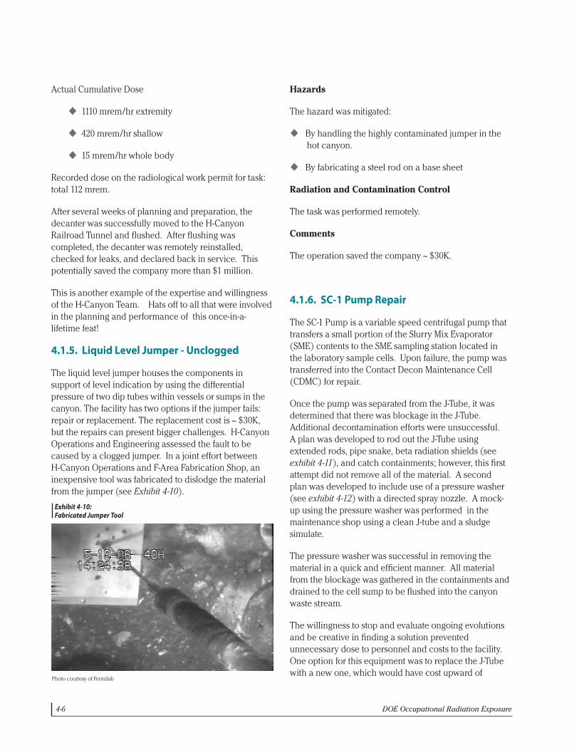
The liquid level jumper houses the components in support of level indication by using the differential pressure of two dip tubes within vessels or sumps in the canyon. The facility has two options if the jumper fails: repair or replacement. The replacement cost is ~ $30K, but the repairs can present bigger challenges. H-Canyon Operations and Engineering assessed the fault to be caused by a clogged jumper. In a joint effort between H-Canyon Operations and F-Area Fabrication Shop, an inexpensive tool was fabricated to dislodge the material from the jumper (see Exhibit 4-10).
Hazards
The hazard was mitigated:
u By handling the highly contaminated jumper in the hot canyon.
u By fabricating a steel rod on a base sheet
Radiation and Contamination Control
The task was performed remotely.
Comments
The operation saved the company ~ $30K.
4.1.6. SC-1 Pump Repair
The SC-1 Pump is a variable speed centrifugal pump that transfers a small portion of the Slurry Mix Evaporator (SME) contents to the SME sampling station located in the laboratory sample cells. Upon failure, the pump was transferred into the Contact Decon Maintenance Cell (CDMC) for repair.
Once the pump was separated from the J-Tube, it was determined that there was blockage in the J-Tube. Additional decontamination efforts were unsuccessful. A plan was developed to rod out the J-Tube using extended rods, pipe snake, beta radiation shields (see exhibit 4-11), and catch containments; however, this first attempt did not remove all of the material. A second plan was developed to include use of a pressure washer (see exhibit 4-12) with a directed spray nozzle. A mock-up using the pressure washer was performed in the maintenance shop using a clean J-tube and a sludge simulate.
The pressure washer was successful in removing the material in a quick and efficient manner. All material from the blockage was gathered in the containments and drained to the cell sump to be flushed into the canyon waste stream.
The willingness to stop and evaluate ongoing evolutions and be creative in finding a solution prevented unnecessary dose to personnel and costs to the facility. One option for this equipment was to replace the J-Tube with a new one, which would have cost upward of
Exhibit 4-10: Fabricated Jumper Tool
Photo courtesy of Fermilab
Exhibit 4-10: Fabricated Jumper Tool
Hazards The hazard was mitigated:
- By handling the highly contaminated jumper in the hot canyon. - By fabricating a steel rod on a base sheet
Radiation and Contamination Control The task was performed remotely. Comments The operation saved the company ~ $30K. 4.1.6 SC-1 Pump Repair The SC-1 Pump is a variable speed centrifugal pump that transfers a small portion of the Slurry Mix Evaporator (SME) contents to the SME sampling station located in the laboratory sample cells. Upon failure, the pump was transferred into the Contact Decon Maintenance Cell (CDMC) for repair. Once the pump was separated from the J-Tube, it was determined that there was blockage in the J-Tube. Additional decontamination efforts were unsuccessful. A plan was developed to rod out the J-Tube using extended rods, pipe snake, beta radiation shields (see exhibit 4-11), and catch containments; however, this first attempt did not remove all of the material. A second plan was developed to include use of a pressure washer (see exhibit 4-12) with a directed spray nozzle. A mock-up using the pressure washer was performed in the maintenance shop using a clean J-tube and a sludge simulate.

ALARA Activities at DOE2008 Report 4-7
$200,000. The use of the pressure washer in the CDMC will be applied to other pumps in the future.
Radiation Exposure Control
u Use of rubber mats and lexan to shield the beta radiation and reduce the extremity dose
u Use of the Teletrak Teledosimetry System along with Electronic Personnel Dosimeters (EPDs) and timekeeper to provide real time monitoring of personnel dose
u Workers were restricted from cell work until dosimetry results were received.
u Maintenance mechanics were rotated to spread the collective dose
u Reach-it tool was used for handling ceramic reducer (see Exhibit 4-13).
Contamination Control
u Cell ventilation in operation
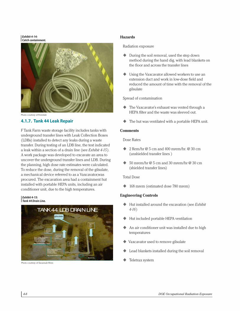
u Use of catch containments to prevent spread of contamination (see Exhibit 4-14).
u CDMC floor was prepared with plastic
u Plastic suits were worn to protect the workers from contaminated liquid
Comments
Maximum Dose Rates
40 rem/hr extremity 12 rem/hr skin 300 mrem/hr whole body
Actual Dose - 1.179 rem
Exhibit 4-11: Extended rod with betashield.
Exhibit 4-12: Pressure washer wand.
Photo courtesy of Fermilab
Photo courtesy of Fermilab
The pressure washer was successful in removing the material in a quick and efficient manner. All material from the blockage was gathered in the containments and drained to the cell sump to be flushed into the canyon waste stream. The willingness to stop and evaluate ongoing evolutions and be creative in finding a solution prevented unnecessary dose to personnel and costs to the facility. One option for this equipment was to replace the J-Tube with a new one, which would have cost upward of $200,000. The use of the pressure washer in the CDMC will be applied to other pumps in the future. Radiation Exposure Control - Use of rubber mats and lexan to shield the beta radiation and reduce the extremity dose - Use of the Teletrak Teledosimetry System along with Electronic Personnel Dosimeters (EPDs) and
timekeeper to provide real time monitoring of personnel dose - Workers were restricted from cell work until dosimetry results were received. - Maintenance mechanics were rotated to spread the collective dose - Reach-it tool was used for handling ceramic reducer (see Exhibit 4-13). Contamination Control - Cell ventilation in operation - Use of catch containments to prevent spread of contamination (see Exhibit 4-14). - CDMC floor was prepared with plastic - Plastic suits were worn to protect the workers from contaminated liquid Comments Maximum Dose Rates 40 rem/hr extremity 12 rem/hr skin 300 mrem/hr whole body Actual Dose - 1.179 rem
Exhibit 4-11: Extended rod with betashield.
Exhibit 4-12: Pressure washer wand.
Exhibit 4-13: Reach-It Tool.
Exhibit 4-13: Reach-It Tool.
Photo courtesy of Fermilab
Exhibit 4-12: Pressure washer wand.
Exhibit 4-13: Reach-It Tool.
4-8 DOE Occupational Radiation Exposure
4.1.7. Tank 44 Leak Repair
F Tank Farm waste storage facility includes tanks with underground transfer lines with Leak Collection Boxes (LDBs) installed to detect any leaks during a waste transfer. During testing of an LDB line, the test indicated a leak within a section of a drain line (see Exhibit 4-15). A work package was developed to excavate an area to uncover the underground transfer lines and LDB. During the planning, high dose rate estimates were calculated. To reduce the dose, during the removal of the gilsulate, a mechanical device referred to as a Vaxcavator,was procured. The excavation area had a containment hut installed with portable HEPA units, including an air conditioner unit, due to the high temperatures.
Exhibit 4-14: Catch containment.
4.1.7 Tank 44 Leak Repair F Tank Farm waste storage facility includes tanks with underground transfer lines with Leak Collection Boxes (LDBs) installed to detect any leaks during a waste transfer. During testing of an LDB line, the test indicated a leak within a section of a drain line (see Exhibit 4-15). A work package was developed to excavate an area to uncover the underground transfer lines and LDB. During the planning, high dose rate estimates were calculated. To reduce the dose, during the removal of the gilsulate, a mechanical device referred to as a Vaxcavator,was procured. The excavation area had a containment hut installed with portable HEPA units, including an air conditioner unit, due to the high temperatures. Exhibit 4-15: Tank 44 Drain Line
Tank 46 RecycleLine
Tank 45 RecycleLine
Tank 44RecycleLine
Tank 44LDB Drain Line
Dose Rates (mrem/hr.)WO/Lead Blankets2,000 Extremity
400 Whole Body
ND Contamination Levels
Dose Rates (mrem/hr.)W/Lead Blankets50 Extremity30 Whole Body
ND Contamination Levels
TANK 44 LDB DRAIN LINE
Repair Site
gilsulate
Hazards Radiation exposure
Exhibit 4-15: Tank 44 Drain Line.
Photo courtesy of Savannah River.
Exhibit 4-14: Catch containment.
Photo courtesy of Fermilab
Exhibit 4-14: Catch containment.
4.1.7 Tank 44 Leak Repair F Tank Farm waste storage facility includes tanks with underground transfer lines with Leak Collection Boxes (LDBs) installed to detect any leaks during a waste transfer. During testing of an LDB line, the test indicated a leak within a section of a drain line (see Exhibit 4-15). A work package was developed to excavate an area to uncover the underground transfer lines and LDB. During the planning, high dose rate estimates were calculated. To reduce the dose, during the removal of the gilsulate, a mechanical device referred to as a Vaxcavator,was procured. The excavation area had a containment hut installed with portable HEPA units, including an air conditioner unit, due to the high temperatures. Exhibit 4-15: Tank 44 Drain Line
Tank 46 RecycleLine
Tank 45 RecycleLine
Tank 44RecycleLine
Tank 44LDB Drain Line
Dose Rates (mrem/hr.)WO/Lead Blankets2,000 Extremity
400 Whole Body
ND Contamination Levels
Dose Rates (mrem/hr.)W/Lead Blankets50 Extremity30 Whole Body
ND Contamination Levels
TANK 44 LDB DRAIN LINE
Repair Site
gilsulate
Hazards Radiation exposure
Hazards
Radiation exposure
u During the soil removal, used the step down method during the hand dig, with lead blankets on the floor and across the transfer lines
u Using the Vaxcavator allowed workers to use an extension duct and work in low-dose field and reduced the amount of time with the removal of the gilsulate
Spread of contamination
u The Vaxcavator’s exhaust was vented through a HEPA filter and the waste was sleeved out.
u The hut was ventilated with a portable HEPA unit.
Comments
Dose Rates
u 2 Rem/hr @ 5 cm and 400 mrem/hr. @ 30 cm (unshielded transfer lines )
u 50 mrem/hr @ 5 cm and 30 mrem/hr @ 30 cm (shielded transfer lines)
Total Dose
u 168 mrem (estimated dose 780 mrem)
Engineering Controls
u Hut installed around the excavation (see Exhibit 4-16)
u Hut included portable HEPA ventilation
u An air conditioner unit was installed due to high temperatures
u Vaxcavator used to remove gilsulate
u Lead blankets installed during the soil removal
u Teletrax system

ALARA Activities at DOE2008 Report 4-9
- During the soil removal, used the step down method during the hand dig, with lead blankets on the floor and across the transfer lines
- Using the Vaxcavator allowed workers to use an extension duct and work in low-dose field and reduced the amount of time with the removal of the gilsulate
Spread of contamination - The Vaxcavator’s exhaust was vented through a HEPA filter and the waste was sleeved out. - The hut was ventilated with a portable HEPA unit.
Comments Dose Rates - 2 Rem/hr @ 5 cm and 400 mrem/hr. @ 30 cm (unshielded transfer lines ) - 50 mrem/hr @ 5 cm and 30 mrem/hr @ 30 cm (shielded transfer lines)
Total Dose - 168 mrem (estimated dose 780 mrem) Engineering Controls - Hut installed around the excavation (see Exhibit 4-16) - Hut included portable HEPA ventilation - An air conditioner unit was installed due to high temperatures - Vaxcavator used to remove gilsulate - Lead blankets installed during the soil removal - Teletrax system Exhibit 4-16: Hut Surrounding Excavation
- Mockups were performed to develop a method of sleeving out the spent gilsulate for Industrial Hygiene
controls - A HEPA filter was installed on the exhaust system - attached to the Vaxcavator (see Exhibit 4-17)
Exhibit 4-16: Hut Surrounding Excavation.
Exhibit 4-17: HEPA Filter Attached to Vaxcavator
- Gilsulate was removed through a 6” PVC pipe (prevented the suction duct from collapsing during the operation of Vaxcavator
- The 6” pipe also allowed a method to perform a radiation absorbed dose (RAD) profile to identify the depth of the transfer line Exhibit 4-17: HEPA Filter Attached to Vaxcavator
4.2. ALARA Activities at the Argonne National Laboratory
4.2.1. Improving Operational Tests of Radiation Protection Instruments
An instrument operational test fixture for neutron detectors has been designed and fabricated at Argonne National Laboratory for performing preoperational tests on portable neutron survey instruments (see Exhibit 4-18). This test fixture was developed after success with a test fixture for gamma-ray detectors.
For a number of years, Argonne has deployed a gamma operational test fixture containing a shielded 137Cs source. The source can be rotated into position to provide a gamma field for performing operational tests of higher range portable radiation protection instruments such as those containing ion chambers that need a source stronger than the typical check sources. The shielding is sufficient with the source in its “stored” position to allow the gamma test fixture to be located in the Health Physics Offices in buildings where radiological work is performed. Recently, this concept was extended to operational tests for neutron detecting instruments such as polyethylene-moderated 3He proportional counters (Rem Balls).
The neutron test fixture consists of a 12-inch cube of high-density polyethylene with 7.5% lithium/polyethylene as shielding material. Inside the cube is a 6.75-inch diameter drum containing a 200 mCi 241AmBe neutron source. The drum is rotated to move the source from the “stored” position, centered in the cube, to the “exposed” position, with the source directly under the top of the cabinet, for testing the survey instruments (see Exhibit 4-19). The position of the source is controlled by an operating handle projecting through a metal cabinet that totally encloses the neutron test fixture. An indexing mechanism ensures correct source position and a keyed lock secures the source in the “stored” position and prevents operation by unauthorized persons (see Exhibit 4-20, cabinet cover removed).
The test fixture makes it possible to check the performance of the neutron detector (Rem Ball) in a reproducible manner. There is a dimple in the top plate of the test fixture that indicates where to place the Rem Ball. The Rem Ball dose rate with the source exposed is 27 mrem per hour. With the source in the
Photo courtesy of Savannah River.
Photo courtesy of Savannah River.
u Mockups were performed to develop a method of sleeving out the spent gilsulate for Industrial Hygiene controls
u A HEPA filter was installed on the exhaust system - attached to the Vaxcavator (see Exhibit 4-17)
u Gilsulate was removed through a 6” PVC pipe (prevented the suction duct from collapsing during the operation of Vaxcavator
u The 6” pipe also allowed a method to perform a radiation absorbed dose (RAD) profile to identify the depth of the transfer line

4-10 DOE Occupational Radiation Exposure
Exhibit 4-18: Neutron Rig
Exhibit 4-18: Neutron Rig
Exhibit 4-19: Neutron Rig - Drum
Exhibit 4-19: Neutron Rig - Drum
Exhibit 4-20: Neutron Rig Index Plate - Locked
Exhibit 4-20: Neutron Rig Index Plate - Locked
Photo courtesy of Savannah River.
Photo courtesy of Savannah River.
Photo courtesy of Savannah River.
“stored” position, the dose rate is 0.6 mrem per hour at 30 cm from the cabinet. Until the neutron test fixture became available, operational checks were made by taking the Rem Ball to a location where there was a source of neutrons and checking to see if the Rem Ball detected neutrons. This can be inconvenient and nonreproducible. For example, in the past, the Rem Ball used to check incoming shipments in Building 46, Shipping and Receiving, was taken to another building where there was a drum containing a shielded neutron source. To make the operational check, the health physics technician brought the Rem Ball into contact with the drum containing the source. No attempt was made to place it in the same strength neutron field each time. Thus, the efficiency could have changed since calibration by more than 20% is the limit for remaining in service without detection of the change.