Embed Size (px)
Citation preview

AL11-i(i) (210-VI-NEH, Amend. AL6, October 2008)
ALABAMA SUPPLEMENTS TO THE
NATIONAL ENGINEERING FIELD HANDBOOK
CHAPTER 11. PONDS AND RESERVOIRS
Table of Contents
PAGE PART I - GENERAL 3. TYPES OF PONDS AND RESERVOIRS .................................................................................. AL11-6(1) PART II - EMBANKMENT PONDS 1. GEOLOGIC INVESTIGATIONS RECORDS OF SOILS INVESTIGATIONS ....................................................................... AL11-13(1) 4. PRINCIPAL SPILLWAYS DROP INLET SPILLWAYS Design ................................................................................................................................ AL11-16(1) 5. EMERGENCY SPILLWAYS .................................................................................................... AL11-17(1) 7. DESIGN OF EARTHFILL EMBANKMENTS ............................................................................ AL11-24(1) FOUNDATION CUTOFFS ................................................................................................. AL11-24(3) WORKSHEET FOR PONDS ...................................................................................... AL11-24(4) PART III - EXCAVATED PONDS 5. PLANNING AN EXCAVATED POND SELECTING POND DIMENSIONS ................................................................................... AL11-44(1) ESTIMATING THE VOLUME OF AN EXCAVATED POND ............................................. AL11-44(1)
EXHIBITS Exhibit AL11-1. Corrugated metal of smooth steel trash rack and deep water release ................ AL11-60(1) sleeve for ponds. Exhibit AL11-2. Trash rack and deep water release sleeve for plastic pipe pond risers. ............. AL11-60(2) Exhibit AL11-3. Location of trash rack - deep water release. ....................................................... AL11-60(3) Exhibit AL11-4. Table “B”. ............................................................................................................ AL11-60(4)
FIGURES Figure AL11-1. Circular Riser Inflow Curves ................................................................................ AL11-60(5) Figure AL11-2. Chart for Determining Inlet Proportions and Required Head Over Inlet .............. AL11-60(6) Figure AL11-3. Siphon Pipe Flow Rates ...................................................................................... AL11-60(7) Figure AL11-4. Design and construction layout survey notes for earth fill pond. .......................... AL11-60(8) Figure AL11-5. Construction check survey notes for earth fill pond. ............................................. AL11-60(12) Figure AL11-6. Design - construction layout survey notes for excavated pond. .......................... AL11-60(15)
TABLES Table AL11-1. Minimum hydrologic criteria and spillway capacity ............................................. AL11-6(1) Table AL11-2. Discharge in cubic feet per second (CFS) for pipe conduits with different head. AL 11-60(18) Table AL11-3. Weight and buoyant forces for corrugated metal, steel, and plastic pipe. ......... AL 11-60(19) Table AL11-4. Minimum riser base size to prevent flotation ...................................................... AL 11-60(20) Table AL11-5. End area tables for earthfill dams cubic yards per foot for embankment. .......... AL 11-60(21) Table AL11-6. Water needs for cattle. ....................................................................................... AL 11-60(29) Table AL11-7. Seepage and evaporation losses. ...................................................................... AL 11-60(30) Table AL11-8. Yardage tables - excavated ponds. .................................................................... AL 11-60(31) Table AL11-9. Excavated Pond, Alternative Design Table ........................................................ AL 11-60(37)

NATIONAL ENGINEERING FIELD HANDBOOK
AL11-6(1) (210-VI-NEH, Amend. AL6, October 2008)
PART I - GENERAL
3. TYPES OF PONDS AND RESERVOIRS
Classify embankment ponds according to the National Engineering Manual, Alabama Engineering Job Approval Authority, AL-ENG-1. Secure design criteria from NRCS Conservation Practice Standard Code 378, Pond and the following table:
Job Class1/
Principal Spillway (Storm 24 hour)
or Detention Storage
Design Storm (24 hour)
Emergency Spillway
Top of Dam or Freeboard
Elevation
years years2/ years
3/ feet
I 0.54/ 10 50 1
I 14/ 25 50 1
II 2 25 50 1
III5/ 5 50 50 1
IV6/ 10 50 50 1
V 10 50 50 6/
See NRCS Conservation Practice Standard, Code 378 - Pond for Footnotes. TABLE AL11-1. MINIMUM HYDROLOGIC CRITERIA AND SPILLWAY CAPACITY


NATIONAL ENGINEERING FIELD HANDBOOK
AL11-13(1)
PART II - EMBANKMENT PONDS
1. GEOLOGIC INVESTIGATIONS
RECORDS OF SOILS INVESTIGATIONS
A permanent record of all soil boring and test pits made will be maintained in the field office. Form SCS-ENG-538, AL-ENG-17 will be used to record soil borings on earth fill ponds and excavated ponds. Questionable sites and those requiring an engineer's approval will be recorded on SCS-ENG-538.


NATIONAL ENGINEERING FIELD HANDBOOK
AL11-16(1) (210-VI-NEH, Amend. AL6, October 2008)
4. PRINCIPAL SPILLWAYS
DROP INLET SPILLWAYS Design The design capacity of a principal spillway will be adequate to discharge long duration, continuous, or frequent design flows without flow through the emergency spillway. Table AL11-2, Figure AL11-1, AL11-2, and AL11-3, or an approved computer design program will be used to size the principal spillway and set the crest of the emergency spillway. For siphon pipes, assume full pipe flow when the reservoir surface elevation is D/3 above the high point of a siphon invert. Outlet slopes must be maintained at design grades until a suitable outlet is reached. Table AL11-3 and AL11-4 or an approved computer program should be used to determine the buoyant forces on riser pipes. Exhibit AL11-1, AL11-2, and AL11-3 show typical examples of trash racks and deep water releases. Form AL-ENG-4A may be used (with slight modifications) to design ponds with siphon principal spillways.


NATIONAL ENGINEERING FIELD HANDBOOK
AL11-17(1) (210-VI-NEH, Amend. AL6, October 2008)
5. EMERGENCY SPILLWAYS Emergency spillways can be designed utilizing Exhibit 11-2, 11-5, or an approved computer design program.


NATIONAL ENGINEERING FIELD HANDBOOK
AL11-24(1) (210-VI-NEH, Amend. AL6, October 2008)
7. DESIGN OF EARTHFILL EMBANKMENTS
The following definition and example shows how to use the tables and exhibits in the design and recording of data on Form AL-ENG-4A, POND DESIGN DATA, Figure AL11-4. Form AL-ENG-4A, or the WinPond, current version, shall be used on all engineering Class I and higher ponds which meet the Technical Guide Standard, Code 378 - Pond criteria. Job Class - determined from the criteria listed on Form AL-ENG-1, ENGINEERING JOB APPROVAL
CLASSIFICATION CHART in the National Engineering Manual. The actual JOB CLASS is determined by the largest controlling factor. Most of these can be determined from office data, with the effective height of dam determined from field surveys.
Soils - obtained from the soils map of the pond area and refers to the soils in the watershed. When several
soils and land uses exist, use Form AL-ENG-15, Worksheet for Detention Discharge for Ponds. Hydro.Gr. - Hydrologic Group - obtained from Chapter 2 or Technical Release 55. Land Use - refers to the type of land use in the drainage area (Row Crop, Pasture, Woods, etc.). Trtmt. - refers to the treatment or practice and cover type on the land use. Condition - Hydraulic condition of the cover in the watershed (poor, fair, good). Rainfall Dist. Type II or III - Circle the type rainfall distribution used for design. DA - Drainage Area (acres) - determined by scale or planimeter from stereoscopic or soil maps. Critical
drainage areas should be drawn from the contours on U.S.G.S. topographic maps and planimetered.
CN - Curve Number - a numerical value assigned a given soil-cover complex. (See Chapter 2). W/S Slope - Average Watershed Slope - the average watershed slope (percent) over the entire watershed can
be approximated by measuring the slope at several random locations throughout the watershed and averaging the results. The average watershed slope should be in line with slopes identified in the soil survey.
Flow Length – Length in feet along the flow path from the hydraulically most distant point to the pond dam. Tc – Time of concentration for the watershed. Rainfall (ps) or Rainfall (ES) - _______ in. ________ yr. - the rainfall amount and duration of event used in the
dam design for the principal spillway or emergency spillway. (See Table 7 in NRCS Conservation Practice Standard, Code 378, Pond, for the storm event for the class of pond.)
Ia – Initial abstraction (See Chapter 2). Ia/P(ps) – Ratio of Initial abstraction to design principal spillway storm. Qpeak(ps) – Unit peak discharge for the principal spillway storm.


NATIONAL ENGINEERING FIELD HANDBOOK
AL11-24(2) (210-VI-NEH, Amend. AL6, October 2008)
Vr - the volume of runoff in inches from the principal spillway storm that must be stored between the riser crest and emergency spillway crest and/or passed through the principal spillway pipe. Obtain the inches of runoff for the rainfall amount and CN. (See Chapter 2).
Qi (ps) - the peak inflow to the pond from the principal spillway storm. Vs - the volume of floodwater storage available in the pond between the permanent pool elevation and the
emergency spillway crest elevation in Ac-Ft. Obtain by averaging the area at the principal spillway crest and the emergency spillway crest, then multiplying by the elevation differences between the two areas. Surveys for determining pool areas will be documented in the survey notes or case file.
Vs(in.) - the volume of storage in acre-feet converted to inches. To convert, multiply _______ acre-feet x 12,
then divide by the drainage area _____ acres, which give _______ inches. Tab A or B - Circle whether using Table A or B as defined in Figure 1, Exhibit 11-4. Qo (ps) - The peak discharge for the principal spillway pipe (Table A or B, Exhibit 11-4). (A) Value from Table x Qi (ps) cfs = _________ cfs (Exhibit 11-4) (B) Value from Table x DA acres = ________ cfs (Exhibit AL11-4) H - Head in feet from emergency spillway crest to center of outlet end of barrel pipe or tailwater elevation. Pipe Size - records the riser and barrel diameters as determined from Table AL11-2 using Qo (ps) and (H) head
in feet. Ia/P(es) – Ratio of initial abstraction to design emergency spillway storm. Qpeak(es) – Unit peak discharge for the emergency spillway storm. R.O. (es) – Runoff in inches for the emergency spillway storm. Qes - The peak flow for the emergency spillway storm. Qes (design) - The design flow for the emergency spillway. Erosion Resistant Soil Yes or No, Circle One - Erosion Resistant Soils normally are considered to be hydrologic
soil groups C & D and heavy B soils. Easily eroded soils are A and weak B soils. Cover - Record the vegetation that will be established in the bottom of the emergency spillway. Conditon Stand - From knowledge of landuser and visual observation of conditions around the farm determine
conditions of vegetation to be fair or good. Height - Determine an expected average height of vegetation. Record the heights for stability and capacity. Slope - The average slope that can be secured in the emergency spillway exit channel. Vel. - Determine from Exhibit 11-2, Table 1, the maximum permissible velocity in fps for the vegetated spillway
using erosion resistant soil or easily eroded soil, cover vegetation and slope of exit channel. Retardance: Stability - _________ capacity __________ - determine degree of retardance from Exhibit 11-2,
Table 2, using condition of vegetation stand and average length (height) of vegetation.


NATIONAL ENGINEERING FIELD HANDBOOK
AL11-24(3) (210-VI-NEH, Amend. AL6, October 2008)
Control-Section Length - The minimum length is determined from visual observation or determined from a plotted profile of the emergency spillway centerline (minimum 25 ft.).
q/ft - Discharge per foot width of the emergency spillway. For example, using retardance C enter Exhibit 11-2,
Table 3A-3E. From left side of Table 3C at maximum velocity V = 7(6), 4% slope (slope range 1-12). Determine discharge of 4 cubic feet per second per foot of width.
S/W BW - The bottom width of the emergency spillway (ft.) is determined by dividing the emergency spillway
discharge Qes(design) by q/ft. Hp - The design depth of water in the reservoir above the crest of the emergency spillway. SW/SS - The side slopes of the emergency spillway. Exit Slope Range - Slope range is determined from Exhibit 11-2, Table 3C, as in discharge q/ft. above. Adequate - Yes or no applies when you have or need to analyze for stability and capacity both using different
retardance. Embankment SS - The side slopes of the embankment. Freeboard - A safety factor applied as an elevation above the designed elevation of flow (Hp) in the emergency
spillway. (See NRCS Conservation Practice Standard Code 378, Pond.) Flotation - Cubic feet of concrete required to counteract flotation (buoyancy) of the riser pipe.
(See Table AL11-3, Table AL11-4, or use approved computer program.) GENERAL INFORMATION or other information - describes items particular to a specific site and survey. These items are self-explanatory. Earth fill quantities are computed using Exhibit 11-6 or Table AL11-5 or an approved computer program. The final design to be given to the landowner will include a Plan of Pond (AL-ENG-2 for a Class I or II pond, AL-ENG-3 for a Class III thru V pond), an AL-ECS-1 for critical area planting, and an Operation and Maintenance Plan for all dams. Prior to completing the final design of a Class I or larger embankment pond, Form AL-ENG-27 or 27a must be executed by the landowner. [See NEM, Part AL501.04(a) Exhibit 2.] Figures AL11-4 present sample sets of construction layout notes for an embankment and earth spillway. Design, layout, and check notes may be recorded on approved standard forms or data sheets. Figure AL11-5 presents a sample set of construction check survey notes for embankment ponds. The following worksheets are shown for use as guides in determining class of structure, length of pipe, pipe buoyancy, anti-seep collars, and drawdown time for total pond drainage or drawdown to seinable depth. FOUNDATION CUTOFFS The cutoff trench shall have a bottom width of at least 8 feet with side slopes of 1.5:1 or flatter.


NATIONAL ENGINEERING FIELD HANDBOOK
AL11-24(4) (210-VI-NEH, Amend. AL6, October 2008)
WORKSHEET FOR PONDS
DETERMINE CLASS OF STRUCTURE Effective height of dam*: ______ ft. - ______ ft. = _______ ft. CLASS ______ *(Elev. Crest of emer. Spillway) - (Elev. Low point along centerline) Conduit size _______________ inches CLASS ______ Pipe conduit capacity __________ CFS CLASS ______ Auxilliary spillway flow ___________ CFS CLASS ______ Drainage area ___________ ac. CLASS ______ Storage = (0.40) x ( ________ acres ) x ( _____ depth ) = ________ ac. ft. _________ ac.ft. x _________ ft. = _______ ac. ft. CLASS ______ Storage Eff. Height Total Storage __________ ac.ft. CLASS ______ DETERMINE PIPE BUOYANCY DETERMINE ANTI-SEEP COLLARS.
h = _______ ft. W = _______ lbs./lin.ft. B = _______ lbs./lin.ft. Required vol. of concrete for concrete pad. ( B - W ) h = ( ____ - ____ ) ____ ‘ 87.6 87.6 = ___________________ ft 3 Fill Ht. = ______ top dam - ______ Invert pipe of dam ASC’s Required = _____ (See Table 6) Type Collars ______________________________ If concrete, volume needed = ________________
Total Concrete Volume = (Pad) _____ C.F. + Anti-seep Collar ______ C.F. = ______ C.Y.
27


NATIONAL ENGINEERING FIELD HANDBOOK
AL11-24(5) (210-VI-NEH, Amend. AL6, October 2008)
WORKSHEET FOR PONDS
DRAIN PIPE LENGTH CALCULATIONS DRAW DOWN TIME FOR TOTAL POND DRAINAGE (1) Total pond capacity Hill pond = (0.40) x ( _______ acres ) x ( ______’ depth ) = _______ ac.ft. Levee pond = ( _______’ Max + _______ Min ) x ( _______ acres ) = ________ ac.ft. 2 (2) Avg. depth pond = ___________ Max. depth ft. = __________ ft. 2 (3) ________ “ ---‘ + ---‘ will carry _____________ ac.ft./day
2 (4) Time = ___________________ (1) / ____________________ (3) = ___________________ days DRAWDOWN TIME TO SEINEABLE DEPTH (3 days or less) (1) Max. depth @ riser = _____ ft. (2) Pond acres full = ______________ ac. (3) Pond acres @ 7. ft. max. depth = _____ ac. (4) Depth drained = ______ (1) - 7. ft. = _____ ft. (5) Volume drained = [( _______ (2) + _______ (3)] x _____ (4) = _________ ac.ft. 2 (6) Avg. head on barrel = [( _______ (1) - 7 ft. ] x 7 ft. = ________ ft. 2
(7) _______ “ barrel pipe @ (6) will carry _______ ac.ft./day.

AL11-24(5) (210-VI-NEH, Amend. AL5, March 2008)
(8)Time = (5) / (7) = days

NATIONAL ENGINEERING FIELD HANDBOOK
AL11-44(1) (210-VI-NEH, Amend. AL6, October 2008)
PART III - EXCAVATED PONDS
5. PLANNING AN EXCAVATED POND SELECTING POND DIMENSIONS
Water needs for cattle, Table AL11-6, and seepage and evaporation losses, Table AL11-7, are used to determine capacity of storage required. Use storage required and appropriate sheets of Table AL11-8 for dimensions of excavated ponds. As an alternative method, Table AL11-4 for dimensions of excavated ponds. As an alternative method, Table AL-4 can be used. This table has seepage and evaporation losses already substracted and the excavated ond size can be determined by the Total Water Needs for the Cattle. Where an excavated pond is fed from ground water, the depth should extend well into the water bearing material. Document in design notes when springs or seepage flow is used to reduce total needs and losses. Use pipe if needed for water level or erosion control. ESTIMATING THE VOLUME OF AN EXCAVATED POND The following example shows how to use the tables in the design of excavated ponds (AL-ENG-6) in Figure AL11-6). Job Class I - Usually considered Class I unless hazard downstream. Drainage Area 2 Ac. - Watershed area draining into pond. Soil Series Melvin - Soil into which the pond is excavated. Cattle 30 - Number of cattle landuser excepts to have on the pasture area. Days 180 - Includes possible days in which no return flow is expected. Cattle Needs 0.249 AF - Enter Table AL11-8 with number of cattle at 30 and water needs at 180 days, at
the intersection read 0.249 ac.ft. Losses 0.821 AF - Enter Table AL11-7 using 180 days and presized pond or acres column to find seepage and
evaporation losses at 0.821 ac.ft. (If the alternative design method, Table AL11-9, is used, the losses still should be recorded on the AL-ENG-6 when the surface dimensions have been determined.
Storage Required - 0.249 + 0.821 = 1.070 AF. Total cattle needs, seepage and evaporation losses. Surface Size - 100 x 100 ft. - Enter Table AL11-8 with desired end and side slopes of pond, 4:1, 3:1, and
2:1, with either the pond size 100 x 100 ft. or storage area feet 1.070 (Sheet 3 of 6) and final depth of 8 ft. with design storage of 1.138 AF, yardage of 1836 C.Y. and bottom size of 68 x 44 feet.
The remaining design parameter are in accordance with standards and specifications and land owners and designers options.

NATIONAL ENGINEERING FIELD HANDBOOK
AL11-60(1) (210-VI-NEH, AL6, October 2008)
Exhibit AL11-1. Corrugated Metal or Smooth Steel Trash Rack and Deep Water Release Sleeve for Ponds.

NATIONAL ENGINEERING FIELD HANDBOOK
AL11-60(2) (210-VI-NEH, Amend. AL6, October 2008)
Exhibit AL11-2. Trash Rack and Deep Water Release for Farm Pond Risers.


NATIONAL ENGINEERING FIELD HANDBOOK
AL11-60(3) (210-VI-NEH, Amend. AL6, October 2008)
Exhibit AL11-3. Location of trash rack - Deep water release.

TABLE B VALUES OF Qu IN Ft3/S/acre
STORAGE IN WATERSHED INCHES
Vs Vr 0.1 0.2 0.3 0.4 0.5 0.6 0.7 0.8 0.9 1.0 1.2 1.4 1.6 1.8 2.0 2.2 2.4 2.6 2.8 3.0 3.2 3.4 3.6 3.8 4.0 4.2 4.4 4.6 4.8 5.0 1.0 .89 .39 .19 .10 .06 .044 .031 .024 .018 1.4 .62 .33 .20 .12 .08 .05 .04 .030 .022 1.8 .57 .31 .21 .14 .09 .07 .05 .038 .026 2.0 .57 .33 .23 .16 .11 .08 .06 .039 .028 2.2 .59 .37 .25 .19 .13 .09 .06 .041 .031 2.4 .64 .42 .27 .21 .14 .09 .06 .040 USE
MINIMUM VALUES IN THIS AREA
2.6 .62 .45 .32 .23 .13 .08 .05 .020 2.8 .65 .49 .34 .20 .12 .08 .05 .03 3.0 .49 .28 .17 .11 .08 .05 .04 3.2 USE
MINIMUM VALUES IN THIS AREA
.69 .41 .25 .16 .11 .08 .05 3.4 .55 .34 .22 .15 .11 .08 .05 3.6 .49 .31 .20 .14 .10 .08 .05 3.8 .66 .44 .28 .19 .14 .10 .08 .05 4.0 .56 .39 .26 .19 .14 .10 .08 .05 4.2 .49 .34 .23 .16 .13 .10 .08 .05 4.4 .65 .45 .31 .22 .17 .13 .09 .07 .05 4.6 .55 .41 .28 .20 .16 .12 .09 .07 .05 4.8 .49 .36 .25 .21 .14 .12 .09 .07 .05 5.0 .62 .45 .33 .27 .19 .15 .12 .09 .07 .06 5.2 .55 .43 .33 .23 .19 .14 .11 .08 .06 .05 5.4 DISCHARGE VALUES TO THE LEFT OF LINE ARE TO BE USED FOR INTERPOLATION ONLY
HOWEVER, INTERPOLATED VALUES SHOULD NT EXCEED 0.47 ft3/s/acre. .49 .39 .31 .23 .18 .14 .11 .09 .07 .05
5.6 .58 .45 .35 .28 .22 .17 .14 .11 .09 .07 .06 5.8 .55 .42 .34 .27 .21 .17 .14 .11 .09 .07 6.0 .51 .41 .32 .25 .20 .16 .13 .11 .09 .07 6.2 PIPE FLOW STRUCTURES WITH A DISCHARGE 0.47 ft3/s/acre. .61 .49 .38 .30 .24 .20 .16 .13 .11 .09 .07 6.4 .59 .46 .37 .29 .27 .19 .16 .13 .11 .09 6.6 .55 .44 .35 .29 .24 .20 .16 .13 .11 6.8 .52 .42 .35 .29 .24 .20 .16 .14 7.2 .50 .42 .34 .28 .23 .19 .16 7.6 .50 .40 .33 .27 .23 .18 .59 .47 .40 .32 .27 .58 .47 .38
Exhibit AL11-4. Table “B
AL11-60(4) (210-VI-N
EH, AL6, O
ctober 2008)
RU
NO
FF IN
WA
TER
SHED
INC
HES
.

NATIONAL ENGINEERING FIELD HANDBOOK
AL11-60(5) (210-VI-NEH, Amend. AL6, October 2008)
Figure AL11-1. Circular Riser Inflow Curves.

AL11-60(6) (210-VI-NEH, AL6, October 2008)
Figure AL11-2. Chart for determining inlet proportions and required head over inlet.
NATIONAL ENGINEERING FIELD HANDBOOK
AL11-60(7) (210-VI-NEH, Amend. AL6, October 2008)
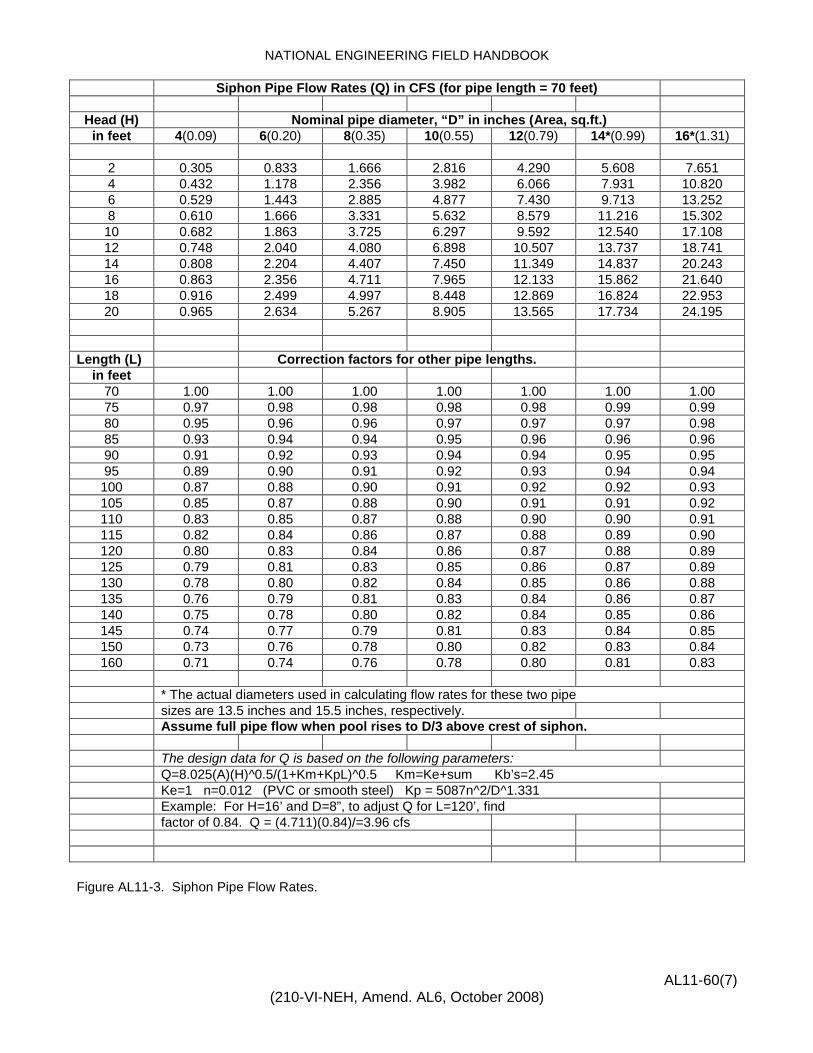
Siphon Pipe Flow Rates (Q) in CFS (for pipe length = 70 feet)
Head (H) Nominal pipe diameter, “D” in inches (Area, sq.ft.) in feet 4(0.09) 6(0.20) 8(0.35) 10(0.55) 12(0.79) 14*(0.99) 16*(1.31)
2 0.305 0.833 1.666 2.816 4.290 5.608 7.651 4 0.432 1.178 2.356 3.982 6.066 7.931 10.820 6 0.529 1.443 2.885 4.877 7.430 9.713 13.252 8 0.610 1.666 3.331 5.632 8.579 11.216 15.302 10 0.682 1.863 3.725 6.297 9.592 12.540 17.108 12 0.748 2.040 4.080 6.898 10.507 13.737 18.741 14 0.808 2.204 4.407 7.450 11.349 14.837 20.243 16 0.863 2.356 4.711 7.965 12.133 15.862 21.640 18 0.916 2.499 4.997 8.448 12.869 16.824 22.953 20 0.965 2.634 5.267 8.905 13.565 17.734 24.195
Length (L) Correction factors for other pipe lengths.
in feet 70 1.00 1.00 1.00 1.00 1.00 1.00 1.00 75 0.97 0.98 0.98 0.98 0.98 0.99 0.99 80 0.95 0.96 0.96 0.97 0.97 0.97 0.98 85 0.93 0.94 0.94 0.95 0.96 0.96 0.96 90 0.91 0.92 0.93 0.94 0.94 0.95 0.95 95 0.89 0.90 0.91 0.92 0.93 0.94 0.94 100 0.87 0.88 0.90 0.91 0.92 0.92 0.93 105 0.85 0.87 0.88 0.90 0.91 0.91 0.92 110 0.83 0.85 0.87 0.88 0.90 0.90 0.91 115 0.82 0.84 0.86 0.87 0.88 0.89 0.90 120 0.80 0.83 0.84 0.86 0.87 0.88 0.89 125 0.79 0.81 0.83 0.85 0.86 0.87 0.89 130 0.78 0.80 0.82 0.84 0.85 0.86 0.88 135 0.76 0.79 0.81 0.83 0.84 0.86 0.87 140 0.75 0.78 0.80 0.82 0.84 0.85 0.86 145 0.74 0.77 0.79 0.81 0.83 0.84 0.85 150 0.73 0.76 0.78 0.80 0.82 0.83 0.84 160 0.71 0.74 0.76 0.78 0.80 0.81 0.83
* The actual diameters used in calculating flow rates for these two pipe sizes are 13.5 inches and 15.5 inches, respectively. Assume full pipe flow when pool rises to D/3 above crest of siphon. The design data for Q is based on the following parameters: Q=8.025(A)(H)^0.5/(1+Km+KpL)^0.5 Km=Ke+sum Kb’s=2.45 Ke=1 n=0.012 (PVC or smooth steel) Kp = 5087n^2/D^1.331 Example: For H=16’ and D=8”, to adjust Q for L=120’, find factor of 0.84. Q = (4.711)(0.84)/=3.96 cfs Figure AL11-3. Siphon Pipe Flow Rates.


NATIONAL ENGINEERING FIELD HANDBOOK
PONDS
A. Engineering Surveys for Design and Construction Layout (SCS-
ENG-28 and 29 - Loose Leafs)
1. Complete title page (SCS-ENG-28) with sketch of practice location.
2. Show at beginning of survey: farmer’s name, purpose of survey, name of practice, party members, duties, and date.
3. Describe benchmark. 4. Close out survey within allowable limits. 5. Soil borings. 6. Complete design date including placement of spoil and
vegetative needs. 7. Include in surveys: cross section, pipe elevations, waterline,
and stakes for construction. 8. Design approval and date. 9. Review General Manual 450-407 for all components.
B. Construction and Performance Check (SCS-ENG-29 - Loose Leafs)
1. Use Pond Construction Check Data Form. 2. Make profile along centerline of top of completed dam. 3. Cross-section at one or more locations of the completed dam. 4. Profile and cross section of completed spillway. 5. Elevation of completed riser and invert of barrel at outlet end of
pipe spillway. 6. Statement of depth and area of normal pool if part of
specifications. 7. Other items as specified by General Manual 450-407. 8. General remarks and certification that practice meets
construction plans and specifications.
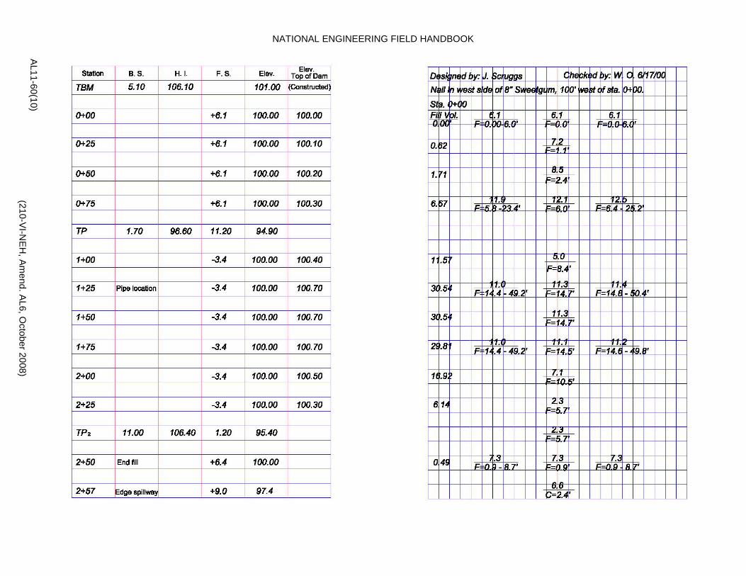
Figure AL11-4. Design and construction layout survey notes for earth fill pond. (Sheet 1 of 4)
AL11-60(8) (210-VI-N
EH, Am
end. AL6, O
ctober 2008)


NATIONAL ENGINEERING FIELD HANDBOOK
AL11-60(9) (210-VI-N
EH, Am
end. AL6, O
ctober 2008)
LOCATION SKETCH DATE 1-00 • PHOTOGRAPH NO. R-22 BY JLD
SOIL BORINGS
HOLES 1 2 3 4 5 6 7 DEPTH
1 SM SM SM SM SM 2 SC SC SM SM SP 3 SC SC SC SC SM 4 SC SC SC SC SC
REMARKS: Material is good for pond site. Salvage topsoil for reuse.
U.S. Dept. of Agriculture AL-ENG-17 Natural Resources Conservation Service Rev. 9/99

Figure AL11-4. Design and Construction layout survey notes for earth fill pond. (Sheet 2 of 4)
NATIONAL ENGINEERING FIELD HANDBOOK
AL11-60(10) (210-VI-N
EH, Am
end. AL6, O
ctober 2008)

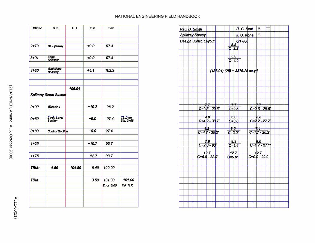
Figure AL11-4. Design and construction layout survey notes for earth fill ponds. (Sheet 3 of 4)
NATIONAL ENGINEERING FIELD HANDBOOK
AL11-60(11) (210-VI-N
EH, Am
end. AL6, O
ctober 2008)

Figure AL11-4. Design and construction layout survey notes for earth fill pond. (Sheet 4 of 4)

NATIONAL ENGINEERING FIELD HANDBOOK
AL11-60(12) (210-VI-N
EH, Am
end. AL6, O
ctober 2008)

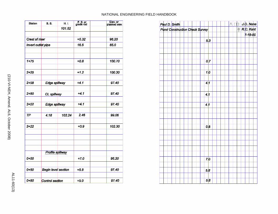
Figure AL11-5. Construction check survey notes for earth fill pond. (Sheet 1 of 3)
NATIONAL ENGINEERING FIELD HANDBOOK
AL11-60(13) (210-VI-N
EH, Am
end. AL6, O
ctober 2008)
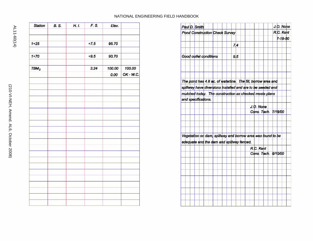
Figure AL11-5. Construction check survey notes for earth fill pond. (Sheet 2 of 3)
NATIONAL ENGINEERING FIELD HANDBOOK
AL11-60(14) (210-VI-N
EH, Am
end. AL6, O
ctober 2008)

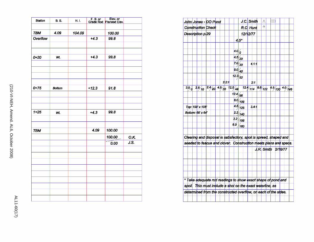
Figure AL11-5. Construction check survey notes for earth fill pond. (Sheet 3 of 3)

NATIONAL ENGINEERING FIELD HANDBOOK
EXCAVATED PONDS
A. Engineering Surveys for Design and Construction Layout (SCS-ENG-28 and 29 - Loose Leaf Notes) 1. Complete title page with sketch of practice location. 2. Show at beginning of survey; farmer’s name, purpose of survey,
name of practice, party members, duties, and date. 3. Describe benchmark. 4. Close out survey within allowable limits. 5. Soil borings. 6. Complete design data including placement of spoil and
vegetative needs. 7. Include in surveys; cross sections, bottom elevation, and stake
for construction. 8. Design approved and checked. B. Construction and Performance Check (SCS-ENG-29 - Loose Leaf Notes) 1. Survey cross sections showing side slopes, depth with
measurements of length and width of pond. 2. When spoil is placed in a dam, show differential elevations
between by-pass and top of dam. 3. Supporting statements.
a. Placement and disposal of spoil. b. Condition of clearing disposal. c. Condition of vegetation. d. General remarks about construction meeting plans and
specifications along with signature, title, and dates.
AL11-60(15) (210-VI-N
EH, Am
end. AL6, O
ctober 2008)

Figure AL11-6. Design - Construction layout survey notes for excavated pond. (Sheet 1 of 3)
U.S. DEPT. OF AGRICULTURE AL-ENG-6 Natural Resources Conservation Service Rev. 9/99
DUG POND DESIGN DATA
IF STANDARDIZED DESIGN, CHECK HERE JOB CLASS I DRAINAGE AREA 2 AC. SOIL SERIES Melvin CATTLE 30 HEAD 180 DAYS OR 6 MONTHS CATTLE NEEDS = 0.249 AF. LOSSES = 0.821 AF. STORAGE REQ’D = 0.249 + 0.821 = 1.070 AF. SURFACE SIZE = 100 x 100 FT. S. SLOPES 2 :1 END SLOPES 4 :1 & 3 :1 DEPTH 8 FT. DESIGNED STORAGE = 1.138 AF. YARDAGE = 1836 BOT. SIZE = 44 x 68 FT. SPOIL IS TO BE shaped on 3 sides SEEDED TO fescue/clover with mulch DESIGNED BY J.R.S. CHECKED BY R.G.H.
LOCATION SKETCH DATE 1-00 • PHOTOGRAPH NO. R-22 BY JLD
SOIL BORINGS
HOLES 1 2 3 4 5 6 7 DEPTH
1 SM SM SM SM SM 2 SC SC SM SM SP 3 SC SC SC SC SM 4 SC SC SC SC SC
REMARKS: The site should hold water and is fed by a small underground seep flow.
U.S. Dept. of Agriculture AL-ENG-17 Natural Resources Conservation Service Rev. 9/99
AL11-60(16) (210-VI-N
EH, Am
end. AL6, O
ctober 2008)

Figure AL11-6. Design - construction layout survey notes for excavated pond. (Sheet 2 of 3)

NATIONAL ENGINEERING FIELD HANDBOOK
AL11-60(17) (210-VI-N
EH, Am
end. AL6, O
ctober 2008)

Figure AL11-6. Design - Construction layout survey notes for excavated pond. Sheet 3 of 3


Smooth Pipe (inches) Corrugated Pipe (inches)
Barrel Diam. 4 6 8 10 12 15 18 24 30 6 8 10 12 15 18 24 30
Riser Diam. 6 *Use Figure AL11-8A 8 10 * Use Figure AL11-8a
Head in Feet
0.8 1.8 3.4 5.7 8.3 14.1 24.6 40.7 65.0 1.0 2.1 3.7 5.7 10.2 15.7 31.4 53.0 6
7 0.8 1.8 3.6 5.9 8.6 14.9 24.9 42.8 69.1 1.0 2.1 3.8 5.8 10.5 16.3 32.6 55.2
8 0.9 1.8 3.7 6.1 8.9 15.3 25.3 45.0 73.2 1.1 2.2 3.9 5.9 10.7 16.9 33.8 57.5
9 0.9 1.8 3.8 6.4 9.2 15.8 25.7 46.9 76.5 1.1 2.2 4.0 6.1 11.0 17.3 34.8 59.3
10 1.0 1.9 3.9 6.6 9.6 16.4 26.1 48.7 79.7 1.1 2.3 4.1 6.2 11.3 17.7 35.8 61.1
11 1.0 1.9 4.0 6.8 9.9 17.0 26.6 50.3 82.6 1.1 2.3 4.1 6.4 11.6 18.1 36.7 62.7
12 1.1 2.0 4.1 7.0 10.2 17.6 27.0 52.0 85.1 1.1 2.4 4.2 6.5 11.8 18.5 37.5 64.2
13 1.1 2.0 4.2 7.2 10.5 18.1 27.2 53.3 87.4 1.2 2.4 4.3 6.6 12.0 18.7 38.1 65.4
14 1.2 2.1 4.3 7.5 10.8 18.7 27.5 54.6 89.7 1.2 2.5 4.4 6.8 12.3 19.0 38.7 66.5
15 1.2 2.1 4.4 7.7 11.2 19.3 27.6 57.0 93.8 1.2 2.5 4.5 6.9 12.6 19.7 40.1 69.2
16 1.3 2.2 4.5 7.9 11.5 19.9 27.8 59.4 97.9 1.2 2.6 4.6 7.0 12.9 20.4 41.6 71.9
17 1.3 2.2 4.7 8.1 11.8 20.5 28.1 60.9 100.4 1.3 2.6 4.7 7.1 13.2 20.6 42.3 73.2
18 1.4 2.3 4.8 8.3 12.1 21.0 28.4 62.4 103.0 1.3 2.7 4.8 7.3 13.4 20.9 43.0 74.5
19 1.4 2.3 4.9 8.6 12.4 21.6 28.7 63.6 105.1 1.3 2.7 4.9 7.5 13.7 21.1 43.6 75.0
20 1.5 2.4 5.0 8.8 12.7 22.2 29.0 64.8 107.1 1.4 2.8 4.9 7.6 13.9 21.4 44.2 75.6
* Select riser using procedure outlined in Chapter 6 or Figure AL11-8a.
T (Time) = 12.1 x Vs/Qo
Table AL11-2. Discharge in cubic feet per second (CFS) for pipe conduit with different heads.
AL11-60(18) (210-VI-N
EH, Am
end. AL6, O
ctober 2008)

AL11-60(19) (210-VI-NEH, Amend. AL6, October 2008)
TABLE OF WEIGHTS AND BUOYANT FORCES FOR CORRUGATED METAIL, STEEL, AND PLASTIC PIPE Based on U.S. Standard Gages for Sheet and Plate Iron and Steel
Nominal Dia. In inches
WEIGHT (W) - POUNDS PER LINEAR FOOT 1/ Buoyant Force (B)
in lbs. per lin.ft.
CORRUGATED METAL SMOOTH STEEL PVC
GAGE Wall Thickness 2/ SDR-26 Sch. -40 Sch. -80 16 14 12 10 1/8 “ 1/4 “ 1/2 ”
6 4.0 8.8 14.7 32.8 2.4 12.3 8 7.3/2.3* 11.7 19.6 43.4 3.7 21.8
10 9.0/2.8 14.7 24.5 54.7 5.8 34.0 12 10.5/3.3 12.0/4.1 17.7 29.4 65.6 8.0 49.0 15 12.9/4.1 15.0/5.1 22.1 36.8 82.1 11.2 76.6 18 15.3/4.8 18.0/6.0 24.0/8.4 26.5 44.2 98.5 16.0 110.3 21 17.7/5.6 21.0/7.0 29.0/9.7 30.9 51.5 114.9 21.2 150.1 24 20.0/6.2 25.2/8.0 33.0/11.2 35.3 58.9 131.3 28.5 196.1 30 30.9/9.8 41.0/13.7 44.2 73.6 164.1 43.7 306.3 36 51.0/16.4 62.0/21.1 53.0 88.4 197.0 64.5 441.1 42 59.5/19.2 72.0/24.7 61.8 103.1 229.8 87.2 600.4 48 65.0/22.4 82.0/28.8 70.7 117.8 262.6 110.4 783.7
* Corrugated galvanized steel/corrugated aluminum (pounds per linear foot) 1/ Use these values when weight is not available from manufacturer. 2/ For steel pipe wall thickness of 3/16” and 3/8”, interpolate weight/foot from table. Check for riser flotation: Given: Corrugated steel pipe riser 62.4 lb/cu.ft. = unit weight of water Diameter = 18 in., 16 gage h = Height = 15 feet 150.0 lb/cu.ft. = unit weight of concrete No fill over outlet pipe From table: W = Weight = 15.3 pounds/linear foot B = Buoyancy = 110.3 pounds/linear foot Required volume of concrete: (At riser base) (B-W)h = (110.3 - 15.3)15 = 16.3 cu.ft. 87.6 87.6 NOTES: (1) Weight of submerged concrete = 150 lb/cu.ft.
-62.4 lb/cu.ft. = 87.6 lb/cu.ft. Factor of safety - 1.0. Therefore, 87.6 / 1.0 = 87.6 lb./cu.ft.
(2) Factor of safety of 1.0 was used due to
weight of trash rack or sleeve and bending force as the result of barrel being imbedded in the dam. Riser placed in the dam with 5 feet of fill over outlet pipe requires no check of buoyant forces.
Table AL11-3. Weights and Buoyant Forces for Corrugated Metal, Steel, and Plastic Pipe.


AL11-60(20) (210-VI-NEH, Amend. AL6, October 2008)
Riser Base Size
MAXIMUM RISER HEIGHT (FT.)
Riser Diameter (inches)
42 36 30 24 21 18
3’ x 3’ x 2’ 6.0 7.9 11.1
3 ½ ‘ x 3 ½ ‘ x 2’ 5.2 8.1 10.8 15.1
3’ x 3’ x 3’ 5.7 9.0 11.9
4’ x 4’ x 2’ 6.8 10.6 14.1
3’ x 3’ x 4’ 5.2 7.6 12.0 15.9
3 ½ ‘ x 3 ½ ‘ x 3’ 5.3 7.8 12.2 16.2
4’ x 4’ x 3’ 5.0 6.9 10.2 16.0
3 ½ ‘ x 3 ½ ‘ x 4’ 5.1 7.1 10.3 16.3
4’ x 4’ x 4’ 6.7 9.3 13.6
5’ x 5’ x 4’ 10.4 14.5
5’ x 5’ x 5’ 13.1 NOTE: Riser Diameters Less than 18 in. Use Minimum Size Riser Base 3’ x 3’ x 2’. Resource Engineer may approve smaller riser bases for riser diameter less than 18 in. according to
actual on-site conditions and buoyance calculations. Table AL11-4. Minimum Riser Base Size to Prevent Flotation.


AL11-60(21) (210-VI-NEH, Amend. AL6, October 2008)
FILL HEIGHT
SIDE SLOPES 2 ½ : 1 AND 2 ½ : 1 TOP WIDTH (feet)
8 10 12 14 0.1 0.03 0.04 0.05 0.05 0.2 0.06 0.08 0.09 0.11 0.3 0.09 0.12 0.14 0.16 0.4 0.13 0.16 0.19 0.22 0.5 0.17 0.21 0.25 0.28 0.6 0.21 0.26 0.30 0.34 0.7 0.25 0.30 0.36 0.41 0.8 0.30 0.36 0.41 0.47 0.9 0.35 0.41 0.47 0.54 1.0 0.39 0.46 0.54 0.61 1.1 0.44 0.52 0.60 0.68 1.2 0.49 0.58 0.67 0.76 1.3 0.54 0.64 0.73 0.83 1.4 0.60 0.70 0.80 0.91 1.5 0.66 0.76 0.87 0.99 1.6 0.71 0.83 0.95 1.07 1.7 0.77 0.90 1.02 1.15 1.8 0.83 0.97 1.10 1.23 1.9 0.90 1.04 1.18 1.32 2.0 0.96 1.11 1.26 1.41 2.1 1.03 1.19 1.34 1.50 2.2 1.10 1.26 1.43 1.59 2.3 1.17 1.34 1.51 1.68 2.4 1.24 1.42 1.60 1.78 2.5 1.32 1.50 1.69 1.87 2.6 1.40 1.59 1.78 1.97 2.7 1.48 1.67 1.87 2.07 2.8 1.56 1.76 1.97 2.18 2.9 1.64 1.85 2.07 2.28 3.0 1.72 1.94 2.17 2.39 3.1 1.81 2.04 2.27 2.50 3.2 1.90 2.13 2.37 2.61 3.3 1.99 2.23 2.47 2.72 3.4 2.08 2.33 2.58 2.83 3.5 2.17 2.43 2.69 2.95 3.6 2.27 2.53 2.80 3.07 3.7 2.36 2.64 2.91 3.19 3.8 2.46 2.74 3.03 3.31 3.9 2.56 2.85 3.14 3.43 4.0 2.67 2.96 3.26 3.56 4.1 2.78 3.07 3.38 3.68 4.2 2.88 3.19 3.50 3.81 4.3 2.99 3.30 3.62 3.94 4.4 3.10 3.42 3.75 4.07 4.5 3.21 3.54 3.87 4.21 4.6 3.32 3.66 4.00 4.34 4.7 3.44 3.79 4.13 4.48 4.8 3.56 3.91 4.27 4.62 4.9 3.68 4.04 4.40 4.76 5.0 3.80 4.17 4.54 4.91
FILL HEIGHT
SIDE SLOPES 2 ½ : 1 AND 2 ½ : 1 TOP WIDTH (feet)
8 10 12 14 5.1 3.92 4.30 4.67 5.05 5.2 4.04 4.43 4.81 5.20 5.3 4.17 4.56 4.96 5.35 5.4 4.30 4.70 5.10 5.50 5.5 4.43 4.84 5.25 5.65 5.6 4.56 4.98 5.39 5.81 5.7 4.69 5.12 5.54 5.96 5.8 4.83 5.26 5.69 6.12 5.9 4.97 5.41 5.85 6.28 6.0 5.11 5.56 6.00 6.44 6.1 5.25 5.70 6.16 6.61 6.2 5.40 5.86 6.31 6.77 6.3 5.54 6.01 6.47 6.94 6.4 5.69 6.16 6.64 7.11 6.5 5.84 6.32 6.80 7.28 6.6 5.99 6.48 6.97 7.46 6.7 6.14 6.64 7.13 7.63 6.8 6.30 6.80 7.30 7.81 6.9 6.46 6.96 7.47 7.99 7.0 6.61 7.13 7.65 8.17 7.1 6.77 7.30 7.82 8.35 7.2 6.93 7.47 8.00 8.53 7.3 7.10 7.64 8.18 8.72 7.4 7.26 7.81 8.36 8.91 7.5 7.43 7.99 8.54 9.10 7.6 7.60 8.16 8.73 9.29 7.7 7.77 8.34 8.91 9.48 7.8 7.94 8.52 9.10 9.68 7.9 8.12 8.70 9.29 9.87 8.0 8.30 8.89 9.48 10.07 8.1 8.48 9.07 9.67 10.27 8.2 8.66 9.26 9.87 10.48 8.3 8.84 9.45 10.07 10.68 8.4 9.02 9.64 10.27 10.89 8.5 9.21 9.84 10.47 11.10 8.6 9.40 10.03 10.67 11.31 8.7 9.59 10.23 10.87 11.52 8.8 9.78 10.43 11.08 11.73 8.9 9.97 10.63 11.29 11.95 9.0 10.17 10.83 11.50 12.17 9.1 10.36 11.04 11.71 12.39 9.2 10.56 11.24 11.93 12.61 9.3 10.76 11.45 12.14 12.83 9.4 10.97 11.66 12.36 13.06 9.5 11.18 11.87 12.58 13.29 9.6 11.38 12.09 12.80 13.51 9.7 11.59 12.30 13.02 13.74 9.8 11.80 12.52 13.25 13.97 9.9 12.01 12.74 13.47 14.21 10.0 12.22 12.96 13.70 14.44
(Sheet 1 of 8) Table AL11-5. End area tables for earthfill dams cubic yards per foot for embankment.


AL11-60(22) (210-VI-NEH, Amend. AL6, October 2008)
FILL HEIGHT
SIDE SLOPES 2 ½ : 1 AND 2 ½ : 1 TOP WIDTH (feet)
10 12 14 10.1 13.19 13.93 14.68 10.2 13.41 14.17 14.92 10.3 13.64 14.40 15.16 10.4 13.87 14.64 15.41 10.5 14.10 14.87 15.65 10.6 14.33 15.11 15.90 10.7 14.56 15.36 16.15 10.8 14.80 15.60 16.40 10.9 15.04 15.85 16.65 11.0 15.28 16.09 16.91 11.1 15.52 16.34 17.16 11.2 15.76 16.59 17.42 11.3 16.01 16.85 17.68 11.4 16.26 17.10 17.94 11.5 16.50 17.36 18.21 11.6 16.76 17.61 18.47 11.7 17.01 17.87 18.74 11.8 17.26 18.14 19.01 11.9 17.52 18.40 19.28 12.0 17.78 18.67 19.56 12.1 18.04 18.93 19.83 12.2 18.30 19.20 20.11 12.3 18.56 19.47 20.39 12.4 18.83 19.75 20.67 12.5 19.10 20.02 20.95 12.6 19.37 20.30 21.23 12.7 19.64 20.58 21.52 12.8 19.91 20.86 21.81 12.9 20.19 21.14 22.10 13.0 20.46 21.43 22.39 13.1 20.74 21.71 22.68 13.2 21.02 22.00 22.98 13.3 21.30 22.29 23.27 13.4 21.59 22.58 23.57 13.5 21.87 22.87 23.87 13.6 22.16 23.17 24.18 13.7 22.45 23.47 24.48 13.8 22.74 23.77 24.79 13.9 23.04 24.07 25.10 14.0 23.33 24.37 25.41 14.1 23.63 24.67 25.72 14.2 23.93 24.98 26.03 14.3 24.23 25.29 26.35 14.4 24.53 25.60 26.67 14.5 24.84 25.91 26.99 14.6 25.14 26.23 27.31 14.7 25.45 26.54 27.63 14.8 25.76 26.86 27.96 14.9 26.07 27.18 28.28 15.0 26.39 27.50 28.61
FILL HEIGHT
SIDE SLOPES 2 ½ : 1 AND 2 ½ : 1 TOP WIDTH (feet)
10 12 14 15.1 26.70 27.82 28.94 15.2 27.02 28.15 29.27 15.3 27.34 28.47 29.61 15.4 27.66 28.80 29.94 15.5 27.99 29.13 30.28 15.6 28.31 29.47 30.62 15.7 28.64 29.80 30.96 15.8 28.97 30.14 31.31 15.9 29.30 30.47 31.65 16.0 29.63 30.81 32.00 16.1 29.96 31.16 32.35 16.2 30.30 31.50 32.70 16.3 30.64 31.85 33.05 16.4 30.98 32.19 33.41 16.5 31.32 32.54 33.76 16.6 31.66 32.89 34.12 16.7 32.01 33.25 34.48 16.8 32.36 33.60 34.84 16.9 32.70 33.96 35.21 17.0 33.06 34.31 35.57 17.1 33.41 34.67 35.94 17.2 33.76 35.04 36.31 17.3 34.12 35.40 36.68 17.4 34.48 35.77 37.06 17.5 34.84 36.13 37.43 17.6 35.20 36.50 37.81 17.7 35.56 36.87 38.19 17.8 35.93 37.25 38.57 17.9 36.30 37.62 38.95 18.0 36.67 38.00 39.33 18.1 37.04 38.38 39.72 18.2 37.41 38.76 40.11 18.3 37.79 39.14 40.50 18.4 38.16 39.53 40.89 18.5 38.54 39.91 41.28 18.6 38.92 40.30 41.88 18.7 39.30 40.69 42.07 18.8 39.69 41.08 42.47 18.9 40.07 41.47 42.87 19.0 40.46 41.87 43.28 19.1 40.85 42.27 43.88 19.2 41.24 42.67 44.09 19.3 41.64 43.07 44.50 19.4 42.03 43.47 44.91 19.5 42.43 43.87 45.32 19.6 42.83 44.28 45.73 19.7 43.23 44.69 46.15 19.8 43.63 45.10 46.57 19.9 44.04 45.51 46.99 20.0 44.44 45.93 47.41
(Sheet 2 of 8)
Table AL11-5. End area tables for earthfill dams cubic yards per foot for embankment.


AL11-60(23) (210-VI-NEH, Amend. AL6, October 2008)
FILL HEIGHT
SIDE SLOPES 2 ½ : 1 AND 2 ½ : 1 TOP WIDTH (feet)
10 12 14 20.1 44.85 46.34 47.83 20.2 45.26 46.76 48.26 20.3 45.67 47.18 48.68 20.4 46.09 47.60 49.11 20.5 46.50 48.02 49.54 20.6 46.92 48.45 49.97 20.7 47.34 48.87 50.41 20.8 47.76 49.30 50.84 20.9 48.19 49.73 51.28 21.0 48.61 50.17 51.72 21.1 49.04 50.60 52.16 21.2 49.47 51.04 50.61 21.3 49.90 51.47 53.05 21.4 50.33 51.91 53.50 21.5 50.76 52.36 53.95 21.6 51.20 52.80 54.40 21.7 51.64 53.25 54.85 21.8 52.08 53.69 55.31 21.9 52.52 54.14 55.76 22.0 52.96 54.59 56.22 22.1 53.41 55.05 56.68 22.2 53.86 55.50 57.14 22.3 54.30 55.96 57.61 22.4 54.76 56.41 58.07 22.5 55.21 56.87 58.54 22.6 55.66 57.34 59.01 22.7 56.12 57.80 59.48 22.8 56.58 58.27 59.96 22.9 57.04 58.73 60.43 23.0 57.50 59.20 60.91 23.1 57.96 59.67 61.39 23.2 58.43 60.15 61.87 23.3 58.90 60.62 62.35 23.4 59.37 61.10 62.83 23.5 59.84 61.58 63.32 23.6 60.31 62.06 63.81 23.7 60.79 62.54 64.30 23.8 61.26 63.03 64.79 23.9 61.74 63.51 65.28 24.0 62.22 64.00 65.78 24.1 62.70 64.49 66.27 24.2 63.19 64.98 66.77 24.3 63.67 65.47 67.27 24.4 64.16 65.97 67.78 24.5 64.65 66.47 68.28 24.6 65.14 66.97 68.79 24.7 65.64 67.47 69.30 24.8 66.13 67.97 69.81 24.9 66.63 68.47 70.32 25.0 67.13 68.98 70.83
FILL HEIGHT
SIDE SLOPES 2 ½ : 1 AND 2 ½ : 1 TOP WIDTH (feet)
10 12 14 25.1 67.63 89.49 71.35 25.2 68.13 70.00 71.87 25.3 68.64 70.51 72.39 25.4 69.14 71.03 72.91 25.5 69.65 71.54 73.43 25.6 70.16 72.06 73.96 25.7 70.67 72.58 74.48 25.8 71.19 73.10 75.01 25.9 71.70 73.62 75.54 26.0 72.22 74.15 76.07 26.1 72.74 74.67 76.61 26.2 73.26 75.20 77.14 26.3 73.79 75.73 77.68 26.4 74.31 76.27 78.22 26.5 74.84 76.80 78.76 26.6 75.37 77.34 79.31 26.7 75.90 77.87 79.85 26.8 76.43 78.41 80.40 26.9 76.96 78.96 80.95 27.0 77.50 79.50 81.50 27.1 78.04 80.05 82.05 27.2 78.58 80.59 82.61 27.3 79.12 81.14 93.16 27.4 79.66 81.69 83.72 27.5 80.21 82.25 84.28 27.6 80.76 82.80 84.84 27.7 81.30 83.36 85.41 27.8 81.86 83.91 85.97 27.9 82.41 84.47 86.54 28.0 82.96 85.04 87.11 28.1 83.52 85.60 87.68 28.2 84.08 86.17 88.26 28.3 84.64 86.73 88.83 28.4 85.20 87.30 89.41 28.5 85.76 87.87 89.99 28.6 86.33 88.45 90.57 28.7 86.90 89.02 91.15 28.8 87.47 89.60 91.73 28.9 88.04 90.18 92.32 29.0 88.61 90.76 92.91 29.1 89.19 91.34 93.50 29.2 89.76 91.93 94.09 29.3 90.34 92.51 94.68 29.4 90.92 93.10 95.28 29.5 91.50 93.69 95.87 29.6 92.09 94.28 96.47 29.7 92.67 94.87 97.07 29.8 93.26 95.47 97.68 29.9 93.85 96.07 98.28 30.0 94.44 96.67 98.89
(Sheet 3 of 8) Table AL11-5. End area tables for earthfill dams cubic yards per foot for embankment.


AL11-60(24) (210-VI-NEH, EFH, Amend. AL6, October 2008)
FILL HEIGHT
SIDE SLOPES 2 ½ : 1 AND 2 ½ : 1 TOP WIDTH (feet)
10 12 14 30.1 95.04 97.27 99.50 30.2 95.63 97.87 100.11 30.3 96.23 98.47 100.72 30.4 96.83 99.08 101.33 30.5 97.43 99.69 101.95 30.6 98.03 100.30 102.57 30.7 98.64 100.91 103.19 30.8 99.24 101.53 103.81 30.9 99.85 102.14 104.43 31.0 100.46 102.76 105.06 31.1 101.07 103.38 105.68 31.2 101.69 104.00 106.31 31.3 102.30 104.62 106.94 31.4 102.92 105.25 107.57 31.5 103.54 105.87 108.21 31.6 104.16 106.50 108.84 31.7 104.79 107.13 109.48 31.8 105.41 107.77 111.12 31.9 106.04 108.40 111.76 32.0 106.67 109.04 111.41 32.1 107.30 109.67 112.05 32.2 107.93 110.31 112.70 32.3 108.56 110.96 113.35 32.4 109.20 111.60 114.00 32.5 109.84 112.25 114.65 32.6 110.48 112.89 115.31 32.7 111.12 113.54 115.96 32.8 111.76 114.19 116.62 32.9 112.41 114.85 117.28 33.0 113.06 115.50 117.94 33.1 113.70 116.16 118.61 33.2 114.36 116.81 119.27 33.3 115.01 117.47 119.94 33.4 115.66 118.14 120.61 33.5 116.32 118.80 121.28 33.6 116.98 119.47 121.96 33.7 117.64 120.13 122.63 33.8 118.30 120.80 123.31 33.9 118.96 121.47 123.99 34.0 119.63 122.15 124.67 34.1 120.30 122.82 125.35 34.2 120.97 123.50 126.03 34.3 121.64 124.18 126.72 34.4 122.31 124.86 127.41 34.5 122.99 125.54 128.10 34.6 123.66 126.23 128.79 34.7 124.34 126.91 129.48 34.8 125.02 127.60 130.18 34.9 125.70 128.29 130.87 35.0 126.39 128.98 131.57
FILL HEIGHT
SIDE SLOPES 2 ½ : 1 AND 2 ½ : 1 TOP WIDTH (feet)
10 12 14 35.1 127.07 129.67 132.27 35.2 127.76 130.37 132.98 35.3 128.45 131.07 133.68 35.4 129.14 131.77 134.39 35.5 129.84 132.47 135.10 35.6 130.53 133.17 135.81 35.7 131.23 133.87 136.52 35.8 131.93 134.58 137.23 35.9 132.63 135.29 137.95 36.0 133.33 136.00 138.67 36.1 134.04 136.71 139.39 36.2 134.74 137.43 140.11 36.3 135.45 138.14 140.83 36.4 136.16 138.86 141.56 36.5 136.87 139.58 142.28 36.6 137.59 140.30 143.01 36.7 138.30 141.02 143.74 36.8 139.02 141.75 144.47 36.9 139.74 142.47 145.21 37.0 140.46 143.20 145.94 37.1 141.19 143.93 146.88 37.2 141.91 144.67 147.42 37.3 142.64 145.40 148.16 37.4 143.37 146.14 148.91 37.5 144.10 146.87 149.65 37.6 144.83 147.61 150.40 37.7 145.56 148.36 151.15 37.8 146.30 149.10 151.90 37.9 147.04 149.85 152.65 38.0 147.78 150.59 153.41 38.1 148.52 151.34 154.18 38.2 149.26 152.09 154.92 38.3 150.01 152.85 155.68 38.4 150.76 153.60 156.44 38.5 151.50 154.36 157.21 38.6 152.26 155.11 157.97 38.7 153.01 155.87 158.74 38.8 153.76 156.64 159.51 38.9 154.52 157.40 160.28 39.0 155.28 158.17 161.06 39.1 156.04 158.93 161.83 39.2 156.80 159.70 162.61 39.3 157.56 160.47 163.39 39.4 158.33 161.25 164.17 39.5 159.10 162.02 164.95 39.6 159.87 162.80 165.73 39.7 160.64 163.58 166.52 39.8 161.41 164.36 167.31 39.9 162.19 165.14 168.10 40.0 162.96 165.93 168.89
(Sheet 4 of 8) Table AL11-5. End area tables for earthfill dams cubic yards per foot for embankment.


AL11-60(25) (210-VI-NEH, EFH, Amend. AL6, October 2008)
FILL HEIGHT
SIDE SLOPES 3:1 AND 3:1 TOP WIDTH (feet)
8 10 12 14 0.1 0.03 0.04 0.05 0.05 0.2 0.06 0.08 0.09 0.11 0.3 0.10 0.12 0.14 0.17 0.4 0.14 0.17 0.20 0.23 0.5 0.18 0.21 0.25 0.29 0.6 0.22 0.26 0.31 0.35 0.7 0.26 0.31 0.37 0.42 0.8 0.31 0.37 0.43 0.49 0.9 0.36 0.42 0.49 0.56 1.0 0.41 0.48 0.56 0.63 1.1 0.46 0.54 0.62 0.70 1.2 0.52 0.60 0.69 0.78 1.3 0.57 0.67 0.77 0.86 1.4 0.63 0.74 0.84 0.94 1.5 0.69 0.81 0.92 1.03 1.6 0.76 0.88 1.00 1.11 1.7 0.83 0.95 1.08 1.20 1.8 0.89 1.03 1.16 1.29 1.9 0.96 1.10 1.25 1.39 2.0 1.04 1.19 1.33 1.48 2.1 1.11 1.27 1.42 1.58 2.2 1.19 1.35 1.52 1.68 2.3 1.27 1.44 1.61 1.78 2.4 1.35 1.53 1.71 1.88 2.5 1.43 1.62 1.81 1.99 2.6 1.52 1.71 1.91 2.10 2.7 1.61 1.81 2.01 2.21 2.8 1.70 1.91 2.12 2.32 2.9 1.79 2.01 2.22 2.44 3.0 1.89 2.11 2.33 2.56 3.1 1.99 2.22 2.45 2.68 3.2 2.09 2.32 2.56 2.80 3.3 2.10 2.43 2.68 2.92 3.4 2.30 2.54 2.80 3.05 3.5 2.40 2.66 2.92 3.18 3.6 2.51 2.77 3.04 3.31 3.7 2.62 2.89 3.17 3.44 3.8 2.73 3.01 3.29 3.57 3.9 2.85 3.13 3.42 3.71 4.0 2.96 3.26 3.56 3.85 4.1 3.08 3.39 3.69 3.99 4.2 3.20 3.52 3.83 4.14 4.3 3.32 3.65 3.97 4.28 4.4 3.45 3.78 4.11 4.43 4.5 3.58 3.92 4.25 4.58 4.6 3.71 4.05 4.40 4.74 4.7 3.84 4.20 4.54 4.89 4.8 3.98 4.34 4.69 5.05 4.9 4.12 4.48 4.85 5.21 5.0 4.26 4.63 5.00 5.37
FILL HEIGHT
SIDE SLOPES 3:1 AND 3:1 TOP WIDTH (feet)
8 10 12 14 5.1 4.40 4.78 5.16 5.53 5.2 4.55 4.93 5.32 5.70 5.3 4.70 5.08 5.48 5.87 5.4 4.84 5.24 5.64 6.04 5.5 4.99 5.40 5.81 6.21 5.6 5.14 5.56 5.97 6.39 5.7 5.30 5.72 6.14 6.57 5.8 5.46 5.89 6.32 6.75 5.9 5.62 6.05 6.49 6.93 6.0 5.78 6.22 6.67 7.11 6.1 5.94 6.39 6.85 7.30 6.2 6.11 6.57 7.03 7.49 6.3 6.29 6.74 7.21 7.68 6.4 6.48 6.92 7.40 7.87 6.5 6.64 7.10 7.58 8.06 6.6 6.80 7.28 7.77 8.26 6.7 6.97 7.47 7.97 8.46 6.8 7.15 7.66 8.16 8.66 6.9 7.34 7.85 8.36 8.87 7.0 7.52 8.04 8.56 9.07 7.1 7.71 8.23 8.76 9.28 7.2 7.89 8.43 8.96 9.49 7.3 8.08 8.62 9.17 9.71 7.4 8.28 8.83 9.37 9.92 7.5 8.47 9.03 9.58 10.14 7.6 8.67 9.23 9.80 10.36 7.7 8.87 9.44 10.01 10.58 7.8 9.07 9.65 10.23 10.80 7.9 9.28 9.86 10.45 11.03 8.0 9.48 10.07 10.67 11.26 8.1 9.69 10.29 10.89 11.49 8.2 9.90 10.51 11.12 11.72 8.3 10.11 10.73 11.34 11.96 3.4 10.33 10.95 11.57 12.20 8.5 10.55 11.18 11.81 12.44 8.6 10.77 11.40 12.04 12.68 8.7 10.99 11.63 12.28 12.92 8.8 11.21 11.86 12.52 13.17 8.9 11.44 12.10 12.76 13.42 9.0 11.67 12.33 13.00 13.67 9.1 11.90 12.57 13.25 13.92 9.2 12.13 12.81 13.49 14.17 9.3 12.36 13.05 13.74 14.43 9.4 12.60 13.30 14.00 14.69 9.5 12.84 13.55 14.25 14.95 9.6 13.08 13.80 14.51 15.22 9.7 13.33 14.05 14.77 15.48 9.8 13.57 14.30 15.03 15.75 9.9 13.82 14.56 15.29 16.02 10.0 14.07 14.81 15.56 16.30
(Sheet 5 of 8)
Table AL11-5. End area tables for earthfill dams cubic yards per foot for embankment.


AL11-60(26) (210-VI-NEH, Amend. AL6, October 2008)
FILL HEIGHT
SIDE SLOPES 3:1 AND 3:1 TOP WIDTH (feet)
10 12 14 10.1 15.08 15.82 16.57 10.2 15.34 16.09 16.85 10.3 15.60 16.37 17.13 10.4 15.87 16.64 17.41 10.5 16.14 16.92 17.69 10.6 16.41 17.20 17.98 10.7 16.68 17.48 18.27 10.8 16.96 17.76 18.56 10.9 17.24 18.05 18.85 11.0 17.52 18.33 19.15 11.1 17.80 18.62 19.45 11.2 18.09 18.92 19.75 11.3 18.37 19.21 20.05 11.4 18.66 19.51 20.35 11.5 18.95 19.81 20.66 11.6 19.25 20.11 20.97 11.7 19.54 20.41 21.28 11.8 19.84 20.72 21.59 11.9 20.14 21.02 21.90 12.0 20.44 21.33 22.22 12.1 20.75 21.65 22.54 12.2 21.06 21.96 22.86 12.3 21.37 22.28 23.19 12.4 21.68 22.60 23.51 12.5 21.99 22.92 23.84 12.6 22.31 23.24 24.17 12.7 22.62 23.57 24.51 12.8 22.95 23.89 24.84 12.9 23.27 24.22 25.18 13.0 23.59 24.56 25.52 13.1 23.92 24.89 25.86 13.2 24.25 25.23 26.20 13.3 24.58 25.57 26.55 13.4 24.91 25.91 26.90 13.5 25.25 26.25 27.25 13.6 25.59 26.60 27.60 13.7 25.93 26.94 27.96 13.8 26.27 27.29 28.32 13.9 26.62 27.65 28.68 14.0 26.96 28.00 29.04 14.1 27.31 28.36 29.40 14.2 27.66 28.72 29.77 14.3 28.02 29.08 30.14 14.4 28.37 29.44 30.51 14.5 28.73 29.81 30.88 14.6 29.09 30.17 31.25 14.7 29.45 30.54 31.63 14.8 29.82 30.92 32.01 14.9 30.19 31.29 32.39 15.0 30.56 31.67 32.78
FILL HEIGHT
SIDE SLOPES 3:1 AND 3:1 TOP WIDTH (feet)
10 12 14 15.1 30.93 32.05 33.16 15.2 31.30 32.43 33.55 15.3 31.68 32.81 33.94 15.4 32.05 33.20 34.34 15.5 32.44 33.58 34.73 15.6 32.82 33.97 35.13 15.7 33.20 34.37 35.53 15.8 33.59 34.76 35.93 15.9 33.98 35.16 36.33 16.0 34.37 35.56 36.74 16.1 34.76 35.96 37.15 16.2 35.16 36.36 37.56 16.3 35.56 36.77 37.97 16.4 35.96 37.17 38.39 16.5 36.36 37.58 38.81 16.6 36.77 38.00 39.23 16.7 37.17 38.41 39.65 16.8 37.58 38.83 40.07 16.9 37.99 39.25 40.50 17.0 38.41 39.67 40.93 17.1 38.82 40.09 41.36 17.2 39.24 40.52 41.79 17.3 39.66 40.94 42.22 17.4 40.08 41.37 42.66 17.5 40.51 41.81 43.10 17.6 40.94 42.24 43.54 17.7 41.37 42.68 43.99 17.8 41.80 43.12 44.43 17.9 42.23 43.56 44.88 18.0 42.67 44.00 45.33 18.1 43.10 44.45 45.79 18.2 43.55 44.89 46.24 18.3 43.99 45.34 46.70 18.4 44.43 45.80 47.16 18.5 44.88 46.25 47.62 18.6 45.33 46.71 48.08 18.7 45.78 47.17 48.55 18.8 46.23 47.63 49.02 18.9 46.69 48.09 49.49 19.0 47.15 48.56 49.96 19.1 47.61 49.02 50.44 19.2 48.07 49.49 50.92 19.3 48.54 49.97 51.40 19.4 49.00 50.44 51.88 19.5 49.47 50.92 52.36 19.6 49.94 51.40 52.85 19.7 50.42 51.88 53.34 19.8 50.89 52.36 53.83 19.9 51.37 52.85 54.32 20.0 51.85 53.33 54.81
(Sheet 6 of 8) Table AL11-5. End area tables for earthfill dams cubic yards per foot for embankment.


AL11-60(27) (210-VI-NEH, Amend. AL6, October 2008)
FILL HEIGHT
SIDE SLOPES 3:1 AND 3:1 TOP WIDTH (feet)
10 12 14 20.1 52.33 53.82 55.31 20.2 52.82 54.32 55.81 20.3 53.31 54.81 56.31 20.4 53.80 55.31 56.82 20.5 54.29 55.81 57.32 20.6 54.78 56.31 57.83 20.7 55.28 56.81 58.34 20.8 55.77 57.32 58.86 20.9 56.28 57.82 59.37 21.0 56.78 58.33 59.89 21.1 57.28 58.85 60.41 21.2 57.79 59.36 60.93 21.3 58.30 59.88 61.45 21.4 58.81 60.40 61.98 21.5 59.32 60.92 62.51 21.6 59.84 61.44 63.04 21.7 60.36 61.97 63.57 21.8 60.88 62.49 64.11 21.9 61.40 63.02 64.65 22.0 61.93 63.56 65.19 22.1 62.45 64.09 65.73 22.2 62.98 64.63 66.27 22.3 63.51 65.17 66.82 22.4 64.05 65.71 67.37 22.5 64.58 66.25 67.92 22.6 65.12 66.80 68.47 22.7 65.66 67.34 69.02 22.8 66.20 67.89 69.58 22.9 66.75 68.45 70.14 23.0 67.30 69.00 70.70 23.1 67.85 69.56 71.27 23.2 68.40 70.12 71.83 23.3 68.95 70.68 72.40 23.4 69.51 71.24 72.97 23.5 70.06 71.81 73.55 23.6 70.63 72.37 74.12 23.7 71.19 72.94 74.70 23.8 71.75 73.52 75.28 23.9 72.32 74.09 75.86 24.0 72.89 74.67 76.44 24.1 73.46 75.25 77.03 24.2 74.03 75.83 77.62 24.3 74.61 76.41 78.21 24.4 75.19 77.00 78.80 24.5 75.77 77.58 79.40 24.6 76.35 78.17 80.00 24.7 76.94 78.77 80.60 24.8 77.52 79.36 81.20 24.9 78.11 79.96 81.80 25.0 78.70 80.56 82.41
FILL HEIGHT
SIDE SLOPES 3:1 AND 3:1 TOP WIDTH (feet)
10 12 14 25.1 79.30 81.16 83.02 25.2 79.89 81.76 83.63 25.3 80.49 82.37 84.24 25.4 81.09 82.97 84.85 25.5 81.69 83.58 85.47 25.6 82.30 84.20 86.09 25.7 82.91 84.81 86.71 25.8 83.52 85.43 87.34 25.9 84.13 86.05 87.96 26.0 84.74 86.67 88.59 26.1 85.36 87.29 89.22 26.2 85.97 87.92 89.86 26.3 86.60 88.54 90.49 26.4 87.22 89.17 91.13 26.5 87.84 89.81 91.77 26.6 88.47 90.44 92.41 26.7 89.10 91.08 93.05 26.8 89.73 91.72 93.70 26.9 90.36 92.36 94.35 27.0 91.00 93.00 95.00 27.1 91.64 93.65 95.65 27.2 92.28 94.29 96.31 27.3 92.92 94.94 96.97 27.4 93.57 95.60 97.63 27.5 94.21 96.25 98.29 27.6 94.88 96.91 98.95 27.7 95.51 97.57 99.62 27.8 96.17 98.23 100.29 27.9 96.82 98.89 100.96 28.0 97.48 99.56 101.63 28.1 98.14 100.22 102.30 28.2 98.80 100.89 102.98 28.3 99.47 101.57 103.66 28.4 100.14 102.24 104.34 28.5 100.81 102.92 105.03 28.6 101.48 103.60 105.71 28.7 102.15 104.28 106.40 28.8 102.83 104.96 107.09 28.9 103.50 105.65 107.79 29.0 104.19 106.33 108.48 29.1 104.87 107.02 109.18 29.2 105.55 107.72 109.88 29.3 106.24 108.41 110.58 29.4 106.93 109.11 111.28 29.5 107.62 109.81 111.99 29.6 108.31 110.51 112.70 29.7 109.01 111.21 113.41 29.8 109.71 111.92 114.12 29.9 110.41 112.62 114.84 30.0 111.11 113.33 115.56
(Sheet 7 of 8)
Table AL11-5. End area tables for earthfill dams cubic yards per foot for embankment.


AL11-60(28) (210-VI-NEH, Amend. AL6, October 2008)
FILL HEIGHT
SIDE SLOPES 3:1 AND 3:1 TOP WIDTH (feet)
10 12 14 30.1 111.32 114.05 116.28 30.2 112.52 114.76 117.00 30.3 113.23 115.48 117.72 30.4 113.94 116.20 118.45 30.5 114.66 116.92 119.18 30.6 115.37 117.64 119.91 30.7 116.09 118.37 120.64 30.8 116.81 119.09 121.37 30.9 117.53 119.82 122.11 31.0 118.26 120.56 122.85 31.1 118.99 121.29 123.59 31.2 119.72 122.03 124.34 31.3 120.45 122.77 125.08 31.4 121.18 123.51 125.83 31.5 121.92 124.25 126.58 31.6 122.65 125.00 127.34 31.7 123.40 125.74 128.09 31.8 124.14 126.49 128.85 31.9 124.88 127.25 129.61 32.0 125.63 128.00 130.37 32.1 126.38 128.76 131.13 32.2 127.13 129.52 131.90 32.3 127.88 130.28 132.67 32.4 128.64 131.04 133.44 32.5 129.40 131.81 134.21 32.6 130.16 132.57 134.99 32.7 130.92 133.34 135.77 32.8 131.69 134.12 136.54 32.9 132.45 134.89 137.33 33.0 133.22 135.67 138.11 33.1 133.99 135.45 138.90 33.2 134.77 137.23 139.69 33.3 135.54 138.01 140.48 33.4 136.32 138.80 141.27 33.5 137.10 139.58 142.06 33.6 137.88 140.37 142.86 33.7 138.67 141.17 143.66 33.8 139.46 141.96 144.46 33.9 140.25 142.76 145.27 34.0 141.04 143.56 146.07 34.1 141.83 144.36 146.88 34.2 142.63 145.16 147.69 34.3 143.42 145.97 148.51 34.4 144.22 146.77 149.32 34.5 145.03 147.58 150.14 34.6 145.83 148.40 150.96 34.7 146.64 149.21 151.78 34.8 147.45 150.03 152.60 34.9 148.26 150.85 153.43 35.0 149.07 151.67 154.26
FILL HEIGHT
SIDE SLOPES 3:1 AND 3:1 TOP WIDTH (feet)
10 12 14 35.1 149.89 152.49 155.09 35.2 150.71 153.32 155.92 35.3 151.53 154.14 156.76 35.4 152.35 154.97 157.60 35.5 153.18 155.81 158.43 35.6 154.00 156.64 159.28 35.7 154.83 157.48 160.12 35.8 155.66 158.32 160.97 35.9 156.50 159.16 161.82 36.0 157.33 160.00 162.67 36.1 158.17 160.85 163.52 36.2 159.01 161.69 164.37 36.3 159.85 162.54 165.23 36.4 160.70 163.40 166.09 36.5 161.55 164.25 166.95 36.6 162.40 165.11 167.82 36.7 163.25 165.97 168.68 36.8 164.10 166.83 169.55 36.9 164.96 167.69 170.42 37.0 165.81 168.56 171.30 37.1 166.87 169.42 172.17 37.2 167.54 170.29 173.05 37.3 168.40 171.17 173.93 37.4 169.27 172.04 174.81 37.5 170.14 172.92 175.69 37.6 171.01 173.80 176.58 37.7 171.88 174.68 177.47 37.8 172.76 175.56 178.36 37.9 173.64 176.45 179.25 38.0 174.52 177.33 180.15 38.1 175.40 178.22 181.05 38.2 176.29 179.12 181.94 38.3 177.17 180.01 182.85 38.4 178.06 180.91 183.75 38.5 178.95 181.81 184.66 38.6 179.85 182.71 185.57 38.7 180.74 183.61 186.48 38.8 181.64 184.52 187.39 38.9 182.54 185.42 188.30 39.0 183.44 186.33 189.22 39.1 184.35 187.25 190.14 39.2 185.26 188.16 191.06 39.3 186.17 189.08 191.99 39.4 187.08 190.00 192.91 39.5 187.99 190.92 193.84 39.6 188.91 191.84 194.77 39.7 189.82 192.77 195.71 39.8 190.74 193.69 196.64 39.9 191.67 194.62 197.58 40.0 192.59 195.56 198.52
(Sheet 8 of 8) Table AL11-5. End area tables for earthfill dams cubic yards per foot for embankment.


AL11-60(29) (210-VI-NEH, Amend. AL6, October 2008)
NO. OF CATTLE WATER NEEDS FOR CATTLE IN ACRE FEET PER
60 Days 90 Days 120 Days 180 Days 270 Days
5 0.014 0.021 0.028 0.041 0.062
10 0.028 0.042 0.055 0.083 0.124
15 0.042 0.062 0.083 0.124 0.186
20 0.055 0.083 0.110 0.166 0.249
25 0.069 0.104 0.138 0.207 0.311
30 0.083 0.124 0.166 0.249 0.373
35 0.097 0.145 0.193 0.290 0.435
40 0.110 0.166 0.221 0.331 0.497
45 0.124 0.186 0.248 0.373 0.559
50 0.138 0.207 0.276 0.414 0.621
60 0.166 0.249 0.331 0.497 0.746
70 0.193 0.290 0.387 0.580 0.870
80 0.221 0.331 0.442 0.663 0.994
90 0.249 0.373 0.497 0.746 1.119
100 0.276 0.414 0.552 0.829 1.243
120 0.331 0.497 0.663 0.994 1.491
140 0.387 0.580 0.773 1.160 1.740
160 0.442 0.663 0.884 1.326 1.988
180 0.497 0.746 0.994 1.491 2.237
Formula for needs for cattle: Acre Feet = ______ Head x 15 Gal. x ______ days 325,848 Table AL11-6. Water needs for cattle.


AL11-60(30) (210-VI-NEH, Amend. AL6, October 2008)
Surface Area of Pond Seepage and Evaporation Losses in Acre Feet per days
Dimensions (Sq. Ft.) Acres 60 90 120 180 270
40 X 40 (1,600) 0.037 0.044 0.066 0.088 0.132 0.197
40 x 60 (2,400) 0.055 0.066 0.099 0.132 0.197 0.296
40 x 75 (3,000) 0.069 0.082 0.123 0.165 0.247 0.370
40 x 100 (4,000) 0.092 0.110 0.165 0.219 0.329 0.494
50 x 60 (3,000) 0.069 0.082 0.123 0.165 0.247 0.370
50 x 75 (3,750) 0.086 0.103 0.154 0.206 0.308 0.463
50 x 90 (4,500) 0.103 0.123 0.185 0.247 0.370 0.555
60 x 80 (4,800) 0.110 0.132 0.197 0.263 0.395 0.592
60 x 90 (5,400) 0.124 0.148 0.222 0.296 0.444 0.666
60 x 100 (6,000) 0.138 0.165 0.247 0.329 0.494 0.740
65 x 105 (6,825) 0.156 0.187 0.281 0.374 0.561 0.842
70 x 100 (7,000) 0.161 0.193 0.288 0.384 0.576 0.864
80 x 100 (8,000) 0.184 0.219 0.329 0.439 0.658 0.987
90 x 100 (9,000) 0.207 0.247 0.370 0.494 0.740 1.111
80 x 125 (10,000) 0.230 0.274 0.411 0.548 0.823 1.234
100 x 100 (10,000) 0.230 0.274 0.411 0.548 0.823 1.234
100 x 125 (12,500) 0.287 0.343 0.514 0.686 1.028 1.542
120 x 125 (15,000) 0.344 0.411 0.617 0.823 1.234 1.851
(21,780) 0.500 0.597 0.896 1.194 1.792 2.688
(32,670) 0.750 0.896 1.344 1.792 2.688 4.031
(43,560) 1.000 1.194 1.792 2.389 3.583 5.375
(65,340) 1.500 1.792 2.688 3.583 5.375 8.063
(87.120) 2.000 2.389 3.583 4.778 7.167 10.750 Formula for Evaporation and Seepage Losses: = _____ Acres (___ Months x 50 + ___ Months x 3) = _____A.F. 12 = _____ Acres x 0.597 _____ Months = Acre Feet. Table AL11-7. Seepage and evaporation losses.


AL11-60(31) (210-VI-NEH, Amend. AL6, October 2008)
Storage - Acre Feet and Surface Area - Acres 4:1 and 2:1 End Slopes and 1:1 Side Slopes
TOP DIMENSIONS (Feet)
(Square Feet) DEPTH (Feet)
BOTTOM DIMENSIONS
(Feet) VOLUME
(Cubic Yards) STORAGE (Acre Feet)
SURFACE AREA
(Acres)
40 x 40 (1600)
4 32 x 16 151.7 0.094 0.037 5 30 x 10 166.7 0.103
6 28 x 4 174.2 0.108
40 x 60 (2400)
4 32 x 36 258.4 0.160 0.055 5 30 x 30 296.3 0.183
6 28 x 24 325.3 0.202 7 26 x 18 346.4 0.215
40 x 75 (3000)
4 32 x 51 338.4 0.210
0.069 5 30 x 45 393.5 0.244 6 28 x 39 438.7 0.272 7 26 x 33 474.7 0.294 8 24 x 27 502.5 0.311
40 x 100 (4000)
4 32 x 76 471.7 0.292
0.092 5 30 x 70 555.5 0.344 6 28 x 64 627.6 0.389 7 26 x 58 688.6 0.427 8 24 x 52 739.6 0.458
50 x 60 (3000)
4 42 x 36 329.5 0.204 0.069 5 40 x 30 379.6 0.235
6 38 x 24 418.7 0.259 7 36 x 18 447.5 0.277
50 x 75 (3750)
5 40 x 45 504.6 0.313 0.086 6 38 x 39 565.3 0.350
7 36 x 33 614.7 0.381 8 34 x 27 653.6 0.405
50 x 90 (4500)
5 40 x 60 629.6 0.390 0.103 6 38 x 54 712.0 0.441
7 36 x 48 781.9 0.485 8 34 x 42 840.3 0.521
60 x 80 (4800)
5 50 x 50 666.7 0.413 0.110 6 48 x 44 752.0 0.466
7 46 x 38 823.4 0.510 8 44 x 32 881.8 0.546
60 x 90 (5400)
5 50 x 60 768.5 0.476 0.124 6 48 x 54 872.0 0.540 7 46 x 48 960.8 0.595 8 44 x 42 1035.8 0.642
Table AL11-8. Yardage tables - excavated ponds. (Sheet 1 of 6)
AL11-60(32) (210-VI-NEH, Amend. AL6, October 2008)
Storage - Acre Feet and Surface Area - Acres 4:1 and 2:1 End Slopes and 1:1 Side Slopes
TOP DIMENSIONS (Feet)
(Square Feet) DEPTH (Feet)
BOTTOM DIMENSIONS
(Feet) VOLUME
(Cubic Yards) STORAGE (Acre Feet)
SURFACE AREA
(Acres)
60 x 100 (6000)
5 50 x 70 870.4 0.539 0.138 6 48 x 64 992.0 0.615
7 46 x 58 1098.2 0.681 8 44 x 52 1189.9 0.737
65 x 105 (6825)
5 55 x 75 1004.9 0.623 0.156 6 53 x 69 1148.7 0.712
7 51 x 63 1275.8 0.791 8 49 x 57 1387.0 0.860
70 x 100 (7000)
5 60 x 70 1027.8 0.637 0.161 6 58 x 64 1174.2 0.728
7 56 x 58 1303.0 0.808 8 54 x 52 1415.1 0.877
80 x 100 (8000)
5 70 x 70 1185.2 0.735 0.184 6 68 x 64 1356.4 0.841
7 66 x 58 1507.8 0.934 8 64 x 52 1640.3 1.017
90 x 100 (9000)
5 80 x 70 1342.6 0.832
0.207 6 78 x 64 1538.7 0.954 7 76 x 58 1712.7 1.062 8 74 x 52 1865.5 1.156 9 72 x 46 1998.0 1.238
100 x 100 (10,000)
5 90 x 70 1500.0 0.930
0.230 6 88 x 64 1720.9 1.067 7 86 x 58 1917.5 1.188 8 84 x 52 2090.7 1.296 9 82 x 46 2241.3 1.389
80 x 125 (10,000)
5 70 x 95 1532.4 0.950
0.230 6 68 x 89 1767.6 1.096 7 66 x 83 1981.0 1.228 8 64 x 77 2173.6 1.347 9 62 x 71 2346.3 1.454
100 x 125 (12.500)
6 88 x 89 2243.1 1.390
0.287 7 86 x 83 2520.3 1.562 8 84 x 77 2772.1 1.718 9 82 x 71 2999.7 1.859 10 80 x 65 3203.7 1.986
120 x 125 (15,000)
6 108 x 89 2718.7 1.685
0.344 7 106 x 83 3059.5 1.896 8 104 x 77 3370.7 2.089 9 102 x 71 3653.0 2.264 10 100 x 65 3907.4 2.422
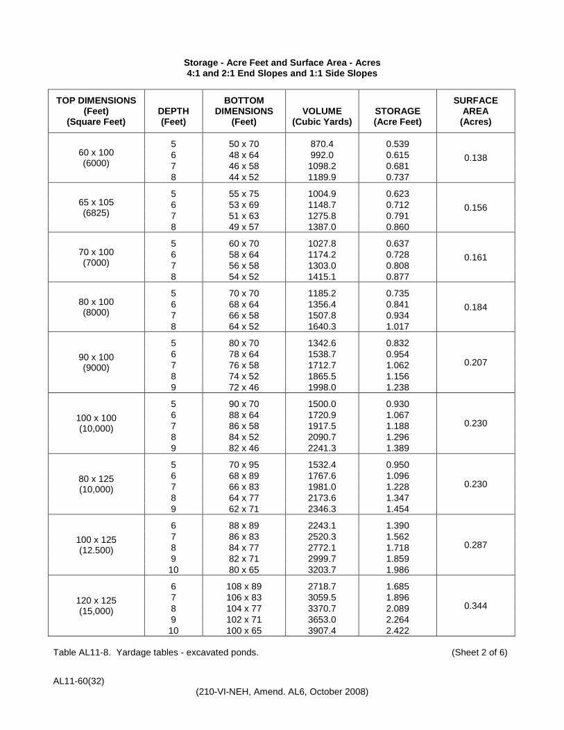
Table AL11-8. Yardage tables - excavated ponds. (Sheet 2 of 6)

AL11-60(33) (210-VI-NEH, Amend. AL6, October 2008)
Storage - Acre Feet and Surface Area - Acres 4:1 and 3:1 End Slopes and 2:1 Side Slopes
TOP DIMENSIONS (Feet)
(Square Feet) DEPTH (Feet)
BOTTOM DIMENSIONS
(Feet) VOLUME
(Cubic Yards) STORAGE (Acre Feet)
SURFACE AREA
(Acres)
40 x 40 (1600)
4 24 x 12 128.8 0.080 0.037 5 20 x 5 135.8 0.084
40 x 60 (2400)
4 24 x 32 223.6 0.139 0.055 5 20 x 25 246.9 0.153
6 16 x 18 261.3 0.162 7 12 x 11 268.0 0.166
40 x 75 (3000)
4 24 x 47 294.7 0.183
0.069 5 20 x 40 330.2 0.205 6 16 x 33 354.7 0.220 7 12 x 26 370.0 0.229 8 8 x 19 378.5 0.235
40 x 100 (4000)
4 24 x 72 413.2 0.256
0.092 5 20 x 65 469.1 0.291 6 16 x 58 510.2 0.316 7 12 x 51 538.6 0.334 8 8 x 44 556.2 0.345
50 x 60 (3000)
4 34 x 32 291.8 0.181 0.069 5 30 x 25 325.6 0.202
6 26 x 18 348.0 0.216 7 22 x 11 361.0 0.224
50 x 75 (3750)
5 30 x 40 436.7 0.271 0.086 6 26 x 33 474.7 0.294
7 22 x 26 501.0 0.311 8 18 x 19 517.7 0.321
50 x 90 (5400)
5 30 x 55 547.8 0.340 0.103 6 26 x 48 601.3 0.373
7 22 x 41 641.0 0.397 8 18 x 34 668.8 0.415
60 x 80 (4800)
5 40 x 45 589.5 0.365 0.110 6 36 x 38 648.0 0.402
7 32 x 31 691.5 0.429 8 28 x 24 722.2 0.448
60 x 90 (5400)
5 40 x 55 682.1 0.423 0.124 6 36 x 48 754.7 0.468 7 32 x 41 810.8 0.503 8 28 x 34 852.5 0.528
Table AL11-8. Yardage tables - excavated ponds. (Sheet 3 of 6)

AL11-60(34) (210-VI-NEH, Amend. AL6, October 2008)
Storage - Acre Feet and Surface Area - Acres 4:1 and 3:1 End Slopes and 2:1 Side Slopes
TOP DIMENSIONS (Feet)
(Square Feet) DEPTH (Feet)
BOTTOM DIMENSIONS
(Feet) VOLUME
(Cubic Yards) STORAGE (Acre Feet)
SURFACE AREA
(Acres)
60 x 100 (6000)
5 40 x 65 774.7 0.480 0.138 6 36 x 58 861.3 0.534
7 32 x 51 930.0 0.576 8 28 x 44 982.9 0.609
65 x 105 (6825)
5 45 x 70 902.0 0.559 0.157 6 41 x 63 1008.0 0.625
7 37 x 56 1094.0 0.678 8 33 x 49 1162.2 0.720
70 x 100 (7000)
5 50 x 65 927.5 0.575 0.161 6 46 x 58 1036.9 0.643
7 42 x 51 1125.8 0.698 8 38 x 44 1196.2 0.741
80 x 100 (8000)
5 60 x 65 1080.2 0.670 0.184 6 56 x 58 1212.4 0.751
7 52 x 51 1321.5 0.819 8 48 x 44 1409.6 0.874
90 x 100 (9000)
5 70 x 65 1233.0 0.764
0.207 6 66 x 58 1388.0 0.860 7 62 x 51 1517.3 0.940 8 58 x 44 1622.9 1.006 9 54 x 37 1707.0 1.058
100 x 100 (10,000)
5 80 x 65 1385.8 0.859
0.230 6 76 x 58 1563.6 0.969 7 72 x 51 1713.0 1.062 8 68 x 44 1836.2 1.138 9 64 x 37 1935.3 1.199
80 x 125 (10,000)
5 60 x 90 1404.3 0.870
0.230 6 56 x 83 1590.2 0.986 7 52 x 76 1749.3 1.084 8 48 x 69 1883.6 1.167 9 44 x 62 1995.3 1.237
100 x 125 (12.500)
6 76 x 83 2052.4 1.272
0.287 7 72 x 76 2270.4 1.407 8 68 x 69 2458.5 1.524 9 64 x 62 2618.7 1.623 10 60 x 55 2753.1 1.706
120 x 125 (15,000)
6 96 x 83 2514.7 1.559
0.344 7 92 x 76 2791.5 1.730 8 88 x 69 3033.3 1.880 9 84 x 62 3242.0 2.009 10 80 x 55 3419.8 2.120
Table AL11-8. Yardage tables - excavated ponds. (Sheet 4 of 6)

AL11-60(35) (210-VI-NEH, Amend. AL6, October 2008)
Storage - Acre Feet and Surface Area - Acres 4:1 and 3:1 End Slopes and 3:1 Side Slopes
TOP DIMENSIONS (Feet)
(Square Feet) DEPTH (Feet)
BOTTOM DIMENSIONS
(Feet) VOLUME
(Cubic Yards) STORAGE (Acre Feet)
SURFACE AREA
(Acres)
40 x 40 (1600)
4 16 x 12 116.1 0.072 0.037 5 10 x 5 120.4 0.075
40 x 60 (2400)
4 16 x 32 199.1 0.123 0.055 5 10 x 25 213.0 0.132
6 4 x 18 218.7 0.136
40 x 75 (3000)
4 16 x 47 261.3 0.162 0.069 5 10 x 40 282.4 0.175
6 4 x 33 292.0 0.181
40 x 100 (4000)
4 16 x 72 365.0 0.226 0.092 5 10 x 65 398.1 0.247
6 4 x 58 414.2 0.257
50 x 60 (3000)
4 26 x 32 267.3 0.166
0.069 5 20 x 25 291.7 0.181 6 14 x 18 305.3 0.189 7 8 x 11 311.4 0.193
50 x 75 (3750)
5 20 x 40 388.9 0.241 0.086 6 14 x 33 412.0 0.255
7 8 x 26 424.1 0.263
50 x 90 (4500)
5 20 x 55 486.1 0.301 0.103 6 14 x 48 518.7 0.321
7 8 x 41 536.9 0.333
60 x 80 (4800)
5 30 x 45 537.0 0.333 0.110 6 24 x 38 578.7 0.359
7 18 x 31 605.6 0.375 8 12 x 24 621.0 0.385
60 x 90 (5400)
5 30 x 55 620.4 0.385 0.124 6 24 x 48 672.0 0.417
7 18 x 41 706.7 0.438 8 12 x 34 727.7 0.451
60 x 100 (6000)
5 30 x 65 703.7 0.436 0.138 6 24 x 58 765.3 0.474
7 18 x 51 807.9 0.501 8 12 x 44 834.4 0.517
65 x 105 (6825)
5 35 x 70 826.4 0.512 0.157 6 29 x 63 905.3 0.561
7 23 x 56 962.3 0.597 8 17 x 49 1001.8 0.621
70 x 100 (7000)
5 40 x 65 856.5 0.531 0.161 6 34 x 58 940.9 0.583 7 28 x 51 1003.6 0.622 8 22 x 44 1047.7 0.649
Table AL11-8. Yardage tables - excavated ponds. (Sheet 5 of 6)

AL11-60(36) (210-VI-NEH, Amend. AL6, October 2008)
Storage - Acre Feet and Surface Area - Acres 4:1 and 3:1 End Slopes and 3:1 Side Slopes
TOP DIMENSIONS
(Feet) (Square Feet)
DEPTH (Feet)
BOTTOM DIMENSIONS
(Feet)
VOLUME (Cubic Yards)
STORAGE (Acre Feet)
SURFACE AREA
(Acres)
80 x 100 (8000)
5 50 x 65 1009.2 0.626 0.184 6 44 x 58 1116.4 0.692
7 38 x 51 1199.3 0.743 8 32 x 44 1261.0 0.782
90 x 100 (9000)
5 60 x 65 1162.0 0.720
0.207 6 54 x 58 1292.0 0.801 7 48 x 51 1395.1 0.865 8 42 x 44 1474.4 0.914 9 36 x 37 1533.0 0.950
100 x 100 (10,000)
5 70 x 65 1314.8 0.815
0.230 6 64 x 58 1467.6 0.910 7 58 x 51 1590.8 0.986 8 52 x 44 1687.7 1.046 9 46 x 37 1761.3 1.092
80 x 125 (10,000)
5 50 x 90 1310.2 0.812
0.230 6 44 x 83 1460.9 0.905 7 38 x 76 1581.7 0.980 8 32 x 69 1675.8 1.039 9 26 x 62 1746.3 1.082
100 x 125 (12.500)
6 64 x 83 1923.1 1.192
0.287 7 58 x 76 2102.9 1.303 8 52 x 69 2250.7 1.395 9 46 x 62 2369.7 1.469 10 40 x 55 2463.0 1.527
120 x 125 (15,000)
6 84 x 83 2385.3 1.478
0.344 7 78 x 76 2624.0 1.626 8 72 x 69 2825.5 1.751 9 66 x 62 2993.0 1.855 10 60 x 55 3129.6 1940
V = d (A1 = 4Am + A2)
A1 = Top Area - Square Feet
162 V = Volume - Cubic Yards A2 = Bottom Area - Square Feet d = Depth - Feet Am = Area of Cross-section halfway between A1 and A1 - Sq. Ft. NOTE: The following formula may be used to compute quantities for excavated ponds not included in this table: V = 1/3 (A1 + A2 + A1 x A2 ) d/27 VOLUME OF EXCAVATION FOR INCREMENTS OF DEPTH OTHER THAN SHOWN MAY BE
OBTAINED BY STRAIGHT LINE EXTRAPOLATION. VOLUMES FOUND BY EXTRAPOLATION ARE WITHIN 0.5% OF TRUE COMPUTED VALUES. Table 11-8. Yardage tables - excavated ponds. (Sheet 6 of 6)

4:1 and 2:1 End Slopes and 1:1 Side Slopes
TOP DIM. FT. (sq. ft.) “ac.”
DEPTH (ft.)
BOTTOM DIM. (ft.)
VOLUME (cu. yd.)
TOTAL WATER NEEDS FOR CATTLE (ac.-ft.)
60 days 90 days 120 days 180 days 270 days
40 x 40 (1600) “0.037”
4 32 x 16 151.7 0.050 0.028 0.006 - - - - - - - - - - - - - - 5 30 x 10 166.7 0.059 0.037 0.016 - - - - - - - - - - - - - - 6 28 x 4 174.2 0.064 0.042 0.020 - - - - - - - - - - - - - -
40 x 60 (2400) “0.055”
4 32 x 36 258.4 0.094 0.061 0.029 - - - - - - - - - - - - - - 5 30 x 30 296.3 0.118 0.085 0.052 - - - - - - - - - - - - - - 6 28 x 24 325.3 0.136 0.103 0.070 0.004 - - - - - - - 7 26 x 18 346.4 0.149 0.116 0.083 0.017 - - - - - - -
40 x 75 (3000) “0.069”
4 32 x 51 338.4 0.127 0.086 0.045 - - - - - - - - - - - - - - 5 30 x 45 393.5 0.162 0.121 0.079 - - - - - - - - - - - - - - 6 28 x 39 438.7 0.190 0.149 0.107 0.025 - - - - - - - 7 26 x 33 474.7 0.212 0.171 0.130 0.047 - - - - - - - 8 24 x 27 502.5 0.229 0.188 0.147 0.065 - - - - - - -
40 x 100 (4000) “0.092”
4 32 x 76 471.7 0.183 0.128 0.073 - - - - - - - - - - - - - - 5 30 x 70 555.5 0.235 0.180 0.125 0.015 - - - - - - - 6 28 x 64 627.6 0.279 0.224 0.170 0.060 - - - - - - - 7 26 x 58 688.6 0.317 0.262 0.207 0.098 - - - - - - - 8 24 x 52 739.6 0.349 0.294 0.239 0.129 - - - - - - -
50 x 60 (3000) “0.069”
4 42 x 36 329.5 0.122 0.081 0.040 - - - - - - - - - - - - - - 5 40 x 30 379.6 0.153 0.112 0.071 - - - - - - - - - - - - - - 6 38 x 24 418.7 0.177 0.136 0.095 0.013 - - - - - - - 7 36 x 18 447.5 0.195 0.154 0.113 0.031 - - - - - - -
50 x 75 (3750) “0.086”
5 40 x 45 504.6 0.210 0.159 0.107 0.004 - - - - - - - 6 38 x 39 565.3 0.248 0.196 0.145 0.042 - - - - - - - 7 36 x 33 614.7 0.278 0.227 0.175 0.073 - - - - - - - 8 34 x 27 653.6 0.302 0.251 0.199 0.097 - - - - - - -
Table AL11-9. Excavated pond - alternative design table. (Sheet 1 of 9)
AL11-60(37) (210-VI-N
EH, Am
end. AL4, N
ovember 2006)

4:1 and 2:1 End Slopes and 1:1 Side Slopes
TOP DIM. FT. (sq. ft.) “ac.”
DEPTH (ft.)
BOTTOM DIM. (ft.)
VOLUME (cu. yd.)
TOTAL WATER NEEDS FOR CATTLE (ac.-ft.)
60 days 90 days 120 days 180 days 270 days
50 x 90 (4500) “0.103”
5 40 x 60 629.6 0.267 0.205 0.143 0.020 - - - - - - - 6 38 x 54 712.0 0.318 0.256 0.195 0.071 - - - - - - - 7 36 x 48 781.9 0.361 0.300 0.238 0.114 8 34 x 42 840.3 0.397 0.336 0.274 0.151 - - - - - - -
60 x 80 (4800) “0.110”
5 50 x 50 666.7 0.282 0.216 0.150 0.018 - - - - - - - 6 48 x 44 752.0 0.334 0.269 0.203 0.071 - - - - - - - 7 46 x 38 823.4 0.379 0.313 0.247 0.116 - - - - - - - 8 44 x 32 881.8 0.415 0.349 0.283 0.152 - - - - - - -
60 x 90 (5400) “0.124”
5 50 x 60 768.5 0.328 0.254 0.180 0.032 - - - - - - - 6 48 x 54 872.0 0.392 0.318 0.244 0.096 - - - - - - - 7 46 x 48 960.8 0.447 0.373 0.299 0.151 - - - - - - - 8 44 x 42 1035.9 0.494 0.420 0.346 0.198 - - - - - - -
60 x 100 (6000) “0.138”
5 50 x 70 870.4 0.375 0.293 0.210 0.046 - - - - - - - 6 48 x 64 992.0 0.450 0.368 0.286 0.121 - - - - - - - 7 46 x 58 1098.2 0.516 0.434 0.352 0.187 - - - - - - - 8 44 x 52 1189.9 0.573 0.491 0.409 0.244 - - - - - - -
65 x 105 (6825) “0.156”
5 55 x 75 1004.6 0.436 0.342 0.248 0.061 - - - - - - - 6 53 x 69 1148.7 0.525 0.431 0.338 0.151 - - - - - - - 7 51 x 63 1275.8 0.604 0.510 0.417 0.229 - - - - - - - 8 49 x 57 1387.0 0.673 0.579 0.485 0.298 0.018
70 x 100 (7000) “0.161”
5 60 x 70 1027.8 0.445 0.349 0.253 0.061 - - - - - - - 6 58 x 64 1174.2 0.536 0.440 0.344 0.152 - - - - - - - 7 56 x 58 1303.0 0.616 0.520 0.424 0.232 - - - - - - - 8 54 x 52 1415.1 0.685 0.589 0.493 0.301 0.013
Table AL11-9. Excavated pond - alternative design table. (Sheet 2 of 9
AL11-60(38) (210-VI-N
EH, Am
end. AL4, N
ovember 2006)

4:1 and 2:1 End Slopes and 1:1 Side Slopes
TOP DIM. FT. (sq. ft.) “ac.”
DEPTH (ft.)
BOTTOM DIM. (ft.)
VOLUME (cu. yd.)
TOTAL WATER NEEDS FOR CATTLE (ac.-ft.)
60 days 90 days 120 days 180 days 270 days
80 x 100 (8000) “0.184”
5 70 x 70 1185.2 0.515 0.406 0.296 0.077 - - - - - - - 6 68 x 64 1356.4 0.621 0.512 0.402 0.183 - - - - - - - 7 66 x 58 1507.8 0.715 0.606 0.496 0.277 - - - - - - - 8 64 x 52 1640.3 0.797 0.688 0.578 0.359 0.030
90 x 100 (9000) “0.207”
5 80 x 70 1342.6 0.585 0.462 0.339 0.092 - - - - - - - 6 78 x 64 1538.7 0.707 0.584 0.460 0.213 - - - - - - - 7 76 x 58 1712.7 0.815 0.691 0.568 0.321 - - - - - - - 8 74 x 52 1865.5 0.910 0.786 0.663 0.416 0.046 9 72 x 46 1998.0 0.992 0.868 0.745 0.498 0.128
100 x 100 (10,000) “0.230”
5 90 x 70 1500.0 0.656 0.518 0.381 0.107 - - - - - - - 6 88 x 64 1720.9 0.792 0.655 0.518 0.244 - - - - - - - 7 86 x 58 1917.5 0.914 0.777 0.640 0.366 - - - - - - - 8 84 x 52 2090.7 1.022 0.885 0.747 0.473 0.062 9 82 x 46 2241.3 1.115 0.978 0.841 0.567 0.155
80 x 125 (10,000) “0.230”
5 70 x 95 1532.4 0.676 0.539 0.401 0.127 - - - - - - - 6 68 x 89 1767.6 0.821 0.684 0.547 0.273 - - - - - - - 7 66 x 83 1981.0 0.954 0.817 0.679 0.405 - - - - - - - 8 64 x 77 2173.6 1.073 0.936 0.799 0.525 0.113 9 62 x 71 2346.3 1.180 1.043 0.906 0.632 0.220
100 x 125 (12,500) “0.287”
6 88 x 89 2243.1 1.048 0.876 0.705 0.362 - - - - - - - 7 86 x 83 2520.3 1.219 1.048 0.877 0.534 0.020 8 84 x 77 2772.1 1.376 1.204 1.033 0.690 0.176 9 82 x 71 2999.7 1.517 1.345 1.174 0.831 0.317 10 80 x 65 3203.7 1.643 1.472 1.300 0.957 0.443
120 x 125 (15,000) “0.344”
6 108 x 89 2718.7 1.274 1.068 0.863 0.451 - - - - - - - 7 106 x 83 3059.5 1.485 1.279 1.074 0.662 0.046 8 104 x 77 3370.7 1.678 1.472 1.267 0.855 0.238 9 102 x 71 3653.0 1.853 1.647 1.442 1.030 0.413 10 100 x 65 3907.4 2.011 1.805 1.599 1.188 0.517
Table AL11-9. Excavated pond - alternative design table. (Sheet 3 of 9)
AL11-60(39) (210-VI-N
EH, Am
end. AL4, N
ovember 2006)

4:1 and 3:1 End Slopes and 2:1 Side Slopes
TOP DIM. FT. (sq. ft.) “ac.”
DEPTH (ft.)
BOTTOM DIM. (ft.)
VOLUME (cu. yd.)
TOTAL WATER NEEDS FOR CATTLE (ac.-ft.)
60 days 90 days 120 days 180 days 270 days
40 x 40 (1600) “0.037”
4 24 x 12 128.8 0.036 0.014 - - - - - - - - - - - - - - - - - - - - - 5 20 x 5 135.8 0.040 0.018 - - - - - - - - - - - - - - - - - - - - -
40 x 60 (2400) “0.055”
4 24 x 32 223.6 0.073 0.040 0.007 - - - - - - - - - - - - - - 5 20 x 25 246.9 0.087 0.054 0.021 - - - - - - - - - - - - - - 6 16 x 18 261.3 0.096 0.063 0.030 - - - - - - - - - - - - - - 7 12 x 11 268.9 0.101 0.068 0.035 - - - - - - - - - - - - - -
40 x 75 (3000) “0.069”
4 24 x 47 294.7 0.100 0.059 0.018 - - - - - - - - - - - - - - 5 20 x 40 330.2 0.122 0.081 0.040 - - - - - - - - - - - - - - 6 16 x 33 354.7 0.138 0.096 0.055 - - - - - - - - - - - - - - 7 12 x 26 370.0 0.147 0.106 0.065 - - - - - - - - - - - - - - 8 8 x 19 378.5 0.152 0.111 0.070 - - - - - - - - - - - - - -
40 x 100 (4000) “0.092”
4 24 x 72 413.2 0.146 0.092 0.037 - - - - - - - - - - - - - - 5 20 x 65 469.1 0.181 0.126 0.071 - - - - - - - - - - - - - - 6 16 x 58 510.2 0.207 0.152 0.097 - - - - - - - - - - - - - - 7 12 x 51 538.6 0.224 0.169 0.114 0.005 - - - - - - - 8 8 x 44 556.2 0.235 0.180 0.125 0.016 - - - - - - -
50 x 60 (3000) “0.069”
4 34 x 32 291.8 0.099 0.057 0.016 - - - - - - - - - - - - - - 5 30 x 25 325.6 0.120 0.078 0.037 - - - - - - - - - - - - - - 6 26 x 18 348.0 0.133 0.092 0.051 - - - - - - - - - - - - - - 7 22 x 11 361.0 0.141 0.100 0.059 - - - - - - - - - - - - - -
50 x 75 (3750) “0.086”
5 30 x 40 436.7 0.168 0.116 0.065 - - - - - - - - - - - - - - 6 26 x 33 474.7 0.191 0.140 0.089 - - - - - - - - - - - - - - 7 22 x 26 501.0 0.208 0.156 0.105 0.002 - - - - - - - 8 18 x 19 517.7 0.218 0.167 0.115 0.012 - - - - - - -
Table AL11-9. Excavated pond - alternative design table. (Sheet 4 of 9)
AL11-60(40) (210-VI-N
EH, Am
end. AL4, N
ovember 2006)

4:1 and 3:1 End Slopes and 2:1 Side Slopes
TOP DIM. FT. (sq. ft.) “ac.”
DEPTH (ft.)
BOTTOM DIM. (ft.)
VOLUME (cu. yd.)
TOTAL WATER NEEDS FOR CATTLE (ac.-ft.)
60 days 90 days 120 days 180 days 270 days
50 x 90 (4500) “0.103”
5 30 x 55 547.8 0.216 0.154 0.093 - - - - - - - - - - - - - - 6 26 x 48 601.3 0.249 0.188 0.126 0.003 - - - - - - - 7 22 x 41 641.0 0.274 0.212 0.151 0.027 8 18 x 34 668.8 0.291 0.229 0.168 0.044 - - - - - - -
60 x 80 (4800) “0.110”
5 40 x 45 589.5 0.234 0.168 0.102 - - - - - - - - - - - - - - 6 36 x 38 648.0 0.270 0.204 0.138 0.007 - - - - - - - 7 32 x 31 691.5 0.297 0.231 0.165 0.034 - - - - - - - 8 28 x 24 722.2 0.316 0.250 0.184 0.053 - - - - - - -
60 x 90 (5400) “0.124”
5 40 x 55 682.1 0.275 0.201 0.127 - - - - - - - - - - - - - - 6 36 x 48 754.7 0.320 0.246 0.172 0.024 - - - - - - - 7 32 x 41 810.8 0.354 0.280 0.206 0.058 - - - - - - - 8 28 x 34 852.5 0.380 0.306 0.232 0.084 - - - - - - -
60 x 100 (6000) “0.138”
5 40 x 65 774.7 0.316 0.233 0.151 - - - - - - - - - - - - - - 6 36 x 58 861.3 0.369 0.287 0.205 0.040 - - - - - - - 7 32 x 51 930.0 0.412 0.330 0.247 0.083 - - - - - - - 8 28 x 44 982.9 0.445 0.362 0.280 0.116 - - - - - - -
65 x 105 (6825) “0.156”
5 45 x 70 902.0 0.372 0.278 0.185 - - - - - - - - - - - - - - 6 41 x 63 1008.0 0.438 0.344 0.251 0.063 - - - - - - - 7 37 x 56 1094.0 0.491 0.397 0.304 0.117 - - - - - - - 8 33 x 49 1162.2 0.533 0.440 0.346 0.159 - - - - - - -
70 x 100 (7000) “0.161”
5 50 x 65 927.5 0.383 0.287 0.191 - - - - - - - - - - - - - - 6 56 x 58 1036.9 0.451 0.355 0.259 0.067 - - - - - - - 7 52 x 51 1125.8 0.506 0.410 0.314 0.122 - - - - - - - 8 48 x 44 1196.2 0.550 0.454 0.358 0.166 - - - - - - -
Table AL11-9. Excavated pond - alternative design table. (Sheet 5 of 9)
AL11-60(41) (210-VI-N
EH, Am
end. AL4, N
ovember 2006)

4:1 and 3:1 End Slopes and 2:1 Side Slopes
TOP DIM. FT. (sq. ft.) “ac.”
DEPTH (ft.)
BOTTOM DIM. (ft.)
VOLUME (cu. yd.)
TOTAL WATER NEEDS FOR CATTLE (ac.-ft.)
60 days 90 days 120 days 180 days 270 days
80 x 100 (8000) “0.184”
5 60 x 65 1080.2 0.450 0.341 0.231 0.011 - - - - - - - 6 56 x 58 1212.4 0.532 0.422 0.313 0.093 - - - - - - - 7 52 x 51 1321.5 0.600 0.490 0.380 0.161 - - - - - - - 8 48 x 44 1409.6 0.654 0.545 0.435 0.216 - - - - - - -
90 x 100 (9000) “0.207”
5 70 x 65 1233.0 0.517 0.394 0.271 0.024 - - - - - - - 6 66 x 58 1388.0 0.614 0.490 0.367 0.120 - - - - - - - 7 62 x 51 1517.3 0.694 0.570 0.447 0.200 - - - - - - - 8 58 x 44 1622.9 0.759 0.636 0.512 0.266 - - - - - - - 9 54 x 37 1707.0 0.811 0.688 0.564 0.318 - - - - - - -
100 x 100 (10,000) “0.230”
5 80 x 65 1385.8 0.585 0.448 0.311 0.036 - - - - - - - 6 76 x 58 1563.6 0.695 0.558 0.421 0.147 - - - - - - - 7 72 x 51 1713.0 0.788 0.650 0.513 0.239 - - - - - - - 8 68 x 44 1836.2 0.864 0.727 0.590 0.316 - - - - - - - 9 64 x 37 1935.3 0.925 0.788 0.651 0.377 - - - - - - -
80 x 125 (10,000) “0.230”
5 60 x 90 1404.3 0.596 0.459 0.322 0.048 - - - - - - - 6 56 x 83 1590.2 0.711 0.574 0.437 0.163 - - - - - - - 7 52 x 76 1749.3 0.810 0.673 0.536 0.262 - - - - - - - 8 48 x 69 1883.7 0.893 0.756 0.619 0.345 - - - - - - - 9 44 x 62 1995.3 0.963 0.825 0.688 0.414 0.003
100 x 125 (12,500) “0.287”
6 76 x 83 2052.4 0.929 0.758 0.587 0.244 - - - - - - - 7 72 x 76 2270.4 1.065 0.893 0.722 0.379 - - - - - - - 8 68 x 69 2458.5 1.181 1.010 0.838 0.496 - - - - - - - 9 64 x 62 2618.7 1.280 1.109 0.938 0.595 0.081 10 60 x 55 2753.1 1.364 1.192 1.021 0.678 0.164
120 x 125 (15,000) “0.344”
6 96 x 83 2514.7 1.147 0.942 0.736 0.325 - - - - - - - 7 92 x 76 2791.5 1.319 1.113 0.908 0.496 - - - - - - - 8 88 x 69 3033.3 1.469 1.263 1.058 0.646 0.029 9 84 x 62 3242.0 1.598 1.393 1.187 0.776 0.159 10 80 x 55 3419.8 1.708 1.503 1.297 0.886 0.269
Table AL11-9. Excavated pond - alternative design table. (Sheet 6 of 9)
AL11-60(42) (210-VI-N
EH, Am
end. AL4, N
ovember 2006)

4:1 and 3:1 End Slopes and 3:1 Side Slopes
TOP DIM. FT. (sq. ft.) “ac.”
DEPTH (ft.)
BOTTOM DIM. (ft.)
VOLUME (cu. yd.)
TOTAL WATER NEEDS FOR CATTLE (ac.-ft.)
60 days 90 days 120 days 180 days 270 days
40 x 40 (1600) “0.037”
4 16 x 12 116.1 0.028 0.006 - - - - - - - - - - - - - - - - - - - - - 5 10 x 5 120.4 0.031 0.009 - - - - - - - - - - - - - - - - - - - - -
40 x 60 (2400) “0.055”
4 16 x 32 199.1 0.058 0.025 - - - - - - - - - - - - - - - - - - - - - 5 10 x 25 213.0 0.066 0.033 - - - - - - - - - - - - - - - - - - - - - 6 4 x 18 218.7 0.070 0.037 0.004 - - - - - - - - - - - - - -
40 x 75 (3000) “0.069”
4 16 x 47 261.3 0.080 0.039 - - - - - - - - - - - - - - - - - - - - - 5 10 x 40 282.4 0.093 0.052 0.011 - - - - - - - - - - - - - - 6 4 x 33 292.0 0.099 0.058 0.016 - - - - - - - - - - - - - -
40 x 100 (4000) “0.092”
4 16 x 72 365.0 0.117 0.062 0.007 - - - - - - - - - - - - - - 5 10 x 65 398.1 0.137 0.082 0.027 - - - - - - - - - - - - - - 6 4 x 58 414.2 0.147 0.092 0.037 - - - - - - - - - - - - - -
50 x 60 (3000) “0.069”
4 26 x 32 267.3 0.083 0.042 0.001 - - - - - - - - - - - - - - 5 20 x 25 291.7 0.099 0.057 0.016 - - - - - - - - - - - - - - 6 14 x 18 305.3 0.107 0.066 0.025 - - - - - - - - - - - - - - 7 8 x 11 311.4 0.111 0.070 0.028 - - - - - - - - - - - - - -
50 x 75 (3750) “0.086”
5 20 x 40 388.9 0.138 0.087 0.035 - - - - - - - - - - - - - - 6 14 x 33 412.0 0.153 0.101 0.050 - - - - - - - - - - - - - - 8 x 26 424.1 0.160 0.109 0.057 - - - - - - - - - - - - - -
50 x 90 (4500) “0.103”
5 20 x 55 486.1 0.178 0.116 0.055 - - - - - - - - - - - - - - 6 14 x 48 518.7 0.198 0.136 0.075 - - - - - - - - - - - - - - 7 8 x 41 536.9 0.209 0.148 0.086 - - - - - - - - - - - - - -
60 x 80 (4800) “0.110”
5 30 x 45 537.0 0.201 0.135 0.070 - - - - - - - - - - - - - - 6 24 x 38 578.7 0.227 0.161 0.095 - - - - - - - - - - - - - - 7 18 x 31 605.6 0.244 0.178 0.112 - - - - - - - - - - - - - - 8 12 x 24 621.0 0.253 0.188 0.122 - - - - - - - - - - - - - -
Table AL11-9. Excavated pond - alternative design table. (Sheet 7 of 9)
AL11-60(43) (210-VI-N
EH, Am
end. AL4, N
ovember 2006)

4:1 and 3:1 End Slopes and 3:1 Side Slopes
TOP DIM. FT. (sq. ft.) “ac.”
DEPTH (ft.)
BOTTOM DIM. (ft.)
VOLUME (cu. yd.)
TOTAL WATER NEEDS FOR CATTLE (ac.-ft.)
60 days 90 days 120 days 180 days 270 days
60 x 90 (5400) “0.124”
5 30 x 55 620.4 0.236 0.162 0.088 - - - - - - - - - - - - - - 6 24 x 48 672.0 0.268 0.194 0.120 - - - - - - - - - - - - - - 7 18 x 41 706.7 0.290 0.216 0.142 - - - - - - - - - - - - - - 8 12 x 34 727.7 0.303 0.229 0.155 0.007 - - - - - - -
60 x 100 (6000) “0.138”
5 30 x 65 703.7 0.272 0.189 0.107 - - - - - - - - - - - - - - 6 24 x 58 765.3 0.310 0.228 0.145 - - - - - - - - - - - - - - 7 18 x 51 807.9 0.336 0.254 0.172 0.007 - - - - - - - 8 12 x 44 834.4 0.353 0.270 0.188 0.024 - - - - - - -
65 x 105 (6825) “0.157”
5 35 x 70 826.4 0.325 0.232 0.138 - - - - - - - - - - - - - - 6 29 x 63 905.3 0.374 0.280 0.187 - - - - - - - - - - - - - - 7 23 x 56 962.8 0.410 0.316 0.222 0.035 - - - - - - - 8 17 x 49 1001.8 0.434 0.340 0.247 0.059 - - - - - - -
70 x 100 (7000) “0.161”
5 40 x 65 856.5 0.339 0.243 0.147 - - - - - - - - - - - - - - 6 34 x 58 940.9 0.391 0.295 0.199 0.007 - - - - - - - 7 28 x 51 1003.6 0.430 0.334 0.238 0.046 - - - - - - - 8 22 x 44 1047.7 0.457 0.361 0.266 0.074 - - - - - - -
80 x 100 (8000) “0.184”
5 50 x 65 1009.2 0.406 0.297 0.187 - - - - - - - - - - - - - - 6 44 x 58 1116.4 0.473 0.363 0.253 0.034 - - - - - - - 7 38 x 51 1199.3 0.524 0.414 0.305 0.085 - - - - - - - 8 32 x 44 1261.0 0.562 0.453 0.343 0.124 - - - - - - -
90 x 100 (9000) “0.207”
5 60 x 65 1162.0 0.473 0.350 0.227 - - - - - - - - - - - - - - 6 54 x 58 1292.0 0.554 0.431 0.307 0.060 - - - - - - - 7 48 x 51 1395.1 0.618 0.495 0.371 0.124 - - - - - - - 8 42 x 44 1474.4 0.667 0.544 0.420 0.174 - - - - - - - 9 36 x 37 1533.0 0.703 0.580 0.457 0.210 - - - - - - -
Table AL11-9. Excavated pond - alternative design table. (Sheet 8 of 9)
AL11-60(44) (210-VI-N
EH, Am
end. AL4, N
ovember 2006)
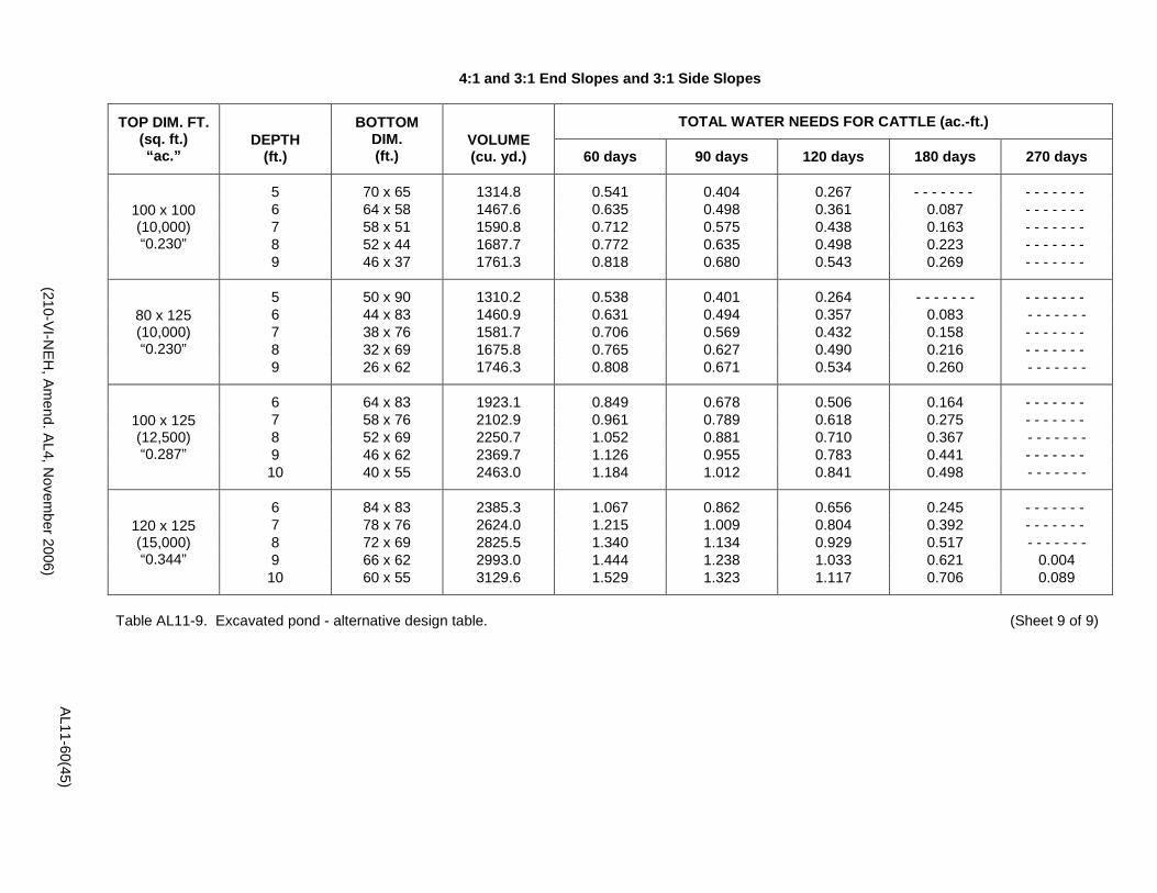
4:1 and 3:1 End Slopes and 3:1 Side Slopes
TOP DIM. FT. (sq. ft.) “ac.”
DEPTH (ft.)
BOTTOM DIM. (ft.)
VOLUME (cu. yd.)
TOTAL WATER NEEDS FOR CATTLE (ac.-ft.)
60 days 90 days 120 days 180 days 270 days
100 x 100 (10,000) “0.230”
5 70 x 65 1314.8 0.541 0.404 0.267 - - - - - - - - - - - - - - 6 64 x 58 1467.6 0.635 0.498 0.361 0.087 - - - - - - - 7 58 x 51 1590.8 0.712 0.575 0.438 0.163 - - - - - - - 8 52 x 44 1687.7 0.772 0.635 0.498 0.223 - - - - - - - 9 46 x 37 1761.3 0.818 0.680 0.543 0.269 - - - - - - -
80 x 125 (10,000) “0.230”
5 50 x 90 1310.2 0.538 0.401 0.264 - - - - - - - - - - - - - - 6 44 x 83 1460.9 0.631 0.494 0.357 0.083 - - - - - - - 7 38 x 76 1581.7 0.706 0.569 0.432 0.158 - - - - - - - 8 32 x 69 1675.8 0.765 0.627 0.490 0.216 - - - - - - - 9 26 x 62 1746.3 0.808 0.671 0.534 0.260 - - - - - - -
100 x 125 (12,500) “0.287”
6 64 x 83 1923.1 0.849 0.678 0.506 0.164 - - - - - - - 7 58 x 76 2102.9 0.961 0.789 0.618 0.275 - - - - - - - 8 52 x 69 2250.7 1.052 0.881 0.710 0.367 - - - - - - - 9 46 x 62 2369.7 1.126 0.955 0.783 0.441 - - - - - - - 10 40 x 55 2463.0 1.184 1.012 0.841 0.498 - - - - - - -
120 x 125 (15,000) “0.344”
6 84 x 83 2385.3 1.067 0.862 0.656 0.245 - - - - - - - 7 78 x 76 2624.0 1.215 1.009 0.804 0.392 - - - - - - - 8 72 x 69 2825.5 1.340 1.134 0.929 0.517 - - - - - - - 9 66 x 62 2993.0 1.444 1.238 1.033 0.621 0.004 10 60 x 55 3129.6 1.529 1.323 1.117 0.706 0.089
Table AL11-9. Excavated pond - alternative design table. (Sheet 9 of 9)
AL11-60(45) (210-VI-N
EH, Am
end. AL4, N
ovember 2006)