Embed Size (px)
Citation preview
Operator’s Manual
First Edition
First Printing
Part No. 114426
with
Maintenance
Information
AL8000 HT
Operator's Manual
AL8000 HT Part No. 114426
First Edition • First Printing
Copyright © 2007 by Terex
Terex Light Construction Division590 Huey RoadRock Hill, SC 29730
First Edition: First Printing, August 2007
Printed on recycled paper
Printed in U.S.A.
Important
Read, understand and obey these safety rules andoperating instructions before operating this machine.Only trained and authorized personnel shall bepermitted to operate this machine. This manualshould be considered a permanent part of yourmachine and should remain with the machine at alltimes. If you have any questions, call Terex.
Contents
PageIntroduction ................................................................ 1Symbol and Hazard Pictorials Definitions ................... 3General Safety ........................................................... 4Work Area Safety ....................................................... 9Legend ...................................................................... 12Controls .................................................................... 13Inspections ............................................................... 17Operating Instructions ............................................... 26Transport and Lifting Instructions .............................. 30Maintenance ............................................................. 32Specifications ........................................................... 34Reporting Safety Defects .......................................... 35
Contact us:
Internet: www.genielift.come-mail: [email protected]
Part No. 114426 AL8000 HT 1
Operator's ManualFirst Edition • First Printing
Introduction
Danger
Failure to obey the instructions andsafety rules in this manual willresult in death or serious injury.
Do Not Operate Unless:
You learn and practice the principles of safemachine operation contained in this operator'smanual.
1 Avoid hazardous situations.
Know and understand the safety rules beforegoing on to the next section.
2 Always perform a pre-operation inspection.
3 Always perform function tests prior to use.
4 Inspect the workplace.
5 Only use the machine as it was intended.
You read, understand and obey themanufacturer's instructions and safety rules—safety and operator's manuals and machinedecals.
You read, understand and obey employer'ssafety rules and worksite regulations.
You read, understand and obey all applicablegovernmental regulations.
You are properly trained to safely operate themachine.
Owners, Users and Operators:
Terex appreciates your choice of our machine foryour application. Our number one priority is usersafety, which is best achieved by our joint efforts.We feel that you make a major contribution tosafety if you, as the equipment users andoperators:
1 Comply with employer, job site andgovernmental rules.
2 Read, understand and follow the instructionsin this and other manuals supplied with thismachine.
3 Use good safe work practices in acommonsense way.
4 Only have trained/certified operators, directedby informed and knowledgeable supervision,running the machine.
If there is anything in this manual that is not clearor which you believe should be added, pleasecontact us.
Internet: www.genielift.come-mail: [email protected]
Operator's Manual First Edition • First Printing
2 AL8000 HT Part No. 114426
Intended Use
This machine is intended to be used only to providelighting and electrical power to a work site.
Introduction
Safety Sign Maintenance
Replace any missing or damaged safety signs.Keep operator safety in mind at all times. Use mildsoap and water to clean safety signs. Do not usesolvent-based cleaners because they may damagethe safety sign material.
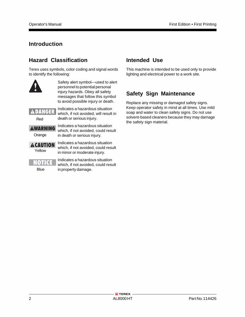
Hazard Classification
Terex uses symbols, color coding and signal wordsto identify the following:
Safety alert symbol—used to alertpersonnel to potential personalinjury hazards. Obey all safetymessages that follow this symbolto avoid possible injury or death.
Indicates a hazardous situationwhich, if not avoided, will result indeath or serious injury.
Indicates a hazardous situationwhich, if not avoided, could resultin death or serious injury.
Indicates a hazardous situationwhich, if not avoided, could resultin minor or moderate injury.
Indicates a hazardous situationwhich, if not avoided, could resultin property damage.
Red
Orange
Yellow
Blue
Part No. 114426 AL8000 HT 3
Operator's ManualFirst Edition • First Printing
Crushing Hazard
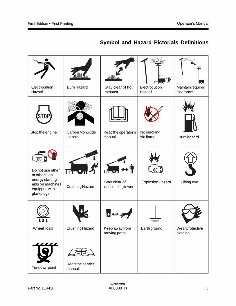
Symbol and Hazard Pictorials Definitions
ElectrocutionHazard
Maintain requiredclearance.
Read the operator’smanual.
Keep away frommoving parts.
Wheel load
No smoking.No flame. Burn hazard
Do not use etheror other highenergy startingaids on machinesequipped withglow plugs
Explosion Hazard Lifting eye
ElectrocutionHazard
STOP
Stop the engine
Crushing HazardStay clear ofdescending tower
Carbon MonoxideHazard
Burn Hazard Stay clear of hotexhaust
Earth ground Wear protectiveclothing
Tie-down pointRead the servicemanual.
Operator's Manual First Edition • First Printing
4 AL8000 HT Part No. 114426
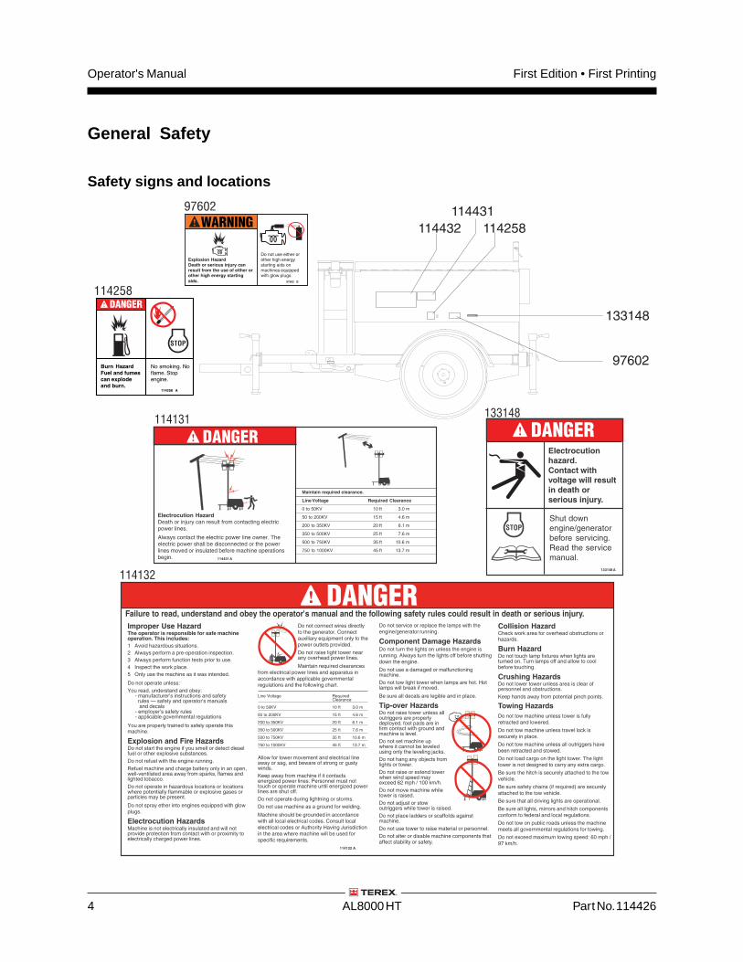
General Safety
Safety signs and locations
114132
114432
114431
97602
133148
114258
DANGER
114258
114131
WARNING
97602
DANGER
DANGER
133148
DANGER
Part No. 114426 AL8000 HT 5
Operator's ManualFirst Edition • First Printing
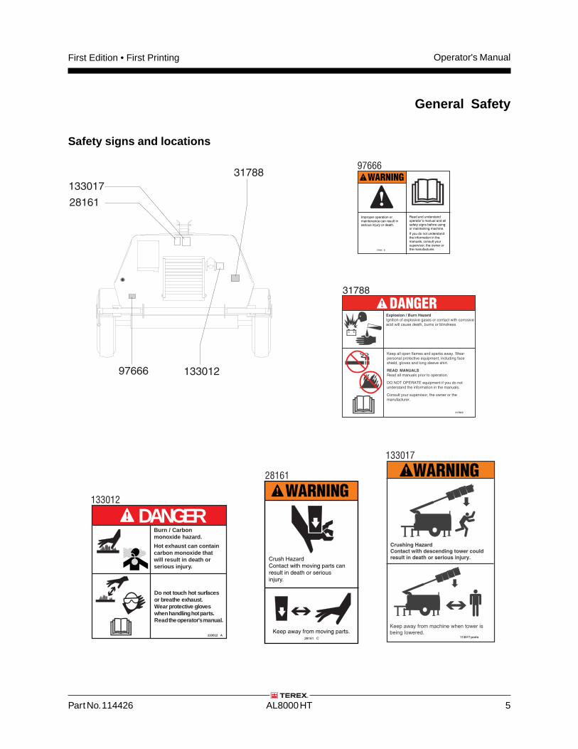
Safety signs and locations
General Safety
28161
133017
28161 C
Crush HazardContact with moving parts canresult in death or seriousinjury.
WARNING
Keep away from moving parts.
WARNING
133012
28161
13301297666
133017
97666
97666 B
Read and understandoperator's manual and allsafety signs before usingor maintaining machine.
If you do not understandthe information in themanuals, consult yoursupervisor, the owner orthe manufacturer.
WARNING
Improper operation ormaintenance can result inserious injury or death.
31788
31788
DANGER
Burn / Carbonmonoxide hazard.
Hot exhaust can containcarbon monoxide thatwill result in death orserious injury.
133012 A
DANGER
Do not touch hot surfacesor breathe exhaust.Wear protective gloveswhen handling hot parts.Read the operator's manual.
Operator's Manual First Edition • First Printing
6 AL8000 HT Part No. 114426
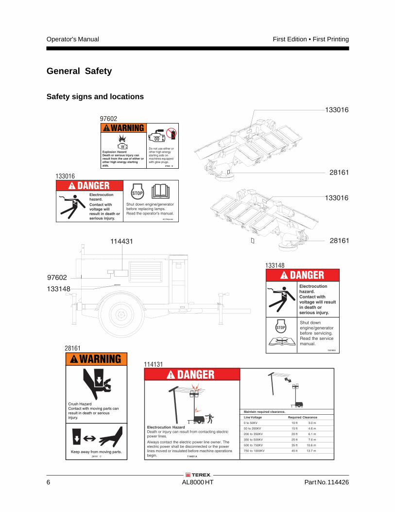
General Safety
Safety signs and locations
114131
28161
114431
133148
DANGER
28161
28161
133016
133016
133016
133148
DANGER
28161 C
Crush HazardContact with moving parts canresult in death or seriousinjury.
WARNING
Keep away from moving parts.
97602
WARNING
97602
DANGER
Part No. 114426 AL8000 HT 7
Operator's ManualFirst Edition • First Printing
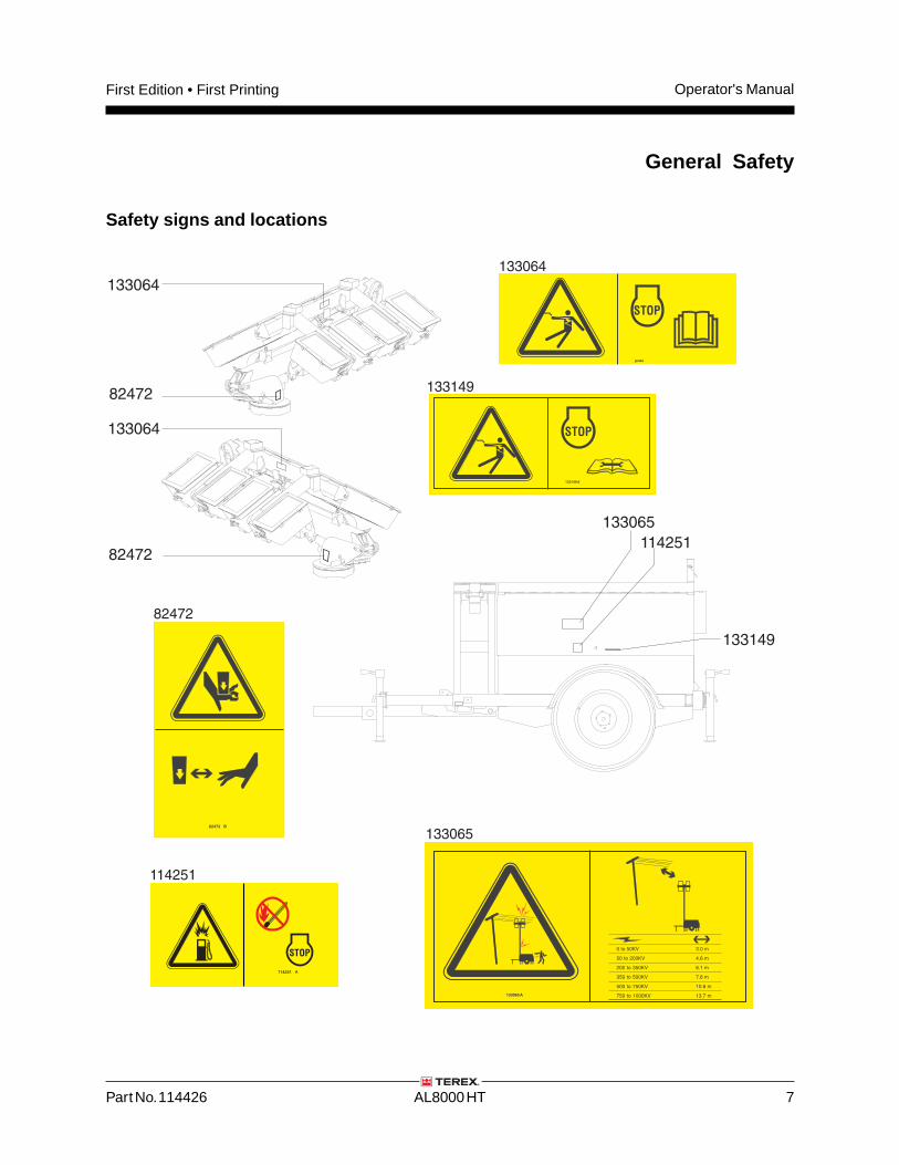
General Safety
Safety signs and locations
114251
133065
114251 A
133065
114251
82472
82472
133064
133064133064
133149
82472
133149
Operator's Manual First Edition • First Printing
8 AL8000 HT Part No. 114426
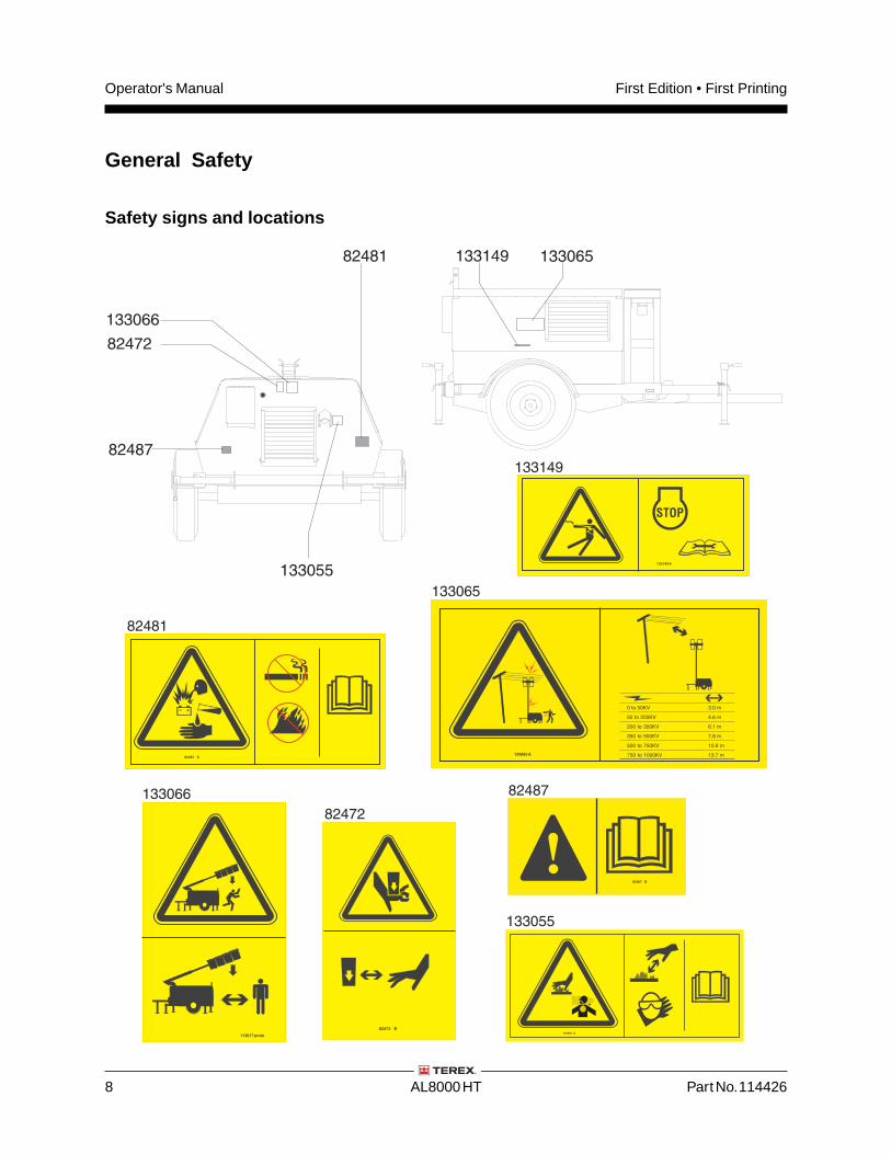
General Safety
Safety signs and locations
82472
82481
82481
82472
133055
133066
133066
133055
133065
82487
82487
133065
133149
133149
Part No. 114426 AL8000 HT 9
Operator's ManualFirst Edition • First Printing
Work Area Safety
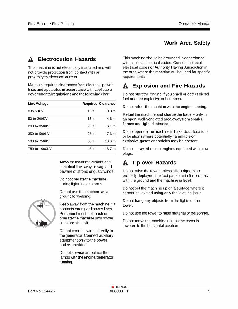
Electrocution HazardsThis machine is not electrically insulated and willnot provide protection from contact with orproximity to electrical current.
Maintain required clearances from electrical powerlines and apparatus in accordance with applicablegovernmental regulations and the following chart.
Line Voltage Required Clearance
0 to 50KV 10 ft 3.0 m
50 to 200KV 15 ft 4.6 m
200 to 350KV 20 ft 6.1 m
350 to 500KV 25 ft 7.6 m
500 to 750KV 35 ft 10.6 m
750 to 1000KV 45 ft 13.7 m
Allow for tower movement andelectrical line sway or sag, andbeware of strong or gusty winds.
Do not operate the machineduring lightning or storms.
Do not use the machine as aground for welding.
Keep away from the machine if itcontacts energized power lines.Personnel must not touch oroperate the machine until powerlines are shut off.
Do not connect wires directly tothe generator. Connect auxiliaryequipment only to the poweroutlets provided.
Do not service or replace thelamps with the engine/generatorrunning.
This machine should be grounded in accordancewith all local electrical codes. Consult the localelectrical codes or Authority Having Jurisdiction inthe area where the machine will be used for specificrequirements.
Explosion and Fire HazardsDo not start the engine if you smell or detect dieselfuel or other explosive substances.
Do not refuel the machine with the engine running.
Refuel the machine and charge the battery only inan open, well-ventilated area away from sparks,flames and lighted tobacco.
Do not operate the machine in hazardous locationsor locations where potentially flammable orexplosive gases or particles may be present.
Do not spray ether into engines equipped with glowplugs.
Tip-over HazardsDo not raise the tower unless all outriggers areproperly deployed, the foot pads are in firm contactwith the ground and the machine is level.
Do not set the machine up on a surface where itcannot be leveled using only the leveling jacks.
Do not hang any objects from the lights or thetower.
Do not use the tower to raise material or personnel.
Do not move the machine unless the tower islowered to the horizontal position.
Operator's Manual First Edition • First Printing
10 AL8000 HT Part No. 114426
Work Area Safety
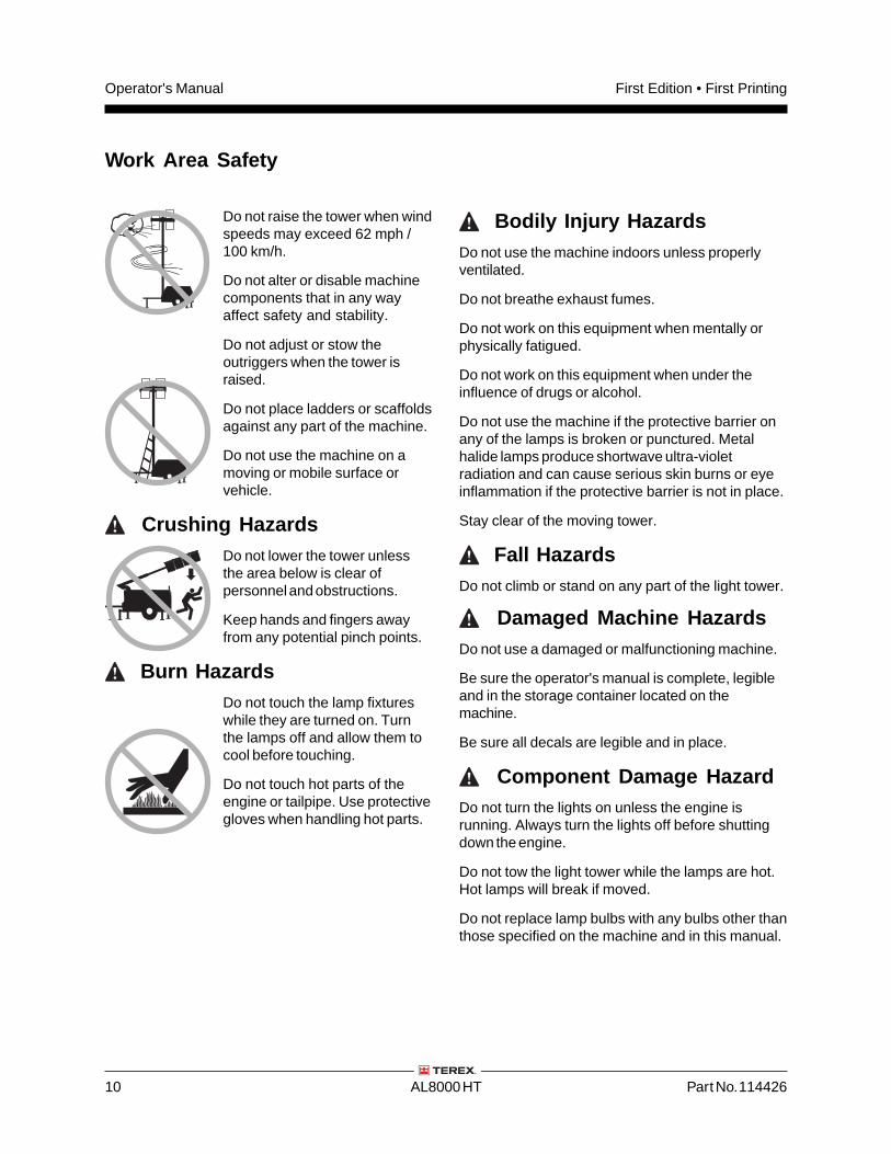
Do not raise the tower when windspeeds may exceed 62 mph /100 km/h.
Do not alter or disable machinecomponents that in any wayaffect safety and stability.
Do not adjust or stow theoutriggers when the tower israised.
Do not place ladders or scaffoldsagainst any part of the machine.
Do not use the machine on amoving or mobile surface orvehicle.
Crushing HazardsDo not lower the tower unlessthe area below is clear ofpersonnel and obstructions.
Keep hands and fingers awayfrom any potential pinch points.
Burn HazardsDo not touch the lamp fixtureswhile they are turned on. Turnthe lamps off and allow them tocool before touching.
Do not touch hot parts of theengine or tailpipe. Use protectivegloves when handling hot parts.
Bodily Injury HazardsDo not use the machine indoors unless properlyventilated.
Do not breathe exhaust fumes.
Do not work on this equipment when mentally orphysically fatigued.
Do not work on this equipment when under theinfluence of drugs or alcohol.
Do not use the machine if the protective barrier onany of the lamps is broken or punctured. Metalhalide lamps produce shortwave ultra-violetradiation and can cause serious skin burns or eyeinflammation if the protective barrier is not in place.
Stay clear of the moving tower.
Fall HazardsDo not climb or stand on any part of the light tower.
Damaged Machine HazardsDo not use a damaged or malfunctioning machine.
Be sure the operator's manual is complete, legibleand in the storage container located on themachine.
Be sure all decals are legible and in place.
Component Damage HazardDo not turn the lights on unless the engine isrunning. Always turn the lights off before shuttingdown the engine.
Do not tow the light tower while the lamps are hot.Hot lamps will break if moved.
Do not replace lamp bulbs with any bulbs other thanthose specified on the machine and in this manual.
Part No. 114426 AL8000 HT 11
Operator's ManualFirst Edition • First Printing
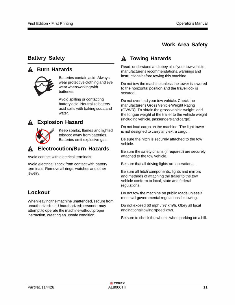
Battery Safety
Burn HazardsBatteries contain acid. Alwayswear protective clothing and eyewear when working withbatteries.
Avoid spilling or contactingbattery acid. Neutralize batteryacid spills with baking soda andwater.
Explosion HazardKeep sparks, flames and lightedtobacco away from batteries.Batteries emit explosive gas.
Electrocution/Burn HazardsAvoid contact with electrical terminals.
Avoid electrical shock from contact with batteryterminals. Remove all rings, watches and otherjewelry.
Towing HazardsRead, understand and obey all of your tow vehiclemanufacturer’s recommendations, warnings andinstructions before towing this machine.
Do not tow the machine unless the tower is loweredto the horizontal position and the travel lock issecured.
Do not overload your tow vehicle. Check themanufacturer's Gross Vehicle Weight Rating(GVWR). To obtain the gross vehicle weight, addthe tongue weight of the trailer to the vehicle weight(including vehicle, passengers and cargo).
Do not load cargo on the machine. The light toweris not designed to carry any extra cargo.
Be sure the hitch is securely attached to the towvehicle.
Be sure the safety chains (if required) are securelyattached to the tow vehicle.
Be sure that all driving lights are operational.
Be sure all hitch components, lights and mirrorsand methods of attaching the trailer to the towvehicle conform to local, state and federalregulations.
Do not tow the machine on public roads unless itmeets all governmental regulations for towing.
Do not exceed 60 mph / 97 km/h. Obey all localand national towing speed laws.
Be sure to chock the wheels when parking on a hill.
Work Area Safety
Lockout
When leaving the machine unattended, secure fromunauthorized use. Unauthorized personnel mayattempt to operate the machine without properinstruction, creating an unsafe condition.
Operator's Manual First Edition • First Printing
12 AL8000 HT Part No. 114426
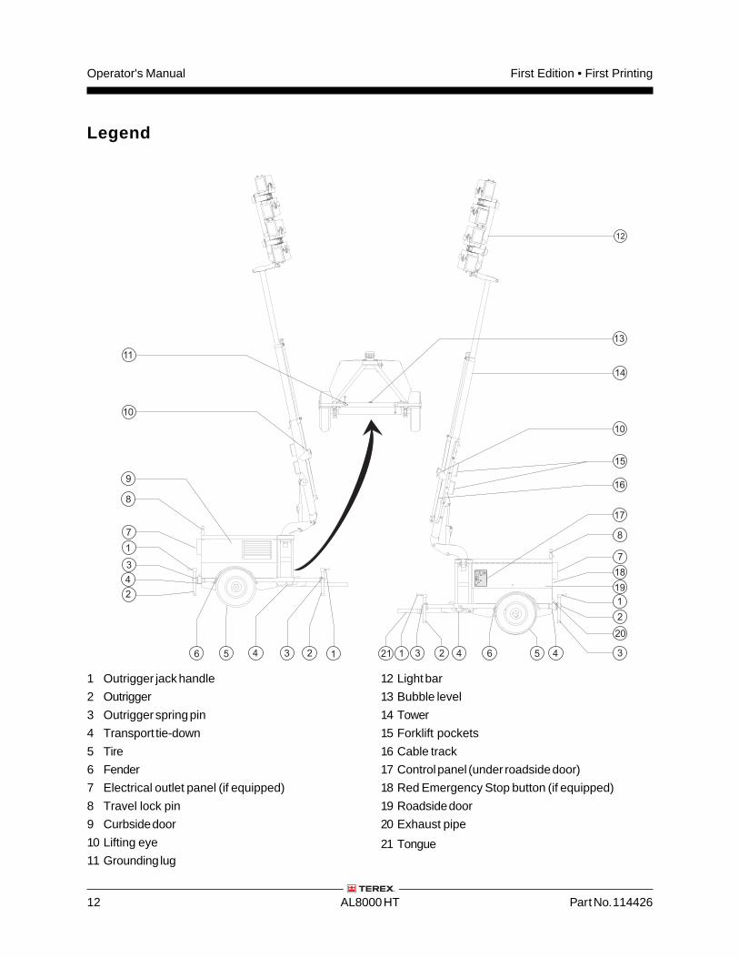
1 Outrigger jack handle
2 Outrigger
3 Outrigger spring pin
4 Transport tie-down
5 Tire
6 Fender
7 Electrical outlet panel (if equipped)
8 Travel lock pin
9 Curbside door
10 Lifting eye
11 Grounding lug
12 Light bar
13 Bubble level
14 Tower
15 Forklift pockets
16 Cable track
17 Control panel (under roadside door)
18 Red Emergency Stop button (if equipped)
19 Roadside door
20 Exhaust pipe
21 Tongue
Legend
4 4
4
4
7
7
17
3
333 2
2
2
21
1
1
1
5 56 6
18
19
20
21
9
8
10
11
10
12
13
14
15
8
16
Part No. 114426 AL8000 HT 13
Operator's ManualFirst Edition • First Printing
Auto Run P
1 2 3 4 5 6 7
P
R
h m1..7
0I
7
3
2
9 10
11
8
1
4
5
5
6
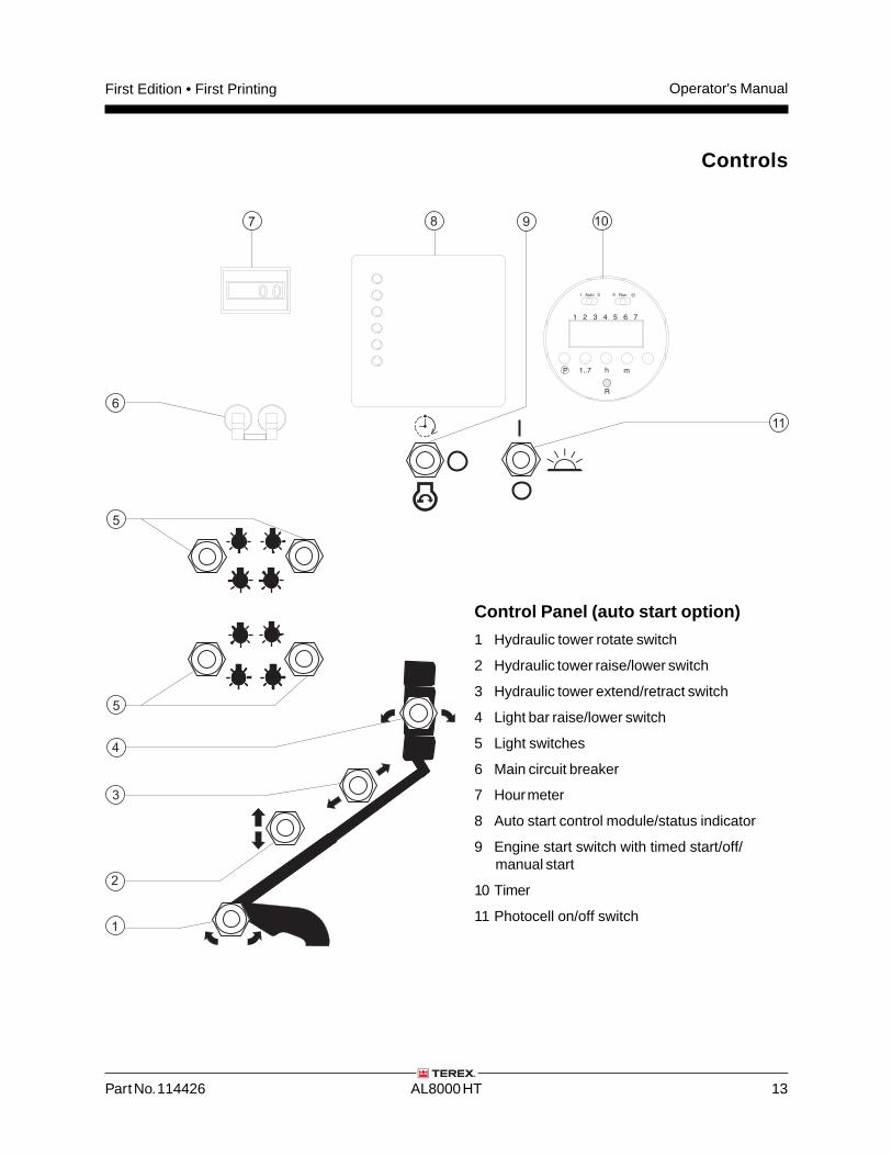
Controls
Control Panel (auto start option)
1 Hydraulic tower rotate switch
2 Hydraulic tower raise/lower switch
3 Hydraulic tower extend/retract switch
4 Light bar raise/lower switch
5 Light switches
6 Main circuit breaker
7 Hour meter
8 Auto start control module/status indicator
9 Engine start switch with timed start/off/manual start
10 Timer
11 Photocell on/off switch
Operator's Manual First Edition • First Printing
14 AL8000 HT Part No. 114426
Controls
Control Panel (auto start option)
1 Hydraulic tower rotate switch
Move the switch to the right and the tower willrotate to the right. Move switch to the left andthe tower will rotate to the left.
2 Hydraulic tower raise/lower switch
Move the switch up and the tower will raise.Move switch down and the tower will lower.
3 Hydraulic tower extend/retract switch
Move the switch to the right and the tower willextend. Move switch to the left and the towerwill retract.
4 Light bar raise/lower switch
Move the switch to the right and the light bar willraise. Move switch to the left and the light barwill lower.
5 Light switches
Move each switch to turn on the indicated light.Machines equipped with 4 lights: Each switchturns on one light.Machines equipped with 8 lights: Each switchturns on two lights at a time.
6 Main circuit breaker
Flip the main circuit breaker switch on beforeturning the individual light switches on.
7 Hour meter
The hour meter displays the number of hours themachine has operated.
8 Auto start control module/status indicator
Lights indicate failure or faults with the autostartsystem. Refer to the appropriate servicemanual.
9 Engine start switch
Move the switch to the timed start positionbefore setting the timer or engaging thephotocell switch.
Move the switch to the engine start position andthe engine will start after a 30-second delay.
Move the switch to the off position and theengine will be off.
10 Timer
The timer is used to automatically start theengine and turn on the lights at a preset time.
11 Photocell on/off switch
When the photocell is turned on, the lights willgo on at dusk and go off at daylight. The enginewill start prior to the lights going on.
Move the switch up to turn the photocell on.Move the switch down to turn the photocell off.
Part No. 114426 AL8000 HT 15
Operator's ManualFirst Edition • First Printing
7
3
2
9 108
1
4
5
5
6
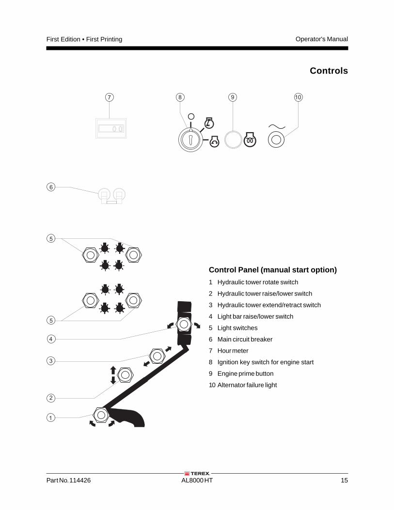
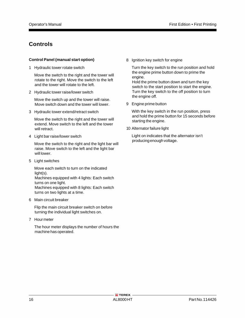
Control Panel (manual start option)
1 Hydraulic tower rotate switch
2 Hydraulic tower raise/lower switch
3 Hydraulic tower extend/retract switch
4 Light bar raise/lower switch
5 Light switches
6 Main circuit breaker
7 Hour meter
8 Ignition key switch for engine start
9 Engine prime button
10 Alternator failure light
Controls
Operator's Manual First Edition • First Printing
16 AL8000 HT Part No. 114426
Controls
Control Panel (manual start option)
1 Hydraulic tower rotate switch
Move the switch to the right and the tower willrotate to the right. Move the switch to the leftand the tower will rotate to the left.
2 Hydraulic tower raise/lower switch
Move the switch up and the tower will raise.Move switch down and the tower will lower.
3 Hydraulic tower extend/retract switch
Move the switch to the right and the tower willextend. Move switch to the left and the towerwill retract.
4 Light bar raise/lower switch
Move the switch to the right and the light bar willraise. Move switch to the left and the light barwill lower.
5 Light switches
Move each switch to turn on the indicatedlight(s).Machines equipped with 4 lights: Each switchturns on one light.Machines equipped with 8 lights: Each switchturns on two lights at a time.
6 Main circuit breaker
Flip the main circuit breaker switch on beforeturning the individual light switches on.
7 Hour meter
The hour meter displays the number of hours themachine has operated.
8 Ignition key switch for engine
Turn the key switch to the run position and holdthe engine prime button down to prime theengine.Hold the prime button down and turn the keyswitch to the start position to start the engine.Turn the key switch to the off position to turnthe engine off.
9 Engine prime button
With the key switch in the run position, pressand hold the prime button for 15 seconds beforestarting the engine.
10 Alternator failure light
Light on indicates that the alternator isn’tproducing enough voltage.
Part No. 114426 AL8000 HT 17
Operator's ManualFirst Edition • First Printing
Inspections
Do Not Operate Unless:
You learn and practice the principles of safemachine operation contained in this operator'smanual.
1 Avoid hazardous situations.
2 Always perform a pre-operationinspection.
Know and understand the pre-operationinspection before going on to the nextsection.
3 Always perform function tests prior to use.
4 Inspect the workplace.
5 Only use the machine as it was intended.
Pre-operation InspectionFundamentals
It is the responsibility of the operator to perform apre-operation inspection and routine maintenance.
The pre-operation inspection is a visual inspectionperformed by the operator prior to each work shift.The inspection is designed to discover if anythingis apparently wrong with a machine before theoperator performs the function tests.
The pre-operation inspection also serves todetermine if routine maintenance procedures arerequired. Only routine maintenance items specifiedin this manual may be performed by the operator.
Refer to the list on the next page and check eachof the items.
If damage or any unauthorized variation fromfactory delivered condition is discovered, themachine must be tagged and removed fromservice.
Repairs to the machine may only be made by aqualified service technician, according to themanufacturer's specifications. After repairs arecompleted, the operator must perform apre-operation inspection again before going on tothe function tests.
Scheduled maintenance inspections shall beperformed by qualified service technicians,according to the manufacturer's specifications.manual.
Operator's Manual First Edition • First Printing
18 AL8000 HT Part No. 114426
Inspections
Pre-operation Inspection
Be sure that the operator’s manual is complete,legible and in the storage container located onthe machine.
Be sure that all decals are legible and in place.See Inspections section.
Check for engine oil leaks and proper fluid level.Add oil if needed. See Maintenance section.
Check for engine coolant leaks and propercoolant level. Add coolant if necessary. SeeMaintenance section.
Check for battery fluid leaks and proper fluidlevel. Add distilled water if needed. SeeMaintenance section.
Check for proper tire pressure and lug nuttorque. Add air to tires if needed. SeeMaintenance section.
Check the following components or areas fordamage, improperly installed or missing parts andunauthorized modifications:
Electrical components, wiring and electricalcables
Tower components
Latches and pins
Tires and wheels
Trailer lights and reflectors
Outriggers, leveling jacks and foot pads
Nuts, bolts and other fasteners
Lamp fixtures and bulbs
Safety chains (if required)
Engine and related components
Fuel tank(s)
Generator
Check entire machine for:
Cracks in welds or structural components
Dents or damage to machine
Excessive rust, corrosion or oxidation
Be sure that all structural and other criticalcomponents are present and all associatedfasteners and pins are in place and properlytightened.
Be sure that the battery is in place and properlyconnected.
Part No. 114426 AL8000 HT 19
Operator's ManualFirst Edition • First Printing
Do Not Operate Unless:
You learn and practice the principles of safemachine operation contained in this operator'smanual.
1 Avoid hazardous situations.
2 Always perform a pre-operationinspection.
3 Always perform function tests prior touse.
Know and understand the function testsbefore going on to the next section.
4 Inspect the workplace.
5 Only use the machine as it was intended.
Function Test Fundamentals
The function tests are designed to discover anymalfunctions before the machine is put into service.The operator must follow the step-by-stepinstructions to test all machine functions.
A malfunctioning machine must never be used. Ifmalfunctions are discovered, the machine must betagged and removed from service. Repairs to themachine may only be made by a qualified servicetechnician, according to the manufacturer'sspecifications.
After repairs are completed, the operator mustperform a pre-operation inspection and functiontests again before putting the machine into service.
Inspections
Operator's Manual First Edition • First Printing
20 AL8000 HT Part No. 114426
Setup
1 Position the light tower at the desired work site.
2 Chock the wheels.
3 Disconnect the trailer lights and safety chains.
4 Pull the release pin on the tongue jack androtate into place.
5 Turn the jack handle to lower the foot pad andraise the tongue of the machine enough to clearthe tow vehicle.
6 Release the spring pin on the front and backoutriggers and slide each outrigger out until thespring pin engages. Rotate the outriggers intoposition.
7 Turn the outrigger jack handles to level themachine and raise the wheels off the ground.Level the machine using only the leveling jacks.
8 Check the bubble level on the front of themachine to make sure the machine is level.
9 Drive the grounding rod into the groundand connect to the grounding lug onthe chassis near the base of the tower.
10 Manually start the engine. SeeOperating Instructions section.
Test Emergency Stop(if equipped)
11 Push in the red Emergency Stop button.
Result: The engine should shut off.
12 Test each tower and light function.
Result: All functions should not operate.
13 Pull out the red Emergency Stop button tothe on position.
14 Start the engine.
Inspections
Test the Tower Operation
15 Move each toggle switch according to themarkings on the tower control panel.
Result: All tower functions should operate.
Test the Lights
Note: Make sure the engine is running.
16 Turn on the main circuit breaker switch.
17 Turn on the light switches.
Result: All lights should come on.
Note: If the lights are already hot from beingoperated, they will require 5-10 minutes to coolbefore they will come on again.
Part No. 114426 AL8000 HT 21
Operator's ManualFirst Edition • First Printing
Workplace Inspection
Be aware of and avoid the following hazardoussituations:
• drop-offs or holes
• bumps, floor obstructions or debris
• sloped surfaces
• unstable or slippery surfaces
• overhead obstructions and high voltageconductors
• hazardous locations
• inadequate surface support to withstand all loadforces imposed by the machine
• wind and weather conditions
• the presence of unauthorized personnel
• other possible unsafe conditions
Do Not Operate Unless:
You learn and practice the principles of safemachine operation contained in this operator'smanual.
1 Avoid hazardous situations.
2 Always perform a pre-operationinspection.
3 Always perform function tests prior to use.
4 Inspect the workplace.
Know and understand the workplaceinspection before going on to the nextsection.
5 Only use the machine as it was intended.
Fundamentals
The workplace inspection helps the operatordetermine if the workplace is suitable for safemachine operation. It should be performed by theoperator prior to moving the machine to theworkplace.
It is the operator's responsibility to read andremember the workplace hazards, then watch forand avoid them while moving, setting up andoperating the machine.
Inspections
Operator's Manual First Edition • First Printing
22 AL8000 HT Part No. 114426
Inspections
Part No. Description Quantity
28159 Label - Diesel 1
28161 Warning - Crushing Hazard 3
31788 Danger - Battery Safety 1
52475 Label - Tie-down Point 4
72086 Label - Lifting Eye 2
72143 Label - Emergency Stop 1
97602 Warning - Explosion Hazard, Ether 2
97666 Warning - Improper Use Hazard 1
114258 Danger - No Smoking 1
114430 Notice - Turn Off Lights 1
114431 Danger - Electrocution Hazard 2
114432 Danger - General Safety 1
114433 Instructions - Operating Instructions 1
114447 Cosmetic - Terex, 33 in 1
114448 Cosmetic - Terex, 50 in 1
114450 Cosmetic - AL8000 HT 2
114456 Control Panel, Hydraulic Tower 1
114457 Control Panel, Auto Engine Start 1
114458 Control Panel, Manual Engine Start 1
114460 Label - Lights (Patch) 1
114463 Instructions - Setup and Transport 2
114464 Label - Travel Lock 2
Part No. Description Quantity
114466 Receptacle Panel (option) 1
133012 Danger - Carbon Monoxide Hazard 1
133016 Danger - Hazardous Voltage, Lights 2
133020 Label - Tire Specifications, U.S. 2
133017 Warning - Crushing Hazard, Tower 1
133062 Label - Grounding Lug 1
133063 Label - Transport Tie-down Diagram 2
133097 Label - Tire Specifications, Australia 2
133148 Danger - Hazardous Voltage 2
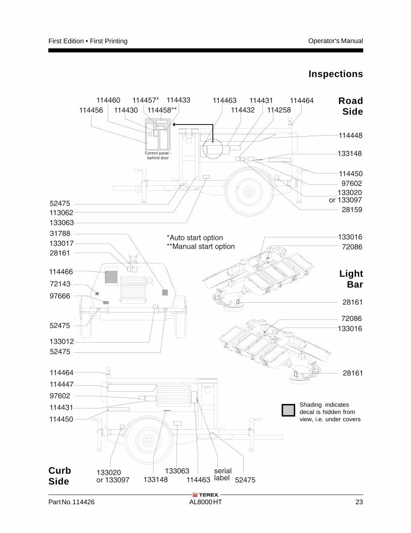
Inspection for Decals with Words
Determine whether the decals on your machinehave words or symbols. Use the appropriateinspection to verify that all decals are legible and inplace.
Part No. 114426 AL8000 HT 23
Operator's ManualFirst Edition • First Printing
72143
28161
28161
28161
72086
7208652475
52475
97602
52475
*Auto start option**Manual start option
133063
133063133148
133148
133020or 133097
133020or 133097
114463
114432
114431
Control panel -behind door
52475
113062
97602
114258
114464
28159
133012
133017
133016
133016
114466
114447
114464
114463
seriallabel
114450
114450
114431
114448
97666
31788
114456
114460
114430
114457*
114458**
114433
Inspections
Shading indicatesdecal is hidden fromview, i.e. under covers
LightBar
RoadSide
CurbSide
Operator's Manual First Edition • First Printing
24 AL8000 HT Part No. 114426
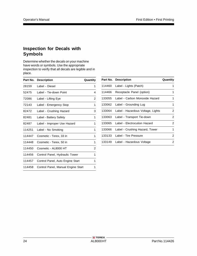
Part No. Description Quantity
28159 Label - Diesel 1
52475 Label - Tie-down Point 4
72086 Label - Lifting Eye 2
72143 Label - Emergency Stop 1
82472 Label - Crushing Hazard 3
82481 Label - Battery Safety 1
82487 Label - Improper Use Hazard 1
114251 Label - No Smoking 1
114447 Cosmetic - Terex, 33 in 1
114448 Cosmetic - Terex, 50 in 1
114450 Cosmetic - AL8000 HT 2
114456 Control Panel, Hydraulic Tower 1
114457 Control Panel, Auto Engine Start 1
114458 Control Panel, Manual Engine Start 1
Part No. Description Quantity
114460 Label - Lights (Patch) 1
114466 Receptacle Panel (option) 1
133055 Label - Carbon Monoxide Hazard 1
133062 Label - Grounding Lug 1
133064 Label - Hazardous Voltage, Lights 2
133063 Label - Transport Tie-down 2
133065 Label - Electrocution Hazard 2
133066 Label - Crushing Hazard, Tower 1
133133 Label - Tire Pressure 2
133149 Label - Hazardous Voltage 2
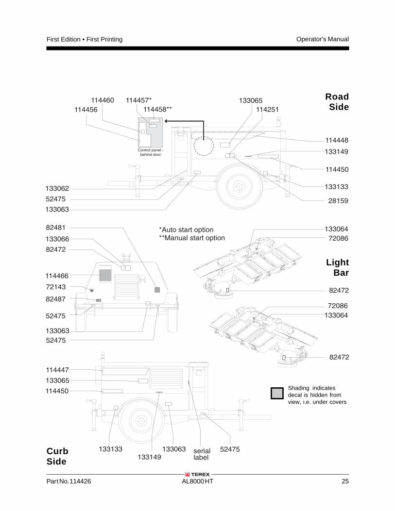
Inspection for Decals withSymbols
Determine whether the decals on your machinehave words or symbols. Use the appropriateinspection to verify that all decals are legible and inplace.
Part No. 114426 AL8000 HT 25
Operator's ManualFirst Edition • First Printing
72143
82472
52475
82487
82481
52475
52475
133063
133062
133063
133065
Control panel -behind door
52475
114251
28159
133063
133066
114466
114447
114450
133133
133133
114450
133065
114448
114456
114460 114457*
114458**
82472
82472
72086
72086
133064
133064*Auto start option**Manual start option
seriallabel133149
133149
Shading indicatesdecal is hidden fromview, i.e. under covers
LightBar
RoadSide
CurbSide
Operator's Manual First Edition • First Printing
26 AL8000 HT Part No. 114426
Operating Instructions
Do Not Operate Unless:
You learn and practice the principles of safemachine operation contained in this operator'smanual.
1 Avoid hazardous situations.
2 Always perform a pre-operationinspection.
3 Always perform function tests prior to use.
4 Inspect the workplace.
5 Only use the machine as it was intended.
Fundamentals
The Operating Instructions section providesinstructions for each aspect of machine operation.It is the operator's responsibility to follow all thesafety rules and instructions in the operator'smanual.
Only trained and authorized personnel should bepermitted to operate a machine. If more than oneoperator is expected to use a machine at differenttimes in the same work shift, they must all bequalified operators and are all expected to follow allsafety rules and instructions in the operator's,safety and responsibilities manuals. That meansevery new operator should perform a pre-operationinspection, function tests, and a workplaceinspection before using the machine.
Part No. 114426 AL8000 HT 27
Operator's ManualFirst Edition • First Printing
Setup
Make sure the machine is set up according to theSetup procedure in the Function Tests section.
Start the Engine
Note: The main circuit breaker and the lightswitches must be off before starting the engine.
Note: If the machine is equipped with dual fueltanks, there must be fuel in both tanks in order tostart the engine.
If equipped: Pull out the red Emergency Stopbutton on the back panel of the light tower cabinet.
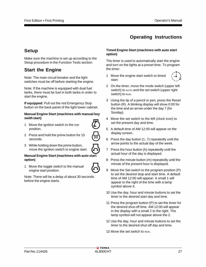
Manual Engine Start (machines with manual keyswith start)
1 Move the ignition switch to the runposition.
2 Press and hold the prime button for 15seconds.
3 While holding down the prime button,move the ignition switch to engine start.
Manual Engine Start (machines with auto startoption)
1 Move the toggle switch to the manualengine start position.
Note: There will be a delay of about 30 secondsbefore the engine starts.
Operating Instructions
Timed Engine Start (machines with auto startoption)
The timer is used to automatically start the engineand turn on the lights at a preset time. To programthe timer:
1 Move the engine start switch to timedstart.
2 On the timer, move the mode switch (upper leftswitch) to AUTO and the set switch (upper rightswitch) to RUN.
3 Using the tip of a pencil or pen, press the Resetbutton (R). A blinking display will show 0:00 forthe time and an arrow under the day 7 (forSunday).
4 Move the set switch to the left (clock icon) toset the present day and time.
5 A default time of AM 12:00 will appear on thedisplay screen.
6 Press the day button (1..7) repeatedly until thearrow points to the actual day of the week.
7 Press the hour button (h) repeatedly until theactual hour of the day is displayed.
8 Press the minute button (m) repeatedly until theminute of the present hour is displayed.
9 Move the Set switch to the program position (P)to set the desired stop and start time. A defaulttime of AM 12:00 will appear. A small 1 willappear to the right of the time with a lampsymbol above it.
10 Use the day, hour and minute buttons to set thetimer to the desired start day and time.
11 Press the program button (P) to set the timer forthe desired shut-off time. AM 12:00 will appearin the display with a small 2 to the right. Thelamp symbol will not appear above the 2.
12 Use the day, hour and minute buttons to set thetimer to the desired shut-off day and time.
13 Move the set switch to RUN.
Operator's Manual First Edition • First Printing
28 AL8000 HT Part No. 114426
Operating Instructions
Photocell (machines with auto start option)
When the photocell is turned on, the lights will goon at dusk and go off at daylight. The engine willautomatically start prior to the lights going on.
When the photocell option is in use and thephotocell has detected a low enough light level tostart the light tower, the engine running light on theLED panel will flash for 30 seconds before theengine starts.
To turn on the photocell:
1 Move the engine start switch to timedstart.
2 Move the photocell switch to on.
Operation of Tower
1 Make sure the engine is running.
Note: Operating the tower with the engine off willrun down the battery.
2 Move the appropriate toggle switch according tothe markings on the control panel to rotate thetower, raise and lower the tower, extend andretract the tower, and raise and lower the lightbar.
Manual Operation of Lights
Note: The engine must be running before the lightsare turned on.
1 Turn on the main circuit breaker switches on thecontrol panel.
2 Turn on the lights using the individual lightswitches.
Models with four lights: Each switch turns on one ofthe lights.
Models with eight lights: Each switch turns on twoof the lights at one time.
3 Turn the lights off by turning the individual lightswitches to the off position. Make sure thelights are turned off before shutting down theengine.
Grounding
A grounding rod is located insidethe door on the road side of themachine.
Drive the rod into the ground andconnect it to the grounding luglocated on the chassis near thebase of the tower.
Electrical Outlets (if equipped)
Electrical outlets are located behind the panel onthe rear of the light tower cabinet.
Part No. 114426 AL8000 HT 29
Operator's ManualFirst Edition • First Printing
Towing Information
Driving a vehicle/trailer combination is differentfrom driving a vehicle alone.
Inspect all connections at each stop.
All tires must be properly inflated. Do notoverinflate the tires. Tire pressures go up duringdriving. Checking the tire pressure when the tiresare warm will give you an inaccurate pressurereading.
Increase the distance between your vehicle and thevehicle in front of you to twice the normal followingdistance when towing a trailer. Allow more followingdistance in adverse weather.
Slow down for downgrades and shift yourtransmission into a lower gear.
Slow down for curves, hazardous road conditions,freeway exits, and when driving in adverse weather.
Heavy winds, excessive speed, load shifting orpassing vehicles can cause a trailer to sway whiledriving. If this occurs, do not brake, speed up orturn the steering wheel. Turning the steering wheelor applying the brakes can cause the vehicle andtrailer to jackknife. Let up on the gas pedal andkeep the steering wheel straight.
If the vehicle and/or trailer travels off the pavedroad, hold the steering wheel firmly and let up onthe gas pedal. Do not apply the brakes. Do not turnsharply. Slow down to under 25 mph / 40 km/h.Gradually turn the steering wheel to get back on theroad. Proceed with caution when entering traffic.
When passing other vehicles, be sure to leaveenough room for the extra length of the trailer. Youwill need to go much farther beyond the passedvehicle before you can return to your lane.
Avoid jerky or sudden movements when turning.
Operating Instructions
Towing
1 Fully retract and lower the tower.
2 Lower the light bar to the stowed position.
3 Make sure the travel lock pin is securely lockedin place.
4 Make sure the covers are closed and secured.
5 Pull the spring pins on each outrigger to rotatethe outrigger up and slide it into the stowedposition.
6 Raise the tongue of the machine by turning thetongue jack handle.
7 Position the transport vehicle under the coupleron the tongue of the machine.
8 Open the latch on the coupler.
7 Turn the tongue jack handle to lower the tongue.
9 Close the latch on the coupler.
10 Rotate the tongue jack to the stowed positionand secure with the lock pin.
11 Attach the safety chains (if required).
12 Connect and test the trailer lights.
Operator's Manual First Edition • First Printing
30 AL8000 HT Part No. 114426
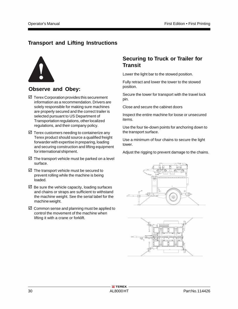
Securing to Truck or Trailer forTransit
Lower the light bar to the stowed position.
Fully retract and lower the tower to the stowedposition.
Secure the tower for transport with the travel lockpin.
Close and secure the cabinet doors
Inspect the entire machine for loose or unsecureditems.
Use the four tie-down points for anchoring down tothe transport surface.
Use a minimum of four chains to secure the lighttower.
Adjust the rigging to prevent damage to the chains.
Transport and Lifting Instructions
Observe and Obey:Terex Corporation provides this securementinformation as a recommendation. Drivers aresolely responsible for making sure machinesare properly secured and the correct trailer isselected pursuant to US Department ofTransportation regulations, other localizedregulations, and their company policy.
Terex customers needing to containerize anyTerex product should source a qualified freightforwarder with expertise in preparing, loadingand securing construction and lifting equipmentfor international shipment.
The transport vehicle must be parked on a levelsurface.
The transport vehicle must be secured toprevent rolling while the machine is beingloaded.
Be sure the vehicle capacity, loading surfacesand chains or straps are sufficient to withstandthe machine weight. See the serial label for themachine weight.
Common sense and planning must be applied tocontrol the movement of the machine whenlifting it with a crane or forklift.
Part No. 114426 AL8000 HT 31
Operator's ManualFirst Edition • First Printing
Transport and Lifting Instructions
Observe and Obey:Only qualified riggers should rig and lift themachine.
Be sure the crane capacity, loading surfacesand straps or lines are sufficient to withstandthe machine weight. See the serial plate for themachine weight.
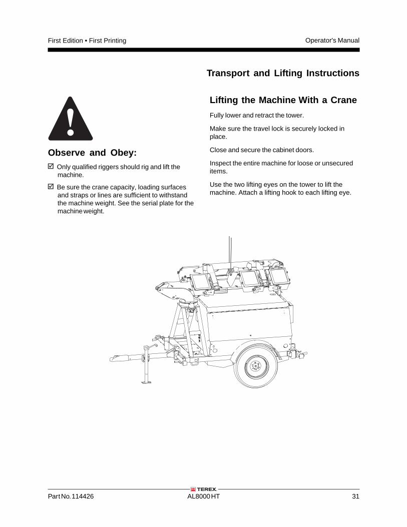
Lifting the Machine With a Crane
Fully lower and retract the tower.
Make sure the travel lock is securely locked inplace.
Close and secure the cabinet doors.
Inspect the entire machine for loose or unsecureditems.
Use the two lifting eyes on the tower to lift themachine. Attach a lifting hook to each lifting eye.
Operator's Manual First Edition • First Printing
32 AL8000 HT Part No. 114426
Check the Engine Coolant Level
Maintaining the engine coolant at the proper level isessential to engine service life. Improper coolantlevel will affect the engine's cooling capability anddamage engine components. Daily checks willallow the inspector to identify changes in coolantlevel that might indicate cooling system problems.
Burn hazard. Beware of hot engine parts andcoolant. Contact with hot engine parts and/orcoolant may cause severe burns.
Note: Do not remove the radiator cap.
1 Check the fluid level in the coolant recoverytank.
2 Add fluid as needed.
Maintenance
Observe and Obey:Only routine maintenance items specified in thismanual shall be performed by the operator.
Scheduled maintenance inspections shall becompleted by qualified service technicians,according to the manufacturer's specificationsand the requirements specified in theresponsibilities manual.
Use only Terex approved replacement parts.
Maintenance Symbols Legend
The following symbols have been used in thismanual to help communicate the intent of theinstructions. When one or more of the symbolsappear at the beginning of a maintenanceprocedure, it conveys the meaning below.
Indicates that tools will be required toperform this procedure.
Indicates that new parts will be required toperform this procedure.
Check the Engine Oil Level
Maintaining the proper engine oil level is essentialto good engine performance and service life.Operating the machine with an improper oil levelcan damage engine components.
1 Check the oil level with the engine off.
2 Check the oil level dipstick. Add oil if needed.
Kubota 13.6 HP
Oil viscosity requirements See engine manual
Part No. 114426 AL8000 HT 33
Operator's ManualFirst Edition • First Printing
Maintenance
Scheduled MaintenanceMaintenance performed quarterly, annually andevery two years must be completed by a persontrained and qualified to perform maintenance on thismachine according to the procedures found in theservice manual for this machine.
Machines that have been out of service for morethan three months must receive the quarterlyinspection before they are put back into service.
Check the Tires and Wheels
Bodily injury hazard. An over-inflated tire canexplode and may cause death or serious injury.
Collision hazard. An excessively worn tire cancause poor handling and continued use could resultin tire failure.
Tip-over hazard. Do not use temporary flat tirerepair products.
Maintaining the tires and wheels in good conditionis essential to safe operation and goodperformance. Tire and/or wheel failure could resultin a machine tip-over. Component damage mayalso result if problems are not discovered andrepaired in a timely fashion.
1 Check the tire surface and sidewalls for cuts,cracks, punctures and uneven or excessivetread wear. Replace the tire if uneven orexcessive tread wear is found.
2 Check each wheel for damage, bends andcracks. Replace the wheel if any damage isfound.
Note: Tires and wheels must be replaced with tiresand wheels of the specifications listed.
3 Check each tire with an air pressure gauge andadd air as needed.
4 Check the torque of each lug nut.
Tire Specifications, U.S.
Tire size ST205/75R15 Load C
Lug nut torque 80 ft/lbs 108 Nm
Tire pressure (cold) 50 psi 3.4 bar
Tire Specifications, Australia
Tire size 7.5R16 C 112/110L
Lug nut torque 80 ft/lbs 108 Nm
Tire pressure (cold) 75 psi 5.2 bar
Operator's Manual First Edition • First Printing
34 AL8000 HT Part No. 114426
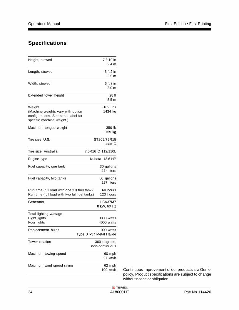
Specifications
Continuous improvement of our products is a Geniepolicy. Product specifications are subject to changewithout notice or obligation.
Height, stowed 7 ft 10 in 2.4 m
Length, stowed 8 ft 2 in2.5 m
Width, stowed 6 ft 8 in2.0 m
Extended tower height 28 ft8.5 m
Weight 3162 lbs(Machine weights vary with option 1434 kgconfigurations. See serial label forspecific machine weight.)
Maximum tongue weight 350 lb159 kg
Tire size, U.S. ST205/75R15Load C
Tire size, Australia 7.5R16 C 112/110L
Engine type Kubota 13.6 HP
Fuel capacity, one tank 30 gallons 114 liters
Fuel capacity, two tanks 60 gallons227 liters
Run time (full load with one full fuel tank) 60 hoursRun time (full load with two full fuel tanks) 120 hours
Generator LSA37M78 kW, 60 Hz
Total lighting wattageEight lights 8000 wattsFour lights 4000 watts
Replacement bulbs 1000 wattsType BT-37 Metal Halide
Tower rotation 360 degrees,non-continuous
Maximum towing speed 60 mph97 km/h
Maximum wind speed rating 62 mph100 km/h
Part No. 114426 AL8000 HT 35
Operator's ManualFirst Edition • First Printing
Reporting Safety Defects
Terex Light Construction Division590 Huey RoadRock Hill, SC 29732
Reporting Safety Defects
If you believe that your vehicle has a defect whichcould cause a crash or could cause injury or death,you should immediately inform the NationalHighway Traffic Safety Administration (NHTSA) inaddition to Genie Industries.
If NHTSA receives similar complaints, it may openan investigation, and if it finds that a safety defectexists in a group of vehicles, it may order a recalland remedy campaign. However, NHTSA cannotbecome involved in any individual problemsbetween you, your dealer or Genie Industries.
To contact NHTSA you may either call the AutoSafety Hotline toll-free at 1-800-424-9393 (366-0123in Washington DC area) or write to:
NHTSAU.S. Department of Transportation400 7th Street SW, (NSA-11)Washington DC 20590
You can also obtain information about motorvehicle safety from the Hotline.
Dis
trib
ute
d B
y:
Genie North AmericaPhone 425.881.1800
Toll Free USA and Canada
800.536.1800
Fax 425.883.3475
Genie Australia Pty Ltd.Phone +61 7 3375 1660
Fax +61 7 3375 1002
Genie ChinaPhone +86 21 53852570
Fax +86 21 53852569
Genie MalaysiaPhone +65 98 480 775
Fax +65 67 533 544
Genie JapanPhone +81 3 3453 6082
Fax +81 3 3453 6083
Genie KoreaPhone +82 25 587 267
Fax +82 25 583 910
Genie BrasilPhone +55 11 41 665 755
Fax +55 11 41 665 754
Genie HollandPhone +31 183 581 102
Fax +31 183 581 566
Genie ScandinaviaPhone +46 31 575100
Fax +46 31 579020
Genie FrancePhone +33 (0)2 37 26 09 99
Fax +33 (0)2 37 26 09 98
Genie IbericaPhone +34 93 579 5042
Fax +34 93 579 5059
Genie GermanyPhone +49 (0)4202 88520
Fax +49 (0)4202 8852-20
Genie U.K.Phone +44 (0)1476 584333
Fax +44 (0)1476 584334
Genie Mexico CityPhone +52 55 5666 5242
Fax +52 55 5666 3241
California Proposition 65
WarningThe exhaust from this product
contains chemicals known to
the State of California to
cause cancer, birth defects
or other reproductive harm.