Embed Size (px)
Citation preview
PROGRAMMING MANUALα2 SIMPLE APPLICATION CONTROLLER
α2 Simple Application Controllers
Foreword• This manual contains text, diagrams and explanations which will guide the reader in the
correct programming and operation of the α2 series controller.• Before attempting to install or use the α2 Series Controller this manual should be read and
understood.• If in doubt at any stage of the installation of the α2 Series Controller always consult a
professional electrical engineer who is qualified and trained to local and national standards which apply to the installation site.
• If in doubt about the operation or use of the α2 Series Controller please consult the nearest Mitsubishi Electric distributor.
• This manual is subject to change without notice.

i
α2 SIMPLE APPLICATION CONTROLLERS
PROGRAMMING MANUAL
Manual number : JY992D97101
Manual revision : B
Date : Oct. 2003
α2 Simple Application Controllers

FAX BACK
Mitsubishi has a world wide reputation for its efforts in continually developing and pushing backthe frontiers of industrial automation. What is sometimes overlooked by the user is the careand attention to detail that is taken with the documentation. However, to continue this processof improvement, the comments of the Mitsubishi users are always welcomed. This page hasbeen designed for you, the reader, to fill in your comments and fax them back to us. We lookforward to hearing from you.
Fax numbers: Your name: ...................................................
Mitsubishi Electric.... .....................................................................
America (01) 847-478-2253 Your company: .............................................
Australia (02) 638-7072 .....................................................................
Germany (0 21 02) 4 86-1 12 Your location:................................................
Spain (34) 93-589-1579 .....................................................................
United Kingdom (01707) 278-695
Please tick the box of your choice
What condition did the manual arrive in? !Good !Minor damage !Unusable
Will you be using a folder to store the manual?!Yes !No
What do you think to the manual presentation?!Tidy !Unfriendly
Are the explanations understandable? !Yes !Not too bad !Unusable
Which explanation was most difficult to understand: ......................................................................................................................................................................................................................
Are there any diagrams which are not clear? !Yes !No
If so,which: ..................................................................................................................................
What do you think to the manual layout? !Good !Not too bad !Unhelpful
If there one thing you would like to see improved, what is it? .............................................................................................................................................................................................................................................................................................................................................................
Could you find the information you required easily using the index and/or the contents, ifpossible please identify your experience: ...................................................................................................................................................................................................................................................................................................................................................................................................................................................................................................................................................................................................................................................................................................
Do you have any comments in general about the Mitsubishi manuals? .....................................................................................................................................................................................................................................................................................................................................................................................................................................................................................................................................................................................................................................................
Thank you for taking the time to fill out this questionnaire. We hope you found both the productand this manual easy to use.
α2 Simple Application Controllers
ii
α2 Simple Application Controllers
iii
Guidelines for the safety of the user and protection of α2 Simple Application controllers
This manual provides information for the use of α2 Simple Application controllers. The manualhas been written to be used by trained and competent personnel. The definition of such aperson or persons is as follows;
a) Any engineer who is responsible for the planning, design and construction of automaticequipment using the product associated with this manual should be of a competentnature, trained and qualified to the local and national standards required to fulfill thatrole. These engineers should be fully aware of all aspects of safety with regards toautomated equipment.
b) Any commissioning or service engineer must be of a competent nature, trained andqualified to the local and national standards required to fulfill that job. These engineersshould also be trained in the use and maintenance of the completed product. Thisincludes being completely familiar with all associated documentation for the said product.All maintenance should be carried out in accordance with established safety practices.
c) All operators of the completed equipment (see Note) should be trained to use thisproduct in a safe manner in compliance to established safety practices. The operatorsshould also be familiar with documentation which is associated with the operation of thecompleted equipment.
Note : Note: the term ‘completed equipment’ refers to a third party constructed device whichcontains or uses the product associated with this manual.
Notes on the Symbols Used in this Manual
At various times throughout this manual certain symbols will be used to highlight points ofinformation which are intended to ensure the users personal safety and protect the integrity ofequipment. Whenever any of the following symbols are encountered its associated note mustbe read and understood. Each of the symbols used will now be listed with a brief description ofits meaning.
Hardware warnings
1 ) Indicates that the identified danger WILL cause physical and property damage.
2 ) Indicates that the identified danger could POSSIBLY cause physical and propertydamage.
3 ) Indicates a point of further interest or further explanation.
Software warning
4 ) Indicates special care must be taken when using this element of software.
5 ) Indicates a special point which the user of the associate software element shouldbe aware of.
6 ) Indicates a point of interest or further explanation.

α2 Simple Application Controllers
iv

v
Table of Contents
Safety Guidelines ................................................................................ iii
1. Introduction ...............................................................................1-11.1 Special Features of the Controller ........................................................ 1-11.2 Model Name .......................................................................................... 1-2
2. Function Block Programming ....................................................2-12.1 Block Type and the FBD base .............................................................. 2-1
2.1.1 Inputs ........................................................................................... 2-22.1.2 Front Panel Keys .......................................................................... 2-22.1.3 System Memory Bits .................................................................... 2-32.1.4 Function Blocks ............................................................................ 2-32.1.5 Outputs ........................................................................................ 2-42.1.6 Function Block Diagram (FBD) base ............................................ 2-4
2.2 Programming Methods .......................................................................... 2-52.2.1 Direct Programming ..................................................................... 2-52.2.2 AL-PCS/WIN-E Programming Software Ver 2.00 and upwards ... 2-5
3. System Menu ............................................................................3-13.1 Menu Options Instructions .................................................................... 3-13.2 The Stop Mode ..................................................................................... 3-2
3.2.1 Top Menu ..................................................................................... 3-23.2.2 The “Others... ............................................................................... 3-4
3.3 The Run Mode Top Menu ................................................................... 3-103.4 The Edit Menu ..................................................................................... 3-153.5 The Function Block Edit Menu ............................................................ 3-153.6 Option Screen Setup ........................................................................... 3-16
3.6.1 ProgEdit ..................................................................................... 3-163.6.2 Change the Language Setting ................................................... 3-163.6.3 ClockSET ................................................................................... 3-163.6.4 RadioClock - DCF77 Decoding .................................................. 3-173.6.5 SummerTime .............................................................................. 3-183.6.6 DispPass .................................................................................... 3-193.6.7 Password ................................................................................... 3-203.6.8 Serial Com ................................................................................. 3-203.6.9 Memory cassette ........................................................................ 3-213.6.10 Analog Inputs ........................................................................... 3-22
3.7 LCD Displays ...................................................................................... 3-233.7.1 Image Table ............................................................................... 3-233.7.2 LCD Function ............................................................................. 3-23
3.8 Block Items ......................................................................................... 3-243.8.1 Input Blocks ............................................................................... 3-243.8.2 Function Blocks .......................................................................... 3-243.8.3 Output Blocks ............................................................................. 3-243.8.4 Connected Blocks ...................................................................... 3-24
α2 Simple Application Controllers
α2 Series Applications Controller
vi
4. Direct Programming ..................................................................4-14.1 Block Availability ................................................................................... 4-14.2 Connecting Blocks ................................................................................ 4-1
4.2.1 To connect the blocks from the left (signal provider) block to right (signal receiver) block. ................................................................ 4-14.2.2 To connect the blocks from the right (signal receiver) block to left (signal provider) block. ................................................................ 4-2
4.3 Disconnect Two Blocks ......................................................................... 4-24.4 Methods to Create a Function Block ..................................................... 4-3
4.4.1 New FB ........................................................................................ 4-34.4.2 AddFB .......................................................................................... 4-3
4.5 Function Block Editing .......................................................................... 4-34.5.1 Setup Function Block ................................................................... 4-34.5.2 Change No. (of a Function Block) ................................................ 4-34.5.3 Delete FB ..................................................................................... 4-3
4.6 Movement between Function Blocks .................................................... 4-44.6.1 Movement Between Unconnected Blocks .................................... 4-44.6.2 Movement Between Connected Blocks ....................................... 4-44.6.3 The Jump Command .................................................................... 4-4
4.7 Using Keys as Inputs ............................................................................ 4-44.8 The Monitor Mode ................................................................................. 4-5
4.8.1 Monitor/Update Function Block Values ........................................ 4-54.8.2 Forcing Outputs ON/OFF ............................................................. 4-64.8.3 Add/Delete Function Blocks in the Monitor Mode ........................ 4-6
5. The Logic Function Blocks ........................................................5-15.1 The AND Block ..................................................................................... 5-25.2 The OR Block ........................................................................................ 5-35.3 The NOT Block ..................................................................................... 5-45.4 The XOR Block (Exclusive OR) ............................................................ 5-45.5 The NAND Block (Not AND) ................................................................. 5-55.6 The NOR Block (Not OR) ...................................................................... 5-6
α2 Series Applications Controller
vii
6. Function Blocks .........................................................................6-16.1 Definitions ............................................................................................. 6-66.2 Abbreviations ........................................................................................ 6-66.3 Boolean block ....................................................................................... 6-76.4 Set/Reset Block .................................................................................... 6-96.5 Pulse Block ......................................................................................... 6-116.6 Alternate Block .................................................................................... 6-136.7 Delay Block ......................................................................................... 6-146.8 One Shot Block ................................................................................... 6-166.9 Flicker Block ........................................................................................ 6-186.10 TimeSW Block .................................................................................. 6-21
6.10.1 Setting the First Time Switch ................................................... 6-216.10.2 For the Date operation: ............................................................ 6-226.10.3 For the Weekly Operation: ....................................................... 6-226.10.4 To Enter New Time Switches ................................................... 6-226.10.5 To Edit Time Switches ............................................................. 6-236.10.6 To Delete Time Switch Data .................................................... 6-23
6.11 Counter Block ................................................................................... 6-246.12 Up/Down Counter Block .................................................................... 6-256.13 Compare Block ................................................................................. 6-276.14 Analog Output ................................................................................... 6-296.15 OFFSET Block .................................................................................. 6-326.16 Display Block .................................................................................... 6-35
6.16.1 Displaying Data Onscreen ....................................................... 6-356.16.2 Editing Data Onscreen ............................................................. 6-36
6.17 Zone Compare Block ........................................................................ 6-396.18 Schmitt Trigger Block ........................................................................ 6-416.19 Hour Meter Block .............................................................................. 6-446.20 Speed Detect Block .......................................................................... 6-466.21 Pulse Width Modulation .................................................................... 6-516.22 PID Block .......................................................................................... 6-53
6.22.1 Parameter List and PID Details. ............................................... 6-546.22.2 Setting the Input Values, SV and PV ....................................... 6-566.22.3 Setting the Function Block Parameters .................................... 6-566.22.4 Limiting the Manipulated Value ................................................ 6-596.22.5 Setting KP, TI, and TD with Auto-tuning .................................. 6-606.22.6 PID Troubleshooting ................................................................ 6-616.22.7 Error Codes .............................................................................. 6-62
6.23 Retentive Alternate Block .................................................................. 6-676.24 Addition Block ................................................................................... 6-686.25 Subtraction Block .............................................................................. 6-696.26 Multiplication Block ........................................................................... 6-706.27 Division Block .................................................................................... 6-716.28 Calculation Block .............................................................................. 6-726.29 Shift Block ......................................................................................... 6-74
α2 Series Applications Controller
viii
6.30 GSM/SMS Block ............................................................................... 6-766.30.1 Input Signal .............................................................................. 6-786.30.2 Output Signal ........................................................................... 6-786.30.3 Word Output ............................................................................. 6-786.30.4 Short Message Service (SMS) ................................................ 6-796.30.5 Comment/Signal Number ......................................................... 6-796.30.6 Setting ...................................................................................... 6-796.30.7 Destination ............................................................................... 6-796.30.8 SMS Setting Dialog Box ........................................................... 6-806.30.9 SMS Service Center ................................................................ 6-806.30.10 Valid Period ............................................................................ 6-806.30.11 Destination ............................................................................. 6-806.30.12 Error Messages ...................................................................... 6-81
6.31 Random One Shot Block .................................................................. 6-876.32 Delayed One Shot Block ................................................................... 6-896.33 Delayed Alternate Block .................................................................... 6-926.34 Retentive Set Reset Block ................................................................ 6-946.35 Control Display Manager .................................................................. 6-96
6.35.1 Operation Image: ..................................................................... 6-976.35.2 To Set Display Manager: .......................................................... 6-98
6.36 Connect Block ................................................................................. 6-104
7. Let’s Make a Program ...............................................................7-17.1 Option Settings ..................................................................................... 7-17.2 The Function Block Diagram ................................................................. 7-17.3 Input the Program ................................................................................. 7-2
7.3.1 Adding Function Blocks by the Left to Right method (Section 4.2.1) ............................................................................. 7-27.3.2 Scroll through the Function Blocks by Number (Section 4.6.1) .... 7-37.3.3 Use the Jump Command (Section 4.6.3) ..................................... 7-37.3.4 Use the NewFB command ........................................................... 7-47.3.5 Connect the Function Blocks from Right to Left (Section 4.2.2) .. 7-4
7.4 Set up the Function Block Parameters (Section 4.5.1) ......................... 7-57.5 Exit the Function Block Diagram board ................................................. 7-6
8. Appendix ...................................................................................8-18.1 Associated Manuals .............................................................................. 8-18.2 System Keys ......................................................................................... 8-28.3 System Bits ........................................................................................... 8-28.4 Boolean Gates ...................................................................................... 8-38.5 PID Formulas ........................................................................................ 8-9
α2 Simple Application Controllers Introduction 1
1 - 1
1. IntroductionThe α2 Series Controllers provides supervisory control for use in the home, office, factory or
wherever you need it. The α2 Series Controllers offers flexible I/O control for variedapplications:
ApplicationsThe α2 Series is designed to be used for automatic applications including:
- Lighting, air-conditioning or watering control- Opening and closing gates- Security systems- Domestic systems- Temperature control
However, the α2 Series Controllers is not designed to be used in the following applications: - Applications where high reliabilities such as nuclear power control, railway facilities,
airline facilities, vehicles, combustion equipment and medical equipment are required.- Applications in life critical situations
Please contact a Mitsubishi distributor for more information.
1.1 Special Features of the Controller
1 ) Display messages and Function Block dataThe α2 Series Controller can display the state of operation and the status of an alarm onthe LCD screen as a message. The α2 Series Controller allows the values of timers andcounters to be changed while in RUN mode.
- Total characters on LCD display: 12 characters x 4 lines- Display items: Message, values (current or set) of timers and counters, analogue
values, etc.
2 ) Program InputThe user can program directly from the front panel or use the windows based AL-PCS/WIN-E programming software Ver. 2.00 and upwards. Pictorial representations ofdata are used to connect function blocks in both methods. Please refer to the α SoftwareManual for details on AL-PCS/WIN-E.
3 ) Enhancement of clock functionThe calendar timer function can switch inputs to time-dependent controls on a daily orweekly basis.
4 ) Analog input, 0-10V/0-500The DC input type for the α2 Series accepts 0-10V signals with a digital range of 0-500(50 divisions per volt).
5 ) High Speed Counter (max. 1kHz)The α2 Series Controller can have two dedicated high speed counters when using AL2-4EX EI1 and EI2.
α2 Simple Application Controllers Introduction 1
1 - 2
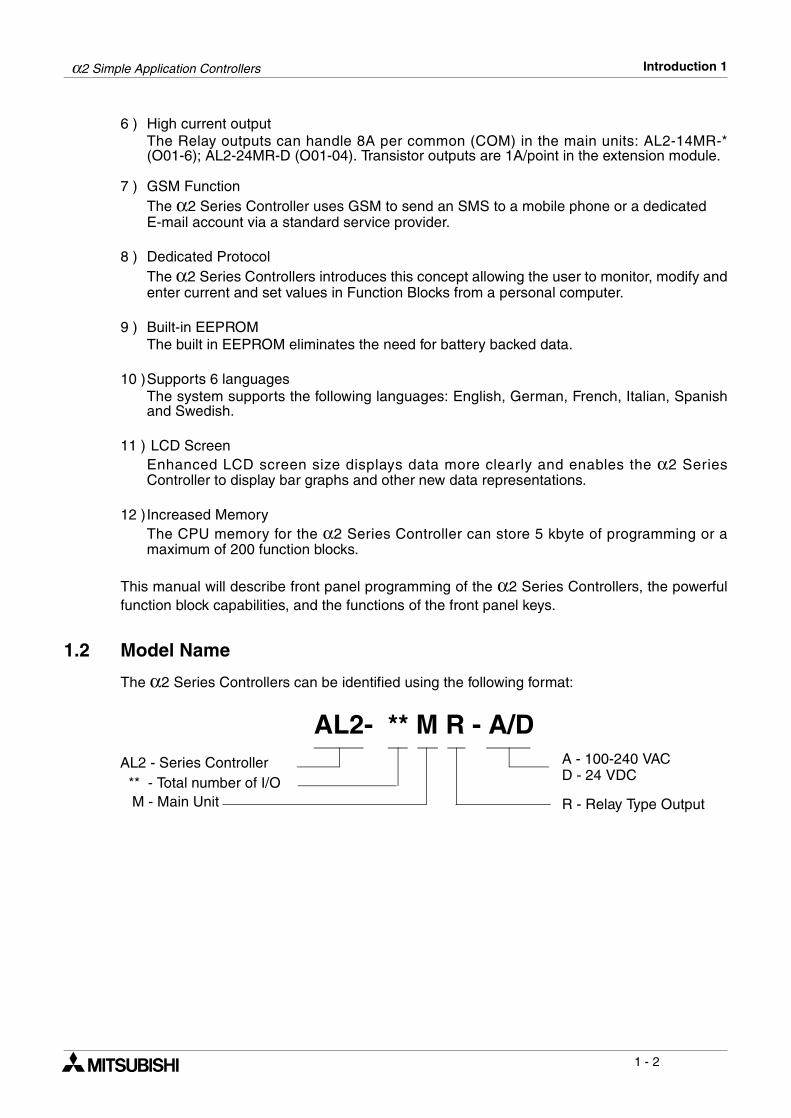
6 ) High current output The Relay outputs can handle 8A per common (COM) in the main units: AL2-14MR-*(O01-6); AL2-24MR-D (O01-04). Transistor outputs are 1A/point in the extension module.
7 ) GSM FunctionThe α2 Series Controller uses GSM to send an SMS to a mobile phone or a dedicated E-mail account via a standard service provider.
8 ) Dedicated ProtocolThe α2 Series Controllers introduces this concept allowing the user to monitor, modify andenter current and set values in Function Blocks from a personal computer.
9 ) Built-in EEPROMThe built in EEPROM eliminates the need for battery backed data.
10 )Supports 6 languagesThe system supports the following languages: English, German, French, Italian, Spanishand Swedish.
11 ) LCD ScreenEnhanced LCD screen size displays data more clearly and enables the α2 SeriesController to display bar graphs and other new data representations.
12 )Increased MemoryThe CPU memory for the α2 Series Controller can store 5 kbyte of programming or amaximum of 200 function blocks.
This manual will describe front panel programming of the α2 Series Controllers, the powerfulfunction block capabilities, and the functions of the front panel keys.
1.2 Model Name
The α2 Series Controllers can be identified using the following format:
AL2- ** M R - A/DAL2 - Series Controller
** - Total number of I/OM - Main Unit
A - 100-240 VACD - 24 VDC
R - Relay Type Output
α2 Simple Application Controllers Function Block Programming 2
2 - 1
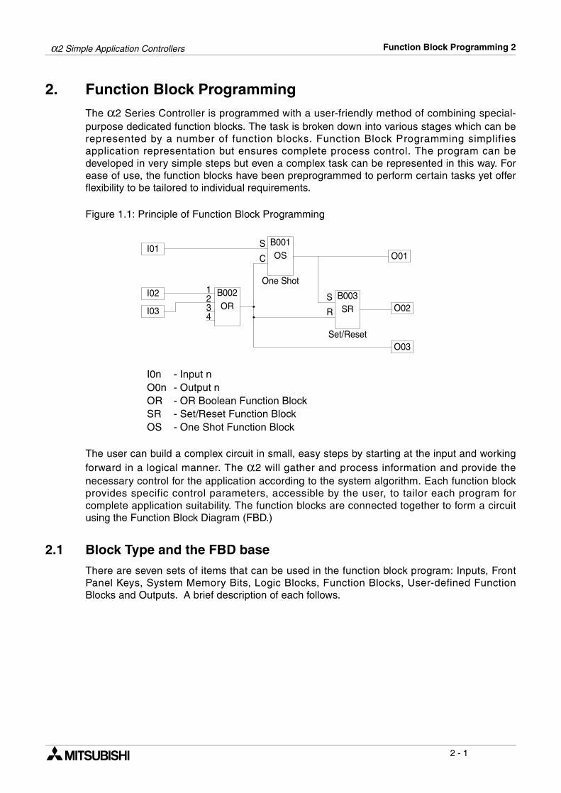
2. Function Block ProgrammingThe α2 Series Controller is programmed with a user-friendly method of combining special-purpose dedicated function blocks. The task is broken down into various stages which can berepresented by a number of function blocks. Function Block Programming simplifiesapplication representation but ensures complete process control. The program can bedeveloped in very simple steps but even a complex task can be represented in this way. Forease of use, the function blocks have been preprogrammed to perform certain tasks yet offerflexibility to be tailored to individual requirements.
Figure 1.1: Principle of Function Block Programming
I0n - Input nO0n - Output nOR - OR Boolean Function BlockSR - Set/Reset Function BlockOS - One Shot Function Block
The user can build a complex circuit in small, easy steps by starting at the input and workingforward in a logical manner. The α2 will gather and process information and provide thenecessary control for the application according to the system algorithm. Each function blockprovides specific control parameters, accessible by the user, to tailor each program forcomplete application suitability. The function blocks are connected together to form a circuitusing the Function Block Diagram (FBD.)
2.1 Block Type and the FBD base
There are seven sets of items that can be used in the function block program: Inputs, FrontPanel Keys, System Memory Bits, Logic Blocks, Function Blocks, User-defined FunctionBlocks and Outputs. A brief description of each follows.
I01
OR
1 B002One Shot
I02
I03234
OSB001S
C
SRB003
Set/Reset
O01
O02
O03
S
R
α2 Simple Application Controllers Function Block Programming 2
2 - 2
2.1.1 Inputs
The α2 Series Controller will accept both digital (On/Off) and analog (mV value based)electrical information through the system Inputs. Please refer to the α2 Hardware Manual forelectrical information, wiring diagrams and input specifications. Depending on the specificcontroller there are either 14 or 24 input version types of the α2 Series Controller. The Inputsare referenced to I01, I02, ..., I15.
Table 2.1: Input type for the α2 Series Controller
2.1.2 Front Panel Keys
The front panel keys can enter data into the program memory, move through menus orprograms, select programming options, or be used as extra inputs when the program isrunning. There are eight keys which are referenced as K01 - K08.
Table 2.2: Front panel keys for the α2 Series Controller
If the front panel keys are used as auxiliary inputs on the FBD, their primary function, as frontpanel display navigators, will be disabled.
Input Input Number Description
Signal I01 - I15 Maximum of 15 Inputs are allocated for use.
AS-i E01 - E04 Maximum of 4 AS-interface inputs are allocated for use.
Analog A01 - A08 Maximum of 8 Analog inputs are allocated for use on input I01 to I08.
Extension EI01 - EI04 Maximum of 4 Extension inputs are allocated for use.
Key Name Key number Key Function
OK K01 Used to enter menu options, confirm data entry, and manually forceinputs ON/OFF in the monitor function.
ESC K02 Used to cancel an operation, move to a higher level screen, or tomove to a new menu.
“+” K03 Used to connect (or “add”) function blocks, increase Direct Set inputvalues or times, or move through programs or menus.
“-” K04 Used to disconnect function blocks, decrease Direct Set values ortimes, or move through programs or menus.
( ) K05 Scroll up through menu options (menus, keys, FB, Inputs, Outputs,etc.)
( ) K06 Scroll down through menu options (menus, keys, FB, Inputs, Outputs,etc.)
( ) K07 Move to the right on the LCD display, FB program, or Jump command
( ) K08 Move to the left on the LCD display, FB program, or Jump command
α2 Simple Application Controllers Function Block Programming 2
2 - 3
2.1.3 System Memory Bits
These System Memory Bits can provide predefined signals - Always On, Always Off, 0.5second On, 0.5 second Off, or provide information about the Real Time Clock time or errorsetc. There are 24 Memory bits that are referenced as M01, M02, ... M24.
Table 2.3: System Bits for the α2 Series Controller
2.1.4 Function Blocks
Programming the α2 Series Controller is based upon the combination of different functionblocks. They process the information received from the previously mentioned inputs andcontrol the system Outputs. They can also provide input signals or information to other functionblocks using word outputs pins. To make programming easier, the Function Blocks have allbeen preprogrammed. However, parameters within each function block dialog box can be setaccording to the intended application. There are 40 Function Blocks available, they aredescribed in detail throughout Chapters 5 and 6.
System Bit Description
M01 Always “ON”.
M02 Always “OFF”.
M03 Alternate - 0.5 seconds “ON”, 0.5 seconds “OFF”.
M04 “ON” when Real Time Clock data error occurs.
M05 “ON” when Summer time schedule is activated.
M06 “ON” when AS-interface communication Error occurs.
M07 “ON” when communication Error caused by AS-interface power failure occurs.
M08 Pulses “ON” when Stop mode turns to Run mode in the α2 Series.
M09 Pulses “OFF” when Stop mode turns to Run mode in the α2 Series.
M10 “ON” during DCF77 decoding
M11 Pulses “ON” when DCF77 finishes decoding without an error
M12 “ON” when CD (DCD) signal is turned ON (receiving CD signal from the modem.)
M13 “ON” when it is possible to access the GSM network.
M14 “ON” when the α2 series controller is accessed via GSM
M15 “ON” when DCF77 finishes decoding with an error
M16 “ON” when external power for the 2DA board is on
M17 “ON” when there is a sensor defect at I01
M18 “ON” when there is a sensor defect at I02
M19 “ON” when there is a sensor defect at I03
M20 “ON” when there is a sensor defect at I04
M21 “ON” when there is a sensor defect at I05
M22 “ON” when there is a sensor defect at I06
M23 “ON” when there is a sensor defect at I07
M24 “ON” when there is a sensor defect at I08

α2 Simple Application Controllers Function Block Programming 2
2 - 4
2.1.5 Outputs
Table 2.4: Outputs for the α2 Series Controller
Note: *1 When both N02 and N03 are ON and hence the back light is “ON” because N03 isgiven the priority.
2.1.6 Function Block Diagram (FBD) base
The Function Block Diagram provides the base for which all programming actions for the α2 is
performed. Both the α2 controller and the AL-PCS/WIN-E software use the FBD base. TheFBD base contains a Title rectangle on the top, Input rectangles on the left and Outputrectangles on the right. The FBD base is also known as FBD wiring area. All the componentsshould be placed only within the FBD base rectangle except for the input and output signalswhich can be placed in the FBD wiring area or in the Input or Output rectangles.
Outputs Description
O01 - 09 Signal output
A01 - 04 AS-interface Output
EO1 - E04 Extension Output
N01ON: Disconnected to AS-interface networkOFF: Connect to AS-interface network
N02*1ON: The back light is “OFF” in LCD.OFF: The back light is controlled by the “Light Time” setting in Menu.
N03*1ON: The back light is “ON” in LCD.OFF: The back light is controlled by the “Light Time” setting in Menu.
N04ON: The user screen is controlled by the setting of “Display Manager” with AL-PCS/
WIN-E.OFF: The user screen is controlled by user program.
α2 Simple Application Controllers Function Block Programming 2
2 - 5
2.2 Programming Methods
2.2.1 Direct Programming
Direct Programming uses the keys on the front panel to create the program and enter anyrequired data values. The method for Direct Programming is explained in Chapter 4 of thismanual.
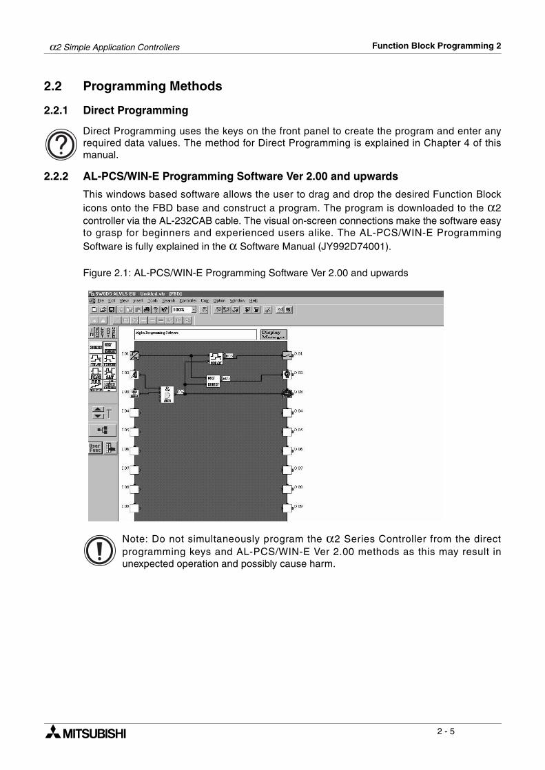
2.2.2 AL-PCS/WIN-E Programming Software Ver 2.00 and upwards
This windows based software allows the user to drag and drop the desired Function Blockicons onto the FBD base and construct a program. The program is downloaded to the α2controller via the AL-232CAB cable. The visual on-screen connections make the software easyto grasp for beginners and experienced users alike. The AL-PCS/WIN-E ProgrammingSoftware is fully explained in the α Software Manual (JY992D74001).
Figure 2.1: AL-PCS/WIN-E Programming Software Ver 2.00 and upwards
Note: Do not simultaneously program the α2 Series Controller from the directprogramming keys and AL-PCS/WIN-E Ver 2.00 methods as this may result inunexpected operation and possibly cause harm.
α2 Simple Application Controllers Function Block Programming 2
2 - 6
MEMO

α2 Simple Application Controllers System Menu 3
3 - 1
3. System Menu
3.1 Menu Options Instructions
There are Systems Menus to help guide the user through the options available in the α2. The
TopMenu has a Run Mode that is accessed while the α2 is in operation or a Stop Mode that is
accessed when the α2 is idle.
The Edit Menu and the Function Block Edit Menu can be accessed when in either ProgEdit orMonitor. These menus can be used to create and/or change programs steps or values.
Use the “OK” key to enter a programming option or to enter data into memory. Set all the data on the screen before using the “OK” key to write the data to the systemmemory. If there are multiple data screens in an option, enter the required data and accepteach screen with the “OK” key.
The “ESC” key will move the screen back to a higher menu option. It will cancel any data inputthat has not been accepted with the “OK” key.
Note: Use the “ESC” key to exit the option to the higher menu; at times, it will be necessary to pressthe “ESC” key a number of times to move through multiple programming layers.
α2 Simple Application Controllers System Menu 3
3 - 2
3.2 The Stop Mode
3.2.1 Top Menu
When the α2 is first turned On, the Input/Output Image Table will appear. Press the “OK” and“ESC” keys simultaneously to move to the TopMenu. (If the TopMenu cannot be accessed the Menu Key has been set to “Not Use”),
• Run:Places the controller in Run mode.
• Setup TS:Provides a simple method to edit Time Switches from the Top Menu (only selectable if a TSm function block has been chosen.)
• ProgEdit:Allows program editing/creation on the display using the front panel keys. The current memory will be overwritten as changes are made to the program. Programs can be saved on an AL2-EEPROM-2 memory cassette or in the AL-PCS/WIN-E software Version 2.0 or above.
• ClockSet:Set the Real Time Clock or input a daily clock adjustment. The RadioClock function is also available here.
• LANGUAGE:Choose from 6 onscreen languages: English, German, French, Italian, Spanish, or Swedish.
• Others...
Figure 3.1: TopMenu in Stop Mode operation
•
Run Mode
LANGUAGE
OKESC
1 0 : 1 9 F r iI : R u n
C l o c k S e t
T o pMe n u
S e t u p T S
P r o g E d i t
L ANGUAGE
S e t u p
R u n / S t o p
OK o r ESC
S t o p →R u n
N o D a t a
E n g l i s hGe r ma nF r e n c hI t a l i a nS p a n i s hSw d i s h
ST
O t h e r s
e
• 2 • • 5 • • 9• 1 • • •
•5
O : 1 • • 4 • • 8•E : 1 • • 4A : • 2 3
E I : • • 41
EO : 2 3 ••
12
34
910
α2 Simple Application Controllers System Menu 3
3 - 3
Figure 3.2: ClockSet Menu in Stop Mode Operation
l o c k s e t
C o r r c t
C l o c k s e
S t o p A c t
OK o r ESC
R a d i o C l o
910
Cl o c k s e tC
td d / mm / y y y y2 9 / 6 / 2 0 0 3
7 : 5 9 Su n
C o r r e c t0 . 0 0 s / d
e
c k R a d i o C l o c kR a d i o C l o c k
R a d i o C l o c kN o t U s eDCF 7 7
R a d i o C l o c kR a d i o C l o c kI n p u tT i me D i f f e r
R a d i o C l o c kI n p u t
I 0 1
R a d i o C l o c kR a d i o C l o c kI n p u tT i me D i f f e r
R a d i o C l o c k
0 . 0T i me D i f f e r
h r s
R a d i o C l o c kI n p u tT i me D i f f e rMa n u a l
Ma n u a l.
α2 Simple Application Controllers System Menu 3
3 - 4
3.2.2 The “Others...
• Version:Displays CPU Version of the α2 Series Controller.
• Scan Time:Monitor the Current, Maximum, or Minimum program scan times. Upon controller resetcurrent, Maximum and Minimum values for scan times are reset to 0.
• Password:Restrict entry to the ProgEdit and Monitor mode with a four digit password.
• DispPass:Set up to three Passwords for Display function blocks.
• Menu Key:Two settings are possible, “Not Use” or “OK + ESC”. “Not Use” is designed so thatunauthorized people cannot access the α2 Top Menu in Run mode. If the “OK + ESC” keysetting is selected, simultaneously depress the “OK” and the “ESC” keys to access the TopMenu.
• Summertime:Choose the preferred daylight savings time: Cancel, Manual On, Date Type, UK type, UStype, or EU type.
• Serial Com:Choose the type of communication to be used for the right hand side serial communicationport - Not Use, Modem, GSM or Other Com.
• Light Time:Set the backlight off delay time.
• Analog In:Indicates the current modes (Normal, TC pr PT100) of the Analog inputs and the menuitem for changing the temperature scale (°C or °F) that the controller displays. Alsocontains the menu items for calibration and offset adjust.
• ProgClear:Completely clears the system memory including Password protected programs. Only theactive memory is cleared, i.e. if a memory cassette is installed, the memory cassetteprogram will be erased but the controller memory will be retained.
• ProgTran. (only appears if a cassette is installed):Verify, Cassette " (the cassette writes to the α2), Cassette #(the cassette reads fromthe α2), and ProtectSW are the options available.
α2 Simple Application Controllers System Menu 3
3 - 5
Figure 3.2: Others Menu in Stop Mode operation
O t h e r s . . .
V e r s i o n
S c a n T i m
V e r s i o n
V e r * . * *
S c a n T i meMo n i t o rR e s e t
S c a n T i meC u r . 0msMa x .M i n
1 2ms0ms
S c a n T i meMo n i t o rR e s e t
R e s e tS c a n T i me
OK o r ESC
S e t u pP a s s w o r d
D i s p P a s s
P a s s w o r d
D i s p P a s sL e v e l 1L e v e l 2L e v e l 3
D i s p P a s sL e v e l 1
S e t u p
Me n u K e yMe n u K e y
N oON+
U s eESCK e y
S umme r T i meS umme r T i me
C a n c e lMa n u a l OnD a t a T y p eUK T y p eUS T y p eEU T y p e
S umme r T i me3 1 / 0 3
~ 3 0 / 1 0+ 6 0m i n
34
e
S e r i a l C om
L i g h t T i me
P r o g c l e a rP r o g r am
S e t u pL i g h t T i me
2m
OK o r ESCP r o g T r a n
56
A n a l o g I n 1112
C l e a r

α2 Simple Application Controllers System Menu 3
3 - 6
Figure 3.3: Serial Com in Stop Mode operation
Figure 3.4: Communication Format in Stop Mode Operation* Comformat
Datalength (bit) 8, 7
Parity None, Odd, Even
Stopbit (bit) 1, 2
Baudrate (bps) 300, 600, 1200, 2400, 4800, 9600, 19200
GSM
S e r i a l C omN o t U s eMo d em
Mo d em I n i tC omma n dD e l y T i me
Mo d em I n i tC omma n d
GSMC om f o r ma tGSM I n i t
P NC o d eS e t SMSGSMS t a t u s
C om f o r ma t *S t a t i o n N oL i n k B l o c k
O t h e r C om O t h e r C omS t a t i o n N o
N o . 0
O t h e r C omL i n k B l o c k
0 .
C om f o r ma t *S t a t i o n N oL i n k B l o c k
O t h e r C om
O t h e r C om
GS R emo t e
Mo d em I n i t 0 1C omma n d[ ]y z { | } ! " # $
Mo d em I n i t
0 s
a
D e l y T i meaD e l y T i mea
MI
56
78
α2 Simple Application Controllers System Menu 3
3 - 7
Figure 3.5: GSM Menu in Stop Mode operation
Figure 3.6: Communication Format in Stop Mode operation* Comformat
Datalength (bit) 8, 7
Parity None, Odd, Even
Stopbit (bit) 1, 2
Baudrate (bps) 300, 600, 1200, 2400, 4800, 9600, 19200
GSM
C om f o r ma t *
GSM I n i t
S e t SMS
GSMS t a t u s
GS R emo t e
P NC o d e
GSM I n i tC ommn dD e l a y T i me
GS R emo t eF o r b i tP e r m i t
P I NC o d eS e t u p
[ * * * * ]
S e t SMSSMSC 1SMSC 2DA 1DA 2DA 3VP
GSMS t a t u sS t a t u sCMEE r r o rCMSE r r o rS i g S e i n g
MM
I
78
α2 Simple Application Controllers System Menu 3
3 - 8
Figure *.*: Analog Inputs Setup Menu.
n a l o g nI
I 0 2 : C
I 0 3 : P 1 0 0
A0 1I
I 0 1Mo d e
T
1112
I 0 1N o r ma lTCP T 1 0 0
T
T emp . c a lS e
I 0 2Mo d e
I 0 2
C a l i b r a t eO f f s e F i n et
C a l i b r a t e- 5 0 ° C4 5 0 ° C
I 0 3Mo d e
I 0 3
C a l i b r a t eO f f s e F i n et
C a l i b r a t e- 5 0 ° C2 0 0 ° C
I 0 3Mo d e
I 0 3
C a l i b r a t eO f f s e F i n et
0 . 0 ° CO f f s e F i n et
A n aT empC e l c i u sF a h r e h e i tn
l o g I n. c a lS e
α2 Simple Application Controllers System Menu 3
3 - 9
Add FB O 01
(OK, ESC, +, -, , , , )
01
In
01
Connect EO 04
Adding Function Blocks
(+) or (-) Skips tothe next topic
*1
*2
*3
Function Block SpecificChanges Function Block NumberDeletes Function Block fromFBD
E d i t Me n u
P r o g S i z e
N e wF B
E x i t
Mn emo n i c
D e l a y e d A
F BS e l e c tAND
D e l e t e F B
F BP a r ameS e t
t e ru p F B *1
C h a n g e N *2o*3
B l o c k 0 F B
Memo r y 0%
J umpM I OK E A NE I EOB
F BS e l e c tAND
D e l a y e d A
M0 1 -
J ump
Pr og r amSc r een
L
L
12
α2 Simple Application Controllers System Menu 3
3 - 10
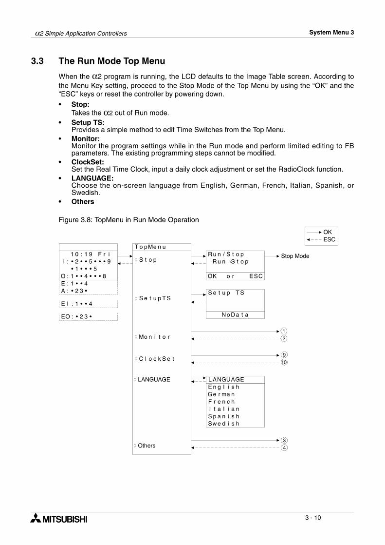
3.3 The Run Mode Top Menu
When the α2 program is running, the LCD defaults to the Image Table screen. According tothe Menu Key setting, proceed to the Stop Mode of the Top Menu by using the “OK” and the“ESC” keys or reset the controller by powering down.
• Stop:Takes the α2 out of Run mode.
• Setup TS:Provides a simple method to edit Time Switches from the Top Menu.
• Monitor:Monitor the program settings while in the Run mode and perform limited editing to FBparameters. The existing programming steps cannot be modified.
• ClockSet:Set the Real Time Clock, input a daily clock adjustment or set the RadioClock function.
• LANGUAGE:Choose the on-screen language from English, German, French, Italian, Spanish, orSwedish.
• Others
Figure 3.8: TopMenu in Run Mode Operation
Stop Mode
LANGUAGE
Others
OKESC
C l o c k S e t
T o pMe n u
S e t u p T S
Mo n i t o r
L ANGUAGE
S e t u p
R u n / S t o p
OK o r ESC
S t o p→R u n
N o D a t a
E n g l i s hGe r ma nF r e n c hI t a l i a nS p a n i s hSw d i s h
S t o p
T S
e
•
1 0 : 1 9 F r iI : • 2 • • 5 • • 9
• 1 • • ••5
O : 1 • • 4 • • 8•E : 1 • • 4A : • 2 3
E I : • • 41
EO : 2 3 ••
12
34
910
α2 Simple Application Controllers System Menu 3
3 - 11
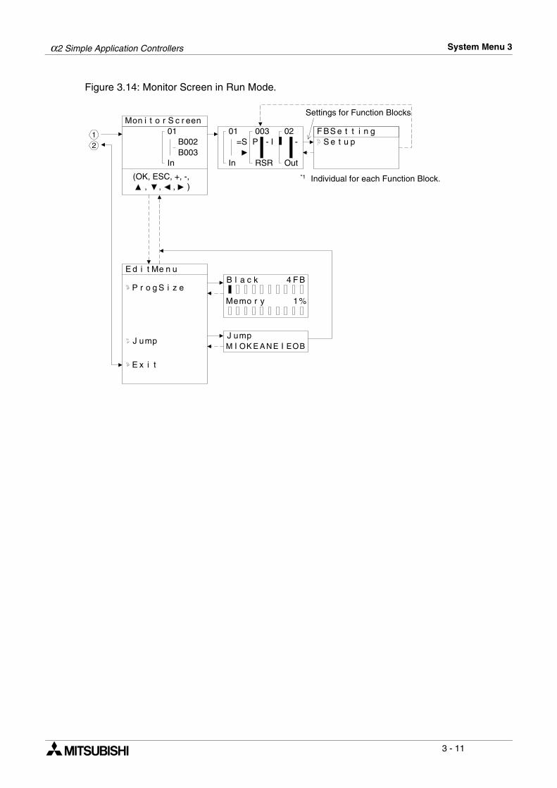
Figure 3.14: Monitor Screen in Run Mode.
Individual for each Function Block.*1(OK, ESC, +, -, , , , )
01
Settings for Function Blocks
E d i t Me n u
P r o g S i z e
E x i t
F BS e t t i nS e t
B l a c k 4 F B
Memo r y 1%
J umpM I OK E A NE I EOB
In
B002B003
01
In
=S003
RSR
P - I02
Out
-g
u p
J ump
Mon i t o r S c r een
12
α2 Simple Application Controllers System Menu 3
3 - 12
Figure 3.9: Others Menu in Run Mode operation
O t h e r s . . .
V e r s i o n
S c a n T i me
V e r s i o n
V e r * . * *
S c a n T i meMo n i t o rR e s e t
S c a n T i meC u r . 0msMa x .M i n
1 2ms0ms
S c a n T i meMo n i t o rR e s e t
R e s e tS c a n T i me
OK o r ESC
S e t u pP a s s w o r d
D i s p P a s s
P a s s w o r d
D i s p P a s sL e v e l 1L e v e l 2L e v e l 3
D i s p P a s sL e v e l 1
S e t u p
Me n u K e y
S umme r T i meS umme r T i me
C a n c e lMa n u a l OnD a t a T y p eUK T y p eUS T y p eEU T y p e
S umme r T i me3 1 / 0 3
~ 3 0 / 1 0+ 6 0m i n
Me n u K e yN oON+
U s eESCK e y
34
S e r i a l C om
L i g h t T i meS e t u p
L i g h t T i me2m
P r o g T r a n
56
A n a l o g I nA n a
I 0 7I 0 8
l o g I n A n aT empC e l c i u sF a h r e h e i tn
l o g I n. c a lS e
T emp . c a lS e
I 0 5I 0 6
I 0 3I 0 4
I 0 1I 0 2
α2 Simple Application Controllers System Menu 3
3 - 13
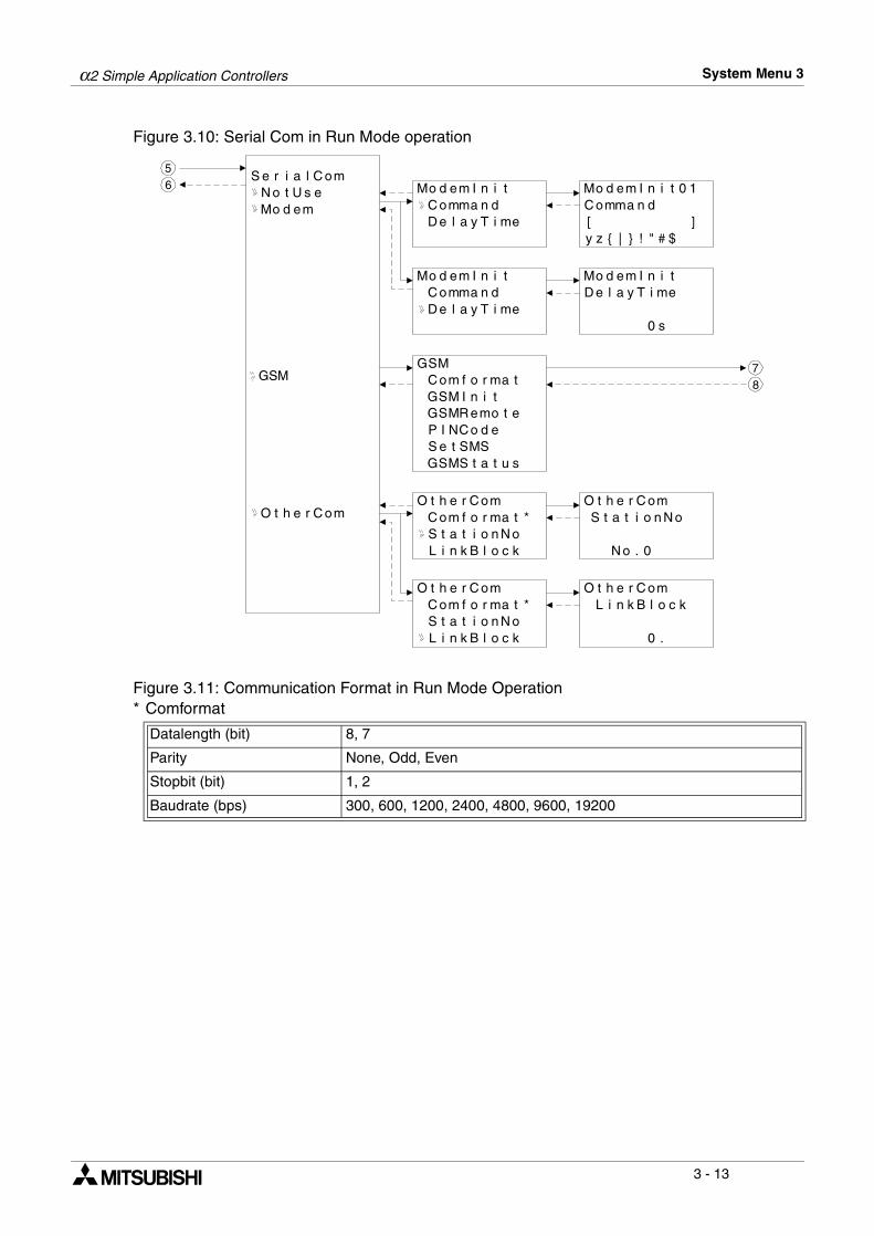
Figure 3.10: Serial Com in Run Mode operation
Figure 3.11: Communication Format in Run Mode Operation* Comformat
Datalength (bit) 8, 7
Parity None, Odd, Even
Stopbit (bit) 1, 2
Baudrate (bps) 300, 600, 1200, 2400, 4800, 9600, 19200
GSM
S e r i a l C omN o t U s eMo d em
Mo d em I n i tC omma n d
T i me
Mo d em I n i tC omma n d
GSMC om f o r ma tGSM I n i t
P NC o d eS e t SMSGSMS t a t u s
C om f o r ma t *S t a t i o n N oL i n k B l o c k
O t h e r C om O t h e r C omS t a t i o n N o
N o . 0
O t h e r C omL i n k B l o c k
0 .
C om f o r ma t *S t a t i o n N oL i n k B l o c k
O t h e r C om
O t h e r C om
GS R emo t e
Mo d em I n i t 0 1C omma n d[ ]y z { | } ! " # $
Mo d em I n i t
0 s
D e l a y
T i meD e l a yT i meD e l a y
MI
56
78

α2 Simple Application Controllers System Menu 3
3 - 14
Figure 3.12: GSM Menu in Run Mode operation
Figure 3.13: Communication Format in Run Mode operation* Comformat
Datalength (bit) 8, 7
Parity None, Odd, Even
Stopbit (bit) 1, 2
Baudrate (bps) 9600, 19200
GSM
C om f o r ma t *
GSM I n i t
S e t SMS
GSMS t a t u s
GS R emo t e
P NC o d e
GSM I n i tC om a n dD e l a y T i me
GSR emo t eF o r b i tP e r m i t
P I NC o d eS e t u p
[ * * * * ]
S e t SMSSMSC 1SMSC 2DA 1DA 2DA 3VP
GSMS t a t u sS t a t u sCMEE r r o rCMSE r r o rS i g S t i n g
M
m
I
r
78
α2 Simple Application Controllers System Menu 3
3 - 15
3.4 The Edit Menu
The Edit Menu can be entered when the α2 is in the ProgEdit or Monitor main programmingscreen. If entering options or connecting FBs, these procedures have to be finished orcanceled before the Edit Menu can be entered. Press the “ESC” key at any place in the mainprogramming screen to enter the Edit Menu.
• ProgSize:Shows the numbers of FBs used and percentage of program memory used.
• Jump:Leads to a screen that shows available places to go in the program. “M” - system bits; “I” -system Inputs; “O” - System Outputs; “K” - Keys (1-8); “E” - ASi Inputs; “A” - ASi Outputs;“N” - Control bits; “EI” - External Board inputs; “EO” - External Board outputs; and “B” -Function Blocks existing in the program. Choose the desired block with the arrow keysand press the “OK” key to jump to that spot in the program.
• New FB:Create a new Function Block from one of the available FBs.
• Exit: Exits to the Top Menu.• Mnemonic:
Gives a mnemonic display of the current programming rung. Enter the programming modeby pressing the “OK” key or return to the Edit Menu using the “ESC” key. (Not available inMonitor Mode).
3.5 The Function Block Edit Menu
The Function Block Edit Menu can be entered only while in the ProgEdit or Monitor mode.Move to the Function Block to edit and press the “OK” key when the Function Block number isflashing.
• Setup FB:Set variables in the Function Blocks for your application. See Chapter 6 for more details oneach Function Block’s Options. The logic functions in Chapter 5 do not have SetupOptions.
• Change No: Change the Function Block Number• Delete FB: Delete Selected Function Block
α2 Simple Application Controllers System Menu 3
3 - 16
3.6 Option Screen Setup
Various options have been provided for ease of use or for safety purposes. Please set as yourneeds require. All of the options in this section can be accessed from either the Run or theStop Menu.
3.6.1 ProgEdit
Refer to chapter 4, Direct programming, for detailed instructions on programming the α2Series Controller.
3.6.2 Change the Language Setting
1 ) Turn the α2 On.2 ) Press the “OK” and “ESC” buttons simultaneously to go to the TopMenu or reset the
controller.3 ) Scroll to the “LANGUAGE” option and press the “OK” key. The spelling for “LANGUAGE”
does not change.4 ) Scroll to the desired language and press the “OK” key. The languages available are
English, German, French, Italian, Spanish, and Swedish.5 ) Use the “ESC” key to exit to the Topmenu.
3.6.3 ClockSET
To set the Clock:1 ) From the TopMenu, scroll to “ClockSet” and press the “OK” key.2 ) From the options that appear, choose “ClockSet” and press the “OK” key. 3 ) Use the arrow keys to move to an area that needs to be changed.4 ) Adjust with the “+” or “-” keys.5 ) Repeat steps 3-4 until ALL changes have been completed.6 ) Press the “OK” key to accept all the changes or the “ESC” to discards the changes.7 ) Press the “ESC” key to return to the Top Menu.
To set the daily correction: 1 ) From the TopMenu, scroll to “ClockSet” and press the “OK” key.2 ) From the options that appear, choose “Correct” and press the “OK” key. 3 ) Set the daily correction time with the “+” or “-” keys.4 ) Press the “OK” key to accept the value and press the “ESC” key to return to the Top Menu.
Note:The date setting can be displayed as yyyy/mm/dd, dd/mm/yyyy, or mm/dd/yyyy bymanipulating the “+” and “-” keys. The day of the week will update automatically as the date ischanged.
α2 Simple Application Controllers System Menu 3
3 - 17
3.6.4 RadioClock - DCF77 Decoding
The RadioClock function enables the reception of time information broadcasted by radio signalon 77.5 kHz from Frankfurt Germany. Special hardware is required for this feature. Refer to theAlpha 2 Hardware Manual for more information. After configuring the hardware, follow thesteps below to set the controller for DCF77 decoding:1 ) From the TopMenu, scroll to “ClockSet” and press the “OK” key.2 ) From the options that appear, scroll to “RadioClock” and press the “OK” key.3 ) Only one option appears if RadioClock has not been activated. Scroll to “RadioClock”
and press the “OK” key. 4 ) From the options that appear, scroll to “DCF77” and press the “OK” key. At this point, if the
controller cannot detect a signal the message “No Signal!” will flash on the headline.5 ) To select the correct analog input that carries the DCF77 time signal, scroll to “Input No.”
and press the “OK” key. Initially “Input No.” will not be visible, it only appears as an optionafter the RadioClock function has been enabled.
6 ) Select the Analog Input number from I01 to I08 with the +,- keys and the “OK” key. 7 ) If necessary, adjust for the timezone difference between Frankfurt, Germany and the place
of installation. This amount is added to (subtracted from) the received time. To do this,scroll to “TimeDiffer” and press the “OK” key.
8 ) Select the timezone difference in half hour increments using the +,- keys. Press “OK” toenter the timezone difference.
9 ) It is possible to manually start and stop the decoding of the time information. Scroll to“Manual” and press the “OK” key. Either “Start Act.” or “Stop Act.” will be displayeddepending on the state of the controller at the time.
Note:The “Input No.”, “TimeDiffer” and “Manual” selections will only be displayed when“DCF77” has been enabled from the “RadioClock” menu.
The error message “No Signal!” will flash on the headline if the controller does not receive theDCF77 signal when the input is setup for the RadioClock function. If there should be a signal inthe installation area, check the setup and hardware for faults.
When in STOP mode and “Start Act.” is used to manually start DCF77 decoding, the user mustcheck the state of M10 (decoding active flag) 30 minutes after starting the decoding. If M10 isoff, DCF77 decoding finished without error. If M10 is still ON, there is a problem with either thewiring or the availability of the signal in the location of use (e.g. antenna problems). The usershould check both possible causes.
α2 Simple Application Controllers System Menu 3
3 - 18
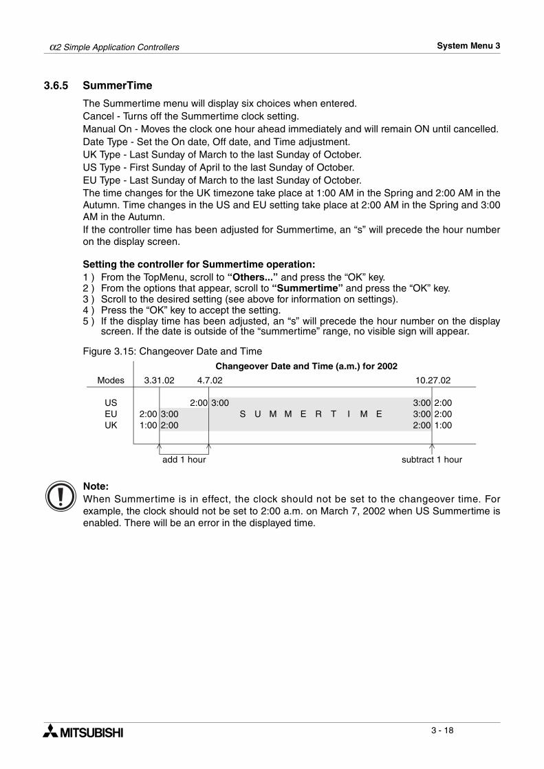
3.6.5 SummerTime
The Summertime menu will display six choices when entered.Cancel - Turns off the Summertime clock setting.Manual On - Moves the clock one hour ahead immediately and will remain ON until cancelled.Date Type - Set the On date, Off date, and Time adjustment.UK Type - Last Sunday of March to the last Sunday of October.US Type - First Sunday of April to the last Sunday of October.EU Type - Last Sunday of March to the last Sunday of October.The time changes for the UK timezone take place at 1:00 AM in the Spring and 2:00 AM in theAutumn. Time changes in the US and EU setting take place at 2:00 AM in the Spring and 3:00AM in the Autumn. If the controller time has been adjusted for Summertime, an “s” will precede the hour numberon the display screen.
Setting the controller for Summertime operation:1 ) From the TopMenu, scroll to “Others...” and press the “OK” key. 2 ) From the options that appear, scroll to “Summertime” and press the “OK” key.3 ) Scroll to the desired setting (see above for information on settings). 4 ) Press the “OK” key to accept the setting.5 ) If the display time has been adjusted, an “s” will precede the hour number on the display
screen. If the date is outside of the “summertime” range, no visible sign will appear.
Figure 3.15: Changeover Date and Time
Note:When Summertime is in effect, the clock should not be set to the changeover time. Forexample, the clock should not be set to 2:00 a.m. on March 7, 2002 when US Summertime isenabled. There will be an error in the displayed time.
Changeover Date and Time (a.m.) for 2002
Modes 3.31.02 4.7.02 10.27.02
US 2:00 3:00 3:00 2:00EU 2:00 3:00 S U M M E R T I M E 3:00 2:00UK 1:00 2:00 2:00 1:00
add 1 hour subtract 1 hour
α2 Simple Application Controllers System Menu 3
3 - 19
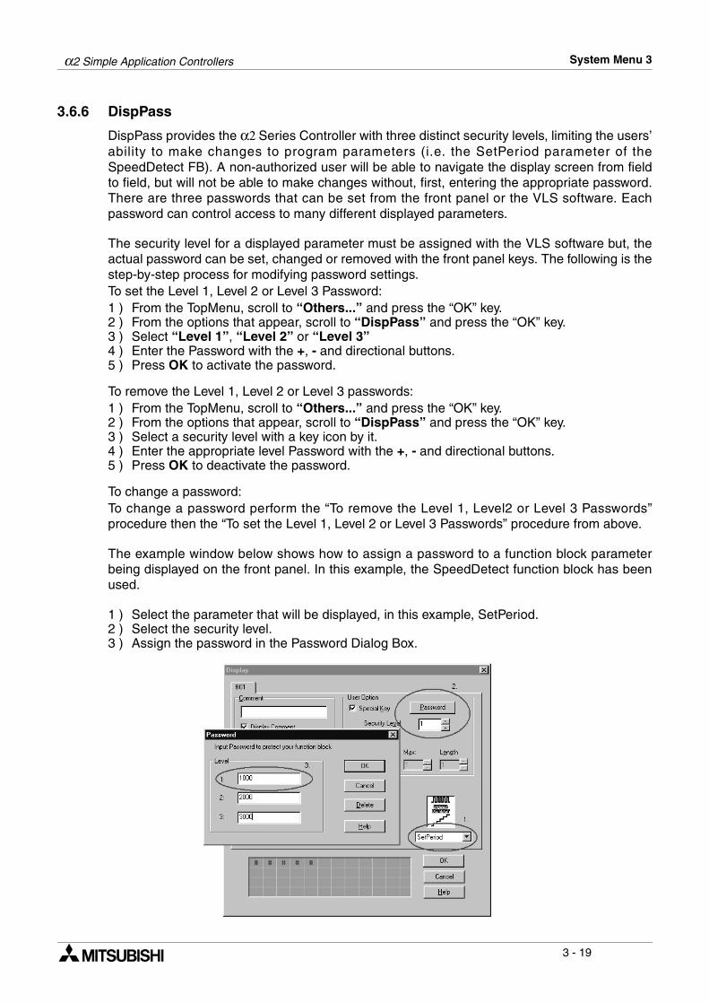
3.6.6 DispPass
DispPass provides the α2 Series Controller with three distinct security levels, limiting the users’ability to make changes to program parameters (i.e. the SetPeriod parameter of theSpeedDetect FB). A non-authorized user will be able to navigate the display screen from fieldto field, but will not be able to make changes without, first, entering the appropriate password.There are three passwords that can be set from the front panel or the VLS software. Eachpassword can control access to many different displayed parameters.
The security level for a displayed parameter must be assigned with the VLS software but, theactual password can be set, changed or removed with the front panel keys. The following is thestep-by-step process for modifying password settings.To set the Level 1, Level 2 or Level 3 Password:1 ) From the TopMenu, scroll to “Others...” and press the “OK” key.2 ) From the options that appear, scroll to “DispPass” and press the “OK” key.3 ) Select “Level 1”, “Level 2” or “Level 3”4 ) Enter the Password with the +, - and directional buttons.5 ) Press OK to activate the password.
To remove the Level 1, Level 2 or Level 3 passwords:1 ) From the TopMenu, scroll to “Others...” and press the “OK” key.2 ) From the options that appear, scroll to “DispPass” and press the “OK” key.3 ) Select a security level with a key icon by it. 4 ) Enter the appropriate level Password with the +, - and directional buttons. 5 ) Press OK to deactivate the password.
To change a password:To change a password perform the “To remove the Level 1, Level2 or Level 3 Passwords”procedure then the “To set the Level 1, Level 2 or Level 3 Passwords” procedure from above.
The example window below shows how to assign a password to a function block parameterbeing displayed on the front panel. In this example, the SpeedDetect function block has beenused.
1 ) Select the parameter that will be displayed, in this example, SetPeriod.2 ) Select the security level.3 ) Assign the password in the Password Dialog Box.
α2 Simple Application Controllers System Menu 3
3 - 20
3.6.7 Password
The password consists of four digits and will prohibit entry into the ProgEdit, Monitor, DispPass and Serial Com modes only. All other menu options can be accessed when a Passwordis used.
To Enter a Password:1 ) Select “Others...” Menu Option.2 ) Select “Password” from the “Others...” Menu Options3 ) Use the “+” and “-” keys to enter the desired password.4 ) Press the “OK” key to accept and activate the password.5 ) A key symbol will now be displayed at the top of the α2 display.
To Cancel a Password:1 ) Select the “Others...” Menu Option.2 ) Select “Password” from the “Other” Menu Options. “Cancel Password” should appear on
the top of the screen. 3 ) Use the “+” and “-” keys to enter the current password.4 ) Press the “OK” key to accept and deactivate the password.5 ) The key symbol will be removed from the α2 display.
Note 1: A Password protected program in an AL2-EEPROM-2 Cassette can be run from andbe downloaded into the main body of the controller. Note 2: A controller containing a Password protected program can accept or transferprograms to an AL2-EEPROM-2.Note 3: The Password can also be set/deleted from the AL-PCS/WIN-E software or deleted bythe “PROGCLEAR” command.
3.6.8 Serial Com
The modem function capability of the α2 allows remote monitoring via a PC and programupload/download. The communication must take place using Visual Logic Software (VLS) andthe communication must be initiated accordingly. (The modem connected to the α2 isinitialized upon the α2 start-up. Dialing options from a command or specific conditions are notavailable).
Command - Enter the AT command for the modem to be connected to the controller.Reference the Modem User manual for details on that unit’s AT command. Choose the firstletter or symbol by using the ( ) and ( ) arrows. When the symbol is showing in the commandline, use the ( ) and ( ) arrows to move to adjoining spaces. Enter up to 64 letters/symbolsand accept the whole string with the “OK” key when finished inputting the data. (There is noneed to accept each letter with the “OK” key).
Delay - The Delay function sets the length of time the α2 will wait after entering the Run modebefore turning on the modem. Choose a value of 0 - 10 seconds using the “+” or “-” keys. Themodem connected to the Personal Computer with VLS software must be set ON prior to theα2 modem turning on.
The GSM function allows a SMS (Short Message Service) message to be sent to either amobile telephone or an email account. The SMS provides the remote user with the identicalLCD screen’s data. Refer to the α2 Communication Manual for detailed explanationconcerning GSM parameters.
The OtherCom function provides the user with an on-line programming feature usingdedicated protocol. Refer to the α2 Communication Manual for detailed explanationconcerning Dedicated Protocol parameters.
α2 Simple Application Controllers System Menu 3
3 - 21
3.6.9 Memory cassette
The Memory Cassette EEPROM is the active memory whenever it is properly installed inthe αααα2 controller. The controller must be powered down before installing/removing thememory cassette or an error will occur.
To Verify a Program:
1 ) Install the AL2-EEPROM-2. Refer to the AL2-EEPROM-2 instruction manual for help.2 ) Select “Others...” in the Top Menu.3 ) Select “ProgTran.”4 ) Select “Verify”.5 ) Choose “OK” to proceed or “ESC” to exit.6 ) If the program is successfully verified, the work “Completed” will blink on screen.7 ) If the programs are not the same, the words “Verify Error” will blink onscreen.
To Transfer a Program from the Cassette to the αααα2:
1 ) Install the AL2-EEPROM-2. Refer to the AL2-EEPROM-2 instruction manual for help.2 ) Select “Others...” in the Top Menu.3 ) Select “ProgTran.”4 ) Select “Cassette→”.5 ) Choose “OK” to proceed or “ESC” to exit.6 ) When the program is successfully transferred, “Completed” will blink on the display.
To Transfer a Program from the αααα2 to the Cassette:
1 ) Install the AL2-EEPROM-2. Refer to the AL2-EEPROM-2 instruction manual.2 ) Select “Others...” in the Top Menu.3 ) Select “ProgTran.”4 ) Select “Cassette←”.5 ) Choose “OK” to proceed or “ESC” to exit.6 ) When the program is successfully transferred, “Completed” will blink on the display.
To apply the “ProtectSW” Feature:The “ProtectSW” will write protect the program in the memory cassette. The program cannotbe edited nor erased when the feature is ON.
1 ) Install the AL2-EEPROM-2 per the instruction manual.2 ) Select “Others...” in the Top Menu.3 ) Select “ProgTran.”4 ) Select “ProtectSW”.5 ) Choose “On“ to activate the feature.
To Remove the “ProtectSW” Feature:
1 ) Install the AL2-EEPROM-2. Refer to the AL2-EEPROM-2 instruction manual.2 ) Select “Others...” in the Top Menu.3 ) Select “ProgTran.”4 ) Select “ProtectSW”.5 ) Choose “Off“ to de-activate the feature.
α2 Simple Application Controllers System Menu 3
3 - 22
3.6.10 Analog Inputs
The Analog Inputs can be configured for three different modes: Normal, TC and PT100.Normal mode is used for ordinary analog signals. TC and PT100 modes should be used withthe AL2-2TC-ADP and AL2-2PT-ADP modules respectively. For more information on thesemodules, refer to the Alpha Hardware Manuals and the individual installation manuals. Thefollowing changes should be made in the Stop mode. Only the “OffsetFine” adjust works inboth RUN and STOP modes.To Set/Change the modes of the Analog Inputs (Stop Mode only):
1 ) Select “Others...” from the TopMenu while in Stop Mode. 2 ) Select “Analog In.”3 ) Choose the appropriate input and press OK.4 ) “Mode” will be the only option displayed if the analog input was previously set on “Normal.”
Select “Mode” by pressing the OK button. Then, select the appropriate mode setting.“Calibrate” and “OffsetFine” should appear on the Analog Input settings menu.
Offset Calibration of the PT 100 and TC inputs (Stop Mode only):
1 ) Before beginning, follow the instructions on preparing the hardware for calibration in the α2Hardware Manual, Chapter 12 for the PT100 input and Chapter 13 for the TC input.
2 ) Select “Others...” from the TopMenu while in Stop Mode. 3 ) After setting the mode to TC or PT100 (See the method for changing modes in the previ-
ous description.), select “Calibrate” from the Analog input settings menu.4 ) Select -50°C and press OK. This completes the offset calibration procedure.
Gain Calibration of the PT100 and TC inputs (Stop Mode only):
1 ) Before beginning, follow the instructions on preparing the hardware for gain calibration inthe α2 Hardware Manual, Chapter 12 for the PT100 input and Chapter 13 for the TC input.
2 ) Select “Others...” from the TopMenu while in Stop Mode. 3 ) After setting the mode to TC or PT100 (See the method for changing modes in the previ-
ous description.), select “Calibrate” from the Analog input settings menu.4 ) Select 200°C for the PT100 input or 450°C for the TC input and press OK. This completes
the gain calibration procedure.
Fine Adjust for the Offset:
1 ) Select “Others...” from the TopMenu either in Stop or Run Mode. 2 ) After setting the mode to TC or PT100, select “OffsetFine” from the Analog input settings
menu.3 ) “OffsetFine” can be adjusted while in Run or Stop Mode. Use the + and - buttons to select
the appropriate offset value.
Note:The fine adjust step size for the PT100 mode is 0.5°C and 1.0°C for the TC mode. TheFahrenheit step sizes are 0.9°F and 1.8°F respectively.
α2 Simple Application Controllers System Menu 3
3 - 23
To change the temperature scale setting (Stop Mode only):
1 ) Select “Others...” from the TopMenu while in Stop Mode.2 ) Select “Analog In.”3 ) Select “TempScale.”4 ) Select “Celsius” or “Fahrenheit.”
Note:In Run Mode, the temperature scale can be checked but cannot be changed.
Note:System flags, M17 through M24, correspond to the 8 possible temperature input channels, I01through I08. When the analog input is configured for TC or PT100 input, these system flags willdetect a defect in the ADP module’s operation. An input voltage of more than 11 volts will setthe corresponding flag and indicates a sensor problem. An input voltage of 0 volts will also setthe corresponding flag, but indicates a power failure at the ADP module.
3.7 LCD Displays
There are a number of types of data and/or information that can be displayed on the LCDdisplay besides the menus listed previously.
3.7.1 Image Table
The first LCD display to appear is the Input/Output image table and the Real Time Clock. Theclock shows the current time as set by the user. The Summertime mode is shown by an “s”preceding the time if activated.
3.7.2 LCD Function
Display up to 12 different letters or characters on each of four lines. Options include characterstrings (design your own message), function block data, or analog data.

α2 Simple Application Controllers System Menu 3
3 - 24
3.8 Block Items
Each block item contains an individual diagram that shows the block number, available numberof input pins, the output pin if applicable, and the block mnemonic. Connections betweenblocks can be viewed at the pin locations when connected blocks are shown individually on theLCD.
3.8.1 Input Blocks
The Input Blocks consist of System Inputs (I01 - I15), Key Inputs (K01-K08), and System Bits(M01-M14). The input number is shown in the top right hand corner, the type of input in thelower right hand corner, and the output pin is shown on the far right of the block. Input Blocksprovide information to the Function Blocks or Outputs.
3.8.2 Function Blocks
The individual Function Blocks are described in detail in Chapters 5 and 6. Function Blockscan have 0 to 4 input pins shown on the left of the diagram and an output shown on the farright. Some function blocks have data that can be used for comparison purposes only or areused to display data onscreen. These blocks have no output pins. The number and blockmnemonic are shown in the top right and bottom right locations respectively.
3.8.3 Output Blocks
Output Blocks have one input and one output pin. They only have the capacity for one inputsignal through the input pin. The Output Block number and Mnemonic are shown in the topright and lower right hand corner of the diagram respectively.
3.8.4 Connected Blocks
Blocks that are connected can be shown simultaneously onscreen. The block providing theoutput signal will be shown on the left of the screen. The input pin accepting the signal willflash. Any input pin that is already connected will be shown as a solid triangle.
α2 Simple Application Controllers Direct Programming 4
4 - 1
4. Direct ProgrammingThe α2 can be programmed using the front panel keys on the α2 series controller. When the
function block diagram is complete, the program can be logically entered into the α2. Thefollowing sections will describe how to connect/disconnect function blocks, set programparameters, add Function Blocks, and move around within the program.The ProgEdit mode in the Stop Menu has full programming capability. The Monitor mode in theRun Menu has the capability to manipulate Function Block values and settings but cannot edit,change, or delete the existing program.
4.1 Block Availability
The number of System Inputs and Outputs is determined by the type of controller beingprogrammed. Configurations include 8 In / 6 Out and 15 In / 9 Out. Up to 200 Function Blockscan be used in a program or 5000 bytes of memory. The Function Blocks must be added in thecourse of programming. The 8 Keys and the 14 system M bits are automatically available forevery program. Inputs, Outputs, System Memory Bits, Extended Inputs, Extended Outputs, AS-i Outputs,Control Bits, and Keys do not count in the Function Block total.
4.2 Connecting Blocks
Any block that has an output pin can be connected to any block that has an (unused) input pin.System Inputs, Keys, and Memory M bits have output pins only.Function Blocks and Outputs both contain input and output pins (the Display and TimeSwitchBlocks are exceptions). Blocks can be connected beginning with an output pin, from “left toright” on the display, or beginning with an input pin, from “right to left” on the display.
4.2.1 To connect the blocks from the left (signal provider) block to right (signal receiver) block.
It is necessary to choose the block to provide the output (step 1), the block to accept the signal(step 2), and the pin with which to accept the signal (step 3).
1 ) Step 1: Select the block providing the data to be output and move to the right until theoutput pin is flashing. Press the “+” button to “add” a block.
2 ) Step 2: Choices will appear on the right side of the screen that include System Outputs (ifavailable), existing Function Blocks that have free input pins, and the option to add a newfunction block (AddFB, see section 4.4). Scroll to the preferred option and select using the“OK” key.
1
nI
0
1
oC
0
nn ce t
dA Fd B0O 1

α2 Simple Application Controllers Direct Programming 4
4 - 2
3 ) Step 3: The block accepting the signal will display as many of its input pins as possible (attimes they will not all fit on-screen). Pins that have been used will show as filled triangles;pins that are open will show as “>” signs. A “Connect” prompt will appear on-screen, eitherabove or below the left hand block. The current input choice will flash. Scroll to the desiredpin and press the “OK” key to accept. The process is complete.
4.2.2 To connect the blocks from the right (signal receiver) block to left (signal provider) block.
It is necessary to choose the block input pin (Step 1), the signal provider (Step 2), and toaccept the connection (Step 3).
1 ) Step 1: Select the block that will be receiving the signal and move left until an input pin isflashing. Scroll to the desired unused input pin (“>”). Press the “+” key to begin theconnection process.
2 ) Step 2: Because output pins may have multiple connections, all the Keys, Function Blocks,System Inputs, Outputs will show on the left of the screen as well as an option to “AddFB”.Scroll to the preferred option and Press the “OK” key.
3 ) Step 3: The chosen connection will be flashing on-screen along with the “Connect” prompt.Press the “OK” key to accept.
4.3 Disconnect Two Blocks
Blocks can be disconnected by implementing the following procedure.Move to the connection that is to be disconnected. Enter “-” as the disconnect command. A“Disconnect” prompt will appear on-screen. Press the “OK” key to accept the disconnect.
1
oC
0
nn ce t
0 10P
10
nI
0 10P
NC
nn
0M
P
NC
oC tc
FddA B
e
1
nn
nI
P
NC
oC tce
α2 Simple Application Controllers Direct Programming 4
4 - 3
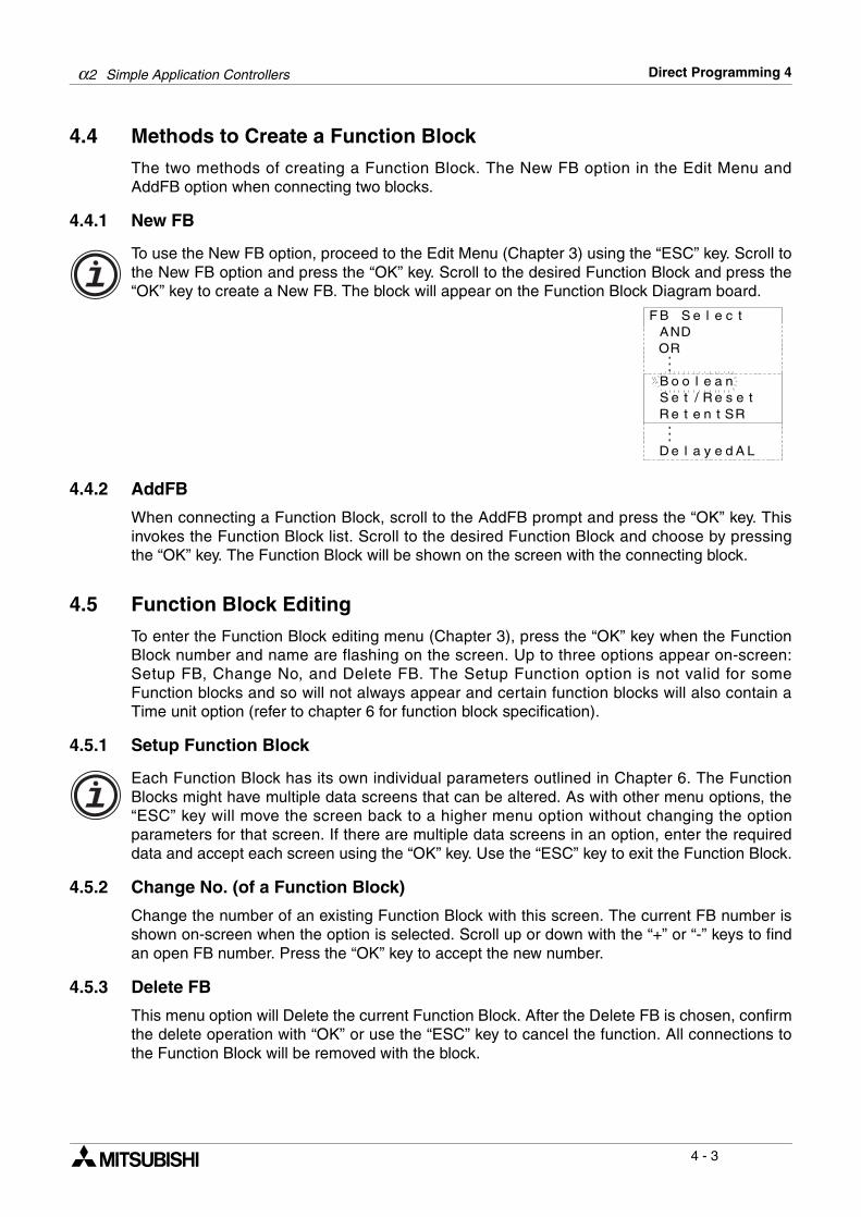
4.4 Methods to Create a Function Block
The two methods of creating a Function Block. The New FB option in the Edit Menu andAddFB option when connecting two blocks.
4.4.1 New FB
To use the New FB option, proceed to the Edit Menu (Chapter 3) using the “ESC” key. Scroll tothe New FB option and press the “OK” key. Scroll to the desired Function Block and press the“OK” key to create a New FB. The block will appear on the Function Block Diagram board.
4.4.2 AddFB
When connecting a Function Block, scroll to the AddFB prompt and press the “OK” key. Thisinvokes the Function Block list. Scroll to the desired Function Block and choose by pressingthe “OK” key. The Function Block will be shown on the screen with the connecting block.
4.5 Function Block Editing
To enter the Function Block editing menu (Chapter 3), press the “OK” key when the FunctionBlock number and name are flashing on the screen. Up to three options appear on-screen:Setup FB, Change No, and Delete FB. The Setup Function option is not valid for someFunction blocks and so will not always appear and certain function blocks will also contain aTime unit option (refer to chapter 6 for function block specification).
4.5.1 Setup Function Block
Each Function Block has its own individual parameters outlined in Chapter 6. The FunctionBlocks might have multiple data screens that can be altered. As with other menu options, the“ESC” key will move the screen back to a higher menu option without changing the optionparameters for that screen. If there are multiple data screens in an option, enter the requireddata and accept each screen using the “OK” key. Use the “ESC” key to exit the Function Block.
4.5.2 Change No. (of a Function Block)
Change the number of an existing Function Block with this screen. The current FB number isshown on-screen when the option is selected. Scroll up or down with the “+” or “-” keys to findan open FB number. Press the “OK” key to accept the new number.
4.5.3 Delete FB
This menu option will Delete the current Function Block. After the Delete FB is chosen, confirmthe delete operation with “OK” or use the “ESC” key to cancel the function. All connections tothe Function Block will be removed with the block.
eleSBF tcA DNOR
naeloB o/teS se teeteR tn RS
aleD ey Ad L
R

α2 Simple Application Controllers Direct Programming 4
4 - 4
4.6 Movement between Function Blocks
There are a number of ways to move from one item to another when in the ProgEdit or Monitormodes.
4.6.1 Movement Between Unconnected Blocks
Movement between System Inputs, System Outputs, Keys, and M bits can be accomplishedwith the “+” and “-” keys. When the block number is flashing on-screen, press the “+” key toscroll to the higher value of the same block type; e.g. move from I01 to I02 to I03...until thehighest value is reached. The scroll will then proceed to the lowest value of the next block type.The same technique will work for the “-” key in the opposite direction.Function Blocks can be scrolled through in the same manner, although only the FunctionBlocks are rotated through in this case.
4.6.2 Movement Between Connected Blocks
The Right arrow moves horizontally (to the right) along the path of connections betweenblocks. If an output pin is connected to multiple input pins, the current path will flash. The Upand Down arrows can be used to choose the desired path. The left arrow will move back alongthe path of the connections to the left.
4.6.3 The Jump Command
The “ESC” key can be used to enter the Edit Menu at anytime when a function block isdisplayed on the LCD screen. (The “ESC” key will cancel in-process commands first. Keeppressing the “ESC” key until the Edit Menu is displayed). Select the Jump Command. Chooseany system Memory Bit, Input, Output, Key, AS-i Input, AS-i Output, Extended Input, ExtendedOutput, or existing Function Block by using the front panel keys. Press “OK” to “Jump” to thechosen block in the programming mode.
4.7 Using Keys as Inputs
Connect the Keys for use as Manual Inputs by using the Jump command to access the desiredkey, by connecting a Function Block or Output as described in Chapter 3, or by scrollingthrough the blocks as described in section 4.6.1. The programmed Key(s) will give an output signal for as long as the key is depressed.
eMtdE unziSgrP o
pmuJweN BF
e
tixEinomnM e c
i
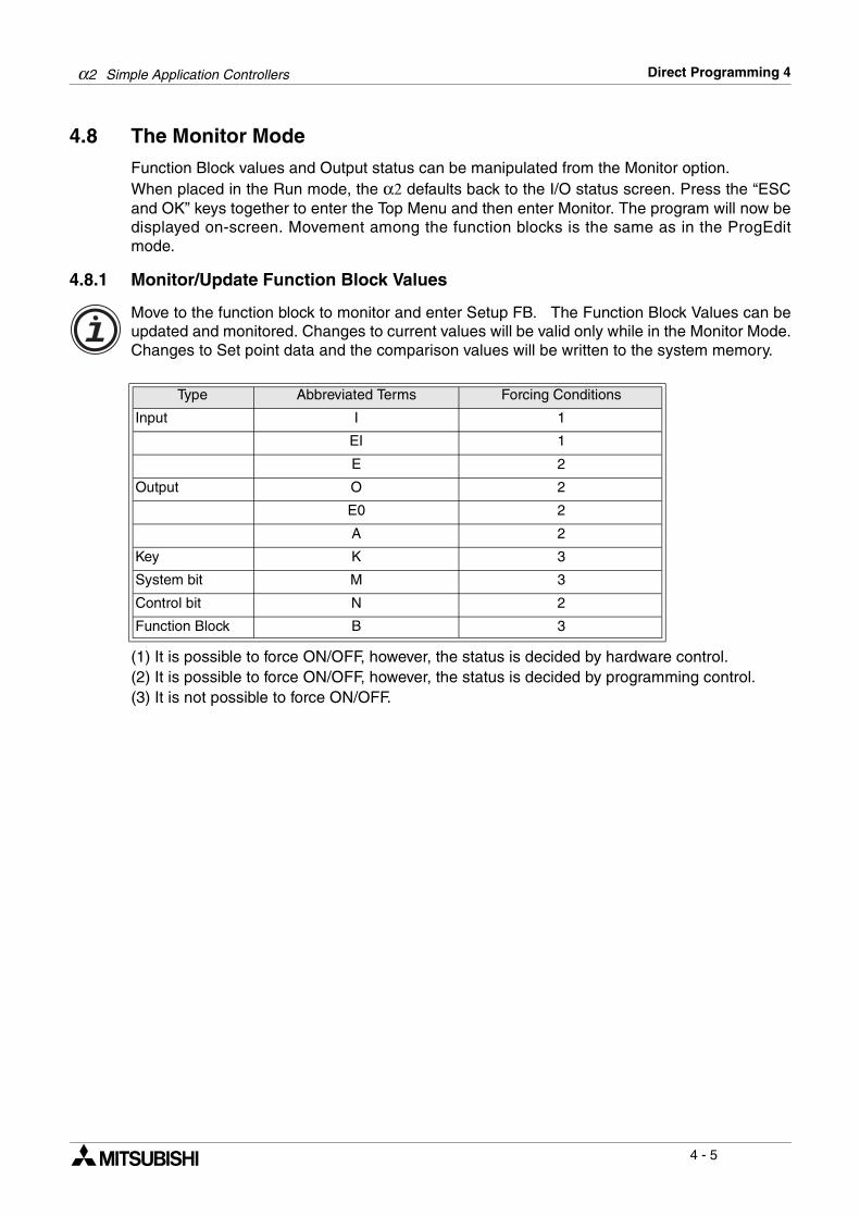
α2 Simple Application Controllers Direct Programming 4
4 - 5
4.8 The Monitor Mode
Function Block values and Output status can be manipulated from the Monitor option.When placed in the Run mode, the α2 defaults back to the I/O status screen. Press the “ESCand OK” keys together to enter the Top Menu and then enter Monitor. The program will now bedisplayed on-screen. Movement among the function blocks is the same as in the ProgEditmode.
4.8.1 Monitor/Update Function Block Values
Move to the function block to monitor and enter Setup FB. The Function Block Values can beupdated and monitored. Changes to current values will be valid only while in the Monitor Mode.Changes to Set point data and the comparison values will be written to the system memory.
(1) It is possible to force ON/OFF, however, the status is decided by hardware control.(2) It is possible to force ON/OFF, however, the status is decided by programming control.(3) It is not possible to force ON/OFF.
Type Abbreviated Terms Forcing Conditions
Input I 1
EI 1
E 2
Output O 2
E0 2
A 2
Key K 3
System bit M 3
Control bit N 2
Function Block B 3
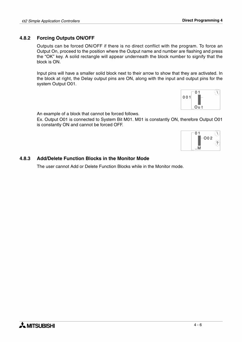
α2 Simple Application Controllers Direct Programming 4
4 - 6
4.8.2 Forcing Outputs ON/OFF
Outputs can be forced ON/OFF if there is no direct conflict with the program. To force anOutput On, proceed to the position where the Output name and number are flashing and pressthe “OK” key. A solid rectangle will appear underneath the block number to signify that theblock is ON.
Input pins will have a smaller solid block next to their arrow to show that they are activated. Inthe block at right, the Delay output pins are ON, along with the input and output pins for thesystem Output O01.
An example of a block that cannot be forced follows. Ex. Output O01 is connected to System Bit M01. M01 is constantly ON, therefore Output O01is constantly ON and cannot be forced OFF.
4.8.3 Add/Delete Function Blocks in the Monitor Mode
The user cannot Add or Delete Function Blocks while in the Monitor mode.
1
uO
000 1
t
\
1
M
0 \0O 2
?_
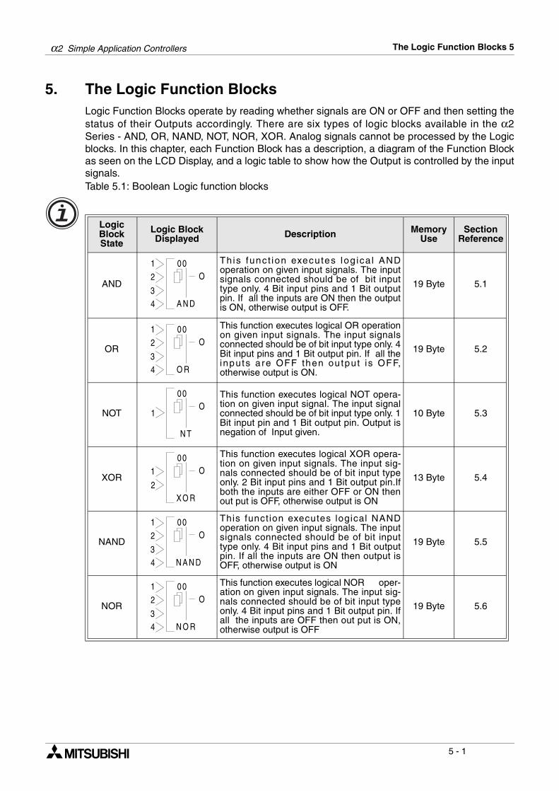
α2 Simple Application Controllers The Logic Function Blocks 5
5 - 1
5. The Logic Function BlocksLogic Function Blocks operate by reading whether signals are ON or OFF and then setting thestatus of their Outputs accordingly. There are six types of logic blocks available in the α2Series - AND, OR, NAND, NOT, NOR, XOR. Analog signals cannot be processed by the Logicblocks. In this chapter, each Function Block has a description, a diagram of the Function Blockas seen on the LCD Display, and a logic table to show how the Output is controlled by the inputsignals.Table 5.1: Boolean Logic function blocks
Logic Block State
Logic Block Displayed Description Memory
UseSection
Reference
AND
This func t ion executes log ica l ANDoperation on given input signals. The inputsignals connected should be of bit inputtype only. 4 Bit input pins and 1 Bit outputpin. If all the inputs are ON then the outputis ON, otherwise output is OFF.
19 Byte 5.1
OR
This function executes logical OR operationon given input signals. The input signalsconnected should be of bit input type only. 4Bit input pins and 1 Bit output pin. If all theinputs are OFF then output i s OFF,otherwise output is ON.
19 Byte 5.2
NOT
This function executes logical NOT opera-tion on given input signal. The input signalconnected should be of bit input type only. 1Bit input pin and 1 Bit output pin. Output isnegation of Input given.
10 Byte 5.3
XOR
This function executes logical XOR opera-tion on given input signals. The input sig-nals connected should be of bit input typeonly. 2 Bit input pins and 1 Bit output pin.Ifboth the inputs are either OFF or ON thenout put is OFF, otherwise output is ON
13 Byte 5.4
NAND
This funct ion executes logical NANDoperation on given input signals. The inputsignals connected should be of bit inputtype only. 4 Bit input pins and 1 Bit outputpin. If all the inputs are ON then output isOFF, otherwise output is ON
19 Byte 5.5
NOR
This function executes logical NOR oper-ation on given input signals. The input sig-nals connected should be of bit input typeonly. 4 Bit input pins and 1 Bit output pin. Ifall the inputs are OFF then out put is ON,otherwise output is OFF
19 Byte 5.6
00
A N D
2
3
O
4
1
00
O R
2
3
O
4
1
00
N T
1O
00
XO R
1
2
O
00
N A N D
2
3
O
4
1
00
N O R
2
3
O
4
1
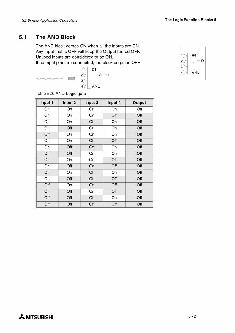
α2 Simple Application Controllers The Logic Function Blocks 5
5 - 2
5.1 The AND Block
The AND block comes ON when all the inputs are ON.Any Input that is OFF will keep the Output turned OFF.Unused inputs are considered to be ON.If no Input pins are connected, the block output is OFF.
Table 5.2: AND Logic gate
Input 1 Input 2 Input 3 Input 4 Output
On On On On On
On On On Off Off
On On Off On Off
On Off On On Off
Off On On On Off
On On Off Off Off
On Off Off On Off
Off Off On On Off
Off On On Off Off
On Off On Off Off
Off On Off On Off
On Off Off Off Off
Off On Off Off Off
Off Off On Off Off
Off Off Off On Off
Off Off Off Off Off
00
A N D
2
3
O
4
1
01
AND
Output
1
2
3
4
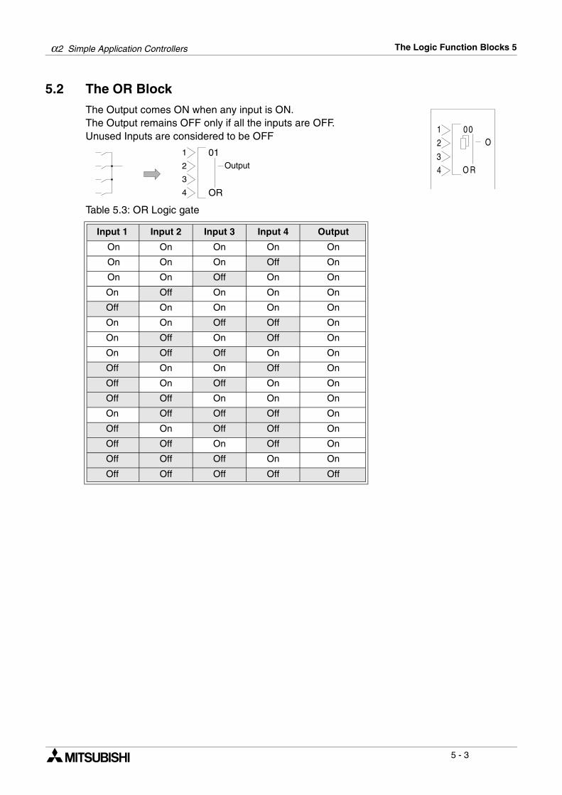
α2 Simple Application Controllers The Logic Function Blocks 5
5 - 3
5.2 The OR Block
The Output comes ON when any input is ON.The Output remains OFF only if all the inputs are OFF.Unused Inputs are considered to be OFF
Table 5.3: OR Logic gate
Input 1 Input 2 Input 3 Input 4 Output
On On On On On
On On On Off On
On On Off On On
On Off On On On
Off On On On On
On On Off Off On
On Off On Off On
On Off Off On On
Off On On Off On
Off On Off On On
Off Off On On On
On Off Off Off On
Off On Off Off On
Off Off On Off On
Off Off Off On On
Off Off Off Off Off
00
O R
2
3
O
4
1
01
OR
Output
1
2
3
4
α2 Simple Application Controllers The Logic Function Blocks 5
5 - 4
5.3 The NOT Block
The NOT block takes a signal and inverts it - an Input that is ONhas an Output that is OFF, and vice versa.The Output comes ON when the input is OFF.The Output is OFF when the input is ON.If no Input pin is used, the block output is OFF.The electrical circuit for a NOT block is the same as a NormallyClosed input.Table 5.4: NOT Logic gate
5.4 The XOR Block (Exclusive OR)
The Output comes ON when one input is ON and one is OFF. TheOutput remains OFF when both Inputs are equivalent (either bothON or both OFF).Unused Inputs are considered to be OFF.Table 5.5: XOR Logic gate
Input Output
On Off
Off On
Input 1 Input 2 Output
On On Off
On Off On
Off On On
Off Off Off
00
N T
1O
00
X O R
1
2
O
α2 Simple Application Controllers The Logic Function Blocks 5
5 - 5
5.5 The NAND Block (Not AND)
The Output comes ON if any or all inputs are OFF.If every input is ON, the Output turns OFF.Unused Inputs are considered to be ON.If no Input pin is used, the block output is OFF.(This is equivalent to an AND block followed by a NOT block)
.Table 5.6: NAND Logic gate
Input 1 Input 2 Input 3 Input 4 Output
On On On On Off
Off Off Off Off On
On On On Off On
On On Off On On
On Off On On On
Off On On On On
On On Off Off On
On Off On Off On
On Off Off On On
Off On On Off On
Off On Off On On
Off Off On On On
On Off Off Off On
Off On Off Off On
Off Off On Off On
Off Off Off On On
00
N A N D
2
3
O
4
1
01
NAND
Output
1
2
3
4
α2 Simple Application Controllers The Logic Function Blocks 5
5 - 6
5.6 The NOR Block (Not OR)
The Output comes ON when all the inputs are OFF.The Output remains OFF if any input is ON.If no Input pin is used, the block output is OFF.Unused Inputs are considered to be OFFThis block is equivalent to an OR block followed by a NOT block
Table: 5.7: NOR Logic gate
Input 1 Input 2 Input 3 Input 4 Output
Off Off Off Off On
On On On On Off
On On On Off Off
On On Off On Off
On Off On On Off
Off On On On Off
On On Off Off Off
On Off On Off Off
On Off Off On Off
Off On On Off Off
Off On Off On Off
Off Off On On Off
On Off Off Off Off
Off On Off Off Off
Off Off On Off Off
Off Off Off On Off
00
N O R
2
3
O
4
1
01
NOR
Output
1
2
3
4
α2 Simple Application Controllers Function Blocks 6
6 - 1
6. Function BlocksThe α2 series controller is fundamentally based on function block programming. The blocksprovide a wide range of possible operations and have been preprogrammed for ease of use.Some Function Blocks have parameters that can be tailored to meet individual requirements inthe programs. Each function block will have a description of the Block’s purpose, a diagram ofhow the Block will appear on-screen, and a description of the inputs, outputs, and availableoptions.Table 6.1: Function Block List
FB Name FB Symbol Description of Function Block Memory Use Section
Boolean[BL]
The Boolean Function Block uses Booleanalgebra to control the ON/OFF state of anoutput. An operational expression consistsof either the AND, OR, NOR, XOR or NOTform.
*1 6.3
Set/Reset[SR]
The Set/Reset Function Block either holdsan output ON (set) or releases the outputOFF (reset.) Priority can be given to eitherinput pin if both inputs have been energisedsimultaneously. The default priority settingis dedicated to the reset input pin.
14 Byte 6.4
Pulse[PL]
The Pulse Function Block sends a singlepulse to the output pin if the input pinreceives either an “ON to OFF”, “OFF toON” or “ON to OFF And OFF to ON” inputoperation.
10 Byte 6.5
Alternate[AL]
The Alternate Function Block is used toreverse the ON and OFF state of the outputas and when the input pin receives a signal.The output will be set ON when the inputpin goes high and remain ON until the inputreceives the second rising edge.
13 Byte 6.6
Delay[DL]
The Delay Function Block provides an ONdelay timer and an OFF delay timer. Timeintervals for either situation can be set. Thetime unit can be set to 10ms, 100ms or 1sincrements.
19 Byte 6.7
One Shot[OS]
The One Shot Function Block awaits asignal supplied to the input pin thereaftersetting the output according to the specifiedtime. The timing parameters control thestate of the output (depending on thepriority setting). The time unit can be set to10ms, 100ms or 1s increments.
17 Byte 6.8
Flicker[FL]
The Flicker Function Block changes the ONand OFF state of the output according to apreset flicker time. The time unit can be setto 10ms, 100ms or 1s increments.
19 Byte 6.9
0 001
LB
O234
P
0 00
RS
OSR
P
0 00
LP
OI P
0 00
LA
OIC
0 00
LD
OIC
P
0 00
SO
OIC
P
0 00
LF
OI P
α2 Simple Application Controllers Function Blocks 6
6 - 2
Time Switch
[TS]
The Time Switch Function Block uses apredefined time schedule to control the ONand OFF status of the output.
*2 6.10
Time Switch m
[TSm]
The Time Switch maintenance FunctionBlock uses a predefined time schedule tocontrol the ON and OFF status of theoutput. The function block can be setupfrom the TopMenu via the front panel keys.
*2 6.10
Counter[CN]
The Counter Function Block increments thecurrent value by one as and when the inputpin receives a signal. When the currentvalue reaches the set value the output is setON. The counter current value is reset asand when the clear pin receives an input.
16 Byte 6.11
U/D Counter
[UD]
The Up/Down Function block positively ornegatively increments the counter until aset value is reached thereby setting theoutput ON. A preset signal can also equalthe set value regardless of the current valuefor the function block and thereby settingthe output ON.
22 Byte 6.12
Compare[CP]
The Compare Function Block monitors thecurrent value of the input pin in relation to apreset expression. The expression consistsof =,>,>=,<,<= or <>. If the compared valuesatisfies the expression subsequently theoutput pin is set on.
17 Byte 6.13
Analog Output
The Analog Output function takes a digitalvalue input and delivers a correspondinganalog voltage or current to a selectedchannel on the AL2-2DA module.
17 Byte 6.14
Offset Gain[OG]
The Offset Gain Function Block is basedupon a linear function Y=A/B∗X+C to whichthe value obtained from an analog input(X:A01-A08) is set.
22Byte 6.15
Display[DP]
The Display Function Block is used as aninterface between the user and the devicesheld within the controller. Current values,timer messages, user-defined messagescan be read.
*4 6.16
Zone Compare
[ZC]
The Zone Compare Func t ion B lockidentifies whether the input value lies withina specified upper and lower limited zonalarea and if so changes the status of theoutput accordingly.
20 Byte 6.17
FB Name FB Symbol Description of Function Block Memory Use Section
0 00
ST
OP
0 00
ST m
P
0 00
NC
OIC
P
0 00U
DU
ODCP
P
0 00
PC
OI P
0 00
OA
I P
0 00
GO
I P
0 00
PD
I P
0 00
CZ
OI P
α2 Simple Application Controllers Function Blocks 6
6 - 3
Schmitt Trigger
[ST]
The Schmi t t Tr igger Funct ion B lockcompares an input value to preset high andlow limits. The output is ON when the inputvalue reaches the high limit and then fallsbelow the lower limit. The function onlyprocesses the data when the function blockis receiving an input signal.
19 Byte 6.18
Hour Meter[HM]
The Hour Meter Function Block holds theoutput status ON for a maximum of 32767hours, 59 minutes and 59 seconds. If theinput pin is turned OFF the elapsed timewill hold its value until either the clear pinresets the time or the input pin is turned ONagain.
19 Byte 6.19
Speed Detect[SPD]
The Speed Detect Function Block is used tocount the incoming pulses max. 20Hz (withan extension module max. of 1kHz) for aset period of time. The upper and lowerlimits can be set from -32768 to +32767and the Period interval’s set range is 1 to32767 in 10ms increments.
25 Byte 6.20
PWM[PWM]
The Pulse Width Modulation Function Blockchanges the output status according to aset period of time with a minimum of 100msand a max imum of 3276700ms inincrements of 100ms. The percentage dutyfor the function controls the amount ofelapsed time before the output status ischanged.
16 Byte 6.21
PID
The P ID Func t ion B lock i s the α2implementation of PID, a control methodused to obtain stable control over a systemvariable. It is a equipped with an Auto-tuning function, which automatically adjuststhe Function Block parameters for thespecific application.
52 Byte 6.22
Retentive Alternate
[RAL]
The Alternate Function Block is used toreverse the ON and OFF state of the outputas and when the input pin receives a signal.The output will be set ON when the inputpin goes high and remain ON until the inputreceives the second rising edge. When thepower is turned OFF the function block willuse the last alternation operation to controlthe output.
13 Byte 6.23
Addition[ADD]
The ADD Funct ion B lock is used tosummate two input values 20 Byte 6.24
Subtraction
[SUB]
The SUB Function Block is used to subtracttwo input values. 20 Byte 6.25
FB Name FB Symbol Description of Function Block Memory Use Section
0 00
TS
OI P
0 00
MH
OIC
P
0 00
PS
OUC
I
D
P
0 00
WP
OI
M
P
0 00
IP
OEC
A
D
P0 00
IP
OAC
E
D
P
0 00
LA
OIC
R
0 00
DA
OI
D
P
0 00
US
OI
B
P
α2 Simple Application Controllers Function Blocks 6
6 - 4
Multiplication
[MUL]
The MUL Function Block is used to multiplytwo input values. 20 Byte 6.26
Division[DIV]
The DIV Function Block is used to dividetwo input values. 20 Byte 6.27
Calculation
[CAL]
The CAL Function Block is used to performa calculation from the combination ofdifferent Arithmetic function blocks.
*3 6.28
Shift[SFT]
This Shift Function Block is used to transferthe Shift Input status just before the Inputsignal is set ON. It has a bit input pin, a shiftinput pin, a set input pin, a reset input pinand a bit output pin.
19 Byte 6.29
SMS[SMS]
The GSM SMS Function Block sends theLCD screen as a SMS message to either amobile phone handset or an E-mail accountfor remote maintenance purposes.
*6 6.30
Random One Shot
[ROS]
The Random One Shot Function Blockemits a random length single pulse to theoutput.
19 Byte 6.31
Delayed One Shot
[DOS]
The Delayed One Shot Function Blockemits a single pulse after a controlled delayto the output.
20 Byte 6.32
Delayed Alternate
[DAL]
The Delayed Alternate Function Blockalternates the status of the output with eachpulse after a controlled delay.
16 Byte 6.33
FB Name FB Symbol Description of Function Block Memory Use Section
0 00
UM
OI
L
P
0 00
ID
OI
V
P
0 00
AC
OI
L
P
0 00I
TS
OTSR F
P
0 00
MS
OI
S
P
0 00
OR
OI
SC
P
0 00
OD
OI
SC
P
0 00
AD
OI
LC
P
α2 Simple Application Controllers Function Blocks 6
6 - 5
Note:
*1 Number of bytes used = 19 + 1 x (Characters in equation)
*2 Number of bytes used = 8 + 4 x (Number of time switches)
*3 Number of bytes used = 30 + 1 x (Characters in equation)
*4 Number of bytes used is decided by the displayed item.
*5 Number of bytes used = 32 + 3 x (Number of screen)
*6 Number of bytes used = 12 + 1 x (Characters in E-Mail address)
Retentive Set/Reset
[RSR]
The Set/Reset Function Block either holdsan output ON (set) or releases the outputOFF (reset.) Priority can be given to eitherinput p in i f bo th i npu ts have beenenergised. The default priority setting isdedicated to the reset input pin. When thepower is turned OFF the function block willuse the last set or reset operation to controlthe output.
14 Byte 6.34
Control Display[CDP]
The Control Display Function allows theuser to control the LCD image screens. Thefunc t ion b lock can on ly be se t i nAL-PCS/WIN-E software for Alpha SeriesControllers. When control bit N04 is ON, itis possible to control the displayed UserScreen.
*5 6.35
Connect[ _B ]
The Connect function block is an internaldevice used to show the memory used byinput bits, system bits, AS-interface bits,and the operation keys. No function blockappears on screen or is shown as beingused in the “Memory Configuration Usage”dialog box. The purpose is only to calculatethe memory that is used by the bits listedabove.
10 Btye 6.36
System Outputs
Control for external devices through relays and transistors.
10 Btye -
Displayed Item Number of bytes, α2 Series
Characters 16 + 1 x (Each character displayed)
Analog, FB valueValue 17
Graph 23
Time, Date 14
Time Switch 17
FB Name FB Symbol Description of Function Block Memory Use Section
0 00
SR
OSR
R
P
00
B_
OI0
α2 Simple Application Controllers Function Blocks 6
6 - 6
6.1 Definitions
DirectSet - Enter a value using the “+” and “-” keys.Analog In - An analog input value from a System Input (A01, A02, A03,... A08).FB Value - A value contained in a Function Block (T, t, N, n, Direct set, etc.)Word Comparison - a 16 bit output value from a Function Block.
6.2 Abbreviations
Table 6.2: Abbreviated terms used in describing function block
Note: The following function block information, details specific explanation concerningfront panel programming using the α2 Series Controller. However, it is assumed theuser has read and understood Direct Programming Chapter 4. Thus, is capable ofconnecting function blocks together using the dedicated front panel keys. Hence, eachfunction block provides step by step instructions for direct input having ignored theinitial key presses detailed in Chapter 4.
Term Description
I Input pin for function block operation
1,2,3,4 Numbered Input pins for boolean logic type function blocks
O Output pin for function block operation
S Set pin for the function block
R Reset pin for the function block
C Clear pin for the function block
U Increments a positive count to the Up/Down Counter Function Block
D Increments a negative count to the Up/Down Counter Function Block
P Preset signal input pin for the Up/Down Function Block
N The count value set by the user, range: 0 - 32767
n The actual count value. This value can be set to a one time offset value,range: 0 - 32767
T For Shift function block only. Shift input pin
T User specified Set Time Value, range: 0 - 3276.7sec
t The elapsed time since the function set ON, range: 0 - 32767sec

α2 Simple Application Controllers Function Blocks 6
6 - 7
6.3 Boolean block
The function block creates a logical operation using Boolean algebra consisting of AND, OR,NAND, XOR and NOT gates. It is possible to express the Logic functions in the form of anequation. Refer to Chapter 5 for detailed information concerning Boolean Logic operation.
Table 6.3: Boolean Function Block
Table 6.4: Boolean expressional data
1 ) Boolean Operation
Function Set Item Description
1,2,3,4 Numbered Input pins for boolean operation to control
FB User-defined logical boolean operation
Output The output is controlled directly from the result of the booleanoperation involving the numbered input pins 1,2,3,4.
Item Display Description
AND ∗ Intersection
OR + Disjunction
XOR ^ XOR
NOT ! NOT
( ( Left parenthesis
) ) Right parenthesis
1 1 Signal connected to Input pin 1
2 2 Signal connected to Input pin 2
3 3 Signal connected to Input pin 3
4 4 Signal connected to Input pin 4
O O Output signal
= = Equal sign signal
0 001
LB
O234
P
01
BL
Output
1
2
3
1 2
3 O = 1 2 + 3
AND OR
*
α2 Simple Application Controllers Function Blocks 6
6 - 8
Setup of the Boolean Function Block directly from the α2 Series Controller
1 ) Allocate the input pin to be used for the function block.
2 ) Press the “OK” key with the cursor in the function block. The function block edit screen isdisplayed as shown.
3 ) Select Setup FB using the “ and ” keys and press the “OK” key. The boolean functionblock edit screen is displayed as shown.
4 ) Enter the boolean expression via the “ , , and keys”. A boolean expression isdisplayed as shown.
5 ) Press the “OK” key after entering the boolean expression.
B 0 0 1 : B LS e t u p F BC h a n g e N oD e l e t e F B
B 0 0 1 : B LO=
3[ ]
B 0 0 1 : B LO= 1 + 2 + 3
OR
3[ ]
α2 Simple Application Controllers Function Blocks 6
6 - 9
6.4 Set/Reset Block
The function block will set or reset an output according to the input condition. When the SETinput is energised, the Output is ON. When the RESET input is energised, the Output is OFF.When both inputs are energised simultaneously, the Output will follow the Priority Settingsignal. A latched Output does not depend on the constant signal to retain its status.Set Priority - When the Set input comes ON, the Output comes ON and remains ON until theReset pin receives a signal. Once the Output is ON, the Set input signal can turn OFF withouteffecting the Output. If both the Set and Reset pins are ON, the Output is ON.Reset Priority - The operation is the same as the Set Priority except that when both pins areON, the Output is OFF.
Table 6.5: Set/Rest Function Block
1 ) Operation of reset priority
2 ) Operation of set priority
Function Set Item Description
S Set pin for the function block
R Reset pin for the function block
FB Allocates priority to either the set or reset function when both pins areON
Output
The output of the function block operates in either an ON or OFFstate.
1) Set the output ON until the reset pin is ON.
2) Decides the status of the output depending which input pin haspriority.
0 00
RS
OSR
P
ONOFF
OFFON
ON OFF
Input pin S
Input pin R
Output
ONOFF
OFFON
ON OFF
Input pin S
Input pin R
Output
α2 Simple Application Controllers Function Blocks 6
6 - 10
Setup of the Set/Reset Function Block directly from the α2 Series Controller
1 ) Allocate the set and reset pins for the function block.
2 ) Press the “OK” key with the cursor in the function block. The function block edit screen isdisplayed as shown.
3 ) Select Setup FB using the “ and ” keys and press the “OK” key. The Set/Reset priorityscreen is displayed as shown.
4 ) Select the Set or Reset priority using the “ and ” keys and press the “OK” key to returnto the function block edit screen.
B 0 0 1 : SS e t u p F BC h a n g e N oD e l e t e F B
R
S e tR e s e t
P r i o r i t yB 0 0 1 : SR
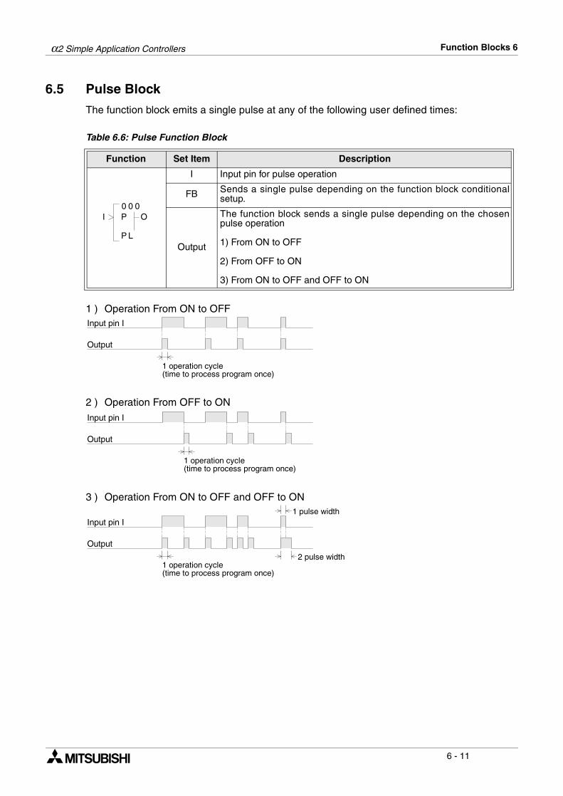
α2 Simple Application Controllers Function Blocks 6
6 - 11
6.5 Pulse Block
The function block emits a single pulse at any of the following user defined times:
Table 6.6: Pulse Function Block
1 ) Operation From ON to OFF
2 ) Operation From OFF to ON
3 ) Operation From ON to OFF and OFF to ON
Function Set Item Description
I Input pin for pulse operation
FB Sends a single pulse depending on the function block conditionalsetup.
Output
The function block sends a single pulse depending on the chosenpulse operation
1) From ON to OFF
2) From OFF to ON
3) From ON to OFF and OFF to ON
0 00
LP
OI P
Input pin I
Output
1 operation cycle(time to process program once)
Input pin I
Output
1 operation cycle(time to process program once)
Input pin I
Output
1 operation cycle(time to process program once)
2 pulse width
1 pulse width

α2 Simple Application Controllers Function Blocks 6
6 - 12
Setup of the Pulse Function Block directly from the α2 Series Controller
1 ) Allocate the input pin to be used for the function block.
2 ) Press the “OK” key with the cursor in the function block. The function block edit screen isdisplayed as shown.
3 ) Select Setup FB using the “ and ” keys and press the “OK” key. Select using the “and ” keys the initiation type for the pulse operation.
4 ) Press the “OK” key to return to the function block edit screen.
S e t u p F BC h a n g e N oD e l e t e F B
B 0 0 1 : P L
R i s e E d gF a l l E d g eB o t h E d g e
B 0 0 1 : P Le

α2 Simple Application Controllers Function Blocks 6
6 - 13
6.6 Alternate Block
The function block inflicts a reversal of the ON and OFF state of the output as and when theinput is given to the input pin.
Table 6.7: Alternate Function Block
1 ) Alternate Operation
Function Set Item Description
I Input pin for alternation operation
C Clear input pin resets the state of the output regardless of the inputgiven.
FB N/A
Output
The output is affected in the following operation:
1) Reverse the ON/OFF state of the output whenever the inputsignal’s ON/OFF operation to the input pin is turned ON (ON to OFFor OFF to ON)
2) The clear selection resets the output regardless of the input given.
0 00
LA
OIC
Input pin I
Input pin C
Output
ON OFFON
OFF
ON OFF
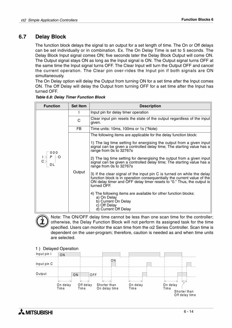
α2 Simple Application Controllers Function Blocks 6
6 - 14
6.7 Delay Block
The function block delays the signal to an output for a set length of time. The On or Off delayscan be set individually or in combination. Ex. The On Delay Time is set to 5 seconds. TheDelay Block Input signal comes ON; five seconds later the Delay Block Output will come ON.The Output signal stays ON as long as the Input signal is ON. The Output signal turns OFF atthe same time the Input signal turns OFF. The Clear Input will turn the Output OFF and cancelthe current operation. The Clear pin over-rides the Input pin if both signals are ONsimultaneously.The On Delay option will delay the Output from turning ON for a set time after the Input comesON. The Off Delay will delay the Output from turning OFF for a set time after the Input hasturned OFF.Table 6.8: Delay Timer Function Block
Note: The ON/OFF delay time cannot be less than one scan time for the controller;otherwise, the Delay Function Block will not perform its assigned task for the timespecified. Users can monitor the scan time from the α2 Series Controller. Scan time isdependent on the user-program; therefore, caution is needed as and when time unitsare selected.
1 ) Delayed Operation
Function Set Item Description
I Input pin for delay timer operation
C Clear input pin resets the state of the output regardless of the inputgiven.
FB Time units: 10ms, 100ms or 1s (*Note)
Output
The following items are applicable for the delay function block:
1) The lag time setting for energising the output from a given inputsignal can be given a controlled delay time; The starting value has arange from 0s to 32767s
2) The lag time setting for denergising the output from a given inputsignal can be given a controlled delay time; The starting value has arange from 0s to 32767s
3) If the clear signal of the input pin C is turned on while the delayfunction block is in operation consequentially the current value of theON delay timer and OFF delay timer resets to “0.” Thus, the output isturned OFF.
4) The following items are available for other function blocks: a) On Delay b) Current On Delay c) Off Delay d) Current Off Delay
0 00
LD
OIC
P
Input p in I
Inpu t p in C
O N
O utput
O n de layTim e
S horte r thanO n de lay tim e
O ff de layTim e
O N O FF
O N
O n de layTim e
S horte r thanO ff de lay tim e
O n de layTim e
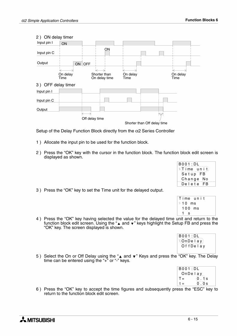
α2 Simple Application Controllers Function Blocks 6
6 - 15
2 ) ON delay timer
3 ) OFF delay timer
Setup of the Delay Function Block directly from the α2 Series Controller
1 ) Allocate the input pin to be used for the function block.
2 ) Press the “OK” key with the cursor in the function block. The function block edit screen isdisplayed as shown.
3 ) Press the “OK” key to set the Time unit for the delayed output.
4 ) Press the “OK” key having selected the value for the delayed time unit and return to thefunction block edit screen. Using the “ and ” keys highlight the Setup FB and press the“OK” key. The screen displayed is shown.
5 ) Select the On or Off Delay using the “ and ” Keys and press the “OK” key. The Delaytime can be entered using the “+” or “-” keys.
6 ) Press the “OK” key to accept the time figures and subsequently press the “ESC” key toreturn to the function block edit screen.
Input pin I
Input pin C
ON
Output
On delayTime
Shorter thanOn delay time
ON OFF
ON
On delayTime
On delayTime
Input pin I
Input pin C
Output
Off delay timeShorter than Off delay time
B 0 0 1 : D L
S e t u p F BC h a n g e N oD e l e t e F B
T i me u n i t
1 0 msT i me u n i t
1 0 ms1 s
0
B 0 0 1 : D LO n D e l aO f f D e l a y
y
B 0 0 1 : D LO n D e l a
T = 0 . 1 sy
t = 0 . 0 s
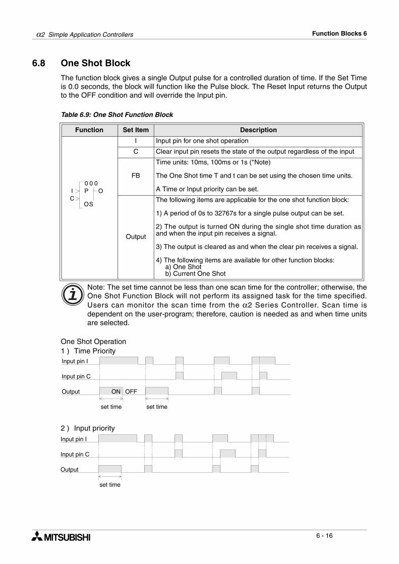
α2 Simple Application Controllers Function Blocks 6
6 - 16
6.8 One Shot Block
The function block gives a single Output pulse for a controlled duration of time. If the Set Timeis 0.0 seconds, the block will function like the Pulse block. The Reset Input returns the Outputto the OFF condition and will override the Input pin.
Table 6.9: One Shot Function Block
Note: The set time cannot be less than one scan time for the controller; otherwise, theOne Shot Function Block will not perform its assigned task for the time specified.Users can monitor the scan time from the α2 Series Controller. Scan time isdependent on the user-program; therefore, caution is needed as and when time unitsare selected.
One Shot Operation1 ) Time Priority
2 ) Input priority
Function Set Item Description
I Input pin for one shot operation
C Clear input pin resets the state of the output regardless of the input
FB
Time units: 10ms, 100ms or 1s (*Note)
The One Shot time T and t can be set using the chosen time units.
A Time or Input priority can be set.
Output
The following items are applicable for the one shot function block:
1) A period of 0s to 32767s for a single pulse output can be set.
2) The output is turned ON during the single shot time duration asand when the input pin receives a signal.
3) The output is cleared as and when the clear pin receives a signal.
4) The following items are available for other function blocks: a) One Shot b) Current One Shot
0 00
SO
OIC
P
Input pin I
Input pin C
Output ON OFF
set time set time
Input pin I
Input pin C
Output
set time
α2 Simple Application Controllers Function Blocks 6
6 - 17
Setup of the One Shot Function Block directly from the α2 Series Controller
1 ) Allocate the input pin to be used for the function block.
2 ) Press the “OK” key with the cursor in the function block. The function block edit screen isdisplayed as shown.
3 ) Press the “OK” key to set the Time unit for the delayed output.
4 ) Press the “OK” key having selected the value for the one shot time unit and return to thefunction block edit screen. Using the “ and ” keys highlight the Setup FB and press the“OK” key. The screen displayed is shown.
5 ) Select the One Shot or Priority option using the “ and ” Keys and press the “OK” key.The One Shot time can be entered using the “+” or “-” keys.
6 ) The Priority can be entered using the “ or ” keys.
7 ) Press the “OK” key to accept the time figures and subsequently press the “ESC” key toreturn to the function block edit screen.
B 0 0 1 : OS
S e t u p F BC h a n g e N oD e l e t e F B
T i me u n i t
1 0 msT i me u n i t
1 0 ms1 s
0
O n e S h oP r i o r i t y
tB 0 0 1 : OS
O n e S h oT = 1 s
t
t = 0 s
B 0 0 1 : OS
0 .0 .
P r i o r i t yB 0 0 1 : OS
T i meI n p u t
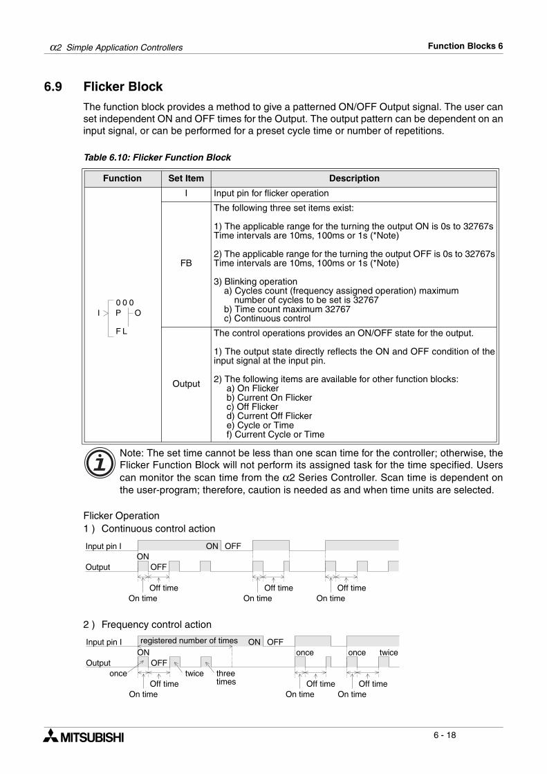
α2 Simple Application Controllers Function Blocks 6
6 - 18
6.9 Flicker Block
The function block provides a method to give a patterned ON/OFF Output signal. The user canset independent ON and OFF times for the Output. The output pattern can be dependent on aninput signal, or can be performed for a preset cycle time or number of repetitions.
Table 6.10: Flicker Function Block
Note: The set time cannot be less than one scan time for the controller; otherwise, theFlicker Function Block will not perform its assigned task for the time specified. Userscan monitor the scan time from the α2 Series Controller. Scan time is dependent onthe user-program; therefore, caution is needed as and when time units are selected.
Flicker Operation1 ) Continuous control action
2 ) Frequency control action
Function Set Item Description
I Input pin for flicker operation
FB
The following three set items exist:
1) The applicable range for the turning the output ON is 0s to 32767sTime intervals are 10ms, 100ms or 1s (*Note)
2) The applicable range for the turning the output OFF is 0s to 32767sTime intervals are 10ms, 100ms or 1s (*Note)
3) Blinking operation a) Cycles count (frequency assigned operation) maximum number of cycles to be set is 32767 b) Time count maximum 32767 c) Continuous control
Output
The control operations provides an ON/OFF state for the output.
1) The output state directly reflects the ON and OFF condition of theinput signal at the input pin.
2) The following items are available for other function blocks: a) On Flicker b) Current On Flicker c) Off Flicker d) Current Off Flicker e) Cycle or Time f) Current Cycle or Time
0 00
LF
OI P
Input pin I
Output
ON OFFON
OFF
On timeOff time
On timeOff time
On timeOff time
Input pin I
Output
ON OFFON
OFF
On timeOff time
On timeOff time
On timeOff time
registered number of times
once twice threetimes
once once twice
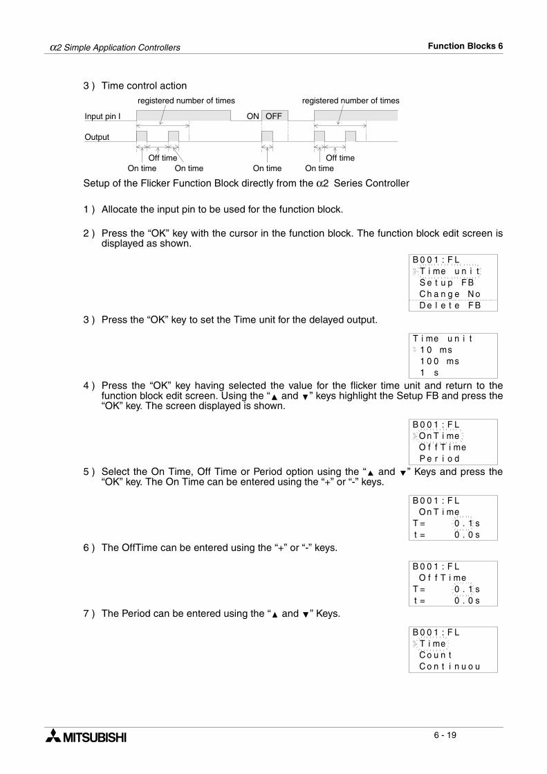
α2 Simple Application Controllers Function Blocks 6
6 - 19
3 ) Time control action
Setup of the Flicker Function Block directly from the α2 Series Controller
1 ) Allocate the input pin to be used for the function block.
2 ) Press the “OK” key with the cursor in the function block. The function block edit screen isdisplayed as shown.
3 ) Press the “OK” key to set the Time unit for the delayed output.
4 ) Press the “OK” key having selected the value for the flicker time unit and return to thefunction block edit screen. Using the “ and ” keys highlight the Setup FB and press the“OK” key. The screen displayed is shown.
5 ) Select the On Time, Off Time or Period option using the “ and ” Keys and press the“OK” key. The On Time can be entered using the “+” or “-” keys.
6 ) The OffTime can be entered using the “+” or “-” keys.
7 ) The Period can be entered using the “ and ” Keys.
Input pin I
Output
ON OFF
On timeOff time
On timeOff time
registered number of times
On time On time
registered number of times
B 0 0 1 : F L
S e t u p F BC h a n g e N oD e l e t e F B
T i me u n i t
T i me u n i t
1 0 0 sm1 0 ms
1 s
B 0 0 1 : F LO n T i meO f f T i meP e r i o d
B 0 0 1 : F L
T = 0 . 1 st = 0 . 0 s
O n T i me
B 0 0 1 : F L
T = 0 . 1 st = 0 . 0 s
O f f T i me
B 0 0 1 : F LT i meC o u n tC o n t i n u o u
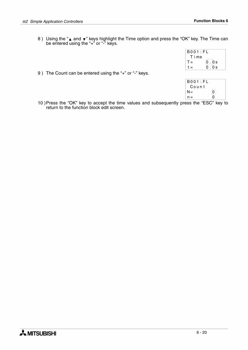
α2 Simple Application Controllers Function Blocks 6
6 - 20
8 ) Using the “ and ” keys highlight the Time option and press the “OK” key. The Time canbe entered using the “+” or “-” keys.
9 ) The Count can be entered using the “+” or “-” keys.
10 )Press the “OK” key to accept the time values and subsequently press the “ESC” key toreturn to the function block edit screen.
B 0 0 1 : F L
T = 0 . 0 st = 0 . 0 s
T i me
B 0 0 1 : F LC o u n t
N = 0n = 0
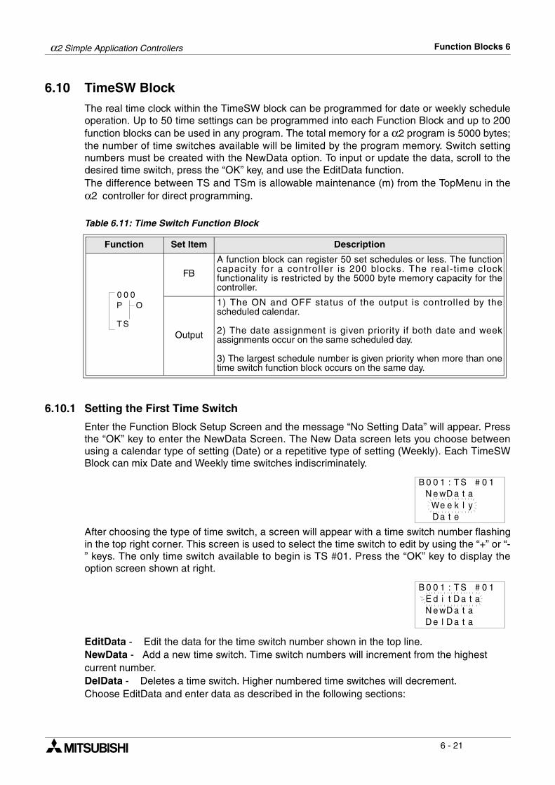
α2 Simple Application Controllers Function Blocks 6
6 - 21
6.10 TimeSW Block
The real time clock within the TimeSW block can be programmed for date or weekly scheduleoperation. Up to 50 time settings can be programmed into each Function Block and up to 200function blocks can be used in any program. The total memory for a α2 program is 5000 bytes;the number of time switches available will be limited by the program memory. Switch settingnumbers must be created with the NewData option. To input or update the data, scroll to thedesired time switch, press the “OK” key, and use the EditData function. The difference between TS and TSm is allowable maintenance (m) from the TopMenu in theα2 controller for direct programming.
Table 6.11: Time Switch Function Block
6.10.1 Setting the First Time Switch
Enter the Function Block Setup Screen and the message “No Setting Data” will appear. Pressthe “OK” key to enter the NewData Screen. The New Data screen lets you choose betweenusing a calendar type of setting (Date) or a repetitive type of setting (Weekly). Each TimeSWBlock can mix Date and Weekly time switches indiscriminately.
After choosing the type of time switch, a screen will appear with a time switch number flashingin the top right corner. This screen is used to select the time switch to edit by using the “+” or “-” keys. The only time switch available to begin is TS #01. Press the “OK” key to display theoption screen shown at right.
EditData - Edit the data for the time switch number shown in the top line.NewData - Add a new time switch. Time switch numbers will increment from the highest current number.DelData - Deletes a time switch. Higher numbered time switches will decrement.Choose EditData and enter data as described in the following sections:
Function Set Item Description
FB
A function block can register 50 set schedules or less. The functioncapacity for a controller is 200 blocks. The real-t ime clockfunctionality is restricted by the 5000 byte memory capacity for thecontroller.
Output
1) The ON and OFF status of the output is controlled by thescheduled calendar.
2) The date assignment is given priority if both date and weekassignments occur on the same scheduled day.
3) The largest schedule number is given priority when more than onetime switch function block occurs on the same day.
0 00
ST
OP
ST:10B 0#ataDeN w
keeWtaD
0 1
yle
ST:10B 0#atatdE i
aDwleD
0 1
atN eD
aD at

α2 Simple Application Controllers Function Blocks 6
6 - 22
6.10.2 For the Date operation:
The Date calendar screen is shown at the right. The setting options include the year/month/day, hour (0-23), minute, and the Output ON or OFF action.
The example shows a time switch that will turn ON on August 3rd, 2002 at 9:00 AM (Note -9:00 PM is designated on the 24 hour clock as 21:00). The day of the week is automaticallyupdated when the date is changed.
A Monthly mode is also available to the user for direct per month setting. The user can set anON or OFF condition for a specified date of the month. The time switch can also beprogrammed to perform on a yearly basis. Reduce the year to below 1998; the numberssignifying the year will display as "*" and the day of the week message will appear as “Yearly”.The operation will perform each year on the specified date.
6.10.3 For the Weekly Operation:
The Weekly Calendar is shown at right. The setting options include week of the month (0-5),day of the week, hour (0-23), minute and Output ON/OFF status. Use the left, right, up, anddown buttons to move to different locations on the LCD display.
The example screen shown at the right shows that the Output will turn ON at the followingtimes:
The first week of the month on Monday, Wednesday, and Saturday at 11:20 AM.The third week of the month on Monday, Wednesday, and Saturday at 11:20 AM.The fourth week of the month on Monday, Wednesday, and Saturday at 11:20 AM.
6.10.4 To Enter New Time Switches
Enter the Function Block Setup Menu. Enter OK until the screen at right appears. Scroll downand enter NewData. Choose either the Weekly or the Date type of switch. The TimeSwitch hasbeen created. Please see section 6.8.5 for instructions on how to enter the data.
ST:10B 0#uhT
/10:00
0 2
911 /00 o→
0 9 8ff
ST:10B 0#irF
/80:90
0 2
023 /00 o→
0 0 2n
ST:10B 0#
---:00
0 1
--- -00 o→ f
---- -
f
ST:10B 0#
-W-:11
0 1
S-- M02 o→ n
-431 -
ST:10B 0#atatdE i
aDwleD
0 1
atN eD
aD at
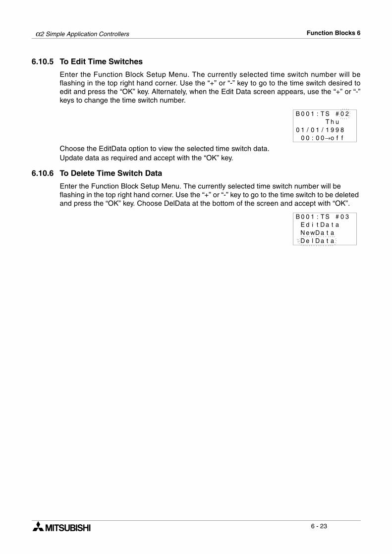
α2 Simple Application Controllers Function Blocks 6
6 - 23
6.10.5 To Edit Time Switches
Enter the Function Block Setup Menu. The currently selected time switch number will beflashing in the top right hand corner. Use the “+” or “-” key to go to the time switch desired toedit and press the “OK” key. Alternately, when the Edit Data screen appears, use the “+” or “-”keys to change the time switch number.
Choose the EditData option to view the selected time switch data.Update data as required and accept with the “OK” key.
6.10.6 To Delete Time Switch Data
Enter the Function Block Setup Menu. The currently selected time switch number will be flashing in the top right hand corner. Use the “+” or “-” key to go to the time switch to be deleted and press the “OK” key. Choose DelData at the bottom of the screen and accept with “OK”.
ST:10B 0#uhT
/10:00
0 2
911 /00 o→
0 9 8ff
ST:10B 0#atatdE i
aDwleD
0 3
atN eD
aD at
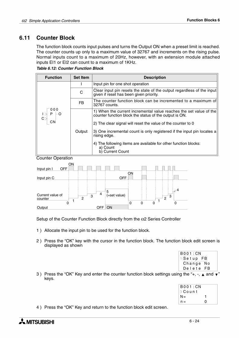
α2 Simple Application Controllers Function Blocks 6
6 - 24
6.11 Counter Block
The function block counts input pulses and turns the Output ON when a preset limit is reached.The counter counts up only to a maximum value of 32767 and increments on the rising pulse.Normal inputs count to a maximum of 20Hz, however, with an extension module attachedinputs EI1 or EI2 can count to a maximum of 1KHz.Table 6.12: Counter Function Block
Counter Operation
Setup of the Counter Function Block directly from the α2 Series Controller
1 ) Allocate the input pin to be used for the function block.
2 ) Press the “OK” key with the cursor in the function block. The function block edit screen isdisplayed as shown
3 ) Press the “OK” Key and enter the counter function block settings using the “+, -, and ”keys.
4 ) Press the “OK” Key and return to the function block edit screen.
Function Set Item Description
I Input pin for one shot operation
C Clear input pin resets the state of the output regardless of the inputgiven if reset has been given priority.
FB The counter function block can be incremented to a maximum of32767 counts.
Output
1) When the current incremental value reaches the set value of thecounter function block the status of the output is ON.
2) The clear signal will reset the value of the counter to 0
3) One incremental count is only registered if the input pin locates arising edge.
4) The following items are available for other function blocks: a) Count b) Current Count
0 00
NC
OIC
P
Input pin I
Input pin C
Current value ofcounter
ONOFF
Output
ONOFF
01
23
45(=set value)
0 0 01
23
4
0ONOFF
B 0 0 1 : CNS e t u p F BC h a n g e N oD e l e t e F B
B 0 0 1 : CNC o u n t
N = 1n = 0
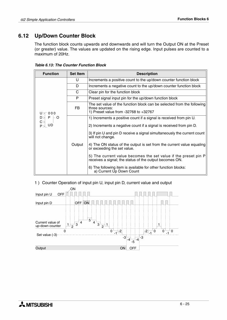
α2 Simple Application Controllers Function Blocks 6
6 - 25
6.12 Up/Down Counter Block
The function block counts upwards and downwards and will turn the Output ON at the Preset(or greater) value. The values are updated on the rising edge. Input pulses are counted to amaximum of 20Hz.
Table 6.13: The Counter Function Block
1 ) Counter Operation of input pin U, input pin D, current value and output
Function Set Item Description
U Increments a positive count to the up/down counter function block
D Increments a negative count to the up/down counter function block
C Clear pin for the function block
P Preset signal input pin for the up/down function block
FBThe set value of the function block can be selected from the followingthree sources:1) Preset value from -32768 to +32767
Output
1) Increments a positive count if a signal is received from pin U.
2) Increments a negative count if a signal is received from pin D.
3) If pin U and pin D receive a signal simultaneously the current count will not change.
4) The ON status of the output is set from the current value equalingor exceeding the set value.
5) The current value becomes the set value if the preset pin Preceives a signal; the status of the output becomes ON.
6) The following item is available for other function blocks: a) Current Up Down Count
0 00U
DU
ODCP
P
Input pin U
ON
OFF
Input pin D
Current value ofup-down counter
0
12
34
54
32
1
0-1
-2
-3-4
-5-4
-3
-2-1
0
1
0-1
0
OFF ON
Set value (-3)
Output ON OFF
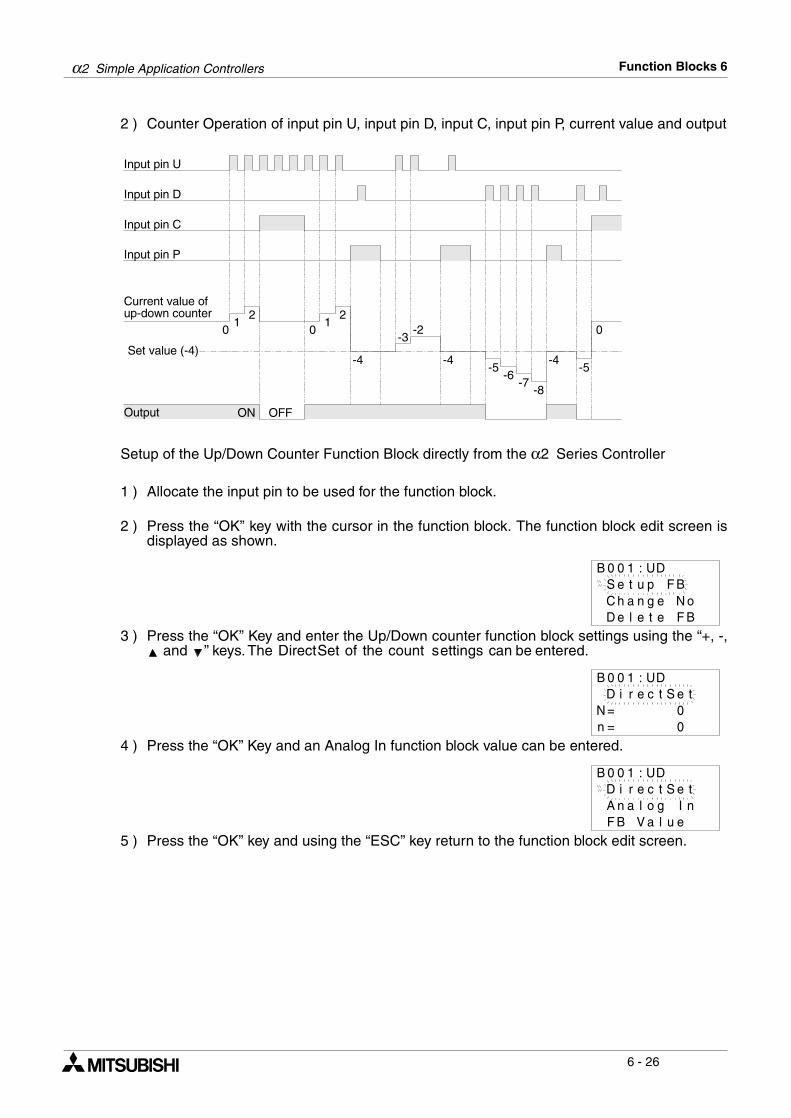
α2 Simple Application Controllers Function Blocks 6
6 - 26
2 ) Counter Operation of input pin U, input pin D, input C, input pin P, current value and output
Setup of the Up/Down Counter Function Block directly from the α2 Series Controller
1 ) Allocate the input pin to be used for the function block.
2 ) Press the “OK” key with the cursor in the function block. The function block edit screen isdisplayed as shown.
3 ) Press the “OK” Key and enter the Up/Down counter function block settings using the “+, -, and ” keys. The Direct Set of the count s ettings can be entered.
4 ) Press the “OK” Key and an Analog In function block value can be entered.
5 ) Press the “OK” key and using the “ESC” key return to the function block edit screen.
Input pin U
Input pin D
Current value ofup-down counter
01
2
-3-2
-4-5
Set value (-4)
Output ON OFF
Input pin C
Input pin P
12
0
-4-6
-7-8
-4-5
0
B 0 0 1 : UD
C h a n g e N oD e l e t e F B
S e t u p F B
D i r eB 0 0 1 : UD
N = 0n = 0
c t S e t
D i r eB 0 0 1 : UD
c t S e tA n a l o g I nF B V a l u e

α2 Simple Application Controllers Function Blocks 6
6 - 27
6.13 Compare Block
The function block compares value 1 (V1) with value 2 (V2) using an operational basedinstruction based upon the following conditions: =, >, >=, <, <= or <>. If current values satisfythe operational expression then the output status is ON.
Table 6.14: Compare Function Block
Setup of the Compare Function Block directly from the α2 Series Controller
1 ) Allocate the input pin to be used for the function block.
2 ) Press the “OK” key with the cursor in the function block. The function block edit screen isdisplayed as shown.
3 ) Press the “OK” Key and enter the function block settings using the “ and ” keys.
4 ) Pressing the “OK” key invokes the menu that lists the function block input data type.
5 ) Press the “OK” Key and a Direct Set value can be entered..
Function Set Item Description
I Input pin for compare operation
FB
The following three set items exist:
1) Compare Value (V1): a) Constant value set range:-32768 to +32767 with an initial value 0 b) Analogue value set range: A01-A08 c) Output value from a different function block
2) Operational Expression: =, >, >=, <, <=, <>
3) Compare Value (V2): a) Constant value set range:-32768 to +32767 with an initial value 0 b) Analogue value set range: A01-A08 c) Output value from a different function block
Output If Compare value (V1) and Compare value (V2) satisfies theoperational expression the status of the output is ON.
0 00
PC
OI P
B 0 0 1 : CPS e t u p F BC h a n g e N oD e l e t e F B
B 0 0 1 : CPCmp V a lV 1 = V 2
0
1
B 0 0 1 : CPD i r e c t SA n a l o g I nF B V a l u e
e t
B 0 0 1 : CPCmp V a l
D i r e c t S e t0
1
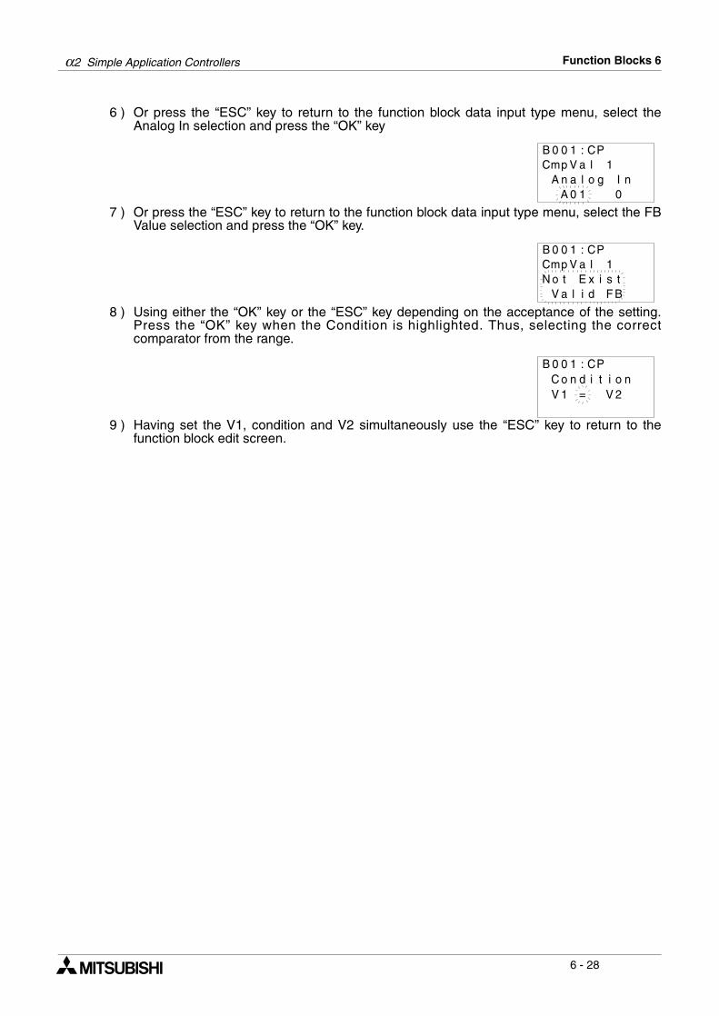
α2 Simple Application Controllers Function Blocks 6
6 - 28
6 ) Or press the “ESC” key to return to the function block data input type menu, select theAnalog In selection and press the “OK” key
7 ) Or press the “ESC” key to return to the function block data input type menu, select the FBValue selection and press the “OK” key.
8 ) Using either the “OK” key or the “ESC” key depending on the acceptance of the setting.Press the “OK” key when the Condition is highlighted. Thus, selecting the correctcomparator from the range.
9 ) Having set the V1, condition and V2 simultaneously use the “ESC” key to return to thefunction block edit screen.
B 0 0 1 : CPCmp V a l
0
1A n a l o g I n
A 0 1
B 0 0 1 : CPCmp V a l 1N o t E x i s t
V a l i d F B
B 0 0 1 : CPC o n d i tV 1 = V 2
i o n
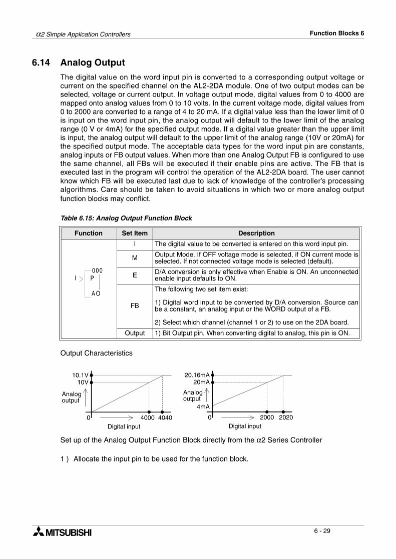
α2 Simple Application Controllers Function Blocks 6
6 - 29
6.14 Analog Output
The digital value on the word input pin is converted to a corresponding output voltage orcurrent on the specified channel on the AL2-2DA module. One of two output modes can beselected, voltage or current output. In voltage output mode, digital values from 0 to 4000 aremapped onto analog values from 0 to 10 volts. In the current voltage mode, digital values from0 to 2000 are converted to a range of 4 to 20 mA. If a digital value less than the lower limit of 0is input on the word input pin, the analog output will default to the lower limit of the analogrange (0 V or 4mA) for the specified output mode. If a digital value greater than the upper limitis input, the analog output will default to the upper limit of the analog range (10V or 20mA) forthe specified output mode. The acceptable data types for the word input pin are constants,analog inputs or FB output values. When more than one Analog Output FB is configured to usethe same channel, all FBs will be executed if their enable pins are active. The FB that isexecuted last in the program will control the operation of the AL2-2DA board. The user cannotknow which FB will be executed last due to lack of knowledge of the controller’s processingalgorithms. Care should be taken to avoid situations in which two or more analog outputfunction blocks may conflict.
Table 6.15: Analog Output Function Block
Output Characteristics
Set up of the Analog Output Function Block directly from the α2 Series Controller
1 ) Allocate the input pin to be used for the function block.
Function Set Item Description
I The digital value to be converted is entered on this word input pin.
M Output Mode. If OFF voltage mode is selected, if ON current mode isselected. If not connected voltage mode is selected (default).
E D/A conversion is only effective when Enable is ON. An unconnectedenable input defaults to ON.
FB
The following two set item exist:
1) Digital word input to be converted by D/A conversion. Source canbe a constant, an analog input or the WORD output of a FB.
2) Select which channel (channel 1 or 2) to use on the 2DA board.
Output 1) Bit Output pin. When converting digital to analog, this pin is ON.
000
A O
I P
Analogoutput
Digital input0 4000
10V
Digital input0 2000
20mA
4mA
Analogoutput
Digital input
10V
0 4000 4040
10.1V
Analogoutput
Digital input
20mA
0 2000 2020
20.16mA
Analogoutput
4mA
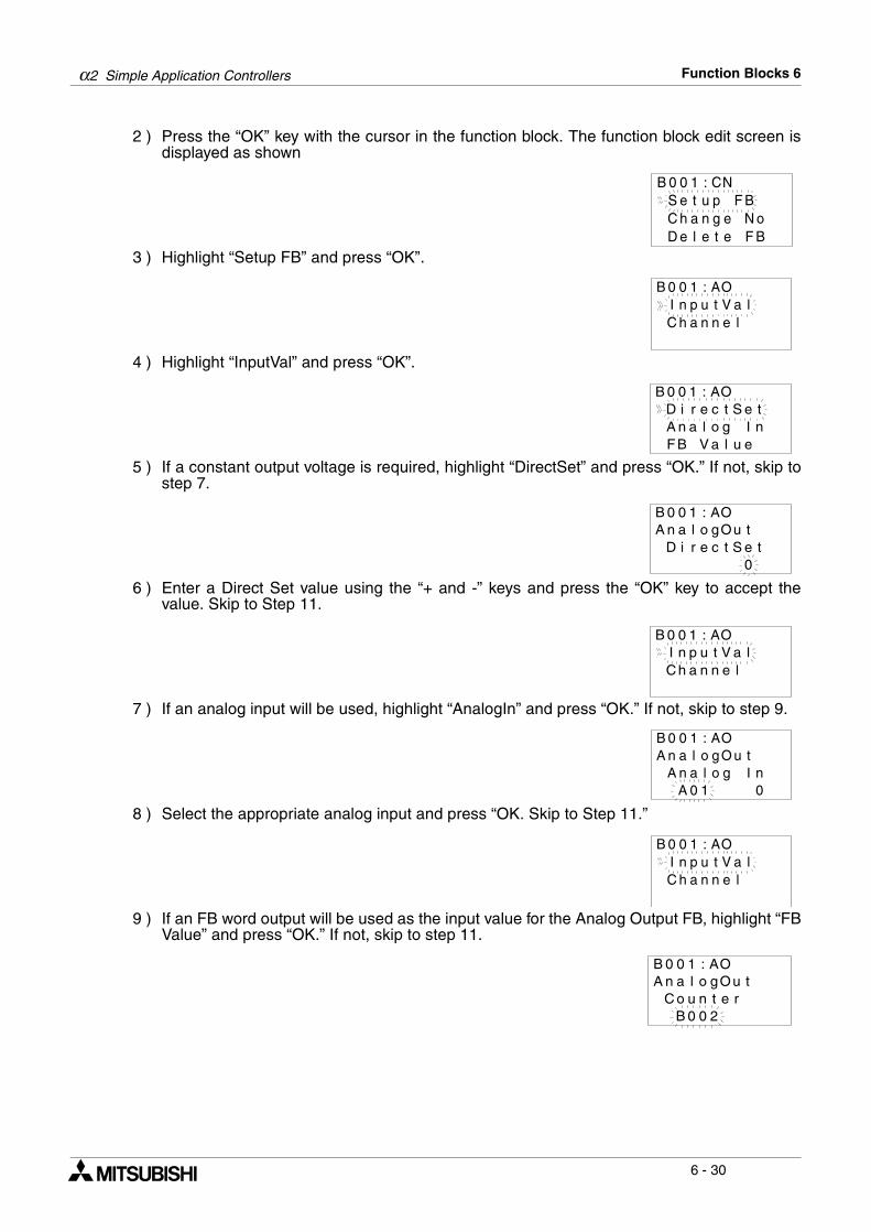
α2 Simple Application Controllers Function Blocks 6
6 - 30
2 ) Press the “OK” key with the cursor in the function block. The function block edit screen isdisplayed as shown
3 ) Highlight “Setup FB” and press “OK”.
4 ) Highlight “InputVal” and press “OK”.
5 ) If a constant output voltage is required, highlight “DirectSet” and press “OK.” If not, skip tostep 7.
6 ) Enter a Direct Set value using the “+ and -” keys and press the “OK” key to accept thevalue. Skip to Step 11.
7 ) If an analog input will be used, highlight “AnalogIn” and press “OK.” If not, skip to step 9.
8 ) Select the appropriate analog input and press “OK. Skip to Step 11.”
9 ) If an FB word output will be used as the input value for the Analog Output FB, highlight “FBValue” and press “OK.” If not, skip to step 11.
B 0 0 1 : CNS e t u p F BC h a n g e N oD e l e t e F B
I n p u t lVC h a n n e l
B 0 0 1 : AOa
D i r e c tSA n a l o g IFB V a l u e
B 0 0 1 : AOet
n
A n a l o tOD i r e c t S
0
B 0 0 1 : AOug
e t
I n p u t lVC h a n n e l
B 0 0 1 : AOa
A n a l o tOA n a l o g I
0
B 0 0 1 : AOug
nA 0 1
I n p u t lVC h a n n e l
B 0 0 1 : AOa
A n a l o tOC o u n t e r
2
B 0 0 1 : AOug
B 0 0
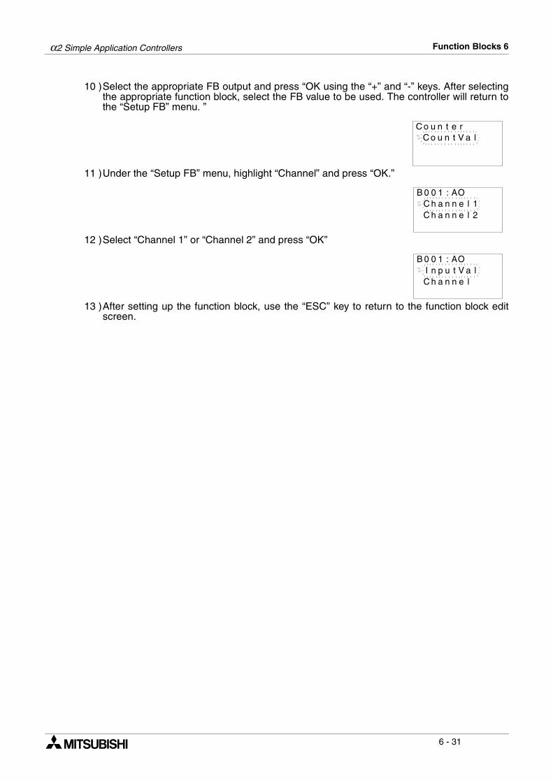
α2 Simple Application Controllers Function Blocks 6
6 - 31
10 )Select the appropriate FB output and press “OK using the “+” and “-” keys. After selectingthe appropriate function block, select the FB value to be used. The controller will return tothe “Setup FB” menu. ”
11 )Under the “Setup FB” menu, highlight “Channel” and press “OK.”
12 )Select “Channel 1” or “Channel 2” and press “OK”
13 )After setting up the function block, use the “ESC” key to return to the function block editscreen.
C o u n t lVC o u n t e r
a
C h a n n 1eC h a n n e l
B 0 0 1 : AOl
2
I n p u t lVC h a n n e l
B 0 0 1 : AOa
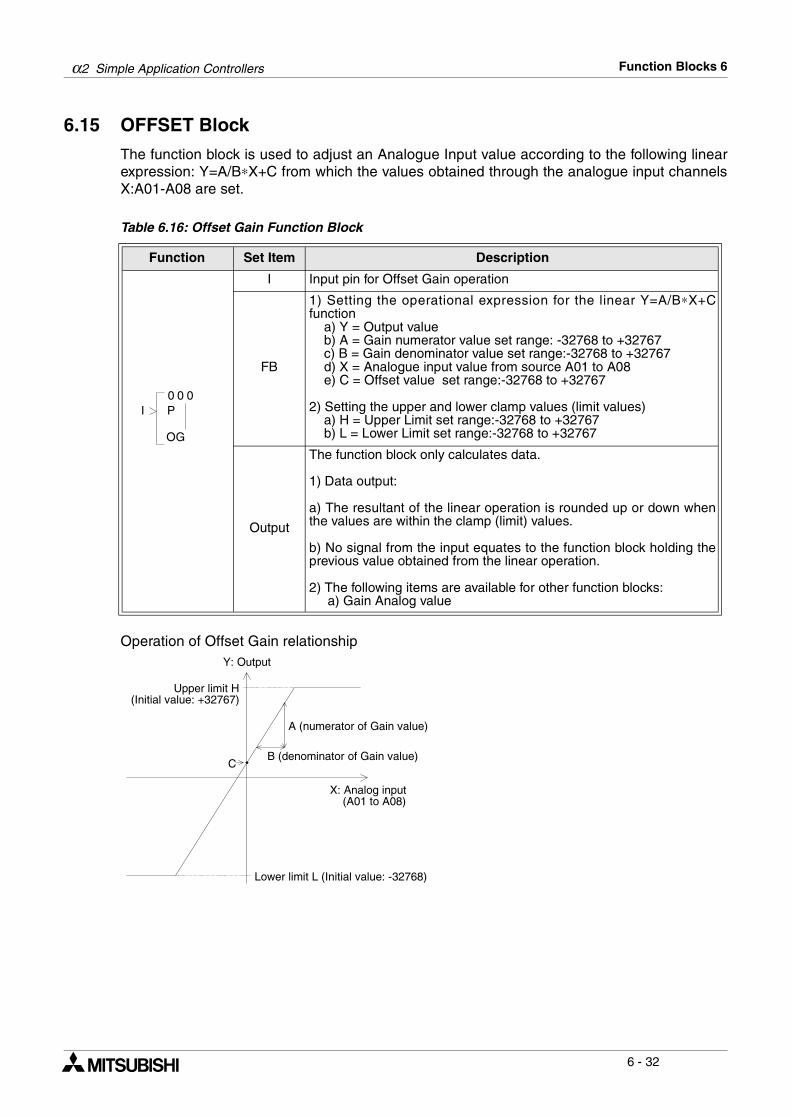
α2 Simple Application Controllers Function Blocks 6
6 - 32
6.15 OFFSET Block
The function block is used to adjust an Analogue Input value according to the following linearexpression: Y=A/B∗X+C from which the values obtained through the analogue input channelsX:A01-A08 are set.
Table 6.16: Offset Gain Function Block
Operation of Offset Gain relationship
Function Set Item Description
I Input pin for Offset Gain operation
FB
1) Setting the operational expression for the linear Y=A/B∗X+Cfunction a) Y = Output value b) A = Gain numerator value set range: -32768 to +32767 c) B = Gain denominator value set range:-32768 to +32767 d) X = Analogue input value from source A01 to A08 e) C = Offset value set range:-32768 to +32767
2) Setting the upper and lower clamp values (limit values) a) H = Upper Limit set range:-32768 to +32767 b) L = Lower Limit set range:-32768 to +32767
Output
The function block only calculates data.
1) Data output: a) The resultant of the linear operation is rounded up or down whenthe values are within the clamp (limit) values. b) No signal from the input equates to the function block holding theprevious value obtained from the linear operation.
2) The following items are available for other function blocks: a) Gain Analog value
0 00
GO
I P
C
A (numerator of Gain value)
B (denominator of Gain value)
X: Analog input (A01 to A08)
Lower limit L (Initial value: -32768)
Upper limit H(Initial value: +32767)
Y: Output
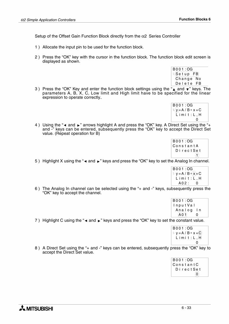
α2 Simple Application Controllers Function Blocks 6
6 - 33
Setup of the Offset Gain Function Block directly from the α2 Series Controller
1 ) Allocate the input pin to be used for the function block.
2 ) Press the “OK” key with the cursor in the function block. The function block edit screen isdisplayed as shown.
3 ) Press the “OK” Key and enter the function block settings using the “ and ” keys. Theparameters A, B, X, C, Low limit and High limit have to be specified for the linearexpression to operate correctly..
4 ) Using the “ and ” arrows highlight A and press the “OK” key. A Direct Set using the “+and -” keys can be entered, subsequently press the “OK” key to accept the Direct Setvalue. (Repeat operation for B)
5 ) Highlight X using the “ and ” keys and press the “OK” key to set the Analog In channel.
6 ) The Analog In channel can be selected using the “+ and -” keys, subsequently press the“OK” key to accept the channel.
7 ) Highlight C using the “ and ” keys and press the “OK” key to set the constant value.
8 ) A Direct Set using the “+ and -” keys can be entered, subsequently press the “OK” key toaccept the Direct Set value.
B 0 0 1 : OGS e t u p F BC h a n g e N oD e l e t e F B
B 0 0 1 : OGy = A / B ∗ xL i m i t : L ,
+ CH
0
B 0 0 1 : OGC o n s t a n
D i r e c t S et A
t1
B 0 0 1 : OGy = A / B ∗ xL i m i t : L ,
+ CH
0A 0 2 :
B 0 0 1 : OGI n p u t V a
A n a l o g Il
nA 0 1 0
B 0 0 1 : OGy = A / B ∗ xL i m i t : L ,
+ CH
0
B 0 0 1 : OGC o n s t a n
D i r e c t S et C
t0
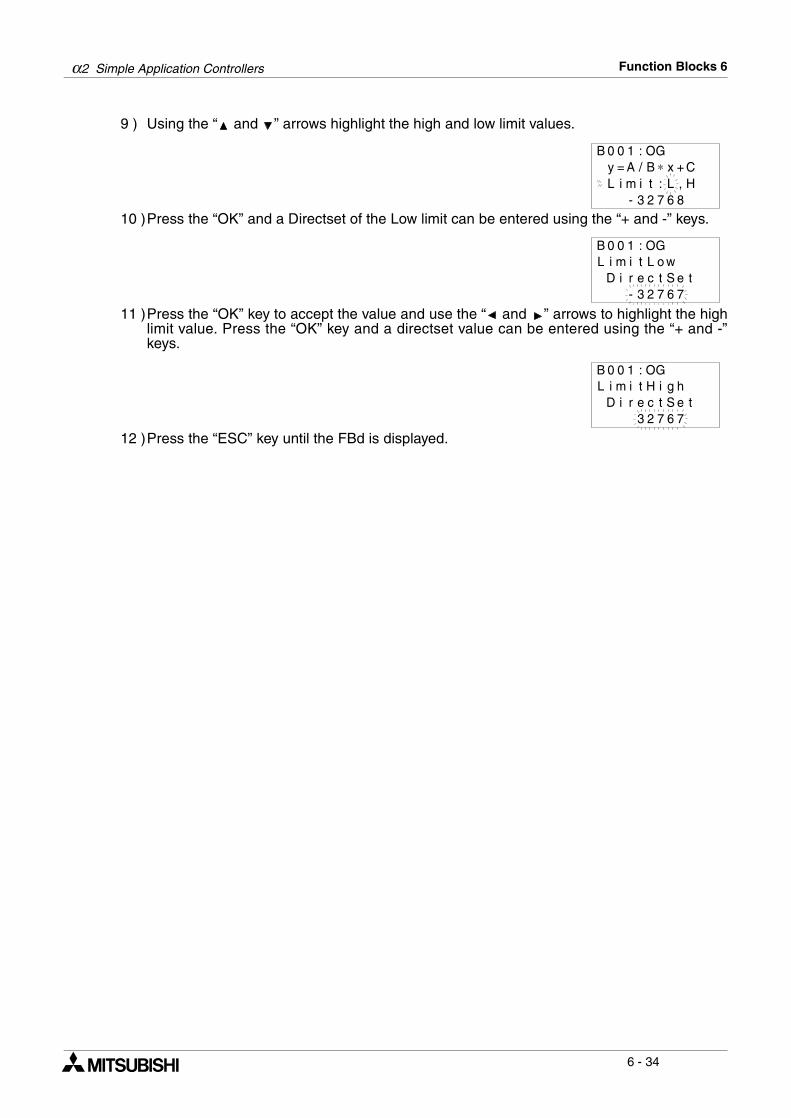
α2 Simple Application Controllers Function Blocks 6
6 - 34
9 ) Using the “ and ” arrows highlight the high and low limit values.
10 )Press the “OK” and a Directset of the Low limit can be entered using the “+ and -” keys.
11 )Press the “OK” key to accept the value and use the “ and ” arrows to highlight the highlimit value. Press the “OK” key and a directset value can be entered using the “+ and -”keys.
12 )Press the “ESC” key until the FBd is displayed.
B 0 0 1 : OGy = A / B ∗ xL i m i t : L ,
+ CH
6 82 7- 3
B 0 0 1 : OGL i m i L o w
D i r e c t S e t6 72 73-
t
B 0 0 1 : OGL i m i H i g
D i r e c t S e t6 72 73
ht
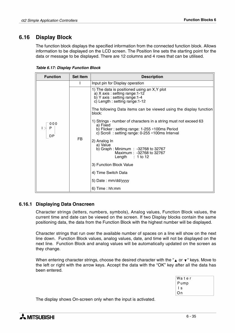
α2 Simple Application Controllers Function Blocks 6
6 - 35
6.16 Display Block
The function block displays the specified information from the connected function block. Allowsinformation to be displayed on the LCD screen. The Position line sets the starting point for thedata or message to be displayed. There are 12 columns and 4 rows that can be utilised.
Table 6.17: Display Function Block
6.16.1 Displaying Data Onscreen
Character strings (letters, numbers, symbols), Analog values, Function Block values, thecurrent time and date can be viewed on the screen. If two Display blocks contain the samepositioning data, the data from the Function Block with the highest number will be displayed.
Character strings that run over the available number of spaces on a line will show on the nextline down. Function Block values, analog values, date, and time will not be displayed on thenext line. Function Block and analog values will be automatically updated on the screen asthey change.
When entering character strings, choose the desired character with the “ or “ keys. Move tothe left or right with the arrow keys. Accept the data with the “OK” key after all the data hasbeen entered.
The display shows On-screen only when the input is activated.
Function Set Item Description
I Input pin for Display operation
FB
1) The data is positioned using an X,Y plot a) X axis : setting range:1-12 b) Y axis : setting range:1-4 c) Length : setting range:1-12
The following Data items can be viewed using the display functionblock: 1) Strings - number of characters in a string must not exceed 63 a) Fixed b) Flicker : setting range: 1-255 ∗100ms Period c) Scroll : setting range: 0-255 ∗100ms Interval
2) Analog In a) Value b) Graph : Minimum : -32768 to 32767 Maximum : -32768 to 32767 Length : 1 to 12
3) Function Block Value
4) Time Switch Data
5) Date : mm/dd/yyyy
6) Time : hh:mm
0 00
PD
I P
reaWpuP m
nO
t
I s
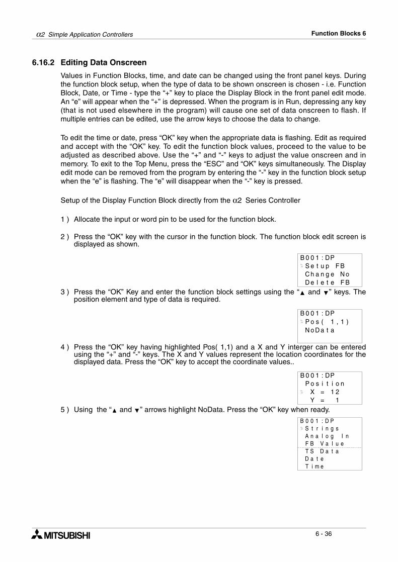
α2 Simple Application Controllers Function Blocks 6
6 - 36
6.16.2 Editing Data Onscreen
Values in Function Blocks, time, and date can be changed using the front panel keys. Duringthe function block setup, when the type of data to be shown onscreen is chosen - i.e. FunctionBlock, Date, or Time - type the “+” key to place the Display Block in the front panel edit mode.An “e” will appear when the “+” is depressed. When the program is in Run, depressing any key(that is not used elsewhere in the program) will cause one set of data onscreen to flash. Ifmultiple entries can be edited, use the arrow keys to choose the data to change.
To edit the time or date, press “OK” key when the appropriate data is flashing. Edit as requiredand accept with the “OK” key. To edit the function block values, proceed to the value to beadjusted as described above. Use the “+” and “-” keys to adjust the value onscreen and inmemory. To exit to the Top Menu, press the “ESC” and “OK” keys simultaneously. The Displayedit mode can be removed from the program by entering the “-” key in the function block setupwhen the “e” is flashing. The “e” will disappear when the “-” key is pressed.
Setup of the Display Function Block directly from the α2 Series Controller
1 ) Allocate the input or word pin to be used for the function block.
2 ) Press the “OK” key with the cursor in the function block. The function block edit screen isdisplayed as shown.
3 ) Press the “OK” Key and enter the function block settings using the “ and ” keys. Theposition element and type of data is required.
4 ) Press the “OK” key having highlighted Pos( 1,1) and a X and Y interger can be enteredusing the “+” and “-” keys. The X and Y values represent the location coordinates for thedisplayed data. Press the “OK” key to accept the coordinate values..
5 ) Using the “ and ” arrows highlight NoData. Press the “OK” key when ready.
B 0 0 1 : D
C h a n g e N oD e l e t e F B
PS e t u p F B
P o s ( 1 1, )B 0 0 1 : DP
N o D a at
P o s i i noB 0 0 1 : DP
X = 21t
Y = 1
S t r i g sB 0 0 1 : D P
A n l o Ign
nF B V ua elT S D aa tD ea tT ei m
a
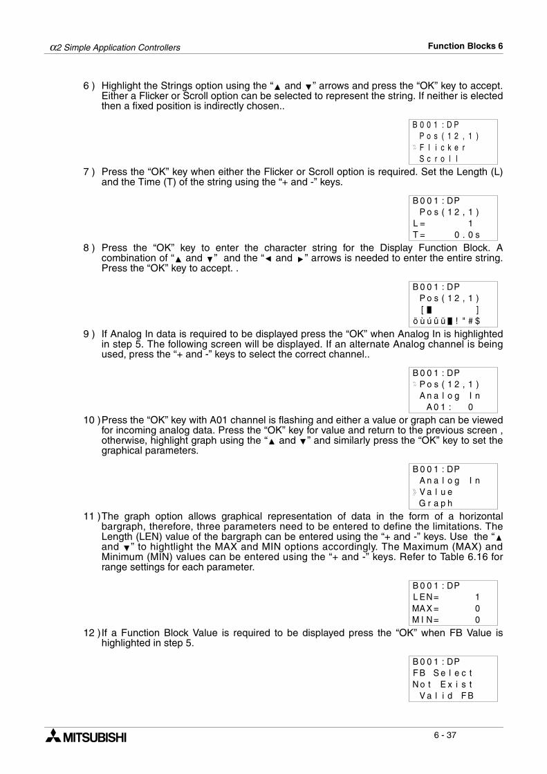
α2 Simple Application Controllers Function Blocks 6
6 - 37
6 ) Highlight the Strings option using the “ and ” arrows and press the “OK” key to accept.Either a Flicker or Scroll option can be selected to represent the string. If neither is electedthen a fixed position is indirectly chosen..
7 ) Press the “OK” key when either the Flicker or Scroll option is required. Set the Length (L)and the Time (T) of the string using the “+ and -” keys.
8 ) Press the “OK” key to enter the character string for the Display Function Block. Acombination of “ and ” and the “ and ” arrows is needed to enter the entire string.Press the “OK” key to accept. .
9 ) If Analog In data is required to be displayed press the “OK” when Analog In is highlightedin step 5. The following screen will be displayed. If an alternate Analog channel is beingused, press the “+ and -” keys to select the correct channel..
10 )Press the “OK” key with A01 channel is flashing and either a value or graph can be viewedfor incoming analog data. Press the “OK” key for value and return to the previous screen ,otherwise, highlight graph using the “ and ” and similarly press the “OK” key to set thegraphical parameters.
11 )The graph option allows graphical representation of data in the form of a horizontalbargraph, therefore, three parameters need to be entered to define the limitations. TheLength (LEN) value of the bargraph can be entered using the “+ and -” keys. Use the “and ” to hightlight the MAX and MIN options accordingly. The Maximum (MAX) andMinimum (MIN) values can be entered using the “+ and -” keys. Refer to Table 6.16 forrange settings for each parameter.
12 )If a Function Block Value is required to be displayed press the “OK” when FB Value ishighlighted in step 5.
B 0 0 1 : D PP o s ( 2 1, )1F l i c e rkS c r o ll
B 0 0 1 : DPP o s ( 2 1, )1= 1L=T 0 0. s
B 0 0 1 : DPP o s ( 2 1, )1[ ]ù ú û "! #üö $
B 0 0 1 : DPP o s ( 2 1, )1A n a l go
A 0 1 0:I n
B 0 0 1 : DP
V a l u eG r a p h
A n a l go I n
B 0 0 1 : DPL EN= 1MA X = 0M I N= 0
B 0 0 1 : DP
N o tV a l i d
F B S le c texE s ti
F B
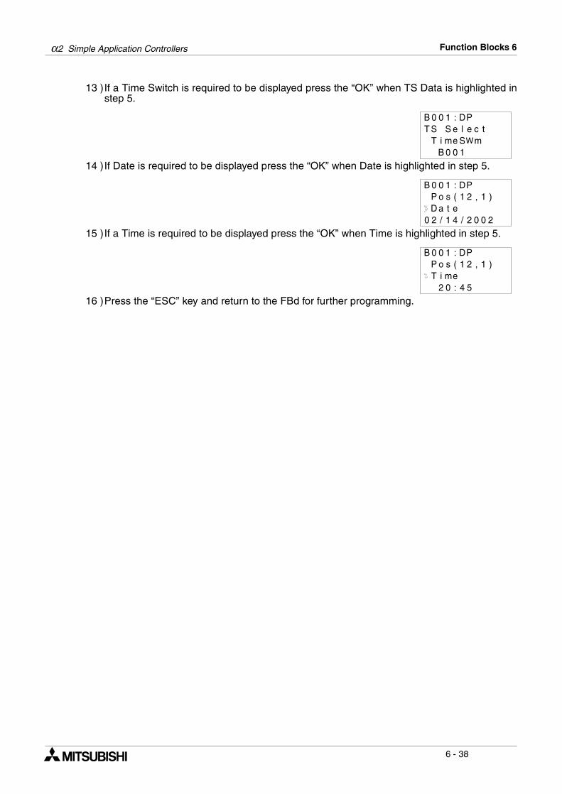
α2 Simple Application Controllers Function Blocks 6
6 - 38
13 )If a Time Switch is required to be displayed press the “OK” when TS Data is highlighted instep 5.
14 )If Date is required to be displayed press the “OK” when Date is highlighted in step 5.
15 )If a Time is required to be displayed press the “OK” when Time is highlighted in step 5.
16 )Press the “ESC” key and return to the FBd for further programming.
B 0 0 1 : DPS S e e tclT i me WS m
T
B 0 0 1
B 0 0 1 : DPP o s ( 2 1, )1D a t e2 / 1 40 2 0 0 2/
B 0 0 1 : DPP o s ( 2 1, )1T i me
2 0 : 4 5
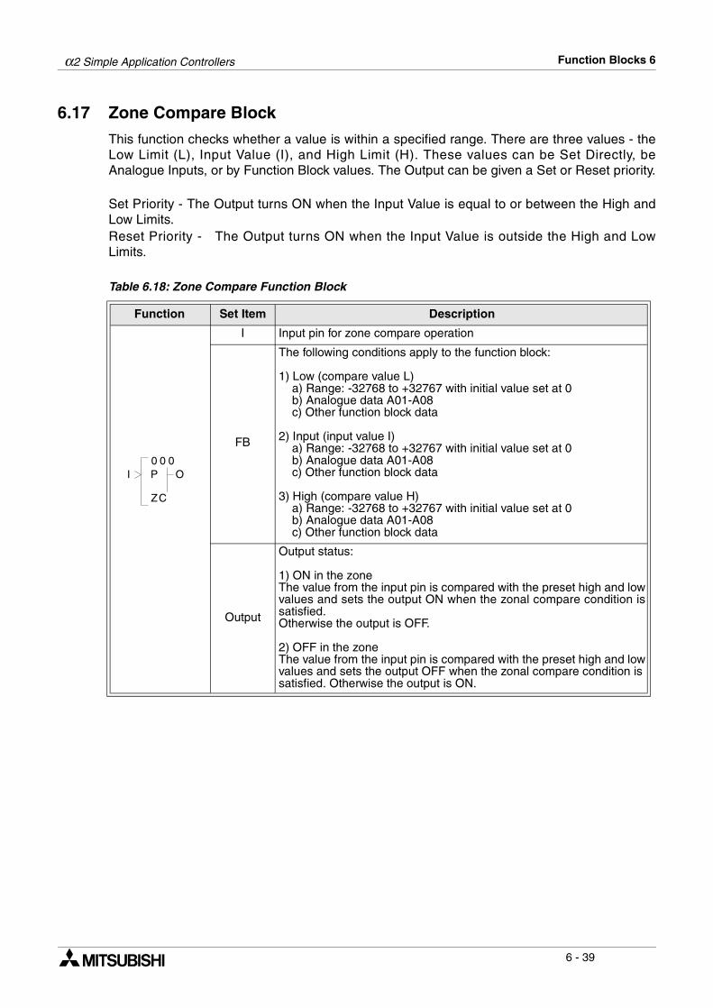
α2 Simple Application Controllers Function Blocks 6
6 - 39
6.17 Zone Compare Block
This function checks whether a value is within a specified range. There are three values - theLow Limit (L), Input Value (I), and High Limit (H). These values can be Set Directly, beAnalogue Inputs, or by Function Block values. The Output can be given a Set or Reset priority.
Set Priority - The Output turns ON when the Input Value is equal to or between the High andLow Limits. Reset Priority - The Output turns ON when the Input Value is outside the High and LowLimits.
Table 6.18: Zone Compare Function Block
Function Set Item Description
I Input pin for zone compare operation
FB
The following conditions apply to the function block:
1) Low (compare value L) a) Range: -32768 to +32767 with initial value set at 0 b) Analogue data A01-A08 c) Other function block data
2) Input (input value I) a) Range: -32768 to +32767 with initial value set at 0 b) Analogue data A01-A08 c) Other function block data
3) High (compare value H) a) Range: -32768 to +32767 with initial value set at 0 b) Analogue data A01-A08 c) Other function block data
Output
Output status:
1) ON in the zoneThe value from the input pin is compared with the preset high and lowvalues and sets the output ON when the zonal compare condition issatisfied.Otherwise the output is OFF.
2) OFF in the zoneThe value from the input pin is compared with the preset high and lowvalues and sets the output OFF when the zonal compare condition issatisfied. Otherwise the output is ON.
0 00
CZ
OI P
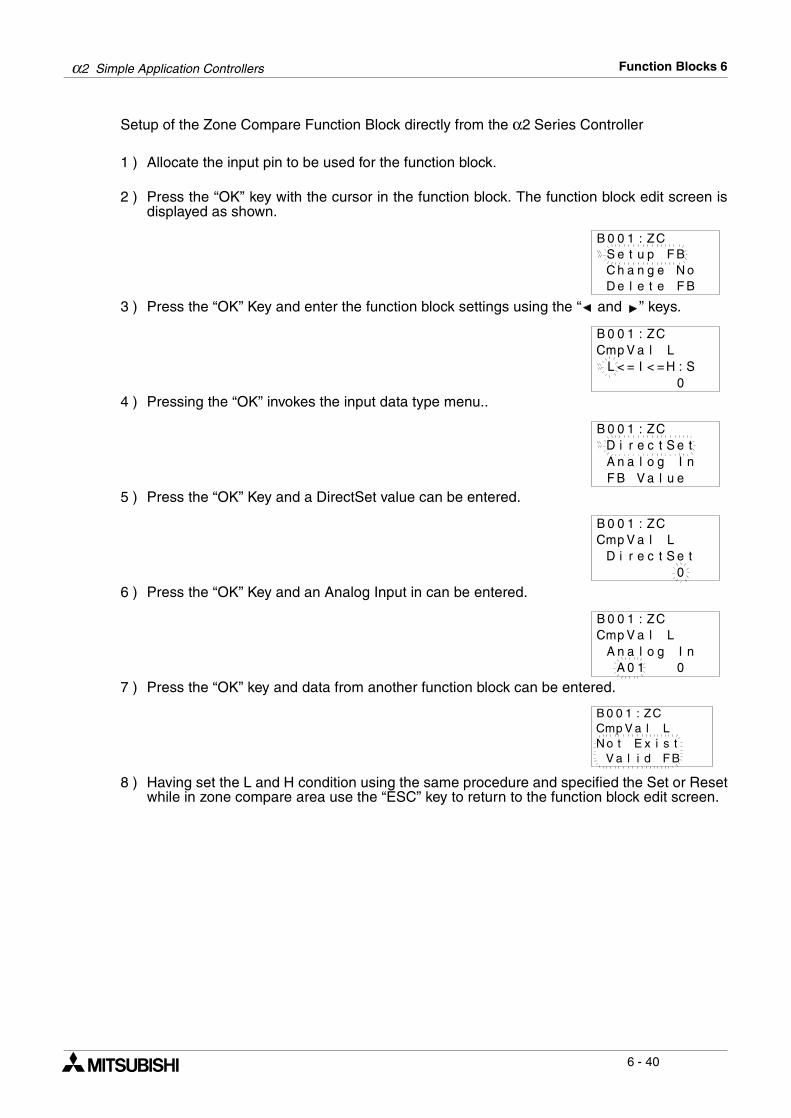
α2 Simple Application Controllers Function Blocks 6
6 - 40
Setup of the Zone Compare Function Block directly from the α2 Series Controller
1 ) Allocate the input pin to be used for the function block.
2 ) Press the “OK” key with the cursor in the function block. The function block edit screen isdisplayed as shown.
3 ) Press the “OK” Key and enter the function block settings using the “ and ” keys.
4 ) Pressing the “OK” invokes the input data type menu..
5 ) Press the “OK” Key and a DirectSet value can be entered.
6 ) Press the “OK” Key and an Analog Input in can be entered.
7 ) Press the “OK” key and data from another function block can be entered.
8 ) Having set the L and H condition using the same procedure and specified the Set or Resetwhile in zone compare area use the “ESC” key to return to the function block edit screen.
C h a n g e N oD e l e t e F B
B 0 0 1 : ZCS e t u p F B
Cmp V a l LB 0 0 1 : ZC
L < = I < = H : S0
D i r e c t SB 0 0 1 : ZC
e tA n a l o g I nF B V a l u e
0
B 0 0 1 : ZCCmp V a l L
D i r e c t S e t
B 0 0 1 : ZC
A 0 1 0
Cmp V a l LA n a l o g I n
B 0 0 1 : ZCCmp V a l LN o t E x i s t
V a l i d F B
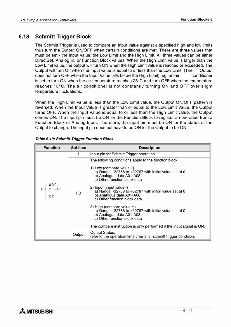
α2 Simple Application Controllers Function Blocks 6
6 - 41
6.18 Schmitt Trigger Block
The Schmitt Trigger is used to compare an Input value against a specified high and low limitsthus turn the Output ON/OFF when certain conditions are met. There are three values thatmust be set - the Input Value, the Low Limit and the High Limit. All three values can be eitherDirectSet, Analog In, or Function Block values. When the High Limit value is larger than theLow Limit value, the output will turn ON when the High Limit value is reached or exceeded. TheOutput will turn Off when the Input value is equal to or less than the Low Limit. (The Outputdoes not turn OFF when the Input Value falls below the High Limit), eg. an air conditioneris set to turn ON when the air temperature reaches 23°C and turn OFF when the temperaturereaches 18°C. The air conditioner is not constantly turning ON and OFF over slighttemperature fluctuations.
When the High Limit value is less than the Low Limit value, the Output ON/OFF pattern isreversed. When the Input Value is greater than or equal to the Low Limit Value, the Outputturns OFF. When the Input Value is equal to or less than the High Limit value, the Outputcomes ON. The input pin must be ON for the Function Block to register a new value from aFunction Block or Analog Input. Therefore, the input pin must be ON for the status of theOutput to change. The input pin does not have to be ON for the Output to be ON.
Table 6.19: Schmitt Trigger Function Block
Function Set Item Description
I Input pin for Schmitt Trigger operation
FB
The following conditions apply to the function block:
1) Low (compare value L) a) Range: -32768 to +32767 with initial value set at 0 b) Analogue data A01-A08 c) Other function block data
2) Input (input value I) a) Range: -32768 to +32767 with initial value set at 0 b) Analogue data A01-A08 c) Other function block data
3) High (compare value H) a) Range: -32768 to +32767 with initial value set at 0 b) Analogue data A01-A08 c) Other function block data
The compare instruction is only performed if the input signal is ON.
Output Output Status:refer to the operation time charts for schmitt trigger condition.
0 00
TS
OI P
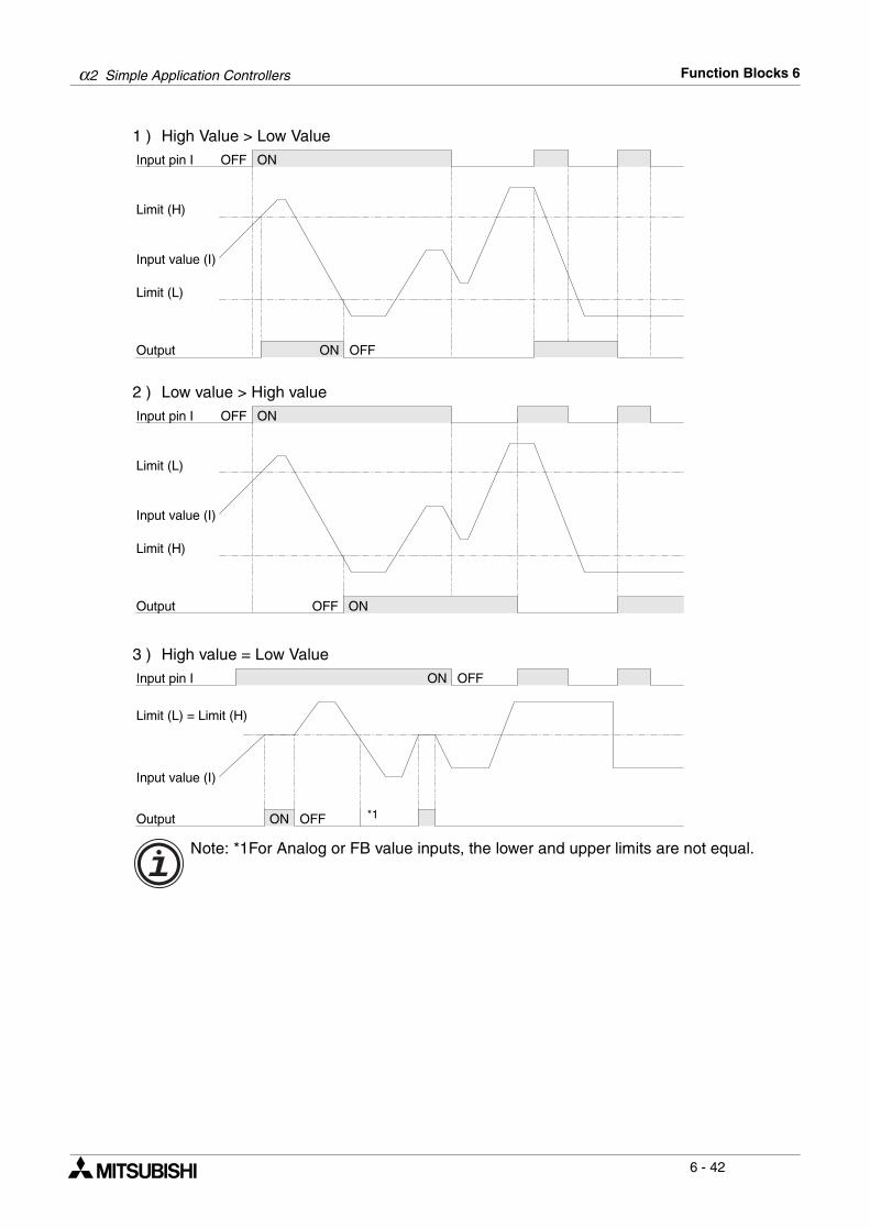
α2 Simple Application Controllers Function Blocks 6
6 - 42
1 ) High Value > Low Value
2 ) Low value > High value
3 ) High value = Low Value
Note: *1For Analog or FB value inputs, the lower and upper limits are not equal.
Input pin I
Limit (H)
Output
Limit (L)
Input value (I)
ON OFF
ONOFF
Input pin I
Limit (L)
Output
Limit (H)
Input value (I)
ONOFF
ONOFF
Input pin I
Limit (L) = Limit (H)
Output
Input value (I)
ON OFF
ON OFF *1
α2 Simple Application Controllers Function Blocks 6
6 - 43
Setup of the Schmitt Trigger Function Block directly from the α2 Series Controller
1 ) Allocate the input pin to be used for the function block.
2 ) Press the “OK” key with the cursor in the function block. The function block edit screen isdisplayed as shown.
3 ) Press the “OK” Key and enter the function block settings using the “ and ” keys.
4 ) Press the “OK” key with the InputVal highlighted and the user can enter a the appropriateInput Val data from either a DirectSet, Analog In or other FB Values.
5 ) The Low and High limit can be given Input Val data from either a DirectSet, Analog In orother FB Values. Press the “ESC” key to return the edit screen for the function block andthe user can change the low or high limits either by DirectSet, Analog In or FB Value.
C h a n g e N oD e l e t e F B
B 0 0 1 : S TS e t u p F B
I n p u t V lB 0 0 1 : S T
L i m i t = L , H0
a
D i r e c t SB 0 0 1 : S T
e tA n a l o g I nF B V a l u e
α2 Simple Application Controllers Function Blocks 6
6 - 44
6.19 Hour Meter Block
The Hour Meter is used to track the amount of time that a device has been in operation. Thiscan be very useful for preventative maintenance schedules or for performing feasibility studies.The timing starts at the receipt of an Input signal and retains the accumulated time throughsystem shutdowns or power failures. When the Set Time value is reached, the block Output willturn ON. The Hour Meter will continue recording time after the Output time is reached. A signalto the Clear pin will reset the current time value to zero.
Table 6.20: Hour Meter Function Block
1 ) Hour operation time chart
Function Set Item Description
I Input pin for hour meter operation
C Clear pin for function block
FB
1) Time units are either hh:mm or mm:ss
2) Time setting range: a) 0-32767 hours with initial value 0 b) 0 - 59 minutes with initial value 0 c) 0 - 59 seconds with initial value 0
Output
1) The output is turned ON after the set time has elapsed.
2) The function block retains the previous value if there is no signalfrom the input pin and restarts with this value when the input is givena signal again.
3) The current time value is reset if the clear pin receives a signal.
4) The following items are available for other function blocks: a) Set Hour b) Current Hour a) Set Minute b) Current Minute
0 00
MH
OIC
P
Input pin I
Input pin C
Output
Starttimekeeping
Suspendtimekeeping
Restarttimekeeping
Starttimekeeping
Starttimekeeping
Restarttimekeeping
Suspendtimekeeping
Timekeeping
Suspendingtimekeeping
Timekeeping
Correspondswith set time
Current value
α2 Simple Application Controllers Function Blocks 6
6 - 45
Setup of the Hour Meter Function Block directly from the α2 Series Controller
1 ) Allocate the input pin to be used for the function block.
2 ) Press the “OK” key with the cursor in the function block. The function block edit screen isdisplayed as shown.
3 ) Press the “OK” key to set the Time unit for the delayed output.
4 ) Press the “OK” key having selected the correct time unit and return to the function blockedit screen. Using the “ and ” keys highlight the Setup FB and press the “OK” key.
5 ) Press the “OK” key with Hour highlighted and using the “ , , + and -” Keys enter the totalhour time for the specified block.
6 ) Press the “OK” key with Minute highlighted and using the “ , , + and -” Keys enter thetotal minute time for the specified block.
T i meS e t u p F B
B 0 0 1 : HMu n i t
C h a n g e N oD e l e t e F B
h h : mm
T i me u n i
mm : s s
t
H o u rB 0 0 1 : HM
M i n u t e
H o u rB 0 0 1 : HM
T = 1 ht = 0 h
M i n uB 0 0 1 : HM
T = 0mt = 0m
t e
α2 Simple Application Controllers Function Blocks 6
6 - 46
6.20 Speed Detect Block
The function block measures the signal input frequency for a set user defined period of time.The frequency is constantly compared to a preset high and low threshold values and theoutput is set ON if the conditions are satisfied. The speed detect function block is used to countincoming pulses, however, for normal inputs without the AL2-4EX expansion moduleconnected the incoming pulses are restricted to 20Hz. The AL2-4EX, with inputs EI1 or EI2,expansion module allows for 1KHz incoming pulses to be measured.
Table 6.21: Speed Detect Function Block
Note: The Speed Detect function (SPD) block can use only 1 high speed frequency(Max.1kHz) in any one program. Subsequent SPD function blocks can only use amaximum of 20Hz for high speeding counting.
Function Set Item Description
I Input pin for speed detect function block
U Count incoming signal
C Clear pin for function block
FB
The function block counts incoming pulses when the input is ON.When the input signal is OFF, the actions to count the pulses of thecounter input and compare the speed with upper and lower thresholdlimit will stop.
1) Speed and output values will not be cleared unless the clear pinreceives a signal to reset the counter.
2) Upper limit> Lower limit:The output signal will be OFF when the speed output value is equal toor less than the lower limit value. If the speed output value is equal toor larger than the upper limit value the output status will be ON.Otherwise the output signal does not change.
3) Lower limit > Upper limitThe output signal will be OFF when the speed output value is equal toor larger than the lower limit value. If the speed output value is equalto or less than the upper limit value the output status will be ON.Otherwise the output signal does not change.
4) Lower limit = Higher limitThe output status is ON if the Speed Output = Lower limit = Upperlimit. Otherwise the output signal is OFF.
5) Function Block data: a) Period setting value: 1 to 32767
Output
Output status:refer to the speed detect time charts for output status.
1) The following items are available for other function blocks: a) Set Period b) Current Period
0 00
PS
OUC
I
D
P
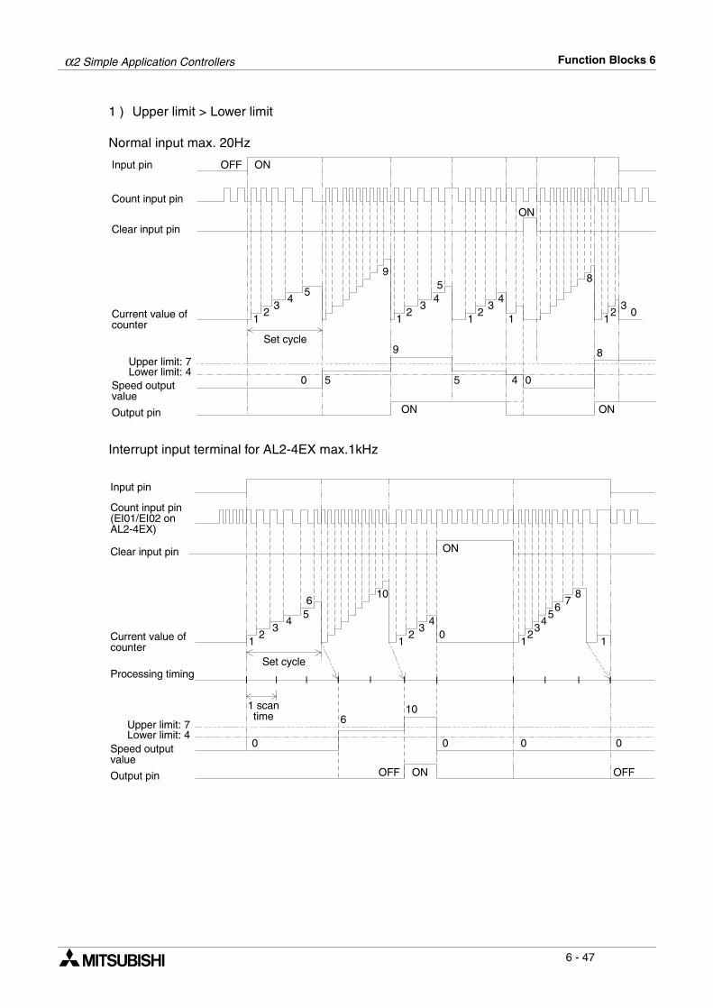
α2 Simple Application Controllers Function Blocks 6
6 - 47
1 ) Upper limit > Lower limit
Normal input max. 20Hz
Interrupt input terminal for AL2-4EX max.1kHz
Clear input pin
Input pin
Count input pin
Current value ofcounter
Upper limit: 7Lower limit: 4
Speed outputvalue
Output pin
OFF ON
ON
12
34
5
9
12
345
12
34
1
8
12
30
8
045
9
50
ONON
Set cycle
Clear input pin
Input pin
Count input pin(EI01/EI02 onAL2-4EX)
Current value ofcounter
Speed outputvalue
Output pin
ON
12
34
5
10
12
34
0
8
1
000
106
0
ONOFF
6
Set cycle
76
54
32
1
OFF
1 scantime
Processing timing
Upper limit: 7Lower limit: 4
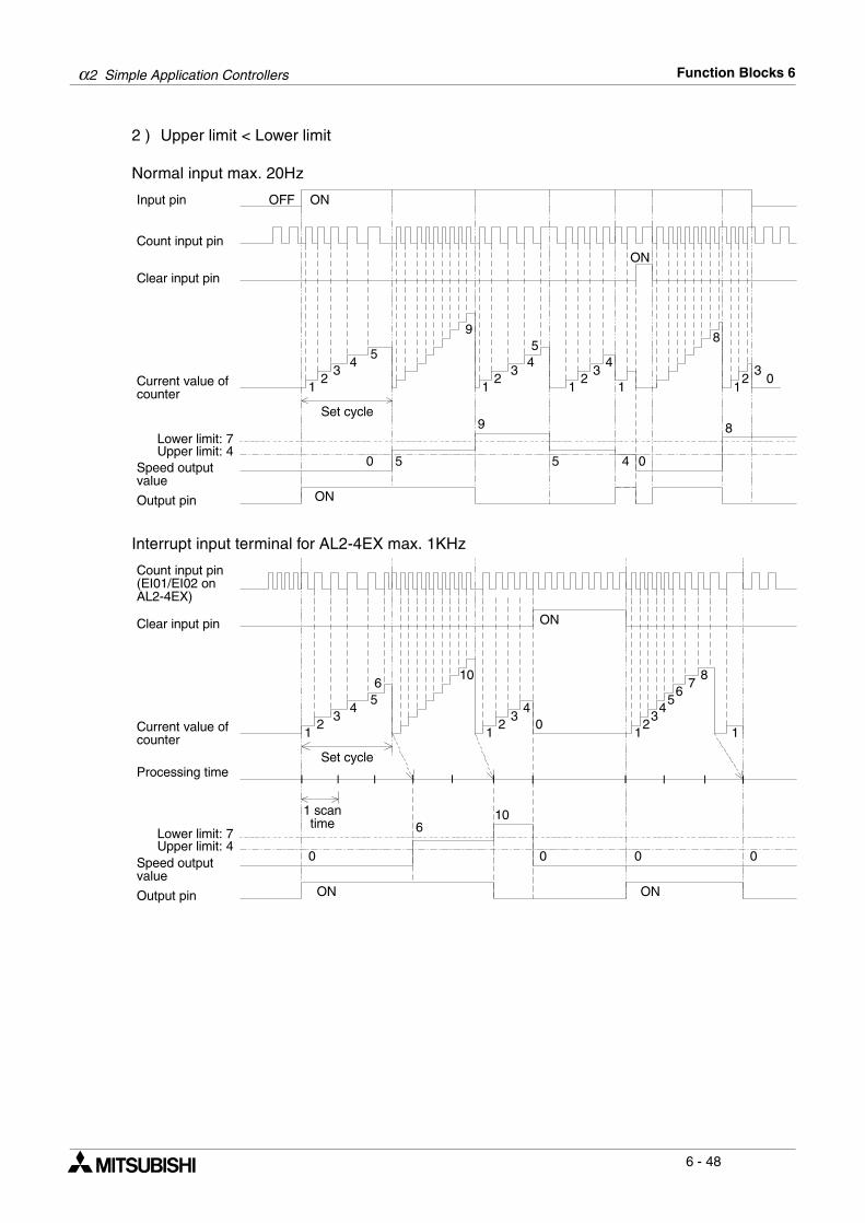
α2 Simple Application Controllers Function Blocks 6
6 - 48
2 ) Upper limit < Lower limit
Normal input max. 20Hz
Interrupt input terminal for AL2-4EX max. 1KHz
Clear input pin
Input pin
Count input pin
Current value ofcounter
Lower limit: 7Upper limit: 4
Speed outputvalue
Output pin
OFF ON
ON
12
34
5
9
12
345
12
34
1
8
12
30
8
045
9
50
Set cycle
ON
Clear input pin
Count input pin(EI01/EI02 onAL2-4EX)
Current value ofcounter
Speed outputvalue
Output pin
ON
12
34
5
10
12
34
0
8
1
000
106
0
ON
6
Set cycle
76
54
32
1
1 scantime
Processing time
Lower limit: 7Upper limit: 4
ON

α2 Simple Application Controllers Function Blocks 6
6 - 49
3 ) Upper limit = Lower limit
Normal input max. 20Hz
Interrupt input terminal for AL2-4EX max 1KHz
Clear input pin
Input pin
Count input pin
Current value ofcounter
Upper limit: 5Lower limit: 5
Speed outputvalue
Output pin
OFF ON
ON
12
34
5
9
12
345
12
34
1
8
12
30
8
045
9
50
ON
Set cycle
Clear input pin
Count input pin(EI01/EI02 onAL2-4EX)
Current value ofcounter
Speed outputvalue
Output pin
ON
12
34
5
10
12
34
0
8
1
000
106
0
ON
6
Set cycle
76
54
32
1
1 scantime
Processing time
Upper limit: 6Lower limit: 6
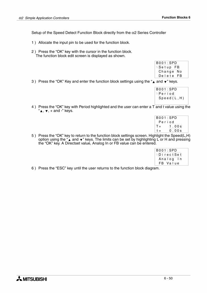
α2 Simple Application Controllers Function Blocks 6
6 - 50
Setup of the Speed Detect Function Block directly from the α2 Series Controller
1 ) Allocate the input pin to be used for the function block.
2 ) Press the “OK” key with the cursor in the function block. The function block edit screen is displayed as shown.
3 ) Press the “OK” Key and enter the function block settings using the “ and ” keys.
4 ) Press the “OK” key with Period highlighted and the user can enter a T and t value using the“ , , + and -” keys.
5 ) Press the “OK” key to return to the function block settings screen. Highlight the Speed(L,H)option using the “ and ” keys. The limits can be set by highlighting L or H and pressingthe “OK” key. A Directset value, Analog In or FB value can be entered.
6 ) Press the “ESC” key until the user returns to the function block diagram.
B 0 0 1 : SP
C h a n g e N oD e l e t e F B
DS e t u p F B
P e r i o dB 0 0 1 : SP
S p e e d ( L ,
D
H )
P e r iB 0 0 1 : SP
T = st = s
o d00
00
.
.10
D
B 0 0 1 : SPDD i r e c t S e tA n a l o g I nF B V a l u e
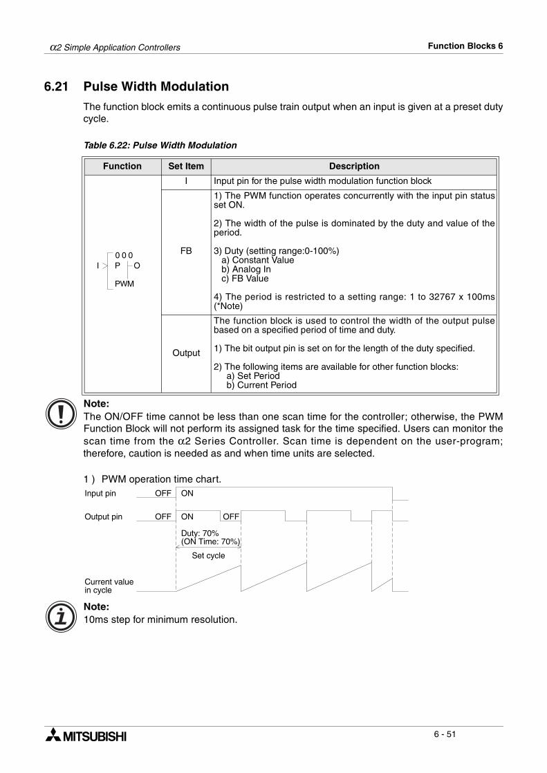
α2 Simple Application Controllers Function Blocks 6
6 - 51
6.21 Pulse Width Modulation
The function block emits a continuous pulse train output when an input is given at a preset dutycycle. Table 6.22: Pulse Width Modulation
Note:The ON/OFF time cannot be less than one scan time for the controller; otherwise, the PWMFunction Block will not perform its assigned task for the time specified. Users can monitor thescan time from the α2 Series Controller. Scan time is dependent on the user-program;therefore, caution is needed as and when time units are selected.
1 ) PWM operation time chart.
Note:10ms step for minimum resolution.
Function Set Item Description
I Input pin for the pulse width modulation function block
FB
1) The PWM function operates concurrently with the input pin statusset ON.
2) The width of the pulse is dominated by the duty and value of theperiod.
3) Duty (setting range:0-100%) a) Constant Value b) Analog In c) FB Value
4) The period is restricted to a setting range: 1 to 32767 x 100ms(*Note)
Output
The function block is used to control the width of the output pulsebased on a specified period of time and duty.
1) The bit output pin is set on for the length of the duty specified.
2) The following items are available for other function blocks: a) Set Period b) Current Period
0 00
WP
OI
M
P
Input pin OFF ON
Output pin OFF ON OFF
Duty: 70%(ON Time: 70%)
Set cycle
Current valuein cycle
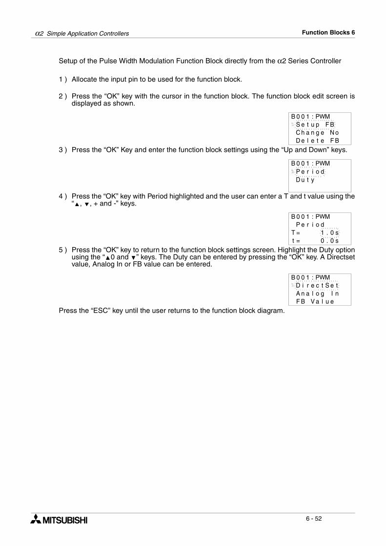
α2 Simple Application Controllers Function Blocks 6
6 - 52
Setup of the Pulse Width Modulation Function Block directly from the α2 Series Controller
1 ) Allocate the input pin to be used for the function block.
2 ) Press the “OK” key with the cursor in the function block. The function block edit screen isdisplayed as shown.
3 ) Press the “OK” Key and enter the function block settings using the “Up and Down” keys.
4 ) Press the “OK” key with Period highlighted and the user can enter a T and t value using the“ , , + and -” keys.
5 ) Press the “OK” key to return to the function block settings screen. Highlight the Duty optionusing the “ 0 and ” keys. The Duty can be entered by pressing the “OK” key. A Directsetvalue, Analog In or FB value can be entered.
Press the “ESC” key until the user returns to the function block diagram.
B 0 0 1 : PW
C h a n g e N oD e l e t e F B
MS e t u p F B
P e r i o dD u t y
B 0 0 1 : PWM
P e r iT = st = s
o d00
.
.10
B 0 0 1 : PWM
D i r e c t S e tA n a l o g I nF B V a l u e
B 0 0 1 : PWM
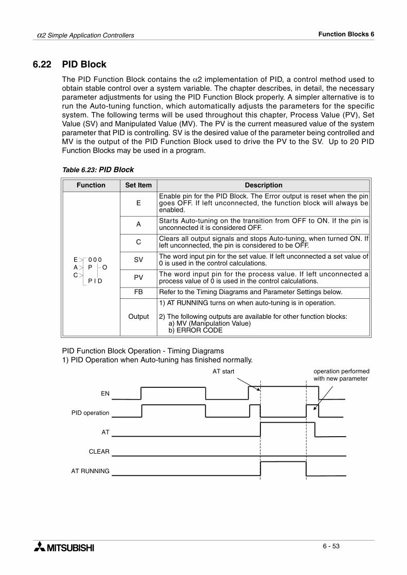
α2 Simple Application Controllers Function Blocks 6
6 - 53
6.22 PID Block
The PID Function Block contains the α2 implementation of PID, a control method used toobtain stable control over a system variable. The chapter describes, in detail, the necessaryparameter adjustments for using the PID Function Block properly. A simpler alternative is torun the Auto-tuning function, which automatically adjusts the parameters for the specificsystem. The following terms will be used throughout this chapter, Process Value (PV), SetValue (SV) and Manipulated Value (MV). The PV is the current measured value of the systemparameter that PID is controlling. SV is the desired value of the parameter being controlled andMV is the output of the PID Function Block used to drive the PV to the SV. Up to 20 PIDFunction Blocks may be used in a program.
Table 6.23: PID Block
PID Function Block Operation - Timing Diagrams1) PID Operation when Auto-tuning has finished normally.
Function Set Item Description
EEnable pin for the PID Block. The Error output is reset when the pingoes OFF. If left unconnected, the function block will always beenabled.
A Starts Auto-tuning on the transition from OFF to ON. If the pin isunconnected it is considered OFF.
C Clears all output signals and stops Auto-tuning, when turned ON. Ifleft unconnected, the pin is considered to be OFF.
SV The word input pin for the set value. If left unconnected a set value of0 is used in the control calculations.
PV The word input pin for the process value. If left unconnected aprocess value of 0 is used in the control calculations.
FB Refer to the Timing Diagrams and Parameter Settings below.
Output
1) AT RUNNING turns on when auto-tuning is in operation.
2) The following outputs are available for other function blocks: a) MV (Manipulation Value) b) ERROR CODE
0 00
IP
OA
D
PE
C
EN
AT
AT RUNNING
CLEAR
AT start operation performedwith new parameter
PID operation
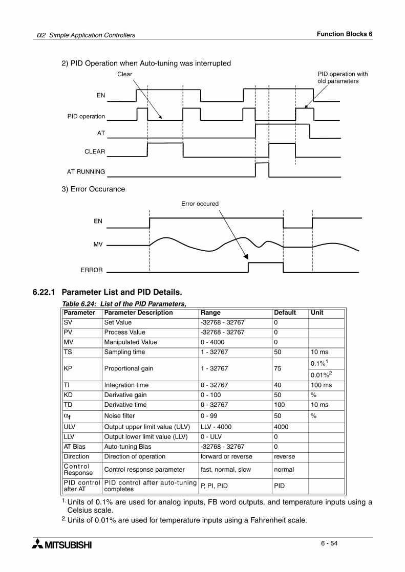
α2 Simple Application Controllers Function Blocks 6
6 - 54
2) PID Operation when Auto-tuning was interrupted
3) Error Occurance
6.22.1 Parameter List and PID Details.
1.Units of 0.1% are used for analog inputs, FB word outputs, and temperature inputs using aCelsius scale.
2.Units of 0.01% are used for temperature inputs using a Fahrenheit scale.
Table 6.24: List of the PID Parameters,Parameter Parameter Description Range Default Unit
SV Set Value -32768 - 32767 0
PV Process Value -32768 - 32767 0
MV Manipulated Value 0 - 4000 0
TS Sampling time 1 - 32767 50 10 ms
KP Proportional gain 1 - 32767 750.1%1
0.01%2
TI Integration time 0 - 32767 40 100 ms
KD Derivative gain 0 - 100 50 %
TD Derivative time 0 - 32767 100 10 ms
αf Noise filter 0 - 99 50 %
ULV Output upper limit value (ULV) LLV - 4000 4000
LLV Output lower limit value (LLV) 0 - ULV 0
AT Bias Auto-tuning Bias -32768 - 32767 0
Direction Direction of operation forward or reverse reverse
Cont ro lResponse Control response parameter fast, normal, slow normal
PID controlafter AT
PID control after auto-tuningcompletes P, PI, PID PID
EN
AT
AT RUNNING
CLEAR
PID operation withold parameters
PID operation
Clear
EN
ERROR
MV
Error occured
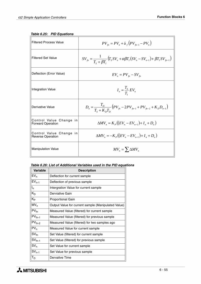
α2 Simple Application Controllers Function Blocks 6
6 - 55
Table 6.25: PID Equations
Filtered Process Value
Filtered Set Value
Deflection (Error Value)
Integration Value
Derivative Value
Cont ro l Va lue Change inForward Operation
Cont ro l Va lue Change inReverse Operation
Manipulation Value
Table 6.26: List of Additional Variables used in the PID equations
Variable Description
EVn Deflection for current sample
EVn-1 Deflection of previous sample
In Intergration Value for current sample
KD Derviative Gain
KP Proportional Gain
MVn Output Value for current sample (Manipulated Value)
PVfn Measured Value (filtered) for current sample
PVfn-1 Measured Value (filtered) for previous sample
PVfn-2 Measured Value (filtered) for two samples ago
PVn Measured Value for current sample
SVfn Set Value (filtered) for current sample
SVfn-1 Set Value (filtered) for previous sample
SVn Set Value for current sample
SVn-1 Set Value for previous sample
TD Dervative Time
( )nfnfnfn PVPVPVPV −+= −1á
( )( )11
1−− +−+
+= fnInnInS
ISfn SVTSVSVTSVT
TTSV βαβ
β
fnfnn SVPVEV −=
nI
Sn EV
T
TI =
( )1212 −−− ++−+
= nDfnfnfnDDS
Dn DKPVPVPV
TKT
TD
( )( )nnnnPn DIEVEVKMV ++−=∆ −1
( )( )nnnnPn DIEVEVKMV ++−−=∆ −1
∑∆= nn MVMV
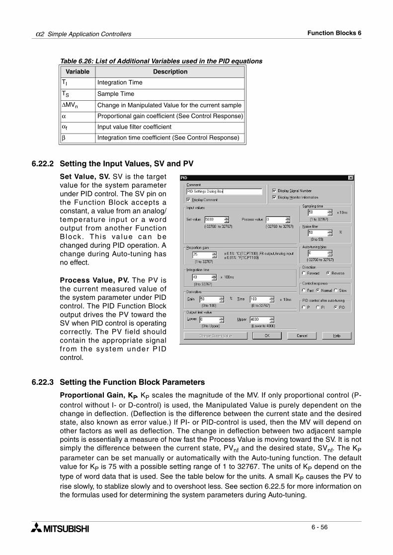
α2 Simple Application Controllers Function Blocks 6
6 - 56
6.22.2 Setting the Input Values, SV and PV
Set Value, SV. SV is the targetvalue for the system parameterunder PID control. The SV pin onthe Function Block accepts aconstant, a value from an analog/temperature input or a wordoutput from another FunctionB lock . Th is va lue can bechanged during PID operation. Achange during Auto-tuning hasno effect.
Process Value, PV. The PV isthe current measured value ofthe system parameter under PIDcontrol. The PID Function Blockoutput drives the PV toward theSV when PID control is operatingcorrectly. The PV field shouldcontain the appropriate signalf rom the system under P IDcontrol.
6.22.3 Setting the Function Block Parameters
Proportional Gain, KP. KP scales the magnitude of the MV. If only proportional control (P-control without I- or D-control) is used, the Manipulated Value is purely dependent on thechange in deflection. (Deflection is the difference between the current state and the desiredstate, also known as error value.) If PI- or PID-control is used, then the MV will depend onother factors as well as deflection. The change in deflection between two adjacent samplepoints is essentially a measure of how fast the Process Value is moving toward the SV. It is notsimply the difference between the current state, PVnf and the desired state, SVnf. The KPparameter can be set manually or automatically with the Auto-tuning function. The defaultvalue for KP is 75 with a possible setting range of 1 to 32767. The units of KP depend on thetype of word data that is used. See the table below for the units. A small KP causes the PV torise slowly, to stablize slowly and to overshoot less. See section 6.22.5 for more information onthe formulas used for determining the system parameters during Auto-tuning.
TI Integration Time
TS Sample Time
∆MVn Change in Manipulated Value for the current sample
α Proportional gain coefficient (See Control Response)
αf Input value filter coefficient
β Integration time coefficient (See Control Response)
Table 6.26: List of Additional Variables used in the PID equations
Variable Description
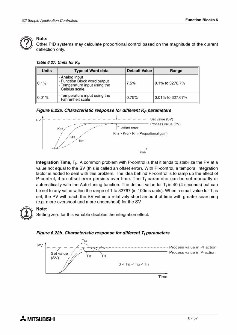
α2 Simple Application Controllers Function Blocks 6
6 - 57
Note:Other PID systems may calculate proportional control based on the magnitude of the currentdeflection only.
Table 6.27: Units for KP
Figure 6.22a. Characteristic response for different KP parameters
Integration Time, TI. A common problem with P-control is that it tends to stabilize the PV at avalue not equal to the SV (this is called an offset error). With PI-control, a temporal integrationfactor is added to deal with this problem. The idea behind PI-control is to ramp up the effect ofP-control, if an offset error persists over time. The TI parameter can be set manually orautomatically with the Auto-tuning function. The default value for TI is 40 (4 seconds) but canbe set to any value within the range of 1 to 32767 (in 100ms units). When a small value for TI isset, the PV will reach the SV within a relatively short amount of time with greater searching(e.g. more overshoot and more undershoot) for the SV.
Note:Setting zero for this variable disables the integration effect.
Figure 6.22b. Characteristic response for different TI parameters
Units Type of Word data Default Value Range
0.1%
· Analog input· Function Block word output· Temperature input using the Celsius scale.
7.5% 0.1% to 3276.7%
0.01% · Temperature input using the Fahrenheit scale 0.75% 0.01% to 327.67%
Time
Set value (SV)Process value (PV)
offset error
KP3 > KP2 > KP1 (Proportional gain)KP3
KP2KP1
PV
Time
Set value(SV)
Process value in P-action
TI3
0 < TI3 < TI2 < TI1
Process value in PI action
TI2 TI1
PV
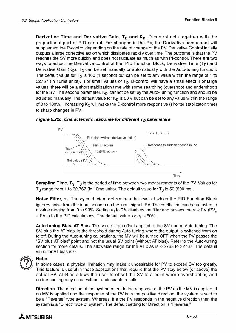
α2 Simple Application Controllers Function Blocks 6
6 - 58
Derivative Time and Derivative Gain, TD and KD. D-control acts together with theproportional part of PID-control. For changes in the PV, the Derivative component willsupplement the P-control depending on the rate of change of the PV. Derivative Control initiallyoutputs a large corrective action which dissipates rapidly over time. The outcome is that the PVreaches the SV more quickly and does not fluctuate as much as with PI-control. There are twoways to adjust the Derivative control of the PID Function Block, Derivative Time (TD) andDerivative Gain (KD). TD can be set manually or automatically with the Auto-tuning function.The default value for TD is 100 (1 second) but can be set to any value within the range of 1 to32767 (in 10ms units). For small values of TD, D-control will have a small effect. For largevalues, there will be a short stablization time with some searching (overshoot and undershoot)for the SV. The second parameter, KD, cannot be set by the Auto-Tuning function and should beadjusted manually. The default value for KD is 50% but can be set to any value within the rangeof 0 to 100%. Increasing KD will make the D-control more responsive (shorter stablizaton time)to sharp changes in PV.
Figure 6.22c. Characteristic response for different TD parameters
Sampling Time, TS. TS is the period of time between two measurements of the PV. Values forTS range from 1 to 32,767 (in 10ms units). The default value for TS is 50 (500 ms).
Noise Filter, αf. The αf coefficient determines the level at which the PID Function Blockignores noise from the input sensors on the input signal, PV. The coefficient can be adjusted toa value ranging from 0 to 99%. Setting αf to 0% disables the filter and passes the raw PV (PVn= PVnf) to the PID calculations. The default value for αf is 50%.
Auto-tuning Bias, AT Bias. This value is an offset applied to the SV during Auto-tuning. TheSV, plus the AT bias, is the threshold during Auto-tuning where the output is switched from onto off. During the Auto-tuning calibrations, the MV will be turned OFF when the PV passes the“SV plus AT bias” point and not the usual SV point (without AT bias). Refer to the Auto-tuningsection for more details. The allowable range for the AT bias is -32768 to 32767. The defaultvalue for AT bias is 0.
Note: In some cases, a physical limitation may make it undesirable for PV to exceed SV too greatly.This feature is useful in those applications that require that the PV stay below (or above) theactual SV. AT-Bias allows the user to offset the SV to a point where overshooting andundershooting may occur without undesirable results.
Direction. The direction of the system refers to the response of the PV as the MV is applied. Ifan MV is applied and the response of the PV is in the positive direction, the system is said tobe a “Reverse” type system. Whereas, if a the PV responds in the negative direction then thesystem is a “Direct” type of system. The default setting for Direction is “Reverse.”
Time
Set value (SV)
PI action (without derivative action)
Response to sudden change in PVTD1(PID action)
TD2(PID action)TD3
(PID action)
TD3 > TD2 > TD1
PV
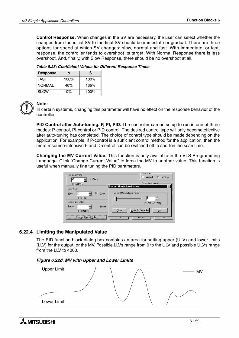
α2 Simple Application Controllers Function Blocks 6
6 - 59
Control Response. When changes in the SV are necessary, the user can select whether thechanges from the initial SV to the final SV should be immediate or gradual. There are threeoptions for speed at which SV changes: slow, normal and fast. With immediate, or fast,response, the controller tends to overshoot its target. With Normal Response there is lessovershoot. And, finally, with Slow Response, there should be no overshoot at all.
Table 6.28: Coefficient Values for Different Response Times
Note: In certain systems, changing this parameter will have no effect on the response behavior of thecontroller.
PID Control after Auto-tuning. P, PI, PID. The controller can be setup to run in one of threemodes: P-control, PI-control or PID-control. The desired control type will only become effectiveafter auto-tuning has completed. The choice of control type should be made depending on theapplication. For example, if P-control is a sufficient control method for the application, then themore resource-intensive I- and D-control can be switched off to shorten the scan time.
Changing the MV Current Value. This function is only available in the VLS ProgrammingLanguage. Click “Change Current Value” to force the MV to another value. This function isuseful when manually fine tuning the PID parameters.
6.22.4 Limiting the Manipulated Value
The PID function block dialog box contains an area for setting upper (ULV) and lower limits(LLV) for the output, or the MV. Possible LLVs range from 0 to the ULV and possible ULVs rangefrom the LLV to 4000.
Figure 6.22d. MV with Upper and Lower Limits
Response αααα ββββ
FAST 100% 100%
NORMAL 40% 135%
SLOW 0% 100%
Upper LimitMV
Lower Limit
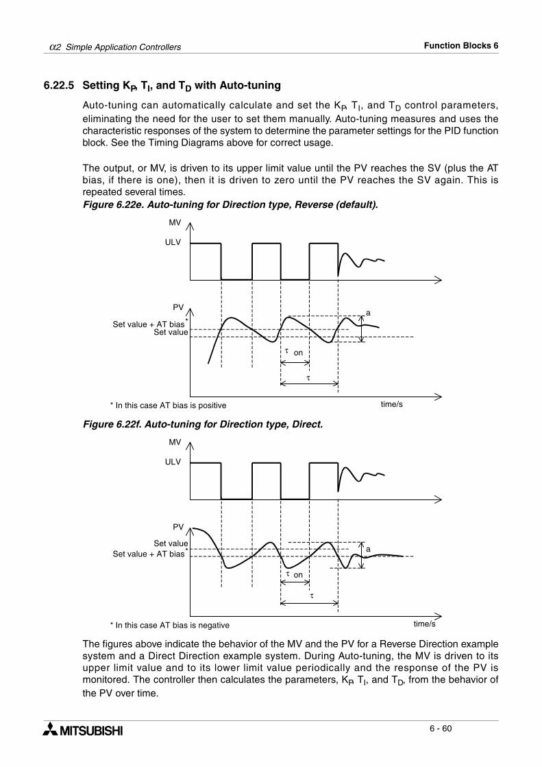
α2 Simple Application Controllers Function Blocks 6
6 - 60
6.22.5 Setting KP, TI, and TD with Auto-tuning
Auto-tuning can automatically calculate and set the KP, TI, and TD control parameters,eliminating the need for the user to set them manually. Auto-tuning measures and uses thecharacteristic responses of the system to determine the parameter settings for the PID functionblock. See the Timing Diagrams above for correct usage.
The output, or MV, is driven to its upper limit value until the PV reaches the SV (plus the ATbias, if there is one), then it is driven to zero until the PV reaches the SV again. This isrepeated several times. Figure 6.22e. Auto-tuning for Direction type, Reverse (default).
Figure 6.22f. Auto-tuning for Direction type, Direct.
The figures above indicate the behavior of the MV and the PV for a Reverse Direction examplesystem and a Direct Direction example system. During Auto-tuning, the MV is driven to itsupper limit value and to its lower limit value periodically and the response of the PV ismonitored. The controller then calculates the parameters, KP, TI, and TD, from the behavior ofthe PV over time.
PV
time/s
MV
a
ULV
τ on
Set valueSet value + AT bias*
* In this case AT bias is positive
τ
PV
time/s
MV
a
ULV
on
Set valueSet value + AT bias*
* In this case AT bias is negative
τ
τ
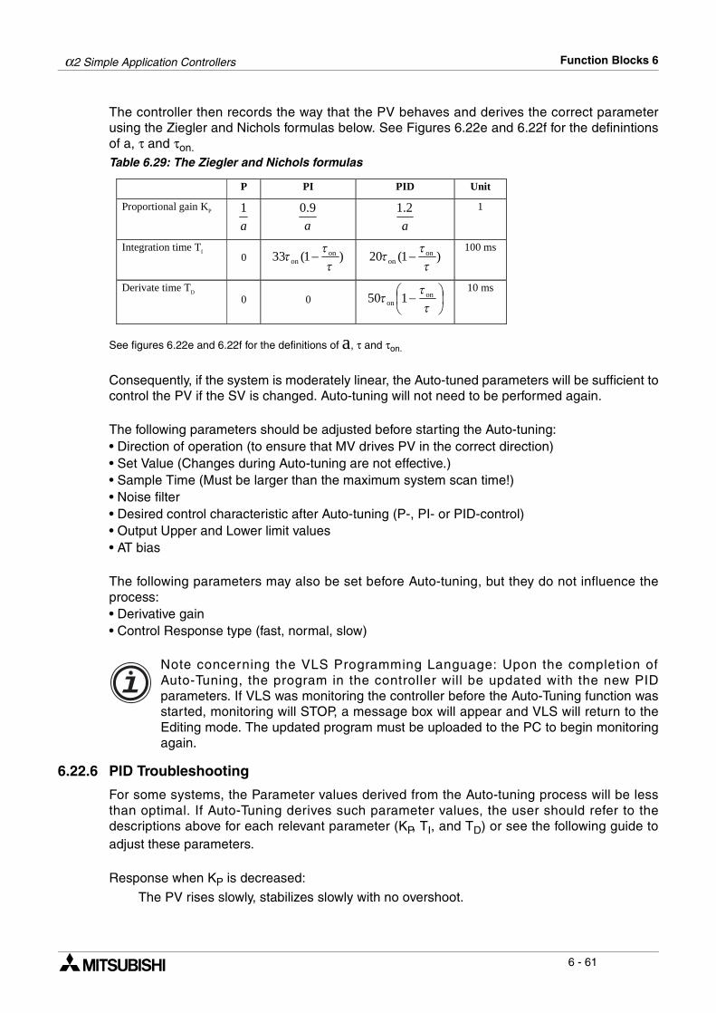
α2 Simple Application Controllers Function Blocks 6
6 - 61
The controller then records the way that the PV behaves and derives the correct parameterusing the Ziegler and Nichols formulas below. See Figures 6.22e and 6.22f for the definintionsof a, τ and τon.Table 6.29: The Ziegler and Nichols formulas
See figures 6.22e and 6.22f for the definitions of a, τ and τon.
Consequently, if the system is moderately linear, the Auto-tuned parameters will be sufficient tocontrol the PV if the SV is changed. Auto-tuning will not need to be performed again.
The following parameters should be adjusted before starting the Auto-tuning:• Direction of operation (to ensure that MV drives PV in the correct direction)• Set Value (Changes during Auto-tuning are not effective.)• Sample Time (Must be larger than the maximum system scan time!)• Noise filter• Desired control characteristic after Auto-tuning (P-, PI- or PID-control)• Output Upper and Lower limit values• AT bias
The following parameters may also be set before Auto-tuning, but they do not influence theprocess:• Derivative gain • Control Response type (fast, normal, slow)
Note concerning the VLS Programming Language: Upon the completion ofAuto-Tuning, the program in the controller will be updated with the new PIDparameters. If VLS was monitoring the controller before the Auto-Tuning function wasstarted, monitoring will STOP, a message box will appear and VLS will return to theEditing mode. The updated program must be uploaded to the PC to begin monitoringagain.
6.22.6 PID Troubleshooting
For some systems, the Parameter values derived from the Auto-tuning process will be lessthan optimal. If Auto-Tuning derives such parameter values, the user should refer to thedescriptions above for each relevant parameter (KP, TI, and TD) or see the following guide toadjust these parameters.
Response when KP is decreased:
The PV rises slowly, stabilizes slowly with no overshoot.
P PI PID Unit
Proportional gain KP
a
1
a
0.9
a
1.2
1
Integration time TI 0 )1(33 on
on !!
! " )1(20 onon !
!! "
100 ms
Derivate time TD 0 0 #
$%
&'( "
!!
! onon 150
10 ms
α2 Simple Application Controllers Function Blocks 6
6 - 62
Response when TI is increased:
The PV stabilizes slowly with less searching (overshoot and undershoot) for the SV.
Response when TD is increased:
The PV stabilizes quickly. There is more searching (overshoot and undershoot) for the SV.
6.22.7 Error Codes
Error Codes are reported by the PID Function Block via the string output pin. The error codebyte consists of 8 error flags, but only the lower 6 bits are functional. An error code value ofzero means there is no error.
1. This is the maximum change in PV when the input filter is 0%. In the case of a higher inputfilter, the maximum change in PV can be higher.2. Bit 5 of the error code is set when the calculated PID parameters are out of range. Bit 5 is not
set when AT is stopped by the user.
Setup of the PID Function Block directly from the α2 Series Controller
1 ) Allocate the input pin to be used for the function block.
2 ) Press the “OK” key with the cursor in the function block. The function block edit screen isdisplayed as shown.
3 ) Press the “OK” button to setup the parameters for the PID function block.
4 ) Highlight SetValue and select it using the “OK” button. Choose from DirectSet, Analog In,or FB Value for the Set Value of the PID function block.
Table 6.30: Bit Content State of processing
b0 Sampling time < (system) scan time
PID operation continued
b1Filtered PV change overflow (∆PVfn < -21692 or ∆PVfn > 21692)1
b2 Deflection overflow (EV < -32768 or EV > 32767)
b3 Integration result overflow (out of range: [-32768, 32767])
b4 Derivative overflow (out of range: [-32768, 32767])
b52 Internal error during auto-tuning operation AT ends
S e t u p BC h a n g e
B 0 0 1 : P IFD
N oD e l e t e F B
S e t aV uP r o c e s
B 0 0 1 : P IlD
aVS amp l e T i
es l
me
D i r tc eA n a l o g
B 0 0 1 : P ISD
nIF B V a l e
t
u
e

α2 Simple Application Controllers Function Blocks 6
6 - 63
5 ) After selecting the appropriate constant, analog input or word output, press the “OK”button to return to the function block settings menu.
6 ) Highlight and select Process Val using the “OK” button. Choose from DirectSet, Analog Inor FB Value for the Process Value of the PID function block.
7 ) After selecting the appropriate constant, analog input or word output, press the “OK”button to return to the function block settings menu.
8 ) Highlight Sample Time using the up and down keys.
9 ) Press the “OK” button and enter a value using the “+” and “-” buttons.
10 )Press the “OK” button to return to the function block settings menu. Highlight KP using the“ and ” button.
11 )Press the “OK” button and enter a KP value using the “+” and “-” buttons.
12 )Press the “OK” button to return to the function block settings menu. Highlight Ti using the“ and ” button.
S e t aV uP r o c e s
B 0 0 1 : P IlD
aVS amp l e T i
es l
me
D i r tc eA n a l o g
B 0 0 1 : P ISD
nIF B V a l e
t
u
e
S e t aV uP r o c e s
B 0 0 1 : P Il
D
aVS a m p l e T i
es l
m e
S e t aV uP r o c e s
B 0 0 1 : P IlD
aVS amp l e T i
es l
me
0 .
B 0 0 1 : P I D
s0S amp l e T i
5me
B 0 0 1 : P I D
K p
P r o c e s aVS amp l e T i
s lme
B 0 0 1 : P I DK p
7 . 5 %
B 0 0 1 : P I D
T iK pS amp l e T i me
α2 Simple Application Controllers Function Blocks 6
6 - 64
13 )Press the “OK” button and enter a Ti value using the “+” and “-” buttons.
14 )Press the “OK” button to return to the function block settings menu. Highlight Td using the“ and ” button.
15 )Press the “OK” button and enter a Td value using the “+” and “-” buttons.
16 )Press the “OK” button to return to the function block settings menu. Highlight Kd using the“ and ” button.
17 )Press the “OK” button and enter a Kd value using the “+” and “-” buttons.
18 )Press the “OK” button to return to the function block settings menu. Highlight NoiseFilterusing the “ and ” button.
19 )Press the “OK” button and enter a NoiseFilter value using the “+” and “-” buttons.
20 )Press the “OK” button to return to the function block settings menu. Highlight Upper Limitusing the “ and ” button.
B 0 0 1 : P I DT i
4 . 0 s
B 0 0 1 : P I D
T dT iK p
B 0 0 1 : P I DT d
1 . 0 0 s
B 0 0 1 : P I D
K dT dT i
B 0 0 1 : P I DK d
5 0 %
B 0 0 1 : P I D
N oK dT d
i s e F i l t e r
B 0 0 1 : P I D
5 0 %N o i s e F i l t e r
B 0 0 1 : P I D
U p
K d
p e r L i m i tN o i s e F i l t e r
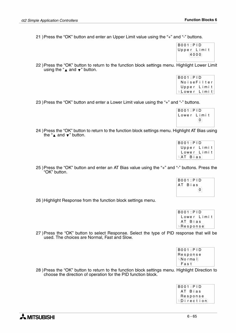
α2 Simple Application Controllers Function Blocks 6
6 - 65
21 )Press the “OK” button and enter an Upper Limit value using the “+” and “-” buttons.
22 )Press the “OK” button to return to the function block settings menu. Highlight Lower Limitusing the “ and ” button.
23 )Press the “OK” button and enter a Lower Limit value using the “+” and “-” buttons.
24 )Press the “OK” button to return to the function block settings menu. Highlight AT Bias usingthe “ and ” button.
25 )Press the “OK” button and enter an AT Bias value using the “+” and “-” buttons. Press the“OK” button.
26 )Highlight Response from the function block settings menu.
27 )Press the “OK” button to select Response. Select the type of PID response that will beused. The choices are Normal, Fast and Slow.
28 )Press the “OK” button to return to the function block settings menu. Highlight Direction tochoose the direction of operation for the PID function block.
B 0 0 1 : P I D
0 0U p p e r L i m i t
4 0
B 0 0 1 : P I D
L o w e r L i m i tU p p e r L i m i tN o i s e F i l t e r
B 0 0 1 : P I D
0L o w e r L i m i t
B 0 0 1 : P I D
A T B i sL o w e r L i m i tU p p e r L i m i t
a
B 0 0 1 : P I D
0A T B i a s
L o w re iA T B i a
B 0 0 1 : P ILD
R e s p o n s e
ms
i t
N o ma l
B 0 0 1 : P I D
F a s t
R e s p o n s er
B 0 0 1 : P I D
D i r e c t i o
A T B i aR e s p o n s e
s
n
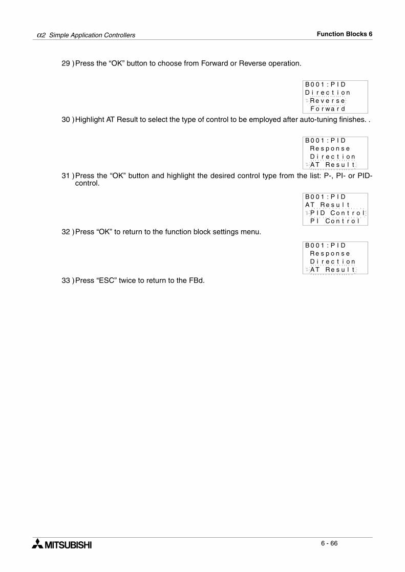
α2 Simple Application Controllers Function Blocks 6
6 - 66
29 )Press the “OK” button to choose from Forward or Reverse operation.
30 )Highlight AT Result to select the type of control to be employed after auto-tuning finishes. .
31 )Press the “OK” button and highlight the desired control type from the list: P-, PI- or PID-control.
32 )Press “OK” to return to the function block settings menu.
33 )Press “ESC” twice to return to the FBd.
B 0 0 1 : P I D
F o r w a r dR e v e r s e
D i r e c t i o n
B 0 0 1 : P I D
A T R e s u l tD i r e c t i oR e s p o n s e
n
B 0 0 1 : P I D
P I D C o n t rA T R e s u l t
o lP I C o n t r o l
B 0 0 1 : P I D
A T R e s u l tD i r e c t i oR e s p o n s e
n
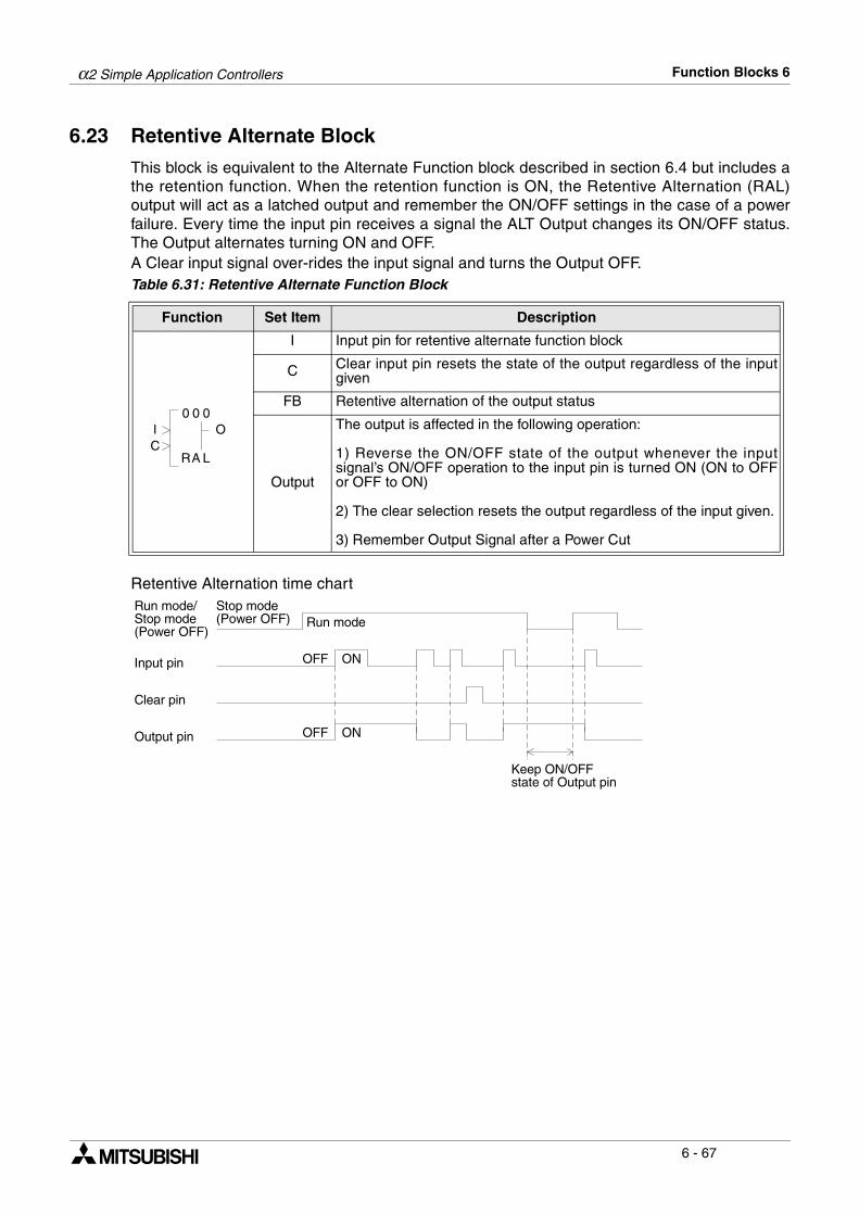
α2 Simple Application Controllers Function Blocks 6
6 - 67
6.23 Retentive Alternate Block
This block is equivalent to the Alternate Function block described in section 6.4 but includes athe retention function. When the retention function is ON, the Retentive Alternation (RAL)output will act as a latched output and remember the ON/OFF settings in the case of a powerfailure. Every time the input pin receives a signal the ALT Output changes its ON/OFF status.The Output alternates turning ON and OFF.A Clear input signal over-rides the input signal and turns the Output OFF.Table 6.31: Retentive Alternate Function Block
Retentive Alternation time chart
Function Set Item Description
I Input pin for retentive alternate function block
C Clear input pin resets the state of the output regardless of the inputgiven
FB Retentive alternation of the output status
Output
The output is affected in the following operation:
1) Reverse the ON/OFF state of the output whenever the inputsignal’s ON/OFF operation to the input pin is turned ON (ON to OFFor OFF to ON)
2) The clear selection resets the output regardless of the input given.
3) Remember Output Signal after a Power Cut
0 00
LA
OIC
R
Input pin OFF ON
Clear pin
Stop mode(Power OFF) Run mode
OFF ON
Keep ON/OFFstate of Output pin
Run mode/Stop mode(Power OFF)
Output pin

α2 Simple Application Controllers Function Blocks 6
6 - 68
6.24 Addition Block
The function block is used to summate inputs A and B hence produce the resultant Y.Table 6.32: Addition Function Block
Setup of the Addition Function Block directly from the α2 Series Controller1 ) Allocate the input pin to be used for the function block. 2 ) Press the “OK” key with the cursor in the function block. The function block edit screen is
displayed as shown.
3 ) Press the “OK” Key and enter the function block settings using the “ and ” keys. TheAddition operation Y=A+B must be specified.
4 ) Using the “ and ” keys highlight Constant A and press the “OK” key to enter either aDirectset, Analog In or FB Value.
5 ) Repeat step 4 for Constant B and return to the FBd using the “ESC” key.
Function Set Item Description
I Input pin for addition function block
FB
This function block operates the expression Y=A+B.
The value of Y,A and B is in the range: -32768 to 32767 a) A,B - Constant value (Setting range:-32768 to 32767 - Analog value - FB value
Output
1) Word OutputWhen the input pin is ON, Y=A+B is executed and the word outputwill be given the result. When the input pin is OFF the expression isnot executed and the Y value will retain the last result.
2) Bit Output- Operation result Y<-32768: Output pin turned ON and the operationresult Y will be set to -32768
- Operation result Y>32767: Output pin turned ON and the operationresult Y will be set to 32767
0 00
DA
OI
D
P
B 0 0 1 : A
C h a n g e N oD e l e t e F B
DDS e t u p F B
B 0 0 1 : A DDO u t p u t aV ly = A + B
0
D i r e c t S e tA n a l o g I nF B V a l u e
B 0 0 1 : A DD
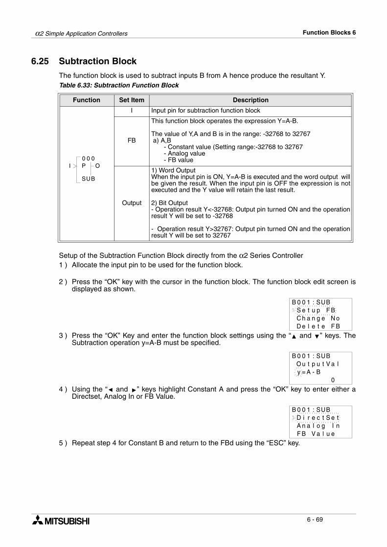
α2 Simple Application Controllers Function Blocks 6
6 - 69
6.25 Subtraction Block
The function block is used to subtract inputs B from A hence produce the resultant Y.Table 6.33: Subtraction Function Block
Setup of the Subtraction Function Block directly from the α2 Series Controller1 ) Allocate the input pin to be used for the function block.
2 ) Press the “OK” key with the cursor in the function block. The function block edit screen isdisplayed as shown.
3 ) Press the “OK” Key and enter the function block settings using the “ and ” keys. TheSubtraction operation y=A-B must be specified.
4 ) Using the “ and ” keys highlight Constant A and press the “OK” key to enter either aDirectset, Analog In or FB Value.
5 ) Repeat step 4 for Constant B and return to the FBd using the “ESC” key.
Function Set Item Description
I Input pin for subtraction function block
FB
This function block operates the expression Y=A-B.
The value of Y,A and B is in the range: -32768 to 32767 a) A,B - Constant value (Setting range:-32768 to 32767 - Analog value - FB value
Output
1) Word OutputWhen the input pin is ON, Y=A-B is executed and the word output willbe given the result. When the input pin is OFF the expression is notexecuted and the Y value will retain the last result.
2) Bit Output- Operation result Y<-32768: Output pin turned ON and the operationresult Y will be set to -32768
- Operation result Y>32767: Output pin turned ON and the operationresult Y will be set to 32767
0 00
US
OI
B
P
B 0 0 1 : S
C h a n g e N oD e l e t e F B
BUS e t u p F B
O u t p u t aV ly = A - B
0
B 0 0 1 : S BU
D i r e c t S e tA n a l o g I nF B V a l u e
B 0 0 1 : S BU
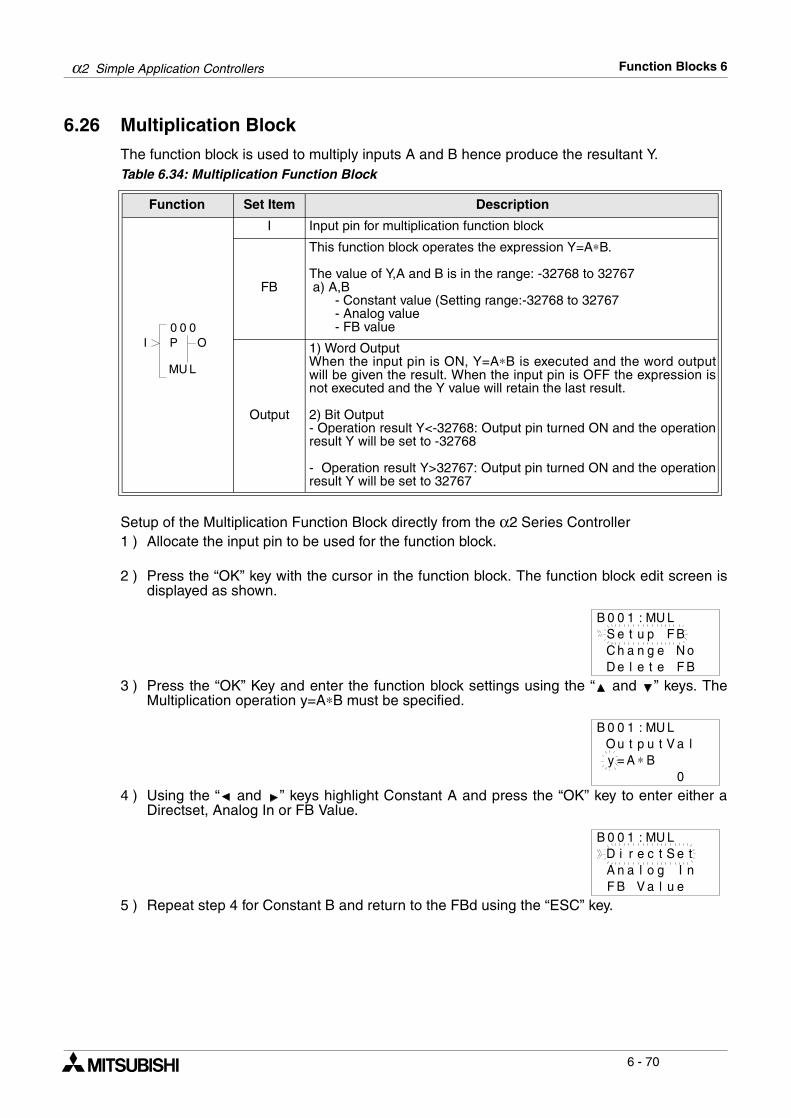
α2 Simple Application Controllers Function Blocks 6
6 - 70
6.26 Multiplication Block
The function block is used to multiply inputs A and B hence produce the resultant Y.Table 6.34: Multiplication Function Block
Setup of the Multiplication Function Block directly from the α2 Series Controller1 ) Allocate the input pin to be used for the function block.
2 ) Press the “OK” key with the cursor in the function block. The function block edit screen isdisplayed as shown.
3 ) Press the “OK” Key and enter the function block settings using the “ and ” keys. TheMultiplication operation y=A∗B must be specified.
4 ) Using the “ and ” keys highlight Constant A and press the “OK” key to enter either aDirectset, Analog In or FB Value.
5 ) Repeat step 4 for Constant B and return to the FBd using the “ESC” key.
Function Set Item Description
I Input pin for multiplication function block
FB
This function block operates the expression Y=A∗B.
The value of Y,A and B is in the range: -32768 to 32767 a) A,B - Constant value (Setting range:-32768 to 32767 - Analog value - FB value
Output
1) Word OutputWhen the input pin is ON, Y=A∗B is executed and the word outputwill be given the result. When the input pin is OFF the expression isnot executed and the Y value will retain the last result.
2) Bit Output- Operation result Y<-32768: Output pin turned ON and the operationresult Y will be set to -32768
- Operation result Y>32767: Output pin turned ON and the operationresult Y will be set to 32767
0 00
UM
OI
L
P
B 0 0 1 : M
C h a n g e N oD e l e t e F B
LUS e t u p F B
O u t p u t aV ly = A ∗ B
0
B 0 0 1 : M LU
D i r e c t S e tA n a l o g I nF B V a l u e
B 0 0 1 : M LU
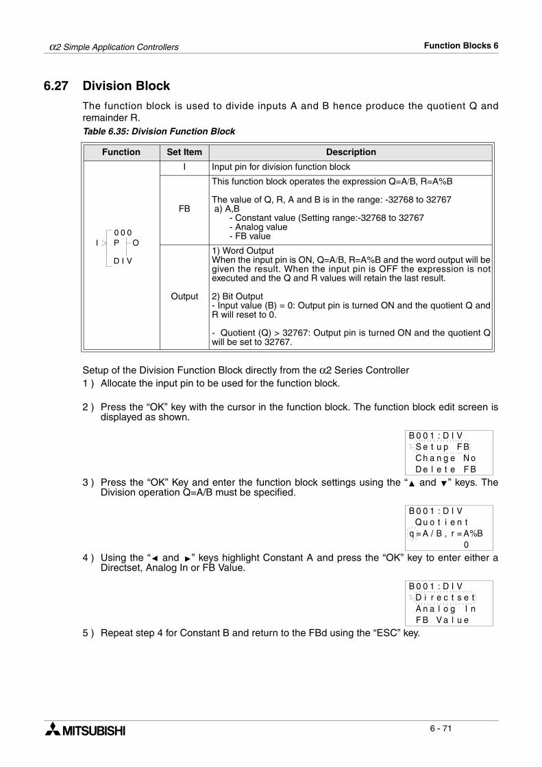
α2 Simple Application Controllers Function Blocks 6
6 - 71
6.27 Division Block
The function block is used to divide inputs A and B hence produce the quotient Q andremainder R.Table 6.35: Division Function Block
Setup of the Division Function Block directly from the α2 Series Controller1 ) Allocate the input pin to be used for the function block.
2 ) Press the “OK” key with the cursor in the function block. The function block edit screen isdisplayed as shown.
3 ) Press the “OK” Key and enter the function block settings using the “ and ” keys. TheDivision operation Q=A/B must be specified.
4 ) Using the “ and ” keys highlight Constant A and press the “OK” key to enter either aDirectset, Analog In or FB Value.
5 ) Repeat step 4 for Constant B and return to the FBd using the “ESC” key.
Function Set Item Description
I Input pin for division function block
FB
This function block operates the expression Q=A/B, R=A%B
The value of Q, R, A and B is in the range: -32768 to 32767 a) A,B - Constant value (Setting range:-32768 to 32767 - Analog value - FB value
Output
1) Word OutputWhen the input pin is ON, Q=A/B, R=A%B and the word output will begiven the result. When the input pin is OFF the expression is notexecuted and the Q and R values will retain the last result.
2) Bit Output- Input value (B) = 0: Output pin is turned ON and the quotient Q andR will reset to 0.
- Quotient (Q) > 32767: Output pin is turned ON and the quotient Qwill be set to 32767.
0 00
ID
OI
V
P
B 0 0 1 : D
C h a n g e N oD e l e t e F B
VIS e t u p F B
Q u o t i e tnq = A / B
0
B 0 0 1 : D VI
, r = A%B
D i r e c t s e tA n a l o g I nF B V a l u e
B 0 0 1 : D VI
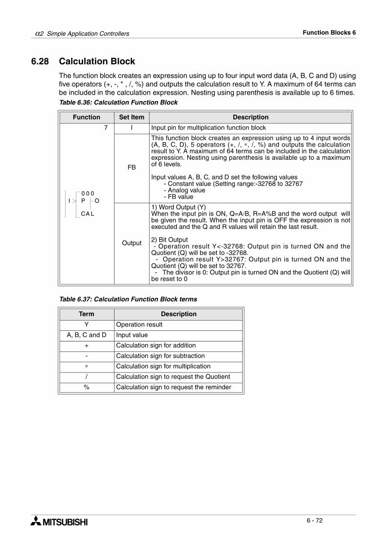
α2 Simple Application Controllers Function Blocks 6
6 - 72
6.28 Calculation Block
The function block creates an expression using up to four input word data (A, B, C and D) usingfive operators (+, -, * , /, %) and outputs the calculation result to Y. A maximum of 64 terms canbe included in the calculation expression. Nesting using parenthesis is available up to 6 times.Table 6.36: Calculation Function Block
Table 6.37: Calculation Function Block terms
Function Set Item Description
7 I Input pin for multiplication function block
FB
This function block creates an expression using up to 4 input words(A, B, C, D), 5 operators (+, /, ∗, /, %) and outputs the calculationresult to Y. A maximum of 64 terms can be included in the calculationexpression. Nesting using parenthesis is available up to a maximumof 6 levels.
Input values A, B, C, and D set the following values - Constant value (Setting range:-32768 to 32767 - Analog value - FB value
Output
1) Word Output (Y)When the input pin is ON, Q=A/B, R=A%B and the word output willbe given the result. When the input pin is OFF the expression is notexecuted and the Q and R values will retain the last result.
2) Bit Output - Operation result Y<-32768: Output pin is turned ON and theQuotient (Q) will be set to -32768. - Operation result Y>32767: Output pin is turned ON and theQuotient (Q) will be set to 32767. - The divisor is 0: Output pin is turned ON and the Quotient (Q) willbe reset to 0
Term Description
Y Operation result
A, B, C and D Input value
+ Calculation sign for addition
- Calculation sign for subtraction
∗ Calculation sign for multiplication
/ Calculation sign to request the Quotient
% Calculation sign to request the reminder
0 00
AC
OI
L
P
α2 Simple Application Controllers Function Blocks 6
6 - 73
Setup of the Calculation Function Block directly from the α2 Series Controller1 ) Allocate the input pin to be used for the function block.
2 ) Press the “OK” key with the cursor in the function block. The function block edit screen is displayed as shown.
3 ) Press the “OK” Key and enter the function block settings using the “ and ” keys. TheCalculate operation [y= ] must be specified.
4 ) While the cursor is flashing, use the “ and ” keys to select the appropriate character orconstant for your intended calculation. The following items are offered: A, B, C, D, +, -, *, /,%, ( or )
5 ) DirectSet values, Analog In or FB Value can all be entered for each constant.
6 ) Return to the FBd using the “ESC” key.
C h a n g e N oD e l e t e F B
B 0 0 1 : C LAS e t u p F B
[ y = ]B 0 0 1 : C LA 3
C o n t a n t A0
[ y = ]B 0 0 1 : C LA 3
As
D i r e c t S e tA n a l o g I nF B V a l u e
B 0 0 1 : C LA
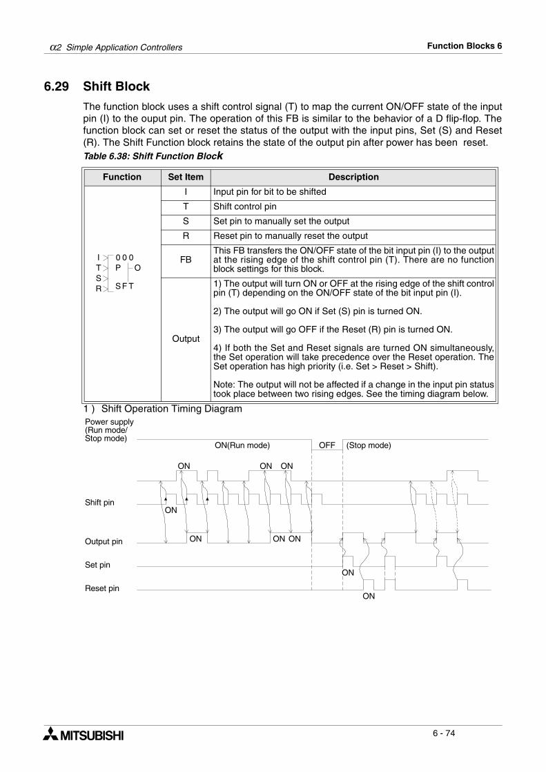
α2 Simple Application Controllers Function Blocks 6
6 - 74
6.29 Shift Block
The function block uses a shift control signal (T) to map the current ON/OFF state of the inputpin (I) to the ouput pin. The operation of this FB is similar to the behavior of a D flip-flop. Thefunction block can set or reset the status of the output with the input pins, Set (S) and Reset(R). The Shift Function block retains the state of the output pin after power has been reset.Table 6.38: Shift Function Block
1 ) Shift Operation Timing Diagram
Function Set Item Description
I Input pin for bit to be shifted
T Shift control pin
S Set pin to manually set the output
R Reset pin to manually reset the output
FBThis FB transfers the ON/OFF state of the bit input pin (I) to the outputat the rising edge of the shift control pin (T). There are no functionblock settings for this block.
Output
1) The output will turn ON or OFF at the rising edge of the shift controlpin (T) depending on the ON/OFF state of the bit input pin (I).
2) The output will go ON if Set (S) pin is turned ON.
3) The output will go OFF if the Reset (R) pin is turned ON.
4) If both the Set and Reset signals are turned ON simultaneously,the Set operation will take precedence over the Reset operation. TheSet operation has high priority (i.e. Set > Reset > Shift).
Note: The output will not be affected if a change in the input pin statustook place between two rising edges. See the timing diagram below.
0 00I
TS
OTSR F
P
Shift pin
Output pin
ON
ON ON ON
ON
ON
ON ONON
Power supply(Run mode/Stop mode)
Set pin
Reset pin
ON(Run mode) OFF (Stop mode)
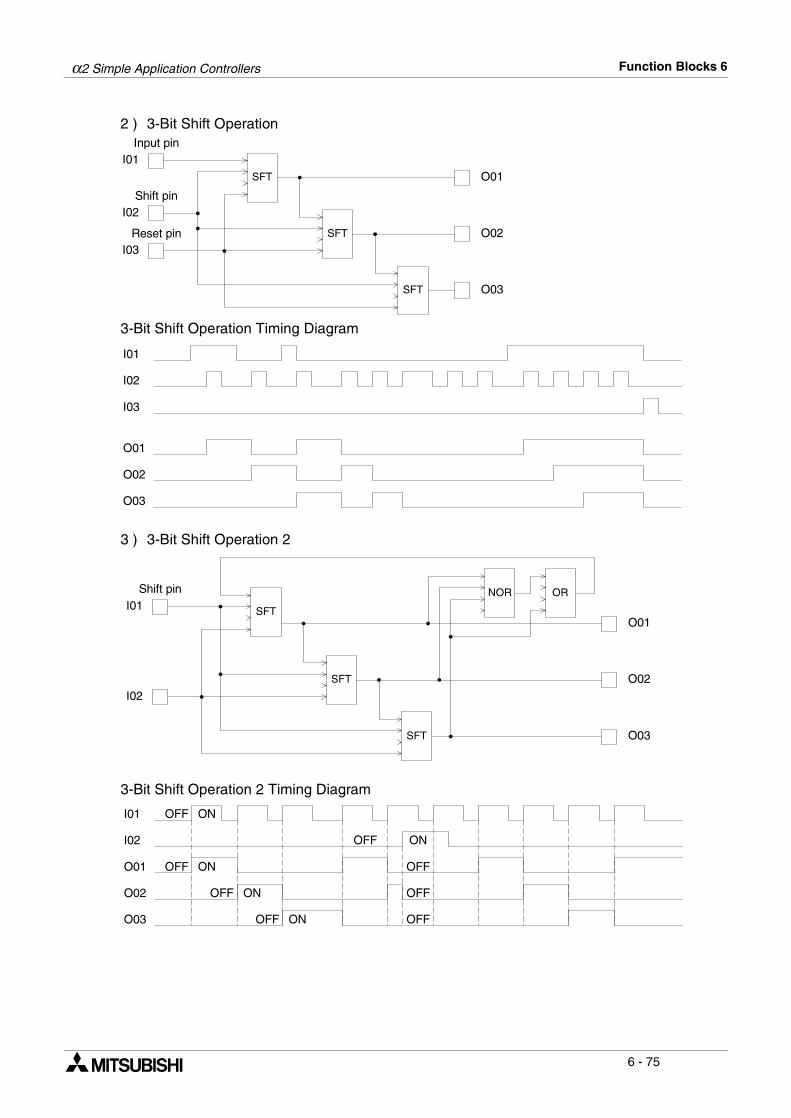
α2 Simple Application Controllers Function Blocks 6
6 - 75
2 ) 3-Bit Shift Operation
3-Bit Shift Operation Timing Diagram
3 ) 3-Bit Shift Operation 2
3-Bit Shift Operation 2 Timing Diagram
I01
I02
I03
Input pin
Shift pin
Reset pin
SFT
SFT
SFT
O01
O02
O03
I01
I02
I03
O01
O02
O03
I01
I02
SFT
SFT
SFT
O01
O02
O03
NOR ORShift pin
I01
I02
O01
O02
O03
OFF ON
OFF ON
OFF
OFF ON
ON
OFF
OFF
OFF
ONOFF
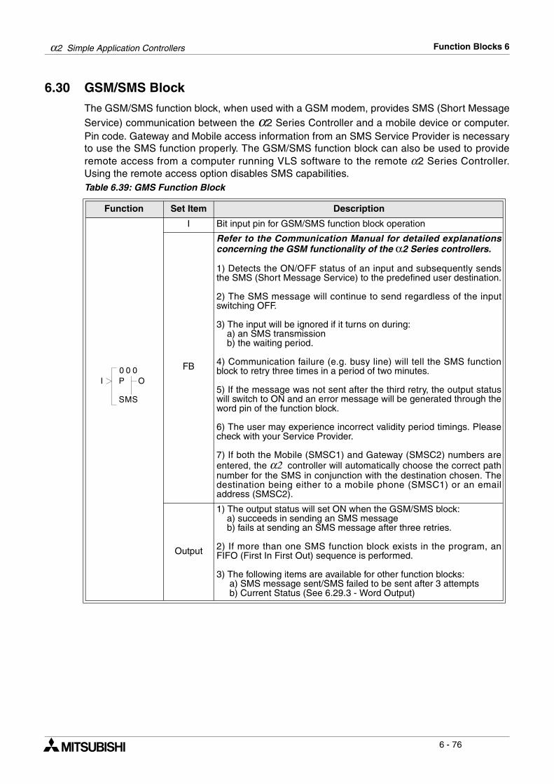
α2 Simple Application Controllers Function Blocks 6
6 - 76
6.30 GSM/SMS Block
The GSM/SMS function block, when used with a GSM modem, provides SMS (Short MessageService) communication between the α2 Series Controller and a mobile device or computer.Pin code. Gateway and Mobile access information from an SMS Service Provider is necessaryto use the SMS function properly. The GSM/SMS function block can also be used to provideremote access from a computer running VLS software to the remote α2 Series Controller.Using the remote access option disables SMS capabilities.Table 6.39: GMS Function Block
Function Set Item Description
I Bit input pin for GSM/SMS function block operation
FB
Refer to the Communication Manual for detailed explanationsconcerning the GSM functionality of the α2 Series controllers.
1) Detects the ON/OFF status of an input and subsequently sendsthe SMS (Short Message Service) to the predefined user destination.
2) The SMS message will continue to send regardless of the inputswitching OFF.
3) The input will be ignored if it turns on during: a) an SMS transmission b) the waiting period.
4) Communication failure (e.g. busy line) will tell the SMS functionblock to retry three times in a period of two minutes.
5) If the message was not sent after the third retry, the output statuswill switch to ON and an error message will be generated through theword pin of the function block.
6) The user may experience incorrect validity period timings. Pleasecheck with your Service Provider.
7) If both the Mobile (SMSC1) and Gateway (SMSC2) numbers areentered, the α2 controller will automatically choose the correct pathnumber for the SMS in conjunction with the destination chosen. Thedestination being either to a mobile phone (SMSC1) or an emailaddress (SMSC2).
Output
1) The output status will set ON when the GSM/SMS block: a) succeeds in sending an SMS message b) fails at sending an SMS message after three retries.
2) If more than one SMS function block exists in the program, anFIFO (First In First Out) sequence is performed.
3) The following items are available for other function blocks: a) SMS message sent/SMS failed to be sent after 3 attempts b) Current Status (See 6.29.3 - Word Output)
0 00
MS
OI
S
P
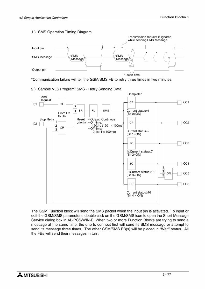
α2 Simple Application Controllers Function Blocks 6
6 - 77
1 ) SMS Operation Timing Diagram
*Communication failure will tell the GSM/SMS FB to retry three times in two minutes.
2 ) Sample VLS Program: SMS - Retry Sending Data
The GSM Function block will send the SMS packet when the input pin is activated. To input oredit the GSM/SMS parameters, double click on the GSM/SMS icon to open the Short MessageService dialog box in AL-PCS/WIN-E. When two or more Function Blocks are trying to send amessage at the same time, the one to connect first will send its SMS message or attempt tosend its message three times. The other GSM/SMS FB(s) will be placed in “Wait” status. Allthe FBs will send their messages in turn.
SMS Message
Output pin
*SMSMessage
Input pin
SMSMessage
* *
1 scan time
Transmission request is ignoredwhile sending SMS Message.
I01
I02
SendRequest
Stop Retry
PL
SR FL
O01
O02
O03
OR
Resetpriority
From Offto On
123
• Output: Continous• On time: 120.1s (1201 × 100ms)• Off time: 0.1s (1 × 100ms)
SMS
CP
Completed
Current status=1(Bit 0=ON)
4≤Current status≤7(Bit 2=ON)
8≤Current status≤15(Bit 3=ON)
Current status≥16(Bit 4 = ON)
ZC
ZC
CP
CP
Current status=2(Bit 1=ON)
O04
O06
O05OR
123
S
R
α2 Simple Application Controllers Function Blocks 6
6 - 78
6.30.1 Input Signal
The α2 controller will send the SMS message to the chosen destination when the input pin isactivated. The operation will continue until the message is sent or the retries have beencompleted even if the Input pin is turned OFF during the process. When the Input turns ONand then resets during the send operation or when the FB is in “Wait” status, all further InputON signals are ignored until the Output pin has been reset.
6.30.2 Output Signal
The Output signal comes ON when the SMS message has been successfully sent or the finalretry has taken place. If the Input signal that began the operation remains ON, the Output willremain ON. If the Input signal turns OFF during the send operation, the Output signal willremain ON for one program scan after the send operation is complete and then turn OFF. Afterthe initial Input signal has turned OFF, all other input signals are ignored until the Output hasbeen reset.
6.30.3 Word Output
Check the status of the transmission by checking the Output Word data when connected to aDisplay FB.
*1 - The most common “Wait” status conditions are when 1) another GSM FB is transmitting amessage, 2) the GSM modem has not been initialized, or 3) Remote Access by the VLSsoftware is taking place. After the Output is turned OFF, the Word output status will also bereset to 0.
Note: The Word Value will be displayed in hexadecimal format but the Table is given inbinary form. If b2 is On, for example, the Output Word will display a value of 00x4(hex). It is possible that more than one bit will be ON simultaneously.
Table 6.40: Output Word Value
Bit Description
b0 Transmission is Complete
b1 Transmission or retry in Progress
b2 Transmission is in “Wait” status *1
b3 Transmission Failed
b4 Transmission did not occur because of SMS Parameter Error
b5 - b15 Reserved, will always be 0
α2 Simple Application Controllers Function Blocks 6
6 - 79
6.30.4 Short Message Service (SMS)
The GSM/SMS Function Block sends theSMS message to the address chosen in theShort Message Service dialog box. EachGSM/SMS FB can only send a message toone address.
6.30.5 Comment/Signal Number
Input a comment to label the function block.The comment will be shown onscreen onlyif the “Display Comment” box is checked.Similarly, the Function Block number willonly be shown onscreen if the “DisplaySignal Number” box is checked.
6.30.6 Setting
This box will open the SMS Setting Dialog box. The information for the destination locations isentered in the SMS Setting dialog box but the final destination is chosen in the Destinationarea described below.
6.30.7 Destination
The Destination telephone numbers and e-mail Gateway parameters are shown. Choose thedesired destination phone number or Gateway setting for the specific GSM/SMS FunctionBlock. The choice of a mobile phone number will complete the selection process. If theGateway setting is chosen, the destination e-mail address must be entered in the “E-mail” box.Every GSM/SMS FB can have a different e-mail address. Press the “OK” button to accept thesettings.
α2 Simple Application Controllers Function Blocks 6
6 - 80
6.30.8 SMS Setting Dialog Box
The SMS Setting Dialog box is accessed from the Short Message Service (SMS) dialog box inany GSM/SMS Function Block by clicking the Setting button on the example window above.The SMS Setting dialog box is not specific to a single Function Block. The parameters enteredhere apply to all Function Blocks. The parameter settings are the data required by the SMSservice provider to set up the final destination points. Messages can be sent to 1) threetelephone numbers or 2) two telephone numbers and one Gateway number. The sameGateway can be used for multiple e-mail addresses so that the only limit on e-mails is the α2controller memory. Each GSM/SMS Function Block can service a single e-mail address. E-mail access codes from the SMS service provider are required to send SMS e-mails.
6.30.9 SMS Service Center
Input the number given bythe SMS Service Providerfor Mobile and Gatewayaccess. It is possible thatthe same number will beused for both applications.P lease ver i fy w i th theService Provider whetherthe International code isneeded at the beginning ofthe phone number.
6.30.10 Valid Period
This is the requested period for the message to exist on the Service Provider’s Server. Thisparameter is ultimately under the control of the Service Provider who might change the timeperiod according to their company policy. The time can be set from a minimum of five minutesto a maximum or 63 weeks.
6.30.11 Destination
Click the Mobile Phone option to input data for a mobile phone. Use the “Name #” as anoptional memo area. Enter the Destination phone number in the “Phone Number #” box.Please verify with the Service Provider whether the International code is needed at thebeginning of the phone number. Click the Gateway option to input data in order to send an e-mail. Use the “Name #” as an optional memo area. Enter the e-mail access code from theService Provider in the “Phone Number #” box.
These destination numbers will be valid for all SMS function blocks. E-mails can besent to as many addresses as the α2 memory allows. SMS messages can be sent to amaximum of three telephone numbers.
α2 Simple Application Controllers Function Blocks 6
6 - 81
6.30.12 Error Messages
The Status of the GSM communication can be checked in the right hand side of the Diagnosisof Controller (Controller ! Diagnosis of Controller) dialog box. This dialog box cannot beaccessed while the controller is running.
The CME and CMS Error boxes give information to the functioning of Mobile Equipment (ME),please refer to the GSM modem manual for more details.
Modem Settings/Front Panel Keys
The settings required to send SMS packets via a GSM modem or to set up the α2 controller forremote access can be accomplished with the front panel keys. It is possible to perform remoteoperations with a standard modem but it is not possible to send SMS packets.
The numerous parameters and options for using the GSM modem canbe set using the front panel keys. However, the procedure is mucheasier to perform with the AL-PCS/WIN-E software than with the frontpanel display and buttons.
To begin the process from the Top Menu, scroll down to “Others/SerialCom/GSM” and view the options shown at right.
ComFormat (Communication Format)Upon entering the GSM option, the ComFormat dialog will be the firstoption. The ComFormat allows the user to set the communicationsettings for Data Length, Parity, Stop Bit, and Baudrate.
Scroll to the setting to be adjusted.
S e r i a l C oN o t U s e
G S MO t h e r
M o d e m
m
C o m
GSMC omF o r ma tGSM I n i tGSM R emoP I N C o d eS e t SMS
t e
GSM S t a t u s
D a t a L e n g tC omF o r ma t
hP a r i t yS t o p b i tB a u d r a t eD e f a l tu
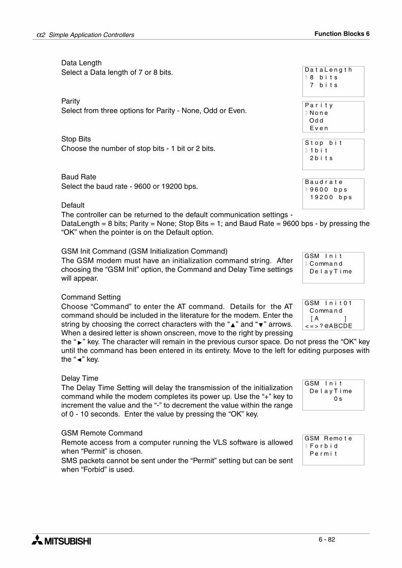
α2 Simple Application Controllers Function Blocks 6
6 - 82
Data Length Select a Data length of 7 or 8 bits.
ParitySelect from three options for Parity - None, Odd or Even.
Stop BitsChoose the number of stop bits - 1 bit or 2 bits.
Baud RateSelect the baud rate - 9600 or 19200 bps.
DefaultThe controller can be returned to the default communication settings -DataLength = 8 bits; Parity = None; Stop Bits = 1; and Baud Rate = 9600 bps - by pressing the“OK” when the pointer is on the Default option.
GSM Init Command (GSM Initialization Command)The GSM modem must have an initialization command string. Afterchoosing the “GSM Init” option, the Command and Delay Time settingswill appear.
Command Setting Choose “Command” to enter the AT command. Details for the ATcommand should be included in the literature for the modem. Enter thestring by choosing the correct characters with the “ ” and “ ” arrows.When a desired letter is shown onscreen, move to the right by pressingthe “ ” key. The character will remain in the previous cursor space. Do not press the “OK” keyuntil the command has been entered in its entirety. Move to the left for editing purposes withthe “ ” key.
Delay TimeThe Delay Time Setting will delay the transmission of the initializationcommand while the modem completes its power up. Use the “+” key toincrement the value and the “-” to decrement the value within the rangeof 0 - 10 seconds. Enter the value by pressing the “OK” key.
GSM Remote CommandRemote access from a computer running the VLS software is allowedwhen “Permit” is chosen. SMS packets cannot be sent under the “Permit” setting but can be sentwhen “Forbid” is used.
8 b i t sD a t a L e n g t h
7 b i t s
P a r i t yN o n
E v eOd d
e
n
S t o p b t1 b i
it
2 b i t s
B a u d r a e9 6 0 b p
t0 s
1 9 2 b p0 s0
GSM I i tnC omma n dD e l a y T i me
GSMC omma n d[ A ]= > ? ABCDE
I n i t 0 1
< @
GSM I n i tD e l a y T i me
0 s
F b i dGSM R emo t e
o rP m i te r
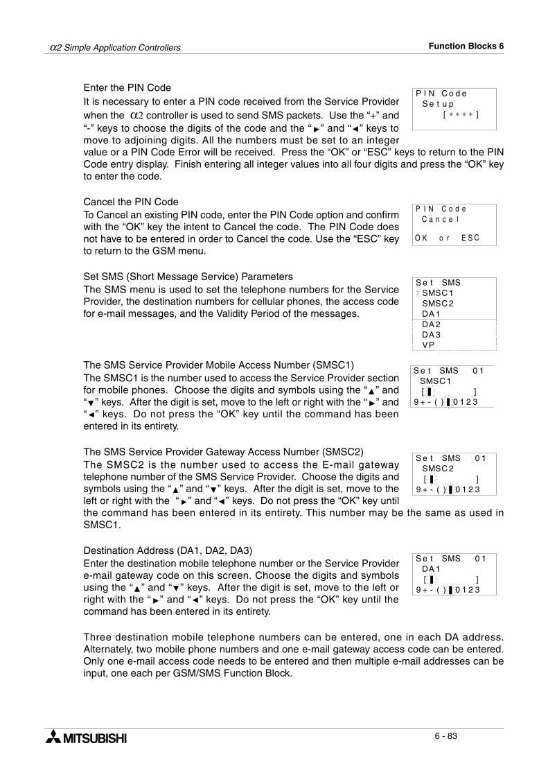
α2 Simple Application Controllers Function Blocks 6
6 - 83
Enter the PIN Code It is necessary to enter a PIN code received from the Service Providerwhen the α2 controller is used to send SMS packets. Use the “+” and“-” keys to choose the digits of the code and the “ ” and “ ” keys tomove to adjoining digits. All the numbers must be set to an integervalue or a PIN Code Error will be received. Press the “OK” or “ESC” keys to return to the PINCode entry display. Finish entering all integer values into all four digits and press the “OK” keyto enter the code.
Cancel the PIN CodeTo Cancel an existing PIN code, enter the PIN Code option and confirmwith the “OK” key the intent to Cancel the code. The PIN Code doesnot have to be entered in order to Cancel the code. Use the “ESC” keyto return to the GSM menu.
Set SMS (Short Message Service) ParametersThe SMS menu is used to set the telephone numbers for the ServiceProvider, the destination numbers for cellular phones, the access codefor e-mail messages, and the Validity Period of the messages.
The SMS Service Provider Mobile Access Number (SMSC1)The SMSC1 is the number used to access the Service Provider sectionfor mobile phones. Choose the digits and symbols using the “ ” and“ ” keys. After the digit is set, move to the left or right with the “ ” and“ ” keys. Do not press the “OK” key until the command has beenentered in its entirety.
The SMS Service Provider Gateway Access Number (SMSC2)The SMSC2 is the number used to access the E-mail gatewaytelephone number of the SMS Service Provider. Choose the digits andsymbols using the “ ” and “ ” keys. After the digit is set, move to theleft or right with the “ ” and “ ” keys. Do not press the “OK” key untilthe command has been entered in its entirety. This number may be the same as used inSMSC1.
Destination Address (DA1, DA2, DA3)Enter the destination mobile telephone number or the Service Providere-mail gateway code on this screen. Choose the digits and symbolsusing the “ ” and “ ” keys. After the digit is set, move to the left orright with the “ ” and “ ” keys. Do not press the “OK” key until thecommand has been entered in its entirety.
Three destination mobile telephone numbers can be entered, one in each DA address.Alternately, two mobile phone numbers and one e-mail gateway access code can be entered.Only one e-mail access code needs to be entered and then multiple e-mail addresses can beinput, one each per GSM/SMS Function Block.
P I N C o eS e t p
[ ∗
du
∗ ∗ ∗ ]
P I N C o eC a n e
dc l
O K o r E S C
S e t SMSMS 1
SC
SMS 2CDA 1DA 2DA 3VP
S e t SMSMS 1
SC
0 1
[ ]9 + - ) 0 3( 1 2
S e t SMSSMSC 2
10
[ ]9 + - ) 0 3( 1 2
S e t SMSDA 1
10
[ ]9 + - ) 0 3( 1 2
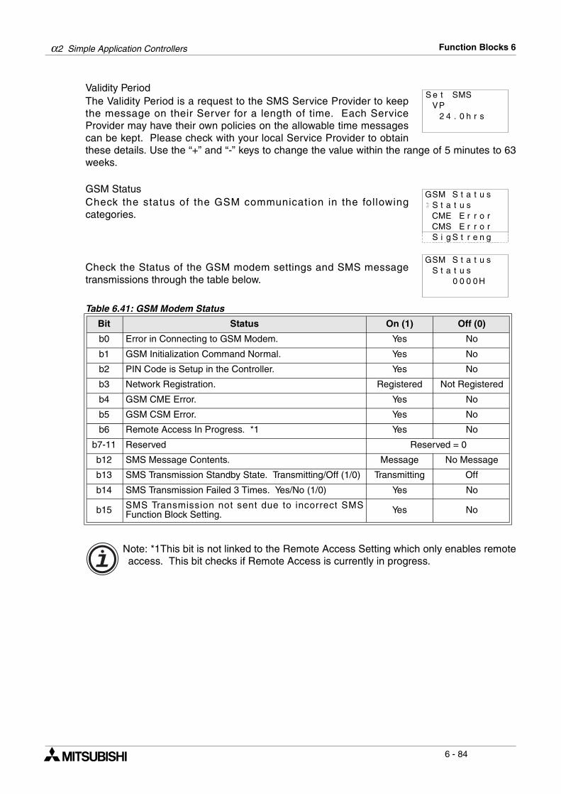
α2 Simple Application Controllers Function Blocks 6
6 - 84
Validity PeriodThe Validity Period is a request to the SMS Service Provider to keepthe message on their Server for a length of time. Each ServiceProvider may have their own policies on the allowable time messagescan be kept. Please check with your local Service Provider to obtainthese details. Use the “+” and “-” keys to change the value within the range of 5 minutes to 63weeks.
GSM Status Check the status of the GSM communication in the followingcategories.
Check the Status of the GSM modem settings and SMS messagetransmissions through the table below.
Note: *1This bit is not linked to the Remote Access Setting which only enables remoteaccess. This bit checks if Remote Access is currently in progress.
Table 6.41: GSM Modem Status
Bit Status On (1) Off (0)
b0 Error in Connecting to GSM Modem. Yes No
b1 GSM Initialization Command Normal. Yes No
b2 PIN Code is Setup in the Controller. Yes No
b3 Network Registration. Registered Not Registered
b4 GSM CME Error. Yes No
b5 GSM CSM Error. Yes No
b6 Remote Access In Progress. *1 Yes No
b7-11 Reserved Reserved = 0
b12 SMS Message Contents. Message No Message
b13 SMS Transmission Standby State. Transmitting/Off (1/0) Transmitting Off
b14 SMS Transmission Failed 3 Times. Yes/No (1/0) Yes No
b15 SMS Transmission not sent due to incorrect SMSFunction Block Setting. Yes No
VS e t SMS
P. 0 h2 4 r s
GSM S t
CME
a t u sS t a t u s
E r r o rCMS E r r o rS i g t r e n gS
GSM S t ta suS t ta su
0 00 H0

α2 Simple Application Controllers Function Blocks 6
6 - 85
CME ErrorThis CME Error status gives information to the functioning of MobileEquipment (ME), please refer to the GSM modem manual for moredetails.
CMS ErrorThis value gives error information relevant to the Mobile Equipment(ME) or Network, please refer to the GSM modem manual for moredetails.
Table 6.42: Mobile Equipment Error Codes
Value Description Value Description
-1 No Error 17 SIM PIN2 Required
0 Phone Failure 18 SIM PUK2 Required
1 No Connection to Phone 20 Memory Full
2 Phone-Adaptor Link Reserved 21 Invalid Index
3 Operation Not Allowed 22 Not Found
4 Operation Not Supported 23 Memory Full
5 PH-SIM PIN Required 24 Text String Too Long
10 SIM Failure 25 Invalid Characters in Text String
11 SIM PIN Required 26 Dial String Too Long
12 SIM PUK Required 27 Invalid Characters in Dial String
13 SIM Failure 30 No Network Service
14 SIM Busy 31 Network Timeout
15 SIM Wrong 100 Unknown
16 Incorrect Password ...256 All other values below 256 are reserved.
Table 6.43: Mobile Equipment and Network Error Codes
Value Description Value Description
-1 No Error 315 SIM Wrong
0 - 127 GSM 04.11 Annex E-2 Values 316 SIM PUK Required
128 - 256 GSM 03.40 Subclause 9.2.3.22values 317 SIM PIN2 Required
300 ME Failure 318 SIM PUK2 Required
301 SMS Service of ME reserved 320 Memory Failure
302 Operation Not Allowed 321 Invalid Memory Index
303 Operation Not Supported 322 Memory Full
304 Invalid PDU Mode Parameter 330 SMSC Address Unknown
305 Invalid Text Mode Parameter 331 No Network Service
310 SIM not Inserted 332 Network Timeout
311 SIM PIN Required 340 No +CNMA acknowledgment expected
312 PH-SIM PIN Required 500 Unknown Error
313 SIM Failure ... 511 Unused Values in the range from 256 to 511are Reserved.
314 SIM Busy 512 (+) Manufacturer Specific
GSM S t ta suCME rE
1-r o r
GSM S t ta suCMS rE
1-r o r
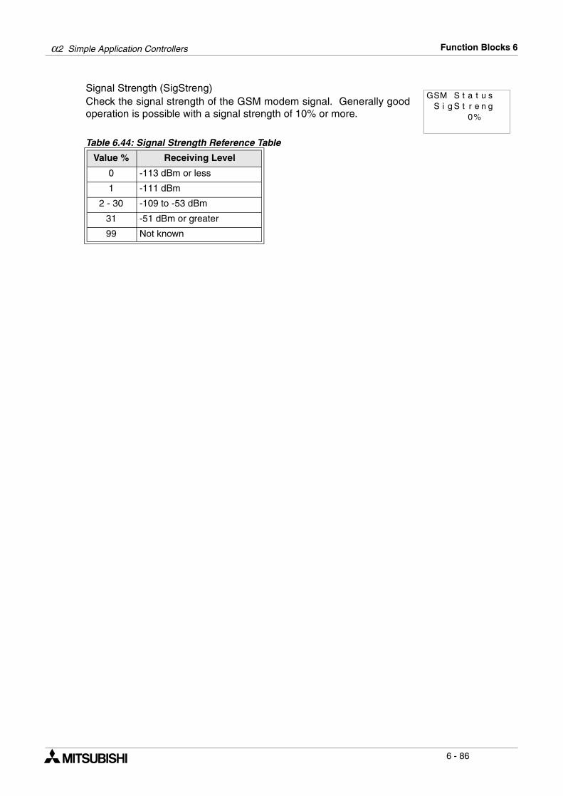
α2 Simple Application Controllers Function Blocks 6
6 - 86
Signal Strength (SigStreng)Check the signal strength of the GSM modem signal. Generally goodoperation is possible with a signal strength of 10% or more.
Table 6.44: Signal Strength Reference Table
Value % Receiving Level
0 -113 dBm or less
1 -111 dBm
2 - 30 -109 to -53 dBm
31 -51 dBm or greater
99 Not known
S i g S t r e0
GSM S t ta sun g
%

α2 Simple Application Controllers Function Blocks 6
6 - 87
6.31 Random One Shot Block
This Function Block is equivalent to the One Shot function block except that the new block hasonly randomly generated pulse time. An Upper and Lower Time Limit value can be set inincrements of 10 ms (0.00 to 327.67 seconds), 100 ms (00.0 - 3267.7 seconds), and 1 second(0 - 32767 seconds) for the random number generation. If the Input signal turns Off during thepulse interval, the Output is Reset along with the pulse time. Table 6.45: Random One Shot function block
Note: The set time cannot be less than one scan time for the controller; otherwise, theRandom One Shot Function Block will not perform its assigned task for the timespecified. Users can monitor the scan time from the α2 Series Controller. Scan timeis dependent on the user- program; therefore, caution is needed as and when timeunits are selected.
Setup of the Random One Shot Function Block directly from the α2 Series Controller1 ) Allocate the input pin to be used for the function block.
2 ) Press the “OK” key with the cursor in the function block. The function block edit screen is displayed as shown.
Function Set Item Description
I Input pin for the random one shot function block
C Clear pin for the random one shot function block
FB
1) A random one shot time is generated between the upper and lowerthreshold values.
2) The random value only occurs in correlation to the ON status of theinput.
3) The clear signal input reset the output, random one shot value andcurrent time.
4) If the Upper threshold is equal to or larger than the lower threshold,the random one shot time is set in the range lower threshold to upperthreshold.
5) If the Upper threshold is less then than the lower threshold, therandom one shot time is set in the range 0 to upper threshold or lowerthreshold to 32767.
6) If the lower threshold = Upper threshold, the random one shot isequal to the upper threshold = lower threshold.
7) Time units: 10ms, 100ms or 1s (*Note)
Output1) The following items are available for other function blocks: a) Random One Shot value b) Current One Shot value
0 00
OR
OI
SC
P
T i me u n iB 0 0 1 : R
C h a n g e N oD e l e t e F B
SOt
S e t u p F B
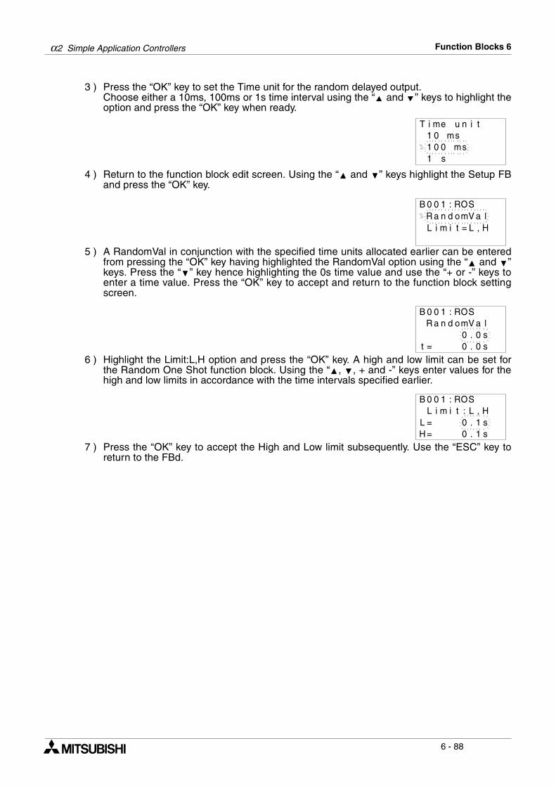
α2 Simple Application Controllers Function Blocks 6
6 - 88
3 ) Press the “OK” key to set the Time unit for the random delayed output.Choose either a 10ms, 100ms or 1s time interval using the “ and ” keys to highlight theoption and press the “OK” key when ready.
4 ) Return to the function block edit screen. Using the “ and ” keys highlight the Setup FBand press the “OK” key.
5 ) A RandomVal in conjunction with the specified time units allocated earlier can be enteredfrom pressing the “OK” key having highlighted the RandomVal option using the “ and ”keys. Press the “ ” key hence highlighting the 0s time value and use the “+ or -” keys toenter a time value. Press the “OK” key to accept and return to the function block settingscreen.
6 ) Highlight the Limit:L,H option and press the “OK” key. A high and low limit can be set forthe Random One Shot function block. Using the “ , , + and -” keys enter values for thehigh and low limits in accordance with the time intervals specified earlier.
7 ) Press the “OK” key to accept the High and Low limit subsequently. Use the “ESC” key toreturn to the FBd.
T i me u n i t
1 0 0 sm1 0 ms
1 s
B 0 0 1 : R SOR a n d o Vm a lL i m i t L= , H
B 0 0 1 : R SOR a n d o Vm a l
.0 0 st = .0 0 s
B 0 0 1 : R SOL i m i t L: , H
.0 1 sL= .0 1 sH=
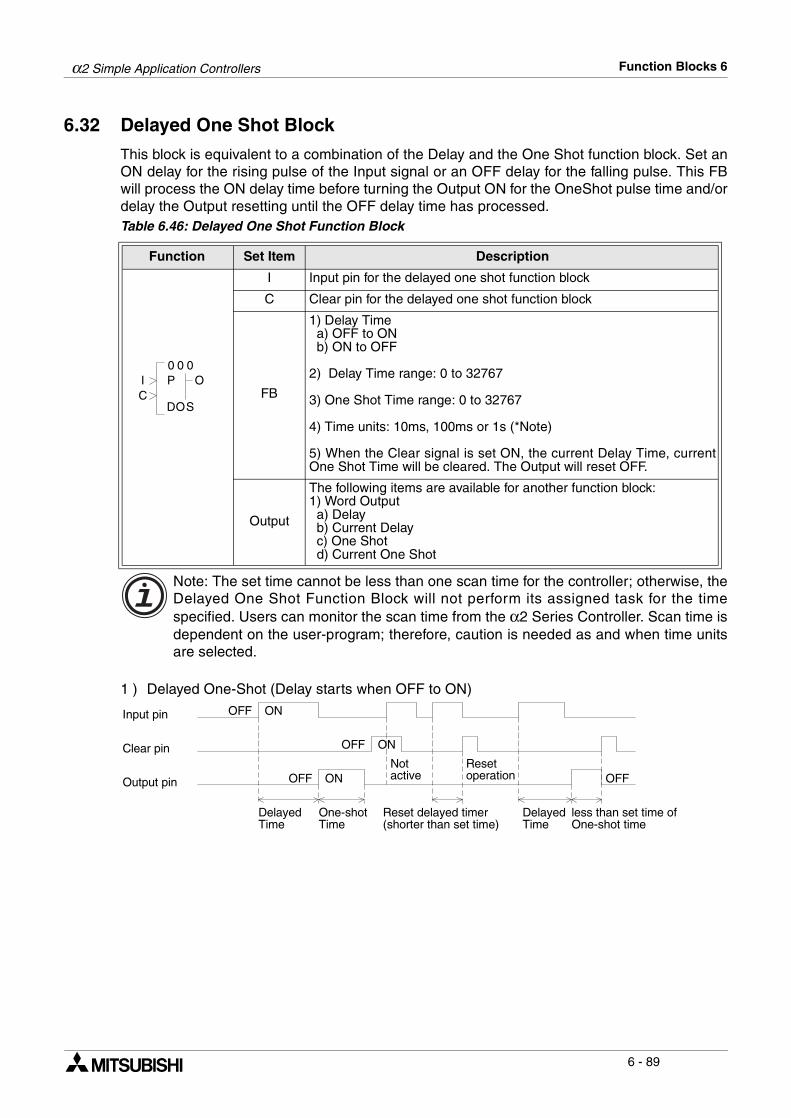
α2 Simple Application Controllers Function Blocks 6
6 - 89
6.32 Delayed One Shot Block
This block is equivalent to a combination of the Delay and the One Shot function block. Set anON delay for the rising pulse of the Input signal or an OFF delay for the falling pulse. This FBwill process the ON delay time before turning the Output ON for the OneShot pulse time and/ordelay the Output resetting until the OFF delay time has processed. Table 6.46: Delayed One Shot Function Block
Note: The set time cannot be less than one scan time for the controller; otherwise, theDelayed One Shot Function Block will not perform its assigned task for the timespecified. Users can monitor the scan time from the α2 Series Controller. Scan time isdependent on the user-program; therefore, caution is needed as and when time unitsare selected.
1 ) Delayed One-Shot (Delay starts when OFF to ON)
Function Set Item Description
I Input pin for the delayed one shot function block
C Clear pin for the delayed one shot function block
FB
1) Delay Time a) OFF to ON b) ON to OFF
2) Delay Time range: 0 to 32767
3) One Shot Time range: 0 to 32767
4) Time units: 10ms, 100ms or 1s (*Note)
5) When the Clear signal is set ON, the current Delay Time, currentOne Shot Time will be cleared. The Output will reset OFF.
Output
The following items are available for another function block:1) Word Output a) Delay b) Current Delay c) One Shot d) Current One Shot
0 00
OD
OI
SC
P
Input pin OFF ON
Clear pin
OFF ON
OFF ON
Notactive
Resetoperation OFFOutput pin
DelayedTime
One-shotTime
Reset delayed timer(shorter than set time)
DelayedTime
less than set time ofOne-shot time
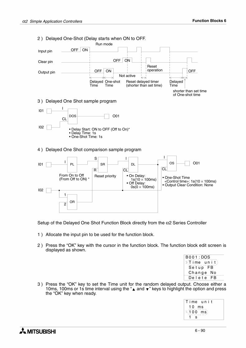
α2 Simple Application Controllers Function Blocks 6
6 - 90
2 ) Delayed One-Shot (Delay starts when ON to OFF.
3 ) Delayed One Shot sample program
4 ) Delayed One Shot comparison sample program
Setup of the Delayed One Shot Function Block directly from the α2 Series Controller
1 ) Allocate the input pin to be used for the function block.
2 ) Press the “OK” key with the cursor in the function block. The function block edit screen isdisplayed as shown.
3 ) Press the “OK” key to set the Time unit for the random delayed output. Choose either a10ms, 100ms or 1s time interval using the “ and ” keys to highlight the option and pressthe “OK” key when ready.
Input pin OFF ON
Clear pin
Run mode
OFF ON
OFF ON
Not active
Resetoperation OFFOutput pin
DelayedTime
One-shotTime
Reset delayed timer(shorter than set time)
DelayedTime
shorter than set timeof One-shot time
I01
I02
DOS O01
I
CL
• Delay Start: ON to OFF (Off to On)*• Delay Time: 1s• One-Shot Time: 1s
I01
I02
PLI
• On Delay: 1s(10 × 100ms)• Off Delay: 0s(0 × 100ms)
SR
S
R
DL
I
CL
OS O01
OR
From On to Off(From Off to ON) *
Reset priority
CL
I
1
2
• One-Shot Time <Control time>: 1s(10 × 100ms)• Output Clear Condition: None
B 0 0 1 : D SOT i me u n i
C h a n g e N oD e l e t e F B
tS e t u p F B
T i me u n i t
1 0 0 sm1 0 ms
1 s

α2 Simple Application Controllers Function Blocks 6
6 - 91
4 ) Return to the function block edit screen. Using the “Up and Down” keys to highlight theSetup FB and press the “OK” key.
5 ) Highlight DelayTime from the list of options and press the “OK” key. The Delay Time canbe entered using the “ , , + and -” keys.
6 ) Highlight OneShot from the list of options and press the “OK” key to enter times. The OneShot Time can be entered using the “ , , + and -” keys.
7 ) Highlight Condition from the list of options and press the “OK” key to enter either aRiseEdge or a FallEdge for the Delayed One Shot Operation.
8 ) Press the “OK” key to accept and use the “ESC” key to return to the FBd.
D e l y T mi eO n e S h to
B 0 0 1 : D SO
C o n d i it no
a
D e l a y it me.0 1 s
t = .0 0 s
B 0 0 1 : D SO
T =
O n e s h to.0 1 s
t = .0 1 sT =
B 0 0 1 : D SO
R i s e E gd
B 0 0 1 : D SOC o n d i it no
eF a l l E gd e
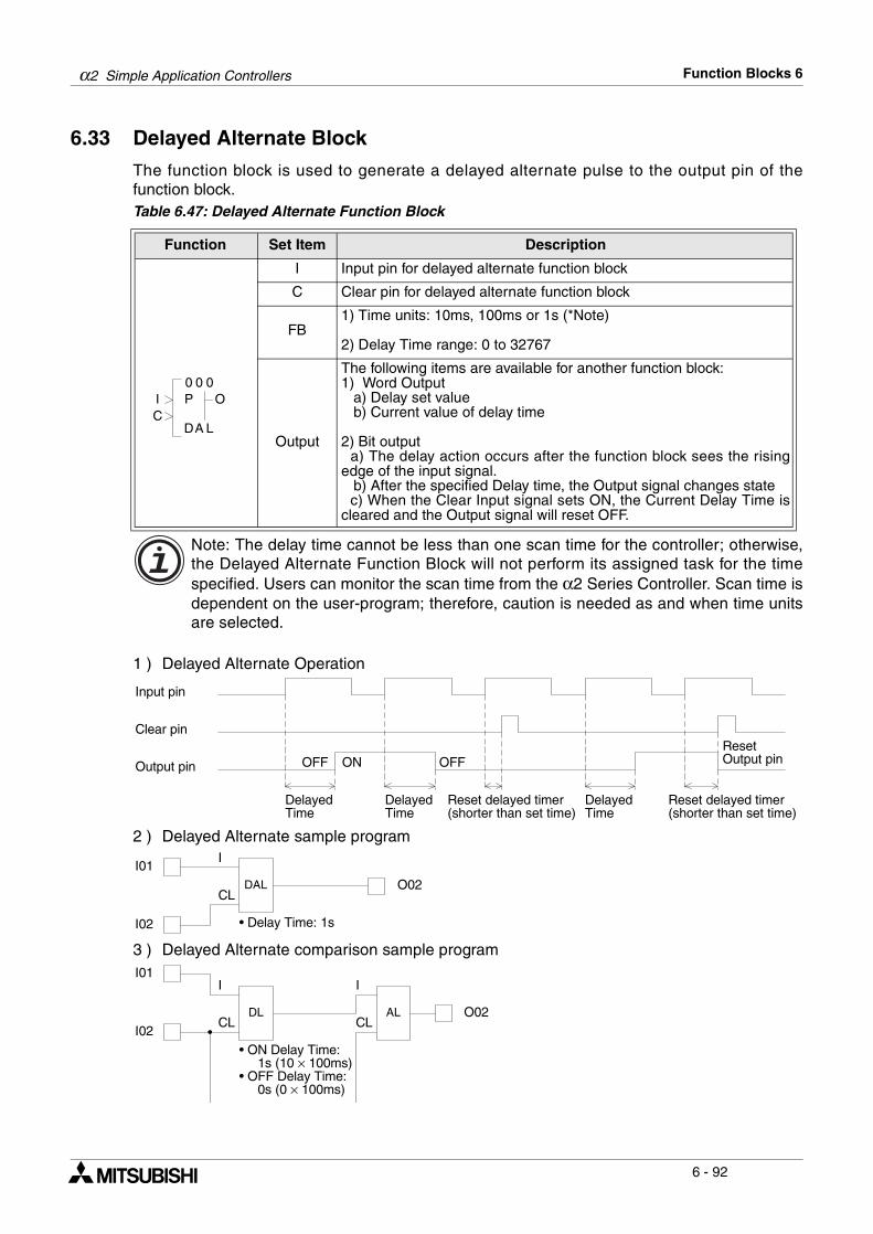
α2 Simple Application Controllers Function Blocks 6
6 - 92
6.33 Delayed Alternate Block
The function block is used to generate a delayed alternate pulse to the output pin of thefunction block.Table 6.47: Delayed Alternate Function Block
Note: The delay time cannot be less than one scan time for the controller; otherwise,the Delayed Alternate Function Block will not perform its assigned task for the timespecified. Users can monitor the scan time from the α2 Series Controller. Scan time isdependent on the user-program; therefore, caution is needed as and when time unitsare selected.
1 ) Delayed Alternate Operation
2 ) Delayed Alternate sample program
3 ) Delayed Alternate comparison sample program
Function Set Item Description
I Input pin for delayed alternate function block
C Clear pin for delayed alternate function block
FB1) Time units: 10ms, 100ms or 1s (*Note)
2) Delay Time range: 0 to 32767
Output
The following items are available for another function block:1) Word Output a) Delay set value b) Current value of delay time
2) Bit output a) The delay action occurs after the function block sees the risingedge of the input signal. b) After the specified Delay time, the Output signal changes state c) When the Clear Input signal sets ON, the Current Delay Time iscleared and the Output signal will reset OFF.
0 00
AD
OI
LC
P
Input pin
Clear pin
OFF ONOutput pin
DelayedTime
Reset delayed timer(shorter than set time)
DelayedTime
DelayedTime
Reset delayed timer(shorter than set time)
ResetOutput pinOFF
I01
I02
DAL O02
I
CL
• Delay Time: 1s
I01
I02
DL O02
I
CL
• ON Delay Time: 1s (10 × 100ms)• OFF Delay Time: 0s (0 × 100ms)
AL
I
CL
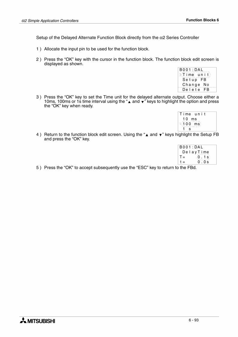
α2 Simple Application Controllers Function Blocks 6
6 - 93
Setup of the Delayed Alternate Function Block directly from the α2 Series Controller
1 ) Allocate the input pin to be used for the function block.
2 ) Press the “OK” key with the cursor in the function block. The function block edit screen isdisplayed as shown.
3 ) Press the “OK” key to set the Time unit for the delayed alternate output. Choose either a10ms, 100ms or 1s time interval using the “ and ” keys to highlight the option and pressthe “OK” key when ready.
4 ) Return to the function block edit screen. Using the “ and ” keys highlight the Setup FBand press the “OK” key.
5 ) Press the “OK” to accept subsequently use the “ESC” key to return to the FBd.
B 0 0 1 : D LAT i me u n i
C h a n g e N oD e l e t e F B
tS e t u p F B
T i me u n i t
1 0 0 sm1 0 ms
1 s
D e l a y iT me.0 1 s
t = .0 0 sT =
B 0 0 1 : D LA
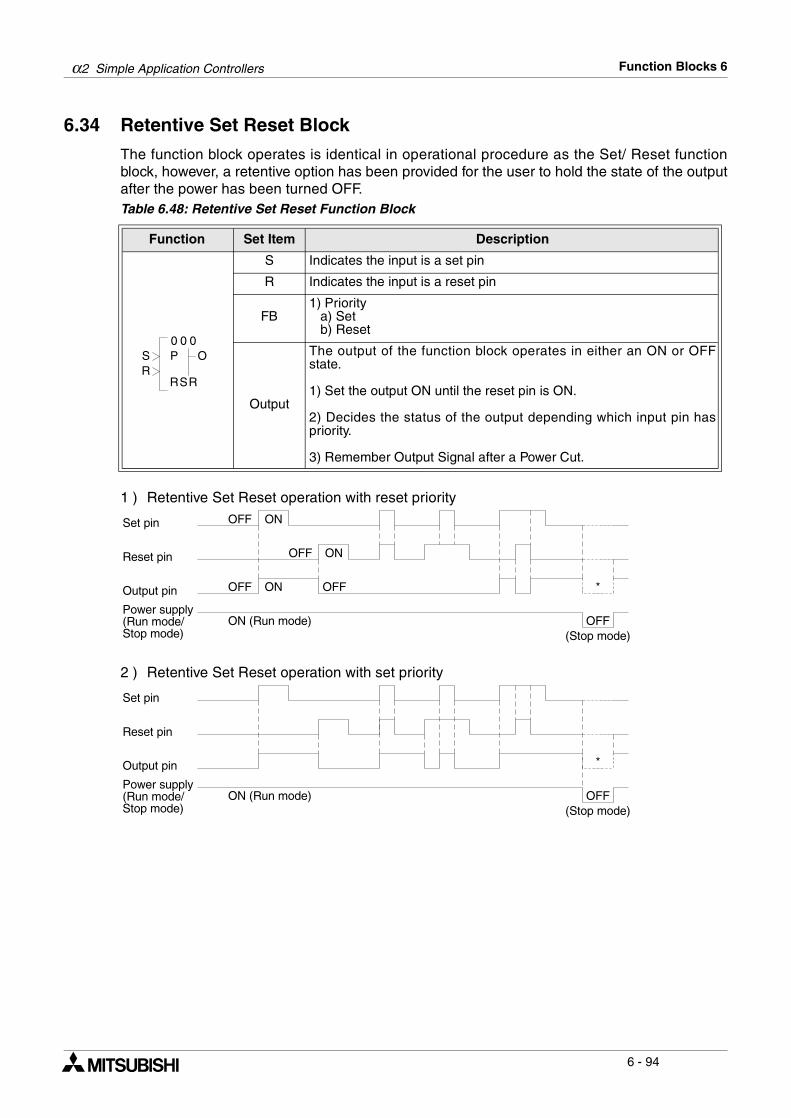
α2 Simple Application Controllers Function Blocks 6
6 - 94
6.34 Retentive Set Reset Block
The function block operates is identical in operational procedure as the Set/ Reset functionblock, however, a retentive option has been provided for the user to hold the state of the outputafter the power has been turned OFF.Table 6.48: Retentive Set Reset Function Block
1 ) Retentive Set Reset operation with reset priority
2 ) Retentive Set Reset operation with set priority
Function Set Item Description
S Indicates the input is a set pin
R Indicates the input is a reset pin
FB1) Priority a) Set b) Reset
Output
The output of the function block operates in either an ON or OFFstate.
1) Set the output ON until the reset pin is ON.
2) Decides the status of the output depending which input pin haspriority.
3) Remember Output Signal after a Power Cut.
0 00
SR
OSR
R
P
Set pin
OFF ONReset pin
OFF ON *Output pin OFF
OFFON (Run mode)Power supply(Run mode/Stop mode) (Stop mode)
OFF ON
Set pin
Reset pin
*Output pin
OFFON (Run mode)Power supply(Run mode/Stop mode) (Stop mode)
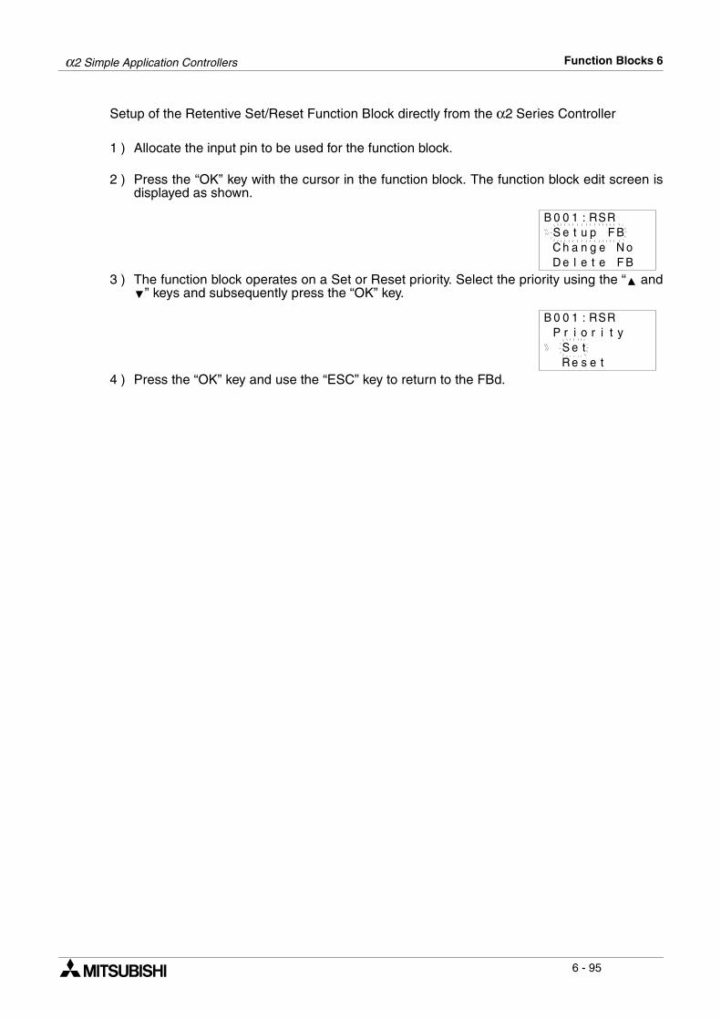
α2 Simple Application Controllers Function Blocks 6
6 - 95
Setup of the Retentive Set/Reset Function Block directly from the α2 Series Controller
1 ) Allocate the input pin to be used for the function block.
2 ) Press the “OK” key with the cursor in the function block. The function block edit screen isdisplayed as shown.
3 ) The function block operates on a Set or Reset priority. Select the priority using the “ and” keys and subsequently press the “OK” key.
4 ) Press the “OK” key and use the “ESC” key to return to the FBd.
B 0 0 1 : RSS e t u p F BC h a n g e N oD e l e t e F B
R
B 0 0 1 : RS
S e tR e s e t
RP r i o r i t y
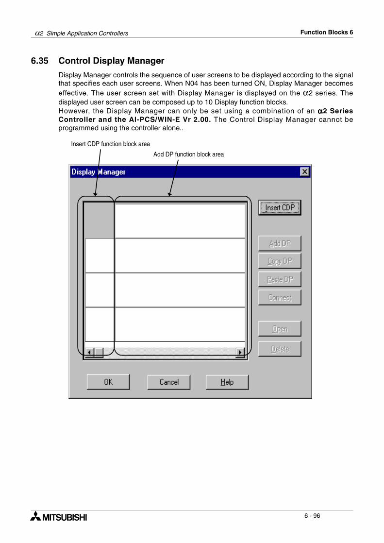
α2 Simple Application Controllers Function Blocks 6
6 - 96
6.35 Control Display Manager
Display Manager controls the sequence of user screens to be displayed according to the signalthat specifies each user screens. When N04 has been turned ON, Display Manager becomeseffective. The user screen set with Display Manager is displayed on the α2 series. Thedisplayed user screen can be composed up to 10 Display function blocks. However, the Display Manager can only be set using a combination of an αααα2 SeriesController and the Al-PCS/WIN-E Vr 2.00. The Control Display Manager cannot beprogrammed using the controller alone..
Insert CDP function block area
Add DP function block area
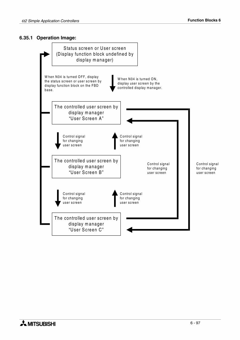
α2 Simple Application Controllers Function Blocks 6
6 - 97
6.35.1 Operation Image:
W hen N 04 is tu rned O N ,d isp lay user screen by thecontro lled d isp lay m anager.
W hen N 04 is tu rned O FF, d isp laythe s tatus screen or user screen byd isp lay function b lock on the FBDbase.
C ontro l s igna lfo r chang inguser screen
S ta tus screen o r U ser screen(D isp lay function b lock unde fined by
d isp lay m anager)
T he con tro lled user screen byd isp lay m anager“U ser S creen A ”
T he con tro lled user screen byd isp lay m anager“U ser S creen B ”
T he con tro lled user screen byd isp lay m anager“U ser S creen C ”
C ontro l s igna lfo r chang inguser screen
C ontro l s igna lfo r chang inguser screen
C ontro l s igna lfo r chang inguser screen
C ontro l s igna lfo r chang inguser screen
C ontro l s igna lfo r chang inguser screen
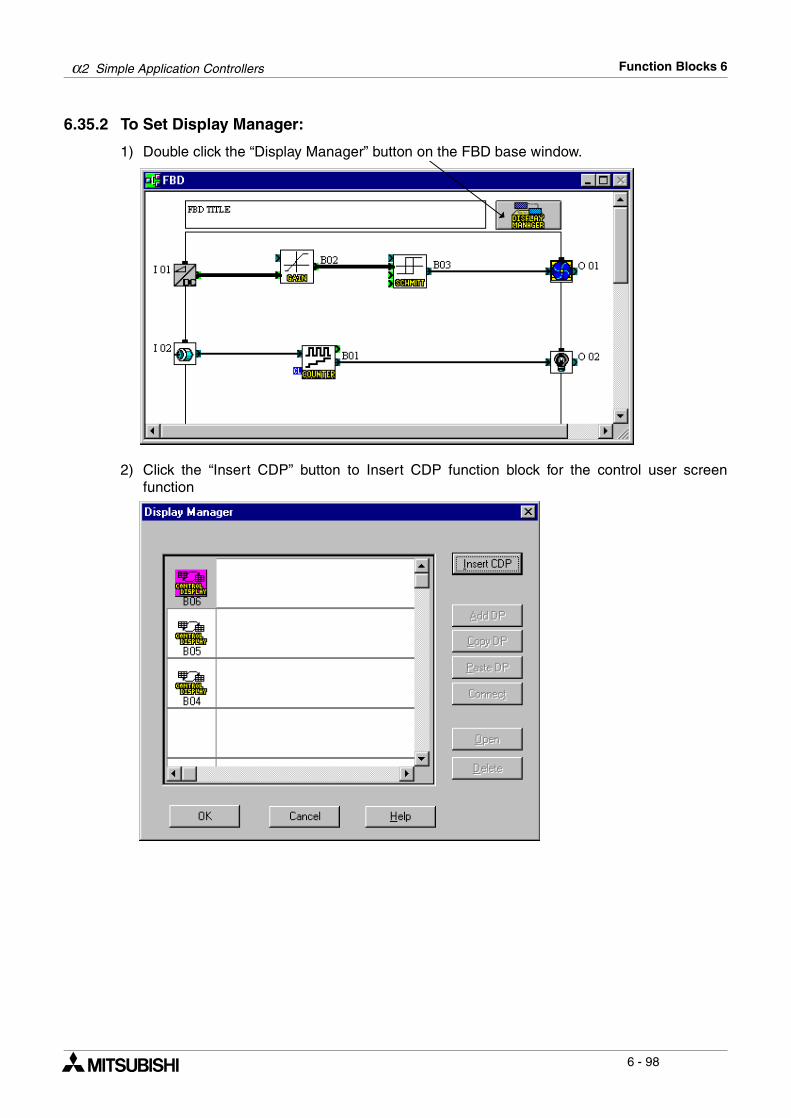
α2 Simple Application Controllers Function Blocks 6
6 - 98
6.35.2 To Set Display Manager:
1) Double click the “Display Manager” button on the FBD base window.
2) Click the “Insert CDP” button to Insert CDP function block for the control user screenfunction
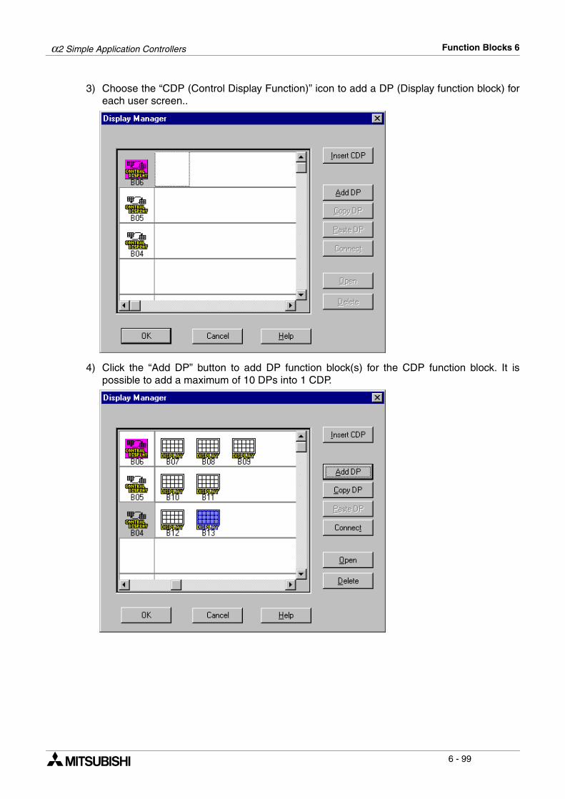
α2 Simple Application Controllers Function Blocks 6
6 - 99
3) Choose the “CDP (Control Display Function)” icon to add a DP (Display function block) foreach user screen..
4) Click the “Add DP” button to add DP function block(s) for the CDP function block. It ispossible to add a maximum of 10 DPs into 1 CDP.
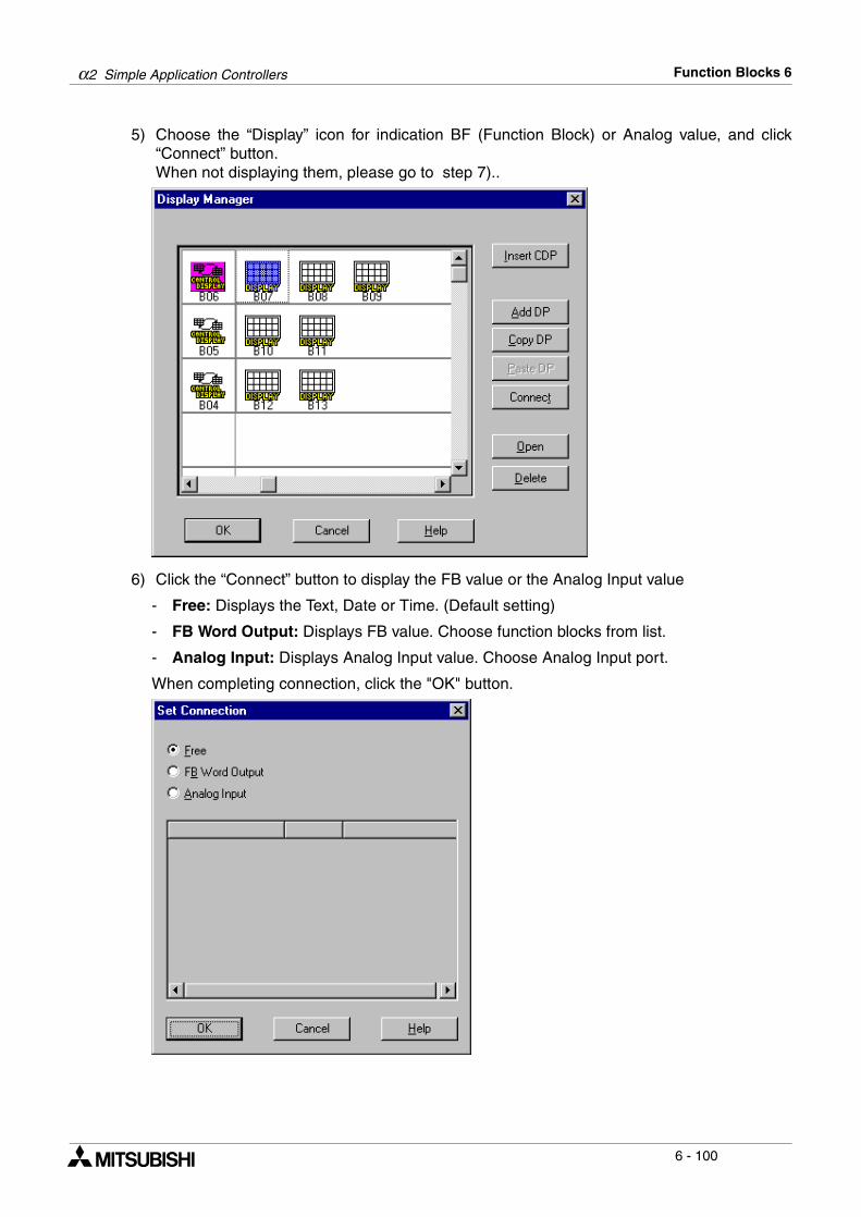
α2 Simple Application Controllers Function Blocks 6
6 - 100
5) Choose the “Display” icon for indication BF (Function Block) or Analog value, and click“Connect” button.When not displaying them, please go to step 7)..
6) Click the “Connect” button to display the FB value or the Analog Input value
- Free: Displays the Text, Date or Time. (Default setting)
- FB Word Output: Displays FB value. Choose function blocks from list.
- Analog Input: Displays Analog Input value. Choose Analog Input port.
When completing connection, click the "OK" button.
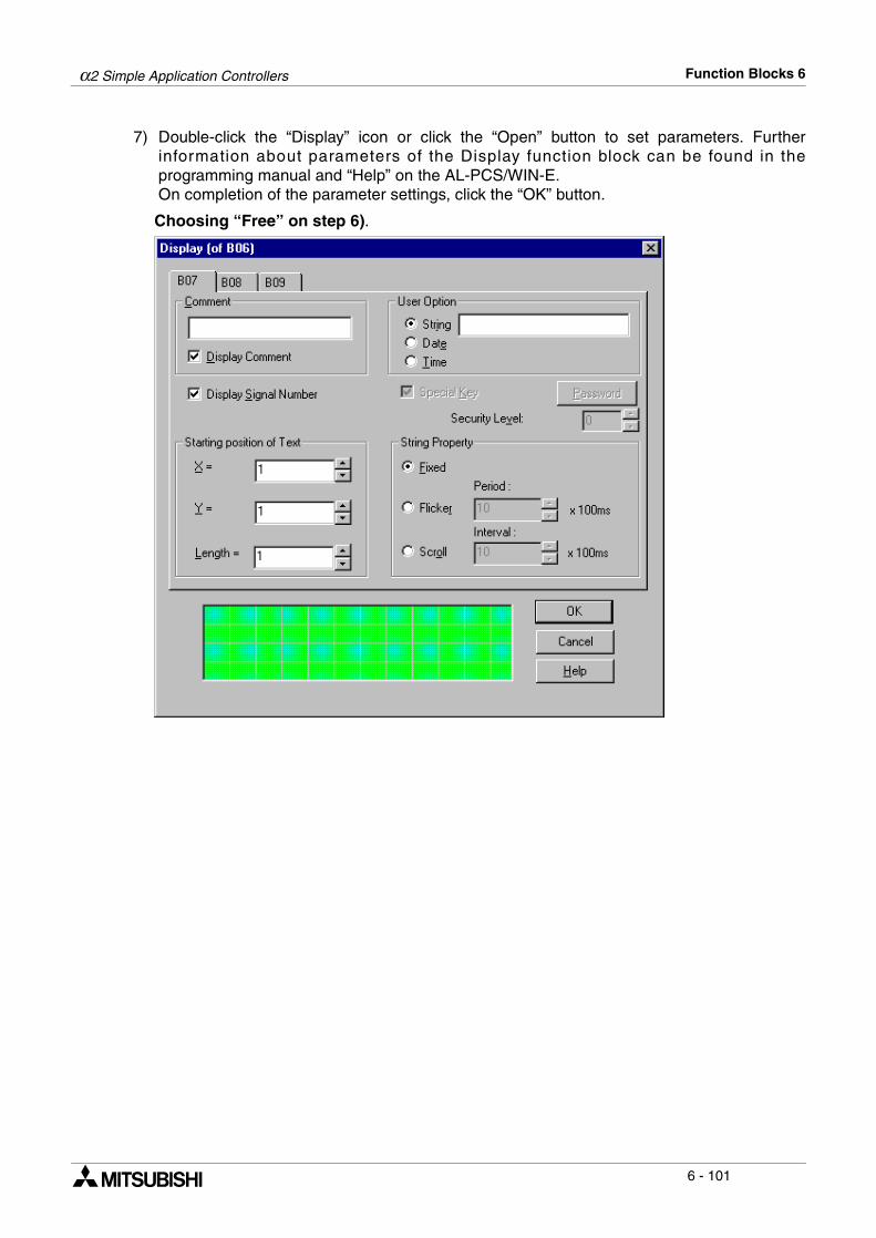
α2 Simple Application Controllers Function Blocks 6
6 - 101
7) Double-click the “Display” icon or click the “Open” button to set parameters. Furtherinformation about parameters of the Display function block can be found in theprogramming manual and “Help” on the AL-PCS/WIN-E.On completion of the parameter settings, click the “OK” button.
Choosing “Free” on step 6).
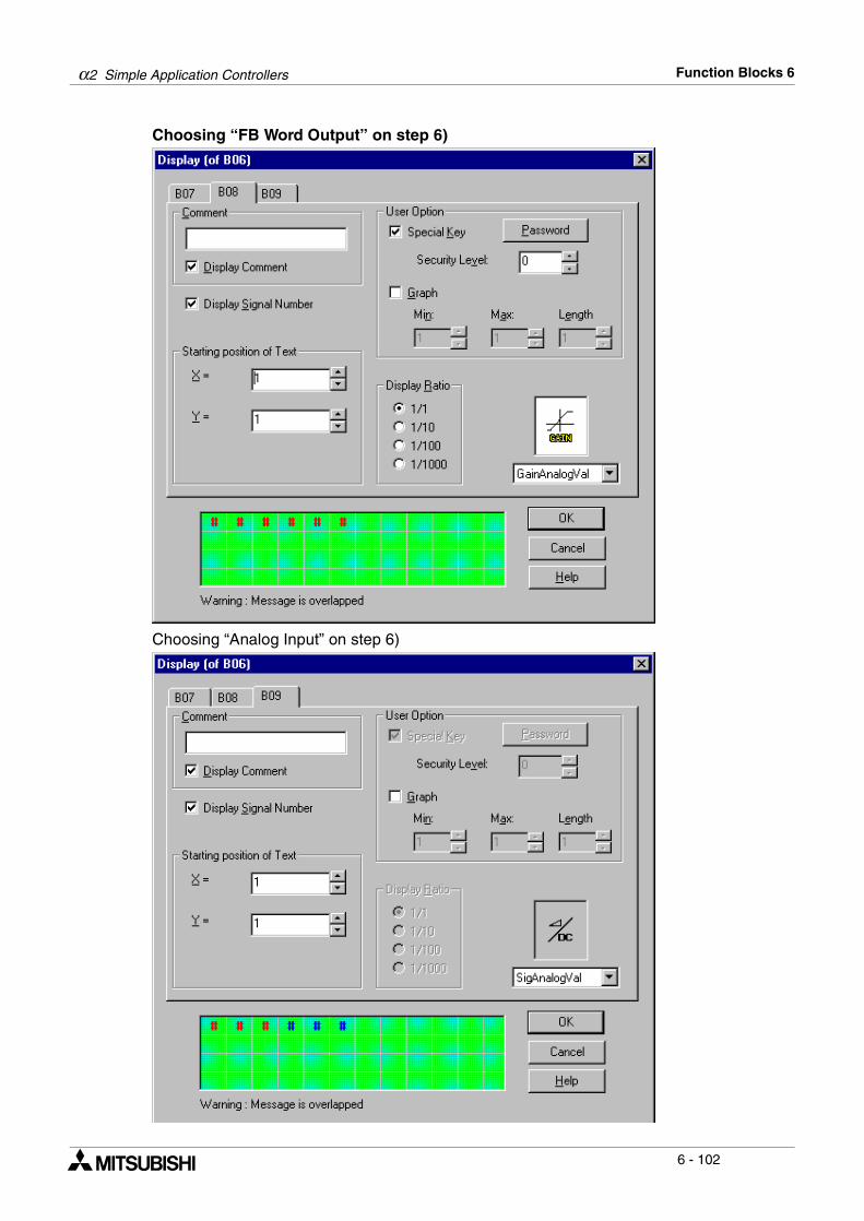
α2 Simple Application Controllers Function Blocks 6
6 - 102
Choosing “FB Word Output” on step 6)
Choosing “Analog Input” on step 6)
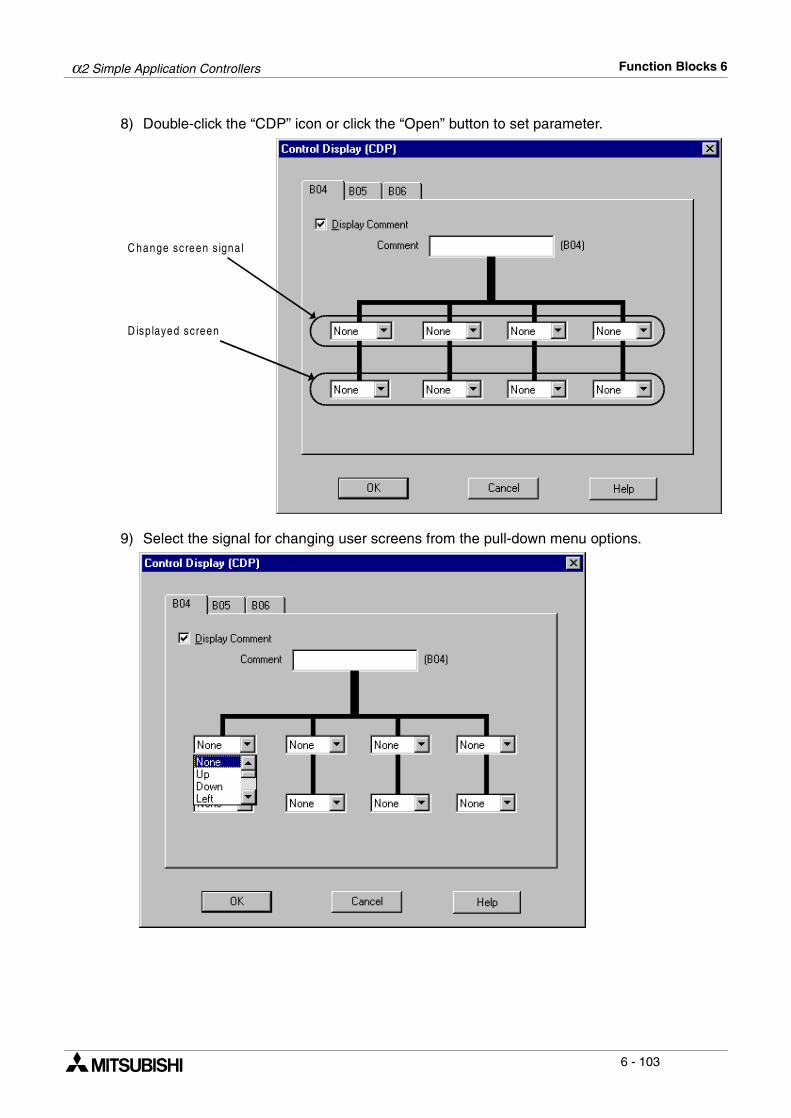
α2 Simple Application Controllers Function Blocks 6
6 - 103
8) Double-click the “CDP” icon or click the “Open” button to set parameter.
9) Select the signal for changing user screens from the pull-down menu options.
C hange screen s igna l
D isp layed screen
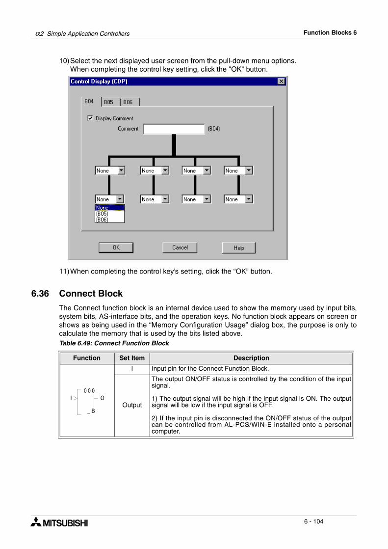
α2 Simple Application Controllers Function Blocks 6
6 - 104
10)Select the next displayed user screen from the pull-down menu options.When completing the control key setting, click the "OK" button.
11)When completing the control key’s setting, click the “OK” button.
6.36 Connect Block
The Connect function block is an internal device used to show the memory used by input bits,system bits, AS-interface bits, and the operation keys. No function block appears on screen orshows as being used in the “Memory Configuration Usage” dialog box, the purpose is only tocalculate the memory that is used by the bits listed above.Table 6.49: Connect Function Block
Function Set Item Description
I Input pin for the Connect Function Block.
Output
The output ON/OFF status is controlled by the condition of the inputsignal.
1) The output signal will be high if the input signal is ON. The outputsignal will be low if the input signal is OFF.
2) If the input pin is disconnected the ON/OFF status of the outputcan be controlled from AL-PCS/WIN-E installed onto a personalcomputer.
00
B_
OI0
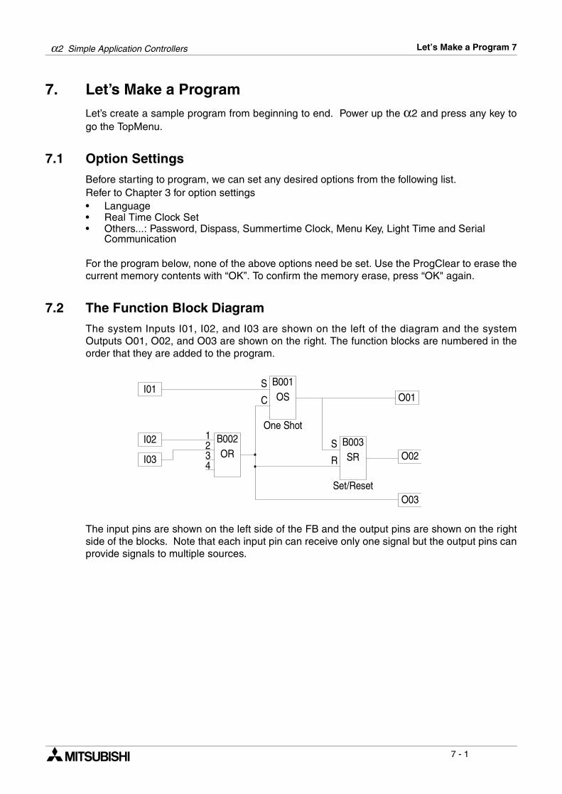
α2 Simple Application Controllers Let’s Make a Program 7
7 - 1
7. Let’s Make a ProgramLet’s create a sample program from beginning to end. Power up the α2 and press any key togo the TopMenu.
7.1 Option Settings
Before starting to program, we can set any desired options from the following list.Refer to Chapter 3 for option settings• Language• Real Time Clock Set• Others...: Password, Dispass, Summertime Clock, Menu Key, Light Time and Serial
Communication
For the program below, none of the above options need be set. Use the ProgClear to erase thecurrent memory contents with “OK”. To confirm the memory erase, press “OK" again.
7.2 The Function Block Diagram
The system Inputs I01, I02, and I03 are shown on the left of the diagram and the systemOutputs O01, O02, and O03 are shown on the right. The function blocks are numbered in theorder that they are added to the program.
The input pins are shown on the left side of the FB and the output pins are shown on the rightside of the blocks. Note that each input pin can receive only one signal but the output pins canprovide signals to multiple sources.
I01
OR
1 B002One Shot
I02
I03234
OSB001S
C
SRB003
Set/Reset
O01
O02
O03
S
R
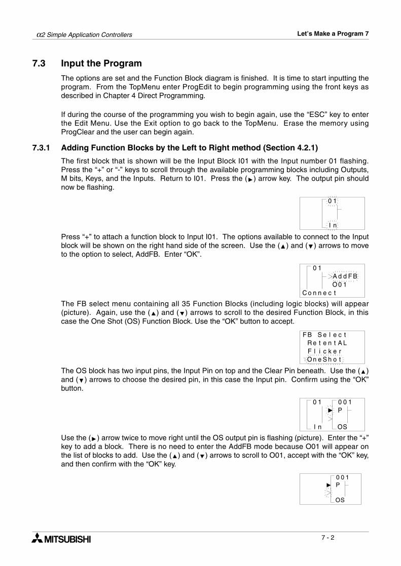
α2 Simple Application Controllers Let’s Make a Program 7
7 - 2
7.3 Input the Program
The options are set and the Function Block diagram is finished. It is time to start inputting theprogram. From the TopMenu enter ProgEdit to begin programming using the front keys asdescribed in Chapter 4 Direct Programming.
If during the course of the programming you wish to begin again, use the “ESC” key to enterthe Edit Menu. Use the Exit option to go back to the TopMenu. Erase the memory usingProgClear and the user can begin again.
7.3.1 Adding Function Blocks by the Left to Right method (Section 4.2.1)
The first block that is shown will be the Input Block I01 with the Input number 01 flashing.Press the “+” or “-” keys to scroll through the available programming blocks including Outputs,M bits, Keys, and the Inputs. Return to I01. Press the ( ) arrow key. The output pin shouldnow be flashing.
Press “+” to attach a function block to Input I01. The options available to connect to the Inputblock will be shown on the right hand side of the screen. Use the ( ) and ( ) arrows to moveto the option to select, AddFB. Enter “OK”.
The FB select menu containing all 35 Function Blocks (including logic blocks) will appear(picture). Again, use the ( ) and ( ) arrows to scroll to the desired Function Block, in thiscase the One Shot (OS) Function Block. Use the “OK” button to accept.
The OS block has two input pins, the Input Pin on top and the Clear Pin beneath. Use the ( )and ( ) arrows to choose the desired pin, in this case the Input pin. Confirm using the “OK”button.
Use the ( ) arrow twice to move right until the OS output pin is flashing (picture). Enter the “+”key to add a block. There is no need to enter the AddFB mode because O01 will appear onthe list of blocks to add. Use the ( ) and ( ) arrows to scroll to O01, accept with the “OK” key,and then confirm with the “OK” key.
1
nI
0
1
oC
0
nn ce t
dA Fd B0O 1
eleSBF tLAteeR t
kcienO
reF ln
hS to
c
10
nI
0 10P
SO
0 10P
SO
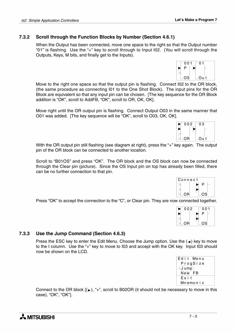
α2 Simple Application Controllers Let’s Make a Program 7
7 - 3
7.3.2 Scroll through the Function Blocks by Number (Section 4.6.1)
When the Output has been connected, move one space to the right so that the Output number“01” is flashing. Use the “+” key to scroll through to Input I02. (You will scroll through theOutputs, Keys, M bits, and finally get to the Inputs).
Move to the right one space so that the output pin is flashing. Connect I02 to the OR block,(the same procedure as connecting I01 to the One Shot Block). The input pins for the ORBlock are equivalent so that any input pin can be chosen. [The key sequence for the OR Blockaddition is “OK”, scroll to AddFB, “OK”, scroll to OR, OK, OK].
Move right until the OR output pin is flashing. Connect Output O03 in the same manner thatO01 was added. [The key sequence will be “OK”, scroll to O03, OK, OK].
With the OR output pin still flashing (see diagram at right), press the “+” key again. The outputpin of the OR block can be connected to another location.
Scroll to “B01OS” and press “OK”. The OR block and the OS block can now be connectedthrough the Clear pin (picture). Since the OS Input pin on top has already been filled, therecan be no further connection to that pin.
Press “OK” to accept the connection to the “C”, or Clear pin. They are now connected together.
7.3.3 Use the Jump Command (Section 4.6.3)
Press the ESC key to enter the Edit Menu. Choose the Jump option. Use the ( ) key to moveto the I column. Use the “+” key to move to I03 and accept with the OK key. Input I03 shouldnow be shown on the LCD.
Connect to the OR block [( ), “+”, scroll to B02OR (it should not be necessary to move in thiscase), “OK”, “OK”].
00
SO
0 1
uO
1P
t
00
RO
0 3
uO
2
t
nn
RO
P
SO
oC tce
00
RO
P
SO
2 00 1
eM unezi
tdE i
pmweN
J uSgorP
ixE tBF
cinomenM
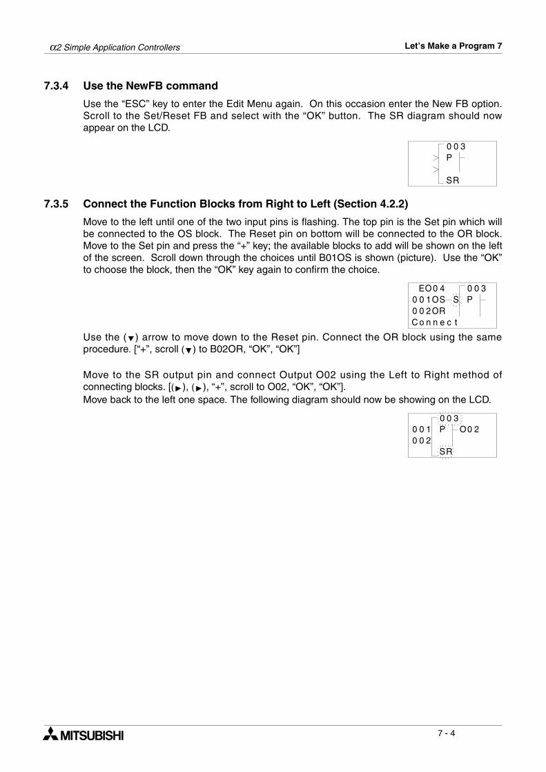
α2 Simple Application Controllers Let’s Make a Program 7
7 - 4
7.3.4 Use the NewFB command
Use the “ESC” key to enter the Edit Menu again. On this occasion enter the New FB option.Scroll to the Set/Reset FB and select with the “OK” button. The SR diagram should nowappear on the LCD.
7.3.5 Connect the Function Blocks from Right to Left (Section 4.2.2)
Move to the left until one of the two input pins is flashing. The top pin is the Set pin which willbe connected to the OS block. The Reset pin on bottom will be connected to the OR block.Move to the Set pin and press the “+” key; the available blocks to add will be shown on the leftof the screen. Scroll down through the choices until B01OS is shown (picture). Use the “OK”to choose the block, then the “OK” key again to confirm the choice.
Use the ( ) arrow to move down to the Reset pin. Connect the OR block using the sameprocedure. [“+”, scroll ( ) to B02OR, “OK”, “OK”]
Move to the SR output pin and connect Output O02 using the Left to Right method ofconnecting blocks. [( ), ( ), “+”, scroll to O02, “OK”, “OK”].Move back to the left one space. The following diagram should now be showing on the LCD.
0
RS
0 3P
0O 0 30S
E 4100 OS200 ORnoC n e c t
P
0
RS
000 100 2
P3
0O 2
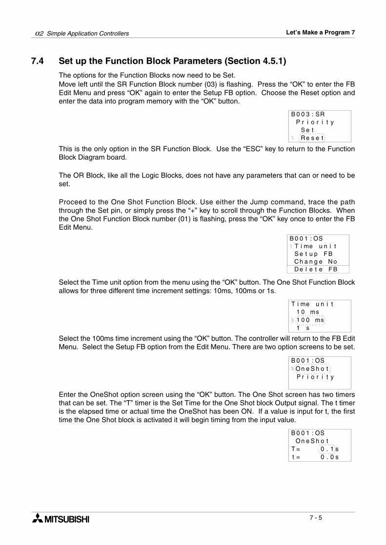
α2 Simple Application Controllers Let’s Make a Program 7
7 - 5
7.4 Set up the Function Block Parameters (Section 4.5.1)
The options for the Function Blocks now need to be Set.Move left until the SR Function Block number (03) is flashing. Press the “OK” to enter the FBEdit Menu and press “OK” again to enter the Setup FB option. Choose the Reset option andenter the data into program memory with the “OK” button.
This is the only option in the SR Function Block. Use the “ESC” key to return to the FunctionBlock Diagram board.
The OR Block, like all the Logic Blocks, does not have any parameters that can or need to beset.
Proceed to the One Shot Function Block. Use either the Jump command, trace the paththrough the Set pin, or simply press the “+” key to scroll through the Function Blocks. Whenthe One Shot Function Block number (01) is flashing, press the “OK” key once to enter the FBEdit Menu.
Select the Time unit option from the menu using the “OK” button. The One Shot Function Blockallows for three different time increment settings: 10ms, 100ms or 1s.
Select the 100ms time increment using the “OK” button. The controller will return to the FB EditMenu. Select the Setup FB option from the Edit Menu. There are two option screens to be set.
Enter the OneShot option screen using the “OK” button. The One Shot screen has two timersthat can be set. The “T” timer is the Set Time for the One Shot block Output signal. The t timeris the elapsed time or actual time the OneShot has been ON. If a value is input for t, the firsttime the One Shot block is activated it will begin timing from the input value.
RS:30BtirorP i
teSseR
0
e
y
t
SO:10B 0inueiT m t
S e t u p F BC h a n g e N oD e l e t e F B
inueiTm0
m1 s
0011 s
t
ms
SO:10BtohSnO e
oir
0
P ytir
SO:10BtoSnO e
0T =h
0
s1.0t = s0.
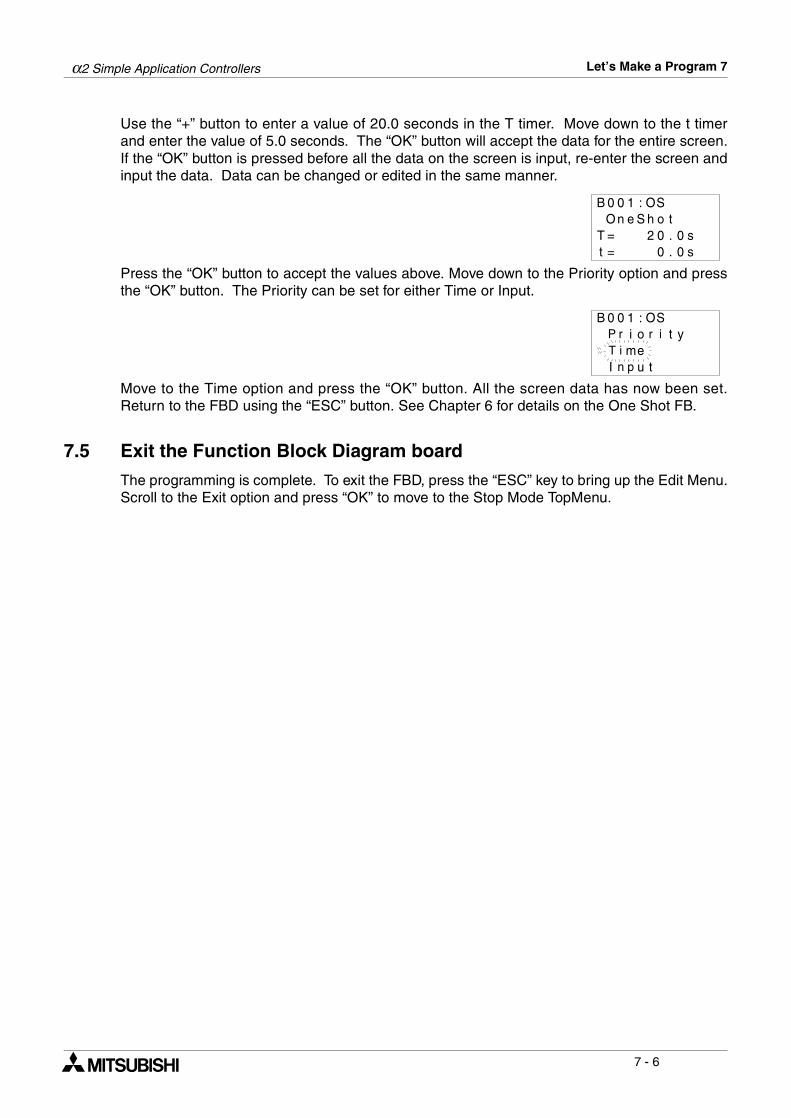
α2 Simple Application Controllers Let’s Make a Program 7
7 - 6
Use the “+” button to enter a value of 20.0 seconds in the T timer. Move down to the t timerand enter the value of 5.0 seconds. The “OK” button will accept the data for the entire screen.If the “OK” button is pressed before all the data on the screen is input, re-enter the screen andinput the data. Data can be changed or edited in the same manner.
Press the “OK” button to accept the values above. Move down to the Priority option and pressthe “OK” button. The Priority can be set for either Time or Input.
Move to the Time option and press the “OK” button. All the screen data has now been set.Return to the FBD using the “ESC” button. See Chapter 6 for details on the One Shot FB.
7.5 Exit the Function Block Diagram board
The programming is complete. To exit the FBD, press the “ESC” key to bring up the Edit Menu.Scroll to the Exit option and press “OK” to move to the Stop Mode TopMenu.
SO:10BtoSnO e
0T =h
0
s0.0t = s0.
2
SO:10Boir
0P ytir
emiTI tupn
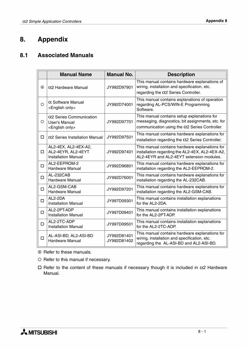
α2 Simple Application Controllers Appendix 8
8 - 1
8. Appendix
8.1 Associated Manuals
$ Refer to these manuals.
% Refer to this manual if necessary.
& Refer to the content of these manuals if necessary though it is included in α2 HardwareManual.
Manual Name Manual No. Description
$ α2 Hardware Manual JY992D97901This manual contains hardware explanations of wiring, installation and specification, etc. regarding the α2 Series Controller.
% α Software Manual<English only>
JY992D74001This manual contains explanations of operation regarding AL-PCS/WIN-E Programming Software.
%α2 Series Communication User’s Manual<English only>
JY992D97701This manual contains setup explanations for messaging, diagnostics, bit assignments, etc. for communication using the α2 Series Controller.
& α2 Series Installation Manual JY992D97501This manual contains hardware explanations for installation regarding the α2 Series Controller.
&AL2-4EX, AL2-4EX-A2, AL2-4EYR, AL2-4EYT Installation Manual
JY992D97401This manual contains hardware explanations for installation regarding the AL2-4EX, AL2-4EX-A2, AL2-4EYR and AL2-4EYT extension modules.
&AL2-EEPROM-2Hardware Manual
JY992D96801This manual contains hardware explanations for installation regarding the AL2-EEPROM-2.
&AL-232CABHardware Manual
JY992D76001This manual contains hardware explanations for installation regarding the AL-232CAB.
&AL2-GSM-CABHardware Manual
JY992D97201This manual contains hardware explanations for installation regarding the AL2-GSM-CAB.
&AL2-2DA Installation Manual
JY997D09301This manual contains installation explanations for the AL2-2DA.
&AL2-2PT-ADPInstallation Manual
JY997D09401This manual contains installation explanations for the AL2-2PT-ADP.
&AL2-2TC-ADPInstallation Manual
JY997D09501This manual contains installation explanations for the AL2-2TC-ADP.
&AL-ASI-BD, AL2-ASI-BDHardware Manual
JY992D81401JY992D81402
This manual contains hardware explanations for wiring, installation and specification, etc. regarding the AL-ASI-BD and AL2-ASI-BD.
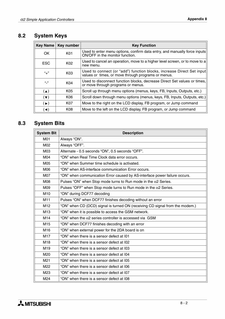
α2 Simple Application Controllers Appendix 8
8 - 2
8.2 System Keys
8.3 System Bits
Key Name Key number Key Function
OK K01 Used to enter menu options, confirm data entry, and manually force inputsON/OFF in the monitor function.
ESC K02 Used to cancel an operation, move to a higher level screen, or to move to anew menu.
“+” K03 Used to connect (or “add”) function blocks, increase Direct Set inputvalues or times, or move through programs or menus.
“-” K04 Used to disconnect function blocks, decrease Direct Set values or times,or move through programs or menus.
( ) K05 Scroll up through menu options (menus, keys, FB, Inputs, Outputs, etc.)
( ) K06 Scroll down through menu options (menus, keys, FB, Inputs, Outputs, etc.)
( ) K07 Move to the right on the LCD display, FB program, or Jump command
( ) K08 Move to the left on the LCD display, FB program, or Jump command
System Bit Description
M01 Always “ON”.
M02 Always “OFF”.
M03 Alternate - 0.5 seconds “ON”, 0.5 seconds “OFF”.
M04 “ON” when Real Time Clock data error occurs.
M05 “ON” when Summer time schedule is activated.
M06 “ON” when AS-interface communication Error occurs.
M07 “ON” when communication Error caused by AS-interface power failure occurs.
M08 Pulses “ON” when Stop mode turns to Run mode in the α2 Series.
M09 Pulses “OFF” when Stop mode turns to Run mode in the α2 Series.
M10 “ON” during DCF77 decoding
M11 Pulses “ON” when DCF77 finishes decoding without an error
M12 “ON” when CD (DCD) signal is turned ON (receiving CD signal from the modem.)
M13 “ON” when it is possible to access the GSM network.
M14 “ON” when the α2 series controller is accessed via GSM
M15 “ON” when DCF77 finishes decoding with an error
M16 “ON” when external power for the 2DA board is on
M17 “ON” when there is a sensor defect at I01
M18 “ON” when there is a sensor defect at I02
M19 “ON” when there is a sensor defect at I03
M20 “ON” when there is a sensor defect at I04
M21 “ON” when there is a sensor defect at I05
M22 “ON” when there is a sensor defect at I06
M23 “ON” when there is a sensor defect at I07
M24 “ON” when there is a sensor defect at I08
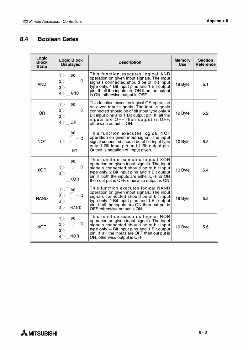
α2 Simple Application Controllers Appendix 8
8 - 3
8.4 Boolean Gates
Logic Block State
Logic Block Displayed Description Memory
UseSection
Reference
AND
This func t ion executes logical ANDoperation on given input signals. The inputsignals connected should be of bit inputtype only. 4 Bit input pins and 1 Bit outputpin. If all the inputs are ON then the outputis ON, otherwise output is OFF.
19 Byte 5.1
OR
This function executes logical OR operationon given input signals. The input signalsconnected should be of bit input type only. 4Bit input pins and 1 Bit output pin. If all theinputs are OFF then output i s OFF,otherwise output is ON.
19 Byte 5.2
NOT
This func t ion executes log ica l NOToperation on given input signal. The inputsignal connected should be of bit input typeonly. 1 Bit input pin and 1 Bit output pin.Output is negation of Input given.
10 Byte 5.3
XOR
This func t ion executes log ical XORoperation on given input signals. The inputsignals connected should be of bit inputtype only. 2 Bit input pins and 1 Bit outputpin.If both the inputs are either OFF or ONthen out put is OFF, otherwise output is ON
13 Byte 5.4
NAND
This function executes logical NANDoperation on given input signals. The inputsignals connected should be of bit inputtype only. 4 Bit input pins and 1 Bit outputpin. If all the inputs are ON then out put isOFF, otherwise output is ON
19 Byte 5.5
NOR
This func t ion executes logical NORoperation on given input signals. The inputsignals connected should be of bit inputtype only. 4 Bit input pins and 1 Bit outputpin. If all the inputs are OFF then out put isON, otherwise output is OFF
19 Byte 5.6
00
A N D
2
3
O
4
1
00
O R
2
3
O
4
1
00
N T
1O
00
XO R
1
2
O
00
N A N D
2
3
O
4
1
00
N O R
2
3
O
4
1
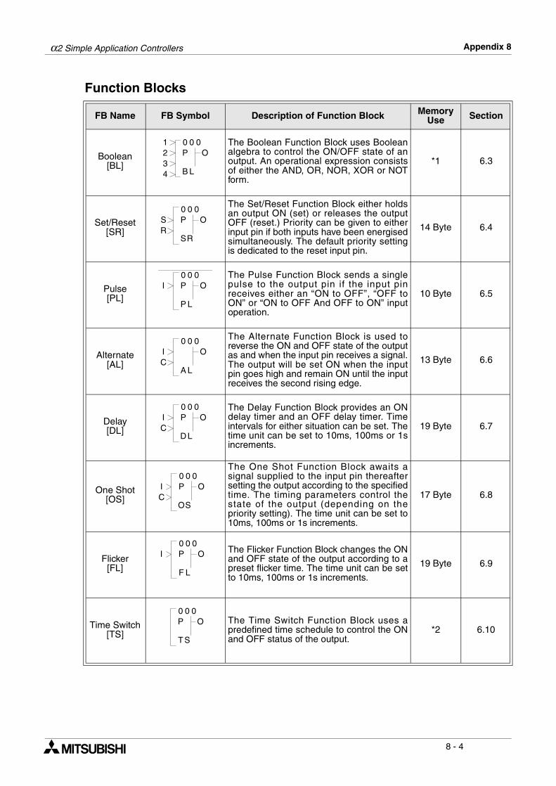
α2 Simple Application Controllers Appendix 8
8 - 4
Function Blocks
FB Name FB Symbol Description of Function Block Memory Use Section
Boolean[BL]
The Boolean Function Block uses Booleanalgebra to control the ON/OFF state of anoutput. An operational expression consistsof either the AND, OR, NOR, XOR or NOTform.
*1 6.3
Set/Reset[SR]
The Set/Reset Function Block either holdsan output ON (set) or releases the outputOFF (reset.) Priority can be given to eitherinput pin if both inputs have been energisedsimultaneously. The default priority settingis dedicated to the reset input pin.
14 Byte 6.4
Pulse[PL]
The Pulse Function Block sends a singlepulse to the output pin if the input pinreceives either an “ON to OFF”, “OFF toON” or “ON to OFF And OFF to ON” inputoperation.
10 Byte 6.5
Alternate[AL]
The Alternate Function Block is used toreverse the ON and OFF state of the outputas and when the input pin receives a signal.The output will be set ON when the inputpin goes high and remain ON until the inputreceives the second rising edge.
13 Byte 6.6
Delay[DL]
The Delay Function Block provides an ONdelay timer and an OFF delay timer. Timeintervals for either situation can be set. Thetime unit can be set to 10ms, 100ms or 1sincrements.
19 Byte 6.7
One Shot[OS]
The One Shot Function Block awaits asignal supplied to the input pin thereaftersetting the output according to the specifiedtime. The timing parameters control thestate of the output (depending on thepriority setting). The time unit can be set to10ms, 100ms or 1s increments.
17 Byte 6.8
Flicker[FL]
The Flicker Function Block changes the ONand OFF state of the output according to apreset flicker time. The time unit can be setto 10ms, 100ms or 1s increments.
19 Byte 6.9
Time Switch[TS]
The Time Switch Function Block uses apredefined time schedule to control the ONand OFF status of the output.
*2 6.10
0 001
LB
O234
P
0 00
RS
OSR
P
0 00
LP
OI P
0 00
LA
OIC
0 00
LD
OIC
P
0 00
SO
OIC
P
0 00
LF
OI P
0 00
ST
OP
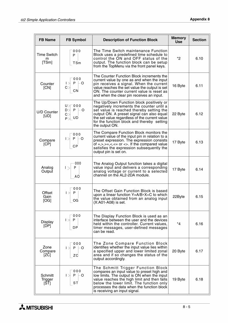
α2 Simple Application Controllers Appendix 8
8 - 5
Time Switch m
[TSm]
The Time Switch maintenance FunctionBlock uses a predefined time schedule tocontrol the ON and OFF status of theoutput. The function block can be setupfrom the TopMenu via the front panel keys.
*2 6.10
Counter[CN]
The Counter Function Block increments thecurrent value by one as and when the inputpin receives a signal. When the currentvalue reaches the set value the output is setON. The counter current value is reset asand when the clear pin receives an input.
16 Byte 6.11
U/D Counter[UD]
The Up/Down Function block positively ornegatively increments the counter until aset value is reached thereby setting theoutput ON. A preset signal can also equalthe set value regardless of the current valuefor the function block and thereby settingthe output ON.
22 Byte 6.12
Compare[CP]
The Compare Function Block monitors thecurrent value of the input pin in relation to apreset expression. The expression consistsof =,>,>=,<,<= or <>. If the compared valuesatisfies the expression subsequently theoutput pin is set on.
17 Byte 6.13
Analog Output
The Analog Output function takes a digitalvalue input and delivers a correspondinganalog voltage or current to a selectedchannel on the AL2-2DA module.
17 Byte 6.14
Offset Gain[OG]
The Offset Gain Function Block is basedupon a linear function Y=A/B∗X+C to whichthe value obtained from an analog input(X:A01-A08) is set.
22Byte 6.15
Display[DP]
The Display Function Block is used as aninterface between the user and the devicesheld within the controller. Current values,timer messages, user-defined messagescan be read.
*4 6.16
Zone Compare
[ZC]
The Zone Compare Funct ion B lockidentifies whether the input value lies withina specified upper and lower limited zonalarea and if so changes the status of theoutput accordingly.
20 Byte 6.17
Schmitt Trigger
[ST]
The Schmit t Tr igger Funct ion Blockcompares an input value to preset high andlow limits. The output is ON when the inputvalue reaches the high limit and then fallsbelow the lower limit. The function onlyprocesses the data when the function blockis receiving an input signal.
19 Byte 6.18
FB Name FB Symbol Description of Function Block Memory Use Section
0 00
ST m
P
0 00
NC
OIC
P
0 00U
DU
ODCP
P
0 00
PC
OI P
000
A O
I P
0 00
GO
I P
0 00
PD
I P
0 00
CZ
OI P
0 00
TS
OI P
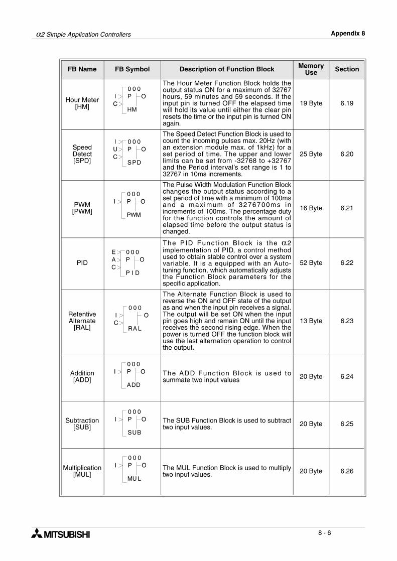
α2 Simple Application Controllers Appendix 8
8 - 6
Hour Meter[HM]
The Hour Meter Function Block holds theoutput status ON for a maximum of 32767hours, 59 minutes and 59 seconds. If theinput pin is turned OFF the elapsed timewill hold its value until either the clear pinresets the time or the input pin is turned ONagain.
19 Byte 6.19
Speed Detect[SPD]
The Speed Detect Function Block is used tocount the incoming pulses max. 20Hz (withan extension module max. of 1kHz) for aset period of time. The upper and lowerlimits can be set from -32768 to +32767and the Period interval’s set range is 1 to32767 in 10ms increments.
25 Byte 6.20
PWM[PWM]
The Pulse Width Modulation Function Blockchanges the output status according to aset period of time with a minimum of 100msand a max imum o f 3276700ms inincrements of 100ms. The percentage dutyfor the function controls the amount ofelapsed time before the output status ischanged.
16 Byte 6.21
PID
The P ID Func t ion B lock i s the α2implementation of PID, a control methodused to obtain stable control over a systemvariable. It is a equipped with an Auto-tuning function, which automatically adjuststhe Function Block parameters for thespecific application.
52 Byte 6.22
Retentive Alternate
[RAL]
The Alternate Function Block is used toreverse the ON and OFF state of the outputas and when the input pin receives a signal.The output will be set ON when the inputpin goes high and remain ON until the inputreceives the second rising edge. When thepower is turned OFF the function block willuse the last alternation operation to controlthe output.
13 Byte 6.23
Addition[ADD]
The ADD Funct ion B lock is used tosummate two input values 20 Byte 6.24
Subtraction[SUB]
The SUB Function Block is used to subtracttwo input values. 20 Byte 6.25
Multiplication[MUL]
The MUL Function Block is used to multiplytwo input values. 20 Byte 6.26
FB Name FB Symbol Description of Function Block Memory Use Section
0 00
MH
OIC
P
0 00
PS
OUC
I
D
P
0 00
WP
OI
M
P
0 00
IP
OA
D
PE
C
0 00
LA
OIC
R
0 00
DA
OI
D
P
0 00
US
OI
B
P
0 00
UM
OI
L
P
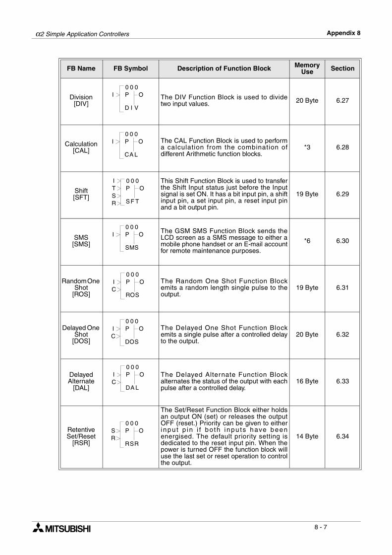
α2 Simple Application Controllers Appendix 8
8 - 7
Division[DIV]
The DIV Function Block is used to dividetwo input values. 20 Byte 6.27
Calculation[CAL]
The CAL Function Block is used to performa calculation from the combination ofdifferent Arithmetic function blocks.
*3 6.28
Shift[SFT]
This Shift Function Block is used to transferthe Shift Input status just before the Inputsignal is set ON. It has a bit input pin, a shiftinput pin, a set input pin, a reset input pinand a bit output pin.
19 Byte 6.29
SMS[SMS]
The GSM SMS Function Block sends theLCD screen as a SMS message to either amobile phone handset or an E-mail accountfor remote maintenance purposes.
*6 6.30
Random One Shot
[ROS]
The Random One Shot Function Blockemits a random length single pulse to theoutput.
19 Byte 6.31
Delayed One Shot
[DOS]
The Delayed One Shot Function Blockemits a single pulse after a controlled delayto the output.
20 Byte 6.32
Delayed Alternate
[DAL]
The Delayed Alternate Function Blockalternates the status of the output with eachpulse after a controlled delay.
16 Byte 6.33
Retentive Set/Reset
[RSR]
The Set/Reset Function Block either holdsan output ON (set) or releases the outputOFF (reset.) Priority can be given to eitherinpu t p in i f bo th i npu ts have beenenergised. The default priority setting isdedicated to the reset input pin. When thepower is turned OFF the function block willuse the last set or reset operation to controlthe output.
14 Byte 6.34
FB Name FB Symbol Description of Function Block Memory Use Section
0 00
ID
OI
V
P
0 00
AC
OI
L
P
0 00I
TS
OTSR F
P
0 00
MS
OI
S
P
0 00
OR
OI
SC
P
0 00
OD
OI
SC
P
0 00
AD
OI
LC
P
0 00
SR
OSR
R
P
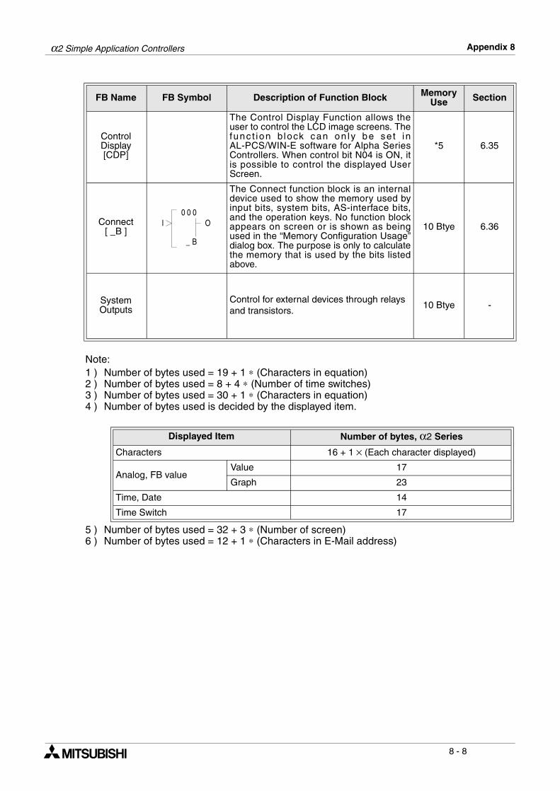
α2 Simple Application Controllers Appendix 8
8 - 8
Note:1 ) Number of bytes used = 19 + 1 ∗ (Characters in equation)2 ) Number of bytes used = 8 + 4 ∗ (Number of time switches)3 ) Number of bytes used = 30 + 1 ∗ (Characters in equation)4 ) Number of bytes used is decided by the displayed item.
5 ) Number of bytes used = 32 + 3 ∗ (Number of screen)6 ) Number of bytes used = 12 + 1 ∗ (Characters in E-Mail address)
Control Display[CDP]
The Control Display Function allows theuser to control the LCD image screens. Thefunc t ion b lock can on ly be se t i nAL-PCS/WIN-E software for Alpha SeriesControllers. When control bit N04 is ON, itis possible to control the displayed UserScreen.
*5 6.35
Connect[ _B ]
The Connect function block is an internaldevice used to show the memory used byinput bits, system bits, AS-interface bits,and the operation keys. No function blockappears on screen or is shown as beingused in the “Memory Configuration Usage”dialog box. The purpose is only to calculatethe memory that is used by the bits listedabove.
10 Btye 6.36
System Outputs
Control for external devices through relays and transistors.
10 Btye -
Displayed Item Number of bytes, α2 Series
Characters 16 + 1 × (Each character displayed)
Analog, FB valueValue 17
Graph 23
Time, Date 14
Time Switch 17
FB Name FB Symbol Description of Function Block Memory Use Section
00
B_
OI0
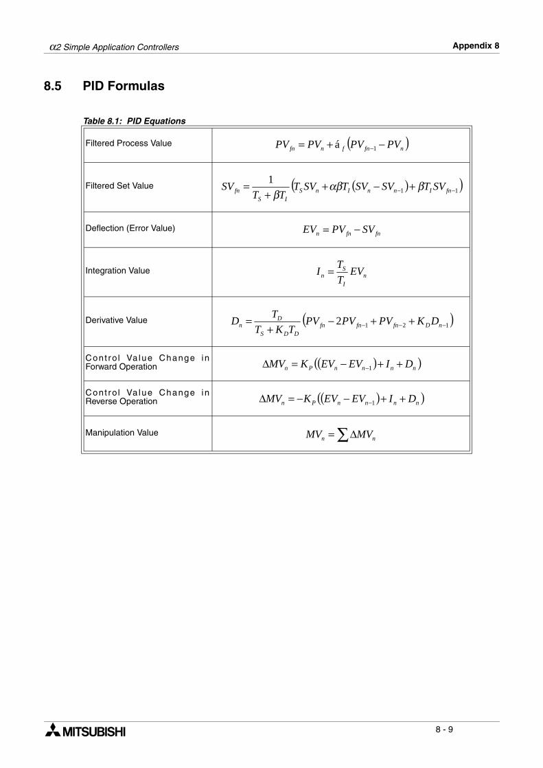
α2 Simple Application Controllers Appendix 8
8 - 9
8.5 PID Formulas
Table 8.1: PID Equations
Filtered Process Value
Filtered Set Value
Deflection (Error Value)
Integration Value
Derivative Value
Cont ro l Va lue Change inForward Operation
Cont ro l Va lue Change inReverse Operation
Manipulation Value
( )nfnfnfn PVPVPVPV −+= −1á
( )( )11
1−− +−+
+= fnInnInS
ISfn SVTSVSVTSVT
TTSV βαβ
β
fnfnn SVPVEV −=
nI
Sn EV
T
TI =
( )1212 −−− ++−+
= nDfnfnfnDDS
Dn DKPVPVPV
TKT
TD
( )( )nnnnPn DIEVEVKMV ++−=∆ −1
( )( )nnnnPn DIEVEVKMV ++−−=∆ −1
∑∆= nn MVMV
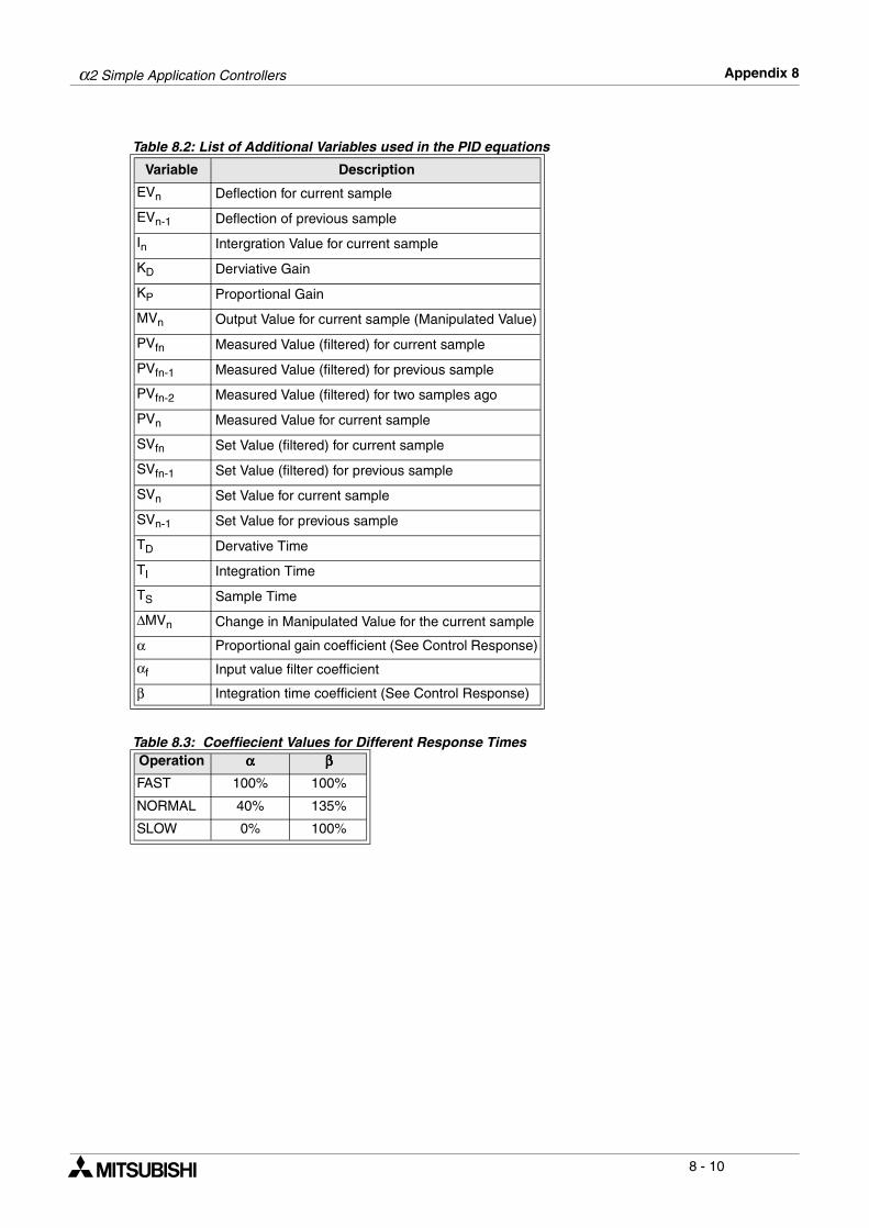
α2 Simple Application Controllers Appendix 8
8 - 10
Table 8.2: List of Additional Variables used in the PID equations
Variable Description
EVn Deflection for current sample
EVn-1 Deflection of previous sample
In Intergration Value for current sample
KD Derviative Gain
KP Proportional Gain
MVn Output Value for current sample (Manipulated Value)
PVfn Measured Value (filtered) for current sample
PVfn-1 Measured Value (filtered) for previous sample
PVfn-2 Measured Value (filtered) for two samples ago
PVn Measured Value for current sample
SVfn Set Value (filtered) for current sample
SVfn-1 Set Value (filtered) for previous sample
SVn Set Value for current sample
SVn-1 Set Value for previous sample
TD Dervative Time
TI Integration Time
TS Sample Time
∆MVn Change in Manipulated Value for the current sample
α Proportional gain coefficient (See Control Response)
αf Input value filter coefficient
β Integration time coefficient (See Control Response)
Table 8.3: Coeffiecient Values for Different Response TimesOperation αααα ββββ
FAST 100% 100%
NORMAL 40% 135%
SLOW 0% 100%
α2 Simple Application Controllers
• Under no circumstances will Mitsubishi Electric be liable responsible for any consequentialdamage that may arise as a result of the installation or use of this equipment.
• All examples and diagrams shown in this manual are intended only as an aid to understanding thetext, not to guarantee operation. Mitsubishi Electric will accept no responsibility for actual use ofthe product based on these illustrative examples.
• Please contact a Mitsubishi Electric distributor for more information concerning applications in lifecritical situations or high reliability.

HEAD OFFICE: MITSUBISHI DENKI BLDG MARUNOUCHI TOKYO 100-8310HIMEJI WORKS: 840, CHIYODA CHO, HIMEJI, JAPAN
JY992D97101B(MEE)
Effective Oct. 2003Specifications are subject to change without notice.