Embed Size (px)
Citation preview
AL-1809 / ATS1809 Universal Interface Installation and Programming Guide
P/N 1070740 (EN) • REV C • ISS 09JUL13
Copyright © 2013 UTC Fire & Security Americas Corporation, Inc. All rights
reserved.
Trademarks and
patents
Interlogix, the AL-1809 / ATS1809 Universal Interface name and logo
are trademarks of UTC Fire & Security.
Other trade names used in this document may be trademarks or
registered trademarks of the manufacturers or vendors of the
respective products.
Manufacturer UTC Fire & Security Americas Corporation, Inc.
1275 Red Fox Rd., Arden Hills, MN 55112-6943, USA
Authorized EU manufacturing representative:
UTC Fire & Security B.V.
Kelvinstraat 7, 6003 DH Weert, Netherlands
FCC compliance This device complies with part 15 of the FCC Rules. Operation is
subject to the following two conditions: (1) This device may not
cause harmful interference, and (2) this device must accept any
interference received, including interference that may cause
undesired operation.
Certification
EN 50136 Tested against and compliant with: EN 50136-1-1, EN 50136-2-1
Performance criteria: ATS5 (D3, M3, T4, S2, I3)
The ATS1809 works in pass-through operation. The
acknowledgement signal as received by the Universal Interface from
the OH Network Receiver is forwarded to the panel within
requirements of the ATS class specified above.
Tested and certified by Telefication B.V.
European Union
directives
1999/5/EC (R&TTE directive): Hereby, UTC Fire & Security
declares that this device is in compliance with the essential
requirements and other relevant provisions of Directive 1999/5/EC.
2002/96/EC (WEEE directive): Products marked with this symbol
cannot be disposed of as unsorted municipal waste in the European
Union. For proper recycling, return this product to your local supplier
upon the purchase of equivalent new equipment, or dispose of it at
designated collection points. For more information see:
www.recyclethis.info.
Contact information www.utcfireandsecurity.com or www.interlogix.com
Customer support www.utcfssecurityproducts.eu
AL-1809 / ATS1809 Universal Interface Installation and Programming Guide i
Content
Introduction 1
Main features 2
Web interface 3
Installer and cabling requirements 3
Products overview 3
Installation 5
Overview 5
Setting up the control panel 5
Setting up the installation computer 5
Installing the Universal Interface 6
Programming 9
Logging in 10
User name and password 10
Network settings 10
Control panel options 12
Firewall rules 13
Email/TFTP parameters 14
Network Receiver parameters 15
Message format 16
Finishing the installation 17
Reference section 18
Additional programming 18
RAS keystrokes to program the computer address 19
RAS keystrokes to program the security password 19
RAS keystrokes to program central station parameters 19
Using the default jumper 20
LED indication 21
Universal Interface utilities 21
Sample network diagram 22
Specifications 24
Software 24
Network primitive frame size (bytes) 24
Hardware 24
Installation worksheet 25

AL-1809 / ATS1809 Universal Interface Installation and Programming Guide 1
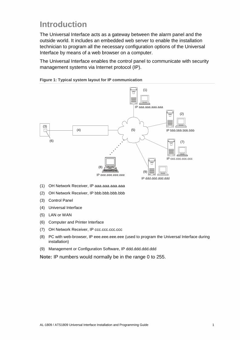
Introduction The Universal Interface acts as a gateway between the alarm panel and the
outside world. It includes an embedded web server to enable the installation
technician to program all the necessary configuration options of the Universal
Interface by means of a web browser on a computer.
The Universal Interface enables the control panel to communicate with security
management systems via Internet protocol (IP).
Figure 1: Typical system layout for IP communication
(1) OH Network Receiver, IP aaa.aaa.aaa.aaa
(2) OH Network Receiver, IP bbb.bbb.bbb.bbb
(3) Control Panel
(4) Universal Interface
(5) LAN or WAN
(6) Computer and Printer Interface
(7) OH Network Receiver, IP ccc.ccc.ccc.ccc
(8) PC with web-browser, IP eee.eee.eee.eee (used to program the Universal Interface during
installation)
(9) Management or Configuration Software, IP ddd.ddd.ddd.ddd
Note: IP numbers would normally be in the range 0 to 255.
(1)
(2)
(3)(4) (5)
(6) (7)
(8)
(9)
IP aaa.aaa.aaa.aaa
IP bbb.bbb.bbb.bbb
I ccc.ccc.ccc.cccP
I ddd.ddd.ddd.dddP I eee.eee.eee.eeeP
2 AL-1809 / ATS1809 Universal Interface Installation and Programming Guide
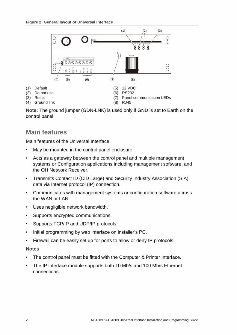
Figure 2: General layout of Universal Interface
(1) Default
(2) Do not use
(3) Reset
(4) Ground link
(5) 12 VDC
(6) RS232
(7) Panel communication LEDs
(8) RJ45
Note: The ground jumper (GDN-LNK) is used only if GND is set to Earth on the
control panel.
Main features
Main features of the Universal Interface:
• May be mounted in the control panel enclosure.
• Acts as a gateway between the control panel and multiple management
systems or Configuration applications including management software, and
the OH Network Receiver.
• Transmits Contact ID (CID Large) and Security Industry Association (SIA)
data via Internet protocol (IP) connection.
• Communicates with management systems or configuration software across
the WAN or LAN.
• Uses negligible network bandwidth.
• Supports encrypted communications.
• Supports TCP/IP and UDP/IP protocols.
• Initial programming by web interface on installer’s PC.
• Firewall can be easily set up for ports to allow or deny IP protocols.
Notes
• The control panel must be fitted with the Computer & Printer Interface.
• The IP interface module supports both 10 Mb/s and 100 Mb/s Ethernet
connections.
+1
2V
GN
D
EA
RT
H
CT
S
RT
S
RX
IN
TX
OU
T
GN
D
Tx1
Rx1
GND-LNK
DEF CON10 CON11 RST
CON4
CON3
CON1
(1) (2) (3)
(4) (5) (6) (7) (8)
AL-1809 / ATS1809 Universal Interface Installation and Programming Guide 3
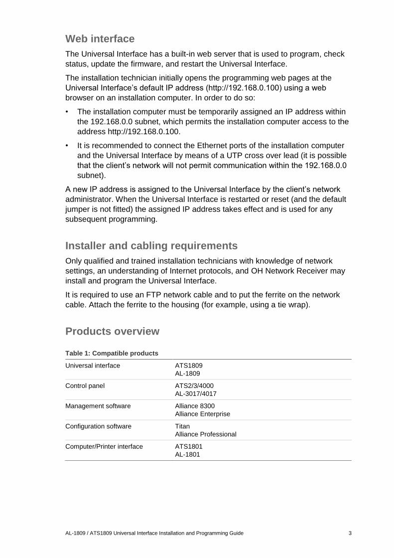
Web interface
The Universal Interface has a built-in web server that is used to program, check
status, update the firmware, and restart the Universal Interface.
The installation technician initially opens the programming web pages at the
Universal Interface’s default IP address (http://192.168.0.100) using a web
browser on an installation computer. In order to do so:
• The installation computer must be temporarily assigned an IP address within
the 192.168.0.0 subnet, which permits the installation computer access to the
address http://192.168.0.100.
• It is recommended to connect the Ethernet ports of the installation computer
and the Universal Interface by means of a UTP cross over lead (it is possible
that the client’s network will not permit communication within the 192.168.0.0
subnet).
A new IP address is assigned to the Universal Interface by the client’s network
administrator. When the Universal Interface is restarted or reset (and the default
jumper is not fitted) the assigned IP address takes effect and is used for any
subsequent programming.
Installer and cabling requirements
Only qualified and trained installation technicians with knowledge of network
settings, an understanding of Internet protocols, and OH Network Receiver may
install and program the Universal Interface.
It is required to use an FTP network cable and to put the ferrite on the network
cable. Attach the ferrite to the housing (for example, using a tie wrap).
Products overview
Table 1: Compatible products
Universal interface ATS1809
AL-1809
Control panel ATS2/3/4000
AL-3017/4017
Management software Alliance 8300
Alliance Enterprise
Configuration software Titan
Alliance Professional
Computer/Printer interface ATS1801
AL-1801
4 AL-1809 / ATS1809 Universal Interface Installation and Programming Guide
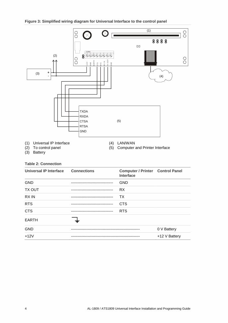
Figure 3: Simplified wiring diagram for Universal Interface to the control panel
(1) Universal IP Interface
(2) To control panel
(3) Battery
(4) LAN/WAN
(5) Computer and Printer Interface
Table 2: Connection
Universal IP Interface Connections Computer / Printer
Interface
Control Panel
GND --------------------------------- GND
TX OUT --------------------------------- RX
RX IN --------------------------------- TX
RTS --------------------------------- CTS
CTS --------------------------------- RTS
EARTH
GND ------------------------------------------------------ 0 V Battery
+12V ------------------------------------------------------ +12 V Battery
+1
2V
GN
D
EA
RT
H
CT
S
RT
S
RX
IN
TX
OU
T
GN
D
CON4
(1)
(2)
(3)(4)
(5)
AL-1809 / ATS1809 Universal Interface Installation and Programming Guide 5
Installation
Overview
In order for you to install and program a Universal Interface, you must first:
• Use an LCD RAS on the control panel’s LAN to obtain (or program) the
panel’s computer address and security password, and to program central
station reporting (if required). See “Setting up the control panel” below.
• Set up the installation computer on which you will use a web browser to
program the Universal Interface’s configuration options. See “Setting up the
installation computer” below.
• Obtain a number of details about the installation from various sources. These
details are listed on a blank installation worksheet on page 25 that you can
copy for reuse.
The overall process of installing a Universal Interface consists of the following
tasks.
• Setting up the control panel described below
• Setting up the installation computer described below
• Installing the Universal Interface described on page 6
• Programming described on page 9
• Finishing the installation described on page 17
Setting up the control panel
The following control panel options must be programmed via Menu, 19, 29:
• Computer address
• Security password
• Central Station parameters
Refer to pages 13 and 19 for details.
Setting up the installation computer
The Universal Interface is programmed using a web browser to display the web
pages generated by the Universal Interface’s embedded web server at either the
default IP address or the assigned IP address (provided by the local network
administrator). In either case, you must configure the web browser to directly
display the Universal Interface’s web pages without using the network proxy
server.
Note: Seek advice from the client’s IT staff before you start.
The following example is for Internet Explorer 5. Use the correct procedure for
your particular web browser.
6 AL-1809 / ATS1809 Universal Interface Installation and Programming Guide
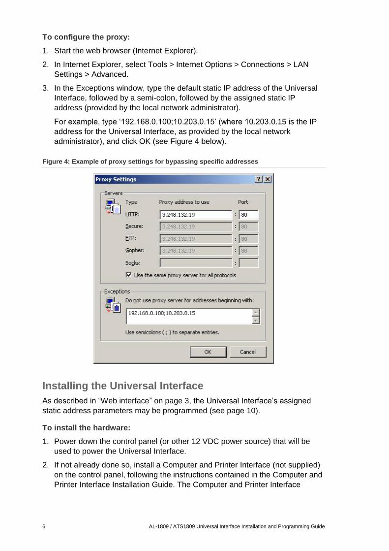
To configure the proxy:
1. Start the web browser (Internet Explorer).
2. In Internet Explorer, select Tools > Internet Options > Connections > LAN
Settings > Advanced.
3. In the Exceptions window, type the default static IP address of the Universal
Interface, followed by a semi-colon, followed by the assigned static IP
address (provided by the local network administrator).
For example, type ‘192.168.0.100;10.203.0.15’ (where 10.203.0.15 is the IP
address for the Universal Interface, as provided by the local network
administrator), and click OK (see Figure 4 below).
Figure 4: Example of proxy settings for bypassing specific addresses
Installing the Universal Interface
As described in “Web interface” on page 3, the Universal Interface’s assigned
static address parameters may be programmed (see page 10).
To install the hardware:
1. Power down the control panel (or other 12 VDC power source) that will be
used to power the Universal Interface.
2. If not already done so, install a Computer and Printer Interface (not supplied)
on the control panel, following the instructions contained in the Computer and
Printer Interface Installation Guide. The Computer and Printer Interface
AL-1809 / ATS1809 Universal Interface Installation and Programming Guide 7
provides an RS232 connection between the control panel and the Universal
Interface.
3. Mount the Universal Interface in the control panel enclosure. Use a fixed pillar
if possible, otherwise connect the lug to earth.
Note: The distance from the control panel to the Universal Interface must not
exceed 1 meter.
4. Connect the Computer & Printer Interface “Computer” port to the Universal
Interface, using the supplied plug-on screw terminals. See the simplified
wiring diagram in Figure 3 on page 4 for details.
5. Connect GND to Earth using jumper GDN-LNK. See Figure 2 on page 2 for
the location of GDN-LNK.
Note: This step applies only if GND is set to Earth on the control panel.
Configuration
This procedure may be used for all control panels and must be used in all cases
where the Universal Interface does not have the factory-default settings (e.g. a
previously-fitted unit).
Note: The installation computer must be temporarily assigned an IP address
within the 192.168.0.0 subnet, which permits the installation computer access to
the address http://192.168.0.100.
To configure the universal interface:
1. Change the installation computer’s IP address settings to be within the
192.168.0.0 subnet, i.e. 192.168.0.X, where X is any number from 1-254 (do
not use 192.168.0.100 as the Universal Interface uses this).
Record the installation computer’s original settings so that you can restore
them after programming the Universal Interface at the default address.
2. Fit the Universal Interface’s default jumper (DEF) to default the Universal
Interface to the factory settings. See “Using the default jumper” on page 20
for details.
3. Attach power cables between the Universal Interface, and battery wires and
the auxiliary power terminals on the control panel (or other 12 VDC power
source), using the taps from the accessory bag. See also Figure 3 on page 4.
4. Connect the Ethernet ports of the installation computer and the Universal
Interface by means of a UTP cross over lead. Alternatively, connect the
Internet/Ethernet cable from the Universal Interface to your network IP
connection point (however, it is possible that the client’s network will not
permit communication within the 192.168.0.0 subnet).
5. Re-power the control panel (or other 12 VDC power source) to power the
Universal Interface.
6. Go to “Programming” on page 9 to program the static address parameters
and all remaining options via the default IP address.
8 AL-1809 / ATS1809 Universal Interface Installation and Programming Guide
7. Follow the appropriate procedures in “Finishing the installation” on page 17 to
complete the installation.
AL-1809 / ATS1809 Universal Interface Installation and Programming Guide 9
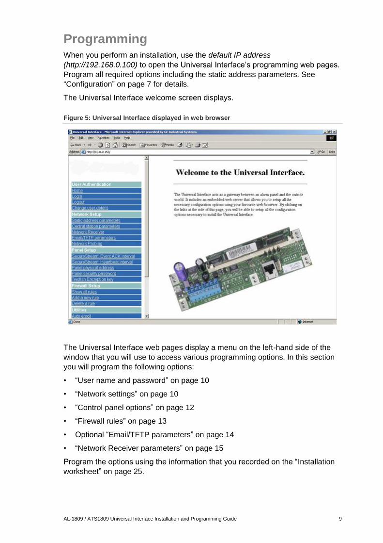
Programming When you perform an installation, use the default IP address
(http://192.168.0.100) to open the Universal Interface’s programming web pages.
Program all required options including the static address parameters. See
“Configuration” on page 7 for details.
The Universal Interface welcome screen displays.
Figure 5: Universal Interface displayed in web browser
The Universal Interface web pages display a menu on the left-hand side of the
window that you will use to access various programming options. In this section
you will program the following options:
• “User name and password” on page 10
• “Network settings” on page 10
• “Control panel options” on page 12
• “Firewall rules” on page 13
• Optional “Email/TFTP parameters” on page 14
• “Network Receiver parameters” on page 15
Program the options using the information that you recorded on the “Installation
worksheet” on page 25.
10 AL-1809 / ATS1809 Universal Interface Installation and Programming Guide
Logging in
Click Login in the User Authentication section of the Universal Interface menu to
display the login window. Use the default case sensitive user name
ADVISOR MASTER (ATS1809) or ALLIANCE MASTER (AL-1809), and
password 998765 to log in to the Universal Interface and begin a session.
It is important to note that:
• Login sessions automatically terminate after five minutes. If you need more
than 5 minutes to complete your work, logout and login again to begin a new
5-minute session.
• If an incorrect user name/password is entered more than five times, more
attempts to log in will be delayed by about 60 seconds. After about 60
seconds, logins are allowed as usual.
• When programming the Universal Interface, you must save your changes
using the Submit button on each page before you refresh the web browser or
logout, otherwise your changes will be lost.
• You may need to refresh the web browser in order to see the latest data from
the Universal Interface.
User name and password
Use the default user name and password to initially log in to the Universal
Interface and begin a session. Click Change User Details in the User
Authentication section of the Universal Interface menu to program the required
user name and password.
Network settings
To set up the network:
1. Click Static Address Parameters in the Network Setup section of the
Universal Interface menu to display the network parameters setup window.
Type the new IP address, net mask and gateway address (provided by the
local network administrator) for the Universal Interface and click Submit.
2. The Universal Interface should be configured to communicate with central
station reporting and/or management software.
Click Central Station Parameters in the Network Setup section of the
Universal Interface menu and type the IP addresses for any CID site or
management software site collecting control panel events via IP. Three
entries are available for reporting to a OH Network Receiver (listed under
Alarm Reporting Central Station), and twelve are available for communication
to management applications (listed as entry 4 – 15 under Management
Central Stations):
• Alarm Reporting Central Station 1 is the main OH Network Receiver
AL-1809 / ATS1809 Universal Interface Installation and Programming Guide 11
• Alarm Reporting Central Station 2 is the backup OH Network Receiver
• Alarm Reporting Central Station 3 is the disaster OH Network Receiver
• Management Central Station 4 to 15 are intended for connection to
management software
For each IP address, select the options for Protocol, Port, Event type, and
Encryption. See Figure 6 on page 12 for details, and Table 3 below for
allowable settings. Click Submit.
3. Network probing is an additional feature that will send a message using TCP
port 22222 to all programmed IP addresses in Central Station parameters.
The first to return an answer will prevent the Universal Interface from
generating a Line fault with Universal E-Link error. When enabled, firewall
rules should be setup such that they do not block this message (this includes
the Windows XP firewall). At least one PC in the programmed list should
remain active.
When disabled, no network probing is performed. Normal polling mechanisms
however remain in operation.
This test is performed every 12 seconds.
Note: When finished programming the Universal Interface, click Restart
Communications in the Utilities section of the main menu to update the system
data.
Table 3: Allowable central station parameters
Allowable settings OH Network Receiver Management / Configuration Software
Protocol TCP UDP
Event type CID, SIA, or XSIA Computer event only
Encryption Triple DES Twofish or none
12 AL-1809 / ATS1809 Universal Interface Installation and Programming Guide
Figure 6: Setting up Central Station Parameters
(1) OH Network Receiver
(2) Main
(3) Backup
(4) Disaster
(5) Management/Configuration Software
Control panel options
This section covers how to program the following control panel options:
• Panel Physical (Computer) Address*
• Panel Security Password*
• Twofish Encryption Key
* Must always match details keyed at the RAS keypad.
To set the panel options:
1. Click Panel Physical Address in the Panel Setup section of the Universal
Interface menu. Type the correct computer address (Installer menu 19–29 in
the control panel) and click Submit. The value may not be 0.
2. Click Panel Security Password in the Panel Setup section of the Universal
Interface menu. Type the 10-digit password and click Submit.
AL-1809 / ATS1809 Universal Interface Installation and Programming Guide 13
This password must match the security password that was keyed in the
control panel at menu 19–29 during installation.
Tip: As a precaution, delete any temporary files your browser creates each
time the security password is submitted.
Tip: The security password can also be changed using management or
configuration software once connection is established.
3. Click Twofish Encryption Key in the Panel Setup section of the Universal
Interface menu. Typing in all zeros disables encryption, even if enable is
selected. Accepts up to 16 numbers, each three-digit number in each field
can be from 0 to 255. Keep a record of your encryption key. Click Enable and
Submit.
Notes
• It is highly recommended to set the Two-fish encryption key
• The same key needs to be setup in the ATS8000/ATS8300 Titan/Alliance
software
• As a precaution, delete any temporary files your browser creates each
time encryption is submitted
Note: When finished programming the Universal Interface, click Restart
Communications in the Utilities section of the main menu to update the system
data.
Firewall rules
Firewall rules allow you to accept or deny one or more selected communication
protocols and associated data.
Adding a new rule to accept a protocol doesn’t stop communication with other
protocols. To deny a protocol you need to either set up a specific rule, or use the
option Set default rule to deny all connections.
The Show all rules and Delete a Rule functions are self-explanatory and are not
explained here.
The system diagram depicted in Figure 7 on page 22 shows several system
components (OH Network Receiver, Management/Configuration Software, and a
computer with a web browser). Table 7 on page 23 summarizes the firewall rules
for the sample system.
To configure the firewall:
1. Add a rule so that the computer with the web browser can access the
Universal Interface.
Click Add a new rule in the Firewall Setup section of the Universal Interface
menu. Type the IP address of the computer with the web browser, type port
number 80, select TCP, select Accept, and click Submit.
Note: Setting the port number to 0 (zero), allows all port numbers.
14 AL-1809 / ATS1809 Universal Interface Installation and Programming Guide
Repeat this step for any other computers requiring web access to the
Universal Interface.
2. Add a rule for each CID station or management/configuration software station
that requires access via the Universal Interface.
Click Add a new rule in the Firewall Setup section of the Universal Interface
menu. Type the IP address of the CID station or management software
station, type port number 3001, select UDP, select Accept, and click Submit.
Note: Setting the port number to 0 (zero), allows all port numbers.
Repeat this step for each CID station or management/configuration software
station that requires access via the Universal Interface.
3. Add a rule to enable a ping test, if required.
Click Add a new rule in the Firewall Setup section of the Universal Interface
menu. Type the IP address of the computer from which you want to perform a
ping test, select ICMP, select Accept, and click Submit.
We recommend that ICMP is normally disabled, and only used temporarily for
testing.
4. Click Set default rule to deny all connections in the Firewall Setup section of
the Universal Interface menu to exclude any other connections than the ones
that you created rules for, and click Submit.
Notes
• The Universal Interface uses a mechanism (Network Probing) where it can
transmit a message using TCP port 22222 to check if a network is present (if
enabled, see Network Setup > Network Probing). It will try to send this
message to every central station programmed. The first to return an answer
(Acknowledge or Reject) will stop further testing until the next test (12 second
intervals).
• The usage of the firewall is recommended for maximum system security.
Consult your IT department as routers and other (hardware) firewalls are
managed and updated by them.
• In case one gets locked out due to a configuration error, use the default
jumper (see “Using the default jumper” on page 20) to get access again.
• If the PC at the receiving end has a firewall running (like Windows XP firewall)
this also requires to be configured such that the ports are opened.
Email/TFTP parameters
This functionality is not supported.
AL-1809 / ATS1809 Universal Interface Installation and Programming Guide 15
Network Receiver parameters
To set up the receiver parameters:
1. Click Network Receiver in the Network Setup section of the Universal
Interface menu.
2. Type the Receiver number.
A monitoring station normally has multiple network receivers passing
information to it, identified by the receiver number. Up to three digits are valid,
from 0 to 255. Obtain this number from the monitoring/central station.
If desired the Central Station can override this value in the Network Receiver.
3. Type the Line number.
This number identifies which line card delivered the error message from the
panel. Up to three digits are valid, from 0 to 255. Obtain this number from the
monitoring/central station.
If desired the Central Station can override this value in the Network Receiver.
4. Type the Heartbeat interval.
The heartbeat interval defines the interval between heartbeats in seconds.
0 to 255 seconds are valid.
In order to be able to detect line faults, the heartbeat interval must be greater
than 0.
Note: The heartbeats in this case are sent by the Universal Interface to the
OH Network Receiver. If the heartbeat fails, an alarm event is created at the
Network Receiver end.
5. Select the Network Receiver version.
Version V1.9.4 (or higher) is recommended.
Network Receiver versions V1.9.4 and higher are backwards compatible
(auto-detect) with all existing formats.
6. When finished programming the required Network Receiver options, click
Submit.
Note: When finished programming the Universal Interface, click Restart
Communications in the Utilities section of the main menu to update the system
data.
16 AL-1809 / ATS1809 Universal Interface Installation and Programming Guide
Message format
Messages sent from the security panel to the monitoring station contain the OH
Network Receiver number, line number, account code/circuit number (normally
four digits), and the event message.
The format is:
Rrrr Llll AAAA Eeee XX Cccc
where:
• “rrr” is a Network Receiver number*
• “lll” is a line number*
• “AAAA” is a four-digit account code/circuit*
• “Eeee XX Cxxx” is an event message.
* Obtain this information from the monitoring/central station.
AL-1809 / ATS1809 Universal Interface Installation and Programming Guide 17
Finishing the installation During an installation, the Universal Interface’s assigned static address
parameters were programmed via the Universal Interface’s programming web
pages at the default IP address, and connected to the installation computer using
a UTP cross over lead.
After programming you need to check that the installation computer can access
the Universal Interface’s programming web pages at the assigned IP address on
the client’s network.
To finish the installation:
1. Remove the UTP cross over lead from the installation computer and the
Universal Interface.
2. Connect the installation computer’s Ethernet port and the Universal
Interface’s Ethernet port to the client’s network IP connection points.
3. Remove the default jumper on DEF and reset the Universal Interface by
momentarily connecting across the Universal Interface's reset jumper RST (or
re-power the Universal Interface). See Figure 2 on page 2 for the location of
DEF and RST. This applies the new settings for the Universal Interface,
replacing the default settings.
4. Configure the installation computer’s network parameters to be within the
same subnet as the new settings for the Universal Interface. For example: If
the Universal Interface = 10.203.0.15, Mask 255.255.255.0, Gateway =
10.203.0.1, then the computer has to be the same Mask and Gateway, but a
different IP, for example; 10.203.0.2.
5. Verify that you can view the Universal Interface’s web pages at the new static
IP address.
Start a web browser on the computer and type the IP address in Internet
Explorer’s Address bar that you assigned to the Universal Interface. For
example, type http://10.203.0.15, and press Enter (if 10.203.0.15 was the
assigned static IP address). “Welcome to the Universal Interface” displays in
the browser.
18 AL-1809 / ATS1809 Universal Interface Installation and Programming Guide
Reference section
Additional programming
Some of the items that you programmed in the Universal Interface as a result of
following the procedures in this manual also need to be programmed in the panel
using an LCD RAS, and in other applications such as the management software
and/or the central station software (as applicable).
The following sections list the items that need to be programmed in addition to
the Universal Interface programming. Refer to the programming instructions for
the management software and/or the central station software (as applicable) for
complete details.
If central station reporting is used
The following items must be programmed for each central station via RAS
menu 19–14:
• Reporting format - CID, SIA, or XSIA for OH Network Receiver.
• System and area account numbers (these items are not programmed via the
Universal Interface).
The following items must be programmed for each central station via the central
station software:
• CID, SIA, or XSIA for OH Network Receiver.
• Control panel security password.
• Protocol, event type, and encryption type as required (refer to Table 3 on
page 11).
• Encryption key.
If management or configuration software is used
The following items must be programmed in the management or configuration
software for the control panel:
• Control panel’s IP address (Universal interface IP address).
• Encryption key (if used).
• Control panel physical (computer) address (may require a unique number for
every panel in one system).
• Control panel security password.
If management software and central station reporting are used
In addition to the two lists (above), you must create a Central Station record in
the configuration and management software for each of the control panel’s
central stations (main, backup, and disaster), as applicable. Refer to the
configuration and software’s on-line help for details. Alternatively this can also be
programmed via keystrokes.
AL-1809 / ATS1809 Universal Interface Installation and Programming Guide 19
The items required to program a Central Station record in the configuration and
management software (including system and area account numbers) are not
programmed via the Universal Interface.
RAS keystrokes to program the computer address
In order for the Universal Interface to communicate with the control panel, they
each must be programmed with the same computer address. In the Universal
Interface this option is named Panel Physical Address.
At the RAS keypad press Menu, enter the installer code, press Enter, 19, 29, and
press Enter until the RAS screen displays Computer Address, type the control
panel computer address and then press Enter. The next option displayed is
Security Password.
RAS keystrokes to program the security password
In order for the Universal Interface to communicate with the control panel, they
each must be programmed with the same security password.
At the RAS keypad press Menu, enter the installer code, press Enter, 19, 29, and
press Enter until the RAS screen displays Security Password, type 10 digits (zero
is valid), and then press Enter to program the security password.
Note: Using the configuration software or the management software it is possible
to change the security password using the Computer Connections menu.
RAS keystrokes to program central station parameters
If the control panel reports via IP to OH Network Receiver, then the appropriate
Central Stations must be correctly set up and the connection type set to
“Universal Interface”.
At the RAS keypad press Menu, enter the installer code, press Enter, 19, Menu,
9, and press Enter until the RAS screen displays “Central Station 1..4”, and then:
• Type the central station number and press Enter, and the RAS screen will
display the reporting format number.
• Type the reporting format’s number (3 for CID Large, 5 for SIA Large or 7 for
XSIA Large) and press Enter until the RAS screen displays “system account”
(a four-digit number identifying the site of a system alarm to the central
station).
• Type the system account number, press Enter to confirm.
• Type the area 1 account number (four-digit number identifying an alarm area),
and press Enter to confirm. Press Enter until the RAS screen displays “Conn
Type” (default is PSTN).
• Press 4 to select Universal Interface, and then press Enter to confirm. Press
Enter repeatedly to return to the menu’s top level where you can program any
subsequent central stations.
20 AL-1809 / ATS1809 Universal Interface Installation and Programming Guide
Note: In order to be able to detect line/path faults when reporting to the Network
Receiver:
• Ensure the system account code for the used Central Station(s) is
programmed (in the panel installer menu)
• Ensure the value programmed in the Web Interface of the Universal Interface
for Network Receiver > Heartbeat Interval is greater than zero
• Perform a Restart communications or Reboot of the Universal Interface after
making changes to settings in the Universal Interface, or in the Central
Station menu in the installer menu of the panel.
Using the default jumper
Refer to Figure 2 on page 2 for locations of jumpers.
The default jumper may be used to restore the Universal Interface settings back
to factory defaults (removing user-defined values), such as when an incorrect
setting or firewall rule has locked out the user. When the jumper is fitted and the
board is powered up (or the power is reset) the following occurs:
• IP address is temporarily* set to 192.168.0.100.
• Network mask is temporarily* set to 255.255.255.0.
• Default gateway is temporarily* set to 192.168.0.1.
• All firewall rules are permanently removed; default is set to “accept all”.
• User name is set to the default user names and passwords. See “Logging in”
on page 10.
• Communications software is not started.
* Temporarily means until the jumper on DEF is removed and the board is reset
or powered has been applied again.
Note: As the username/password and the firewall have been defaulted, these
must be reconfigured!
AL-1809 / ATS1809 Universal Interface Installation and Programming Guide 21
LED indication
The LEDs on the mainboard are listed in Table 4 below.
Table 4: Mainboard LEDs
LED Color Description
TX1 Red Indicates RS232 data transmission to Computer and Printer Interface
RX1 Green Indicates RS232 data reception from Computer and Printer Interface
Refer to Figure 2 on page 2 for locations of LEDs.
The LEDs on the SIMM are listed in Table 5 below
Table 5: SIMM LEDs
LED Color Description
LED2 Yellow Network speed:
On: 100 Mbps
Off: 10 Mbps
LED3 Red Network mode:
On: Full duplex
Off: Half duplex
LED4 Red On: Collision
LED1 Green Network activity:
On: Link activity present
Off: No link activity present
Flash: Network activity detected
Universal Interface utilities
The Universal Interface Utilities menu options are listed below. These options
require no programming.
Table 6: Universal Interface utilities
Utility Function
Auto Enroll The Universal Interface will send an event to establish communications
with any other station capable of auto enrolling the Universal Interface.
Restart
Communications
Restarts communications to the control panel and to all stations
receiving events from the interface.
Use after changing any of the communications settings.
Local Event Log Reports CONTROL panel events under three headings (each time the
browser is refreshed): Time, CONTROL panel, and Message. Except for
the first few events in the log, the time is always automatically
synchronized to the panel.
CPU Load This displays the CPU and operating system parameters to assist when
requesting technical support.
22 AL-1809 / ATS1809 Universal Interface Installation and Programming Guide
Utility Function
System Uptime Displays the time that it has been powered up in days, hours, minutes,
and seconds.
Flash ROM Version Use this to check the version of the software that the Universal Interface
is running.
Reboot CPU Restarts the CPU (momentarily replacing the reset jumper performs the
same task). The only data lost is the current information in the local
event log.
Upload ROM Image Allows upgrading the firmware inside the Universal Interface from a
ROM image file.
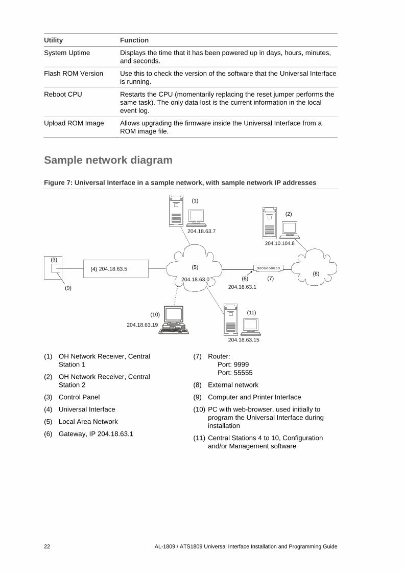
Sample network diagram
Figure 7: Universal Interface in a sample network, with sample network IP addresses
(1) OH Network Receiver, Central
Station 1
(2) OH Network Receiver, Central
Station 2
(3) Control Panel
(4) Universal Interface
(5) Local Area Network
(6) Gateway, IP 204.18.63.1
(7) Router:
Port: 9999
Port: 55555
(8) External network
(9) Computer and Printer Interface
(10) PC with web-browser, used initially to
program the Universal Interface during
installation
(11) Central Stations 4 to 10, Configuration
and/or Management software
204.10.104.8
204.18.63.19
204.18.63.0
204.18.63.1
204.18.63.7
204.18.63.5
(1)
(2)
(3)
(4) (5)
(6) (7)(8)
(9)
(10)
204.18.63.15
(11)
AL-1809 / ATS1809 Universal Interface Installation and Programming Guide 23
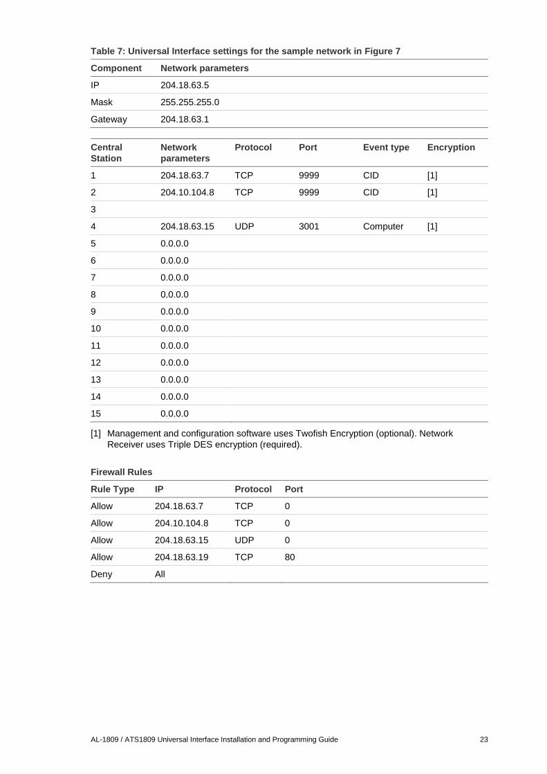
Table 7: Universal Interface settings for the sample network in Figure 7
Component Network parameters
IP 204.18.63.5
Mask 255.255.255.0
Gateway 204.18.63.1
Central
Station
Network
parameters
Protocol Port Event type Encryption
1 204.18.63.7 TCP 9999 CID [1]
2 204.10.104.8 TCP 9999 CID [1]
3
4 204.18.63.15 UDP 3001 Computer [1]
5 0.0.0.0
6 0.0.0.0
7 0.0.0.0
8 0.0.0.0
9 0.0.0.0
10 0.0.0.0
11 0.0.0.0
12 0.0.0.0
13 0.0.0.0
14 0.0.0.0
15 0.0.0.0
[1] Management and configuration software uses Twofish Encryption (optional). Network
Receiver uses Triple DES encryption (required).
Firewall Rules
Rule Type IP Protocol Port
Allow 204.18.63.7 TCP 0
Allow 204.10.104.8 TCP 0
Allow 204.18.63.15 UDP 0
Allow 204.18.63.19 TCP 80
Deny All
24 AL-1809 / ATS1809 Universal Interface Installation and Programming Guide
Specifications
Software
Configuration Mainly web browser after initial installation
Reporting format CID, SIA, or XSIA using OH Network Receiver
Software upgrade paths Upgradeable software obtainable from UTC Fire & Security
Reporting options Reporting to up to three OH Network Receivers using CID, SIA, or
XSIA.
Upload to Configuration and/or Management software.
Reporting backup PSTN dialler backup from CONTROL panel for alarm events to
central monitoring station
Encryption Triple DES encryption (OH Network Receiver)
128-bit Twofish data encryption (Management / Configuration
Software)
Network primitive frame size (bytes)
Ethernet frame 64 – 1522
IP Frame 20 + data
TCP Frame 20 + data
UDP Frame 8 + data
Hardware
Dimensions 50 x 170 mm
Power supply 12 VDC direct from battery or other 12 VDC source.
Backup power Directly connected to battery (deep discharge protected).
Current consumption 145 mA typical
Onboard status indicators LED indicators for:
• Ethernet link and activity.
• RS232 data transmit and receive.
Data connection from panel to
Universal Interface
RS232 connection from Universal Interface to Computer and
Printer Interface board on Control panel.
Board size UTC Fire & Security board size BB.
Data reset and refresh functions CPU reset via browser (“Reboot CPU”).
Data reset to factory defaults via jumper (‘DEF’).
“Restart Communications” via browser.
Working temperature −10 to +50°C
Max. relative humidity 95%, non-condensing
AL-1809 / ATS1809 Universal Interface Installation and Programming Guide 25
Installation worksheet Use this worksheet to record the details of the Universal Interface (UI), as
applicable to the particular installation.
Universal Interface parameters
Panel description Panel location
UI user name UI password
Network: From network administrator
Static IP Address
Net mask
Net mask host bits
Gateway address
Central Station parameters
Station IP Address Protocol Port Event Encryption
1
2
3
4
Panel Setup
Panel physical (Computer) address
Panel security password
Twofish encryption key
Network Receiver
Receiver number
Line number
Heartbeat Interval
Email/TFTP Parameters
Email address 1
Email address 2
Email address 3
Server IP address
Max number of events
Time to send email
Network Probing
26 AL-1809 / ATS1809 Universal Interface Installation and Programming Guide
Firewall parameters
Default firewall rule
Individual firewall rules (up to 20 permitted)
Number IP address Port Protocol Rule Type
1.
2.
3.
4.
5.
6.
7.
8.
9.
10.
11.
12.
13.
14.
15.
16.
17.
18.
19.
20.

AL-1809 / ATS1809 Universal Interface Installation and Programming Guide 27

28 AL-1809 / ATS1809 Universal Interface Installation and Programming Guide