Embed Size (px)
Citation preview
THE PETROLEUM SOCIETY PAPER 96-88
A.K.M. Jamaluddin, M. Hamelin, K. Harke, H. McCaskillNorcen Energy Resources
S.A. MehtaUniversity of Calgary
This paper is to be presented at the 47th Annual Technical Meeting of The Petroleum Society in Calgary, Alberta, Canada, June 10 - 12,1996. Discussion of this paper is invited and may be presented at the meeting if filed in writing with the technical program chairman priorto the conclusion of the meeting. This paper and any discussion filed will be considered for publication in CIM journals. Publication rightsare reserved. This is a pre-print and is subject to correction. .
ABSTRACT
A novel matrix stimulation concept, formation heat treatment(FHT), which involves the application of intense heatfor thetreatment of water-blockage and clay-related formationdamage in water-sensitive fomrations was developed andtested in the laboratory. Initial bench-scale heating tests onwater-sensitive sandstone CQTU showed that heat treatment ~6WC can improve air penneability of a damaged core by50% above the initial penneability. Dramatic penneabilityincreases of 750% and 1£W% above the initial reservoirpenneability occurred at 800'C for the cores taken from thegas- and oil-bearing formations, respectively.
To prove the fHT technology in the field, anelectrical downhole heater was designed and constructed.After testing the heater on swface, the heater was loweredinto the target reservoir, 1.5-km downhole, heated up andretrieved from the wellbore. Results of the field test showedthat there was a significant increase in the post heat-treatmentgas injectivity. To quantify the heating effect, pressuretransient analyses on pressure falloff data were carried outand the post heat-treatment permeability was found toincrease by several folds. The field logistics and the field testresults are presented in this paper.
INTRODUCTION
MQst hydrocarbon-bearing (oil and gas) sandstone reservoirscontain clay materials, which have die tendency to swell incontact widi water-based foreign fluids or to migrate due tofluid velocity in the pore spaces. Operations such as drilling,completion, workovers, and stimulation often expose thebmation to a foreign fluid and cause formation damage. Suchdamage is usually more severe in horizontal wells, because ofdie longer exposure of d1e wellbore to d1e offending fluids. I
During the drilling and completion phases, d1e primarymechanisms of ncar-wellbore formation damage can beexplained by the following factors:
> pore-throat constriction, caused eid1cr by clayswelling due to incompatible fluids or by clay
migration,
> water blocking due to reduction in relativepermeability to hydrocarbon,
>- plugging widi drill solids and mud products, and
>- loading of d1e reservoir widi drilling or completionfluids.
Formation damage during drilling and completion has longbeen identified as a major problem. Preventive measures tostabilize clay swelling and migration, mostly consisting of the
use of various chemicals (e.g., KO) in the drilling orcompletion fluid, have been discussed in the literabJre.1-7Howeva-, prevention of clay damage is not always possible oreffective, and curative measures may then become necessary.Several curative methods have been attempted and presentedin the literature.a.I!
The most popular stimulation technique is hydraulicfracturing. This method is not always applicable or desirable(e.g., in water- or gas-flooding situations, zones containingactive bottom water or gas caps) or not economical (e.g., insome horizontal wells). Another approach is to stimulate the~-wel1b<.-e region using ~ids, Which dissolve either the clayminerals themselves (HF acid) or the surrounding formationrock (HO aJxi HF acids). Matrix-stimulation techniques usingacids have been applied to carbonate reservoirs for productivityimprovement In both hydraulic-fracturing and acid-stimtL~tion techniques, the proper design of the fluid system isvery important When the fluid systems contain fresh Water,the chances of further clay swelling and migration are
particularly high.
Ovu: dle years, various thermal p-ocesses have been~ to improve oil production. One of the earliest reports ofin-situ thermal treatment was that of Albaugh, 16 on a field test
that was carried out in an oil well. An incremental oilproduction of 16 bbVday was demonstrated by that field testSubsequently, many other curative thermal processes havebeen descrIbed roc variety of purposes including the removal ofwaxl7 or asphaltenel8 buildups, thennal fracturing of theformation. 19 and the consolidation of unconsolidated
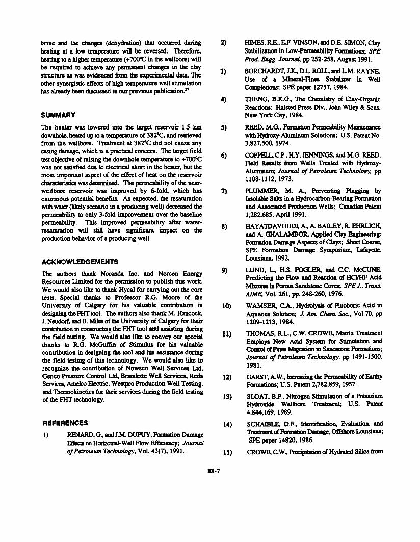
formations.» More specifically related to clay damage aremethods aimed at dehydrating clays at lorl or hightemperature,19 transforming a sensitive type of clay (e.g.,smectite) into a less sensitive type (e.g., i1lite),n Or simplyremoVing water by evaporation.%3.2A It is a well-known fw;f'd18t ~ lattice structure of almost all clay mjnera1s responds tothermal shock and that the degree of change in the latticeSInJCQJre ofvarious miIaals depends on d1e temperature level.This phenomenon is exploited routinely in d1e laboratory fcxclay determination. For instance, the effect of a one-hourheating period at certain temperatures on some selective clayminerals is shown in Table 1. Based 00 d1ese temperatureeffects on clay structure, a novel matrix-stimulation conceptwas designed and tested in d1e laboratory.
> vaporization of blocked water,
> dehydration of the clay StnlCture,
> partial destruction of d1e clay minerals, and
> possibly, micro-fracture of the fonnation in die near-wellbore area due to thermal induced stresses.
The deh:>dration and vaporization of bound and blocked wateroccur at temperatures higher than the sattlration temperaturecorresponding to d1e reservoir pressure. The extent of claydestruction also depends on the heating temperanue.
To validate die FHr concept, a series of bench-scaleheating tests was carried out on sandstone cores taken frombod1 oil- and gas-bearing formations to detcm1ine the effect ofheat on pemJeability, fluid saturation. and mineralogy (i.e.,degradation of in-situ minerals). Experimental temperatures(i.e., 200, 400, 600, and 8000C) were selected based on dieliterature data25 presented in Table 1. The initial oil or gaspermeability was measured to establish the baselinepermeability. Each core was dien subjected to the followingsequence of conditions:
> exposure to formation brine,
> exposure to mud filtrate,
> high temperatule treabnent, and
> exposure to formation brine.
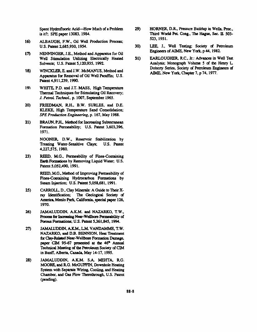
During each sequence, the core was saturated widi dierespective fluid, dcsaturatcd and eidia- air or oil pem1eabilitywas ~ . The 1ating of the cores was carried out widlina~. The ~ was ~miDed at a pressure higher thandx:ca:res poIKling reselVoir pressure using a regulated nitrogensource. In each case, the core was exposed to selectedtemperatures aM d1cn allowed to cool to room temperatule.Subsequently, the effective pemJeabiIity to either oil or gas(depending on the reservoir type) was determined. DetailedexperlDaIal setup, procedure and initial two-test results werepublished earlia-.%7 Ackiitionai results are presented in Tables2 and 3.
As seen in Table 3. the Boyer Bluesky fOmlationdisplayed an 84% reduction in pemability following brineam DIx1 filb:afC exposure. Subsequent beating results showeddIat the baseline petmeability of the core can be reestablishedafter exposing the core to a temperature of 40()0C. However.the changes in permeability at this temperature may not be~ This is ~use of the fact d1at clay materials maynot have been aff~ by the heating at 4O()OC and theimprovement may be due to dewatering only. Reexposure towater may reverse the damage and d1is is the most likelyscenario to occur in a real hydrocarbon producing well.Further heating at 6OO"C improved the permeability of the
FHT CONCEPT AND LABORATORY TESTING
The process involves the application of heat for the~ of near-wellbore damage. The process.%6 formationheat treatment (FHI). consists of exposing die formation to anelevated temperature to cause:
88-2
losses in die wellbore, an exttemely high superheated steamcondition at the surf~ would be required to ~hieve adownhole temperature of 800"C. Injection of steam will also~ spc:jal t)1Je of weUbore casing. In I(kjitiOD. steam will~ into wafer in dx: ~ir aOO will defeat die purposeof the FHT process.
Among od1~ existing d1emIal processes, thecombustion process is JX)tentia11y attractive. Similar to thesteam process, the combustion process also requires extensive~ ~ties. In addition, the combustion-front movementin a gas or light oil reservoir has not yet been studied becausedie IX'OCeS5 is only used for heavy oil awlicalions.
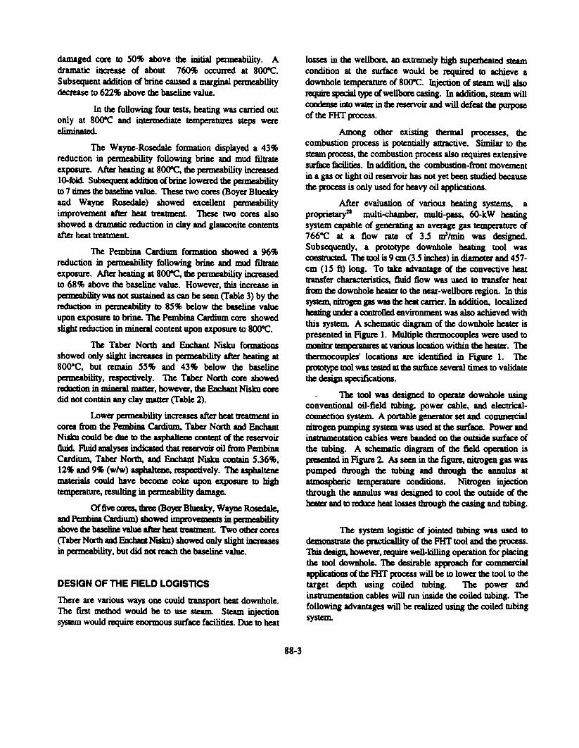
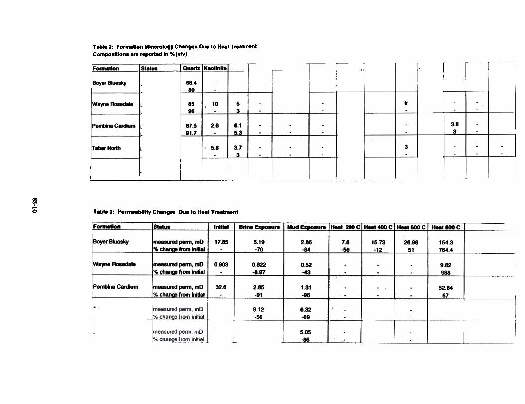
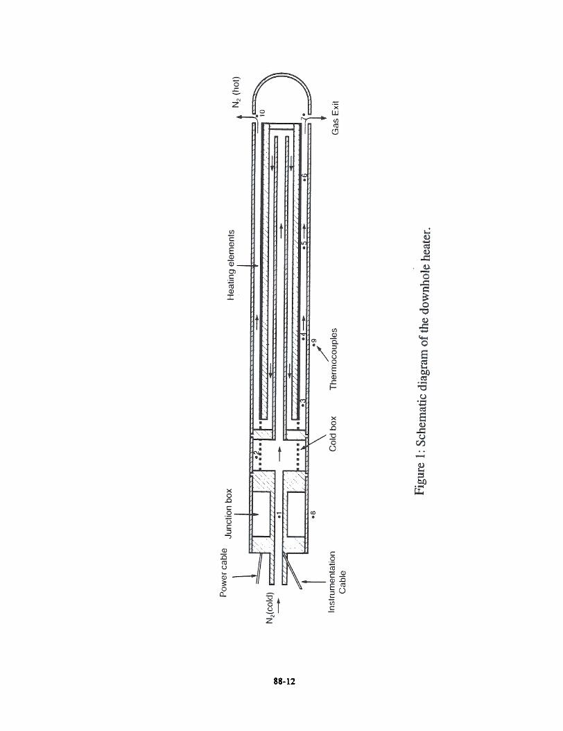
After evaluation of various heating systems, aprolXietary21 multi-cbamber, multi-pass, 6O-kW tatingsystem capable of ~g an average gas tempetature cS766°C at a now rate of 3.5 m3/min was designed.Subsequently, a p-ototype downhole heating tool was~ The UX)J is 9 an (3.5 iJr;hes) in diameter and 45 7 -cm (15ft) long. To take advantage of die convective beattransfer characteristics, fluid now was used to transfer heatft'CXD die downhole beater to the near-weU~ region. In this~ iiiti"-up gas was dx: tat carri~. In ~tion, l~-w~tating wxJer a m1troDcd enviro~nt was also achieved withthis system. A schematic diagram of die downhole beater ispresented in Figure 1. Multiple thermocouples were used toDXXIib' ~aDJreS at varDJS kx:ation within die heata-. Thethermocouples' l<x:ations are identified in Figure 1. The~ tool was tested at dx: surface several times to validatedie design specifications.
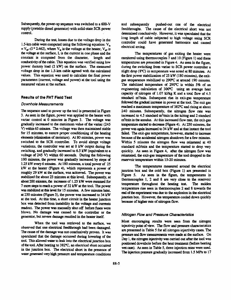
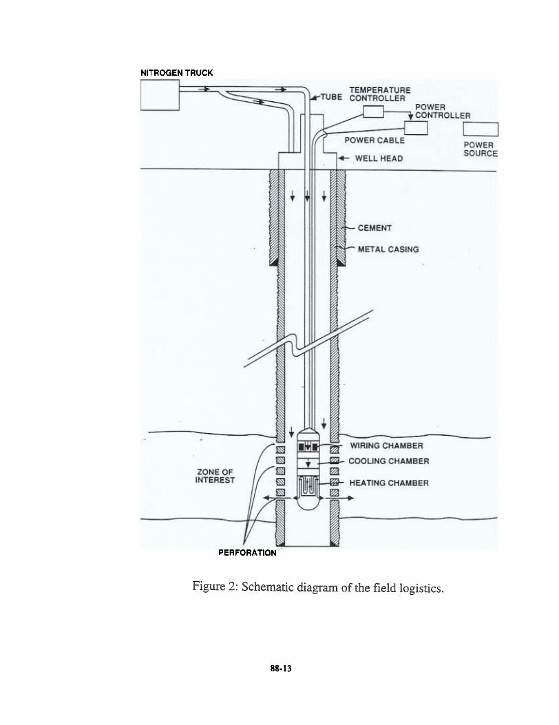
- The tool was designed to ~ oownhole usingconventional oil-field tubing, power cable, aOO electrical-~on system. A portable generBtor set aOO co~mtrogcn pumping systtm was used at die surface. Powa- aOOinstrtc!~ntation cables were banded 011 die outside SUIface ofthe blbing. A schematic diagram of die field operation isIX'raCDtcd in Figure 2. As ~ in the figure, nitrogen gas waspumped through the tubing aOO bough the annulus atatmospheric temperanIre coOOitions. Nitrogen injectionthrough the annulus was designed to cool die outside of the~ am to 1uhx:e heat losses through d1e casing and blbing.
damaged C<Xe to 50% above the initial ~ility. A
dramatic iDCrase of about 760% occurred at 8000C.
Subsequent ICkiition of brine caused a marginal permeabilitydecrease to 622% above the baseline value.
In die following four tests, heating was carried outonly at 8000c and intermedi!~ temperatures steps wereeliminated
The Wayne-Rosedaie formation displayed a 43%reduction in penneability following brine and mud filtrateexp>sure. After heating at 800"C, the permeability inaeased10-foki S~~ aIibcX1 ofbriDC lowered the pcm1eabilityto 7 tiDx:s ~ ~cetine value. These two cores (Boyer Blueskyand Wayne P_osedale) showed excellent permeabilityimprovement after beat ~nt These two cores alsoshowed a dramatic reduction in clay aOO gla!x:oDite contentsafter heat treatment
The Pembina Cardium formation showed a 96%reduction in permeability following brine aOO mIM1 filtrateexposure. After heating at 8000c, the permeability inaeasedto 68% above d1e baseline value. However, this increase inpaoDability was oot SI-L-ct-3L~ as can be seen (fable 3) by d1ereduction in ~lity to 85% below the bueline valueup>n exposure to brine. The Pembina Cardium core showedslight reduction in mineral content up>n exp>sure to 8000c.
The Taber Ncxth aM ElK:bant Nisku fcxmalioosshowed only slight increases in permeability afta' heating at800.C, but remain 55% and 43% below the baseline~ility, respectively. The Taber NMh C<Xe showedreckx:tion in miDeIal matter', however, d1e F~t NISkD ~did DOt contain any clay matter (fable 2).
Lower pemleability increases after beat treabnent incores from the Pembina Cardium. Taber Ncxth aM ElK:hantNisku ~ be due to d1e aspbal~ CODteIJt d. b reservoirdun fluid analyses !~icafed that resavoiI oil from PembinaCardium. Taber Nord1. aM ~~ Ntsku contain 5.36%,12., aOO 9411 (w/w) aspbaiteDe. ~-tively. The aspbalfenematerials could have beco~ coke upon exp>sure to hightemperature, resulting in permeability damage.
Of ~ (XI'es, ~ (BO)a' Bhaky, Wayne Roseda1e,aJxi PeIImiDa Cardium) showed impro~ in pauabilityabove ~ ~~~ value afta' heat trcabnent Two other ~(faber Nath aJxi EI¥:ham. Nisku) showed only slight iJx:reasesin ~ility, but did Dot re-=b d1e ~celine value.
The system logistic d jointed b1bing was used todemonstrate the practicallity of the fHT tool and the process.This dtsign. ~. require ~-killing ~n for placingthe tool c:k>wnbole. The desirable approac:b fIX' commefcialawlk:aliom d.dIC Rrr 1X'QCeSS will be to low~ the tool to thetarset depth using coiled tubing. The power andinSbumentation cables will nm inside die coiled tubing. Thefollowing advantages will be realized using the coiled tubing
system.
DESIGN OF THE FIELD LOGISTICS
There are various ways one could b'8nsport beat downhole.The flISt mediad would be to use steam. Steam injectionsystem would ~ enormous surface facilities. Due to heat
88-3
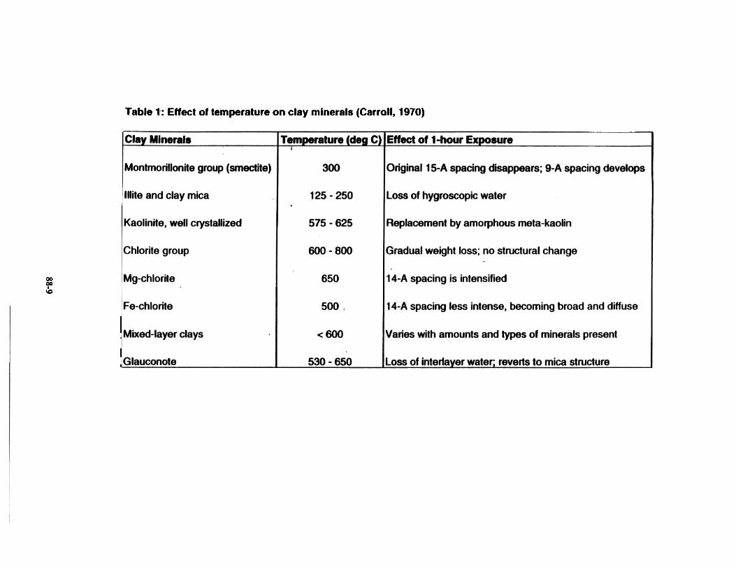
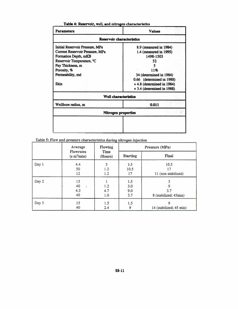
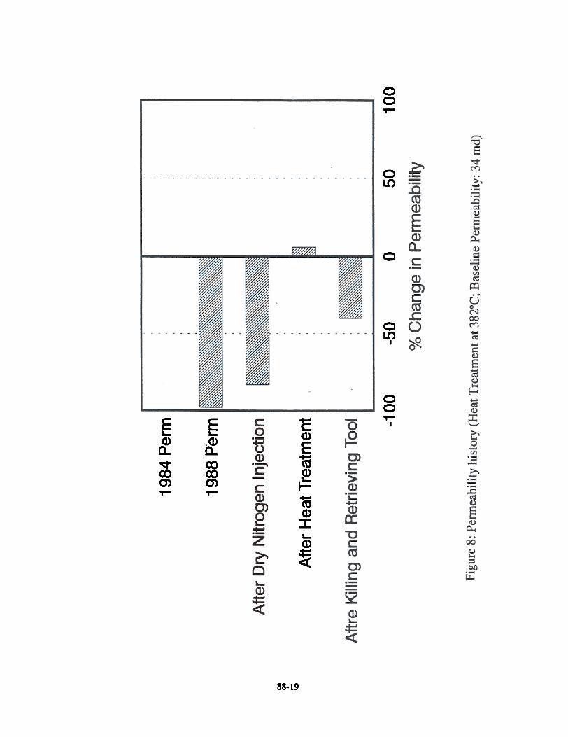
>- BOOt permeability values (Table 4) were determinedusing pressure transient analyses. As seen in Table 4, diereduction in permeability from 34 axI to 0.66 DId during theproduction life of ~ weD was believ~ to be the result of fmesmigration and water sattll'ation. The weD was drilled usingwater-based mx1 aM a skin value of +4.8 was determined fromdie initial pressure buildup analysis in 1984.
>-
Tool placement 'operation can be achieved in livewells (no well-killing operation required).
The tool can be moved for multi-depd1 stimulation.
Coiled tubing ~ will be applicable in stimulatinghorizontal wells.
>-
Field-Testing SequenceThe fHf prtx:esS was field tested on June 29, 1995. The f1frtool was surface tested on location before it was lowered intothe target depth of 1.5 km. The power and instrumentationcables were banded on the surface of the tubing. The beaterwas pov.ued up downhole slowly. During the field operationthe following ~uence of events took place:
Day 1
>- Kill the well widt KO water, lower the tool, andsetup the surface power, iDstrumentation and flow
systems.
>- Blowout the well, pressurize the well with nitrogen.establish the nitrogen feed rate, shutin the well andmonitor the pressure falloff overnight.
Day 2
>-
FIELD TESTING OF THE FHT PROCESS
Field Test Objective
The objective of dte field test was to prove d1e practicalfeasibility of dte FHr tool and dte process using a well slatedfor abandonment To realize this objective, we set dtefollowing targets:
>- Primary Targets:
- lower the FHr tool to the sandface,
- heat dte tool to about 700"C.
- retrieve d1e tool, and
- identify casing deformation.
>- Secondary Targets:
demonstrate inCIease in gas injectivity.
Although it is desirable to achieve a nitrogentemperature of 8000c, the target temperature for d1e field testwas set at 7000c because of flow and power combinationsachievable using dte FHr tool.
Pressurize the well. cut the nitrogen flowrate to thepreset rate. slowly heat dJC wellbore for a desiredtime. cool dJC wellbore. pressurize again. shutin thewellbore and monitor the IX'e5S1Jre falloff overnight
Day 3
>0 Kill d1e well with KCl watCI', rettieve d1e tool,pressurize the wen. shutin the well and monitor d1epressure falloff characteristics.
During d1e beating test, preset constant nitrogen flow rates\\Ue main!:BL~ dU'OOgh d1e tubing and the annulus. Nitrogenflow from d1e nitrogen pumping truck was split into tubingflow and annular flow. Constant flow rates were maintainedusing two Bow ~ am back-fiow regulators in d1e two flowlines. During d1e test, a constant flow rate of 3.5 standardm3/min was mAintained in die tubing aOO a flow rate of 1.0standard m3/min was main~L~ in the annulus.
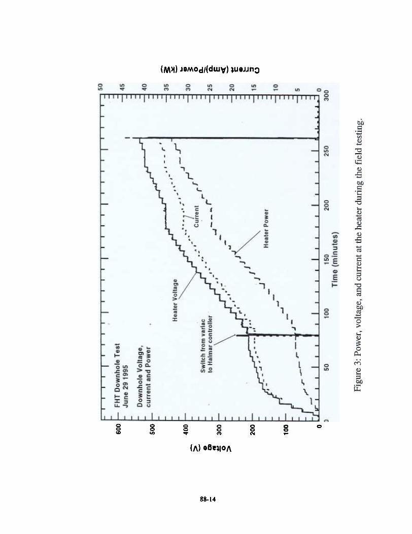
In die surface power setup, two manual switches wereinstalled to allow powering of the heater from either the 240 Vsupply widt variac controls or 600 V supply widt solid-statesilkon-controlled rectifier (SCR) power control. The downholebcata' was ~up slowly first using a variac control froma 24(). V powa' SOW'CC (rig generator). The initial slow power-up sequence was used to maintain a low voltage input to d1eheating elements and allow the heating elements to warmup.
'\
Well and Reservoir CharacteristicsTo satisfy the objective of the field test. Norcen Mcleod well#16-17-55-14W5 was selected. This well was completed inCardium fixmation. produced for about 6 y~ and was slatedftx' abaIxbDmeot due to depletion. The well was suspended in1993 due to low gas productivity.. An absolute open flowpotential for d1is well was detcnnined to be 210.000 m3/day.On average, the ~ produced 4O.(XX) m3/day of gas comprisedprimarilyoflJx:dJaDe (83% by mole). edJane (5% by mole) and~ (4% bYIOOIe). The ~ produced a tota1 of 73 millionmJ of gas. 434 In' of condensate and 205 In' of watec. Theformation characteristics are ~ in Table 4.
Results on core analyses showed that d1e net-payinterval consisted primarily of shale. chert, and ~tone.Roughly 60% of the core material was medium to dark-greyshale. The shaly material also displays slightly glauconitic~ ~ remaining composition includes 15% chertfragments. 15% grey- to light-brown siltstone. and 10%sandstone.
88-4
Sub~uendy, dJe power-up sequerx:c was switched to a 600- Vsupply (P<X'fable diesel generator) with solid-state SCR powercontrol.
During the test, losses due to the voltage drop in theI.S-kIn cable wa:e computed using the following equation: V M= V 8f -(I . 2.462), where V. is the voltage at the beater, V 8f is
the voltage at the surface, I. is the current in one phase and theconstant is computed from the diameter, length andcorxluctivity of the cable. This ~uation was verified using lowpower dummy load (2 kW) on the surface. The measuredvoltage drop in the 1.S-km cable agreed with the calculatedvalues. This ~uation was used to calculate the final powerparameters (cun-ent, voltage and power) at the tool using themeasured values at the surface.
and subsequently pushed-out one of the electricalfeedthroughs. The cause of the electrical short was notdcttm1ined conclusively. However. it was specul~ that thelong length of cable subjected to high voltage using SCRcontroller could have generated harmonics and causedelectrical arcing.
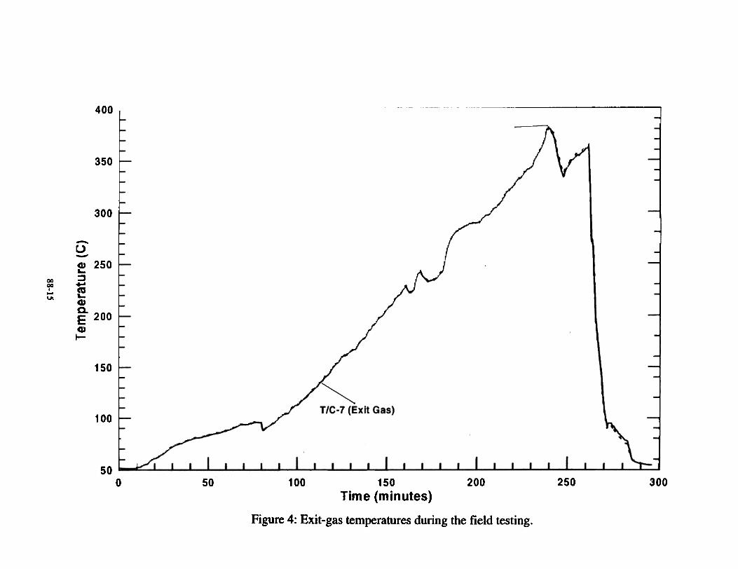
The temperatures of gas exiting the beater wereIOOnitaed using diermocouples 7 and 10 (Figure 1) and diesetemperatures are presented in Figure 4. As seen in the figure,during the switching from variac to SCR power controller aslight drop (8OC) in temperature was noted at 80 minutes. AtdlC first power stabilization of 25 kW (180 minutes), the exit-gas temperature stabilized to 29OOC at around 190 minutes.The stabilized temperature of 2900c is widlin 5% of anengineering calculation of 3000c using an average heatcapacity of nitrogen <i 1.07 kJ/kg K and a total flow of 4.5standard m]/min. Subsequent rise in exit-gas temperaturefollowed dlC gradual mease in power at d1e tool. The exit gas~hed a maximum temperabUe of 382OC and rising at about240 minutes. Subsequently, dlC riitrogen flow rate wasincreased to 4.5 standard m]/min in d1e tubing and 2 standardnf/min in dlC annulus. At dtis increased flow rate, die exit-gastempezatm'e started to decrease (Figure 4). At 250 minutes, thepower was agajn iIn'e8Sed to 34 kW and at that instant d1e toolfaikd The exit-gas temperature, however, started to increase~ ofdlC accidental nitrogen shutdown f<X' a few minutes.Within 5 minutes die nitrogen flow was reinstated at 40standard m3/min and the temperature started to drop veryquickly. As seen in Figure 4, after d1e nitrogen flow wasrei-11..V~t~ d1e exit-gas temperature of die tool dropped to thereservoir temperature within 15-20 minutes.
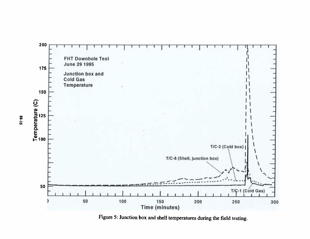
The temperamres measured arowxi d1e electricaljunction box and the cold box (Figure 1) are ~nted inFigure 5. As seen in the figure, d1e temperatures inthermocouples 1, 2 and 8 are very close to d1e reservoirtemperature throughout d1e heating test The suddentemperature rise seen in thermocouples 2 and 8 towards d1eeIx1 of die~ IIaIt was due to d1e explosion in the electricaljmx:tion box. Howev~, d1e ~ cooled down quicklybecause of higher rate of nitrogen flow.
Nitrogen Flow and Pressure Characteristics
Most encouraging results were seen from the nitrogeninjectivity point of view. The flow and 1XCSS\Irc characteristicsare presented in Table 5 for allni~gen injectivity cases. TheIXe55Ure aOO Bow ~ts ~ made at the surface. OnDay 1. dx: nitrogen injectivity was carried out after d1e tool was~ downhole before the beat tIeatment (before heatingwet case). As seen in Table S. d1rcc injection rates w~ usedThe injection pressure gradually increased from 1.5 MPa to 17
Results of the FHT Field Test
Downhole Measurements
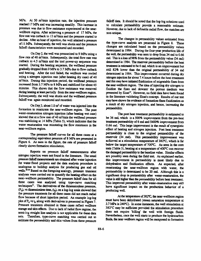
The sequeoce used to power up the tool is IX'C$ented in Figure
3. As seen in the figure, power was applied to the heater with
variac control at 0 minutes in Figure 3. The voltage was
gradually increased to the maximum value of the variac (245
V) widlin 65~. The voltage was then maintained stable
for I 5 minutes. to ensure proper conditioning of the heatingeleuats (eliminaIion of moisture). At 80 minutes, power was
switched to the SCR controUer. To avoid abrupt voltage
variations, the controUer was set at 0 kW output during theswitching, and ~y increased to 6.5 kW (equivalent to avoltage of 245 V) within 60 seconds. During the following1 00 minutes, the power was ~y increased by steps <t"1.25 kW evezy 6 minutes. At 180 minutes, a total power of 25
kW at the heater (Figure 4), which represents a power ofroughly 29 kW at the surface, was achieved. The Power was
stabilized for about 23 minutes at this level. Subsequently, at
&boot 200 minlrt~1 dJC iJx:l8ases of 1.25 kW were resumed for7 IIQ'C steps to reach a power of 32 kW at the tool. The pow~was s13bilized If. dJis level tc.' 15 minutes. A few minutes later,
If. 250 minutes (Figure 3), the power was increased to 34 kWat the tool. At this time, a short circuit in the heater junction
box was detected from instability in the voltage and currents
readout The power was ~ual1y shut off before fuses wereblown. No damage was caused to the controUer or thegenerator, but severe damage resulted in the heater itself.
When the tool was retrieved to the surface, weobserved that one electrical feedthrough had been damaged.
The cause of the damage was not conclusively proven. It was
speculated that the damage occUlTed during lowering of thetool. This aUowed water to leak into the electrical junction boxofdJC tooL Aftec heating to 382OC, an electrical short occurredin the junction box. The electrical short in the presence <iwater ~ va-y high pressure and temperature conditions
88-5
MPa. At 50 m3/min injection rate, the injection pressurereached 17 MPa and was increasing steadily. This increase inpressure was due to flow resistance experienced at the near-weUbore region. After achieving a pressure of 17 MPa, theftow rate was cutback to 12 m3/min and the pressure started todecline. After an hour of injection, the wen attained a pressureof 11 MPa. Subsequently, the well was sbutin and the ~falloff characteristics were monitored and recorded.
On Day 2, the wen was pressurized to 9 MPa using aflow rate of 40 m3/min. Subsequently, the total flow rate wascutback to 4.5 m3Jmin and the tool power-up sequence wasstarted. During the beating sequence, the wellhead pressuregrOOually di-\Ji)pe(1 ftom 9 MPa to 3.7 MPa due to flow cutbackand heating. After the tool failed, the weUbore was cooledusing a nitrogen injection rate (after heating dry case) of 40m3/min. During this injection period, the wellhead pressureincreased from 3.7 MPa to 8 MPa and stabilized for about 45minutes. This shows that the flow resistance was removedduring Iating at least partially from the near-weUbore region.Subsequently, the wen was shutin and the wellhead pressurefalloff was again monitored and recorded.
On Day.3, about 1.0 nr of water was injected into theformation to resaturate the near-weUbore region. The postwater-resablration nitrogen injection (after heating wet case)showed that at a flow rate of 40 m3/min the wellhead pressurewas stabilizing at 14 MPa (Table 5), which indicates that thcwater resaturation was reinstating the flow resistance in thenear-weUbore region.
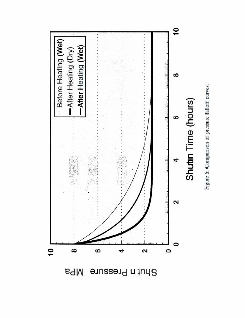
The pressure falloff curves for all three cases at acorresponding equivalent pressure of 8 MPa are presented inFigure 6. As seen in the figure, the rate of pressure falloffclearly shows formation stimulation.
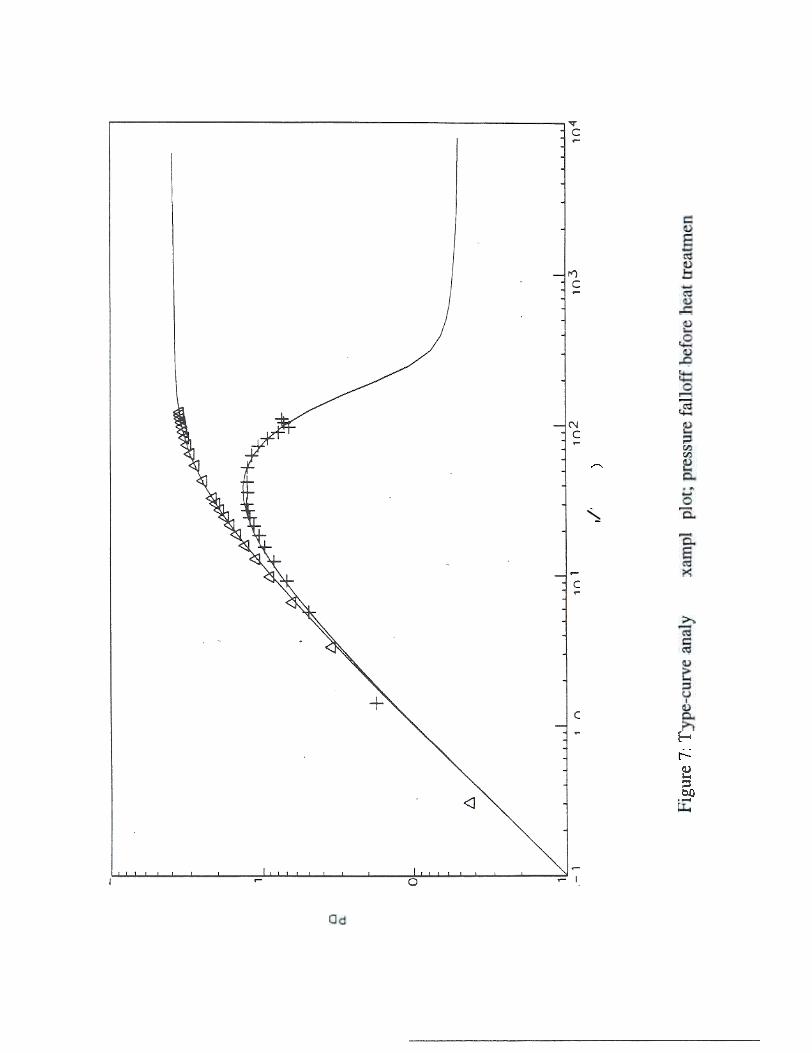
Reports on pressure falloff measurements afternitrogen injection were not found in the literature. The usualpressure faDotfDas1 JreII'enfs are obtained after water injectionfcx- Water-flood JX'Ojects and the data analysis procedure isanalogous to buildup analysis for producing gas and oilweUs.19.30 Based on the foregoing analogy, pressure transientanalyses were carried out to quantify the beating effect on thenear-weUbore permeability. The pressure falloff data for allthree cases was analyzed using type-curve matchingtechniques31. The derivatives of the dimensionless pressure,(PO>, vs ~ooas ~ (10), on a log-log sca1e showed thatthe pressure ttansients for all three cases did not reach radialflow because of short injection period. An example log-logplotofPD vs to along with derivatives is presented in Figure 7.Pressure ttansients obtained in these cases reflect weUborestaage and skin effects. Due to lack of radial flow regime, thesemi-log straight line analysis is not applicable for these datasets. Therefore, type-curve matching was carried out toestimate the pemleability and skin values from these pressure
falloff data. It should be noted mat the log-log solutions usedto calculate permeability JX'Ovide a reasonable estimate.Howeva-, due to lack of definable radial flow, the matches are
non-unique.
The changes in permeability values estimated fromdie type-curve analysis are p-esented in Figure 8. Thesechanges are calculated based on the permeability valuesdetemlined in 1984. During the four-year production life ofdie well, die pernability was seen to drop from 34 rod to 0.66DKl This is a loss of98% from the permeability value (34 md)~ in 1984. The ~ permeability before the heat~ is ~ to be 6 aKi, which is an improvement butstill 82% lower than the original permeability of 34 nxIdetermined in 1984. This improvement occurred during drynitrogen injection b about 7.4 hours before the heat treatmenta1¥i this may have initiated fluidization of migratible fines fromthe rar-wellb<Xe region. The idea of injecting dry nitrogen tofluidize the fines and dewater the porous medium wasJX'e5eQted by Sloat!3. However, no field data have been foundin the litcranue validating Sloat's concept. Results of our testDY have s!MJwn the evidcI¥:e of fonnation-fines fluidization asa result of dry nitrogen injection, and hence, increasing dte
permeability.
The post heat ~tment pemlcability is estimated tobe 36 oxI, which is a 500% improvement from the pre-heat1reab1at pernability of 6 rod and 5400% improvement from0.66 md. This large improvement is die result of synergisticeffect of heating and nitrogen injection. Post heat treatmentpermeability is close to the original permeability of thereservoir (34 - md). This permeability improvement wasacf1iev~ at a s~um!:ion temperature of 382oc. which is farbelow the target temperature of 7000c. As seen in die core~ (fable 3), heating at a temperature of 4OOOC can recoverdie damaged pernability to b baseline value. Similar effectsare possibly seen during die field test As explained earlier,this iIDIXOvemeDt in permeability is most likely due todehydration and fluidization effects. As expected, afterresaturating the near-weDbore region with water, thepermeability is detetmined to be 20 m Although this is asignificant drop in permeability after water-resabJration, dieval~ is still bigta' dIaD bpermeab ility before heat ~unentThis improved pemleability after water-resabJration may stillhave significant impact on the lXoduction behavior of aproducing weD.
At the ~~ of38~ the lar-weDbore regionmust have been ddlydrated (steam saturation temperature at3.7 MFa is 24OOC). In some instances. me weD stimulation at382°C may be sufficient provided me stimulation proc~uredoes not require 'killing' die weD with foreign fluids.N~less, once the well starts to produce die hydrocarbonfluids, b rar-weIlbore region will be reexposed to fonnation
88-6
brine W the changes (dehydration) that ~ diningheating at a low temperature will be reversed. Therefore,~ to a higher temperablre (+7000c in the wellbore) willbe required to Khieve any permanent changes in tile claysttucture u was evideIK:ed from d1e experimental data. Theother synergistic effects of high temperature well stimulationhas already been discussed in our pevious publication. 27
2)
3)
4)
SUMMARYThe heater was lowered into the target reservoir 1.5 kIDdownhole. heated up to a temperabue of 382oc. and retrievedfrom the wellbore. Treauncnt at 382°C did not cause anycasing damage, which is a practical concern. The target fieldtest ob~ve of raising the downhole tempet'anlre to + 7000cwas not satisfied due to electtical short in the beater. but themost important aspect of the effect of beat on the reservoir~ was detamincd. The permeability of the near.wellbore reservoir was improved by 6-fold. which basenormous potential benefits. As expected. the resaturationwith Waf« (1ike1y sceoario in a producing well) decreased thepermeability to only 3.fold improv~nt oVC' the baselinepermeability. This improved pemleability after water-resaturation will still have significant impact on theproduction behavior of a producing well.
5)
6)
7)
8)
9)ACKNOWLEDGEMENTSThe authors thank Noranda Inc. and Norcen EnergyResources Limited for the pennission to publish this work.We would also like to thank Hycal for carrying out the coretests. Special thanks to Professor R.G. Moore of dieUniversity of Calpry for his valuable contribution iniWigning dJe f1ff tool. The authors also d1ank M. Hancock.J. NeImf, am B. MiJes of dJe University of Calgary for theircontribuOon in con stnJctiDg1be FHr toolalfd assisting duringthe field testing. We would also like to convey our specialthanks to R.G. McGuffin of Stimulus for his valuablecontribution in designing ~ tool aM his assistaDce duringthe field testing of this technology. We would also like torecognize the contribution of Nowsco wen Services LId.Genco Pressure Control Ltd. BraDdcac wen Services, Rcda~ Amcko EIec1ric, Westpro Production Wen Testing,and Themlokinetics for their services during the field testingof the FHr technology.
10)
11)
12)
13)
14)REFERENCES
1) ~ARD, G.. aIx1 J.M. DUPUY, FcxII8Iion DamageEtrcc1S on HcxizODJal-weU How Efficieav;y; Journalof Perrouum Technology, Vol. 43(7),1991.
~. R.E.. E.F. VINSON.1Ixi D.E. SIMON. ClayStabilimtion in Low-Pemability FcxmaIiom; SPEProd. Engg. Jolmlal, pp 252-258. August 1991.
BORCHARDT. J.K.. DoL ROlL. and L.M. RAYNE.Use of a MiDn-rua Stabilizer in WellComp1etioa; SPE paper 12757. 1984.
rnENO. B.K.O.. The O1emistry of Clay-OrganicReactions; Halstcd Press Div.. John Wiley &; SODS.New York City. 1984.
REED. M.O.. FonDaIion Permeability M.L~tenancewid1 ~Aluminum Solutions; U.S. Patent No.
3.827,500.1974.
CO~ C.P.. H. Y. JENNINGS. aM M.G. REED,Field Results fnxn Wells Treated widt Hydroxy-Aluminum; Journal of Petroleum Technology, pp1108-1112.1973.
PLUMMER. M. A. Preventing Plugging byInsoluble Salts in a Hydrocaibon-Bearing Formationand Associated Production Wells; C~~adian Patent1.282,68'. April 1991.
HAY A mA VOUDI, A.. A BAn.EY. R. EHRLICH,
aM A OHALAMBOR. Applied Cay BngL~g:Fc.~ii Damage Aspa:ts of Clays; Sbcxt Course.SPE Formation Damage SYIDP>Sium. Lafayette,Louisiana. 1992.
LUND. L.. H.S. ~ IIx1 C.C. McCUNE,Predicting the How and ~on of HC/HF AcidMixtm'es in PCXtXJI Sandsto~~; SPE J.. Trans.A1ME, Vol. 261. W. 248-260. 1976.
WAMSER. CA. Hydrolysis of Huoboric Acid inAqueous Solution; J. Am. Ch4n1. Soc.. Vo170. pp1209-1213.1984.
'IHOMAS. R.L.. C. W. CROWE. Matrix TreaDIlentEmpkJys New Acid System f(X' Stimulation aDdOxmd «RIa Migration in SaIKistone F«mations;Journal of Petroleum Technology. pp 1491-1500.1981.
GARST. A W.. Isgasing the PemJeability of EarthyFormations; U.S. Patent 2,782,859. 1957.
SLOAT. B.P.. Nitrogen Stimulation of a PotassiumHydroxMie WeUbcxe T~t; U.S. Parent4.844.169. 1989.
SCHAIBLE. D.P.. ldentificalion. Evaluation. aDdTi~7'~~«~ DaDmF. ~ Louisiana;SPE paper 14820.1986.
CROWE. c. w.. Ci.x:i[.iiaaK.i of Hydrated Silica from15)
88-7
29)
16)
30)
HORNER. D.R. Pressure Buildup in Wells. Proc..Third World Pet. Cong..The Hague. Sec. n. ~O3-~23. 19~1.
LEE. J., Well Testing; Society of PetroleumEJI-!i~ of AIME. New York. p44.1982
EARLOUGHER. RC.. Jr.: Advances in Well TestAnalysis; Monograph Vol~ ~ of die Henry 1.Doherty Series. Society of Petroleum EngL~ c:iAIME. New York. Chapter 7. p 74, 1m.
17)
31)
18)
19)
20)
21)
23)
25)
26)
27)
28)
Spent Hydrofluoric Acid-How Much of a Problemis it?; SPE paper 13083, 1984.
ALBAUGH, F.W., Oil Well Production Process;U.S. Patent 2,685,930, 19~.
NENNnolGER, J .E., Method and Apparatus for OilWell Stimulation Utilizing FJ~tticaUy HeatedSolvents; U.S. Patent 5,120,935, 1992.
WnolCKLER, E. and J. W. McMANUS, Method andApparatus for Removal of Oil Well Paraffin; U.S.Patent 4.911,239, 1990.
WHn"E, P.D. and J.T. MASS, High T~ThC1'Inal Techniques for Stimulatina Oil Recovery;J. PetroL TechnoL. p. 1007. September 1965.
FRIEDMAN, RH.. B. W. SURLES, and D.E.KLEKE, High Temperature Sand Consolidation;SPE Production Engineering. p. 167. May 1988.
BRAUN. P.H.. Med1od fCK bx:reasing SubterraneanFormation Permeability; U.S. Patent 3,603,396.1971.
NOONER. D. W.. Reservoir Stabilization byTreating Warer-Seusitive Cays; U.S. Parent4.227.575. 1980.
REED, M.O.. Permeability of Fines-ContainingEIrd1 F<xmatM>DS by Removing Liquid Water; U.S.Patent 5.052,490, 1991.
REED, MO.. Method of Improving Permeability ofFines-Containing Hydrocarbon FomIatiODS bySleam Injection; U.S. Patent 5,058,681, 1991.
CARROlL, D.. Clay Minerals: A Guide to Their X-ray Identification; The Geological Society ci~ Menlo Park, California, special pIptt' 126,1970. - .
JAMALUDDm, A.K.M. and NAZARKO, T.W.,~ b m-~ N... WdIbore Petmeability ofPorous Fcxmatiom; U.S. Patent 5.361,845, 1994.
JAMAJ.JJDDm, AKM..l..M. VANDAMME, T. W.NAZARKO, aI¥I D.B. BENNION, Heat Treatmentb aay.Rd8Jd Near- WeUbore Formation DaJDaae,papa' CIM 95-67 ~~ at die 46* AnnualT~hnica1 Meeting cI. die Petroleum Society of CIMin Banff. Alberta, Canada. May 14-17. 1995.
J AMAL UD D m . A.K.M S .A. MEHr A. R. 0 .MOORE, aIKi R.G. McGUFFIN, Downhole HeatingSystem widt Separate Wiring. Cooling. and HeatingChamber. and Gas Row Therethrough. U.S. Patent
(pending).
88-8
-Q,...~~-"0....~(..)-~"i..Q
).5E>
-~uS!=-~..!.EQ
)--0-~w..~C
)::a~
~
.'!!i>.t5 G)
~=~&~w~=0of~'0im:
"i"-~i-c..~e0)G
)-'2..2
:c0E-c0~ 8(') f/)0-0~>Q)
'00)c°u~0-f/)
<I
0)~tUQ)
0-0-~:e0)c'(3tU0-f/)
<I
In-"(ijc.~'ca
~(,)
"e>-
~U'CC~Q)
~ 0It)N,It)N- ...Q)
'i~CJ
"5.0~e~.c'0~0-J
"i~"i-(/)
2:-
tJ
'IG)
-:5'0co
~ ~~I
~"""~ .~"'0ca~
I
ca
~(/)~0-e.0Eca>
..c'!~E§'Q
.~~
Co
~e0)Q)
-"C0:EU ~I0~ Q)
0)c~..cQ!~U2"US
0c~U)
..2-..c0)
'I"i~"C!~
~-c0:2(,)I0)
~ 0I()<
0
'0~.."inc~-,~,~0)c"0~0-ct)
<I
~-88-9
~'C0:2uI~u..
00In ~(/)~==:0"0C~"0~e.cC
)c.e~.c~(/)c~~(/)(/)..!C
)c'u~Q
.(/)
-<,~-
(I)>
-caU...t.ca,.ix~ ~v -cQ
)C
/)eC
oC
/)
eQ)
c'e-0C/)
!-g<U
C/)
C~0E<U
.=.
-'iC/)
Q)
'c~>
~I~Ln~§gtUa e~"(j2-CI)
~"e0-CI)
'C~>e~'i~..~-!~-.s-0I0I
-c~';!~ioS.&.&c-8,l;.c
>U
-~~
,,2.5
II- 0
~
Q,
c !
0 .
=
~
I :
~
c0
0..,-
-..
..N
&
..!
Ei
0~
U
-!!,110I-I!.- -
.!I~.'u'-""i,..10,
0 ~
.-: -
!s1~ .~'i-(/)
~ Iii~
~MIt)CIi-
- -!
~. N
G»-
--
~
.
~
ff J1
.0
Iitl ~c
==
~ co
.!
.:-,
~
Jt J ~ 2 .
=1~ .
~ ~G .01
~
Iu J-1~il . .
--~G
o~
~
~ .
- e: .In "";(')~i
I(.)
II
. i. .=i
88-10 I...!-.:!.2!Qi.~u~IA-
ft!
I!I.III, !"CmjI'" !I y.I,!!y!IiIi-yI1:yII!~I~1&
1
1~!I1&1
~m]-:5
f=I °1E..[I1§= .
I~ II)~
.~ ~
~ . .II) 1;;N
1C
; ~
,-I
~N'-
~
.- ~
-~
Il)N M
.-
";c1
~~
-co
J~~ 'ii[I11. --'5~ae
i .0 N
~~
Ce .
~q ~ :~
t(,) 0"eE..E
[Ji §
~
.=
'5~
ae
~~ .
~-. ~
N ~i
...: .
~
t-.~.
cc
~ I/)~
.cI "':~ ~:8. .
~ ~~ ~
111.
III0)
.
~ ~
I...
'
~:Iz InN~
I
... .el
~
.1...
.I1
~i
'" .
-"'CO
).
..e
.N ~
I . .C
O)
I ~.
18
i~a.!
.ta.j
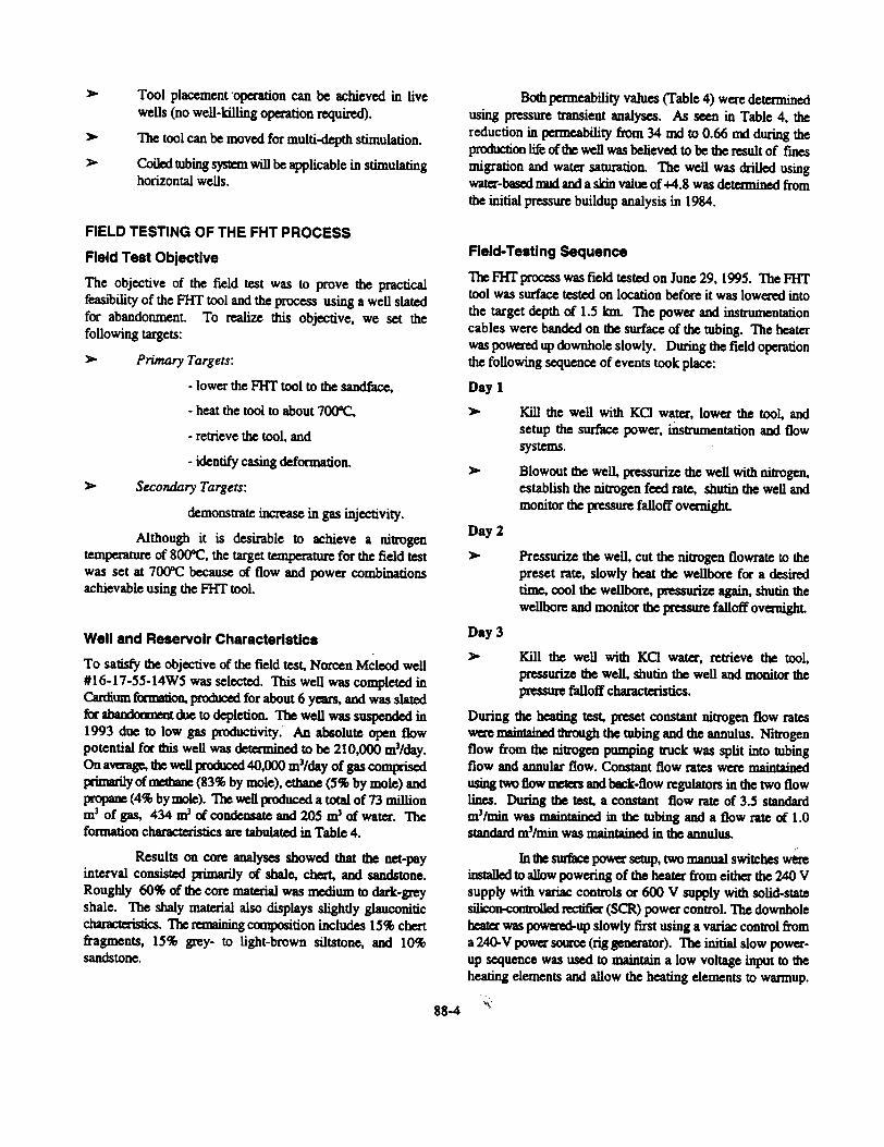
]'able 4: Reservoir. well. and nitro2en characteristics
Parameters Values
Reservoir characteristics
8.9 (measured in 1984)1.4 (measured in 1995)
1498-1503525
11%34 (determined in 1984)
0.66 (determined in 1988)+ 4.8 (determined in 1984)+ 3.4 (determined in 1988)
Initial Reservoir Pressure, MFaCurrent Reservoir Pressure, MFaFonnation Depdl, mKBReservoir Temperature, OCPay ThickI1ess, mPorosity, %Pemleability, md
Skin
Well characteristics
Wellbore radius, m 0.011
Nitrogen properties
Viscosity, mPa.s 0.021SAvg. compressibility factor O.99SGas compressibility, MPa-\ 6.24 x 1~ i- . . ,
88-11
88-12
NITROGEN TRUCK
TEMPERATUREkTUBE CONTROLLER
POWER.CONTROLLER
[==JPOWERSOURCE
l~ ~~./"':-
POWER CABLE
..- WELL HEAD
t .11\ CEMENT
METAL CASING
~/"
~
,..d-'WIRING CHAMBER
-Z- COOLING CHAMBER
m11--.8- HEATING CHAMBER
mmmmm
ZONE OFINTEREST
\7
88-13
rPERFORATION
00CD
00In
(M>I) J8MOd/(dw~) ~U8JJno
00~
(J\) 86e~IOJ\
88-14
00CO)
00N
8- 0
-II)fa0
00~
-cn0>I-~011).cO
)cO
)~
~00)O
N1-0>~
cu.";
0U')
CO
)
TTQ)
..~-fnC
Ucu",,8,
~E><
Q
)W
I-
00(f) T
0 0
&i)
0N
N
(~) eJm
eJedwel
TT
88-1S
TT
T
I
0It)--
T-cn~"~)Cw-,....
(.)i::
T
QQ-
.
T
0an
00-- 00N QInN QQCf)
0 QU') -cnQ
)-=c
0.-~
E-Q)
E.-.-
b()=.-oW~oW
"'0"'Q)
'-=Q)
oSb()='C="'0fI}~.ee~.BfI}~b()I
oW.-~
~~~~.-~
00N
U)
,.....-
0It)&
t) Q
N
Q-
-(~
) aJmeJadw
al
88-16
Qan
bO="=~4)
~-4)"=4)-=bO='C=~~~!8-e.£--4)..c~]~>
<0..c=0.=U==~Ir)~=bO
tt
EQ)
a..
~.,-
E....0)c..
Q:)Q:)C)~
88-19
cQ)E10Q)
.=10Q)~'-Q)
~
00.,-I
0Lt)I
0
0LC)
00,-