Embed Size (px)
Citation preview

AKHL1250EHIGH PRESSURE COMPRESSORCOMPRESSEUR À HAUTE PRESSIONCOMPRESOR DE ALTA PRESIÓN
OPERATING AND MAINTENANCE MANUALMANUEL D'UTILISATION ET D'ENTRETIEN
MANUAL DE OPERACIONES Y MANTENIMIENTO
BEFORE USING THIS COMPRESSOR, STUDY THIS MANUAL TO ENSURE SAFETY WARNING AND INSTRUCTIONS.KEEP THESE INSTRUCTIONS WITH THE TOOL FOR FUTURE REFERENCE.
AVANT D'UTILISER CE COMPRESSEUR, LIRE CE MANUEL ET LES CONSIGNES DE SÉCURITÉ AFIN DE GARANTIR UN FONCTIONNEMENT SÛR.CONSERVER CE MANUEL EN LIEU SÛR AVEC L'OUTIL AFIN DE POUVOIR LE CONSULTER ULTERIEUREMENT.
ANTES DE UTILIZAR ESTE COMPRESOR, LEA DETENIDAMENTE LAS INSTRUCCIONES Y ADVERTENCIAS DE SEGURIDAD.GUARDE ESTAS INSTRUCCIONES CON LA HERRAMIENTA PARA UNA POSIBLE CONSULTA FUTURA.
WARNING
AVERTISSEMENT
ADVERTENCIA

INDEX TABLE DES MATIÈRES ÍNDICEENGLISH Page 5 to 18 PageFRANÇAIS Page 19 to 32 PageESPAÑOL Page 33 to 46 Page
DEFINITIONS OF SIGNAL WORDSWARNING: Indicates a potentially hazardous situation which, if not avoided, could result in death or
serious injury.CAUTION: Indicates a potentially hazardous situation which, if not avoided, may result in minor or
moderate injury.NOTE: Emphasizes essential information.
DEFINITIONS DES INDICATEURS PRINCIPAUXAVERTISSEMENT: Indique une situation potentiellement à risque qui, si elle n’est pas évitée, peut résulter en
un danger mortel ou une blessure grave.ATTENTION: Indique une situation potentiellement à risque qui, si elle n’est pas évitée, peut résulter en
une blessure mineure ou modérée.REMARQUE: Accentue les informations essentielles.
DEFINICIÓNES DE LOS INDICADORES PRINCIPALESADVERTENCIA: Indica una situación potencialmente peligrosa que, si no se evita, puede resultar en
muerte o lesiones graves.PRECAUCIÓN: Indica una situación potencialmente peligrosa, que si no se evita, puede resultar en una
herida menor o moderada.NOTA: Destaca las informaciones esenciales.
2

3
Fig.A
Fig.B

4
Fig.C Fig.D Fig.E
Fig.F Fig.G Fig.H
Fig.I Fig.J Fig.K
Fig.L

INDEX1. SAFETY INSTRUCTIONS..................................................62. SPECIFICATIONS AND TECHNICAL DATA ..................103. INSTRUCTIONS FOR OPERATION ................................104. PROTECTIVE DEVICE.....................................................165. ABNORMALITIES DURING OPERATION.......................166. BUZZER TYPES...............................................................177. AUTOMATIC ADJUSTMENT OF OPERATING POWER
(INVERTER CONTROL)...................................................188. IN ORDER TO MAINTAIN PERFORMANCE...................18
READ ALL SAFETY WARNINGS AND ALL IN-STRUCTIONS.Failure to follow the warnings and instructions may result in death serious injury. Save all warn-ings and instructions for future reference.
RISK OF ELECTRIC SHOCKWARNING: Before doing any work on the compressor it must be disconnected from the power supply.
RISK OF HIGH TEMPERATURESCAUTION: The compressor contains some parts which might reach high temperatures.
RISK OF ACCIDENTAL START-UPCAUTION: The compressor could start automati-cally in case of a black-out and subsequent reset.
ENGLISH
OPERATING AND MAINTENANCE MANUAL
BEFORE USING THIS COMPRESSOR, STUDY THIS MANUAL TO ENSURE SAFETY WARNING AND INSTRUCTIONS.KEEP THESE INSTRUCTIONS WITH THE TOOL FOR FUTURE REFERENCE.
WARNING
5
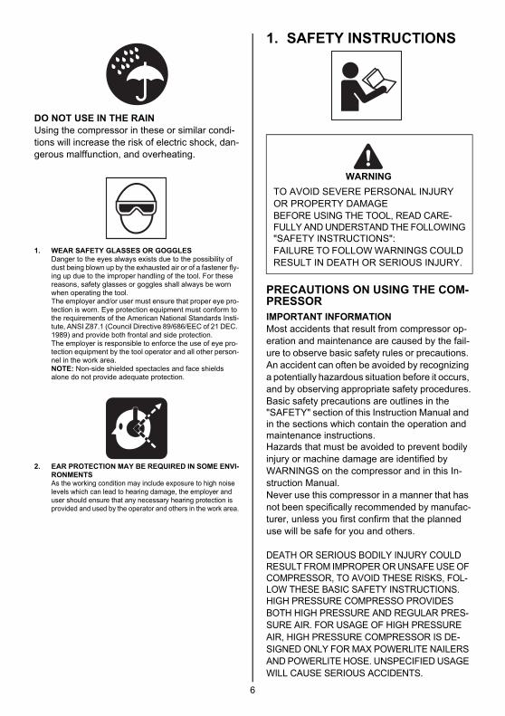
DO NOT USE IN THE RAINUsing the compressor in these or similar condi-tions will increase the risk of electric shock, dan-gerous malffunction, and overheating.
1. WEAR SAFETY GLASSES OR GOGGLESDanger to the eyes always exists due to the possibility of dust being blown up by the exhausted air or of a fastener fly-ing up due to the improper handling of the tool. For these reasons, safety glasses or goggles shall always be worn when operating the tool.The employer and/or user must ensure that proper eye pro-tection is worn. Eye protection equipment must conform to the requirements of the American National Standards Insti-tute, ANSI Z87.1 (Council Directive 89/686/EEC of 21 DEC. 1989) and provide both frontal and side protection.The employer is responsible to enforce the use of eye pro-tection equipment by the tool operator and all other person-nel in the work area.NOTE: Non-side shielded spectacles and face shields alone do not provide adequate protection.
2. EAR PROTECTION MAY BE REQUIRED IN SOME ENVI-RONMENTSAs the working condition may include exposure to high noise levels which can lead to hearing damage, the employer and user should ensure that any necessary hearing protection is provided and used by the operator and others in the work area.
1. SAFETY INSTRUCTIONS
PRECAUTIONS ON USING THE COM-PRESSORIMPORTANT INFORMATIONMost accidents that result from compressor op-eration and maintenance are caused by the fail-ure to observe basic safety rules or precautions. An accident can often be avoided by recognizing a potentially hazardous situation before it occurs, and by observing appropriate safety procedures.Basic safety precautions are outlines in the "SAFETY" section of this Instruction Manual and in the sections which contain the operation and maintenance instructions.Hazards that must be avoided to prevent bodily injury or machine damage are identified by WARNINGS on the compressor and in this In-struction Manual.Never use this compressor in a manner that has not been specifically recommended by manufac-turer, unless you first confirm that the planned use will be safe for you and others.
DEATH OR SERIOUS BODILY INJURY COULD RESULT FROM IMPROPER OR UNSAFE USE OF COMPRESSOR, TO AVOID THESE RISKS, FOL-LOW THESE BASIC SAFETY INSTRUCTIONS.HIGH PRESSURE COMPRESSO PROVIDES BOTH HIGH PRESSURE AND REGULAR PRES-SURE AIR. FOR USAGE OF HIGH PRESSURE AIR, HIGH PRESSURE COMPRESSOR IS DE-SIGNED ONLY FOR MAX POWERLITE NAILERS AND POWERLITE HOSE. UNSPECIFIED USAGE WILL CAUSE SERIOUS ACCIDENTS.
TO AVOID SEVERE PERSONAL INJURY OR PROPERTY DAMAGEBEFORE USING THE TOOL, READ CARE-FULLY AND UNDERSTAND THE FOLLOWING"SAFETY INSTRUCTIONS":FAILURE TO FOLLOW WARNINGS COULD RESULT IN DEATH OR SERIOUS INJURY.
WARNING
6

1. NEVER TOUCH MOVING PARTSNever place your hands, fingers or body parts near the compressor's moving parts.
2. NEVER OPERATE WITHOUT ALL GUARDS IN PLACENever operate the compressor without all guards or safety features in place and in proper working order. If maintenance or servicing requires the removal of a guard or safety features, be sure to replace the guards or safety feature before re-suming operation of the compressor.
3. ALWAYS WEAR EYE PROTECTIONAlways wear safety goggles or equivalent eye protection. Compressed air must never be aimed at anyone or any part of the body. Be sure to wear protective gear including the sound-proofing and protective garment, crash cap and safety foot-wear suited for the given working environment.
4. PROTECT YOURSELF AGAINST ELEC-TRIC SHOCKPrevent body contact with grounded surfac-es such as pipes, radiators, ranges and re-frigeration enclosures. Never operate the compressor in damp or wet locations.
5. DISCONNECT THE COMPRESSORAlways disconnect the compressor from the pow-er plug and remove the compressed air from the air tank before servicing, inspecting, maintaining, cleaning, replacing or checking any parts.
6. AVOID UNINTENTIONAL STARTINGDo not carry the compressor while it is con-nected to its power source or when the air tank is filled with compressed air. Be sure the knob of the pressure switch in the "OFF" position before connecting the compressor to its power source.
7. STORE COMPRESSOR PROPERLYWhen not in use, the compressor should be stored in dry place. Keep out of reach of chil-dren. Lock-out the storage area.
8. KEEP WORK AREA CLEANCluttered areas invite injuries. Clear all work ar-eas of unnecessary tools, debris, furniture, etc.
9. KEEP CHILDREN AWAYDo not let visitors contact compressor extension cord. All visitors should be kept safely away from work area. Keep out of reach of children.
10. DRESS PROPERLYDo not wear loose clothing or jewelry. They can be caught in moving parts. Wear protec-tive hair covering to contain long hair.
11. DON'T ABUSE POWER CORDNever yank it to disconnect from receptacle. Keep power cord from heat, oil and sharp edges.
12. MAINTAIN COMPRESSOR WITH CAREFollow instructions for lubricating. Inspect cords periodically and if damaged, have re-paired by authorized service facility.
13. USE A SAFE EXTENSION CORDIn order to prevent an electric shock, use a 3-core extension cord with a 3-pole earthing plug and a 3-core earthing plug socket. Make sure that the extension cord is in the good working condition. If the cord is dam-aged, replace or repair it. The cord should have a sufficient capacity for the current run-ning to the product. The cord of an insuffi-cient capacity will cause a voltage drop or an electric power loss, resulting in overheating. The following table shows the cord size used depending on the cord length.If the compressor is to be used outdoors, use an exclusive extension cord.
Tab.1 GAUGE A MAX LENGTH OF 50ft. (15m)
Avoid electrical shock hazard. Never use this compressor with a damaged or frayed electrical cord or extension cord. Inspect all electrical cords regularly. Never use in near water or in any environment where electric shock is possible.
14. STAY ALERTWatch what you are doing. Use common sense. Do not operate compressor when you are tired. Compressor should never be used by you if you are under the influence of alcohol, drugs or medication that makes you drowsy.
COMPRESSOR HP kW American Wire Gauge
AKHL1250E 2 1.5 12
WARNING
7

15. CHECK DAMAGED PARTS AND AIR LEAKBefore further use of the compressor, a guard or other part which is damaged should be carefully checked to determine that it will operate properly and perform its intended function.Check for alignment of moving parts, binding of moving parts, breakage of parts, mount-ing, air leak, and any other conditions that may affected its operation.A guard or other part that is damaged should be properly repaired or replaced by an au-thorized service facility unless otherwise in-dicated elsewhere in this Instruction Manual. Have defective pressure controllers re-placed by authorized service facility.Do not use compressor if switch does not turn it on and off.
16. OPERATE COMPRESSOR CORRECTLYOperate the compressor according to the in-structions provided herein. Never allow the compressor to be operated by children, indi-viduals unfamiliar with its operation or unau-thorized personal.
17. KEEP ALL SCREWS, BOLTS AND COV-ERS TIGHTLY IN PLACEKeep all screws, bolts, and plates tightly mounted.Check their conditions periodically.
18. KEEP MOTOR AIR VENT CLEANThe motor air vent must be kept clean so that air can freely flow at all times. Check for dust build-up frequently.
19. OPERATE COMPRESSOR AT THE RAT-ED VOLTAGEOperate the compressor at voltages speci-fied on their nameplates. If using the com-pressor at a higher voltage than the rated voltage, it will result in abnormally fast motor revolution and may damage the unit and burn out the motor.
20. NEVER USE A COMPRESSOR WHICH IS DEFECTIVE OR OPERATING ABNOR-MALLYIf the compressor appears to be operating unusually, making strange noises, or other-wise appears defective, stop using it imme-diately and arrange for repairs by an authorized service facility.
21. DO NOT WIPE PLASTIC PARTS WITH SOLVENTSolvent such as gasoline, thinner, benzine, carbon tetrachloride, and alcohol may dam-age and crack plastic parts. Do not wipe them with such solvents. Wipe plastic parts with a soft cloth lightly dampened with mild detergent and dry thoroughly.
22. USE ONLY GENUINE REPLACEMENT PARTSReplacement parts not original may void your warranty and can lead to malfunction and resulting injuries. Genuine parts are available from your dealer.
23. DO NOT MODIFY THE COMPRESSORDo not modify the compressor. Always con-tact the authorized service facility any re-pairs. Unauthorized modification may not only impair the compressor performance but may also result in accident or injury to repair personnel who do not have the required knowledge and technical expertise to per-form the repair operations correctly.
24. TURN OFF THE SWITCH WHEN THE COMPRESSOR IS NOT USEDWhen the compressor is not used, turn the switch OFF, disconnect the plug from the power source and open the drain cock to dis-charge the compressed air from the air tank.
25. NEVER TOUCH THE SURFACE OF THE HIGH-TEMPERATURE SECTIONIn order to prevent a burn, do not touch the piping, head, cylinder, motor, tank and in-verter case (lower cover).
26. DO NOT DIRECT AIR STREAM AT BODYRisk of injury, do not direct compressed air at persons or animals.
27. DRAIN TANKDrain tank daily or after 4 hours of use.
8

28. DO NOT STOP COMPRESSOR BY PULL-ING OUT THE PLUGUse the " ON/OFF " switch.
29. WHENEVER USING THE HIGH PRESSURE SIDE OF THE MAX POWERLITE COMPRES-SOR, THE GENUINE PARTS FOR THE MAX POWERLITE TOOLS, POWERLITE HOSE AND COMPRESSOR MUST BE USED.
30. NEVER USE A TRANSFORMER FOR THE POWER SUPPLY OF THIS COMPRESSOR. USING A TRANSFORMER TO INCREASE THE VOLTAGE WILL CAUSE A FAILURE OR BURNOUT. (IF A TRANSFORMER IS USED, OPERATION OF THE MACHINE WILL STOP.)
31. NEVER CONNECT THE COMPRESSOR TO AN ENGINE GENERATOR OR DI-RECT-CURRENT POWER SUPPLYThe compressor will break or be damaged from burning.
32. THIS COMPRESSOR IS FOR INDOOR USE. DO NOT INSTALL THE COMPRES-SOR IN ANY PLACE EXPOSED TO RAIN OR SPLASHED WATER, HIGH-HUMIDITY PLACE OR HIGH-TEMPERATURE PLACEIf used in the wet condition, it could produce an electric shock or be short-circuited, result-ing in ignition. Use it under the environmen-tal conditions provided by its specifications.
33. DO NOT OPERATE THE TOOL NEAR A FLAMMABLE SUBSTANCENever operate the tool near a flammable substance (e.g., thinner, gasoline, etc.). Vol-atile fumes from these substances could be drawn into the compressor and compressed together with the air and this could result in an explosion.
34. NEVER USE THE TOOL IN AN EXPLO-SIVE ATMOSPHERESparks from the tool may ignite atmospheric gases, dust or other combustible materials.
35. BE SURE TO EARTH THE COMPRESSOREarth the compressor to prevent a worker from getting an electric shock. It comes with a 3-pole cord and a 3-pole earthing plug so that it can be connected to an appropriate earthing plug socket.A green-and-yellow striped wire is an earth-ing conductor. Never connect it to other charged terminals.
36. WHEN CARRYING THE COMPRESSOR, HOLD IT CORRECTLY.
37. TAKE CARE TO TRANSPORT THE COM-PRESSOR CORRECTLY, DO NOT OVER-TURN IT OR LIFT IT WITH HOOKS OR ROPES.
38. WHEN DISPOSING THE MACHINE OR ITS PARTS, FOLLOW THE RELEVANT NA-TIONAL RULES.
39. DO NOT PUT FINGERS IN THE BLEEDER OR CLEARANCES IN THE HOUSING.This can result in injury, electric shock or burns.
40. DO NOT USE ANY ADAPTER PLUGS WITH THE COMPRESSORThe compressor is factory-equipped with a specific electric cord and plug for connection to a proper electric power source. Never modify the plug in any way. Donot use any adapter plugs with the compressor.
9
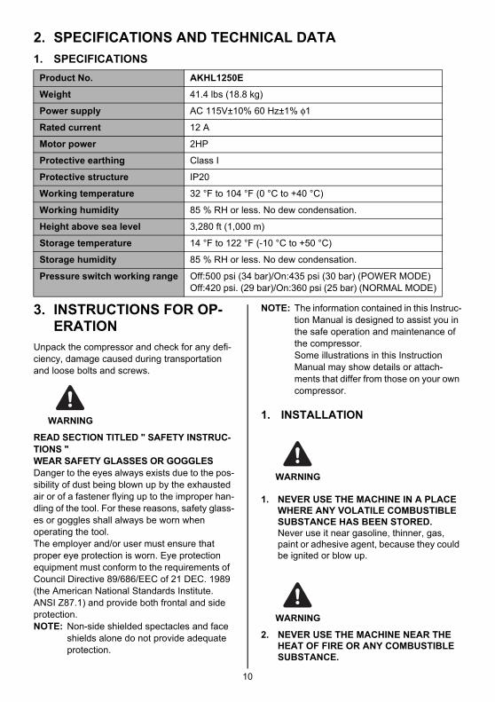
2. SPECIFICATIONS AND TECHNICAL DATA1. SPECIFICATIONS
3. INSTRUCTIONS FOR OP-ERATION
Unpack the compressor and check for any defi-ciency, damage caused during transportation and loose bolts and screws.
READ SECTION TITLED " SAFETY INSTRUC-TIONS "WEAR SAFETY GLASSES OR GOGGLESDanger to the eyes always exists due to the pos-sibility of dust being blown up by the exhausted air or of a fastener flying up to the improper han-dling of the tool. For these reasons, safety glass-es or goggles shall always be worn when operating the tool. The employer and/or user must ensure that proper eye protection is worn. Eye protection equipment must conform to the requirements of Council Directive 89/686/EEC of 21 DEC. 1989 (the American National Standards Institute. ANSI Z87.1) and provide both frontal and side protection.NOTE: Non-side shielded spectacles and face
shields alone do not provide adequate protection.
NOTE: The information contained in this Instruc-tion Manual is designed to assist you in the safe operation and maintenance of the compressor.Some illustrations in this Instruction Manual may show details or attach-ments that differ from those on your own compressor.
1. INSTALLATION
1. NEVER USE THE MACHINE IN A PLACE WHERE ANY VOLATILE COMBUSTIBLE SUBSTANCE HAS BEEN STORED.Never use it near gasoline, thinner, gas, paint or adhesive agent, because they could be ignited or blow up.
2. NEVER USE THE MACHINE NEAR THE HEAT OF FIRE OR ANY COMBUSTIBLE SUBSTANCE.
Product No. AKHL1250E
Weight 41.4 lbs (18.8 kg)
Power supply AC 115V±10% 60 Hz±1% φ1
Rated current 12 A
Motor power 2HP
Protective earthing Class I
Protective structure IP20
Working temperature 32 °F to 104 °F (0 °C to +40 °C)
Working humidity 85 % RH or less. No dew condensation.
Height above sea level 3,280 ft (1,000 m)
Storage temperature 14 °F to 122 °F (-10 °C to +50 °C)
Storage humidity 85 % RH or less. No dew condensation.
Pressure switch working range Off:500 psi (34 bar)/On:435 psi (30 bar) (POWER MODE)Off:420 psi. (29 bar)/On:360 psi (25 bar) (NORMAL MODE)
WARNING
WARNING
WARNING
10

3. NEVER USE THE MACHINE IN AN UN-STABLE PLACE.Never use it in a place where it could move or fall of itself.Be sure to install the compressor on a flat floor, with leg rubber underneath it; the al-lowable tilt angle of the floor is up to 10 de-grees. If the installation floor is tilted and slippery, ensure that the compressor does not move during operation. Do not use it on a shelf or a stand where it may fall or tumble.
4. AVOIDING A PLACE EXPOSED TO HIGH TEMPERATURE OR THE DIRECT SUN-SHINE, BE SURE TO USE THE MACHINE IN THE WELL-VENTILATED SHADE.Using it under high temperature or in the di-rect sunshine not only deteriorates its dura-bility, but increases the temperature of the main body, causing danger to your safety. Be sure to use it in the well-ventilated shade. The adequate room temperature is 41 °F to 86 °F (+5 °C to +30 °C). (32 °F to 104 °F (0 °C to +40 °C) at maximum)
5. DO NOT INSTALL THE MACHINE IN A DUSTY(WOODEN CHIPS, ETC.) PLACE.
6. INSTALL THE MACHINE IN THE APPRO-PRIATE DIRECTION.Install it appropriately.
7. NEVER INSTALL THE MACHINE IN THE RAIN OR IN A PLACE SPLASHED WITH WATER OR EXPOSED TO HIGH TEMPER-ATURE.Using it in the wet condition could cause an electric shock or a short-circuit, resulting in a fire due to burnout or ignition.
8. NEVER BLOCK A VENTILATION OPEN-ING OR USE THE MACHINE IN A BOX OR A NARROW PLACE(IN A VEHICLE, ETC.)Neglect of this may generate abnormal heat, causing a trouble or an accident.Install the compressor at the distance of 1 m or more from the wall to secure sufficient ventilation and cooling.
9. NEVER SIT OR PLACE AN OBJECT ON THE TOP OF THE MACHINE.Neglect of this could cause a trouble or break it.
Do not use the compressor in any place where the temperature is 32 °F (0 °C) or less or the ambient temperature exceeds 104 °F (+40 °C).
WARNING
WARNING
WARNING
WARNING
WARNING
WARNING
WARNING
11

2. NAME OF PARTS (See Fig.A)Description of Functions of Key Components
1 Power switch Turns on or off the power supply
2 Pressure-Reduction valve adjust-ment handle (H) (Orange cap)
Intended for exclusive use with the tool. It adjusts the operating pressure of the tool.
3 Pressure-Reduction valve adjust-ment handle (L) (Yellow cap)
Adjusts the pressure supplied to the general-purpose nailers and pneumatic tools (operating air pressure 120 psi (8.3 bar) maximum).
4 Pressure gauge in the tank Indicates pressure in the tank. The pressure increases up to 500 psi (34 bar).
5 Pressure gauge for indicating the set reduction valve pressure (2 gauges)
It indicates the set pressure on the pressure-reduction valves (H) and (L).(355 psi (24.5 bar) maximum on the H side and 120 psi(8.3 bar) maximum on the L side.)
6 High pressure air chuck (for MAX tools)
It connects the MAX air hose for the tools.
7 General-purpose air chuck (for reg-ular pressure tools)
It connects the air hose for the general-pressure nailers.Fix the General-purpose air chuck in this nipple: NPT 1/4" (for regular pressure tools). Ask your dealer or an authorized service facility to fix it.
8 Drain cock It drains compressed air and water, Drain once when the work is finished or more a day.
9 Power plug It is usable with a triode ground outlet.
0 Control panel It allows switching the mode between Normal, High Pow-er and Quiet. (See Fig.B) For details of the LEDs and switches on the Control panel, see "Control Panel" on page 13.• Current consumption is reduced in the operation in
Quiet mode.
a Air tank
b Rubber foot
c Power cord
d Grip for two-handed carry
12

Control Panel (See Fig.B)ePOWER LEDfMAINTENANCE LEDIf it is lit up, send the machine to your dealer or an authorized service facility for inspection. (See page 18)gTEMPERATURE OR ELECTRICAL PROBLEM LEDSee the buzzer types in Chapter 6. (See page 17)hSELECTOR SWITCHThe selector switch allows switching among the following operating modes.The factory default is 25-29 Normal mode.
• Before using the control panel, remove the transparent sheet covering it on the shipped machine.
iQUIET MODE SWITCHThis machine also offers a power-saving operation Quiet mode that you can select when you want to suppress the noises accompanying the operation, or when tripping of the circuit breaker is anticipated during continuous operation. Press the Quiet mode switch to turn on this mode.• A buzzer sounds with a beep and the LED lights up when the operation switching takes place.• The switching is available independent of whether the compressor is in operation or stopped.• Even when the circuit breaker tripped or you have disconnected the power plug from the outlet during
operation, status of the last operation is stored in memory.• Even when the Quiet mode switch is pressed in a low temperature environment, the compressor con-
tinues running in the Normal mode until it reaches the OFF pressure. After the compressor is fully warmed, it shifts to the Quiet mode the next time it is used.
Operating mode Pressure control range Application example
ON pressure OFF pressure
NORMAL MODE 360 psi (25 bar) 420 psi (29 bar) Joinery work by MAX tools, general-purpose nailers, etc.
HIGH POWER MODE
435 psi (30 bar) 500 psi (34 bar) Continuous surface fastening and the like with MAX tools.
13

3. MACHINE OPERATING PROCE-DURE
Inspection and checkup prior to oper-ation
• Prior to use, check the bolts and nuts for loosening and the parts for missing one.
• The power supply used must AC 115V 15 A and provided with a circuit breaker. Allow-able source voltage range is +/-10%.
• Gauge and length of the extension cord or drum cord used must be AWG 12 minimum and 50 ft. (15m) maximum, respectively. And the cord must be fully drawn out when used.
• Make sure the machine is installed in the right direction when using it.
∗ Use the machine in compliance with the in-structions provided in "SAFTY INSTRUC-TIONS" on page 6.
∗ Pressure values in the description do not in-clude the error in reading the pressure gauge.
1. After turning off the machine power switch, connect the power plug to the outlet. • When using an extension cord or drum
cord, make sure its effective gauge and length are AWG 12minimum and 50 ft. (15m) maximum, respectively.
2. (Fig.C,D) Turn the power switch on while maintaining the drain cock fully open. The buzzer sounds with a beep at the same time.• For buzzer sounding patterns, see
page 17.
3. Make sure that the motor starts to run and the air is leaking from the drain cock when the drain cock is open.
4. (Fig.E) Close the drain cock and make sure no air is leaking from the cock.
5. Turn the adjustment handle (in 2 loca-tions) of the pressure-reduction valve ful-ly clockwise until you cannot move it anymore and make sure that the above operation moves the pressure gauge pointer (Fig.F) at both locations.
• As the pressure in the air tank increases due to the pressure characteristic of the pressure-reduction valve, the pressure can vary from the set supply pressure by as much as 29 psi (2 bar).Turn the pressure-reduction valve's adjust-ment handle counterclockwise once to re-duce the pressure and then proceed to the adjustment while increasing the pressure by turning the adjusting hand clockwise.
6. Make sure that the compression opera-tion is automatically stopped in 6 to 7 minutes. Except when the power-saving operation in Quiet mode is turned on, auxiliary tank is connected or voltage drop occurred, since these extends the operating hours.
7. Wait for 5 minutes after the operation is stopped to confirm that there are no ab-normal noises or air leakages and that the compressor does not restart.
8. (Fig.D) Discharge the compressed air by opening the drain cock somewhat. Make sure that the operation is resumed due to a decrease in the pressure.
9. (Fig.E,G) Close the drain cock and turn the power off while the compression op-eration is turned on to make sure that these actions stop the machine from op-erating.
10. (Fig.H) Turn the adjustment handle (in 2 locations) of the pressure-reduction valve counterclockwise to make sure that this turning moves the pressure gauge pointer downward at both locations. (You may hear sounds due to air leaking but it does not mean there is a failure.)
WARNINGCAUTION
14

11. (Fig.D) Open the drain cock to discharge all the compressed air and water in the air tank.If you found any abnormalities in the check-up or inspection prior to the operation, send the machine to your dealer or authorized service facility for inspection or repair.
Operating ProcedureBefore operating the machine, be sure to carry out the "Inspection and checkup prior to opera-tion" described on page 14.
1. Fully open the drain cock and turn the power switch on. The buzzer will sound with a beep at the same time.• For buzzer sounding patterns, see
page 17.After the operation has started, close the drain cock tight to increase the pressure.
2. (Fig.I) After confirming the operation has stopped due to the increased pressure, turn the adjustment handle of the pres-sure-reduction valve to adjust the operat-ing pressure of the nailer and pneumatic tool to the appropriate level. When ad-justing the pressure, turn the pressure-reduction valve's adjustment handle counterclockwise to set the pressure at a level lower than the appropriate value by 2 bars once. Then proceed to the adjust-ment while increasing the pressure by turning the handle clockwise.• Make sure to start the adjustment at a level
lower than the appropriate pressure and continue the adjustment while increasing the pressure from that level upward. If you start the adjustment from a level higher than the appropriate value, an error results between the pressure gauge value and ac-tually used pressure. (Due to Characteris-tics of pressure-reduction valve respectively)
• 2 pressure-reduction valves provided on this machine allow you to connect MAX
and the general-purpose nailer or pneumatic tool.<Pressure-reduction valve H> Allows connection and use of MAX PowerLite tools (of operating pressure of 355 psi (24.5 bar) maximum)<Pressure-reduction valve L> Allows con-nection and use of the general-purpose nailers or pneumatic tools (of operating pressure of 120 psi (8.3 bar) maximum)
• You must observe the specified operating air pressure for the nailers and pneumatic tools.Using a nailer or pneumatic tool without ad-justing the supply pressure with the reduc-tion valve can seriously degrade their performance, induce their premature aging or damage them.
• Using a nailer or pneumatic tool at an inappro-priate pressure level (at an unnecessary high pressure) increases their air consumption, po-tentially degrading their capability in continu-ous work. Be sure to use them at the appropriate pressure.
3. (Fig.J) After you have finished with the adjustment of supply pressure, you can start the operation by connecting the air hose to the air outlet (air chuck).
4. Connect the high pressure hose to the high pressure air hose for MAX PowerLite tools to the high pressure air chuck on the H side of the pressure-reduction valve.Connect the air hose for the general-purpose nailer to the air chuck on the L side of the pressure-reduction valve.• The air chuck is the one-touch type, allow-
ing you to connect the air plug to the air chuck just by pushing in.
• Before connecting the air hose to this com-pressor, make sure that the air hose and hose fixture are firmly secured.
5. OPERATION MODEOperation mode switching on this machine is carried out by the selector switch. Select a desired mode from those listed in the table on page 13 according to the given applica-tion.
WARNING
WARNING
15

4. PROTECTIVE DEVICEIf internal heat builds up during operation due to clogging of the airflow orifice, if the machine is used in a highly heated environment or if an ab-normality occurs inside the machine, the thermal protector for preventing burnout may be activat-ed to stop the motor operation. The buzzer will sound in this case. In such a case:
1. (Fig.G,K) Turn the power switch off and disconnect the power plug from the out-let.• For buzzer sounding patterns, see
page 17.
2. (Fig.C,L) Connect the power plug to the outlet and turn the power switch on to resume the operation.• If the motor has sufficiently cooled down,
the resumed operation may active the pro-tective device soon after. In other cases, the operation may not resumed when you turned the power switch on. In such a case, wait for about 30 minutes for the mo-tor to cool down before restarting the ma-chine.
3. If the protective device was activated when there were no apparent problems existing in the operating environment, stop using the compressor and send it to your dealer or authorized service facility for checkups or repairs.
5. ABNORMALITIES DURING OPERATION
• If you detect any abnormalities, do not op-erate the compressor.
If you encounter any of the following abnormal phenomena, turn off the power switch immedi-ately, disconnect the power plug from the outlet and send the machine to your dealer or author-ized service facility for checkups or repairs.
1. The following problems may occur even when there are no problems with the power supply or wiring: (See "PROTEC-TIVE DEVICE" on page 16.)• Turning on the power switch does not start
up the machine.• Motor vibration is generated
2. Abnormal sounds are generated during operation. (See "AUTOMATIC ADJUST-MENT OF OPERATING POWER" (IN-VERTER CONTROL) on page 18.)
3. The safety valve instead of the pressure sensor is activated, allowing the com-pressed air to blow out.
4. Air leakage happens.5. Pressure does not increase. (See
page 18)6. An electrical shock-like pain is felt when
touched the metal part.7. Other abnormalities than the above that
is recognized during operation.
WARNING
WARNING
16

6. BUZZER TYPES
In normal operation
In cases of abnormal operation
i) If an excessively low voltage state (80 V or below) is continued for 4 seconds or longer, LED re-mains lighting up even after the voltage has been recovered.
ii) If the voltage drops down to a low voltage level of 65 V or below, LED remains lighting up with short beep sounds (Pi, Pi, Pi, ...), until power switch is turned off.If the voltage drops down further and motor stops with error, LED also remains lighting up with short beep sounds (Pi, Pi, Pi, ...), until power switch is turned off.
iii) If an excessively high voltage state (155 V or over) is continued for 2 seconds or longer, LED lights up without beep sounds. LED is turned off after the voltage drops down under 155 V.
iv) If the voltage increases to a high voltage level of 165 V or over for 2 seconds or longer, motor stops automatically and LED remains lighting up with long beep sounds (Piii ........), until power switch is turned off.
v) In other cases of abnormal motor stop automatically, LED remains lighting up with intermittent long beep sounds (Pi, Pi, Pi, ...), until power switch is turned off.
Buzzer sounds Symptom Actions taken
A one-time short beep sound (Pi)At powering on -
When the operating mode is switched -
Buzzer soundsTEMPERATURE OR ELECTRICAL PROB-LEM LED ( LED)
Cause Actions taken
1
None
Lighting up Voltage is too low or high
Examine the state of the power supply (See page 18)
Short beep sounds (Pi, Pi, Pi, ...) * refer to the below i)~iv)
2
Long beep sounds (Pii, Pii, Pii, ...)
Lighting up
• Motor temperature went abnormally high
• Temperature in the control circuit has built up to an abnormally high level(LED remains lighting up.)
• Do not use the com-pressor in extremely high temperatures.
• Do not clog the airflow orifice.
• Examine the state of the power supply(See page 18)
• Do not use the com-pressor in a place where it can be splashed with water or in a highly humid place.
3
Short beep beep-ing sounds (Pi, Pi, Pi, ...) * refer to the below v)
Blinking
• Motor does not run• Failure in the control
circuit(LED remains blinking.)
It is due to a failure on the inverter or motor. Send the machine to your deal-er or authorized service facility to have their checkup or repair.
17

7. AUTOMATIC ADJUSTMENT OF OPERATING POWER (IN-VERTER CONTROL)
Microcomputer-based inverter control is enabled on this machine in order to ensure the maximum utilization of the discharging performance. Ad-justment of the operating power is automatically continued until the pressure in the machine tank reaches the maximum level being set for the cur-rently set mode. Operating sounds may change when the operating power is switched, but you do not have to worry about them. Changes in the sounds are not due to a failure.
• The pressure level at which the output change-over is activated varies depending on the ca-pacity of the main power supply, type of extension cord used and parallel use of other electric equipment. If the voltage is excessively low, extra time will be required for the filling.
• If the fill time is longer than usual or when the pressure does not increase, change the cur-rent connection to the power supply (reconnect to the main power supply) or stop the joint use of the power supply with a power tool.
• When capacity of the main power is AC 115V or less, or when it is jointly used with another power tool, a radical voltage drop results, in-ducing startup failure.
• The circuit breaker of the power supply may be activated if the total current consumption re-sulting from the parallel use with another pow-er tool exceeds the current capacity of the circuit breaker.If the circuit breaker trips, the power supply switch of the compressor moves to the OFF position.Stop using other power tools on the same pow-er source as the compressor or stop using an extension cord and connect the compressor di-rectly to the power source. Then, after waiting for 30 seconds or more, turn the switch ON.
8. IN ORDER TO MAINTAIN PERFORMANCE
1. Drain water from the machine.After the work is finished, turn the handle of the pressure-reduction valve clockwise and open the drain cock gradually to drain the compressed air and water in the air tank until the pressure gauge pointer of the pressure-reduction valve points to 0. • Not draining the water will result in the
inside of the air tank becoming moldy, potentially leading to a failure.
2. (Fig.B17) The Maintenance LED lights up or flashes.Operating hours of this machine are meas-ured with a microcomputer. The MAINTE-NANCE LED lights up as the machine operating hours reaches 1000 hours. If the Maintenance LED lights up, send the ma-chine to your dealer or an authorized service facility for inspection.
3. Implement the machine inspection on a regular basis.The User is requested to implement cleaning and inspection of the machine in order to maintain its performance. Please do not hes-itate to let your dealer or authorized service facility inspect your machine.
4. Handle this machine carefully.Dropping the machine inadvertently, bump-ing it against solid objects or hitting it can cause deformation, cracks or damage to the machine. The User is advised not to invite an accident by dropping, bumping or hitting the machine.
5. Inspect the machine every time you use it.Check and inspect the machine in conform-ance with the procedure described in the SAFETY INSTRUCTIONS provided on page 6 and after.
6. ABOUT PRODUCTION YEARThis product bears production number in the RATING LABEL. The two digits of the number from left indicates the production year.
(Example)08826035D
Year 2008
18

• The content of this manual might be changed without notice for improvement.• Le contenu de ce manuel est sujet à modification sans préavis à des fins d'amélioration.• El contenido de este manual se puede modificar sin previo aviso para su mejora.
• The specifications and design of the products in this manual will be subject to change without advance notice due to our continuous efforts to improve the quality of our products.
• Les caractéristiques et la conception des produits mentionnés dans ce manuel sont sujettes à des modifications sans préavis en raison de nos efforts continus pour améliorer la qualité de nos produits.
• Las especificaciones y el diseño de los productos de este manual estarán sujetos a modificación sin previo aviso debido a nuestros continuos esfuerzos para mejorar la calidad de nuestros productos.
4010262121004-00/00
PRINTED IN JAPAN IMPRIMÉ AU JAPON IMPRESO EN JAPÓN
257 East 2nd StreetMineola, NY 11501, U.S.A.TEL: 1-800-223-4293FAX: (516)741-3272
www.maxusacorp.com (USA Site)wis.max-ltd.co.jp/int/ (GLOBAL Site)