Embed Size (px)
Citation preview
ARAL SEA BASIN PROGRAM WATER & ENVIRONMENTAL MANAGEMENT
PROJECT
COMPONENT C: DAM SAFETY AND RESERVOIR MANAGEMENT
AKHANGARAN DAM
SAFETY ASSESSMENT REPORT
March 2000
In association with
Akhang Master Issue 1.0 / Issue Date
AKHANGARAN DAM SAFETY ASSESSMENT REPORT
CONTENTS
Chapter Description Page
1 INTRODUCTION 1-1
1.1 Background to Project 1-1
1.2 Safety Assessment Procedures 1-2
1.3 Scope of Safety Assessment 1-2
2 PRINCIPAL FEATURES AND DIMENSIONS OF THE DAM 2-1
2.1 Location, Purpose and date of Construction 2-1
2.2 Description of the Dam 2-1
2.3 Hazard Assessment 2-2
3 DESIGN CONSIDERATIONS 3-1
3.1 Hydrology 3-1
3.2 Geology and Seismicity 3-1
3.3 Construction Materials and their Properties 3-2
3.4 Seepage Control Measures 3-2
3.5 Reservoir Draw-off Works 3-3
3.6 Performance Monitoring Instrumentation 3-3
3.7 Hydropower Facilities 3-4
4 DAM CONDITION AND PERFORMANCE 4-1
4.1 Comments Arising out of Inspection 4-1
4.2 Assessment of Performance Monitoring Results 4-1
4.3 Dam Safety Incidents 4-2
4.4 Maintenance Procedures and Standards 4-2
4.5 Existing Early Warning & Emergency Procedures 4-2

Akhang Master Issue 1.0 / Issue Date
5 SAFETY ASSESSMENT 5-1
5.1 General 5-1
5.2 Structural Safety 5-1
5.3 Safety against Floods 5-2 5.3.1 Discussion on the exceedance probability of design hydrographs 5-2 5.3.2 Factors which reduce the dam safety during floods 5-3 5.3.3 Conclusions and recommendations 5-4
5.4 Provision for Emergency Draw-down 5-4
5.5 Safety against Earthquakes 5-5 5.5.1 Seismic design criteria 5-5 5.5.2 Liquefaction and fill and foundation materials 5-5
5.6 Other Safety Matters 5-6 5.6.1 Upper Turksky landslip 5-6 5.6.2 Naugarzan dam 5-6 5.6.3 Security of access 5-7 5.6.4 Security of electric power supply 5-7
5.7 Safety Assessment - Summary 5-7 5.7.1 Principal matters of concern 5-7 5.7.2 Safety Statement 5-7
6 RECOMMENDED STUDIES, WORKS AND SUPPLIES 6-1
6.1 General 6-1
6.2 Additional Surveys, Investigations, Inspections and Studies 6-1 6.2.1 General 6-1 6.2.2 Surveys 6-1 6.2.3 Ground Investigations and Inspections 6-2 6.2.4 Engineering Studies 6-2
6.3 Construction Works 6-3
6.4 Equipment and Supplies 6-5
6.5 Emergency Planning Studies 6-5
6.6 Safety Measures-Priorities 6-5
7 CONCLUSIONS 7-1 REFERENCES APPENDIX A List of Data Examine APPENDIX B Hazard Assessment Procedure APPENDIX C Report by Instrumentation Specialist DRAWINGS 1. Akhangaran dam location plan
2. Dam layout 3. Embankment layout 4. Geological profile through the dam

Akhang Master Issue 1.0 / Issue Date
5. Typical cross section 6. Longitudinal section through the tunnel 7. Naugrzan dam instake structure
UNITS AND ABBREVIATIONS ASBP Aral Sea Basin Program CA Central Asia CMU Component Management Unit EA/EIA Environmental Assessment/Environmental Impact Assessment EC-IFAS Executive Committee of IFAS FSL Full Storage Level FSU Former Soviet Union FAO/CP Food and Agriculture Organisation/World Bank Co-operative Programme GDP Gross Domestic Product GEF Global Environment Facility ICB International Competitive Bidding ICOLD International Commission on Large Dams ICWC Interstate Commission for Water Coordination IDA International Development Association of the World Bank IFAS International Fund to Save the Aral Sea JSC Joint Stock Company LDL Lowest Drawdown Level M & E Monitoring and Evaluation NCB National Competitive Bidding NGO Non-governmental Organisation O & M Operation and Maintenance PIP Project Implementation Plan PIU Project Implementation Unit PMCU Project Management and Coordination Unit PMF Probable Maximum Flood RE Resident Engineer TA Technical Assistance TOR Terms of Reference SIC Scientific Information Centre (of the ICWC) SU Soviet Union SW Small Works VAT Value Added Tax WARMAP Water Resource Management and Agricultural Production in CA Republics masl metres above sea level Mm3 million cubic metres km3 cubic kilometres = 1000 Mm3 m3/s cubic metres per second ha hectare hr hour
Akhang Master 1-1 Issue 1.0 / Issue Date
1 INTRODUCTION
This report is one of ten reports prepared under Component C: Dam and Reservoir Management, of the Water and Environmental Management Project (WAEMP). The WAEMP is supported by a variety of donors, such as the Global Environment Facility (GEF) via the World Bank, the Dutch and Swedish Governments and the European Union, and is being implemented by the IFAS Agency for the GEF Project under the Aral Sea Basin Program.
1.1 Background to Project
In general, the WAEMP aims at addressing the root causes of overuse and degradation of the international waters of the Aral Sea Basin, and to start reducing water consumption, particularly in irrigation. The project also aims to pave the way for increased investment in the water sector by the public and private sectors as well as donors. The project addresses this aim in several components. Dam and Reservoir Management, the assignment with which this report is concerned, is one of them. The other components are: Water and Salt Management, the leading component, to prepare common policy, strategy and action programs; Public Awareness to educate the public to conserve water; Transboundary Water Monitoring to create the capacity to monitor transboundary water flows and quality; Wetlands Restoration to rehabilitate a wetland near the Amu Darya delta; and Project Management. The components have close links with each other. The Dam and Reservoir Management Component focuses on four activities as follows: a) Continuing an independent dam safety assessment in the region, improve dam
safety, address sedimentation and prepare investment plans; b) Upgrading of monitoring and warning systems at selected dam sites on a pilot
basis; c) Preparing detailed design studies for priority dam rehabilitation measures; and d) Gathering priority data and preparation of a program for Lake Sarez. The activities are grouped for work process purposes into two packages and will be executed simultaneously, according to an agreed schedule of works: Dam safety and reservoir management (including activities “a”, “b” and “c”); Lake Sarez safety assessment (covering activity “d”).
The Dam Safety and Reservoir Management package covers the following areas: dam safety, natural obstructions, silting of reservoirs, control of river channels etc. The activity covers the following 10 dams, two in each country: Kazakhstan: Chardara and Bugun dams; Kyrgyzstan: Uchkurgan and Toktogul dams; Tajikistan: Kayrakkum and Nurek dams; Turkmenistan: Kopetdag and Khauzkhan dams; and Uzbekistan: Akhangaran and Chimkurgan dams. Because of the need to safeguard human life, early priority is being given to safety reviews at each of the dams, which is the subject of this report.
Akhang Master 1-2 Issue 1.0 / Issue Date
1.2 Safety Assessment Procedures
The dam safety assessments are the first stage in the evaluation (including costing and economic justification) analysis, design and implementation of measures aimed at ensuring safe operation of the selected dams. They have been prepared based on a brief reconnaissance visit to each dam, discussions with the operating staff and a perusal of such information and data as was found to be readily available (see Appendix A). A data collection and cataloguing procedure was initiated before commencement of the assignment but this process (to be carried out by National Teams) is still at an early stage in implementation. The field visits were made and the reports prepared by a team of international experts specialising in dam engineering and dam safety procedures. The team comprises experts from GIBB Ltd (United Kingdom) and its associate for this assignment, Snowy Mountains Engineering Corporation (SMEC) from Australia, together with members of a team of regional experts who have been contracted as individuals to work with the Consultants for this project. This team is referred to here as the International Consultants (IC). The International Consultants have been supported during the field visits by members of National Teams appointed for this project from each of the five Central Asian republics. The principal members of the international team, who are the authors of this report, are the following: - Jim Halcro-Johnston (GIBB Ltd) – Team Leader Gennady Sergeyevich Tsurikov (Uzbekistan) – deputy Team Leader Edward Jackson (GIBB Ltd) – Dam Engineering Specialist Ljiljana Spasic-Gril (GIBB Ltd) – Geotechnical Engineer/Dam Structures Specialist Pavel Kozarovski (SMEC) – Hydrologist/Hydraulic Engineer E.V. Gysyn – Dams Specialist (Kazakhstan) E.A . Arapov – Hydraulic Structures Specialist (Turkmenistan) G.T . Kasymova – Energy Expert (Kyrgyz Republic) R. Kayumov – Hydrostructures Specialist (Tajikistan) R.G. Vafin – Hydrologist, specialising in reservoir silting (Uzbekistan) V.N. Pulyavin – Dam Instrumentation Specialist (Uzbekistan) N.A. Buslov – Dam Specialist (Turkmenistan) Y.P. Mityulov – Cost and Procurement Expert (Uzbekistan) N. Dubonosov – Mechanical Equipment Expert (Kyrgyz Republic)
Most of the above team members have contributed in the preparation of this report.
1.3 Scope of Safety Assessment
The safety assessments are made based on superficial evidence observed during the site visits, discussions with operating staff and subsequent discussions with members of the National Teams and an examination of supporting design and construction documents as has been made available to the IC for review. (A full list of the documents reviewed is included as Appendix A )

Akhang Master 1-3 Issue 1.0 / Issue Date
The safety evaluation of the dam has required an assessment of the following factors: 1. The characteristics of the reservoir and dam site, which includes the flood
regime for the river, and the geological conditions at the site; 2. The characteristics of the dam, covering its design and present condition; 3. The expected standards of operation and maintenance of the dams ,its
performance, and the implications for safety; 4. The effects on the downstream area resulting from a failure of the dam or an
excessive release of water. The structure of this report reflects the scope of safety assessment. Chapter 2 presents a general description of the dam, including location, purpose, principal dimensions and assessment of its hazard rating in relation to the impact that a safety incident would have on the adjacent community. Chapter 3 discusses the design factors that principally affect the safety of the dam. Comments on the condition and performance of the dam are given in Chapter 4 and in Chapter 5 an assessment of its safety is given. Chapter 6 gives recommendations for studies, works and supplies to be undertaken in the interests of ensuring the safety of the dam and the downstream community. Conclusions and recommendations are summarised in Chapter 7. The recommendations for safety measures given in this report must be regarded as tentative as their precise scope will depend on the outcome of further studies which are outside the scope of the present assignment. No attempts has therefore been made at this stage to evaluate the cost of the required remedial works or to carry out an economic justification for the works proposed, which will be necessary to support an application for funding. This will be carried out when the necessary studies and detail designs have been completed.
Akhang Master 2-1 Issue 1.0 / Issue Date
2 PRINCIPAL FEATURES AND DIMENSIONS OF THE DAM
2.1 Location, Purpose and date of Construction
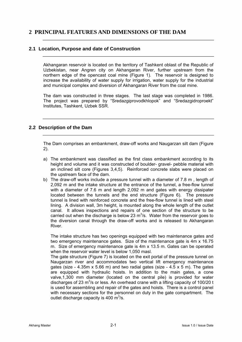
Akhangaran reservoir is located on the territory of Tashkent oblast of the Republic of Uzbekistan, near Angren city on Akhangaran River, further upstream from the northern edge of the opencast coal mine (Figure 1). The reservoir is designed to increase the availability of water supply for irrigation, water supply for the industrial and municipal complex and diversion of Akhangaran River from the coal mine. The dam was constructed in three stages. The last stage was completed in 1986. The project was prepared by “Sredazgiprovodkhlopok” and “Sredazgidroproekt” Institutes, Tashkent, Uzbek SSR.
2.2 Description of the Dam
The Dam comprises an embankment, draw-off works and Naugarzan silt dam (Figure 2). a) The embankment was classified as the first class embankment according to its
height and volume and it was constructed of boulder- gravel- pebble material with an inclined silt core (Figures 3,4,5). Reinforced concrete slabs were placed on the upstream face of the dam.
b) The draw-off works include a pressure tunnel with a diameter of 7.8 m , length of 2,092 m and the intake structure at the entrance of the tunnel, a free-flow tunnel with a diameter of 7.6 m and length 2,092 m and gates with energy dissipater located between the tunnels and the end structure (Figure 6). The pressure tunnel is lined with reinforced concrete and the free-flow tunnel is lined with steel lining. A division wall, 3m height, is mounted along the whole length of the outlet canal. It allows inspections and repairs of one section of the structure to be carried out when the discharge is below 23 m3/s. Water from the reservoir goes to the diversion canal through the draw-off works and is released to Akhangaran River. The intake structure has two openings equipped with two maintenance gates and two emergency maintenance gates. Size of the maintenance gate is 4m x 16.75 m. Size of emergency maintenance gate is 4m x 13.5 m. Gates can be operated when the reservoir water level is below 1,050 masl. The gate structure (Figure 7) is located on the exit portal of the pressure tunnel on Naugarzan river and accommodates two vertical lift emergency maintenance gates (size - 4.35m x 5.66 m) and two radial gates (size - 4.5 x 5 m). The gates are equipped with hydraulic hoists. In addition to the main gates, a cone valve,1,300 mm diameter (located on the central pile) is provided for water discharges of 23 m3/s or less. An overhead crane with a lifting capacity of 100/20 t is used for assembling and repair of the gates and hoists. There is a control panel with necessary sections for the personnel on duty in the gate compartment. The outlet discharge capacity is 400 m3/s.

Akhang Master 2-2 Issue 1.0 / Issue Date
c) Naugarzan dam is constructed on Naugarzan river and is located between the pressure and free-flow tunnels. The dam has a storage capacity of 4.0 Mm3 and is designed for regulation of Naugarzan river floods. At 0.01% flood a maximum discharge is 400 m3/s and the run-off is 2.52 Mm3. Naugarzan dam includes an embankment and draw-off works. The embankment is 33m high and was constructed of sandy pebble. The draw-off works include an intake tower and free-flow concrete diversion culvert. The tower has a diameter of 8 m, two rows of openings (size 1.2m x 1.5m) and a trash- rack on its top. The culvert is 150m long and is 2.5m x 3.5m in cross section. It is designed for a discharge of 60 m3/s.
2.3 Hazard Assessment
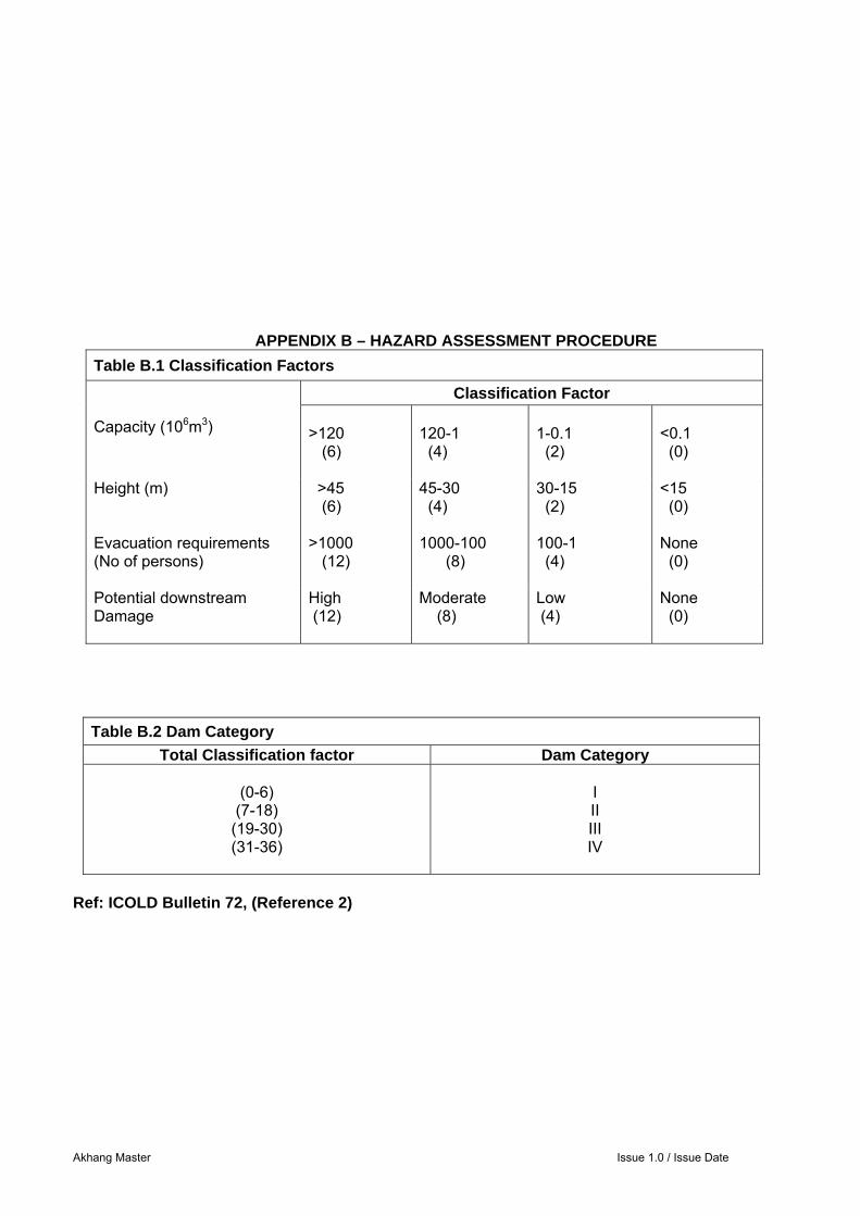
In many countries a formal classification system is used to define the risk a dam represents, in terms of the potential for loss of life and/or damage to property which could result in the event of flooding caused by failure of the dam or an extensive release of water. The magnitude of the risk depends partly on the characteristics of the dam and reservoir and partly on the conditions downstream of the dam. Risk factors based on the procedure set out in ICOLD Bulletin 72 (Reference 1) are shown in Tables B1 and B2 in Appendix B. Based on the tables in Appendix B, the total risk factor of 28 points (Table 2.2) puts the Akhangaran dam in Risk Class IIII, which is the second highest risk category. Table 2.2 Akhangaran Dam – Risk Factor
Points
Reservoir Capacity (Mm3) 260 6
Dam Height (m) 100 6
Downstream Evacuation Requirements
1 - 100
4
Potential Damage Downstream High 12
TOTAL 28 The dam is in a unique situation, in that, being just upstream of the very large excavation for the Akhangaran opencast coal mine, the latter would, in effect, act as a repository for the impounded water in the event of a breach. In Table 2.2, the comparatively small number listed under ‘downstream evacuation requirements’ reflects the fact that only the small number of workers in the coal mine would be directly impacted by a breach.
Akhang Master 2-3 Issue 1.0 / Issue Date
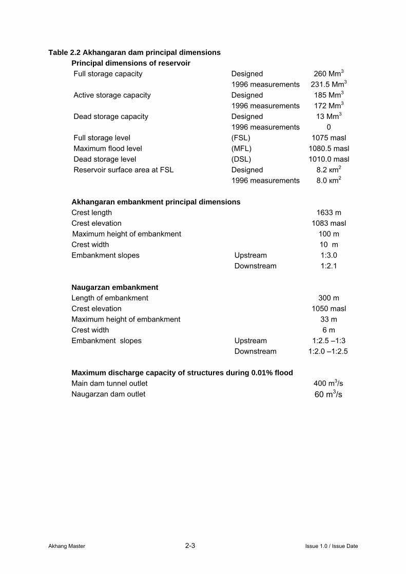
Table 2.2 Akhangaran dam principal dimensions Principal dimensions of reservoir Full storage capacity Designed 260 Mm3 1996 measurements 231.5 Mm3 Active storage capacity Designed 185 Mm3 1996 measurements 172 Mm3 Dead storage capacity Designed 13 Mm3 1996 measurements 0 Full storage level (FSL) 1075 masl Maximum flood level (MFL) 1080.5 masl Dead storage level (DSL) 1010.0 masl Reservoir surface area at FSL Designed 8.2 кm2 1996 measurements 8.0 кm2 Akhangaran embankment principal dimensions Crest length 1633 m Crest elevation 1083 masl
Maximum height of embankment 100 m Crest width 10 m Embankment slopes Upstream 1:3.0 Downstream 1:2.1 Naugarzan embankment Length of embankment 300 m Crest elevation 1050 masl Maximum height of embankment 33 m Crest width 6 m Embankment slopes Upstream 1:2.5 –1:3 Downstream 1:2.0 –1:2.5 Maximum discharge capacity of structures during 0.01% flood Main dam tunnel outlet 400 m3/s Naugarzan dam outlet 60 m3/s
Akhang Master 3-1 Issue 1.0 / Issue Date
3 DESIGN CONSIDERATIONS
3.1 Hydrology
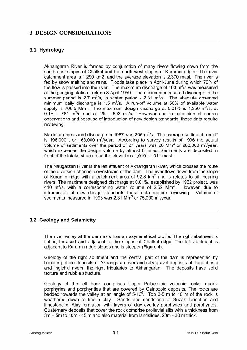
Akhangaran River is formed by conjunction of many rivers flowing down from the south east slopes of Chatkal and the north west slopes of Kuramin ridges. The river catchment area is 1,290 km2, and the average elevation is 2,370 masl. The river is fed by snow melting and rains. Floods take place in April-June during which 70% of the flow is passed into the river. The maximum discharge of 460 m3/s was measured at the gauging station Turk on 8 April 1959. The minimum measured discharge in the summer period is 2.7 m3/s, in winter period - 2.31 m3/s. The absolute observed minimum daily discharge is 1.5 m3/s. A run-off volume at 50% of available water supply is 706.5 Mm3. The maximum design discharge at 0.01% is 1,350 m3/s, at 0.1% - 764 m3/s and at 1% - 503 m3/s. However due to extension of certain observations and because of introduction of new design standards, these data require reviewing. Maximum measured discharge in 1987 was 306 m3/s. The average sediment run-off is 196,000 t or 163,000 m3/year. According to survey results of 1996 the actual volume of sediments over the period of 27 years was 26 Mm3 or 963,000 m3/year, which exceeded the design volume by almost 6 times. Sediments are deposited in front of the intake structure at the elevations 1,010 –1,011 masl. The Naugarzan River is the left effluent of Akhangaran River, which crosses the route of the diversion channel downstream of the dam. The river flows down from the slope of Kuramin ridge with a catchment area of 92.8 km2 and is relates to silt bearing rivers. The maximum designed discharge at 0.01%, established by 1962 project, was 440 m3/s, with a corresponding water volume of 2.52 Mm3. However, due to introduction of new design standards these data require reviewing. Volume of sediments measured in 1993 was 2.31 Mm3 or 75,000 m3/year.
3.2 Geology and Seismicity
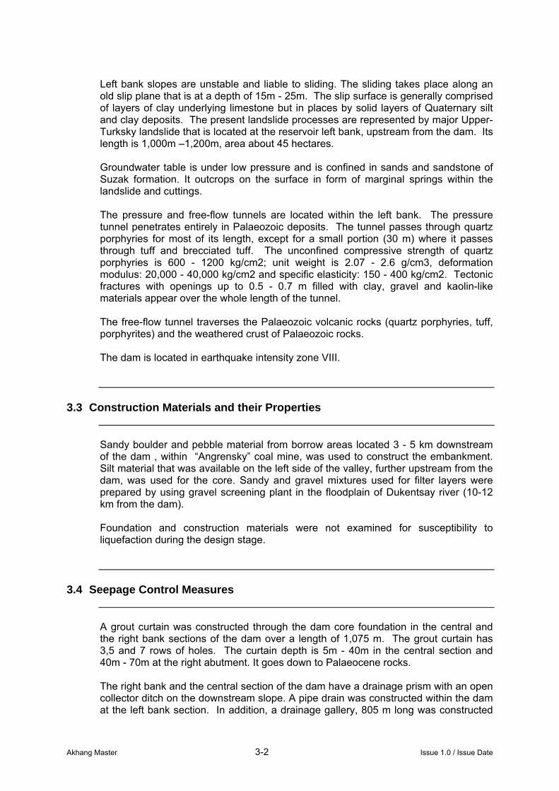
The river valley at the dam axis has an asymmetrical profile. The right abutment is flatter, terraced and adjacent to the slopes of Chatkal ridge. The left abutment is adjacent to Kuramin ridge slopes and is steeper (Figure 4). Geology of the right abutment and the central part of the dam is represented by boulder pebble deposits of Akhangaran river and silty gravel deposits of Tuganbashi and Ingichki rivers, the right tributaries to Akhangaran. The deposits have solid texture and rubble structure. Geology of the left bank comprises Upper Palaeozoic volcanic rocks: quartz porphyries and porphyrities that are covered by Cainozoic deposits. The rocks are bedded towards the valley at an angle of 5-130. Top 3-5 m to 10 m of the rock is weathered down to kaolin clay. Sands and sandstone of Suzak formation and limestone of Alay formation with layers of clay overlay porphyries and porphyrites. Quaternary deposits that cover the rock comprise prolluvial silts with a thickness from 3m – 5m to 10m - 45 m and also material from landslides, 20m - 30 m thick.
Akhang Master 3-2 Issue 1.0 / Issue Date
Left bank slopes are unstable and liable to sliding. The sliding takes place along an old slip plane that is at a depth of 15m - 25m. The slip surface is generally comprised of layers of clay underlying limestone but in places by solid layers of Quaternary silt and clay deposits. The present landslide processes are represented by major Upper-Turksky landslide that is located at the reservoir left bank, upstream from the dam. Its length is 1,000m –1,200m, area about 45 hectares. Groundwater table is under low pressure and is confined in sands and sandstone of Suzak formation. It outcrops on the surface in form of marginal springs within the landslide and cuttings. The pressure and free-flow tunnels are located within the left bank. The pressure tunnel penetrates entirely in Palaeozoic deposits. The tunnel passes through quartz porphyries for most of its length, except for a small portion (30 m) where it passes through tuff and brecciated tuff. The unconfined compressive strength of quartz porphyries is 600 - 1200 kg/сm2; unit weight is 2.07 - 2.6 g/cm3, deformation modulus: 20,000 - 40,000 kg/cm2 and specific elasticity: 150 - 400 kg/cm2. Tectonic fractures with openings up to 0.5 - 0.7 m filled with clay, gravel and kaolin-like materials appear over the whole length of the tunnel. The free-flow tunnel traverses the Palaeozoic volcanic rocks (quartz porphyries, tuff, porphyrites) and the weathered crust of Palaeozoic rocks. The dam is located in earthquake intensity zone VIII.
3.3 Construction Materials and their Properties
Sandy boulder and pebble material from borrow areas located 3 - 5 km downstream of the dam , within “Angrensky” coal mine, was used to construct the embankment. Silt material that was available on the left side of the valley, further upstream from the dam, was used for the core. Sandy and gravel mixtures used for filter layers were prepared by using gravel screening plant in the floodplain of Dukentsay river (10-12 km from the dam). Foundation and construction materials were not examined for susceptibility to liquefaction during the design stage.
3.4 Seepage Control Measures
A grout curtain was constructed through the dam core foundation in the central and the right bank sections of the dam over a length of 1,075 m. The grout curtain has 3,5 and 7 rows of holes. The curtain depth is 5m - 40m in the central section and 40m - 70m at the right abutment. It goes down to Palaeocene rocks. The right bank and the central section of the dam have a drainage prism with an open collector ditch on the downstream slope. A pipe drain was constructed within the dam at the left bank section. In addition, a drainage gallery, 805 m long was constructed
Akhang Master 3-3 Issue 1.0 / Issue Date
at the left bank section for seepage interception. Drainage and rainfall water is diverted to the depression further downstream from the dam.
3.5 Reservoir Draw-off Works
The reservoir operation is controlled by reservoir water inflow and Consumer’s water requirements. Reservoir operational regime is given in «Rules of operation of Akhangaran reservoir» (Tashkent, 1982) and is regularly reviewed to take into account plans for water usage. Water consumption varies from 520Mm3/year to 980Mm3/year. However the dispatching rules were not elaborated and flow regulation has been carried out experimentally. The existing operational regime is not optimal and it allows more than 40% errors. That complicates the usage of the water balance data in the assessment of reservoir operation. Operation of the reservoir allows the maximum design discharge to be released during floods. Conditions of the reservoir exploitation and, in particular, that of pressure tunnel, are complicated by the fact that the reservoir is not fully emptied annually. In the winter period some 30 Mm3 (elevation 1,024 masl) of water is left in the reservoir to provide required supply to Angren hydropower stations N1 and N2 (3 - 5 m3/s). Naugarzan draw-off works operate automatically. Flood run-off is transferred and discharged into the canal at the location of the stilling basin (not more than 60 m3/s). Naugarzan reservoir was design to have a design life of 11 years. After that period it requires reconstruction. It is necessary to increase Naugarzan reservoir capacity or to construct one or two additional silt dams further upstream to retain sediments and to partially transform Naugarzan River flood flow.
3.6 Performance Monitoring Instrumentation
Monitoring of the reservoir is undertaken by the Department of Exploitation of Akhangaran hydro system. Control is performed visually and with the use of measuring and monitoring equipment and instrumentation, which consist of 36 piezometers installed at the dam in 13 profiles and a network of geodesic surface marks (149 Nos) (see Appendix C). Surface marks are established on the crest of the dam, left bank landslide and on the structures. The water level in the reservoir is measured at gauges installed on the dam along the top slope. Seepage through the dam and foundations are assessed based on pumping records of the drainage pumping station.

Akhang Master 3-4 Issue 1.0 / Issue Date
3.7 Hydropower Facilities
The hydro system has a considerable power potential. A hydropower station (21.8 MW) with two units has been planned near the dam and is under construction at present. The water discharge to be used for the hydropower station is 41.6 m3/s, usable head: 20m - 27m, annual electric power generation: 6.5 GWh.
Akhang Master 4-1 Issue 1.0 / Issue Date
4 DAM CONDITION AND PERFORMANCE
4.1 Comments Arising out of Inspection
Inspection of the dam revealed certain failures in its operation: Mechanical equipment of the intake structure is permanently under the water.
Exploitation of the equipment is seriously complicated; significant labour is required for lifting and lowering of the maintenance gates which is associated with mounting and dismounting of the oil pressure unit.
Gauging stations on Akhangaran River are closed and monitoring of water inflow into the reservoir is stopped. The average daily water discharges of Akhangaran River are approximately determined based on calculation of daily water balance of the reservoir.
There is no provision for measuring of total seepage through the drainage gallery, pipe drain at the left bank of the dam and the right bank of the dam.
Access to the intake is closed due to damaged access road that crosses the landslide.
Due to high rate of siltation, the reservoir storage capacity has decreased and sediments have started to enter the tunnel. This may lead to early depreciation of the tunnel lining and mechanical equipment of the draw - off works. It is necessary to construct a barrier to prevent entering of sediments into the intake structure.
Naugarzan reservoir is silted up and it does not ensure safe retention of silt. Only 9 piezometers out of 36 installed at the dam are operational. The remaining
piezometers can only provide discontinued control of internal phreatic surface and seepage gradients in the foundation of the dam. Geodesic marks installed at Upper Turksky landslide are destroyed and there is a need for their periodic restoration.
4.2 Assessment of Performance Monitoring Results
Piezometer monitoring data show that the location of the measured phreatic surface has been stable over the last 10 years; no deviations from its design location were revealed. There are no deviations in the regularity of changes in seepage discharges and in water level in the piezometers. Settlement of the dam and its foundation continues. The average rate of settlement of the dam crest during 1996-97 was 11 mm / year and during 1997-98: 18 mm / year. Measurement of the sediment in the reservoir basin showed that over a period from 1973 to 1996 the reservoir storage capacity decreased by 28.5Mm3 and now its full capacity is equal to 231.5Mm3. The actual sediment run-off rate exceeds several times the designed one. One of the reasons for the rapid siltation of the reservoir could be the reconstruction of the road passing over Kamchinsky pass and obstruction of the riverbed with excavated material.
Akhang Master 4-2 Issue 1.0 / Issue Date
4.3 Dam Safety Incidents
The Upper-Turksky landslip started to move in 1969 and there was a danger that the landslip movements would obstruct of the intake structure. An additional water intake with a crest at elevation 1,045 masl, left (upstream) of the existing intake and beyond the limits of the sliding zone, was designed and constructed. The intake is not equipped with gates and is designed for the designed discharges. The intake access road that crosses the landslip is constantly liable to damage. This restricts the possibility of servicing the intake. In 1998 the metal lining and apron concrete in the radial gate chamber were destroyed. Only the concrete works have been repared.
4.4 Maintenance Procedures and Standards
«The rules of exploition of Aknangaran reservoir» were prepared by Sredazgiprovodkhlopok Institute in 1982. However, at present they are already outdated and require review and corrections.
4.5 Existing Early Warning & Emergency Procedures
Early warning systems and rules of reservoir operation in case of emergency are not in place at the dam. There is a telephone communication with local self-governing organisation and Oblast Water Resources Management organisations.
Akhang Master 5-1 Issue 1.0 / Issue Date
5 SAFETY ASSESSMENT
5.1 General
The safety assessment is based on the following general criteria: 1. Structural safety
The dam, along with its foundations and abutments, shall have adequate stability to withstand extreme loads as well as normal design loads.
2. Safety against floods The reservoir level shall not rise above the critical level (maximum flood level) for the largest possible flood. Gate mechanism and power units must remain fully operational and accessible at all times. The dam should have adequate facility for rapid lowering of the reservoir level in case of emergency.
3. Safety against earthquakes The dam shall be capable of withstanding ground movements associated with the maximum design earthquake (MDE) without release of the reservoir water. The selection of the appropriate value of MDE is based on an assessment of the consequences of dam failure (Section 2.3).
4. Surveillance Arrangements for inspection, surveillance and performance monitoring of the dam should ensure that a danger arising from damage, defect in structural safety or an external threat to safety is recognised as soon as possible, so that all necessary measures can be taken to control the danger. Adequate emergency planning, early warning and communications facilities shall be in place to ensure the safety of the downstream population in case of emergency.
In the light of the review of the design and performance of the Akhangaran dam, the findings of the condition assessment, and the review of the hydrological and geological conditions, the following conclusions are drawn regarding the safety of the dam.
5.2 Structural Safety
Akhangaran Dam The embankment itself appears to be sound and slopes are conventional for the materials used for construction. The downstream slope is in a satisfactory condition. The upstream slope is also in a satisfactory condition. However, reported higher rates of reservoir draw-down than allowed in the design, which were operated between 1992 and 1998, raise a concern that some erosion of material from underneath the concrete facing might have occurred which could affect its efficiency against wave action.
Akhang Master 5-2 Issue 1.0 / Issue Date
The remaining working piezometers which were installed in the embankment (9 nr) indicate that the measured phreatic surface in the embankment is below the design level (see Appendix C). However, a lack of piezometers in some sections was noted and therefore it is recommended to reinstate piezometers in these areas. There is no provision for measuring the total seepage through the main dam, its foundation or around the abutments, other than pumping records from the downstream pump station. The draw-off works are reported to operate with no problems. The damaged steel lining under one gate was being repaired at the time of the site inspection.
5.3 Safety against Floods
5.3.1 Discussion on the exceedance probability of design hydrographs
The aim of this Section is to discuss the conservatism involved in the derivation of design hydrographs in accordance with SNIP, and how these hydrographs compare with PMF. Akhangaran outlet structure was designed using the 0.1% exceedance probability hydrograph and checked against the 0.01% hydrograph. The 0.01% hydrograph routing commences at FSL level and is passed through the storage above FSL dedicated for flood routing only. The capacity of the outlet structure was sized to convey sufficient amount of flow keeping at the same time the maximum reservoir level below the Maximum Flood Level. The design hydrographs are determined through a statistical analysis of historical records. A theoretical curve, based on a 3-parameter gamma distribution, is fitted to maximum annual peak discharge values, and design peak discharges for various exceedance probabilities are determined. The 0.01% discharge value is subject to a correction, which is approximately 20% higher than the original value. The correction itself brings the exceedance probability of the obtained value to 0.005% or 1 in 20,000 years. The volume of the hydrograph is also defined through frequency analysis of annual maxima. The coincidence of all historical peaks and maximum flood volumes would result in the two variables (peak discharge and flood volume) to be totally dependent, with the exceedance probability of the combined hydrograph equal to the exceedance probability of the peak discharge value. However, the ranked historical peak discharge values do not necessarily coincide with the ranked maximum volumes. In other words, these two variables are partially dependent, resulting in a hydrograph with exceedance probability lower than the exceedance probability of the peak discharge. During the practical fitting of the theoretical frequency curve, a coefficient of asymmetry Cs is calculated from the recorded series of annual maxima. The coefficient is then used to fit an appropriate curve. The higher the coefficient, the more skewed is the theoretical curve, resulting in higher discharge values for low probabilities of exceedance. In this case Cs=3.7*Cv=1.8, whilst the adopted Cs=4*Cv=4*0.5=2.0. This practice has introduced an additional conservatism into the
Akhang Master 5-3 Issue 1.0 / Issue Date
derivation of the design discharge values, which results in some overestimation of the design discharge value. The above three factors result in the design discharge hydrograph having an exceedance probability significantly lower than 0.001% (1 in 100,000 years). It is expected that the resulting exceedance probability of the design hydrograph would be in the range of 0.001% or 1 in 100,000 years. Further investigations into this matter are required to support this statement. If the results confirm the above statement it can be concluded that the conservatism introduced during the design calculations result in the outlet structures of the dams to have been designed for a 1 in 100,000 years events instead of 1 in 10,000 years events, which in general approaches the exceedance probability of a PMF event. Furthermore, the local Bureau of Meteorology provides forecast of expected streamflows at the beginning of the wet season (early spring); based on the snow deposits in the catchments of particular rivers. The Bureau of Meteorology of Uzbekistan is currently developing a methodology for estimation of snow extent and water equivalent using satellite images. Based on the forecast, the central authority, which regulates the dam operation, issues a request for the initial level in the reservoir prior to the beginning of the melting season. In the case of wet years the requested initial level can be lower than the FSL. Akhangaran reservoir levels are kept below the FSL in April and May, with FSL being reached on the recession curve in June on average. This mechanism introduces an additional storage available for flood routing, increasing the dam safety during extreme floods.
5.3.2 Factors which reduce the dam safety during floods There are several factors that affect the performance of the Akhangaran dam during large flood events. These are mostly related to the limitations in implementation of statistical methods for definition of extreme flood hydrographs, reduction in reservoir storage due to siltation and the possibility of the outlet tunnel blockage in case of dam failure of the Naugarzan dam. The length of the historical record of annual maxima is 57 years. In order to make extrapolation for events with exceedance probability of 0.1% the extrapolation would have to be based on regionalised parameters with records in excess of 100 years. As this is not the case the extrapolation beyond 0.1% exceedance probability must be considered beyond the credible limit. In order to establish the exact relation between the 0.01% exceedance probability discharge hydrographs developed in accordance with SNIP and the extreme flood hydrographs based on PMF estimates, a PMF study must be undertaken for this site. The sedimentation rate exceeds the design rate by almost 6 times, with significant amounts initially deposited in the upstream reaches of the reservoir. The deposited sediments were carried towards the intake during the periods of low water levels in the reservoir, when a new river bed was cut through the deposits. The carried sediments are then deposited in front of the intake. A sediment ridge has been created along the principal flow path. The designers of the dam are currently considering possible solutions on how to direct the sediments away from the intake towards the dead storage. The amount of deposited sediments is estimated to be 28.5Mm3. The reduction in storage is expected to significantly affect the performance of the dam during extreme floods. The reduction in useful storage can affect the dam safety in an indirect way too. Political pressures might force the dam operators to encroach into the flood storage
Akhang Master 5-4 Issue 1.0 / Issue Date
aiming to store more water for irrigation during the late spring, when combined rainfall/snowmelt floods are still a reality. Although the requirement for more water to be stored could be expected during dryer years, however, high rainfall events could still endanger the dam safety. A hydrological study utilising PMP combined with snowmelt from reduced areas would provide an answer to how much storage can be deducted from the flood storage depending on the extent of the snow deposits in the catchment. The Naugarzan dam is intended to provide protection to the energy dissipator and the tunnel against sediments from the local stream. Its catchment area is approximately 50 km2. Its volume is almost half full with sediments. The intake tower has several openings, which are all covered with sediments at this moment. The openings still function as seepage holes, however the only outlet is the top of the intake tower, which is protected by a trash-rack. There were a large number of smaller trees inside the storage area during the site inspection and it is possible that during a large flood these trees could be uprooted and carried towards the intake shaft. The blockage of the intake shaft would cause the dam to be overtopped even during smaller floods, possibly resulting in dam break. The carried material will most likely block the energy dissipater of the Akhangaran dam outlet, resulting in uncontrolled rise in reservoir levels which might result in the main dam being overtopped. The dam break flood wave would enter the open cut coal mine, putting the lives of the workers under an extreme risk, damaging the expensive equipment and preventing the mine from normal operation. The floodwave is not expected to pass the mine, as its storage is estimated to be larger than the Akhangaran’s storage.
5.3.3 Conclusions and recommendations It can be concluded in general that the adopted design procedure in accordance with SNIP is sound, providing a relatively conservative estimate of large floods. The exceedance probability of the design flood is lower than 0.01% and is expected to approach 0.001% or 1 in 100,000 years. It must be stated that the definition of design flood is based on the statistical methods only and derivation of PMF is necessary to assess the safety of the dam during extreme events. The comparison between the extreme flood hydrographs derived using PMF approach and SNIP will reveal the applicability of the SNIP method for assessing the dam safety during large floods for existing and future conditions. In order to assess the Akhangaran dam safety during extreme floods it is necessary to establish and calibrate a hydrologic model, including the Naugarzan catchment. The model will have to be created for existing conditions. A PMF based on a combined snow melt and a PMP event has to be derived and only then it will become possible to assess the dam safety and recommend appropriate measures.
5.4 Provision for Emergency Draw-down
Draw-down of the reservoir in case of emergency can be achieved by means of the outlet works. The flow is constrained by the size of the two tunnels, which have a limiting capacity of some 400 m3/s. The discharge capability of the two radial gates and cone valve are more than twice this figure, which provides a safeguard against mechanical failure. The reservoir area at FSL is about 8 km2 giving a maximum potential draw-down rate of 5 m/day.
Akhang Master 5-5 Issue 1.0 / Issue Date
Whether the rate of abstraction would cause any problems downstream of the tunnel is not known, but it is quite likely that it would give rise to some instability in the reservoir banks and a sustained period of high flow could also cause some damage to the outlet works. It is clear, nevertheless, that the draw-off capacity is sufficient to draw down the reservoir rapidly in case of emergency, provided that a high flow can be safely sustained.
5.5 Safety against Earthquakes
5.5.1 Seismic design criteria
In the original design seismic input parameters and stability analysis in seismic condition were carried out in accordance with procedures given in the Russian Seismic Standard (Reference 2). According to the Russian Seismic Standard, a seismic design coefficient (kg) is derived for a site based on MSK scale earthquake intensity. The coefficients are derived based on one in 500 year earthquake. The required minimum factor of safety in seismic condition is always greater than unity. However, the current practice based on the guidelines given in ICOLD Bulletin 72 (Reference 1) is to assess dam safety against two representative design earthquakes that are as follows: OBE - Operating Basis Earthquake MDE - Maximum Design Earthquake Where: OBE, or “no damage earthquake” is the earthquake which is liable to occur on
average not more than once during the expected life of the structure (of not less than 100 years). During an OBE, the dam and its ancillary works should remain functional but may need repair. The required minimum factor of safety for the OBE earthquake should be greater than unity.
MDE or “no failure earthquake” is the earthquake that will produce the most severe level of ground motion under which the safety of the dam against catastrophic failure should be ensured. For dams which are classified to be Risk Class III a recommended return period of MDE is 10,000 years (Reference 3). For this earthquake displacements of the crest are assessed and compared with the allowable wave freeboard
Since the dam safety has not been assessed for OBE and MDE earthquakes it is recommended to carry out additional engineering studies (see Section 6.2.4) to evaluate dam performance in those conditions.
5.5.2 Liquefaction and fill and foundation materials The risk that the material in the dam and its foundations might liquefy during a strong seismic event has to be assessed as a part of dam safety assessment for dams in areas with higher seismicity .
Akhang Master 5-6 Issue 1.0 / Issue Date
Embankment fill Bearing in mind that the material in the embankment has been placed in layers and compacted by roller, it is believed that there would be only a small risk that the material would liquefy. Foundations As regards the alluvium in the dam foundation, taking into account that the material has been well consolidated and densified by the weight of the embankment itself and also probably well graded with sufficient presence of fines, it is believed that there would be only a small risk that the alluvium in the foundations would liquefy. There is, however a risk of possible partial loss of strength due to material liquefaction during strong earthquakes. It is therefore recommended to carry out some in-situ testing (see Section 6.2.3) to verify properties of the embankment and foundation materials in order to assess risk.
5.6 Other Safety Matters
5.6.1 Upper Turksky landslip
The Upper Turksky landslip is a large active landslip located on the reservoir left bank. A total volume of the unstable mass was estimated to be between 3 and 10 Mm3. The sliding occurs along a layer of clay overlaying limestone, and is triggered by high reservoir water levels. The first movement of the landslip occurred in 1969. Since 1969 rates of the slip movement have been measured and they indicated that the movements are around 100cm/year and at some locations even 300 cm/year. In order to prevent further movement the reservoir water levels were limited to FSL. The landslide was reactivated in 1998 when the reservoir water levels exceeded FSL causing damage to the access road to the inlet structures. There is a danger that a sudden trigger of the landslip could possibly cause a reservoir wave that might result in overtopping of the embankment. The problem was originally studied by the Moscow Design Institute which was responsible for the design of the dam, but the IC understand that no work has been done in recent years since the closure of that Institute. The outcome of these studies was a recommendation to construct a drainage tunnel along the slip plane (at elevation 1,090 masl) to stabilize the slip, which was never implemented. A short drainage tunnel was, however, constructed in the dam abutment to stabilize the area immediately adjacent to the embankment.
5.6.2 Naugarzan dam The Naugarzan dam was designed to retain sediments from the local stream and prevent silting of the still basin and tunnel inlet downstream of the draw-off control. However, the Naugarzan reservoir is now almost half full with sediments. The only outlet is through the top of the intake tower, which is protected by a trash-rack. There is a risk that the trash-rack could become blocked which could cause overtopping of the Naugarzan dam endangering safety of the draw-off works of the main dam (see Section 5.3.2).
Akhang Master 5-7 Issue 1.0 / Issue Date
5.6.3 Security of access At the present time the IC understand that vehicle access to the draw-off towers in the reservoir is impossible due to movement of the landslip area having disrupted the access road. Access to the dam and draw-off is possible from both sides, and the chances of both roads being severed at the same time appear to be remote.
5.6.4 Security of electric power supply In the absence of a surface spillway the safety of the dam depends on the operation of the gates in the valve house. No assessment has been made as to whether the present power supply is vulnerable to extreme conditions, and further investigation is needed.
5.7 Safety Assessment - Summary
5.7.1 Principal matters of concern
The IC see the following as the principal matters of concerns as regards the safety of the Akhangaran dam. 1) The landslip area on the hillside upstream of the left bank of the dam continues to
move slowly. A sudden failure of the hillside (possibly triggered by heavy rainfall, high flood levels or an earthquake) could possibly cause a reservoir wave, depending on the reservoir level at the time, which might result in the overtopping of the embankment.
2) The safety of the dam, in the absence of a surface spillway, depends wholly on
the reliable operation of the draw-off works. The operation of the draw-off would be seriously affected should there be overtopping, or in the extreme, the failure, of the Naugarzan ‘silt dam’ in the adjacent valley, which would put the main dam at risk.
3) Deficiencies in the instrumentation systems mean that it is not possible to monitor
the performance of the embankment adequately.
4) The hydromechanical equipment appears to be in working order at present. It is ageing, however, and repairs and a high standard of maintenance are necessary if it is to remain in 100% reliable condition.
5) Absence of a coherent emergency plan and early warning system in case of
emergency as indicated by the performance monitoring instrumentation and arising from natural causes (e.g. extreme floods), human error, equipment malfunction or unauthorised actions. Clear guidance is also needed to assist the supervising staff in recognising when the monitoring process indicates that a dangerous situation is developing.
5.7.2 Safety Statement
From examination of the dam and the data made available, discussions with the engineers responsible for the dam and their own studies, the IC conclude that the Akhangaran dam meets appropriate safety standards at present. Its safety is,

Akhang Master 5-8 Issue 1.0 / Issue Date
however, directly affected by the adjacent Naugarzan ‘silt dam’ adjacent to the Akhangaran dam draw-off works. In the IC’s opinion the Naugarzan dam cannot be relied upon with an acceptable degree of confidence to protect the Ahangaran draw-off works against flooding or silt/debris inflow. The landslip area on the left flank continues to be a source of concern since a sudden movement of a large volume of material could be a serious safety risk, depending on the reservoir level at the time. To avoid further movement of the landslip area the maximum reservoir level is restricted to FSL, and it is recommended that this restriction should remain in force.
Akhang Master 6-1 Issue 1.0 / Issue Date
6 RECOMMENDED STUDIES, WORKS AND SUPPLIES
6.1 General
The review of the design of the dam, information obtained during the site inspections, and discussions with the site manager has enabled the IC to arrive at certain conclusions regarding the safety of the dam, which are discussed in Section 5. These conclusions, along with considerations of requirements for emergency management have provided the basis for an assessment of the need for additional studies, investigations, construction works and supplies necessary to bring the dam to an acceptable and sustainable standard of safety. However, it must be recognized that the need for further work might still become evident as an outcome of this work, as the preliminary conclusions are refined. A more detailed specification and methodology for the work described in this Section is presented in the report ‘Methodology for Design of Priority Rehabilitation Measures’.
6.2 Additional Surveys, Investigations, Inspections and Studies
6.2.1 General
To provide the basic data for designing the works described below and for refining the conclusions of the safety assessment, additional information is required, which is outside the scope of the present study. This work is described under the following headings: surveys ground investigations and inspections engineering studies.
In addition, it is recommended that a dossier of ‘as constructed’ record drawings and other essential information relating to the design, construction and performance of the dam is assembled and regularly updated. Where original drawings have deteriorated they should be retraced or preferably redrawn using a computer system. The dossier would comprise the basic source of information to be referred to when carrying out inspections or undertaking modifications in the future.
6.2.2 Surveys 1) Ground Survey
Carry out survey of reservoir bed of Naugarzan ‘silt dam’. It is understood that the landslip area on the left bank of the reservoir is already being regularly surveyed.
2) Reservoir Survey The IC understood that road construction operations in the catchment are causing a significant increase in sediment deposition in the upper reaches of the reservoir. It is recommended that a reservoir bed (bathymetric) survey be carried out as
Akhang Master 6-2 Issue 1.0 / Issue Date
soon as possible, and that the reservoir sedimentation be monitored at more frequent intervals in future, particularly while the road construction works continue.
6.2.3 Ground Investigations and Inspections
The following investigations and inspections are recommended: 1) Investigations
Reinstatement of the embankment piezometers will involve a considerable amount of drilling in the embankment and it is suggested that during the course of this work it would be opportune to carry out in-situ testing to verify the properties of the embankment and foundation material. However, it is understood that sufficient records from the time of construction are available to provide information on the strength of materials in the embankment for the purpose of checking stability under earthquake conditions. If, following an examination of the available ground information, it is found that further data is needed for a full study of the landslip area then it is recommended that additional drilling should be undertaken.
2) Inspections To provide information on which to base a more detailed assessment of required repairs and equipment than is possible in the present report it is recommended that a detailed inspection of the embankment and associated works should be carried out. An inventory of defects, materials and repairs required should be prepared, covering: embankment upstream face (inspect when reservoir is at a low level); improvements to embankment drainage (inspect for seepages when reservoir
is at high level); embankment downstream face protection and surface water drainage works; interior of draw-off culvert of gates, and stilling basin; electrical wiring etc., and lighting; gates and hydraulic operating equipment; structural and concrete works steelwork (e.g. gate tower stairs and landings);
6.2.4 Engineering Studies
The following additional engineering/hydrological studies are recommended: 1) Review the estimates of extreme flood inflows to the main reservoir and the silt
dam (left bank). 2) Review reservoir flood management procedures using updated flood estimates
and reservoir sedimentation data, and freeboard allowance for wave run-up based on updated wind data.
Possible means for increasing the flood handling capacity, if necessary, are: • Raise the embankment and/or construct a solid parapet wall to allow an
increase in the maximum flood level, subject to the results of reservoir bank stability analyses in (6) below:
• Modify the operating rules to maintain a larger flood storage volume at critical periods.
Akhang Master 6-3 Issue 1.0 / Issue Date
On account of the absence of a route for a discharge channel it would appear that increasing the flood handling capacity by means of an emergency spillway is not a practical option.
3) Carry out flood routing analysis for the silt dam reservoir to determine the expected water levels behind the silt dam for various occurrence risks up to the 0.01% flood, assuming:
• increasing levels of sedimentation in the reservoir, • various degrees of blockage on the spillway screen due to trash. Depending on the risk of overtopping of the silt dam during floods carry out engineering design of options for new works to provide spillway capacity to the same standard as for the main dam, and select the most favourable, e.g.: • raise embankment • improvements to existing pipe spillway; • addition of a surface emergency spillway; • regular removal of sediment from the reservoir; • construction of an additional silt storage reservoir upstream;
4) Review the seismicity of the site and derive estimates of peak ground
accelerations and time history for Operating Base Earthquake (OBE) and Maximum Design Earthquake (MDE),
5) Review static and seismic stability of main embankment and silt dam on the basis
of updated properties of the in situ materials, and determine deformations where factors of safety during seismic shaking are less than unity.
6) Review the stability of the left bank landslip area and assess the risk of an
increased reservoir level or earthquake triggering a rapid movement of the sliding mass. Review options for possible mitigation works.
7) Carry out engineering studies and model testing for an underwater berm or
embankment in the reservoir to extend the flow path to the intake and so encourage sediment deposition in the available dead storage.
6.3 Construction Works
A preliminary assessment of the required construction works is made on the basis of the safety assessment and available data. Final details will depend on the outcome of the studies described above.
Akhang Master 6-4 Issue 1.0 / Issue Date
1) Embankment Instrumentation
Although the embankment appears to be generally in good condition the Akhangaran dam is a large structure and it is essential that its performance is properly monitored. The performance monitoring installation should be reinstated where necessary. The following is proposed: • install new standpipe piezometers where the existing tubes are blocked; • install additional electrical (remote reading) piezometers at critical locations; • install a network of surface deformation measurement markers and fixed
beacons, for precise measurement of horizontal and vertical displacements; • Install a flow measuring weir at the outlet of the drainage tunnel in the left
flank. 2) Hydromechanical equipment The safety of the dam relies heavily on the proper operation of the hydromechanical equipment. All necessary repairs, electrical wiring renewals, etc. should be undertaken immediately and adequate standby electricity generation plant provided. An important item requiring immediate attention, and which is understood to be already in hand, is the renewal of the steel lining at the left side radial gate in the draw-off works. 3) Silt dam Any works necessary to improve the safety of the silt dam should be carried out as a matter of urgency, as it has a direct bearing on the safety of the main embankment. 4) New River Flow Gauging Stations
Three new river flow gauging stations are planned, to replace those that have been destroyed. Two of the stations will be located on the Akhangaran river, upstream and downstream of the reservoir, and the third on the Naugarzan river upstream of the silt dam. 5) Reconstruction of Access Road to Tunnel Intake The access road to the tunnel intake, which presently crosses the landslip area on the left bank of the reservoir, needs to be reconstructed. It is understood that an alternative route has been selected which avoids the unstable ground. It is also necessary to relocate the electricity cable that supplies power to the intake. 6) Underwater Berm in Reservoir Following the engineering study referred to in Section 6.2.4(7), it is proposed to construct engineering works within the reservoir to improve the flow conditions in front of the tunnel intake. 7) Miscellaneous Other matters requiring attention that are discovered during the detailed inspections described above should be rectified. For example, it is understood that there is a need to modify the electrical connections to the two transformers that supply power to the hydromechanical equipment.
Akhang Master 6-5 Issue 1.0 / Issue Date
6.4 Equipment and Supplies
A preliminary assessment of supplies needed, based on the IC’s inspection and discussions with the site manager and NT, is as follows: 1) 27 nr piezometers. At present all piezometers are standpipe type, but
consideration should be given to installing a number of additional electrical (remote reading) type in critical locations;
2) 17 surface movement measurement fixed beacons and targets, and horizontal deformation measuring equipment;
3) Equipment to monitor development of cavitation downstream of the gates; 4) Standby generator and associated housing and wiring; 5) Automatic gate operating equipment, including telemetry to allow remote
operation in response to an incoming flood, as recorded at the new upstream flow gauging station;
6) A dedicated telecommunications system to allow early warning of emergency situations both within the site and to downstream communities.
The list will be refined following a more detailed inspection.
6.5 Emergency Planning Studies
It is always possible that exceptional circumstances, human error or structural failure could give rise to an emergency situation, and for this reason a comprehensive emergency plan supported by an efficient organization, communications and alarm system, is essential. Inundation and flood hazard maps showing dambreak wave arrival time and duration of inundation should be prepared, based on dambreak modelling and simulation of dambreak wave propagation in the downstream areas. Flood damage estimates and potential loss of life should be developed on the basis of the above results. A detailed emergency plan instruction document should be prepared as soon as possible, setting out the procedures to be followed and the responsibilities of the site managers, regional engineers and civil authorities.
6.6 Safety Measures-Priorities
The safety measures identified above are listed in Table 6.1 and assigned to one of three priority levels (I, II or III). The proposed Priority levels are: I - high priority; work to be carried out immediately II - intermediate priority; work to be completed within next three years III - low priority; the need to be kept under review.

Akhang Master 6-6 Issue 1.0 / Issue Date
Table 6.1 Akhangaran Dam - Dam Safety Priorities for Studies, Works and Supplies
Construction Works and Supplies Item Studies etc Priority I Priority II Priority III
1. Surveys (6.2.2)
2. Investigations and Inspections
(6.2.3)
3. Engineering Studies (6.2.4)
4. Construction Works (6.3)
• Instrumentation • Hydromechanical equipment
• Modifications to silt dam • New flow gauging stations • Access road to intake • Underwater berm at intake • Miscellaneous Repairs
5. Supplies (6.4)
• Piezometers and deformation
monitoring equipment • Cavitation monitoring equipment • Standby generator • Automatic gate operating
equipment & telemetry • Early warning and communications
equipment
6. Emergency Planning Studies (6.5)

Akhang Master 7-1 Issue 1.0 / Issue Date
7 CONCLUSIONS
On the basis of the information received and a brief inspection, the IC conclude that while Akhangaran dam is in a satisfactory state there are a number of factors which adversely influence safety, in particular, uncertainty regarding the ability of the outlet works to safely handle a major flood, the level of protection given by the Naugarzan silt dam to the outlet works, and the risk of a sudden movement of the landslip area causing a high reservoir wave. High priority should be given to the following activities; a) review of flood estimates and flood management procedures; b) review of safety aspects of silt dam, and implementation of improvement works; c) review of safety aspects of landslip area; d) reinstatement of piezometers and installation of a comprehensive deformation and
seepage monitoring system, and thereafter regular monitoring or pore pressures, deformations and seepages, with clear presentation of the results and interpretation and analysis by experienced dam engineers;
e) various repairs to the hydromechanical equipment; f) provision of reliable standby electrical power generation facilities; g) establishment of a reliable emergency plan and early warning system for the
downstream population in the event of an emergency, supported by an efficient organization and communications system.

Akhang Master Issue 1.0 / Issue Date
REFERENCES
1) ICOLD Bulletin 72, 1989 2) SNIP 11-7-81, Russian standard for Seismic Design 3) ‘An Engineering Guide to Seismic Risk to dams in the United Kingdom’, Building
Research Establishment (BRE) UK, 1991 4) L. Wang, ‘Zonation on seismic Geotechnical hazards in loess areas of China’,
Manual for zonation on Seismic Geotechnical Hazards, 1999 Technical committee for earthquake Geotechnical Engineers, ISSMGE

Akhang Master Issue 1.0 / Issue Date
APPENDIX A AKHANGARAN DAM
List of Data Examined

Akhang Master Issue 1.0 / Issue Date
Akhangaran Dam Appendix A – List of Data Examined
1. Summary of design,
2. World Bank June Mission, 1997.

Akhang Master Issue 1.0 / Issue Date
APPENDIX B
HAZARD ASSESSMENT PROCEDURE
Akhang Master Issue 1.0 / Issue Date
APPENDIX B – HAZARD ASSESSMENT PROCEDURE Table B.1 Classification Factors
Classification Factor Capacity (106m3)
>120 (6)
120-1 (4)
1-0.1 (2)
<0.1 (0)
Height (m) >45 (6)
45-30 (4)
30-15 (2)
<15 (0)
Evacuation requirements (No of persons)
>1000 (12)
1000-100 (8)
100-1 (4)
None (0)
Potential downstream Damage
High (12)
Moderate (8)
Low (4)
None (0)
Table B.2 Dam Category Total Classification factor Dam Category
(0-6)
(7-18) (19-30) (31-36)
I II III IV
Ref: ICOLD Bulletin 72, (Reference 2)
Akhang Master Issue 1.0 / Issue Date
APPENDIX C
AKHANGARAN DAM INSTRUMENTATION
REPORT BY SPECIALIST MR V. N.PULYAVIN
OCTOBER 1999
Akhang Master Issue 1.0 / Issue Date
Inspection of instrumentation condition and dam structures observations Ahangaran dam
Observations for seepage regime (phreatic surface position, seepage heads in foundation, seepage discharge), settlement and horizontal displacement of the dam and emergency spillway are provided for the Ahangaran dam and foundation. For that aim, in according with design, 36 piezometers and 149 geodetic marks including 21 for measurement of horizontal displacement and 128 for settlement measurement, were placed on the dam. During inspection of instrumentation the following was ascertained: - damaged geodetic marks for measurement of dam foundation settlement –17Nos - damaged geodetic marks for measurement of horizontal displacement - 8 Nos - out of order piezometers (blocked, silted etc.) - 20 Nos Regular observations for seepage regime of dam and foundation are carried out by means of available instrumentation. Geodetic observations for settlement and displacement of structures were carried out in 1997 and 1998. Full scale observations data are analyzed by experts of the State Water resources Inspection Diagnostic Center of Uzbekistan. Analysis of full scale observations data determined the following: - maximal position of the phreatic surface is below the designed; - seepage through the dam and foundation did not exceed 200 l/sec in 1998 and in the
previous years, the tendency of increase in seepage is observed; - dam crest settlement in its highest part has increased for 18mm for the last year,
downstream slope settlement on the elevation 1050 – for 7mm, on the elevation 1016 – for 3mm.
SUMMARY The quantity and technical condition of instrumentation, which can be used for monitoring of the dam at the present time, does not allow to control the Ahangaran water reservoir safety on the required level. The following is recommended: 1. Rehabilitate geodetic marks, used for dam horizontal displacement
Measurement - 8 no 2. 2. Rehabilitate geodetic marks, used for settlement measurement -17 no 3. 3. Installation of piezometers -27 no 4. Install the pressure sensor in piezometers on the dam crest,
cable bring out on the general test set - 13 no 5. Install weir gauge - 2 no 6. Purchase electric piezometer - 3 no
Pulyavin V.N.

Akhang Master Issue 1.0 / Issue Date
DRAWINGS