Embed Size (px)
Citation preview
Published: 23.05.2008 Revised: 13.09.2019
*IPT reserves the right to change the construction and design of the products at any time without being obliged to change previous models accordingly.
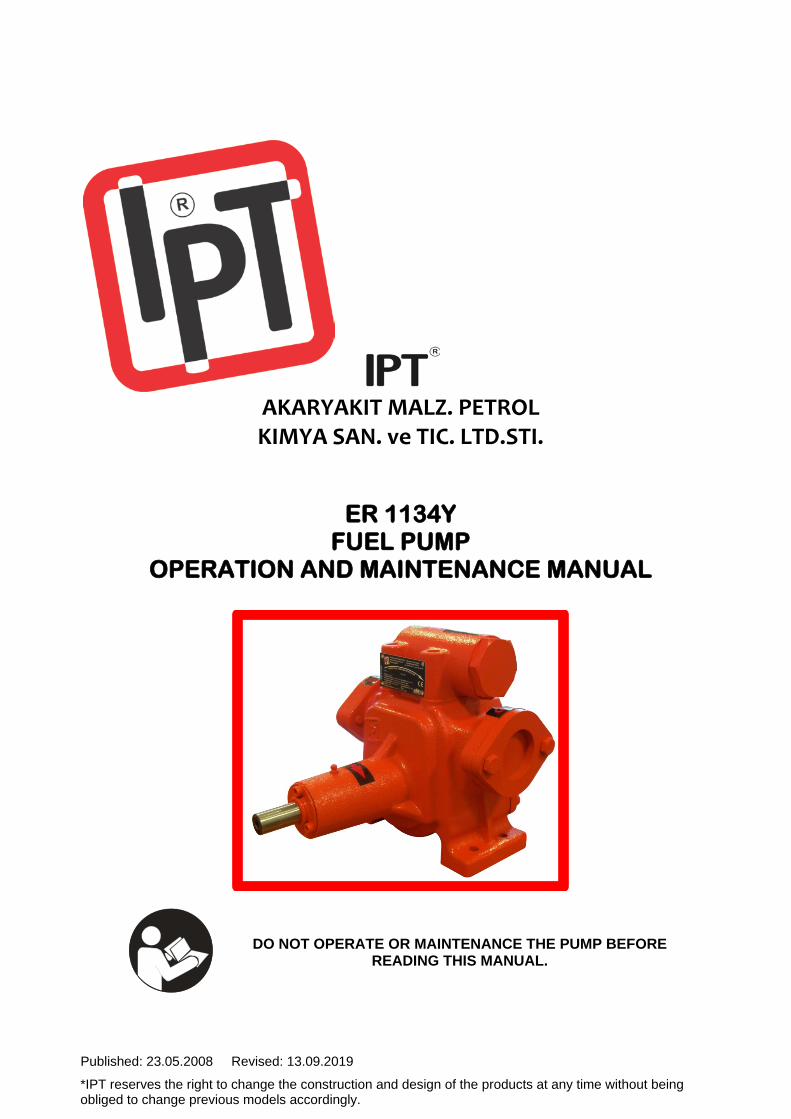
AKARYAKIT MALZ. PETROL KIMYA SAN. ve TIC. LTD.STI.
ER 1134Y FUEL PUMP
OPERATION AND MAINTENANCE MANUAL
DO NOT OPERATE OR MAINTENANCE THE PUMP BEFORE READING THIS MANUAL.
EU Declaration of Conformity according to ATEX Directive 2014/34/EU
Manufacturer lPT Akaryakit Malzemeleri Petrol Kimya Sanayi ve Ticaret Ltd.Sti 1. Organize Sanayi Bölgesi Türkmenistan Cad. No:15 Sincan Ankara / TURKIYE Declares hereby that the following products, if ordered as Atex pump, are meeting the requirements set Annex II in EU directive 2014/34/EU of 20 April 2016. If the product is modified without our written permission, or if the safety instructions in the instruction manuals are not being followed, this declaration becomes invalid. • Product : Eccentric Rotor Driven for ER 1134Y
• Notified body : Bureau Veritas, LCIE
33, Avenue du General Leclerc F 92260 Fontenay-Aux-Roses
• Certificate number : LCIE 08 ATEX 6100 X
II 2G c IIC T6 • Standards : Applicable harmonised standards
EN 13463-1 : 2009 EN 13463-5 : 2011
• Marking : The marking includes the symbol and the certificate number.
Special conditions for safe use are specified in the Instruction Manual.
Ankara, 17 June 2017
Mehmet Cemil ERDEM General Manager
1
CONTENTS 1. INTRODUCTION .................................... 1
1.1 Warnings .......................................... 1 1.2 General Information ......................... 2 1.3 Harmonized Standards .................... 2 1.4 Definitions ........................................ 3 1.5 Technical Specifications .................. 3 1.6 Marking ............................................ 3
2. SAFETY AND ENVIRONMENT ............. 4 2.1 General ............................................ 4 2.2 Users ............................................... 4 2.3 Safety Rules .................................... 4 2.4 Assembly, Maintenance and Repair 4 2.5 Environmentally ............................... 4
3. INSTALLATION ...................................... 5 3.1 Flushing the Pump ........................... 5 3.2 Positioning And Connections ........... 5
3.2.1 Dimensions ......................... 5 3.2.2 Connection and Assembly .. 5 3.2.3 Base Plate .......................... 5 3.2.4 Flange Couplings ................ 6 3.2.5 In-Line Drives ...................... 6 3.2.6 Belt Drives .......................... 7 3.2.7 By-Pass Valve .................... 8 3.2.8 Piping Configuration ........... 9 3.2.9 Direction of Rotation ......... 10
3.3 Earthing ......................................... 10 3.4 Electric Coupling ............................ 10 3.5 Paint ............................................... 11
4. OPERATION ......................................... 11 4.1 Control List ..................................... 11 4.2 Dry Running ................................... 12 4.3 Operation Principle ........................ 12 4.4 Initial Start-up ................................. 13
5. TRANSPORTATION-STORING ........... 13 5.1 Transportation ................................ 13 5.2 Storing ........................................... 13
6. MAINTENANCE .................................... 14 6.1 Filter ............................................... 14 6.2 Disassembly .................................. 15 6.3 Junk Pump ..................................... 16 6.4 Periyodic Maintenance .................. 17
7. TROUBLESHOOTING .......................... 17 8. RESIDUAL RISKS ................................ 19 9. GUARANTEE ....................................... 20
1.INTRODUCTION
This manual includes important information about effective and reliable operation of the pump. To obey the operation instructions brings effective operation, long pump life and avoid of risks.
• Try to understand the contents, • Follow the instructions and directions
complete and accurate, • Do not change the operation sequence, • Keep the manual and its copy near the
pump in case the operator can use anytime.
1.1.Warnings
This manual includes the necessary information as operation, maintenance, transportation etc. about ER 1134Y pump. Make the operator to pay the necessary attention to the manual and to keep the manual where he can access in any time.
This manual covers the operation and safety instructions have to be read before operating of the pump. IPT can not be hold responsible in case of improper use of the pump.
The pump was produced according to the technical safety rules. However it may harm for the operator and for the third person or can cause of any other damages.
The pump subject of this manual is composed of dynamic parts. Only the authorized persons must operate the pump.
Do not do any operation with the pump before reading the manual. Consult the IPT authorities in case of misunderstanding.
This product has to be used according to its intended use. IPT can not be hold responsible for the damage occured in case of misuse.
2
The necessary technical information about the operation and maintenance of the pump given in the title 1.5 and 1.6. Do not run out of this values.
Physical deformation may come into being in the sudden temperature changes. Do not operate in different than the design temperature.
The subject of this manual, ER 1134Y pump, just hand over as a pump machine and no controlling equipment will be given. The customer is responsible for supplying the connection and/or the controlling equipment.
The customer has to learn the specification and the harms of the liquid passing through the pump. Take the cautions to be pouring of harmful liquid.
Always work proper to the human health safety and environmental laws, regulations and instructions.
Safety Signs
Hazardous liquid may result to dangereous health problems in case of spreading to hand, to face and to skin.
Hazardous liquid may result to breathing problems.
Situation may result to fire, explosion, property loss or death.
Moving parts may result to woundings or rupture organs.
1.2.General Information
ER 1134Y (Idler Type) pump is a low pressurized, has a 1½” diameter of inlet/outlet dimensions and 180º inlet and outlet connections. Inner mechanism consist of cast iron parts. All the dynamic seals/gaskets are used to materials made of FKM or teflon in order to give reliable performance in the high petroleum products.
1.3.Harmonized Standards
Every ER 1134Y pump is designed and is being produced appropriate to the following standards. TS 6769-1 Metering pumps and dispensers to be installed at filling stations and used to dispense liquid fuel part 1:Specification for construction . TS EN 1127-1 Explosive atmospheres - Explosion prevention and protection - Part 1: Basic concepts and methodology TS EN 13617-1 Petrol filling stations – Part 1: Safety requirements for construction and performance of metering pumps, dispensers and remote pumping units TS EN 13617-2 Petrol filling stations - Part 2: Safety requirements for construction and performance of safe breaks for use on metering pumps and dispensers TS EN 13617-4 Petrol filling stations - Part 4: Safety requirements for construction and performance of swivels for use on metering pumps and dispensers TS EN 13980 Potentially explosive atmospheres - Application of quality systems TS EN 13463-1 Non-electrical equipment for potentially explosive atmospheres - Part 1: Basic method and requirements
3
TS EN 13463-5 Non-electrical equipment intended for use in potentially explosive atmospheres - Part 5: Protection by constructional safety "c"
1.4.Definitions
Meter Machine calculating the liquid being given or taken. Filter Equipment filtering the particles may exists in the liquid and may harm for the pump. Pump The machine taking the liquid in its place and transfer to the desired location with pressure. Rotor The part fixed to the main shaft and turning the idler in the pump casing. Idler The part rotating around its shaft fixed to the back cover and transferring liquid with the rotor. Seal The part used between a stable and a turning parts in order to prevent leakage. Viscosity The resistance of the liquid to flow. Gasket The rubber material setting between two stable mechanical parts to prevent leakage and impermeability.
1.5.Technical Specifications
Type Being in different center points, telescopic, with two parts turning in same direction
Inlet/Outlet Dia. 1½” Inlet/Outlet Flange - Diameter Capacity 140 lt/min (max.)
Operating Press. 6 bar (max.) Operating Temp. -20 / +60ºC Operating Speed up to 1200 rpm Operating Principle Eccentric Rotor Movement Drive Power 1.1 - 1.5 kw Gross Weight 20 kilos By-Pass Valve Coupled to body Viscosity 65,4 cSt (max.) Impermeability FKM (Viton) Material Material : Pump Casing : Cast Iron (PIG GG 25) Idler : Cast Iron (PIG GG 25) Rotor (diesel type) : Cast Iron (PIG GG 25) Rotor (gasoline type) : Bronze Shaft : Ck55 Induction
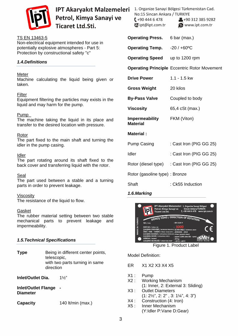
1.6.Marking
Figure 1. Product Label
Model Definition: ER X1 X2 X3 X4 X5 X1 : Pump X2 : Working Mechanism (1: Inner, 2: External 3: Sliding) X3 : Outlet Diameters (1: 2½”, 2: 2” , 3: 1¼”, 4: 3”) X4 : Construction (4: Iron) X5 : Inner Mechanism (Y:Idler P:Vane D:Gear)
4
Marking includes the type, working principle and serial number. In the reorder of pump or order of the spare parts, use the label information (type and serial no). If you need further information, please get in touch with IPT.
2.SAFETY AND ENVIRONMENT
2.1.General
The ER 1134Y pump you have bought was produced with high technology under the continuous quality control process. IPT can not be hold responsible for the damages and results occured in case of using out of its purpose. Not to obey the safety instructions means to endanger the human life, environment and the pump. Moreover the justs asking for the damage are being lost in case of not to obey the safety instructions. Not to obey the instructions may cause of the followings:
• Damage or failure in main functions of the pump
• Failure in the maintenance • Exposed of the human life to mechanical
and chemical damages • Environmental damage due to hazardous
liquid leakage. • Explosion
Special processes need special safety cautions. Ask IPT for advice in case of this kind of processes.
THE CUSTOMER IS RESPONSIBLE FOR OBEYING
THE LOCAL SAFETY LAWS AND COMPANY INSTRUCTIONS!
2.2.Users
The owner of the pump is responsible for ensuring that everyone who works with the pump has the necessary background. The operator shall explain the personnel’s responsibilities and authorities. If the operator
troubles with some points, he/she can demand a course from the manufacturer firm. As a last word, the responsible personel must understand the operating instructions exactly.
2.3.Safety Rules
The pump designed with high care. The original parts and the equipments meet the safety regulations. Making changes in design or not using original spare parts means to endanger the safety.
BE SURE THE PUMP IS OPERATED IN THE
TECHNICAL SPECIFICATION LIMITS. ONLY IN THIS CASE PUMP PERFORMANCE WILL
BE GUARANTEED! The signs and markings on the pump are the parts of safety conditions. These markings shall not be closed or unstitched. The markings shall be stay over the pump over the whole pump life. The markings outwear or getting older shall be changed with the new ones.
2.4. Assembly, Maintenance and Repair
All the assembly, maintenance and repair works must be done by the authorized personnel. Obey the local regulations.
WHILE DOING DRAINING, LEAKAGE REPAIR ETC.
WORK CAREFULLY CONSIDERING THE
ENVIRONMENTAL AND HUMAN HEALTH!
OBEY THE INSTRUCTIONS WRITTEN IN THE
INSTALLATION AND OPERATION SECTIONS WHEN OPERATING THE
PUMP AGAIN!
2.5.Environmentally
The IPT fuel pumps were designed to operate compatible to environment for all their lives. For this reason, use the biological oils in the maintenance.
5
The operator is responsible for discharging of the liquid without given damage to the environment. Pay care when discarding an adr of the pumps of which working life finished.
CONSULT LOCAL GOVERNMENT
ASSOCIATIONS FOR THE WASTE MATERIALS AND
RECYCLING!
3.INSTALLATION
3.1.Flushing The Pump
The pump was tested with diesel. If diesel may contaminate the liquid which will pass through the pump or if the diesel may react with the liquid, then flush the pump with the appropriate solvent completely. Read the instructions written in the ‘3.2.Positioning And Connections’ and ‘4.Operation’ sections.
3.2.Positioning and Connections
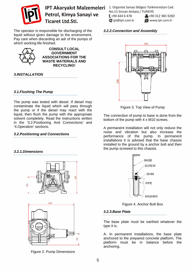
3.2.1.Dimensions
Figure 2. Pump Dimensions
3.2.2.Connection and Assembly
Figure 3. Top View of Pump The connection of pump to base is done from the bottom of the pump with 4 x M10 screws. A permanent installation will not only reduce the noise and vibration but also increase the performance of the pump. In permanent installations it is advised that the base chassis installed to the ground by a anchor bolt and then the pump screwed to this chassis.
Figure 4. Anchor Bolt Box
3.2.3.Base Plate
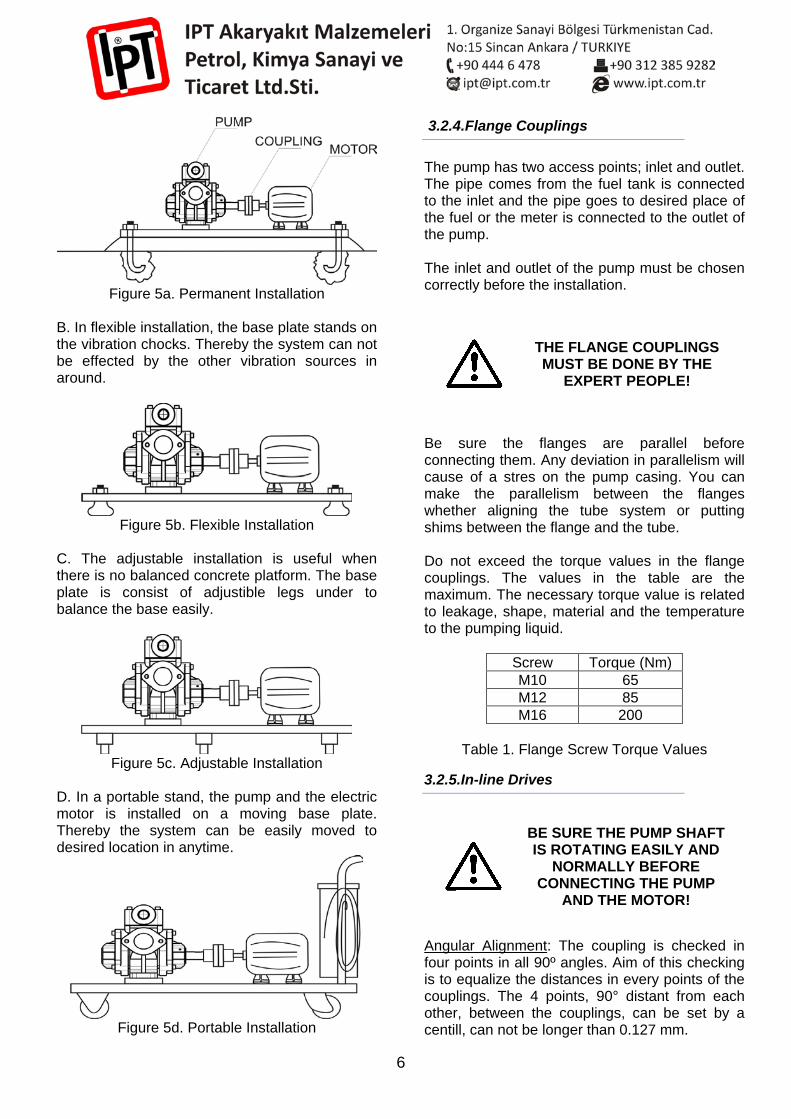
The base plate must be earthed whatever the type it is. A. In permanent installations, the base plate anchored to the prepared concrete platform. The platform must be in balance before the anchoring.
6
Figure 5a. Permanent Installation
B. In flexible installation, the base plate stands on the vibration chocks. Thereby the system can not be effected by the other vibration sources in around.
Figure 5b. Flexible Installation
C. The adjustable installation is useful when there is no balanced concrete platform. The base plate is consist of adjustible legs under to balance the base easily.
Figure 5c. Adjustable Installation
D. In a portable stand, the pump and the electric motor is installed on a moving base plate. Thereby the system can be easily moved to desired location in anytime.
Figure 5d. Portable Installation
3.2.4.Flange Couplings
The pump has two access points; inlet and outlet. The pipe comes from the fuel tank is connected to the inlet and the pipe goes to desired place of the fuel or the meter is connected to the outlet of the pump. The inlet and outlet of the pump must be chosen correctly before the installation.
THE FLANGE COUPLINGS MUST BE DONE BY THE
EXPERT PEOPLE!
Be sure the flanges are parallel before connecting them. Any deviation in parallelism will cause of a stres on the pump casing. You can make the parallelism between the flanges whether aligning the tube system or putting shims between the flange and the tube. Do not exceed the torque values in the flange couplings. The values in the table are the maximum. The necessary torque value is related to leakage, shape, material and the temperature to the pumping liquid.
Screw Torque (Nm) M10 65 M12 85 M16 200
Table 1. Flange Screw Torque Values
3.2.5.In-line Drives
BE SURE THE PUMP SHAFT IS ROTATING EASILY AND
NORMALLY BEFORE CONNECTING THE PUMP
AND THE MOTOR!
Angular Alignment: The coupling is checked in four points in all 90º angles. Aim of this checking is to equalize the distances in every points of the couplings. The 4 points, 90° distant from each other, between the couplings, can be set by a centill, can not be longer than 0.127 mm.
7
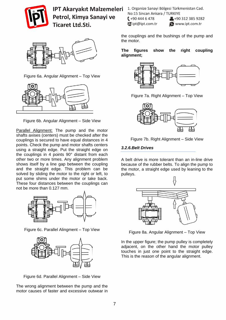
Figure 6a. Angular Alignment – Top View
Figure 6b. Angular Alignment – Side View Parallel Alignment: The pump and the motor shafts axises (centers) must be checked after the couplings is secured to have equal distances in 4 points. Check the pump and motor shafts centers using a straight edge. Put the straight edge on the couplings in 4 points 90° distant from each other two or more times. Any alignment problem shows itself by a line gap between the coupling and the straight edge. This problem can be solved by sliding the motor to the right or left, to put some shims under the motor or take back. These four distances between the couplings can not be more than 0.127 mm.
Figure 6c. Parallel Alingment – Top View
Figure 6d. Parallel Alignment – Side View The wrong alignment between the pump and the motor causes of faster and excessive outwear in
the couplings and the bushings of the pump and the motor. The figures show the right coupling alignment;
Figure 7a. Right Alignment – Top View
Figure 7b. Right Alignment – Side View
3.2.6.Belt Drives
A belt drive is more tolerant than an in-line drive because of the rubber belts. To align the pump to the motor, a straight edge used by leaning to the pulleys.
Figure 8a. Angular Alignment – Top View
In the upper figure; the pump pulley is completely adjacent, on the other hand the motor pulley touches in just one point to the straight edge. This is the reason of the angular alignment.
8
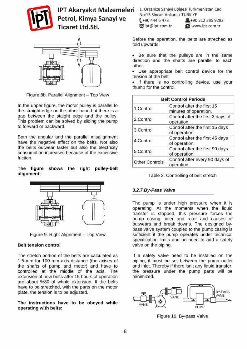
Figure 8b. Parallel Alignment – Top View
In the upper figure, the motor pulley is parallel to the straight edge on the other hand but there is a gap between the staight edge and the pulley. This problem can be solved by sliding the pump to forward or backward. Both the angular and the parallel misalignment have the negative effect on the belts. Not also the belts outwear faster but also the electricity consumption increases because of the excessive friction. The figure shows the right pulley-belt alignment;
Figure 9. Right Alignment – Top View Belt tension control The stretch portion of the belts are calculated as 1.5 mm for 100 mm axis distance (the axises of the shafts of pump and motor) and have to controlled at the middle of the axis. The extension of new belts after 15 hours of operation are about %80 of whole extension. If the belts have to be stretched, with the parts on the motor plate, the tension is to be adjusted. The instructions have to be obeyed while operating with belts:
Before the operation, the belts are streched as told upwards. • Be sure that the pulleys are in the same direction and the shafts are parallel to each other. • Use appropriate belt control device for the tension of the belt. • If there is no controlling device, use your thumb for the control.
Belt Control Periods
1.Control Control after the first 15 minutes of operation.
2.Control Control after the first 3 days of operation.
3.Control Control after the first 15 days of operation.
4.Control Control after the first 45 days of operation.
5.Control Control after the first 90 days of operation.
Other Controls Control after every 90 days of operation.
Table 2. Controlling of belt stretch
3.2.7.By-Pass Valve
The pump is under high pressure when it is operating. At the moments when the liquid transfer is stopped, this pressure forces the pump casing, idler and rotor and causes of outwears and break downs. The designed by-pass valve system coupled to the pump casing is sufficient if the pump operates under technical specification limits and no need to add a safety valve on the piping. If a safety valve need to be installed on the piping, it must be set between the pump outlet and inlet. Thereby if there isn’t any liquid transfer, the pressure under the pump parts will be minimized.
Figure 10. By-pass Valve
9
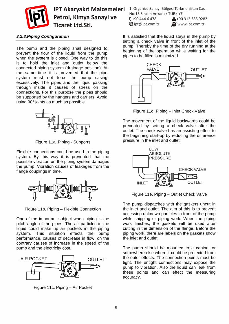
3.2.8.Piping Configuration
The pump and the piping shall designed to prevent the flow of the liquid from the pump when the system is closed. One way to do this is to hold the inlet and outlet below the connected piping system (drainage position). At the same time it is prevented that the pipe system must not force the pump casing excessively. The pipes and the liquid passing through inside it causes of stress on the connections. For this purpose the pipes should be supported by the hangers and carriers. Avoid using 90° joints as much as possible.
Figure 11a. Piping - Supports Flexible connections could be used in the piping system. By this way it is prevented that the possible vibration on the piping system damages the pump. Vibration causes of leakages from the flange couplings in time.
Figure 11b. Piping – Flexible Connection One of the important subject when piping is the pitch angle of the pipes. The air particles in the liquid could make up air pockets in the piping system. This situation effects the pump performance, causes of decrease in flow, on the contrary causes of increase in the speed of the pump and the electricity cost.
Figure 11c. Piping – Air Pocket
It is satisfied that the liquid stays in the pump by setting a check valve in front of the inlet of the pump. Thereby the time of the dry running at the beginning of the operation while waiting for the pipes to be filled is minimized.
Figure 11d. Piping – Inlet Check Valve
The movement of the liquid backwards could be prevented by setting a check valve after the outlet. The check valve has an assisting effect to the beginning start-up by reducing the difference pressure in the inlet and outlet.
Figure 11e. Piping – Outlet Check Valve The pump dispatches with the gaskets uncut in the inlet and outlet. The aim of this is to prevent accessing unknown particles in front of the pump while shipping or piping work. When the piping work finishes, the gaskets will be used after cutting in the dimension of the flange. Before the piping work, there are labels on the gaskets show the inlet and outlet. The pump should be mounted to a cabinet or somewhere else where it could be protected from the outer effects. The connection points must be tight. The untight connections may expose the pump to vibration. Also the liquid can leak from these points and can effect the measuring accuracy.
10
WHEN DOING INLET AND OUTLET CONNECTIONS, BE SURE THAT THE WELDING
SLAGS / METAL FILLINGS DO NOT ACCESS IN FRONT OF
THE PUMP! The screws and nuts tightness must be done according to the following table. The excessive torque may cause of stripping of the screw or the inadequate torque may cause of leaking from the gaskets.
Connected Parts Figure
17 Poz No
Screw/Nut (radius*thread)
Torque (N*mt)
Dust seal / Casing 01 M6*1 13 By-pass casing /
Casing 15 M8*1.25 24
Back Cover / Casing 31 M10*1.5 45
Table 3. Screw/Nut Torque Values
THE SCREWS/NUTS TIGHTEN UNSUFFICIENT
MAY CAUSE OF LEAKAGE FROM THE GASKETS. THE ACCUMULATING LIQUID MAY CAUSE OF FIRE OR
EXPLOSION!
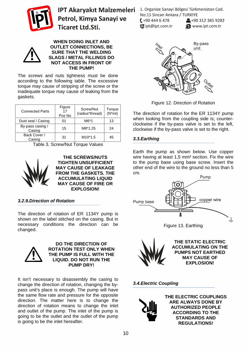
3.2.9.Direction of Rotation
The direction of rotation of ER 1134Y pump is shown on the label stitched on the casing. But in necessary conditions the direction can be changed.
DO THE DIRECTION OF ROTATION TEST ONLY WHEN THE PUMP IS FULL WITH THE
LIQUID. DO NOT RUN THE PUMP DRY!
It isn’t necessary to disassembly the casing to change the direction of rotation, changing the by-pass unit’s place is enough. The pump will have the same flow rate and pressure for the opposite direction. The matter here is to change the direction of rotation means to change the inlet and outlet of the pump. The inlet of the pump is going to be the outlet and the outlet of the pump is going to be the inlet hereafter.
Figure 12. Direction of Rotation The direction of rotation for the ER 1134Y pump when looking from the coupling side is; counter-clockwise if the by-pass valve is set to the left, clockwise if the by-pass valve is set to the right.
3.3.Earthing
Earth the pump as shown below. Use copper wire having at least 1,5 mm² section. Fix the wire to the pump base using base screw. Insert the other end of the wire to the ground no less than 5 cm.
Figure 13. Earthing
THE STATIC ELECTRIC ACCUMULATING ON THE
PUMPS NOT EARTHED MAY CAUSE OF
EXPLOSION!
3.4.Electric Coupling
THE ELECTRIC COUPLINGS ARE ALWAYS DONE BY AUTHORIZED PEOPLE ACCORDING TO THE
STANDARDS AND REGULATIONS!

11
The electric couplings must be done according to the instructions and related regulations by a qualified electrician. Not to obey this instructions may cause of serious traumas, deaths or physical damage. Use a motor switch appropriate to the motor’s nominal current. Control the local electric voltage is the same as the motor voltage written in the label, and the direction of rotation of the motor is the same as the pump.
A THERMIC APPROPRIATE TO MOTOR POWER MUST BE SET
BEFORE THE ELECTRIC SYSTEM OF THE MOTOR IN
ORDER TO PREVENT DAMAGE IN CASE OF ANY BREAK
DOWNS OR FORCING!
3.5.Paint
The paint used for the pumps is the Styrene alkid solvent based primer paint. The high water resistanant paint protects the pump from corrosion.
THE PAINT USED CAN BE RESOLVED IN THE
PETROLEUM PRODUCTS. DO NOT EXPOSE THE PUMP’S
EXTERIOR SURFACE TO THIS KIND OF SUBSTANCES!
4.OPERATION
When working with hazardous liquids or maintaning the pump, wear protective clothes, use protective glasses or face mask.
To get in touch with hazardous liquids, to swallow, splashing to eyes, to smudge of the body or breathing the vapours of them without taking appropriate precautions may cause of serious traumas or even death. Take the necessary safety precautions while working with the hazardous liquids.
To change the parts or accessories of the pump, to use outwear or damaged parts, to use liquids or chemical substances inappropriate to inner mechanism of the pump can damage the pump parts. In such a case the subjected liquid may pour, smudge to the body or splash to the eyes. According to the type of the liquid, this situation may cause of fire, explosion, thereby to loss of human life and property.
The pump consists of rotating parts. To insert an organ like finger to these parts without taking safety precautions may cause of woundings or rupturing an organ.
4.1.Control List
The following clauses must be controlled before operating of the pump;
1. That the pump should be earthed. 2. That the pump shaft can be turned
around freely. 3. That the pump is connected to an
explosion-proof motor, if the pump is set up in a potentially explosive atmosphere.
4. That the pump and motor are aligned precisely.
5. That the thread of the temperature sensor has not broken off during transportation,
12
handling or installation, if the pump is fitted with temperature sensor
6. That all isolating valves in the inlet and outlet pipe are fully open, to avoid the pressure being too high and the pump running dry.
7. That any by-pass valve is fitted correctly. 8. That there is no coagulated liquid in the
pump or the pipe system after the last operation that may cause blockage or breakdown.
Controlling after a long storage time If the pump has been in storage for a long period of time, the followings are to be checked;
1. That the pump is not corroded or dried out,
2. That the pump shaft can be turned around freely,
3. That any preservative or anti-frost liquid is cleaned off before starting the pump if these are not compatible with the pump liquid,
4. That elastomers are replaced if they have been damaged by the anti-frost liquid used,
5. That gasket and seal maintain their elasticity. If the pump has been in storage for more than 6 years, it is recommended that these parts are changed.
After controlling all these clauses, the pump is ready for the operating. While the operating, the gun, valve etc. equipments after the pump must not be kept close long durations, so the pump must not be exposed to high pressures. After the pumping operation, the gun, valve etc. equipment must be closed and the pump must be shut down immediately.
4.2.Dry Run
The pump should be protected against dry running. Otherwise it will expose to unnecessary abbrasion and breaks down. Dry running causes heat to develop and the possible creation of sparks by the pump casing and iner mechanism.
The pumps produced for the potentially explosive atmospheres must be protected against dry running.
NEVER DRY RUN A PUMP BECAUSE OF POSSIBLE CREATION OF SPARKS
AND MAY CAUSE OF EXPLOSION!
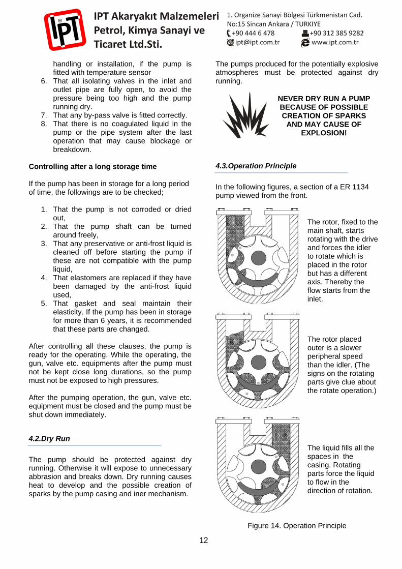
4.3.Operation Principle
In the following figures, a section of a ER 1134 pump viewed from the front.
The rotor, fixed to the main shaft, starts rotating with the drive and forces the idler to rotate which is placed in the rotor but has a different axis. Thereby the flow starts from the inlet.
The rotor placed outer is a slower peripheral speed than the idler. (The signs on the rotating parts give clue about the rotate operation.)
The liquid fills all the spaces in the casing. Rotating parts force the liquid to flow in the direction of rotation.
Figure 14. Operation Principle
13
4.4.Initial Start-Up
In a new and dry system, when the vanes open, there may be a high pressure in the piping system and this pressure pass through the pump by force. The high pressure and the air volume makes the pump operating faster. The suggested start-up procedure for any system is overflowing the piping system gradually. This enables the pump to discard the air slowly from the piping.
Protecting Unknown Particles In new piping systems, attention must be paid to protect the pump in start-up. Welding slacks, corrosion, sludges may cause of damage in the pump. To protect the pump against these kind of damages, control the filters set up before the inlet of the pump.
5.TRANSPORTATION-STORING
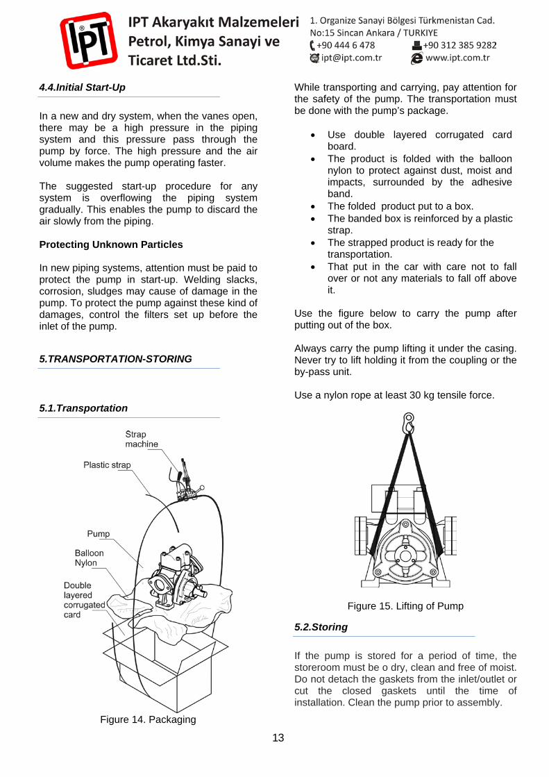
5.1.Transportation
Figure 14. Packaging
While transporting and carrying, pay attention for the safety of the pump. The transportation must be done with the pump’s package.
• Use double layered corrugated card board.
• The product is folded with the balloon nylon to protect against dust, moist and impacts, surrounded by the adhesive band.
• The folded product put to a box. • The banded box is reinforced by a plastic
strap. • The strapped product is ready for the
transportation. • That put in the car with care not to fall
over or not any materials to fall off above it.
Use the figure below to carry the pump after putting out of the box. Always carry the pump lifting it under the casing. Never try to lift holding it from the coupling or the by-pass unit. Use a nylon rope at least 30 kg tensile force.
Figure 15. Lifting of Pump
5.2.Storing
If the pump is stored for a period of time, the storeroom must be o dry, clean and free of moist. Do not detach the gaskets from the inlet/outlet or cut the closed gaskets until the time of installation. Clean the pump prior to assembly.
14
1. To store the pump left in the system, flow about 150 liters of clean water through the pump.
2. After that, pump %70 antifreeze and %30 water mixture to all the system (instead of the mixture, %100 RV antifreeze can be used). While the pump is operating, close one of a valve after the pump to guarantee the antifreeze solution will be kept in this zone. After that close one of a valve before the inlet of the pump, thereby you will be sure the pump is full of antifreeze solution.
3. Before starting the system after storing, do not forget to apply the clauses written in the title of “4.1. Control List” .
6.MAINTENANCE
The pumping liquid is hazardous for the skin. Use full face mask (if not use glasses) and wear your plastic gloves. To protect your skin against smudging the liquid.
The pumping liquid is hazardous for breathing. In case of breathing, head ache, vertigo or more serious health problems may occur. Stop your work and go out for a fresh air immediately!
The possibility of a spark result to rubbing of two metals, assembling or disassembling is very dangereous when there is liquid in the pump. A fire or an explosion danger exists according to the specification of the liquid.
The pump consists of rotating parts. To insert an organ like finger to these parts without taking safety precautions may cause of woundings or rupturing an organ.
We recommend you to keep records of the periodic or other controls and maintenances. To apply this kind of maintenance procedure will make your pump work in good condition and prevent from the high cost malfunctions.
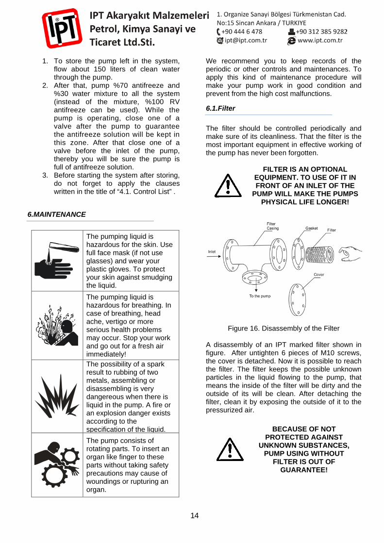
6.1.Filter
The filter should be controlled periodically and make sure of its cleanliness. That the filter is the most important equipment in effective working of the pump has never been forgotten.
FILTER IS AN OPTIONAL EQUIPMENT. TO USE OF IT IN FRONT OF AN INLET OF THE
PUMP WILL MAKE THE PUMPS PHYSICAL LIFE LONGER!
Figure 16. Disassembly of the Filter A disassembly of an IPT marked filter shown in figure. After untighten 6 pieces of M10 screws, the cover is detached. Now it is possible to reach the filter. The filter keeps the possible unknown particles in the liquid flowing to the pump, that means the inside of the filter will be dirty and the outside of its will be clean. After detaching the filter, clean it by exposing the outside of it to the pressurized air.
BECAUSE OF NOT PROTECTED AGAINST
UNKNOWN SUBSTANCES, PUMP USING WITHOUT
FILTER IS OUT OF GUARANTEE!
15
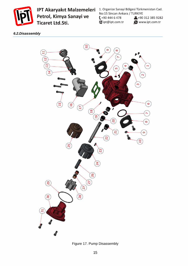
6.2.Disassembly
Figure 17. Pump Disassembly
16
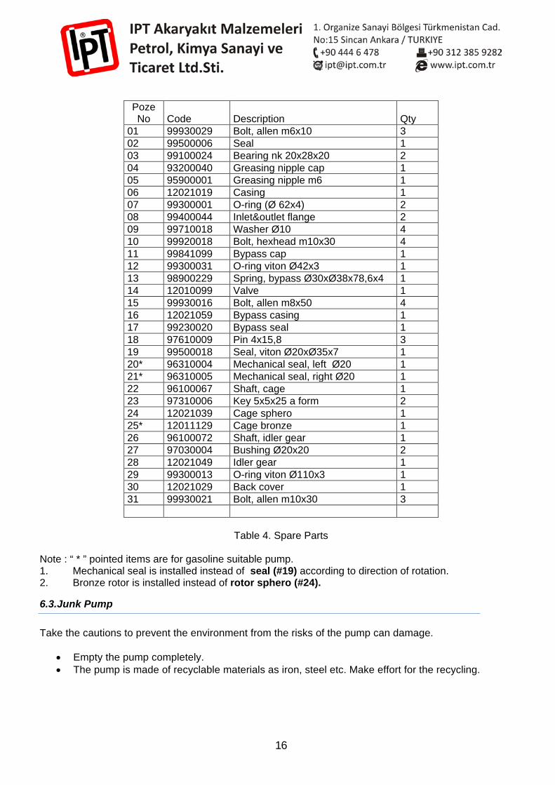
Poze No Code Description Qty
01 99930029 Bolt, allen m6x10 3 02 99500006 Seal 1 03 99100024 Bearing nk 20x28x20 2 04 93200040 Greasing nipple cap 1 05 95900001 Greasing nipple m6 1 06 12021019 Casing 1 07 99300001 O-ring (Ø 62x4) 2 08 99400044 Inlet&outlet flange 2 09 99710018 Washer Ø10 4 10 99920018 Bolt, hexhead m10x30 4 11 99841099 Bypass cap 1 12 99300031 O-ring viton Ø42x3 1 13 98900229 Spring, bypass Ø30xØ38x78,6x4 1 14 12010099 Valve 1 15 99930016 Bolt, allen m8x50 4 16 12021059 Bypass casing 1 17 99230020 Bypass seal 1 18 97610009 Pin 4x15,8 3 19 99500018 Seal, viton Ø20xØ35x7 1 20* 96310004 Mechanical seal, left Ø20 1 21* 96310005 Mechanical seal, right Ø20 1 22 96100067 Shaft, cage 1 23 97310006 Key 5x5x25 a form 2 24 12021039 Cage sphero 1 25* 12011129 Cage bronze 1 26 96100072 Shaft, idler gear 1 27 97030004 Bushing Ø20x20 2 28 12021049 Idler gear 1 29 99300013 O-ring viton Ø110x3 1 30 12021029 Back cover 1 31 99930021 Bolt, allen m10x30 3
Table 4. Spare Parts
Note : “ * ” pointed items are for gasoline suitable pump. 1. Mechanical seal is installed instead of seal (#19) according to direction of rotation. 2. Bronze rotor is installed instead of rotor sphero (#24).
6.3.Junk Pump
Take the cautions to prevent the environment from the risks of the pump can damage.
• Empty the pump completely. • The pump is made of recyclable materials as iron, steel etc. Make effort for the recycling.
17
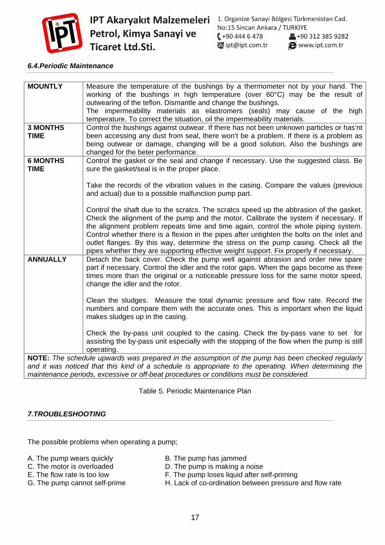
6.4.Periodic Maintenance
MOUNTLY Measure the temperature of the bushings by a thermometer not by your hand. The working of the bushings in high temperature (over 60°C) may be the result of outwearing of the teflon. Dismantle and change the bushings. The impermeability materials as elastromers (seals) may cause of the high temperature. To correct the situation, oil the impermeability materials.
3 MONTHS TIME
Control the bushings against outwear. If there has not been unknown particles or has’nt been accessing any dust from seal, there won’t be a problem. If there is a problem as being outwear or damage, changing will be a good solution. Also the bushings are changed for the beter performance.
6 MONTHS TIME
Control the gasket or the seal and change if necessary. Use the suggested class. Be sure the gasket/seal is in the proper place. Take the records of the vibration values in the casing. Compare the values (previous and actual) due to a possible malfunction pump part. Control the shaft due to the scratcs. The scratcs speed up the abbrasion of the gasket. Check the alignment of the pump and the motor. Calibrate the system if necessary. If the alignment problem repeats time and time again, control the whole piping system. Control whether there is a flexion in the pipes after untighten the bolts on the inlet and outlet flanges. By this way, determine the stress on the pump casing. Check all the pipes whether they are supporting effective weight support. Fix properly if necessary.
ANNUALLY Detach the back cover. Check the pump well against abrasion and order new spare part if necessary. Control the idler and the rotor gaps. When the gaps become as three times more than the original or a noticeable pressure loss for the same motor speed, change the idler and the rotor. Clean the sludges. Measure the total dynamic pressure and flow rate. Record the numbers and compare them with the accurate ones. This is important when the liquid makes sludges up in the casing. Check the by-pass unit coupled to the casing. Check the by-pass vane to set for assisting the by-pass unit especially with the stopping of the flow when the pump is still operating.
NOTE: The schedule upwards was prepared in the assumption of the pump has been checked regularly and it was noticed that this kind of a schedule is appropriate to the operating. When determining the maintenance periods, excessive or off-beat procedures or conditions must be considered.
Table 5. Periodic Maintenance Plan
7.TROUBLESHOOTING
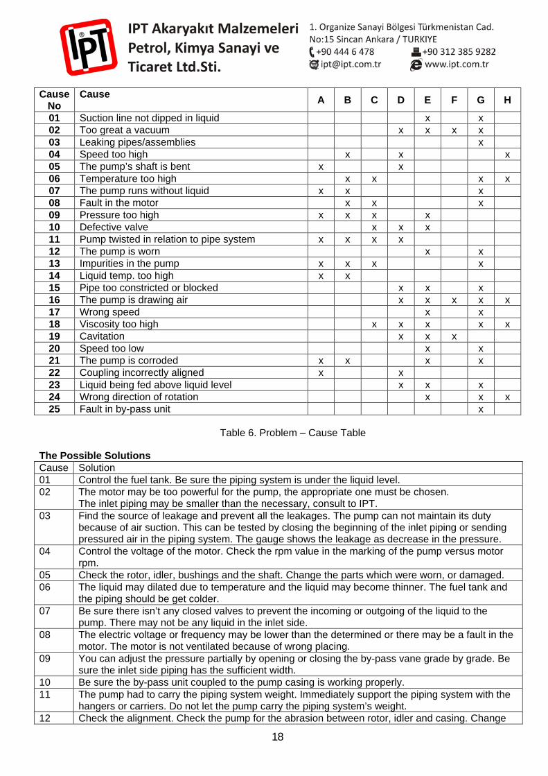
The possible problems when operating a pump; A. The pump wears quickly B. The pump has jammed C. The motor is overloaded D. The pump is making a noise E. The flow rate is too low F. The pump loses liquid after self-priming G. The pump cannot self-prime H. Lack of co-ordination between pressure and flow rate
18
Cause No
Cause A B C D E F G H
01 Suction line not dipped in liquid x x 02 Too great a vacuum x x x x 03 Leaking pipes/assemblies x 04 Speed too high x x x 05 The pump’s shaft is bent x x 06 Temperature too high x x x x 07 The pump runs without liquid x x x 08 Fault in the motor x x x 09 Pressure too high x x x x 10 Defective valve x x x 11 Pump twisted in relation to pipe system x x x x 12 The pump is worn x x 13 Impurities in the pump x x x x 14 Liquid temp. too high x x 15 Pipe too constricted or blocked x x x 16 The pump is drawing air x x x x x 17 Wrong speed x x 18 Viscosity too high x x x x x 19 Cavitation x x x 20 Speed too low x x 21 The pump is corroded x x x x 22 Coupling incorrectly aligned x x 23 Liquid being fed above liquid level x x x 24 Wrong direction of rotation x x x 25 Fault in by-pass unit x
Sorun Table 6. Problem – Cause Table
The Possible Solutions Cause Solution 01 Control the fuel tank. Be sure the piping system is under the liquid level. 02 The motor may be too powerful for the pump, the appropriate one must be chosen.
The inlet piping may be smaller than the necessary, consult to IPT. 03 Find the source of leakage and prevent all the leakages. The pump can not maintain its duty
because of air suction. This can be tested by closing the beginning of the inlet piping or sending pressured air in the piping system. The gauge shows the leakage as decrease in the pressure.
04 Control the voltage of the motor. Check the rpm value in the marking of the pump versus motor rpm.
05 Check the rotor, idler, bushings and the shaft. Change the parts which were worn, or damaged. 06 The liquid may dilated due to temperature and the liquid may become thinner. The fuel tank and
the piping should be get colder. 07 Be sure there isn’t any closed valves to prevent the incoming or outgoing of the liquid to the
pump. There may not be any liquid in the inlet side. 08 The electric voltage or frequency may be lower than the determined or there may be a fault in the
motor. The motor is not ventilated because of wrong placing. 09 You can adjust the pressure partially by opening or closing the by-pass vane grade by grade. Be
sure the inlet side piping has the sufficient width. 10 Be sure the by-pass unit coupled to the pump casing is working properly. 11 The pump had to carry the piping system weight. Immediately support the piping system with the
hangers or carriers. Do not let the pump carry the piping system’s weight. 12 Check the alignment. Check the pump for the abrasion between rotor, idler and casing. Change
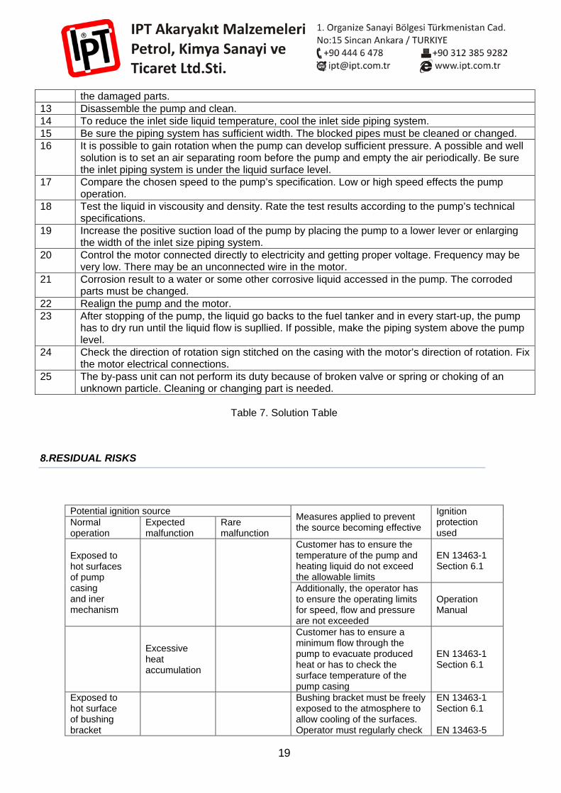
19
the damaged parts. 13 Disassemble the pump and clean. 14 To reduce the inlet side liquid temperature, cool the inlet side piping system. 15 Be sure the piping system has sufficient width. The blocked pipes must be cleaned or changed. 16 It is possible to gain rotation when the pump can develop sufficient pressure. A possible and well
solution is to set an air separating room before the pump and empty the air periodically. Be sure the inlet piping system is under the liquid surface level.
17 Compare the chosen speed to the pump’s specification. Low or high speed effects the pump operation.
18 Test the liquid in viscousity and density. Rate the test results according to the pump’s technical specifications.
19 Increase the positive suction load of the pump by placing the pump to a lower lever or enlarging the width of the inlet size piping system.
20 Control the motor connected directly to electricity and getting proper voltage. Frequency may be very low. There may be an unconnected wire in the motor.
21 Corrosion result to a water or some other corrosive liquid accessed in the pump. The corroded parts must be changed.
22 Realign the pump and the motor. 23 After stopping of the pump, the liquid go backs to the fuel tanker and in every start-up, the pump
has to dry run until the liquid flow is supllied. If possible, make the piping system above the pump level.
24 Check the direction of rotation sign stitched on the casing with the motor’s direction of rotation. Fix the motor electrical connections.
25 The by-pass unit can not perform its duty because of broken valve or spring or choking of an unknown particle. Cleaning or changing part is needed.
Table 7. Solution Table
8.RESIDUAL RISKS
Potential ignition source Measures applied to prevent the source becoming effective
Ignition protection used
Normal operation
Expected malfunction
Rare malfunction
Exposed to hot surfaces of pump casing and iner mechanism
Customer has to ensure the temperature of the pump and heating liquid do not exceed the allowable limits
EN 13463-1 Section 6.1
Additionally, the operator has to ensure the operating limits for speed, flow and pressure are not exceeded
Operation Manual
Excessive heat accumulation
Customer has to ensure a minimum flow through the pump to evacuate produced heat or has to check the surface temperature of the pump casing
EN 13463-1 Section 6.1
Exposed to hot surface of bushing bracket
Bushing bracket must be freely exposed to the atmosphere to allow cooling of the surfaces. Operator must regularly check
EN 13463-1 Section 6.1
EN 13463-5
20
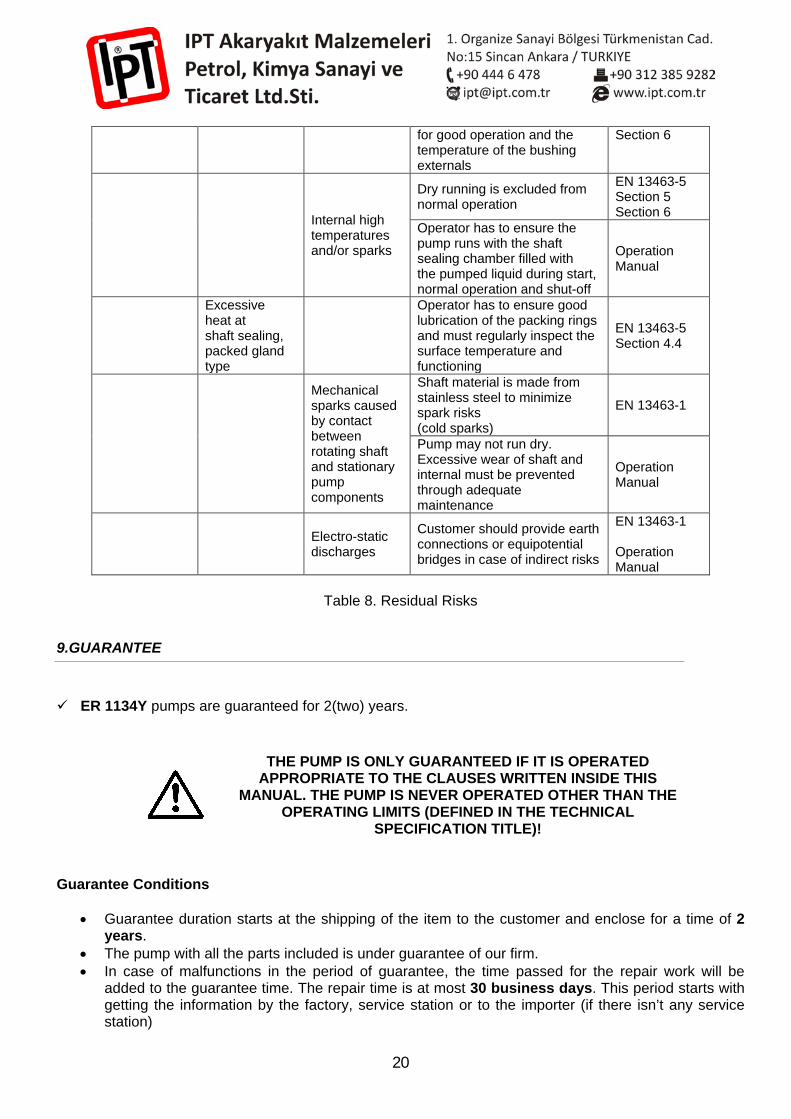
for good operation and the temperature of the bushing externals
Section 6
Internal high temperatures and/or sparks
Dry running is excluded from normal operation
EN 13463-5 Section 5 Section 6
Operator has to ensure the pump runs with the shaft sealing chamber filled with the pumped liquid during start, normal operation and shut-off
Operation Manual
Excessive heat at shaft sealing, packed gland type
Operator has to ensure good lubrication of the packing rings and must regularly inspect the surface temperature and functioning
EN 13463-5 Section 4.4
Mechanical sparks caused by contact between rotating shaft and stationary pump components
Shaft material is made from stainless steel to minimize spark risks (cold sparks)
EN 13463-1
Pump may not run dry. Excessive wear of shaft and internal must be prevented through adequate maintenance
Operation Manual
Electro-static discharges
Customer should provide earth connections or equipotential bridges in case of indirect risks
EN 13463-1 Operation Manual
Table 8. Residual Risks
9.GUARANTEE
ER 1134Y pumps are guaranteed for 2(two) years.
THE PUMP IS ONLY GUARANTEED IF IT IS OPERATED APPROPRIATE TO THE CLAUSES WRITTEN INSIDE THIS
MANUAL. THE PUMP IS NEVER OPERATED OTHER THAN THE OPERATING LIMITS (DEFINED IN THE TECHNICAL
SPECIFICATION TITLE)!
Guarantee Conditions
• Guarantee duration starts at the shipping of the item to the customer and enclose for a time of 2 years.
• The pump with all the parts included is under guarantee of our firm. • In case of malfunctions in the period of guarantee, the time passed for the repair work will be
added to the guarantee time. The repair time is at most 30 business days. This period starts with getting the information by the factory, service station or to the importer (if there isn’t any service station)
21
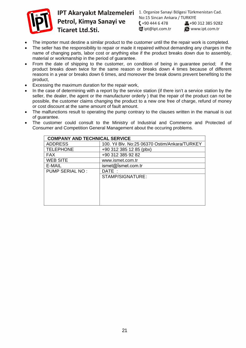
• The importer must destine a similar product to the customer until the the repair work is completed. • The seller has the responsibility to repair or made it repaired without demanding any charges in the
name of changing parts, labor cost or anything else if the product breaks down due to assembly, material or workmanship in the period of guarantee.
• From the date of shipping to the customer, on condition of being in guarantee period; if the product breaks down twice for the same reason or breaks down 4 times because of different reasons in a year or breaks down 6 times, and moreover the break downs prevent benefiting to the product,
• Excessing the maximum duration for the repair work, • In the case of determining with a report by the service station (if there isn’t a service station by the
seller, the dealer, the agent or the manufacturer orderly ) that the repair of the product can not be possible, the customer claims changing the product to a new one free of charge, refund of money or cost discount at the same amount of fault amount.
• The malfunctions result to operating the pump contrary to the clauses written in the manual is out of guarantee.
• The customer could consult to the Ministry of Industrial and Commerce and Protected of Consumer and Competition General Management about the occuring problems.
COMPANY AND TECHNICAL SERVICE ADDRESS 100. Yil Blv. No:25 06370 Ostim/Ankara/TURKEY TELEPHONE +90 312 385 12 85 (pbx) FAX +90 312 385 92 82 WEB SITE www.ismet.com.tr E-MAIL ismet@İsmet.com.tr PUMP SERIAL NO :
DATE : STAMP/SIGNATURE :