Embed Size (px)
Citation preview
AK A.24v 027 24 K)
liii I I 11111j;Iii~~~4 qil.v{.ijj:
I IN3'I r 1~q '
-C2'A 4L,, r'k
BEST'
A"4 LE 0
ma 4~'4~'~, t*.C.4

Destroy this report when no longer needed. Do not returnit to the originator.
The findings in this report ore not to be construed as an officialDepartment of the Army position unless so designated
by other authorized documents.
This program is furnished by the Government and is accepted and usedby the recipient with the express understanding that the United StatesGovernment makes no warranties, expressed or implied, concerning theaccuracy, completeness, reliability, usability, or suitability for anyparticular purpose of the information and data contained in this pro-gram or furnished in connection therewith, and the United States shallbe under no liability whatsoever to any person by reason of any usemade thereof. Th )rogram belongs to the Government. Therefore, therecipient further agrees not to assertany proprietary rights therein ortorepresent this program to anyone as other than a Government program.
The contents of this report are not to be used foradvertising, publication, or promotional purposes.Citation of trade names does not constitute anofficial endorsement or approval of the use of
such commercial products.
Form ApprovedREPORT DOCUMENTATION PAGE OMB No. O7o4-0188
Puwgc r n tuiden cOIt."iai o.n of infett.oi isu tiatedi to a je.~ I "'iO t C' 'C100 ., ncuding the time for re.,.eW'l .. t-tIICtl1fi. searchIng e-rStIn data sorces.9henw.rq an ntarMn9 th ta needed. aid .-.p!et.ng and re .er .i the cofloctiOn of information. Send comments regarding this bLxden estimate or any other aspet of thiscollection of informatiOn. sudng su sto for reduing this burden to adastington Headquarters Servce%. Dire orate for information Operations and Reports. 1215 JeffersonDams Hi';vaj. Suite 1204. A~rlgtcn. VA 22202-4302. and t to .Office oM l anagemient and Sudge. Pa ervork Reduction Project (0704-0183).Washtigton. DC 20503
1. AGENCY USE ONLY (Leave blank) 2. REPORT DATE 13. REPORT TYPE AND DATES COVERED
March 1992 Final Report4. TITLE AND SUBTITLE 5. FUNDING NUMBERS
USER'S GUIDE FOR CONCRETE STRENGTH INVESTIGATIONAND DESIGN (CASTR) IN ACCORDANCE WITH ACI 318-89
6. AUTHOR(S)
Clifton C. Hamby, William A. Price III
7. PERFORMING ORGANIZATION NAME(S) AND ADDRESS(ES) 8. PERFORMING ORGANIZATIONREPORT NUMBER
USAE Waterways Experiment Station
Information Technology Laboratory Instruction Report3909 Halls Ferry Road ITL-87-2 (Revised)Vicksburg, MS 39180-6199
9. SPONSORING/ MONITORING AGENCY NAME(S) AND ADDRESS(ES) 10. SPONSORING/ MONITORINGAGENCY REPORT NUMBER
DEPARTMENT OF THE ARMYUS Army Corps of EngineersWashington, DC 20314-1000
11. SUPPLEMENTARY NOTES
This report supersedes Instruction Report ITL-87-2; available from Nat.onal Tech-nical Information Service, 5285 Port Royal Road, Springfield, VA 22161,
12a. DISTRIBUTION/AVAILABILITY STATEMENT 12b. D;TRIBUTION CODE
Approved for public release; distribution is unlimited.
13. ABSTRACT (Maximum 200 words)
Program CASTR is versatile in that its capabilities extend from design ofnew concrete structures in accordance with ACI 318-89 to investigation ofalready existing designs. Its analysis is based on the rectangular stress block
described in Section 10.2.7 of the ACI Code 318.
The design procedure is computer-aided rather than automatic, computes theminimum reinforcement required for a given width and depth, and displays the
resulting interaction diagram. The program also computes and prints the minimum
effective depth of a given section which satisfies strength requirements without
compressive reinforcement.
The investigation procedure shows interaction diagrams and calculates com-
pliance with ductile failure criteria.
14. SUBJECT TERMS 15. NUMBFR OF PAGES
65See reverse 16. PRICE CODE
17 SECURITY CLASSIFICATION 18. SECURITY CLASSIFICATION 19. SECURITY CLASSIFICATION 20. LIMITATION OF ABSTRACT
OF REPORT OF THIS PAGE OF ABSTRACT
UNCLASSIFIED UNCLAS S I FI ED
NSN 7540-01-280-5500 Standard Form 298 (Rev 2-89)P298tbed by AN02 Std Z39.18298 102
14. (Concluded).
CASTR (Computer Program) (LC) Concrete Products-Education (LC)Computer-Aided Design (WES) Structures-Computer Programs (LC)
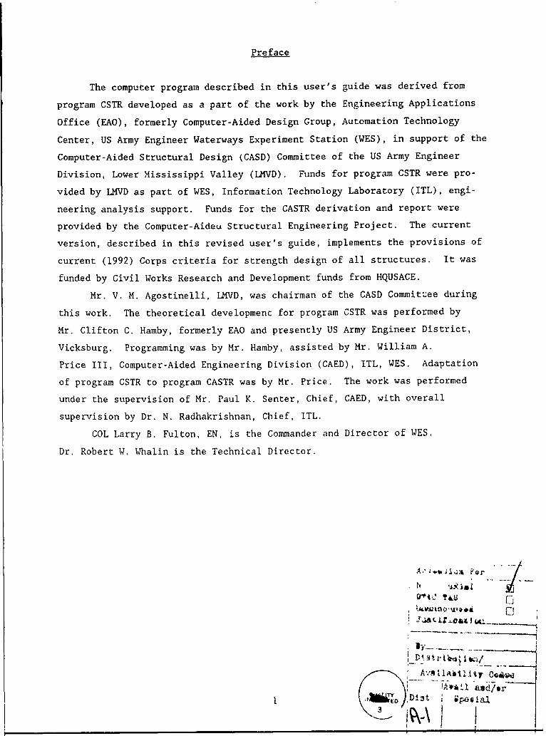
ELECTRONIC COMPUTER PROGRAM ABSTRACT
TITLE OF PROGRAMUser's Guide for Concrete Strength Investi- PROGRAM NO.
gation and Design (CASTR) in Accordance with ACI 318-89 1 713-F3-RO067PREPARING AGENCYUS Army Engineer Waterways Experiment Station, InformationTechnology Laboratory, 3909 Halls Ferry Road. Vicksburg. MS 39180-6199AUTHOR(S) DATE PROGRAM COMPLETED STATUS OF PROGRAMC. C. Hamby (CELMK-ED-DN) and PHASE " STAGEW. A. Price III (CEWES-IM-DA) October 1985 Operational
A. PURPOSE OF PROGRAM
To perform investigation or design of concrete beams or colums in accordancewith ACI Code 318.
B. PROGRAM SPECIFICATIONS
Written in Microsoft FORTRAN using the Graphics Compatibility System (GCS) 2ndC-scape I/0. The CORPS time-sharing library file nane is X0067.
C. METHODS
Strength analysis for investigation or design of rectangular cross sections ofstructure subjected to axial load plus uniaxial flexure. Analysis is based onthe rectangular stress b]ock approximation described in Section 10.2.7 ofACI 138-89.
D. EQUIPMENT DETAILS
In timesharing, Tektronix 4014 terminal on a microcomputer, a graphics videocard is required.
E. INPUT-OUTPUT
Input is interactive or from a data file; output is to a Tektronix 4014 graphicsterminal from timesharing.
F. ADDITIONAL REMARKS
Input data are prepared the same as for program 713-F3-RO 066, "CSTR- oncreteStrength Investigation and Design of Hydraulic Structures (X0066)." Differencesbetween the two programs lie only in the stress block depth and otherparameters. Call WES, (601) 634-2300, for more information.
I
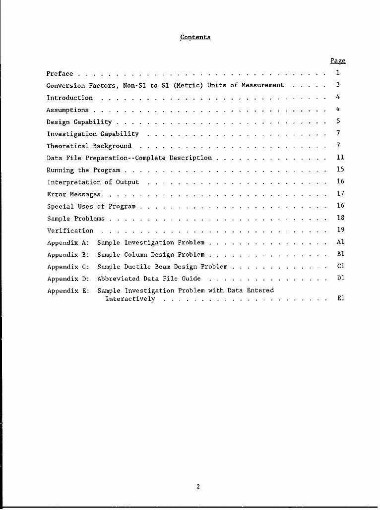
Preface
The computer program described in this user's guide was derived from
program CSTR developed as a part of the work by the Engineering Applications
Office (EAO), formerly Computer-Aided Design Group, Automation Technology
Center, US Army Engineer Waterways Experiment Station (WES), in support of the
Computer-Aided Structural Design (CASD) Committee of the US Army Engineer
Division, Lower Mississippi Valley (LVD). Funds for program CSTR were pro-
vided by LMVD as part of WES, Information Technology Laboratory (ITL), engi-
neering analysis support. Funds for the CASTR derivation and report were
provided by the Computer-Aideu Structural Engineering Project. The current
version, described in this revised user's guide, implements the provisions of
current (1992) Corps criteria for strength design of all structures. It was
funded by Civil Works Research and Development funds from HQUSACE.
Mr. V. M. Agostinelli, LMVD, was chairman of the CASD Committee during
this work. The theoretical development for program CSTR was performed by
Mr. Clifton C. Hamby, formerly EAO and presently US Army Engineer District,
Vicksburg. Programming was by Mr. Hamby, assisted by Mr. William A.
Price III, Computer-Aided Engineering Division (CAED), ITL, WES. Adaptation
of program CSTR to program CASTR was by Mr. Price. The work was performed
under the supervision of Mr. Paul K. Senter, Chief, CAED, with overall
supervision by Dr. N. Radhakrishnan, Chief, ITL.
COL Larry B. Fulton, EN, is the Commander and Director of WES.
Dr. Robert W. Whalin is the Technical Director.
iDist ip*30gaJ41-\c J
Contents
Page
Preface ................................... 1
Conversion Factors, Non-SI to SI (Metric) Units of Measurement ....... 3
Introduction................................4
Assumptions. ...............................
Design Capability .............................. 5
Investigation Capability...........................7
Theoretical Background............................7
Data File Preparation- -Complete Description. ................ 11
Running the Program ............................. 15
Interpretation of Output...........................16
Error Messages...............................17
Special Uses of Program ............................ 16
Sample Problems ............................... 18
Verification................................19
Appendix A: Sample Investigation Problem. ................. Al
Appendix B: Sample Column Design Problem. ................. Bl
Appendix C: Sample Ductile Beam Design Problem. .............. Cl
Appendix D: Abbreviated Data File Guide .................. Dl
Appendix E: Sample Investigation Problem with Data EnteredInteractively ........................ El
2
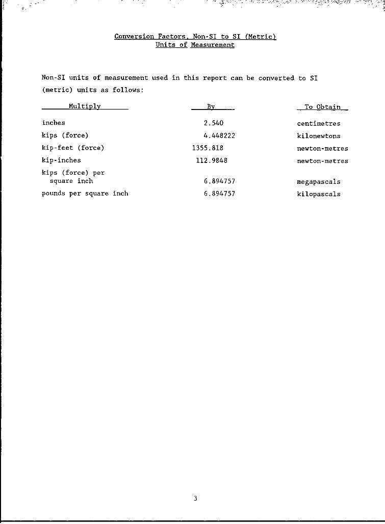
Conversion Factors, Non-SI to SI (Metric)Units of Measurement
Non-SI units of measurement used in this report can be converted to SI
(metric) units as follows:
Multiply By To Obtain
inches 2.540 centimetres
kips (force) 4.448222 kilonewtons
kip-feet (force) 1355.818 newton-metres
kip-inches 112.9848 newton-metres
kips (force) persquare inch 6.894757 megapascals
pounds per square inch 6.894757 kilopascals
3

USER'S GUIDE FOR CONCRETE STRENGTH INVESTIGATION AND
DESIGN (CASTR) IN ACCORDANCE WITH ACI 318-89*
Introduction
1. A computer program, Program CASTR, has been developed by the US Army
Engineer Waterways Experiment Station (WES) Information Technology Laboratory,
formerly Automation Technology Center, that can be used for design of or
investigation of rectangular concrete members by the strength design method
described in Section 10.2 of ACI Code 318-89.** The program utilizes a gener-
alized equation to obtain the axial force and moment capacity of any rectangu-
lar concrete section, reinforced or not, in any pattern (paragraph 13). This
approach allows for solution of a wide variety of problems and loadings, such
as singly or doubly reinforced beams, columns, beam-columns, teiision members,
etc. It is equally applicable to hydraulic structures and to structures not
subject to hydraulic action.
Assumptions
2. The fundamental assumptions used in the development of program CASTR
are summarized below. More details on these assumptions are included in para-
graphs 10 through 16. Figure 1 is provided to further complement the follow-
ing discussions.
a. The cross section is rectangular.
b. The reinforcement may be in any general pattern with no more
than 20 rows of steel.
C.. The loading may consist of a uniaxial moment and an axial load.The axial load can be tension, compression, or zero.
d. ACI 318-89 criteria on stress and strain are used to compute
moment and load capacities.
e. Reinforcement, in investigation or design, is assumed to becapable of developing stresses up to Fy. The user's attention
This edition of the User's guide applies to programs dated 1991/09/25 or
later. Usage for hydraulic structures should be in accordance with"Strength Design for Reinforced Concrete Hydraulic Structures." Engineer
Manual 1110-2-2104 (Headquarters, Department of the Army, 1992).American Concrete Institute, "Building Code Requirements for Reinforced
Concrete (ACI 318-89)."
PU
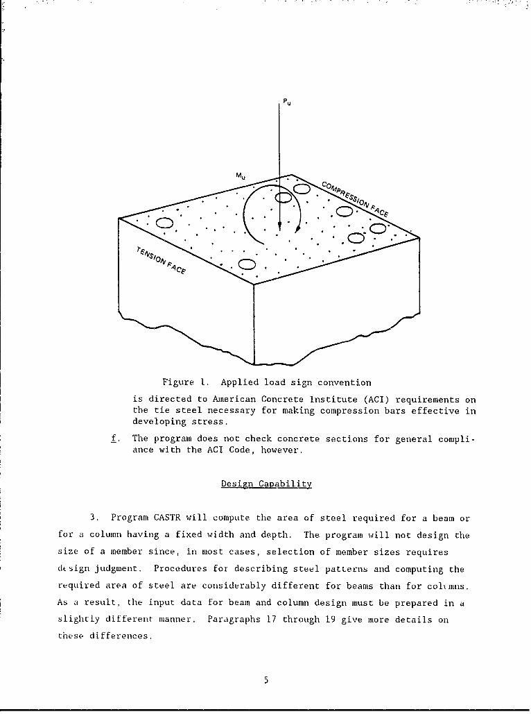
Figure 1. Applied load sign convention
is directed to American Concrete Institute (ACI) requirements onthe tie steel necessary for making compression bars effective indeveloping stress.
f. The program does not check concrete sections for general compli-ance with the ACI Code, however.
Design Capability
3. Program CASTR will compute the area of steel required for a beam or
for a column having a fixed width and depth. The program will not design the
size of a member since, in most cases, selection of member sizes requires
dLsign judgment. Procedures for describing steel patterns and computing the
required area of steel are considerably different for beams than for colminns.
As a result, the input data for beam and column design must be prepared in a
slightly different manner. Paragraphs 17 through 19 give more details on
these differences.
5

Beams
4. In beams, bars are usually defined as rows of tension and compres-
sion steel with ductility also an important consideration. Therefore, for
beam design the user is required to describe spacing criteria for tension
steel, spacing criteria for compression steel, and limits on steel ratios.
CASTR checks the need for tension steel and adds what is required, beginning
with the outermost layer, progressing inward (Figure 2). Likewise, the need
for compression steel is examined and added, if required, progressing from
outer to inner layers. A sufficient amount of compression steel is added to
satisfy steel ratio limits on tension steel (0.75 Pb, for example).
• ' MPRESSION LA YERS
T ~ADDED AS PEI7URED* ASE0
"ALL BARSINCREASED' . ( AS REQUIRED )
TENSION LA YERS0 0 0ADDED AS REOUIRED
_ NOTE *AN ADDITIONAL LAYER IS REQUIRED WHEN ALL BARSIN ONE LAYER HAVE REACHED THEIR MAXIMUM SIZE.
BEAM DESIGN COLUMN DESIGN
Figure 2. Reinforcement design procedure
Columns
5. In column design, bars are rarely described as being in tension or
compression layers; rather, all bars are described in a set pattern. Also,
since ductility is normally not a consideration in column design, the user is
re(quired to describe a desired bar pattern a..J the miiaim u acceptable bar
size. The program then computes the size of bars with the described pattern
necessary to carry the loads. Slenderness effects are not considered and bars
are assumed to be tied in accordance with the ACI Code.
6
Investigation Capability
6. The capabilities of the program extend beyond design into investiga-
tion checking procedures.
Beams and columns
7. The program makes no distinction between beams and columns with its
investigation procedure. Height and width of a rectangular section, as well
as bar areas and locations, are defined by the user. The program then com-
putes the strength of the section and compares this calculated strength with
applied loads. CASTR displays the strength of a section in the form of an
interaction diagram; therefore, use of this program requires an understanding
of the principles of interaction diagrams. A brief explanation of interaction
diagrams and their use is provided in paragraphs 10 through 16.
Ductility check
8. Limits on steel ratios are normally thought of as a means to ensure
ductile behavior and are discussed herein as checks on ductility. In fact,
steel ratio limits in Corps criteria ensure both ductility and crack control.
When the program is used for investigation purposes, the user must input a
maximum allowable steel ratio. In most cases of beam design and in some case.;
of column design, it is important to stay within this maximum limit; there-
fore, t_- program checks for satisfaction of ACI Code 318 and user-specified
ductility requirements in the described section. In some cases of column
investigation, the user may choose to ignore the program's check on ductility,
also maximum steel ratios set by the ACI for columns are not checked.
Theoretical Background
9. Making full use of program CASTR requires an understanding of
interaction diagrams and how they are used.
Interaction diagrams
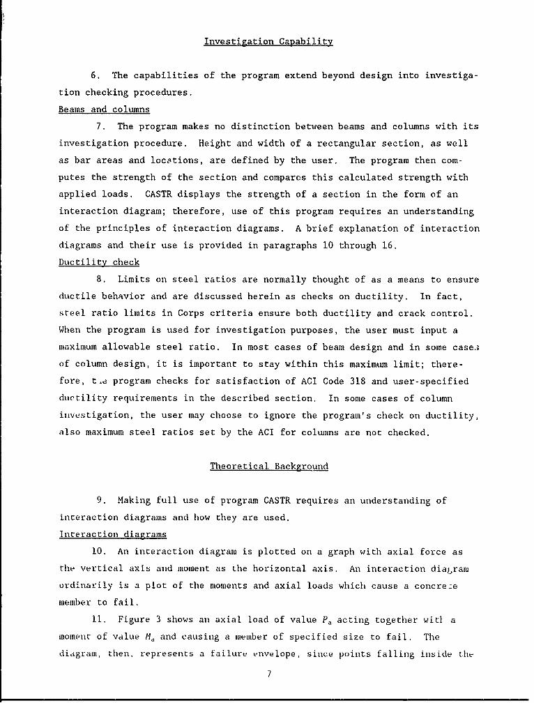
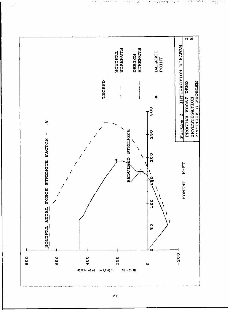
10. An interaction diagram is plotted on a graph with axial force as
the vertical axis and moment as the horizontal axis. An interaction diagram
ordinarily is a plot of the moments and axial loads which cause a concrece
member to fail.
11. Figure 3 shows an axial load of value Pa acting together witi a
moment of value M, and causing a member of specified size to fail. The
diagram, then, represents a failure envelope, since points falling inside the
7
curve do not cause failure and those falling on or outside the curve do cause
failure.* A reinforced concrete membei is made of two differently behaving
,aterials, steel and concrete, and the equations which define failure depend
on whether the steel yields or the concrete crushes. The tension control
range represents those axial loads and moments which cause the section to fail
because the steel yields (Figure 3). Likewise, the compression control range
represents those combinations of axial loads and moments which cause the mem-
ber to fail by crushing of the concrete. The axial load and moment wyich
cause simultaneous failure of steel and concrete is the balance point.
CCI
AXIAL P
LOAD
BALANCE POINT
Pa -N ' i
e4INMOMEN T
Figure 3. Interaction diagram
The term failure is used in discussion; however, failure is actuallydefined by the ACI as occurring when concrete strains reach 0.003.
8
Stress-strain assumptions
12. Strains are zero at the neutral axis and vary linearly from the
neutral axis to a maximum value of 0.003 at the extreme fiber. The
compressive stresses in the beam are approximated by a rectangular stress
block 0.85 fE in magnitude and f31G high.
Usable load and moment
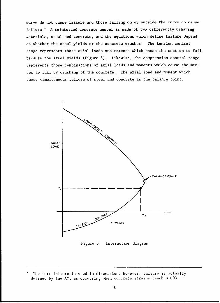
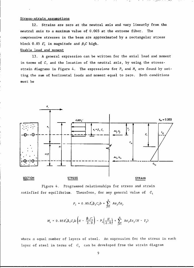
13. A general expression can be written for the axial load and moment
in terms of C, and the location of the neutral axis, by using the stress-
strain diagrams in Figure 4. The expressions for Pi and M, are found by set-
ting the sum of horizontal loads and moment equal to zero. Both conditions
must be
Pt
oa85f" = 0.003
CC,
• Asnfsn nn
H
Pi O,5f'pzC b EAs,,fs,,
H72
where F equal number of layers of steel. An expression for the stress in each
layer of steel in terms of C can be developed from the strain diagram
9
fs 4 = (CE - Ec -fY fj5
14. The general expressions for Pi and M, shown in the preceding pare-
graph can generate an interaction diagram by iterating the value of C from
near zero to near infinity and computing the values of P, and M, for each
value of Ci. This, in effect, computes the full range of load and moment
capacities of the section with all possible positions of the neutral axis.
Ductility
15. The ACI Code requires that the steel ratio cannot exceed 0 .7 5Pb
for members with axial load less than 0.1Of' bh. Designers may choose toc
place more stringent limitations on maximum steel ratios, using input data
!Lem PEROB. During the usual design process, if the tension steel required
exceeds limitations on steel ratioL compression steel can be added, or the
beam size increased until the maximum tensile steel ratio limit is satisfied.
Increasing the beam size is usually the preferred procedure. Some designers
prefer to size the reinforcing steel and check the maximum steel limit with a
special load case neglecting any axial compression. The computer program can-
not change the concrete dimensions, so it will add compression steel if the
tension steel required exceeds the user's limitation on the steel ratio. This
addition of a sufficient amount of compression steel is made so that the por-
tion of tension steel resisted by concrete compressive stresses does not
exceed the specified upper limits on steel ratio (paragraph 10.3.3, ACI Code
318-89). For convenience, CASTR computes and prints the minimum size beam
depth which can be used without compression steel. Columns are designed with-
out regard for ductility.
Iterating to a solution
16. Paragraph 13 describes how an interaction diagram can be generated
for a given problem. CASTR designs begin with a very small amount of steel
and generates an interaction diagram. If the loading falls outside the enve-
lope created by the diagram, steel areas are increased and a new diagram is
generated. This process continues until the diagram exceeds loadings and, in
the case of beams, until steel ratio limits are satisfied.
10
Data File Preparation--Complete Description
17. The data file must be prepared in advance by using line numbers
with three digits. One blank space must follow the line number; data values
should be separated by one or more blanks. Lines may not be continued. Units
are kips and inches, except that applied moments (RMU) are in kip-feet.
Appendix D contains a summary of the information in this paragraph.
Fixed data
18. The first four lines of the data file may be thought of as fixed
data since these lines are u.,ed only once in a data file.
a. Job title. Two lines of job title must be first in the file.
Each of the two lines must have a line number, a blank space,
and up to 30 characters of job title.
b. Mode line.
LN MODE
where
LN Line Number
MODE I for investigation (paragraph 7)
2 for column design (paragraph 5)
3 for beam design (paragraph 4)
Note: See paragraph 31
c. Properties line.
LN FC FY PEROB
where
LN = Line Number
FC = concrete ultimate strength f' , ksi
FY = steel yield strength fy, ksi
PEROB = limiting ratio of actual reinforcement to balance
reinforcement. Use only when MODE = 1 (investi-gation) or 3 (beam design). It must be omitted
when MODE = 2 . Structures not subject to
hydraulic action generally follow ACI 318, except
that Corps of Engineers' conduits with large
axial force should use the value 0.375. Struc-tures subject to hydraulic action must comply
with maximum tension reinforcement as stated in
Engineer Manual "Strength Design for ReinforcedConcrete Hydraulic Structures:"* See also para-
graph 15 of this user guide.
Headquarters, Department of the Army. "Streingch Design for ReinforcedConcrete Hydraulic Structures," Engineer Manual 1992, Washington DC.
11
Note that very little economy is realized by using values greater than 4.375
and that larger values may lead to constructibility problems.
For singly-reinforced flexural members, and for members subject to com-
)ined flexure and compressive axial load when the axial load strength qSPn is
less than the smaller of 0.10fe A8 or OPb, the ratio of tension reinforce-
ment p provided shall cunform to the following.
Recommended limit = 0.25 Pb
Maximum permitted upper limit not requiring special study or investiga-
tion - 0.375 Pb, will require consideration of serviceability, constructi-
bility, and economy.
Maximum permitted upper limit when excessive deflections are not pre-
dicted when using the method specified in ACI 318 or other methods that pre-
dict deformations in substantial agreement with the results of comprehensive
tests = 0.50 Pb.
Reinforcement ratios above 0.5 Pb shall only be permitted if a detailed
investigation of serviceability requirements, including computation of deflec-
tions, is conducted in consultation with and approved by CECW-ED. Under no
circumstance shall the reinforcement ratio exceed 0.75 Pb.
Use of compression reinforcement shall be in accordance with provisions
of ACI 318.
Section data
19. Section data sets may be repeated without limit, in order to exam-
ine as many sections as desired.
a. Section title line. One line, with a line number, one blank
space, then up to 30 characters of section and/or load case
title.
b. Geometry line.
LN B H
where
LN = Line Number
B = section width, in.
H = section total height, in.
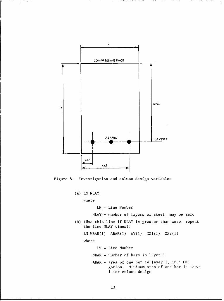
c. Reinforcing lines. Refer to Figure 5 for reinforcement
descriptions of investigation problems and column design;
refer to Figure 6 for beam design.
(1) If MODE = 1 for investigation or 2 for column design.
12
COMPRESSIVE FACE
A Y1I)
H
. ABA R{)4BAR1-) LA YER I
xx2
Figure 5. Investigation and column design variables
(a) LN NLAY
where
LN = Line Number
NLAY = number of layers of steel, may be zero
(b) (Use this line if NLAY is greater than zero, repeatthe line NLAY times):
LN NBAR(I) ABAR(I) AY(I) XXI(I) XX2(I)
where
LN = Line Number
NBAR = number of bars in layer I
ABAR = area of one bar in layer I, in.2 for
gation. Minimum area of one bar ii layerI for column design
13
X2COM
X2CM .- COMPRESSIVE FACE
, iY C O M
I SCL AY
I YTENH LOAD IS A T
+ CENTER OF
ATEN SECTION
i I ,STLAY
S TLLAY
,A Y
X I TEN
X2TEN
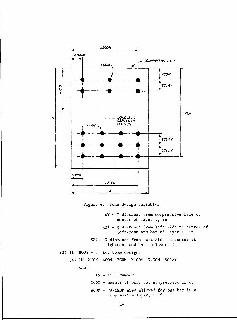
Figure 6. Beam design variables
AY = Y distance from compressive face tocenter of layer I, in.
XXI = X distance from left side to center of
left-most end bar of layer I, in.
XX2 = X distance from left side to center of
rightmost end bar in layer, in.
(2) If MODE = 3 for beam design:
(a) LN NCOM ACOM YCOM XCOM X2COM SCLAY
where
LN = Line Number
NCOM = number of bars per compressive layer
ACOM = maximum area allowed for one bar in a
compressive layer, in.2
14
YCOM = Y distance from compressive face to thecenter of the outermost (top) layer, in.
XlCOM - X distance from left side to the center ofthe leftmost end bar in a layer of
compressive steel, in.
X2COM - X distance from the left side to the of therightmost end bar in a layer of compressivesteel, in.
SCLAY - center-to-center spacing (Y-direction)
between layers of compressive steel, in.
(b) LN NTEN ATEN YTEN XITEN X2TEN STLAY
where these tensile steel descriptions are similar to thecorresponding descriptions for compressive steel insubparagraph (a) on preceding page.
d. Load line.
LN PU RMU
where
LN - Line Number
PU - factored axial load, kips, located at B/2, H/2,compression +
RMU - factored bending moment about the beam centerline,kip-feet, including the moment induced by PU not actu-ally located at H12. Always entered as a positivevalue, tending to cause compression in the face so con-sidered when defining the reinforcing steel. Rememberthe code requirements for minimum moment when the theo-retical moment is zero.
Running the Program
20. The following information is a step-by-step guide for preparing a
data file and program operation.
a. Begin the program:
(1) Honeywell computers: (* prompt)
*FRN WESLIB/CORPS/XO066,R
(2) CDC computers: (/ prompt)
/OLD,CORPS/UN=CECELB
/BEGIN,,CORPS,X0066
(3) Harris computers: (no prompt)
*CORPS,X0066
b. Enter the data file name when requesced. This must be in allcapital letters for the microcomputer version.
15
c. When the bell sounds, the program will pause for the user to makeh-rd copies or notes of what is currently displayed, then pressthe "RETURN" key to continue.
d. The message "END OF DATA" indicates that all of the data havebeen processed without file read errors. Refer to paragraph 25for an explanation of error messages.
Interpretation of Output
21. Output interpretation and investigation following a program is as
vital to its success as the preliminaries for the actual run.
Investigation (MODE = 1)
22. Beginning with this paragraph and through paragraph 24, the designa-
tion of "figure" applies to computer output Figures 1 and 2.
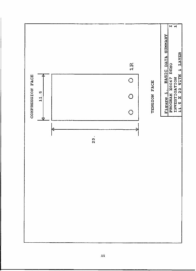
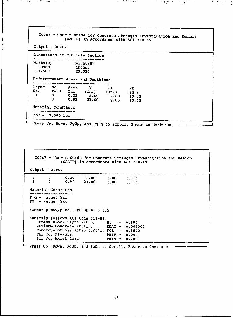
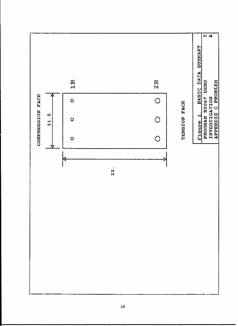
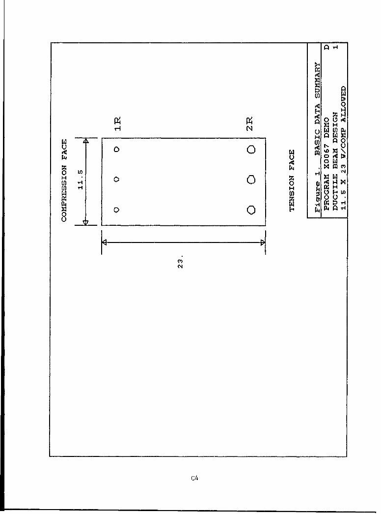
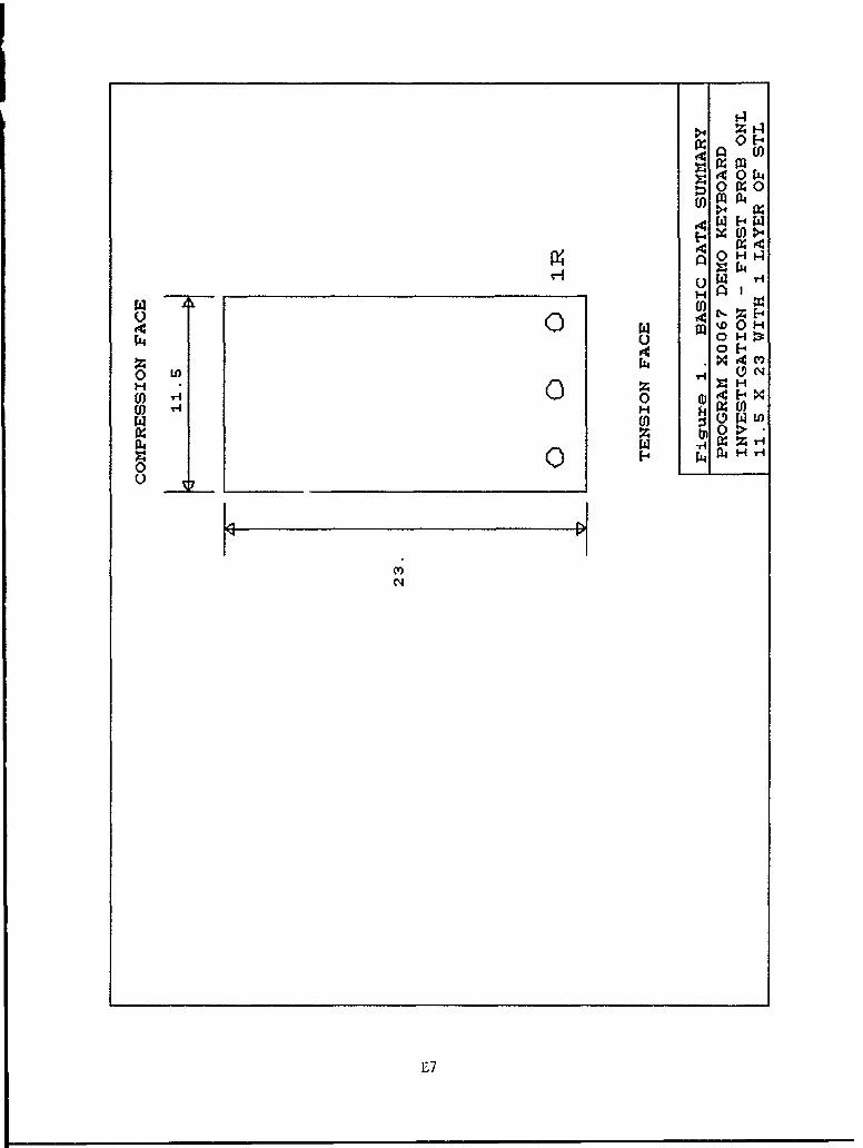
a. Figure 1 includes tables of basic data and a picture of the sec-
tion. The analysis parameters P1, fmax' f./f
Oaxial ' and Oflexure are listed.
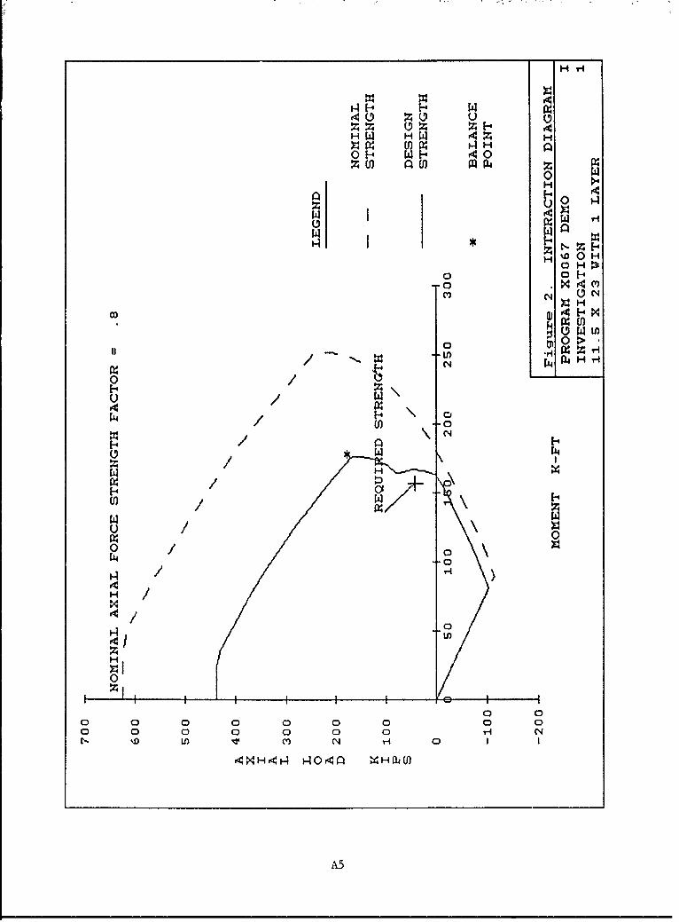
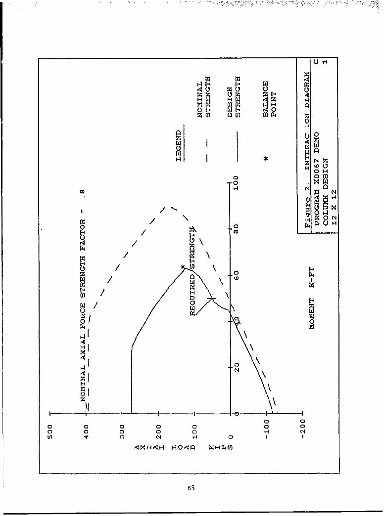
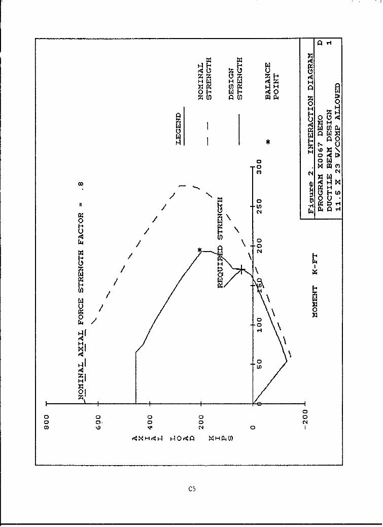
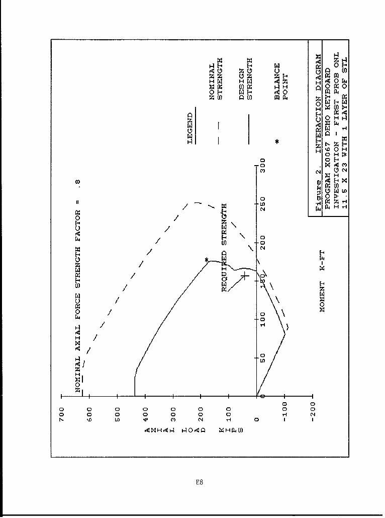
b. Figure 2:
(1) Two P/M interaction curves, one with the capacity reductionfactor PHI included ("DESIGN STRENGTH") and one without("NOMINAL STRENGTH"). The nominal strength curve is anno-tated with the axial force strength upper limit value. Thebalance point is indicated with an *. The 0 value used iscomputed from the 0 values shown, in accordance withACI 318-89, para. 9.3.2.
(2) PU, RMU, and the PHI factor used for the given loading.
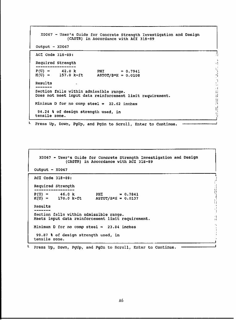
(3) Pass/fail message relating to the ability of the section toresist the applied PU and RMU, with PHI included. The ad-missible range is assumed to be within the "DESIGN STRENGTH"curve, without regard for the reinforcement ratio limitrequirement PEROB. Ductility satisfaction or failure isreported by a message.
(4) The percentage of permissible design strength used by thefactored applied loading is reported in a message, along witha message describing the type of failure expected at thegiven eccentricity.
Column design (MODE = 2)
23. Column design is composed of two figures as described below.
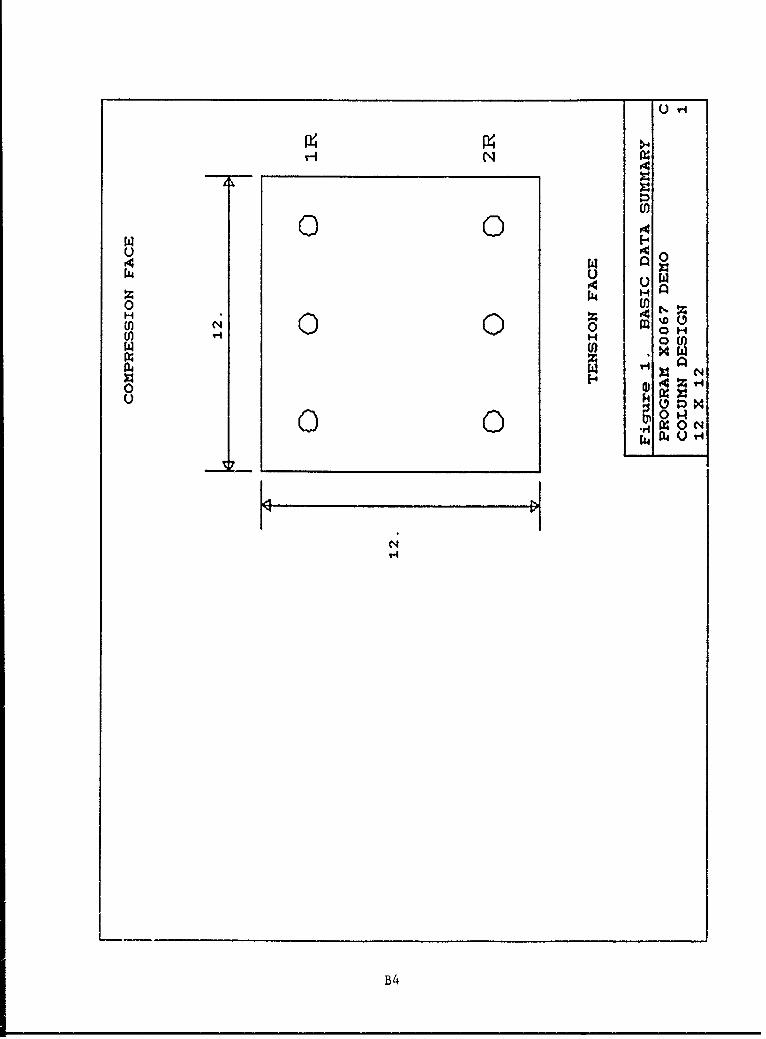
a. Figure 1: Tables of basic data and picture of final section asdesigned. The bar areas in the table of "Reinforcement Areas andPositions" are as designed, not the minimum values in the datainput. Analysis parameters used are listed.
16
b. Figure 2: Same as for investigation, plus the minimum effectivedepth required with the input value of B to yield an acceptablesection without compressive reinforcement.
Beam design (MODE - 3)
24. Beam design, as in column design, is shown by figures made up of data
tables as listed:
a. Figure 1: Tables of basic data and picture of final section asdesigned. The bar areas in the table of "Reinforcement Areas andPositions" are as designed and not the limiting values in thedata file. Gross steel ratios for tensile and for compressivesteel are listed.
b. Figure 2: Same as for Column Design except that a message on the
right side of the figure shows compliance with the reinforcementrequirement PEROB.
Error Messages
25. Listed below are possible error messages and a brief explanation of
each one:
a. The message "## DATA ERROR ### LAST LINE WAS nnn" means one ofseveral things:
(1) Improper value for MODE, in which case nnn will be the linenumber of the MODE line in the data file.
(2) incomplete data file, one item or an entire line missing, inwhich case nnn will be the number of the last line in thefile.
(3) A decimal point used after a data item name beginning withthe letters M or N, in which case nnn will be the number ofthe line containing the improper decimal point.
(4) A misplaced Job Name or Section Name line, in which case nnnwill be the number of the misplaced Name line.
b. If MODE = 2 for column design, a message "A REINF. DESIGN CANNOTBE FOUND--COLUMN SIZE MUST BE INCREASED" means that the bar size
needed exceeded 100 in.2*
c. If MODE - 3 for ductile beam design, a message "A REINF. DESIGNCANNOT BE FOUND--EITHER BEAM SIZE OR BAR SIZE MUST BE INCREASED"means that so many layers of reinforcing containing bars of thespecified quantity and maximum size were needed that the tensileand compressive reinforcing patterns overlapped.
A table of fitors for converting non-SI units of measurement to SI,mletric) units is presented on page 3.
17
Special Use.: of Program
26. The program is versatile in its uses and specific areas are described
in the following paragraphs. Call the authors for information on advanced
research capabilities.
Slab design
27. Slabs may be designed by inputting a 12.0-in.-wide strip.
Unreinforced section
28. An unreinforced section can be analyzed by inputting NLAY - 0 in the
reinforcement data and omitting bar descriptions.
Nonductile beam design
29. If the user wants to design a beam forcing the design to be singly
reinforced without regard for the steel ratio limit PEROB the column design
procedure can be used. Reinforcement can be described as layers only in the
tensile face.
Special plot file output
30. The plot coordinate values of either of the two moment vs. axial
force interaction diagrams shown in the output screen "Fig. 2 INTERACTION
DIAGRAM" can be written out to a file when desired. The file will be ASCII,
with the format as shown below.
First line: No. of points in curve (50), in the Fortran format 15.
Following lines: Coordinates of one point, moment and then force, in
the Fortran format 2E14.4. There will be 50 such lines. The first such line
will contain the maximum negative force value point; the last one will contain
the maximum positive force value point. Thus, the force values will all be
different but the same moment \alue may appear twice, once with a negative
force and once with a positive force.
To get such a plot file, make the value used for section width, B, negative.
Computations will use the value as positive and the negative sign will trigger
two questions, one for a name to be given the file and the other to select the
curve whose values are to be written to the file ("Nominal Strength" without
phi included or "Design Strength" with phi included).
Research usage
31. Special values can be used for the input value of MODE on the mode
data line as described in paragraph 18.b so as to get special variations of
the stress block parameters, in accordance with the following table. The term
"ETL" refers to ETL's 1110-2-265 dated 1981 and 1110-2-312 dated March 1988.
18
"ETL" analysis will yield the same design strength along all points on the
interaction diagram as would Working Stress Analysis. The bottom of the first
output screen will display a table showing the actual stress block parameters
used.
Mode action
-9 as described for MODE = 1, except ETL parameters-8 as described for MODE = 2, except ETL parameters-7 as described for MODE - 3, except ETL parametersI as described for MODE - 1 (using ACI parameters)2 as described for MODE - 2 (using ACI parameters)3 as described for MODE - 3 (using ACI parameters)
21 as described for MODE - I (see footnote)22 as desci'ibed for MODE - 2 (see footnote)23 as described for MODE - 3 (see footnote)
footnote: an additional line of data will be needed, after the properties
data line described in paragraph 18c:
LN BI EMAX FCR PMAXF PHIF PHIA
where
LN = Line Number
BI - Depth of stress block as a fraction of the depth of thecompression face (beta). See section 10.2.7.3 ofACI 318-89.
EMAX - Allowable strain (0.003 in ACI, 0.0015 in ETL)
FCR - Stress block stress as a fraction of ultimate (0.85 in ACI &ETL)
PMAXF - Limiting strength of column due to axial load (0.8 in ACI,0.7 in ETL)
PHIF - Phi value for flexure (0.9 in ACI and ETL)
PHIA = Phi value for axial force (0.7 in ACI & ET)
Sample Problems
32. A sample investigation problem is presented in Appendix A, a sample
column design problem is presented in Appendix B, and a sample beam problem is
presented in Appendix C. An abbreviated description of a data file prepara-
tion is included in Appendix D.
Verification
33. The parent program, X0066, was checked thoroughly with hand compu-
tations. Since the only differences between X0066 axid X0067 are as shown
19
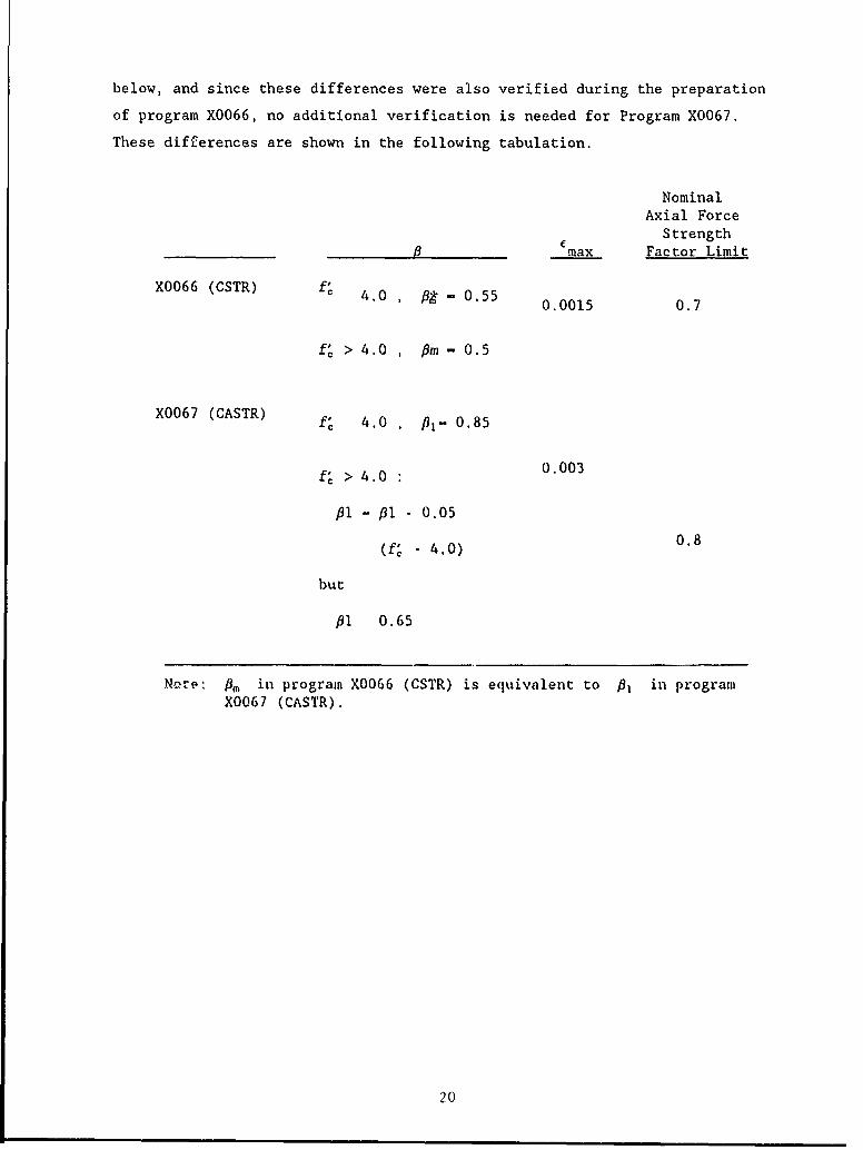
below, and since these differences were also verified during the preparation
of program X0066, no additional verification is needed for Program X0067.
These differences are shown in the following tabulation.
NominalAxial ForceStrength
_6 max Factor Limit
X0066 (CSTR) 0.554.0 0. 0015 0.7
f' > 4.0 , - 0.5
X0067 (CASTR) f" 4.0 , pl- 0.85
f' > 4.0 0.003
f1 - fl - 0.05
(f' - 4.0) 0.8
but
fl 0.65
Nore: mf in program X0066 (CSTR) is equivalent to f1 in programX0067 (CASTR).
20
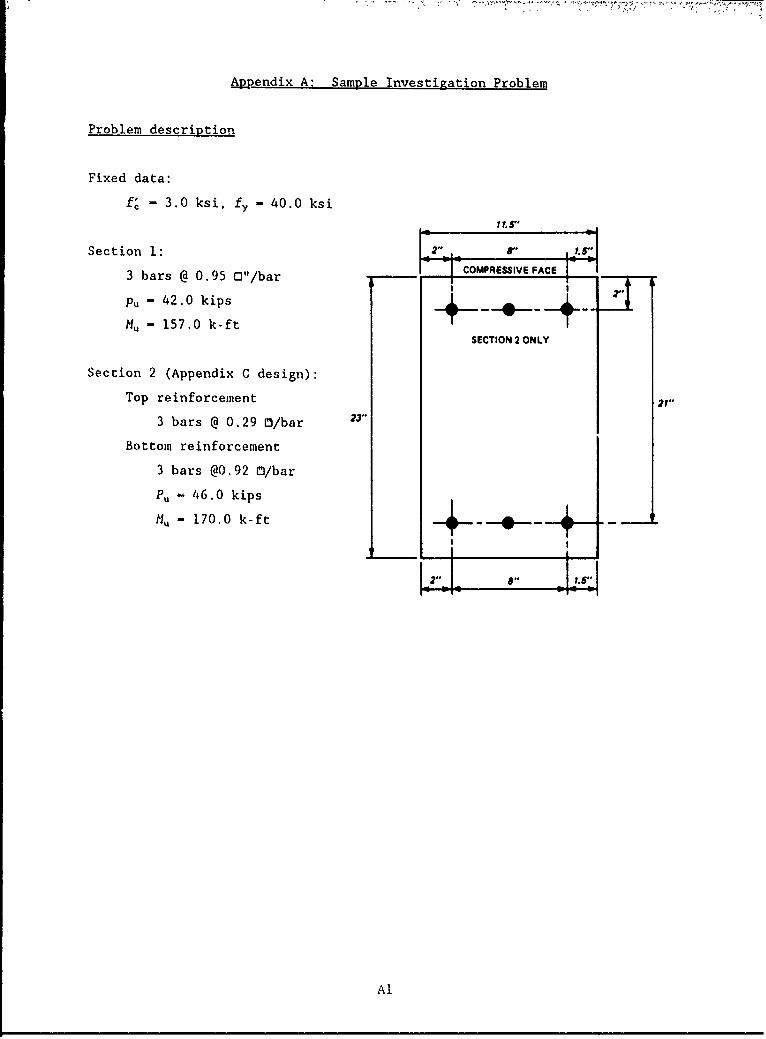
Appendix A: Sample Investigation Problem
Problem description
Fixed data:
f, - 3.0 ksi, fy - 40.0 ksi
Section 1: Jr. i?
3 bars @ 0.95 O"/bar -COMPREIVE FACE2
Pu - 42.0 kips 4 _
M. - 157.0 k-ftSECTION 2 ONLY
Section 2 (Appendix C design):
Top reinforcement 21"
3 bars @ 0.29 0/bar 23"
Bottom reinforcement
3 bars @0.92 0/bar
Pu - 46.0 kips
M. - 170.0 k-ft -- _..._-.__
Al
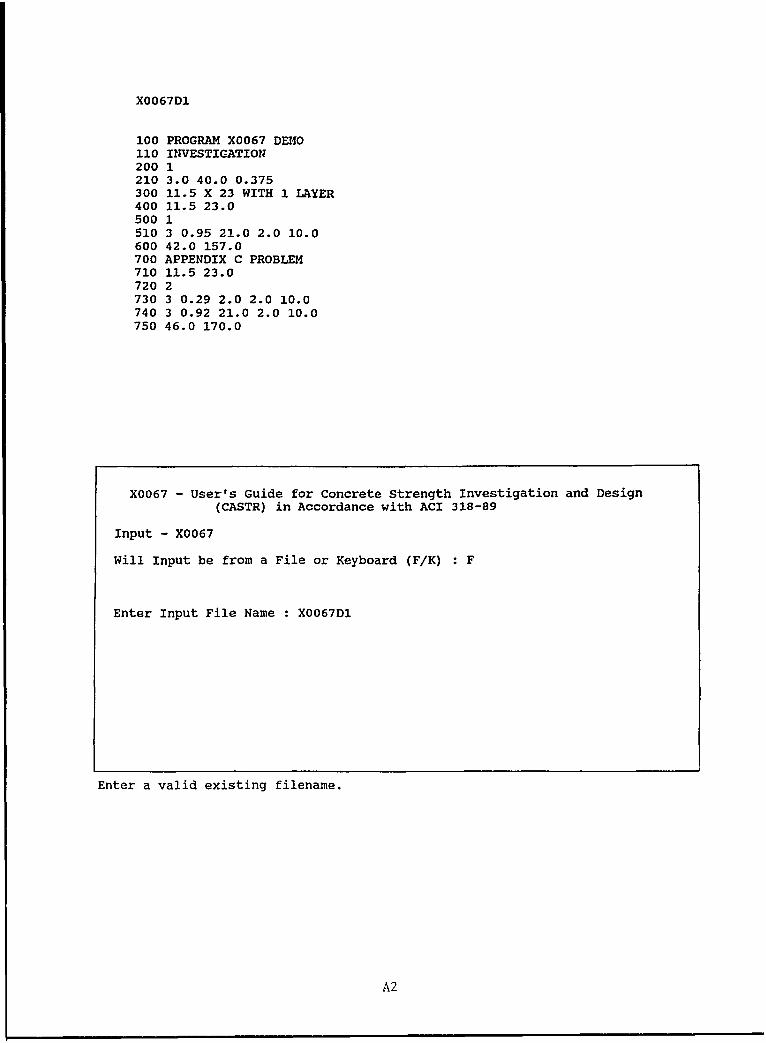
X0067D1
100 PROGRAM X0067 DE40110 INVESTIGATION200 1210 3.0 40.0 0.375300 11.5 X 23 WITH 1 LAYER400 11.5 23.0500 1510 3 0.95 21.0 2.0 10.0600 42.0 157.0700 APPENDIX C PROBLEM710 11.5 23.0720 2730 3 0.29 2.0 2.0 10.0740 3 0.92 21.0 2.0 10.0750 46.0 170.0
X0067 - User's Guide for Concrete Strength Investigation and Design
(CASTR) in Accordance with ACI 318-89
Input - X0067
Will Input be from a File or Keyboard (F/K) : F
Enter Input File Name : X0067D1
Enter a valid existing filename.
A2
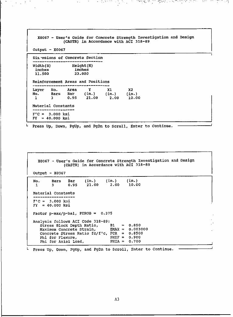
X0067 - User's Guide for Concrete Strength Investigation and Design
(CASTR) in Accordance with ACI 318-89
Output - X0067
Din.'nsions of Concrete Section
Width(B) Height(H)inches inches11.500 23.000
Reinforcement Areas and Positions
Layer No. Area Y X1 X2No. Bars Bar (in.) (in.) (in.)1 3 0.95 21.00 2.00 10.00
Material Constants
F'C = 3.000 ksiFY = 40.000 ksi
L Press Up, Down, PgUp, and PgDn to Scroll, Enter to Continue.
X0067 - User's Guide for Concrete Strength Investigation and Design
(CASTR) in Accordance with ACI 318-89
Output - X0067
No. Bars Bar (in.) (in.) (in.)1 3 0.95 21.00 2.00 10.00
Material Constants
F'C = 3.000 kniFY = 40.000 ksi
Factor p-max/p-bal, PEROB = 0.375
Analysis follows ACI Code 318-89:Stress Block Depth Ratio, B1 = 0.850Maximum Concrete Strain, EMAX = 0.003000Concrete Stress Ratio fc/f'c, FCR = 0.8500Phi for Flexure, PHIF = 0.900Phi for Axial Load, PHIA = 0.700
L Press Up, Down, PgUp, and PgDn to Scroll, Enter to Continue.
A3
r4
H
ZI-
'40 0 OH
z miH X(n i v 0 0 4H M
93 t4 T-~V 4
0
CY,
A4
I-IH '4
H H 14 0
z ) aU)z W
H0t 0 0
HOH
o H
O /H
OD H H N
) / U0p /
IX1 Z/-'44T
'4/4
'4'4
0 i
0 0
0 0 0 0 0 00 0
0 - 0 000,- '
Ui) v' (V) 0NI '4 0 1 1
'4MH'40- L4O'4r X4HN)
A5
X0067 - User's Guide for Concrete Strength Investigation and Design
(CASTR) in Accordance with ACI 318-89
Output - X0067
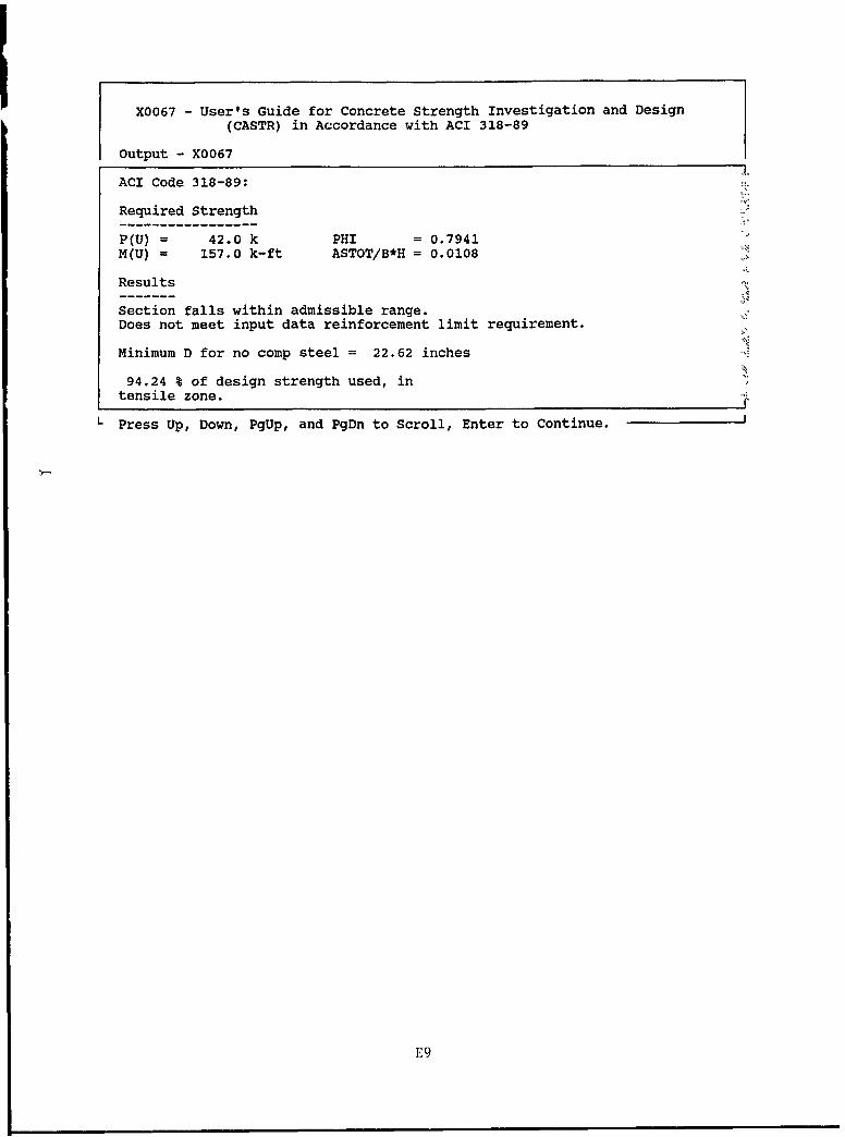
ACI Code 318-89:
Required Strength
P(U) = 42.0 k PHI = 0.7941M(U) = 157.0 k-ft ASTOT/B*H = 0.0108
Results
Section falls within admissible range.
Does not meet input data reinforcement limit requirement.
Minimum D for no comp steel = 22.62 inches
94.24 % of design strength used, intensile zone.
L Press Up, Down, PgUp, and PgDn to Scroll, Enter to Continue.
X0067 - User's Guide for Concrete Strength Investigation and Design(CASTR) in Accordance with ACI 318-89
Output - X0067I.
ACI Code 318-89:
Required Strength
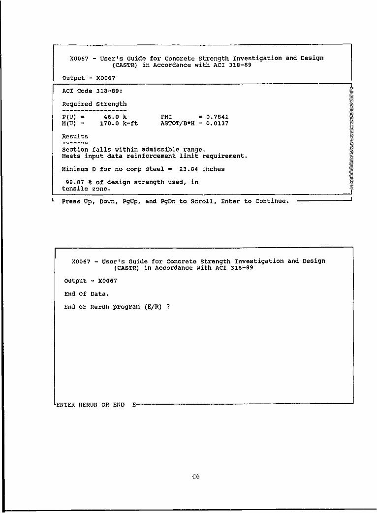
P(U) = 46.0 k PHI = 0.7841M(U) = 170.0 k-ft ASTOT/B*H = 0.0137
Results
Section falls within admissible range.Meets input data reinforcement limit requirement.
Minimum D for no comp steel = 23.84 inches
99.87 % of design strength used, intensile zone.
L Press Up, Down, PgUp, and PgDn to Scroll, Enter to Continue.
A6
X0067 - User's Guide for Concrete Strength Investigation and Design
(CASTR) in Accordance with ACI 318-89
Output - X0067
Dimensions of Concrete Section---------------------------Width(B) Height(H)inches inches11.500 23.000
Reinforcement Areas and Positions------------------------------Layer No. Area Y X1 X2No. Bars Bar (in.) (in.) (in.)1 3 0.29 2.00 2.00 10.002 3 0.92 21.00 2.00 10.00
Material Constants
F'C = 3.000 ksi
L Press Up, Down, PgUp, and PgDn to Scroll, Enter to Continue.
X0067 - User's Guide for Concrete Strength Investigation and Design
(CASTR) in Accordance with ACI 318-89
Output - X0067
1 3 0.29 2.00 2.00 10.002 3 0.92 21.00 2.00 10.00
Material Constants
F'C = 3.000 ksiFY = 40.000 ksi
Factor p-max/p-bal, PEROB = 0.375
Analysis follows ACI Code 318-89:Stress Block Depth Ratio, B1 = 0.850Maximum Concrete Strain, EMAX = 0.003000Concrete Stress Ratio fc/f'c, FCR = 0.8500Phi for Flexure, PHIF = 0.900Phi for Axial Load, PHIA = 0.700
L Press Up, Down, PgUp, and PgDn to Scroll, Enter to Continue.
A7
'4:
0 LfZH N
w U
A8A
z z ZF-zHN HN ,4Z
0OH w H 400U U)o m 0
0
0
IZ 0N0 m
OHH
coN/0 > 0
0) /
NN
H
04.-
4/
i-l
O0 0 00 0 0
A9
X0067 - User's Guide for Concrete Strength Investigation and Design
(CASTR) in Accordance with ACI 318-89
Output - X0067
End Of Data.
End or Rerun program (E/R) ?
-ENTER RERUN OR END E
A10
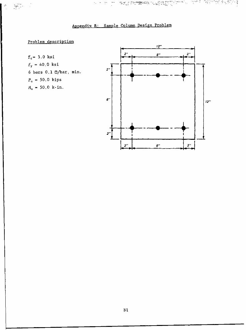
Appendix B: Sample Column Design Problem
Problem description
n 82" 2" !
fc = 3.0 ksi al 2"
fy = 40.0 ksi
6 bars 0.1 O/bar, min. 2"
Pu = 50.0 kips
Mu - 50.0 k-in.
8"12"
2 2 4
Bi
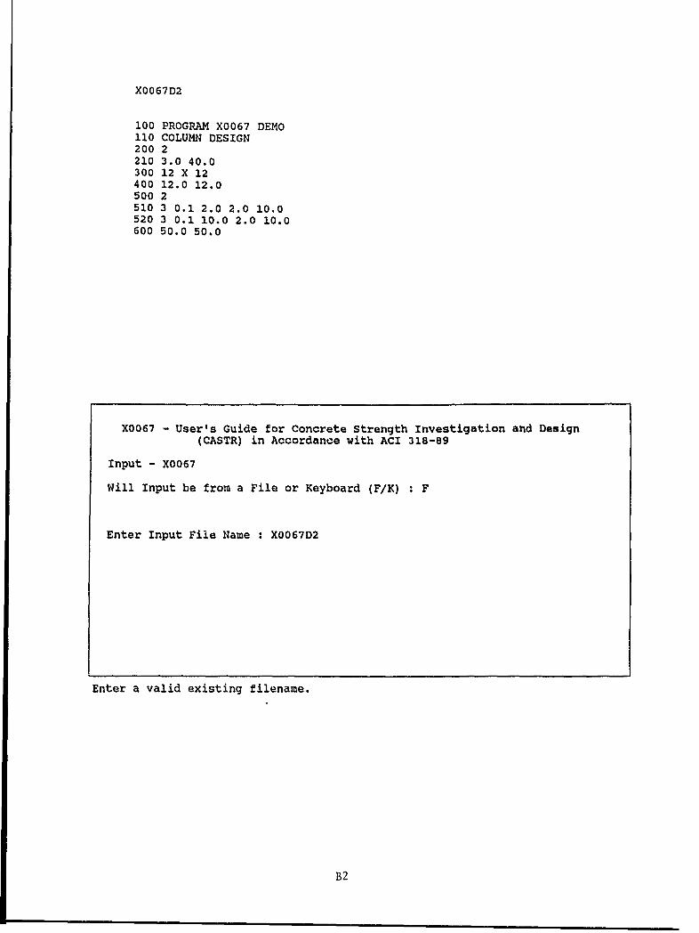
X0067D2
100 PROGRAM X0067 DEMO110 COLUMN DESIGN200 2210 3.0 40.0300 12 X 12400 12.0 12.0500 2510 3 0.1 2.0 2.0 10.0520 3 0.1 10.0 2.0 10.0600 50.0 50.0
X0067 - User's Guide for Concrete Strength Investigation and Design
(CASTR) in Accordance with ACI 318-89
Input - X0067
Will Input be from a File or Keyboard (F/K) : F
Enter Input File Name : X0067D2
Enter a valid existing filename.
B2
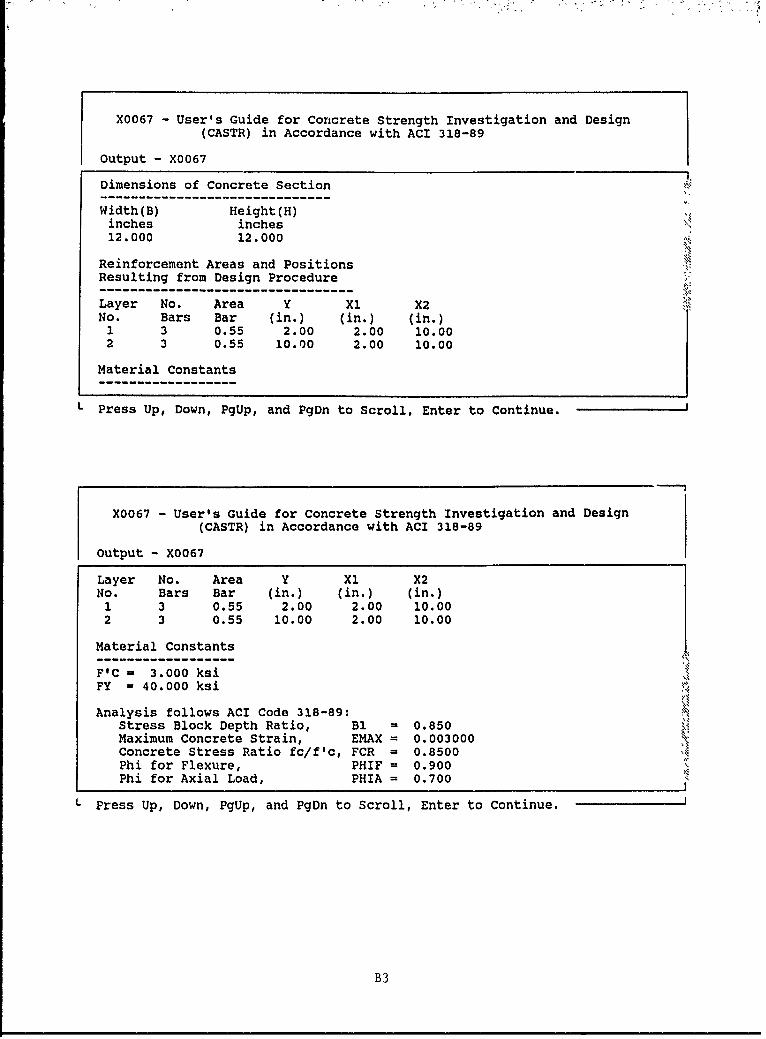
X0067 - User's Guide for Concrete Strength Investigation and Design(CASTR) in Accordance with ACI 318-89
Output - X0067
Dimensions of Concrete Section
Width(B) Height(H)inches inches12.000 12.000
Reinforcement Areas and PositionsResulting from Design Procedure
Layer No. Area Y Xl X2No. Bars Bar (in.) (in.) (in.)1 3 0.55 2.00 2.00 10.002 3 0.55 10.00 2.00 10.00
Material Constants
L Press Up, Down, PgUp, and PgDn to Scroll, Enter to Continue.
X0067 - User's Guide for Concrete Strength Investigation and Design
(CASTR) in Accordance with ACI 318-89
Output - X0067
Layer No. Area Y X1 X2No. Bars Bar (in.) (in.) (in.)1 3 0.55 2.00 2.00 10.002 3 0.55 10.00 2.00 10.00
Material Constants
FIC - 3.000 ksiFY - 40.000 ksi
Analysis follows ACI Code 318-89:Stress Block Depth Ratio, B1 = 0.850Maximum Concrete Strain, EMAX = 0.003000Concrete Stress Ratio fc/f'c, FCR = 0.8500Phi for Flexure, PHIF = 0.900Phi for Axial Load, PHIA = 0.700
L Press Up, Down, PgUp, and PgDn to Scroll, Enter to Continue.
B3
0 0
'4 w0
C14 0 O(n -4 H0)
r40
014-
B4
0 z HHN HN H
zW U)) LTQ0
N Z
H
O 00)0
0o 14 -
1I4 /
/ 0
N/ wWN
001A4
I~9 a
LO v HI
oM4 044 0 0 N 0(0
0 0 0 0 B5
X0067 - User's Guide for Concrete Strength Investigation and Design
(CASTR) in Accordance with ACI 318-89
Output - X0067
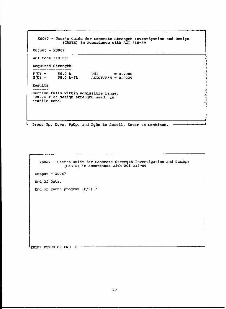
ACI Code 318-89:
Required Strength
P(U) = 50.0 k PHI = 0.7000M(U) = 50.0 k-ft ASTOT/B*H = 0.0229
Results
Section falls within admissible range.98.24 % of design strength used, in
tensile zone.
L Press Up, Down, PgUp, and PgDn to Scroll, Enter Lo Continue.
X0067 - User's Guide for Concrete Strength Investigation and Design
(CASTR) in Accordance with ACI 318-89
Output - X0067
End Of Data.
End or Rerun program (E/R) ?
ENTER RERUN OR END E
B6
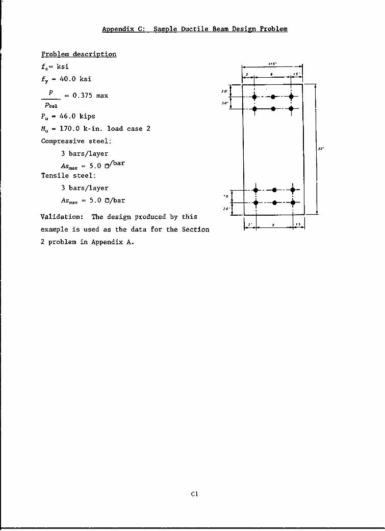
Appendix C: Sample Ductile Beam Design Problem
Problem description
fc= ksi
fy = 40.0 ksi
P =0.375 max 'D--- --2ba .7 -t
Pu = 46.0 kips :
Mu = 170.0 k-in. load case 2
Compressive steel:
3 bars/layer
Asmax = 5.0 O/bar
Tensile steel:
3 bars/layer'0
Asmax = 5.0 /bar _ __20",
Validation: The design produced by this
example is used as the data for the Section
2 problem in Appendix A.
C'
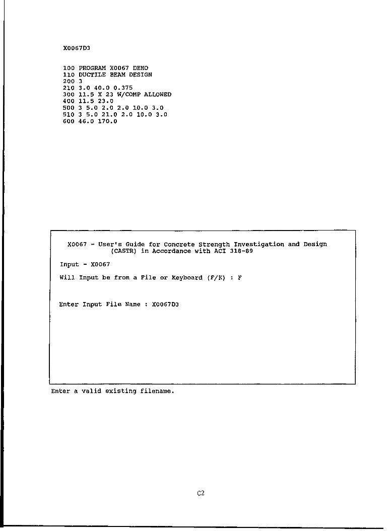
X0067D3
100 PROGRAM X0067 DEMO110 DUCTILE BEAM DESIGN200 3210 3.0 40.0 0.375300 11.5 X 23 W/COMP ALLOWED400 11.5 23.0500 3 5.0 2.0 2.0 10.0 3.0510 3 5.0 21.0 2.0 10.0 3.0600 46.0 170.0
X0067 - User's Guide for Concrete Strength Investigation and Design
(CASTR) in Accordance with ACI 318-89
Input - X0067
Will Input be from a File or Keyboard (F/K) : F
Enter Input File Name : X0067D3
Enter a valid existing filename.
C2
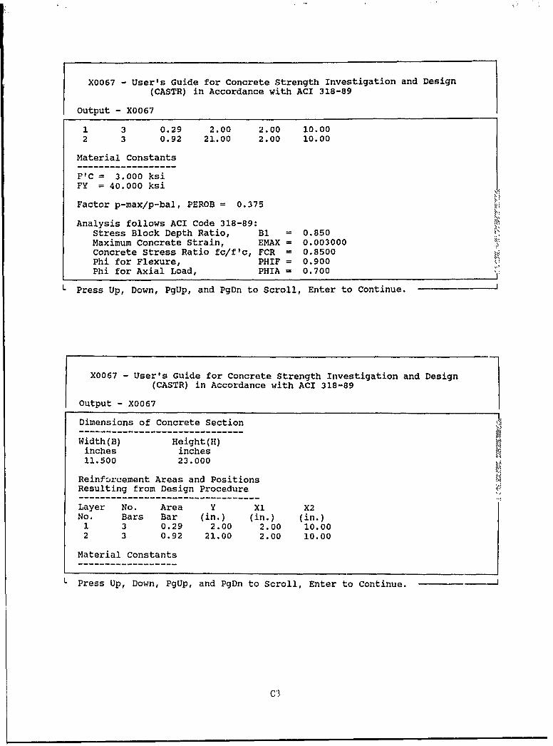
X0067 - User's Guide for Concrete Strength Investigation and Design
(CASTR) in Accordance with ACI 318-89
Output - X0067
1 3 0.29 2.00 2.00 10.002 3 0.92 21.00 2.00 10.00
Material Constants
F'C = 3.000 ksiFY = 40.000 ksi
Factor p-max/p-bal, PEROB = 0.375
Analysis follows ACI Code 318-89:Stress Block Depth Ratio, Bl = 0.850Maximum Concrete Strain, EMAX = 0.003000Concrete Stress Ratio fc/f'c, FCR = 0.8500Phi for Flexure, PHIF = 0.900Phi for Axial Load, PHIA = 0.700
L Press Up, Down, PgUp, and PgDn to Scroll, Enter to Continue.
X0067 - User's Guide for Concrete Strength Investigation and Design
(CASTR) in Accordance with ACI 318-89
Output - X0067
Dimensions of Concrete Section
Width(B) Height(H)inches inches11.500 23.000
Reinforcement Areas and PositionsResulting from Design Procedure
Layer No. Area Y Xl X2No. Bars Bar (in.) (in.) (in.)1 3 0.29 2.00 2.00 10.002 3 0.92 21.00 2.00 10.00
Material Constants
L Press Up, Down, PgUp, and PgDn to Scroll, Enter to Continue.
C3
0 -4
U)
0
0)~0 0 soC
W U o.400
U) -4 0U) 'x H
0 U
o 00
CM)
C4
LTi4
01 wH 00 0
~zW ~zO 0
00
NN
W44
1-4~
00W14/
W.4/
0/
U /)
i-l
00 0 0 0 00 0. 0 0 N%
C5
X0067 - User's Guide for Concrete Strength Investigation and Design
(CASTR) in Accordance with ACI 318-89
Output - X0067
ACI Code 318-89:
Required Strength
P(U) = 46.0 k PHI = 0.7841M(U) = 170.0 k-ft ASTOT/B*H = 0.0137
Results
Section falls within admissible range.Meets input data reinforcement limit requirement.
Minimum D for no comp steel = 23.84 inches
99.87 % of design strength used, intensile zone.
L Press Up, Down, PgUp, and PgDn to Scroll, Enter to Continue.
X0067 - User's Guide for Concrete Strength Investigation and Design
(CASTR) in Accordance with ACI 318-89
Output - X0067
End Of Data.
End or Rerun program (E/R) ?
ENTER RERUN OR END E
C6
Appendix D: Abbreviated Data File Guide
Abbreviated descriptionof data file Preparation
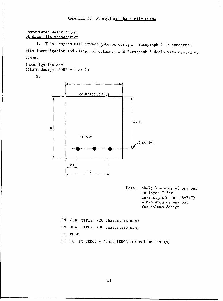
1. This program will investigate or design. Paragraph 2 is concerned
with investigation and design of columns, and Paragraph 3 deals with design of
beams.
Investigation andcolumn design (MODE - 1 or 2)
2.8
COMPRESSIVE FACE
AY 11)
H
ABAR (1)
SLAYER 1
I I
xx2
Note: ABAR(I) - area of one barin layer I forinvestigation or ABAR(I)- min area of one barfor column design
LN JOB TITLE (30 characters max)
LN JOB TITLE (30 characters max)
LN MODE
LN FC FY PEROB - (omit PEROB for column design)
DI
LN SECTION TITLE (30 characters max)
LN B H
Repeat LN NLAYfor eachload case LN NBAR(I), ABAR(I), AY(I), XXI(1), XX2(I)
LN (repeat above line NLAY times, NLAY = number of layers)
LN PU, RMU
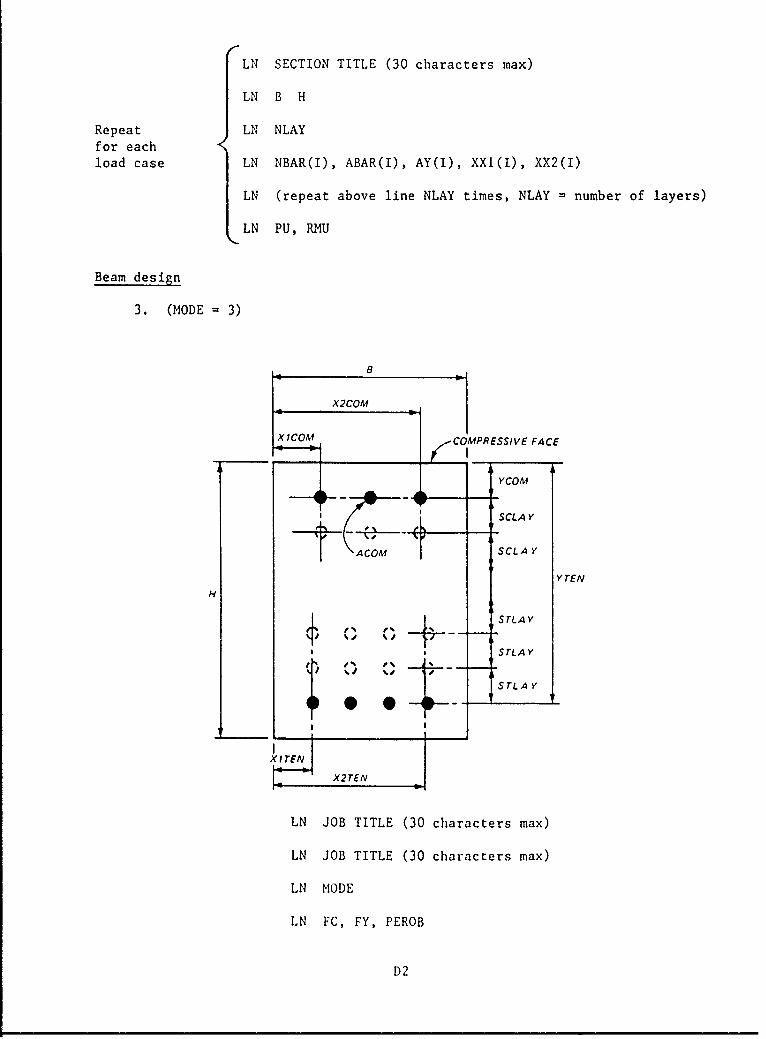
Beam design
3. (MODE = 3)
X2COM
XICOM C MPRESSIVE FACE
YCOM
SCLA Y
ACOM SCLA Y
YTENH!
STLAY
SrLA Y
X2TEN
LN JOB TITLE (30 characters max)
LN JOB TITLE (30 characters max)
LN MODE
LN FC, FY, PEROB
D2
LN SECTION TITLE (30 Characters max)
LN B, H
Repeat LN NCOM, ACOM, YCOM, XlCOM, X2COM, SCLAYfor eachload case
LN NTEN, ATEN, YTEN, XlTEN, X2TEN, STLAY
(N PU, RMU
Units
4. All dimensions are in inches, all areas are in square inches, and
concrete and steel yield strengths are in kips per square inch. Forces are in
kips at B/2 and H/2; compression is positive. Moments are in kip-feet and
include the moment caused by the fact that the axial force is not at H/2, and
moments must be positive tending to cause compression in the top face in the
diagram in paragraphs 2 and 3 of this appendix.
D3
Appendix E: Sample Investigation Problem
with Data Entered Interactively
Rerun Appendix A problem, except enter data interactively.
El
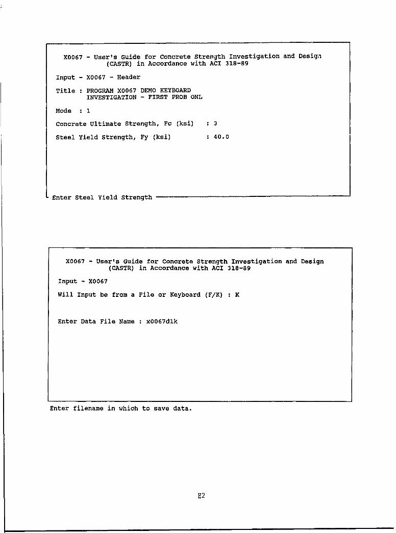
X0067 - User's Guide for Concrete Strength Investigation and Design
(CASTR) in Accordance with ACI 318-89
Input - X0067 - Header
Title PROGRAM X0067 DEMO KEYBOARDINVESTIGATION - FIRST PROB ONL
Mode 1
Concrete Ultimate Strength, Fc (ksi) : 3
Steel Yield Strength, Fy (ksi) : 40.0
Enter Steel Yield Strength
X0067 - User's Guide for Concrete Strength Investigation and Design(CASTR) in Accordance with ACI 318-89
Input - X0067
Will Input be from a File or Keyboard (F/K) : K
Enter Data File Name : x0067dlk
Enter filename in which to save data.
E2
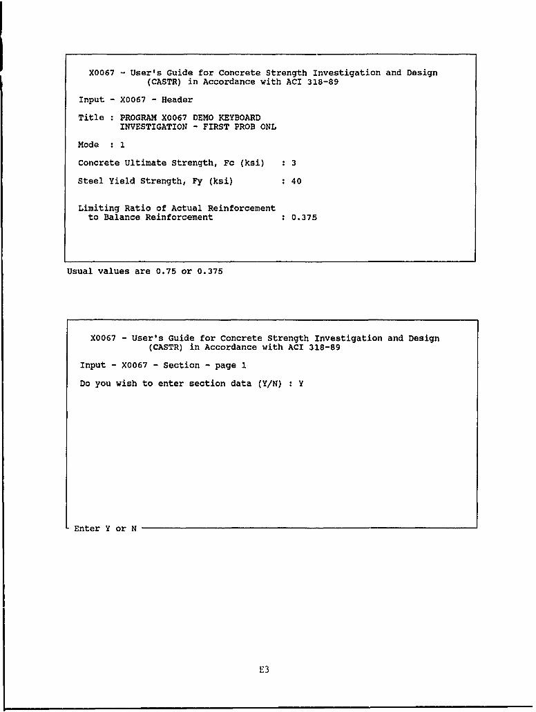
X0067 - User's Guide for Concrete Strength Investigation and Design
(CASTR) in Accordance with ACI 318-89
Input - X0067 - Header
Title PROGRAM X0067 DEMO KEYBOARDINVESTIGATION - FIRST PROB ONL
Mode 1
Concrete Ultimate Strength, Fc (ksi) : 3
Steel Yield Strength, Fy (ksi) : 40
Limiting Ratio of Actual Reinforcementto Balance Reinforcement : 0.375
Usual values are 0.75 or 0.375
X0067 - User's Guide for Concrete Strength Investigation and Design
(CASTR) in Accordance with ACI 318-89
Input - X0067 - Section - page 1
Do you wish to enter section data (Y/N) : Y
Enter Y or N
E3
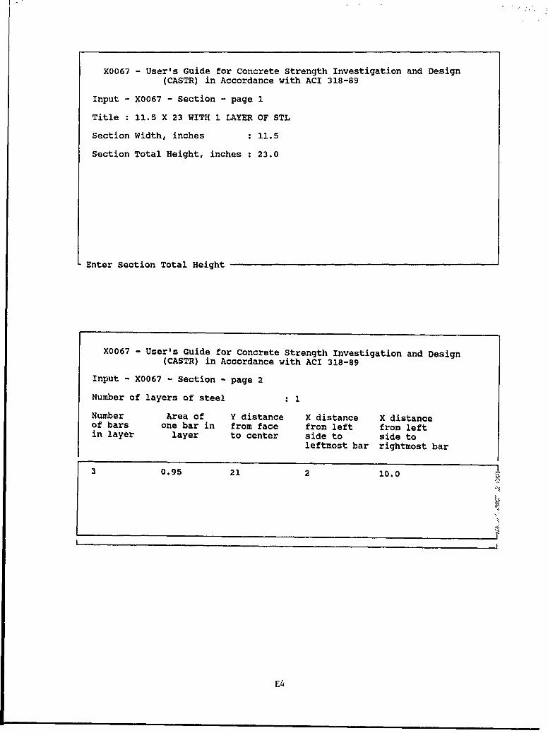
X0067 - User's Guide for Concrete Strength Investigation and Design
(CASTR) in Accordance with ACI 318-89
Input - X0067 - Section - page 1
Title 11.5 X 23 WITH 1 LAYER OF STL
Section Width, inches : 11.5
Section Total Height, inches : 23.0
Enter Section Total Height
X0067 - User's Guide for Concrete Strength Investigation and Design
(CASTR) in Accordance with ACI 318-89
Input - X0067 - Section - page 2
Number of layers of steel
Number Area of Y distance X distance X distanceof bars one bar in from face from left from leftin layer layer to center side to side to
leftmost bar rightmost bar
3 0.95 21 2 10.0 I
E4
X0067 - User's Guide for Concrete Strength Investigation and Design
(CASTR) in Accordance with ACI 318-89
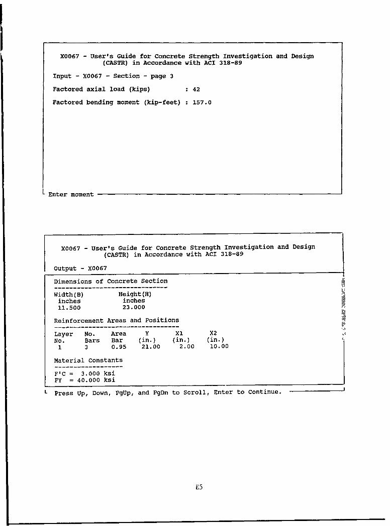
Input - X0067 - Section - page 3
Factored axial load (kips) : 42
Factored bending moment (kip-feet) : 157.0
L Enter moment
X0067 - User's Guide for Concrete Strength Investigation and Design
(CASTR) in Accordance with ACI 318-89
Output - X0067
Dimensions of Concrete Section
Width(B) Height(H)inches inches11.500 23.000
Reinforcement Areas and Positions
Layer No. Area Y Xl X2No. Bars Bar (in.) (in.) (in.)1 3 0.95 21.00 2.00 10.00
Material Constants
F'C = 3.000 ksiFY = 40.000 ksi
Press Up, Down, PgUp, and PgDn to Scroll, Enter to Continue.
E5
X0067 - User's Guide for Concrete Strength Investigation and Design
(CASTR) in Accordance with ACI 318-89
Output - X0067
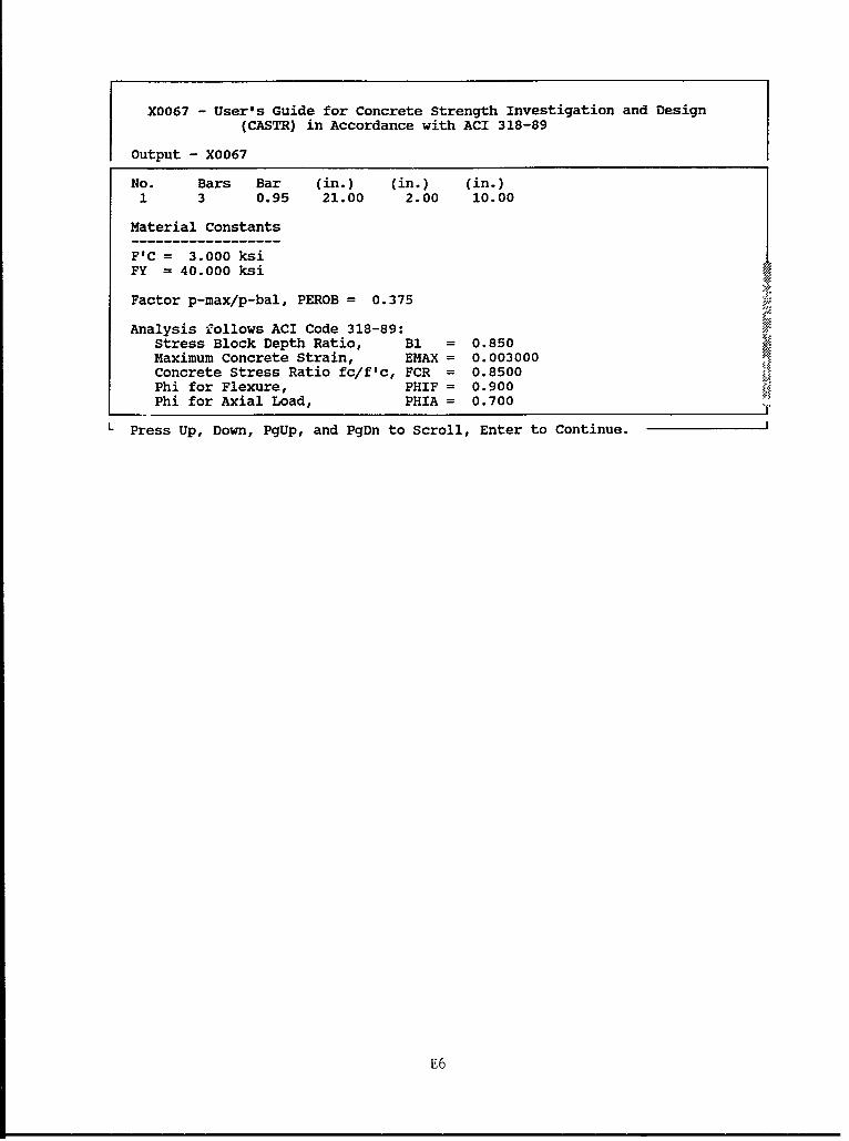
No. Bars Bar (in.) (in.) (in.)1 3 0.95 21.00 2.00 10.00
Material Constants
F'C = 3.000 ksiFY = 40.000 ksi
Factor p-max/p-bal, PEROB = 0.375
Analysis follows ACI Code 318-89:Stress Block Depth Ratio, B1 = 0.850Maximum Concrete Strain, EMAX = 0.003000Concrete Stress Ratio fc/f'c, FCR = 0.8500Phi for Flexure, PHIF = 0.900Phi for Axial Load, PHIA = 0.700
L Press Up, Down, PgUp, and PgDn to Scroll, Enter to Continue.
E6
Z OE-
4O014
>4 D
(0F4 w 1 ~O014 0 OH
0 F4
o 'o 1 NH z X
(1) ri H (03W 0 W )
0
E7
eg( U z (9 OFz z Z- z z H W
0: (1 Ix 0H Q 0 :
* E- w 40 w 0
* f 0 OHI- 04 Z
00 H -
N NI
H 0Q
0 oF-4
N0m UH
OD / H N N041
00 L
H /-00
4 (44
00Z0
0 0
0 0 0 0 00 00 0 0 0 0 0 0 0- 0
LO v) () Nq 7-1 0 1 1
E8
X0067 - User's Guide for Concrete Strength Investigation and Design
(CASTR) in Accordance with ACI 318-89
Output - X0067
ACI Code 318-89:
Required Strength
P(U) = 42.0 k PHI = 0.7941M(U) = 157.0 k-ft ASTOT/B*H = 0.0108
Results
Section falls within admissible range.Does not meet input data reinforcement limit requirement.
Minimum D for no comp steel = 22.62 inches
94.24 % of design strength used, in %tensile zone.
L Press Up, Down, PgUp, and PgDn to Scroll, Enter to Continue.
E9
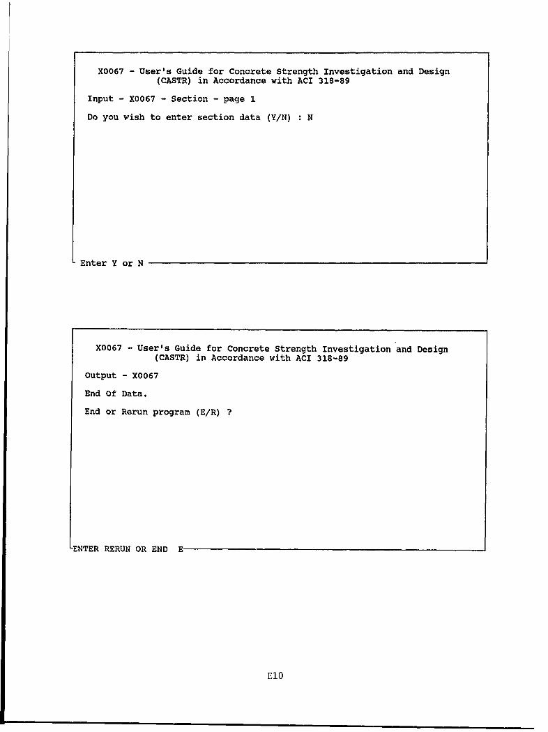
X0067 - User's Guide for Concrete Strength Investigation and Design
(CASTR) in Accordance with ACI 318-89
Input - X0067 - Section - page 1
Do you wish to enter section data (Y/N) : N
Enter Y or N
X0067 - User's Guide for Concrete Strength Investigation and Design
(CASTR) in Accordance with ACI 318-89
Output - X0067
End Of Data.
End or Rerun program (E/R) ?
-ENTER RERUN OR END E
El0
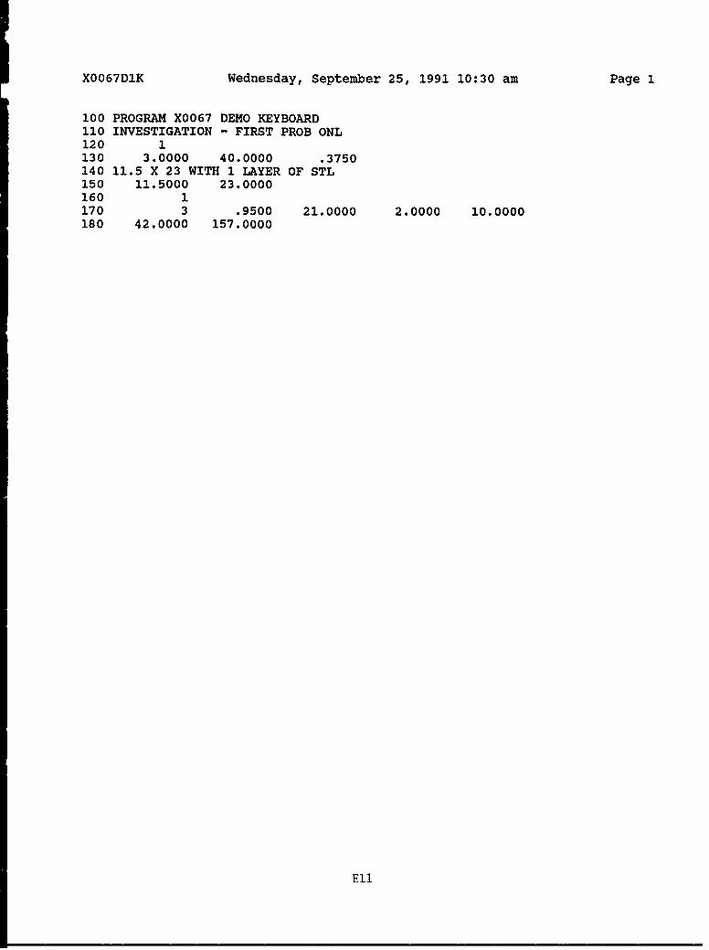
X0067D1K Wednesday, September 25, 1991 10:30 am Page 1
100 PROGRAM X0067 DEMO KEYBOARD110 INVESTIGATION - FIRST PROB ONL120 1130 3.0000 40.0000 .3750140 11.5 X 23 WITH 1 LAYER OF STL150 11.5000 23.0000160 1170 3 .9500 21.0000 2.0000 10.0000180 42.0000 157.0000
Ell
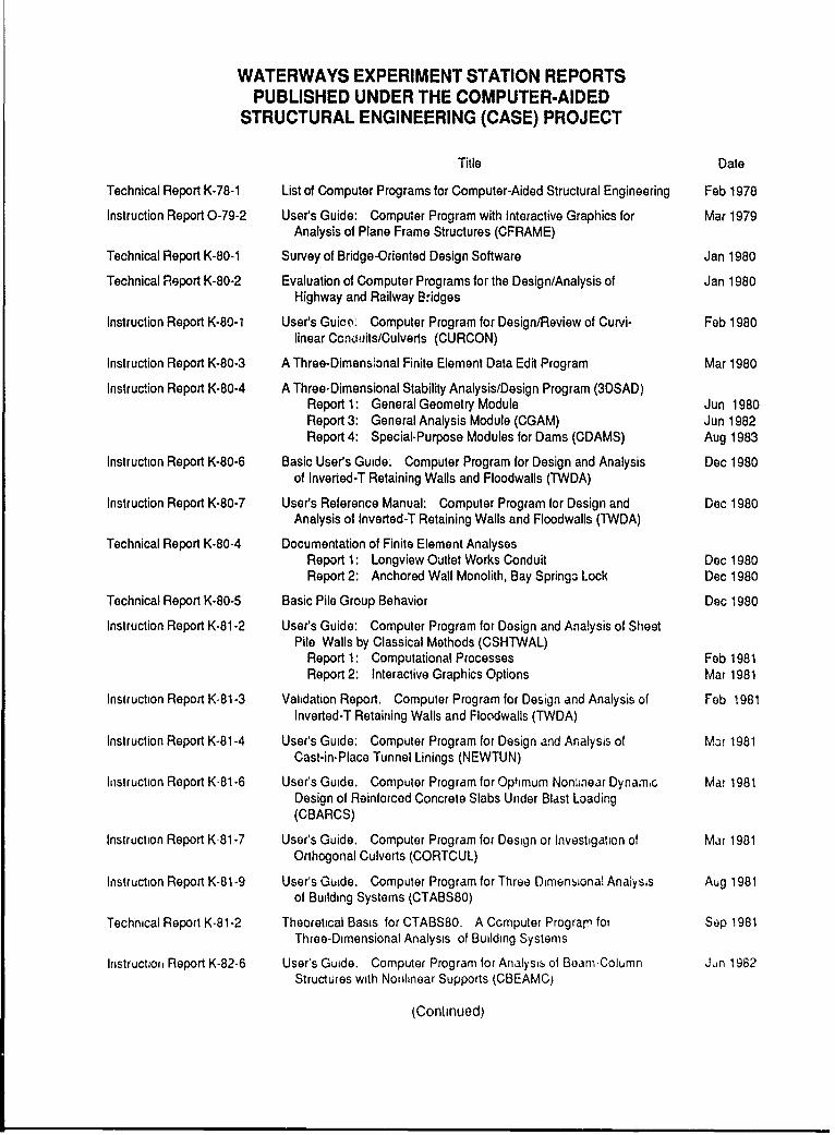
WATERWAYS EXPERIMENT STATION REPORTSPUBLISHED UNDER THE COMPUTER-AIDED
STRUCTURAL ENGINEERING (CASE) PROJECT
Title Date
Technical Report K-78-1 List of Computer Programs for Computer-Aided Structural Engineering Feb 1978
Instruction Report 0-79-2 User's Guide: Computer Program with Interactive Graphics for Mar 1979Analysis of Plane Frame Structures (CFRAME)
Technical Report K-80-1 Survey of Bridge-Oriented Design Software Jan 1980
Technical Report K-80-2 Evaluation of Computer Programs for the Design/Analysis of Jan 1980Highway and Railway Bridges
Instruction Report K-80-1 User's Guico: Computer Program for Design/Review of Curvi- Feb 1980linear Conkiuits/Culverts (CURCON)
Instruction Report K-80-3 A Three-Dimensional Finite Element Data Edit Program Mar 1980
Instruction Report K-80-4 A Three-Dimensional Stability Analysis/Design Program (3DSAD)Report 1: General Geometry Module Jun 1980Report 3: General Analysis Module (CGAM) Jun 1982Report 4: Special-Purpose Modules for Dams (CDAMS) Aug 1983
Instruction Report K-80-6 Basic User's Guide: Computer Program for Design and Analysis Dec 1980of Inverted-T Retaining Walls and Floodwalls (TWDA)
Instruction Report K-80-7 User's Reference Manual: Computer Program for Design and Dec 1980Analysis of Inverted-T Retaining Walls and Floodwalls (TWDA)
Technical Report K-80-4 Documentation of Finite Element AnalysesReport 1: Longview Outlet Works Conduit Dec 1980Report 2: Anchored Wall Monolith, Bay Springs Lock Dec 1980
Technical Report K-80-5 Basic Pile Group Behavior Dec 1980
Instruction Report K-81-2 User's Guide: Computer Program for Design and Analysis of SheetPile Walls by Classical Methods (CSHIWAL)
Report 1: Computational Processes Feb 1981Report 2: Interactive Graphics Options Mar 1981
Instruction Report K-81-3 Validation Report. Computer Program for Design and Analysis of Feb 1981Inverted-T Retaining Walls and Floodwalls (TWDA)
Instruction Report K-81-4 User's Guide: Computer Program for Design and Analysis of Mar 1981Cast-in-Place Tunnel Linings (NEWTUN)
Instruction Report K-81-6 User's Guide. Computer Program for Optimum Nonfinear Dynamc Mar 1981Design of Reinforced Concrete Slabs Under Blast Loading(CBARCS)
Instruction Report K-81-7 User's Guide. Computer Program for Design or Investigation of Mar 1981Orthogonal Culverts (CORTCUL)
Instruction Report K-81-9 User's Guide. Computer Program for Three Dimenional Analysis Aug 1981of Building Systems (CTABS80)
Technical Report K-81-2 Theoretical Basis for CTABS80. A Ccmputer Prograr for Sep 1981Three-Dimensional Analysis of Building Systems
Instruction Report K-82-6 User's Guide. Computer Program for Analysib of Beam-Column Jun 1982Structures with Nonlinear Supports (CBEAMC)
(Continued)
WATERWAYS EXPERIMENT STATION REPORTSPUBLISHED UNDER THE COMPUTER-AIDED
STRUCTURAL ENGINEERING (CASE) PROJECT
(Continued)Title Date
Instruction Report K-82-7 User's Guide: Computer Program for Bearing Capacity Analysis Jun 1982of Shallow Foundations (CBEAR)
Instruction Report K-83-1 User's Guide: Computer Program with Interactive Graphics for Jan 1983Analysis of Plane Frame Structures (CFRAME)
Instruction Report K-83-2 User's Guide: Computer Program for Generation of Engineering Jun 1983Geometry (SKETCH)
Instruction Report K-83-5 User's Guide: Computer Program to Calculate Shear, Moment, Jul 1983and Thrust (CSMT) from Stress Results of a Two-DimensionalFinite Element Analysis
Technical Report K-83-1 Basic Pile Group Behavior Sep 1983
Technical Report K-83-3 Reference Manual: Computer Graphics Program for Generation of Sep 1983Engineering Geometry (SKETCH)
Technical Report K-83-4 Case Study of Six Major General-Purpose Finite Element Programs Oct 1983
Instruction Report K-84-2 User's Guide: Computer Program for Optimum Dynamic Design Jan 1984of Nonlinear Metal Plates Under Blast Loading (CSDOOR)
Instruction Report K-84-7 User's Guide: Computer Program for Determining Induced Aug 1984Stresses and Consolidation Settlements (CSETT)
Instruction Report K-84-8 Seepage Analysis of Confined Flow Problems by the Method of Sep 1984Fragments (CFRAG)
Instruction Report K-84-11 User's Guide for Computer Program CGFAG, Concrete General Sep 1984Flexure Analysis with Graphics
Technical Report K-84-3 Computer-Aided Drafting and Design for Corps Structural Oct 1984Engineers
Technical Report ATC-86-5 Decision Logic Table Formulation of ACI 318-77, Building Code Jun 1986Requirements for Reinforced Concrete for Automated Con-straint Processing, Volumes I and II
Technical Report ITL-87-2 A Case Committee Study of Finite Element Analysis of Concrete Jan 1987Flat Slabs
Instruction Report ITL-87-1 User's Guide: Computer Program for Two-Dimensional Analysis Apr 1987of U-Frame Structures (CUFRAM)
Instruction Report ITL-87-2 User's Guide: For Concrete Strength Investigation and Design May 1987(CASTR) in Accordance with ACI 318-83
Technical Report ITL-87-6 Finite-Element Method Package for Solving Steady-State Seepage May 1987Problems
Instruction Report ITL-87-3 User's Guide: A Three Dimensional Stability Analysis/Design Jun 1987Program (3DSAD) Module
Report 1: Revision 1: General Geometry Jun 1987Report 2: General Loads Module Sep 1989Report 6: Free-Body Module Sep 1989
(Continued)
WATERWAYS EXPERIMENT STATION REPORTSPUBLISHED UNDER THE COMPUTER-AIDED
STRUCTURAL ENGINEERING (CASE) PROJECT
(Continued)
Title Date
Instruction Report ITL-87-4 User's Guide: 2-D Frame Analysis Link Program (LINK2D) Jun 1987
Technical Report ITL-87-4 Finite Element Studies of a Horizontally Framed Miter Gate Au, 1987Report 1: Initial and Refined Finite Element Models (Phases
A, B, and C), Volumes I and IIReport 2: Simplified Frame Model (Phase D)Report 3: Alternate Configuration Miter Gate Finite Element
Studies-Open SectionReport 4: Alternate Configuration Miter Gate Finite Element
Studies-Closed SectionsReport 5: Alternate Configuration Miter Gate Finite Element
Studies-Additional Closed SectionsReport 6: Elastic Buckling of Girders in Horizontally Framed
Miter GatesReport 7: Application and Summary
Instruction Report GL-87-1 User's Guide: UTEXAS2 Slope-Stability Package, Volume I, Aug 1987User's Manual
Instruction Report ITL-87-5 Sliding Stability of Concrete Structures (CSLIDE) Oct 1987
Instruction Report ITL-87-6 Criteria Specifications for and Validation of a Computer Program Dec 1987for the Design or Investigation of Horizontally Framed MiterGates (CMITER)
Technical Report ITL-87-8 Proceduie for Static Analysis of Gravity Dams Using the Finite Jan 1988Element Method - Phase 1 a
Instruction Report ITL-88-1 User's Guide: Computer Program for Analysis of Planar Grid Feb 1988Structures (CGRID)
Technical Report ITL-88-1 Development of Design Formulas for Ribbed Mat Foundations Apr 1988on Expansive Soils
Technical Report ITL-88-2 User's Guide: Pile Group Graphics Display (CPGG) Post- Apr 1988processor to CPGA Program
Instruction Report ITL-88-2 User's Guide for Design and Investigation of Horizontally Framed Jun 1988Miter Gates (CMITER)
Instruction Report ITL-88-4 User's Guide for Revised Computer Program to Calculate Shear, Sep 1988Moment, and Thrust (CSMT)
Instruction Report GL-87-1 User's Guide. UTEXAS2 Slope-Stability Package, Vo' me II, Feb 1989Theory
Technical Report ITL-89-3 User's Guide. Pile Group Analysis (CPGA) Computer Group Jul 1989
Technical Report ITL-89-4 CBASIN-Structural Design of Saint Anthony Falls Stilling Basins Aug 1989According to Corps of Engineers Criteria for HydraulicStructures; Computer Program X0098
(Continued)
WATERWAYS EXPERIMENT STATION REPORTSPUBLISHED UNDER THE COMPUTER-AIDED
STRUCTURAL ENGINEERING (CASE) PROJECT
(Concluded)
Title Date
Technical Report ITL-89-5 CCHAN-Structural Design of Rectangular Channels According Aug 1989to Corps of Engineers Criteria for HydraulicStructures; Computer Program X0097
Technical Report ITL-6- 6 The Response-Spectrum Dynamic Analysis of Gravity Dams Using Aug 1989the Finite Element Method; Phase II
Contract Report ITL-89-1 State of the Art on Expert Systems Applications in Design, Sep 1989Construction, and Maintenance of Structures
Instruction Report ITL-90-1 User's Guide: Computer Program for Design and Analysis Feb 1990of Sheet Pile Walls by Classical Methods (CWALSHT)
Technical Report ITL-90-3 Investigation and Design of U-Frame Structures Using May 1990Program CUFRBC
Volumo A: Program Criteria and DocumentationVolume B: User's Guide for BasinsVolume C: User's Guide for Channels
Instruction Report ITL-90-6 User's Guide: Computer Program for Two-Dimensional Analysis Sep 1990of U-Frame or W-Frame Structures (CWFRAM)
Instruction Report ITL-90-2 User's Guide: Pile Group-Concrete Pile Analysis Program Jun 1990(CPGC) Preprocessor to CPGA Program
Technical Report ITL-91-3 Application of Finite Element, Grid Generation, and Scientific Sep 1990Visualization Techniques to 2-D and 3-D Seepage andGroundwater Modeling
Instruction Report ITL-91-1 User's Guide: Computer Program for Design and Analysis Oct 1991of Sheet-Pile Walls by Classical Methods (CWALSHT)Including Rowe's Moment Reduction
Instruction Report ITL-87-2 User's Guide for Concrete Strength Investigation and Design Mar 1992(Revised) (CASTR) in Accordance with ACI 318-89