Embed Size (px)
DESCRIPTION
complete manual for the AW4 AT
Citation preview
AW–4 AUTOMATIC TRANSMISSIONINDEX
page page
GENERAL INFORMATION
AW–4 AUTOMATIC TRANSMISSION . . . . . . . . . 164
CAUSES OF BURNT FLUID . . . . . . . . . . . . . . . 165
EFFECTS OF INCORRECT FLUID LEVEL . . . . 164
FLUID CONTAMINATION . . . . . . . . . . . . . . . . . 165
RECOMMENDED FLUID CAPACITY . . . . . . . . . 164
TRANSMISSION IDENTIFICATION . . . . . . . . . . 164
TRANSMISSION RANGES AND SHIFT LEVER
POSITIONS . . . . . . . . . . . . . . . . . . . . . . . . . . 165
DESCRIPTION AND OPERATION
BRAKE TRANSMISSION SHIFT INTERLOCK
MECHANISM . . . . . . . . . . . . . . . . . . . . . . . . . 176
ELECTRONIC CONTROLS . . . . . . . . . . . . . . . . 166
FIRST/SECOND/THIRD/REVERSE GEAR
COMPONENTS . . . . . . . . . . . . . . . . . . . . . . . 167
FOURTH GEAR OVERDRIVE
COMPONENTS . . . . . . . . . . . . . . . . . . . . . . . 166
GEARTRAIN OPERATION AND APPLICATION
CHARTS . . . . . . . . . . . . . . . . . . . . . . . . . . . . 168
HYDRAULIC SYSTEM . . . . . . . . . . . . . . . . . . . 169
OIL PUMP . . . . . . . . . . . . . . . . . . . . . . . . . . . . 169
SENSORS . . . . . . . . . . . . . . . . . . . . . . . . . . . . 166
TORQUE CONVERTER . . . . . . . . . . . . . . . . . . 166
TRANSMISSION CONTROL MODULE (TCM) . . 166
TRANSMISSION COOLER . . . . . . . . . . . . . . . . 176
TRANSMISSION VALVE BODY
COMPONENTS . . . . . . . . . . . . . . . . . . . . . . . 169
TRANSMISSION VALVE BODY SOLENOIDS . . 166
DIAGNOSIS AND TESTING
FLOW TESTING TRANSMISSION MAIN
COOLER . . . . . . . . . . . . . . . . . . . . . . . . . . . . 184
GEARSHIFT CABLE . . . . . . . . . . . . . . . . . . . . . 183
GENERAL DIAGNOSIS INFORMATION . . . . . . . 177
HYDRAULIC PRESSURE TEST . . . . . . . . . . . . 179
MANUAL SHIFTING TEST . . . . . . . . . . . . . . . . 178
PARK/NEUTRAL POSITION SWITCH . . . . . . . . 183
PRELIMINARY INSPECTION AND
ADJUSTMENT . . . . . . . . . . . . . . . . . . . . . . . . 177
PRESSURE TEST ANALYSIS . . . . . . . . . . . . . . 179
SERVICE DIAGNOSIS . . . . . . . . . . . . . . . . . . . 180
SPEED SENSOR TESTING . . . . . . . . . . . . . . . 183
STALL SPEED TEST ANALYSIS . . . . . . . . . . . . 180
TEST PROCEDURE . . . . . . . . . . . . . . . . . . . . . 180
THROTTLE VALVE CABLE . . . . . . . . . . . . . . . . 183
TIME LAG TEST . . . . . . . . . . . . . . . . . . . . . . . . 180
TIME LAG TEST ANALYSIS . . . . . . . . . . . . . . . 180
TORQUE CONVERTER STALL TEST . . . . . . . . 179
TORQUE CONVERTER STATOR CLUTCH
INSPECTION . . . . . . . . . . . . . . . . . . . . . . . . . 184
TRANSMISSION SOLENOID TESTING . . . . . . 180
SERVICE PROCEDURES
ALUMINUM THREAD REPAIR . . . . . . . . . . . . . 186
CHECKING FLUID CONDITION . . . . . . . . . . . . 185
CHECKING FLUID LEVEL . . . . . . . . . . . . . . . . 185
FLUSHING COOLERS AND TUBES . . . . . . . . . 186
OIL PUMP VOLUME CHECK . . . . . . . . . . . . . . 185
REFILLING AFTER OVERHAUL OR FLUID/
FILTER CHANGE . . . . . . . . . . . . . . . . . . . . . . 185
TRANSMISSION CONTROL MODULE (TCM)
SERVICE . . . . . . . . . . . . . . . . . . . . . . . . . . . . 185
REMOVAL AND INSTALLATION
ACCUMULATOR PISTONS AND SPRINGS . . . . 199
ADAPTER HOUSING SEAL . . . . . . . . . . . . . . . 189
BRAKE TRANSMISSION SHIFT INTERLOCK . . 193
GEARSHIFT CABLE . . . . . . . . . . . . . . . . . . . . . 192
MANUAL VALVE SHAFT SEAL . . . . . . . . . . . . . 198
OIL PUMP SEAL . . . . . . . . . . . . . . . . . . . . . . . . 203
PARK ROD AND PAWL . . . . . . . . . . . . . . . . . . . 201
PARK/NEUTRAL POSITION SWITCH . . . . . . . . 191
SECOND COAST BRAKE SERVO . . . . . . . . . . 200
SOLENOID HARNESS ADAPTER SEAL . . . . . . 196
SPEED SENSOR . . . . . . . . . . . . . . . . . . . . . . . 189
SPEED SENSOR ROTOR-SPEEDOMETER
DRIVE GEAR . . . . . . . . . . . . . . . . . . . . . . . . . 190
SPEEDOMETER ADAPTER . . . . . . . . . . . . . . . 189
TORQUE CONVERTER . . . . . . . . . . . . . . . . . . 188
TRANSMISSION AND TORQUE
CONVERTER . . . . . . . . . . . . . . . . . . . . . . . . 187
TRANSMISSION CONTROL MODULE . . . . . . . 196
TRANSMISSION THROTTLE CABLE . . . . . . . . 202
TRANSMISSION VALVE BODY . . . . . . . . . . . . . 194
TRANSMISSION VALVE BODY SOLENOIDS . . 193
DISASSEMBLY AND ASSEMBLY
DIRECT CLUTCH . . . . . . . . . . . . . . . . . . . . . . . 243
FORWARD CLUTCH . . . . . . . . . . . . . . . . . . . . . 247
FRONT PLANETARY GEAR . . . . . . . . . . . . . . . 252
OIL PUMP . . . . . . . . . . . . . . . . . . . . . . . . . . . . 232
OVERDRIVE PLANETARY GEAR AND
CLUTCH . . . . . . . . . . . . . . . . . . . . . . . . . . . . 234
OVERDRIVE SUPPORT . . . . . . . . . . . . . . . . . . 240
PLANETARY/BRAKE PACK/OUTPUT SHAFT . . 260
SECOND BRAKE . . . . . . . . . . . . . . . . . . . . . . . 256
SUN GEAR AND NO. 1 ONE–WAY CLUTCH . . . 254
TRANSMISSION . . . . . . . . . . . . . . . . . . . . . . . . 204
TRANSMISSION VALVE BODY . . . . . . . . . . . . . 264
CLEANING AND INSPECTION
TRANSMISSION PARTS CLEANING AND
INSPECTION . . . . . . . . . . . . . . . . . . . . . . . . . 267
XJ TRANSMISSION AND TRANSFER CASE 21 - 163
ADJUSTMENTS
BRAKE TRANSMISSION SHIFT INTERLOCK
CABLE ADJUSTMENT . . . . . . . . . . . . . . . . . . 267
GEARSHIFT CABLE . . . . . . . . . . . . . . . . . . . . . 267
TRANSMISSION THROTTLE VALVE CABLE
ADJUSTMENT . . . . . . . . . . . . . . . . . . . . . . . . 268
SPECIFICATIONS
AW-4 AUTOMATIC TRANSMISSION . . . . . . . . . 269
SPECIAL TOOLS
AW-4 . . . . . . . . . . . . . . . . . . . . . . . . . . . . . . . . 278
GENERAL INFORMATIONAW–4 AUTOMATIC TRANSMISSIONThe AW–4 is a 4–speed, electronically controlled
automatic transmission (Fig. 1).The running gear consists of an oil pump, plane-
tary gear sets, clutch and brake units, hydraulicaccumulators, a valve body with electrical solenoids,and a transmission control module (TCM). Cables areused to provide shift and throttle pressure controlinformation. A park/neutral position switch permitsengine starting in the Park and Neutral ranges only.The valve body solenoids are controlled by signals
from the transmission control module (TCM). Signalsequence is determined by inputs from various sen-sors to the TCM.Fourth gear is an 0.75:1 ratio overdrive range.
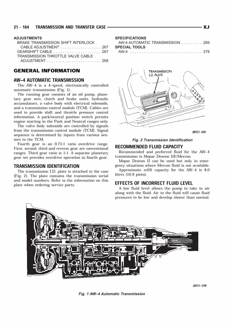
First, second, third and reverse gear are conventionalranges. Third gear ratio is 1:1. A separate planetarygear set provides overdrive operation in fourth gear.TRANSMISSION IDENTIFICATIONThe transmission I.D. plate is attached to the case
(Fig. 2). The plate contains the transmission serialand model numbers. Refer to the information on thisplate when ordering service parts.
RECOMMENDED FLUID CAPACITYRecommended and preferred fluid for the AW–4
transmission is Mopar Dexron IIE/Mercon.Mopar Dexron II can be used but only in emer-
gency situations where Mercon fluid is not available.Approximate refill capacity for the AW–4 is 8.0
liters (16.9 pints).EFFECTS OF INCORRECT FLUID LEVELA low fluid level allows the pump to take in air
along with the fluid. Air in the fluid will cause fluidpressures to be low and develop slower than normal.
Fig. 1 AW–4 Automatic Transmission
Fig. 2 Transmission Identification
21 - 164 TRANSMISSION AND TRANSFER CASE XJ
If the transmission is overfilled, the gears churn thefluid into foam. This aerates the fluid and causingthe same conditions occurring with a low level. Ineither case, air bubbles cause fluid overheating, oxi-dation and varnish buildup which interferes withvalve, clutch and servo operation. Foaming alsocauses fluid expansion which can result in fluid over-flow from the transmission vent or fill tube. Fluidoverflow can easily be mistaken for a leak if inspec-tion is not careful.CAUSES OF BURNT FLUIDBurnt, discolored fluid is a result of overheating
which has two primary causes.(1) A result of restricted fluid flow through the
main and/or auxiliary cooler. This condition is usu-ally the result of a faulty or improperly installeddrainback valve, a damaged main cooler, or severerestrictions in the coolers and lines caused by debrisor kinked lines.(2) Heavy duty operation with a vehicle not prop-
erly equipped for this type of operation. Trailer tow-ing or similar high load operation will overheat thetransmission fluid if the vehicle is improperlyequipped. Such vehicles should have an auxiliarytransmission fluid cooler, a heavy duty cooling sys-tem, and the engine/axle ratio combination needed tohandle heavy loads.FLUID CONTAMINATIONTransmission fluid contamination is generally a
result of: adding incorrect fluid failure to clean dipstick and fill tube when
checking level engine coolant entering the fluid internal failure that generates debris overheat that generates sludge (fluid break-
down) failure to reverse flush cooler and lines after
repair failure to replace contaminated converter after
repairThe use of non recommended fluids can result in
transmission failure. The usual results are erraticshifts, slippage, abnormal wear and eventual failuredue to fluid breakdown and sludge formation. Avoidthis condition by using recommended fluids only.The dipstick cap and fill tube should be wiped
clean before checking fluid level. Dirt, grease andother foreign material on the cap and tube could fallinto the tube if not removed beforehand. Take thetime to wipe the cap and tube clean before withdraw-ing the dipstick.Engine coolant in the transmission fluid is gener-
ally caused by a cooler malfunction. The only remedy
is to replace the radiator as the cooler in the radiatoris not a serviceable part. If coolant has circulatedthrough the transmission for some time, an overhaulmay also be necessary; especially if shift problemshad developed.The transmission cooler and lines should be
reverse flushed whenever a malfunction generatessludge and/or debris. The torque converter shouldalso be replaced at the same time.Failure to flush the cooler and lines will result in
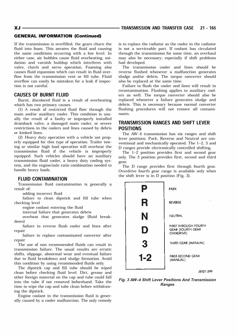
recontamination. Flushing applies to auxiliary cool-ers as well. The torque converter should also bereplaced whenever a failure generates sludge anddebris. This is necessary because normal converterflushing procedures will not remove all contami-nants.TRANSMISSION RANGES AND SHIFT LEVERPOSITIONSThe AW–4 transmission has six ranges and shift
lever positions. Park, Reverse and Neutral are con-ventional and mechanically operated. The 1–2, 3 andD ranges provide electronically controlled shifting.The 1–2 position provides first and second gear
only. The 3 position provides first, second and thirdgear.The D range provides first through fourth gear.
Overdrive fourth gear range is available only whenthe shift lever is in D position (Fig. 3).
Fig. 3 AW–4 Shift Lever Positions And Transmission
Ranges
XJ TRANSMISSION AND TRANSFER CASE 21 - 165GENERAL INFORMATION (Continued)

DESCRIPTION AND OPERATIONELECTRONIC CONTROLSThe AW–4 is electronically controlled in 1, 2, 3 and
D ranges. Controls consist of the transmission controlmodule (TCM), valve body solenoids and various sen-sors. The sensors monitor vehicle speed, throttleopening, shift lever position and brake pedal applica-tion.TRANSMISSION CONTROL MODULE (TCM)The module determines shift and converter clutch
engagement timing based on signals from sensors.The valve body solenoids are activated, or deacti-vated accordingly.The TCM has a self diagnostic program. Compo-
nent and circuitry malfunctions can be diagnosedwith the DRB scan tool. Once a malfunction is notedand stored in control module memory, it is retainedeven after the problem has been corrected. To cancela stored malfunction, disconnect and reconnect the Trans. fuse in the module harness.TRANSMISSION VALVE BODY SOLENOIDSThe solenoids are mounted on the valve body and
operated by the TCM. The solenoids control operationof the converter clutch and shift valves in response toinput signals from the module.SENSORSSensors include: throttle position sensor (TPS) transmission speed sensor vehicle speed sensor park/neutral position switch brake switchThe throttle position sensor is mounted on the
throttle body. It electronically determines throttleposition and relays this information to the transmis-sion control module to determine shift points andconverter clutch engagement.The transmission speed sensor consists of a rotor
and magnet on the transmission output shaft and aswitch in the extension housing or adapter. The sen-sor switch is activated each time the rotor and mag-net complete one revolution. Sensor signals are sentto the transmission control module.The park/neutral position switch is mounted on the
valve body manual shaft. The switch signals shiftlinkage and manual valve position to the transmis-sion control module through an interconnecting har-ness. The switch prevents engine starting in all gearsother than Park or Neutral.The brake switch is in circuit with the torque con-
verter clutch solenoid. The switch disengages theconverter clutch whenever the brakes are applied.
The switch is mounted on the brake pedal bracketand signals the transmission control module whenthe pedal is pressed or released.TORQUE CONVERTERA three element torque converter is used for all
applications. The converter contains an impeller, sta-tor, and turbine.The AW–4 converters are all equipped with a con-
verter clutch mechanism. The clutch consists of asliding clutch piston, clutch springs and the clutchdisc material (Fig. 4). The clutch provides optimumtorque transfer and economy when engaged.
The clutch disc is attached to the converter frontcover. The clutch piston and clutch springs areattached to the turbine hub. The springs dampenengine firing impulses and loads during the initialphase of converter clutch engagement.Clutch engagement is controlled by transmission
valve body solenoid number three and by the con-verter clutch relay valve. The solenoid channels linepressure to the clutch through the relay valve atclutch engagement speeds.Torque converter clutch engagement occurs in sec-
ond gear in 1–2 position; third gear in 3 position andthird and fourth gear in D position.FOURTH GEAR OVERDRIVE COMPONENTSThe overdrive system consists of the input shaft,
one–way clutch, planetary sun gear, ring gear, plan-etary carrier, overdrive clutch and overdrive brake(Fig. 5). The overdrive elements are controlled and
Fig. 4 Torque Converter (With Clutch)
21 - 166 TRANSMISSION AND TRANSFER CASE XJ
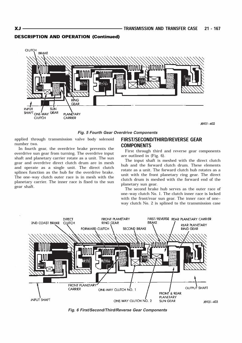
applied through transmission valve body solenoidnumber two.In fourth gear, the overdrive brake prevents the
overdrive sun gear from turning. The overdrive inputshaft and planetary carrier rotate as a unit. The sungear and overdrive direct clutch drum are in meshand operate as a single unit. The direct clutchsplines function as the hub for the overdrive brake.The one–way clutch outer race is in mesh with theplanetary carrier. The inner race is fixed to the sungear shaft.
FIRST/SECOND/THIRD/REVERSE GEARCOMPONENTSFirst through third and reverse gear components
are outlined in (Fig. 6).The input shaft is meshed with the direct clutch
hub and the forward clutch drum. These elementsrotate as a unit. The forward clutch hub rotates as aunit with the front planetary ring gear. The directclutch drum is meshed with the forward end of theplanetary sun gear.The second brake hub serves as the outer race of
one–way clutch No. 1. The clutch inner race is lockedwith the front/rear sun gear. The inner race of one–way clutch No. 2 is splined to the transmission case
Fig. 5 Fourth Gear Overdrive Components
Fig. 6 First/Second/Third/Reverse Gear Components
XJ TRANSMISSION AND TRANSFER CASE 21 - 167DESCRIPTION AND OPERATION (Continued)
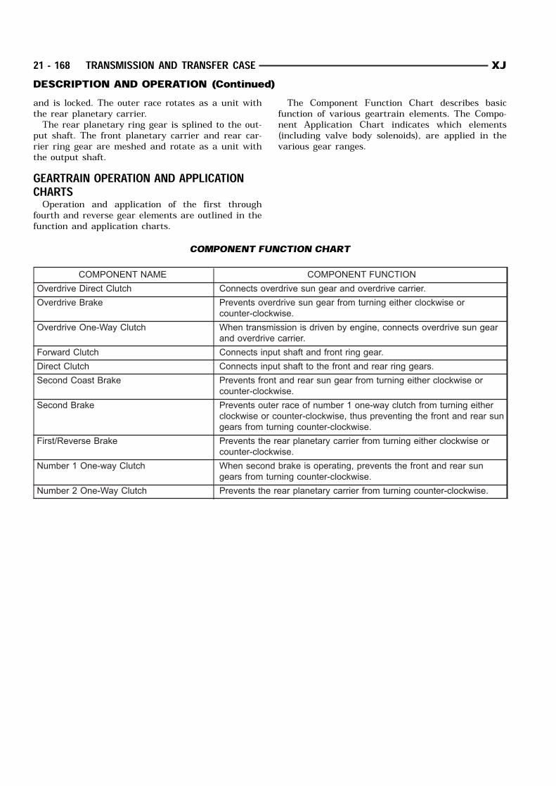
and is locked. The outer race rotates as a unit withthe rear planetary carrier.The rear planetary ring gear is splined to the out-
put shaft. The front planetary carrier and rear car-rier ring gear are meshed and rotate as a unit withthe output shaft.GEARTRAIN OPERATION AND APPLICATIONCHARTSOperation and application of the first through
fourth and reverse gear elements are outlined in thefunction and application charts.
The Component Function Chart describes basicfunction of various geartrain elements. The Compo-nent Application Chart indicates which elements(including valve body solenoids), are applied in thevarious gear ranges.
COMPONENT FUNCTION CHART
COMPONENT NAME COMPONENT FUNCTION
Overdrive Direct Clutch Connects overdrive sun gear and overdrive carrier.
Overdrive Brake Prevents overdrive sun gear from turning either clockwise or
counter-clockwise.
Overdrive One-Way Clutch When transmission is driven by engine, connects overdrive sun gear
and overdrive carrier.
Forward Clutch Connects input shaft and front ring gear.
Direct Clutch Connects input shaft to the front and rear ring gears.
Second Coast Brake Prevents front and rear sun gear from turning either clockwise or
counter-clockwise.
Second Brake Prevents outer race of number 1 one-way clutch from turning either
clockwise or counter-clockwise, thus preventing the front and rear sun
gears from turning counter-clockwise.
First/Reverse Brake Prevents the rear planetary carrier from turning either clockwise or
counter-clockwise.
Number 1 One-way Clutch When second brake is operating, prevents the front and rear sun
gears from turning counter-clockwise.
Number 2 One-Way Clutch Prevents the rear planetary carrier from turning counter-clockwise.
21 - 168 TRANSMISSION AND TRANSFER CASE XJDESCRIPTION AND OPERATION (Continued)
HYDRAULIC SYSTEM
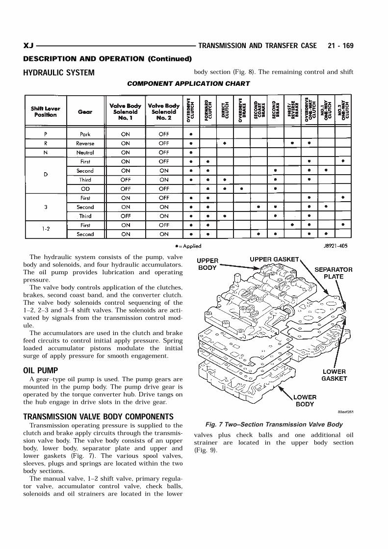
The hydraulic system consists of the pump, valvebody and solenoids, and four hydraulic accumulators.The oil pump provides lubrication and operatingpressure.The valve body controls application of the clutches,
brakes, second coast band, and the converter clutch.The valve body solenoids control sequencing of the1–2, 2–3 and 3–4 shift valves. The solenoids are acti-vated by signals from the transmission control mod-ule.The accumulators are used in the clutch and brake
feed circuits to control initial apply pressure. Springloaded accumulator pistons modulate the initialsurge of apply pressure for smooth engagement.OIL PUMPA gear–type oil pump is used. The pump gears are
mounted in the pump body. The pump drive gear isoperated by the torque converter hub. Drive tangs onthe hub engage in drive slots in the drive gear.TRANSMISSION VALVE BODY COMPONENTSTransmission operating pressure is supplied to the
clutch and brake apply circuits through the transmis-sion valve body. The valve body consists of an upperbody, lower body, separator plate and upper andlower gaskets (Fig. 7). The various spool valves,sleeves, plugs and springs are located within the twobody sections.The manual valve, 1–2 shift valve, primary regula-
tor valve, accumulator control valve, check balls,solenoids and oil strainers are located in the lower
body section (Fig. 8). The remaining control and shift
valves plus check balls and one additional oilstrainer are located in the upper body section(Fig. 9).
COMPONENT APPLICATION CHART
Fig. 7 Two–Section Transmission Valve Body
XJ TRANSMISSION AND TRANSFER CASE 21 - 169DESCRIPTION AND OPERATION (Continued)
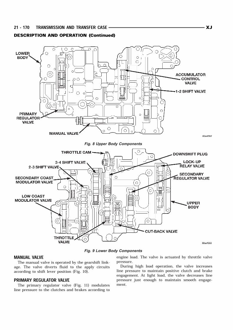
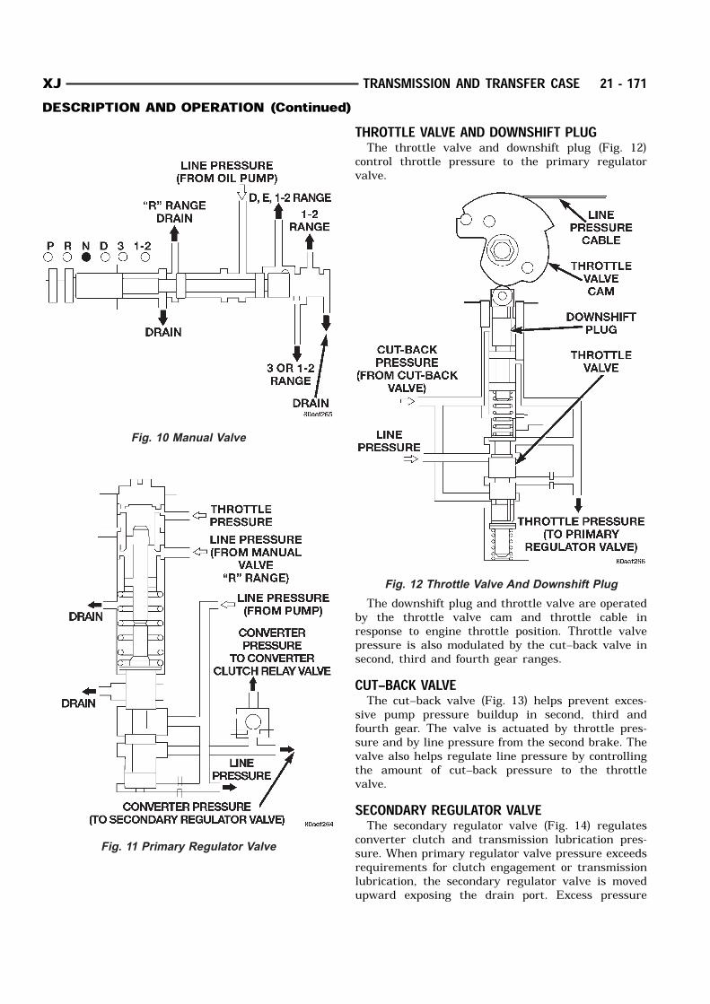
MANUAL VALVEThe manual valve is operated by the gearshift link-
age. The valve diverts fluid to the apply circuitsaccording to shift lever position (Fig. 10).PRIMARY REGULATOR VALVEThe primary regulator valve (Fig. 11) modulates
line pressure to the clutches and brakes according to
engine load. The valve is actuated by throttle valvepressure.During high load operation, the valve increases
line pressure to maintain positive clutch and brakeengagement. At light load, the valve decreases linepressure just enough to maintain smooth engage-ment.
Fig. 8 Upper Body Components
Fig. 9 Lower Body Components
21 - 170 TRANSMISSION AND TRANSFER CASE XJDESCRIPTION AND OPERATION (Continued)
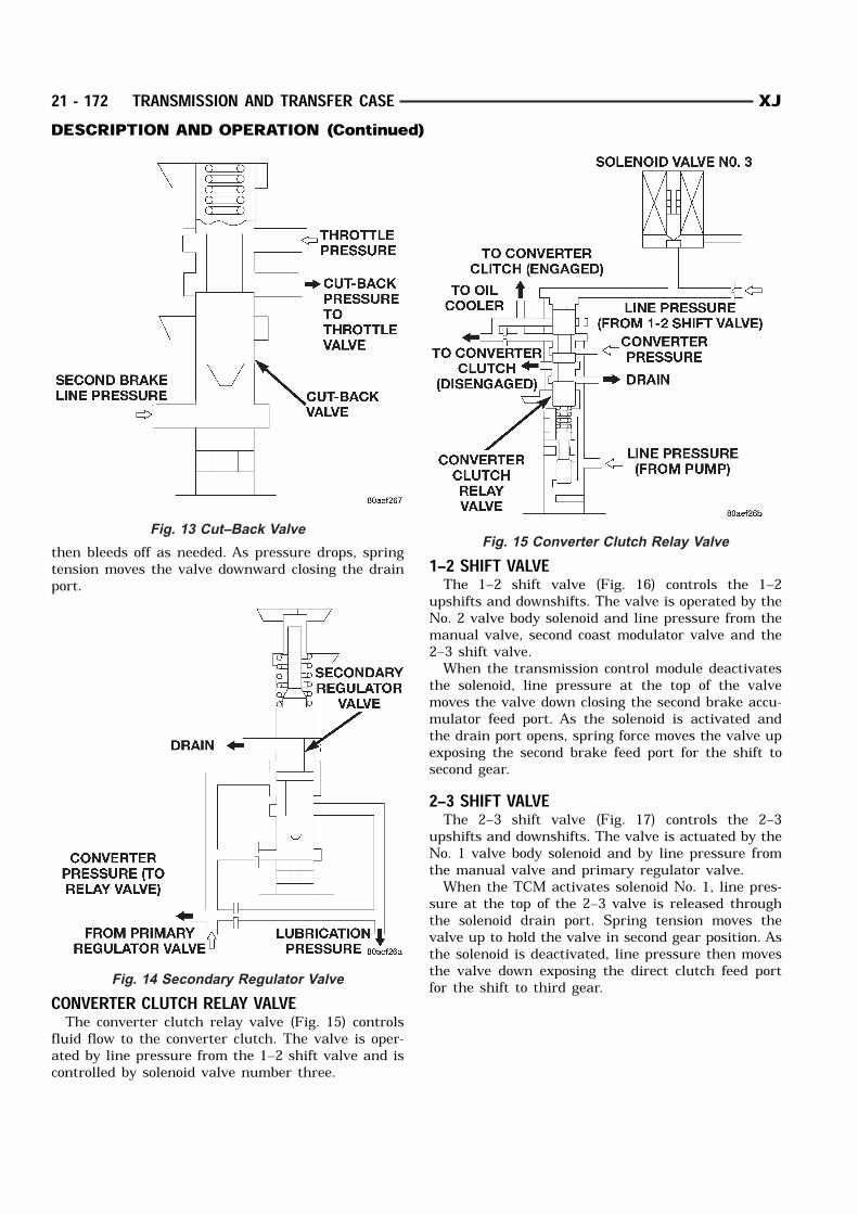
THROTTLE VALVE AND DOWNSHIFT PLUGThe throttle valve and downshift plug (Fig. 12)
control throttle pressure to the primary regulatorvalve.
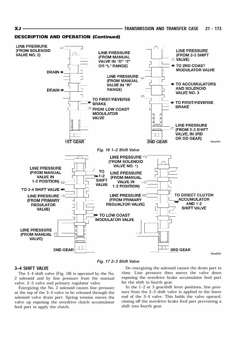
The downshift plug and throttle valve are operatedby the throttle valve cam and throttle cable inresponse to engine throttle position. Throttle valvepressure is also modulated by the cut–back valve insecond, third and fourth gear ranges.CUT–BACK VALVEThe cut–back valve (Fig. 13) helps prevent exces-
sive pump pressure buildup in second, third andfourth gear. The valve is actuated by throttle pres-sure and by line pressure from the second brake. Thevalve also helps regulate line pressure by controllingthe amount of cut–back pressure to the throttlevalve.SECONDARY REGULATOR VALVEThe secondary regulator valve (Fig. 14) regulates
converter clutch and transmission lubrication pres-sure. When primary regulator valve pressure exceedsrequirements for clutch engagement or transmissionlubrication, the secondary regulator valve is movedupward exposing the drain port. Excess pressure
Fig. 10 Manual Valve
Fig. 11 Primary Regulator Valve
Fig. 12 Throttle Valve And Downshift Plug
XJ TRANSMISSION AND TRANSFER CASE 21 - 171DESCRIPTION AND OPERATION (Continued)
then bleeds off as needed. As pressure drops, springtension moves the valve downward closing the drainport.
CONVERTER CLUTCH RELAY VALVEThe converter clutch relay valve (Fig. 15) controls
fluid flow to the converter clutch. The valve is oper-ated by line pressure from the 1–2 shift valve and iscontrolled by solenoid valve number three.
1–2 SHIFT VALVEThe 1–2 shift valve (Fig. 16) controls the 1–2
upshifts and downshifts. The valve is operated by theNo. 2 valve body solenoid and line pressure from themanual valve, second coast modulator valve and the2–3 shift valve.When the transmission control module deactivates
the solenoid, line pressure at the top of the valvemoves the valve down closing the second brake accu-mulator feed port. As the solenoid is activated andthe drain port opens, spring force moves the valve upexposing the second brake feed port for the shift tosecond gear.2–3 SHIFT VALVEThe 2–3 shift valve (Fig. 17) controls the 2–3
upshifts and downshifts. The valve is actuated by theNo. 1 valve body solenoid and by line pressure fromthe manual valve and primary regulator valve.When the TCM activates solenoid No. 1, line pres-
sure at the top of the 2–3 valve is released throughthe solenoid drain port. Spring tension moves thevalve up to hold the valve in second gear position. Asthe solenoid is deactivated, line pressure then movesthe valve down exposing the direct clutch feed portfor the shift to third gear.
Fig. 13 Cut–Back Valve
Fig. 14 Secondary Regulator Valve
Fig. 15 Converter Clutch Relay Valve
21 - 172 TRANSMISSION AND TRANSFER CASE XJDESCRIPTION AND OPERATION (Continued)
3–4 SHIFT VALVEThe 3–4 shift valve (Fig. 18) is operated by the No.
2 solenoid and by line pressure from the manualvalve, 2–3 valve and primary regulator valve.Energizing the No. 2 solenoid causes line pressure
at the top of the 3–4 valve to be released through thesolenoid valve drain port. Spring tension moves thevalve up exposing the overdrive clutch accumulatorfeed port to apply the clutch.
De–energizing the solenoid causes the drain port toclose. Line pressure then moves the valve downexposing the overdrive brake accumulator feed portfor the shift to fourth gear.In the 1–2 or 3 gearshift lever positions, line pres-
sure from the 2–3 shift valve is applied to the lowerend of the 3–4 valve. This holds the valve upward,closing off the overdrive brake feed port preventing ashift into fourth gear.
Fig. 16 1–2 Shift Valve
Fig. 17 2–3 Shift Valve
XJ TRANSMISSION AND TRANSFER CASE 21 - 173DESCRIPTION AND OPERATION (Continued)
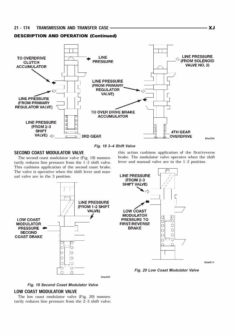
SECOND COAST MODULATOR VALVEThe second coast modulator valve (Fig. 19) momen-
tarily reduces line pressure from the 1–2 shift valve.This cushions application of the second coast brake.The valve is operative when the shift lever and man-ual valve are in the 3 position.
LOW COAST MODULATOR VALVEThe low coast modulator valve (Fig. 20) momen-
tarily reduces line pressure from the 2–3 shift valve;
this action cushions application of the first/reversebrake. The modulator valve operates when the shiftlever and manual valve are in the 1–2 position.
Fig. 18 3–4 Shift Valve
Fig. 19 Second Coast Modulator Valve
Fig. 20 Low Coast Modulator Valve
21 - 174 TRANSMISSION AND TRANSFER CASE XJDESCRIPTION AND OPERATION (Continued)
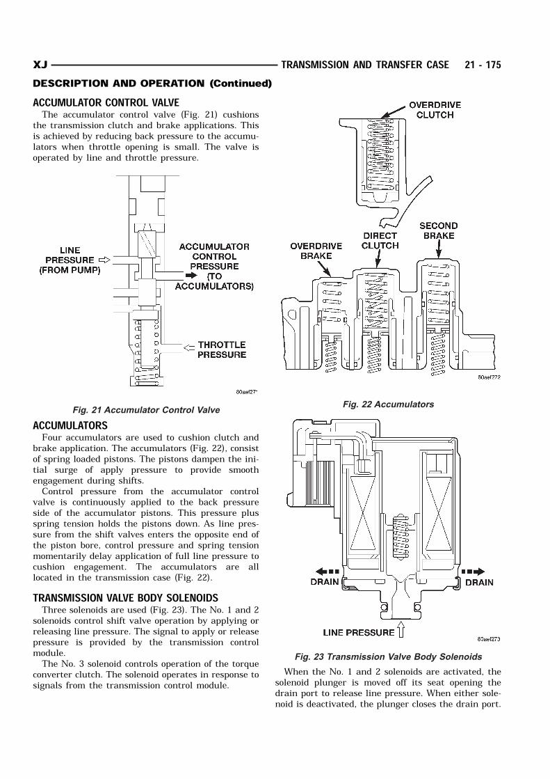
ACCUMULATOR CONTROL VALVEThe accumulator control valve (Fig. 21) cushions
the transmission clutch and brake applications. Thisis achieved by reducing back pressure to the accumu-lators when throttle opening is small. The valve isoperated by line and throttle pressure.
ACCUMULATORSFour accumulators are used to cushion clutch and
brake application. The accumulators (Fig. 22), consistof spring loaded pistons. The pistons dampen the ini-tial surge of apply pressure to provide smoothengagement during shifts.Control pressure from the accumulator control
valve is continuously applied to the back pressureside of the accumulator pistons. This pressure plusspring tension holds the pistons down. As line pres-sure from the shift valves enters the opposite end ofthe piston bore, control pressure and spring tensionmomentarily delay application of full line pressure tocushion engagement. The accumulators are alllocated in the transmission case (Fig. 22).TRANSMISSION VALVE BODY SOLENOIDSThree solenoids are used (Fig. 23). The No. 1 and 2
solenoids control shift valve operation by applying orreleasing line pressure. The signal to apply or releasepressure is provided by the transmission controlmodule.The No. 3 solenoid controls operation of the torque
converter clutch. The solenoid operates in response tosignals from the transmission control module.
When the No. 1 and 2 solenoids are activated, thesolenoid plunger is moved off its seat opening thedrain port to release line pressure. When either sole-noid is deactivated, the plunger closes the drain port.
Fig. 21 Accumulator Control ValveFig. 22 Accumulators
Fig. 23 Transmission Valve Body Solenoids
XJ TRANSMISSION AND TRANSFER CASE 21 - 175DESCRIPTION AND OPERATION (Continued)
The No. 3 solenoid operates in reverse. When thesolenoid is deactivated, the solenoid plunger is movedoff its seat opening the drain port to release linepressure. When the solenoid is activated, the plungercloses the drain port.TRANSMISSION COOLERMAIN COOLERThe transmission main cooler is located in the
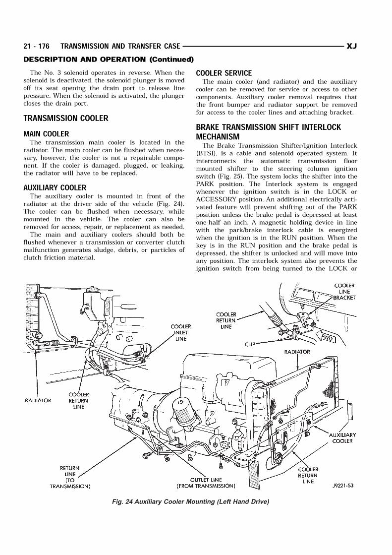
radiator. The main cooler can be flushed when neces-sary, however, the cooler is not a repairable compo-nent. If the cooler is damaged, plugged, or leaking,the radiator will have to be replaced.AUXILIARY COOLERThe auxiliary cooler is mounted in front of the
radiator at the driver side of the vehicle (Fig. 24).The cooler can be flushed when necessary, whilemounted in the vehicle. The cooler can also beremoved for access, repair, or replacement as needed.The main and auxiliary coolers should both be
flushed whenever a transmission or converter clutchmalfunction generates sludge, debris, or particles ofclutch friction material.
COOLER SERVICEThe main cooler (and radiator) and the auxiliary
cooler can be removed for service or access to othercomponents. Auxiliary cooler removal requires thatthe front bumper and radiator support be removedfor access to the cooler lines and attaching bracket.BRAKE TRANSMISSION SHIFT INTERLOCKMECHANISMThe Brake Transmission Shifter/Ignition Interlock
(BTSI), is a cable and solenoid operated system. Itinterconnects the automatic transmission floormounted shifter to the steering column ignitionswitch (Fig. 25). The system locks the shifter into thePARK position. The Interlock system is engagedwhenever the ignition switch is in the LOCK orACCESSORY position. An additional electrically acti-vated feature will prevent shifting out of the PARKposition unless the brake pedal is depressed at leastone-half an inch. A magnetic holding device in linewith the park/brake interlock cable is energizedwhen the ignition is in the RUN position. When thekey is in the RUN position and the brake pedal isdepressed, the shifter is unlocked and will move intoany position. The interlock system also prevents theignition switch from being turned to the LOCK or
Fig. 24 Auxiliary Cooler Mounting (Left Hand Drive)
21 - 176 TRANSMISSION AND TRANSFER CASE XJDESCRIPTION AND OPERATION (Continued)
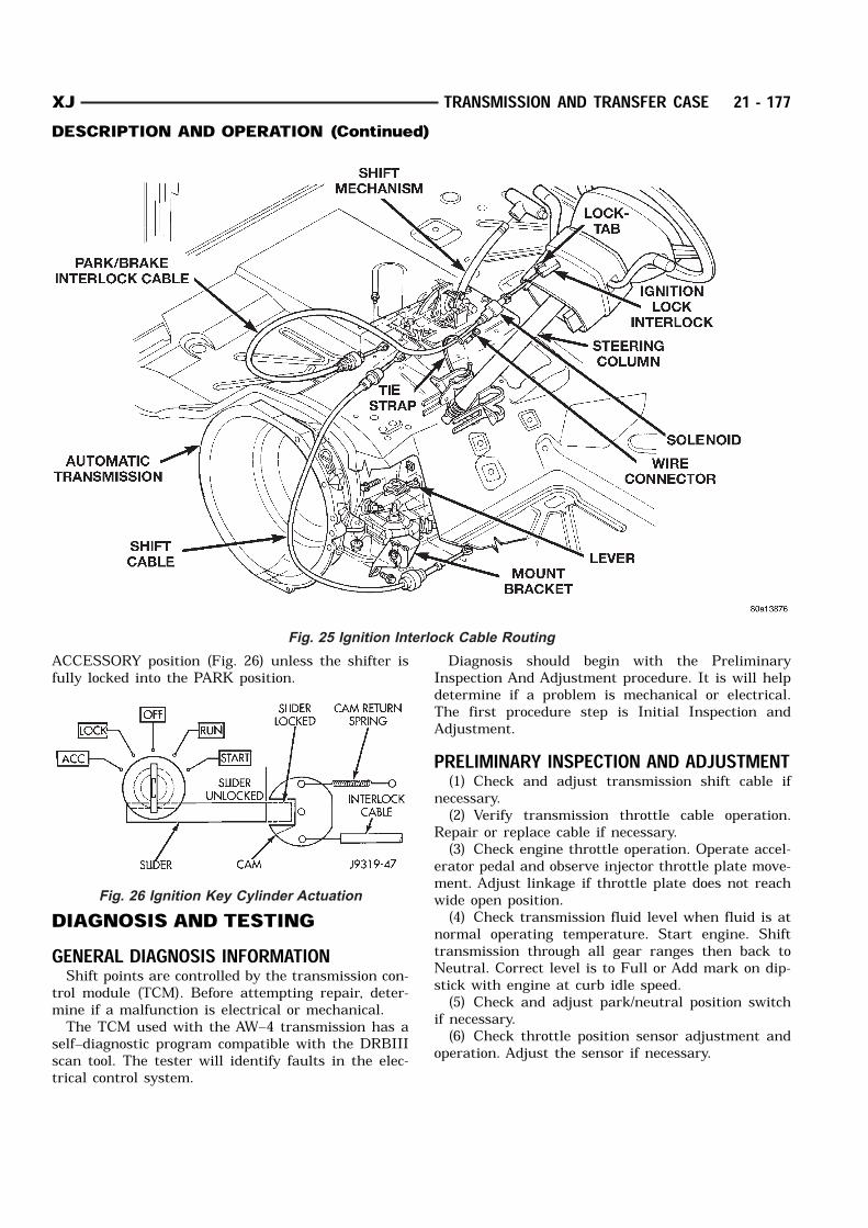
ACCESSORY position (Fig. 26) unless the shifter isfully locked into the PARK position.
DIAGNOSIS AND TESTINGGENERAL DIAGNOSIS INFORMATIONShift points are controlled by the transmission con-
trol module (TCM). Before attempting repair, deter-mine if a malfunction is electrical or mechanical.The TCM used with the AW–4 transmission has a
self–diagnostic program compatible with the DRBIIIscan tool. The tester will identify faults in the elec-trical control system.
Diagnosis should begin with the PreliminaryInspection And Adjustment procedure. It is will helpdetermine if a problem is mechanical or electrical.The first procedure step is Initial Inspection andAdjustment.PRELIMINARY INSPECTION AND ADJUSTMENT(1) Check and adjust transmission shift cable if
necessary.(2) Verify transmission throttle cable operation.
Repair or replace cable if necessary.(3) Check engine throttle operation. Operate accel-
erator pedal and observe injector throttle plate move-ment. Adjust linkage if throttle plate does not reachwide open position.(4) Check transmission fluid level when fluid is at
normal operating temperature. Start engine. Shifttransmission through all gear ranges then back toNeutral. Correct level is to Full or Add mark on dip-stick with engine at curb idle speed.(5) Check and adjust park/neutral position switch
if necessary.(6) Check throttle position sensor adjustment and
operation. Adjust the sensor if necessary.
Fig. 25 Ignition Interlock Cable Routing
Fig. 26 Ignition Key Cylinder Actuation
XJ TRANSMISSION AND TRANSFER CASE 21 - 177DESCRIPTION AND OPERATION (Continued)
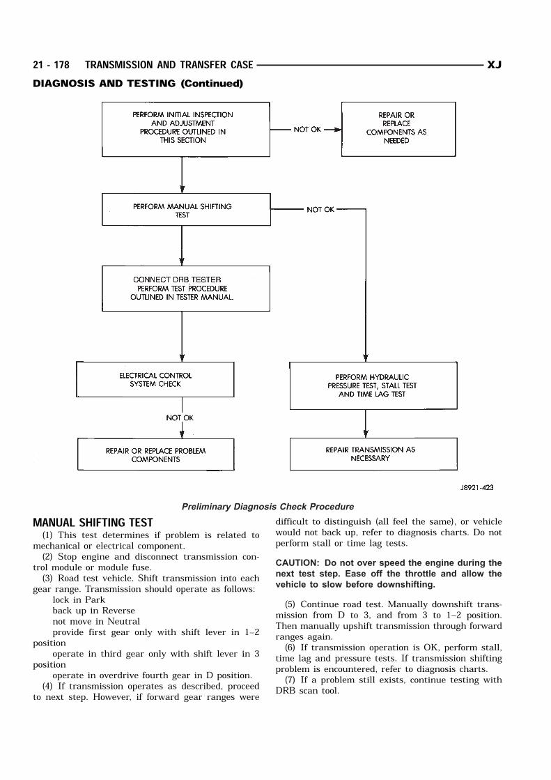
MANUAL SHIFTING TEST(1) This test determines if problem is related to
mechanical or electrical component.(2) Stop engine and disconnect transmission con-
trol module or module fuse.(3) Road test vehicle. Shift transmission into each
gear range. Transmission should operate as follows: lock in Park back up in Reverse not move in Neutral provide first gear only with shift lever in 1–2
position operate in third gear only with shift lever in 3
position operate in overdrive fourth gear in D position.(4) If transmission operates as described, proceed
to next step. However, if forward gear ranges were
difficult to distinguish (all feel the same), or vehiclewould not back up, refer to diagnosis charts. Do notperform stall or time lag tests.CAUTION: Do not over speed the engine during the
next test step. Ease off the throttle and allow the
vehicle to slow before downshifting.
(5) Continue road test. Manually downshift trans-mission from D to 3, and from 3 to 1–2 position.Then manually upshift transmission through forwardranges again.(6) If transmission operation is OK, perform stall,
time lag and pressure tests. If transmission shiftingproblem is encountered, refer to diagnosis charts.(7) If a problem still exists, continue testing with
DRB scan tool.
Preliminary Diagnosis Check Procedure
21 - 178 TRANSMISSION AND TRANSFER CASE XJDIAGNOSIS AND TESTING (Continued)
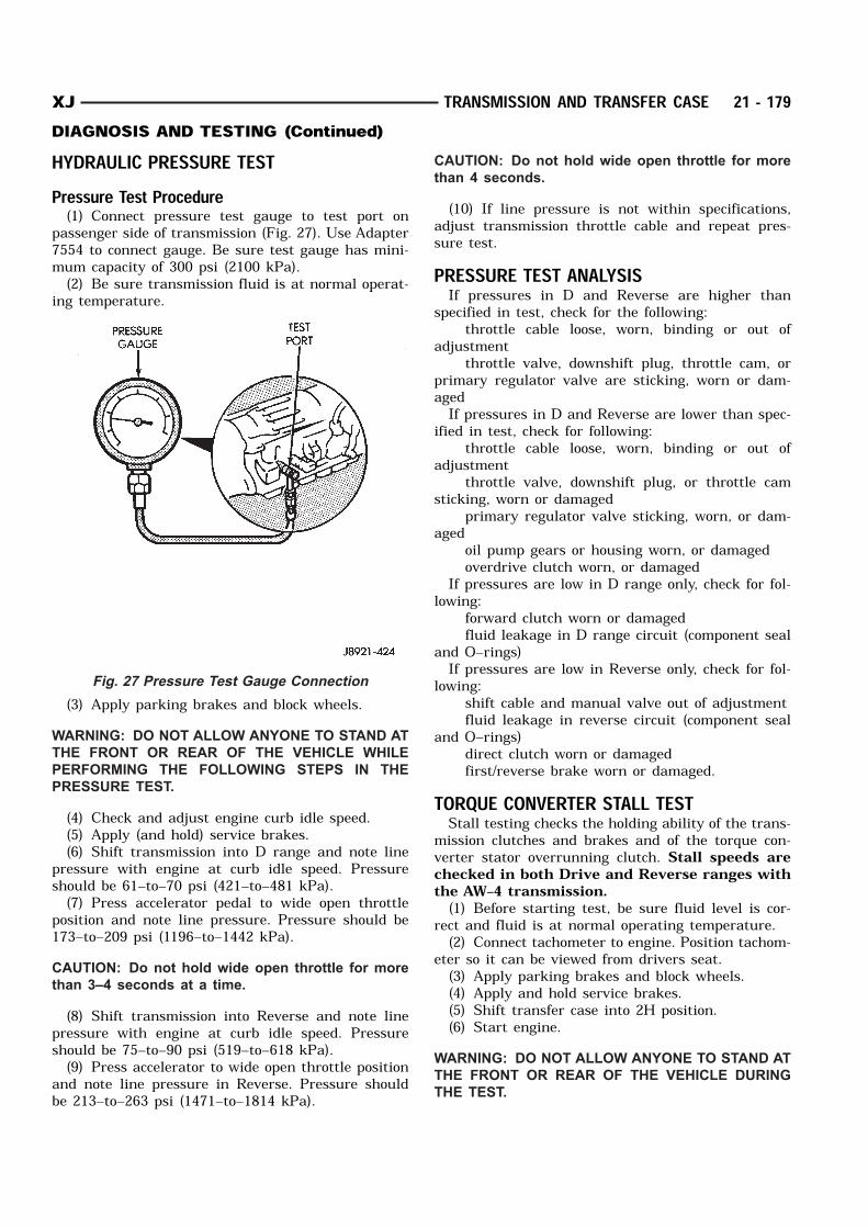
HYDRAULIC PRESSURE TESTPressure Test Procedure(1) Connect pressure test gauge to test port on
passenger side of transmission (Fig. 27). Use Adapter7554 to connect gauge. Be sure test gauge has mini-mum capacity of 300 psi (2100 kPa).(2) Be sure transmission fluid is at normal operat-
ing temperature.
(3) Apply parking brakes and block wheels.WARNING: DO NOT ALLOW ANYONE TO STAND AT
THE FRONT OR REAR OF THE VEHICLE WHILE
PERFORMING THE FOLLOWING STEPS IN THE
PRESSURE TEST.
(4) Check and adjust engine curb idle speed.(5) Apply (and hold) service brakes.(6) Shift transmission into D range and note line
pressure with engine at curb idle speed. Pressureshould be 61–to–70 psi (421–to–481 kPa).(7) Press accelerator pedal to wide open throttle
position and note line pressure. Pressure should be173–to–209 psi (1196–to–1442 kPa).CAUTION: Do not hold wide open throttle for more
than 3–4 seconds at a time.
(8) Shift transmission into Reverse and note linepressure with engine at curb idle speed. Pressureshould be 75–to–90 psi (519–to–618 kPa).(9) Press accelerator to wide open throttle position
and note line pressure in Reverse. Pressure shouldbe 213–to–263 psi (1471–to–1814 kPa).
CAUTION: Do not hold wide open throttle for more
than 4 seconds.
(10) If line pressure is not within specifications,adjust transmission throttle cable and repeat pres-sure test.PRESSURE TEST ANALYSISIf pressures in D and Reverse are higher than
specified in test, check for the following: throttle cable loose, worn, binding or out of
adjustment throttle valve, downshift plug, throttle cam, or
primary regulator valve are sticking, worn or dam-agedIf pressures in D and Reverse are lower than spec-
ified in test, check for following: throttle cable loose, worn, binding or out of
adjustment throttle valve, downshift plug, or throttle cam
sticking, worn or damaged primary regulator valve sticking, worn, or dam-
aged oil pump gears or housing worn, or damaged overdrive clutch worn, or damagedIf pressures are low in D range only, check for fol-
lowing: forward clutch worn or damaged fluid leakage in D range circuit (component seal
and O–rings)If pressures are low in Reverse only, check for fol-
lowing: shift cable and manual valve out of adjustment fluid leakage in reverse circuit (component seal
and O–rings) direct clutch worn or damaged first/reverse brake worn or damaged.
TORQUE CONVERTER STALL TESTStall testing checks the holding ability of the trans-
mission clutches and brakes and of the torque con-verter stator overrunning clutch. Stall speeds arechecked in both Drive and Reverse ranges withthe AW–4 transmission.(1) Before starting test, be sure fluid level is cor-
rect and fluid is at normal operating temperature.(2) Connect tachometer to engine. Position tachom-
eter so it can be viewed from drivers seat.(3) Apply parking brakes and block wheels.(4) Apply and hold service brakes.(5) Shift transfer case into 2H position.(6) Start engine.
WARNING: DO NOT ALLOW ANYONE TO STAND AT
THE FRONT OR REAR OF THE VEHICLE DURING
THE TEST.
Fig. 27 Pressure Test Gauge Connection
XJ TRANSMISSION AND TRANSFER CASE 21 - 179DIAGNOSIS AND TESTING (Continued)
(7) Shift transmission into D range.(8) Open throttle completely and record maximum
engine rpm registered on tachometer. It takes any-where from 4 to 10 seconds to reach maximum rpm.However, once maximum rpm has been achieved, donot hold wide open throttle for more than 3–4seconds.CAUTION: Stalling the converter causes a rapid
increase in fluid temperature. To avoid fluid over-
heating, hold wide open throttle for no more than 4
seconds after reaching peak rpm. In addition, if
more than one stall test is required, run the engine
at 1000 rpm with the transmission in Neutral for at
least 20 seconds to cool the fluid.
(9) Stall speed should be in 2100–2400 rpm rangein Drive.(10) Release throttle, shift transmission into Neu-
tral, and run engine for 20–30 seconds to cool fluid.(11) Shift transmission into Reverse.(12) Repeat stall test.(13) Stall speed in Reverse should also be in 2100–
2400 rpm range.(14) Release accelerator pedal, shift transmission
into Neutral, and run engine for 20–30 seconds tocool fluid.STALL SPEED TEST ANALYSISIf engine rpm is lower than specified in D and
Reverse, check for the following: engine output/performance insufficient stator overrunning clutch in torque converter
not holding if engine speed was 1500 rpm or less.If stall speed in D range is higher than specified,
check for the following: line pressure low forward clutch slipping No. 2 one–way clutch not holding overdrive one–way clutch not holdingIf stall speed in Reverse was higher than specified,
check for the following: line pressure low direct clutch slipping first/ reverse brake slipping overdrive one–way clutch not holdingIf stall speeds were higher than specified in both D
and Reverse, check for the following: low fluid level line pressure low overdrive one–way clutch not holding.
TIME LAG TESTThis test checks general condition of the overdrive
clutch, forward clutch, rear clutch and first/reversebrake. Condition is indicated by the amount of timerequired for clutch/brake engagement with the
engine at curb idle speed. Engagement time is mea-sured for D and Reverse positions. A stop watch isrecommended for test accuracy.TEST PROCEDURE(1) Check and adjust transmission fluid level if
necessary.(2) Bring transmission to normal operating tem-
perature.(3) Apply parking brakes and turn off air condi-
tioning unit.(4) Shift transfer case into 2H range.(5) Start engine and check curb idle speed. Adjust
speed if necessary. Curb idle must be correct toensure accurate test results.(6) Shift transmission into Neutral and set stop
watch.(7) During following test steps, start stop watch as
soon as shift lever reaches D and Reverse ranges.(8) Shift transmission into D range and record
time it takes for engagement. Repeat test two moretimes.(9) Reset stop watch and shift transmission back
to Neutral.(10) Shift transmission into Reverse and record
time it takes for engagement. Repeat test two moretimes.(11) Engagement time in D range should be a
maximum of 1.2 seconds. Engagement time forReverse should be a maximum of 1.5 seconds.TIME LAG TEST ANALYSISIf engagement time is longer than specified for D
range, check for the following: shift cable misadjusted line pressure low forward clutch worn overdrive clutch worn or damaged.If engagement time is longer than specified for
Reverse, check for the following: shift cable misadjusted line pressure low direct clutch worn first/reverse brake worn overdrive clutch worn or damaged.
SERVICE DIAGNOSISTRANSMISSION SOLENOID TESTINGTest solenoid resistance with an ohmmeter. Con-
nect the ohmmeter leads to the solenoid mountingbracket and to the solenoid wire terminal (Fig. 28).Solenoid resistance should be 11–15 ohms. Replace
the solenoid if resistance is above or below the spec-ified range.
21 - 180 TRANSMISSION AND TRANSFER CASE XJDIAGNOSIS AND TESTING (Continued)
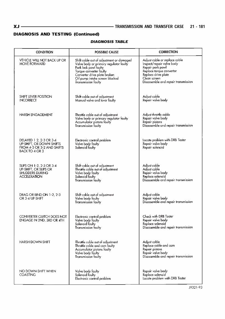
DIAGNOSIS TABLE
XJ TRANSMISSION AND TRANSFER CASE 21 - 181DIAGNOSIS AND TESTING (Continued)
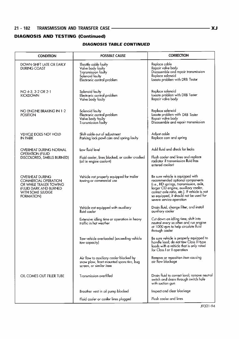
DIAGNOSIS TABLE CONTINUED
21 - 182 TRANSMISSION AND TRANSFER CASE XJDIAGNOSIS AND TESTING (Continued)
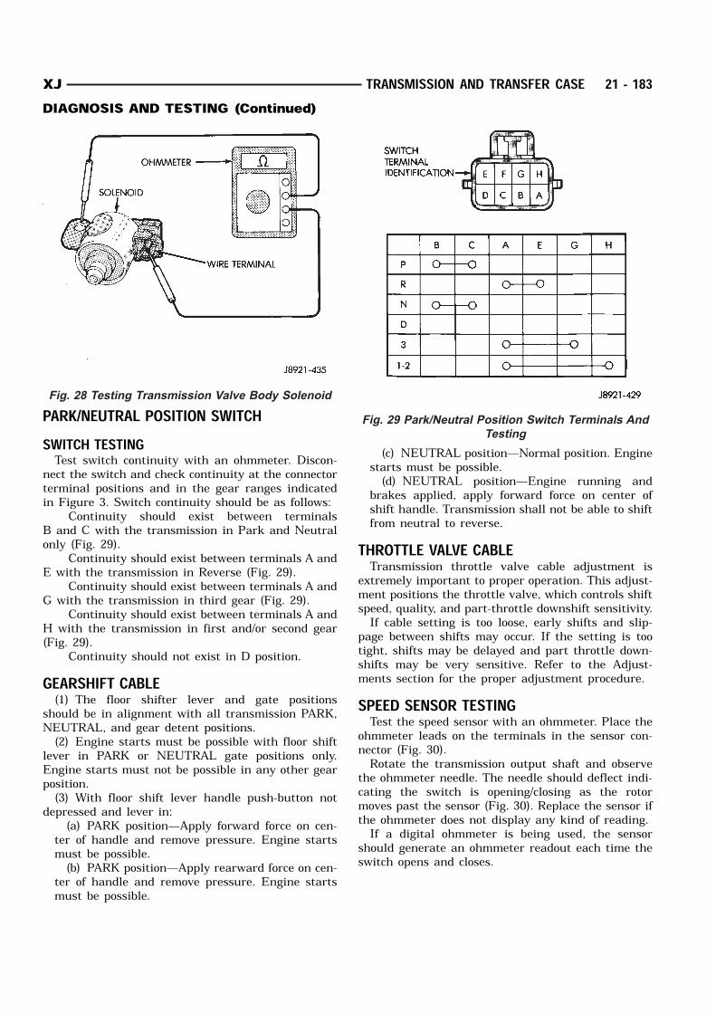
PARK/NEUTRAL POSITION SWITCHSWITCH TESTINGTest switch continuity with an ohmmeter. Discon-
nect the switch and check continuity at the connectorterminal positions and in the gear ranges indicatedin Figure 3. Switch continuity should be as follows:
Continuity should exist between terminalsB and C with the transmission in Park and Neutralonly (Fig. 29).
Continuity should exist between terminals A andE with the transmission in Reverse (Fig. 29).
Continuity should exist between terminals A andG with the transmission in third gear (Fig. 29).
Continuity should exist between terminals A andH with the transmission in first and/or second gear(Fig. 29).
Continuity should not exist in D position.GEARSHIFT CABLE(1) The floor shifter lever and gate positions
should be in alignment with all transmission PARK,NEUTRAL, and gear detent positions.(2) Engine starts must be possible with floor shift
lever in PARK or NEUTRAL gate positions only.Engine starts must not be possible in any other gearposition.(3) With floor shift lever handle push-button not
depressed and lever in:(a) PARK position—Apply forward force on cen-
ter of handle and remove pressure. Engine startsmust be possible.(b) PARK position—Apply rearward force on cen-
ter of handle and remove pressure. Engine startsmust be possible.
(c) NEUTRAL position—Normal position. Enginestarts must be possible.(d) NEUTRAL position—Engine running and
brakes applied, apply forward force on center ofshift handle. Transmission shall not be able to shiftfrom neutral to reverse.
THROTTLE VALVE CABLETransmission throttle valve cable adjustment is
extremely important to proper operation. This adjust-ment positions the throttle valve, which controls shiftspeed, quality, and part-throttle downshift sensitivity.If cable setting is too loose, early shifts and slip-
page between shifts may occur. If the setting is tootight, shifts may be delayed and part throttle down-shifts may be very sensitive. Refer to the Adjust-ments section for the proper adjustment procedure.SPEED SENSOR TESTINGTest the speed sensor with an ohmmeter. Place the
ohmmeter leads on the terminals in the sensor con-nector (Fig. 30).Rotate the transmission output shaft and observe
the ohmmeter needle. The needle should deflect indi-cating the switch is opening/closing as the rotormoves past the sensor (Fig. 30). Replace the sensor ifthe ohmmeter does not display any kind of reading.If a digital ohmmeter is being used, the sensor
should generate an ohmmeter readout each time theswitch opens and closes.
Fig. 28 Testing Transmission Valve Body Solenoid
Fig. 29 Park/Neutral Position Switch Terminals And
Testing
XJ TRANSMISSION AND TRANSFER CASE 21 - 183DIAGNOSIS AND TESTING (Continued)
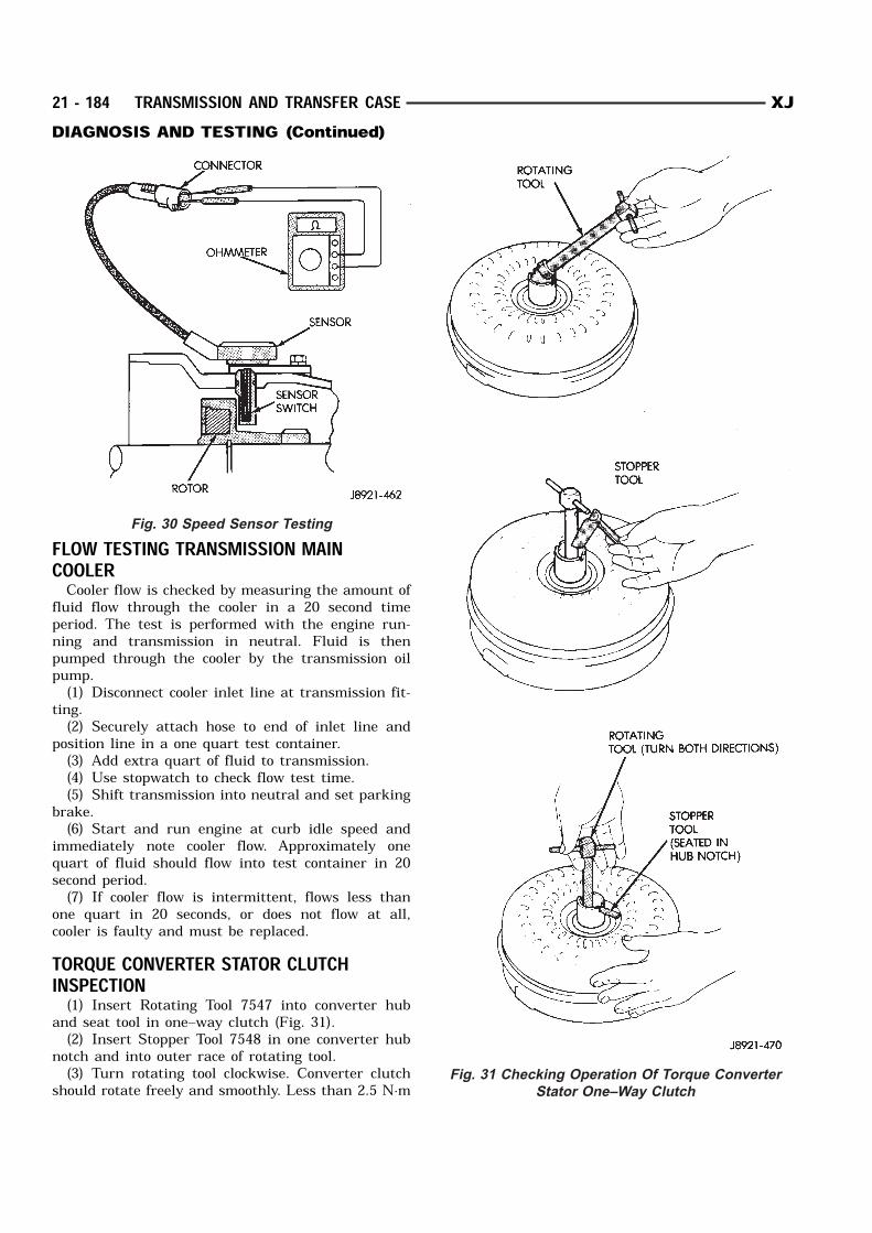
FLOW TESTING TRANSMISSION MAINCOOLERCooler flow is checked by measuring the amount of
fluid flow through the cooler in a 20 second timeperiod. The test is performed with the engine run-ning and transmission in neutral. Fluid is thenpumped through the cooler by the transmission oilpump.(1) Disconnect cooler inlet line at transmission fit-
ting.(2) Securely attach hose to end of inlet line and
position line in a one quart test container.(3) Add extra quart of fluid to transmission.(4) Use stopwatch to check flow test time.(5) Shift transmission into neutral and set parking
brake.(6) Start and run engine at curb idle speed and
immediately note cooler flow. Approximately onequart of fluid should flow into test container in 20second period.(7) If cooler flow is intermittent, flows less than
one quart in 20 seconds, or does not flow at all,cooler is faulty and must be replaced.TORQUE CONVERTER STATOR CLUTCHINSPECTION(1) Insert Rotating Tool 7547 into converter hub
and seat tool in one–way clutch (Fig. 31).(2) Insert Stopper Tool 7548 in one converter hub
notch and into outer race of rotating tool.(3) Turn rotating tool clockwise. Converter clutch
should rotate freely and smoothly. Less than 2.5 N·m
Fig. 30 Speed Sensor Testing
Fig. 31 Checking Operation Of Torque Converter
Stator One–Way Clutch
21 - 184 TRANSMISSION AND TRANSFER CASE XJDIAGNOSIS AND TESTING (Continued)

(22 in. lbs.) of torque should be required to rotateclutch in clockwise direction.(4) Turn rotating tool in counterclockwise direc-
tion. Converter clutch should lock.(5) Replace converter if clutch binds or will not
lock.
SERVICE PROCEDURESCHECKING FLUID LEVEL(1) Be sure transmission fluid is at normal operat-
ing temperature. Normal operating temperature isreached after approximately 15 miles (25 km) ofoperation.(2) Position vehicle on level surface. This is impor-
tant for an accurate fluid level check.(3) Shift transmission through all gear ranges and
back to Park.(4) Apply parking brakes.(5) Verify that transmission is in Park.(6) Wipe off dipstick handle to prevent dirt from
entering fill tube. Then remove dipstick and checkfluid level and condition.(7) Correct fluid level is to FULL mark on dip-
stick when fluid is at normal operating temper-ature (Fig. 32).
(8) If fluid level is low, top off level with MoparDexron IIE/Mercon. Mopar Dexron II can be used butonly if Mercon is not available. Do not overfilltransmission. Add only enough fluid to bringlevel to Full mark.(9) If too much fluid was added, excess amount can
be removed with suction gun and appropriate diame-ter plastic tubing. Tubing only has to be long enoughto extend into oil pan.CHECKING FLUID CONDITIONInspect the appearance of the fluid during the fluid
level check. Fluid color should range from dark red topink and be free of foreign material, or particles. Ifthe fluid is dark brown or black in color and smellsburnt, the fluid has been overheated and must bechanged.
Transmission operation should also be checked ifthe fluid is severely discolored and contains quanti-ties of foreign material, metal particles, or clutch discfriction material.A small quantity of friction material or metal
particles in the oil pan is normal. The particlesare usually generated during the break–inperiod and indicate normal seating of the vari-ous transmission components.REFILLING AFTER OVERHAUL OR FLUID/FILTER CHANGEThe best way to refill the transmission after a fluid
change or overhaul is as follows:(1) If transmission has been overhauled, install
transmission in vehicle.(2) Remove dipstick and insert clean funnel in
transmission fill tube.(3) Add following initial quantity of Mopar Dexron
IIE/Mercon to transmission:(4) If fluid/filter change was performed, add 4
pints (2 quarts) of fluid to transmission.(a) If transmission was completely overhauled
and torque converter was replaced or drained, add10 pints (5 quarts) of fluid to transmission.(b) Remove funnel and install dipstick.
(5) Operate vehicle until fluid reaches normaloperating temperature.(6) Apply parking brakes.(7) Let engine run at normal curb idle speed, apply
service brakes. Then shift transmission through allgear ranges and back to PARK (leave engine run-ning).(8) Remove dipstick and check fluid level. Add only
enough fluid to bring level to Full mark on dipstick.Do not overfill. If too much fluid is added, excessamount can be removed with suction gun andplastic tubing. Tubing only has to be longenough to extend into oil pan.(9) When fluid level is correct, shut engine off,
release park brake, remove funnel, and reseat dip-stick in fill tube.TRANSMISSION CONTROL MODULE (TCM)SERVICEUse the DRB scan tool to diagnose transmission
control module function whenever a fault is sus-pected. Replace the module only when the scan toolindicates the module is actually faulty.OIL PUMP VOLUME CHECKAfter the new or repaired transmission has been
installed, fill to the proper level with Mopar ATFPLUS 3 (Type 7176) automatic transmission fluid.The volume should be checked using the followingprocedure:
Fig. 32 Transmission Fluid Level
XJ TRANSMISSION AND TRANSFER CASE 21 - 185DIAGNOSIS AND TESTING (Continued)

(1) Disconnect the From cooler line at the trans-mission and place a collecting container under thedisconnected line.CAUTION: With the fluid set at the proper level,
fluid collection should not exceed (1) quart or inter-
nal damage to the transmission may occur.
(2) Run the engine at curb idle speed , with theshift selector in neutral.(3) If fluid flow is intermittent or it takes more
than 20 seconds to collect one quart of ATF PLUS 3,disconnect the To Cooler line at the transaxle.(4) Refill the transaxle to proper level and recheck
pump volume.(5) If flow is found to be within acceptable limits,
replace the cooler. Then fill transmission to theproper level, using Mopar ATF PLUS 3 (Type 7176)automatic transmission fluid.(6) If fluid flow is still found to be inadequate,
check the line pressure using the Transaxle Hydrau-lic Pressure Test procedure.FLUSHING COOLERS AND TUBESWhen a transmission failure has contaminated the
fluid, the oil cooler(s) must be flushed. The torqueconverter must also be replaced. This will insure thatmetal particles or sludged oil are not later trans-ferred back into the reconditioned (or replaced) trans-mission.The only recommended procedure for flushing cool-
ers and lines is to use Tool 6906 Cooler Flusher.WARNING: WEAR PROTECTIVE EYEWEAR THAT
MEETS THE REQUIREMENTS OF OSHA AND ANSI
Z87.1–1968. WEAR STANDARD INDUSTRIAL RUB-
BER GLOVES.
KEEP LIGHTED CIGARETTES, SPARKS, FLAMES,
AND OTHER IGNITION SOURCES AWAY FROM THE
AREA TO PREVENT THE IGNITION OF COMBUSTI-
BLE LIQUIDS AND GASES. KEEP A CLASS (B) FIRE
EXTINGUISHER IN THE AREA WHERE THE
FLUSHER WILL BE USED.
KEEP THE AREA WELL VENTILATED.
DO NOT LET FLUSHING SOLVENT COME IN CON-
TACT WITH YOUR EYES OR SKIN: IF EYE CONTAM-
INATION OCCURS, FLUSH EYES WITH WATER FOR
15 TO 20 SECONDS. REMOVE CONTAMINATED
CLOTHING AND WASH AFFECTED SKIN WITH
SOAP AND WATER. SEEK MEDICAL ATTENTION.
COOLER FLUSH USING TOOL 6906(1) Remove cover plate filler plug on Tool 6906.
Fill reservoir 1/2 to 3/4 full of fresh flushing solution.Flushing solvents are petroleum based solutions gen-erally used to clean automatic transmission compo-
nents. DO NOT use solvents containing acids, water,gasoline, or any other corrosive liquids.(2) Reinstall filler plug on Tool 6906.(3) Verify pump power switch is turned OFF. Con-
nect red alligator clip to positive (+) battery post.Connect black (-) alligator clip to a good ground.(4) Disconnect the cooler lines at the transmission.
NOTE: When flushing transmission cooler and
lines, ALWAYS reverse flush.
NOTE: The converter drainback valve must be
removed and an appropriate replacement hose
installed to bridge the space between the transmis-
sion cooler line and the cooler fitting. Failure to
remove the drainback valve will preventreverse
flushing the system.
(5) Connect the BLUE pressure line to the OUT-LET (From) cooler line.(6) Connect the CLEAR return line to the INLET
(To) cooler line(7) Turn pump ON for two to three minutes to
flush cooler(s) and lines. Monitor pressure readingsand clear return lines. Pressure readings should sta-bilize below 20 psi. for vehicles equipped with a sin-gle cooler and 30 psi. for vehicles equipped with dualcoolers. If flow is intermittent or exceeds these pres-sures, replace cooler.(8) Turn pump OFF.(9) Disconnect CLEAR suction line from reservoir
at cover plate. Disconnect CLEAR return line atcover plate, and place it in a drain pan.(10) Turn pump ON for 30 seconds to purge flush-
ing solution from cooler and lines. Turn pump OFF.(11) Place CLEAR suction line into a one quart
container of Mopar ATF Plus 3, type 7176 automatictransmission fluid.(12) Turn pump ON until all transmission fluid is
removed from the one quart container and lines. Thispurges any residual cleaning solvent from the trans-mission cooler and lines. Turn pump OFF.(13) Disconnect alligator clips from battery. Recon-
nect flusher lines to cover plate, and remove flushingadapters from cooler lines.ALUMINUM THREAD REPAIRDamaged or worn threads in the aluminum trans-
mission case and valve body can be repaired by theuse of Heli-Coils, or equivalent. This repair consistsof drilling out the worn-out damaged threads. Thentap the hole with a special Heli-Coil tap, or equiva-lent, and installing a Heli-Coil insert, or equivalent,into the hole. This brings the hole back to its originalthread size.
21 - 186 TRANSMISSION AND TRANSFER CASE XJSERVICE PROCEDURES (Continued)
Heli-Coil, or equivalent, tools and inserts arereadily available from most automotive parts suppli-ers.
REMOVAL AND INSTALLATIONTRANSMISSION AND TORQUE CONVERTERREMOVAL(1) Raise vehicle.(2) Drain transmission fluid and reinstall oil pan
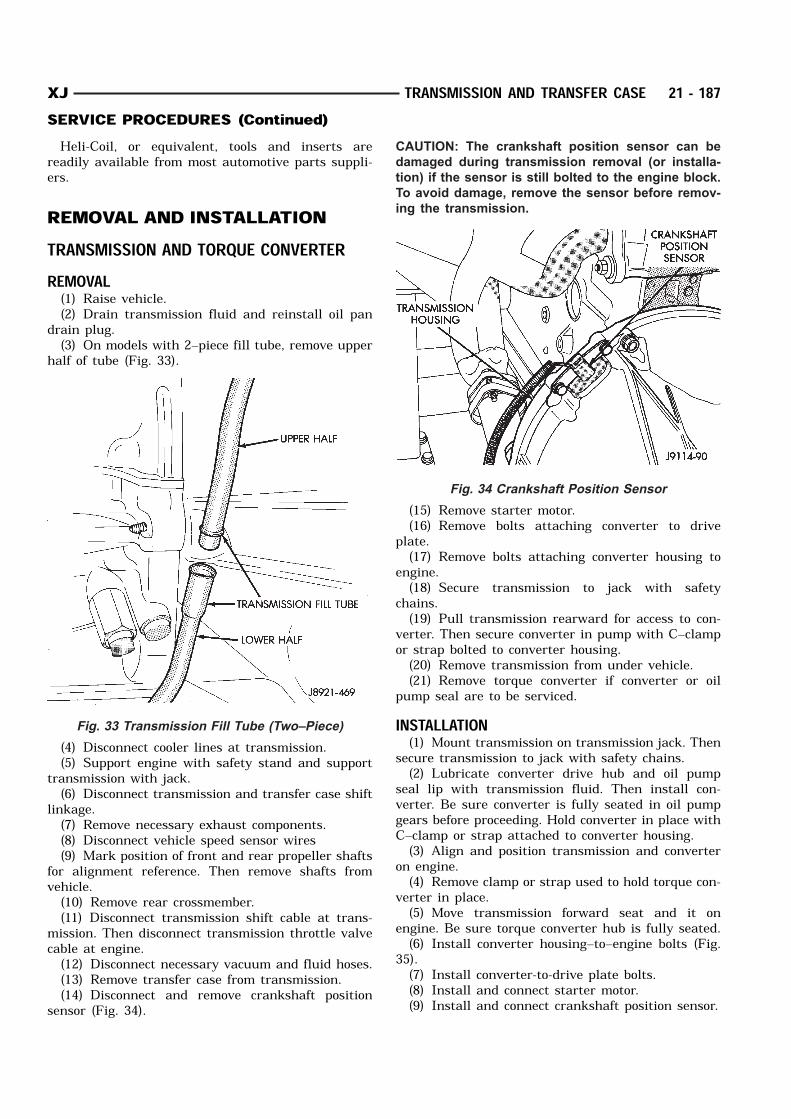
drain plug.(3) On models with 2–piece fill tube, remove upper
half of tube (Fig. 33).
(4) Disconnect cooler lines at transmission.(5) Support engine with safety stand and support
transmission with jack.(6) Disconnect transmission and transfer case shift
linkage.(7) Remove necessary exhaust components.(8) Disconnect vehicle speed sensor wires(9) Mark position of front and rear propeller shafts
for alignment reference. Then remove shafts fromvehicle.(10) Remove rear crossmember.(11) Disconnect transmission shift cable at trans-
mission. Then disconnect transmission throttle valvecable at engine.(12) Disconnect necessary vacuum and fluid hoses.(13) Remove transfer case from transmission.(14) Disconnect and remove crankshaft position
sensor (Fig. 34).
CAUTION: The crankshaft position sensor can be
damaged during transmission removal (or installa-
tion) if the sensor is still bolted to the engine block.
To avoid damage, remove the sensor before remov-
ing the transmission.
(15) Remove starter motor.(16) Remove bolts attaching converter to drive
plate.(17) Remove bolts attaching converter housing to
engine.(18) Secure transmission to jack with safety
chains.(19) Pull transmission rearward for access to con-
verter. Then secure converter in pump with C–clampor strap bolted to converter housing.(20) Remove transmission from under vehicle.(21) Remove torque converter if converter or oil
pump seal are to be serviced.INSTALLATION(1) Mount transmission on transmission jack. Then
secure transmission to jack with safety chains.(2) Lubricate converter drive hub and oil pump
seal lip with transmission fluid. Then install con-verter. Be sure converter is fully seated in oil pumpgears before proceeding. Hold converter in place withC–clamp or strap attached to converter housing.(3) Align and position transmission and converter
on engine.(4) Remove clamp or strap used to hold torque con-
verter in place.(5) Move transmission forward seat and it on
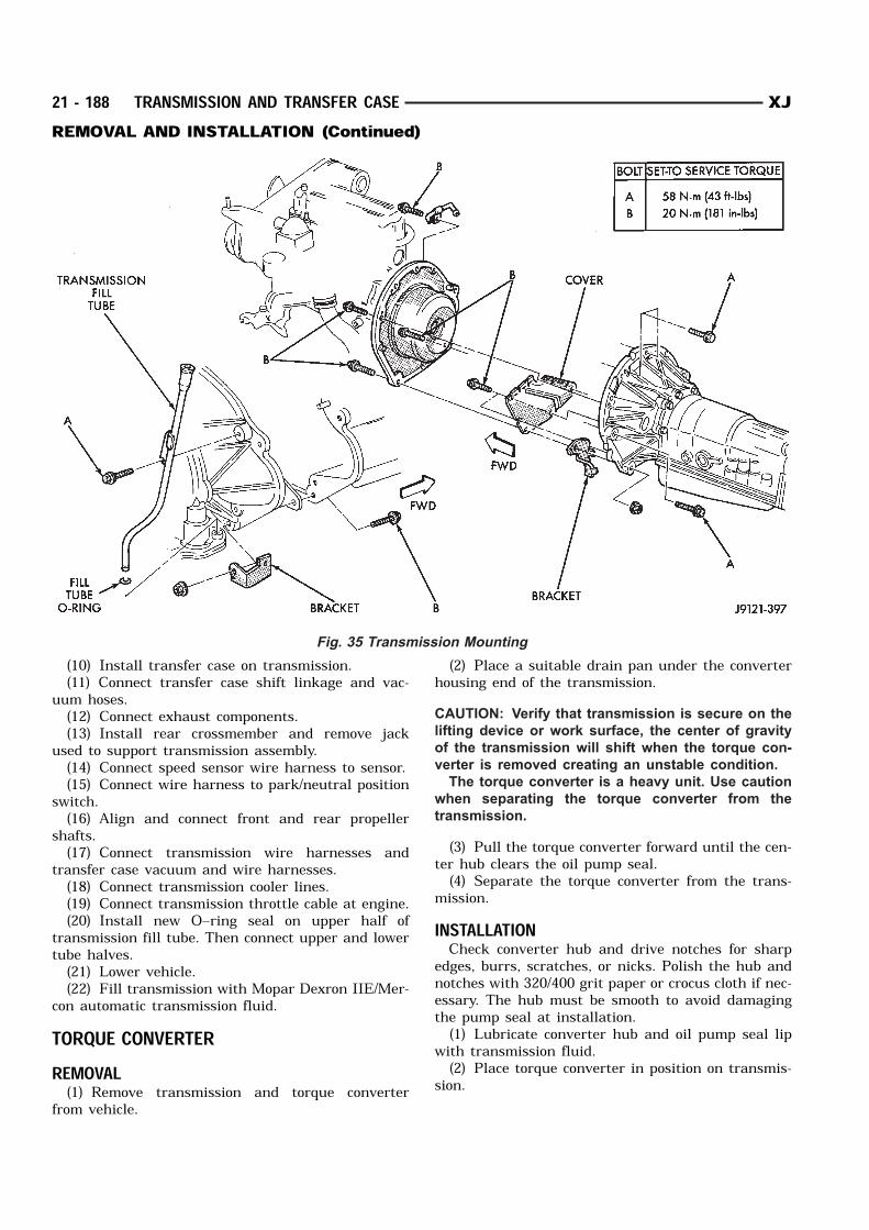
engine. Be sure torque converter hub is fully seated.(6) Install converter housing–to–engine bolts (Fig.
35).(7) Install converter-to-drive plate bolts.(8) Install and connect starter motor.(9) Install and connect crankshaft position sensor.
Fig. 33 Transmission Fill Tube (Two–Piece)
Fig. 34 Crankshaft Position Sensor
XJ TRANSMISSION AND TRANSFER CASE 21 - 187SERVICE PROCEDURES (Continued)
(10) Install transfer case on transmission.(11) Connect transfer case shift linkage and vac-
uum hoses.(12) Connect exhaust components.(13) Install rear crossmember and remove jack
used to support transmission assembly.(14) Connect speed sensor wire harness to sensor.(15) Connect wire harness to park/neutral position
switch.(16) Align and connect front and rear propeller
shafts.(17) Connect transmission wire harnesses and
transfer case vacuum and wire harnesses.(18) Connect transmission cooler lines.(19) Connect transmission throttle cable at engine.(20) Install new O–ring seal on upper half of
transmission fill tube. Then connect upper and lowertube halves.(21) Lower vehicle.(22) Fill transmission with Mopar Dexron IIE/Mer-
con automatic transmission fluid.TORQUE CONVERTERREMOVAL(1) Remove transmission and torque converter
from vehicle.
(2) Place a suitable drain pan under the converterhousing end of the transmission.CAUTION: Verify that transmission is secure on the
lifting device or work surface, the center of gravity
of the transmission will shift when the torque con-
verter is removed creating an unstable condition.
The torque converter is a heavy unit. Use caution
when separating the torque converter from the
transmission.
(3) Pull the torque converter forward until the cen-ter hub clears the oil pump seal.(4) Separate the torque converter from the trans-
mission.INSTALLATIONCheck converter hub and drive notches for sharp
edges, burrs, scratches, or nicks. Polish the hub andnotches with 320/400 grit paper or crocus cloth if nec-essary. The hub must be smooth to avoid damagingthe pump seal at installation.(1) Lubricate converter hub and oil pump seal lip
with transmission fluid.(2) Place torque converter in position on transmis-
sion.
Fig. 35 Transmission Mounting
21 - 188 TRANSMISSION AND TRANSFER CASE XJREMOVAL AND INSTALLATION (Continued)
CAUTION: Do not damage oil pump seal or bushing
while inserting torque converter into the front of the
transmission.
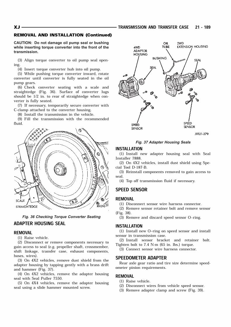
(3) Align torque converter to oil pump seal open-ing.(4) Insert torque converter hub into oil pump.(5) While pushing torque converter inward, rotate
converter until converter is fully seated in the oilpump gears.(6) Check converter seating with a scale and
straightedge (Fig. 36). Surface of converter lugsshould be 1/2 in. to rear of straightedge when con-verter is fully seated.(7) If necessary, temporarily secure converter with
C-clamp attached to the converter housing.(8) Install the transmission in the vehicle.(9) Fill the transmission with the recommended
fluid.
ADAPTER HOUSING SEALREMOVAL(1) Raise vehicle.(2) Disconnect or remove components necessary to
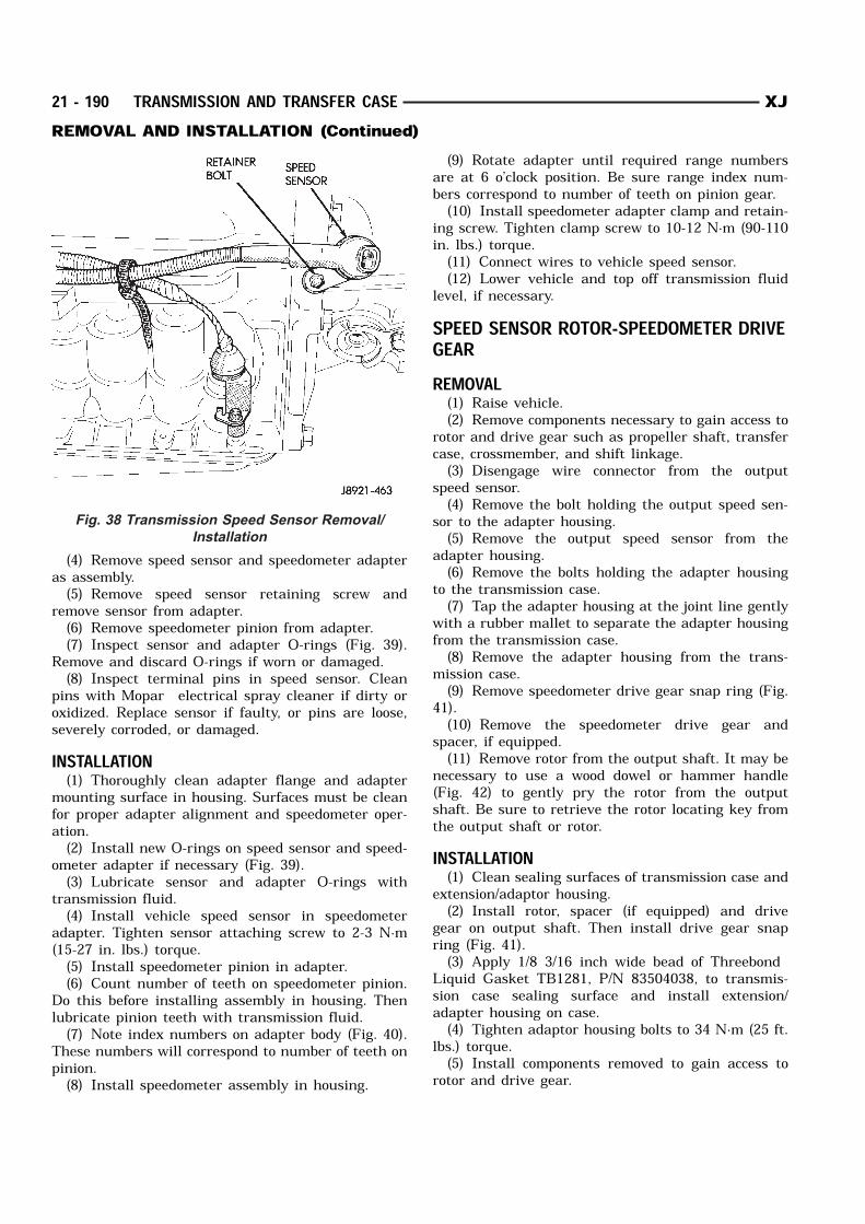
gain access to seal (e.g. propeller shaft, crossmember,shift linkage, transfer case, exhaust components,hoses, wires).(3) On 4X2 vehicles, remove dust shield from the
adapter housing by tapping gently with a brass driftand hammer (Fig. 37).(4) On 4X2 vehicles, remove the adapter housing
seal with Seal Puller 7550.(5) On 4X4 vehicles, remove the adapter housing
seal using a slide hammer mounted screw.
INSTALLATION(1) Install new adapter housing seal with Seal
Installer 7888.(2) On 4X2 vehicles, install dust shield using Spe-
cial Tool D-187-B.(3) Reinstall components removed to gain access to
seal.(4) Top off transmission fluid if necessary.
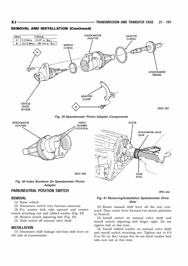
SPEED SENSORREMOVAL(1) Disconnect sensor wire harness connector.(2) Remove sensor retainer bolt and remove sensor
(Fig. 38).(3) Remove and discard speed sensor O–ring.
INSTALLATION(1) Install new O–ring on speed sensor and install
sensor in transmission case.(2) Install sensor bracket and retainer bolt.
Tighten bolt to 7.4 N·m (65 in. lbs.) torque.(3) Connect sensor wire harness connector.
SPEEDOMETER ADAPTERRear axle gear ratio and tire size determine speed-
ometer pinion requirements.REMOVAL(1) Raise vehicle.(2) Disconnect wires from vehicle speed sensor.(3) Remove adapter clamp and screw (Fig. 39).
Fig. 36 Checking Torque Converter Seating
Fig. 37 Adapter Housing Seals
XJ TRANSMISSION AND TRANSFER CASE 21 - 189REMOVAL AND INSTALLATION (Continued)
(4) Remove speed sensor and speedometer adapteras assembly.(5) Remove speed sensor retaining screw and
remove sensor from adapter.(6) Remove speedometer pinion from adapter.(7) Inspect sensor and adapter O-rings (Fig. 39).
Remove and discard O-rings if worn or damaged.(8) Inspect terminal pins in speed sensor. Clean
pins with Mopar electrical spray cleaner if dirty oroxidized. Replace sensor if faulty, or pins are loose,severely corroded, or damaged.INSTALLATION(1) Thoroughly clean adapter flange and adapter
mounting surface in housing. Surfaces must be cleanfor proper adapter alignment and speedometer oper-ation.(2) Install new O-rings on speed sensor and speed-
ometer adapter if necessary (Fig. 39).(3) Lubricate sensor and adapter O-rings with
transmission fluid.(4) Install vehicle speed sensor in speedometer
adapter. Tighten sensor attaching screw to 2-3 N·m(15-27 in. lbs.) torque.(5) Install speedometer pinion in adapter.(6) Count number of teeth on speedometer pinion.
Do this before installing assembly in housing. Thenlubricate pinion teeth with transmission fluid.(7) Note index numbers on adapter body (Fig. 40).
These numbers will correspond to number of teeth onpinion.(8) Install speedometer assembly in housing.
(9) Rotate adapter until required range numbersare at 6 o’clock position. Be sure range index num-bers correspond to number of teeth on pinion gear.(10) Install speedometer adapter clamp and retain-
ing screw. Tighten clamp screw to 10-12 N·m (90-110in. lbs.) torque.(11) Connect wires to vehicle speed sensor.(12) Lower vehicle and top off transmission fluid
level, if necessary.SPEED SENSOR ROTOR-SPEEDOMETER DRIVEGEARREMOVAL(1) Raise vehicle.(2) Remove components necessary to gain access to
rotor and drive gear such as propeller shaft, transfercase, crossmember, and shift linkage.(3) Disengage wire connector from the output
speed sensor.(4) Remove the bolt holding the output speed sen-
sor to the adapter housing.(5) Remove the output speed sensor from the
adapter housing.(6) Remove the bolts holding the adapter housing
to the transmission case.(7) Tap the adapter housing at the joint line gently
with a rubber mallet to separate the adapter housingfrom the transmission case.(8) Remove the adapter housing from the trans-
mission case.(9) Remove speedometer drive gear snap ring (Fig.
41).(10) Remove the speedometer drive gear and
spacer, if equipped.(11) Remove rotor from the output shaft. It may be
necessary to use a wood dowel or hammer handle(Fig. 42) to gently pry the rotor from the outputshaft. Be sure to retrieve the rotor locating key fromthe output shaft or rotor.INSTALLATION(1) Clean sealing surfaces of transmission case and
extension/adaptor housing.(2) Install rotor, spacer (if equipped) and drive
gear on output shaft. Then install drive gear snapring (Fig. 41).(3) Apply 1/8 3/16 inch wide bead of Threebond
Liquid Gasket TB1281, P/N 83504038, to transmis-sion case sealing surface and install extension/adapter housing on case.(4) Tighten adaptor housing bolts to 34 N·m (25 ft.
lbs.) torque.(5) Install components removed to gain access to
rotor and drive gear.
Fig. 38 Transmission Speed Sensor Removal/
Installation
21 - 190 TRANSMISSION AND TRANSFER CASE XJREMOVAL AND INSTALLATION (Continued)
PARK/NEUTRAL POSITION SWITCHREMOVAL(1) Raise vehicle.(2) Disconnect switch wire harness connector.(3) Pry washer lock tabs upward and remove
switch attaching nut and tabbed washer (Fig. 43).(4) Remove switch adjusting bolt (Fig. 43).(5) Slide switch off manual valve shaft.
INSTALLATION(1) Disconnect shift linkage rod from shift lever on
left side of transmission.
(2) Rotate manual shift lever all the way rear-ward. Then rotate lever forward two detent positionsto Neutral.(3) Install switch on manual valve shaft and
install switch adjusting bolt finger tight. Do nottighten bolt at this time.(4) Install tabbed washer on manual valve shaft
and install switch attaching nut. Tighten nut to 6.9N·m (61 in. lbs.) torque but do not bend washer locktabs over nut at this time.
Fig. 39 Speedometer Pinion Adapter Components
Fig. 40 Index Numbers On Speedometer Pinion
Adapter
Fig. 41 Removing/Installation Speedometer Drive
Gear
XJ TRANSMISSION AND TRANSFER CASE 21 - 191REMOVAL AND INSTALLATION (Continued)
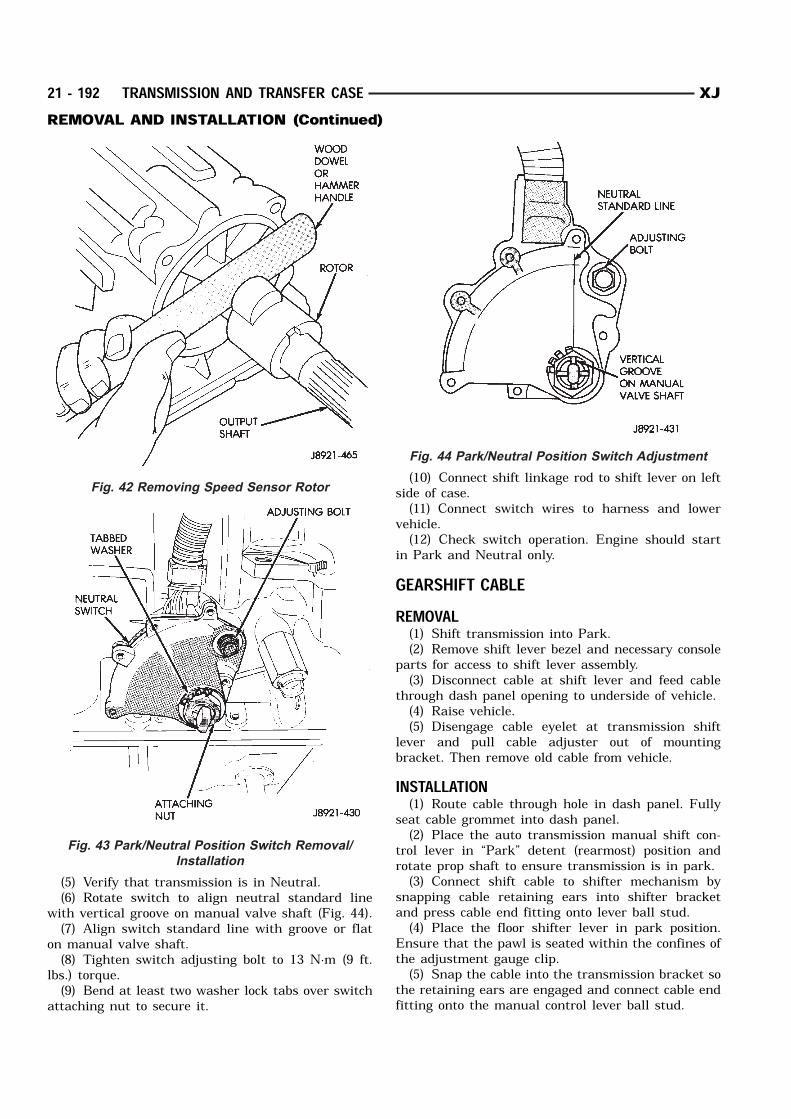
(5) Verify that transmission is in Neutral.(6) Rotate switch to align neutral standard line
with vertical groove on manual valve shaft (Fig. 44).(7) Align switch standard line with groove or flat
on manual valve shaft.(8) Tighten switch adjusting bolt to 13 N·m (9 ft.
lbs.) torque.(9) Bend at least two washer lock tabs over switch
attaching nut to secure it.
(10) Connect shift linkage rod to shift lever on leftside of case.(11) Connect switch wires to harness and lower
vehicle.(12) Check switch operation. Engine should start
in Park and Neutral only.GEARSHIFT CABLEREMOVAL(1) Shift transmission into Park.(2) Remove shift lever bezel and necessary console
parts for access to shift lever assembly.(3) Disconnect cable at shift lever and feed cable
through dash panel opening to underside of vehicle.(4) Raise vehicle.(5) Disengage cable eyelet at transmission shift
lever and pull cable adjuster out of mountingbracket. Then remove old cable from vehicle.INSTALLATION(1) Route cable through hole in dash panel. Fully
seat cable grommet into dash panel.(2) Place the auto transmission manual shift con-
trol lever in “Park” detent (rearmost) position androtate prop shaft to ensure transmission is in park.(3) Connect shift cable to shifter mechanism by
snapping cable retaining ears into shifter bracketand press cable end fitting onto lever ball stud.(4) Place the floor shifter lever in park position.
Ensure that the pawl is seated within the confines ofthe adjustment gauge clip.(5) Snap the cable into the transmission bracket so
the retaining ears are engaged and connect cable endfitting onto the manual control lever ball stud.
Fig. 42 Removing Speed Sensor Rotor
Fig. 43 Park/Neutral Position Switch Removal/
Installation
Fig. 44 Park/Neutral Position Switch Adjustment
21 - 192 TRANSMISSION AND TRANSFER CASE XJREMOVAL AND INSTALLATION (Continued)
(6) Lock shift cable into position by pushingupward on the adjusting lock button.(7) Remove and discard the shift cable adjustment
gauge clip from the park gate of the shifter.BRAKE TRANSMISSION SHIFT INTERLOCKREMOVAL(1) Remove lower steering column cover. Refer to
Group 8E, Instrument Panel and Gauges, for properprocedure.(2) Remove lower steering column shroud. Refer to
Group 19, Steering, for proper procedure.(3) Remove tie strap near the solenoid retaining
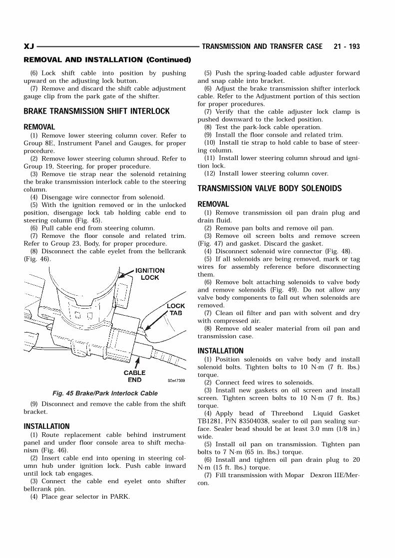
the brake transmission interlock cable to the steeringcolumn.(4) Disengage wire connector from solenoid.(5) With the ignition removed or in the unlocked
position, disengage lock tab holding cable end tosteering column (Fig. 45).(6) Pull cable end from steering column.(7) Remove the floor console and related trim.
Refer to Group 23, Body, for proper procedure.(8) Disconnect the cable eyelet from the bellcrank
(Fig. 46).
(9) Disconnect and remove the cable from the shiftbracket.INSTALLATION(1) Route replacement cable behind instrument
panel and under floor console area to shift mecha-nism (Fig. 46).(2) Insert cable end into opening in steering col-
umn hub under ignition lock. Push cable inwarduntil lock tab engages.(3) Connect the cable end eyelet onto shifter
bellcrank pin.(4) Place gear selector in PARK.
(5) Push the spring-loaded cable adjuster forwardand snap cable into bracket.(6) Adjust the brake transmission shifter interlock
cable. Refer to the Adjustment portion of this sectionfor proper procedures.(7) Verify that the cable adjuster lock clamp is
pushed downward to the locked position.(8) Test the park-lock cable operation.(9) Install the floor console and related trim.(10) Install tie strap to hold cable to base of steer-
ing column.(11) Install lower steering column shroud and igni-
tion lock.(12) Install lower steering column cover.
TRANSMISSION VALVE BODY SOLENOIDSREMOVAL(1) Remove transmission oil pan drain plug and
drain fluid.(2) Remove pan bolts and remove oil pan.(3) Remove oil screen bolts and remove screen
(Fig. 47) and gasket. Discard the gasket.(4) Disconnect solenoid wire connector (Fig. 48).(5) If all solenoids are being removed, mark or tag
wires for assembly reference before disconnectingthem.(6) Remove bolt attaching solenoids to valve body
and remove solenoids (Fig. 49). Do not allow anyvalve body components to fall out when solenoids areremoved.(7) Clean oil filter and pan with solvent and dry
with compressed air.(8) Remove old sealer material from oil pan and
transmission case.INSTALLATION(1) Position solenoids on valve body and install
solenoid bolts. Tighten bolts to 10 N·m (7 ft. lbs.)torque.(2) Connect feed wires to solenoids.(3) Install new gaskets on oil screen and install
screen. Tighten screen bolts to 10 N·m (7 ft. lbs.)torque.(4) Apply bead of Threebond Liquid Gasket
TB1281, P/N 83504038, sealer to oil pan sealing sur-face. Sealer bead should be at least 3.0 mm (1/8 in.)wide.(5) Install oil pan on transmission. Tighten pan
bolts to 7 N·m (65 in. lbs.) torque.(6) Install and tighten oil pan drain plug to 20
N·m (15 ft. lbs.) torque.(7) Fill transmission with Mopar Dexron IIE/Mer-
con.
Fig. 45 Brake/Park Interlock Cable
XJ TRANSMISSION AND TRANSFER CASE 21 - 193REMOVAL AND INSTALLATION (Continued)
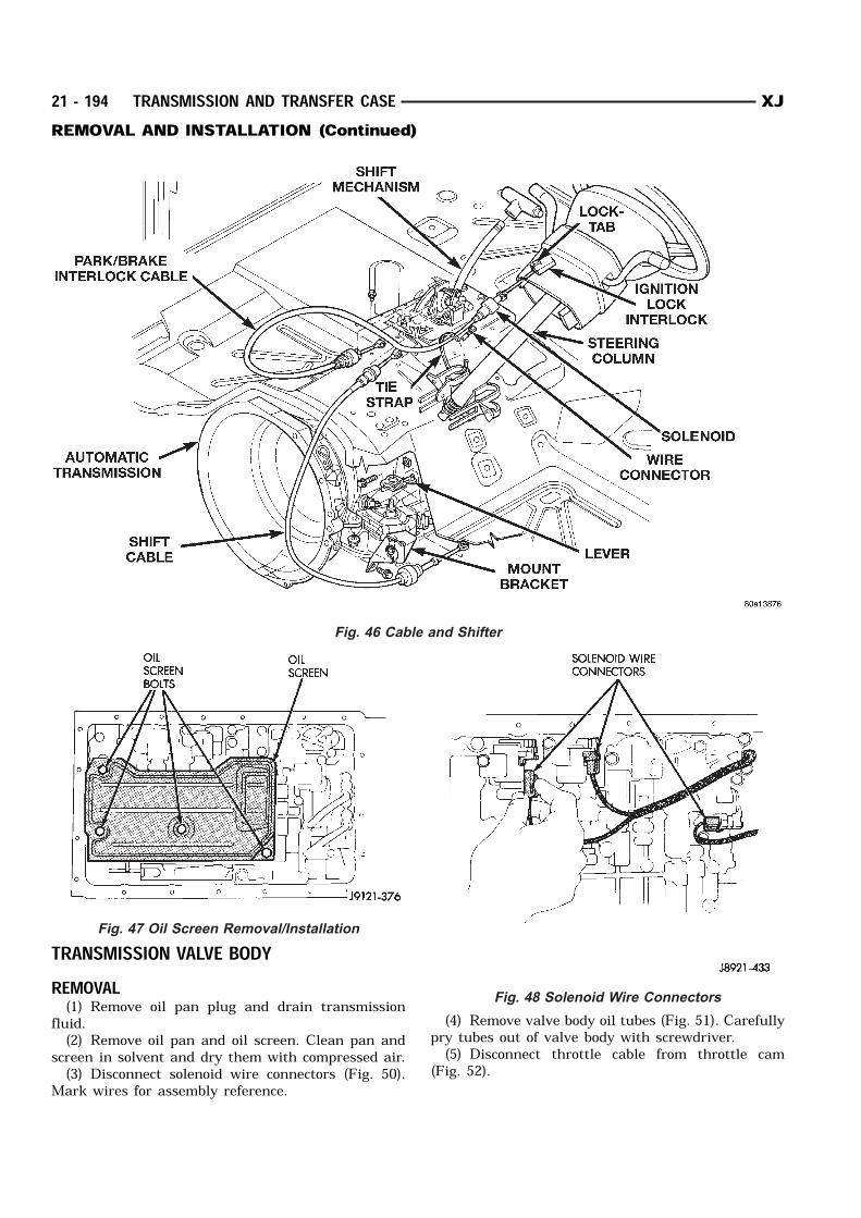
TRANSMISSION VALVE BODYREMOVAL(1) Remove oil pan plug and drain transmission
fluid.(2) Remove oil pan and oil screen. Clean pan and
screen in solvent and dry them with compressed air.(3) Disconnect solenoid wire connectors (Fig. 50).
Mark wires for assembly reference.
(4) Remove valve body oil tubes (Fig. 51). Carefullypry tubes out of valve body with screwdriver.(5) Disconnect throttle cable from throttle cam
(Fig. 52).
Fig. 46 Cable and Shifter
Fig. 47 Oil Screen Removal/Installation
Fig. 48 Solenoid Wire Connectors
21 - 194 TRANSMISSION AND TRANSFER CASE XJREMOVAL AND INSTALLATION (Continued)
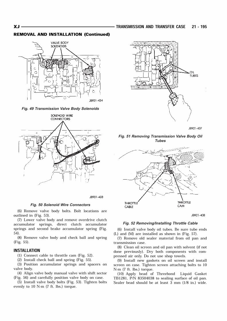
(6) Remove valve body bolts. Bolt locations areoutlined in (Fig. 53).(7) Lower valve body and remove overdrive clutch
accumulator springs, direct clutch accumulatorsprings and second brake accumulator spring (Fig.54).(8) Remove valve body and check ball and spring
(Fig. 55).INSTALLATION(1) Connect cable to throttle cam (Fig. 52).(2) Install check ball and spring (Fig. 55).(3) Position accumulator springs and spacers on
valve body.(4) Align valve body manual valve with shift sector
(Fig. 56) and carefully position valve body on case.(5) Install valve body bolts (Fig. 53). Tighten bolts
evenly to 10 N·m (7 ft. lbs.) torque.
(6) Install valve body oil tubes. Be sure tube ends(L) and (M) are installed as shown in (Fig. 57).(7) Remove old sealer material from oil pan and
transmission case.(8) Clean oil screen and oil pan with solvent (if not
done previously). Dry both components with com-pressed air only. Do not use shop towels.(9) Install new gaskets on oil screen and install
screen on case. Tighten screen attaching bolts to 10N·m (7 ft. lbs.) torque.(10) Apply bead of Threebond Liquid Gasket
TB1281, P/N 83504038 to sealing surface of oil pan.Sealer bead should be at least 3 mm (1/8 in.) wide.
Fig. 49 Transmission Valve Body Solenoids
Fig. 50 Solenoid Wire Connectors
Fig. 51 Removing Transmission Valve Body Oil
Tubes
Fig. 52 Removing/Installing Throttle Cable
XJ TRANSMISSION AND TRANSFER CASE 21 - 195REMOVAL AND INSTALLATION (Continued)
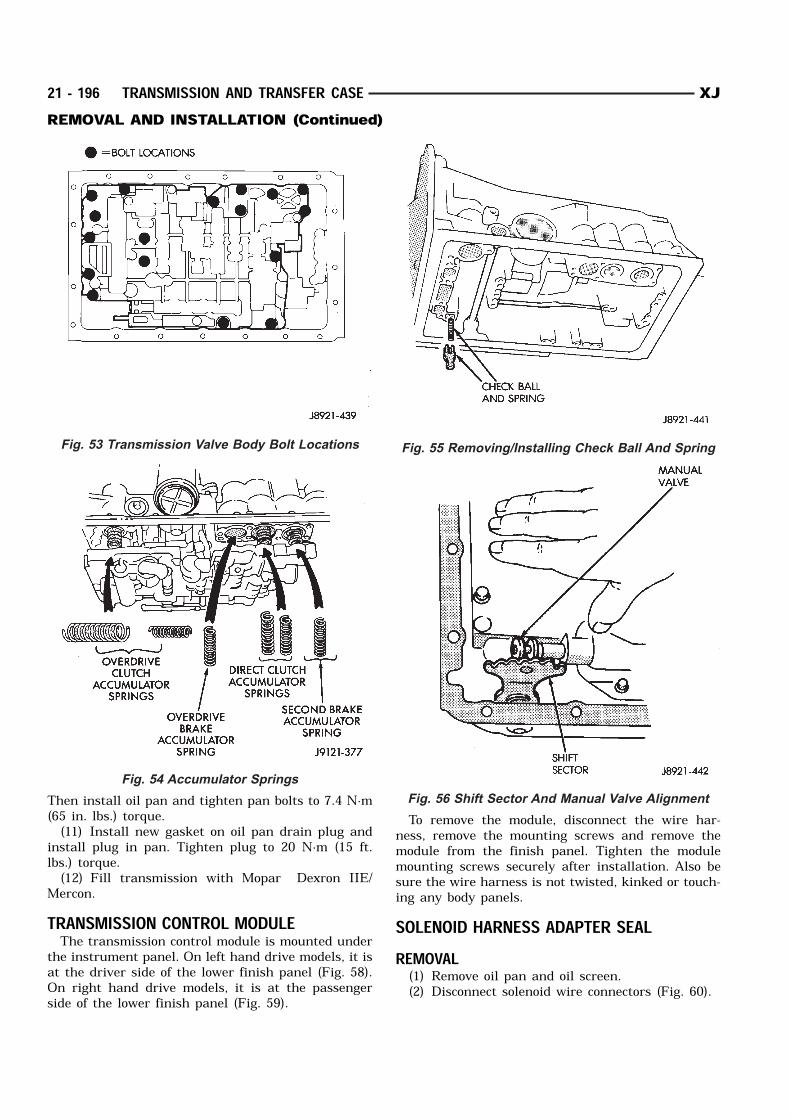
Then install oil pan and tighten pan bolts to 7.4 N·m(65 in. lbs.) torque.(11) Install new gasket on oil pan drain plug and
install plug in pan. Tighten plug to 20 N·m (15 ft.lbs.) torque.(12) Fill transmission with Mopar Dexron IIE/
Mercon.TRANSMISSION CONTROL MODULEThe transmission control module is mounted under
the instrument panel. On left hand drive models, it isat the driver side of the lower finish panel (Fig. 58).On right hand drive models, it is at the passengerside of the lower finish panel (Fig. 59).
To remove the module, disconnect the wire har-ness, remove the mounting screws and remove themodule from the finish panel. Tighten the modulemounting screws securely after installation. Also besure the wire harness is not twisted, kinked or touch-ing any body panels.SOLENOID HARNESS ADAPTER SEALREMOVAL(1) Remove oil pan and oil screen.(2) Disconnect solenoid wire connectors (Fig. 60).
Fig. 53 Transmission Valve Body Bolt Locations
Fig. 54 Accumulator Springs
Fig. 55 Removing/Installing Check Ball And Spring
Fig. 56 Shift Sector And Manual Valve Alignment
21 - 196 TRANSMISSION AND TRANSFER CASE XJREMOVAL AND INSTALLATION (Continued)

(3) Remove bracket securing solenoid harnessadaptor (Fig. 61) to case.(4) Pull harness adapter and wires out of case.(5) Remove and discard adapter O–ring.
INSTALLATION(1) Lubricate new O–ring and install it on adapter.(2) Install solenoid wire harness and adapter in
case.(3) Install adapter bracket and bracket bolt.
(4) Connect wires to solenoids.(5) Install oil screen.(6) Apply bead of Threebond Liquid Gasket
TB1281, P/N 83504038, to oil pan seal surface.Sealer bead should be at least 3 mm (1/8 in.) wide.(7) Install oil pan on transmission. Tighten pan
bolts to 7 N·m (65 in. lbs.) torque.(8) Install and tighten oil pan drain plug to 20
N·m (15 ft. lbs.) torque.(9) Fill transmission with Mopar Dexron IIE/Mer-
con.
Fig. 57 Installing Transmission Valve Body Oil
Tubes
Fig. 58 TCM Location (Left Hand Drive)
Fig. 59 TCM Location (Right Hand Drive)
Fig. 60 Solenoid Wire Connectors
Fig. 61 Harness Adapter Removal/Installation
XJ TRANSMISSION AND TRANSFER CASE 21 - 197REMOVAL AND INSTALLATION (Continued)
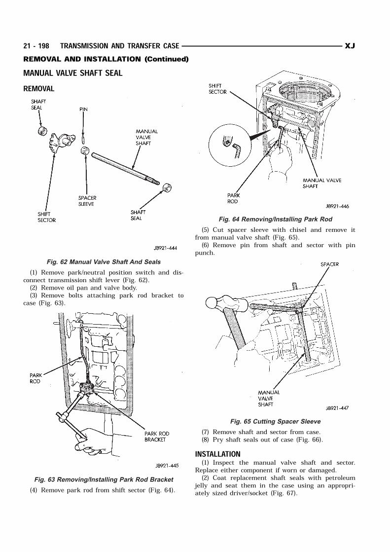
MANUAL VALVE SHAFT SEALREMOVAL
(1) Remove park/neutral position switch and dis-connect transmission shift lever (Fig. 62).(2) Remove oil pan and valve body.(3) Remove bolts attaching park rod bracket to
case (Fig. 63).
(4) Remove park rod from shift sector (Fig. 64).
(5) Cut spacer sleeve with chisel and remove itfrom manual valve shaft (Fig. 65).(6) Remove pin from shaft and sector with pin
punch.
(7) Remove shaft and sector from case.(8) Pry shaft seals out of case (Fig. 66).
INSTALLATION(1) Inspect the manual valve shaft and sector.
Replace either component if worn or damaged.(2) Coat replacement shaft seals with petroleum
jelly and seat them in the case using an appropri-ately sized driver/socket (Fig. 67).
Fig. 62 Manual Valve Shaft And Seals
Fig. 63 Removing/Installing Park Rod Bracket
Fig. 64 Removing/Installing Park Rod
Fig. 65 Cutting Spacer Sleeve
21 - 198 TRANSMISSION AND TRANSFER CASE XJREMOVAL AND INSTALLATION (Continued)
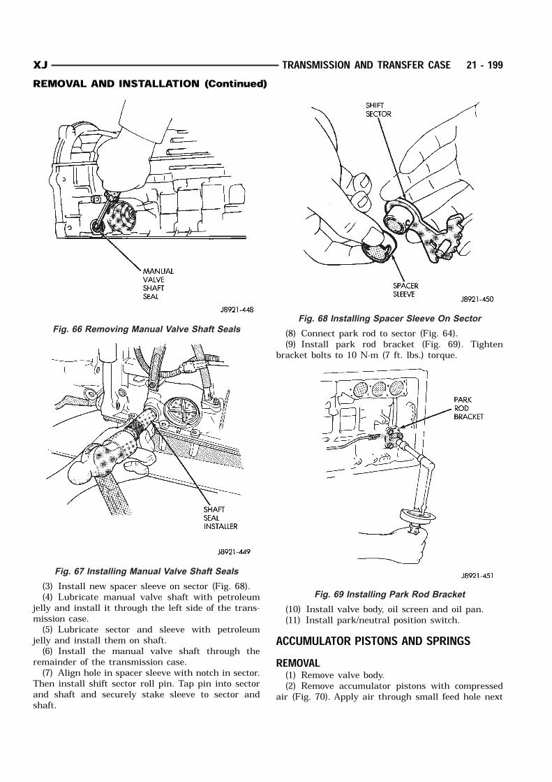
(3) Install new spacer sleeve on sector (Fig. 68).(4) Lubricate manual valve shaft with petroleum
jelly and install it through the left side of the trans-mission case.(5) Lubricate sector and sleeve with petroleum
jelly and install them on shaft.(6) Install the manual valve shaft through the
remainder of the transmission case.(7) Align hole in spacer sleeve with notch in sector.
Then install shift sector roll pin. Tap pin into sectorand shaft and securely stake sleeve to sector andshaft.
(8) Connect park rod to sector (Fig. 64).(9) Install park rod bracket (Fig. 69). Tighten
bracket bolts to 10 N·m (7 ft. lbs.) torque.
(10) Install valve body, oil screen and oil pan.(11) Install park/neutral position switch.
ACCUMULATOR PISTONS AND SPRINGSREMOVAL(1) Remove valve body.(2) Remove accumulator pistons with compressed
air (Fig. 70). Apply air through small feed hole next
Fig. 66 Removing Manual Valve Shaft Seals
Fig. 67 Installing Manual Valve Shaft Seals
Fig. 68 Installing Spacer Sleeve On Sector
Fig. 69 Installing Park Rod Bracket
XJ TRANSMISSION AND TRANSFER CASE 21 - 199REMOVAL AND INSTALLATION (Continued)
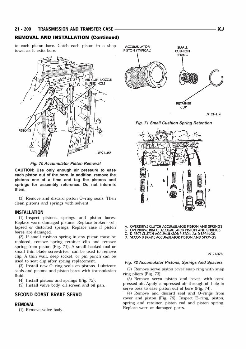
to each piston bore. Catch each piston in a shoptowel as it exits bore.
CAUTION: Use only enough air pressure to ease
each piston out of the bore. In addition, remove the
pistons one at a time and tag the pistons and
springs for assembly reference. Do not intermix
them.
(3) Remove and discard piston O–ring seals. Thenclean pistons and springs with solvent.INSTALLATION(1) Inspect pistons, springs and piston bores.
Replace worn damaged pistons. Replace broken, col-lapsed or distorted springs. Replace case if pistonbores are damaged.(2) If small cushion spring in any piston must be
replaced, remove spring retainer clip and removespring from piston (Fig. 71). A small hooked tool orsmall thin blade screwdriver can be used to removeclip. A thin wall, deep socket, or pin punch can beused to seat clip after spring replacement.(3) Install new O–ring seals on pistons. Lubricate
seals and pistons and piston bores with transmissionfluid.(4) Install pistons and springs (Fig. 72).(5) Install valve body, oil screen and oil pan.
SECOND COAST BRAKE SERVOREMOVAL(1) Remove valve body.
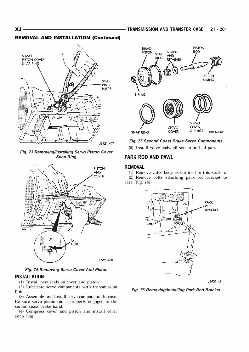
(2) Remove servo piston cover snap ring with snapring pliers (Fig. 73).(3) Remove servo piston and cover with com-
pressed air. Apply compressed air through oil hole inservo boss to ease piston out of bore (Fig. 74).(4) Remove and discard seal and O–rings from
cover and piston (Fig. 75). Inspect E–ring, piston,spring and retainer, piston rod and piston spring.Replace worn or damaged parts.
Fig. 70 Accumulator Piston Removal
Fig. 71 Small Cushion Spring Retention
Fig. 72 Accumulator Pistons, Springs And Spacers
21 - 200 TRANSMISSION AND TRANSFER CASE XJREMOVAL AND INSTALLATION (Continued)
INSTALLATION(1) Install new seals on cover and piston.(2) Lubricate servo components with transmission
fluid.(3) Assemble and install servo components in case.
Be sure servo piston rod is properly engaged in thesecond coast brake band.(4) Compress cover and piston and install cover
snap ring.
(5) Install valve body, oil screen and oil pan.PARK ROD AND PAWLREMOVAL(1) Remove valve body as outlined in this section.(2) Remove bolts attaching park rod bracket to
case (Fig. 76).
Fig. 73 Removing/Installing Servo Piston Cover
Snap Ring
Fig. 74 Removing Servo Cover And Piston
Fig. 75 Second Coast Brake Servo Components
Fig. 76 Removing/Installing Park Rod Bracket
XJ TRANSMISSION AND TRANSFER CASE 21 - 201REMOVAL AND INSTALLATION (Continued)
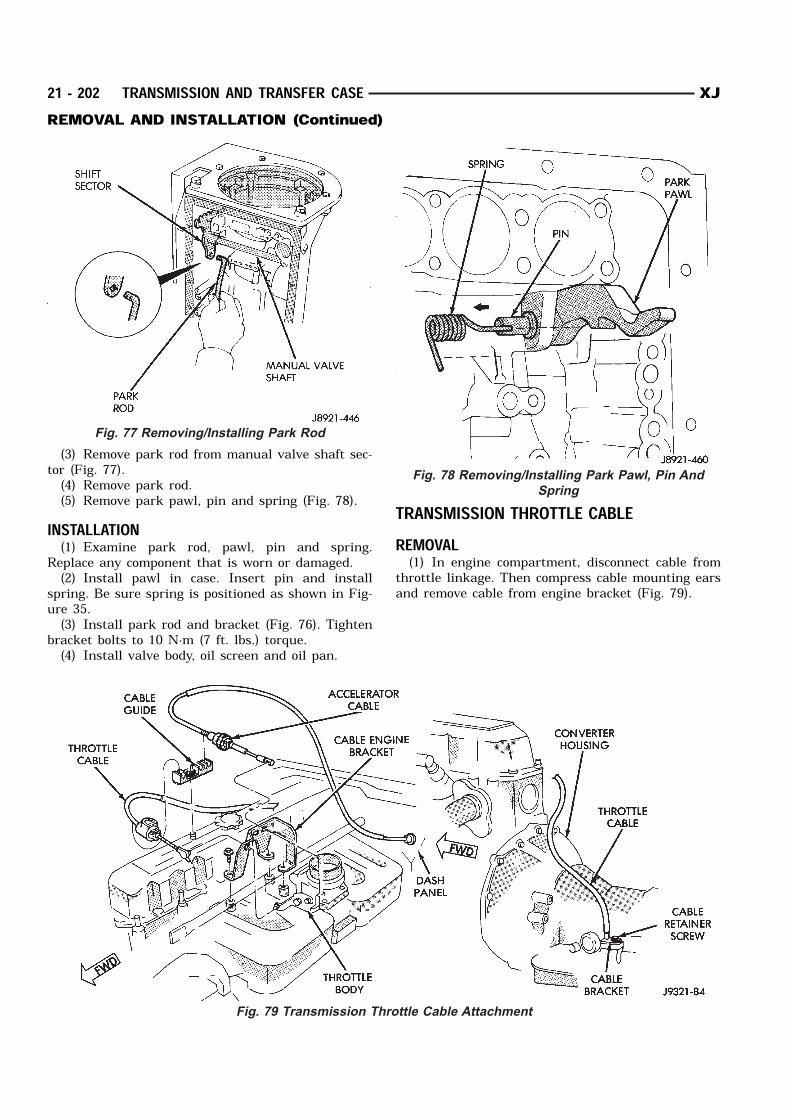
(3) Remove park rod from manual valve shaft sec-tor (Fig. 77).(4) Remove park rod.(5) Remove park pawl, pin and spring (Fig. 78).
INSTALLATION(1) Examine park rod, pawl, pin and spring.
Replace any component that is worn or damaged.(2) Install pawl in case. Insert pin and install
spring. Be sure spring is positioned as shown in Fig-ure 35.(3) Install park rod and bracket (Fig. 76). Tighten
bracket bolts to 10 N·m (7 ft. lbs.) torque.(4) Install valve body, oil screen and oil pan.
TRANSMISSION THROTTLE CABLEREMOVAL(1) In engine compartment, disconnect cable from
throttle linkage. Then compress cable mounting earsand remove cable from engine bracket (Fig. 79).
Fig. 78 Removing/Installing Park Pawl, Pin And
Spring
Fig. 77 Removing/Installing Park Rod
Fig. 79 Transmission Throttle Cable Attachment
21 - 202 TRANSMISSION AND TRANSFER CASE XJREMOVAL AND INSTALLATION (Continued)
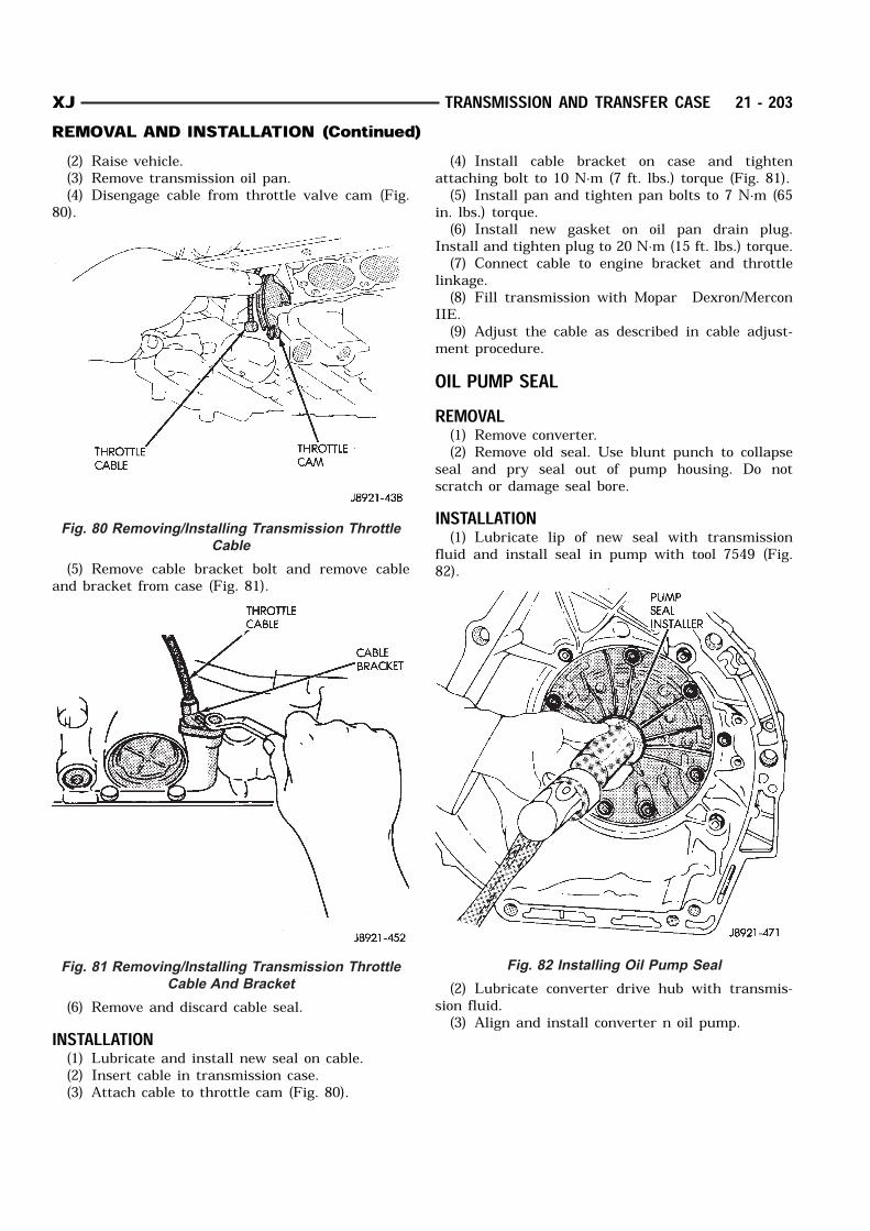
(2) Raise vehicle.(3) Remove transmission oil pan.(4) Disengage cable from throttle valve cam (Fig.
80).
(5) Remove cable bracket bolt and remove cableand bracket from case (Fig. 81).
(6) Remove and discard cable seal.INSTALLATION(1) Lubricate and install new seal on cable.(2) Insert cable in transmission case.(3) Attach cable to throttle cam (Fig. 80).
(4) Install cable bracket on case and tightenattaching bolt to 10 N·m (7 ft. lbs.) torque (Fig. 81).(5) Install pan and tighten pan bolts to 7 N·m (65
in. lbs.) torque.(6) Install new gasket on oil pan drain plug.
Install and tighten plug to 20 N·m (15 ft. lbs.) torque.(7) Connect cable to engine bracket and throttle
linkage.(8) Fill transmission with Mopar Dexron/Mercon
IIE.(9) Adjust the cable as described in cable adjust-
ment procedure.OIL PUMP SEALREMOVAL(1) Remove converter.(2) Remove old seal. Use blunt punch to collapse
seal and pry seal out of pump housing. Do notscratch or damage seal bore.INSTALLATION(1) Lubricate lip of new seal with transmission
fluid and install seal in pump with tool 7549 (Fig.82).
(2) Lubricate converter drive hub with transmis-sion fluid.(3) Align and install converter n oil pump.
Fig. 80 Removing/Installing Transmission Throttle
Cable
Fig. 81 Removing/Installing Transmission Throttle
Cable And Bracket
Fig. 82 Installing Oil Pump Seal
XJ TRANSMISSION AND TRANSFER CASE 21 - 203REMOVAL AND INSTALLATION (Continued)
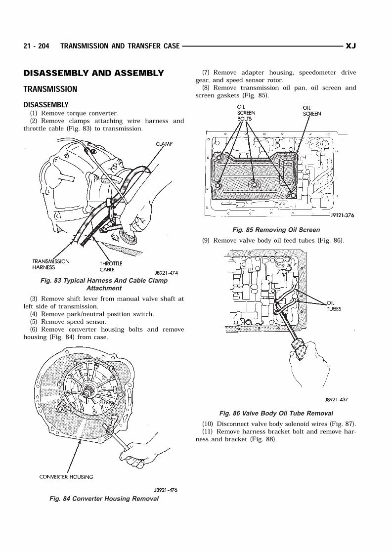
DISASSEMBLY AND ASSEMBLYTRANSMISSIONDISASSEMBLY(1) Remove torque converter.(2) Remove clamps attaching wire harness and
throttle cable (Fig. 83) to transmission.
(3) Remove shift lever from manual valve shaft atleft side of transmission.(4) Remove park/neutral position switch.(5) Remove speed sensor.(6) Remove converter housing bolts and remove
housing (Fig. 84) from case.
(7) Remove adapter housing, speedometer drivegear, and speed sensor rotor.(8) Remove transmission oil pan, oil screen and
screen gaskets (Fig. 85).
(9) Remove valve body oil feed tubes (Fig. 86).
(10) Disconnect valve body solenoid wires (Fig. 87).(11) Remove harness bracket bolt and remove har-
ness and bracket (Fig. 88).
Fig. 83 Typical Harness And Cable Clamp
Attachment
Fig. 84 Converter Housing Removal
Fig. 85 Removing Oil Screen
Fig. 86 Valve Body Oil Tube Removal
21 - 204 TRANSMISSION AND TRANSFER CASE XJ
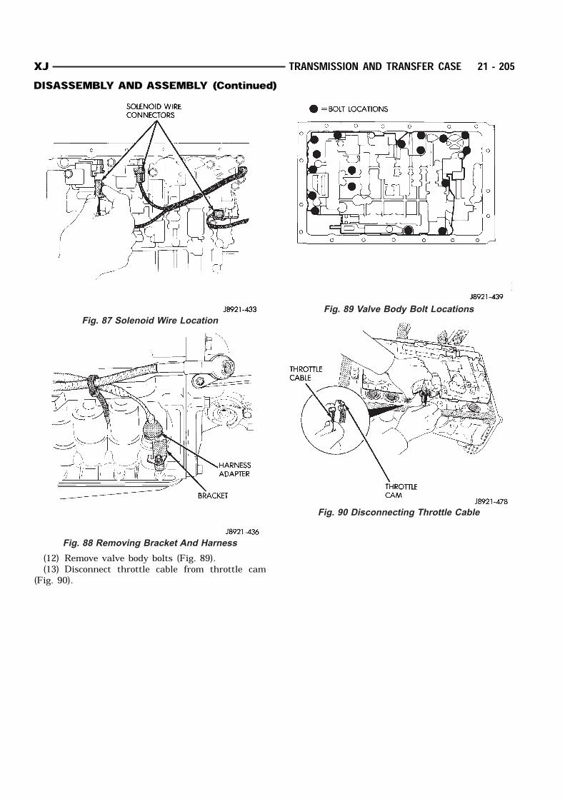
(12) Remove valve body bolts (Fig. 89).(13) Disconnect throttle cable from throttle cam
(Fig. 90).
Fig. 87 Solenoid Wire Location
Fig. 88 Removing Bracket And Harness
Fig. 89 Valve Body Bolt Locations
Fig. 90 Disconnecting Throttle Cable
XJ TRANSMISSION AND TRANSFER CASE 21 - 205DISASSEMBLY AND ASSEMBLY (Continued)
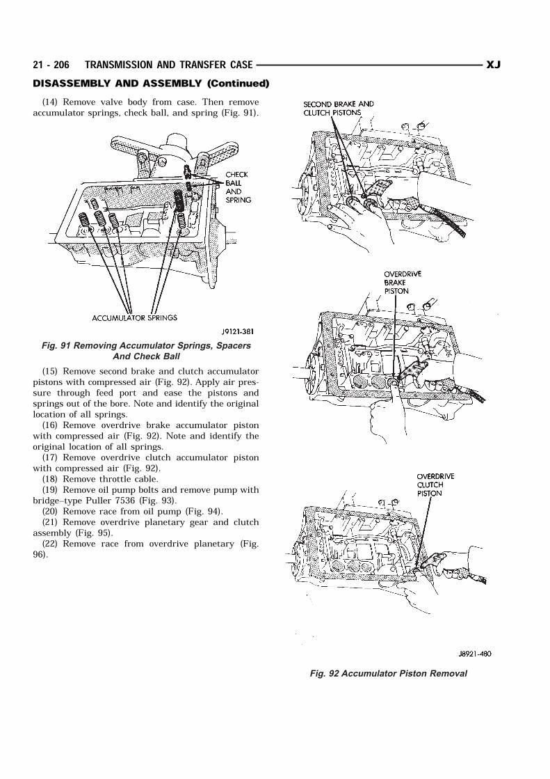
(14) Remove valve body from case. Then removeaccumulator springs, check ball, and spring (Fig. 91).
(15) Remove second brake and clutch accumulatorpistons with compressed air (Fig. 92). Apply air pres-sure through feed port and ease the pistons andsprings out of the bore. Note and identify the originallocation of all springs.(16) Remove overdrive brake accumulator piston
with compressed air (Fig. 92). Note and identify theoriginal location of all springs.(17) Remove overdrive clutch accumulator piston
with compressed air (Fig. 92).(18) Remove throttle cable.(19) Remove oil pump bolts and remove pump with
bridge–type Puller 7536 (Fig. 93).(20) Remove race from oil pump (Fig. 94).(21) Remove overdrive planetary gear and clutch
assembly (Fig. 95).(22) Remove race from overdrive planetary (Fig.
96).
Fig. 91 Removing Accumulator Springs, Spacers
And Check Ball
Fig. 92 Accumulator Piston Removal
21 - 206 TRANSMISSION AND TRANSFER CASE XJDISASSEMBLY AND ASSEMBLY (Continued)
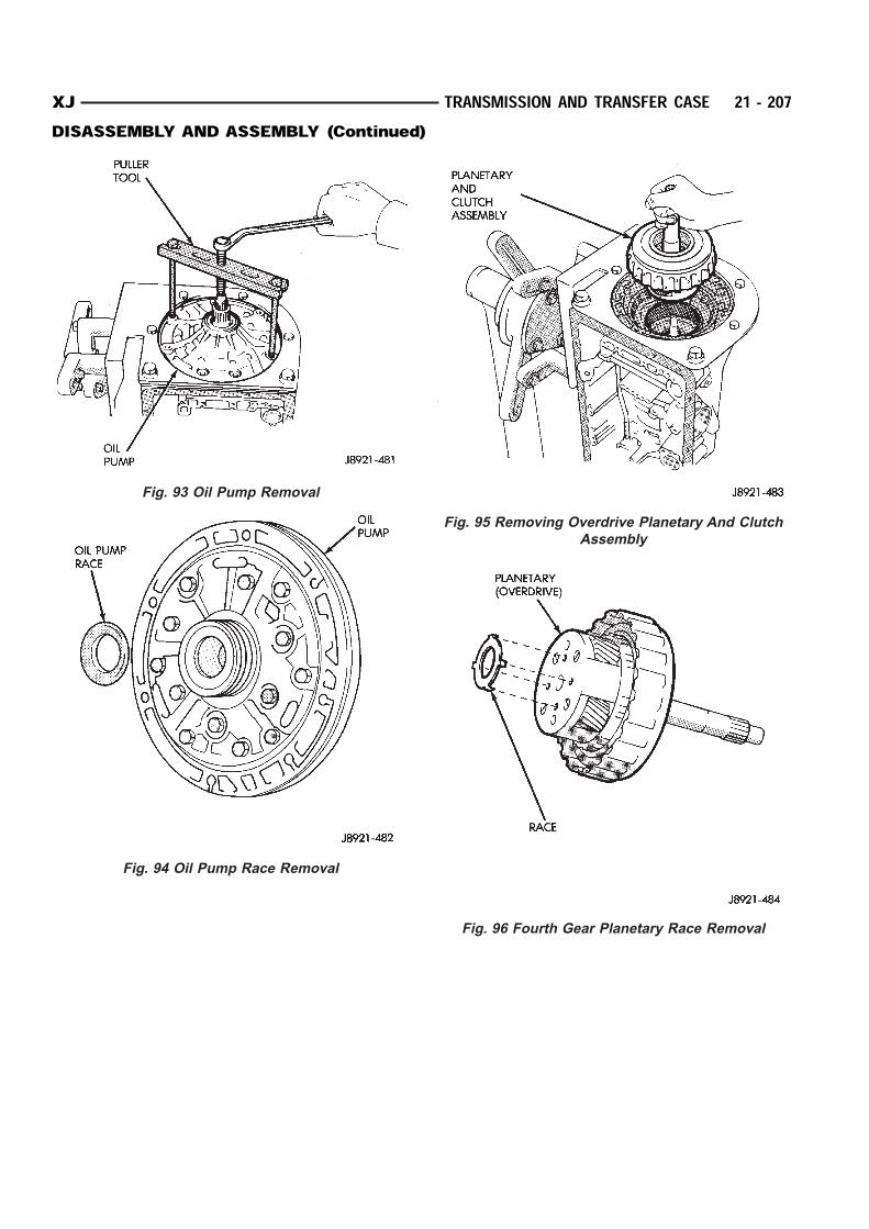
Fig. 93 Oil Pump Removal
Fig. 94 Oil Pump Race Removal
Fig. 95 Removing Overdrive Planetary And Clutch
Assembly
Fig. 96 Fourth Gear Planetary Race Removal
XJ TRANSMISSION AND TRANSFER CASE 21 - 207DISASSEMBLY AND ASSEMBLY (Continued)
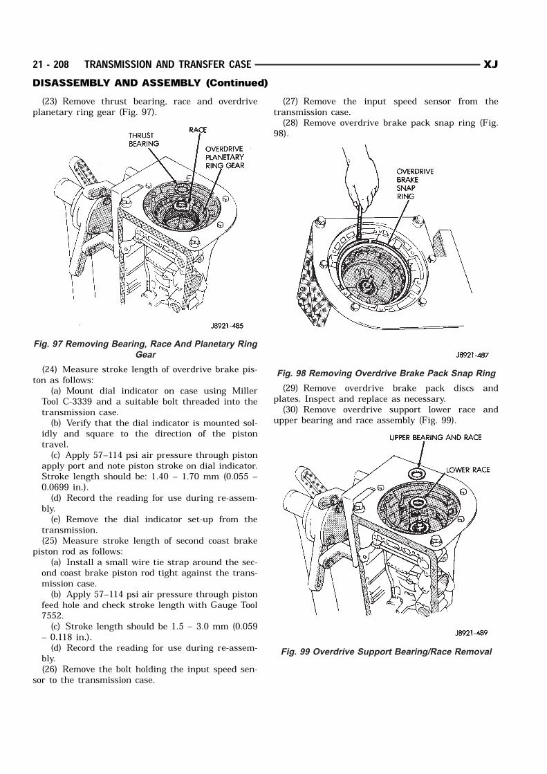
(23) Remove thrust bearing, race and overdriveplanetary ring gear (Fig. 97).
(24) Measure stroke length of overdrive brake pis-ton as follows:
(a) Mount dial indicator on case using MillerTool C-3339 and a suitable bolt threaded into thetransmission case.(b) Verify that the dial indicator is mounted sol-
idly and square to the direction of the pistontravel.(c) Apply 57–114 psi air pressure through piston
apply port and note piston stroke on dial indicator.Stroke length should be: 1.40 – 1.70 mm (0.055 –0.0699 in.).(d) Record the reading for use during re-assem-
bly.(e) Remove the dial indicator set-up from the
transmission.(25) Measure stroke length of second coast brake
piston rod as follows:(a) Install a small wire tie strap around the sec-
ond coast brake piston rod tight against the trans-mission case.(b) Apply 57–114 psi air pressure through piston
feed hole and check stroke length with Gauge Tool7552.(c) Stroke length should be 1.5 – 3.0 mm (0.059
– 0.118 in.).(d) Record the reading for use during re-assem-
bly.(26) Remove the bolt holding the input speed sen-
sor to the transmission case.
(27) Remove the input speed sensor from thetransmission case.(28) Remove overdrive brake pack snap ring (Fig.
98).
(29) Remove overdrive brake pack discs andplates. Inspect and replace as necessary.(30) Remove overdrive support lower race and
upper bearing and race assembly (Fig. 99).
Fig. 97 Removing Bearing, Race And Planetary Ring
Gear
Fig. 98 Removing Overdrive Brake Pack Snap Ring
Fig. 99 Overdrive Support Bearing/Race Removal
21 - 208 TRANSMISSION AND TRANSFER CASE XJDISASSEMBLY AND ASSEMBLY (Continued)
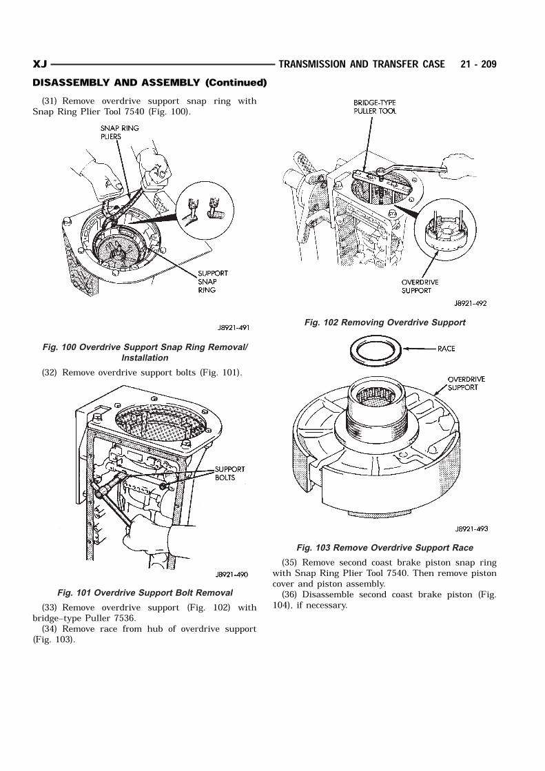
(31) Remove overdrive support snap ring withSnap Ring Plier Tool 7540 (Fig. 100).
(32) Remove overdrive support bolts (Fig. 101).
(33) Remove overdrive support (Fig. 102) withbridge–type Puller 7536.(34) Remove race from hub of overdrive support
(Fig. 103).
(35) Remove second coast brake piston snap ringwith Snap Ring Plier Tool 7540. Then remove pistoncover and piston assembly.(36) Disassemble second coast brake piston (Fig.
104), if necessary.
Fig. 100 Overdrive Support Snap Ring Removal/
Installation
Fig. 101 Overdrive Support Bolt Removal
Fig. 102 Removing Overdrive Support
Fig. 103 Remove Overdrive Support Race
XJ TRANSMISSION AND TRANSFER CASE 21 - 209DISASSEMBLY AND ASSEMBLY (Continued)
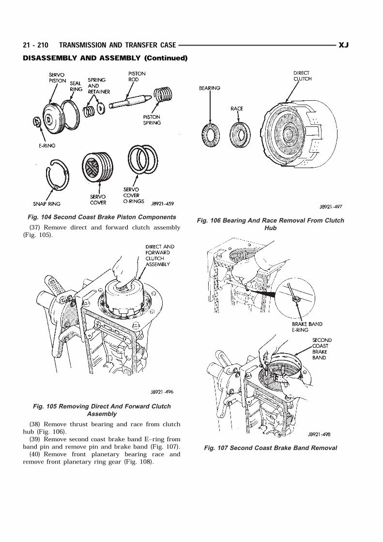
(37) Remove direct and forward clutch assembly(Fig. 105).
(38) Remove thrust bearing and race from clutchhub (Fig. 106).(39) Remove second coast brake band E–ring from
band pin and remove pin and brake band (Fig. 107).(40) Remove front planetary bearing race and
remove front planetary ring gear (Fig. 108).
Fig. 104 Second Coast Brake Piston Components
Fig. 105 Removing Direct And Forward Clutch
Assembly
Fig. 106 Bearing And Race Removal From Clutch
Hub
Fig. 107 Second Coast Brake Band Removal
21 - 210 TRANSMISSION AND TRANSFER CASE XJDISASSEMBLY AND ASSEMBLY (Continued)
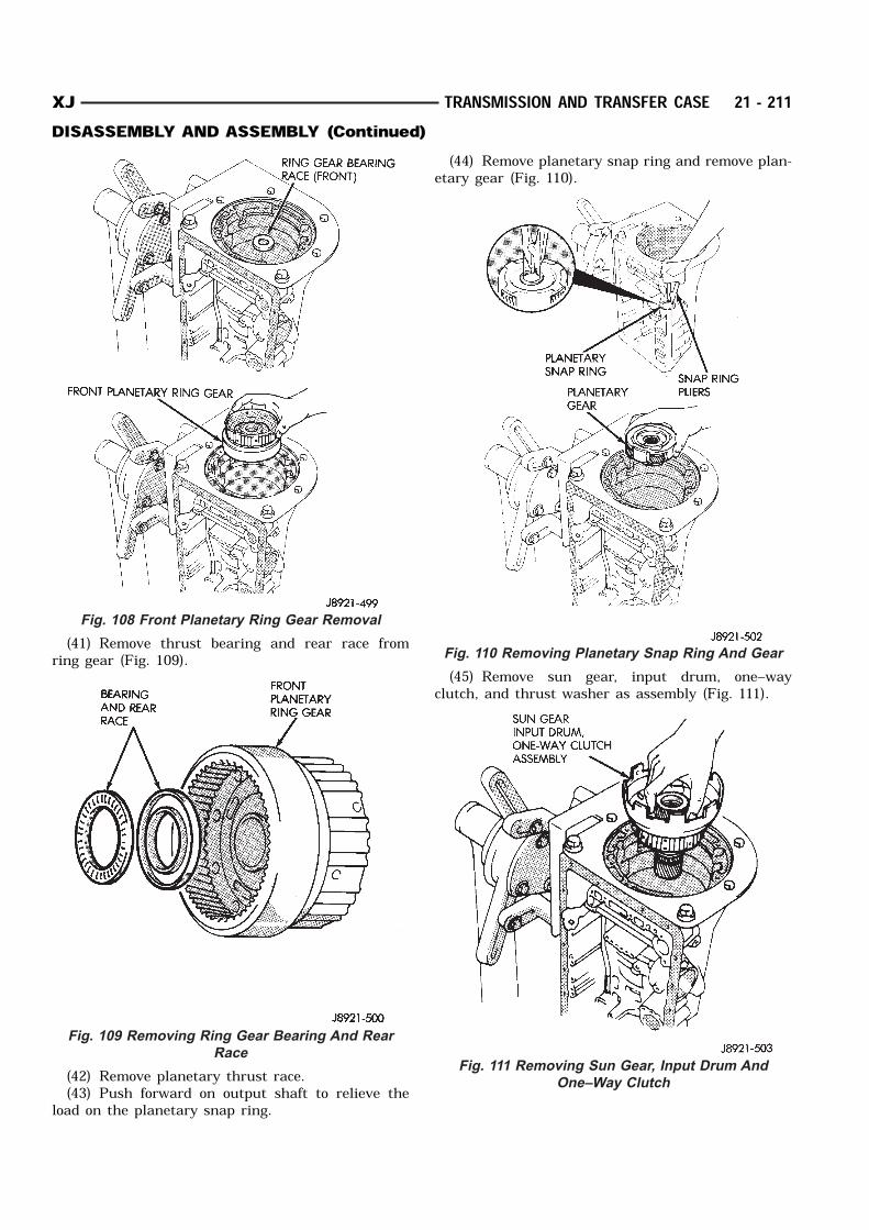
(41) Remove thrust bearing and rear race fromring gear (Fig. 109).
(42) Remove planetary thrust race.(43) Push forward on output shaft to relieve the
load on the planetary snap ring.
(44) Remove planetary snap ring and remove plan-etary gear (Fig. 110).
(45) Remove sun gear, input drum, one–wayclutch, and thrust washer as assembly (Fig. 111).
Fig. 108 Front Planetary Ring Gear Removal
Fig. 109 Removing Ring Gear Bearing And Rear
Race
Fig. 110 Removing Planetary Snap Ring And Gear
Fig. 111 Removing Sun Gear, Input Drum And
One–Way Clutch
XJ TRANSMISSION AND TRANSFER CASE 21 - 211DISASSEMBLY AND ASSEMBLY (Continued)
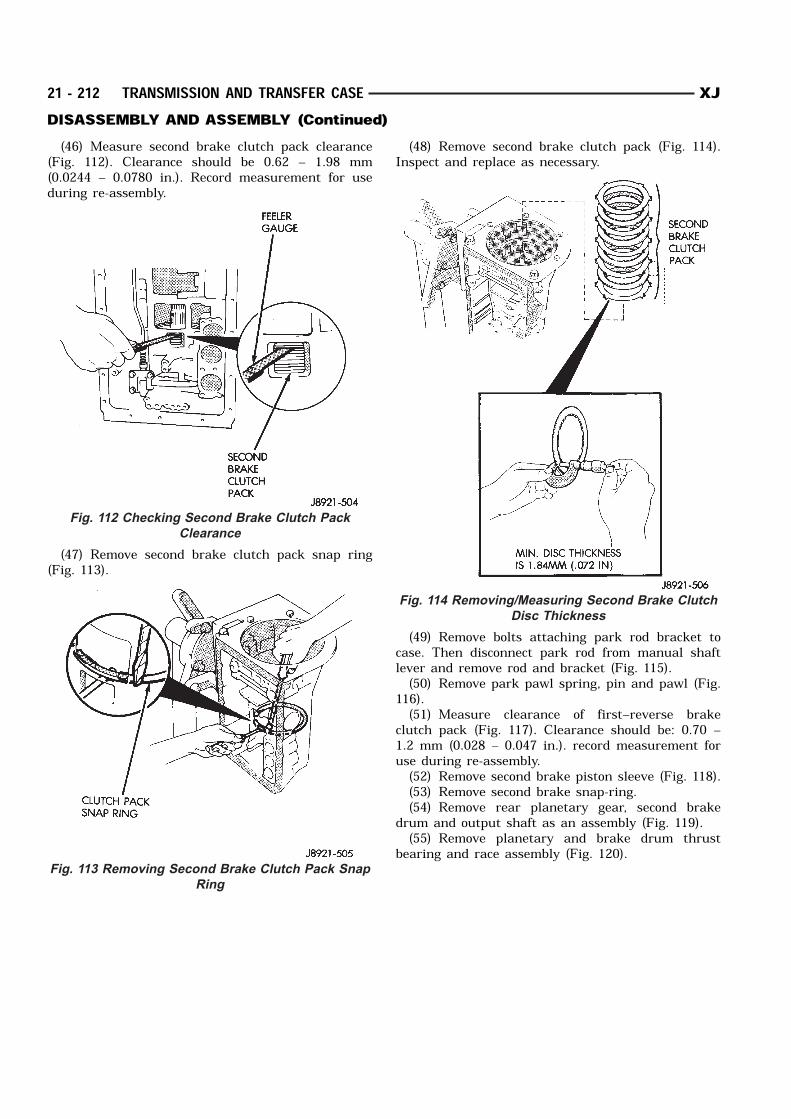
(46) Measure second brake clutch pack clearance(Fig. 112). Clearance should be 0.62 – 1.98 mm(0.0244 – 0.0780 in.). Record measurement for useduring re-assembly.
(47) Remove second brake clutch pack snap ring(Fig. 113).
(48) Remove second brake clutch pack (Fig. 114).Inspect and replace as necessary.
(49) Remove bolts attaching park rod bracket tocase. Then disconnect park rod from manual shaftlever and remove rod and bracket (Fig. 115).(50) Remove park pawl spring, pin and pawl (Fig.
116).(51) Measure clearance of first–reverse brake
clutch pack (Fig. 117). Clearance should be: 0.70 –1.2 mm (0.028 – 0.047 in.). record measurement foruse during re-assembly.(52) Remove second brake piston sleeve (Fig. 118).(53) Remove second brake snap-ring.(54) Remove rear planetary gear, second brake
drum and output shaft as an assembly (Fig. 119).(55) Remove planetary and brake drum thrust
bearing and race assembly (Fig. 120).
Fig. 112 Checking Second Brake Clutch Pack
Clearance
Fig. 113 Removing Second Brake Clutch Pack Snap
Ring
Fig. 114 Removing/Measuring Second Brake Clutch
Disc Thickness
21 - 212 TRANSMISSION AND TRANSFER CASE XJDISASSEMBLY AND ASSEMBLY (Continued)
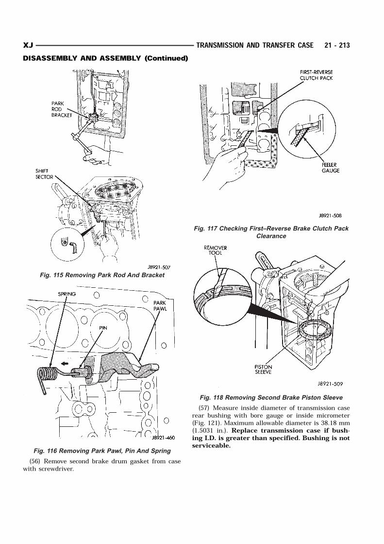
(56) Remove second brake drum gasket from casewith screwdriver.
(57) Measure inside diameter of transmission caserear bushing with bore gauge or inside micrometer(Fig. 121). Maximum allowable diameter is 38.18 mm(1.5031 in.). Replace transmission case if bush-ing I.D. is greater than specified. Bushing is notserviceable.
Fig. 115 Removing Park Rod And Bracket
Fig. 116 Removing Park Pawl, Pin And Spring
Fig. 117 Checking First–Reverse Brake Clutch Pack
Clearance
Fig. 118 Removing Second Brake Piston Sleeve
XJ TRANSMISSION AND TRANSFER CASE 21 - 213DISASSEMBLY AND ASSEMBLY (Continued)
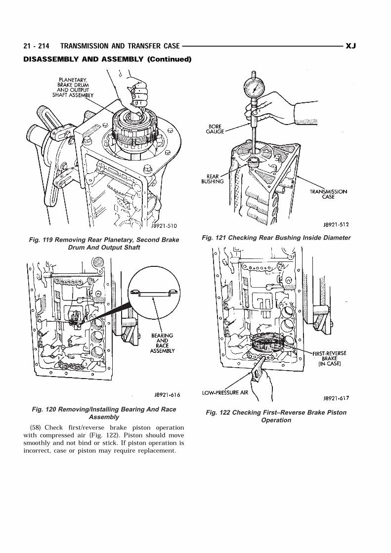
(58) Check first/reverse brake piston operationwith compressed air (Fig. 122). Piston should movesmoothly and not bind or stick. If piston operation isincorrect, case or piston may require replacement.
Fig. 119 Removing Rear Planetary, Second Brake
Drum And Output Shaft
Fig. 120 Removing/Installing Bearing And Race
Assembly
Fig. 121 Checking Rear Bushing Inside Diameter
Fig. 122 Checking First–Reverse Brake Piston
Operation
21 - 214 TRANSMISSION AND TRANSFER CASE XJDISASSEMBLY AND ASSEMBLY (Continued)
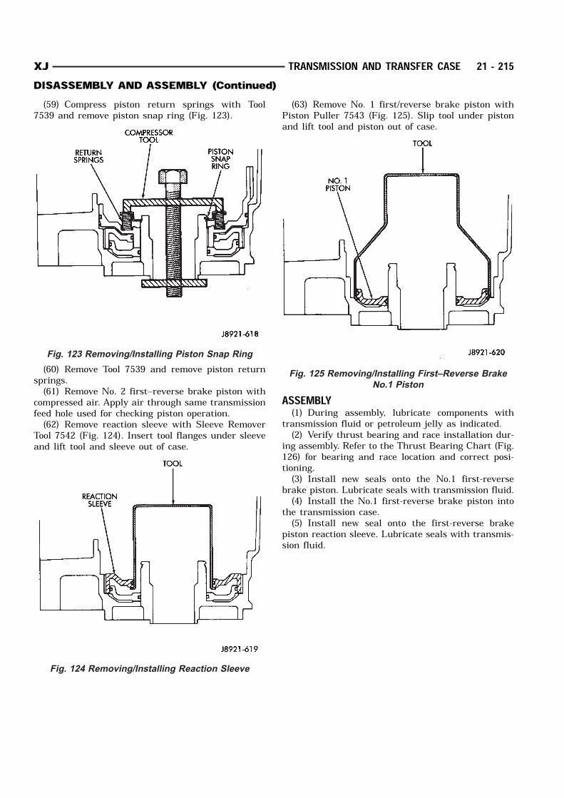
(59) Compress piston return springs with Tool7539 and remove piston snap ring (Fig. 123).
(60) Remove Tool 7539 and remove piston returnsprings.(61) Remove No. 2 first–reverse brake piston with
compressed air. Apply air through same transmissionfeed hole used for checking piston operation.(62) Remove reaction sleeve with Sleeve Remover
Tool 7542 (Fig. 124). Insert tool flanges under sleeveand lift tool and sleeve out of case.
(63) Remove No. 1 first/reverse brake piston withPiston Puller 7543 (Fig. 125). Slip tool under pistonand lift tool and piston out of case.
ASSEMBLY(1) During assembly, lubricate components with
transmission fluid or petroleum jelly as indicated.(2) Verify thrust bearing and race installation dur-
ing assembly. Refer to the Thrust Bearing Chart (Fig.126) for bearing and race location and correct posi-tioning.(3) Install new seals onto the No.1 first-reverse
brake piston. Lubricate seals with transmission fluid.(4) Install the No.1 first-reverse brake piston into
the transmission case.(5) Install new seal onto the first-reverse brake
piston reaction sleeve. Lubricate seals with transmis-sion fluid.
Fig. 123 Removing/Installing Piston Snap Ring
Fig. 124 Removing/Installing Reaction Sleeve
Fig. 125 Removing/Installing First–Reverse Brake
No.1 Piston
XJ TRANSMISSION AND TRANSFER CASE 21 - 215DISASSEMBLY AND ASSEMBLY (Continued)
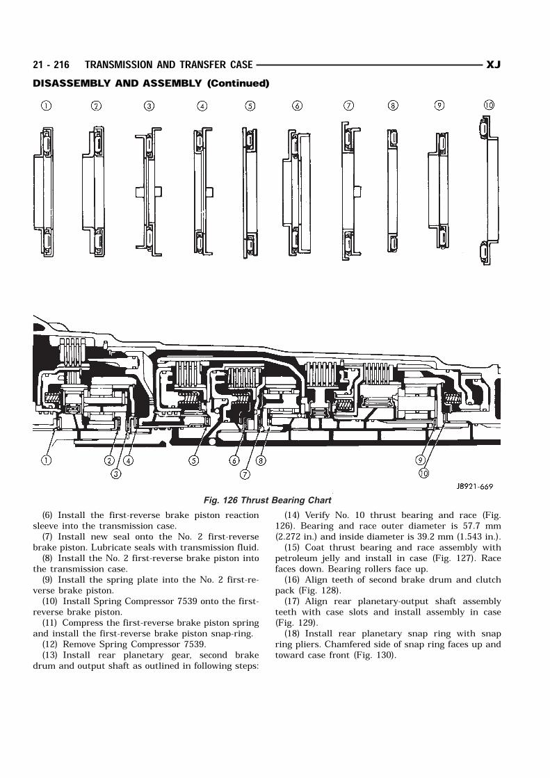
(6) Install the first-reverse brake piston reactionsleeve into the transmission case.(7) Install new seal onto the No. 2 first-reverse
brake piston. Lubricate seals with transmission fluid.(8) Install the No. 2 first-reverse brake piston into
the transmission case.(9) Install the spring plate into the No. 2 first-re-
verse brake piston.(10) Install Spring Compressor 7539 onto the first-
reverse brake piston.(11) Compress the first-reverse brake piston spring
and install the first-reverse brake piston snap-ring.(12) Remove Spring Compressor 7539.(13) Install rear planetary gear, second brake
drum and output shaft as outlined in following steps:
(14) Verify No. 10 thrust bearing and race (Fig.126). Bearing and race outer diameter is 57.7 mm(2.272 in.) and inside diameter is 39.2 mm (1.543 in.).(15) Coat thrust bearing and race assembly with
petroleum jelly and install in case (Fig. 127). Racefaces down. Bearing rollers face up.(16) Align teeth of second brake drum and clutch
pack (Fig. 128).(17) Align rear planetary-output shaft assembly
teeth with case slots and install assembly in case(Fig. 129).(18) Install rear planetary snap ring with snap
ring pliers. Chamfered side of snap ring faces up andtoward case front (Fig. 130).
Fig. 126 Thrust Bearing Chart
21 - 216 TRANSMISSION AND TRANSFER CASE XJDISASSEMBLY AND ASSEMBLY (Continued)
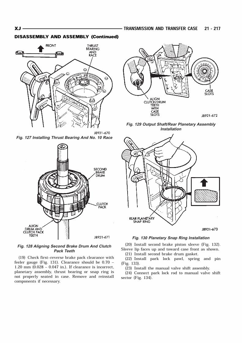
(19) Check first–reverse brake pack clearance withfeeler gauge (Fig. 131). Clearance should be 0.70 –1.20 mm (0.028 – 0.047 in.). If clearance is incorrect,planetary assembly, thrust bearing or snap ring isnot properly seated in case. Remove and reinstallcomponents if necessary.
(20) Install second brake piston sleeve (Fig. 132).Sleeve lip faces up and toward case front as shown.(21) Install second brake drum gasket.(22) Install park lock pawl, spring and pin
(Fig. 133).(23) Install the manual valve shift assembly.(24) Connect park lock rod to manual valve shift
sector (Fig. 134).
Fig. 127 Installing Thrust Bearing And No. 10 Race
Fig. 128 Aligning Second Brake Drum And Clutch
Pack Teeth
Fig. 129 Output Shaft/Rear Planetary Assembly
Installation
Fig. 130 Planetary Snap Ring Installation
XJ TRANSMISSION AND TRANSFER CASE 21 - 217DISASSEMBLY AND ASSEMBLY (Continued)
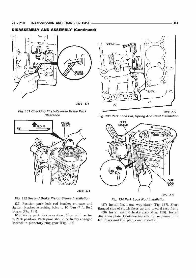
(25) Position park lock rod bracket on case andtighten bracket attaching bolts to 10 N·m (7 ft. lbs.)torque (Fig. 135).(26) Verify park lock operation. Move shift sector
to Park position. Park pawl should be firmly engaged(locked) in planetary ring gear (Fig. 136).
(27) Install No. 1 one–way clutch (Fig. 137). Shortflanged side of clutch faces up and toward case front.(28) Install second brake pack (Fig. 138). Install
disc then plate. Continue installation sequence untilfive discs and five plates are installed.
Fig. 131 Checking First–Reverse Brake Pack
Clearance
Fig. 132 Second Brake Piston Sleeve Installation
Fig. 133 Park Lock Pin, Spring And Pawl Installation
Fig. 134 Park Lock Rod Installation
21 - 218 TRANSMISSION AND TRANSFER CASE XJDISASSEMBLY AND ASSEMBLY (Continued)
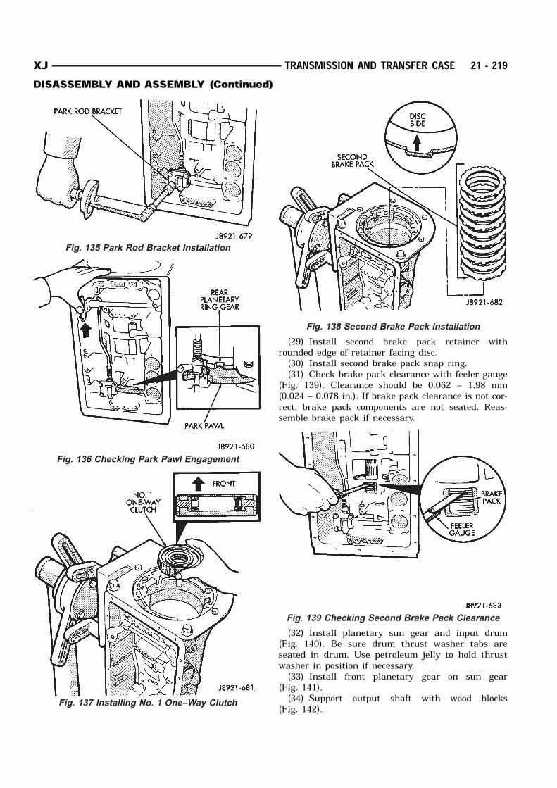
(29) Install second brake pack retainer withrounded edge of retainer facing disc.(30) Install second brake pack snap ring.(31) Check brake pack clearance with feeler gauge
(Fig. 139). Clearance should be 0.062 – 1.98 mm(0.024 – 0.078 in.). If brake pack clearance is not cor-rect, brake pack components are not seated. Reas-semble brake pack if necessary.
(32) Install planetary sun gear and input drum(Fig. 140). Be sure drum thrust washer tabs areseated in drum. Use petroleum jelly to hold thrustwasher in position if necessary.(33) Install front planetary gear on sun gear
(Fig. 141).(34) Support output shaft with wood blocks
(Fig. 142).
Fig. 135 Park Rod Bracket Installation
Fig. 136 Checking Park Pawl Engagement
Fig. 137 Installing No. 1 One–Way Clutch
Fig. 138 Second Brake Pack Installation
Fig. 139 Checking Second Brake Pack Clearance
XJ TRANSMISSION AND TRANSFER CASE 21 - 219DISASSEMBLY AND ASSEMBLY (Continued)
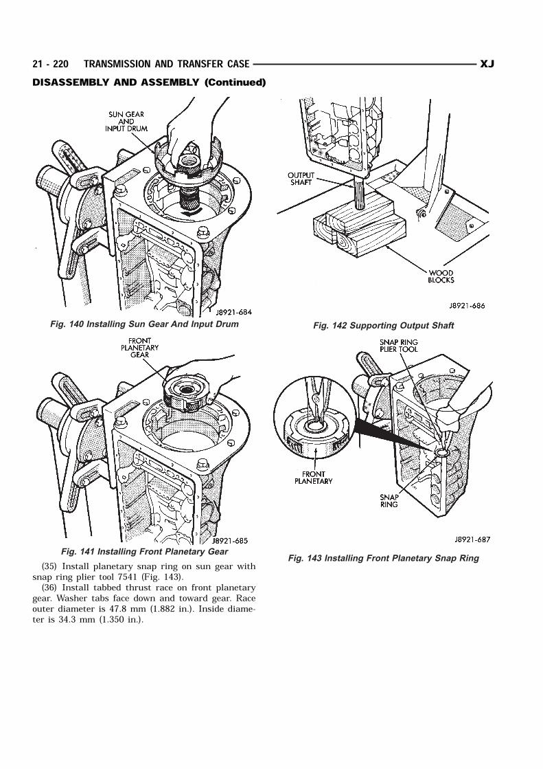
(35) Install planetary snap ring on sun gear withsnap ring plier tool 7541 (Fig. 143).(36) Install tabbed thrust race on front planetary
gear. Washer tabs face down and toward gear. Raceouter diameter is 47.8 mm (1.882 in.). Inside diame-ter is 34.3 mm (1.350 in.).
Fig. 140 Installing Sun Gear And Input Drum
Fig. 141 Installing Front Planetary Gear
Fig. 142 Supporting Output Shaft
Fig. 143 Installing Front Planetary Snap Ring
21 - 220 TRANSMISSION AND TRANSFER CASE XJDISASSEMBLY AND ASSEMBLY (Continued)

(37) Install second coast brake band (Fig. 144).
(38) Install pin in second coast brake band. Theninstall retaining ring on pin (Fig. 145).(39) Install thrust bearing and race in forward–di-
rect clutch (Fig. 146). Coat bearing/race with petro-leum jelly to hold them in place.(40) Verify forward–direct clutch thrust bearing
size. Race outer diameter is 48.9 mm (1.925 in.) and
inside diameter is 26.0 mm (1.024 in.). Bearing outer diameter is 46.7 mm (1.839 in.)
and inside diameter is 26.0 mm (1.024 in.).(41) Coat front planetary ring gear race with
petroleum jelly and install it in ring gear (Fig. 147).(42) Verify ring gear race size. Outer diameter is
47.0 mm (1.850 in.) and inside diameter is 26.5 mm(1.045 in.).(43) Align forward–direct clutch disc splines with
screwdriver (Fig. 148).(44) Align and install front planetary ring gear in
forward–direct clutch (Fig. 149).(45) Coat bearing and race with petroleum jelly
and install them in ring gear (Fig. 150). Verify bear-ing/race size.
Fig. 144 Installing Second Coast Brake Band
Fig. 145 Installing Second Coast Brake Band
Retaining Pin
XJ TRANSMISSION AND TRANSFER CASE 21 - 221DISASSEMBLY AND ASSEMBLY (Continued)
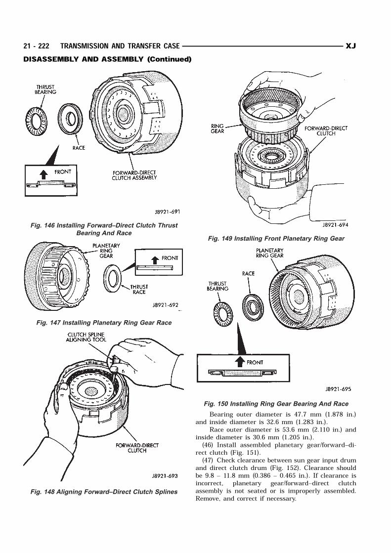
Bearing outer diameter is 47.7 mm (1.878 in.)and inside diameter is 32.6 mm (1.283 in.).
Race outer diameter is 53.6 mm (2.110 in.) andinside diameter is 30.6 mm (1.205 in.).(46) Install assembled planetary gear/forward–di-
rect clutch (Fig. 151).(47) Check clearance between sun gear input drum
and direct clutch drum (Fig. 152). Clearance shouldbe 9.8 – 11.8 mm (0.386 – 0.465 in.). If clearance isincorrect, planetary gear/forward–direct clutchassembly is not seated or is improperly assembled.Remove, and correct if necessary.
Fig. 146 Installing Forward–Direct Clutch Thrust
Bearing And Race
Fig. 147 Installing Planetary Ring Gear Race
Fig. 148 Aligning Forward–Direct Clutch Splines
Fig. 149 Installing Front Planetary Ring Gear
Fig. 150 Installing Ring Gear Bearing And Race
21 - 222 TRANSMISSION AND TRANSFER CASE XJDISASSEMBLY AND ASSEMBLY (Continued)
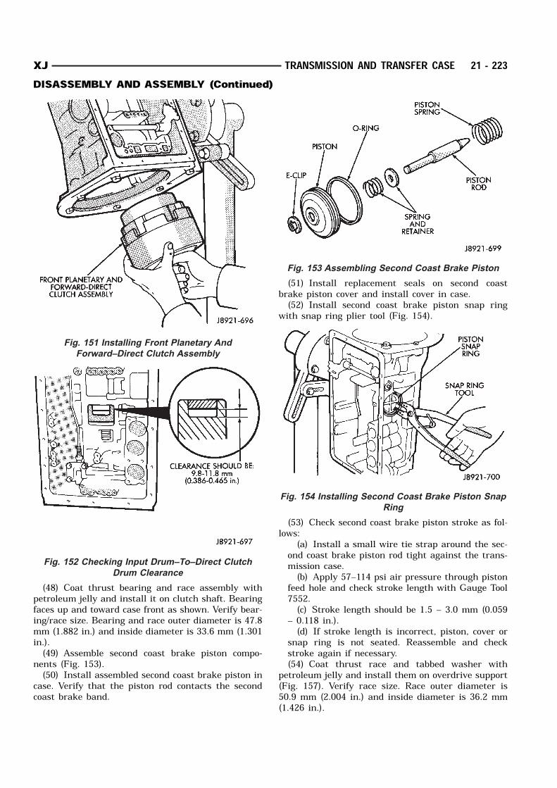
(48) Coat thrust bearing and race assembly withpetroleum jelly and install it on clutch shaft. Bearingfaces up and toward case front as shown. Verify bear-ing/race size. Bearing and race outer diameter is 47.8mm (1.882 in.) and inside diameter is 33.6 mm (1.301in.).(49) Assemble second coast brake piston compo-
nents (Fig. 153).(50) Install assembled second coast brake piston in
case. Verify that the piston rod contacts the secondcoast brake band.
(51) Install replacement seals on second coastbrake piston cover and install cover in case.(52) Install second coast brake piston snap ring
with snap ring plier tool (Fig. 154).
(53) Check second coast brake piston stroke as fol-lows:
(a) Install a small wire tie strap around the sec-ond coast brake piston rod tight against the trans-mission case.(b) Apply 57–114 psi air pressure through piston
feed hole and check stroke length with Gauge Tool7552.(c) Stroke length should be 1.5 – 3.0 mm (0.059
– 0.118 in.).(d) If stroke length is incorrect, piston, cover or
snap ring is not seated. Reassemble and checkstroke again if necessary.(54) Coat thrust race and tabbed washer with
petroleum jelly and install them on overdrive support(Fig. 157). Verify race size. Race outer diameter is50.9 mm (2.004 in.) and inside diameter is 36.2 mm(1.426 in.).
Fig. 151 Installing Front Planetary And
Forward–Direct Clutch Assembly
Fig. 152 Checking Input Drum–To–Direct Clutch
Drum Clearance
Fig. 153 Assembling Second Coast Brake Piston
Fig. 154 Installing Second Coast Brake Piston Snap
Ring
XJ TRANSMISSION AND TRANSFER CASE 21 - 223DISASSEMBLY AND ASSEMBLY (Continued)
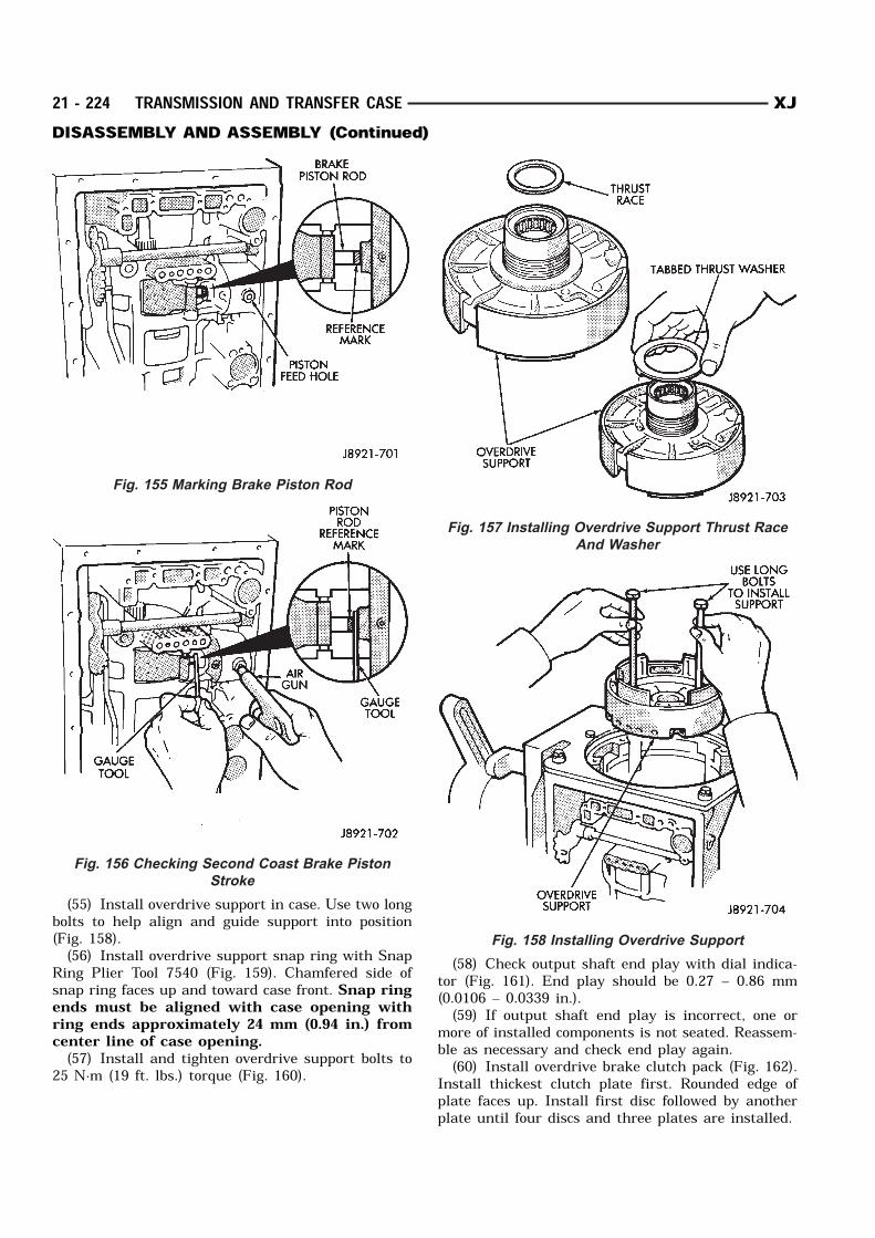
(55) Install overdrive support in case. Use two longbolts to help align and guide support into position(Fig. 158).(56) Install overdrive support snap ring with Snap
Ring Plier Tool 7540 (Fig. 159). Chamfered side ofsnap ring faces up and toward case front. Snap ringends must be aligned with case opening withring ends approximately 24 mm (0.94 in.) fromcenter line of case opening.(57) Install and tighten overdrive support bolts to
25 N·m (19 ft. lbs.) torque (Fig. 160).
(58) Check output shaft end play with dial indica-tor (Fig. 161). End play should be 0.27 – 0.86 mm(0.0106 – 0.0339 in.).(59) If output shaft end play is incorrect, one or
more of installed components is not seated. Reassem-ble as necessary and check end play again.(60) Install overdrive brake clutch pack (Fig. 162).
Install thickest clutch plate first. Rounded edge ofplate faces up. Install first disc followed by anotherplate until four discs and three plates are installed.
Fig. 155 Marking Brake Piston Rod
Fig. 156 Checking Second Coast Brake Piston
Stroke
Fig. 157 Installing Overdrive Support Thrust Race
And Washer
Fig. 158 Installing Overdrive Support
21 - 224 TRANSMISSION AND TRANSFER CASE XJDISASSEMBLY AND ASSEMBLY (Continued)

(61) Install stepped ring retainer plate with flatside facing disc. Then install brake pack snap ring(Fig. 163).
(62) Check overdrive brake piston stroke as fol-lows:
(a) Mount dial indicator on case using MillerTool C-3339 and a suitable bolt threaded into thetransmission case.(b) Verify that the dial indicator is mounted sol-
idly and square to the direction of the pistontravel.
Fig. 159 Installing Overdrive Support Snap Ring
Fig. 160 Installing Overdrive Support Bolts
Fig. 161 Checking Output Shaft End Play
Fig. 162 Installing Overdrive Brake Clutch Pack
Fig. 163 Installing Overdrive Brake Snap Ring
XJ TRANSMISSION AND TRANSFER CASE 21 - 225DISASSEMBLY AND ASSEMBLY (Continued)
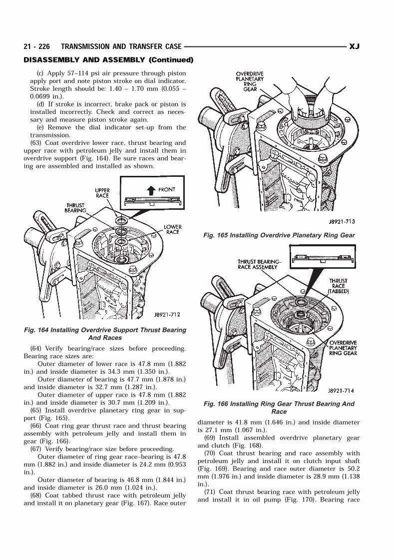
(c) Apply 57–114 psi air pressure through pistonapply port and note piston stroke on dial indicator.Stroke length should be: 1.40 – 1.70 mm (0.055 –0.0699 in.).(d) If stroke is incorrect, brake pack or piston is
installed incorrectly. Check and correct as neces-sary and measure piston stroke again.(e) Remove the dial indicator set-up from the
transmission.(63) Coat overdrive lower race, thrust bearing and
upper race with petroleum jelly and install them inoverdrive support (Fig. 164). Be sure races and bear-ing are assembled and installed as shown.
(64) Verify bearing/race sizes before proceeding.Bearing race sizes are:
Outer diameter of lower race is 47.8 mm (1.882in.) and inside diameter is 34.3 mm (1.350 in.).
Outer diameter of bearing is 47.7 mm (1.878 in.)and inside diameter is 32.7 mm (1.287 in.).
Outer diameter of upper race is 47.8 mm (1.882in.) and inside diameter is 30.7 mm (1.209 in.).(65) Install overdrive planetary ring gear in sup-
port (Fig. 165).(66) Coat ring gear thrust race and thrust bearing
assembly with petroleum jelly and install them ingear (Fig. 166).(67) Verify bearing/race size before proceeding. Outer diameter of ring gear race–bearing is 47.8
mm (1.882 in.) and inside diameter is 24.2 mm (0.953in.).
Outer diameter of bearing is 46.8 mm (1.844 in.)and inside diameter is 26.0 mm (1.024 in.).(68) Coat tabbed thrust race with petroleum jelly
and install it on planetary gear (Fig. 167). Race outer
diameter is 41.8 mm (1.646 in.) and inside diameteris 27.1 mm (1.067 in.).(69) Install assembled overdrive planetary gear
and clutch (Fig. 168).(70) Coat thrust bearing and race assembly with
petroleum jelly and install it on clutch input shaft(Fig. 169). Bearing and race outer diameter is 50.2mm (1.976 in.) and inside diameter is 28.9 mm (1.138in.).(71) Coat thrust bearing race with petroleum jelly
and install it in oil pump (Fig. 170). Bearing race
Fig. 164 Installing Overdrive Support Thrust Bearing
And Races
Fig. 165 Installing Overdrive Planetary Ring Gear
Fig. 166 Installing Ring Gear Thrust Bearing And
Race
21 - 226 TRANSMISSION AND TRANSFER CASE XJDISASSEMBLY AND ASSEMBLY (Continued)
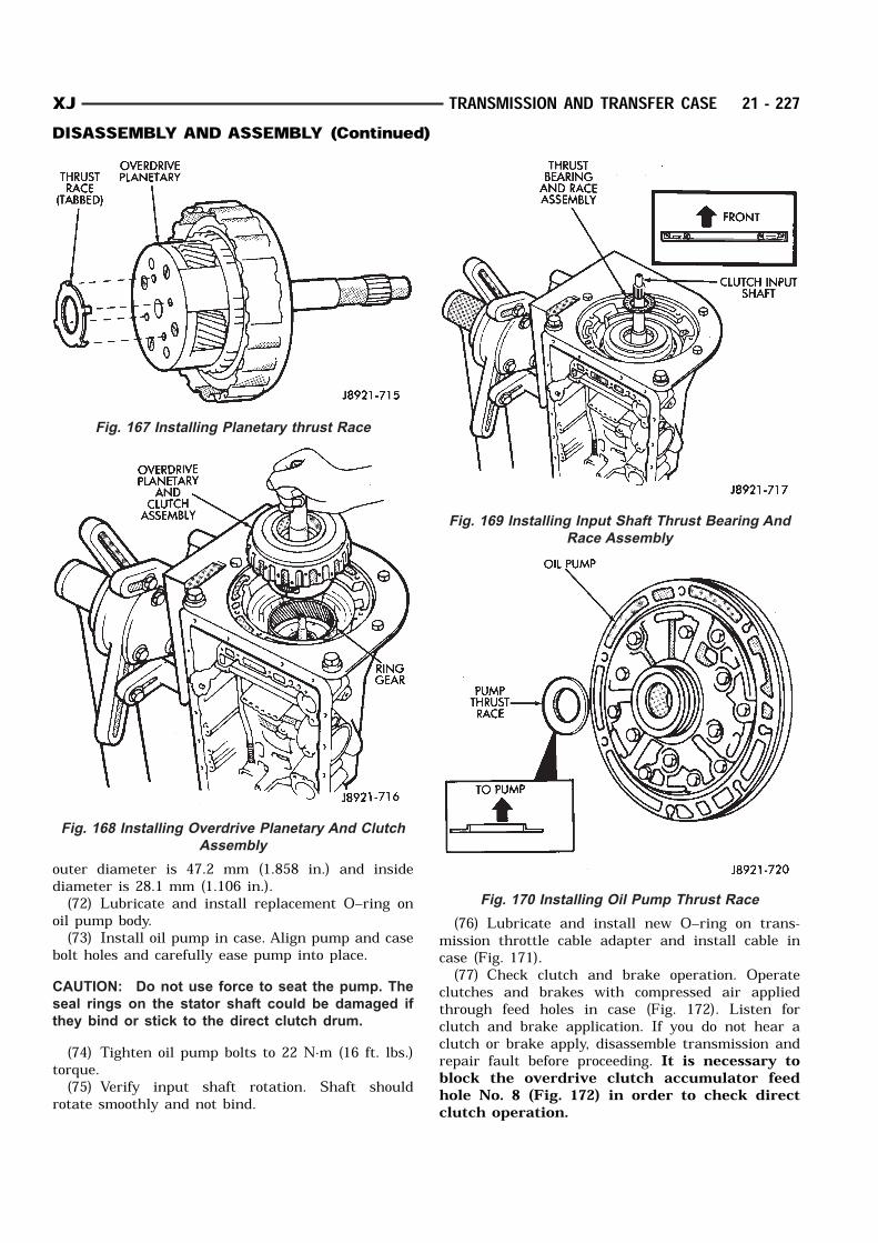
outer diameter is 47.2 mm (1.858 in.) and insidediameter is 28.1 mm (1.106 in.).(72) Lubricate and install replacement O–ring on
oil pump body.(73) Install oil pump in case. Align pump and case
bolt holes and carefully ease pump into place.CAUTION: Do not use force to seat the pump. The
seal rings on the stator shaft could be damaged if
they bind or stick to the direct clutch drum.
(74) Tighten oil pump bolts to 22 N·m (16 ft. lbs.)torque.(75) Verify input shaft rotation. Shaft should
rotate smoothly and not bind.
(76) Lubricate and install new O–ring on trans-mission throttle cable adapter and install cable incase (Fig. 171).(77) Check clutch and brake operation. Operate
clutches and brakes with compressed air appliedthrough feed holes in case (Fig. 172). Listen forclutch and brake application. If you do not hear aclutch or brake apply, disassemble transmission andrepair fault before proceeding. It is necessary toblock the overdrive clutch accumulator feedhole No. 8 (Fig. 172) in order to check directclutch operation.
Fig. 167 Installing Planetary thrust Race
Fig. 168 Installing Overdrive Planetary And Clutch
Assembly
Fig. 169 Installing Input Shaft Thrust Bearing And
Race Assembly
Fig. 170 Installing Oil Pump Thrust Race
XJ TRANSMISSION AND TRANSFER CASE 21 - 227DISASSEMBLY AND ASSEMBLY (Continued)
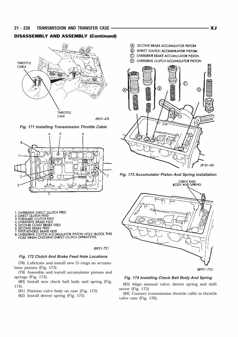
(78) Lubricate and install new O–rings on accumu-lator pistons (Fig. 173).(79) Assemble and install accumulator pistons and
springs (Fig. 173).(80) Install new check ball body and spring (Fig.
174).(81) Position valve body on case (Fig. 175).(82) Install detent spring (Fig. 175).
(83) Align manual valve, detent spring and shiftsector (Fig. 175).(84) Connect transmission throttle cable to throttle
valve cam (Fig. 176).
Fig. 171 Installing Transmission Throttle Cable
Fig. 172 Clutch And Brake Feed Hole Locations
Fig. 173 Accumulator Piston And Spring Installation
Fig. 174 Installing Check Ball Body And Spring
21 - 228 TRANSMISSION AND TRANSFER CASE XJDISASSEMBLY AND ASSEMBLY (Continued)
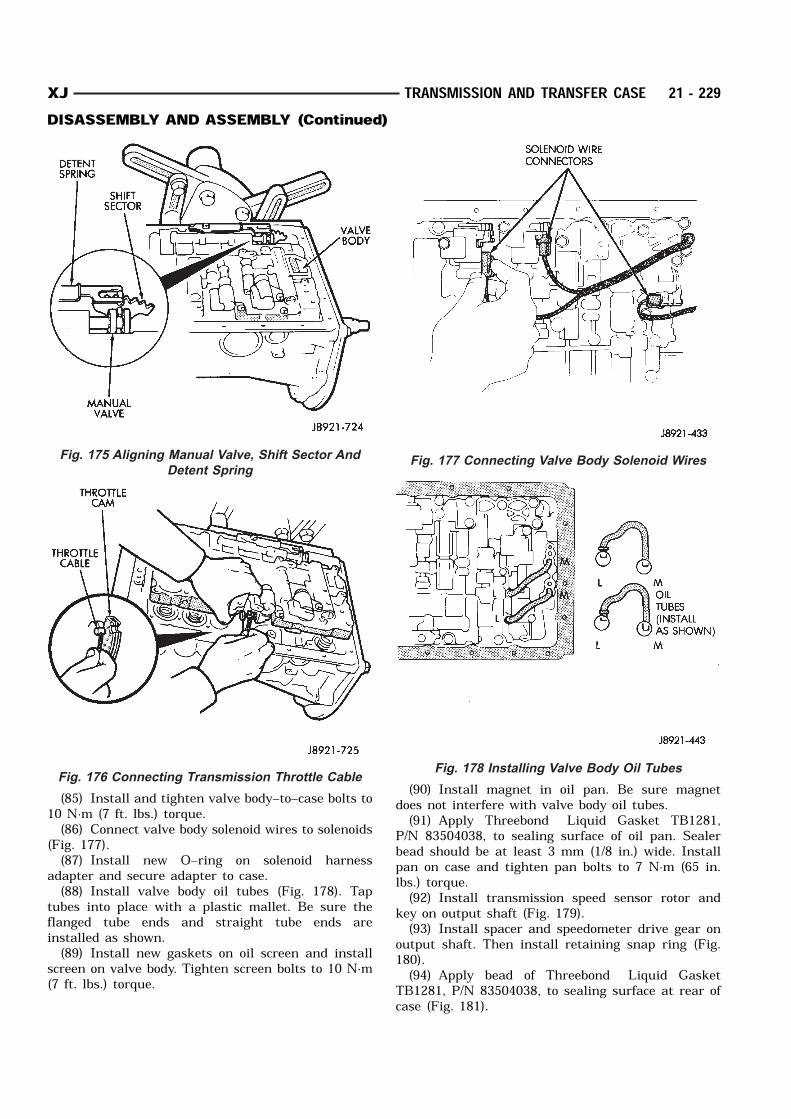
(85) Install and tighten valve body–to–case bolts to10 N·m (7 ft. lbs.) torque.(86) Connect valve body solenoid wires to solenoids
(Fig. 177).(87) Install new O–ring on solenoid harness
adapter and secure adapter to case.(88) Install valve body oil tubes (Fig. 178). Tap
tubes into place with a plastic mallet. Be sure theflanged tube ends and straight tube ends areinstalled as shown.(89) Install new gaskets on oil screen and install
screen on valve body. Tighten screen bolts to 10 N·m(7 ft. lbs.) torque.
(90) Install magnet in oil pan. Be sure magnetdoes not interfere with valve body oil tubes.(91) Apply Threebond Liquid Gasket TB1281,
P/N 83504038, to sealing surface of oil pan. Sealerbead should be at least 3 mm (1/8 in.) wide. Installpan on case and tighten pan bolts to 7 N·m (65 in.lbs.) torque.(92) Install transmission speed sensor rotor and
key on output shaft (Fig. 179).(93) Install spacer and speedometer drive gear on
output shaft. Then install retaining snap ring (Fig.180).(94) Apply bead of Threebond Liquid Gasket
TB1281, P/N 83504038, to sealing surface at rear ofcase (Fig. 181).
Fig. 175 Aligning Manual Valve, Shift Sector And
Detent Spring
Fig. 176 Connecting Transmission Throttle Cable
Fig. 177 Connecting Valve Body Solenoid Wires
Fig. 178 Installing Valve Body Oil Tubes
XJ TRANSMISSION AND TRANSFER CASE 21 - 229DISASSEMBLY AND ASSEMBLY (Continued)
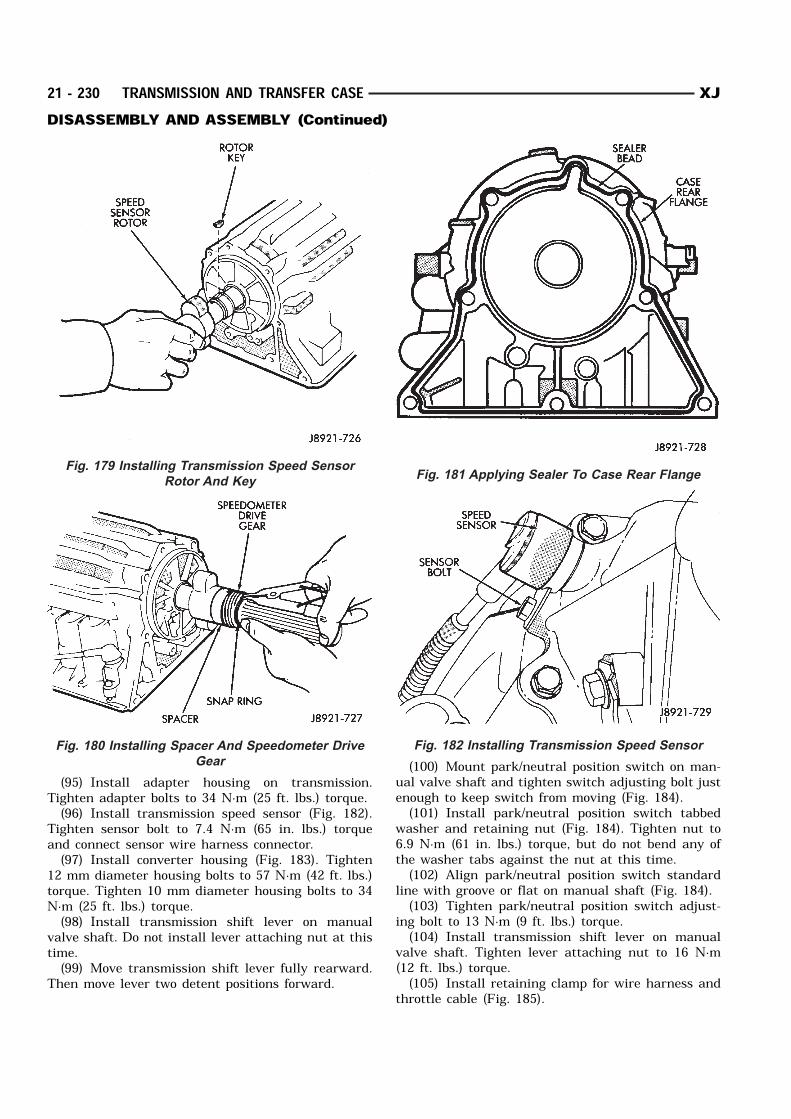
(95) Install adapter housing on transmission.Tighten adapter bolts to 34 N·m (25 ft. lbs.) torque.(96) Install transmission speed sensor (Fig. 182).
Tighten sensor bolt to 7.4 N·m (65 in. lbs.) torqueand connect sensor wire harness connector.(97) Install converter housing (Fig. 183). Tighten
12 mm diameter housing bolts to 57 N·m (42 ft. lbs.)torque. Tighten 10 mm diameter housing bolts to 34N·m (25 ft. lbs.) torque.(98) Install transmission shift lever on manual
valve shaft. Do not install lever attaching nut at thistime.(99) Move transmission shift lever fully rearward.
Then move lever two detent positions forward.
(100) Mount park/neutral position switch on man-ual valve shaft and tighten switch adjusting bolt justenough to keep switch from moving (Fig. 184).(101) Install park/neutral position switch tabbed
washer and retaining nut (Fig. 184). Tighten nut to6.9 N·m (61 in. lbs.) torque, but do not bend any ofthe washer tabs against the nut at this time.(102) Align park/neutral position switch standard
line with groove or flat on manual shaft (Fig. 184).(103) Tighten park/neutral position switch adjust-
ing bolt to 13 N·m (9 ft. lbs.) torque.(104) Install transmission shift lever on manual
valve shaft. Tighten lever attaching nut to 16 N·m(12 ft. lbs.) torque.(105) Install retaining clamp for wire harness and
throttle cable (Fig. 185).
Fig. 179 Installing Transmission Speed Sensor
Rotor And Key
Fig. 180 Installing Spacer And Speedometer Drive
Gear
Fig. 181 Applying Sealer To Case Rear Flange
Fig. 182 Installing Transmission Speed Sensor
21 - 230 TRANSMISSION AND TRANSFER CASE XJDISASSEMBLY AND ASSEMBLY (Continued)
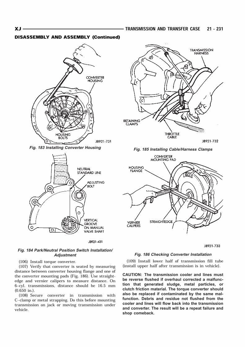
(106) Install torque converter.(107) Verify that converter is seated by measuring
distance between converter housing flange and one ofthe converter mounting pads (Fig. 186). Use straight-edge and vernier calipers to measure distance. On6–cyl. transmissions, distance should be 16.5 mm(0.650 in.).(108) Secure converter in transmission with
C–clamp or metal strapping. Do this before mountingtransmission on jack or moving transmission undervehicle.
(109) Install lower half of transmission fill tube(install upper half after transmission is in vehicle).CAUTION: The transmission cooler and lines must
be reverse flushed if overhaul corrected a malfunc-
tion that generated sludge, metal particles, or
clutch friction material. The torque converter should
also be replaced if contaminated by the same mal-
function. Debris and residue not flushed from the
cooler and lines will flow back into the transmission
and converter. The result will be a repeat failure and
shop comeback.
Fig. 183 Installing Converter Housing
Fig. 184 Park/Neutral Position Switch Installation/
Adjustment
Fig. 185 Installing Cable/Harness Clamps
Fig. 186 Checking Converter Installation
XJ TRANSMISSION AND TRANSFER CASE 21 - 231DISASSEMBLY AND ASSEMBLY (Continued)
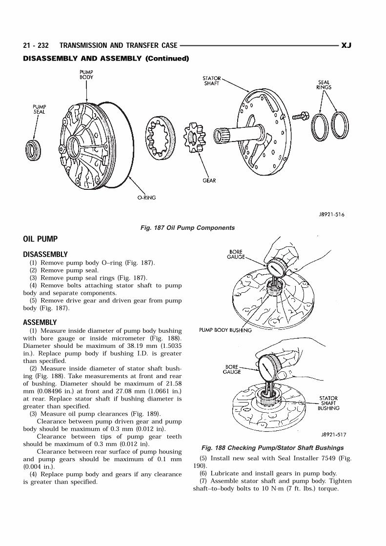
OIL PUMPDISASSEMBLY(1) Remove pump body O–ring (Fig. 187).(2) Remove pump seal.(3) Remove pump seal rings (Fig. 187).(4) Remove bolts attaching stator shaft to pump
body and separate components.(5) Remove drive gear and driven gear from pump
body (Fig. 187).ASSEMBLY(1) Measure inside diameter of pump body bushing
with bore gauge or inside micrometer (Fig. 188).Diameter should be maximum of 38.19 mm (1.5035in.). Replace pump body if bushing I.D. is greaterthan specified.(2) Measure inside diameter of stator shaft bush-
ing (Fig. 188). Take measurements at front and rearof bushing. Diameter should be maximum of 21.58mm (0.08496 in.) at front and 27.08 mm (1.0661 in.)at rear. Replace stator shaft if bushing diameter isgreater than specified.(3) Measure oil pump clearances (Fig. 189). Clearance between pump driven gear and pump
body should be maximum of 0.3 mm (0.012 in). Clearance between tips of pump gear teeth
should be maximum of 0.3 mm (0.012 in). Clearance between rear surface of pump housing
and pump gears should be maximum of 0.1 mm(0.004 in.).(4) Replace pump body and gears if any clearance
is greater than specified.
(5) Install new seal with Seal Installer 7549 (Fig.190).(6) Lubricate and install gears in pump body.(7) Assemble stator shaft and pump body. Tighten
shaft–to–body bolts to 10 N·m (7 ft. lbs.) torque.
Fig. 187 Oil Pump Components
Fig. 188 Checking Pump/Stator Shaft Bushings
21 - 232 TRANSMISSION AND TRANSFER CASE XJDISASSEMBLY AND ASSEMBLY (Continued)

(8) Install new O–ring on pump body and new sealrings on stator shaft.(9) Install pump in torque converter and check
pump gear rotation (Fig. 191). Gears must rotatesmoothly when turned clockwise and counterclock-wise.(10) Lubricate pump O–ring and seal rings with
petroleum jelly.
Fig. 189 Checking Pump Gear Clearances
Fig. 190 Installing Pump Seal
Fig. 191 Checking Pump Gear Rotation
XJ TRANSMISSION AND TRANSFER CASE 21 - 233DISASSEMBLY AND ASSEMBLY (Continued)
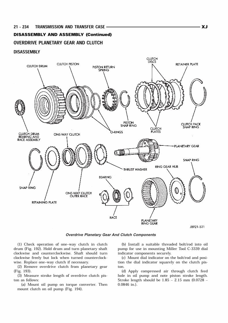
OVERDRIVE PLANETARY GEAR AND CLUTCHDISASSEMBLY
(1) Check operation of one–way clutch in clutchdrum (Fig. 192). Hold drum and turn planetary shaftclockwise and counterclockwise. Shaft should turnclockwise freely but lock when turned counterclock-wise. Replace one–way clutch if necessary.(2) Remove overdrive clutch from planetary gear
(Fig. 193).(3) Measure stroke length of overdrive clutch pis-
ton as follows:(a) Mount oil pump on torque converter. Then
mount clutch on oil pump (Fig. 194).
(b) Install a suitable threaded bolt/rod into oilpump for use in mounting Miller Tool C-3339 dialindicator components securely.(c) Mount dial indicator on the bolt/rod and posi-
tion the dial indicator squarely on the clutch pis-ton.(d) Apply compressed air through clutch feed
hole in oil pump and note piston stroke length.Stroke length should be 1.85 – 2.15 mm (0.0728 –0.0846 in.).
Overdrive Planetary Gear And Clutch Components
21 - 234 TRANSMISSION AND TRANSFER CASE XJDISASSEMBLY AND ASSEMBLY (Continued)
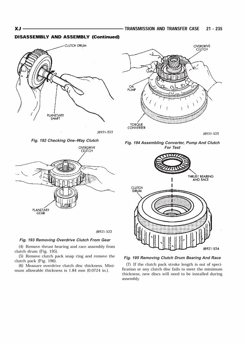
(4) Remove thrust bearing and race assembly fromclutch drum (Fig. 195).(5) Remove clutch pack snap ring and remove the
clutch pack (Fig. 196).(6) Measure overdrive clutch disc thickness. Mini-
mum allowable thickness is 1.84 mm (0.0724 in.).(7) If the clutch pack stroke length is out of speci-
fication or any clutch disc fails to meet the minimumthickness, new discs will need to be installed duringassembly.
Fig. 192 Checking One–Way Clutch
Fig. 193 Removing Overdrive Clutch From Gear
Fig. 194 Assembling Converter, Pump And Clutch
For Test
Fig. 195 Removing Clutch Drum Bearing And Race
XJ TRANSMISSION AND TRANSFER CASE 21 - 235DISASSEMBLY AND ASSEMBLY (Continued)
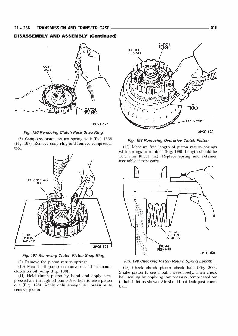
(8) Compress piston return spring with Tool 7538(Fig. 197). Remove snap ring and remove compressortool.
(9) Remove the piston return springs.(10) Mount oil pump on converter. Then mount
clutch on oil pump (Fig. 198).(11) Hold clutch piston by hand and apply com-
pressed air through oil pump feed hole to ease pistonout (Fig. 198). Apply only enough air pressure toremove piston.
(12) Measure free length of piston return springswith springs in retainer (Fig. 199). Length should be16.8 mm (0.661 in.). Replace spring and retainerassembly if necessary.
(13) Check clutch piston check ball (Fig. 200).Shake piston to see if ball moves freely. Then checkball sealing by applying low pressure compressed airto ball inlet as shown. Air should not leak past checkball.
Fig. 196 Removing Clutch Pack Snap Ring
Fig. 197 Removing Clutch Piston Snap Ring
Fig. 198 Removing Overdrive Clutch Piston
Fig. 199 Checking Piston Return Spring Length
21 - 236 TRANSMISSION AND TRANSFER CASE XJDISASSEMBLY AND ASSEMBLY (Continued)
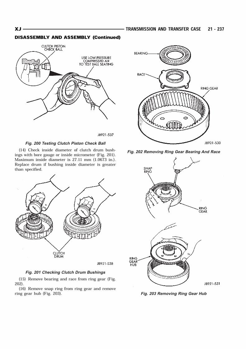
(14) Check inside diameter of clutch drum bush-ings with bore gauge or inside micrometer (Fig. 201).Maximum inside diameter is 27.11 mm (1.0673 in.).Replace drum if bushing inside diameter is greaterthan specified.
(15) Remove bearing and race from ring gear (Fig.202).(16) Remove snap ring from ring gear and remove
ring gear hub (Fig. 203).
Fig. 200 Testing Clutch Piston Check Ball
Fig. 201 Checking Clutch Drum Bushings
Fig. 202 Removing Ring Gear Bearing And Race
Fig. 203 Removing Ring Gear Hub
XJ TRANSMISSION AND TRANSFER CASE 21 - 237DISASSEMBLY AND ASSEMBLY (Continued)
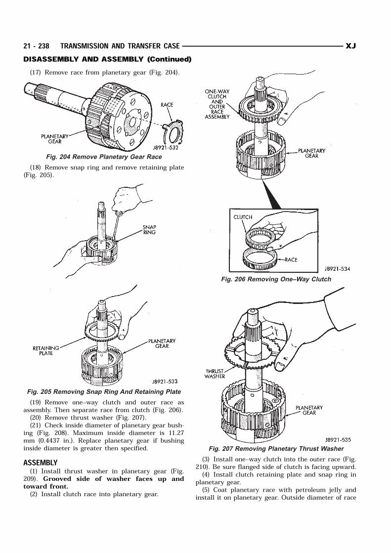
(17) Remove race from planetary gear (Fig. 204).
(18) Remove snap ring and remove retaining plate(Fig. 205).
(19) Remove one–way clutch and outer race asassembly. Then separate race from clutch (Fig. 206).(20) Remove thrust washer (Fig. 207).(21) Check inside diameter of planetary gear bush-
ing (Fig. 208). Maximum inside diameter is 11.27mm (0.4437 in.). Replace planetary gear if bushinginside diameter is greater then specified.ASSEMBLY(1) Install thrust washer in planetary gear (Fig.
209). Grooved side of washer faces up andtoward front.(2) Install clutch race into planetary gear.
(3) Install one–way clutch into the outer race (Fig.210). Be sure flanged side of clutch is facing upward.(4) Install clutch retaining plate and snap ring in
planetary gear.(5) Coat planetary race with petroleum jelly and
install it on planetary gear. Outside diameter of race
Fig. 204 Remove Planetary Gear Race
Fig. 205 Removing Snap Ring And Retaining Plate
Fig. 206 Removing One–Way Clutch
Fig. 207 Removing Planetary Thrust Washer
21 - 238 TRANSMISSION AND TRANSFER CASE XJDISASSEMBLY AND ASSEMBLY (Continued)
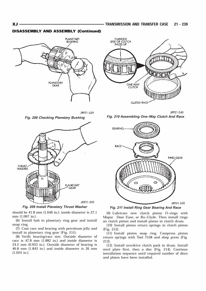
should be 41.8 mm (1.646 in.); inside diameter is 27.1mm (1.067 in.).(6) Install hub in planetary ring gear and install
snap ring.(7) Coat race and bearing with petroleum jelly and
install in planetary ring gear (Fig. 211).(8) Verify bearing/race size. Outside diameter of
race is 47.8 mm (1.882 in.) and inside diameter is24.2 mm (0.953 in.). Outside diameter of bearing is46.8 mm (1.843 in.) and inside diameter is 26 mm(1.024 in.).
(9) Lubricate new clutch piston O–rings withMopar Door Ease, or Ru–Glyde. Then install ringson clutch piston and install piston in clutch drum.(10) Install piston return springs in clutch piston
(Fig. 212).(11) Install piston snap ring. Compress piston
return springs with Tool 7538 and shop press (Fig.213).(12) Install overdrive clutch pack in drum. Install
steel plate first, then a disc (Fig. 214). Continueinstallation sequence until required number of discsand plates have been installed.
Fig. 208 Checking Planetary Bushing
Fig. 209 Install Planetary Thrust Washer
Fig. 210 Assembling One–Way Clutch And Race
Fig. 211 Install Ring Gear Bearing And Race
XJ TRANSMISSION AND TRANSFER CASE 21 - 239DISASSEMBLY AND ASSEMBLY (Continued)
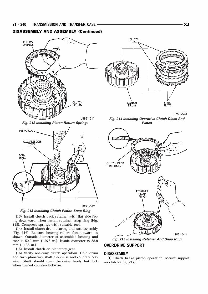
(13) Install clutch pack retainer with flat side fac-ing downward. Then install retainer snap ring (Fig.215). Compress springs with suitable tool.(14) Install clutch drum bearing and race assembly
(Fig. 216). Be sure bearing rollers face upward asshown. Outside diameter of assembled bearing andrace is 50.2 mm (1.976 in.). Inside diameter is 28.9mm (1.138 in.).(15) Install clutch on planetary gear.(16) Verify one–way clutch operation. Hold drum
and turn planetary shaft clockwise and counterclock-wise. Shaft should turn clockwise freely but lockwhen turned counterclockwise.
OVERDRIVE SUPPORTDISASSEMBLY(1) Check brake piston operation. Mount support
on clutch (Fig. 217).
Fig. 212 Installing Piston Return Springs
Fig. 213 Installing Clutch Piston Snap Ring
Fig. 214 Installing Overdrive Clutch Discs And
Plates
Fig. 215 Installing Retainer And Snap Ring
21 - 240 TRANSMISSION AND TRANSFER CASE XJDISASSEMBLY AND ASSEMBLY (Continued)
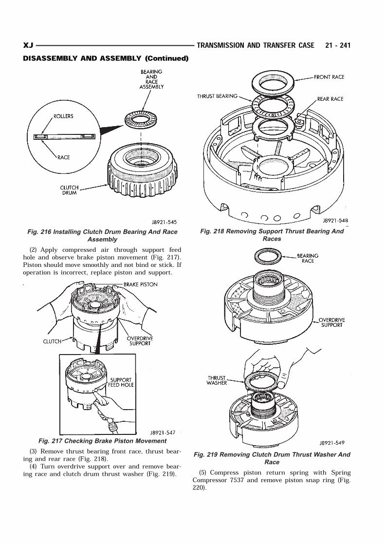
(2) Apply compressed air through support feedhole and observe brake piston movement (Fig. 217).Piston should move smoothly and not bind or stick. Ifoperation is incorrect, replace piston and support.
(3) Remove thrust bearing front race, thrust bear-ing and rear race (Fig. 218).(4) Turn overdrive support over and remove bear-
ing race and clutch drum thrust washer (Fig. 219). (5) Compress piston return spring with SpringCompressor 7537 and remove piston snap ring (Fig.220).
Fig. 216 Installing Clutch Drum Bearing And Race
Assembly
Fig. 217 Checking Brake Piston Movement
Fig. 218 Removing Support Thrust Bearing And
Races
Fig. 219 Removing Clutch Drum Thrust Washer And
Race
XJ TRANSMISSION AND TRANSFER CASE 21 - 241DISASSEMBLY AND ASSEMBLY (Continued)
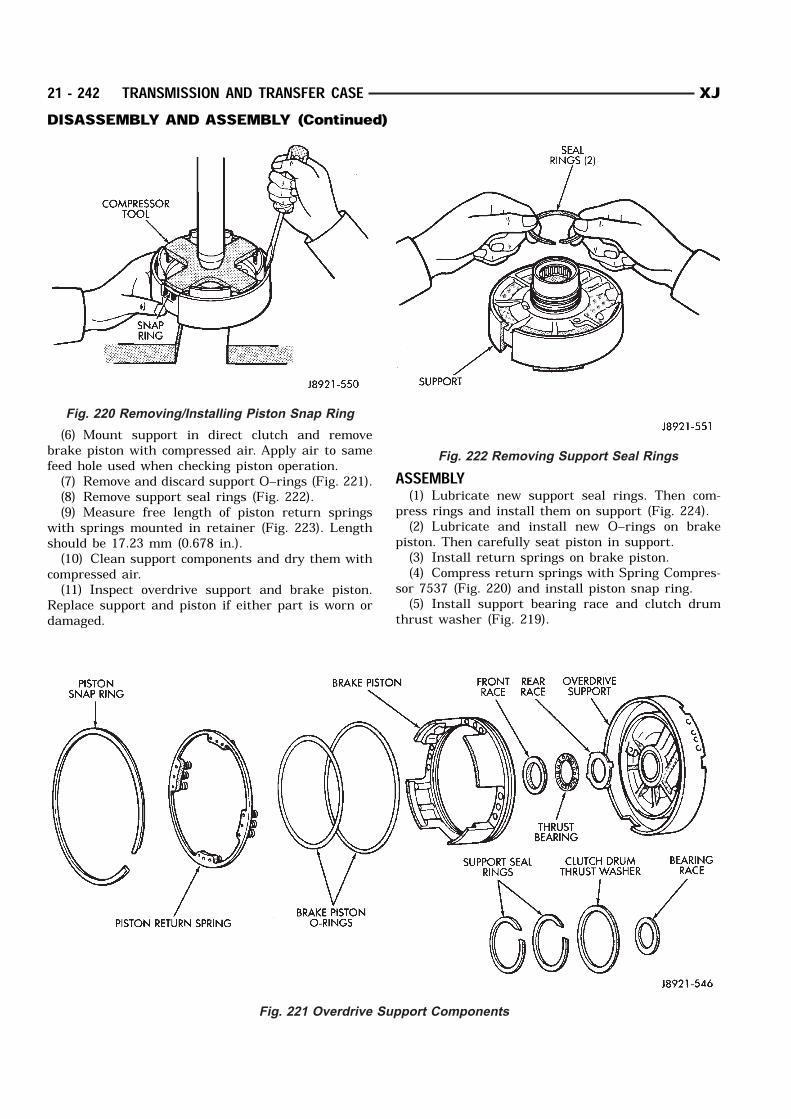
(6) Mount support in direct clutch and removebrake piston with compressed air. Apply air to samefeed hole used when checking piston operation.(7) Remove and discard support O–rings (Fig. 221).(8) Remove support seal rings (Fig. 222).(9) Measure free length of piston return springs
with springs mounted in retainer (Fig. 223). Lengthshould be 17.23 mm (0.678 in.).(10) Clean support components and dry them with
compressed air.(11) Inspect overdrive support and brake piston.
Replace support and piston if either part is worn ordamaged.
ASSEMBLY(1) Lubricate new support seal rings. Then com-
press rings and install them on support (Fig. 224).(2) Lubricate and install new O–rings on brake
piston. Then carefully seat piston in support.(3) Install return springs on brake piston.(4) Compress return springs with Spring Compres-
sor 7537 (Fig. 220) and install piston snap ring.(5) Install support bearing race and clutch drum
thrust washer (Fig. 219).
Fig. 220 Removing/Installing Piston Snap Ring
Fig. 221 Overdrive Support Components
Fig. 222 Removing Support Seal Rings
21 - 242 TRANSMISSION AND TRANSFER CASE XJDISASSEMBLY AND ASSEMBLY (Continued)

(6) Install thrust bearing and front and rear bear-ing races. Thrust bearing rollers should face upwardas shown (Fig. 224).(7) Verify thrust bearing/race sizes (Fig. 225). Front race outer diameter is 47.8 mm (1.882 in.)
and inside diameter is 30.7 mm (1.209 in.). Rear race outer diameter is 47.8 mm (1.882 in.)
and inside diameter is 34.3 mm (1.350 in.). Bearing outer diameter is 47.7 mm (1.878 in.)
and inside diameter is 32.7 mm (1.287 in.).
(8) Verify brake piston operation. Use same proce-dure described at beginning of disassembly. Pistonshould operate smoothly and not bind or stick.DIRECT CLUTCHDISASSEMBLY(1) Remove direct clutch from forward clutch (Fig.
226).
(2) Remove clutch drum thrust washer (Fig. 227).
Fig. 223 Checking Piston Return Spring Length
Fig. 224 Installing Support Seal Rings
Fig. 225 Installing Support Thrust Bearing And
Races
Fig. 226 Separate Direct Clutch From Forward
Clutch
XJ TRANSMISSION AND TRANSFER CASE 21 - 243DISASSEMBLY AND ASSEMBLY (Continued)

(3) Check clutch piston stroke length as outlinedin following steps.(4) Mount direct clutch on overdrive support
assembly (Fig. 228).
(5) Mount dial indicator on clutch and positionindicator plunger on clutch piston (Fig. 229).(6) Apply 57–114 psi air pressure through feed
hole in overdrive support and note piston strokelength (Fig. 229). Check stroke at least twice.(7) Piston stroke length should be 1.37 mm – 1.67
mm (0.054 – 0.065 in.). If stroke length is incorrect,
either the clutch pack retainer or clutch discs willhave to be replaced.(8) Remove clutch pack snap ring and remove
retainer and clutch pack from drum (Fig. 230).
(9) Compress clutch piston return springs with tool7538 and remove clutch piston snap ring (Fig. 231).(10) Remove compressor tool and return spring.(11) Remove clutch piston. Remount clutch on
overdrive support (Fig. 232). Apply compressed air
Fig. 227 Removing Clutch Drum Thrust Washer
Fig. 228 Mount Direct Clutch On Overdrive Support
Fig. 229 Checking Direct Clutch Piston Stroke
Length
Fig. 230 Removing Clutch Pack Snap Ring
21 - 244 TRANSMISSION AND TRANSFER CASE XJDISASSEMBLY AND ASSEMBLY (Continued)
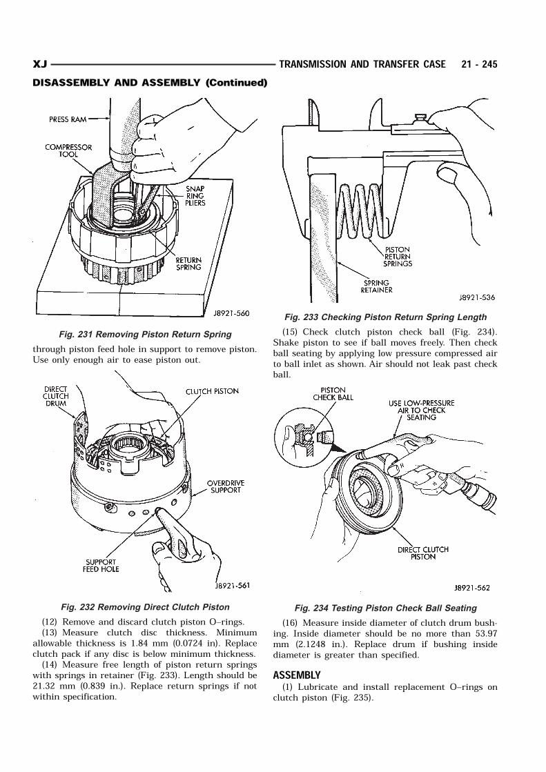
through piston feed hole in support to remove piston.Use only enough air to ease piston out.
(12) Remove and discard clutch piston O–rings.(13) Measure clutch disc thickness. Minimum
allowable thickness is 1.84 mm (0.0724 in). Replaceclutch pack if any disc is below minimum thickness.(14) Measure free length of piston return springs
with springs in retainer (Fig. 233). Length should be21.32 mm (0.839 in.). Replace return springs if notwithin specification.
(15) Check clutch piston check ball (Fig. 234).Shake piston to see if ball moves freely. Then checkball seating by applying low pressure compressed airto ball inlet as shown. Air should not leak past checkball.
(16) Measure inside diameter of clutch drum bush-ing. Inside diameter should be no more than 53.97mm (2.1248 in.). Replace drum if bushing insidediameter is greater than specified.ASSEMBLY(1) Lubricate and install replacement O–rings on
clutch piston (Fig. 235).
Fig. 231 Removing Piston Return Spring
Fig. 232 Removing Direct Clutch Piston
Fig. 233 Checking Piston Return Spring Length
Fig. 234 Testing Piston Check Ball Seating
XJ TRANSMISSION AND TRANSFER CASE 21 - 245DISASSEMBLY AND ASSEMBLY (Continued)
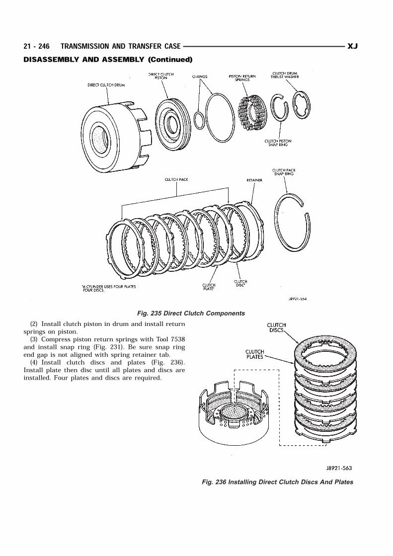
(2) Install clutch piston in drum and install returnsprings on piston.(3) Compress piston return springs with Tool 7538
and install snap ring (Fig. 231). Be sure snap ringend gap is not aligned with spring retainer tab.(4) Install clutch discs and plates (Fig. 236).
Install plate then disc until all plates and discs areinstalled. Four plates and discs are required.
Fig. 235 Direct Clutch Components
Fig. 236 Installing Direct Clutch Discs And Plates
21 - 246 TRANSMISSION AND TRANSFER CASE XJDISASSEMBLY AND ASSEMBLY (Continued)
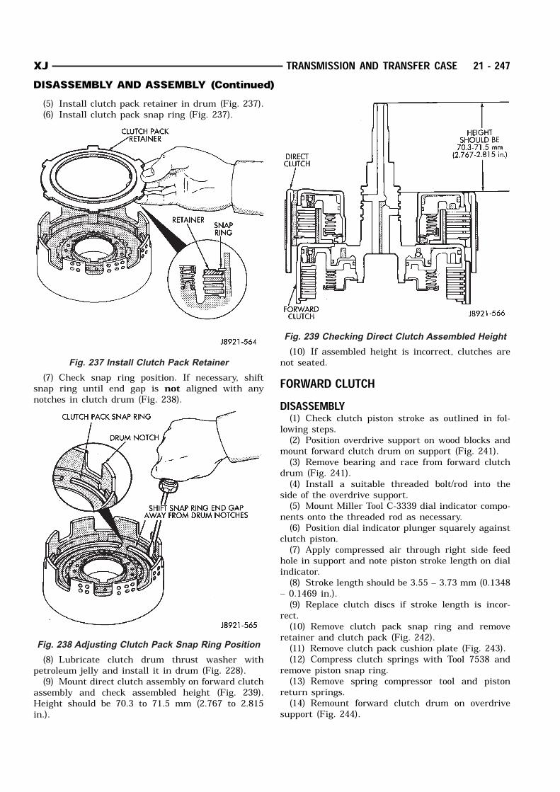
(5) Install clutch pack retainer in drum (Fig. 237).(6) Install clutch pack snap ring (Fig. 237).
(7) Check snap ring position. If necessary, shiftsnap ring until end gap is not aligned with anynotches in clutch drum (Fig. 238).
(8) Lubricate clutch drum thrust washer withpetroleum jelly and install it in drum (Fig. 228).(9) Mount direct clutch assembly on forward clutch
assembly and check assembled height (Fig. 239).Height should be 70.3 to 71.5 mm (2.767 to 2.815in.).
(10) If assembled height is incorrect, clutches arenot seated.FORWARD CLUTCHDISASSEMBLY(1) Check clutch piston stroke as outlined in fol-
lowing steps.(2) Position overdrive support on wood blocks and
mount forward clutch drum on support (Fig. 241).(3) Remove bearing and race from forward clutch
drum (Fig. 241).(4) Install a suitable threaded bolt/rod into the
side of the overdrive support.(5) Mount Miller Tool C-3339 dial indicator compo-
nents onto the threaded rod as necessary.(6) Position dial indicator plunger squarely against
clutch piston.(7) Apply compressed air through right side feed
hole in support and note piston stroke length on dialindicator.(8) Stroke length should be 3.55 – 3.73 mm (0.1348
– 0.1469 in.).(9) Replace clutch discs if stroke length is incor-
rect.(10) Remove clutch pack snap ring and remove
retainer and clutch pack (Fig. 242).(11) Remove clutch pack cushion plate (Fig. 243).(12) Compress clutch springs with Tool 7538 and
remove piston snap ring.(13) Remove spring compressor tool and piston
return springs.(14) Remount forward clutch drum on overdrive
support (Fig. 244).
Fig. 237 Install Clutch Pack Retainer
Fig. 238 Adjusting Clutch Pack Snap Ring Position
Fig. 239 Checking Direct Clutch Assembled Height
XJ TRANSMISSION AND TRANSFER CASE 21 - 247DISASSEMBLY AND ASSEMBLY (Continued)
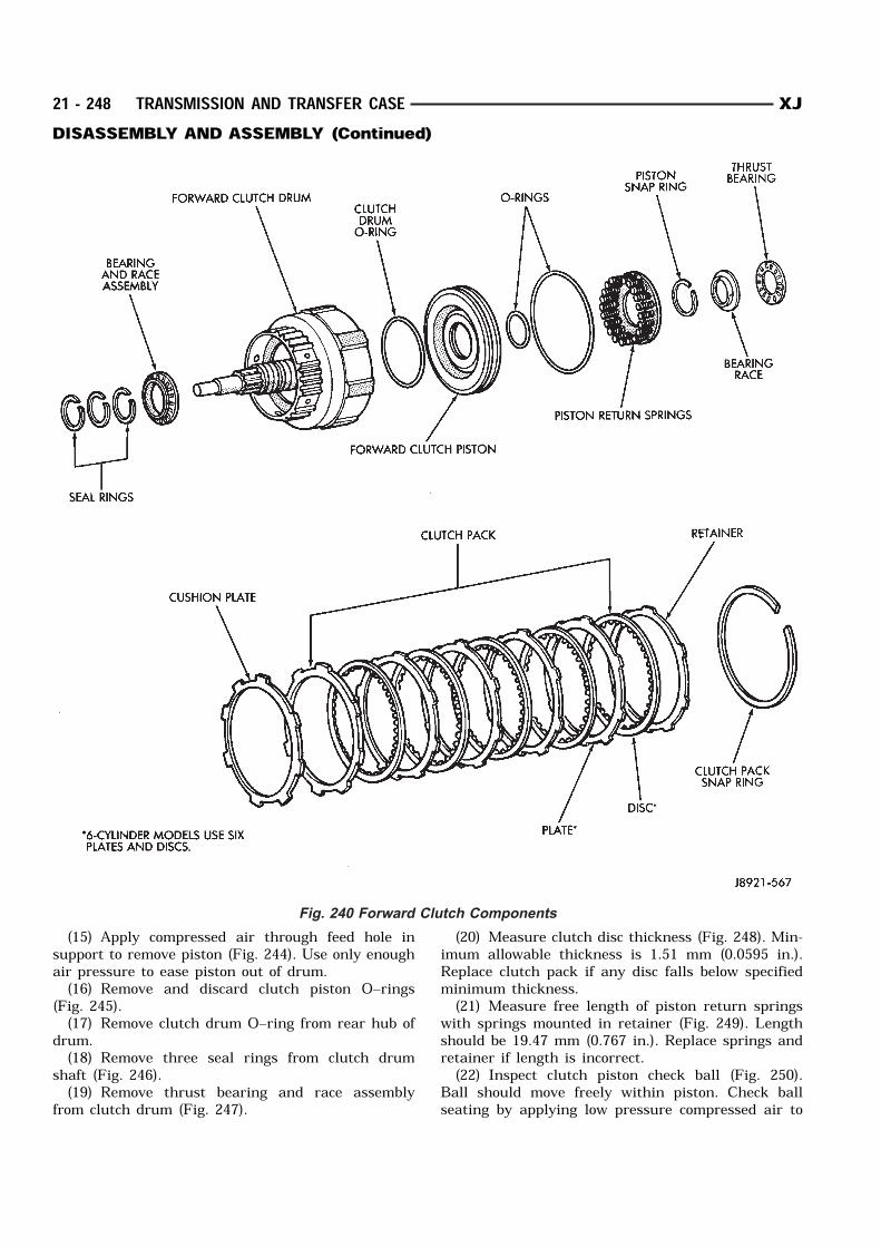
(15) Apply compressed air through feed hole insupport to remove piston (Fig. 244). Use only enoughair pressure to ease piston out of drum.(16) Remove and discard clutch piston O–rings
(Fig. 245).(17) Remove clutch drum O–ring from rear hub of
drum.(18) Remove three seal rings from clutch drum
shaft (Fig. 246).(19) Remove thrust bearing and race assembly
from clutch drum (Fig. 247).
(20) Measure clutch disc thickness (Fig. 248). Min-imum allowable thickness is 1.51 mm (0.0595 in.).Replace clutch pack if any disc falls below specifiedminimum thickness.(21) Measure free length of piston return springs
with springs mounted in retainer (Fig. 249). Lengthshould be 19.47 mm (0.767 in.). Replace springs andretainer if length is incorrect.(22) Inspect clutch piston check ball (Fig. 250).
Ball should move freely within piston. Check ballseating by applying low pressure compressed air to
Fig. 240 Forward Clutch Components
21 - 248 TRANSMISSION AND TRANSFER CASE XJDISASSEMBLY AND ASSEMBLY (Continued)
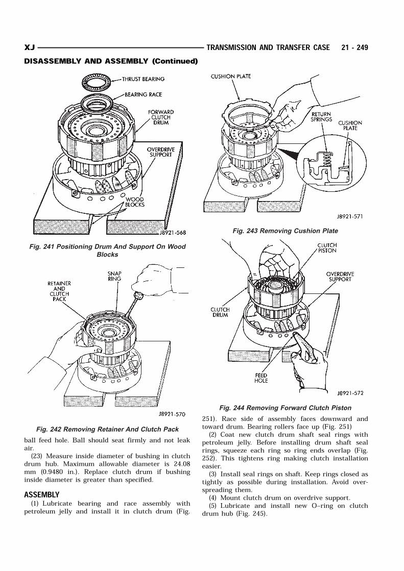
ball feed hole. Ball should seat firmly and not leakair.(23) Measure inside diameter of bushing in clutch
drum hub. Maximum allowable diameter is 24.08mm (0.9480 in.). Replace clutch drum if bushinginside diameter is greater than specified.ASSEMBLY(1) Lubricate bearing and race assembly with
petroleum jelly and install it in clutch drum (Fig.
251). Race side of assembly faces downward andtoward drum. Bearing rollers face up (Fig. 251)(2) Coat new clutch drum shaft seal rings with
petroleum jelly. Before installing drum shaft sealrings, squeeze each ring so ring ends overlap (Fig.252). This tightens ring making clutch installationeasier.(3) Install seal rings on shaft. Keep rings closed as
tightly as possible during installation. Avoid over-spreading them.(4) Mount clutch drum on overdrive support.(5) Lubricate and install new O–ring on clutch
drum hub (Fig. 245).
Fig. 241 Positioning Drum And Support On Wood
Blocks
Fig. 242 Removing Retainer And Clutch Pack
Fig. 243 Removing Cushion Plate
Fig. 244 Removing Forward Clutch Piston
XJ TRANSMISSION AND TRANSFER CASE 21 - 249DISASSEMBLY AND ASSEMBLY (Continued)

(6) Lubricate new clutch piston O–rings withMopar Door Ease, or Ru–Glyde. Install rings onclutch piston and install piston in drum.(7) Install piston return springs.(8) Compress piston return springs with Tool 7538
and shop press and install piston snap ring. Be suresnap ring end gap is not aligned with any notches indrum.(9) Install cushion plate in drum. Concave side of
plate faces downward (Fig. 243).(10) Install clutch discs, plates and retainer (Fig.
253). Install tabbed plate followed by disc until
required number of plates and discs are installed.Use six plates and discs.(11) Install clutch pack snap ring.(12) Recheck clutch piston stroke length using
same method outlined at beginning of disassemblyprocedure. If stroke length is not within specifiedlimits, replace clutch discs.(13) Lubricate race and bearing with petroleum
jelly and install them in clutch drum (Fig. 254). Be
Fig. 245 Removing/Installing Clutch Drum O–Ring
Fig. 246 Removing Clutch Drum Seal Rings
Fig. 247 Removing Clutch Drum Thrust Bearing
Assembly
Fig. 248 Measuring Clutch Disc Thickness
21 - 250 TRANSMISSION AND TRANSFER CASE XJDISASSEMBLY AND ASSEMBLY (Continued)
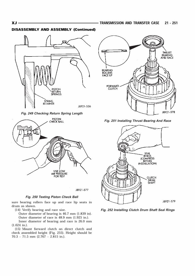
sure bearing rollers face up and race lip seats indrum as shown.(14) Verify bearing and race size. Outer diameter of bearing is 46.7 mm (1.839 in). Outer diameter of race is 48.9 mm (1.925 in.). Inner diameter of bearing and race is 26.0 mm
(1.024 in.).(15) Mount forward clutch on direct clutch and
check assembled height (Fig. 255). Height should be70.3 – 71.5 mm (2.767 – 2.815 in.).
Fig. 249 Checking Return Spring Length
Fig. 250 Testing Piston Check Ball
Fig. 251 Installing Thrust Bearing And Race
Fig. 252 Installing Clutch Drum Shaft Seal Rings
XJ TRANSMISSION AND TRANSFER CASE 21 - 251DISASSEMBLY AND ASSEMBLY (Continued)
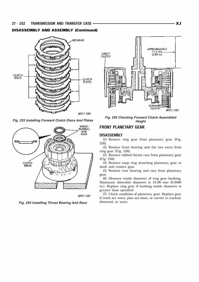
FRONT PLANETARY GEARDISASSEMBLY(1) Remove ring gear from planetary gear (Fig.
256).(2) Remove front bearing and the two races from
ring gear (Fig. 256).(3) Remove tabbed thrust race from planetary gear
(Fig. 256).(4) Remove snap ring attaching planetary gear to
shaft and remove gear.(5) Remove rear bearing and race from planetary
gear.(6) Measure inside diameter of ring gear bushing.
Maximum allowable diameter is 24.08 mm (0.9480in.). Replace ring gear if bushing inside diameter isgreater than specified.(7) Check condition of planetary gear. Replace gear
if teeth are worn, pins are loose, or carrier is cracked,distorted, or worn.
Fig. 253 Installing Forward Clutch Discs And Plates
Fig. 254 Installing Thrust Bearing And Race
Fig. 255 Checking Forward Clutch Assembled
Height
21 - 252 TRANSMISSION AND TRANSFER CASE XJDISASSEMBLY AND ASSEMBLY (Continued)
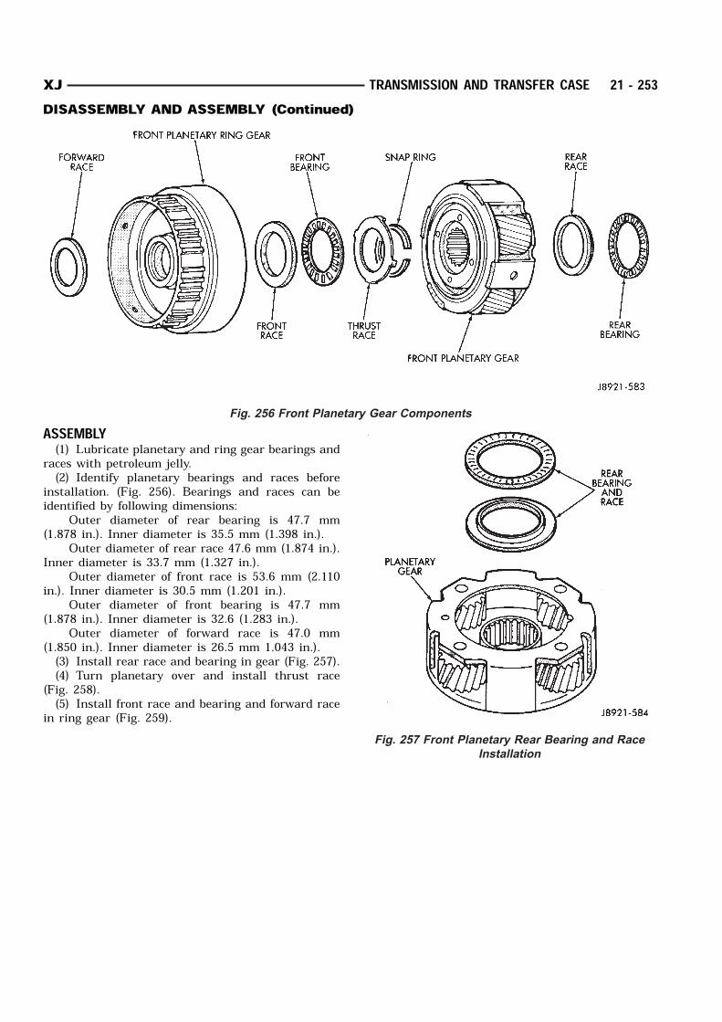
ASSEMBLY(1) Lubricate planetary and ring gear bearings and
races with petroleum jelly.(2) Identify planetary bearings and races before
installation. (Fig. 256). Bearings and races can beidentified by following dimensions:
Outer diameter of rear bearing is 47.7 mm(1.878 in.). Inner diameter is 35.5 mm (1.398 in.).
Outer diameter of rear race 47.6 mm (1.874 in.).Inner diameter is 33.7 mm (1.327 in.).
Outer diameter of front race is 53.6 mm (2.110in.). Inner diameter is 30.5 mm (1.201 in.).
Outer diameter of front bearing is 47.7 mm(1.878 in.). Inner diameter is 32.6 (1.283 in.).
Outer diameter of forward race is 47.0 mm(1.850 in.). Inner diameter is 26.5 mm 1.043 in.).(3) Install rear race and bearing in gear (Fig. 257).(4) Turn planetary over and install thrust race
(Fig. 258).(5) Install front race and bearing and forward race
in ring gear (Fig. 259).
Fig. 256 Front Planetary Gear Components
Fig. 257 Front Planetary Rear Bearing and Race
Installation
XJ TRANSMISSION AND TRANSFER CASE 21 - 253DISASSEMBLY AND ASSEMBLY (Continued)

SUN GEAR AND NO. 1 ONE–WAY CLUTCHFig. 259 Front Planetary Front Bearing And Races
Installation
Fig. 258 Front Planetary Thrust Race Installation
Sun Gear And One–Way Clutch Components
21 - 254 TRANSMISSION AND TRANSFER CASE XJDISASSEMBLY AND ASSEMBLY (Continued)
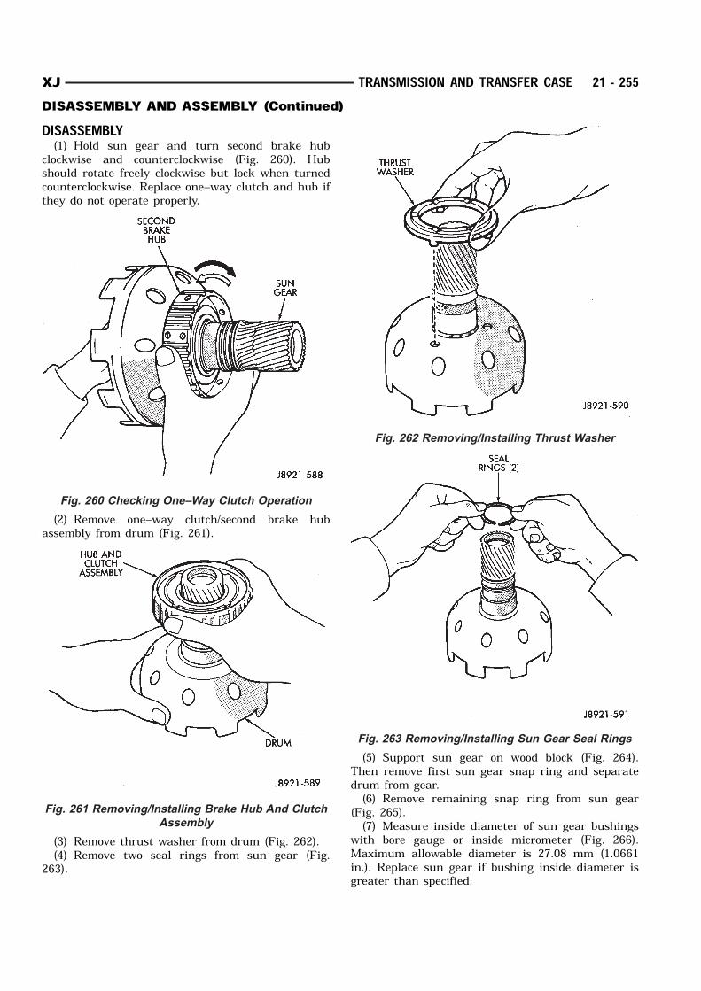
DISASSEMBLY(1) Hold sun gear and turn second brake hub
clockwise and counterclockwise (Fig. 260). Hubshould rotate freely clockwise but lock when turnedcounterclockwise. Replace one–way clutch and hub ifthey do not operate properly.
(2) Remove one–way clutch/second brake hubassembly from drum (Fig. 261).
(3) Remove thrust washer from drum (Fig. 262).(4) Remove two seal rings from sun gear (Fig.
263).
(5) Support sun gear on wood block (Fig. 264).Then remove first sun gear snap ring and separatedrum from gear.(6) Remove remaining snap ring from sun gear
(Fig. 265).(7) Measure inside diameter of sun gear bushings
with bore gauge or inside micrometer (Fig. 266).Maximum allowable diameter is 27.08 mm (1.0661in.). Replace sun gear if bushing inside diameter isgreater than specified.
Fig. 260 Checking One–Way Clutch Operation
Fig. 261 Removing/Installing Brake Hub And Clutch
Assembly
Fig. 262 Removing/Installing Thrust Washer
Fig. 263 Removing/Installing Sun Gear Seal Rings
XJ TRANSMISSION AND TRANSFER CASE 21 - 255DISASSEMBLY AND ASSEMBLY (Continued)
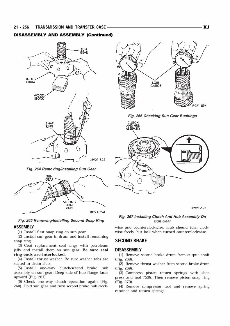
ASSEMBLY(1) Install first snap ring on sun gear.(2) Install sun gear in drum and install remaining
snap ring.(3) Coat replacement seal rings with petroleum
jelly and install them on sun gear. Be sure sealring ends are interlocked.(4) Install thrust washer. Be sure washer tabs are
seated in drum slots.(5) Install one–way clutch/second brake hub
assembly on sun gear. Deep side of hub flange facesupward (Fig. 267).(6) Check one–way clutch operation again (Fig.
260). Hold sun gear and turn second brake hub clock-
wise and counterclockwise. Hub should turn clock-wise freely, but lock when turned counterclockwise.SECOND BRAKEDISASSEMBLY(1) Remove second brake drum from output shaft
(Fig. 268).(2) Remove thrust washer from second brake drum
(Fig. 269).(3) Compress piston return springs with shop
press and tool 7538. Then remove piston snap ring(Fig. 270).(4) Remove compressor tool and remove spring
retainer and return springs.
Fig. 264 Removing/Installing Sun Gear
Fig. 265 Removing/Installing Second Snap Ring
Fig. 266 Checking Sun Gear Bushings
Fig. 267 Installing Clutch And Hub Assembly On
Sun Gear
21 - 256 TRANSMISSION AND TRANSFER CASE XJDISASSEMBLY AND ASSEMBLY (Continued)
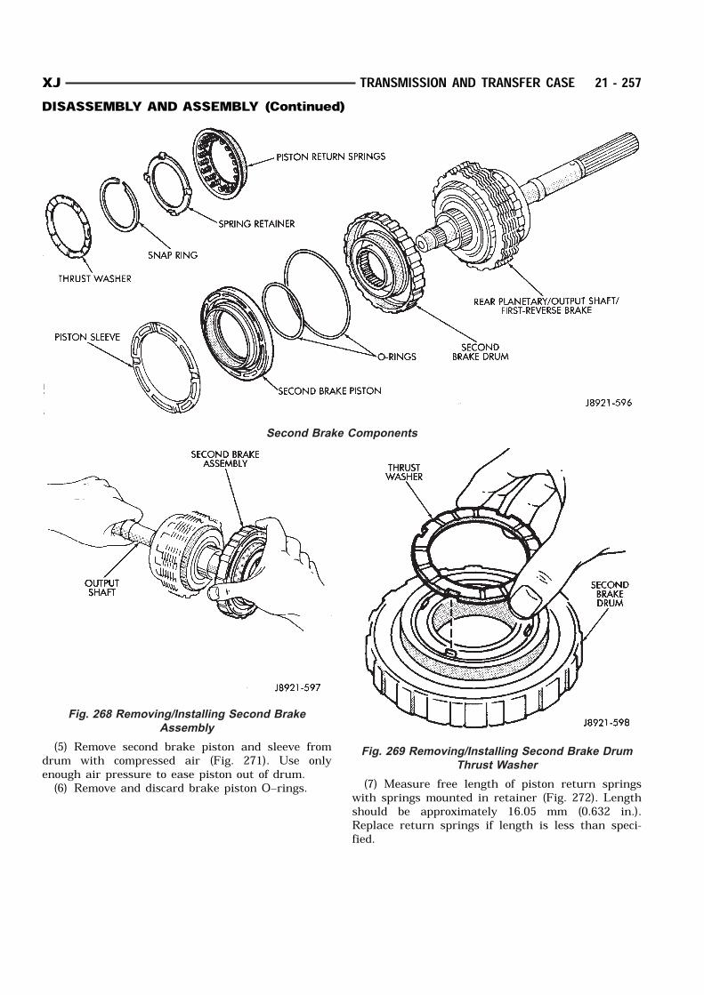
(5) Remove second brake piston and sleeve fromdrum with compressed air (Fig. 271). Use onlyenough air pressure to ease piston out of drum.(6) Remove and discard brake piston O–rings. (7) Measure free length of piston return springs
with springs mounted in retainer (Fig. 272). Lengthshould be approximately 16.05 mm (0.632 in.).Replace return springs if length is less than speci-fied.
Second Brake Components
Fig. 268 Removing/Installing Second Brake
Assembly
Fig. 269 Removing/Installing Second Brake Drum
Thrust Washer
XJ TRANSMISSION AND TRANSFER CASE 21 - 257DISASSEMBLY AND ASSEMBLY (Continued)
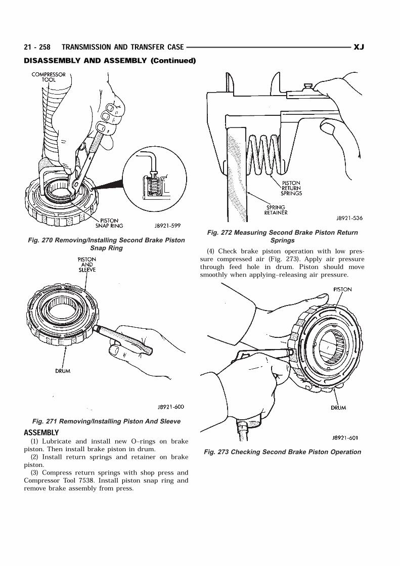
ASSEMBLY(1) Lubricate and install new O–rings on brake
piston. Then install brake piston in drum.(2) Install return springs and retainer on brake
piston.(3) Compress return springs with shop press and
Compressor Tool 7538. Install piston snap ring andremove brake assembly from press.
(4) Check brake piston operation with low pres-sure compressed air (Fig. 273). Apply air pressurethrough feed hole in drum. Piston should movesmoothly when applying–releasing air pressure.
Fig. 270 Removing/Installing Second Brake Piston
Snap Ring
Fig. 271 Removing/Installing Piston And Sleeve
Fig. 272 Measuring Second Brake Piston Return
Springs
Fig. 273 Checking Second Brake Piston Operation
21 - 258 TRANSMISSION AND TRANSFER CASE XJDISASSEMBLY AND ASSEMBLY (Continued)
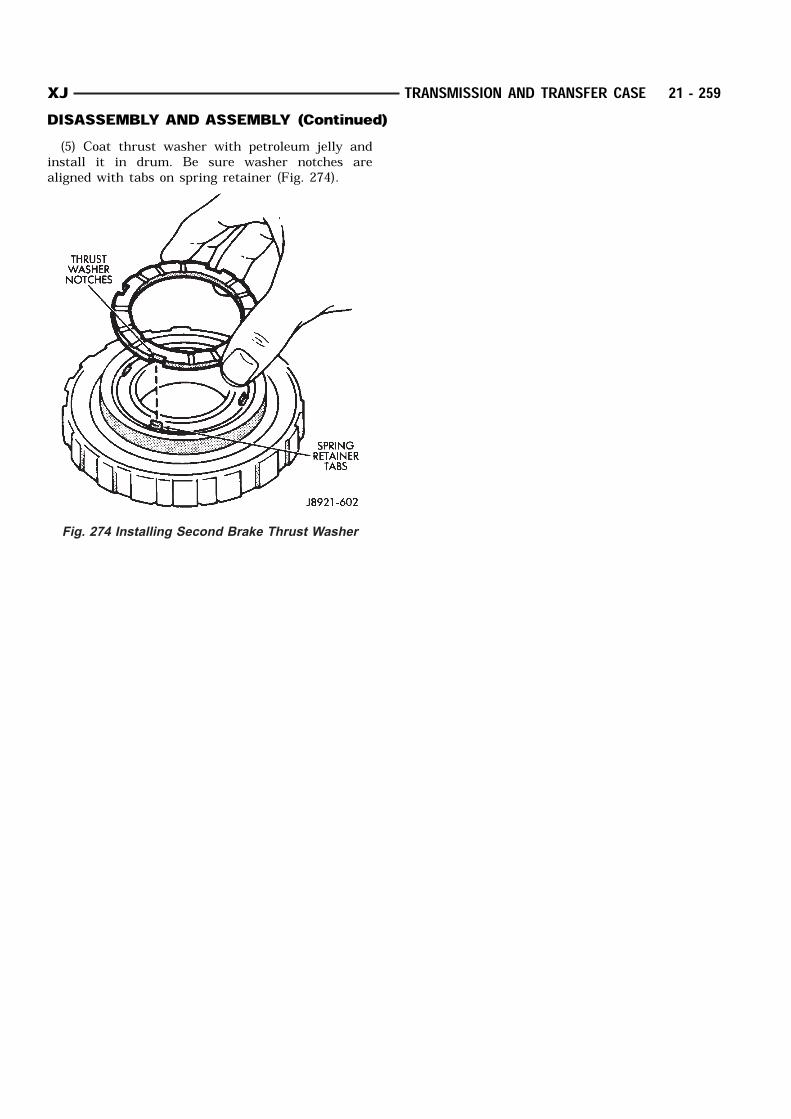
(5) Coat thrust washer with petroleum jelly andinstall it in drum. Be sure washer notches arealigned with tabs on spring retainer (Fig. 274).
Fig. 274 Installing Second Brake Thrust Washer
XJ TRANSMISSION AND TRANSFER CASE 21 - 259DISASSEMBLY AND ASSEMBLY (Continued)
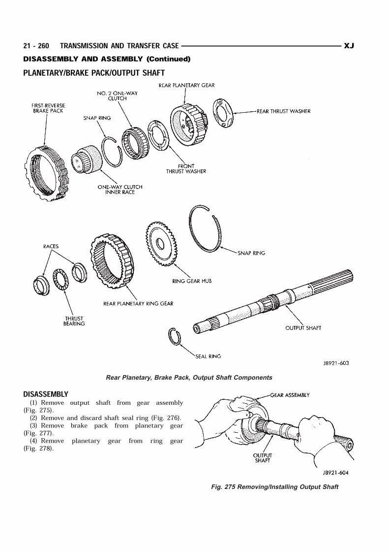
PLANETARY/BRAKE PACK/OUTPUT SHAFT
DISASSEMBLY(1) Remove output shaft from gear assembly
(Fig. 275).(2) Remove and discard shaft seal ring (Fig. 276).(3) Remove brake pack from planetary gear
(Fig. 277).(4) Remove planetary gear from ring gear
(Fig. 278).
Rear Planetary, Brake Pack, Output Shaft Components
Fig. 275 Removing/Installing Output Shaft
21 - 260 TRANSMISSION AND TRANSFER CASE XJDISASSEMBLY AND ASSEMBLY (Continued)
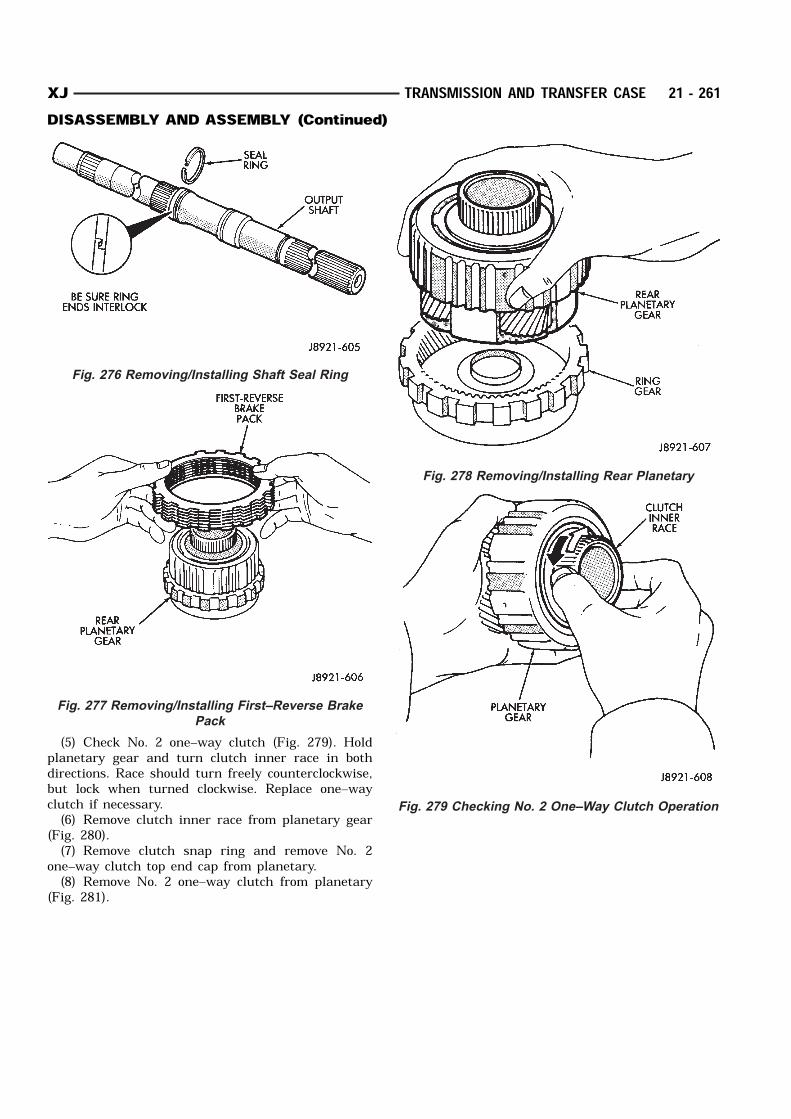
(5) Check No. 2 one–way clutch (Fig. 279). Holdplanetary gear and turn clutch inner race in bothdirections. Race should turn freely counterclockwise,but lock when turned clockwise. Replace one–wayclutch if necessary.(6) Remove clutch inner race from planetary gear
(Fig. 280).(7) Remove clutch snap ring and remove No. 2
one–way clutch top end cap from planetary.(8) Remove No. 2 one–way clutch from planetary
(Fig. 281).
Fig. 276 Removing/Installing Shaft Seal Ring
Fig. 277 Removing/Installing First–Reverse Brake
Pack
Fig. 278 Removing/Installing Rear Planetary
Fig. 279 Checking No. 2 One–Way Clutch Operation
XJ TRANSMISSION AND TRANSFER CASE 21 - 261DISASSEMBLY AND ASSEMBLY (Continued)
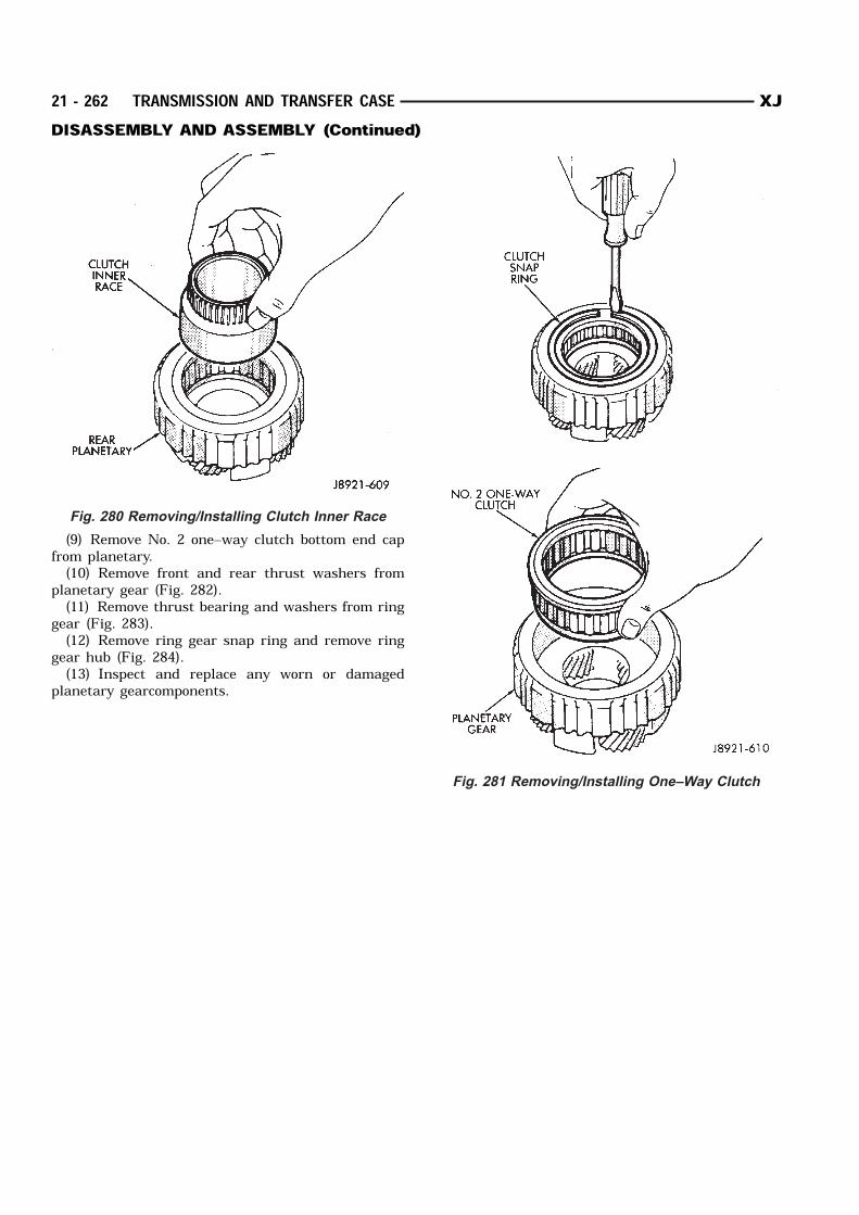
(9) Remove No. 2 one–way clutch bottom end capfrom planetary.(10) Remove front and rear thrust washers from
planetary gear (Fig. 282).(11) Remove thrust bearing and washers from ring
gear (Fig. 283).(12) Remove ring gear snap ring and remove ring
gear hub (Fig. 284).(13) Inspect and replace any worn or damaged
planetary gearcomponents.
Fig. 280 Removing/Installing Clutch Inner Race
Fig. 281 Removing/Installing One–Way Clutch
21 - 262 TRANSMISSION AND TRANSFER CASE XJDISASSEMBLY AND ASSEMBLY (Continued)
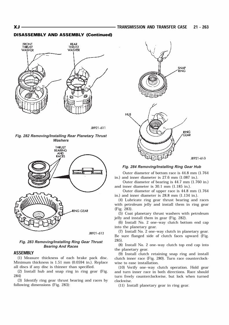
ASSEMBLY(1) Measure thickness of each brake pack disc.
Minimum thickness is 1.51 mm (0.0594 in.). Replaceall discs if any disc is thinner than specified.(2) Install hub and snap ring in ring gear (Fig.
284)(3) Identify ring gear thrust bearing and races by
following dimensions (Fig. 283):
Outer diameter of bottom race is 44.8 mm (1.764in.) and inner diameter is 27.6 mm (1.087 in.).
Outer diameter of bearing is 44.7 mm (1.760 in.)and inner diameter is 30.1 mm (1.185 in.).
Outer diameter of upper race is 44.8 mm (1.764in.) and inner diameter is 28.8 mm (1.134 in.).(4) Lubricate ring gear thrust bearing and races
with petroleum jelly and install them in ring gear(Fig. 283).(5) Coat planetary thrust washers with petroleum
jelly and install them in gear (Fig. 282).(6) Install No. 2 one–way clutch bottom end cap
into the planetary gear.(7) Install No. 2 one–way clutch in planetary gear.
Be sure flanged side of clutch faces upward (Fig.285).(8) Install No. 2 one–way clutch top end cap into
the planetary gear.(9) Install clutch retaining snap ring and install
clutch inner race (Fig. 280). Turn race counterclock-wise to ease installation.(10) Verify one–way clutch operation. Hold gear
and turn inner race in both directions. Race shouldturn freely counterclockwise, but lock when turnedclockwise.(11) Install planetary gear in ring gear.
Fig. 282 Removing/Installing Rear Planetary Thrust
Washers
Fig. 283 Removing/Installing Ring Gear Thrust
Bearing And Races
Fig. 284 Removing/Installing Ring Gear Hub
XJ TRANSMISSION AND TRANSFER CASE 21 - 263DISASSEMBLY AND ASSEMBLY (Continued)
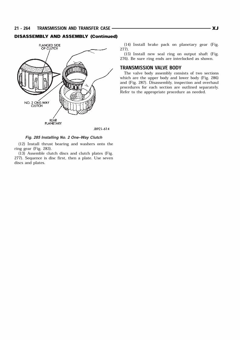
(12) Install thrust bearing and washers onto thering gear (Fig. 283).(13) Assemble clutch discs and clutch plates (Fig.
277). Sequence is disc first, then a plate. Use sevendiscs and plates.
(14) Install brake pack on planetary gear (Fig.277).(15) Install new seal ring on output shaft (Fig.
276). Be sure ring ends are interlocked as shown.TRANSMISSION VALVE BODYThe valve body assembly consists of two sections
which are the upper body and lower body (Fig. 286)and (Fig. 287). Disassembly, inspection and overhaulprocedures for each section are outlined separately.Refer to the appropriate procedure as needed.
Fig. 285 Installing No. 2 One–Way Clutch
21 - 264 TRANSMISSION AND TRANSFER CASE XJDISASSEMBLY AND ASSEMBLY (Continued)
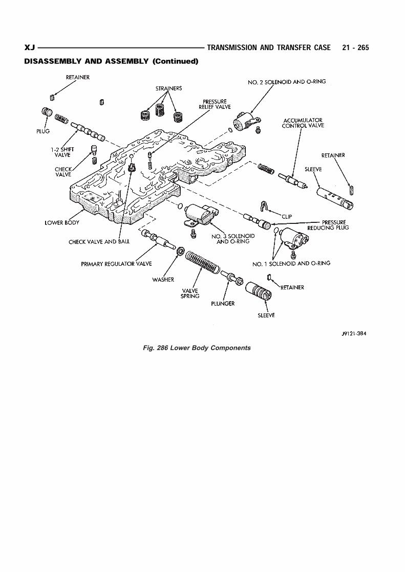
Fig. 286 Lower Body Components
XJ TRANSMISSION AND TRANSFER CASE 21 - 265DISASSEMBLY AND ASSEMBLY (Continued)

Fig. 287 Upper Body Components
21 - 266 TRANSMISSION AND TRANSFER CASE XJDISASSEMBLY AND ASSEMBLY (Continued)
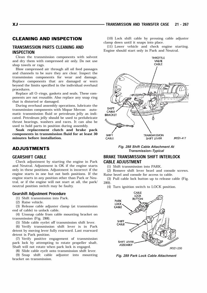
CLEANING AND INSPECTIONTRANSMISSION PARTS CLEANING ANDINSPECTIONClean the transmission components with solvent
and dry them with compressed air only. Do not useshop towels or rags.Blow compressed air through all oil feed passages
and channels to be sure they are clear. Inspect thetransmission components for wear and damage.Replace components that are damaged or wornbeyond the limits specified in the individual overhaulprocedures.Replace all O–rings, gaskets and seals. These com-
ponents are not reusable. Also replace any snap ringthat is distorted or damaged.During overhaul assembly operations, lubricate the
transmission components with Mopar Mercon auto-matic transmission fluid or petroleum jelly as indi-cated. Petroleum jelly should be used to prelubricatethrust bearings, washers and races. It can also beused to hold parts in position during assembly.Soak replacement clutch and brake pack
components in transmission fluid for at least 30minutes before installation.
ADJUSTMENTSGEARSHIFT CABLECheck adjustment by starting the engine in Park
and Neutral. Adjustment is OK if the engine startsonly in these positions. Adjustment is incorrect if theengine starts in one but not both positions. If theengine starts in any position other than Park or Neu-tral, or if the engine will not start at all, the park/neutral position switch may be faulty.Gearshift Adjustment Procedure(1) Shift transmission into Park.(2) Raise vehicle.(3) Release cable adjuster clamp (at transmission
end of cable) to unlock cable.(4) Unsnap cable from cable mounting bracket on
transmission (Fig. 288).(5) Slide cable eyelet off transmission shift lever.(6) Verify transmission shift lever is in Park
detent by moving lever fully rearward. Last rearwarddetent is Park position.(7) Verify positive engagement of transmission
park lock by attempting to rotate propeller shaft.Shaft will not rotate when park lock is engaged.(8) Slide cable eyelt onto transmission shift lever.(9) Snap shift cable adjuster into mounting
bracket on transmission.
(10) Lock shift cable by pressing cable adjusterclamp down until it snaps into place.(11) Lower vehicle and check engine starting.
Engine should start only in Park and Neutral.
BRAKE TRANSMISSION SHIFT INTERLOCKCABLE ADJUSTMENT(1) Shift transmission into PARK.(2) Remove shift lever bezel and console screws.
Raise bezel and console for access to cable.(3) Pull cable lock button up to release cable (Fig.
289).(4) Turn ignition switch to LOCK position.
Fig. 288 Shift Cable Attachment At
Transmission–Typical
Fig. 289 Park Lock Cable Attachment
XJ TRANSMISSION AND TRANSFER CASE 21 - 267

(5) Use a spacer to create a one millimeter gapbetween the shifter pawl and top of the shift gate.(6) Pull cable forward. Then release cable and
press cable lock button down until it snaps in place.(7) Check adjustment as follows:(a) Check movement of release shift handle but-
ton (floor shift) or release lever (column shift). Youshould not be able to press button inward or movecolumn lever.(b) Turn ignition switch to RUN position.(c) Shifting out of park should not be possible.(d) Apply the brake and attempt to shift out of
PARK. Shifting should be possible.(e) While the transmission is shifted out of
PARK, release the brake and attempt to shiftthrough all gears. Release the shift button at leastonce during this procedure. The ignition key shouldnot go to the LOCK position.(f) Return transmission to the PARK position
without applying the brake.(8) Move shift lever back to PARK and check igni-
tion switch operation. You should be able to turnswitch to LOCK position and shift lever release but-ton/lever should not move.TRANSMISSION THROTTLE VALVE CABLEADJUSTMENTThe transmission throttle valve is operated by a
cam on the throttle lever. The throttle lever is oper-ated by an adjustable cable (Fig. 290). The cable isattached to an arm mounted on the throttle levershaft. A retaining clip at the engine-end of the cableis removed to provide for cable adjustment. Theretaining clip is then installed back onto the throttlevalve cable to lock in the adjustment.A correctly adjusted throttle valve cable will cause
the throttle lever on the transmission to move simul-taneously with the throttle body lever from the idleposition. Proper adjustment will allow simultaneousmovement without causing the transmission throttlelever to either move ahead of, or lag behind the leveron the throttle body.Checking Throttle Valve Cable Adjustment(1) Turn ignition key to OFF position.(2) Remove air cleaner.(3) Verify that lever on throttle body is at curb idle
position. Then verify that transmission throttle lever(Fig. 291) is also at idle (fully forward) position.(4) Slide cable off attachment stud on throttle body
lever.(5) Compare position of cable end to attachment
stud on throttle body lever: Cable end and attachment stud should be
aligned (or centered on one another) to within 1 mm(0.039 in.) in either direction.
If cable end and attachment stud are misaligned(off center), cable will have to be adjusted asdescribed in Throttle Valve Cable Adjustment proce-dure.(6) Reconnect cable end to attachment stud. Then
with aid of a helper, observe movement of transmis-sion throttle lever and lever on throttle body.
If both levers move simultaneously from idle tohalf-throttle and back to idle position, adjustment iscorrect.
If transmission throttle lever moves ahead of, orlags behind throttle body lever, cable adjustment willbe necessary. Or, if throttle body lever preventstransmission lever from returning to closed position,cable adjustment will be necessary.Throttle Valve Cable Adjustment Procedure(1) Turn ignition switch to OFF position.(2) Remove air cleaner if necessary.(3) Disconnect cable end from attachment stud.
Carefully slide cable off stud. Do not pry or pullcable off.
Fig. 290 Throttle Cable Attachment At Engine
Fig. 291 Throttle Cable Attachment At Transmission
21 - 268 TRANSMISSION AND TRANSFER CASE XJADJUSTMENTS (Continued)
(4) Verify that transmission throttle lever is infully closed position. Then be sure lever on throttlebody is at curb idle position.(5) Insert a small screwdriver under edge of
retaining clip and remove retaining clip.(6) Center cable end on attachment stud to within
1 mm (0.039 in.).NOTE: Be sure that as the cable is pulled forward
and centered on the throttle lever stud, the cable
housing moves smoothly with the cable. Due to the
angle at which the cable housing enters the spring
housing, the cable housing may bind slightly and
create an incorrect adjustment.
(7) Install retaining clip onto cable housing.(8) Check cable adjustment. Verify transmission
throttle lever and lever on throttle body move simul-taneously.
SPECIFICATIONSAW-4 AUTOMATIC TRANSMISSION
XJ TRANSMISSION AND TRANSFER CASE 21 - 269ADJUSTMENTS (Continued)
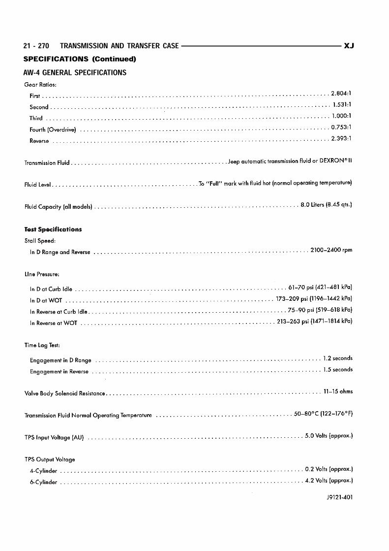
AW-4 GENERAL SPECIFICATIONS
21 - 270 TRANSMISSION AND TRANSFER CASE XJSPECIFICATIONS (Continued)
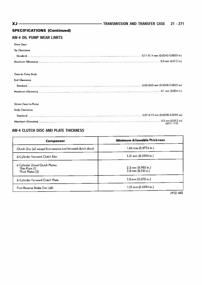
AW-4 OIL PUMP WEAR LIMITS
AW-4 CLUTCH DISC AND PLATE THICKNESS
XJ TRANSMISSION AND TRANSFER CASE 21 - 271SPECIFICATIONS (Continued)
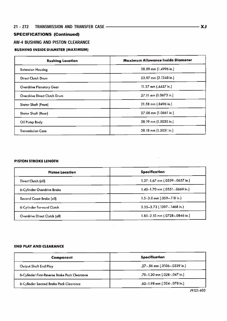
AW-4 BUSHING AND PISTON CLEARANCE
21 - 272 TRANSMISSION AND TRANSFER CASE XJSPECIFICATIONS (Continued)
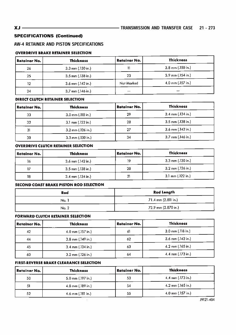
AW-4 RETAINER AND PISTON SPECIFICATIONS
XJ TRANSMISSION AND TRANSFER CASE 21 - 273SPECIFICATIONS (Continued)
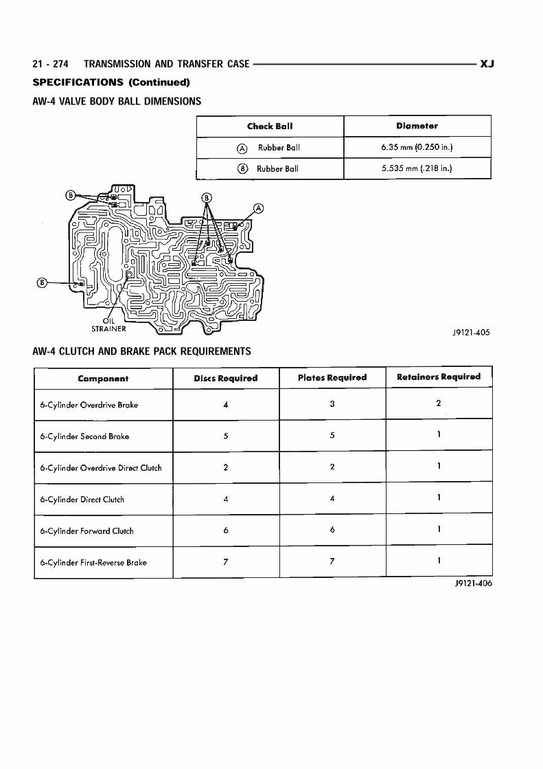
AW-4 VALVE BODY BALL DIMENSIONS
AW-4 CLUTCH AND BRAKE PACK REQUIREMENTS
21 - 274 TRANSMISSION AND TRANSFER CASE XJSPECIFICATIONS (Continued)
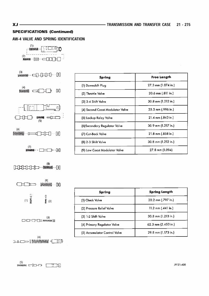
AW-4 VALVE AND SPRING IDENTIFICATION
XJ TRANSMISSION AND TRANSFER CASE 21 - 275SPECIFICATIONS (Continued)
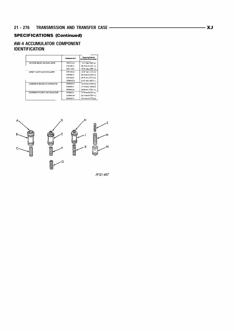
AW-4 ACCUMULATOR COMPONENTIDENTIFICATION
21 - 276 TRANSMISSION AND TRANSFER CASE XJSPECIFICATIONS (Continued)
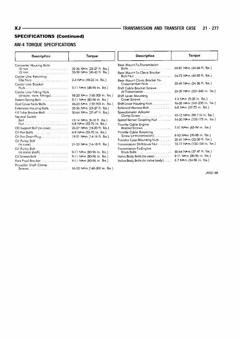
AW-4 TORQUE SPECIFICATIONS
XJ TRANSMISSION AND TRANSFER CASE 21 - 277SPECIFICATIONS (Continued)
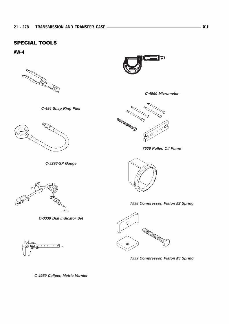
SPECIAL TOOLSAW-4
C-484 Snap Ring Plier
C-3293-SP Gauge
C-3339 Dial Indicator Set
C-4959 Caliper, Metric Vernier
C-4960 Micrometer
7536 Puller, Oil Pump
7538 Compressor, Piston #2 Spring
7539 Compressor, Piston #3 Spring
21 - 278 TRANSMISSION AND TRANSFER CASE XJ

7540 Pliers, Large Snap Ring
7542 Puller, Reaction Sleeve
7543 Puller, Piston #1
7544 Installer, Brake Drum Seal
7549 Installer, Seal
7552 Gauge, 3.0 mm Wire
7554 Adapter, Pressure Port
XJ TRANSMISSION AND TRANSFER CASE 21 - 279SPECIAL TOOLS (Continued)

NV231 TRANSFER CASEINDEX
page page
GENERAL INFORMATION
NV231 TRANSFER CASE . . . . . . . . . . . . . . . . . 280
RECOMMENDED LUBRICANT AND FILL
LEVEL . . . . . . . . . . . . . . . . . . . . . . . . . . . . . . 281
TRANSFER CASE IDENTIFICATION . . . . . . . . . 280
DIAGNOSIS AND TESTING
NV231 DIAGNOSIS . . . . . . . . . . . . . . . . . . . . . 281
REMOVAL AND INSTALLATION
FRONT OUTPUT SHAFT SEAL . . . . . . . . . . . . 283
SHIFT LEVER . . . . . . . . . . . . . . . . . . . . . . . . . . 282
SPEEDOMETER . . . . . . . . . . . . . . . . . . . . . . . . 282
TRANSFER CASE . . . . . . . . . . . . . . . . . . . . . . 282
DISASSEMBLY AND ASSEMBLY
NV231 TRANSFER CASE . . . . . . . . . . . . . . . . . 285
CLEANING AND INSPECTION
NV231 TRANSFER CASE . . . . . . . . . . . . . . . . . 299
ADJUSTMENTS
SHIFT LINKAGE ADJUSTMENT . . . . . . . . . . . . 303
SPECIFICATIONS
TORQUE . . . . . . . . . . . . . . . . . . . . . . . . . . . . . 303
SPECIAL TOOLS
NV231 . . . . . . . . . . . . . . . . . . . . . . . . . . . . . . . 303
GENERAL INFORMATIONNV231 TRANSFER CASEThe NV231 is a part-time transfer case with a low
range reduction gear system. The NV231 has threeoperating ranges plus a Neutral position. A low rangesystem provides a reduction ratio for increased lowspeed torque capability.The input gear is splined to the transmission out-
put shaft. The input gear drives the mainshaftthrough the planetary assembly and range hub. Thefront output shaft is operated by a drive chain thatconnects the shaft to a drive sprocket on the main-shaft. The drive sprocket is engaged/disengaged bythe mode fork, which operates the mode sleeve andhub. The sleeve and hub are not equipped with asynchronizer mechanism for shifting.The geartrain is mounted in two aluminum case
halves attached with bolts. The mainshaft front andrear bearings are mounted in aluminum retainerhousings bolted to the case halves.OPERATING RANGESTransfer case operating ranges are: 2WD (2-wheel drive) 4x4 (4-wheel drive) 4 Lo (4-wheel drive low rangeThe 2WD range is for use on any road surface at
any time.The 4x4 and 4 Lo ranges are for off road use only.
They are not for use on hard surface roads. The onlyexception being when the road surface is wet or slip-pery or covered by ice and snow.The low range reduction gear system is operative
in 4 Lo range only. This range is for extra pulling
power in off road situations. Low range reductionratio is 2.72:1.SHIFT MECHANISMOperating ranges are selected with a floor mounted
shift lever. The shift lever is connected to the trans-fer case range lever by an adjustable linkage rod. Astraight line shift pattern is used. Range positionsare marked on the shifter bezel cover plate.TRANSFER CASE IDENTIFICATIONA circular ID tag is attached to the rear case of
each transfer case (Fig. 1). The ID tag provides thetransfer case model number, assembly number, serialnumber, and low range ratio.The transfer case serial number also represents
the date of build.
Fig. 1 Fill/Drain Plug And I.D. Tag Locations
21 - 280 TRANSMISSION AND TRANSFER CASE XJ
RECOMMENDED LUBRICANT AND FILL LEVELRecommended lubricant for the NV231 transfer
case is Mopar Dexron II, or ATF Plus 3, type 7176.Approximate lubricant fill capacity is 1.2 liters (2.5pints).The fill and drain plugs are both in the rear case
(Fig. 1). Correct fill level is to the bottom edge of the
fill plug hole. Be sure the vehicle is level to ensurean accurate fluid level check.
DIAGNOSIS AND TESTINGNV231 DIAGNOSIS
DIAGNOSIS CHART
Condition Possible Cause Correction
Transfer case difficult to shift or will
not shift into desired range.
1) Vehicle speed to great to permit
shifting.
1) Slow vehicle and shift into
desired range.
2) If vehicle was operated for an
extended period in 4H mode on dry
surface, driveline torque load may
cause difficulty.
2) Stop vehicle and shift transfer
case to Neutral position. Transfer
case can then be shifted to the
desired mode.
3) Transfer case shift linkage
binding.
3) Repair or replace linkage as
necessary.
4) Insufficient or incorrect lubricant. 4) Drain and refill transfer case with
the correct type and quantity of
lubricant.
5) Internal transfer case
components binding, worn, or
damaged.
5) Repair or replace components as
necessary.
Transfer case noisy in all drive
modes.
1) Insufficient or incorrect lubricant. 1) Drain and refill transfer case with
the correct type and quantity of
lubricant.
Transfer case noisy while in, or
jumps out of, 4L mode.
1) Transfer case not completely
engaged in 4L position.
1) Slow vehicle, shift transfer case
to the Neutral position, and then
shift into the 4L mode.
2) Transfer case shift linkage out of
adjustment.
2) Adjust linkage as necessary.
3) Transfer case shift linkage loose
or binding.
3) Repair, replace, or tighten linkage
components as necessary.
4) Range fork damaged, inserts
worn, or fork is binding on the shift
rail.
4) Repair or replace components as
necessary.
5) Low range gear worn or
damaged.
5) Repair or replace components as
necessary.
Lubricant leaking from transfer case
seals or vent.
1) Transfer case overfilled. 1) Drain lubricant to the correct
level.
2) Transfer case vent closed or
restricted.
2) Clean or replace vent as
necessary.
3) Transfer case seals damaged or
installed incorrectly.
3) Replace suspect seal.
Abnormal tire wear. 1) Extended operation in 4H mode
on dry surfaces,
1) Operate vehicle in 2H mode on
dry surfaces.
XJ TRANSMISSION AND TRANSFER CASE 21 - 281GENERAL INFORMATION (Continued)

REMOVAL AND INSTALLATIONTRANSFER CASEREMOVAL(1) Shift transfer case into Neutral.(2) Raise vehicle.(3) Drain transfer case lubricant.(4) Mark front and rear propeller shaft yokes for
alignment reference.(5) Support transmission with jack stand.(6) Remove rear crossmember, or skid plate.(7) Disconnect front/rear propeller shafts at trans-
fer case.(8) Disconnect vehicle speed sensor wires.(9) Disconnect transfer case linkage rod from
range lever.(10) Disconnect transfer case vent hose (Fig. 2)
and indicator switch harness, if necessary.(11) Support transfer case with transmission jack.(12) Secure transfer case to jack with chains.(13) Remove nuts attaching transfer case to trans-
mission.(14) Pull transfer case and jack rearward to disen-
gage transfer case.(15) Remove transfer case from under vehicle.
INSTALLATION(1) Mount transfer case on a transmission jack.(2) Secure transfer case to jack with chains.(3) Position transfer case under vehicle.(4) Align transfer case and transmission shafts
and install transfer case on transmission.(5) Install and tighten transfer case attaching nuts
to 35 N·m (26 ft. lbs.) torque (Fig. 2).(6) Connect vehicle speed sensor wires, and vent
hose.
(7) Connect indicator switch harness to transfercase switch, if necessary. Secure wire harness to clipson transfer case.(8) Align and connect propeller shafts. Refer to
Group 3, Differential and Driveline, for proper proce-dures and specifications.(9) Fill transfer case with correct fluid. Check
transmission fluid level. Correct as necessary.(10) Install rear crossmember, or skid plate.
Tighten crossmember bolts to 41 N·m (30 ft. lbs.)torque.(11) Remove transmission jack and support stand.(12) Connect shift rod to transfer case range lever.(13) Adjust transfer case shift linkage.(14) Lower vehicle and verify transfer case shift
operation.SHIFT LEVERREMOVAL(1) Shift transfer case into 4L.(2) Raise vehicle.(3) Loosen adjusting trunnion locknut and slide
shift rod out of trunnion (Fig. 3). If rod lacks enoughtravel to come out of trunnion, push trunnion out oftorque shaft.(4) Lower vehicle.(5) Remove console. Refer to Group 23, Body, for
proper procedures.(6) Remove screws attaching lever assembly to
floorpan and remove assembly and shift rod (if leftattached).INSTALLATION(1) If shift rod was not removed from lever assem-
bly, work rod down through floorpan opening. Thenposition lever assembly on floorpan and installassembly attaching screws.(2) Install console. Refer to Group 23, Body, for
proper procedures.(3) Raise vehicle.(4) Connect trunnion to torque shaft arm. Or, slide
shift rod into trunnion on range lever. Be sure shiftrod slides freely in trunnion.(5) Verify that range lever is in 4L position. Then
tighten trunnion lock bolt.(6) Lower vehicle and check transfer case shift
operation.SPEEDOMETERREMOVAL(1) Raise vehicle.(2) Disconnect wires from vehicle speed sensor.(3) Remove adapter clamp and screw (Fig. 4).
Fig. 2 Transfer Case Mounting
21 - 282 TRANSMISSION AND TRANSFER CASE XJ


![AW4 manual[1]](https://img.pdfslide.us/doc/110x75/5464900faf795992368b49ef/aw4-manual1.jpg)