Embed Size (px)
Citation preview
ANSI/AISC 341-05ANSI/AISC 341s1-05
An American National Standard
Seismic Provisions forStructural Steel Buildings
Including Supplement No. 1
Seismic Provisions for Structural Steel Buildings dated March 9, 2005and Supplement No. 1 dated November 16, 2005
Supersedes the Seismic Provisions for Structural Steel Buildings
dated May 21, 2002and all previous versions
Approved by theAISC Committee on Specifications andissued by the AISC Board of Directors
AMERICAN INSTITUTE OF STEEL CONSTRUCTION, INC.One East Wacker Drive, Suite 700
Chicago, Illinois 60601-1802
SeismicProv1.indd iSeismicProv1.indd i 9/8/06 3:59:00 PM9/8/06 3:59:00 PMProcess BlackProcess Black
Seismic Provisions for Structural Steel Buildings, March 9, 2005, incl. Supplement No. 1AMERICAN INSTITUTE OF STEEL CONSTRUCTION, INC.
Copyright © 2005
by American Institute of Steel Construction, Inc.
All rights reserved. This book or any part thereof must not be reproduced in any form without the written permission of the publisher.
The AISC logo is a registered trademark of AISC and is used under license.
The information presented in this publication has been prepared in accordance with recognized engineering principles and is for general information only. While it is believed to be accurate, this information should not be used or relied upon for any specific application without competent professional examination and verification of its accuracy, suitability, and applicability by a licensed engineer, architect or other professional. The publication of the material contained herein is not intended as a representation or warranty on the part of the American Institute of Steel Construction, Inc., or of any other person named herein, that this information is suitable for any general or particular use or of freedom from infringement of any patent or patents. Anyone making use of this information assumes all liability arising from such use.
Caution must be exercised when relying upon other specifications and codes developed by other bodies and incorporated by reference herein since such material may be modified or amended from time to time subsequent to the printing of this edition. The American Institute of Steel Construction, Inc. bears no responsibility for such material other than to refer to it and incorporate it by reference at the time of the initial publication of this edition.
Second Printing October 2006Third Printing March 2008
6.1–ii
SeismicProv1.indd iiSeismicProv1.indd ii 2/6/08 10:11:14 AM2/6/08 10:11:14 AM
6.1–iii
PREFACEThis Preface is not a part of ANSI/AISC 341-05, Seismic Provisions for Structural Steel Buildings, but is included for informational purposes only.
The AISC Specification for Structural Steel Buildings (ANSI/AISC 360-05) is intended to cover common design criteria. Accordingly, it is not feasible for it to also cover all of the special and unique problems encountered within the full range of structural design practice. This document, the AISC Seismic Provisions for Structural Steel Buildings (ANSI/AISC 341-05) with Supplement No. 1 (ANSI/AISC 341s1-05) (hereafter referred to as the Provisions) is a separate consensus standard that addresses one such topic: the design and construction of structural steel and composite structural steel/reinforced concrete building systems for high-seismic applications. Supplement No. 1 consists of modifications made to Part I, Section 14 of the Provisions after the initial approval had been completed.
These Provisions are presented in two parts: Part I is intended for the design and construction of structural steel buildings, and is written in a unified format that addresses both LRFD and ASD; Part II is intended for the design and construction of composite structural steel/reinforced concrete buildings, and is written to address LRFD only. In addition, seven mandatory appendices, a list of Symbols, and Glossary are part of this document. Terms that appear in the Glossary are generally italicized where they first appear in a sub-section, throughout these Provisions. A nonmandatory Commentary with background information is also provided.
The previous edition of the AISC Seismic Provisions for Structural Steel Buildings, approved on May 21, 2002, incorporated many of the advances achieved as part of the FEMA/SAC program and other investigations and developments related to the seismic design of steel buildings. Recognizing that rapid and significant changes in the knowledge base were occurring for the seismic design of steel buildings, especially moment frames, the AISC Committee on Specifications committed to generating frequent supplements to the Provisions. This commitment was intended to keep the provisions as current as possible.
These Provisions were modified to be consistent with SEI/ASCE 7-05, Minimum Design Loads for Buildings and Other Structures. Although this standard adopts SEI/ASCE 7-02, it was being developed in parallel with SEI/ASCE 7-05. It is anticipated that ASCE will publish a supplement to SEI/ASCE 7-05 in 2006 that will adopt ANSI/AISC 341 and 360 by reference. We encourage anyone who is using these AISC standards to use them in conjunction with SEI/ASCE 7-05 including Supplement No. 1, when it becomes available.
This allows these Provisions to be incorporated by reference into both the 2006 IBC and 2006 NFPA 5000 building codes, each of which uses SEI/ASCE 7-05 as its basis for design loadings. Because the extent of changes that have been made to these Provisions, as a result of incorporating both technical changes and the unified format is so large, they are being republished in their entirety. The most significant modification is that two systems initially developed and incorporated into the 2003 NEHRP Provisions, the buckling-restrained braced frame (BRBF) and the special plate shear wall (SPSW) have been added to the Provisions. A major update to the commentary is also provided.
A number of other significant technical modifications are included, as follows:
Seismic Provisions for Structural Steel Buildings, March 9, 2005, incl. Supplement No. 1AMERICAN INSTITUTE OF STEEL CONSTRUCTION, INC.
SeismicProv1.indd iiiSeismicProv1.indd iii 9/8/06 3:59:01 PM9/8/06 3:59:01 PMProcess BlackProcess Black
6.1–iv
• Clarifying that the scope of structures covered includes “building-like nonbuilding structures.”
• Clarifying that all steel buildings designed with an R factor greater than 3 must comply with the Provisions.
• Adding new requirements to delineate the expectations for structural design drawings and specifications, shop drawings and erection drawings.
• Adding new ASTM material specifications that are commonly used in the metal building industry.
• Adding Rt values for all materials to be used in determining susceptibility of connections to fracture limit states.
• Relaxing the limitations on use of oversized holes in bolted joints.
• Defining a new term, “demand critical welds,” which have additional quality and toughness requirements. For each system, welds considered to be demand critical are defined.
• Defining a new term, “protected zone,” to ensure that areas subject to significant inelastic deformations are not disturbed by other building construction operations. For each system, what areas are considered to be protected zones are defined.
• Expanding the applicability of requirements on splices in columns that are part of the seismic load resisting system in moment frames to all systems.
• Improving the provisions related to the design of column bases.
• Making the stability bracing requirements more consistent throughout the document.
• Added references to the new AISC Prequalified Connections for Special and Intermediate Steel Moment Frames for Seismic Applications (ANSI/AISC 358-05) as one means for SMF, IMF and EBF (link-to-column) connection acceptance.
• Decreasing the column splice shear capacity requirements for SMF systems.
• Increasing the stability bracing requirements for IMF systems.
• Clarifying that connections meeting the requirements for SMF or IMF systems are also acceptable for OMF applications.
• Increasing the requirements on SCBF systems that employ braces with high Kl/r ratios.
• Reducing the connection force demand on OCBF bracing to allow the use of the amplified seismic load.
• Eliminating the requirement to design all members in OCBF systems for the amplified seismic load, done for consistency with a corresponding reduction in the R factor for this system in SEI/ASCE 7-05 including Supplement 1.
• Adding specific requirements for OCBF above seismic isolation systems.
• Significantly improving the provisions related to quality assurance and quality control to address many of the issues identified in FEMA 353.
• Making changes to Part II to be consistent with the modifications to Part I and changes to ACI 318.
Seismic Provisions for Structural Steel Buildings, March 9, 2005, incl. Supplement No. 1AMERICAN INSTITUTE OF STEEL CONSTRUCTION, INC.
PREFACE
SeismicProv1.indd ivSeismicProv1.indd iv 9/8/06 3:59:01 PM9/8/06 3:59:01 PMProcess BlackProcess Black
6.1–v
The AISC Committee on Specifications, Task Committee 9—Seismic Provisions is responsible for the ongoing development of these Provisions. The AISC Committee on Specifications gives final approval of the document through an ANSI-accredited balloting process, and has enhanced these Provisions through careful scrutiny, discussion, and suggestions for improvement. AISC further acknowledges the significant contributions of several groups to the completion of this document: the Building Seismic Safety Council (BSSC), the SAC Joint Venture, the Federal Emergency Management Agency (FEMA), the National Science Foundation (NSF), and the Structural Engineers Association of California (SEAOC).
The reader is cautioned that professional judgment must be exercised when data or recommendations in these provisions are applied, as described more fully in the disclaimer notice preceding the Preface.
This specification was approved by the AISC Committee on Specifications:
James M. Fisher, Chairman Tony C. HazelRoger E. Ferch, Vice Chairman Mark V. HollandHansraj G. Ashar Lawrence A. Kloiber William F. Baker Roberto T. Leon John M. Barsom Stanley D. LindseyWilliam D. Bast James O. Malley Reidar Bjorhovde Richard W. Marshall (deceased)Roger L. Brockenbrough Harry W. Martin Gregory G. Deierlein David L. McKenzie Duane S. Ellifritt Duane K. MillerBruce R. Ellingwood Thomas M. Murray Michael Engelhardt R. Shankar NairShu-Jin Fang Jack E. PetersenSteven J. Fenves Douglas A. Rees-EvansJohn W. Fisher Robert E. Shaw, Jr.Timothy P. Fraser Donald R. Sherman Theodore V. Galambos Lee ShoemakerLouis F. Geschwindner William A. Thornton Lawrence G. Griffis Raymond H. R. Tide John L. Gross Cynthia J. Duncan, Secretary
The Committee gratefully acknowledges the following task committee (TC 9—Seismic Design) for their development of this document.
James O. Malley, Chairman Roberto T. LeonMark C. Saunders, Vice Chairman Robert T. LyonsRoy Becker Sanjeev R. MalushteGregory G. Deierlein Harry W. MartinRichard M. Drake Clarkson W. PinkhamMichael D. Engelhardt Rafael SabelliRoger E. Ferch Thomas A. SabolTimothy P. Fraser Robert E. Shaw, Jr.Subhash C. Goel Kurt D. SwenssonJames R. Harris Cynthia J. Duncan, SecretaryPatrick M. Hassett
Seismic Provisions for Structural Steel Buildings, March 9, 2005, incl. Supplement No. 1AMERICAN INSTITUTE OF STEEL CONSTRUCTION, INC.
PREFACE
SeismicProv1.indd vSeismicProv1.indd v 9/8/06 3:59:01 PM9/8/06 3:59:01 PMProcess BlackProcess Black

Seismic Provisions for Structural Steel Buildings, March 9, 2005, incl. Supplement No. 1AMERICAN INSTITUTE OF STEEL CONSTRUCTION, INC.
6.1–vi
SeismicProv1.indd viSeismicProv1.indd vi 9/8/06 3:59:01 PM9/8/06 3:59:01 PMProcess BlackProcess Black
Seismic Provisions for Structural Steel Buildings, March 9, 2005, incl. Supplement No. 1AMERICAN INSTITUTE OF STEEL CONSTRUCTION, INC.
6.1–vii
TABLE OF CONTENTS
SYMBOLS . . . . . . . . . . . . . . . . . . . . . . . . . . . . . . . . . . . . . . . . . . . . . . . . . . . . . . . . . . . . . .1
PART I STRUCTURAL STEEL BUILDINGS — PROVISIONS
GLOSSARY . . . . . . . . . . . . . . . . . . . . . . . . . . . . . . . . . . . . . . . . . . . . . . . . . . . . . . . . . . . . .9
1. SCOPE . . . . . . . . . . . . . . . . . . . . . . . . . . . . . . . . . . . . . . . . . . . .15
2. REFERENCED SPECIFICATIONS, CODES, AND STANDARDS . . . . . . . . 15
3. GENERAL SEISMIC DESIGN REQUIREMENTS . . . . . . . . . . . . . . . . . . . . 16
4. LOADS, LOAD COMBINATIONS, AND NOMINAL STRENGTHS . . . . . . 16
4.1. Loads and Load Combinations . . . . . . . . . . . . . . . . . . . . . . . . . . . . . . . . . 164.2. Nominal Strength . . . . . . . . . . . . . . . . . . . . . . . . . . . . . . . . . . . . . . . . . . . 16
5. STRUCTURAL DESIGN DRAWINGS AND SPECIFICATIONS, SHOP DRAWINGS, AND ERECTION DRAWINGS . . . . . . . . . . . . . . . . . . . 16
5.1. Structural Design Drawings and Specifications . . . . . . . . . . . . . . . . . . . . 175.2. Shop Drawings . . . . . . . . . . . . . . . . . . . . . . . . . . . . . . . . . . . . . . . . . . . . . 175.3. Erection Drawings . . . . . . . . . . . . . . . . . . . . . . . . . . . . . . . . . . . . . . . . . . 18
6. MATERIALS . . . . . . . . . . . . . . . . . . . . . . . . . . . . . . . . . . . . . . . . . . . . . . . . . . . . 18
6.1. Material Specifications . . . . . . . . . . . . . . . . . . . . . . . . . . . . . . . . . . . . . . . 186.2. Material Properties for Determination of Required Strength
of Members and Connections . . . . . . . . . . . . . . . . . . . . . . . . . . . . . . . . . . 196.3. Heavy Section CVN Requirements . . . . . . . . . . . . . . . . . . . . . . . . . . . . . 20
7. CONNECTIONS, JOINTS, AND FASTENERS . . . . . . . . . . . . . . . . . . . . . . . . 21
7.1. Scope . . . . . . . . . . . . . . . . . . . . . . . . . . . . . . . . . . . . . . . . . . . . . . . . . . . . 217.2. Bolted Joints . . . . . . . . . . . . . . . . . . . . . . . . . . . . . . . . . . . . . . . . . . . . . . . 217.3. Welded Joints . . . . . . . . . . . . . . . . . . . . . . . . . . . . . . . . . . . . . . . . . . . . . . 227.3a. General Requirements . . . . . . . . . . . . . . . . . . . . . . . . . . . . . . . . . . . . . . . 227.3b. Demand Critical Welds . . . . . . . . . . . . . . . . . . . . . . . . . . . . . . . . . . . . . . . 227.4. Protected Zone . . . . . . . . . . . . . . . . . . . . . . . . . . . . . . . . . . . . . . . . . . . . . 237.5. Continuity Plates and Stiffeners . . . . . . . . . . . . . . . . . . . . . . . . . . . . . . . . 24
8. MEMBERS . . . . . . . . . . . . . . . . . . . . . . . . . . . . . . . . . . . . . . . . . . . . . . . . . . . . . . 24
8.1. Scope . . . . . . . . . . . . . . . . . . . . . . . . . . . . . . . . . . . . . . . . . . . . . . . . . . . . 248.2. Classification of Sections for Local Buckling . . . . . . . . . . . . . . . . . . . . . 248.2a. Compact . . . . . . . . . . . . . . . . . . . . . . . . . . . . . . . . . . . . . . . . . . . . . . . . . . 248.2b. Seismically Compact . . . . . . . . . . . . . . . . . . . . . . . . . . . . . . . . . . . . . . . . 24
SeismicProv1.indd viiSeismicProv1.indd vii 9/8/06 3:59:01 PM9/8/06 3:59:01 PMProcess BlackProcess Black
6.1–viii
8.3. Column Strength . . . . . . . . . . . . . . . . . . . . . . . . . . . . . . . . . . . . . . . . . . . . 258.4. Column Splices . . . . . . . . . . . . . . . . . . . . . . . . . . . . . . . . . . . . . . . . . . . . . 278.4a. General . . . . . . . . . . . . . . . . . . . . . . . . . . . . . . . . . . . . . . . . . . . . . . . . . . . 278.4b. Columns Not Part of the Seismic Load Resisting System . . . . . . . . . . . . 278.5. Column Bases . . . . . . . . . . . . . . . . . . . . . . . . . . . . . . . . . . . . . . . . . . . . . . 288.5a. Required Axial Strength . . . . . . . . . . . . . . . . . . . . . . . . . . . . . . . . . . . . . . 288.5b. Required Shear Strength . . . . . . . . . . . . . . . . . . . . . . . . . . . . . . . . . . . . . . 288.5c. Required Flexural Strength . . . . . . . . . . . . . . . . . . . . . . . . . . . . . . . . . . . 298.6. H-Piles . . . . . . . . . . . . . . . . . . . . . . . . . . . . . . . . . . . . . . . . . . . . . . . . . . . 298.6a. Design of H-Piles . . . . . . . . . . . . . . . . . . . . . . . . . . . . . . . . . . . . . . . . . . . 298.6b. Battered H-Piles . . . . . . . . . . . . . . . . . . . . . . . . . . . . . . . . . . . . . . . . . . . . 298.6c. Tension in H-Piles . . . . . . . . . . . . . . . . . . . . . . . . . . . . . . . . . . . . . . . . . . 29
9. SPECIAL MOMENT FRAMES (SMF) . . . . . . . . . . . . . . . . . . . . . . . . . . . . . . . 29
9.1. Scope . . . . . . . . . . . . . . . . . . . . . . . . . . . . . . . . . . . . . . . . . . . . . . . . . . . . 299.2. Beam-to-Column Connections . . . . . . . . . . . . . . . . . . . . . . . . . . . . . . . . . 299.2a. Requirements . . . . . . . . . . . . . . . . . . . . . . . . . . . . . . . . . . . . . . . . . . . . . . 299.2b. Conformance Demonstration . . . . . . . . . . . . . . . . . . . . . . . . . . . . . . . . . . 309.2c. Welds . . . . . . . . . . . . . . . . . . . . . . . . . . . . . . . . . . . . . . . . . . . . . . . . . . . . 319.2d. Protected Zones . . . . . . . . . . . . . . . . . . . . . . . . . . . . . . . . . . . . . . . . . . . . 319.3. Panel Zone of Beam-to-Column Connections
(beam web parallel to column web) . . . . . . . . . . . . . . . . . . . . . . . . . . . . . 319.3a. Shear Strength . . . . . . . . . . . . . . . . . . . . . . . . . . . . . . . . . . . . . . . . . . . . . 319.3b. Panel Zone Thickness . . . . . . . . . . . . . . . . . . . . . . . . . . . . . . . . . . . . . . . . 329.3c. Panel Zone Doubler Plates . . . . . . . . . . . . . . . . . . . . . . . . . . . . . . . . . . . . 329.4. Beam and Column Limitations . . . . . . . . . . . . . . . . . . . . . . . . . . . . . . . . . 329.4a. Width-Thickness Limitations . . . . . . . . . . . . . . . . . . . . . . . . . . . . . . . . . . 329.4b. Beam Flanges . . . . . . . . . . . . . . . . . . . . . . . . . . . . . . . . . . . . . . . . . . . . . . 329.5. Continuity Plates . . . . . . . . . . . . . . . . . . . . . . . . . . . . . . . . . . . . . . . . . . . 329.6. Column-Beam Moment Ratio . . . . . . . . . . . . . . . . . . . . . . . . . . . . . . . . . 339.7. Lateral Bracing at Beam-to-Column Connections . . . . . . . . . . . . . . . . . 349.7a. Braced Connections . . . . . . . . . . . . . . . . . . . . . . . . . . . . . . . . . . . . . . . . . 349.7b. Unbraced Connections . . . . . . . . . . . . . . . . . . . . . . . . . . . . . . . . . . . . . . . 359.8. Lateral Bracing of Beams . . . . . . . . . . . . . . . . . . . . . . . . . . . . . . . . . . . . . 359.9. Column Splices . . . . . . . . . . . . . . . . . . . . . . . . . . . . . . . . . . . . . . . . . . . . . 36
10. INTERMEDIATE MOMENT FRAMES (IMF) . . . . . . . . . . . . . . . . . . . . . . . . 36
10.1. Scope . . . . . . . . . . . . . . . . . . . . . . . . . . . . . . . . . . . . . . . . . . . . . . . . . . . . 3610.2. Beam-to-Column Connections . . . . . . . . . . . . . . . . . . . . . . . . . . . . . . . . . 3610.2a. Requirements . . . . . . . . . . . . . . . . . . . . . . . . . . . . . . . . . . . . . . . . . . . . . . 3610.2b. Conformance Demonstration . . . . . . . . . . . . . . . . . . . . . . . . . . . . . . . . . . 3610.2c. Welds . . . . . . . . . . . . . . . . . . . . . . . . . . . . . . . . . . . . . . . . . . . . . . . . . . . . 3710.2d. Protected Zone . . . . . . . . . . . . . . . . . . . . . . . . . . . . . . . . . . . . . . . . . . . . . 3710.3. Panel Zone of Beam-to-Column Connections
(beam web parallel to column web) . . . . . . . . . . . . . . . . . . . . . . . . . . . . . 3710.4. Beam and Column Limitations . . . . . . . . . . . . . . . . . . . . . . . . . . . . . . . . . 37
Seismic Provisions for Structural Steel Buildings, March 9, 2005, incl. Supplement No. 1AMERICAN INSTITUTE OF STEEL CONSTRUCTION, INC.
TABLE OF CONTENTS
SeismicProv1.indd viiiSeismicProv1.indd viii 9/8/06 3:59:02 PM9/8/06 3:59:02 PMProcess BlackProcess Black
Seismic Provisions for Structural Steel Buildings, March 9, 2005, incl. Supplement No. 1AMERICAN INSTITUTE OF STEEL CONSTRUCTION, INC.
6.1–ix
10.4a. Width-Thickness Limitations . . . . . . . . . . . . . . . . . . . . . . . . . . . . . . . . . . 3710.4b. Beam Flanges . . . . . . . . . . . . . . . . . . . . . . . . . . . . . . . . . . . . . . . . . . . . . . 3710.5. Continuity Plates . . . . . . . . . . . . . . . . . . . . . . . . . . . . . . . . . . . . . . . . . . . 3810.6. Column-Beam Moment Ratio . . . . . . . . . . . . . . . . . . . . . . . . . . . . . . . . . 3810.7. Lateral Bracing at Beam-to-Column Connections . . . . . . . . . . . . . . . . . 3810.8. Lateral Bracing of Beams . . . . . . . . . . . . . . . . . . . . . . . . . . . . . . . . . . . . . 3810.9. Column Splices . . . . . . . . . . . . . . . . . . . . . . . . . . . . . . . . . . . . . . . . . . . . . 38
11. ORDINARY MOMENT FRAMES (OMF) . . . . . . . . . . . . . . . . . . . . . . . . . . . . 38
11.1. Scope . . . . . . . . . . . . . . . . . . . . . . . . . . . . . . . . . . . . . . . . . . . . . . . . . . . . 3811.2. Beam-to-Column Connections . . . . . . . . . . . . . . . . . . . . . . . . . . . . . . . . . 3911.2a. Requirements for FR Moment Connections . . . . . . . . . . . . . . . . . . . . . . . 3911.2b. Requirements for PR Moment Connections . . . . . . . . . . . . . . . . . . . . . . . 4111.2c. Welds . . . . . . . . . . . . . . . . . . . . . . . . . . . . . . . . . . . . . . . . . . . . . . . . . . . . 4111.3. Panel Zone of Beam-to-Column Connections
(beam web parallel to column web) . . . . . . . . . . . . . . . . . . . . . . . . . . . . . 4111.4. Beam and Column Limitations . . . . . . . . . . . . . . . . . . . . . . . . . . . . . . . . . 4111.5. Continuity Plates . . . . . . . . . . . . . . . . . . . . . . . . . . . . . . . . . . . . . . . . . . . 4111.6. Column-Beam Moment Ratio . . . . . . . . . . . . . . . . . . . . . . . . . . . . . . . . . 4211.7. Lateral Bracing at Beam-to-Column Connections . . . . . . . . . . . . . . . . . . 4211.8. Lateral Bracing of Beams . . . . . . . . . . . . . . . . . . . . . . . . . . . . . . . . . . . . . 4211.9. Column Splices . . . . . . . . . . . . . . . . . . . . . . . . . . . . . . . . . . . . . . . . . . . . . 42
12. SPECIAL TRUSS MOMENT FRAMES (STMF) . . . . . . . . . . . . . . . . . . . . . . 42
12.1. Scope . . . . . . . . . . . . . . . . . . . . . . . . . . . . . . . . . . . . . . . . . . . . . . . . . . . . 4212.2. Special Segment . . . . . . . . . . . . . . . . . . . . . . . . . . . . . . . . . . . . . . . . . . . . 4212.3. Strength of Special Segment Members . . . . . . . . . . . . . . . . . . . . . . . . . . 4312.4. Strength of Non-Special Segment Members . . . . . . . . . . . . . . . . . . . . . . 4312.5. Width-Thickness Limitations . . . . . . . . . . . . . . . . . . . . . . . . . . . . . . . . . . 4412.6. Lateral Bracing . . . . . . . . . . . . . . . . . . . . . . . . . . . . . . . . . . . . . . . . . . . . . 44
13. SPECIAL CONCENTRICALLY BRACED FRAMES (SCBF) . . . . . . . . . . . 44
13.1. Scope . . . . . . . . . . . . . . . . . . . . . . . . . . . . . . . . . . . . . . . . . . . . . . . . . . . . 4413.2. Members . . . . . . . . . . . . . . . . . . . . . . . . . . . . . . . . . . . . . . . . . . . . . . . . . . 4513.2a. Slenderness . . . . . . . . . . . . . . . . . . . . . . . . . . . . . . . . . . . . . . . . . . . . . . . . 4513.2b. Required Strength . . . . . . . . . . . . . . . . . . . . . . . . . . . . . . . . . . . . . . . . . . . 4513.2c. Lateral Force Distribution . . . . . . . . . . . . . . . . . . . . . . . . . . . . . . . . . . . . 4513.2d. Width-Thickness Limitations . . . . . . . . . . . . . . . . . . . . . . . . . . . . . . . . . . 4513.2e. Built-up Members . . . . . . . . . . . . . . . . . . . . . . . . . . . . . . . . . . . . . . . . . . . 4613.3. Required Strength of Bracing Connections . . . . . . . . . . . . . . . . . . . . . . . 4613.3a. Required Tensile Strength . . . . . . . . . . . . . . . . . . . . . . . . . . . . . . . . . . . . 4613.3b. Required Flexural Strength . . . . . . . . . . . . . . . . . . . . . . . . . . . . . . . . . . . 4613.3c. Required Compressive Strength . . . . . . . . . . . . . . . . . . . . . . . . . . . . . . . . 4613.4. Special Bracing Configuration Requirements . . . . . . . . . . . . . . . . . . . . . 4713.4a. V-Type and Inverted V-Type Bracing . . . . . . . . . . . . . . . . . . . . . . . . . . . . 4713.4b. K-Type Bracing . . . . . . . . . . . . . . . . . . . . . . . . . . . . . . . . . . . . . . . . . . . . 47
TABLE OF CONTENTS
SeismicProv1.indd ixSeismicProv1.indd ix 9/8/06 3:59:02 PM9/8/06 3:59:02 PMProcess BlackProcess Black
Seismic Provisions for Structural Steel Buildings, March 9, 2005, incl. Supplement No. 1AMERICAN INSTITUTE OF STEEL CONSTRUCTION, INC.
6.1–x
13.5. Column Splices . . . . . . . . . . . . . . . . . . . . . . . . . . . . . . . . . . . . . . . . . . . . . 4713.6. Protected Zone . . . . . . . . . . . . . . . . . . . . . . . . . . . . . . . . . . . . . . . . . . . . . 47
14. ORDINARY CONCENTRICALLY BRACED FRAMES (OCBF) . . . . . . . . . 48
14.1. Scope . . . . . . . . . . . . . . . . . . . . . . . . . . . . . . . . . . . . . . . . . . . . . . . . . . . . 4814.2. Bracing Members . . . . . . . . . . . . . . . . . . . . . . . . . . . . . . . . . . . . . . . . . . . 4814.3. Special Bracing Configuration Requirements . . . . . . . . . . . . . . . . . . . . . 4814.4. Bracing Connections . . . . . . . . . . . . . . . . . . . . . . . . . . . . . . . . . . . . . . . . 4914.5. OCBF above Seismic Isolation Systems . . . . . . . . . . . . . . . . . . . . . . . . . 4914.5a. Bracing Members . . . . . . . . . . . . . . . . . . . . . . . . . . . . . . . . . . . . . . . . . . . 4914.5b. K-Type Bracing . . . . . . . . . . . . . . . . . . . . . . . . . . . . . . . . . . . . . . . . . . . . 4914.5c. V-Type and Inverted-V-Type Bracing . . . . . . . . . . . . . . . . . . . . . . . . . . . . 50
15. ECCENTRICALLY BRACED FRAMES (EBF) . . . . . . . . . . . . . . . . . . . . . . . 50
15.1. Scope . . . . . . . . . . . . . . . . . . . . . . . . . . . . . . . . . . . . . . . . . . . . . . . . . . . . 5015.2. Links . . . . . . . . . . . . . . . . . . . . . . . . . . . . . . . . . . . . . . . . . . . . . . . . . . . . . 5015.2a. Limitations . . . . . . . . . . . . . . . . . . . . . . . . . . . . . . . . . . . . . . . . . . . . . . . . 5015.2b. Shear Strength . . . . . . . . . . . . . . . . . . . . . . . . . . . . . . . . . . . . . . . . . . . . . 5015.2c. Link Rotation Angle . . . . . . . . . . . . . . . . . . . . . . . . . . . . . . . . . . . . . . . . . 5115.3. Link Stiffeners . . . . . . . . . . . . . . . . . . . . . . . . . . . . . . . . . . . . . . . . . . . . . 5115.4. Link-to-Column Connections . . . . . . . . . . . . . . . . . . . . . . . . . . . . . . . . . . 5215.5. Lateral Bracing of Link . . . . . . . . . . . . . . . . . . . . . . . . . . . . . . . . . . . . . . 5315.6. Diagonal Brace and Beam Outside of Link . . . . . . . . . . . . . . . . . . . . . . . 5315.6a. Diagonal Brace . . . . . . . . . . . . . . . . . . . . . . . . . . . . . . . . . . . . . . . . . . . . . 5315.6b. Beam Outside Link . . . . . . . . . . . . . . . . . . . . . . . . . . . . . . . . . . . . . . . . . . 5315.6c. Bracing Connections . . . . . . . . . . . . . . . . . . . . . . . . . . . . . . . . . . . . . . . . 5415.7. Beam-to-Column Connections . . . . . . . . . . . . . . . . . . . . . . . . . . . . . . . . . 5415.8. Required Strength of Columns . . . . . . . . . . . . . . . . . . . . . . . . . . . . . . . . . 5415.9. Protected Zone . . . . . . . . . . . . . . . . . . . . . . . . . . . . . . . . . . . . . . . . . . . . . 5415.10. Demand Critical Welds . . . . . . . . . . . . . . . . . . . . . . . . . . . . . . . . . . . . . . . 55
16. BUCKLING-RESTRAINED BRACED FRAMES (BRBF) . . . . . . . . . . . . . . . 55
16.1. Scope . . . . . . . . . . . . . . . . . . . . . . . . . . . . . . . . . . . . . . . . . . . . . . . . . . . . 5516.2. Bracing Members . . . . . . . . . . . . . . . . . . . . . . . . . . . . . . . . . . . . . . . . . . . 5516.2a. Steel Core . . . . . . . . . . . . . . . . . . . . . . . . . . . . . . . . . . . . . . . . . . . . . . . . . 5516.2b. Buckling-Restraining System . . . . . . . . . . . . . . . . . . . . . . . . . . . . . . . . . . 5516.2c. Testing . . . . . . . . . . . . . . . . . . . . . . . . . . . . . . . . . . . . . . . . . . . . . . . . . . . 5616.2d. Adjusted Brace Strength . . . . . . . . . . . . . . . . . . . . . . . . . . . . . . . . . . . . . . 5616.3. Bracing Connections . . . . . . . . . . . . . . . . . . . . . . . . . . . . . . . . . . . . . . . . 5716.3a. Required Strength . . . . . . . . . . . . . . . . . . . . . . . . . . . . . . . . . . . . . . . . . . . 5716.3b. Gusset Plates . . . . . . . . . . . . . . . . . . . . . . . . . . . . . . . . . . . . . . . . . . . . . . . 5716.4. Special Requirements Related to Bracing Configuration . . . . . . . . . . . . . 57 16.5. Beams and Columns . . . . . . . . . . . . . . . . . . . . . . . . . . . . . . . . . . . . . . . . . 5816.5a. Width-Thickness Limitations . . . . . . . . . . . . . . . . . . . . . . . . . . . . . . . . . . 5816.5b. Required Strength . . . . . . . . . . . . . . . . . . . . . . . . . . . . . . . . . . . . . . . . . . . 5816.5c. Splices . . . . . . . . . . . . . . . . . . . . . . . . . . . . . . . . . . . . . . . . . . . . . . . . . . . 5816.6. Protected Zone . . . . . . . . . . . . . . . . . . . . . . . . . . . . . . . . . . . . . . . . . . . . . 58
TABLE OF CONTENTS
SeismicProv1.indd xSeismicProv1.indd x 9/8/06 3:59:03 PM9/8/06 3:59:03 PMProcess BlackProcess Black
Seismic Provisions for Structural Steel Buildings, March 9, 2005, incl. Supplement No. 1AMERICAN INSTITUTE OF STEEL CONSTRUCTION, INC.
6.1–xi
17. SPECIAL PLATE SHEAR WALLS (SPSW) . . . . . . . . . . . . . . . . . . . . . . . . . . 58
17.1. Scope . . . . . . . . . . . . . . . . . . . . . . . . . . . . . . . . . . . . . . . . . . . . . . . . . . . . 5817.2. Webs . . . . . . . . . . . . . . . . . . . . . . . . . . . . . . . . . . . . . . . . . . . . . . . . . . . . . 5917.2a. Shear Strength . . . . . . . . . . . . . . . . . . . . . . . . . . . . . . . . . . . . . . . . . . . . . 5917.2b. Panel Aspect Ratio . . . . . . . . . . . . . . . . . . . . . . . . . . . . . . . . . . . . . . . . . . 5917.2c. Openings in Webs . . . . . . . . . . . . . . . . . . . . . . . . . . . . . . . . . . . . . . . . . . . 5917.3. Connections of Webs to Boundary Elements . . . . . . . . . . . . . . . . . . . . . . 5917.4. Horizontal and Vertical Boundary Elements . . . . . . . . . . . . . . . . . . . . . . 5917.4a. Required Strength . . . . . . . . . . . . . . . . . . . . . . . . . . . . . . . . . . . . . . . . . . . 5917.4b. HBE-to-VBE Connections . . . . . . . . . . . . . . . . . . . . . . . . . . . . . . . . . . . . 6017.4c. Width-Thickness Limitations . . . . . . . . . . . . . . . . . . . . . . . . . . . . . . . . . . 6017.4d. Lateral Bracing . . . . . . . . . . . . . . . . . . . . . . . . . . . . . . . . . . . . . . . . . . . . . 6017.4e. VBE Splices . . . . . . . . . . . . . . . . . . . . . . . . . . . . . . . . . . . . . . . . . . . . . . . 6017.4f. Panel Zones . . . . . . . . . . . . . . . . . . . . . . . . . . . . . . . . . . . . . . . . . . . . . . . 6017.4g. Stiffness of Vertical Boundary Elements . . . . . . . . . . . . . . . . . . . . . . . . . 60
18. QUALITY ASSURANCE PLAN . . . . . . . . . . . . . . . . . . . . . . . . . . . . . . . . . . . . 60
18.1. Scope . . . . . . . . . . . . . . . . . . . . . . . . . . . . . . . . . . . . . . . . . . . . . . . . . . . . 60
APPENDIX P. PREQUALIFICATION OF BEAM-COLUMN AND LINK-TO-COLUMN CONNECTIONS
P1. SCOPE . . . . . . . . . . . . . . . . . . . . . . . . . . . . . . . . . . . . . . . . . . . . . . . . . . . . . . . . . 62
P2. GENERAL REQUIREMENTS . . . . . . . . . . . . . . . . . . . . . . . . . . . . . . . . . . . . . 62
P2.1. Basis for Prequalification . . . . . . . . . . . . . . . . . . . . . . . . . . . . . . . . . . . . . 62P2.2. Authority for Prequalification . . . . . . . . . . . . . . . . . . . . . . . . . . . . . . . . . 62
P3. TESTING REQUIREMENTS . . . . . . . . . . . . . . . . . . . . . . . . . . . . . . . . . . . . . . 62
P4. PREQUALIFICATION VARIABLES . . . . . . . . . . . . . . . . . . . . . . . . . . . . . . . . 63
P5. DESIGN PROCEDURE . . . . . . . . . . . . . . . . . . . . . . . . . . . . . . . . . . . . . . . . . . . 65
P6. PREQUALIFICATION RECORD . . . . . . . . . . . . . . . . . . . . . . . . . . . . . . . . . . . 65
APPENDIX Q. QUALITY ASSURANCE PLAN
Q1. SCOPE . . . . . . . . . . . . . . . . . . . . . . . . . . . . . . . . . . . . . . . . . . . . . . . . . . . . . . . . . 66
Q2. INSPECTION AND NONDESTRUCTIVE TESTING PERSONNEL . . . . . 66
Q3. CONTRACTOR DOCUMENTS . . . . . . . . . . . . . . . . . . . . . . . . . . . . . . . . . . . . 66
TABLE OF CONTENTS
SeismicProv1.indd xiSeismicProv1.indd xi 9/8/06 3:59:04 PM9/8/06 3:59:04 PMProcess BlackProcess Black
Seismic Provisions for Structural Steel Buildings, March 9, 2005, incl. Supplement No. 1AMERICAN INSTITUTE OF STEEL CONSTRUCTION, INC.
6.1–xii
Q4. QUALITY ASSURANCE AGENCY DOCUMENTS . . . . . . . . . . . . . . . . . . . . 67
Q5. INSPECTION POINTS AND FREQUENCIES . . . . . . . . . . . . . . . . . . . . . . . . 68
Q5.1. Visual Welding Inspection . . . . . . . . . . . . . . . . . . . . . . . . . . . . . . . . . . . . 68Q5.2. Nondestructive Testing (NDT) of Welds . . . . . . . . . . . . . . . . . . . . . . . . . 70Q5.3. Inspection of Bolting . . . . . . . . . . . . . . . . . . . . . . . . . . . . . . . . . . . . . . . . 72Q5.4. Other Inspections . . . . . . . . . . . . . . . . . . . . . . . . . . . . . . . . . . . . . . . . . . . 73
APPENDIX R. SEISMIC DESIGN COEFFICIENTS AND APPROXIMATE PERIOD PARAMETERS
R1. SCOPE . . . . . . . . . . . . . . . . . . . . . . . . . . . . . . . . . . . . . . . . . . . . . . . . . . . . . . . . . 74
R2. SYMBOLS . . . . . . . . . . . . . . . . . . . . . . . . . . . . . . . . . . . . . . . . . . . . . . . . . . . . . . 74
R3. DESIGN COEFFICIENTS AND FACTORS FOR BASIC SEISMIC LOAD RESISTING SYSTEMS . . . . . . . . . . . . . . . . . . . . . . . . . . . . . . . . . . . . . 75
R4. VALUES OF APPROXIMATE PERIOD PARAMETERS . . . . . . . . . . . . . . . 75
APPENDIX S. QUALIFYING CYCLIC TESTS OF BEAM-TO-COLUMN AND LINK-TO-COLUMN CONNECTIONS
S1. SCOPE . . . . . . . . . . . . . . . . . . . . . . . . . . . . . . . . . . . . . . . . . . . . . . . . . . . . . . . . . 76
S2. SYMBOLS . . . . . . . . . . . . . . . . . . . . . . . . . . . . . . . . . . . . . . . . . . . . . . . . . . . . . . 76
S3. DEFINITIONS . . . . . . . . . . . . . . . . . . . . . . . . . . . . . . . . . . . . . . . . . . . . . . . . . . . 76
S4. TEST SUBASSEMBLAGE REQUIREMENTS . . . . . . . . . . . . . . . . . . . . . . . . 77
S5. ESSENTIAL TEST VARIABLES . . . . . . . . . . . . . . . . . . . . . . . . . . . . . . . . . . . . 77
S5.1. Sources of Inelastic Rotation . . . . . . . . . . . . . . . . . . . . . . . . . . . . . . . . . . 77S5.2. Size of Members . . . . . . . . . . . . . . . . . . . . . . . . . . . . . . . . . . . . . . . . . . . . 78S5.3. Connection Details . . . . . . . . . . . . . . . . . . . . . . . . . . . . . . . . . . . . . . . . . . 78S5.4. Continuity Plates . . . . . . . . . . . . . . . . . . . . . . . . . . . . . . . . . . . . . . . . . . . 78S5.5. Material Strength . . . . . . . . . . . . . . . . . . . . . . . . . . . . . . . . . . . . . . . . . . . 78S5.6. Welds . . . . . . . . . . . . . . . . . . . . . . . . . . . . . . . . . . . . . . . . . . . . . . . . . . . . 79S5.7. Bolts . . . . . . . . . . . . . . . . . . . . . . . . . . . . . . . . . . . . . . . . . . . . . . . . . . . . . 79
S6. LOADING HISTORY . . . . . . . . . . . . . . . . . . . . . . . . . . . . . . . . . . . . . . . . . . . . . 80
S6.1. General Requirements . . . . . . . . . . . . . . . . . . . . . . . . . . . . . . . . . . . . . . . 80S6.2. Loading Sequence for Beam-to-Column Moment Connections . . . . . . . 80S6.3. Loading Sequence for Link-to-Column Connections . . . . . . . . . . . . . . . 81
TABLE OF CONTENTS
SeismicProv1.indd xiiSeismicProv1.indd xii 9/8/06 3:59:04 PM9/8/06 3:59:04 PMProcess BlackProcess Black
Seismic Provisions for Structural Steel Buildings, March 9, 2005, incl. Supplement No. 1AMERICAN INSTITUTE OF STEEL CONSTRUCTION, INC.
6.1–xiii
S7. INSTRUMENTATION . . . . . . . . . . . . . . . . . . . . . . . . . . . . . . . . . . . . . . . . . . . . . 81
S8. MATERIALS TESTING REQUIREMENTS . . . . . . . . . . . . . . . . . . . . . . . . . . 81
S8.1. Tension Testing Requirements for Structural Steel . . . . . . . . . . . . . . . . . 81S8.2. Methods of Tension Testing for Structural Steel . . . . . . . . . . . . . . . . . . . 81S8.3. Weld Metal Testing Requirements . . . . . . . . . . . . . . . . . . . . . . . . . . . . . . 82
S9. TEST REPORTING REQUIREMENTS . . . . . . . . . . . . . . . . . . . . . . . . . . . . . . 82
S10. ACCEPTANCE CRITERIA . . . . . . . . . . . . . . . . . . . . . . . . . . . . . . . . . . . . . . . . 83
APPENDIX T. QUALIFYING CYCLIC TESTS OF BUCKLING-RESTRAINED BRACES
T1. SCOPE . . . . . . . . . . . . . . . . . . . . . . . . . . . . . . . . . . . . . . . . . . . . . . . . . . . . . . . . . 84
T2. SYMBOLS . . . . . . . . . . . . . . . . . . . . . . . . . . . . . . . . . . . . . . . . . . . . . . . . . . . . . . 84
T3. DEFINITIONS . . . . . . . . . . . . . . . . . . . . . . . . . . . . . . . . . . . . . . . . . . . . . . . . . . . 84
T4. SUBASSEMBLAGE TEST SPECIMEN . . . . . . . . . . . . . . . . . . . . . . . . . . . . . . 85
T5. BRACE TEST SPECIMEN . . . . . . . . . . . . . . . . . . . . . . . . . . . . . . . . . . . . . . . . . 86
T5.1. Design of Brace Test Specimen . . . . . . . . . . . . . . . . . . . . . . . . . . . . . . . . 86T5.2. Manufacture of Brace Test Specimen . . . . . . . . . . . . . . . . . . . . . . . . . . . . 86T5.3. Similarity of Brace Test Specimen and Prototype . . . . . . . . . . . . . . . . . . 86T5.4. Connection Details . . . . . . . . . . . . . . . . . . . . . . . . . . . . . . . . . . . . . . . . . . 86T5.5. Materials . . . . . . . . . . . . . . . . . . . . . . . . . . . . . . . . . . . . . . . . . . . . . . . . . . 86T5.6. Connections . . . . . . . . . . . . . . . . . . . . . . . . . . . . . . . . . . . . . . . . . . . . . . . 87
T6. LOADING HISTORY . . . . . . . . . . . . . . . . . . . . . . . . . . . . . . . . . . . . . . . . . . . . . 87
T6.1. General Requirements . . . . . . . . . . . . . . . . . . . . . . . . . . . . . . . . . . . . . . . 87T6.2. Test Control . . . . . . . . . . . . . . . . . . . . . . . . . . . . . . . . . . . . . . . . . . . . . . . 87T6.3. Loading Sequence . . . . . . . . . . . . . . . . . . . . . . . . . . . . . . . . . . . . . . . . . . 87
T7. INSTRUMENTATION . . . . . . . . . . . . . . . . . . . . . . . . . . . . . . . . . . . . . . . . . . . . 88
T8. MATERIALS TESTING REQUIREMENTS . . . . . . . . . . . . . . . . . . . . . . . . . . 88
T8.1. Tension Testing Requirements . . . . . . . . . . . . . . . . . . . . . . . . . . . . . . . . . 88T8.2. Methods of Tension Testing . . . . . . . . . . . . . . . . . . . . . . . . . . . . . . . . . . . 88
T9. TEST REPORTING REQUIREMENTS . . . . . . . . . . . . . . . . . . . . . . . . . . . . . . 88
T10. ACCEPTANCE CRITERIA . . . . . . . . . . . . . . . . . . . . . . . . . . . . . . . . . . . . . . . . 89
TABLE OF CONTENTS
SeismicProv1.indd xiiiSeismicProv1.indd xiii 9/8/06 3:59:05 PM9/8/06 3:59:05 PMProcess BlackProcess Black
Seismic Provisions for Structural Steel Buildings, March 9, 2005, incl. Supplement No. 1AMERICAN INSTITUTE OF STEEL CONSTRUCTION, INC.
6.1–xiv
APPENDIX W. WELDING PROVISIONS
W1. SCOPE . . . . . . . . . . . . . . . . . . . . . . . . . . . . . . . . . . . . . . . . . . . . . . . . . . . . . . . . . 90
W2. STRUCTURAL DESIGN DRAWINGS AND SPECIFICATIONS, SHOP DRAWINGS, AND ERECTION DRAWINGS . . . . . . . . . . . . . . . . . . . 90
W2.1. Structural Design Drawings and Specifications . . . . . . . . . . . . . . . . . . . . 90W2.2. Shop Drawings . . . . . . . . . . . . . . . . . . . . . . . . . . . . . . . . . . . . . . . . . . . . . 90W2.3. Erection Drawings . . . . . . . . . . . . . . . . . . . . . . . . . . . . . . . . . . . . . . . . . . 91
W3. PERSONNEL . . . . . . . . . . . . . . . . . . . . . . . . . . . . . . . . . . . . . . . . . . . . . . . . . . . . 91
W3.1. QC Welding Inspectors . . . . . . . . . . . . . . . . . . . . . . . . . . . . . . . . . . . . . . . 91W3.2. QA Welding Inspectors . . . . . . . . . . . . . . . . . . . . . . . . . . . . . . . . . . . . . . 91W3.3. Nondestructive Testing Technicians . . . . . . . . . . . . . . . . . . . . . . . . . . . . . 91
W4. NONDESTRUCTIVE TESTING PROCEDURES . . . . . . . . . . . . . . . . . . . . . . 92
W4.1. Ultrasonic Testing . . . . . . . . . . . . . . . . . . . . . . . . . . . . . . . . . . . . . . . . . . . 92W4.2. Magnetic Particle Testing . . . . . . . . . . . . . . . . . . . . . . . . . . . . . . . . . . . . . 92
W5. ADDITIONAL WELDING PROVISIONS . . . . . . . . . . . . . . . . . . . . . . . . . . . . 92
W5.1. Intermixed Filler Metals . . . . . . . . . . . . . . . . . . . . . . . . . . . . . . . . . . . . . . 92W5.2. Filler Metal Diffusible Hydrogen . . . . . . . . . . . . . . . . . . . . . . . . . . . . . . . 92W5.3. Gas-Shielded Welding Processes . . . . . . . . . . . . . . . . . . . . . . . . . . . . . . . 92W5.4. Maximum Interpass Temperatures . . . . . . . . . . . . . . . . . . . . . . . . . . . . . . 92W5.5. Weld Tabs . . . . . . . . . . . . . . . . . . . . . . . . . . . . . . . . . . . . . . . . . . . . . . . . . 93W5.6. Bottom Flange Welding Sequence . . . . . . . . . . . . . . . . . . . . . . . . . . . . . . 93
W6. ADDITIONAL WELDING PROVISIONS FOR DEMAND CRITICAL WELDS ONLY . . . . . . . . . . . . . . . . . . . . . . . . . . . . . . . . . . . . . . . . 93
W6.1. Welding Processes . . . . . . . . . . . . . . . . . . . . . . . . . . . . . . . . . . . . . . . . . . 93W6.2. Filler Metal Packaging . . . . . . . . . . . . . . . . . . . . . . . . . . . . . . . . . . . . . . . 94W6.3. Exposure Limitations on FCAW Electrodes . . . . . . . . . . . . . . . . . . . . . . 94W6.4. Tack Welds . . . . . . . . . . . . . . . . . . . . . . . . . . . . . . . . . . . . . . . . . . . . . . . . 94
APPENDIX X. WELD METAL/WELDING PROCEDURE SPECIFICATION NOTCH TOUGHNESS VERIFICATION TEST
X1. SCOPE . . . . . . . . . . . . . . . . . . . . . . . . . . . . . . . . . . . . . . . . . . . . . . . . . . . . . . . . . 95
X2. TEST CONDITIONS . . . . . . . . . . . . . . . . . . . . . . . . . . . . . . . . . . . . . . . . . . . . . . 96
X3. TEST SPECIMENS . . . . . . . . . . . . . . . . . . . . . . . . . . . . . . . . . . . . . . . . . . . . . . . 96
X4. ACCEPTANCE CRITERIA . . . . . . . . . . . . . . . . . . . . . . . . . . . . . . . . . . . . . . . . 97
TABLE OF CONTENTS
SeismicProv1.indd xivSeismicProv1.indd xiv 9/8/06 3:59:05 PM9/8/06 3:59:05 PMProcess BlackProcess Black
Seismic Provisions for Structural Steel Buildings, March 9, 2005, incl. Supplement No. 1AMERICAN INSTITUTE OF STEEL CONSTRUCTION, INC.
6.1–xv
PART II COMPOSITE STRUCTURAL STEEL AND REINFORCED CONCRETE BUILDINGS
GLOSSARY . . . . . . . . . . . . . . . . . . . . . . . . . . . . . . . . . . . . . . . . . . . . . . . . . . . . . . . . . . . . 99
1. SCOPE . . . . . . . . . . . . . . . . . . . . . . . . . . . . . . . . . . . . . . . . . . . . . . . . . . . . . . . . 101
2. REFERENCED SPECIFICATIONS, CODES, AND STANDARDS . . . . . . . 101
3. GENERAL SEISMIC DESIGN REQUIREMENTS . . . . . . . . . . . . . . . . . . . 102
4. LOADS, LOAD COMBINATIONS, AND NOMINAL STRENGTHS . . . . . 102
4.1. Loads and Load Combinations . . . . . . . . . . . . . . . . . . . . . . . . . . . . . . . . 1024.2. Nominal Strength . . . . . . . . . . . . . . . . . . . . . . . . . . . . . . . . . . . . . . . . . . 102
5. MATERIALS . . . . . . . . . . . . . . . . . . . . . . . . . . . . . . . . . . . . . . . . . . . . . . . . . . . 102
5.1. Structural Steel . . . . . . . . . . . . . . . . . . . . . . . . . . . . . . . . . . . . . . . . . . . . 1025.2. Concrete and Steel Reinforcement . . . . . . . . . . . . . . . . . . . . . . . . . . . . . 102
6. COMPOSITE MEMBERS . . . . . . . . . . . . . . . . . . . . . . . . . . . . . . . . . . . . . . . . 103
6.1. Scope . . . . . . . . . . . . . . . . . . . . . . . . . . . . . . . . . . . . . . . . . . . . . . . . . . . 1036.2. Composite Floor and Roof Slabs . . . . . . . . . . . . . . . . . . . . . . . . . . . . . . 1036.2a. Load Transfer . . . . . . . . . . . . . . . . . . . . . . . . . . . . . . . . . . . . . . . . . . . . . 1036.2b. Nominal Shear Strength . . . . . . . . . . . . . . . . . . . . . . . . . . . . . . . . . . . . . 1036.3. Composite Beams . . . . . . . . . . . . . . . . . . . . . . . . . . . . . . . . . . . . . . . . . . 1036.4. Encased Composite Columns . . . . . . . . . . . . . . . . . . . . . . . . . . . . . . . . . 1036.4a. Ordinary Seismic System Requirements . . . . . . . . . . . . . . . . . . . . . . . . 1046.4b. Intermediate System Requirements . . . . . . . . . . . . . . . . . . . . . . . . . . . . 1056.4c. Special Seismic System Requirements . . . . . . . . . . . . . . . . . . . . . . . . . . 1056.5. Filled Composite Columns . . . . . . . . . . . . . . . . . . . . . . . . . . . . . . . . . . . 107
7. COMPOSITE CONNECTIONS . . . . . . . . . . . . . . . . . . . . . . . . . . . . . . . . . . . . 108
7.1. Scope . . . . . . . . . . . . . . . . . . . . . . . . . . . . . . . . . . . . . . . . . . . . . . . . . . . 1087.2. General Requirements . . . . . . . . . . . . . . . . . . . . . . . . . . . . . . . . . . . . . . 1087.3. Nominal Strength of Connections . . . . . . . . . . . . . . . . . . . . . . . . . . . . . 108
8. COMPOSITE PARTIALLY RESTRAINED (PR) MOMENT FRAMES (C-PRMF) . . . . . . . . . . . . . . . . . . . . . . . . . . . . . . . . . . . . . . . . . . . . . . . . . . . . . . 110
8.1. Scope . . . . . . . . . . . . . . . . . . . . . . . . . . . . . . . . . . . . . . . . . . . . . . . . . . . 1108.2. Columns . . . . . . . . . . . . . . . . . . . . . . . . . . . . . . . . . . . . . . . . . . . . . . . . . 1108.3. Composite Beams . . . . . . . . . . . . . . . . . . . . . . . . . . . . . . . . . . . . . . . . . . 1108.4. Moment Connections . . . . . . . . . . . . . . . . . . . . . . . . . . . . . . . . . . . . . . . 110
9. COMPOSITE SPECIAL MOMENT FRAMES (C-SMF) . . . . . . . . . . . . . . . 110
9.1. Scope . . . . . . . . . . . . . . . . . . . . . . . . . . . . . . . . . . . . . . . . . . . . . . . . . . . 1109.2. Columns . . . . . . . . . . . . . . . . . . . . . . . . . . . . . . . . . . . . . . . . . . . . . . . . . 111
TABLE OF CONTENTS
SeismicProv1.indd xvSeismicProv1.indd xv 9/8/06 3:59:06 PM9/8/06 3:59:06 PMProcess BlackProcess Black
Seismic Provisions for Structural Steel Buildings, March 9, 2005, incl. Supplement No. 1AMERICAN INSTITUTE OF STEEL CONSTRUCTION, INC.
6.1–xvi
9.3. Beams . . . . . . . . . . . . . . . . . . . . . . . . . . . . . . . . . . . . . . . . . . . . . . . . . . . 1119.4. Moment Connections . . . . . . . . . . . . . . . . . . . . . . . . . . . . . . . . . . . . . . . 1119.5. Column-Beam Moment Ratio . . . . . . . . . . . . . . . . . . . . . . . . . . . . . . . . 112
10. COMPOSITE INTERMEDIATE MOMENT FRAMES (C- IMF) . . . . . . . . 112
10.1. Scope . . . . . . . . . . . . . . . . . . . . . . . . . . . . . . . . . . . . . . . . . . . . . . . . . . . 11210.2. Columns . . . . . . . . . . . . . . . . . . . . . . . . . . . . . . . . . . . . . . . . . . . . . . . . . 11210.3. Beams . . . . . . . . . . . . . . . . . . . . . . . . . . . . . . . . . . . . . . . . . . . . . . . . . . . 11210.4. Moment Connections . . . . . . . . . . . . . . . . . . . . . . . . . . . . . . . . . . . . . . . 112
11. COMPOSITE ORDINARY MOMENT FRAMES (C-OMF) . . . . . . . . . . . . 113
11.1. Scope . . . . . . . . . . . . . . . . . . . . . . . . . . . . . . . . . . . . . . . . . . . . . . . . . . . 11311.2. Columns . . . . . . . . . . . . . . . . . . . . . . . . . . . . . . . . . . . . . . . . . . . . . . . . . 11311.3. Beams . . . . . . . . . . . . . . . . . . . . . . . . . . . . . . . . . . . . . . . . . . . . . . . . . . . 11311.4. Moment Connections . . . . . . . . . . . . . . . . . . . . . . . . . . . . . . . . . . . . . . . 113
12. COMPOSITE SPECIAL CONCENTRICALLY BRACED FRAMES (C-CBF) . . . . . . . . . . . . . . . . . . . . . . . . . . . . . . . . . . . . . . . . . . . . . . . . . . . . . . . . 113
12.1. Scope . . . . . . . . . . . . . . . . . . . . . . . . . . . . . . . . . . . . . . . . . . . . . . . . . . . 11312.2. Columns . . . . . . . . . . . . . . . . . . . . . . . . . . . . . . . . . . . . . . . . . . . . . . . . . 11312.3. Beams . . . . . . . . . . . . . . . . . . . . . . . . . . . . . . . . . . . . . . . . . . . . . . . . . . . 11312.4. Braces . . . . . . . . . . . . . . . . . . . . . . . . . . . . . . . . . . . . . . . . . . . . . . . . . . . 11412.5. Connections . . . . . . . . . . . . . . . . . . . . . . . . . . . . . . . . . . . . . . . . . . . . . . 114
13. COMPOSITE ORDINARY BRACED FRAMES (C-OBF) . . . . . . . . . . . . . . 114
13.1. Scope . . . . . . . . . . . . . . . . . . . . . . . . . . . . . . . . . . . . . . . . . . . . . . . . . . . 11413.2. Columns . . . . . . . . . . . . . . . . . . . . . . . . . . . . . . . . . . . . . . . . . . . . . . . . . 11413.3. Beams . . . . . . . . . . . . . . . . . . . . . . . . . . . . . . . . . . . . . . . . . . . . . . . . . . . 11413.4. Braces . . . . . . . . . . . . . . . . . . . . . . . . . . . . . . . . . . . . . . . . . . . . . . . . . . . 11413.5. Connections . . . . . . . . . . . . . . . . . . . . . . . . . . . . . . . . . . . . . . . . . . . . . . 114
14. COMPOSITE ECCENTRICALLY BRACED FRAMES (C-EBF) . . . . . . . 114
14.1. Scope . . . . . . . . . . . . . . . . . . . . . . . . . . . . . . . . . . . . . . . . . . . . . . . . . . . 11414.2. Columns . . . . . . . . . . . . . . . . . . . . . . . . . . . . . . . . . . . . . . . . . . . . . . . . . 11514.3. Links . . . . . . . . . . . . . . . . . . . . . . . . . . . . . . . . . . . . . . . . . . . . . . . . . . . . 11514.4. Braces . . . . . . . . . . . . . . . . . . . . . . . . . . . . . . . . . . . . . . . . . . . . . . . . . . . 11514.5. Connections . . . . . . . . . . . . . . . . . . . . . . . . . . . . . . . . . . . . . . . . . . . . . . 115
15. ORDINARY REINFORCED CONCRETE SHEAR WALLS COMPOSITE WITH STRUCTURAL STEEL ELEMENTS (C-ORCW) . . . . . . . . . . . . . . . . . . . . . . . . . . . . . . . . . . . . . . . . . . . . . . . . . . . . . 115
15.1. Scope . . . . . . . . . . . . . . . . . . . . . . . . . . . . . . . . . . . . . . . . . . . . . . . . . . . 11515.2. Boundary Members . . . . . . . . . . . . . . . . . . . . . . . . . . . . . . . . . . . . . . . . 11615.3. Steel Coupling Beams . . . . . . . . . . . . . . . . . . . . . . . . . . . . . . . . . . . . . . 11615.4. Encased Composite Coupling Beams . . . . . . . . . . . . . . . . . . . . . . . . . . . 117
TABLE OF CONTENTS
SeismicProv1.indd xviSeismicProv1.indd xvi 9/8/06 3:59:06 PM9/8/06 3:59:06 PMProcess BlackProcess Black
Seismic Provisions for Structural Steel Buildings, March 9, 2005, incl. Supplement No. 1AMERICAN INSTITUTE OF STEEL CONSTRUCTION, INC.
6.1–xvii
16. SPECIAL REINFORCED CONCRETE SHEAR WALLS COMPOSITE WITH STRUCTURAL STEEL ELEMENTS (C-SRCW) . . . . . . . . . . . . . . . . . . . . . . . . . . . . . . . . . . . . . . . . . . . . . . . . . . . . . . 117
16.1. Scope . . . . . . . . . . . . . . . . . . . . . . . . . . . . . . . . . . . . . . . . . . . . . . . . . . . 11716.2. Boundary Members . . . . . . . . . . . . . . . . . . . . . . . . . . . . . . . . . . . . . . . . 11716.3. Steel Coupling Beams . . . . . . . . . . . . . . . . . . . . . . . . . . . . . . . . . . . . . . 11816.4. Encased Composite Coupling Beams . . . . . . . . . . . . . . . . . . . . . . . . . . . 118
17. COMPOSITE STEEL PLATE SHEAR WALLS (C-SPW) . . . . . . . . . . . . . . 118
17.1. Scope . . . . . . . . . . . . . . . . . . . . . . . . . . . . . . . . . . . . . . . . . . . . . . . . . . . 11817.2. Wall Elements . . . . . . . . . . . . . . . . . . . . . . . . . . . . . . . . . . . . . . . . . . . . . 11817.3. Boundary Members . . . . . . . . . . . . . . . . . . . . . . . . . . . . . . . . . . . . . . . . 11917.4. Openings . . . . . . . . . . . . . . . . . . . . . . . . . . . . . . . . . . . . . . . . . . . . . . . . . 119
18. STRUCTURAL DESIGN DRAWINGS AND SPECIFICATIONS, SHOP DRAWINGS, AND ERECTION DRAWINGS . . . . . . . . . . . . . . . . . . 119
19. QUALITY ASSURANCE PLAN . . . . . . . . . . . . . . . . . . . . . . . . . . . . . . . . . . . 120
COMMENTARY . . . . . . . . . . . . . . . . . . . . . . . . . . . . . . . . . . . . . . . . . . . . . . . . . . . . . . . 121
PART I STRUCTURAL STEEL BUILDINGS
C1. SCOPE . . . . . . . . . . . . . . . . . . . . . . . . . . . . . . . . . . . . . . . . . . . . . . . . . . . . . . . . 124
C2. REFERENCED SPECIFICATIONS, CODES, AND STANDARDS . . . . . . . 125
C3. GENERAL SEISMIC DESIGN REQUIREMENTS . . . . . . . . . . . . . . . . . . . 125
C4. LOADS, LOAD COMBINATIONS, AND NOMINAL STRENGTHS . . . . . 129
C5. STRUCTURAL DESIGN DRAWINGS AND SPECIFICATIONS, SHOP DRAWINGS, AND ERECTION DRAWINGS . . . . . . . . . . . . . . . . . . 130
C5.1. Structural Design Drawings and Specifications . . . . . . . . . . . . . . . . . . . 130
C6. MATERIALS . . . . . . . . . . . . . . . . . . . . . . . . . . . . . . . . . . . . . . . . . . . . . . . . . . . 131
C6.1. Material Specifications . . . . . . . . . . . . . . . . . . . . . . . . . . . . . . . . . . . . . . 131C6.2. Material Properties for Determination of Required Strength
of Members and Connections . . . . . . . . . . . . . . . . . . . . . . . . . . . . . . . . . 132C6.3. Heavy Section CVN Requirements . . . . . . . . . . . . . . . . . . . . . . . . . . . . 133
C7. CONNECTIONS, JOINTS, AND FASTENERS . . . . . . . . . . . . . . . . . . . . . . . 135
C7.1. Scope . . . . . . . . . . . . . . . . . . . . . . . . . . . . . . . . . . . . . . . . . . . . . . . . . . . 135C7.2. Bolted Joints . . . . . . . . . . . . . . . . . . . . . . . . . . . . . . . . . . . . . . . . . . . . . . 136
TABLE OF CONTENTS
SeismicProv1.indd xviiSeismicProv1.indd xvii 9/8/06 3:59:07 PM9/8/06 3:59:07 PMProcess BlackProcess Black
Seismic Provisions for Structural Steel Buildings, March 9, 2005, incl. Supplement No. 1AMERICAN INSTITUTE OF STEEL CONSTRUCTION, INC.
6.1–xviii
C7.3. Welded Joints . . . . . . . . . . . . . . . . . . . . . . . . . . . . . . . . . . . . . . . . . . . . . 138C7.4. Protected Zone . . . . . . . . . . . . . . . . . . . . . . . . . . . . . . . . . . . . . . . . . . . . 141C7.5. Continuity Plates and Stiffeners . . . . . . . . . . . . . . . . . . . . . . . . . . . . . . . 141
C8. MEMBERS . . . . . . . . . . . . . . . . . . . . . . . . . . . . . . . . . . . . . . . . . . . . . . . . . . . . . 142
C8.1. Scope . . . . . . . . . . . . . . . . . . . . . . . . . . . . . . . . . . . . . . . . . . . . . . . . . . . 142C8.2. Classification of Sections for Local Buckling . . . . . . . . . . . . . . . . . . . . 143C8.3. Column Strength . . . . . . . . . . . . . . . . . . . . . . . . . . . . . . . . . . . . . . . . . . . 143C8.4. Column Splices . . . . . . . . . . . . . . . . . . . . . . . . . . . . . . . . . . . . . . . . . . . . 144C8.4a. General . . . . . . . . . . . . . . . . . . . . . . . . . . . . . . . . . . . . . . . . . . . . . . . . . . 144C8.4b. Columns Not Part of the Seismic Load Resisting System . . . . . . . . . . . 146C8.5. Column Bases . . . . . . . . . . . . . . . . . . . . . . . . . . . . . . . . . . . . . . . . . . . . . 146C8.5a. Required Axial Strength . . . . . . . . . . . . . . . . . . . . . . . . . . . . . . . . . . . . . 147C8.5b. Required Shear Strength . . . . . . . . . . . . . . . . . . . . . . . . . . . . . . . . . . . . . 147C8.5c. Required Flexural Strength . . . . . . . . . . . . . . . . . . . . . . . . . . . . . . . . . . 149C8.6. H-Piles . . . . . . . . . . . . . . . . . . . . . . . . . . . . . . . . . . . . . . . . . . . . . . . . . . 153C8.6a. Design of H-Piles . . . . . . . . . . . . . . . . . . . . . . . . . . . . . . . . . . . . . . . . . . 153C8.6b. Battered H-Piles . . . . . . . . . . . . . . . . . . . . . . . . . . . . . . . . . . . . . . . . . . . 153C8.6c. Tension in H-Piles . . . . . . . . . . . . . . . . . . . . . . . . . . . . . . . . . . . . . . . . . 155
C9. SPECIAL MOMENT FRAMES (SMF) . . . . . . . . . . . . . . . . . . . . . . . . . . . . . . 155
C9.1. Scope . . . . . . . . . . . . . . . . . . . . . . . . . . . . . . . . . . . . . . . . . . . . . . . . . . . 157C9.2. Beam-to-Column Connections . . . . . . . . . . . . . . . . . . . . . . . . . . . . . . . . 157C9.2a. Requirements . . . . . . . . . . . . . . . . . . . . . . . . . . . . . . . . . . . . . . . . . . . . . 157C9.2b. Conformance Demonstration . . . . . . . . . . . . . . . . . . . . . . . . . . . . . . . . . 158C9.3. Panel Zone of Beam-to-Column Connections
(beam web parallel to column web) . . . . . . . . . . . . . . . . . . . . . . . . . . . . 159C9.4. Beam and Column Limitations . . . . . . . . . . . . . . . . . . . . . . . . . . . . . . . . 162C9.5. Continuity Plates . . . . . . . . . . . . . . . . . . . . . . . . . . . . . . . . . . . . . . . . . . 162C9.6. Column-Beam Moment Ratio . . . . . . . . . . . . . . . . . . . . . . . . . . . . . . . . 164C9.7. Lateral Bracing at Beam-to-Column Connections . . . . . . . . . . . . . . . . . 165C9.7a. Braced Connections . . . . . . . . . . . . . . . . . . . . . . . . . . . . . . . . . . . . . . . . 165C9.7b. Unbraced Connections . . . . . . . . . . . . . . . . . . . . . . . . . . . . . . . . . . . . . 166C9.8. Lateral Bracing of Beams . . . . . . . . . . . . . . . . . . . . . . . . . . . . . . . . . . . . 166C9.9. Column Splices . . . . . . . . . . . . . . . . . . . . . . . . . . . . . . . . . . . . . . . . . . . . 167
C10. INTERMEDIATE MOMENT FRAMES (IMF) . . . . . . . . . . . . . . . . . . . . . . . 168
C10.1. Scope . . . . . . . . . . . . . . . . . . . . . . . . . . . . . . . . . . . . . . . . . . . . . . . . . . . 168C10.2. Beam-to-Column Connections . . . . . . . . . . . . . . . . . . . . . . . . . . . . . . . . 169C10.2b. Conformance Demonstration . . . . . . . . . . . . . . . . . . . . . . . . . . . . . . . . . 169C10.2d. Protected Zone . . . . . . . . . . . . . . . . . . . . . . . . . . . . . . . . . . . . . . . . . . . . 169C10.4. Beam and Column Limitations . . . . . . . . . . . . . . . . . . . . . . . . . . . . . . . . 169C10.4a. Width-Thickness Limitations . . . . . . . . . . . . . . . . . . . . . . . . . . . . . . . . . 169C10.4b. Beam Flanges . . . . . . . . . . . . . . . . . . . . . . . . . . . . . . . . . . . . . . . . . . . . . 170C10.5. Continuity Plates . . . . . . . . . . . . . . . . . . . . . . . . . . . . . . . . . . . . . . . . . . 170C10.8. Lateral Bracing of Beams . . . . . . . . . . . . . . . . . . . . . . . . . . . . . . . . . . . . 170
TABLE OF CONTENTS
SeismicProv1.indd xviiiSeismicProv1.indd xviii 9/8/06 3:59:07 PM9/8/06 3:59:07 PMProcess BlackProcess Black
Seismic Provisions for Structural Steel Buildings, March 9, 2005, incl. Supplement No. 1AMERICAN INSTITUTE OF STEEL CONSTRUCTION, INC.
6.1–xix
C11. ORDINARY MOMENT FRAMES (OMF) . . . . . . . . . . . . . . . . . . . . . . . . . . . 170
C11.1. Scope . . . . . . . . . . . . . . . . . . . . . . . . . . . . . . . . . . . . . . . . . . . . . . . . . . . 170C11.2. Beam-to-Column Connections . . . . . . . . . . . . . . . . . . . . . . . . . . . . . . . . 171C11.2a. Requirements: FR Moment Connections . . . . . . . . . . . . . . . . . . . . . . . . 171C11.2b. Requirements: PR Moment Connections . . . . . . . . . . . . . . . . . . . . . . . . 173C11.5. Continuity Plates . . . . . . . . . . . . . . . . . . . . . . . . . . . . . . . . . . . . . . . . . . 173
C12. SPECIAL TRUSS MOMENT FRAMES (STMF) . . . . . . . . . . . . . . . . . . . . . 174
C12.1. Scope . . . . . . . . . . . . . . . . . . . . . . . . . . . . . . . . . . . . . . . . . . . . . . . . . . . 174C12.2. Special Segment . . . . . . . . . . . . . . . . . . . . . . . . . . . . . . . . . . . . . . . . . . . 176C12.3. Strength of Special Segment Members . . . . . . . . . . . . . . . . . . . . . . . . . 176C12.4. Strength of Non-Special Segment Members . . . . . . . . . . . . . . . . . . . . . 176C12.5. Width-Thickness Limitations . . . . . . . . . . . . . . . . . . . . . . . . . . . . . . . . . 177C12.6. Lateral Bracing . . . . . . . . . . . . . . . . . . . . . . . . . . . . . . . . . . . . . . . . . . . . 177
C13. SPECIAL CONCENTRICALLY BRACED FRAMES (SCBF) . . . . . . . . . . 177
C13.1. Scope . . . . . . . . . . . . . . . . . . . . . . . . . . . . . . . . . . . . . . . . . . . . . . . . . . . 177C13.2. Members . . . . . . . . . . . . . . . . . . . . . . . . . . . . . . . . . . . . . . . . . . . . . . . . . 181C13.2a. Slenderness . . . . . . . . . . . . . . . . . . . . . . . . . . . . . . . . . . . . . . . . . . . . . . . 181C13.2b. Required Strength . . . . . . . . . . . . . . . . . . . . . . . . . . . . . . . . . . . . . . . . . . 181C13.2c. Lateral Force Distribution . . . . . . . . . . . . . . . . . . . . . . . . . . . . . . . . . . . 182C13.2d. Width-Thickness Limitations . . . . . . . . . . . . . . . . . . . . . . . . . . . . . . . . . 182C13.2e. Built-Up Members . . . . . . . . . . . . . . . . . . . . . . . . . . . . . . . . . . . . . . . . . 183C13.3. Required Strength of Bracing Connections . . . . . . . . . . . . . . . . . . . . . . 184C13.3a. Required Tensile Strength . . . . . . . . . . . . . . . . . . . . . . . . . . . . . . . . . . . 184C13.3b. Required Flexural Strength . . . . . . . . . . . . . . . . . . . . . . . . . . . . . . . . . . 185C13.4. Special Bracing Configuration Requirements . . . . . . . . . . . . . . . . . . . . 186C13.4a. V-Type and Inverted V-Type Bracing . . . . . . . . . . . . . . . . . . . . . . . . . . . 186C13.4b. K-Type Bracing . . . . . . . . . . . . . . . . . . . . . . . . . . . . . . . . . . . . . . . . . . . 186C13.5. Column Splices . . . . . . . . . . . . . . . . . . . . . . . . . . . . . . . . . . . . . . . . . . . . 187C13.6. Protected Zone . . . . . . . . . . . . . . . . . . . . . . . . . . . . . . . . . . . . . . . . . . . . 187
C14. ORDINARY CONCENTRICALLY BRACED FRAMES (OCBF) . . . . . . . . 188
C14.1. Scope . . . . . . . . . . . . . . . . . . . . . . . . . . . . . . . . . . . . . . . . . . . . . . . . . . . 188C14.2. Bracing Members . . . . . . . . . . . . . . . . . . . . . . . . . . . . . . . . . . . . . . . . . . 189C14.3. Special Bracing Configuration Requirements . . . . . . . . . . . . . . . . . . . . 190C14.4. Bracing Connections . . . . . . . . . . . . . . . . . . . . . . . . . . . . . . . . . . . . . . . 190C14.5. OCBF above Seismic Isolation Systems . . . . . . . . . . . . . . . . . . . . . . . . 190C14.5a. Bracing Members . . . . . . . . . . . . . . . . . . . . . . . . . . . . . . . . . . . . . . . . . . 190C14.5b. K-Type Bracing . . . . . . . . . . . . . . . . . . . . . . . . . . . . . . . . . . . . . . . . . . . 191C14.5c. V-Type and Inverted-V-Type Bracing . . . . . . . . . . . . . . . . . . . . . . . . . . . 191
TABLE OF CONTENTS
SeismicProv1.indd xixSeismicProv1.indd xix 9/8/06 3:59:08 PM9/8/06 3:59:08 PMProcess BlackProcess Black
Seismic Provisions for Structural Steel Buildings, March 9, 2005, incl. Supplement No. 1AMERICAN INSTITUTE OF STEEL CONSTRUCTION, INC.
6.1–xx
C15. ECCENTRICALLY BRACED FRAMES (EBF) . . . . . . . . . . . . . . . . . . . . . . 191
C15.1. Scope . . . . . . . . . . . . . . . . . . . . . . . . . . . . . . . . . . . . . . . . . . . . . . . . . . . 191C15.2. Links . . . . . . . . . . . . . . . . . . . . . . . . . . . . . . . . . . . . . . . . . . . . . . . . . . . . 193C15.3. Link Stiffeners . . . . . . . . . . . . . . . . . . . . . . . . . . . . . . . . . . . . . . . . . . . . 196C15.4. Link-to-Column Connections . . . . . . . . . . . . . . . . . . . . . . . . . . . . . . . . . 196C15.5. Lateral Bracing of Link . . . . . . . . . . . . . . . . . . . . . . . . . . . . . . . . . . . . . 197C15.6. Diagonal Brace and Beam Outside of Links . . . . . . . . . . . . . . . . . . . . . 198C15.7. Beam-to-Column Connection . . . . . . . . . . . . . . . . . . . . . . . . . . . . . . . . . 202C15.8. Required Strength of Columns . . . . . . . . . . . . . . . . . . . . . . . . . . . . . . . . 203
C16. BUCKLING-RESTRAINED BRACED FRAMES (BRBF) . . . . . . . . . . . . . . 204
C16.1. Scope . . . . . . . . . . . . . . . . . . . . . . . . . . . . . . . . . . . . . . . . . . . . . . . . . . . 204C16.2. Bracing Members . . . . . . . . . . . . . . . . . . . . . . . . . . . . . . . . . . . . . . . . . . 207C16.2a. Steel Core . . . . . . . . . . . . . . . . . . . . . . . . . . . . . . . . . . . . . . . . . . . . . . . . 207C16.2b. Buckling-Restraining System . . . . . . . . . . . . . . . . . . . . . . . . . . . . . . . . . 208C16.2c. Testing . . . . . . . . . . . . . . . . . . . . . . . . . . . . . . . . . . . . . . . . . . . . . . . . . . 208C16.2d. Adjusted Brace Strength . . . . . . . . . . . . . . . . . . . . . . . . . . . . . . . . . . . . . 209C16.3. Bracing Connections . . . . . . . . . . . . . . . . . . . . . . . . . . . . . . . . . . . . . . . 210C16.4. Special Requirements Related to Bracing Configuration . . . . . . . . . . . . 211C16.5. Beams and Columns . . . . . . . . . . . . . . . . . . . . . . . . . . . . . . . . . . . . . . . 211
C17. SPECIAL PLATE SHEAR WALLS (SPSW) . . . . . . . . . . . . . . . . . . . . . . . . . 212
C17.1. Scope . . . . . . . . . . . . . . . . . . . . . . . . . . . . . . . . . . . . . . . . . . . . . . . . . . . 212C17.2. Webs . . . . . . . . . . . . . . . . . . . . . . . . . . . . . . . . . . . . . . . . . . . . . . . . . . . . 214C17.2a. Shear Strength . . . . . . . . . . . . . . . . . . . . . . . . . . . . . . . . . . . . . . . . . . . . 214C17.2b. Panel Aspect Ratio . . . . . . . . . . . . . . . . . . . . . . . . . . . . . . . . . . . . . . . . . 215C17.2c. Openings in Webs . . . . . . . . . . . . . . . . . . . . . . . . . . . . . . . . . . . . . . . . . . 215C17.3. Connections of Webs to Boundary Elements . . . . . . . . . . . . . . . . . . . . . 216C17.4. Horizontal and Vertical Boundary Elements . . . . . . . . . . . . . . . . . . . . . 216C17.4a. Required Strength . . . . . . . . . . . . . . . . . . . . . . . . . . . . . . . . . . . . . . . . . . 216C17.4c. Width-Thickness Limitations . . . . . . . . . . . . . . . . . . . . . . . . . . . . . . . . . 219C17.4d. Lateral Bracing . . . . . . . . . . . . . . . . . . . . . . . . . . . . . . . . . . . . . . . . . . . . 219C17.4f. Panel Zones . . . . . . . . . . . . . . . . . . . . . . . . . . . . . . . . . . . . . . . . . . . . . . 219C17.4g. Stiffness of Vertical Boundary Elements . . . . . . . . . . . . . . . . . . . . . . . . 219
C18. QUALITY ASSURANCE PLAN . . . . . . . . . . . . . . . . . . . . . . . . . . . . . . . . . . . 219
APPENDIX P. PREQUALIFICATION OF BEAM-TO-COLUMN AND LINK-TO-COLUMN CONNECTIONS
CP1. SCOPE . . . . . . . . . . . . . . . . . . . . . . . . . . . . . . . . . . . . . . . . . . . . . . . . . . . . . . . . 221
CP2. GENERAL REQUIREMENTS . . . . . . . . . . . . . . . . . . . . . . . . . . . . . . . . . . . . 222
CP2.1. Basis for Prequalification . . . . . . . . . . . . . . . . . . . . . . . . . . . . . . . . . . . . 222CP2.2. Authority for Prequalification . . . . . . . . . . . . . . . . . . . . . . . . . . . . . . . . 222
TABLE OF CONTENTS
SeismicProv1.indd xxSeismicProv1.indd xx 9/8/06 3:59:08 PM9/8/06 3:59:08 PMProcess BlackProcess Black
Seismic Provisions for Structural Steel Buildings, March 9, 2005, incl. Supplement No. 1AMERICAN INSTITUTE OF STEEL CONSTRUCTION, INC.
6.1–xxi
CP3. TESTING REQUIREMENTS . . . . . . . . . . . . . . . . . . . . . . . . . . . . . . . . . . . . . 223
CP4. PREQUALIFICATION VARIABLES . . . . . . . . . . . . . . . . . . . . . . . . . . . . . . . 224
CP5. DESIGN PROCEDURE . . . . . . . . . . . . . . . . . . . . . . . . . . . . . . . . . . . . . . . . . . 224
CP6. PREQUALIFICATION RECORD . . . . . . . . . . . . . . . . . . . . . . . . . . . . . . . . . . 225
APPENDIX Q. QUALITY ASSURANCE PLAN
CQ1. SCOPE . . . . . . . . . . . . . . . . . . . . . . . . . . . . . . . . . . . . . . . . . . . . . . . . . . . . . . . . 226
CQ2. INSPECTION AND NONDESTRUCTIVE TESTING PERSONNEL . . . . . 227
CQ3. CONTRACTOR DOCUMENTS . . . . . . . . . . . . . . . . . . . . . . . . . . . . . . . . . . . 227
CQ4. QUALITY ASSURANCE AGENCY DOCUMENTS . . . . . . . . . . . . . . . . . . . 227
CQ4.1. Visual Welding Inspection . . . . . . . . . . . . . . . . . . . . . . . . . . . . . . . . . . . 228CQ4.2. Nondestructive Testing (NDT) of Welds . . . . . . . . . . . . . . . . . . . . . . . . 228
APPENDIX R. SEISMIC DESIGN COEFFICIENTS AND APPROXIMATE PERIOD PARAMETERS
CR1. SCOPE . . . . . . . . . . . . . . . . . . . . . . . . . . . . . . . . . . . . . . . . . . . . . . . . . . . . . . . . 231
APPENDIX S. QUALIFYING CYCLIC TESTS OF BEAM-TO-COLUMN AND LINK-TO-COLUMN CONNECTIONS
CS1. SCOPE . . . . . . . . . . . . . . . . . . . . . . . . . . . . . . . . . . . . . . . . . . . . . . . . . . . . . . . . 232
CS3. DEFINITIONS . . . . . . . . . . . . . . . . . . . . . . . . . . . . . . . . . . . . . . . . . . . . . . . . . . 233
CS4. TEST SUBASSEMBLAGE REQUIREMENTS . . . . . . . . . . . . . . . . . . . . . . . 234
CS5. ESSENTIAL TEST VARIABLES . . . . . . . . . . . . . . . . . . . . . . . . . . . . . . . . . . . 235
CS5.1. Sources of Inelastic Rotation . . . . . . . . . . . . . . . . . . . . . . . . . . . . . . . . . 235CS5.2. Size of Members . . . . . . . . . . . . . . . . . . . . . . . . . . . . . . . . . . . . . . . . . . . 236CS5.5. Material Strength . . . . . . . . . . . . . . . . . . . . . . . . . . . . . . . . . . . . . . . . . . 237CS5.6. Welds . . . . . . . . . . . . . . . . . . . . . . . . . . . . . . . . . . . . . . . . . . . . . . . . . . . 238
CS6. LOADING HISTORY . . . . . . . . . . . . . . . . . . . . . . . . . . . . . . . . . . . . . . . . . . . . 238
TABLE OF CONTENTS
SeismicProv1.indd xxiSeismicProv1.indd xxi 9/8/06 3:59:09 PM9/8/06 3:59:09 PMProcess BlackProcess Black
Seismic Provisions for Structural Steel Buildings, March 9, 2005, incl. Supplement No. 1AMERICAN INSTITUTE OF STEEL CONSTRUCTION, INC.
6.1–xxii
CS8. MATERIALS TESTING REQUIREMENTS . . . . . . . . . . . . . . . . . . . . . . . . . 239
CS10. ACCEPTANCE CRITERIA . . . . . . . . . . . . . . . . . . . . . . . . . . . . . . . . . . . . . . . 240
APPENDIX T. QUALIFYING CYCLIC TESTS OF BUCKLING-RESTRAINED BRACES
CT1. SCOPE . . . . . . . . . . . . . . . . . . . . . . . . . . . . . . . . . . . . . . . . . . . . . . . . . . . . . . . . 242
CT2. SYMBOLS . . . . . . . . . . . . . . . . . . . . . . . . . . . . . . . . . . . . . . . . . . . . . . . . . . . . . 243
CT3. DEFINITIONS . . . . . . . . . . . . . . . . . . . . . . . . . . . . . . . . . . . . . . . . . . . . . . . . . . 243
CT4. SUBASSEMBLAGE TEST SPECIMEN . . . . . . . . . . . . . . . . . . . . . . . . . . . . . 243
CT5. BRACE TEST SPECIMEN . . . . . . . . . . . . . . . . . . . . . . . . . . . . . . . . . . . . . . . . 246
CT5.4. Connection Details . . . . . . . . . . . . . . . . . . . . . . . . . . . . . . . . . . . . . . . . . 247CT5.5. Materials . . . . . . . . . . . . . . . . . . . . . . . . . . . . . . . . . . . . . . . . . . . . . . . . . 247CT5.6. Connections . . . . . . . . . . . . . . . . . . . . . . . . . . . . . . . . . . . . . . . . . . . . . . 247
CT6. LOADING HISTORY . . . . . . . . . . . . . . . . . . . . . . . . . . . . . . . . . . . . . . . . . . . . 247
CT6.3. Loading Sequence . . . . . . . . . . . . . . . . . . . . . . . . . . . . . . . . . . . . . . . . . 247
CT8. MATERIALS TESTING REQUIREMENTS . . . . . . . . . . . . . . . . . . . . . . . . . 249
CT10. ACCEPTANCE CRITERIA . . . . . . . . . . . . . . . . . . . . . . . . . . . . . . . . . . . . . . . 249
APPENDIX W. WELDING PROVISIONS
CW1. SCOPE . . . . . . . . . . . . . . . . . . . . . . . . . . . . . . . . . . . . . . . . . . . . . . . . . . . . . . . . . 251
CW2. STRUCTURAL DESIGN DRAWINGS AND SPECIFICATIONS, SHOP DRAWINGS, AND ERECTION DRAWINGS . . . . . . . . . . . . . . . . . . 251
CW3. PERSONNEL . . . . . . . . . . . . . . . . . . . . . . . . . . . . . . . . . . . . . . . . . . . . . . . . . . . 252
CW3.1. QC Welding Inspectors . . . . . . . . . . . . . . . . . . . . . . . . . . . . . . . . . . . . . . 252CW3.2. QA Welding Inspectors . . . . . . . . . . . . . . . . . . . . . . . . . . . . . . . . . . . . . 252CW3.3. Nondestructuve Testing Technicians . . . . . . . . . . . . . . . . . . . . . . . . . . . 252
CW4. NONDESTRUCTIVE TESTING PROCEDURES . . . . . . . . . . . . . . . . . . . . . 253
TABLE OF CONTENTS
SeismicProv1.indd xxiiSeismicProv1.indd xxii 9/8/06 3:59:09 PM9/8/06 3:59:09 PMProcess BlackProcess Black
Seismic Provisions for Structural Steel Buildings, March 9, 2005, incl. Supplement No. 1AMERICAN INSTITUTE OF STEEL CONSTRUCTION, INC.
6.1–xxiii
CW5. ADDITIONAL WELDING PROVISIONS . . . . . . . . . . . . . . . . . . . . . . . . . . . 253
CW5.1. Intermixed Filler Metals . . . . . . . . . . . . . . . . . . . . . . . . . . . . . . . . . . . . . 253CW5.2. Filler Metal Diffusible Hydrogen . . . . . . . . . . . . . . . . . . . . . . . . . . . . . . 254CW5.3. Gas-Shielded Welding Processes . . . . . . . . . . . . . . . . . . . . . . . . . . . . . . 254CW5.4. Maximum Interpass Temperatures . . . . . . . . . . . . . . . . . . . . . . . . . . . . . 254CW5.5. Weld Tabs . . . . . . . . . . . . . . . . . . . . . . . . . . . . . . . . . . . . . . . . . . . . . . . . 255CW5.6. Bottom Flange Welding Sequence . . . . . . . . . . . . . . . . . . . . . . . . . . . . . 255
CW6. ADDITIONAL WELDING PROVISIONS FOR DEMAND CRITICAL WELDS ONLY . . . . . . . . . . . . . . . . . . . . . . . . . . . . . . 255
CW6.1. Welding Processes . . . . . . . . . . . . . . . . . . . . . . . . . . . . . . . . . . . . . . . . . 255CW6.2. Filler Metal Packaging . . . . . . . . . . . . . . . . . . . . . . . . . . . . . . . . . . . . . . 256CW6.3. Exposure Limitations on FCAW Electrodes . . . . . . . . . . . . . . . . . . . . . 256CW6.4. Tack Welds . . . . . . . . . . . . . . . . . . . . . . . . . . . . . . . . . . . . . . . . . . . . . . . 256
APPENDIX X. WELD METAL/WELDING PROCEDURE SPECIFICATION NOTCH TOUGHNESS VERIFICATION TEST
CX1. SCOPE . . . . . . . . . . . . . . . . . . . . . . . . . . . . . . . . . . . . . . . . . . . . . . . . . . . . . . . . . 257
CX2. TEST CONDITIONS . . . . . . . . . . . . . . . . . . . . . . . . . . . . . . . . . . . . . . . . . . . . . 258
CX3. TEST SPECIMENS . . . . . . . . . . . . . . . . . . . . . . . . . . . . . . . . . . . . . . . . . . . . . . 259
CX4. ACCEPTANCE CRITERIA . . . . . . . . . . . . . . . . . . . . . . . . . . . . . . . . . . . . . . . 260
PART II COMPOSITE STRUCTURAL STEEL AND REINFORCED CONCRETE BUILDINGS
C1. SCOPE . . . . . . . . . . . . . . . . . . . . . . . . . . . . . . . . . . . . . . . . . . . . . . . . . . . . . . . . . 261
C2. REFERENCED SPECIFICATIONS, CODES, AND STANDARDS . . . . . . . 262
C3. GENERAL SEISMIC DESIGN REQUIREMENTS . . . . . . . . . . . . . . . . . . . 263
C4. LOADS, LOAD COMBINATIONS, AND NOMINAL STRENGTHS . . . . . 263
C5. MATERIALS . . . . . . . . . . . . . . . . . . . . . . . . . . . . . . . . . . . . . . . . . . . . . . . . . . . 263
C6. COMPOSITE MEMBERS . . . . . . . . . . . . . . . . . . . . . . . . . . . . . . . . . . . . . . . . 264
C6.1. Scope . . . . . . . . . . . . . . . . . . . . . . . . . . . . . . . . . . . . . . . . . . . . . . . . . . . 264C6.2. Composite Floor and Roof Slabs . . . . . . . . . . . . . . . . . . . . . . . . . . . . . . 264C6.3. Composite Beams . . . . . . . . . . . . . . . . . . . . . . . . . . . . . . . . . . . . . . . . . . 265
TABLE OF CONTENTS
SeismicProv1.indd xxiiiSeismicProv1.indd xxiii 9/8/06 3:59:10 PM9/8/06 3:59:10 PMProcess BlackProcess Black
Seismic Provisions for Structural Steel Buildings, March 9, 2005, incl. Supplement No. 1AMERICAN INSTITUTE OF STEEL CONSTRUCTION, INC.
6.1–xxiv
C6.4. Encased Composite Columns . . . . . . . . . . . . . . . . . . . . . . . . . . . . . . . . . 265C6.4a. Ordinary Seismic System Requirements . . . . . . . . . . . . . . . . . . . . . . . . 266C6.4b. Intermediate Seismic System Requirements . . . . . . . . . . . . . . . . . . . . . 267C6.4c. Special Seismic System Requirements . . . . . . . . . . . . . . . . . . . . . . . . . . 267C6.5. Filled Composite Columns . . . . . . . . . . . . . . . . . . . . . . . . . . . . . . . . . . . 268
C7. COMPOSITE CONNECTIONS . . . . . . . . . . . . . . . . . . . . . . . . . . . . . . . . . . . . 269
C7.1. Scope . . . . . . . . . . . . . . . . . . . . . . . . . . . . . . . . . . . . . . . . . . . . . . . . . . . 269C7.2. General Requirements . . . . . . . . . . . . . . . . . . . . . . . . . . . . . . . . . . . . . . 269C7.3. Nominal Strength of Connections . . . . . . . . . . . . . . . . . . . . . . . . . . . . . 271
C8. COMPOSITE PARTIALLY RESTRAINED (PR) MOMENT FRAMES (C-PRMF) . . . . . . . . . . . . . . . . . . . . . . . . . . . . . . . . . . . . . . . . . . . . . . . . . . . . . . 274
C9. COMPOSITE SPECIAL MOMENT FRAMES (C-SMF) . . . . . . . . . . . . . . . 276
C9.1. Scope . . . . . . . . . . . . . . . . . . . . . . . . . . . . . . . . . . . . . . . . . . . . . . . . . . . 276C9.2. Columns . . . . . . . . . . . . . . . . . . . . . . . . . . . . . . . . . . . . . . . . . . . . . . . . . 276C9.3. Beams . . . . . . . . . . . . . . . . . . . . . . . . . . . . . . . . . . . . . . . . . . . . . . . . . . . 276C9.4. Moment Connections . . . . . . . . . . . . . . . . . . . . . . . . . . . . . . . . . . . . . . . 277
C10. COMPOSITE INTERMEDIATE MOMENT FRAMES (C-IMF) . . . . . . . . 279
C11. COMPOSITE ORDINARY MOMENT FRAMES (C-OMF) . . . . . . . . . . . . 279
C12. COMPOSITE SPECIAL CONCENTRICALLY BRACED FRAMES (C-CBF) . . . . . . . . . . . . . . . . . . . . . . . . . . . . . . . . . . . . . . . . . . . . . . . . . . . . . . . . 279
C13. COMPOSITE ORDINARY BRACED FRAMES (C-OBF) . . . . . . . . . . . . . . 282
C14. COMPOSITE ECCENTRICALLY BRACED FRAMES (C-EBF) . . . . . . . 282
C15. ORDINARY REINFORCED CONCRETE SHEAR WALLS COMPOSITE WITH STRUCTURAL STEEL ELEMENTS (C-ORCW) . . . . . . . . . . . . . . 283
C16. SPECIAL REINFORCED CONCRETE SHEAR WALLS COMPOSITE WITH STRUCTURAL STEEL ELEMENTS (C-SRCW) . . . . . . . . . . . . . . . 284
C17. COMPOSITE STEEL PLATE SHEAR WALLS (C-SPW) . . . . . . . . . . . . . . 287
C18. STRUCTURAL DESIGN DRAWINGS AND SPECIFICATIONS, SHOP DRAWINGS AND ERECTION DRAWINGS . . . . . . . . . . . . . . . . . . . 289
C19. QUALITY ASSURANCE PLAN . . . . . . . . . . . . . . . . . . . . . . . . . . . . . . . . . . . 289
REFERENCES . . . . . . . . . . . . . . . . . . . . . . . . . . . . . . . . . . . . . . . . . . . . . . . . . . . . . . . . 291
TABLE OF CONTENTS
SeismicProv1.indd xxivSeismicProv1.indd xxiv 9/8/06 3:59:10 PM9/8/06 3:59:10 PMProcess BlackProcess Black
Seismic Provisions for Structural Steel Buildings, March 9, 2005, incl. Supplement No. 1AMERICAN INSTITUTE OF STEEL CONSTRUCTION, INC.
SYMBOLS
Numbers in parentheses after the definition refer to the Section in either Part I or II of these Provisions in which the symbol is first used.
Ab Cross-sectional area of a horizontal boundary element (HBE), in.2 (mm2) . . . . . . . . . . . . . . . . . . . . . . . . . . . . . . . . . . . . . . . . . . . . . . (I-17.2a)
Ac Cross-sectional area of a vertical boundary element (VBE), in.2 (mm2) . . . . . . . . . . . . . . . . . . . . . . . . . . . . . . . . . . . . . . . . . . . . . . (I-17.2a)
Af Flange area, in.2 (mm2) . . . . . . . . . . . . . . . . . . . . . . . . . . . . . . . . . . . . (I-8)
Ag Gross area, in.2 (mm2) . . . . . . . . . . . . . . . . . . . . . . . . . . . . . . . . . . . . . (I-9)
As Cross-sectional area of the structural steel core, in.2 (mm2) . . . . . . . . (II-6)
Asc Area of the yielding segment of steel core, in.2 (mm2) . . . . . . . . . . . . (I-16)
Ash Minimum area of tie reinforcement, in.2 (mm2) . . . . . . . . . . . . . . . . . (II-6)
Asp Horizontal area of the steel plate in composite shear wall, in.2 (mm2) . . . . . . . . . . . . . . . . . . . . . . . . . . . . . . . . . . . . . . . . . . . . . . (II-17)
Ast Area of link stiffener, in.2 (mm2) . . . . . . . . . . . . . . . . . . . . . . . . . . . . . (I-15)
Aw Link web area, in.2 (mm2) . . . . . . . . . . . . . . . . . . . . . . . . . . . . . . . . . . (I-15)
Ca Ratio of required strength to available strength . . . . . . . . . . . . . . . . . (Table I-8-1)
Cd Coefficient relating relative brace stiffness and curvature . . . . . . . . . (I-9)
Cd Deflection amplification factor . . . . . . . . . . . . . . . . . . . . . . . . . . . . . . (I-R2)
Cr Parameter used for determining the approximate fundamental period . . . . . . . . . . . . . . . . . . . . . . . . . . . . . . . . . . . . . . . . . . . . . . . . . . (I-R2)
D Dead load due to the weight of the structural elements and permanent features on the building, kips (N) . . . . . . . . . . . . . . . . . . . (I-9)
D Outside diameter of round HSS, in. (mm) . . . . . . . . . . . . . . . . . . . . . . (Table I-8-1)
E Earthquake load . . . . . . . . . . . . . . . . . . . . . . . . . . . . . . . . . . . . . . . . . . (I-4)
E Effect of horizontal and vertical earthquake-induced loads . . . . . . . . (I-9)
E Modulus of elasticity of steel, E = 29,000 ksi (200,000 MPa) . . . . . . (I-8)
EI Flexural elastic stiffness of the chord members of the special segment, kip-in.2 (N-mm2) . . . . . . . . . . . . . . . . . . . . . . . . . . . . . . . . . . (I-12)
6.1–1
SeismicProv1.indd 1SeismicProv1.indd 1 9/8/06 3:59:10 PM9/8/06 3:59:10 PMProcess BlackProcess Black
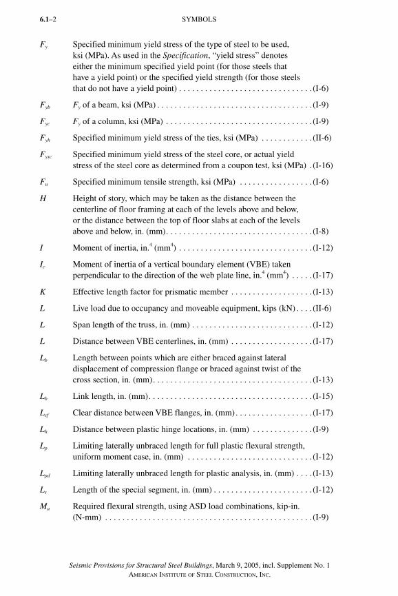
Seismic Provisions for Structural Steel Buildings, March 9, 2005, incl. Supplement No. 1AMERICAN INSTITUTE OF STEEL CONSTRUCTION, INC.
6.1–2
Fy Specified minimum yield stress of the type of steel to be used, ksi (MPa). As used in the Specification, “yield stress” denotes either the minimum specified yield point (for those steels that have a yield point) or the specified yield strength (for those steels that do not have a yield point) . . . . . . . . . . . . . . . . . . . . . . . . . . . . . . . (I-6)
Fyb Fy of a beam, ksi (MPa) . . . . . . . . . . . . . . . . . . . . . . . . . . . . . . . . . . . . (I-9)
Fyc Fy of a column, ksi (MPa) . . . . . . . . . . . . . . . . . . . . . . . . . . . . . . . . . . (I-9)
Fyh Specified minimum yield stress of the ties, ksi (MPa) . . . . . . . . . . . . (II-6)
F ysc Specified minimum yield stress of the steel core, or actual yield stress of the steel core as determined from a coupon test, ksi (MPa) . (I-16)
Fu Specified minimum tensile strength, ksi (MPa) . . . . . . . . . . . . . . . . . (I-6)
H Height of story, which may be taken as the distance between the centerline of floor framing at each of the levels above and below, or the distance between the top of floor slabs at each of the levels above and below, in. (mm) . . . . . . . . . . . . . . . . . . . . . . . . . . . . . . . . . . (I-8)
I Moment of inertia, in.4 (mm4) . . . . . . . . . . . . . . . . . . . . . . . . . . . . . . . (I-12)
Ic Moment of inertia of a vertical boundary element (VBE) taken perpendicular to the direction of the web plate line, in.4 (mm4) . . . . . (I-17)
K Effective length factor for prismatic member . . . . . . . . . . . . . . . . . . . (I-13)
L Live load due to occupancy and moveable equipment, kips (kN) . . . . (II-6)
L Span length of the truss, in. (mm) . . . . . . . . . . . . . . . . . . . . . . . . . . . . (I-12)
L Distance between VBE centerlines, in. (mm) . . . . . . . . . . . . . . . . . . . (I-17)
Lb Length between points which are either braced against lateral displacement of compression flange or braced against twist of the cross section, in. (mm) . . . . . . . . . . . . . . . . . . . . . . . . . . . . . . . . . . . . . (I-13)
Lb Link length, in. (mm) . . . . . . . . . . . . . . . . . . . . . . . . . . . . . . . . . . . . . . (I-15)
Lcf Clear distance between VBE flanges, in. (mm) . . . . . . . . . . . . . . . . . . (I-17)
Lh Distance between plastic hinge locations, in. (mm) . . . . . . . . . . . . . . (I-9)
Lp Limiting laterally unbraced length for full plastic flexural strength, uniform moment case, in. (mm) . . . . . . . . . . . . . . . . . . . . . . . . . . . . . (I-12)
Lpd Limiting laterally unbraced length for plastic analysis, in. (mm) . . . . (I-13)
Ls Length of the special segment, in. (mm) . . . . . . . . . . . . . . . . . . . . . . . (I-12)
Ma Required flexural strength, using ASD load combinations, kip-in. (N-mm) . . . . . . . . . . . . . . . . . . . . . . . . . . . . . . . . . . . . . . . . . . . . . . . . (I-9)
SYMBOLS
SeismicProv1.indd 2SeismicProv1.indd 2 9/8/06 3:59:11 PM9/8/06 3:59:11 PMProcess BlackProcess Black
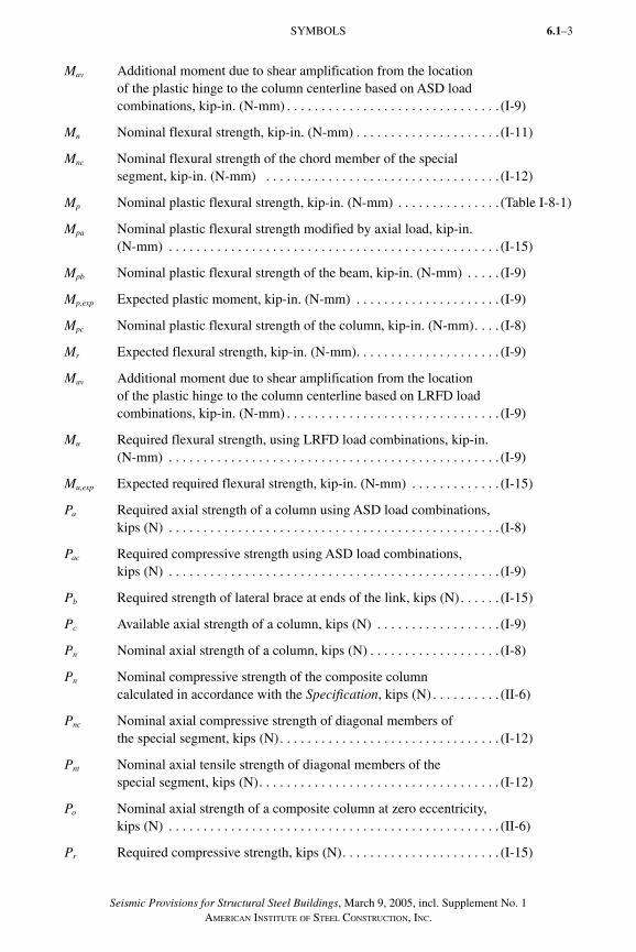
Seismic Provisions for Structural Steel Buildings, March 9, 2005, incl. Supplement No. 1AMERICAN INSTITUTE OF STEEL CONSTRUCTION, INC.
6.1–3
Mav Additional moment due to shear amplification from the location of the plastic hinge to the column centerline based on ASD load combinations, kip-in. (N-mm) . . . . . . . . . . . . . . . . . . . . . . . . . . . . . . . (I-9)
Mn Nominal flexural strength, kip-in. (N-mm) . . . . . . . . . . . . . . . . . . . . . (I-11)
Mnc Nominal flexural strength of the chord member of the special segment, kip-in. (N-mm) . . . . . . . . . . . . . . . . . . . . . . . . . . . . . . . . . . (I-12)
Mp Nominal plastic flexural strength, kip-in. (N-mm) . . . . . . . . . . . . . . . (Table I-8-1)
Mpa Nominal plastic flexural strength modified by axial load, kip-in. (N-mm) . . . . . . . . . . . . . . . . . . . . . . . . . . . . . . . . . . . . . . . . . . . . . . . . (I-15)
Mpb Nominal plastic flexural strength of the beam, kip-in. (N-mm) . . . . . (I-9)
Mp,exp Expected plastic moment, kip-in. (N-mm) . . . . . . . . . . . . . . . . . . . . . (I-9)
Mpc Nominal plastic flexural strength of the column, kip-in. (N-mm) . . . . (I-8)
Mr Expected flexural strength, kip-in. (N-mm) . . . . . . . . . . . . . . . . . . . . . (I-9)
Muv Additional moment due to shear amplification from the location of the plastic hinge to the column centerline based on LRFD load combinations, kip-in. (N-mm) . . . . . . . . . . . . . . . . . . . . . . . . . . . . . . . (I-9)
Mu Required flexural strength, using LRFD load combinations, kip-in. (N-mm) . . . . . . . . . . . . . . . . . . . . . . . . . . . . . . . . . . . . . . . . . . . . . . . . (I-9)
Mu,exp Expected required flexural strength, kip-in. (N-mm) . . . . . . . . . . . . . (I-15)
Pa Required axial strength of a column using ASD load combinations, kips (N) . . . . . . . . . . . . . . . . . . . . . . . . . . . . . . . . . . . . . . . . . . . . . . . . (I-8)
Pac Required compressive strength using ASD load combinations, kips (N) . . . . . . . . . . . . . . . . . . . . . . . . . . . . . . . . . . . . . . . . . . . . . . . . (I-9)
Pb Required strength of lateral brace at ends of the link, kips (N) . . . . . . (I-15)
Pc Available axial strength of a column, kips (N) . . . . . . . . . . . . . . . . . . (I-9)
Pn Nominal axial strength of a column, kips (N) . . . . . . . . . . . . . . . . . . . (I-8)
Pn Nominal compressive strength of the composite column calculated in accordance with the Specification, kips (N) . . . . . . . . . . (II-6)
Pnc Nominal axial compressive strength of diagonal members of the special segment, kips (N) . . . . . . . . . . . . . . . . . . . . . . . . . . . . . . . . (I-12)
Pnt Nominal axial tensile strength of diagonal members of the special segment, kips (N) . . . . . . . . . . . . . . . . . . . . . . . . . . . . . . . . . . . (I-12)
Po Nominal axial strength of a composite column at zero eccentricity, kips (N) . . . . . . . . . . . . . . . . . . . . . . . . . . . . . . . . . . . . . . . . . . . . . . . . (II-6)
Pr Required compressive strength, kips (N) . . . . . . . . . . . . . . . . . . . . . . . (I-15)
SYMBOLS
SeismicProv1.indd 3SeismicProv1.indd 3 9/8/06 3:59:11 PM9/8/06 3:59:11 PMProcess BlackProcess Black
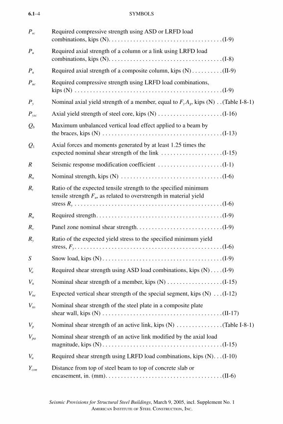
Seismic Provisions for Structural Steel Buildings, March 9, 2005, incl. Supplement No. 1AMERICAN INSTITUTE OF STEEL CONSTRUCTION, INC.
6.1–4
Prc Required compressive strength using ASD or LRFD load combinations, kips (N) . . . . . . . . . . . . . . . . . . . . . . . . . . . . . . . . . . . . . (I-9)
Pu Required axial strength of a column or a link using LRFD load combinations, kips (N) . . . . . . . . . . . . . . . . . . . . . . . . . . . . . . . . . . . . . (I-8)
Pu Required axial strength of a composite column, kips (N) . . . . . . . . . . (II-9)
Puc Required compressive strength using LRFD load combinations, kips (N) . . . . . . . . . . . . . . . . . . . . . . . . . . . . . . . . . . . . . . . . . . . . . . . . (I-9)
Py Nominal axial yield strength of a member, equal to Fy Ag, kips (N) . . (Table I-8-1)
Pysc Axial yield strength of steel core, kips (N) . . . . . . . . . . . . . . . . . . . . . (I-16)
Qb Maximum unbalanced vertical load effect applied to a beam by the braces, kips (N) . . . . . . . . . . . . . . . . . . . . . . . . . . . . . . . . . . . . . . . (I-13)
Q1 Axial forces and moments generated by at least 1.25 times the expected nominal shear strength of the link . . . . . . . . . . . . . . . . . . . . (I-15)
R Seismic response modification coefficient . . . . . . . . . . . . . . . . . . . . . (I-1)
Rn Nominal strength, kips (N) . . . . . . . . . . . . . . . . . . . . . . . . . . . . . . . . . (I-6)
Rt Ratio of the expected tensile strength to the specified minimum tensile strength F u, as related to overstrength in material yield stress Ry . . . . . . . . . . . . . . . . . . . . . . . . . . . . . . . . . . . . . . . . . . . . . . . . (I-6)
Ru Required strength . . . . . . . . . . . . . . . . . . . . . . . . . . . . . . . . . . . . . . . . . (I-9)
Rv Panel zone nominal shear strength . . . . . . . . . . . . . . . . . . . . . . . . . . . . (I-9)
Ry Ratio of the expected yield stress to the specified minimum yield stress, Fy . . . . . . . . . . . . . . . . . . . . . . . . . . . . . . . . . . . . . . . . . . . . . . . . (I-6)
S Snow load, kips (N) . . . . . . . . . . . . . . . . . . . . . . . . . . . . . . . . . . . . . . . (I-9)
Va Required shear strength using ASD load combinations, kips (N) . . . . (I-9)
Vn Nominal shear strength of a member, kips (N) . . . . . . . . . . . . . . . . . . (I-15)
Vne Expected vertical shear strength of the special segment, kips (N) . . . (I-12)
Vns Nominal shear strength of the steel plate in a composite plate shear wall, kips (N) . . . . . . . . . . . . . . . . . . . . . . . . . . . . . . . . . . . . . . . (II-17)
Vp Nominal shear strength of an active link, kips (N) . . . . . . . . . . . . . . . (Table I-8-1)
Vpa Nominal shear strength of an active link modified by the axial load magnitude, kips (N) . . . . . . . . . . . . . . . . . . . . . . . . . . . . . . . . . . . . . . . (I-15)
Vu Required shear strength using LRFD load combinations, kips (N) . . . (I-10)
Ycon Distance from top of steel beam to top of concrete slab or encasement, in. (mm) . . . . . . . . . . . . . . . . . . . . . . . . . . . . . . . . . . . . . . (II-6)
SYMBOLS
SeismicProv1.indd 4SeismicProv1.indd 4 9/8/06 3:59:11 PM9/8/06 3:59:11 PMProcess BlackProcess Black
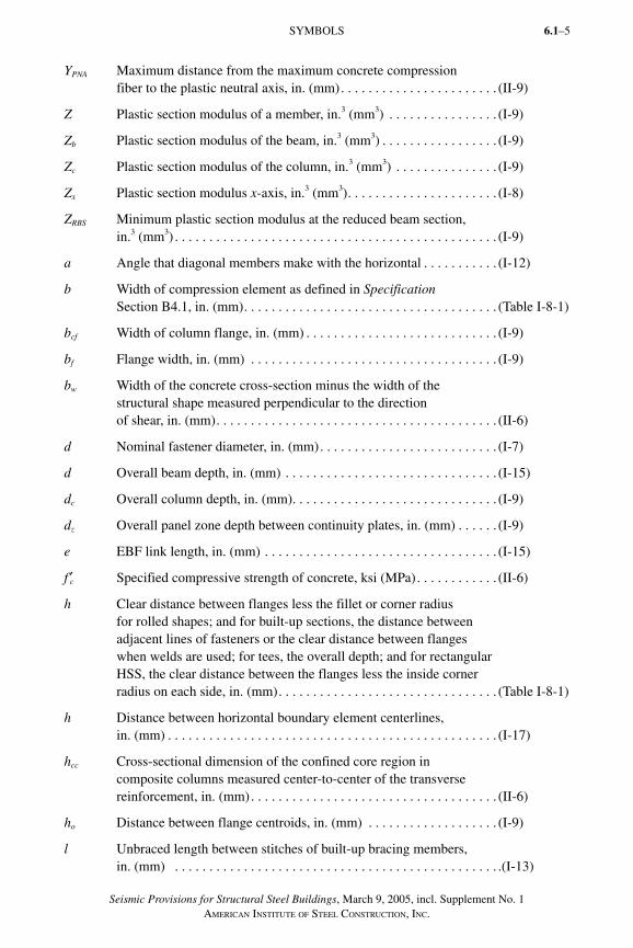
Seismic Provisions for Structural Steel Buildings, March 9, 2005, incl. Supplement No. 1AMERICAN INSTITUTE OF STEEL CONSTRUCTION, INC.
6.1–5
YPNA Maximum distance from the maximum concrete compression fiber to the plastic neutral axis, in. (mm) . . . . . . . . . . . . . . . . . . . . . . . (II-9)
Z Plastic section modulus of a member, in.3 (mm3) . . . . . . . . . . . . . . . . (I-9)
Zb Plastic section modulus of the beam, in.3 (mm3) . . . . . . . . . . . . . . . . . (I-9)
Zc Plastic section modulus of the column, in.3 (mm3) . . . . . . . . . . . . . . . (I-9)
Zx Plastic section modulus x-axis, in.3 (mm3) . . . . . . . . . . . . . . . . . . . . . . (I-8)
ZRBS Minimum plastic section modulus at the reduced beam section, in.3 (mm3) . . . . . . . . . . . . . . . . . . . . . . . . . . . . . . . . . . . . . . . . . . . . . . . (I-9)
a Angle that diagonal members make with the horizontal . . . . . . . . . . . (I-12)
b Width of compression element as defined in Specification Section B4.1, in. (mm) . . . . . . . . . . . . . . . . . . . . . . . . . . . . . . . . . . . . . (Table I-8-1)
bcf Width of column flange, in. (mm) . . . . . . . . . . . . . . . . . . . . . . . . . . . . (I-9)
bf Flange width, in. (mm) . . . . . . . . . . . . . . . . . . . . . . . . . . . . . . . . . . . . (I-9)
bw Width of the concrete cross-section minus the width of the structural shape measured perpendicular to the direction of shear, in. (mm) . . . . . . . . . . . . . . . . . . . . . . . . . . . . . . . . . . . . . . . . . (II-6)
d Nominal fastener diameter, in. (mm) . . . . . . . . . . . . . . . . . . . . . . . . . . (I-7)
d Overall beam depth, in. (mm) . . . . . . . . . . . . . . . . . . . . . . . . . . . . . . . (I-15)
dc Overall column depth, in. (mm) . . . . . . . . . . . . . . . . . . . . . . . . . . . . . . (I-9)
dz Overall panel zone depth between continuity plates, in. (mm) . . . . . . (I-9)
e EBF link length, in. (mm) . . . . . . . . . . . . . . . . . . . . . . . . . . . . . . . . . . (I-15)
f ′c Specified compressive strength of concrete, ksi (MPa) . . . . . . . . . . . . (II-6)
h Clear distance between flanges less the fillet or corner radius for rolled shapes; and for built-up sections, the distance between adjacent lines of fasteners or the clear distance between flanges when welds are used; for tees, the overall depth; and for rectangular HSS, the clear distance between the flanges less the inside corner radius on each side, in. (mm) . . . . . . . . . . . . . . . . . . . . . . . . . . . . . . . . (Table I-8-1)
h Distance between horizontal boundary element centerlines, in. (mm) . . . . . . . . . . . . . . . . . . . . . . . . . . . . . . . . . . . . . . . . . . . . . . . . (I-17)
hcc Cross-sectional dimension of the confined core region in composite columns measured center-to-center of the transverse reinforcement, in. (mm) . . . . . . . . . . . . . . . . . . . . . . . . . . . . . . . . . . . . (II-6)
ho Distance between flange centroids, in. (mm) . . . . . . . . . . . . . . . . . . . (I-9)
l Unbraced length between stitches of built-up bracing members, in. (mm) . . . . . . . . . . . . . . . . . . . . . . . . . . . . . . . . . . . . . . . . . . . . . . . .(I-13)
SYMBOLS
SeismicProv1.indd 5SeismicProv1.indd 5 9/8/06 3:59:12 PM9/8/06 3:59:12 PMProcess BlackProcess Black
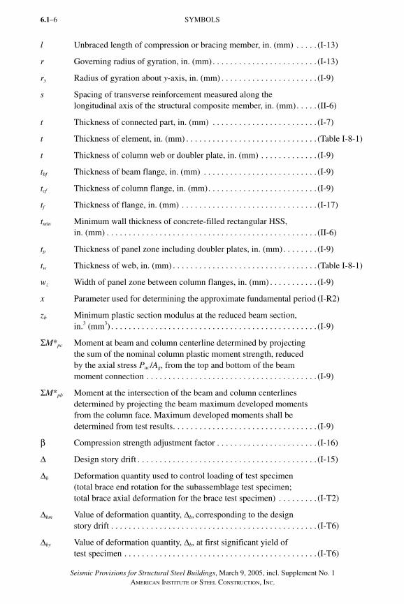
Seismic Provisions for Structural Steel Buildings, March 9, 2005, incl. Supplement No. 1AMERICAN INSTITUTE OF STEEL CONSTRUCTION, INC.
6.1–6
l Unbraced length of compression or bracing member, in. (mm) . . . . . (I-13)
r Governing radius of gyration, in. (mm) . . . . . . . . . . . . . . . . . . . . . . . . (I-13)
ry Radius of gyration about y-axis, in. (mm) . . . . . . . . . . . . . . . . . . . . . . (I-9)
s Spacing of transverse reinforcement measured along the longitudinal axis of the structural composite member, in. (mm) . . . . . (II-6)
t Thickness of connected part, in. (mm) . . . . . . . . . . . . . . . . . . . . . . . . (I-7)
t Thickness of element, in. (mm) . . . . . . . . . . . . . . . . . . . . . . . . . . . . . . (Table I-8-1)
t Thickness of column web or doubler plate, in. (mm) . . . . . . . . . . . . . (I-9)
tbf Thickness of beam flange, in. (mm) . . . . . . . . . . . . . . . . . . . . . . . . . . (I-9)
tcf Thickness of column flange, in. (mm) . . . . . . . . . . . . . . . . . . . . . . . . . (I-9)
tf Thickness of flange, in. (mm) . . . . . . . . . . . . . . . . . . . . . . . . . . . . . . . (I-17)
tmin Minimum wall thickness of concrete-filled rectangular HSS, in. (mm) . . . . . . . . . . . . . . . . . . . . . . . . . . . . . . . . . . . . . . . . . . . . . . . . (II-6)
tp Thickness of panel zone including doubler plates, in. (mm) . . . . . . . . (I-9)
tw Thickness of web, in. (mm) . . . . . . . . . . . . . . . . . . . . . . . . . . . . . . . . . (Table I-8-1)
wz Width of panel zone between column flanges, in. (mm) . . . . . . . . . . . (I-9)
x Parameter used for determining the approximate fundamental period (I-R2)
zb Minimum plastic section modulus at the reduced beam section, in.3 (mm3) . . . . . . . . . . . . . . . . . . . . . . . . . . . . . . . . . . . . . . . . . . . . . . . (I-9)
ΣM*pc Moment at beam and column centerline determined by projecting the sum of the nominal column plastic moment strength, reduced by the axial stress Puc/Ag, from the top and bottom of the beam moment connection . . . . . . . . . . . . . . . . . . . . . . . . . . . . . . . . . . . . . . . (I-9)
ΣM*pb Moment at the intersection of the beam and column centerlines determined by projecting the beam maximum developed moments from the column face. Maximum developed moments shall be determined from test results . . . . . . . . . . . . . . . . . . . . . . . . . . . . . . . . . (I-9)
β Compression strength adjustment factor . . . . . . . . . . . . . . . . . . . . . . . (I-16)
Δ Design story drift . . . . . . . . . . . . . . . . . . . . . . . . . . . . . . . . . . . . . . . . . (I-15)
Δb Deformation quantity used to control loading of test specimen (total brace end rotation for the subassemblage test specimen; total brace axial deformation for the brace test specimen) . . . . . . . . . (I-T2)
Δbm Value of deformation quantity, Δb, corresponding to the design story drift . . . . . . . . . . . . . . . . . . . . . . . . . . . . . . . . . . . . . . . . . . . . . . . (I-T6)
Δby Value of deformation quantity, Δb, at first significant yield of test specimen . . . . . . . . . . . . . . . . . . . . . . . . . . . . . . . . . . . . . . . . . . . . (I-T6)
SYMBOLS
SeismicProv1.indd 6SeismicProv1.indd 6 9/8/06 3:59:12 PM9/8/06 3:59:12 PMProcess BlackProcess Black
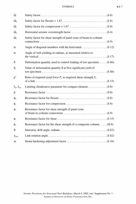
Seismic Provisions for Structural Steel Buildings, March 9, 2005, incl. Supplement No. 1AMERICAN INSTITUTE OF STEEL CONSTRUCTION, INC.
6.1–7
Ω Safety factor . . . . . . . . . . . . . . . . . . . . . . . . . . . . . . . . . . . . . . . . . . . . . (I-6)
Ωb Safety factor for flexure = 1.67 . . . . . . . . . . . . . . . . . . . . . . . . . . . . . . (I-8)
Ωc Safety factor for compression = 1.67 . . . . . . . . . . . . . . . . . . . . . . . . . . (I-8)
Ωo Horizontal seismic overstrength factor . . . . . . . . . . . . . . . . . . . . . . . . (I-4)
Ωv Safety factor for shear strength of panel zone of beam-to-column con nec tions . . . . . . . . . . . . . . . . . . . . . . . . . . . . . . . . . . . . . . . . . . . . . (I-9)
α Angle of diagonal members with the horizontal . . . . . . . . . . . . . . . . . (I-12)
α Angle of web yielding in radians, as measured relative to the vertical . . . . . . . . . . . . . . . . . . . . . . . . . . . . . . . . . . . . . . . . . . . . . . (I-17)
δ Deformation quantity used to control loading of test specimen . . . . . (I-S6)
δy Value of deformation quantity δ at first significant yield of test specimen . . . . . . . . . . . . . . . . . . . . . . . . . . . . . . . . . . . . . . . . . . . . (I-S6)
ρ′ Ratio of required axial force Pu to required shear strength Vu of a link . . . . . . . . . . . . . . . . . . . . . . . . . . . . . . . . . . . . . . . . . . . . . . . . (I-15)
λp, λps Limiting slenderness parameter for compact element . . . . . . . . . . . . . (I-8)
φ Resistance factor . . . . . . . . . . . . . . . . . . . . . . . . . . . . . . . . . . . . . . . . . (I-6)
φb Resistance factor for flexure . . . . . . . . . . . . . . . . . . . . . . . . . . . . . . . . (I-8)
φc Resistance factor for compression . . . . . . . . . . . . . . . . . . . . . . . . . . . . (I-8)
φv Resistance factor for shear strength of panel zone of beam-to-column con nec tions . . . . . . . . . . . . . . . . . . . . . . . . . . . . . (I-9)
φv Resistance factor for shear . . . . . . . . . . . . . . . . . . . . . . . . . . . . . . . . . . (I-15)
φv Resistance factor for the shear strength of a composite column . . . . . (II-6)
θ Interstory drift angle, radians . . . . . . . . . . . . . . . . . . . . . . . . . . . . . . . . (I-S3)
γtotal Link rotation angle . . . . . . . . . . . . . . . . . . . . . . . . . . . . . . . . . . . . . . . . (I-S2)
ω Strain hardening adjustment factor . . . . . . . . . . . . . . . . . . . . . . . . . . . (I-16)
SYMBOLS
SeismicProv1.indd 7SeismicProv1.indd 7 9/8/06 3:59:13 PM9/8/06 3:59:13 PMProcess BlackProcess Black

Seismic Provisions for Structural Steel Buildings, March 9, 2005, incl. Supplement No. 1AMERICAN INSTITUTE OF STEEL CONSTRUCTION, INC.
6.1–8
SeismicProv1.indd 8SeismicProv1.indd 8 9/8/06 3:59:13 PM9/8/06 3:59:13 PMProcess BlackProcess Black
Seismic Provisions for Structural Steel Buildings, March 9, 2005, incl. Supplement No. 1AMERICAN INSTITUTE OF STEEL CONSTRUCTION, INC.
6.1–9
PART I. STRUCTURAL STEEL BUILDINGS
GLOSSARY
Terms that appear in this glossary are generally italicized throughout these Provisions and Commentary, where they first appear within a subsection.
Notes:
(1) Terms designated with † are common AISI-AISC terms that are coordinated between the two standards developers.
(2) Terms designated with * are usually qualified by the type of load effect, for example, nominal tensile strength, available compressive strength, design flexural strength.
(3) Terms designated with ** are usually qualified by the type of component, for example, web local buckling, flange local bending.
Adjusted brace strength. Strength of a brace in a buckling-restrained braced frame at deformations corresponding to 2.0 times the design story drift.
Allowable strength*†. Nominal strength divided by the safety factor, Rn / Ω.
Applicable building code (ABC) †. Building code under which the structure is designed.
Amplified seismic load. Horizontal component of earthquake load E multiplied by Ωo, where E and the horizontal component of E are specified in the applicable building code.
Authority having jurisdiction (AHJ). Organization, political subdivision, office or individual charged with the responsibility of administering and enforcing the provisions of this standard.
Available strength*†. Design strength or allowable strength, as appropriate.
ASD (Allowable Strength Design). Method of proportioning structural components such that the allowable strength equals or exceeds the required strength of the component under the action of the ASD load combinations.
ASD load combination†. Load combination in the applicable building code intended for allowable strength design (allowable stress design).
Buckling-restrained braced frame (BRBF). Diagonally braced frame safisfying the requirements of Section 16 in which all members of the bracing system are subjected primarily to axial forces and in which the limit state of compression buckling of braces is precluded at forces and deformations corresponding to 2.0 times the design story drift.
Buckling-restraining system. System of restraints that limits buckling of the steel core in BRBF. This system includes the casing on the steel core and structural elements adjoining its connections. The buckling-restraining system is intended to permit the transverse expansion and longitudinal contraction of the steel core for deformations corresponding to 2.0 times the design story drift.
SeismicProv1.indd 9SeismicProv1.indd 9 9/8/06 3:59:13 PM9/8/06 3:59:13 PMProcess BlackProcess Black
Seismic Provisions for Structural Steel Buildings, March 9, 2005, incl. Supplement No. 1AMERICAN INSTITUTE OF STEEL CONSTRUCTION, INC.
6.1–10
Casing. Element that resists forces transverse to the axis of the brace thereby restraining buckling of the core. The casing requires a means of delivering this force to the remainder of the buckling-restraining system. The casing resists little or no force in the axis of the brace.
Column base. Assemblage of plates, connectors, bolts, and rods at the base of a column used to transmit forces between the steel superstructure and the foundation.
Continuity plates. Column stiffeners at the top and bottom of the panel zone; also known as transverse stiffeners.
Contractor. Fabricator or erector, as applicable.
Demand critical weld. Weld so designated by these Provisions.
Design earthquake. The earthquake represented by the design response spectrum as specified in the applicable building code.
Design story drift. Amplified story drift (drift under the design earthquake, including the effects of inelastic action), determined as specified in the applicable building code.
Design strength*†. Resistance factor multiplied by the nominal strength, φRn.
Diagonal bracing. Inclined structural members carrying primarily axial load that are employed to enable a structural frame to act as a truss to resist lateral loads.
Dual system. Structural system with the following features: (1) an essentially complete space frame that provides support for gravity loads; (2) re sist ance to lateral load provided by moment frames (SMF, IMF or OMF) that are capable of resisting at least 25 percent of the base shear, and concrete or steel shear walls, or steel braced frames (EBF, SCBF or OCBF); and (3) each system designed to resist the total lateral load in proportion to its relative rigidity.
Ductile limit state. Ductile limit states include member and connection yielding, bearing deformation at bolt holes, as well as buckling of members that conform to the width-thickness limitations of Table I-8-1. Fracture of a member or of a connection, or buckling of a connection element, is not a ductile limit state.
Eccentrically braced frame (EBF). Diagonally braced frame meeting the requirements of Section 15 that has at least one end of each bracing member connected to a beam a short distance from another beam-to-brace connection or a beam-to-column connection.
Exempted column. Column not meeting the requirements of Equation 9-3 for SMF.
Expected yield strength. Yield strength in tension of a member, equal to the expected yield stress multiplied by Ag.
Expected tensile strength *. Tensile strength of a member, equal to the specified minimum tensile strength, Fu, multiplied by Rt.
Expected yield stress. Yield stress of the material, equal to the specified minimum yield stress, F y, multiplied by R y .
PART I – GLOSSARY
SeismicProv1.indd 10SeismicProv1.indd 10 9/8/06 3:59:13 PM9/8/06 3:59:13 PMProcess BlackProcess Black
6.1–11
Intermediate moment frame (IMF). Moment frame system that meets the re quirements of Section 10.
Interstory drift angle. Interstory displacement divided by story height, radians.
Inverted-V-braced frame. See V-braced frame.
k-area. The k-area is the region of the web that extends from the tangent point of the web and the flange-web fillet (AISC “k” dimension) a distance of 1 ½ in. (38 mm) into the web beyond the “k” dimension.
K-braced frame. A bracing configuration in which braces connect to a column at a location with no diaphragm or other out-of-plane support.
Lateral bracing member. Member that is designed to inhibit lateral buckling or lateral-tor sional buckling of primary framing members.
Link. In EBF, the segment of a beam that is located between the ends of two diagonal braces or between the end of a diag onal brace and a column. The length of the link is defined as the clear dist ance between the ends of two diag onal braces or between the diagonal brace and the column face.
Link intermediate web stiffeners. Vertical web stiffeners placed within the link in EBF.
Link rotation angle. Inelastic angle between the link and the beam outside of the link when the total story drift is equal to the design story drift.
Link shear design stre ngth. Lesser of the available shear strength of the link developed from the moment or shear strength of the link.
Lowest Anticipated Service Temperature (LAST). The lowest 1-hour average temperature with a 100-year mean recurrence interval.
LRFD (Load and Resistance Factor Design)†. Method of proportioning structural components such that the design strength equals or exceeds the required strength of the component under the action of the LRFD load combinations.
LRFD Load Combination†. Load combination in the applicable building code intended for strength design (load and resistance factor design).
Measured flexural resistance. Bending moment measured in a beam at the face of the column, for a beam-to-column test specimen tested in accordance with Appendix S.
Nominal load†. Magnitude of the load specified by the applicable building code.
Nominal strength*†. Strength of a structure or component (without the resistance factor or safety factor applied) to resist the load effects, as determined in accordance with this Specification.
Ordinary concentrically braced frame (OCBF). Diagonally braced frame meeting the requirements of Section 14 in which all members of the bracing system are subjected primarily to axial forces.
Ordin ary moment frame (OMF). Moment frame system that meets the re quirements of Section 11.
Seismic Provisions for Structural Steel Buildings, March 9, 2005, incl. Supplement No. 1AMERICAN INSTITUTE OF STEEL CONSTRUCTION, INC.
PART I – GLOSSARY
SeismicProv1.indd 11SeismicProv1.indd 11 9/8/06 3:59:13 PM9/8/06 3:59:13 PMProcess BlackProcess Black
Seismic Provisions for Structural Steel Buildings, March 9, 2005, incl. Supplement No. 1AMERICAN INSTITUTE OF STEEL CONSTRUCTION, INC.
6.1–12
Overstrength factor, Ωo. Factor specified by the applicable building code in order to determine the amplified seismic load, where required by these Provisions.
Prequalified connection. Connection that complies with the requirements of Appendix P or ANSI/AISC 358.
Protected zone. Area of members in which limitations apply to fabrication and attachments. See Section 7.4.
Prototype. The connection or brace design that is to be used in the building (SMF, IMF, EBF, and BRBF).
Provisions. Refers to this document, the AISC Seismic Provisions for Structural Steel Buildings (ANSI/AISC 341).
Quality assurance plan. Written description of qualifications, procedures, quality inspections, resources, and records to be used to provide assurance that the structure complies with the engineer’s quality requirements, specifications and contract documents.
Reduced beam section. Reduction in cross section over a discrete length that promotes a zone of inelasticity in the member.
Required strength*†. Forces, stresses, and deformations produced in a structural component, determined by either structural analysis, for the LRFD or ASD load combinations, as appropriate, or as specified by the Specification and these Provisions.
Resistance factor, φ†. Factor that accounts for unavoidable deviations of the nominal strength from the actual strength and for the manner and consequences of failure.
Safety factor, Ω†. Factor that accounts for deviations of the actual strength from the nominal strength, deviations of the actual load from the nominal load, uncertainties in the analysis that transforms the load into a load effect, and for the manner and consequences of failure.
Seismic design category. Classification assigned to a building by the applicable building code based upon its seismic use group and the design spectral response acceleration coefficients.
Seismic load resisting system (SLRS). Assembly of structural elements in the building that resists seismic loads, including struts, collectors, chords, diaphragms and trusses.
Seismic response modification coefficient, R. Factor that reduces seismic load effects to strength level as specified by the applicable building code.
Seismic use group. Classification assigned to a structure based on its use as specified by the applicable building code.
Special concentrically braced frame (SCBF). Diagonally braced frame meeting the requirements of Section 13 in which all members of the bracing system are subjected primarily to axial forces.
Special moment frame (SMF). Moment frame system that meets the requirements of Section 9.
Special plate shear wall (SPSW). Plate shear wall system that meets the requirements of Section 17.
PART I – GLOSSARY
SeismicProv1.indd 12SeismicProv1.indd 12 9/8/06 3:59:14 PM9/8/06 3:59:14 PMProcess BlackProcess Black
Seismic Provisions for Structural Steel Buildings, March 9, 2005, incl. Supplement No. 1AMERICAN INSTITUTE OF STEEL CONSTRUCTION, INC.
6.1–13
Special truss moment frame (STMF). Truss moment frame system that meets the requi rements of Section 12.
Specification. Refers to the AISC Specification for Structural Steel Buildings (ANSI/AISC 360).
Static yield strength. Strength of a structural member or connection determined on the basis of testing conducted under slow monotonic loading until failure.
Steel core. Axial-force-resisting element of braces in BRBF. The steel core contains a yielding segment and connections to transfer its axial force to adjoining elements; it may also contain projections beyond the casing and transition segments between the projections and yielding segment.
Tested connection. Connection that complies with the requirements of Appendix S.
V-braced frame. Concentrically braced frame (SCBF, OCBF or BRBF) in which a pair of diagonal braces located either above or below a beam is conn ected to a single point within the clear beam span . Where the diag onal braces are below the beam, the system is also referred to as an inverted-V-braced frame.
X-braced frame. Concentrically braced frame (OCBF or SCBF) in which a pair of diagonal braces crosses near the mid-length of the braces.
Y-braced frame. Eccentrically braced frame (EBF) in which the stem of the Y is the link of the EBF system.
PART I – GLOSSARY
SeismicProv1.indd 13SeismicProv1.indd 13 9/8/06 3:59:14 PM9/8/06 3:59:14 PMProcess BlackProcess Black

Seismic Provisions for Structural Steel Buildings, March 9, 2005, incl. Supplement No. 1AMERICAN INSTITUTE OF STEEL CONSTRUCTION, INC.
6.1–14
SeismicProv1.indd 14SeismicProv1.indd 14 9/8/06 3:59:14 PM9/8/06 3:59:14 PMProcess BlackProcess Black
Seismic Provisions for Structural Steel Buildings, March 9, 2005, incl. Supplement No. 1AMERICAN INSTITUTE OF STEEL CONSTRUCTION, INC.
Sect. 2.]
1. SCOPEThe Seismic Provisions for Structural Steel Buildings, hereinafter referred to as these Provisions, shall govern the design, fabrication and erection of structural steel members and connections in the seismic load resisting systems (SLRS) and splices in columns that are not part of the SLRS, in buildings and other structures, where other structures are defined as those structures designed, fab-ricated and erected in a manner similar to buildings, with building-like vertical and lateral load-resisting-elements. These Provisions shall apply when the seis-mic response modification coefficient, R, (as specified in the applicable building code) is taken greater than 3, regardless of the seismic design category. When the seismic response modification coefficient, R, is taken as 3 or less, the structure is not required to satisfy these Provisions, unless specifically required by the applicable building code.
These Provisions shall be applied in conjunc tion with the AISC Specification for Structural Steel Buildings, hereinafter referred to as the Specification. Members and connections of the SLRS shall satisfy the requirements of the applicable building code, the Specification, and these Provisions.
Wherever these provisions refer to the applicable building code and there is no local building code, the loads, load combinations, system limitations and general design requirements shall be those in SEI/ASCE 7.
User Note: The applicable building code generally restricts buildings de-signed with an R factor of 3 or less to seismic design categories (SDC) A, B or C; however, some systems such as cantilever columns that have R factors less than 3 are permitted in SDC D and above and these Provisions apply. See the applicable building code for specific system limitations.
Part I includes a Glossary that is specifically applicable to this Part, and Appen-dices P, Q, R, S, T, W and X.
2. REFERENCED SPECIFICATIONS, CODES, AND STANDARDSThe documents referenced in these Provisions shall include those listed in Speci-fication Section A2 with the following additions and modifications:
American Institute of Steel Construction (AISC)Specification for Structural Steel Buildings, ANSI/AISC 360-05Prequalified Connections for Special and Intermediate Steel Moment Frames
for Seismic Applications, ANSI/AISC 358-05
American Society for Nondestructive Testing (ASNT)Recommended Practice for the Training and Testing of Nondestructive Testing
Personnel, ASNT SNT TC-1a-2001Standard for the Qualification and Certification of Nondestructive Testing
Personnel, ANSI/ASNT CP-189-2001
6.1–15PART I – REFERENCED SPECIFICATIONS, CODES, AND STANDARDS
SeismicProv1.indd 15SeismicProv1.indd 15 9/8/06 3:59:14 PM9/8/06 3:59:14 PMProcess BlackProcess Black
Seismic Provisions for Structural Steel Buildings, March 9, 2005, incl. Supplement No. 1AMERICAN INSTITUTE OF STEEL CONSTRUCTION, INC.
[Sect. 2.6.1–16
American Welding Society (AWS)Standard Methods for Determination of the Diffusible Hydrogen Content
of Martensitic, Bainitic, and Ferritic Steel Weld Metal Produced by Arc Welding, AWS A4.3-93R
Standard Methods for Mechanical Testing of Welds-U.S. Customary, ANSI/AWS B4.0-98
Standard Methods for Mechanical Testing of Welds–Metric Only, ANSI/AWS B4.0M:2000
Standard for the Qualification of Welding Inspectors, AWS B5.1:2003 Oxygen Cutting Surface Roughness Gauge and Wall Chart for Criteria
Describing Oxygen-Cut Surfaces, AWS C4.1
Federal Emergency Management Agency (FEMA)Recommended Seismic Design Criteria for New Steel Moment-Frame
Buildings, FEMA 350, July 2000
3. GENERAL SEISMIC DESIGN REQUIREMENTSThe required strength and other seismic provisions for seismic design categories (SDC) and seismic use groups and the limitations on height and irregularity shall be as specified in the applicable building code.
The design story drift shall be determined as required in the applicable building code.
4. LOADS, LOAD COMB INATIONS, AND NOMINAL STRENGTHS
4.1. Loads and Load CombinationsThe loads and load combinations shall be as stipulated by the applicable build-ing code. Where amplified seismic loads are required by these Provisions, the horizontal portion of the earthquake load E (as defined in the applicable building code) shall be multiplied by the overstrength factor, Ωo, prescribed by the appli-cable building code.
User Note: When not defined in the applicable building code, Ωo should be taken from SEI/ASCE 7.
4.2. Nominal StrengthThe nominal strength of systems, members and connections shall comply with the Specification, except as modified throughout these Provisions.
5. STRUCTURAL DESIGN DRAWINGS AND SPECIFICATIONS, SHOP DRAWINGS, AND ERECTION DRAWINGS
PART I – REFERENCED SPECIFICATIONS, CODES, AND STANDARDS
SeismicProv1.indd 16SeismicProv1.indd 16 9/8/06 3:59:14 PM9/8/06 3:59:14 PMProcess BlackProcess Black
Seismic Provisions for Structural Steel Buildings, March 9, 2005, incl. Supplement No. 1AMERICAN INSTITUTE OF STEEL CONSTRUCTION, INC.
6.1–17
5.1. Structural Design Drawings and SpecificationsStructural design drawings and specifications shall show the work to be per-formed, and include items required by the Specification and the following, as applicable:
(1) Designation of the seismic load resisting system (SLRS)
(2) Designation of the members and connections that are part of the SLRS
(3) Configuration of the connections
(4) Connection material specifications and sizes
(5) Locations of demand critical welds
(6) Lowest anticipated service temperature (LAST) of the steel structure, if the structure is not enclosed and maintained at a temperature of 50 °F (10 °C) or higher
(7) Locations and dimensions of protected zones
(8) Locations where gusset plates are to be detailed to accommodate inelastic rotation
(9) Welding requirements as specified in Appendix W, Section W2.1.
User Note: These Provisions should be consistent with the Code of Stan-dard Practice, as designated in Section A4 of the Specification. There may be specific connections and applications for which details are not specifi-cally addressed by the Provisions. If such a condition exists, the contract documents should include appropriate requirements for those applications. These may include nondestructive testing requirements beyond those in Ap-pendix Q, bolt hole fabrication requirements beyond those permitted by the Specification, bolting requirements other than those in the Research Council on Structural Connections (RCSC) Specification for Structural Joints Using ASTM A325 or A490 Bolts, or welding requirements other than those in Appendix W.
5.2. Shop DrawingsShop drawings shall include items required by the Specification and the follow-ing, as applicable:
(1) Designation of the members and connections that are part of the SLRS
(2) Connection material specifications
(3) Locations of demand critical shop welds
(4) Locations and dimensions of protected zones
(5) Gusset plates drawn to scale when they are detailed to accommodate inelastic rotation
(6) Welding requirements as specified in Appendix W, Section W2.2.
Sect. 5.] PART I – STRUCTURAL DESIGN DRAWINGS AND SPECIFICATIONS
SeismicProv1.indd 17SeismicProv1.indd 17 9/8/06 3:59:14 PM9/8/06 3:59:14 PMProcess BlackProcess Black
Seismic Provisions for Structural Steel Buildings, March 9, 2005, incl. Supplement No. 1AMERICAN INSTITUTE OF STEEL CONSTRUCTION, INC.
6.1–18
User Note: There may be specific connections and applications for which details are not specifically addressed by the Provisions. If such a condition exists, the shop drawings should include appropriate requirements for that application. These may include bolt hole fabrication requirements beyond those permitted by the Specification, bolting requirements other than those in the RCSC Specification for Structural Joints Using ASTM A325 or A490 Bolts, and welding requirements other than those in Appendix W. See Sec-tion M1 of the Specification for additional provisions on shop drawings.
5.3. Erection DrawingsErection drawings shall include items required by the Specification and the fol-lowing, as applicable:
(1) Designation of the members and connections that are part of the SLRS
(2) Field connection material specifications and sizes
(3) Locations of demand critical field welds
(4) Locations and dimensions of protected zones
(5) Locations of pretensioned bolts
(6) Field welding requirements as specified in Appendix W, Section W2.3
User Note: There may be specific connections and applications for which details are not specifically addressed by the Provisions. If such a condition exists, the erection drawings should include appropriate requirements for that application. These may include bolting requirements other than those in the RCSC Specification for Structural Joints Using ASTM A325 or A490 Bolts, and welding requirements other than those in Appendix W. See Section M1 of the Specification for additional provisions on erection drawings.
6. MATERIALS
6.1. Material SpecificationsStructural steel used in the seismic load resisting system (SLRS) shall meet the requirements of Specification Section A3.1a, except as modified in these Pro-visions. The specified minimum yield stress of steel to be used for members in which inelastic behavior is expected shall not exceed 50 ksi (345 MPa) for systems defined in Sections 9, 10, 12, 13, 15, 16, and 17 nor 55 ksi (380 MPa) for systems defined in Sections 11 and 14, unless the suitability of the material is determined by testing or other rational criteria. This limitation does not ap-ply to columns for which the only expected inelastic behavior is yielding at the column base.
PART I – STRUCTURAL DESIGN DRAWINGS AND SPECIFICATIONS [Sect. 5.
SeismicProv1.indd 18SeismicProv1.indd 18 9/8/06 3:59:15 PM9/8/06 3:59:15 PMProcess BlackProcess Black
Seismic Provisions for Structural Steel Buildings, March 9, 2005, incl. Supplement No. 1AMERICAN INSTITUTE OF STEEL CONSTRUCTION, INC.
6.1–19
The structural steel used in the SLRS desc ribed in Sect ions 9, 10, 11, 12, 13, 14, 15, 16 and 17 shall meet one of the follow ing ASTM Specif ica tions: A36/A36M, A53/A53M, A500 (Grade B or C), A501, A529/A529M, A572/A572M [Grade 42 (290), 50 (345) or 55 (380)], A588/A588M, A913/A913M [Grade 50 (345), 60 (415) or 65 (450)], A992/A992M, or A1011 HSLAS Grade 55 (380). The structural steel used for column base plates shall meet one of the preceding ASTM specifications or ASTM A283/A283M Grade D.
Other steels and non-steel materials in buckling-restrained braced frames are permitted to be used subject to the requirements of Section 16 and Appendix T.
User Note: This section only covers material properties for structural steel used in the SLRS and included in the definition of structural steel given in Section 2.1 of the AISC Code of Standard Practice. Other steel, such as cables for permanent bracing, is not included.
6.2. Material Properties for Determination of Required Strength of Members and ConnectionsWhen required in these Provisions, the required strength of an element (a mem-ber or a connection) shall be determined from the expected yield stress, Ry Fy , of an adjoining member, where Fy is the specified minimum yield stress of the grade of steel to be used in the adjoining members and Ry is the ratio of the ex-pected yield stress to the specified minimum yield stress, Fy , of that material.
The available strength of the element, φRn for LRFD and Rn/ Ω for ASD, shall be equal to or greater than the required strength, where Rn is the nominal strength of the connection. The expected tensile strength, RtFu, and the expected yield stress, RyFy, are permitted to be used in lieu of Fu and Fy, respectively, in determining the nominal strength, Rn, of rupture and yielding limit states within the same member for which the required strength is determined.
User Note: In several instances a member, or a connection limit state within that member, is required to be designed for forces corresponding to the ex-pected strength of the member itself. Such cases include brace fracture limit states (block shear rupture and net section fracture in the brace in SCBF), the design of the beam outside of the link in EBF, etc. In such cases it is permit-ted to use the expected material strength in the determination of available member strength. For connecting elements and for other members, specified material strength should be used.
The values of Ry and Rt for various steels are given in Table I-6-1. Other values of Ry and Rt shall be permitted if the values are determined by testing of specimens similar in size and source conducted in accordance with the requirements for the specified grade of steel.
PART I – MATERIALSSect. 6.]
SeismicProv1.indd 19SeismicProv1.indd 19 9/8/06 3:59:15 PM9/8/06 3:59:15 PMProcess BlackProcess Black
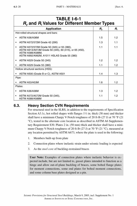
Seismic Provisions for Structural Steel Buildings, March 9, 2005, incl. Supplement No. 1AMERICAN INSTITUTE OF STEEL CONSTRUCTION, INC.
6.1–20
TABLE I-6-1Ry and Rt Values for Different Member Types
Application Ry Rt
Hot-rolled structural shapes and bars:
• ASTM A36/A36M
• ASTM A572/572M Grade 42 (290)
• ASTM A572/572M Grade 50 (345) or 55 (380), ASTM A913/A913M Grade 50 (345), 60 (415), or 65 (450), ASTM A588/A588M, ASTM A992/A992M, A1011 HSLAS Grade 55 (380)
• ASTM A529 Grade 50 (345)
• ASTM A529 Grade 55 (380)
1.5
1.3
1.1
1.2
1.1
1.2
1.1
1.1
1.2
1.2
Hollow structural sections (HSS):
• ASTM A500 (Grade B or C), ASTM A501 1.4 1.3
Pipe:
• ASTM A53/A53M 1.6 1.2
Plates:
• ASTM A36/A36M
• ASTM A572/A572M Grade 50 (345), ASTM A588/A588M
1.3
1.1
1.2
1.2
6.3. Heavy Section CVN RequirementsFor structural steel in the SLRS, in addition to the requirements of Specification Section A3.1c, hot rolled shapes with flanges 12 in. thick (38 mm) and thicker shall have a minimum Charpy V-Notch toughness of 20 ft-lb (27 J) at 70 °F (21 °C), tested in the alternate core location as described in ASTM A6 Supplemen-tary Requirement S30. Plates 2 in. (50 mm) thick and thicker shall have a mini-mum Charpy V-Notch toughness of 20 ft-lb (27 J) at 70 °F (21 °C), measured at any location permitted by ASTM A673, where the plate is used in the following:
1. Members built-up from plate
2. Connection plates where inelastic strain under seismic loading is expected
3. As the steel core of buckling-restrained braces
User Note: Examples of connection plates where inelastic behavior is ex-pected include, but are not limited to, gusset plates intended to function as a hinge and allow out-of-plane buckling of braces, some bolted flange plates for moment connections, some end plates for bolted moment connections, and some column base plates designed as a pin.
PART I – MATERIALS [Sect. 6.
SeismicProv1.indd 20SeismicProv1.indd 20 9/8/06 3:59:15 PM9/8/06 3:59:15 PMProcess BlackProcess Black
Seismic Provisions for Structural Steel Buildings, March 9, 2005, incl. Supplement No. 1AMERICAN INSTITUTE OF STEEL CONSTRUCTION, INC.
6.1–21
7. CONNECTIONS, JOINTS, AND FASTENERS
7.1. ScopeConnections, joints and fasteners that are part of the seismic load resisting sys-tem (SLRS) shall comply with Specification Chapter J, and with the additional requirements of this Section.
The design of connections for a member that is a part of the SLRS shall be con-figured such that a ductile limit state in either the connection or the member controls the design.
User Note: An example of a ductile limit state is tension yielding. It is unac-ceptable to design connections for members that are a part of the SLRS such that the strength limit state is governed by nonductile or brittle limit states, such as fracture, in either the connection or the member.
7.2. Bolted Joints All bolts shall be pretensioned high strength bolts and shall meet the require-ments for slip-critical faying surfaces in accordance with Specification Section J3.8 with a Class A surface. Bolts shall be installed in standard holes or in short-slotted holes perpendicular to the applied load. For brace diagonals, oversized holes shall be permitted when the connection is designed as a slip-critical joint, and the oversized hole is in one ply only. Alternative hole types are permitted if designated in the Prequalified Connections for Special and Intermediate Mo-ment Frames for Seismic Applications (ANSI/AISC 358), or if otherwise de-termined in a connection prequalification in accordance with Appendix P, or if determined in a program of qualification testing in accordance with Appendix S or T. The available shear strength of bolted joints using standard holes shall be calculated as that for bearing-type joints in accordance with Specification Sec-tions J3.7 and J3.10, except that the nominal bearing strength at bolt holes shall not be taken greater than 2.4dtFu.
Exception: The faying surfaces for end plate moment connections are permitted to be coated with coatings not tested for slip resistance, or with coatings with a slip coefficient less than that of a Class A faying surface.
Bolts and welds shall not be designed to share force in a joint or the same force component in a connection.
User Note: A member force, such as a brace axial force, must be resisted at the connection entirely by one type of joint (in other words, either entirely by bolts or entirely by welds). A connection in which bolts resist a force that is normal to the force resisted by welds, such as a moment connection in which welded flanges transmit flexure and a bolted web transmits shear, is not con-sidered to be sharing the force.
Sect. 7.] PART I – CONNECTIONS, JOINTS, AND FASTENERS
SeismicProv1.indd 21SeismicProv1.indd 21 9/8/06 3:59:15 PM9/8/06 3:59:15 PMProcess BlackProcess Black
Seismic Provisions for Structural Steel Buildings, March 9, 2005, incl. Supplement No. 1AMERICAN INSTITUTE OF STEEL CONSTRUCTION, INC.
6.1–22
7.3. Welded JointsWelding shall be performed in accordance with Appendix W. Welding shall be performed in accordance with a welding procedure specification (WPS) as re-quired in AWS D1.1 and approved by the engineer of record. The WPS variables shall be within the parameters established by the filler metal manufacturer.
7.3a. General RequirementsAll welds used in members and connections in the SLRS shall be made with a filler metal that can produce welds that have a minimum Charpy V-Notch tough-ness of 20 ft-lb (27 J) at 0 °F (minus 18 °C), as determined by the appropriate AWS A5 classification test method or manufacturer certification. This require-ment for notch toughness shall also apply in other cases as required in these Provisions.
7.3b. Demand Critical WeldsWhere welds are designated as demand critical, they shall be made with a filler metal capable of providing a minimum Charpy V-Notch (CVN) toughness of 20 ft-lb (27 J) at �20 °F (�29 °C) as determined by the appropriate AWS clas-sification test method or manufacturer certification, and 40 ft-lb (54 J) at 70 °F (21 °C) as determined by Appendix X or other approved method, when the steel frame is normally enclosed and maintained at a temperature of 50 °F (10 °C) or higher. For structures with service temperatures lower than 50 °F (10 °C), the qualification temperature for Appendix X shall be 20 °F (11 °C) above the lowest anticipated service temperature, or at a lower temperature.
SMAW electrodes classified in AWS A5.1 as E7018 or E7018-X, SMAW elec-trodes classified in AWS A5.5 as E7018-C3L or E8018-C3, and GMAW solid electrodes are exempted from production lot testing when the CVN toughness of the electrode equals or exceeds 20 ft-lb (27 J) at a temperature not exceeding �20 °F (�29 °C) as determined by AWS classification test methods. The man-ufacturer’s certificate of compliance shall be considered sufficient evidence of meeting this requirement.
User Note: Welds designated demand critical are specifically identified in the Provisions in the section applicable to the designated SLRS.
There may be specific welds similar to those designated as demand critical by these Provisions that have not been specifically identified as demand critical by these Provisions that warrant such designation. Consideration of the demand critical designation for such welds should be based upon the inelastic strain demand and the consequence of failure.
Complete-joint-penetration (CJP) groove welds between columns and base plates should be considered demand critical similar to column splice welds, when CJP groove welds used for column splices in the designated SLRS have been designated demand critical.
For special and intermediate moment frames, typical examples of demand critical welds include the following CJP groove welds:
(1) Welds of beam flanges to columns
PART I – CONNECTIONS, JOINTS, AND FASTENERS [Sect. 7.
SeismicProv1.indd 22SeismicProv1.indd 22 9/8/06 3:59:15 PM9/8/06 3:59:15 PMProcess BlackProcess Black
Seismic Provisions for Structural Steel Buildings, March 9, 2005, incl. Supplement No. 1AMERICAN INSTITUTE OF STEEL CONSTRUCTION, INC.
6.1–23
(2) Welds of single plate shear connections to columns
(3) Welds of beam webs to columns
(4) Column splice welds, including column bases
For ordinary moment frames, typical examples include CJP groove welds in items 1, 2, and 3 above.
For eccentrically braced frames (EBF), typical examples of demand critical welds include CJP groove welds between link beams and columns. Other welds, such as those joining the web plate to flange plates in built-up EBF link beams, and column splice welds when made using CJP groove welds, should be considered for designation as demand critical welds.
7.4. Protected ZoneWhere a protected zone is designated by these Provisions or ANSI/AISC 358, it shall comply with the following:
(1) Within the protected zone, discontinuities created by fabrication or erection operations, such as tack welds, erection aids, air-arc gouging and thermal cutting shall be repaired as required by the engineer of record.
(2) Welded shear studs and decking attachments that penetrate the beam flange shall not be placed on beam flanges within the protected zone. Decking arc spot welds as required to secure decking shall be permitted.
(3) Welded, bolted, screwed or shot-in attachments for perimeter edge angles, exterior facades, partitions, duct work, piping or other construction shall not be placed within the protected zone.
Exception: Welded shear studs and other connections shall be permitted when designated in the Prequalified Connections for Special and Intermediate Mo-ment Frames for Seismic Applications (ANSI/AISC 358), or as otherwise de-termined in accordance with a connection prequalification in accordance with Appendix P, or as determined in a program of qualification testing in accordance with Appendix S.
Outside the protected zone, calculations based upon the expected moment shall be made to demonstrate the adequacy of the member net section when connec-tors that penetrate the member are used.
7.5. Continuity Plates and StiffenersCorners of continuity plates and stiffeners placed in the webs of rolled shapes shall be clipped as described below. Along the web, the clip shall be detailed so that the clip extends a distance of at least 1½ in. (38 mm) beyond the published k detail dimension for the rolled shape. Along the flange, the clip shall be detailed so that the clip does not exceed a distance of ½ in. (12 mm) beyond the published k1 detail dimension. The clip shall be detailed to facilitate suitable weld termina-tions for both the flange weld and the web weld. If a curved clip is used, it shall have a minimum radius of ½ in. (12 mm).
PART I – CONNECTIONS, JOINTS, AND FASTENERSSect. 7.]
SeismicProv1.indd 23SeismicProv1.indd 23 9/8/06 3:59:16 PM9/8/06 3:59:16 PMProcess BlackProcess Black
Seismic Provisions for Structural Steel Buildings, March 9, 2005, incl. Supplement No. 1AMERICAN INSTITUTE OF STEEL CONSTRUCTION, INC.
6.1–24
At the end of the weld adjacent to the column web/flange juncture, weld tabs for continuity plates shall not be used, except when permitted by the engineer of record. Unless specified by the engineer of record that they be removed, weld tabs shall not be removed when used in this location.
8. MEMBERS
8.1. ScopeMembers in the seismic load resisting system (SLRS) shall comply with the Specification and Section 8. For columns that are not part of the SLRS, see Sec-tion 8.4b.
8.2. Classification of Sections for Local Buckling
8.2a. CompactWhen required by these Provisions, members of the SLRS shall have flanges continuously connected to the web or webs and the width-thickness ratios of its compression elements shall not exceed the limiting width-thickness ratios, λp, from Specification Table B4.1.
8.2b. Seismically CompactWhen required by these Provisions, members of the SLRS must have flanges continuously connected to the web or webs and the width-thickness ratios of its compression elements shall not exceed the limiting width-thickness ratios, λps, from Provisions Table I-8-1.
PART I – CONNECTIONS, JOINTS, AND FASTENERS [Sect. 7.
SeismicProv1.indd 24SeismicProv1.indd 24 9/8/06 3:59:16 PM9/8/06 3:59:16 PMProcess BlackProcess Black
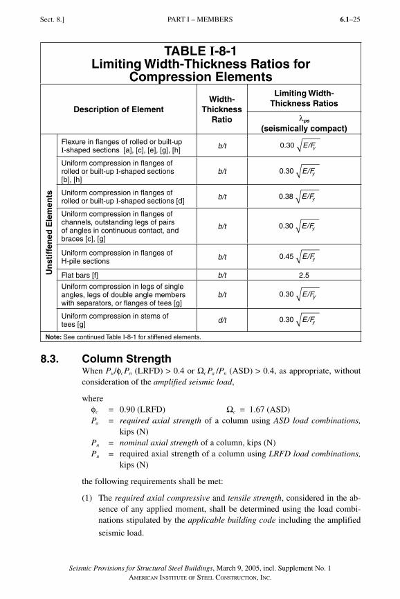
Seismic Provisions for Structural Steel Buildings, March 9, 2005, incl. Supplement No. 1AMERICAN INSTITUTE OF STEEL CONSTRUCTION, INC.
6.1–25
TABLE I-8-1Limiting Width-Thickness Ratios for
Compression Elements
Description of ElementWidth-
ThicknessRatio
Limiting Width-Thickness Ratios
λps
(seismically compact)
Un
stif
fen
ed E
lem
ents
Flexure in flanges of rolled or built-up I-shaped sections [a], [c], [e], [g], [h] b/t 0.30 E/Fy
Uniform compression in flanges of rolled or built-up I-shaped sections [b], [h]
b/t 0.30 E/Fy
Uniform compression in flanges of rolled or built-up I-shaped sections [d] b/t 0.38 E/Fy
Uniform compression in flanges of channels, outstanding legs of pairs of angles in continuous contact, and braces [c], [g]
b/t 0.30 E/Fy
Uniform compression in flanges of H-pile sections b/t 0.45 E/Fy
Flat bars [f] b/t 2.5
Uniform compression in legs of single angles, legs of double angle members with separators, or flanges of tees [g]
b/t 0.30 E/Fy
Uniform compression in stems of tees [g] d/t 0.30 E/Fy
Note: See continued Table I-8-1 for stiffened elements.
8.3. Column Strength When Pu/φcPn (LRFD) > 0.4 or ΩcPa /Pn (ASD) > 0.4, as appropriate, without consideration of the amplified seismic load,
whereφc = 0.90 (LRFD) Ωc = 1.67 (ASD)Pa = required axial strength of a column using ASD load combinations,
kips (N)Pn = nominal axial strength of a column, kips (N)Pu = required axial strength of a column using LRFD load combinations,
kips (N)
the following requirements shall be met:
(1) The required axial compressive and tensile strength, considered in the ab-sence of any applied moment, shall be determined using the load combi-nations stipulated by the applicable building code including the amplified
seismic load.
Sect. 8.] PART I – MEMBERS
SeismicProv1.indd 25SeismicProv1.indd 25 9/8/06 3:59:16 PM9/8/06 3:59:16 PMProcess BlackProcess Black
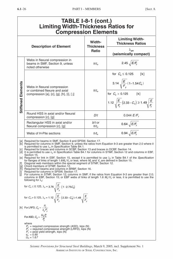
6.1–26
TABLE I-8-1 (cont.)Limiting Width-Thickness Ratios for
Compression Elements
Description of ElementWidth-
ThicknessRatio
Limiting Width-Thickness Ratios
λps
(seismically compact)
Sti
ffen
ed E
lem
ents
Webs in flexural compression in beams in SMF, Section 9, unless noted otherwise
h/tw 2.45 E/Fy
Webs in flexural compression or combined flexure and axial compression [a], [c], [g], [h], [i], [ j]
h/tw
for [k]C
EF
C
a
ya
≤
( )
0.125
3.14 1−1.54
E
Fy
≥ 1.49
for [k]C
E
F
a
ya
>
( )
0.125
1.12 2.33 −C
Round HSS in axial and/or flexural compression [c], [g] D/t 0.044 E /Fy
Rectangular HSS in axial and/or flexural compression [c], [g]
b/t orh/tw
0.64 E/Fy
Webs of H-Pile sections h/tw 0.94 E/Fy
[a] Required for beams in SMF, Section 9 and SPSW, Section 17.[b] Required for columns in SMF, Section 9, unless the ratios from Equation 9-3 are greater than 2.0 where it
is permitted to use λp in Specification Table B4.1. [c] Required for braces and columns in SCBF, Section 13 and braces in OCBF, Section 14.[d] It is permitted to use λp in Specification Table B4.1 for columns in STMF, Section 12 and columns in EBF,
Section 15.[e] Required for link in EBF, Section 15, except it is permitted to use λp in Table B4.1 of the Specification
for flanges of links of length 1.6Mp /Vp or less, where Mp and Vp are defined in Section 15.[f] Diagonal web members within the special segment of STMF, Section 12.[g] Chord members of STMF, Section 12.[h] Required for beams and columns in BRBF, Section 16.[i] Required for columns in SPSW, Section 17.[j] For columns in STMF, Section 12; columns in SMF, if the ratios from Equation 9-3 are greater than 2.0;
columns in EBF, Section 15; or EBF webs of links of length 1.6 Mp /Vp or less, it is permitted to use the following for λp:
for Ca ≤ 0.125, λp = E
Fya( )3.76 1−2.75C
for Ca > 0.125, λp = E
Fya( )1.12 E
Fy
≥1.492.33−C
[k] For LRFD, CP
Pau
b y
=φ
P
Py
ΩFor ASD, Ca
b a=
where Pa = required compressive strength (ASD), kips (N)Pu = required compressive strength (LRFD), kips (N)Py = axial yield strength, kips (N)φb = 0.90Ωb = 1.67
Seismic Provisions for Structural Steel Buildings, March 9, 2005, incl. Supplement No. 1AMERICAN INSTITUTE OF STEEL CONSTRUCTION, INC.
PART I – MEMBERS [Sect. 8.
SeismicProv1.indd 26SeismicProv1.indd 26 1/9/08 2:51:46 PM1/9/08 2:51:46 PM
6.1–27
(2) The required axial compressive and tensile strength shall not exceed either of the foll owing:
(a) The maximum load transferred to the column con sidering 1.1Ry (LRFD) or (1.1/1.5)Ry (ASD), as appropriate, times the nominal strengths of the connecting beam or brace elements of the building.
(b) The limit as deter mined from the resistance of the found ation to over-turning uplift.
8.4. Column Splices
8.4a. GeneralThe required strength of column splices in the seismic load resisting system (SLRS) shall equal the required strength of the columns, including that deter-mined from Sections 8.3, 9.9, 10.9, 11.9, 13.5 and 16.5b.
In addition, welded column splices that are subject to a calculated net tensile load effect determined using the load combinations stipulated by the applicable building code including the amplified seismic load, shall satisfy both of the fol-lowing requirements:
(1) The available strength of partial-joint-penetration (PJP) groove welded joints, if used, shall be at least equal to 200 percent of the required strength.
(2) The available strength for each flange splice shall be at least equal to 0.5 RyFyAf (LRFD) or (0.5/1.5)RyFyAf (ASD), as appropriate, where RyFy is the expected yield stress of the column material and Af is the flange area of the smaller column connected.
Beveled transitions are not required when changes in thickness and width of flanges and webs occur in column splices where PJP groove welded joints are used.
Column web splices shall be either bolted or welded, or welded to one column and bolted to the other. In moment frames using bolted splices, plates or channels shall be used on both sides of the column web.
The centerline of column splices made with fillet welds or partial-joint-penetra-tion groove welds shall be located 4 ft (1.2 m) or more away from the beam-to-column connections. When the column clear height between beam-to-column connections is less than 8 ft (2.4 m), splices shall be at half the clear height.
8.4b. Columns Not Part of the Seismic Load Resisting SystemSplices of columns that are not a part of the SLRS shall satisfy the following:
(1) Splices shall be located 4 ft (1.2 m) or more away from the beam-to-column connections. When the column clear height between beam-to-column connections is less than 8 ft (2.4 m), splices shall be at half the clear height.
Seismic Provisions for Structural Steel Buildings, March 9, 2005, incl. Supplement No. 1AMERICAN INSTITUTE OF STEEL CONSTRUCTION, INC.
PART I – MEMBERSSect. 8.]
SeismicProv1.indd 27SeismicProv1.indd 27 9/8/06 3:59:17 PM9/8/06 3:59:17 PMProcess BlackProcess Black
Seismic Provisions for Structural Steel Buildings, March 9, 2005, incl. Supplement No. 1AMERICAN INSTITUTE OF STEEL CONSTRUCTION, INC.
6.1–28
(2) The required shear strength of column splices with respect to both orthogonal axes of the column shall be Mpc /H (LRFD) or Mpc /1.5H (ASD), as appropriate, where Mpc is the lesser nominal plastic flexural strength of the column sections for the direction in question, and H is the story height.
8.5. Column BasesThe required strength of column bases shall be calculated in accordance with Sections 8.5a, 8.5b, and 8.5c. The available strength of anchor rods shall be determined in accordance with Specification Section J3.
The available strength of concrete elements at the column base, including anchor rod embedment and reinforcing steel, shall be in accordance with ACI 318, Appendix D.
User Note: When using concrete reinforcing steel as part of the anchorage embedment design, it is important to understand the anchor failure modes and provide reinforcement that is developed on both sides of the expected failure surface. See ACI 318, Appendix D, Figure RD.4.1 and Section D.4.2.1, in-cluding Commentary.
Exception: The special requirements in ACI 318, Appendix D, for “regions of moderate or high seismic risk, or for structures assigned to intermediate or high seismic performance or design categories” need not be applied.
8.5a Required Axial StrengthThe required axial strength of column bases, including their attachment to the foundation, shall be the summation of the vertical components of the required strengths of the steel elements that are connected to the column base.
8.5b. Required Shear StrengthThe required shear strength of column bases, including their attachments to the foundations, shall be the summation of the horizontal component of the required strengths of the steel elements that are connected to the column base asfollows:
(1) For diagonal bracing, the horizontal component shall be determined from the required strength of bracing connections for the seismic load resisting system (SLRS).
(2) For columns, the horizontal component shall be at least equal to the lesser of the following:
(a) 2Ry Fy Zx /H (LRFD) or (2/1.5) Ry Fy Zx /H (ASD), as appropriate, of the column
whereH = height of story, which may be taken as the distance between
the centerline of floor framing at each of the levels above and below, or the distance between the top of floor slabs at each of the levels above and below, in. (mm)
PART I – MEMBERS [Sect. 8.
SeismicProv1.indd 28SeismicProv1.indd 28 9/8/06 3:59:17 PM9/8/06 3:59:17 PMProcess BlackProcess Black
Seismic Provisions for Structural Steel Buildings, March 9, 2005, incl. Supplement No. 1AMERICAN INSTITUTE OF STEEL CONSTRUCTION, INC.
6.1–29
(b) The shear calculated using the load combinations of the applicable building code, including the amplified seismic load.
8.5c. Required Flexural StrengthThe required flexural strength of column bases, including their attachment to the foundation, shall be the summation of the required strengths of the steel elements that are connected to the column base as follows:
(1) For diagonal bracing, the required flexural strength shall be at least equal to the required strength of bracing connections for the SLRS.
(2) For columns, the required flexural strength shall be at least equal to the lesser of the following:
(a) 1.1Ry Fy Z (LRFD) or (1.1/1.5)Ry Fy Z (ASD), as appropriate, of the column or
(b) the moment calculated using the load combinations of the applicable building code, including the amplified seismic load.
8.6. H-Piles
8.6a. Design of H-PilesDesign of H-piles shall comply with the provisions of the Specification regard-ing design of members subjected to combined loads. H-piles shall meet the requirements of Section 8.2b.
8.6b. Battered H-PilesIf battered (sloped) and vertical piles are used in a pile group, the vertical piles shall be designed to support the combined effects of the dead and live loads without the participation of the battered piles.
8.6c. Tension in H-PilesTension in each pile shall be transferred to the pile cap by mechanical means such as shear keys, reinforcing bars or studs welded to the embedded portion of the pile. Directly below the bottom of the pile cap, each pile shall be free of attachments and welds for a length at least equal to the depth of the pile cross section.
9. SPECIAL MOMENT FRAMES (SMF)
9.1. Scope Special moment frames (SMF) are expected to withstand significant inelastic de-formations when subjected to the forces resulting from the motions of the design earthquake. SMF shall satisfy the requirements in this Section.
9.2. Beam-to-Column Connections
9.2a. RequirementsBeam-to-column connections used in the seismic load resisting system (SLRS) shall satisfy the following three requirements:
PART I – SPECIAL MOMENT FRAMESSect. 9.]
SeismicProv1.indd 29SeismicProv1.indd 29 9/8/06 3:59:18 PM9/8/06 3:59:18 PMProcess BlackProcess Black
Seismic Provisions for Structural Steel Buildings, March 9, 2005, incl. Supplement No. 1AMERICAN INSTITUTE OF STEEL CONSTRUCTION, INC.
6.1–30
(1) The connection shall be capable of sustaining an interstory drift angle of at least 0.04 radians.
(2) The measured flexural resistance of the connection, determined at the col-umn face, shall equal at least 0.80Mp of the connected beam at an interstory drift angle of 0.04 radians.
(3) The required shear strength of the connection shall be determined using the following quantity for the earthquake load effect E:
E = 2[1.1Ry Mp]/Lh (9-1)
whereRy = ratio of the expected yield stress to the specified minimum yield
stress, Fy
Mp = nominal plastic flexural strength, kip-in. (N-mm)Lh = distance between plastic hinge locations, in. (mm)
When E as defined in Equation 9-1 is used in ASD load combinations that are additive with other transient loads and that are based on SEI/ASCE 7, the 0.75 combination factor for transient loads shall not be applied to E.
Connections that accommodate the required interstory drift angle within the connection elements and provide the measured flexural resistance and shear strengths specified above are permitted. In addition to satisfying the require-ments noted above, the design shall demonstrate that any additional drift due to connection deformation can be accommodated by the structure. The design shall include analysis for stability effects of the overall frame, including second-order effects.
9.2b. Conformance DemonstrationBeam-to-column connections used in the SLRS shall satisfy the requirements of Section 9.2a by one of the following:
(a) Use of SMF connections designed in accordance with ANSI/AISC 358.
(b) Use of a connection prequalified for SMF in accordance with Appendix P.
(c) Provision of qualifying cyclic test results in accordance with Appendix S. Results of at least two cyclic connection tests shall be provided and are permitted to be based on one of the following:
(i) Tests reported in the research literature or documented tests performed for other projects that represent the project conditions, within the limits specified in Appendix S.
(ii) Tests that are conducted specifically for the project and are representa-tive of project member sizes, material strengths, connection configura-tions, and matching connection processes, within the limits specified in Appendix S.
PART I – SPECIAL MOMENT FRAMES [Sect. 9.
SeismicProv1.indd 30SeismicProv1.indd 30 9/8/06 3:59:18 PM9/8/06 3:59:18 PMProcess BlackProcess Black
Seismic Provisions for Structural Steel Buildings, March 9, 2005, incl. Supplement No. 1AMERICAN INSTITUTE OF STEEL CONSTRUCTION, INC.
6.1–31
9.2c. WeldsUnless otherwise designated by ANSI/AISC 358, or otherwise determined in a connection prequalification in accordance with Appendix P, or as determined in a program of qualification testing in accordance with Appendix S, complete-joint-penetration groove welds of beam flanges, shear plates, and beam webs to columns shall be demand critical welds as described in Section 7.3b.
User Note: For the designation of demand critical welds, standards such as ANSI/AISC 358 and tests addressing specific connections and joints should be used in lieu of the more general terms of these Provisions. Where these Provisions indicate that a particular weld is designated demand critical, but the more specific standard or test does not make such a designation, the more specific standard or test should govern. Likewise, these standards and tests may designate welds as demand critical that are not identified as such by these Provisions.
9.2d. Protected ZonesThe region at each end of the beam subject to inelastic straining shall be desig-nated as a protected zone, and shall meet the requirements of Section 7.4. The extent of the protected zone shall be as designated in ANSI/AISC 358, or as otherwise determined in a connection prequalification in accordance with Ap-pendix P, or as determined in a program of qualification testing in accordance with Appendix S.
User Note: The plastic hinging zones at the ends of SMF beams should be treated as protected zones. The plastic hinging zones should be established as part of a prequalification or qualification program for the connection, per Section 9.2b. In general, for unreinforced connections, the protected zone will extend from the face of the column to one half of the beam depth beyond the plastic hinge point.
9.3. Panel Zone of Beam-to-Column Connections (beam web parallel to column web)
9.3a. Shear Strength The required thickness of the panel zone shall be determined in accordance with the method used in proportioning the panel zone of the tested or prequalified connection. As a minimum, the required shear strength of the panel zone shall be determined from the summation of the moments at the column faces as de-termined by projecting the expected moments at the plastic hinge points to the column faces. The design shear strength shall be φvRv and the allowable shear strength shall be Rv/Ωv where
φv = 1.0 (LRFD) Ωv = 1.50 (ASD)
and the nominal shear strength, Rv, according to the limit state of shear yielding, is determined as specified in Specification Section J10.6.
PART I – SPECIAL MOMENT FRAMESSect. 9.]
SeismicProv1.indd 31SeismicProv1.indd 31 9/8/06 3:59:18 PM9/8/06 3:59:18 PMProcess BlackProcess Black
Seismic Provisions for Structural Steel Buildings, March 9, 2005, incl. Supplement No. 1AMERICAN INSTITUTE OF STEEL CONSTRUCTION, INC.
6.1–32
9.3b. Panel Zone ThicknessThe individual thicknesses, t, of column webs and doubler plates, if used, shall conform to the following requirement:
t � (dz + wz)/90 (9-2)where
t = thickness of column web or doubler plate, in. (mm)dz = panel zone depth between continuity plates, in. (mm)wz = panel zone width between column flanges, in. (mm)
Alternatively, when local buckling of the column web and doubler plate is pre-vented by using plug welds joining them, the total panel zone thickness shall satisfy Equation 9-2.
9.3c. Panel Zone Doubler Plates Doubler plates shall be welded to the column flanges using either a complete-joint-penetration groove-welded or fillet-welded joint that develops the available shear strength of the full doubler plate thickness. When doubler plates are placed against the column web, they shall be welded across the top and bottom edges to develop the proportion of the total force that is transmitted to the doubler plate. When doubler plates are placed away from the column web, they shall be placed symmetrically in pairs and welded to continuity plates to develop the proportion of the total force that is transmitted to the doubler plate.
9.4. Beam and Column Limi tationsThe requirements of Section 8.1 shall be satisfied, in addition to the following.
9.4a. Width-Thickness LimitationsBeam and column members shall meet the requirements of Section 8.2b, unless otherwise qualified by tests.
9.4b. Beam FlangesAbrupt changes in beam flange area are not permitted in plastic hinge regi ons. The drilling of flange holes or trimming of beam flange width is permitted if testing or qualification demonstrates that the resulting configuration can develop stable plastic hinges. The configuration shall be consistent with a prequalified connection designated in ANSI/AISC 358, or as otherwise determined in a connection prequalification in accordance with Appendix P, or in a program of qualification testing in accordance with Appendix S.
9.5. Continuity PlatesContinuity plates shall be consistent with the prequalified connection designated in ANSI/AISC 358, or as otherwise determined in a connection prequalification in accordance with Appendix P, or as determined in a program of qualification testing in accordance with Appendix S.
PART I – SPECIAL MOMENT FRAMES [Sect. 9.
SeismicProv1.indd 32SeismicProv1.indd 32 9/8/06 3:59:18 PM9/8/06 3:59:18 PMProcess BlackProcess Black
Seismic Provisions for Structural Steel Buildings, March 9, 2005, incl. Supplement No. 1AMERICAN INSTITUTE OF STEEL CONSTRUCTION, INC.
6.1–33
9.6. Column-Beam Moment RatioThe following relationship shall be satisfied at beam-to-column connections:
Σ
Σ
M
M
pc
pb
*
*.> 1 0 (9-3)
whereΣM*
pc = the sum of the moments in the column above and below the joint at the intersection of the beam and column centerlines. ΣM*
pc is deter-mined by summing the projections of the nominal flexural strengths of the columns (including haunches where used) above and below the joint to the beam centerline with a reduction for the axial force in the column. It is permitted to take ΣM*
pc = ΣZc(Fyc � Puc /Ag) (LRFD) or ΣZc[(Fyc /1.5) � Pac /Ag)] (ASD), as appropriate. When the cen-terlines of opposing beams in the same joint do not coincide, the mid-line between centerlines shall be used.
ΣM*pb = the sum of the moments in the beams at the intersection of the beam
and column centerlines. ΣM*pb is determined by summing the projec-
tions of the expected flexural strengths of the beams at the plas-tic hinge locations to the column centerline. It is permitted to take ΣM*
pb = Σ(1.1Ry Fyb Zb + Muv) (LRFD) or Σ[(1.1/1.5)Ry Fyb Zb + Mav] (ASD), as appropriate. Alternatively, it is permitted to determine ΣM*
pb consistent with a prequalified connection design as designat-ed in ANSI/AISC 358, or as otherwise determined in a connection prequalification in accordance with Appendix P, or in a program of qualification testing in accordance with Appendix S. When connec-tions with reduced beam sections are used, it is permitted to take ΣM*
pb = Σ(1.1Ry Fyb ZRBS + Muv) (LRFD) or Σ[(1.1/1.5)Ry Fyb ZRBS + Mav] (ASD), as appropriate.
Ag = gross area of column, in.2 (mm2)Fyc = specified minimum yield stress of column, ksi (MPa)Mav = the additional moment due to shear amplification from the location
of the plastic hinge to the column centerline, based on ASD load combinations, kip-in. (N-mm)
Muv = the additional moment due to shear amplification from the location of the plastic hinge to the column centerline, based on LRFD load combinations, kip-in. (N-mm)
Pac = required compressive strength using ASD load combinations, kips (a positive number) (N)
Puc = required compressive strength using LRFD load combinations, kips (a positive number) (N)
Zb = plastic section modulus of the beam, in.3 (mm3)Zc = plastic section modulus of the column, in.3 (mm3)ZRBS = minimum plastic section modulus at the reduced beam section,
in.3 (mm3)
PART I – SPECIAL MOMENT FRAMESSect. 9.]
SeismicProv1.indd 33SeismicProv1.indd 33 9/8/06 3:59:18 PM9/8/06 3:59:18 PMProcess BlackProcess Black
Seismic Provisions for Structural Steel Buildings, March 9, 2005, incl. Supplement No. 1AMERICAN INSTITUTE OF STEEL CONSTRUCTION, INC.
6.1–34
Exception: This requ irem ent does not apply if either of the following two condi-tions is satisfied:
(a) Columns with Prc < 0.3Pc for all load combinations other than those de-termined using the amplified seismic load that satisfy either of the following:
(i) Columns used in a one-story building or the top story of a multistory building.
(ii) Columns where: (1) the sum of the available shear strengths of all exempted columns in the story is less than 20 percent of the sum of the available shear strengths of all moment frame columns in the story acting in the same direction; and (2) the sum of the available shear strengths of all exempted columns on each moment frame column line within that story is less than 33 percent of the available shear strength of all moment frame columns on that column line. For the purpose of this exception, a column line is defined as a single line of columns or parallel lines of columns located within 10 percent of the plan dimen-sion perpendicular to the line of columns.
whereFor design according to Specification Section B3.3 (LRFD),
Pc = Fyc Ag, kips (N)Prc = Puc, required compressive strength, using LRFD load combina-
tions, kips (N)
For design according to Specification Section B3.4 (ASD),Pc = Fyc Ag /1.5, kips (N)Prc = Pac, required compressive strength, using ASD load combinations,
kips (N)
(b) Columns in any story that has a ratio of available shear strength to required shear strength that is 50 percent greater than the story above.
9.7. Lateral Bracing at Beam-to-Column Connections
9.7a. Braced ConnectionsColumn flanges at beam-to-column connections require lateral bracing only at the level of the top flanges of the beams, when the webs of the beams and col-umn are co-planar, and a column is shown to remain elastic outside of the panel zone. It shall be permitted to assume that the column remains elastic when the ratio calculated using Equation 9-3 is greater than 2.0.
When a column cannot be shown to remain elastic outside of the panel zone, the following requirements shall apply:
(1) The column flanges shall be laterally braced at the levels of both the top and bottom beam flanges. Lateral bracing shall be either direct or indirect.
PART I – SPECIAL MOMENT FRAMES [Sect. 9.
SeismicProv1.indd 34SeismicProv1.indd 34 9/8/06 3:59:19 PM9/8/06 3:59:19 PMProcess BlackProcess Black
Seismic Provisions for Structural Steel Buildings, March 9, 2005, incl. Supplement No. 1AMERICAN INSTITUTE OF STEEL CONSTRUCTION, INC.
6.1–35
User Note: Direct lateral support (bracing) of the column flange is achieved through use of braces or other members, deck and slab, attached to the col-umn flange at or near the desired bracing point to resist lateral buckling. Indirect lateral support refers to bracing that is achieved through the stiff-ness of members and connections that are not directly attached to the column flanges, but rather act through the column web or stiffener plates.
(2) Each column-flange lateral brace shall be designed for a required strength that is equal to 2 percent of the available beam flange strength Fy bf tbf (LRFD) or Fy bf tbf /1.5 (ASD), as appropriate.
9.7b. Unbraced Connections A column containing a beam-to-column conne ction with no lateral bracing trans-verse to the seismic frame at the connec tion shall be designed using the distance bet ween adjacent lateral braces as the column height for buckling transverse to the seismic frame and shall conform to Specification Chapter H, except that:
(1) The required column strength shall be determined from the appropriate load combinations in the applicable building code, except that E shall be taken as the lesser of:
(a) The amplified seismic load.
(b) 125 percent of the frame available strength based upon either the beam available flexural strength or panel zone available shear stre ngth.
(2) The slenderness L/r for the column shall not exceed 60.
(3) The column required flexural strength transverse to the seismic frame shall include that moment caused by the application of the beam flange force specified in Section 9.7a.(2) in addition to the second-order moment due to the resulting column flange dis placement.
9.8. Lateral Bracing of Beams Both flanges of beams shall be laterally braced, with a maximum spacing of Lb = 0.086ry E/Fy. Braces shall meet the provisions of Equations A-6-7 and A-6-8 of Appendix 6 of the Specification, where Mr = Mu = Ry ZFy (LRFD) or Mr = Ma = Ry ZFy /1.5 (ASD), as appropriate, of the beam and Cd = 1.0.
In addi tion, lateral braces shall be placed near concentrated forces, changes in cross-section, and other locations where analysis indicates that a plastic hinge will form during inelastic deformations of the SMF. The placement of lateral bracing shall be consistent with that documented for a prequalified connec-tion designated in ANSI/AISC 358, or as otherwise determined in a connection prequalification in accordance with Appendix P, or in a program of qualification testing in accordance with Appendix S.
PART I – SPECIAL MOMENT FRAMESSect. 9.]
SeismicProv1.indd 35SeismicProv1.indd 35 9/8/06 3:59:19 PM9/8/06 3:59:19 PMProcess BlackProcess Black
Seismic Provisions for Structural Steel Buildings, March 9, 2005, incl. Supplement No. 1AMERICAN INSTITUTE OF STEEL CONSTRUCTION, INC.
6.1–36
The required strength of lateral bracing provided adjacent to plastic hinges shall be Pu = 0.06 Mu /ho (LRFD) or Pa = 0.06Ma /ho (ASD), as appropriate, where ho is the distance between flange centroids; and the required stiffness shall meet the provisions of Equation A-6-8 of Appendix 6 of the Specification.
9.9. Column SplicesColumn splices shall comply with the requirements of Section 8.4a. Where groove welds are used to make the splice, they shall be complete-joint-penetra-tion groove welds that meet the requirements of Section 7.3b. Weld tabs shall be removed. When column splices are not made with groove welds, they shall have a required flexural strength that is at least equal to Ry Fy Zx (LRFD) or Ry Fy Zx /1.5 (ASD), as appropriate, of the smaller column. The required shear strength of column web splices shall be at least equal to ΣMpc /H (LRFD) or ΣMpc /1.5H (ASD), as appropriate, where ΣMpc is the sum of the nominal plastic flexural strengths of the columns above and below the splice.
Exception: The required strength of the column splice considering appropriate stress concentration factors or fracture mechanics stress intensity factors need not exceed that determined by inelastic analyses.
10. INTERMEDIATE MOMENT FRAMES (IMF)
10.1. ScopeIntermediate moment frames (IMF) are expected to withstand limited inelastic deformations in their members and connections when subjected to the forces resulting from the motions of the design earthquake. IMF shall meet the require-ments in this Section.
10.2. Beam-to-Column Connections
10.2a. RequirementsBeam-to-column connections used in the seismic load resisting system (SLRS) shall satisfy the requirements of Section 9.2a, with the following exceptions:
(1) The required interstory drift angle shall be a minimum of 0.02 radian.
(2) The required strength in shear shall be determined as specified in Section 9.2a, except that a lesser value of Vu or Va, as appropriate, is permitted if justified by analysis. The required shear strength need not exceed the shear resulting from the application of appropriate load combinations in the applicable building code using the amplified seismic load.
10.2b. Conformance DemonstrationConformance demonstration shall be as described in Section 9.2b to satisfy the requirements of Section 10.2a for IMF, except that a connection prequalified for IMF in accordance with ANSI/AISC 358, or as otherwise determined in a con-nection prequalification in accordance with Appendix P, or as determined in a program of qualification testing in accordance with Appendix S.
PART I – SPECIAL MOMENT FRAMES [Sect. 9.
SeismicProv1.indd 36SeismicProv1.indd 36 9/8/06 3:59:19 PM9/8/06 3:59:19 PMProcess BlackProcess Black
Seismic Provisions for Structural Steel Buildings, March 9, 2005, incl. Supplement No. 1AMERICAN INSTITUTE OF STEEL CONSTRUCTION, INC.
6.1–37
10.2c. WeldsUnless otherwise designated by ANSI/AISC 358, or otherwise determined in a connection prequalification in accordance with Appendix P, or as determined in a program of qualification testing in accordance with Appendix S, complete-joint-penetration groove welds of beam flanges, shear plates, and beam webs to columns shall be demand critical welds as described in Section 7.3b.
User Note: For the designation of demand critical welds, standards such as ANSI/AISC 358 and tests addressing specific connections and joints should be used in lieu of the more general terms of these Provisions. Where these Provisions indicate that a particular weld is designated demand critical, but the more specific standard or test does not make such a designation, the more specific standard or test should govern. Likewise, these standards and tests may designate welds as demand critical that are not identified as such by these Provisions.
10.2d. Protected ZoneThe region at each end of the beam subject to inelastic straining shall be treated as a protected zone, and shall meet the requirements of Section 7.4. The extent of the protected zone shall be as designated in ANSI/AISC 358, or as other-wise determined in a connection prequalification in accordance with Appen-dix P, or as determined in a program of qualification testing in accordance with Appendix S.
User Note: The plastic hinging zones at the ends of IMF beams should be treated as protected zones. The plastic hinging zones should be established as part of a prequalification or qualification program for the connection. In general, for unreinforced connections, the protected zone will extend from the face of the column to one half of the beam depth beyond the plastic hinge point.
10.3. Panel Zone of Beam-to-Column Connections (beam web parallel to column web)No additional requirements beyond the Specification.
10.4. Beam and Column LimitationsThe requirements of Section 8.1 shall be satisfied, in addition to the following.
10.4a. Width-Thickness LimitationsBeam and column members shall meet the requirements of Section 8.2a, unless otherwise qualified by tests.
10.4b. Beam FlangesAbrupt changes in beam flange area are not permitted in plastic hinge regi ons. Drilling of flange holes or trimming of beam flange width is permitted if testing or qualification demonstrates that the resulting configuration can develop stable plastic hinges. The configuration shall be consistent with a prequalified connection
PART I – INTERMEDIATE MOMENT FRAMESSect. 10.]
SeismicProv1.indd 37SeismicProv1.indd 37 9/8/06 3:59:19 PM9/8/06 3:59:19 PMProcess BlackProcess Black
Seismic Provisions for Structural Steel Buildings, March 9, 2005, incl. Supplement No. 1AMERICAN INSTITUTE OF STEEL CONSTRUCTION, INC.
6.1–38
designated in ANSI/AISC 358, or as otherwise determined in a connection prequalification in accordance with Appendix P, or in a program of qualification testing in accordance with Appendix S.
10.5. Continuity PlatesContinuity plates shall be provided to be consistent with the prequalified connec-tions designated in ANSI/AISC 358, or as otherwise determined in a connection prequalification in accordance with Appendix P, or as determined in a program of qualification testing in accordance with Appendix S.
10.6. Column-Beam Moment RatioNo additional requirements beyond the Specification.
10.7. Lateral Bracing at Beam-to-Column ConnectionsNo additional requirements beyond the Specification.
10.8. Lateral Bracing of BeamsBoth flanges shall be laterally braced directly or indirectly. The unbraced length between lateral braces shall not exceed 0.17ry E/Fy. Braces shall meet the provi-sions of Equations A-6-7 and A-6-8 of Appendix 6 of the Specification, where Mr = Mu = Ry Z Fy (LRFD) or Mr = Ma = Ry Z Fy /1.5 (ASD), as appropriate, of the beam, and Cd = 1.0.
In addi tion, lateral braces shall be placed near concentrated loads, changes in cross-section and other locations where analysis indicates that a plastic hinge will form during inelastic deformations of the IMF. Where the design is based upon assemblies tested in accordance with Appendix S, the placement of lateral bracing for the beams shall be consistent with that used in the tests or as required for prequalification in Appendix P. The required strength of lateral bracing pro-vided adjacent to plastic hinges shall be Pu = 0.06 Mu /ho (LRFD) or Pa = 0.06Ma /ho (ASD), as appropriate, where ho = distance between flange centroids; and the required stiffness shall meet the provisions of Equation A-6-8 of Appendix 6 of the Specification.
10.9. Column SplicesColumn splices shall comply with the requirements of Section 8.4a. Where groove welds are used to make the splice, they shall be complete-joint-penetra-tion groove welds that meet the requirements of Section 7.3b.
11. ORDINARY MOMENT FRAMES (OMF)
11.1. ScopeOrdinary moment frames (OMF) are expected to withstand minimal inelastic deformations in their members and connections when subjected to the forces resulting from the motions of the design earthquake. OMF shall meet the requirements of this Section. Connections in conformance with Sections 9.2b and 9.5 or Sections 10.2b and 10.5 shall be permitted for use in OMF without meeting the requirements of Sections 11.2a, 11.2c, and 11.5.
PART I – INTERMEDIATE MOMENT FRAMES [Sect. 10.
SeismicProv1.indd 38SeismicProv1.indd 38 9/8/06 3:59:20 PM9/8/06 3:59:20 PMProcess BlackProcess Black
Seismic Provisions for Structural Steel Buildings, March 9, 2005, incl. Supplement No. 1AMERICAN INSTITUTE OF STEEL CONSTRUCTION, INC.
6.1–39
User Note: While these provisions for OMF were primarily developed for use with wide flange shapes, with judgment, they may also be applied to other shapes such as channels, built-up sections, and hollow structural sections (HSS).
11.2. Beam-to-Column ConnectionsBeam-to-column connections shall be made with welds and/or high-strength bolts. Connections are permitted to be fully restrained (FR) or partially restrained (PR) moment connections as follows.
11.2a. Requirements for FR Moment ConnectionsFR moment connections that are part of the seismic load resisting system (SLRS) shall be designed for a required flexural strength that is equal to 1.1Ry Mp (LRFD) or (1.1/1.5)Ry Mp (ASD), as appropriate, of the beam or girder, or the maximum moment that can be developed by the system, whichever is less.
FR connections shall meet the following requirements.
(1) Where steel backing is used in connections with complete-joint-penetration (CJP) beam flange groove welds, steel backing and tabs shall be removed, except that top-flange backing attached to the column by a continuous fillet weld on the edge below the CJP groove weld need not be removed. Removal of steel backing and tabs shall be as follows:
(i) Following the removal of backing, the root pass shall be backgouged to sound weld metal and backwelded with a reinforcing fillet. The rein-forcing fillet shall have a minimum leg size of c in. (8 mm).
(ii) Weld tab removal shall extend to within 8 in. (3 mm) of the base metal surface, except at continuity plates where removal to within ¼ in. (6 mm) of the plate edge is acceptable. Edges of the weld tab shall be finished to a surface roughness value of 500 μin. (13 μm) or better. Grinding to a flush condition is not required. Gouges and notches are not permit-ted. The transitional slope of any area where gouges and notches have been removed shall not exceed 1:5. Material removed by grinding that extends more than z in. (2 mm) below the surface of the base metal shall be filled with weld metal. The contour of the weld at the ends shall provide a smooth transition, free of notches and sharp corners.
(2) Where weld access holes are provided, they shall be as shown in Figure 11-1. The weld access hole shall have a surface roughness value not to exceed 500 μin. (13 μm), and shall be free of notches and gouges. Notches and gouges shall be repaired as required by the engineer of record. Weld access holes are prohibited in the beam web adjacent to the end-plate in bolted moment end-plate connections.
(3) The required strength of double-sided partial-joint-penetration groove welds and double-sided fillet welds that resist tensile forces in connec-tions shall be 1.1Ry Fy Ag (LRFD) or (1.1/1.5)Ry Fy Ag (ASD), as appropriate, of the connected element or part. Single-sided partial-joint-penetration
PART I – ORDINARY MOMENT FRAMESSect. 11.]
SeismicProv1.indd 39SeismicProv1.indd 39 9/8/06 3:59:20 PM9/8/06 3:59:20 PMProcess BlackProcess Black
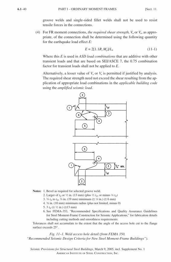
Seismic Provisions for Structural Steel Buildings, March 9, 2005, incl. Supplement No. 1AMERICAN INSTITUTE OF STEEL CONSTRUCTION, INC.
6.1–40
groove welds and single-sided fillet welds shall not be used to resist tensile forces in the connections.
(4) For FR moment connections, the required shear strength, Vu or Va, as appro-priate, of the connection shall be determined using the following quantity for the earthquake load effect E:
E = 2[1.1Ry Mp]/Lh (11-1)
Where this E is used in ASD load combinations that are additive with other transient loads and that are based on SEI/ASCE 7, the 0.75 combination factor for transient loads shall not be applied to E.
Alternatively, a lesser value of Vu or Va is permitted if justified by analysis. The required shear strength need not exceed the shear resulting from the ap-plication of appropriate load combinations in the applicable building code using the amplified seismic load.
Notes: 1. Bevel as required for selected groove weld. 2. Larger of tbf or 2 in. (13 mm) (plus 2 tbf, or minus 4 tbf) 3. w tbf to tbf, w in. (19 mm) minimum (± 4 in.) (± 6 mm) 4. a in. (10 mm) minimum radius (plus not limited, minus 0) 5. 3 tbf (± 2 in.) (±13 mm) 6. See FEMA-353, “Recommended Specifications and Quality Assurance Guidelines
for Steel Moment-Frame Construction for Seismic Applications,” for fabrication details including cutting methods and smoothness requirements.
Tolerances shall not accumulate to the extent that the angle of the access hole cut to the flange surface exceeds 25°.
Fig. 11–1. Weld access hole detail (from FEMA 350, “Recommended Seismic Design Criteria for New Steel Moment-Frame Buildings”).
PART I – ORDINARY MOMENT FRAMES [Sect. 11.
SeismicProv1.indd 40SeismicProv1.indd 40 1/9/08 3:52:25 PM1/9/08 3:52:25 PM
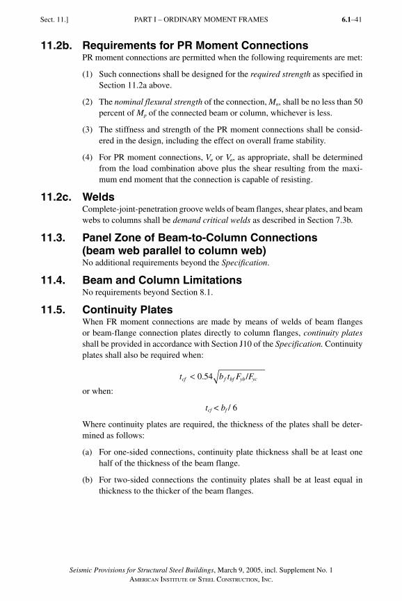
Seismic Provisions for Structural Steel Buildings, March 9, 2005, incl. Supplement No. 1AMERICAN INSTITUTE OF STEEL CONSTRUCTION, INC.
6.1–41
11.2b. Requirements for PR Moment ConnectionsPR moment connections are permitted when the following requirements are met:
(1) Such connections shall be designed for the required strength as specified in Section 11.2a above.
(2) The nominal flexural strength of the connection, Mn, shall be no less than 50 percent of Mp of the connected beam or column, whichever is less.
(3) The stiffness and strength of the PR moment connections shall be consid-ered in the design, including the effect on overall frame stability.
(4) For PR moment connections, Vu or Va, as appropriate, shall be determined from the load combination above plus the shear resulting from the maxi-mum end moment that the connection is capable of resisting.
11.2c. WeldsComplete-joint-penetration groove welds of beam flanges, shear plates, and beam webs to columns shall be demand critical welds as described in Section 7.3b.
11.3. Panel Zone of Beam-to-Column Connections (beam web parallel to column web)No additional requirements beyond the Specification.
11.4. Beam and Column LimitationsNo requirements beyond Section 8.1.
11.5. Continuity PlatesWhen FR moment connections are made by means of welds of beam flanges or beam-flange connection plates directly to column flanges, continuity plates shall be provided in accordance with Section J10 of the Specification. Continuity plates shall also be required when:
t b t F Fcf f bf yb yc< 0 54. /
or when:
tcf < bf / 6
Where continuity plates are required, the thickness of the plates shall be deter-mined as follows:
(a) For one-sided connections, continuity plate thickness shall be at least one half of the thickness of the beam flange.
(b) For two-sided connections the continuity plates shall be at least equal in thickness to the thicker of the beam flanges.
PART I – ORDINARY MOMENT FRAMESSect. 11.]
SeismicProv1.indd 41SeismicProv1.indd 41 9/8/06 3:59:21 PM9/8/06 3:59:21 PMProcess BlackProcess Black
Seismic Provisions for Structural Steel Buildings, March 9, 2005, incl. Supplement No. 1AMERICAN INSTITUTE OF STEEL CONSTRUCTION, INC.
6.1–42
The welded joints of the continuity plates to the column flanges shall be made with either complete-joint-penetration groove welds, two-sided partial-joint-penetration groove welds combined with reinforcing fillet welds, or two-sided fillet welds. The required strength of these joints shall not be less than the available strength of the contact area of the plate with the column flange. The required strength of the welded joints of the continuity plates to the column web shall be the least of the following:
(a) The sum of the available strengths at the connections of the continuity plate to the column flanges.
(b) The available shear strength of the contact area of the plate with the column web.
(c) The weld available strength that develops the available shear strength of the column panel zone.
(d) The actual force transmitted by the stiffener.
11.6. Column-Beam Moment RatioNo requirements.
11.7. Lateral Bracing at Beam-to-Column Connections No additional requirements beyond the Specification.
11.8. Lateral Bracing of BeamsNo additional requirements beyond the Specification.
11.9. Column SplicesColumn splices shall comply with the requirements of Section 8.4a.
12. SPECIAL TRUSS MOMENT FRAMES (STMF)
12.1. ScopeSpecial truss moment frames (STMF) are expected to withstand significant in-elastic deformation within a specially designed segment of the truss when sub-jected to the forces from the motions of the design earthquake. STMF shall be limited to span lengths between columns not to exceed 65 ft (20 m) and overall depth not to exceed 6 ft (1.8 m). The columns and truss segments outside of the special segments shall be designed to remain elastic under the forces that can be generated by the fully yielded and strain-hardened special segment. STMF shall meet the requirements in this Section.
12.2. Special SegmentEach horizontal truss that is part of the seismic load resisting system (SLRS) shall have a special segment that is located between the quarter points of the span of the truss. The length of the special segment shall be between 0.1 and 0.5 times the truss span length. The length-to-depth ratio of any panel in the special seg-ment shall neither exceed 1.5 nor be less than 0.67.
PART I – ORDINARY MOMENT FRAMES [Sect. 11.
SeismicProv1.indd 42SeismicProv1.indd 42 9/8/06 3:59:21 PM9/8/06 3:59:21 PMProcess BlackProcess Black
Seismic Provisions for Structural Steel Buildings, March 9, 2005, incl. Supplement No. 1AMERICAN INSTITUTE OF STEEL CONSTRUCTION, INC.
6.1–43
Panels within a special segment shall either be all Vierendeel panels or all X-braced panels; neither a combination thereof nor the use of other truss diagonal configurations is permitted. Where diagonal members are used in the special segment, they shall be arranged in an X pattern separated by vertical members. Such diagonal members shall be interconnected at points where they cross. The interconnection shall have a required strength equal to 0.25 times the nominal tensile strength of the diagonal member. Bolted connections shall not be used for web members within the special segment. Diagonal web members within the special segment shall be made of flat bars of identical sections.
Splicing of chord members is not permitted within the special segment, nor with-in one-half the panel length from the ends of the special segment. The required axial strength of the diagonal web members in the special segment due to dead and live loads within the special segment shall not exceed 0.03Fy Ag (LRFD) or (0.03/1.5)Fy Ag (ASD), as appropriate.
The special segment shall be a protected zone meeting the requirements of Section 7.4.
12.3. Strength of Special Segment MembersThe available shear strength of the special segment shall be calculated as the sum of the available shear strength of the chord members through flexure, and the shear strength corresponding to the available tensile strength and 0.3 times the available compressive strength of the diagonal members, when they are used. The top and bottom chord members in the special segment shall be made of iden-tical sections and shall provide at least 25 percent of the required vertical shear strength. The required axial strength in the chord members, determined accord-ing to the limit state of tensile yielding, shall not exceed 0.45 times φPn (LRFD) or Pn / Ω (ASD), as appropriate,
φ = 0.90 (LRFD) Ω = 1.67 (ASD)
wherePn = Fy A g
The end connection of diagonal web members in the special segment shall have a required strength that is at least equal to the expected yield strength, in tension, of the web member, Ry Fy Ag (LRFD) or Ry Fy Ag / 1.5 (ASD), as appropriate.
12.4. Strength of Non-Special Segment MembersMembers and connections of STMF, except those in the special segment speci-fied in Section 12.2, shall have a required strength based on the appropriate load combinations in the applicable building code, replacing the earthquake load term E with the lateral loads necessary to develop the expected vertical shear strength of the special segment Vne (LRFD) or Vne /1.5 (ASD), as appropriate, at mid-length, given as:
VR M
LEI
L L
LR P Pne
y nc
s
s
sy nt= +
−( )+ +
3 750 075 0 3
3
.. . nnc( )sin α (12-1)
PART I – SPECIAL TRUSS MOMENT FRAMESSect. 12.]
SeismicProv1.indd 43SeismicProv1.indd 43 9/8/06 3:59:21 PM9/8/06 3:59:21 PMProcess BlackProcess Black
Seismic Provisions for Structural Steel Buildings, March 9, 2005, incl. Supplement No. 1AMERICAN INSTITUTE OF STEEL CONSTRUCTION, INC.
6.1–44
whereMnc = nominal flexural strength of a chord member of the special segment,
kip-in. (N-mm)EI = flexural elastic stiffness of a chord member of the special segment,
kip-in.2 (N-mm2)L = span length of the truss, in. (mm)Ls = length of the special segment, in. (mm)Pnt = nominal tensile strength of a diagonal member of the special
segment, kips (N)Pnc = nominal compressive strength of a diagonal member of the special
segment, kips (N)α = angle of diagonal members with the horizontal
12.5. Width-Thickness LimitationsChord members and diagonal web members within the special segment shall meet the requirements of Section 8.2b.
12.6. Lateral BracingThe top and bottom chords of the trusses shall be laterally braced at the ends of the special segment, and at intervals not to exceed Lp according to Specification Chapter F, along the entire length of the truss. The required strength of each lateral brace at the ends of and within the special segment shall be
Pu = 0.06 Ry Pnc (LRFD) or Pa = (0.06/1.5) Ry Pnc (ASD), as appropriate,
where Pnc is the nominal compressive strength of the special segment chord member.
Lateral braces outside of the special segment shall have a required strength of
Pu = 0.02 Ry Pnc (LRFD) orPa = (0.02/1.5) Ry Pnc (ASD), as appropriate.
The required brace stiffness shall meet the provisions of Equation A-6-4 of Appendix 6 of the Specification, where
Pr = Pu = Ry Pnc (LRFD) orPr = Pa = Ry Pnc /1.5 (ASD), as appropriate.
13. SPECIAL CONCENTRICALLY BRACED FRAMES (SCBF)
13.1. ScopeSpecial concentrically braced frames (SCBF) are expected to withstand signifi-cant inelastic deformations when subjected to the forces resulting from the motions of the design earthquake. SCBF shall meet the requirements in this Section.
PART I – SPECIAL TRUSS MOMENT FRAMES [Sect. 12.
SeismicProv1.indd 44SeismicProv1.indd 44 9/8/06 3:59:21 PM9/8/06 3:59:21 PMProcess BlackProcess Black
Seismic Provisions for Structural Steel Buildings, March 9, 2005, incl. Supplement No. 1AMERICAN INSTITUTE OF STEEL CONSTRUCTION, INC.
6.1–45
User Note: Section 14 (OCBF) should be used for the design of tension-only bracing.
13.2. Members
13.2a. Slenderness
Bracing members shall have Kl r E Fy/ /≤ 4 .
Exception: Braces with 4 200E/F Kl/ry < ≤ are permitted in frames in which the available strength of the column is at least equal to the maximum load trans-ferred to the column con sidering Ry (LRFD) or (1/1.5)Ry (ASD), as appropriate, times the nominal strengths of the connecting brace elements of the building. Column forces need not exceed those determined by inelastic analysis, nor the maximum load effects that can be developed by the system.
13.2b. Required Strength Where the effective net area of bracing members is less than the gross area, the required tensile strength of the brace based upon the limit state of fracture in the net section shall be greater than the lesser of the following:
(a) The expected yield strength, in tension, of the bracing member, determined as Ry Fy Ag (LRFD) or Ry Fy Ag /1.5 (ASD), as appropriate.
(b) The maximum load effect, indicated by analysis that can be trans ferred to the brace by the system.
User Note: This provision applies to bracing members where the section is reduced. A typical case is a slotted HSS brace at the gusset plate connection.
13.2c. Lateral Force Distribution Along any line of bracing, braces shall be deployed in alternate directions such that, for either direction of force parallel to the bracing, at least 30 percent but no more than 70 percent of the total horizontal force along that line is resisted by braces in tension, unless the available strength of each brace in compression is larger than the required strength resulting from the application of the appropri-ate load combinations stipulated by the applicable building code including the amplified seismic load. For the purposes of this provision, a line of brac ing is defined as a single line or parallel lines with a plan offset of 10 percent or less of the building dimension per pendicular to the line of brac ing.
13.2d. Width-Thickness LimitationsColumn and brace members shall meet the requirements of Section 8.2b.
User Note: HSS walls may be stiffened to comply with this requirement.
PART I – SPECIAL CONCENTRICALLY BRACED FRAMESSect. 13.]
SeismicProv1.indd 45SeismicProv1.indd 45 9/8/06 3:59:22 PM9/8/06 3:59:22 PMProcess BlackProcess Black
Seismic Provisions for Structural Steel Buildings, March 9, 2005, incl. Supplement No. 1AMERICAN INSTITUTE OF STEEL CONSTRUCTION, INC.
6.1–46
13.2e. Built-up Members The spacing of stitches shall be such that the slenderness ratio l/r of individual elements between the stitches does not exceed 0.4 times the governing slender-ness ratio of the built-up member.
The sum of the available shear strengths of the stitches shall equal or exceed the available tensile strength of each element. The spacing of stitches shall be uni-form. Not less than two stitches shall be used in a built-up member. Bolted stitch-es shall not be located within the middle one-fourth of the clear brace length.
Exception: Where the buckling of braces about their critical bucking axis does not cause shear in the stitches, the spacing of the stitches shall be such that the slenderness ratio l/r of the individual elements between the stitches does not exceed 0.75 times the governing slenderness ratio of the built-up member.
13.3. Required Strength of Bracing Connections
13.3a. Required Tensile Strength The required tensile strength of bracing connections (including beam- to-column connections if part of the bracing system) shall be the lesser of the following:
(a) The expected yield strength, in tension, of the bracing member, determined as Ry Fy Ag (LRFD) or Ry Fy Ag /1.5 (ASD), as appropriate.
(b) The maximum load effect, indicated by analysis that can be trans ferred to the brace by the system.
13.3b. Required Flexural Strength The required flexural strength of bracing connections shall be equal to 1.1Ry Mp (LRFD) or (1.1/1.5)Ry Mp (ASD), as appropriate, of the brace about the critical buckling axis.
Exception: Brace connections that meet the requirements of Section 13.3a and can accommodate the inelastic rotations associated with brace post-buckling deformations need not meet this requirement.
User Note: Accommodation of inelastic rotation is typically accomplished by means of a single gusset plate with the brace terminating before the line of restraint. The detailing requirements for such a connection are described in the commentary.
13.3c. Required Compressive StrengthBracing connections shall be designed for a required compressive strength based on buckling limit states that is at least equal to 1.1RyPn (LRFD) or (1.1/1.5)RyPn (ASD), as appropriate, where Pn is the nominal compressive strength of the brace.
PART I – SPECIAL CONCENTRICALLY BRACED FRAMES [Sect. 13.
SeismicProv1.indd 46SeismicProv1.indd 46 9/8/06 3:59:22 PM9/8/06 3:59:22 PMProcess BlackProcess Black
Seismic Provisions for Structural Steel Buildings, March 9, 2005, incl. Supplement No. 1AMERICAN INSTITUTE OF STEEL CONSTRUCTION, INC.
6.1–47
13.4. Special Bracing Conf igur ation Requirements
13.4a. V-Type and Inverted-V-Type Bracing V-type and inverted V-type SCBF shall meet the following requirements:
(1) The required strength of beams intersected by braces, their connections, and supporting members shall be determined based on the load combinations of the applicable building code assuming that the braces provide no support for dead and live loads. For load combinations that include earthquake ef-fects, the earthquake effect, E, on the beam shall be determined as follows:
(a) The forces in all braces in tension shall be assumed to be equal to Ry Fy Ag.
(b) The forces in all adjoining braces in compression shall be assumed to be equal to 0.3Pn.
(2) Beams shall be continuous between columns. Both flanges of beams shall be laterally braced, with a maximum spacing of Lb = Lpd, as specified by Equation A-1-7 and A-1-8 of Appendix 1 of the Specification. Lateral brac-es shall meet the provisions of Equations A-6-7 and A-6-8 of Appendix 6 of the Specification, where Mr = Mu = Ry Z Fy (LRFD) or Mr = Ma = Ry Z Fy /1.5 (ASD), as appropriate, of the beam and Cd = 1.0.
As a minimum, one set of lateral braces is required at the point of intersection of the V-type (or inverted V-type) bracing, unless the beam has sufficient out-of-plane strength and stiffness to ensure stability between adjacent brace points.
User Note: One method of demonstrating sufficient out-of-plane strength and stiffness of the beam is to apply the bracing force defined in Equation A-6-7 of Appendix 6 of the Specification to each flange so as to form a torsional couple; this loading should be in conjunction with the flexural forces de-fined in item (1) above. The stiffness of the beam (and its restraints) with re-spect to this torsional loading should be sufficient to satisfy Equation A-6-8.
13.4b. K-Type Bracing K-type braced frames are not permitted for SCBF.
13.5. Column SplicesIn addition to meeting the requirements in Section 8.4, column splices in SCBF shall be designed to develop 50 percent of the lesser available flexural strength of the connected members. The required shear strength shall be ΣMpc /H (LRFD) or ΣMpc /1.5H (ASD), as appropriate, where ΣMpc is the sum of the nominal plastic flexural strengths of the columns above and below the splice.
13.6. Protected ZoneThe protected zone of bracing members in SCBF shall include the center one-quarter of the brace length, and a zone adjacent to each connection equal to the brace depth in the plane of buckling. The protected zone of SCBF shall include
PART I – SPECIAL CONCENTRICALLY BRACED FRAMESSect. 13.]
SeismicProv1.indd 47SeismicProv1.indd 47 9/8/06 3:59:22 PM9/8/06 3:59:22 PMProcess BlackProcess Black
Seismic Provisions for Structural Steel Buildings, March 9, 2005, incl. Supplement No. 1AMERICAN INSTITUTE OF STEEL CONSTRUCTION, INC.
6.1–48
elements that connect braces to beams and columns and shall satisfy the require-ments of Section 7.4.
14. ORDINARY CONC ENTR ICALLY BRACED FRAMES (OCBF)
14.1. Scope Ordinary concentrically braced frames (OCBF) are expected to withstand lim-ited inelastic deformations in their members and connections when subjected to the forces resulting from the motions of the design earthquake. OCBF shall meet the requirements in this Section. OCBF above the isolation system in seismically isolated structures shall meet the requirements of Sections 14.4 and 14.5 and need not meet the requirements of Sections 14.2 and 14.3.
User Note: Previous versions of these Provisions have required that the mem-bers of OCBF be designed for the amplified seismic load, effectively reduc-ing the effective R factor by half. To make the design of OCBF consistent with other systems, this requirement has been eliminated from these Pro-visions, consistent with a corresponding reduction in the R factor for these systems in SEI/ASCE 7-05 Supplement Number 1. The required strength of the members of OCBF will now be determined using the loading combina-tions stipulated by the applicable building code (and the reduced R factors prescribed in SEI/ASCE 7-05 Supplement Number 1), without the application of the amplified seismic load.
14.2. Bracing MembersBracing members shall meet the requirements of Section 8.2b.
Exception: HSS braces that are filled with concrete need not comply with this provision.
Bracing members in K, V, or inverted-V configurations shall have
KL/r ≤ 4 E/Fy .
User Note: Bracing members that are designed as tension only (that is, ne-glecting their strength in compression) are not appropriate for K, V, and in-verted-V configurations. Such braces may be used in other configurations and are not required to satisfy this provision. Such members may include slender angles, plate, or cable bracing, which are not excluded by Section 6.1.
14.3. Special Bracing Configuration Requirements Beams in V-type and inverted V-type OCBF and columns in K-type OCBF shall be continuous at bracing connections away from the beam-column connection and shall meet the following requirements:
PART I – SPECIAL CONCENTRICALLY BRACED FRAMES [Sect. 13.
SeismicProv1.indd 48SeismicProv1.indd 48 9/8/06 3:59:22 PM9/8/06 3:59:22 PMProcess BlackProcess Black
Seismic Provisions for Structural Steel Buildings, March 9, 2005, incl. Supplement No. 1AMERICAN INSTITUTE OF STEEL CONSTRUCTION, INC.
6.1–49
(1) The required strength shall be determined based on the load combinations of the applicable building code assuming that the braces provide no support of dead and live loads. For load combinations that include earthquake effects, the earthquake effect, E, on the member shall be determined as follows:
(a) The forces in braces in tension shall be assumed to be equal to Ry Fy Ag. For V-type and inverted V-type OCBF, the forces in braces in tension need not exceed the maximum force that can be developed by the system.
(b) The forces in braces in compression shall be assumed to be equal to 0.3Pn.
(2) Both flanges shall be laterally braced, with a maximum spacing of Lb = Lpd, as specified by Equations A-1-7 and A-1-8 of Appendix 1 of the Specification. Lateral braces shall meet the provisions of Equations A-6-7 and A-6-8 of Appendix 6 of the Specification, where Mr = Mu = Ry Z Fy (LRFD) or Mr = Ma = Ry Z Fy /1.5 (ASD), as appropriate, of the beam and Cd = 1.0. As a minimum, one set of lateral braces is required at the point of intersection of the bracing, unless the member has sufficient out-of-plane strength and stiffness to ensure stability between adjacent brace points.
User Note: See User Note in Section 13.4 for a method of establishing suf-ficient out-of-plane strength and stiffness of the beam.
14.4. Bracing ConnectionsThe required strength of bracing connections shall be determined as follows.
(1) For the limit state of bolt slip, the required strength of bracing connec-tions shall be that determined using the load combinations stipulated by the applicable building code, not including the amplified seismic load.
(2) For other limit states, the required strength of bracing connections is the expected yield strength, in tension, of the brace, determined as Ry Fy Ag
(LRFD) or Ry Fy Ag /1.5 (ASD), as appropriate.
Exception: The required strength of the brace connection need not exceed either of the following:
(a) The maximum force that can be developed by the system
(b) A load effect based upon using the amplified seismic load
14.5. OCBF above Seismic Isolation Systems
14.5a. Bracing MembersBracing members shall meet the requirements of Section 8.2a and shall have
Kl/r E/Fy≤ 4 .
14.5b. K-Type Bracing K-type braced frames are not permitted.
PART I – ORDINARY CONCENTRICALLY BRACED FRAMESSect. 14.]
SeismicProv1.indd 49SeismicProv1.indd 49 9/8/06 3:59:23 PM9/8/06 3:59:23 PMProcess BlackProcess Black
Seismic Provisions for Structural Steel Buildings, March 9, 2005, incl. Supplement No. 1AMERICAN INSTITUTE OF STEEL CONSTRUCTION, INC.
6.1–50
14.5c. V-Type and Inverted-V-Type BracingBeams in V-type and inverted V-type bracing shall be continuous between columns.
15. ECCENTRICALLY BRACED FRAMES (EBF)
15.1. Scope Eccentrically braced frames (EBFs) are expected to withstand significant in-elastic deformations in the links when subjected to the forces resulting from the motions of the design earthquake. The diagonal braces, columns, and beam segm ents outside of the links shall be designed to remain essentially elastic under the maximum forces that can be generated by the fully yielded and strain-hardened links, except where permitted in this Section. In buildings exceeding five stories in height, the upper story of an EBF system is permitted to be de-signed as an OCBF or a SCBF and still be considered to be part of an EBF system for the purposes of determining system factors in the applicable building code. EBF shall meet the requirements in this Section.
15.2. Links
15.2a. LimitationsLinks shall meet the requirements of Section 8.2b.
The web of a link shall be single thickness. Doubler-plate reinforcement and web penetrations are not permitted.
15.2b. Shear StrengthExcept as limited below, the link design shear strength, φvVn, and the allowable shear strength, Vn/Ωv, according to the limit state of shear yielding shall be de-termined as follows:
Vn = nominal shear stre ngth of the link, equal to the lesser of Vp or 2Mp /e, kips (N)
φv = 0.90 (LRFD) Ωv = 1.67 (ASD)
whereMp = Fy Z, kip-in. (N-mm)Vp = 0.6 Fy Aw, kips (N)e = link length, in. (mm)Aw = (d�2tf)tw
The effect of axial force on the link available shear strength need not be con-sidered if
Pu ≤ 0.15Py (LRFD) or Pa ≤ (0.15/1.5)Py (ASD), as appropriate.
wherePu = required axial strength using LRFD load combinations, kips (N)Pa = required axial strength using ASD load combinations, kips (N)Py = nominal axial yield strength = Fy Ag, kips (N)
PART I – ORDINARY CONCENTRICALLY BRACED FRAMES [Sect. 14.
SeismicProv1.indd 50SeismicProv1.indd 50 9/8/06 3:59:23 PM9/8/06 3:59:23 PMProcess BlackProcess Black
Seismic Provisions for Structural Steel Buildings, March 9, 2005, incl. Supplement No. 1AMERICAN INSTITUTE OF STEEL CONSTRUCTION, INC.
6.1–51
If Pu > 0.15Py (LRFD) or
Pa > (0.15/1.5)Py (ASD), as appropriate, the following additional requirements shall be met:
(1) The available shear strength of the link shall be the lesser of
φvVpa and 2φvMpa /e (LRFD) or
Vpa / Ωv and 2 (Mpa /e)/Ωv (ASD), as appropriate,
whereφv = 0.90 (LRFD) Ωv = 1.67 (ASD)
V V P pa p r c = − ( ) 1 2
P / (15-1)
M M P Ppa p r c= − ( )⎡⎣ ⎤⎦1 18 1. / (15-2)
Pr = Pu (LRFD) or Pa (ASD), as appropriatePc = Py (LRFD) or Py/1.5 (ASD), as appropriate
(2) The length of the link shall not exceed:
(a) [1.15 � 0.5ρ′(Aw /Ag)]1.6Mp /Vp when ρ′ (Aw /Ag) � 0.3 (15-3) nor
(b) 1.6 Mp /Vp when ρ′(Aw /Ag) < 0.3 (15-4)
whereAw = (d � 2tf)tw
ρ′ = Pr /Vr
and whereVr = Vu (LRFD) or Va (ASD), as appropriateVu = required shear strength based on LRFD load combinations, kipsVa = required shear strength based on ASD load combinations, kips
15.2c. Link Rotation AngleThe link rotation angle is the inelastic angle between the link and the beam out-side of the link when the total story drift is equal to the design story drift, Δ. The link rotation angle shall not exceed the following values:
(a) 0.08 radians for links of length 1.6Mp /Vp or less.
(b) 0.02 radians for links of length 2.6Mp /Vp or greater.
(c) The value determined by linear interpolation between the above values for links of length between 1.6Mp /Vp and 2.6Mp /Vp.
15.3. Link StiffenersFull-depth web stiffeners shall be provided on both sides of the link web at the diagonal brace ends of the link. These stiffen ers shall have a combined width not less than (bf � 2tw) and a thickness not less than 0.75tw or a in. (10 mm),
PART I – ECCENTRICALLY BRACED FRAMESSect. 15.]
SeismicProv1.indd 51SeismicProv1.indd 51 9/8/06 3:59:23 PM9/8/06 3:59:23 PMProcess BlackProcess Black
Seismic Provisions for Structural Steel Buildings, March 9, 2005, incl. Supplement No. 1AMERICAN INSTITUTE OF STEEL CONSTRUCTION, INC.
6.1–52
whichever is larger, where bf and tw are the link flange width and link web thickness, respectively.
Links shall be provided with intermediate web stiffeners as fol lows:
(a) Links of lengths 1.6Mp /Vp or less shall be provided with interm ediate web stiffeners spaced at intervals not exceed ing (30tw–d/5) for a link rotation angle of 0.08 radian or (52tw–d/5) for link rotation angles of 0.02 radian or less. Linear interpolation shall be used for values bet ween 0.08 and 0.02 radian.
(b) Links of length greater than 2.6Mp /Vp and less than 5Mp /Vp shall be prov ided with inte rmed iate web stif fen ers placed at a dist ance of 1.5 times bf from each end of the link.
(c) Links of length between 1.6Mp /Vp and 2.6Mp /Vp shall be provided with intermediate web stiffeners meeting the re quirements of (a) and (b) above.
(d) Intermediate web stiffeners are not required in links of lengths greater than 5Mp /Vp.
(e) Intermediate web stiffeners shall be full depth. For links that are less than 25 in. (635 mm) in depth, stiffeners are required on only one side of the link web. The thickness of one-sided stiffeners shall not be less than tw or a in. (10 mm), whichever is larger, and the width shall be not less than (bf /2) � tw. For links that are 25 in. (635 mm) in depth or greater, similar intermediate stiffeners are required on both sides of the web.
The required strength of fillet welds connecting a link stiffener to the link web is AstFy (LRFD) or AstFy / 1.5 (ASD), as appropriate, where Ast is the area of the stiffener. The required strength of fillet welds connecting the stiffener to the link flanges is AstFy/4 (LRFD) or AstFy /4(1.5) (ASD).
15.4. Link-to-Column Connections Link-to-column connections must be capable of sustaining the maximum link rotation angle based on the length of the link, as specified in Section 15.2c. The strength of the connection measured at the column face shall equal at least the nominal shear strength of the link, Vn, as specified in Section 15.2b at the maxi-mum link rotation angle.
Link-to-column connections shall satisfy the above requirements by one of the following:
(a) Use a connection prequalified for EBF in accordance with Appendix P.
(b) Provide qualifying cyclic test results in accordance with Appendix S. Re-sults of at least two cyclic connection tests shall be provided and are permit-ted to be based on one of the following:
(i) Tests reported in research literature or documented tests performed for other projects that are representative of project conditions, within the limits specified in Appendix S.
PART I – ECCENTRICALLY BRACED FRAMES [Sect. 15.
SeismicProv1.indd 52SeismicProv1.indd 52 9/8/06 3:59:23 PM9/8/06 3:59:23 PMProcess BlackProcess Black
Seismic Provisions for Structural Steel Buildings, March 9, 2005, incl. Supplement No. 1AMERICAN INSTITUTE OF STEEL CONSTRUCTION, INC.
6.1–53
(ii) Tests that are conducted specifically for the project and are representa-tive of project member sizes, material strengths, connection configura-tions, and matching connection processes, within the limits specified in Appendix S.
Exception: Where reinforcement at the beam-to-column connection at the link end precludes yielding of the beam over the reinforced length, the link is per-mitted to be the beam segment from the end of the reinforcement to the brace connection. Where such links are used and the link length does not exceed 1.6Mp /Vp, cyclic testing of the reinforced connection is not required if the avail-able strength of the reinforced section and the connection equals or exceeds the required strength calculated based upon the strain-hardened link as described in Section 15.6. Full depth stiffeners as required in Section 15.3 shall be placed at the link-to-reinforcement interface.
15.5 . Lateral Bracing of Link La teral bracing shall be prov ided at both the top and bottom link flanges at the ends of the link. The required strength of each lateral brace at the ends of the link shall be Pb = 0.06 Mr /ho, where ho is the distance between flange centroids in in. (mm).
For design according to Specification Section B3.3 (LRFD)
Mr = Mu,exp = RyZFy
For design according to Specification Section B3.4 (ASD)
Mr = Mu,exp /1.5
The required brace stiffness shall meet the provisions of Equation A-6-8 of the Specification, where Mr is defined above, Cd = 1, and Lb is the link length.
15.6. Dia gonal Brace and Beam Outside of Link
15.6a. Diagonal BraceThe requ ired combined axial and flexural stre ngth of the dia gonal brace shall be determined based on load combinations stipulated by the applicable building code. For load combinations including seismic effects, a load Q1 shall be substi-tuted for the term E, where Q1 is defined as the axial forces and moments gener-ated by at least 1.25 times the expected nominal shear strength of the link RyVn, where Vn is as defined in Section 15.2b. The available strength of the diagon al brace shall comply with Specification Chapter H.
Brace members shall meet the requirements of Section 8.2a.
15.6b. Beam Outside LinkThe required combined axial and flexural strength of the beam outside of the link shall be determined based on load combinations stipulated by the applicable building code. For load combinations including seismic effects, a load Q1 shall be substituted for the term E where Q1 is defined as the forces generated by at least 1.1 times the expected nominal shear strength of the link, RyVn, where Vn
PART I – ECCENTRICALLY BRACED FRAMESSect. 15.]
SeismicProv1.indd 53SeismicProv1.indd 53 9/8/06 3:59:24 PM9/8/06 3:59:24 PMProcess BlackProcess Black
Seismic Provisions for Structural Steel Buildings, March 9, 2005, incl. Supplement No. 1AMERICAN INSTITUTE OF STEEL CONSTRUCTION, INC.
6.1–54
is as defined in Section 15.2b. The available strength of the beam outside of the link shall be determined by the Specification, multiplied by Ry.
User Note: The diagonal brace and beam segment outside of the link are in-tended to remain essentially elastic under the forces generated by the fully yielded and strain hardened link. Both the diagonal brace and beam segment outside of the link are typically subject to a combination of large axial force and bending moment, and therefore should be treated as beam-columns in design, where the available strength is defined by Chapter H of the Specification.
At the connection between the diagonal brace and the beam at the link end of the brace, the intersection of the brace and beam centerlines shall be at the end of the link or in the link.
15.6c. Bracing ConnectionsThe required strength of the diagonal brace connections, at both ends of the brace, shall be at least equal to the required strength of the diagonal brace, as defined in Section 15.6a. The diagonal brace connections shall also satisfy the requirements of Section 13.3c.
No part of the diagonal brace connection at the link end of the brace shall extend over the link length. If the brace is designed to resist a portion of the link end moment, then the diagonal brace connection at the link end of the brace shall be designed as a fully-restrained moment connection.
15.7. Beam-to-Column Connections If the EBF system factors in the applicable building code require moment resist-ing connections away from the link, then the beam-to-column connections away from the link shall meet the requirements for beam-to-column connections for OMF specified in Sections 11.2 and 11.5.
If the EBF system factors in the applicable building code do not require moment resisting connections away from the link, then the beam-to-column connections away from the link are permitted to be designed as pinned in the plane of the web.
15.8. Required Strength of ColumnsIn addition to the requirements in Section 8.3, the required strength of columns shall be deter mined from load combinations as stipulated by the applicable building code, except that the seismic load E shall be the forces generated by 1.1 times the expected nominal shear strength of all links above the level under consideration. The expected nominal shear strength of a link is RyVn, where Vn is as defined in Section 15.2b.
Column members shall meet the requirements of Section 8.2b.
15.9. Protected ZoneLinks in EBFs are a protected zone, and shall satisfy the requirements of Section 7.4. Welding on links is permitted for attachment of link stiffeners, as required in Section 15.3.
PART I – ECCENTRICALLY BRACED FRAMES [Sect. 15.
SeismicProv1.indd 54SeismicProv1.indd 54 9/8/06 3:59:24 PM9/8/06 3:59:24 PMProcess BlackProcess Black
Seismic Provisions for Structural Steel Buildings, March 9, 2005, incl. Supplement No. 1AMERICAN INSTITUTE OF STEEL CONSTRUCTION, INC.
6.1–55
15.10. Demand Critical WeldsComplete-joint-penetration groove welds attaching the link flanges and the link web to the column are demand critical welds, and shall satisfy the requirements of Section 7.3b.
16. BUCKLING-RESTRAINED BRACED FRAMES (BRBF)16.1. Scope
Buckling-restrained braced frames (BRBF) are expected to withstand significant inelastic deformations when subjected to the forces resulting from the motions of the design earthquake. BRBF shall meet the requirements in this Section. Where the applicable building code does not contain design coefficients for BRBF, the provisions of Appendix R shall apply.
16.2. Bracing MembersBracing members shall be composed of a structural steel core and a system that restrains the steel core from buckling.
16.2a. Steel CoreThe steel core shall be designed to resist the entire axial force in the brace.
The brace design axial strength, φPysc (LRFD), and the brace allowable axial strength, Pysc /Ω (ASD), in tension and compression, according to the limit state of yielding, shall be determined as follows:
Pysc = Fysc Asc (16-1)
φ = 0.90 (LRFD) Ω = 1.67 (ASD)
whereFysc = specified minimum yield stress of the steel core, or actual yield stress
of the steel core as determined from a coupon test, ksi (MPa)Asc = net area of steel core, in.2 (mm2)
Plates used in the steel core that are 2 in. (50 mm) thick or greater shall satisfy the minimum notch toughness requirements of Section 6.3.
Splices in the steel core are not permitted.
16.2b. Buckling-Restraining System The buckling-restraining system shall consist of the casing for the steel core. In stability calculations, beams, columns, and gussets connecting the core shall be considered parts of this system.
The buckling-restraining system shall limit local and overall buckling of the steel core for deformations corresponding to 2.0 times the design story drift. The buckling-restraining system shall not be permitted to buckle within deformations corresponding to 2.0 times the design story drift.
User Note: Conformance to this provision is demonstrated by means of test-ing as described in Section 16.2c.
PART I – BUCKLING-RESTRAINED BRACED FRAMESSect. 16.]
SeismicProv1.indd 55SeismicProv1.indd 55 9/8/06 3:59:24 PM9/8/06 3:59:24 PMProcess BlackProcess Black
Seismic Provisions for Structural Steel Buildings, March 9, 2005, incl. Supplement No. 1AMERICAN INSTITUTE OF STEEL CONSTRUCTION, INC.
6.1–56
16.2c. TestingThe design of braces shall be based upon results from qualifying cyclic tests in accordance with the procedures and acceptance criteria of Appendix T. Qualify-ing test results shall consist of at least two successful cyclic tests: one is required to be a test of a brace subassemblage that includes brace connection rotational demands complying with Appendix T, Section T4 and the other shall be either a uniaxial or a subassemblage test complying with Appendix T, Section T5. Both test types are permitted to be based upon one of the following:
(a) Tests reported in research or documented tests performed for other projects.
(b) Tests that are conducted specifically for the project.
Interpolation or extrapolation of test results for different member sizes shall be justified by rational analysis that demonstrates stress distributions and magni-tudes of internal strains consistent with or less severe than the tested assem-blies and that considers the adverse effects of variations in material properties. Extrapolation of test results shall be based upon similar combinations of steel core and buckling-restraining system sizes. Tests shall be permitted to qualify a design when the provisions of Appendix T are met.
16.2d. Adjusted Brace StrengthWhere required by these Provisions, bracing connections and adjoining mem-bers shall be designed to resist forces calculated based on the adjusted brace strength.
The adjusted brace strength in compression shall be βωRy Pysc. The adjusted brace strength in tension shall be ωRy Pysc.
Exception: The factor Ry need not be applied if Pysc is established using yield stress determined from a coupon test.
The compression strength adjustment factor, β, shall be calculated as the ratio of the maximum compression force to the maximum tension force of the test specimen measured from the qualification tests specified in Appendix T, Section T6.3 for the range of deformations corresponding to 2.0 times the design story drift. The larger value of β from the two required brace qualification tests shall be used. In no case shall β be taken as less than 1.0.
The strain hardening adjustment factor, ω, shall be calculated as the ratio of the maximum tension force measured from the qualification tests specified in Ap-pendix T, Section T6.3 (for the range of deformations corresponding to 2.0 times the design story drift) to Pysc of the test specimen. The larger value of ω from the two required qualification tests shall be used. Where the tested steel core mate-rial does not match that of the prototype, ω shall be based on coupon testing of the prototype material.
PART I – BUCKLING-RESTRAINED BRACED FRAMES [Sect. 16.
SeismicProv1.indd 56SeismicProv1.indd 56 1/9/08 2:52:08 PM1/9/08 2:52:08 PM
Seismic Provisions for Structural Steel Buildings, March 9, 2005, incl. Supplement No. 1AMERICAN INSTITUTE OF STEEL CONSTRUCTION, INC.
6.1–57
16.3. Bracing Connections
16.3a. Required Strength The required strength of bracing connections in tension and compression (in-cluding beam-to-column connections if part of the bracing system) shall be 1.1 times the adjusted brace strength in compression (LRFD) or 1.1/1.5 times the adjusted brace strength in compression (ASD).
16.3b. Gusset Plates The design of connections shall include considerations of local and overall buck-ling. Bracing consistent with that used in the tests upon which the design is based is required.
User Note: This provision may be met by designing the gusset plate for a transverse force consistent with transverse bracing forces determined from testing, by adding a stiffener to it to resist this force, or by providing a brace to the gusset plate or to the brace itself. Where the supporting tests did not include transverse bracing, no such bracing is required. Any attachment of bracing to the steel core must be included in the qualification testing.
16.4. Special Requirements Related to Bracing Configuration V-type and inverted-V-type braced frames shall meet the following requirements:
(1) The required strength of beams intersected by braces, their connections, and supporting members shall be determined based on the load combinations of the applicable building code assuming that the braces provide no support for dead and live loads. For load combinations that include earthquake ef-fects, the vertical and horizontal earthquake effect, E, on the beam shall be determined from the adjusted brace strengths in tension and compression.
(2) Beams shall be continuous between columns. Both flanges of beams shall be laterally braced. Lateral braces shall meet the provisions of Equations A-6-7 and A-6-8 of Appendix 6 of the Specification, where Mr = Mu = Ry ZFy (LRFD) or Mr = Ma = Ry ZFy /1.5 (ASD), as appropriate, of the beam and Cd = 1.0. As a minimum, one set of lateral braces is required at the point of intersection of the V-type (or inverted V-type) bracing, unless the beam has sufficient out-of-plane strength and stiffness to ensure stability between adjacent brace points.
User Note: The beam has sufficient out-of-plane strength and stiffness if the beam bent in the horizontal plane meets the required brace strength and re-quired brace stiffness for column nodal bracing as prescribed in the Specifica-tion. Pu may be taken as the required compressive strength of the brace.
PART I – BUCKLING-RESTRAINED BRACED FRAMESSect. 16.]
SeismicProv1.indd 57SeismicProv1.indd 57 9/8/06 3:59:25 PM9/8/06 3:59:25 PMProcess BlackProcess Black
Seismic Provisions for Structural Steel Buildings, March 9, 2005, incl. Supplement No. 1AMERICAN INSTITUTE OF STEEL CONSTRUCTION, INC.
6.1–58
For purposes of brace design and testing, the calculated maximum deformation of braces shall be increased by including the effect of the vertical deflection of the beam under the loading defined in Section 16.4(1).
K-type braced frames are not permitted for BRBF.
16.5. Beams and Columns Beams and columns in BRBF shall meet the following requirements.
16.5a. Width-Thickness LimitationsBeam and column members shall meet the requirements of Section 8.2b.
16.5b. Required StrengthThe required strength of beams and columns in BRBF shall be determined from load combinations as stipulated in the applicable building code. For load combi-nations that include earthquake effects, the earthquake effect, E, shall be deter-mined from the adjusted brace strengths in tension and compression.
The required strength of beams and columns need not exceed the maximum force that can be developed by the system.
User Note: Load effects calculated based on adjusted brace strengths should not be amplified by the overstrength factor, Ωo.
16.5c. SplicesIn addition to meeting the requirements in Section 8.4, column splices in BRBF shall be designed to develop 50 percent of the lesser available flexural strength of the connected members, determined based on the limit state of yielding. The required shear strength shall be ΣMpc /H (LRFD) or ΣMpc /1.5H (ASD), as ap-propriate, where ΣMpc is the sum of the nominal plastic flexural strengths of the columns above and below the splice.
16.6. Protected ZoneThe protected zone shall include the steel core of bracing members and elements that connect the steel core to beams and columns, and shall satisfy the require-ments of Section 7.4.
17. SPECIAL PLATE SHEAR WALLS (SPSW)
17.1. ScopeSpecial plate shear walls (SPSW) are expected to withstand significant inelastic deformations in the webs when subjected to the forces resulting from the mo-tions of the design earthquake. The horizontal boundary elements (HBEs) and vertical boundary elements (VBEs) adjacent to the webs shall be designed to remain essentially elastic under the maximum forces that can be generated by the fully yielded webs, except that plastic hinging at the ends of HBEs is permit-ted. SPSW shall meet the requirements of this Section. Where the applicable building code does not contain design coefficients for SPSW, the provisions of Appendix R shall apply.
PART I – BUCKLING-RESTRAINED BRACED FRAMES [Sect. 16.
SeismicProv1.indd 58SeismicProv1.indd 58 9/8/06 3:59:25 PM9/8/06 3:59:25 PMProcess BlackProcess Black
Seismic Provisions for Structural Steel Buildings, March 9, 2005, incl. Supplement No. 1AMERICAN INSTITUTE OF STEEL CONSTRUCTION, INC.
6.1–59
17.2. Webs
17.2a. Shear StrengthThe panel design shear strength, φVn (LRFD), and the allowable shear strength, Vn/Ω (ASD), according to the limit state of shear yielding, shall be determined as follows:
Vn = 0.42 Fy tw Lcf sin2α (17-1)
φ = 0.90 (LRFD) Ω = 1.67 (ASD)
wheretw = thickness of the web, in. (mm)Lcf = clear distance between VBE flanges, in. (mm)
α is the angle of web yielding in radians, as measured relative to the vertical, and it is given by:
tan4
3
12
11
360
=+
+ +⎛
⎝⎜⎞⎠⎟
t L
A
t hA
h
I L
w
c
wb c
α (17-2)
h = distance between HBE centerlines, in. (mm)Ab = cross-sectional area of a HBE, in.2 (mm2)Ac = cross-sectional area of a VBE, in.2 (mm2)Ic = moment of inertia of a VBE taken perpendicular to the direction of
the web plate line, in.4 (mm4)L = distance between VBE centerlines, in. (mm)
17.2b. Panel Aspect RatioThe ratio of panel length to height, L/h, shall be limited to 0.8 < L/h ≤ 2.5.
17.2c. Openings in WebsOpenings in webs shall be bounded on all sides by HBE and VBE extending the full width and height of the panel, respectively, unless otherwise justified by testing and analysis.
17.3. Connections of Webs to Boundary ElementsThe required strength of web connections to the surrounding HBE and VBE shall equal the expected yield strength, in tension, of the web calculated at an angle α, defined by Equation 17-2.
17.4. Horizontal and Vertical Boundary Elements
17.4a. Required Strength In addition to the requirements of Section 8.3, the required strength of VBE shall be based upon the forces corresponding to the expected yield strength, in tension, of the web calculated at an angle α.
PART I – SPECIAL PLATE SHEAR WALLSSect. 17.]
SeismicProv1.indd 59SeismicProv1.indd 59 9/8/06 3:59:25 PM9/8/06 3:59:25 PMProcess BlackProcess Black
Seismic Provisions for Structural Steel Buildings, March 9, 2005, incl. Supplement No. 1AMERICAN INSTITUTE OF STEEL CONSTRUCTION, INC.
6.1–60
The required strength of HBE shall be the greater of the forces corresponding to the expected yield strength, in tension, of the web calculated at an angle α or that determined from the load combinations in the applicable building code as-suming the web provides no support for gravity loads.
The beam-column moment ratio provisions in Section 9.6 shall be met for all HBE/VBE intersections without consideration of the effects of the webs.
17.4b. HBE-to-VBE ConnectionsHBE-to-VBE connections shall satisfy the requirements of Section 11.2. The required shear strength, Vu, of a HBE-to-VBE connection shall be determined in accordance with the provisions of Section 11.2, except that the required shear strength shall not be less than the shear corresponding to moments at each end equal to 1.1Ry Mp (LRFD) or (1.1/1.5)Ry M p (ASD), as appropriate, together with the shear resulting from the expected yield strength in tension of the webs yield-ing at an angle α.
17.4c. Width-Thickness LimitationsHBE and VBE members shall meet the requirements of Section 8.2b.
17.4d. Lateral Bracing HBE shall be laterally braced at all intersections with VBE and at a spacing not to exceed 0.086ry E/Fy. Both flanges of HBE shall be braced either directly or indirectly. The required strength of lateral bracing shall be at least 2 percent of the HBE flange nominal strength, Fy bf tf. The required stiffness of all lateral bracing shall be determined in accordance with Equation A-6-8 of Appendix 6 of the Specification. In these equations, Mr shall be computed as Ry ZFy (LRFD) or Mr shall be computed as Ry ZFy /1.5 (ASD), as appropriate, and Cd = 1.0.
17.4e. VBE SplicesVBE splices shall comply with the requirements of Section 8.4.
17.4f. Panel ZonesThe VBE panel zone next to the top and base HBE of the SPSW shall comply with the requirements in Section 9.3.
17.4g. Stiffness of Vertical Boundary ElementsThe VBE shall have moments of inertia about an axis taken perpendicular to the plane of the web, Ic, not less than 0.00307 tw h4/L.
18. QUALITY ASSURANCE PLAN
18. 1. ScopeWhen required by the applicable building code or the engineer of record, a qual-ity assurance plan shall be provided. The quality assurance plan shall include the requirements of Appendix Q.
PART I – SPECIAL PLATE SHEAR WALLS [Sect. 17.
SeismicProv1.indd 60SeismicProv1.indd 60 9/8/06 3:59:25 PM9/8/06 3:59:25 PMProcess BlackProcess Black
Seismic Provisions for Structural Steel Buildings, March 9, 2005, incl. Supplement No. 1AMERICAN INSTITUTE OF STEEL CONSTRUCTION, INC.
6.1–61
User Note: The quality assurance plan in Appendix Q is considered adequate and effective for most seismic load resisting systems and is strongly encour-aged for use without modification. While the applicable building code re-quires use of a quality assurance plan based on the seismic design category, use of the quality assurance plan for any seismic load resisting system with an R greater than 3 is strongly encouraged independent of the seismic design category. Use of a response modification factor of 3 or more indicates an assumption of system, element, and connection ductility to reduce design forces. The quality assurance plan is intended to ensure that the seismic load resisting system is significantly free of defects that would greatly reduce the ductility of the system. There may be cases (for example, nonredundant major transfer members, or where work is performed in a location that is difficult to access) where supplemental testing might be advisable. Additionally, where the contractor’s quality control program has demonstrated the capability to perform some tasks this plan has assigned to quality assurance, modification of the plan could be considered.
PART I – QUALITY ASSURANCE PLANSect. 18.]
SeismicProv1.indd 61SeismicProv1.indd 61 9/8/06 3:59:26 PM9/8/06 3:59:26 PMProcess BlackProcess Black
Seismic Provisions for Structural Steel Buildings, March 9, 2005, incl. Supplement No. 1AMERICAN INSTITUTE OF STEEL CONSTRUCTION, INC.
6.1–62
APPENDIX P
PREQUALIFICATION OF BEAM-COLUMN AND LINK-TO-COLUMN CONNECTIONS
P1. SCOPEThis appendix contains minimum requirements for prequalification of beam-to-column moment connections in special moment frames (SMF), intermediate moment frames (IMF), and link-to-column connections in eccentrically braced frames (EBF). Prequalified connections are permitted to be used, within the ap-plicable limits of prequalification, without the need for further qualifying cyclic tests. When the limits of prequalification or design requirements for prequali-fied connections conflict with the requirements of these Provisions, the limits of prequalification and design requirements for prequalified connections shall govern.
P2. GENERAL REQUIREMENTS
P2.1. Basis for PrequalificationConnections shall be prequalified based on test data satisfying Section P3, sup-ported by analytical studies and design models. The combined body of evidence for prequalification must be sufficient to assure that the connection can supply the required interstory drift angle for SMF and IMF systems, or the required link rotation angle for EBF, on a consistent and reliable basis within the speci-fied limits of prequalification. All applicable limit states for the connection that affect the stiffness, strength and deformation capacity of the connection and the seismic load resisting system (SLRS) must be identified. These include fracture related limit states, stability related limit states, and all other limit states perti-nent for the connection under consideration. The effect of design variables listed in Section P4 shall be addressed for connection prequalification.
P2.2. Authority for PrequalificationPrequalification of a connection and the associated limits of prequalification shall be established by a connection prequalification review panel (CPRP) ap-proved by the authority having jurisdiction.
P3. TESTING REQUIREMENTSData used to support connection prequalification shall be based on tests con-ducted in accordance with Appendix S. The CPRP shall determine the number of tests and the variables considered by the tests for connection prequalification. The CPRP shall also provide the same information when limits are to be changed for a previously prequalified connection. A sufficient number of tests shall be performed on a sufficient number of nonidentical specimens to demonstrate that
SeismicProv1.indd 62SeismicProv1.indd 62 9/8/06 3:59:26 PM9/8/06 3:59:26 PMProcess BlackProcess Black
Seismic Provisions for Structural Steel Buildings, March 9, 2005, incl. Supplement No. 1AMERICAN INSTITUTE OF STEEL CONSTRUCTION, INC.
6.1–63
the connection has the ability and reliability to undergo the required interstory drift angle for SMF and IMF and the required link rotation angle for EBF, where the link is adjacent to columns. The limits on member sizes for prequalification shall not exceed the limits specified in Appendix S, Section S5.2.
P4. PREQUALIFICATION VARIABLESIn order to be prequalified, the effect of the following variables on connection performance shall be considered. Limits on the permissible values for each vari-able shall be established by the CPRP for the prequalified connection.
(1) Beam or link parameters:
(a) Cross-section shape: wide flange, box, or other
(b) Cross-section fabrication method: rolled shape, welded shape, or other
(c) Depth
(d) Weight per foot
(e) Flange thickness
(f) Material specification
(g) Span-to-depth ratio (for SMF or IMF), or link length (for EBF)
(h) Width thickness ratio of cross-section elements
(i) Lateral bracing
(j) Other parameters pertinent to the specific connection under consideration
(2) Column parameters:
(a) Cross-section shape: wide flange, box, or other
(b) Cross-section fabrication method: rolled shape, welded shape, or other
(c) Column orientation with respect to beam or link: beam or link is con-nected to column flange, beam or link is connected to column web, beams or links are connected to both the column flange and web, or other
(d) Depth
(e) Weight per foot
(f) Flange thickness
(g) Material specification
(h) Width-thickness ratio of cross-section elements
PART I – PREQUALIFICATION OF CONNECTIONSApp. P.]
SeismicProv1.indd 63SeismicProv1.indd 63 9/8/06 3:59:26 PM9/8/06 3:59:26 PMProcess BlackProcess Black
Seismic Provisions for Structural Steel Buildings, March 9, 2005, incl. Supplement No. 1AMERICAN INSTITUTE OF STEEL CONSTRUCTION, INC.
6.1–64
(i) Lateral bracing
(j) Other parameters pertinent to the specific connection under consideration
(3) Beam (or link) —column relations:
(a) Panel zone strength
(b) Doubler plate attachment details
(c) Column-beam (or link) moment ratio
(4) Continuity plates:
(a) Identification of conditions under which continuity plates are required
(b) Thickness, width and depth
(c) Attachment details
(5) Welds:
(a) Location, extent (including returns), type (CJP, PJP, fillet, etc.) and any reinforcement or contouring required
(b) Filler metal classification strength and notch toughness
(c) Details and treatment of weld backing and weld tabs
(d) Weld access holes: size, geometry and finish
(e) Welding quality control and quality assurance beyond that described in Section 18, including the nondestructive testing (NDT) method, inspec-tion frequency, acceptance criteria and documentation requirements
(6) Bolts:
(a) Bolt diameter
(b) Bolt grade: ASTM A325, A490, or other
(c) Installation requirements: pretensioned, snug-tight, or other
(d) Hole type: standard, oversize, short-slot, long-slot, or other
(e) Hole fabrication method: drilling, punching, sub-punching and reaming, or other
(f) Other parameters pertinent to the specific connection under consideration
(7) Workmanship: All workmanship parameters that exceed AISC, RCSC and AWS requirements, pertinent to the specific connection under consideration, such as:
(a) Surface roughness of thermal cut or ground edges
(b) Cutting tolerances
[App. P. PART I – PREQUALIFICATION OF CONNECTIONS
SeismicProv1.indd 64SeismicProv1.indd 64 9/8/06 3:59:26 PM9/8/06 3:59:26 PMProcess BlackProcess Black
Seismic Provisions for Structural Steel Buildings, March 9, 2005, incl. Supplement No. 1AMERICAN INSTITUTE OF STEEL CONSTRUCTION, INC.
6.1–65
(c) Weld reinforcement or contouring
(d) Presence of holes, fasteners or welds for attachments
(8) Additional connection details: All variables pertinent to the specific connec-tion under consideration, as established by the CPRP
P5. DESIGN PROCEDUREA comprehensive design procedure must be available for a prequalified connec-tion. The design procedure must address all applicable limit states within the limits of prequalification.
P6. PREQUALIFICATION RECORDA prequalified connection shall be provided with a written prequalification record with the following information:
(1) General description of the prequalified connection and drawings that clearly identify key features and components of the connection
(2) Description of the expected behavior of the connection in the elastic and inelastic ranges of behavior, intended location(s) of inelastic action, and a description of limit states controlling the strength and deformation capacity of the connection
(3) Listing of systems for which connection is prequalified: SMF, IMF, or EBF
(4) Listing of limits for all prequalification variables listed in Section P4
(5) Listing of demand critical welds
(6) Definition of the region of the connection that comprises the protected zone
(7) Detailed description of the design procedure for the connection, as required in Section P5
(8) List of references of test reports, research reports and other publications that provided the basis for prequalification
(9) Summary of quality control and quality assurance procedures
PART I – PREQUALIFICATION OF CONNECTIONSApp. P.]
SeismicProv1.indd 65SeismicProv1.indd 65 9/8/06 3:59:26 PM9/8/06 3:59:26 PMProcess BlackProcess Black
Seismic Provisions for Structural Steel Buildings, March 9, 2005, incl. Supplement No. 1AMERICAN INSTITUTE OF STEEL CONSTRUCTION, INC.
6.1–66
APPENDIX Q
QUALITY ASSURANCE PLAN
Q1. SCOPEQuality control (QC) and quality assurance (QA) shall be provided as specified in this Section.
Q2. INSPECTION AND NONDESTRUCTIVE TESTING PERSONNELVisual welding inspection and nondestructive testing (NDT) shall be conducted in accordance with a written practice by personnel qualified in accordance with Appendix W.
User Note: Appendix W, Section W3 contains items to be considered in de-termining the qualification requirements for welding inspectors and NDT technicians.
Bolting inspection shall be conducted in accordance with a written practice by qualified personnel.
Q3. CONTRACTOR DOCUMENTSThe following documents shall be submitted for review by the engineer of record or designee, prior to fabrication or erection, as applicable:
(1) Shop drawings
(2) Erection drawings
(3) Welding Procedure Specifications (WPS), which shall specify all applicable essential variables of AWS D1.1 and the following, as applicable
(a) power source (constant current or constant voltage)
(b) for demand critical welds, electrode manufacturer and trade name
(4) Copies of the manufacturer’s typical certificate of conformance for all elec-trodes, fluxes and shielding gasses to be used. Certificates of conformance shall satisfy the applicable AWS A5 requirements.
(5) For demand critical welds, applicable manufacturer’s certifications that the filler metal meets the supplemental notch toughness requirements, as ap-plicable. Should the filler metal manufacturer not supply such supplemental certifications, the contractor shall have the necessary testing performed and provide the applicable test reports.
SeismicProv1.indd 66SeismicProv1.indd 66 9/8/06 3:59:26 PM9/8/06 3:59:26 PMProcess BlackProcess Black
Seismic Provisions for Structural Steel Buildings, March 9, 2005, incl. Supplement No. 1AMERICAN INSTITUTE OF STEEL CONSTRUCTION, INC.
6.1–67
(6) Manufacturer’s product data sheets or catalog data for SMAW, FCAW and GMAW composite (cored) filler metals to be used. The data sheets shall describe the product, limitations of use, recommended or typical welding parameters, and storage and exposure requirements, including baking, if applicable.
The following documents shall be available for review by the engineer of record or designee prior to fabrication or erection, as applicable, unless specified to be submitted:
(1) Material test reports for structural steel, bolts, shear connectors, and weld-ing materials
(2) Inspection procedures
(3) Nonconformance procedure
(4) Material control procedure
(5) Bolt installation procedure
(6) Welder performance qualification records (WPQR), including any supple-mental testing requirements
(7) QC Inspector qualifications
Q4. QUALITY ASSURANCE AGENCY DOCUMENTSThe agency responsible for quality assurance shall submit the following docu-ments to the authority having jurisdiction, the engineer of record, and the owner or owner’s designee:
(1) QA agency’s written practices for the monitoring and control of the agency’s operations. The written practice shall include:
(a) The agency’s procedures for the selection and administration of inspec-tion personnel, describing the training, experience and examination re-quirements for qualification and certification of inspection personnel, and
(b) The agency’s inspection procedures, including general inspection, material controls, and visual welding inspection
(2) Qualifications of management and QA personnel designated for the project
(3) Qualification records for Inspectors and NDT technicians designated for the project
(4) NDT procedures and equipment calibration records for NDT to be per-formed and equipment to be used for the project
(5) Daily or weekly inspection reports
(6) Nonconformance reports
PART I – QUALITY ASSURANCE PLANApp. Q.]
SeismicProv1.indd 67SeismicProv1.indd 67 9/8/06 3:59:27 PM9/8/06 3:59:27 PMProcess BlackProcess Black
Seismic Provisions for Structural Steel Buildings, March 9, 2005, incl. Supplement No. 1AMERICAN INSTITUTE OF STEEL CONSTRUCTION, INC.
6.1–68
Q5. INSPECTION POINTS AND FREQUENCIESInspection points and frequencies of quality control (QC) and quality assurance (QA) tasks and documentation for the seismic load resisting system (SLRS) shall be as provided in the following tables.
The following entries are used in the tables:
Observe (O) - The inspector shall observe these functions on a random, daily basis. Welding operations need not be delayed pending observations.
Perform (P) - These inspections shall be performed prior to the final acceptance of the item. Where a task is noted to be performed by both QC and QA, it shall be permitted to coordinate the inspection function between QC and QA so that the inspection functions need be performed by only one party. Where QA is to rely upon inspection functions performed by QC, the approval of the engineer of record and the authority having jurisdiction is required.
Document (D) - The inspector shall prepare reports indicating that the work has been performed in accordance with the contract documents. The report need not provide detailed measurements for joint fit-up, WPS settings, completed welds, or other individual items listed in the Tables in Sections Q5.1, Q5.3, or Q5.4. For shop fabrication, the report shall indicate the piece mark of the piece inspected. For field work, the report shall indicate the reference grid lines and floor or elevation inspected. Work not in compliance with the contract documents and whether the noncompliance has been satisfactorily repaired shall be noted in the inspection report.
Q5.1. Visual Welding InspectionVisual inspection of welding shall be the primary method used to confirm that the procedures, materials, and workmanship incorporated in construction are those that have been specified and approved for the project. As a minimum, tasks shall be as follows:
PART I – QUALITY ASSURANCE PLAN [App. Q.
SeismicProv1.indd 68SeismicProv1.indd 68 9/8/06 3:59:27 PM9/8/06 3:59:27 PMProcess BlackProcess Black
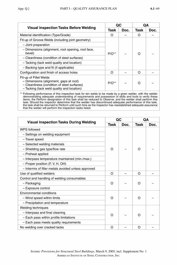
Seismic Provisions for Structural Steel Buildings, March 9, 2005, incl. Supplement No. 1AMERICAN INSTITUTE OF STEEL CONSTRUCTION, INC.
6.1–69
Visual Inspection Tasks Before WeldingQC QA
Task Doc. Task Doc.Material identification (Type/Grade) O – O –
Fit-up of Groove Welds (including joint geometry)
P/O** – O –
– Joint preparation – Dimensions (alignment, root opening, root face,
bevel) – Cleanliness (condition of steel surfaces)
– Tacking (tack weld quality and location)
– Backing type and fit (if applicable)
Configuration and finish of access holes O – O –
Fit-up of Fillet Welds – Dimensions (alignment, gaps at root) – Cleanliness (condition of steel surfaces) – Tacking (tack weld quality and location)
P/O** – O –
** Following performance of this inspection task for ten welds to be made by a given welder, with the welder demonstrating adequate understanding of requirements and possession of skills and tools to verify these items, the Perform designation of this task shall be reduced to Observe, and the welder shall perform this task. Should the inspector determine that the welder has discontinued adequate performance of this task, the task shall be returned to Perform until such time as the Inspector has reestablished adequate assurance that the welder will perform the inspection tasks listed.
Visual Inspection Tasks During WeldingQC QA
Task Doc. Task Doc.WPS followed
O – O –
– Settings on welding equipment
– Travel speed
– Selected welding materials
– Shielding gas type/flow rate
– Preheat applied
– Interpass temperature maintained (min./max.)
– Proper position (F, V, H, OH)
– Intermix of filler metals avoided unless approved
Use of qualified welders O – O –
Control and handling of welding consumables
O – O – – Packaging
– Exposure control
Environmental conditions
O – O – – Wind speed within limits
– Precipitation and temperature
Welding techniques
O – O – – Interpass and final cleaning
– Each pass within profile limitations
– Each pass meets quality requirements
No welding over cracked tacks O – O –
PART I – QUALITY ASSURANCE PLANApp. Q.]
SeismicProv1.indd 69SeismicProv1.indd 69 9/8/06 3:59:27 PM9/8/06 3:59:27 PMProcess BlackProcess Black
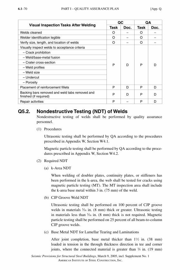
Seismic Provisions for Structural Steel Buildings, March 9, 2005, incl. Supplement No. 1AMERICAN INSTITUTE OF STEEL CONSTRUCTION, INC.
6.1–70
Visual Inspection Tasks After WeldingQC QA
Task Doc. Task Doc.Welds cleaned O – O –
Welder identification legible O – O –
Verify size, length, and location of welds O – O –
Visually inspect welds to acceptance criteria
P D P D
– Crack prohibition
– Weld/base-metal fusion
– Crater cross-section
– Weld profiles
– Weld size
– Undercut
– Porosity
Placement of reinforcement fillets P D P D
Backing bars removed and weld tabs removed and finished (if required) P D P D
Repair activities P – P D
Q5.2. Nondestructive Testing (NDT) of WeldsNondestructive testing of welds shall be performed by quality assurance personnel.
(1) Procedures
Ultrasonic testing shall be performed by QA according to the procedures prescribed in Appendix W, Section W4.1.
Magnetic particle testing shall be performed by QA according to the proce-dures prescribed in Appendix W, Section W4.2.
(2) Required NDT
(a) k-Area NDT
When welding of doubler plates, continuity plates, or stiffeners has been performed in the k-area, the web shall be tested for cracks using magnetic particle testing (MT). The MT inspection area shall include the k-area base metal within 3 in. (75 mm) of the weld.
(b) CJP Groove Weld NDT
Ultrasonic testing shall be performed on 100 percent of CJP groove welds in materials c in. (8 mm) thick or greater. Ultrasonic testing in materials less than c in. (8 mm) thick is not required. Magnetic particle testing shall be performed on 25 percent of all beam-to-column CJP groove welds.
(c) Base Metal NDT for Lamellar Tearing and Laminations
After joint completion, base metal thicker than 12 in. (38 mm) loaded in tension in the through thickness direction in tee and corner joints, where the connected material is greater than w in. (19 mm)
PART I – QUALITY ASSURANCE PLAN [App. Q.
SeismicProv1.indd 70SeismicProv1.indd 70 9/8/06 3:59:27 PM9/8/06 3:59:27 PMProcess BlackProcess Black
Seismic Provisions for Structural Steel Buildings, March 9, 2005, incl. Supplement No. 1AMERICAN INSTITUTE OF STEEL CONSTRUCTION, INC.
6.1–71
and contains CJP groove welds, shall be ultrasonically tested for discontinuities behind and adjacent to the fusion line of such welds. Any base metal discontinuities found within t/4 of the steel surface shall be accepted or rejected on the basis of criteria of AWS D1.1 Table 6.2, where t is the thickness of the part subjected to the through-thickness strain.
(d) Beam Cope and Access Hole NDT
At welded splices and connections, thermally cut surfaces of beam copes and access holes shall be tested using magnetic particle testing or penetrant testing, when the flange thickness exceeds 12 in. (38 mm) for rolled shapes, or when the web thickness exceeds 12 in. (38 mm) for built-up shapes.
(e) Reduced Beam Section Repair NDT
Magnetic particle testing shall be performed on any weld and adjacent area of the reduced beam section (RBS) plastic hinge region that has been repaired by welding, or on the base metal of the RBS plastic hinge region if a sharp notch has been removed by grinding.
(f) Weld Tab Removal Sites
Magnetic particle testing shall be performed on the end of welds from which the weld tabs have been removed, except for continuity plate weld tabs.
(g) Reduction of Percentage of Ultrasonic Testing
The amount of ultrasonic testing is permitted to be reduced if ap-proved by the engineer of record and the authority having jurisdic-tion. The nondestructive testing rate for an individual welder or welding operator may be reduced to 25 percent, provided the reject rate is demonstrated to be 5 percent or less of the welds tested for the welder or welding operator. A sampling of at least 40 completed welds for a job shall be made for such reduction evaluation. Reject rate is the number of welds containing rejectable defects divided by the number of welds completed. For evaluating the reject rate of continuous welds over 3 ft (1 m) in length where the effective throat thickness is 1 in. (25 mm) or less, each 12 in. (300 mm) increment or fraction thereof shall be considered as one weld. For evaluating the reject rate on continuous welds over 3 ft (1 m) in length where the effective throat thickness is greater than 1 in. (25 mm), each 6 in. (150 mm) of length or fraction thereof shall be considered one weld.
(h) Reduction of Percentage of Magnetic Particle Testing
The amount of MT on CJP groove welds is permitted to be reduced if approved by the engineer of record and the authority having jurisdic-tion. The MT rate for an individual welder or welding operator may be
PART I – QUALITY ASSURANCE PLANApp. Q.]
SeismicProv1.indd 71SeismicProv1.indd 71 9/8/06 3:59:27 PM9/8/06 3:59:27 PMProcess BlackProcess Black
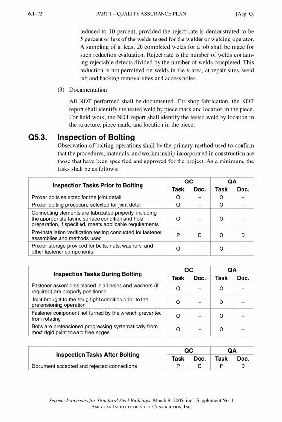
Seismic Provisions for Structural Steel Buildings, March 9, 2005, incl. Supplement No. 1AMERICAN INSTITUTE OF STEEL CONSTRUCTION, INC.
6.1–72
reduced to 10 percent, provided the reject rate is demonstrated to be 5 percent or less of the welds tested for the welder or welding operator. A sampling of at least 20 completed welds for a job shall be made for such reduction evaluation. Reject rate is the number of welds contain-ing rejectable defects divided by the number of welds completed. This reduction is not permitted on welds in the k-area, at repair sites, weld tab and backing removal sites and access holes.
(3) Documentation
All NDT performed shall be documented. For shop fabrication, the NDT report shall identify the tested weld by piece mark and location in the piece. For field work, the NDT report shall identify the tested weld by location in the structure, piece mark, and location in the piece.
Q5.3. Inspection of BoltingObservation of bolting operations shall be the primary method used to confirm that the procedures, materials, and workmanship incorporated in construction are those that have been specified and approved for the project. As a minimum, the tasks shall be as follows:
Inspection Tasks Prior to BoltingQC QA
Task Doc. Task Doc.Proper bolts selected for the joint detail O – O –
Proper bolting procedure selected for joint detail O – O –
Connecting elements are fabricated properly, including the appropriate faying surface condition and hole preparation, if specified, meets applicable requirements
O – O –
Pre-installation verification testing conducted for fastener assemblies and methods used P D O D
Proper storage provided for bolts, nuts, washers, and other fastener components O – O –
Inspection Tasks During BoltingQC QA
Task Doc. Task Doc.Fastener assemblies placed in all holes and washers (if required) are properly positioned O – O –
Joint brought to the snug tight condition prior to the pretensioning operation O – O –
Fastener component not turned by the wrench prevented from rotating O – O –
Bolts are pretensioned progressing systematically from most rigid point toward free edges O – O –
Inspection Tasks After BoltingQC QA
Task Doc. Task Doc.Document accepted and rejected connections P D P D
PART I – QUALITY ASSURANCE PLAN [App. Q.
SeismicProv1.indd 72SeismicProv1.indd 72 9/8/06 3:59:28 PM9/8/06 3:59:28 PMProcess BlackProcess Black
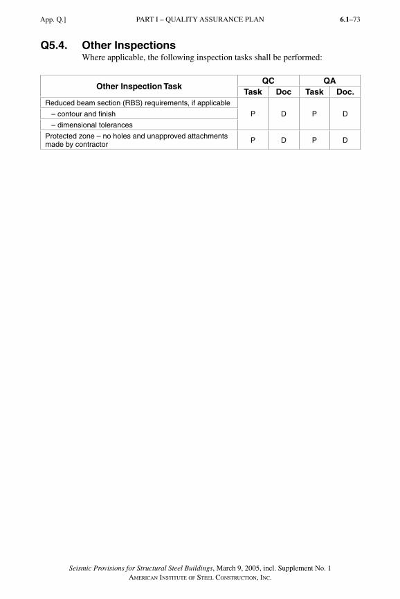
Seismic Provisions for Structural Steel Buildings, March 9, 2005, incl. Supplement No. 1AMERICAN INSTITUTE OF STEEL CONSTRUCTION, INC.
6.1–73
Q5.4. Other InspectionsWhere applicable, the following inspection tasks shall be performed:
Other Inspection TaskQC QA
Task Doc Task Doc.Reduced beam section (RBS) requirements, if applicable
P D P D – contour and finish
– dimensional tolerances
Protected zone – no holes and unapproved attachments made by contractor P D P D
PART I – QUALITY ASSURANCE PLANApp. Q.]
SeismicProv1.indd 73SeismicProv1.indd 73 9/8/06 3:59:28 PM9/8/06 3:59:28 PMProcess BlackProcess Black
Seismic Provisions for Structural Steel Buildings, March 9, 2005, incl. Supplement No. 1AMERICAN INSTITUTE OF STEEL CONSTRUCTION, INC.
6.1–74
APPENDIX R
SEISMIC DESIGN COEFFICIENTS AND
APPROXIMATE PERIOD PARAMETERS
R1. SCOPEThis appendix contains design coefficients, system limitations and design pa-rameters for seismic load resisting systems (SLRS) that are included in these Provisions but not yet defined in the applicable building code for buckling-re-strained braced frames (BRBF) and special plate shear walls (SPSW). The val-ues presented in Tables R3-1 and R4-1 in this appendix shall only be used where neither the applicable building code nor SEI/ASCE 7 contain such values.
User Note: The design coefficients and parameters presented in this appen-dix are taken from the 2003 NEHRP Recommended Provisions for Seismic Regulations for New Buildings and Other Structures. This appendix will be deleted from these Provisions once SEI/ASCE 7 and the applicable building codes add the BRBF and SPSW to their list of acceptable structural systems. It is expected that such parameters will be included in an appendix to SEI/ASCE 7 which is expected to be published in mid to late 2005.
R2. SYMBOLSThe following symbols are used in this appendix.
Cd Deflection amplification factor
Cr, x Parameters used for determining the approximate fundamental period
Ωo System overstrength factor
R Response modification coefficient
SeismicProv1.indd 74SeismicProv1.indd 74 9/8/06 3:59:28 PM9/8/06 3:59:28 PMProcess BlackProcess Black
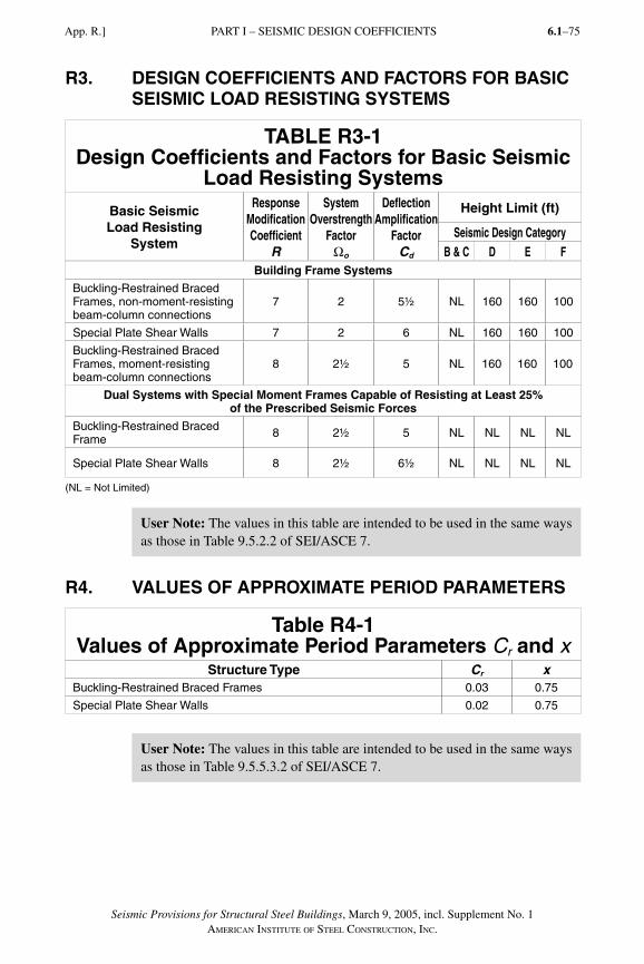
Seismic Provisions for Structural Steel Buildings, March 9, 2005, incl. Supplement No. 1AMERICAN INSTITUTE OF STEEL CONSTRUCTION, INC.
6.1–75
R3. DESIGN COEFFICIENTS AND FACTORS FOR BASIC SEISMIC LOAD RESISTING SYSTEMS
TABLE R3-1Design Coefficients and Factors for Basic Seismic
Load Resisting SystemsBasic SeismicLoad Resisting
System
Response Modification Coefficient
R
System Overstrength
FactorΩo
Deflection Amplification
FactorCd
Height Limit (ft)
Seismic Design CategoryB & C D E F
Building Frame Systems
Buckling-Restrained Braced Frames, non-moment-resisting beam-column connections
7 2 5½ NL 160 160 100
Special Plate Shear Walls 7 2 6 NL 160 160 100
Buckling-Restrained Braced Frames, moment-resisting beam-column connections
8 2½ 5 NL 160 160 100
Dual Systems with Special Moment Frames Capable of Resisting at Least 25% of the Prescribed Seismic Forces
Buckling-Restrained Braced Frame 8 2½ 5 NL NL NL NL
Special Plate Shear Walls 8 2½ 6½ NL NL NL NL
(NL = Not Limited)
User Note: The values in this table are intended to be used in the same ways as those in Table 9.5.2.2 of SEI/ASCE 7.
R4. VALUES OF APPROXIMATE PERIOD PARAMETERS
Table R4-1Values of Approximate Period Parameters Cr and x
Structure Type Cr xBuckling-Restrained Braced Frames 0.03 0.75
Special Plate Shear Walls 0.02 0.75
User Note: The values in this table are intended to be used in the same ways as those in Table 9.5.5.3.2 of SEI/ASCE 7.
PART I – SEISMIC DESIGN COEFFICIENTSApp. R.]
SeismicProv1.indd 75SeismicProv1.indd 75 9/8/06 3:59:28 PM9/8/06 3:59:28 PMProcess BlackProcess Black
Seismic Provisions for Structural Steel Buildings, March 9, 2005, incl. Supplement No. 1AMERICAN INSTITUTE OF STEEL CONSTRUCTION, INC.
6.1–76
APPENDIX S
QUALIFYING CYCLIC TESTS OF BEAM-TO-COLUMNAND LINK-TO-COLUMN CONNECTIONS
S1. SCOPEThis appendix includes requirements for qualifying cyclic tests of beam-to-column moment connections in special and intermediate moment frames and link-to-column connections in eccentrically braced frames, when required in these Provisions. The purpose of the testing described in this appendix is to pro-vide evidence that a beam-to-column connection or a link-to-column connection satisfies the requirements for strength and interstory drift angle or link rotation angle in these Provisions. Alternative testing requirements are permitted when approved by the engineer of record and the authority having jurisdiction.
This appendix provides minimum recommendations for simplified test conditions.
S2. SYMBOLSThe numbers in parentheses after the definition of a symbol refers to the Section number in which the symbol is first used.
θ Interstory drift angle (S6)
γtotal Total link rotation angle (S6)
S3. DEFINITIONSComplete loading cycle. A cycle of rotation taken from zero force to zero force,
including one positive and one negative peak.
Interstory drift angle. Interstory displacement divided by story height, radians.
Inelastic rotation. The permanent or plastic portion of the rotation angle between a beam and the column or between a link and the column of the test specimen, measured in radians. The inelastic rotation shall be computed based on an analysis of test specimen deformations. Sources of inelastic rotation include yielding of members, yielding of connection elements and connectors, and slip between members and connection elements. For beam-to-column mo-ment connections in special and intermediate moment frames, inelastic ro-tation is computed based upon the assumption that inelastic action is con-centrated at a single point located at the intersection of the centerline of the beam with the centerline of the column. For link-to-column connections in eccentrically braced frames, inelastic rotation shall be computed based upon the assumption that inelastic action is concentrated at a single point located at the intersection of the centerline of the link with the face of the column.
SeismicProv1.indd 76SeismicProv1.indd 76 9/8/06 3:59:28 PM9/8/06 3:59:28 PMProcess BlackProcess Black
Seismic Provisions for Structural Steel Buildings, March 9, 2005, incl. Supplement No. 1AMERICAN INSTITUTE OF STEEL CONSTRUCTION, INC.
6.1–77
Prototype. The connections, member sizes, steel properties, and other design, detailing, and construction features to be used in the actual building frame.
Test specimen. A portion of a frame used for laboratory testing, intended to mod-el the prototype.
Test setup. The supporting fixtures, loading equipment, and lateral bracing used to support and load the test specimen.
Test subassemblage. The combination of the test specimen and pertinent portions of the test setup.
Total link rotation angle. The relative displacement of one end of the link with respect to the other end (measured transverse to the longitudinal axis of the undeformed link), divided by the link length. The total link rotation angle shall include both elastic and inelastic components of deformation of the link and the members attached to the link ends.
S4. TEST SUBASSEMBLAGE REQUIREMENTSThe test subassemblage shall replicate as closely as is practical the conditions that will occur in the prototype during earthquake loading. The test subassem-blage shall include the following features:
(1) The test specimen shall consist of at least a single column with beams or links attached to one or both sides of the column.
(2) Points of inflection in the test assemblage shall coincide approximately with the anticipated points of inflection in the Prototype under earthquake loading.
(3) Lateral bracing of the test subassemblage is permitted near load appli-cation or reaction points as needed to provide lateral stability of the test subassemblage. Additional lateral bracing of the test subassemblage is not permitted, unless it replicates lateral bracing to be used in the prototype.
S5. ESSENTIAL TEST VARIABLESThe test specimen shall replicate as closely as is practical the pertinent design, detailing, construction features, and material properties of the prototype. The following variables shall be replicated in the test specimen.
S5.1. Sources of Inelastic RotationInelastic rotation shall be developed in the test specimen by inelastic action in the same members and connection elements as anticipated in the prototype (in other words, in the beam or link, in the column panel zone, in the column out-side of the panel zone, or in connection elements) within the limits described below. The percentage of the total inelastic rotation in the test specimen that is developed in each member or connection element shall be within 25 percent of the anticipated percentage of the total inelastic rotation in the proto-type that is developed in the corresponding member or connection element.
PART I – QUALIFYING CYCLIC TESTS OF CONNECTIONSApp. S.]
SeismicProv1.indd 77SeismicProv1.indd 77 9/8/06 3:59:29 PM9/8/06 3:59:29 PMProcess BlackProcess Black
Seismic Provisions for Structural Steel Buildings, March 9, 2005, incl. Supplement No. 1AMERICAN INSTITUTE OF STEEL CONSTRUCTION, INC.
6.1–78
S5.2. Size of MembersThe size of the beam or link used in the test specimen shall be within the follow-ing limits:
(1) The depth of the test beam or link shall be no less than 90 percent of the depth of the prototype beam or link.
(2) The weight per foot of the test beam or link shall be no less than 75 percent of the weight per foot of the prototype beam or link.
The size of the column used in the test specimen shall properly represent the inelastic action in the column, as per the requirements in Section S5.1. In addi-tion, the depth of the test column shall be no less than 90 percent of the depth of the prototype column.
Extrapolation beyond the limitations stated in this Section shall be permitted subject to qualified peer review and approval by the authority having jurisdiction.
S5.3. Connection DetailsThe connection details used in the test specimen shall represent the prototype connection details as closely as possible. The connection elements used in the test specimen shall be a full-scale representation of the connection elements used in the prototype, for the member sizes being tested.
S5.4. Continuity PlatesThe size and connection details of continuity plates used in the test specimen shall be proportioned to match the size and connection details of continuity plates used in the prototype connection as closely as possible.
S5.5. Material StrengthThe following additional requirements shall be satisfied for each member or con-nection element of the test specimen that supplies inelastic rotation by yielding:
(1) The yield stress shall be determined by material tests on the actual materials used for the test specimen, as specified in Section S8. The use of yield stress values that are reported on certified mill test reports are not permitted to be used for purposes of this Section.
(2) The yield stress of the beam shall not be more than 15 percent below Ry Fy for the grade of steel to be used for the corresponding elements of the proto-type. Columns and connection elements with a tested yield stress shall not be more than 15 percent above or below Ry Fy for the grade of steel to be used for the corresponding elements of the prototype. Ry Fy shall be deter-mined in accordance with Section 6.2.
PART I – QUALIFYING CYCLIC TESTS OF CONNECTIONS [App. S.
SeismicProv1.indd 78SeismicProv1.indd 78 9/8/06 3:59:29 PM9/8/06 3:59:29 PMProcess BlackProcess Black
Seismic Provisions for Structural Steel Buildings, March 9, 2005, incl. Supplement No. 1AMERICAN INSTITUTE OF STEEL CONSTRUCTION, INC.
6.1–79
S5.6. WeldsWelds on the test specimen shall satisfy the following requirements:
(1) Welding shall be performed in strict conformance with Welding Proce-dure Specifications (WPS) as required in AWS D1.1. The WPS essential variables shall meet the requirements in AWS D1.1 and shall be within the parameters established by the filler-metal manufacturer. The tensile strength of the welds used in the tested assembly and the Charpy V-Notch (CVN) toughness used in the tested assembly shall be determined by material tests as specified in Section S8.3. The use of tensile strength and CVN toughness values that are reported on the manufacturer’s typical certificate of conformance is not permitted to be used for purposes of this section, unless the report includes results specific to Appendix X requirements.
(2) The specified minimum tensile strength of the filler metal used for the test specimen shall be the same as that to be used for the corresponding proto-type welds. The tested tensile strength of the test specimen weld shall not be more than 25 ksi (125 MPa) above the tensile strength classification of the filler metal specification specified for the prototype.
(3) The specified minimum CVN toughness of the filler metal used for the test specimen shall not exceed the specified minimum CVN toughness of the filler metal to be used for the corresponding prototype welds. The tested CVN toughness of the test specimen weld shall not be more than 50 percent, nor 25 ft-lb (34 kJ), whichever is greater, above the minimum CVN tough-ness that will be specified for the prototype.
(4) The welding positions used to make the welds on the test specimen shall be the same as those to be used for the prototype welds.
(5) Details of weld backing, weld tabs, access holes, and similar items used for the test specimen welds shall be the same as those to be used for the corresponding prototype welds. Weld backing and weld tabs shall not be removed from the test specimen welds unless the corresponding weld back-ing and weld tabs are removed from the prototype welds.
(6) Methods of inspection and nondestructive testing and standards of accep-tance used for test specimen welds shall be the same as those to be used for the prototype welds.
S5.7. BoltsThe bolted portions of the test specimen shall replicate the bolted portions of the prototype connection as closely as possible. Additionally, bolted portions of the test specimen shall satisfy the following requirements:
(1) The bolt grade (for example, ASTM A325, A325M, ASTM A490, A490M, ASTM F1852) used in the test specimen shall be the same as that to be used for the prototype, except that ASTM A325 bolts may be substituted for ASTM F1852 bolts, and vice versa.
PART I – QUALIFYING CYCLIC TESTS OF CONNECTIONSApp. S.]
SeismicProv1.indd 79SeismicProv1.indd 79 9/8/06 3:59:29 PM9/8/06 3:59:29 PMProcess BlackProcess Black
Seismic Provisions for Structural Steel Buildings, March 9, 2005, incl. Supplement No. 1AMERICAN INSTITUTE OF STEEL CONSTRUCTION, INC.
6.1–80
(2) The type and orientation of bolt holes (standard, oversize, short slot, long slot, or other) used in the test specimen shall be the same as those to be used for the corresponding bolt holes in the prototype.
(3) When inelastic rotation is to be developed either by yielding or by slip within a bolted portion of the connection, the method used to make the bolt holes (drilling, sub-punching and reaming, or other) in the test specimen shall be the same as that to be used in the corresponding bolt holes in the prototype.
(4) Bolts in the test specimen shall have the same installation (pretensioned or other) and faying surface preparation (no specified slip resistance, Class A or B slip resistance, or other) as that to be used for the corresponding bolts in the prototype.
S6. LOADING HISTORY
S6.1. General RequirementsThe test specimen shall be subjected to cyclic loads according to the require-ments prescribed in Section S6.2 for beam-to-column moment connections in special and intermediate moment frames, and according to the requirements prescribed in Section S6.3 for link-to-column connections in eccentrically braced frames.
Loading sequences other than those specified in Sections S6.2 and S6.3 may be used when they are demonstrated to be of equivalent or greater severity.
S6.2. Loading Sequence for Beam-to-Column Moment ConnectionsQualifying cyclic tests of beam-to-column moment connections in special and intermediate moment frames shall be conducted by controlling the interstory drift angle, θ, imposed on the test specimen, as specified below:
(1) 6 cycles at θ = 0.00375 rad
(2) 6 cycles at θ = 0.005 rad
(3) 6 cycles at θ =0.0075 rad
(4) 4 cycles at θ = 0.01 rad
(5) 2 cycles at θ = 0.015 rad
(6) 2 cycles at θ = 0.02 rad
(7) 2 cycles at θ = 0.03 rad
(8) 2 cycles at θ = 0.04 rad
Continue loading at increments of θ = 0.01 radian, with two cycles of loading at each step.
PART I – QUALIFYING CYCLIC TESTS OF CONNECTIONS [App. S.
SeismicProv1.indd 80SeismicProv1.indd 80 9/8/06 3:59:29 PM9/8/06 3:59:29 PMProcess BlackProcess Black
Seismic Provisions for Structural Steel Buildings, March 9, 2005, incl. Supplement No. 1AMERICAN INSTITUTE OF STEEL CONSTRUCTION, INC.
6.1–81
S6.3. Loading Sequence for Link-to-Column ConnectionsQualifying cyclic tests of link-to-column moment connections in eccentrically braced frames shall be conducted by controlling the total link rotation angle, γtotal, imposed on the test specimen, as follows:
(1) 6 cycles at γtotal = 0.00375 rad
(2) 6 cycles at γtotal = 0.005 rad
(3) 6 cycles at γtotal = 0.0075 rad
(4) 6 cycles at γtotal = 0.01 rad
(5) 4 cycles at γtotal = 0.015 rad
(6) 4 cycles at γtotal = 0.02 rad
(7) 2 cycles at γtotal = 0.03 rad
(8) 1 cycle at γtotal = 0.04 rad
(9) 1 cycle at γtotal = 0.05 rad
(10) 1 cycle at γtotal = 0.07 rad
(11) 1 cycle at γtotal = 0.09 rad
Continue loading at increments of γtotal = 0.02 radian, with one cycle of loading at each step.
S7. INSTRUMENTATIONSufficient instrumentation shall be provided on the test specimen to permit measurement or calculation of the quantities listed in Section S9.
S8. MATERIALS TESTING REQUIREMENTS
S8.1. Tension Testing Requirements for Structural SteelTension testing shall be conducted on samples of steel taken from the mate-rial adjacent to each test specimen. Tension-test results from certified mill test reports shall be reported but are not permitted to be used in place of specimen testing for the purposes of this Section. Tension-test results shall be based upon testing that is conducted in accordance with Section S8.2. Tension testing shall be conducted and reported for the following portions of the test specimen:
(1) Flange(s) and web(s) of beams and columns at standard locations
(2) Any element of the connection that supplies inelastic rotation by yielding
S8.2. Methods of Tension Testing for Structural SteelTension testing shall be conducted in accordance with ASTM A6/A6M, ASTM A370, and ASTM E8, with the following exceptions:
(1) The yield stress, Fy, that is reported from the test shall be based upon the yield strength definition in ASTM A370, using the offset method at 0.002 strain.
PART I – QUALIFYING CYCLIC TESTS OF CONNECTIONSApp. S.]
SeismicProv1.indd 81SeismicProv1.indd 81 9/8/06 3:59:29 PM9/8/06 3:59:29 PMProcess BlackProcess Black
Seismic Provisions for Structural Steel Buildings, March 9, 2005, incl. Supplement No. 1AMERICAN INSTITUTE OF STEEL CONSTRUCTION, INC.
6.1–82
(2) The loading rate for the tension test shall replicate, as closely as practical, the loading rate to be used for the test specimen.
S8.3 Weld Metal Testing RequirementsThe tensile strength of the welds used in the tested assembly and the CVN tough-ness used in the tested assembly shall be determined by material tests as specified in Appendix X. The use of tensile strength and CVN toughness values that are re-ported on the manufacturer’s typical certificate of conformance is not permitted to be used for purposes of this section, unless that report includes results specific to Appendix X requirements.
A single test plate may be used if the WPS for the test specimen welds is within plus/minus 20 kJ/in. (0.8 kJ/mm) of the WPS for the test plate.
Tensile specimens and CVN specimens shall be prepared in accordance with ANSI/AWS B4.0 Standard Methods for Mechanical Testing of Welds.
S9. TEST REPORTING REQUIREMENTSFor each test specimen, a written test report meeting the requirements of the authority having jurisdiction and the requirements of this Section shall be pre-pared. The report shall thoroughly document all key features and results of the test. The report shall include the following information:
(1) A drawing or clear description of the test subassemblage, including key dimensions, boundary conditions at loading and reaction points, and location of lateral braces.
(2) A drawing of the connection detail showing member sizes, grades of steel, the sizes of all connection elements, welding details including filler metal, the size and location of bolt holes, the size and grade of bolts, and all other pertinent details of the connection.
(3) A listing of all other essential variables for the test specimen, as listed in Section S5.
(4) A listing or plot showing the applied load or displacement history of the test specimen.
(5) A listing of all demand critical welds.
(6) Definition of the region of the connection that comprises the protected zones.
(7) A plot of the applied load versus the displacement of the test specimen. The displacement reported in this plot shall be measured at or near the point of load application. The locations on the test specimen where the loads and displacements were measured shall be clearly indicated.
(8) A plot of beam moment versus interstory drift angle for beam-to-column moment connections; or a plot of link shear force versus link rotation angle for link-to-column connections. For beam-to-column connections, the beam moment and the interstory drift angle shall be computed with respect to the centerline of the column.
PART I – QUALIFYING CYCLIC TESTS OF CONNECTIONS [App. S.
SeismicProv1.indd 82SeismicProv1.indd 82 9/8/06 3:59:30 PM9/8/06 3:59:30 PMProcess BlackProcess Black
Seismic Provisions for Structural Steel Buildings, March 9, 2005, incl. Supplement No. 1AMERICAN INSTITUTE OF STEEL CONSTRUCTION, INC.
6.1–83
(9) The interstory drift angle and the total inelastic rotation developed by the test specimen. The components of the test specimen contributing to the total inelastic rotation due to yielding or slip shall be identified. The por-tion of the total inelastic rotation contributed by each component of the test specimen shall be reported. The method used to compute inelastic rotations shall be clearly shown.
(10) A chronological listing of significant test observations, including observa-tions of yielding, slip, instability, and fracture of any portion of the test specimen as applicable.
(11) The controlling failure mode for the test specimen. If the test is terminated prior to failure, the reason for terminating the test shall be clearly indicated.
(12) The results of the material tests specified in Section S8.
(13) The Welding Procedure Specifications (WPS) and welding inspection reports.
Additional drawings, data, and discussion of the test specimen or test results are permitted to be included in the report.
S10. ACCEPTANCE CRITERIAThe test specimen must satisfy the strength and interstory drift angle or link rotation angle requirements of these Provisions for the special moment frame, intermediate moment frame, or eccentrically braced frame connection, as appli-cable. The test specimen must sustain the required interstory drift angle or link rotation angle for at least one complete loading cycle.
PART I – QUALIFYING CYCLIC TESTS OF CONNECTIONSApp. S.]
SeismicProv1.indd 83SeismicProv1.indd 83 9/8/06 3:59:30 PM9/8/06 3:59:30 PMProcess BlackProcess Black
Seismic Provisions for Structural Steel Buildings, March 9, 2005, incl. Supplement No. 1AMERICAN INSTITUTE OF STEEL CONSTRUCTION, INC.
6.1–84
APPENDIX T
QUALIFYING CYCLIC TESTS OF BUCKLING-RESTRAINED BRACES
T1. SCOPE This appendix includes requirements for qualifying cyclic tests of individual buckling-restrained braces and buckling-restrained brace subassemblages, when required in these provisions. The purpose of the testing of individual braces is to provide evidence that a buckling-restrained brace satisfies the requirements for strength and inelastic deformation by these provisions; it also permits the determination of maximum brace forces for design of adjoining elements. The purpose of testing of the brace subassemblage is to provide evidence that the brace-design can satisfactorily accommodate the deformation and rotational de-mands associated with the design. Further, the subassemblage test is intended to demonstrate that the hysteretic behavior of the brace in the subassemblage is consistent with that of the individual brace elements tested uniaxially.
Alternative testing requirements are permitted when approved by the engineer of record and the authority having jurisdiction.
This appendix provides only minimum recommendations for simplified test conditions.
T2. SYMBOLSThe numbers in parentheses after the definition of a symbol refers to the Section number in which the symbol is first used.
Δb Deformation quantity used to control loading of the test specimen (total brace end rotation for the subassemblage test specimen; total brace axial deformation for the brace test specimen) (T6).
Δbm Value of deformation quantity, Δb, corresponding to the design story drift (T6).
Δby Value of deformation quantity, Δb, at first significant yield of test specimen (T6).
T3. DEFINITIONS
Brace test specimen. A single buckling-restrained brace element used for labora-tory testing intended to model the brace in the Prototype.
Design methodology. A set of step-by-step procedures, based on calculation or experiment, used to determine sizes, lengths, and details in the design of buckling-restrained braces and their connections.
SeismicProv1.indd 84SeismicProv1.indd 84 9/8/06 3:59:30 PM9/8/06 3:59:30 PMProcess BlackProcess Black
Seismic Provisions for Structural Steel Buildings, March 9, 2005, incl. Supplement No. 1AMERICAN INSTITUTE OF STEEL CONSTRUCTION, INC.
6.1–85
Inelastic deformation. The permanent or plastic portion of the axial displace-ment in a buckling-restrained brace.
Prototype. The brace, connections, members, steel properties, and other design, detailing, and construction features to be used in the actual building frame.
Subassemblage test specimen. The combination of the brace, the connections and testing apparatus that replicate as closely as practical the axial and flex-ural deformations of the brace in the prototype.
Test specimen. Brace test specimen or subassemblage test specimen.
T4. SUBASSEMBLAGE TEST SPECIMENThe subassemblage test specimen shall satisfy the following requirements:
(1) The mechanism for accommodating inelastic rotation in the subassemblage test specimen brace shall be the same as that of the prototype. The rotational deformation demands on the subassemblage test specimen brace shall be equal to or greater than those of the prototype.
(2) The axial yield strength of the steel core, Pysc, of the brace in the subassem-blage test specimen shall not be less than that of the prototype where both strengths are based on the core area, Asc, multiplied by the yield strength as determined from a coupon test.
(3) The cross-sectional shape and orientation of the steel core projection of the subassemblage test specimen brace shall be the same as that of the brace in the prototype.
(4) The same documented design methodology shall be used for design of the subassemblage as used for the prototype, to allow comparison of the rota-tional deformation demands on the subassemblage brace to the prototype. In stability calculations, beams, columns, and gussets connecting the core shall be considered parts of this system.
(5) The calculated margins of safety for the prototype connection design, steel core projection stability, overall buckling and other relevant subassemblage test specimen brace construction details, excluding the gusset plate, for the prototype, shall equal or exceed those of the subassemblage test specimen construction.
(6) Lateral bracing of the subassemblage test specimen shall replicate the lat-eral bracing in the prototype.
(7) The brace test specimen and the prototype shall be manufactured in accordance with the same quality control and assurance processes and procedures.
Extrapolation beyond the limitations stated in this section shall be permitted sub-ject to qualified peer review and approval by the authority having jurisdiction.
PART I – QUALIFYING CYCLIC TESTS OF BRBApp. T.]
SeismicProv1.indd 85SeismicProv1.indd 85 9/8/06 3:59:30 PM9/8/06 3:59:30 PMProcess BlackProcess Black
Seismic Provisions for Structural Steel Buildings, March 9, 2005, incl. Supplement No. 1AMERICAN INSTITUTE OF STEEL CONSTRUCTION, INC.
6.1–86
T5. BRACE TEST SPECIMEN The brace test specimen shall replicate as closely as is practical the pertinent de-sign, detailing, construction features, and material properties of the prototype.
T5.1. Design of Brace Test SpecimenThe same documented design methodology shall be used for the brace test speci-men and the prototype. The design calculations shall demonstrate, at a mini-mum, the following requirements:
(1) The calculated margin of safety for stability against overall buckling for the prototype shall equal or exceed that of the brace test specimen.
(2) The calculated margins of safety for the brace test specimen and the proto-type shall account for differences in material properties, including yield and ultimate stress, ultimate elongation, and toughness.
T5.2. Manufacture of Brace Test SpecimenThe brace test specimen and the prototype shall be manufactured in accordance with the same quality control and assurance processes and procedures.
T5.3. Similarity of Brace Test Specimen and PrototypeThe brace test specimen shall meet the following requirements:
(1) The cross-sectional shape and orientation of the steel core shall be the same as that of the prototype.
(2) The axial yield strength of the steel core, Pysc, of the brace test specimen shall not vary by more than 50 percent from that of the prototype where both strengths are based on the core area, Asc, multiplied by the yield strength as determined from a coupon test.
(3) The material for, and method of, separation between the steel core and the buckling restraining mechanism in the brace test specimen shall be the same as that in the prototype.
Extrapolation beyond the limitations stated in this section shall be permitted sub-ject to qualified peer review and approval by the authority having jurisdiction.
T5.4. Connection DetailsThe connection details used in the brace test specimen shall represent the proto-type connection details as closely as practical.
T5.5. Materials(1) Steel core: The following requirements shall be satisfied for the steel core
of the brace test specimen:
(a) The specified minimum yield stress of the brace test specimen steel core shall be the same as that of the prototype.
PART I – QUALIFYING CYCLIC TESTS OF BRB [App. T.
SeismicProv1.indd 86SeismicProv1.indd 86 9/8/06 3:59:30 PM9/8/06 3:59:30 PMProcess BlackProcess Black
Seismic Provisions for Structural Steel Buildings, March 9, 2005, incl. Supplement No. 1AMERICAN INSTITUTE OF STEEL CONSTRUCTION, INC.
6.1–87
(b) The measured yield stress of the material of the steel core in the brace test specimen shall be at least 90 percent of that of the prototype as determined from coupon tests.
(c) The specified minimum ultimate stress and strain of the brace test specimen steel core shall not exceed those of the prototype.
(2) Buckling-restraining mechanism
Materials used in the buckling-restraining mechanism of the brace test specimen shall be the same as those used in the prototype.
T5.6. ConnectionsThe welded, bolted, and pinned joints on the test specimen shall replicate those on the prototype as close as practical.
T6. LOADING HISTORYT6.1. General Requirements
The test specimen shall be subjected to cyclic loads according to the require-ments prescribed in Sections T6.2 and T6.3. Additional increments of loading beyond those described in Section T6.3 are permitted. Each cycle shall include a full tension and full compression excursion to the prescribed deformation.
T6.2. Test ControlThe test shall be conducted by controlling the level of axial or rotational defor-mation, Δb, imposed on the test specimen. As an alternate, the maximum rota-tional deformation may be applied and maintained as the protocol is followed for axial deformation.
T6.3. Loading SequenceLoads shall be applied to the test specimen to produce the following deforma-tions, where the deformation is the steel core axial deformation for the test speci-men and the rotational deformation demand for the subassemblage test specimen brace:
(1) 2 cycles of loading at the deformation corresponding to Δb = Δby
(2) 2 cycles of loading at the deformation corresponding to Δb = 0.50Δbm
(3) 2 cycles of loading at the deformation corresponding to Δb = 1Δbm
(4) 2 cycles of loading at the deformation corresponding to Δb = 1.5Δbm
(5) 2 cycles of loading at the deformation corresponding to Δb = 2.0Δbm.
(6) Additional complete cycles of loading at the deformation corresponding to Δb = 1.5Δbm as required for the brace test specimen to achieve a cumulative inelastic axial deformation of at least 200 times the yield deformation (not required for the subassemblage test specimen).
PART I – QUALIFYING CYCLIC TESTS OF BRBApp. T.]
SeismicProv1.indd 87SeismicProv1.indd 87 9/8/06 3:59:31 PM9/8/06 3:59:31 PMProcess BlackProcess Black
Seismic Provisions for Structural Steel Buildings, March 9, 2005, incl. Supplement No. 1AMERICAN INSTITUTE OF STEEL CONSTRUCTION, INC.
6.1–88
The design story drift shall not be taken as less than 0.01 times the story height for the purposes of calculating Δbm. Other loading sequences are permitted to be used to qualify the test specimen when they are demonstrated to be of equal or greater severity in terms of maximum and cumulative inelastic deformation.
T7. INSTRUMENTATIONSufficient instrumentation shall be provided on the test specimen to permit mea-surement or calculation of the quantities listed in Section T9.
T8. MATERIALS TESTING REQUIREMENTST8.1. Tension Testing Requirements
Tension testing shall be conducted on samples of steel taken from the same ma-terial as that used to manufacture the steel core. Tension test results from certi-fied mill test reports shall be reported but are not permitted to be used in place of specimen testing for the purposes of this Section. Tension-test results shall be based upon testing that is conducted in accordance with Section T8.2.
T8.2. Methods of Tension TestingTension testing shall be conducted in accordance with ASTM A6, ASTM A370, and ASTM E8, with the following exceptions:
(1) The yield stress that is reported from the test shall be based upon the yield strength definition in ASTM A370, using the offset method of 0.002 strain.
(2) The loading rate for the tension test shall replicate, as closely as is practical, the loading rate used for the test specimen.
(3) The coupon shall be machined so that its longitudinal axis is parallel to the longitudinal axis of the steel core.
T9. TEST REPORTING REQUIREMENTSFor each test specimen, a written test report meeting the requirements of this Section shall be prepared. The report shall thoroughly document all key features and results of the test. The report shall include the following information:
(1) A drawing or clear description of the test specimen, including key dimen-sions, boundary conditions at loading and reaction points, and location of lateral bracing, if any.
(2) A drawing of the connection details showing member sizes, grades of steel, the sizes of all connection elements, welding details including filler metal, the size and location of bolt or pin holes, the size and grade of connectors, and all other pertinent details of the connections.
(3) A listing of all other essential variables as listed in Section T4 or T5, as appropriate.
(4) A listing or plot showing the applied load or displacement history.
PART I – QUALIFYING CYCLIC TESTS OF BRB [App. T.
SeismicProv1.indd 88SeismicProv1.indd 88 9/8/06 3:59:31 PM9/8/06 3:59:31 PMProcess BlackProcess Black
Seismic Provisions for Structural Steel Buildings, March 9, 2005, incl. Supplement No. 1AMERICAN INSTITUTE OF STEEL CONSTRUCTION, INC.
6.1–89
(5) A plot of the applied load versus the deformation, Δb. The method used to determine the deformations shall be clearly shown. The locations on the test specimen where the loads and deformations were measured shall be clearly identified.
(6) A chronological listing of significant test observations, including observa-tions of yielding, slip, instability, transverse displacement along the test specimen and fracture of any portion of the test specimen and connections, as applicable.
(7) The results of the material tests specified in Section T8.
(8) The manufacturing quality control and quality assurance plans used for the fabrication of the test specimen. These shall be included with the welding procedure specifications and welding inspection reports.
Additional drawings, data, and discussion of the test specimen or test results are permitted to be included in the report.
T10. ACCEPTANCE CRITERIAAt least one subassemblage test that satisfies the requirements of Section T4 shall be performed. At least one brace test that satisfies the requirements of Sec-tion T5, shall be performed. Within the required protocol range all tests shall satisfy the following requirements:
(1) The plot showing the applied load vs. displacement history shall exhibit stable, repeatable behavior with positive incremental stiffness.
(2) There shall be no fracture, brace instability or brace end connection failure.
(3) For brace tests, each cycle to a deformation greater than Δby the maximum tension and compression forces shall not be less than the nominal strength of the core.
(4) For brace tests, each cycle to a deformation greater than Δby the ratio of the maximum compression force to the maximum tension force shall not exceed 1.3.
Other acceptance criteria may be adopted for the brace test specimen or subas-semblage test specimen subject to qualified peer review and approval by the authority having jurisdiction.
App. T.] PART I – QUALIFYING CYCLIC TESTS OF BRB
SeismicProv1.indd 89SeismicProv1.indd 89 9/8/06 3:59:31 PM9/8/06 3:59:31 PMProcess BlackProcess Black
Seismic Provisions for Structural Steel Buildings, March 9, 2005, incl. Supplement No. 1AMERICAN INSTITUTE OF STEEL CONSTRUCTION, INC.
6.1–90
APPENDIX W
WELDING PROVISIONS
W1. SCOPEThis appendix provides additional details regarding welding and welding inspec-tion, and is included on an interim basis pending adoption of such criteria by AWS or other accredited organization.
W2. STRUCTURAL DESIGN DRAWINGS AND SPECIFICATIONS, SHOP DRAWINGS, AND ERECTION DRAWINGS
W2.1. Structural Design Drawings and SpecificationsStructural design drawings and specifications shall include, as a minimum, the following information:
(1) Locations where backup bars are required to be removed
(2) Locations where supplemental fillet welds are required when backing is permitted to remain
(3) Locations where fillet welds are used to reinforce groove welds or to im-prove connection geometry
(4) Locations where weld tabs are required to be removed
(5) Splice locations where tapered transitions are required
User Note: Butt splices subject to tension greater than 33 percent of the ex-pected yield strength under any load combination should have tapered transi-tions. The stress concentration at a nontapered transition, based upon a 90° corner, could cause local yielding when the tensile stress exceeds 33 percent of yield. Lower levels of stress would be acceptable with the stress concentra-tion from a nontapered transition.
(6) The shape of weld access holes, if a special shape is required
(7) Joints or groups of joints in which a specific assembly order, welding sequence, welding technique or other special precautions are required
W2.2. Shop DrawingsShop drawings shall include, as a minimum, the following information:
(1) Access hole dimensions, surface profile and finish requirements
(2) Locations where backing bars are to be removed
SeismicProv1.indd 90SeismicProv1.indd 90 9/8/06 3:59:31 PM9/8/06 3:59:31 PMProcess BlackProcess Black
Seismic Provisions for Structural Steel Buildings, March 9, 2005, incl. Supplement No. 1AMERICAN INSTITUTE OF STEEL CONSTRUCTION, INC.
6.1–91
(3) Locations where weld tabs are to be removed
(4) NDT to be performed by the fabricator, if any
W2.3. Erection DrawingsErection drawings shall include, as a minimum, the following information:
(1) Locations where backing bars to be removed
(2) Locations where supplemental fillets are required when backing is permit-ted to remain
(3) Locations where weld tabs are to be removed
(4) Those joints or groups of joints in which a specific assembly order, welding sequence, welding technique or other special precautions are required
W3. PERSONNEL
W3.1. QC Welding InspectorsQC welding inspection personnel shall be associate welding inspectors (AWI) or higher, as defined in AWS B5.1 Standard for the Qualification of Welding In-spectors, or otherwise qualified under the provisions of AWS D1.1 Section 6.1.4 and to the satisfaction of the contractor’s QC plan by the fabricator/erector.
W3.2. QA Welding InspectorsQA welding inspectors shall be welding inspectors (WI), or senior welding in-spectors (SWI), as defined in AWS B5.1, except AWIs may be used under the direct supervision of WIs, on site and available when weld inspection is being conducted.
W3.3. Nondestructive Testing TechniciansNDT technicians shall be qualified as follows:
(1) In accordance with their employer’s written practice which shall meet or exceed the criteria of the American Society for Nondestructive Testing, Inc. SNT TC-1A Recommended Practice for the Training and Testing of Nonde-structive Personnel, or of ANSI/ASNT CP-189, Standard for the Qualifica-tion and Certification of Nondestructive Testing Personnel.
(2) Ultrasonic testing for QA may be performed only by UT technicians certi-fied as ASNT Level III through examination by the ASNT, or certified as Level II by their employer for flaw detection. If the engineer of record ap-proves the use of flaw sizing techniques, UT technicians shall also be quali-fied and certified by their employer for flaw sizing.
(3) Magnetic particle testing (MT) and dye penetrant testing (PT) for QA may be performed only by technicians certified as Level II by their employer, or certified as ASNT Level III through examination by the ASNT and certified by their employer.
PART I – WELDING PROVISIONSApp. W.]
SeismicProv1.indd 91SeismicProv1.indd 91 9/8/06 3:59:31 PM9/8/06 3:59:31 PMProcess BlackProcess Black
Seismic Provisions for Structural Steel Buildings, March 9, 2005, incl. Supplement No. 1AMERICAN INSTITUTE OF STEEL CONSTRUCTION, INC.
6.1–92
W4. NONDESTRUCTIVE TESTING PROCEDURES
W4.1. Ultrasonic TestingUltrasonic testing shall be performed according to the procedures prescribed in AWS D1.1 Section 6, Part F following a written procedure containing the ele-ments prescribed in paragraph K3 of Annex K. Section 6, Part F procedures shall be qualified using weld mock-ups having z-in. (1.5 mm)-diameter side drilled holes similar to Annex K, Figure K-3.
W4.2. Magnetic Particle TestingMagnetic particle testing shall be performed according to procedures prescribed in AWS D1.1, following a written procedure utilizing the Yoke Method that con-forms to ASTM E709.
W5. ADDITIONAL WELDING PROVISIONS
W5.1. Intermixed Filler MetalsWhen FCAW-S filler metals are used in combination with filler metals of other processes, including FCAW-G, a test specimen shall be prepared and mechani-cal testing shall be conducted to verify that the notch toughness of the combined materials in the intermixed region of the weld meets the notch toughness require-ments of Section 7.3a and, if required, the notch toughness requirements for demand critical welds of Section 7.3b.
W5.2. Filler Metal Diffusible HydrogenWelding electrodes and electrode-flux combinations shall meet the require-ments for H16 (16 mL maximum diffusible hydrogen per 100 grams depos-ited weld metal) as tested in accordance with AWS A4.3 Standard Methods for Determination of the Diffusible Hydrogen Content of Martensitic, Bainitic, and Ferritic Steel Weld Metal Produced by Arc Welding. (Exception: GMAW solid electrodes.) The manufacturer’s typical certificate of conformance shall be con-sidered adequate proof that the supplied electrode or electrode-flux combination meets this requirement. No testing of filler metal samples or of production welds shall be required.
W5.3. Gas-Shielded Welding ProcessesGMAW and FCAW-G shall not be performed in winds exceeding 3 mph (5 km/hr). Windscreens or other shelters may be used to shield the welding operation from excessive wind.
W5.4. Maximum Interpass TemperaturesMaximum interpass temperatures shall not exceed 550 oF (290 oC), measured at a distance not exceeding 3 in. (75 mm) from the start of the weld pass. The maximum interpass temperature may be increased by qualification testing that includes weld metal and base metal CVN testing using AWS D1.1 Annex III. The steel used for the qualification testing shall be of the same type and grade as will be used in production.
PART I – WELDING PROVISIONS [App. W.
SeismicProv1.indd 92SeismicProv1.indd 92 9/8/06 3:59:32 PM9/8/06 3:59:32 PMProcess BlackProcess Black
Seismic Provisions for Structural Steel Buildings, March 9, 2005, incl. Supplement No. 1AMERICAN INSTITUTE OF STEEL CONSTRUCTION, INC.
6.1–93
The maximum heat input to be used in production shall be used in the qualifica-tion testing. The qualified maximum interpass temperature shall be the lowest interpass temperature used for any pass during qualification testing. Both weld metal and HAZ shall be tested. The weld metal shall meet all the mechanical properties required by Section 7.3a, or those for demand critical welds of Sec-tion 7.3b, as applicable. The heat affected zone CVN toughness shall meet a minimum requirement of 20 ft-lbf (27 J) at 70 °F (21 °C) with specimens taken at both 1 and 5 mm from the fusion line.
W5.5. Weld TabsWhere practicable, weld tabs shall extend beyond the edge of the joint a mini-mum of one inch or the thickness of the part, whichever is greater. Extensions need not exceed 2 in. (50 mm).
Where used, weld tabs shall be removed to within 8 in. (3 mm) of the base metal surface, except at continuity plates where removal to within 4 in. (6 mm) of the plate edge is acceptable, and the end of the weld finished. Removal shall be by air carbon arc cutting (CAC-A), grinding, chipping, or thermal cutting. The process shall be controlled to minimize errant gouging. The edges where weld tabs have been removed shall be finished to a surface roughness of 500 μin. (13 μm) or better. Grinding to a flush condition is not required. The contour of the weld end shall provide a smooth transition, free of notches and sharp corners. At T-joints, a minimum radius in the corner need not be provided. The weld end shall be free of gouges and notches. Weld defects not greater than z in. (2 mm) deep shall be faired to a slope not greater than 1:5. Other weld defects shall be excavated and repaired by welding in accordance with an applicable WPS.
W5.6. Bottom Flange Welding SequenceWhen using weld access holes to facilitate CJP groove welds of beam bottom flanges to column flanges or continuity plates, the groove weld shall be se-quenced as follows:
(1) As far as is practicable, starts and stops shall not be placed directly under the beam web.
(2) Each layer shall be completed across the full width of the flange before beginning the next layer.
(3) For each layer, the weld starts and stops shall be on the opposite side of the beam web, as compared to the previous layer.
W6. ADDITIONAL WELDING PROVISIONS FOR DEMAND CRITICAL WELDS ONLY
W6.1. Welding ProcessesSMAW, GMAW (except short circuit transfer), FCAW and SAW may be used to fabricate and erect members governed by this specification. Other processes may be used, provided that one or more of the following criteria is met:
PART I – WELDING PROVISIONSApp. W.]
SeismicProv1.indd 93SeismicProv1.indd 93 9/8/06 3:59:32 PM9/8/06 3:59:32 PMProcess BlackProcess Black
Seismic Provisions for Structural Steel Buildings, March 9, 2005, incl. Supplement No. 1AMERICAN INSTITUTE OF STEEL CONSTRUCTION, INC.
6.1–94
(a) The process is part of the prequalified connection details, as listed in Appendix P,
(b) The process was used to perform a connection qualification test in accordance with Appendix S, or
(c) The process is approved by the engineer of record.
W6.2. Filler Metal PackagingElectrodes shall be provided in packaging that limits the ability of the electrode to absorb moisture. Electrode from packaging that has been punctured or torn shall be dried in accordance with the manufacturer’s recommendations, or shall not be used for demand critical welds. Modification or lubrication of the elec-trode after manufacture is prohibited, except that drying is permitted as recom-mended by the manufacturer.
W6.3. Exposure Limitations on FCAW ElectrodesAfter removal from protective packaging, the permissible atmospheric exposure time of FCAW electrodes shall be limited as follows:
(1) Exposure shall not exceed the electrode manufacturer’s guidelines.
(2) In the absence of manufacturer’s recommendations, the total accumulated exposure time for FCAW electrodes shall not exceed 72 hours. When the electrodes are not in use, they may be stored in protective packaging or a cabinet. Storage time shall not be included in the accumulated exposure time. Electrodes that have been exposed to the atmosphere for periods ex-ceeding the above time limits shall be dried in accordance with the electrode manufacturer’s recommendations, or shall not be used for demand critical welds. The electrode manufacturer’s recommendations shall include time, temperature, and number of drying cycles permitted.
W6.4. Tack WeldsTack welds attaching backing bars and weld tabs shall be placed where they will be incorporated into a final weld.
PART I – WELDING PROVISIONS [App. W.
SeismicProv1.indd 94SeismicProv1.indd 94 9/8/06 3:59:32 PM9/8/06 3:59:32 PMProcess BlackProcess Black
Seismic Provisions for Structural Steel Buildings, March 9, 2005, incl. Supplement No. 1AMERICAN INSTITUTE OF STEEL CONSTRUCTION, INC.
6.1–95
APPENDIX X
WELD METAL/WELDING PROCEDURE SPECIFICATION NOTCH TOUGHNESS
VERIFICATION TEST
This appendix provides a procedure for qualifying the weld metal toughness and is included on an interim basis pending adoption of such a procedure by the American Welding Society (AWS) or other accredited organization.
X1. SCOPEThis appendix provides a standard method for qualification testing of weld filler metals required to have specified notch toughness for service in joints designated as demand critical.
Testing of weld metal to be used in production shall be performed by filler metal manufacturer’s production lot, as defined in AWS A5.01, Filler Metal Procure-ment Guidelines, as follows:
(1) Class C3 for SMAW electrodes,
(2) Class S2 for GMAW-S and SAW electrodes,
(3) Class T4 for FCAW and GMAW-C, or
(4) Class F2 for SAW fluxes.
Filler metals produced by manufacturers audited and approved by one or more of the following agencies shall be exempt from these production lot testing require-ments, provided a minimum of 3 production lots of material, as defined above, are tested in accordance with the provisions of this appendix:
(1) American Bureau of Shipping (ABS),
(2) Lloyds Register of Shipping,
(3) American Society of Mechanical Engineers (ASME),
(4) ISO 9000,
(5) US Department of Defense, or
(6) A quality assurance program acceptable to the engineer of record.
Under this exemption from production lot testing, the filler metal manufacturer shall repeat the testing prescribed in this appendix at least every three years on a random production lot.
SeismicProv1.indd 95SeismicProv1.indd 95 9/8/06 3:59:32 PM9/8/06 3:59:32 PMProcess BlackProcess Black
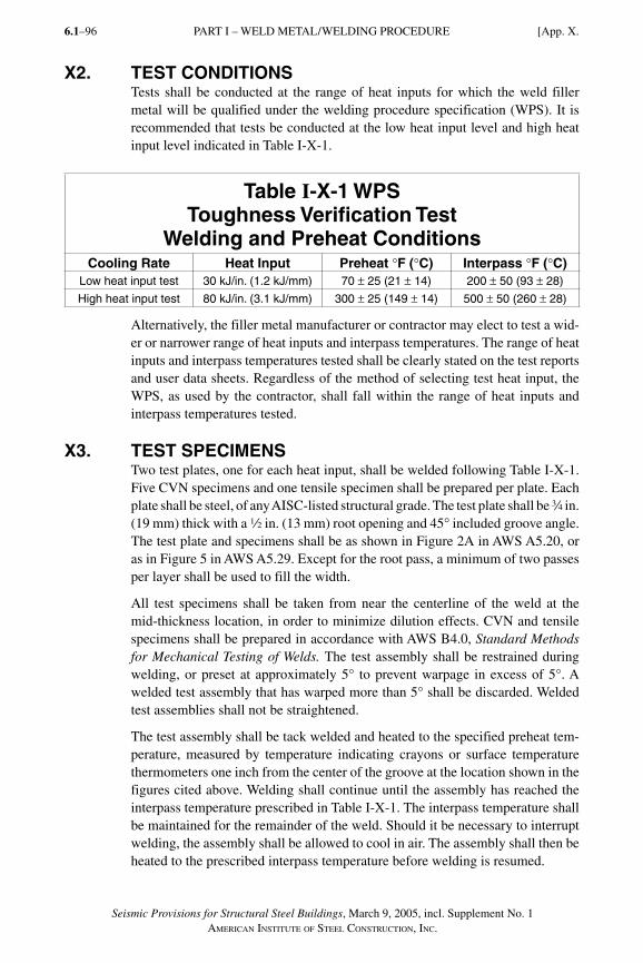
X2. TEST CONDITIONSTests shall be conducted at the range of heat inputs for which the weld filler metal will be qualified under the welding procedure specification (WPS). It is recommended that tests be conducted at the low heat input level and high heat input level indicated in Table I-X-1.
Table I-X-1 WPS Toughness Verification Test
Welding and Preheat ConditionsCooling Rate Heat Input Preheat °F (°C) Interpass °F (°C)
Low heat input test 30 kJ/in. (1.2 kJ/mm) 70 ± 25 (21 ± 14) 200 ± 50 (93 ± 28)
High heat input test 80 kJ/in. (3.1 kJ/mm) 300 ± 25 (149 ± 14) 500 ± 50 (260 ± 28)
Alternatively, the filler metal manufacturer or contractor may elect to test a wid-er or narrower range of heat inputs and interpass temperatures. The range of heat inputs and interpass temperatures tested shall be clearly stated on the test reports and user data sheets. Regardless of the method of selecting test heat input, the WPS, as used by the contractor, shall fall within the range of heat inputs and interpass temperatures tested.
X3. TEST SPECIMENSTwo test plates, one for each heat input, shall be welded following Table I-X-1. Five CVN specimens and one tensile specimen shall be prepared per plate. Each plate shall be steel, of any AISC-listed structural grade. The test plate shall be w in. (19 mm) thick with a 2 in. (13 mm) root opening and 45° included groove angle. The test plate and specimens shall be as shown in Figure 2A in AWS A5.20, or as in Figure 5 in AWS A5.29. Except for the root pass, a minimum of two passes per layer shall be used to fill the width.
All test specimens shall be taken from near the centerline of the weld at the mid-thickness location, in order to minimize dilution effects. CVN and tensile specimens shall be prepared in accordance with AWS B4.0, Standard Methods for Mechanical Testing of Welds. The test assembly shall be restrained during welding, or preset at approximately 5° to prevent warpage in excess of 5°. A welded test assembly that has warped more than 5° shall be discarded. Welded test assemblies shall not be straightened.
The test assembly shall be tack welded and heated to the specified preheat tem-perature, measured by temperature indicating crayons or surface temperature thermometers one inch from the center of the groove at the location shown in the figures cited above. Welding shall continue until the assembly has reached the interpass temperature prescribed in Table I-X-1. The interpass temperature shall be maintained for the remainder of the weld. Should it be necessary to interrupt welding, the assembly shall be allowed to cool in air. The assembly shall then be heated to the prescribed interpass temperature before welding is resumed.
[App. X.PART I – WELD METAL/WELDING PROCEDURE6.1–96
Seismic Provisions for Structural Steel Buildings, March 9, 2005, incl. Supplement No. 1AMERICAN INSTITUTE OF STEEL CONSTRUCTION, INC.
SeismicProv1.indd 96SeismicProv1.indd 96 9/8/06 3:59:32 PM9/8/06 3:59:32 PMProcess BlackProcess Black
Seismic Provisions for Structural Steel Buildings, March 9, 2005, incl. Supplement No. 1AMERICAN INSTITUTE OF STEEL CONSTRUCTION, INC.
6.1–97
No thermal treatment of weldment or test specimens is permitted, except that machined tensile test specimens may be aged at 200 °F (93 °C) to 220 °F (104 °C) for up to 48 hours, then cooled to room temperature before testing.
X4. ACCEPTANCE CRITERIAThe lowest and highest Charpy V-Notch (CVN) toughness values obtained from the five specimens from a single test plate shall be disregarded. Two of the re-maining three values shall equal, or exceed, the specified toughness of 40 ft-lbf (54 J) energy level at the testing temperature. One of the three may be lower, but not lower than 30 ft-lbf (41 J), and the average of the three shall not be less than the required 40 ft-lbf (54 J) energy level. All test samples shall meet the notch toughness requirements for the electrodes as provided in Section 7.3b.
For filler metals classified as E70, materials shall provide a minimum yield stress of 58 ksi, a minimum tensile strength of 70 ksi, and a minimum elongation of 22 percent. For filler metals classified as E80, materials shall provide a minimum yield stress of 68 ksi, a minimum tensile strength of 80 ksi, and a minimum elongation of 19 percent.
PART I – WELD METAL/WELDING PROCEDUREApp. X.]
SeismicProv1.indd 97SeismicProv1.indd 97 9/8/06 3:59:33 PM9/8/06 3:59:33 PMProcess BlackProcess Black

6.1–98
Seismic Provisions for Structural Steel Buildings, March 9, 2005, incl. Supplement No. 1AMERICAN INSTITUTE OF STEEL CONSTRUCTION, INC.
SeismicProv1.indd 98SeismicProv1.indd 98 9/8/06 3:59:33 PM9/8/06 3:59:33 PMProcess BlackProcess Black
Seismic Provisions for Structural Steel Buildings, March 9, 2005, incl. Supplement No. 1AMERICAN INSTITUTE OF STEEL CONSTRUCTION, INC.
6.1–99
PART II. COMPOSITE STRUCTURAL STEEL AND REINFORCED CONCRETE BUILDINGS
GLOSSARY
These terms are in addition to those listed in Part I. Glossary terms are generally italicized where they first appear within a section throughout this Part and in the Commentary.
Boundary member. Portion along wall and diaphragm edge strengthened with structural steel sections and/or longitudinal steel reinforcement and transverse reinforcement.
Collector element. Member that serves to transfer loads between floor diaphragms and the members of the seismic load resisting system.
Composite beam. Structural steel beam in contact with and acting compositely with reinforced concrete via bond or shear connectors.
Composite brace. Reinforced-concrete-encased structural steel section (rolled or built-up) or concrete-filled steel section used as a brace.
Composite column. Reinforced-concrete-encased structural steel section (rolled or built-up) or concrete-filled steel section used as a column.
Composite eccentrically braced frame (C-EBF). Composite braced frame meeting the requirements of Section 14.
Composite intermediate moment frame (C-IMF). Composite moment frame meeting the requirements of Section 10.
Composite ordinary braced frame (C-OBF). Composite braced frame meeting the requirements of Section 13.
Composite ordinary moment frame (C-OMF). Composite moment frame meeting the requirements of Section 11.
Composite partially restrained moment frame (C-PRMF). Composite moment frame meeting the requirements of Section 8.
Composite shear wall. Reinforced concrete wall that has unencased or reinforced-concrete-encased structural steel sections as boundary members.
Composite slab. Concrete slab supported on and bonded to a formed steel deck that acts as a diaphragm to transfer load to and between elements of the seismic load resisting system.
Composite special concentrically braced frame (C-CBF). Composite braced frame meeting the requirements of Section 12.
Composite special moment frame (C-SMF). Composite moment frame meeting the requirements of Section 9.
SeismicProv2.indd 99SeismicProv2.indd 99 9/8/06 11:45:05 AM9/8/06 11:45:05 AMProcess BlackProcess Black
6.1–100
Seismic Provisions for Structural Steel Buildings, March 9, 2005, incl. Supplement No. 1AMERICAN INSTITUTE OF STEEL CONSTRUCTION, INC.
Composite steel plate shear wall (C-SPW). Wall consisting of steel plate with reinforced concrete encasement on one or both sides that provides out-of-plane stiffening to prevent buckling of the steel plate and meeting the requirements of Section 17.
Coupling beam. Structural steel or composite beam connecting adjacent reinforced concrete wall elements so that they act together to resist lateral loads.
Encased composite beam. Composite beam completely enclosed in reinforced concrete.
Encased composite column. Structural steel column (rolled or built-up) completely encased in reinforced concrete.
Face bearing plates. Stiffeners attached to structural steel beams that are embedded in reinforced concrete walls or columns. The plates are located at the face of the reinforced concrete to provide confinement and to transfer loads to the concrete through direct bearing.
Filled composite column. Round or rectangular structural steel section filled with concrete.
Fully composite beam. Composite beam that has a sufficient number of shear connectors to develop the nominal plastic flexural strength of the composite section.
Intermediate seismic systems. Seismic systems designed assuming moderate inelastic action occurs in some members under the design earthquake.
Load-carrying reinforcement. Reinforcement in composite members designed and detailed to resist the required loads.
Ordinary reinforced concrete shear wall with structural steel elements (C-ORCW). Composite shear walls meeting the requirements of Section 15.
Ordinary seismic systems. Seismic systems designed assuming limited inelastic action occurs in some members under the design earthquake.
Partially composite beam. Unencased composite beam with a nominal flexural strength controlled by the strength of the shear stud connectors.
Partially restrained composite connection. Partially restrained (PR) connections as defined in the Specification that connect partially or fully composite beams to steel columns with flexural resistance provided by a force couple achieved with steel reinforcement in the slab and a steel seat angle or similar connection at the bottom flange.
Reinforced-concrete-encased shapes. Structural steel sections encased in reinforced concrete.
Restraining bars. Steel reinforcement in composite members that is not designed to carry required loads, but is provided to facilitate the erection of other steel reinforcement and to provide anchorage for stirrups or ties. Generally, such reinforcement is not spliced to be continuous.
Special reinforced concrete shear walls composite with structural steel elements (C-SRCW).Composite shear walls meeting the requirements of Section 16.
Special seismic systems. Seismic systems designed assuming significant inelastic action occurs in some members under the design earthquake.
Unencased composite beam. Composite beam wherein the steel section is not completely enclosed in reinforced concrete and relies on mechanical connectors for composite action with a reinforced slab or slab on metal deck.
PART II – GLOSSARY
SeismicProv2.indd 100SeismicProv2.indd 100 9/8/06 11:45:05 AM9/8/06 11:45:05 AMProcess BlackProcess Black
Seismic Provisions for Structural Steel Buildings, March 9, 2005, incl. Supplement No. 1AMERICAN INSTITUTE OF STEEL CONSTRUCTION, INC.
Sect. 2.] 6.1–101
1. SCOPEThese Provisions shall govern the design, fabrication, and erection of composite structural steel and reinforced concrete members and connections in the seismic load resisting systems (SLRS) in buildings and other structures, where other structures are defined as those designed, fabricated, and erected in a manner simi-lar to buildings, with building-like vertical and lateral load-resisting systems. These provisions shall apply when the seismic response modification coefficient, R, (as specified in the applicable building code) is taken greater than 3. When the seismic response modification coefficient, R, is taken as 3 or less, the struc-ture is not required to satisfy these provisions unless required by the applicable building code.
The requirements of Part II modify and supplement the requirements of Part I and form these Provisions. They shall be applied in conjunc tion with the AISC Specification for Structural Steel Buildings, ANSI/AISC 360, hereinafter re-ferred to as the Specificat ion. The applicable requirements of the Building Code Requirements for Structural Concrete and Commentary, ACI 318, as modified in these Provisions shall be used for the design of reinforced concrete components in composite SLRS.
For seismic load resisting systems incorporating reinforced concrete components designed according to ACI 318, the requirements for load and resistance factor design as specified in Section B3.3 of the Specification shall be used.
When the design is based upon elastic analysis, the stiffness properties of the component members of composite systems shall reflect their condition at the onset of significant yielding of the structure.
Wherever these Provisions refer to the applicable building code (ABC) and there is no local building code, the loads, load combinations, system limitations and general design requirements shall be those in SEI/ASCE 7.
Part II includes a Glossary which is specifically applicable to this Part. The Part I Glossary is also applicable to Part II.
2. REFERENCED SPECIFICATIONS, CODES, AND STANDARDSThe documents referenced in these provisions shall include those listed in Part I Section 2 with the following additions:
American Society of Civil EngineersStandard for the Structural Design of Composite Slabs, ASCE 3-91
American Welding SocietyStructural Welding Code-Reinforcing Steel, AWS D1.4-98
PART II – REFERENCED SPECIFICATIONS, CODES, AND STANDARDS
SeismicProv2.indd 101SeismicProv2.indd 101 9/8/06 11:45:05 AM9/8/06 11:45:05 AMProcess BlackProcess Black
6.1–102
Seismic Provisions for Structural Steel Buildings, March 9, 2005, incl. Supplement No. 1AMERICAN INSTITUTE OF STEEL CONSTRUCTION, INC.
3. GENERAL SEISMIC DESIGN REQUIREMENTS The required strength and other provisions for seismic design categories (SDCs) and seismic use groups and the limitations on height and irregularity shall be as specified in the applicable building code.
The design story drift and story drift limits shall be determined as required in the applicable building code.
4. LOADS, LOAD COMBINATIONS, AND NOMINAL STRENGTHS
4.1. Loads and Load CombinationsWhere amplified seismic loads are required by these Provisions, the horizontal portion of the earthquake load E (as defined in the applicable building code) shall be multiplied by the overstrength factor Ωo prescribed by the applicable building code.
For the seismic load resisting system (SLRS) incorporating reinforced concrete components designed according to ACI 318, the requirements of Section B3.3 of the Specification shall be used.
User Note: When not defined in the applicable building code, Ωo should be taken from SEI/ASCE 7.
4.2. Nominal StrengthThe nominal strength of systems, members, and connections shall be determined in accordance with the requirements of the Specification, except as modified throughout these Provisions.
5. MATERIALS
5.1. Structural SteelStructural steel members and connections used in composite seismic load resist-ing systems (SLRS) shall meet the requirements of Specification Section A3. Structural steel used in the composite SLRS described in Sections 8, 9, 12, 14, 16 and 17 shall also meet the requirements in Part I Sections 6 and 7.
5.2. Concrete and Steel ReinforcementConcrete and steel reinforcement used in composite components in composite SLRS shall meet the requirements of ACI 318, Sections 21.2.4 through 21.2.8.
Exception: Concrete and steel reinforcement used in the composite ordinary seismic systems described in Sections 11, 13, and 15 shall meet the requirements of Specification Chapter I and ACI 318, excluding Chapter 21.
PART II – GENERAL SEISMIC DESIGN REQUIREMENTS [Sect. 3.
SeismicProv2.indd 102SeismicProv2.indd 102 9/8/06 11:45:05 AM9/8/06 11:45:05 AMProcess BlackProcess Black
Seismic Provisions for Structural Steel Buildings, March 9, 2005, incl. Supplement No. 1AMERICAN INSTITUTE OF STEEL CONSTRUCTION, INC.
6.1–103
6. COMPOSITE MEMBERS
6.1. ScopeThe design of composite members in the SLRS described in Sections 8 through 17 shall meet the requirements of this Section and the material requirements of Section 5.
6.2. Composite Floor and Roof SlabsThe design of composite floor and roof slabs shall meet the requirements of ASCE 3. Composite slab diaphragms shall meet the requirements in this Section.
6.2a. Load TransferDetails shall be designed so as to transfer loads between the diaphragm and boundary members, collector elements, and elements of the horizontal framing system.
6.2b. Nominal Shear StrengthThe nominal shear strength of composite diaphragms and concrete-filled steel deck diaphragms shall be taken as the nominal shear strength of the reinforced concrete above the top of the steel deck ribs in accordance with ACI 318 exclud-ing Chapter 22. Alternatively, the composite diaphragm nominal shear strength shall be determined by in-plane shear tests of concrete-filled diaphragms.
6.3. Composite BeamsComposite beams shall meet the requirements of Specification Chapter I. Com-posite beams that are part of composite-special moment frames (C-SMF) shall also meet the requirements of Section 9.3.
6.4. Encased Composite ColumnsThis section is applicable to columns that (1) consist of reinforced-concrete-encased shapes with a structural steel area that comprises at least 1 percent of the total composite column cross section; and (2) meet the additional limitations of Specification Section I2.1. Such columns shall meet the requirements of Specifi-cation Chapter I, except as modified in this Section. Additional requirements, as specified for intermediate and special seismic systems in Sections 6.4b and 6.4c shall apply as required in the descriptions of the composite seismic systems in Sections 8 through 17.
Columns that consist of reinforced-concrete-encased shapes shall meet the re-quirements for reinforced concrete columns of ACI 318 except as modified for
(1) The structural steel section shear connectors in Section 6.4a(2).
(2) The contribution of the reinforced-concrete-encased shape to the strength of the column as provided in ACI 318.
(3) The seismic requirements for reinforced concrete columns as specified in the description of the composite seismic systems in Sections 8 through 17.
PART II – COMPOSITE MEMBERSSect. 6.]
SeismicProv2.indd 103SeismicProv2.indd 103 9/8/06 11:45:06 AM9/8/06 11:45:06 AMProcess BlackProcess Black
6.1–104
Seismic Provisions for Structural Steel Buildings, March 9, 2005, incl. Supplement No. 1AMERICAN INSTITUTE OF STEEL CONSTRUCTION, INC.
6.4a. Ordinary Seismic System RequirementsThe following requirements for encased composite columns are applicable to all composite systems, including ordinary seismic systems:
(1) The available shear strength of the column shall be determined in accor-dance with Specification Section I2.1d. The nominal shear strength of the tie reinforcement shall be determined in accordance with ACI 318 Sections 11.5.6.2 through 11.5.6.9. In ACI 318 Sections 11.5.6.5 and 11.5.6.9, the dimension bw shall equal the width of the concrete cross-section minus the width of the structural shape measured perpendicular to the direction of shear.
(2) Composite columns designed to share the applied loads between the struc-tural steel section and the reinforced concrete encasement shall have shear connectors that meet the requirements of Specification Section I2.1.
(3) The maximum spacing of transverse ties shall meet the requirements of Specification Section I2.1.
Transverse ties shall be located vertically within one-half of the tie spacing above the top of the footing or lowest beam or slab in any story and shall be spaced as provided herein within one-half of the tie spacing below the lowest beam or slab framing into the column.
Transverse bars shall have a diameter that is not less than one-fifti-eth of the greatest side dimension of the composite member, except that ties shall not be smaller than No. 3 bars and need not be larger than No. 5 bars. Alternatively, welded wire fabric of equivalent area is permitted as transverse reinforcement except when prohibited for intermediate and special seismic systems.
(4) Load-carrying reinforcement shall meet the detailing and splice require-ments of ACI 318 Sections 7.8.1 and 12.17. Load-carrying reinforcement shall be provided at every corner of a rectangular cross-section. The maximum spacing of other load carrying or restraining longitudinal reinforcement shall be one-half of the least side dimension of the composite member.
(5) Splices and end bearing details for encased composite columns in ordinary seismic systems shall meet the requirements of the Specification and ACI 318 Section 7.8.2. The design shall comply with ACI 318 Sections 21.2.6, 21.2.7 and 21.10. The design shall consider any adverse behavioral effects due to abrupt changes in either the member stiffness or the nominal tensile strength. Such locations shall include transitions to reinforced concrete sec-tions without embedded structural steel members, transitions to bare struc-tural steel sections, and column bases.
PART II – COMPOSITE MEMBERS [Sect. 6.
SeismicProv2.indd 104SeismicProv2.indd 104 9/8/06 11:45:06 AM9/8/06 11:45:06 AMProcess BlackProcess Black
Seismic Provisions for Structural Steel Buildings, March 9, 2005, incl. Supplement No. 1AMERICAN INSTITUTE OF STEEL CONSTRUCTION, INC.
6.1–105
6.4b. Intermediate Seismic System RequirementsEncased composite columns in intermediate seismic systems shall meet the fol-lowing requirements in addition to those of Section 6.4a:
(1) The maximum spacing of transverse bars at the top and bottom shall be the least of the following:
(a) one-half the least dimension of the section
(b) 8 longitudinal bar diameters
(c) 24 tie bar diameters
(d) 12 in. (300 mm)
These spacings shall be maintained over a vertical distance equal to the greatest of the following lengths, measured from each joint face and on both sides of any section where flexural yielding is expected to occur:
(a) one-sixth the vertical clear height of the column
(b) the maximum cross-sectional dimension
(c) 18 in. (450 mm)
(2) Tie spacing over the remaining column length shall not exceed twice the spacing defined above.
(3) Welded wire fabric is not permitted as transverse reinforcement in interme-diate seismic systems.
6.4c. Special Seismic System RequirementsEncased composite columns in special seismic systems shall meet the following requirements in addition to those of Sections 6.4a and 6.4b:
(1) The required axial strength for encased composite columns and splice de-tails shall meet the requirements in Part I Section 8.3.
(2) Longitudinal load-carrying reinforcement shall meet the requirements of ACI 318 Section 21.4.3.
(3) Transverse reinforcement shall be hoop reinforcement as defined in ACI 318 Chapter 21 and shall meet the following requirements:
(i) The minimum area of tie reinforcement Ash shall meet the following:
A = h s �F A
P
f
Fsh ccy s
n
c
yh0 09. 1
⎛
⎝⎜
⎞
⎠⎟
′⎛
⎝⎜
⎞
⎠⎟⎟ (6-1)
wherehcc = cross-sectional dimension of the confined core measured
center-to-center of the tie reinforcement, in. (mm)s = spacing of transverse reinforcement measured along the
longitudinal axis of the structural member, in. (mm)
PART II – COMPOSITE MEMBERSSect. 6.]
SeismicProv2.indd 105SeismicProv2.indd 105 9/8/06 11:45:06 AM9/8/06 11:45:06 AMProcess BlackProcess Black
6.1–106
Seismic Provisions for Structural Steel Buildings, March 9, 2005, incl. Supplement No. 1AMERICAN INSTITUTE OF STEEL CONSTRUCTION, INC.
Fy = specified minimum yield stress of the structural steel core, ksi (MPa)
As = cross-sectional area of the structural core, in.2 (mm2)Pn = nominal compressive strength of the composite column
calculated in accordance with the Specification, kips (N)f ′c = specified compressive strength of concrete, ksi (MPa)Fyh = specified minimum yield stress of the ties, ksi (MPa)
Equation 6-1 need not be satisfied if the nominal strength of the rein-forced-concrete-encased structural steel section alone is greater than the load effect from a load combination of 1.0D + 0.5L.
(ii) The maximum spacing of transverse reinforcement along the length of the column shall be the lesser of six longitudinal load-carrying bar diameters or 6 in. (150 mm).
(iii) When specified in Sections 6.4c(4), 6.4c(5) or 6.4c(6), the maximum spacing of transverse reinforcement shall be the lesser of one-fourth the least member dimension or 4 in. (100 mm). For this reinforcement, cross ties, legs of overlapping hoops, and other confining reinforce-ment shall be spaced not more than 14 in. (350 mm) on center in the transverse direction.
(4) Encased composite columns in braced frames with nominal compressive loads that are larger than 0.2 times Pn shall have transverse reinforcement as specified in Section 6.4c(3)(iii) over the total element length. This require-ment need not be satisfied if the nominal strength of the reinforced-con-crete-encased steel section alone is greater than the load effect from a load combination of 1.0D + 0.5L.
(5) Composite columns supporting reactions from discontinued stiff members, such as walls or braced frames, shall have transverse reinforcement as spec-ified in Section 6.4c(3)(iii) over the full length beneath the level at which the discontinuity occurs if the nominal compressive load exceeds 0.1 times Pn. Transverse reinforcement shall extend into the discontinued member for at least the length required to develop full yielding in the reinforced-concrete-encased shape and longitudinal reinforcement. This requirement need not be satisfied if the nominal strength of the reinforced-concrete-encased structural steel section alone is greater than the load effect from a load combination of 1.0D + 0.5L.
(6) Encased composite columns used in a C-SMF shall meet the following requirements:
(i) Transverse reinforcement shall meet the requirements in Section 6.4c(3)(iii) at the top and bottom of the column over the region speci-fied in Section 6.4b.
PART II – COMPOSITE MEMBERS [Sect. 6.
SeismicProv2.indd 106SeismicProv2.indd 106 1/9/08 2:52:54 PM1/9/08 2:52:54 PM
Seismic Provisions for Structural Steel Buildings, March 9, 2005, incl. Supplement No. 1AMERICAN INSTITUTE OF STEEL CONSTRUCTION, INC.
6.1–107
(ii) The strong-column/weak-beam design requirements in Section 9.5 shall be satisfied. Column bases shall be detailed to sustain inelastic flexural hinging.
(iii) The required shear strength of the column shall meet the requirements of ACI 318 Section 21.4.5.1.
(7) When the column terminates on a footing or mat foundation, the transverse reinforcement as specified in this section shall extend into the footing or mat at least 12 in. (300 mm). When the column terminates on a wall, the transverse reinforcement shall extend into the wall for at least the length required to develop full yielding in the reinforced-concrete-encased shape and longitudinal reinforcement.
(8) Welded wire fabric is not permitted as transverse reinforcement for special seismic systems.
6.5. Filled Composite ColumnsThis Section is applicable to columns that meet the limitations of Specification Section I2.2. Such columns shall be designed to meet the requirements of Speci-fication Chapter I, except as modified in this Section.
(1) The nominal shear strength of the composite column shall be the nominal shear strength of the structural steel section alone, based on its effective shear area. The concrete shear capacity may be used in conjunction with the shear strength from the steel shape provided the design includes an ap-propriate load transferring mechanism.
(2) In addition to the requirements of Section 6.5(1), in the special seismic systems described in Sections 9, 12 and 14, the design loads and column splices for filled composite columns shall also meet the requirements of Part I Section 8.
(3) Filled composite columns used in C-SMF shall meet the following require-ments in addition to those of Sections 6.5(1) and 6.5(2):
(i) The minimum required shear strength of the column shall meet the requirements in ACI 318 Section 21.4.5.1.
(ii) The strong-column/weak-beam design requirements in Section 9.5 shall be met. Column bases shall be designed to sustain inelastic flex-ural hinging.
(iii) The minimum wall thickness of concrete-filled rectangular HSS shall be
tmin = b F Ey/ 2( ) (6-2)
for the flat width b of each face, where b is as defined in Specification Table B4.1.
PART II – COMPOSITE MEMBERSSect. 6.]
SeismicProv2.indd 107SeismicProv2.indd 107 9/8/06 11:45:06 AM9/8/06 11:45:06 AMProcess BlackProcess Black
6.1–108
Seismic Provisions for Structural Steel Buildings, March 9, 2005, incl. Supplement No. 1AMERICAN INSTITUTE OF STEEL CONSTRUCTION, INC.
7. COMPOSITE CONNECTIONS
7.1. ScopeThis Section is applicable to connections in buildings that utilize composite or dual steel and concrete systems wherein seismic load is transferred between structural steel and reinforced concrete components.
Composite connections shall be demonstrated to have strength, ductility and toughness comparable to that exhibited by similar structural steel or reinforced concrete connections that meet the requirements of Part I and ACI 318, respec-tively. Methods for calculating the connection strength shall meet the require-ments in this Section.
7.2. General RequirementsConnections shall have adequate deformation capacity to resist the required strength at the design story drift. Additionally, connections that are required for the lateral stability of the building under seismic loads shall meet the require-ments in Sections 8 through 17 based upon the specific system in which the con-nection is used. When the available strength of the connected members is based upon nominal material strengths and nominal dimensions, the determination of the available strength of the connection shall account for any effects that result from the increase in the actual nominal strength of the connected member.
7.3. Nominal Strength of ConnectionsThe nominal strength of connections in composite structural systems shall be determined on the basis of rational models that satisfy both equilibrium of in-ternal forces and the strength limitation of component materials and elements based upon potential limit states. Unless the connection strength is determined by analysis and testing, the models used for analysis of connections shall meet the requirements of Sections 7.3(1) through 7.3(5).
(1) When required, force shall be transferred between structural steel and rein-forced concrete through (a) direct bearing of headed shear studs or suitable alternative devices; (b) by other mechanical means; (c) by shear friction with the necessary clamping force provided by reinforcement normal to the plane of shear transfer; or (d) by a combination of these means. Any poten-tial bond strength between structural steel and reinforced concrete shall be ignored for the purpose of the connection force transfer mechanism. The contribution of different mechanisms can be combined only if the stiffness and deformation capacity of the mechanisms are compatible.
The nominal bearing and shear-friction strengths shall meet the require-ments of ACI 318 Chapters 10 and 11. Unless a higher strength is substanti-ated by cyclic testing, the nominal bearing and shear-friction strengths shall be reduced by 25 percent for the composite seismic systems described in Sections 9, 12, 14, 16, and 17.
PART II – COMPOSITE CONNECTIONS [Sect. 7.
SeismicProv2.indd 108SeismicProv2.indd 108 9/8/06 11:45:07 AM9/8/06 11:45:07 AMProcess BlackProcess Black
Seismic Provisions for Structural Steel Buildings, March 9, 2005, incl. Supplement No. 1AMERICAN INSTITUTE OF STEEL CONSTRUCTION, INC.
6.1–109
(2) The available strength of structural steel components in composite connec-tions shall be determined in accordance with Part I and the Specification. Structural steel elements that are encased in confined reinforced concrete are permitted to be considered to be braced against out-of-plane buckling. Face bearing plates consisting of stiffeners between the flanges of steel beams are required when beams are embedded in reinforced concrete col-umns or walls.
(3) The nominal shear strength of reinforced-concrete-encased steel panel-zones in beam-to-column connections shall be calculated as the sum of the nominal strengths of the structural steel and confined reinforced concrete shear elements as determined in Part I Section 9.3 and ACI 318 Section 21.5, respectively.
(4) Reinforcement shall be provided to resist all tensile forces in reinforced concrete components of the connections. Additionally, the concrete shall be confined with transverse reinforcement. All reinforcement shall be fully developed in tension or compression, as appropriate, beyond the point at which it is no longer required to resist the forces. Development lengths shall be determined in accordance with ACI 318 Chapter 12. Additionally, devel-opment lengths for the systems described in Sections 9, 12, 14, 16, and 17 shall meet the requirements of ACI 318 Section 21.5.4.
(5) Connections shall meet the following additional requirements:
(i) When the slab transfers horizontal diaphragm forces, the slab reinforce-ment shall be designed and anchored to carry the in-plane tensile forces at all critical sections in the slab, including connections to collector beams, columns, braces, and walls.
(ii) For connections between structural steel or composite beams and rein-forced concrete or encased composite columns, transverse hoop rein-forcement shall be provided in the connection region of the column to meet the requirements of ACI 318 Section 21.5, except for the follow-ing modifications:
(a) Structural steel sections framing into the connections are consid-ered to provide confinement over a width equal to that of face bearing plates welded to the beams between the flanges.
(b) Lap splices are permitted for perimeter ties when confinement of the splice is provided by face bearing plates or other means that prevents spalling of the concrete cover in the systems described in Sections 10, 11, 13 and 15.
(c) The longitudinal bar sizes and layout in reinforced concrete and composite columns shall be detailed to minimize slippage of the bars through the beam-to-column connection due to high force transfer associated with the change in column moments over the height of the connection.
PART II – COMPOSITE CONNECTIONSSect. 7.]
SeismicProv2.indd 109SeismicProv2.indd 109 9/8/06 11:45:07 AM9/8/06 11:45:07 AMProcess BlackProcess Black
6.1–110
Seismic Provisions for Structural Steel Buildings, March 9, 2005, incl. Supplement No. 1AMERICAN INSTITUTE OF STEEL CONSTRUCTION, INC.
8. COMPOSITE PARTIALLY RESTRAINED (PR) MOMENT FRAMES (C-PRMF)
8.1. ScopeThis Section is applicable to frames that consist of structural steel columns and composite beams that are connected with partially restrained (PR) moment con-nections that meet the requirements in Specification Section B3.6b(b). Com-posite partially restrained moment frames (C-PRMF) shall be designed so that under earthquake loading yielding occurs in the ductile components of the com-posite PR beam-to-column moment connections. Limited yielding is permitted at other locations, such as column base connections. Connection flexibility and composite beam action shall be accounted for in determining the dynamic char-acteristics, strength and drift of C-PRMF.
8.2. ColumnsStructural steel columns shall meet the requirements of Part I Sections 6 and 8 and the Specification.
8.3. Composite BeamsComposite beams shall be unencased, fully composite and shall meet the re-quirements of Specification Chapter I. For purposes of analysis, the stiffness of beams shall be determined with an effective moment of inertia of the composite section.
8.4. Moment ConnectionsThe required strength of the beam-to-column PR moment connections shall be determined considering the effects of connection flexibility and second-order moments. In addition, composite connections shall have a nominal strength that is at least equal to 50 percent of Mp, where Mp is the nominal plastic flexural strength of the connected structural steel beam ignoring composite action. Con-nections shall meet the requirements of Section 7 and shall have a total interstory drift angle of 0.04 radians that is substantiated by cyclic testing as described in Part I Section 9.2b.
9. COMPOSITE SPECIAL MOMENT FRAMES (C-SMF)
9.1. ScopeThis Section is applicable to moment frames that consist of either composite or reinforced concrete columns and either structural steel or composite beams. Composite special moment frames (C-SMF) shall be designed assuming that sig-nificant inelastic deformations will occur under the design earthquake, primar-ily in the beams, but with limited inelastic deformations in the columns and/or connections.
PART II – COMPOSITE PARTIALLY RESTRAINED MOMENT FRAMES [Sect. 8.
SeismicProv2.indd 110SeismicProv2.indd 110 9/8/06 11:45:07 AM9/8/06 11:45:07 AMProcess BlackProcess Black
Seismic Provisions for Structural Steel Buildings, March 9, 2005, incl. Supplement No. 1AMERICAN INSTITUTE OF STEEL CONSTRUCTION, INC.
6.1–111
9.2. ColumnsComposite columns shall meet the requirements for special seismic systems of Sections 6.4 or 6.5, as appropriate. Reinforced concrete columns shall meet the requirements of ACI 318 Chapter 21, excluding Section 21.10.
9.3. BeamsComposite beams that are part of C-SMF shall also meet the following requirements:
(1) The distance from the maximum concrete compression fiber to the plastic neutral axis shall not exceed
YPNA = Y d
F
E
con b
y
+
+⎛
⎝⎜⎞
⎠⎟1
1700 (9-1)
whereYcon = distance from the top of the steel beam to the top of concrete,
in. (mm)db = depth of the steel beam, in. (mm)Fy = specified minimum yield stress of the steel beam, ksi (MPa)E = elastic modulus of the steel beam, ksi (MPa)
(2) Beam flanges shall meet the requirements of Part I Section 9.4, except when reinforced-concrete-encased compression elements have a reinforced con-crete cover of at least 2 in. (50 mm) and confinement is provided by hoop reinforcement in regions where plastic hinges are expected to occur under seismic deformations. Hoop reinforcement shall meet the requirements of ACI 318 Section 21.3.3.
Neither structural steel nor composite trusses are permitted as flexural members to resist seismic loads in C-SMF unless it is demonstrated by testing and analy-sis that the particular system provides adequate ductility and energy dissipation capacity.
9.4. Moment ConnectionsThe required strength of beam-to-column moment connections shall be deter-mined from the shear and flexure associated with the expected flexural strength, Ry Mn (LRFD) or Ry Mn /1.5 (ASD), as appropriate, of the beams framing into the connection. The nominal strength of the connection shall meet the requirements in Section 7. In addition, the connections shall be capable of sustaining a total interstory drift angle of 0.04 radian. When beam flanges are interrupted at the connection, the connections shall demonstrate an interstory drift angle of at least 0.04 radian in cyclic tests that is substantiated by cyclic testing as described in Part I Section 9.2b. For connections to reinforced concrete columns with a beam that is continuous through the column so that welded joints are not required in the flanges and the connection is not otherwise susceptible to premature frac-tures, the inelastic rotation capacity shall be demonstrated by testing or other substantiating data.
PART II – COMPOSITE SPECIAL MOMENT FRAMESSect. 9.]
SeismicProv2.indd 111SeismicProv2.indd 111 9/8/06 11:45:07 AM9/8/06 11:45:07 AMProcess BlackProcess Black
6.1–112
Seismic Provisions for Structural Steel Buildings, March 9, 2005, incl. Supplement No. 1AMERICAN INSTITUTE OF STEEL CONSTRUCTION, INC.
9.5. Column-Beam Moment RatioThe design of reinforced concrete columns shall meet the requirements of ACI 318 Section 21.4.2. The column-to-beam moment ratio of composite columns shall meet the requirements of Part I Section 9.6 with the following modifications:
(1) The available flexural strength of the composite column shall meet the re-quirements of Specification Chapter I with consideration of the required axial strength, Prc.
(2) The force limit for Exception (a) in Part I Section 9.6 shall be Prc < 0.1Pc.
(3) Composite columns exempted by the minimum flexural strength require-ment in Part I Section 9.6(a) shall have transverse reinforcement that meets the requirements in Section 6.4c(3).
10. COMPOSITE INTERMEDIATE MOMENT FRAMES (C-IMF)
10.1. ScopeThis Section is applicable to moment frames that consist of either composite or reinforced concrete columns and either structural steel or composite beams. Composite intermediate moment frames (C-IMF) shall be designed assuming that inelastic deformation under the design earthquake will occur primarily in the beams, but with moderate inelastic deformation in the columns and/or connections.
10.2. ColumnsComposite columns shall meet the requirements for intermediate seismic sys-tems of Section 6.4 or 6.5. Reinforced concrete columns shall meet the require-ments of ACI 318 Section 21.12.
10.3. BeamsStructural steel and composite beams shall meet the requirements of the Specification.
10.4. Moment ConnectionsThe nominal strength of the connections shall meet the requirements of Section 7. The required strength of beam-to-column connections shall meet one of the following requirements:
(a) The required strength of the connection shall be based on the forces associ-ated with plastic hinging of the beams adjacent to the connection.
(b) Connections shall meet the requirements of Section 7 and shall demonstrate a total interstory drift angle of at least 0.03 radian in cyclic tests.
PART II – COMPOSITE SPECIAL MOMENT FRAMES [Sect. 9.
SeismicProv2.indd 112SeismicProv2.indd 112 9/8/06 11:45:08 AM9/8/06 11:45:08 AMProcess BlackProcess Black
Seismic Provisions for Structural Steel Buildings, March 9, 2005, incl. Supplement No. 1AMERICAN INSTITUTE OF STEEL CONSTRUCTION, INC.
6.1–113
11. COMPOSITE ORDINARY MOMENT FRAMES (C-OMF)
11.1. ScopeThis Section is applicable to moment frames that consist of either composite or reinforced concrete columns and structural steel or composite beams. Compos-ite ordinary moment frames (C-OMF) shall be designed assuming that limited inelastic action will occur under the design earthquake in the beams, columns and/or connections.
11.2. ColumnsComposite columns shall meet the requirements for ordinary seismic systems in Section 6.4 or 6.5, as appropriate. Reinforced concrete columns shall meet the requirements of ACI 318, excluding Chapter 21.
11.3. BeamsStructural steel and composite beams shall meet the requirements of the Specification.
11.4. Moment ConnectionsConnections shall be designed for the load combinations in accordance with Specification Sections B3.3 and B3.4, and the available strength of the connec-tions shall meet the requirements in Section 7 and Section 11.2 of Part I.
12. COMPOSITE SPECIAL CONCENTRICALLY BRACED FRAMES (C-CBF)
12.1. ScopeThis Section is applicable to braced frames that consist of concentrically con-nected members. Minor eccentricities are permitted if they are accounted for in the design. Columns shall be structural steel, composite structural steel, or rein-forced concrete. Beams and braces shall be either structural steel or composite structural steel. Composite special concentrically braced frames (C-CBF) shall be designed assuming that inelastic action under the design earthquake will oc-cur primarily through tension yielding and/or buckling of braces.
12.2. ColumnsStructural steel columns shall meet the requirements of Part I Sections 6 and 8. Composite columns shall meet the requirements for special seismic systems of Section 6.4 or 6.5. Reinforced concrete columns shall meet the requirements for structural truss elements of ACI 318 Chapter 21.
12.3. BeamsStructural steel beams shall meet the requirements for special concentrically braced frames (SCBF) of Part I Section 13. Composite beams shall meet the requirements of the Specification Chapter I and the requirements for special con-centrically braced frames (SCBF) of Part I Section 13.
PART II – COMPOSITE SPECIAL CONCENTRICALLY BRACED FRAMESSect. 12.]
SeismicProv2.indd 113SeismicProv2.indd 113 9/8/06 11:45:08 AM9/8/06 11:45:08 AMProcess BlackProcess Black
6.1–114
Seismic Provisions for Structural Steel Buildings, March 9, 2005, incl. Supplement No. 1AMERICAN INSTITUTE OF STEEL CONSTRUCTION, INC.
12.4. BracesStructural steel braces shall meet the requirements for SCBF of Part I Section 13. Composite braces shall meet the requirements for composite columns of Section 12.2.
12.5. ConnectionsBracing connections shall meet the requirements of Section 7 and Part I Section 13.
13. COMPOSITE ORDINARY BRACED FRAMES (C-OBF)
13.1. ScopeThis Section is applicable to concentrically braced frame systems that consist of composite or reinforced concrete columns, structural steel or composite beams, and structural steel or composite braces. Composite ordinary braced frames (C-OBF) shall be designed assuming that limited inelastic action under the design earthquake will occur in the beams, columns, braces, and/or connections.
13.2. ColumnsEncased composite columns shall meet the requirements for ordinary seismic systems of Sections 6.4. Filled composite columns shall meet the requirements of Section 6.5 for ordinary seismic systems. Reinforced concrete columns shall meet the requirements of ACI 318 excluding Chapter 21.
13.3. BeamsStructural steel and composite beams shall meet the requirements of the Specification.
13.4. BracesStructural steel braces shall meet the requirements of the Specification. Compos-ite braces shall meet the requirements for composite columns of Sections 6.4a, 6.5, and 13.2.
13.5. ConnectionsConnections shall be designed for the load combinations in accordance with Specification Sections B3.3 and B3.4, and the available strength of the connec-tions shall meet the requirements in Section 7.
14. COMPOSITE ECCENTRICALLY BRACED FRAMES (C-EBF)
14.1. ScopeThis Section is applicable to braced frames for which one end of each brace intersects a beam at an eccentricity from the intersection of the centerlines of the beam and column, or intersects a beam at an eccentricity from the intersection of the centerlines of the beam and an adjacent brace. Composite eccentrically braced frames (C-EBF) shall be designed so that inelastic deformations under the design earthquake will occur only as shear yielding in the links.
PART II – COMPOSITE SPECIAL CONCENTRICALLY BRACED FRAMES [Sect. 12.
SeismicProv2.indd 114SeismicProv2.indd 114 9/8/06 11:45:08 AM9/8/06 11:45:08 AMProcess BlackProcess Black
Seismic Provisions for Structural Steel Buildings, March 9, 2005, incl. Supplement No. 1AMERICAN INSTITUTE OF STEEL CONSTRUCTION, INC.
6.1–115
Diagonal braces, columns, and beam segm ents outside of the link shall be designed to remain essentially elastic under the maximum forces that can be generated by the fully yielded and strain-hardened link. Columns shall be either composite or reinforced concrete. Braces shall be structural steel. Links shall be structural steel as described in this Section. The available strength of members shall meet the requirements in the Specification, except as modified in this Sec-tion. C-EBF shall meet the requirements of Part I Section 15, except as modified in this Section.
14.2. ColumnsReinforced concrete columns shall meet the requirements for structural truss elements of ACI 318 Chapter 21. Composite columns shall meet the require-ments for special seismic systems of Sections 6.4 or 6.5. Additionally, where a link is adjacent to a reinforced concrete column or encased composite column, transverse column reinforcement meeting the requirements of ACI 318 Section 21.4.4 (or Section 6.4c(6)(i) for composite columns) shall be provided above and below the link connection.
All columns shall meet the requirements of Part I Section 15.8.
14.3. LinksLinks shall be unencased structural steel and shall meet the requirement for ec-centrically braced frame (EBF) links in Part I Section 15. It is permitted to en-case the portion of the beam outside of the link in reinforced concrete. Beams containing the link are permitted to act compositely with the floor slab using shear connectors along all or any portion of the beam if the composite action is considered when determining the nominal strength of the link.
14.4. BracesStructural steel braces shall meet the requirements for EBF of Part I Section 15.
14.5. ConnectionsIn addition to the requirements for EBF of Part I Section 15, connections shall meet the requirements of Section 7.
15. ORDINARY REINFORCED CONCRETE SHEAR WALLS COMPOSITE WITH STRUCTURAL STEEL ELEMENTS (C-ORCW)
15.1. ScopeThe requirements in this Section apply when reinforced concrete walls are com-posite with structural steel elements, either as infill panels, such as reinforced concrete walls in structural steel frames with unencased or reinforced-concrete-encased structural steel sections that act as boundary members, or as structural steel coupling beams that connect two adjacent reinforced concrete walls. Rein-forced concrete walls shall meet the requirements of ACI 318 excluding Chapter 21.
PART II – ORDINARY REINFORCED CONCRETE SHEAR WALLS COMPOSITESect. 15.]
SeismicProv2.indd 115SeismicProv2.indd 115 1/9/08 2:53:06 PM1/9/08 2:53:06 PM
6.1–116
Seismic Provisions for Structural Steel Buildings, March 9, 2005, incl. Supplement No. 1AMERICAN INSTITUTE OF STEEL CONSTRUCTION, INC.
15.2. Boundary MembersBoundary members shall meet the requirements of this Section:
(1) When unencased structural steel sections function as boundary members in reinforced concrete infill panels, the structural steel sections shall meet the requirements of the Specification. The required axial strength of the bound-ary member shall be determined assuming that the shear forces are carried by the reinforced concrete wall and the entire gravity and overturning forces are carried by the boundary members in conjunction with the shear wall. The reinforced concrete wall shall meet the requirements of ACI 318 ex-cluding Chapter 21.
(2) When reinforced-concrete-encased shapes function as boundary members in reinforced concrete infill panels, the analysis shall be based upon a trans-formed concrete section using elastic material properties. The wall shall meet the requirements of ACI 318 excluding Chapter 21. When the rein-forced-concrete-encased structural steel boundary member qualifies as a composite column as defined in Specification Chapter I, it shall be designed to meet the ordinary seismic system requirements of Section 6.4a. Other-wise, it shall be designed as a composite column to meet the requirements of ACI 318 Section 10.16 and Chapter I of the Specification.
(3) Headed shear studs or welded reinforcement anchors shall be provided to transfer vertical shear forces between the structural steel and reinforced concrete. Headed shear studs, if used, shall meet the requirements of Speci-fication Chapter I. Welded reinforcement anchors, if used, shall meet the requirements of AWS D1.4.
15.3. Steel Coupling BeamsStructural steel coupling beams that are used between two adjacent reinforced con-crete walls shall meet the requirements of the Specification and this Section:
(1) Coupling beams shall have an embedment length into the reinforced con-crete wall that is sufficient to develop the maximum possible combination of moment and shear that can be generated by the nominal bending and shear strength of the coupling beam. The embedment length shall be con-sidered to begin inside the first layer of confining reinforcement in the wall boundary member. Connection strength for the transfer of loads between the coupling beam and the wall shall meet the requirements of Section 7.
(2) Vertical wall reinforcement with nominal axial strength equal to the nomi-nal shear strength of the coupling beam shall be placed over the embedment length of the beam with two-thirds of the steel located over the first half of the embedment length. This wall reinforcement shall extend a distance of at least one tension development length above and below the flanges of the coupling beam. It is permitted to use vertical reinforcement placed for other purposes, such as for vertical boundary members, as part of the required vertical reinforcement.
PART II – ORDINARY REINFORCED CONCRETE SHEAR WALLS COMPOSITE [Sect. 15.
SeismicProv2.indd 116SeismicProv2.indd 116 9/8/06 11:45:08 AM9/8/06 11:45:08 AMProcess BlackProcess Black
Seismic Provisions for Structural Steel Buildings, March 9, 2005, incl. Supplement No. 1AMERICAN INSTITUTE OF STEEL CONSTRUCTION, INC.
6.1–117
15.4. Encased Composite Coupling BeamsEncased composite sections serving as coupling beams shall meet the require-ments of Section 15.3 as modified in this Section:
(1) Coupling beams shall have an embedment length into the reinforced con-crete wall that is sufficient to develop the maximum possible combination of moment and shear capacities of the encased composite steel coupling beam.
(2) The nominal shear capacity of the encased composite steel coupling beam shall be used to meet the requirement in Section 15.3(1).
(3) The stiffness of the encased composite steel coupling beams shall be used for calculating the required strength of the shear wall and coupling beam.
16. SPECIAL REINFORCED CONCRETE SHEAR WALLS COMPOSITE WITH STRUCTURAL STEEL ELEMENTS (C-SRCW)
16.1. ScopeSpecial reinforced concrete shear walls composite with structural steel elements (C-SRCW) systems shall meet the requirements of Section 15 for C-ORCW and the shear-wall requirement of ACI 318 including Chapter 21, except as modified in this Section.
16.2. Boundary MembersIn addition to the requirements of Section 15.2(1), unencased structural steel columns shall meet the requirements of Part I Sections 6 and 8.
In addition to the requirements of Section 15.2(2), the requirements in this Sec-tion shall apply to walls with reinforced-concrete-encased structural steel bound-ary members. The wall shall meet the requirements of ACI 318 including Chapter 21. Reinforced-concrete-encased structural steel boundary members that qualify as composite columns in Specification Chapter I shall meet the special seismic system requirements of Section 6.4. Otherwise, such members shall be designed as composite compression members to meet the requirements of ACI 318 Sec-tion 10.16 including the special seismic requirements for boundary members in ACI 318 Section 21.7.6. Transverse reinforcement for confinement of the com-posite boundary member shall extend a distance of 2h into the wall, where h is the overall depth of the boundary member in the plane of the wall.
Headed shear studs or welded reinforcing bar anchors shall be provided as speci-fied in Section 15.2(3). For connection to unencased structural steel sections, the nominal strength of welded reinforcing bar anchors shall be reduced by 25 percent from their static yield strength.
PART II – SPECIAL REINFORCED CONCRETE SHEAR WALLS COMPOSITESect. 16.]
SeismicProv2.indd 117SeismicProv2.indd 117 9/8/06 11:45:09 AM9/8/06 11:45:09 AMProcess BlackProcess Black
6.1–118
Seismic Provisions for Structural Steel Buildings, March 9, 2005, incl. Supplement No. 1AMERICAN INSTITUTE OF STEEL CONSTRUCTION, INC.
16.3. Steel Coupling BeamsIn addition to the requirements of Section 15.3, structural steel coupling beams shall meet the requirements of Part I Sections 15.2 and 15.3. When required in Part I Section 15.3, the coupling rotation shall be assumed as 0.08 radian unless a smaller value is justified by rational analysis of the inelastic deformations that are expected under the design earthquake. Face bearing plates shall be provided on both sides of the coupling beams at the face of the reinforced concrete wall. These stiffeners shall meet the detailing requirements of Part I Section 15.3.
Vertical wall reinforcement as specified in Section 15.3(2) shall be confined by transverse reinforcement that meets the requirements for boundary members of ACI 318 Section 21.7.6.
16.4. Encased Composite Coupling BeamsEncased composite sections serving as coupling beams shall meet the require-ments of Section 16.3, except the requirements of Part I Section 15.3 need not be met.
17. COMPOSITE STEEL PLATE SHEAR WALLS (C-SPW)
17.1. ScopeThis Section is applicable to structural walls consisting of steel plates with rein-forced concrete encasement on one or both sides of the plate and structural steel or composite boundary members.
17.2. Wall ElementsThe available shear strength shall be φVns (LRFD) or Vns / Ω (ASD), as appropri-ate, according to the limit state of shear yielding of composite steel plate shear walls (C-SPW) with a stiffened plate conforming to Section 17.2(1) shall be
Vns = 0.6AspFy (17-1)
φ = 0.90 (LRFD) Ω = 1.67 (ASD)
Vns = nominal shear strength of the steel plate, kips (N)Asp = horizontal area of stiffened steel plate, in.2 (mm2)Fy = specified minimum yield stress of the plate, ksi (MPa)
The available shear strength of C-SPW with a plate that does not meet the stiff-ening requirements in Section 17.2(1) shall be based upon the strength of the plate, excluding the strength of the reinforced concrete, and meet the require-ments of the Specification Sections G2 and G3.
(1) The steel plate shall be adequately stiffened by encasement or attachment to the reinforced concrete if it can be demonstrated with an elastic plate buck-ling analysis that the composite wall can resist a nominal shear force equal to Vns. The concrete thickness shall be a minimum of 4 in. (100 mm) on each side when concrete is provided on both sides of the steel plate and 8 in. (200 mm) when concrete is provided on one side of the steel plate. Headed shear stud connectors or other mechanical connectors shall be provided to prevent
PART II – SPECIAL REINFORCED CONCRETE SHEAR WALLS COMPOSITE [Sect. 16.
SeismicProv2.indd 118SeismicProv2.indd 118 9/8/06 11:45:09 AM9/8/06 11:45:09 AMProcess BlackProcess Black
Seismic Provisions for Structural Steel Buildings, March 9, 2005, incl. Supplement No. 1AMERICAN INSTITUTE OF STEEL CONSTRUCTION, INC.
6.1–119
local buckling and separation of the plate and reinforced concrete. Hori-zontal and vertical reinforcement shall be provided in the concrete encase-ment to meet or exceed the detailing requirements in ACI 318 Section 14.3. The reinforcement ratio in both directions shall not be less than 0.0025; the maximum spacing between bars shall not exceed 18 in. (450 mm).
Seismic forces acting perpendicular to the plane of the wall as specified by the applicable building code shall be considered in the design of the com-posite wall system.
(2) The steel plate shall be continuously connected on all edges to structural steel framing and boundary members with welds and/or slip-critical high-strength bolts to develop the nominal shear strength of the plate. The design of welded and bolted connectors shall meet the additional requirements of Part I Section 7.
17.3. Boundary MembersStructural steel and composite boundary members shall be designed to resist the shear capacity of plate and any reinforced concrete portions of the wall active at the design story drift. Composite and reinforced concrete boundary members shall also meet the requirements of Section 16.2. Steel boundary members shall also meet the requirements of Part I, Section 17.
17.4. OpeningsBoundary members shall be provided around openings as required by analysis.
18. STRUCTURAL DESIGN DRAWINGS AND SPECIFICATIONS, SHOP DRAWINGS, AND ERECTION DRAWINGSStructural design drawings and specifications, shop drawings, and erection draw-ings for composite steel and steel building construction shall meet the require-ments of Part I Section 5.
For reinforced concrete and composite steel building construction, the contract documents, shop drawings, and erection drawings shall also indicate the following:
a) Bar placement, cutoffs, lap and mechanical splices, hooks and mechanical anchorages.
b) Tolerance for placement of ties and other transverse reinforcement.
c) Provisions for dimensional changes resulting from temperature changes, creep and shrinkage.
d) Location, magnitude, and sequencing of any prestresssing or post-tensioning present.
e) If concrete floor slabs or slabs on grade serve as diaphragms, connection details between the diaphragm and the main lateral-load resisting system shall be clearly identified.
PART II – STRUCTURAL DESIGN DRAWINGS AND SPECIFICATIONSSect. 18.]
SeismicProv2.indd 119SeismicProv2.indd 119 9/8/06 11:45:09 AM9/8/06 11:45:09 AMProcess BlackProcess Black
6.1–120
Seismic Provisions for Structural Steel Buildings, March 9, 2005, incl. Supplement No. 1AMERICAN INSTITUTE OF STEEL CONSTRUCTION, INC.
User Note: For reinforced concrete and composite steel building construc-tion, the provisions of the following documents may also apply: ACI 315-04 (Details and Detailing of Concrete Reinforcement), ACI 315R-94 (Manual of Engineering and Placing Drawings for Reinforced Concrete Structures), and ACI SP-66 (ACI Detailing Manual), including modifications required by Chapter 21 of ACI 318-02 and ACI 352 (Monolithic Joints in Concrete Structures).
19. QUALITY ASSURANCE PLANWhen required by the applicable building code (ABC) or the engineer of record, a quality assurance plan shall be provided. For the steel portion of the construc-tion, the provisions of Part I, Section 18 apply.
User Note: For the reinforced concrete portion, the provisions of ACI 121R-98 (Quality Management Systems for Concrete Construction), ACI 309.3R-97 (Guide to Consolidation of Concrete in Congested Areas and Difficult Placing Conditions), ACI 311.1R-01 (ACI Manual of Concrete Inspection) and ACI 311.4R-00 (Guide for Concrete Inspection) may apply.
PART II – STRUCTURAL DESIGN DRAWINGS AND SPECIFICATIONS [Sect. 18.
SeismicProv2.indd 120SeismicProv2.indd 120 9/8/06 11:45:09 AM9/8/06 11:45:09 AMProcess BlackProcess Black
Seismic Provisions for Structural Steel Buildings, March 9, 2005, incl. Supplement No. 1AMERICAN INSTITUTE OF STEEL CONSTRUCTION, INC.
COMMENTARY on the Seismic Provisions for Structural Steel BuildingsIncluding Supplement No. 1
Seismic Provisions for Structural Steel Buildings dated March 9, 2005 Supplement No. 1 dated November 16, 2005
(The Commentary is not a part of ANSI/AISC 341-05, Seismic Provisions for Structural Steel Buildings, or ANSI/AISC 341s1-05, Supplement No. 1 to ANSI/AISC 341-05, but is included for informational purposes only.)
6.1–121
SeismicProvComm1.indd 121SeismicProvComm1.indd 121 9/8/06 3:13:03 PM9/8/06 3:13:03 PMProcess BlackProcess Black

6.1–122
Seismic Provisions for Structural Steel Buildings, March 9, 2005, incl. Supplement No. 1AMERICAN INSTITUTE OF STEEL CONSTRUCTION, INC.
SeismicProvComm1.indd 122SeismicProvComm1.indd 122 9/8/06 3:13:04 PM9/8/06 3:13:04 PMProcess BlackProcess Black
PART I. STRUCTURAL STEEL BUILDINGS
Experience from the 1994 Northridge and 1995 Kobe earthquakes significantly expanded knowledge regarding the seismic response of structural steel building systems, particularly welded steel moment frames. (Note: Glossary terms are italicized throughout the Provisions and the commentary.) Shortly after the Northridge earthquake, the SAC Joint Venture1 initiated a comprehensive study of the seismic performance of steel moment frames. Funded by the Federal Emergency Management Agency (FEMA), SAC developed guidelines for structural engineers, building officials, and other interested parties for the evaluation, repair, modification, and design of welded steel moment frame structures in seismic regions. AISC actively participated in the SAC activities.
Many recommendations in the Recommended Seismic Design Criteria for New Steel Moment-Frame Buildings—FEMA 350 (FEMA, 2000a) formed the basis for Supplement No. 2 to the 1997 AISC Seismic Provisions for Structural Steel Buildings (AISC, 1997b, 2000b). Supplement No. 2 to the 1997 Provisions was developed simultaneously and cooperatively with the revisions to the Building Seismic Safety Council (BSSC) National Earthquake Hazard Reduction Program (NEHRP) Provisions. Accordingly, Supplement No. 2 formed the basis for steel seismic design provisions in the 2000 NEHRP Provisions (FEMA, 2000g) as well as those in the 2000 International Building Code (IBC) 2002 Supplement, which has been published by the International Code Council (ICC, 2002).
These 2005 AISC Seismic Provisions for Structural Steel Buildings, hereinafter referred to as the Provisions or ANSI/AISC 341, continue incorporating the recommendations of FEMA 350 and other research. While research is ongoing, the Committee has prepared this revision of the Provisions using the best available knowledge to date. These Provisions were being developed in the same time frame as a major rewrite of SEI/ASCE 7 was being accomplished, which has subsequently been completed and published as the 2005 edition. Due to this timing, these Provisions adopt the 2002 edition of SEI/ASCE 7 (ASCE, 2002) but are intended to be compatible and used in conjunction with the 2005 edition of SEI/ASCE 7. This Commentary will thus reference the requirements in the latter (ASCE, 2005).
It is also anticipated that these Provisions will be adopted by the International Building Code, 2006 edition, and the National Fire Protection Association (NFPA) Building Code, dated 2005. It is expected that both of these building codes will reference SEI/ASCE 7 (ASCE, 2005) for seismic loading and neither code will contain seismic requirements.
Unlike the previous edition of these Provisions (AISC, 2002), where LRFD and ASD were contained separately in Parts I and III, respectively, these Provisions are presented in the same unified format as is the AISC 2005 Specification for Structural Steel Buildings, hereinafter referred to as the Specification or ANSI/AISC 360 (AISC, 2005). Thus both LRFD and ASD design methods are incorporated into Part I. The separate Part III in the 2002 Seismic Provisions for Structural Steel Buildings devoted to ASD has been eliminated in this edition of the Provisions.
Comm. Intro.] 6.1–123
Seismic Provisions for Structural Steel Buildings, March 9, 2005, incl. Supplement No. 1AMERICAN INSTITUTE OF STEEL CONSTRUCTION, INC.
SeismicProvComm1.indd 123SeismicProvComm1.indd 123 9/8/06 3:13:04 PM9/8/06 3:13:04 PMProcess BlackProcess Black
Where there is a desire to use these Provisions with a model code that has not yet adopted these Provisions, it is essential that ANSI/AISC 360 (AISC, 2005) be used in conjunction with these Provisions, as they are companion documents. In addition, users should also concurrently use SEI/ASCE 7 (ASCE, 2005) for a fully coordinated package.
C1. SCOPEIn previous editions of these Provisions and the predecessor specifications to the new AISC Specification for Structural Steel Buildings, ANSI/AISC 360 (AISC, 2005), the stated scopes were limited to buildings. In ANSI/AISC 360, the scope was expanded to include other structures designed, fabricated, and erected in a manner similar to buildings, with building-like vertical and lateral load-resisting elements. Thus the scope of these Provisions has been modified for consistency with ANSI/AISC 360. For simplicity we will refer to steel buildings and struc-tures interchangeably throughout this commentary.
It should be noted that these provisions were developed specifically for buildings. The Provisions, therefore, may not be applicable, in whole or in part, to some nonbuilding structures that do not have the building-like characteris-tics described in the paragraph above. Extrapolation of their use to such non-building structures should be done with due consideration of the inherent differ-ences between the response characteristics of buildings and these nonbuilding structures.
Structural steel systems in seismic regions are generally expected to dissipate seismic input energy through controlled inelastic deformations of the structure. These Provisions supplement ANSI/AISC 360 for such applications. The seis-mic design loads specified in the building codes have been developed consider-ing the energy dissipation generated during inelastic resp onse.
The Provisions are intended to be mandatory for structures where ANSI/AISC 341 has been specifically referenced when defining an R factor in SEI/ASCE 7 (ASCE, 2005). Typically this occurs in seismic design category D and above, where the R factor is greater than 3. However, there are instances where an R factor of less than 3 is assigned to a system and ANSI/AISC 341 is still required. These limited cases occur in Table 12.2–1 (ASCE, 2005) for cantilevered col-umn systems and Table 15.4–1 for intermediate and ordinary moment frames with height increases. For these systems with R factors less than 3, the use of these Provisions is required. In general, for structures in seismic design category A to C the designer is given a choice to either solely use ANSI/AISC 360 and the R factor given for structural steel buildings not specifically detailed for seismic resistance (typically, a factor of 3) or the designer may choose to assign a higher R factor to a system detailed for seismic resistance and follow the requirements of these Provisions.
1A joint venture of the Structural Engineers Association of California (SEAOC), Applied Technology (ATC), and California Universities for Research in Earthquake Engineering (CUREe).
PART I – SCOPE [Comm. C1.6.1–124
Seismic Provisions for Structural Steel Buildings, March 9, 2005, incl. Supplement No. 1AMERICAN INSTITUTE OF STEEL CONSTRUCTION, INC.
SeismicProvComm1.indd 124SeismicProvComm1.indd 124 9/8/06 3:13:04 PM9/8/06 3:13:04 PMProcess BlackProcess Black
6.1–125
Seismic Provisions for Structural Steel Buildings, March 9, 2005, incl. Supplement No. 1AMERICAN INSTITUTE OF STEEL CONSTRUCTION, INC.
Previous editions of these Provisions have been limited to defining requirements for members and connections in the seismic load resisting system (SLRS). This edition of the Provisions now includes requirements for columns not part of the SLRS in Section 8.4b.
C2. REFERENCED SPECIFICATIONS, CODES, AND STANDARDSThe specifications, codes and standards referenced in Part I are listed with the appropriate revision date in this section or Section A2 of ANSI/AISC 360. Since the Provisions act as a supplement to ANSI/AISC 360, the references listed in Section A2 of ANSI/AISC 360 are not repeated again in the Provisions.
C3. GENERAL SEISMIC DESIGN REQUIREMENTSWhen designing structures to resist earthquake motions, each structure is cat-egorized based upon its occupancy and use to establish the potential earthquake hazard that it represents. Determining the available strength differs significantly in each specification or building code. The primary purpose of these Provisions is to provide information necessary to determine the required and available strengths of steel structures. The following discussion provides a basic overview of how several seismic codes or specifications categorize structures and how they determine the required strength and stiffness. For the variables required to assign seismic design categories, limitations of height, vertical and horizontal irregularities, site characteristics, etc., the applicable building code should be consulted.
In SEI/ASCE 7 (ASCE, 2005), structures are assigned to one of four occupancy categories. Category IV, for example, includes essential facilities. Structures are then assigned to a seismic use group based upon the occupancy categories and the seismicity of the site. Seismic design categories A, B, and C are generally ap-plicable to structures with moderate seismic risk and special seismic provisions like those in these Provisions are optional. However, special seismic provisions are mandatory in seismic design categories D, E, and F, which cover areas of high seismic risk.
For nonseismic applications, story drift limits like deflection limits, are com-monly used in design to ensure the service ability of the structure. These limits vary because they depend upon the structural usage and contents. As an example, for wind loads such serviceability limit states are regarded as a matter of engi-neering judgment rather than absolute design limits (Fisher and West, 1990) and no specific design requirements are given in the Specification or the Provisions.
The situation is somewhat different when considering seismic effects. Research has shown that story drift limits, although primarily related to serviceability, also improve frame stability (P-Δ effects) and seismic performance because of the resulting additional strength and stiffness. Although some building codes, load standards and resource docu ments contain specific seismic drift limits, there are major differences among them as to how the limit is specified and applied.
Comm. C3.] PART I – GENERAL SEISMIC DESIGN REQUIREMENTS
SeismicProvComm1.indd 125SeismicProvComm1.indd 125 9/8/06 3:13:04 PM9/8/06 3:13:04 PMProcess BlackProcess Black
Seismic Provisions for Structural Steel Buildings, March 9, 2005, incl. Supplement No. 1AMERICAN INSTITUTE OF STEEL CONSTRUCTION, INC.
6.1–126
Nevertheless, drift control is important to both the serviceability and the stab ility of the struct ure. As a minimum, the designer should use the drift limits specified in the applicable building code.
The analytical model used to estimate building drift should accurately account for the stiffness of the frame elements and connections and other structural and nonstructural elements that materially affect the drift. Recent research on steel moment frame connections indicates that in most cases panel zone deformations have little effect on analytical estimates of drift and need not be explicitly mod-eled (FEMA, 2000f). In cases where nonlinear element deformation demands are of interest, panel zone shear behavior should be represented in the analytical model whenever it significantly affects the state of deformation at a beam-to-column connection. Mathematical models for the behavior of the panel zone in terms of shear force-shear distortion relationships have been proposed by many researchers. FEMA 355C presents a good discussion of how to incorporate panel zone deformations in to the analytical model (FEMA, 2000f).
Adjustment of connection stiffness is usually not required for connections tra-ditionally considered as fixed, although FEMA 350 (FEMA, 2000a) contains recommendations for adjusting calculated drift for frames with reduced beam sections. Nonlinear models should contain nonlinear elements where plastic hinging is expected to properly capture the inelastic deformation of the frame.
The story drift limits in SEI/ASCE 7 (ASCE, 2002) and the 2000 NEHRP Provi-sions (FEMA, 2000g) are to be compared to an amplified story drift that approxi-mates the difference in deflection between the top and bottom of the story under consideration during a large eart hqua ke. The amplified story drift is determined by multiplying the elastic drift caused by the horizontal component of the earth-quake load E by a deflection amplification factor Cd , which is dependent upon the type of buil ding system used.
The following discussion pertains primarily to moment frames (FEMA, 2000a); although other systems where high lateral drifts may occur require a similar analysis. Each story of the structure should be investigated to ascertain that lat-eral drifts induced by earthquake response do not result in a condition of instabil-ity under gravity loads. The analysis of the structure should explicitly consider the geometric nonlinearity introduced by P-Δ effects. The quantity ψi should be calculated for each story for each direction of response, as follows:
ΨΔ
ii i
yi
P R
V H= (C3-1)
whereH = height of story, which may be taken as the distance between the center-
line of floor framing at each of the levels above and below, or the distance between the top of floor slabs at each of the levels above and below, in. (mm)
Pi = portion of the total weight of the structure including dead, permanent live, and 25 percent of transient live loads acting on all of the columns within story level i, kips (N)
PART I – GENERAL SEISMIC DESIGN REQUIREMENTS [Comm. C3.
SeismicProvComm1.indd 126SeismicProvComm1.indd 126 9/8/06 3:13:04 PM9/8/06 3:13:04 PMProcess BlackProcess Black
6.1–127
Seismic Provisions for Structural Steel Buildings, March 9, 2005, incl. Supplement No. 1AMERICAN INSTITUTE OF STEEL CONSTRUCTION, INC.
R = design factor used to determine the design seismic loads applicable to the structural system as defined in the applicable building code
Δi = calculated lateral drift at the center of rigidity of story i, when the design seismic loads are applied in the direction under consideration, in. (mm)
Vyi = total plastic lateral shear restoring capacity in the direction under consideration at story i, kips (N)
The plastic story shear quantity, Vyi , should be determined by methods of plastic analysis. However, Vyi may be approximately calculated from the equation:
V M
H yi
pGj
n
j
= = ∑ 2
1 (C3-2)
when the following conditions apply:
(1) All beam-column connections meet the strong column-weak-beam criterion in the story,
(2) The same number of moment-resisting bays is present at the top and bottom of the frame, and
(3) The strength of girders, moment-connected at both ends, at the top and bot-tom of the frame is similar,
whereM pG j
= the plastic moment capacity of girder “j” participating in the moment-resisting framing at the floor level on top of the story, and
n = the number of moment-resisting girders in the framing at the floor level on top of the story
In any story in which all columns do not meet the strong-column-weak-beam cri-terion, the plastic story shear quantity, Vyi may be calculated from the equation:
V M
H yi
pCk
m
k
= = ∑ 2
1 (C3-3)
wherem = the number of columns in the moment-resisting framing in the story
under considerationM pCk
= the plastic moment capacity of each column “k”, participating in the moment-resisting framing, considering the axial load present on the column
For other conditions, the quantity Vyi should be calculated by plastic mechanism analysis, considering the vertical distribution of lateral loads on the structure.
The quantity ψi is the ratio of the effective story shear produced by first order P-Δ effects at the calculated story drift to the maximum restoring force in the structure. When this ratio has a value greater than 1.0, the structure does not have enough strength to resist the P-Δ induced shear forces and may collapse in a sidesway mechanism. If the ratio is less than 1.0, the restoring force in the structure exceeds the story shear due to P-Δ effects and, unless additional
Comm. C3.] PART I – GENERAL SEISMIC DESIGN REQUIREMENTS
SeismicProvComm1.indd 127SeismicProvComm1.indd 127 9/8/06 3:13:05 PM9/8/06 3:13:05 PMProcess BlackProcess Black
Seismic Provisions for Structural Steel Buildings, March 9, 2005, incl. Supplement No. 1AMERICAN INSTITUTE OF STEEL CONSTRUCTION, INC.
6.1–128
displacement is induced or lateral loads applied, the structure should not col-lapse. Given the uncertainty associated with predicting significance of P-Δ ef-fects, it is recommended that when ψi in a story exceeds 0.3, the structure be considered unstable, unless a detailed global stability capacity evaluation for the structure, considering P-Δ effects, is conducted.
P-Δ effects can have a significant impact on the ability of structures to resist collapse when subjected to strong ground shaking. When the nondimensional quantity, ψi, calculated in accordance with Equation C3-1 significantly exceeds a value of about 0.1, the instantaneous stiffness of the structure can be signifi-cantly decreased, and can effectively become negative. If earthquake induced displacements are sufficiently large to create negative instantaneous stiffness, collapse is likely to occur.
Analyses reported in FEMA 355F (FEMA, 2000f) included direct consideration of P-Δ effects in determining the ability of regular, well configured frames de-signed to modern code provisions to resist P-Δ - induced instability and P-Δ- induced collapse. For regular, well-configured structures, if the value of ψ is maintained within the limits indicated in this section (in other words, 0.3 or less), P-Δ- induced instability is unlikely to occur. Values of ψ greater than this limit suggest that instability due to P-Δ effects is possible. In such cases, the frame should be redesigned to provide greater resistance to P-Δ - induced insta-bility unless explicit evaluation of these effects using the detailed performance evaluation methods outlined in Appendix A of FEMA 350 (FEMA, 2000a) are performed.
The evaluation approach for P-Δ effects presented in this section appears similar to but actually differs substantially from that contained in FEMA 302 (FEMA, 1997a) and in use in building codes for many years. The approach contained in FEMA 302 and the building codes was an interim formulation. Research in-dicates that this interim approach was not meaningful. Some of this research included the explicit evaluation of P-Δ effects for buildings of varying heights, subjected to many different types of ground motion and designed using differ-ent building code provisions. Using these and other parameters, several tens of thousands of nonlinear analyses were run to investigate P-Δ effects. Extensive additional discussion on the issue of P-Δ effects and their importance in the response of structures at large interstory drifts is contained in FEMA 355C (FEMA, 2000d).
Any of the methods in the Specification Chapter C or Appendix 7 can be used to assess the stability of frames in high seismic regions. When using the equiva-lent lateral load procedure for seismic design and the direct analysis provisions in Specification Appendix 7, the reduced stiffness and notional load provisions should not be included in the calculation of the fundamental period of vibration or the evaluation of seismic drift limits.
Like most of the provisions in the main specification, the stability requirements of the Specification are intended for cases where the strength limit state is based on the nominal elastic-plastic limit in the most critical members and connections
PART I – GENERAL SEISMIC DESIGN REQUIREMENTS [Comm. C3.
SeismicProvComm1.indd 128SeismicProvComm1.indd 128 9/8/06 3:13:05 PM9/8/06 3:13:05 PMProcess BlackProcess Black
6.1–129
Seismic Provisions for Structural Steel Buildings, March 9, 2005, incl. Supplement No. 1AMERICAN INSTITUTE OF STEEL CONSTRUCTION, INC.
(for example, the “first hinge” limit point), not to ensure stability under seismic loads where large inelastic deformations are expected. Thus, the provisions of Appendix 7 do not alone ensure stability under seismic loads. Stability under seismic loads is synonymous with collapse prevention, which is provided for in the prescriptive design requirements given for each system, including such elements as:
(1) The basic determination of the seismic design force (R factors, site effects, ρ-factors, etc.)
(2) The drift limits under the seismic lateral load (a factor of both the limiting drift and the specified Cd factor)
(3) The “theta” limits (sidesway stability collapse prevention)
(4) Other design requirements, such as strong-column weak-beam require-ments, limitations on bracing configurations, etc.
C4. LOADS, LOAD COMBINATIONS, AND NOMINAL STRENGTHSThe Provisions give member and element load requirements that supplement those in the applicable building code. In the 2002 Seismic Provisions for Structur-al Steel Buildings, where element forces were defined by the strength of another element, the additional requirements of the Provisions were typically expressed as required strengths. In order to accommodate both LRFD and ASD, these Pro-visions instead give two required “available strengths,” one for LRFD and one for ASD. [“Available strength” is the term used in ANSI/AISC 360 (AISC, 2005) to cover both design strength (LRFD) and allowable strength (ASD).]
In some instances, the loads defined in the Provisions must be combined with other loads. In such cases, the Provisions simply define the seismic load E, which is combined with other loads using the appropriate load factor from the seismic load combinations in the applicable building code, and thus both LRFD and ASD are supported. The earthquake load, E, is the combination of the hori-zontal seismic load effect and an approximation of the effect due to the vertical accelerations that accompany the horizontal earthquake effects.
The Provisions are intended for use with load combinations given in the applica-ble building code. However, since they are written for consistency with the load combinations given in SEI/ASCE 7 (ASCE, 2005) and IBC 2003 (ICC, 2003), consistency with the applicable building code should be confirmed if another building code is applicable.
The engineer is expected to use these Provisions in conjunction with ANSI/AISC 360. Typically, the Provisions do not define available strengths. In certain locations, the designer is directed to specific limit states or provisions in ANSI/AISC 360.
An amplification or overstrength factor, Ωo, applied to the horizontal portion of the earthquake load, E, is prescribed in SEI/ASCE 7 (ASCE, 2002), the 2003 IBC, the 2003 NEHRP Provisions and the NFPA 5000 provisions. However,
Comm. C4.] PART I – LOADS, LOADS COMBINATIONS, AND NOMINAL STRENGTHS
SeismicProvComm1.indd 129SeismicProvComm1.indd 129 9/8/06 3:13:05 PM9/8/06 3:13:05 PMProcess BlackProcess Black
Seismic Provisions for Structural Steel Buildings, March 9, 2005, incl. Supplement No. 1AMERICAN INSTITUTE OF STEEL CONSTRUCTION, INC.
6.1–130
these codes do not all express the load combinations that incorporate this factor in exactly the same format. In the future, when all codes adopt SEI/ASCE 7 by reference, it will be possible to directly reference the appropriate combinations within these Provisions. When used in these Provisions, the term amplified seis-mic load is intended to refer to the appropriate load combinations in the appli-cable building code that account for overstrength of members of the seismic load resisting system. The load combinations containing the overstrength factor, Ωo, should be used where these Provisions require use of the amplified seismic load. In the IBC (ICC, 2003) these are Equations 16-9 and 16-10 and in SEI/ASCE 7 (ASCE, 2005) they are found in Section 12.4.3.2. SEI/ASCE 7 provides different requirements for addressing such effects for different seismic design categories; orthogonal effects are required to be considered for all but the lowest seismic design categories.
C5. STRUCTURAL DESIGN DRAWINGS AND SPECIFICATIONS, SHOP DRAWINGS, AND ERECTION DRAWINGS
C5.1 Structural Design Drawings and Specifications(1) To ensure proper understanding of the contract requirements and the ap-
plication of the design, it is necessary to identify the specific types of seismic load resisting system (SLRS) or systems used on the project. In this manner, those involved know the applicable requirements of the Provisions.
(2) The special design, construction and quality requirements of the Provisions, compared to the general requirements of the Specification, are applicable to the SLRS. The quality assurance plan is prepared to address the require-ments of the SLRS, not the structure as a whole. Therefore, it is necessary to clearly designate which members and connections comprise the SLRS.
(3) It is necessary to designate working points and connection type(s), and any other detailing requirements for the connections in the SLRS.
(4) Provide information as to the steel specification and grade of the steel ele-ments that comprise the connection, the size and thickness of those ele-ments, weld material size, strength classification and required CVN tough-ness, and bolt material diameter and grade, as well as bolted joint type.
(5) Demand critical welds are identified in the Provisions for each type of SLRS. Demand critical welds have special Charpy V-Notch (CVN) tough-ness and testing requirements to ensure that this notch toughness will be provided.
(6) The majority of welded connection applications in buildings are in tem-perature-controlled settings. Where connections are subjected to tempera-tures of less than 50 °F (10 °C) during service, additional requirements for welding filler metals are necessary for demand critical welds to ensure ad-equate resistance to fracture at the lower service temperatures.
PART I – LOADS, LOAD COMBINATIONS, AND NOMINAL STRENGTHS [Comm. C4.
SeismicProvComm1.indd 130SeismicProvComm1.indd 130 9/8/06 3:13:05 PM9/8/06 3:13:05 PMProcess BlackProcess Black
6.1–131
Seismic Provisions for Structural Steel Buildings, March 9, 2005, incl. Supplement No. 1AMERICAN INSTITUTE OF STEEL CONSTRUCTION, INC.
(7) The protected zone is immediately around the plastic hinging region. Un-anticipated connections, attachments, or notches may interfere with the formation of the hinge or initiate a fracture. Because the location of the protected zone depends upon the hinge location, which may vary, the extent of the protected zone must be identified.
(8) Where brace connections are designed using the exception of Section 13.3b, they require special detailing as illustrated in Figure C-I-13.2. These con-nections must be identified in the structural design drawings.
(9) Appendix W, Section W2.1 provides an additional listing of items re-garding welded details that must be provided. These items have been separately listed, as it is anticipated that these items will be included in a new standard under development that addresses welding in seismic applications.
C6. MATE RIALS
C6.1. Material SpecificationsThe structural steels that are explicitly permitted for use in seismic applica-tions have been selected based upon their inelastic properties and weldability. In general, they meet the following char acteristics: (1) a pron ou nced st ress-st rain pl ateau at the yield stress; (2) a large inelastic strain capability (for example, tensile elongation of 20 percent or greater in a 2-in. (50 mm) gage length); and (3) good weldability. Other steels should not be used without evidence that the above criteria are met. For structural wide flange shapes, ASTM A992 and ASTM A913 Supplement S75 provide a further limitation on the ratio of yield stress to tensile stress to be not greater than 0.85.
A1011 HSLAS Grade 55 (380) was added as an approved steel for seismic load resisting systems, since it meets the inelastic property and weldability require-ments noted above.
While ASTM A709/A709M steel is primarily used in the design and construc-tion of bridges, it could also be used in building construction. Written as an umbrella specification, its grades are essentially the equivalent of other approved ASTM specifications. For example, ASTM A709/A709 Grade 50 (345) is es-sentially ASTM A572/A572M Grade 50 (345) and ASTM A709/A709M Grade 50W (345W) is essentially ASTM A588/A588M Grade 50 (345). Thus, if used, ASTM A709/A709M material should be treated as would the corresponding ap-proved ASTM material grade.
The limitation on the specified minimum yield stress for members expecting in-elastic action refers to inelastic action under the effects of the design earthquake. The 50 ksi (345 MPa) limitation on the specified minimum yield stress for mem-bers was restricted to Sections 9, 10, 12, 13, 15, 16, and 17 for those systems expected to undergo moderate to significant inelastic action, while a 55 ksi (380 MPa) limitation was assigned to Sections 11 and 14, since those systems are expected to undergo limited inelastic action. Modern steels of higher strength,
Comm. C6.] PART I – MATERIALS
SeismicProvComm1.indd 131SeismicProvComm1.indd 131 9/8/06 3:13:06 PM9/8/06 3:13:06 PMProcess BlackProcess Black
Seismic Provisions for Structural Steel Buildings, March 9, 2005, incl. Supplement No. 1AMERICAN INSTITUTE OF STEEL CONSTRUCTION, INC.
6.1–132
such as A913 Grade 65 (450), are generally considered to have properties acceptable for seismic column applications. The listed steels conforming to ASTM A1011 with a yield of 55 ksi (380 MPa) are included as they have adequate ductility considering their limited thickness range. This steel is commonly used by the metal building industry in built-up sections.
Conformance with the material requirements of the Specification is satisfied by the testing performed in accordance with ASTM provisions by the manufacturer. Supplemental or independent material testing is only required for material that cannot be identified or traced to a material test report and materials used in quali-fication testing, according to Appendix S of the Provisions.
C6.2. Material Properties for Determination of Required Strength of Members and ConnectionsThe Provisions employ a methodology for many seismic systems (for example, special moment frames, special concentrically braced frames, and eccentrical-ly braced frames) that can be characterized as “capacity design.” That is, the required strength of most elements is defined by forces corresponding to the expected capacity (available strength) of certain designated yielding members (for example, the link in eccentrically braced frames). This methodology serves to confine ductility demands to members that have specific requirements to en-sure their ductile behavior; furthermore, the methodology serves to ensure that within that member the desired, ductile mode of yielding governs and other, nonductile modes are precluded.
Such a capacity-design methodology requires a realistic estimate of the expect-ed strength of the designated yielding members. To this end, the expected yield strengths of various steel materials have been established by a survey of mill cer-tificates, and the ratio of expected to nominal yield strength has been included in the Provisions as “Ry.” The expected capacity of the designated yielding member is defined as Ry times the nominal strength of the member based on the desired yield mode; this expected strength is amplified to account for strain-hardening in some cases. For determination of the required strength of adjoining elements and their connection to the designated yielding members, neither the resistance factor (LRFD), nor the safety factor (ASD), are applied to the strength of the designated yielding members.
Where the capacity-design methodology is employed to preclude nonductile modes of failure within the designated yielding member, it is reasonable to use the expected material strength in the determination of the member capacity. For limit states based on yield, the factor Ry applies equally to the designated yield-ing member capacity used to compute the required strength and to the strength with respect to the limit states to be precluded. An example of this condition is yielding of the beam outside the link in an eccentrically braced frame; the re-quired strength is based on yield of the link beam, and yield limit states, such as combined flexure and compression, can be expected to be similarly affected by increased material strength. The factor Ry is not applied to members other than the designated yielding member.
PART I – MATERIALS [Comm. C6.
SeismicProvComm1.indd 132SeismicProvComm1.indd 132 9/8/06 3:13:06 PM9/8/06 3:13:06 PMProcess BlackProcess Black
6.1–133
Seismic Provisions for Structural Steel Buildings, March 9, 2005, incl. Supplement No. 1AMERICAN INSTITUTE OF STEEL CONSTRUCTION, INC.
Similarly, fracture limit states within the designated yielding member are affect-ed by increased material strength. Such limit states include block shear rupture and net section rupture of braces in special concentrically braced frames, where the required strength is calculated based on the brace expected yield strength in tension. The ratio of expected tensile strength over the specified minimum tensile strength is somewhat less than that of expected yield strength over the specified minimum yield strength, so a separate factor was created called Rt. This factor applies only to fracture limit states in designated yielding members. As is the case with Ry, Rt is applied in the determination of the capacity of designated yielding members and not the capacity of other members.
The specified values of Ry for rolled shapes are somewhat lower than those that can be calculated using the mean values reported in the Structural Shape Produc-ers Council survey. Those values were skewed somewhat by the inclusion of a large number of smaller members, which typically have a higher measured yield stress than the larger members common in seismic design. The given values are considered to be reasonable averages, although it is recognized that they are not maxima. The expected yield strength, RyFy, can be determined by testing con-ducted in accordance with the requirements for the specified grade of steel. Such an approach should only be followed in unusual cases where there is extensive evidence that the values of Ry are significantly unconservative. It is not expected that this would be the approach followed for typical building projects. Refer to ASTM A370 for testing requirements. The higher values of Ry for ASTM A36/ A36M (Ry = 1.5) and ASTM A572/A572M Grade 42 (290) (Ry = 1.3) shapes are indicative of the most recently reported properties of these grades of steel. The values of Ry will be periodically monitored to ensure that current production practice is properly reflected.
An AISC study prepared by Liu (Liu, 2003) was used in determining the Rt val-ues shown in Table I-6-1. These values are based on the mean value of Rt /Ry for individual samples. Mean values are considered to be sufficiently conservative for these calculations considering that they are applied along with a φ factor of 0.75. An additional analysis of tensile data was carried out (Harrold, 2004) to determine appropriate Ry and Rt factors for ASTM A529 Grade 50 (345), A529 Grade 55 (380), A1011 HSLAS Grade 55 (380), and A572 Grade 55 (380) steels, that were added to Table I-6-1.
C6.3. Heavy Section CVN Requirements The Specification requirements for notch toughness cover hot-rolled shapes with a flange thickness exceeding 2 in. (50 mm) and plate elements with thickness that is greater than or equal to 2 in. (50 mm) in tension applications. In the Provi-sions, this requirement is extended to cover: (1) shapes that are part of the SLRS with flange thickness greater than or equal to 12 in. (38 mm); and, (2) plate elements with thickness greater than or equal to 2 in. (50 mm) that are part of the SLRS, such as the flanges of built-up girders and connection material subject to inelastic strain under seismic loading. Because smaller shapes and thinner plates are generally subjected to sufficient cross-sectional reduction during the rolling
Comm. C6.] PART I – MATERIALS
SeismicProvComm1.indd 133SeismicProvComm1.indd 133 9/8/06 3:13:06 PM9/8/06 3:13:06 PMProcess BlackProcess Black
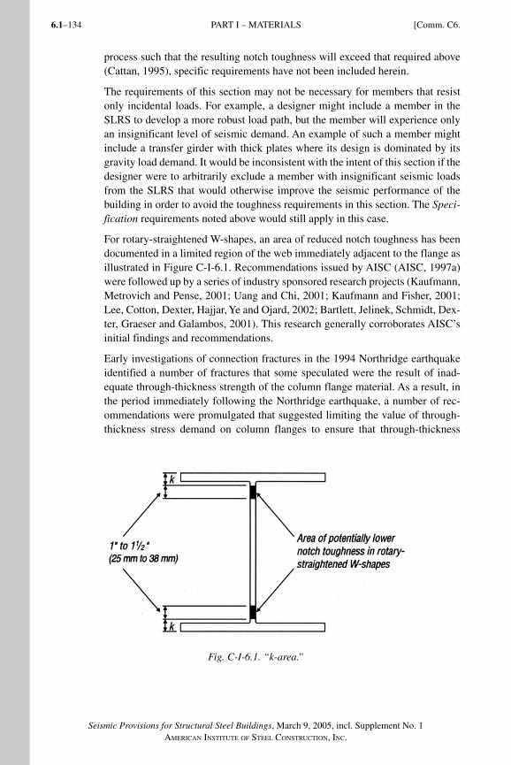
Seismic Provisions for Structural Steel Buildings, March 9, 2005, incl. Supplement No. 1AMERICAN INSTITUTE OF STEEL CONSTRUCTION, INC.
6.1–134
process such that the resulting notch toughness will exceed that required above (Cattan, 1995), specific requirements have not been included herein.
The requirements of this section may not be necessary for members that resist only incidental loads. For example, a designer might include a member in the SLRS to develop a more robust load path, but the member will experience only an insignificant level of seismic demand. An example of such a member might include a transfer girder with thick plates where its design is dominated by its gravity load demand. It would be inconsistent with the intent of this section if the designer were to arbitrarily exclude a member with insignificant seismic loads from the SLRS that would otherwise improve the seismic performance of the building in order to avoid the toughness requirements in this section. The Speci-fication requirements noted above would still apply in this case.
For rotary-straightened W-shapes, an area of reduced notch toughness has been documented in a limited region of the web immediately adjacent to the flange as illustrated in Figure C-I-6.1. Recommendations issued by AISC (AISC, 1997a) were followed up by a series of industry sponsored research projects (Kaufmann, Metrovich and Pense, 2001; Uang and Chi, 2001; Kaufmann and Fisher, 2001; Lee, Cotton, Dexter, Hajjar, Ye and Ojard, 2002; Bartlett, Jelinek, Schmidt, Dex-ter, Graeser and Galambos, 2001). This research generally corroborates AISC’s initial findings and recommendations.
Early investigations of connection fractures in the 1994 Northridge earthquake identified a number of fractures that some speculated were the result of inad-equate through-thickness strength of the column flange material. As a result, in the period immediately following the Northridge earthquake, a number of rec-ommendations were promulgated that suggested limiting the value of through-thickness stress demand on column flanges to ensure that through-thickness
Fig. C-I-6.1. “k-area.”
PART I – MATERIALS [Comm. C6.
SeismicProvComm1.indd 134SeismicProvComm1.indd 134 9/8/06 3:13:06 PM9/8/06 3:13:06 PMProcess BlackProcess Black
6.1–135
Seismic Provisions for Structural Steel Buildings, March 9, 2005, incl. Supplement No. 1AMERICAN INSTITUTE OF STEEL CONSTRUCTION, INC.
Comm. C7.] PART I – CONNECTIONS, JOINTS, AND FASTENERS
yielding did not initiate in the column flanges. This limit state often controlled the overall design of these connections. However, the actual cause for the frac-tures that were initially thought to be through-thickness failures of the column flange are now considered to be unrelated to this material property. Detailed fracture mechanics investigations conducted as part of the FEMA/SAC project confirm that damage initially identified as through thickness failures is likely to have occurred as a result of certain combinations of filler metal and base mate-rial strength and notch toughness, conditions of stress in the connection, and the presence of critical flaws in the welded joint. In addition to the analytical stud-ies, extensive through-thickness testing conducted specifically to determine the susceptibility to through thickness failures of modern column materials meeting ASTM A572, Grade 50 and ASTM A913, Grade 65 specifications did not result in significant through-thickness fractures (FEMA, 2000h).
In addition, none of the more than 100 full scale tests on “post-Northridge” con-nection details have demonstrated any through-thickness column fractures. This combined analytical and laboratory research clearly shows that due to the high restraint inherent in welded beam flange to column flange joints, the through thickness yield and tensile strengths of the column material are significantly elevated in the region of the connection. For the modern materials tested, these strengths significantly exceed those loads that can be delivered to the column by the beam flange. For this reason, no limits are suggested for the through-thickness strength of the base material by the FEMA/SAC program or in these Provisions.
The preceding discussion assumes that no significant laminations, inclusions or other discontinuities occur in regions adjacent to welded beam flange-to-column flange joints and other tee and corner joints. Appendix Q, Section Q5.2(2)(c), checks the integrity of this material after welding. A more conservative approach would be to ultrasonically test the material for laminations prior to welding. A similar requirement has been included in the Los Angeles City building code since 1973; however, in practice the base material prior to welding passes the ultrasonic examination, and interior defects, if any, are found only after heat-ing and cooling during the weld process. Should a concern exist, the ultrasonic inspection prior to welding should be conducted to ASTM A435 for plates and ASTM A898, level 1, for shapes.
C7. CONNECTIONS, JOINTS, AND FASTENERS
C7.1. ScopeThe requirement that design of a connection of a member in a seismic load re-sisting system (SLRS) ensures a ductile limit state has been moved from the sec-tion on bolted joints to the Scope section, since this requirement applies to both bolted and welded joints. Tension or shear fracture, bolt shear, and block shear rupture are examples of limit states that generally result in nonductile failure of connections. As such, these limit states are undesirable as the controlling limit state for connections that are part of the SLRS. Accordingly, it is required that
SeismicProvComm1.indd 135SeismicProvComm1.indd 135 9/8/06 3:13:07 PM9/8/06 3:13:07 PMProcess BlackProcess Black
Seismic Provisions for Structural Steel Buildings, March 9, 2005, incl. Supplement No. 1AMERICAN INSTITUTE OF STEEL CONSTRUCTION, INC.
6.1–136
connections be configured such that a ductile limit state in the member or connec-tion, such as yielding or bearing deformation, controls the available strength.
C7.2. Bolted JointsThe potential for full reversal of design load and the likelihood of inelastic defor-mations of members and/or connected parts necessitates that pretensioned bolts be used in bolted joints in the SLRS. However, earthquake motions are such that slip cannot and need not be prevented in all cases, even with slip-critical con-nections. Accordingly, the Provisions call for bolted joints to be proportioned as pretensioned bearing joints but with faying surfaces prepared as for Class A or better slip-critical connections. That is, bolted connections can be proportioned with available strengths for bearing connections as long as the faying surfaces are still prepared to provide a minimum slip coefficient, µ = 0.35. The resulting nominal amount of slip resistance will minimize damage in more moderate seis-mic events. This requirement is intended for joints where the faying surface is primarily subjected to shear. Where the faying surface is primarily subjected to tension or compression, for example, in a bolted end plate moment connection, the requirement on preparation of the faying surfaces may be relaxed.
To prevent excessive deformations of bolted joints due to slip between the con-nected plies under earthquake motions, the use of holes in bolted joints in the SLRS is limited to standard holes and short-slotted holes with the direction of the slot perpendicular to the line of force. Exceptions are provided for alternative hole types that are justified as a part of a tested assembly and for oversized holes in brace diagonals.
A change from the 2002 Provisions is the acceptance of the use of oversized holes in braced connections of diagonal members subject to certain limitations. As reported in FEMA 355D, bolted joints with oversized holes in tested moment connections were found to behave as full stiffness connections for most practical applications. Bracing connections with oversized holes in bolted connections should behave similarly. The design of the brace connections with oversized holes as slip-critical will provide additional tolerance for field connections, yet should remain as slip-resistant for most seismic events. If the bolts did slip in the oversized holes in an extreme situation, the connections should still behave similar to full stiffness connections. Interstory drifts may also increase slightly if bolts slip, and the effect of bolt slip should be considered in drift calcula-tions. In order to minimize the amount of slip, oversized holes for bolts should be limited to one ply of the connection. For large diameter bolts, the amount of slippage could also be minimized by limiting the bolt hole size to a maximum of x in. greater than the bolt diameter, rather than the full range permitted by the Specification. When using oversized holes with slip-critical bolts, the effect of the reduced slip capacities of bolts in oversized holes should be considered. The reduction of pretension results in a lower static slip load, but the overall behavior of connections with oversized holes has been shown to be similar to those with standard holes (Kulak, Fisher and Struik, 1987).
PART I – CONNECTIONS, JOINTS, AND FASTENERS [Comm. C7.
SeismicProvComm1.indd 136SeismicProvComm1.indd 136 9/8/06 3:13:07 PM9/8/06 3:13:07 PMProcess BlackProcess Black
6.1–137
Seismic Provisions for Structural Steel Buildings, March 9, 2005, incl. Supplement No. 1AMERICAN INSTITUTE OF STEEL CONSTRUCTION, INC.
Comm. C7.] PART I – CONNECTIONS, JOINTS, AND FASTENERS
To prevent excessive deformations of bolted joints due to bearing on the connect-ed material, the bearing strength is limited by the “deformation-considered” op-tion in Specification Section J3.10 (Rn = 2.4dtFu). The philosophical intent of this limitation in the Specification is to limit the bearing deformation to an approxi-mate maximum of 4 in. (6 mm). It should be recognized, however, that the actual bearing load in a seismic event may be much larger than that anticipated in design and the actual deformation of holes may exceed this theoretical limit. Nonethe-less, this limit should effectively minimize damage in moderate seismic events.
These provisions have expanded the prohibition of bolts in combination with welds resisting a common force. The 2002 provisions prohibited bolts and welds from sharing loads on a common faying surface. Due to the potential of full load reversal and the likelihood of inelastic deformations in connecting plate elements, bolts may exceed their slip resistances under significant seismic loads. Welds that are in a common shear plane to these bolts will likely not deform sufficiently to allow the bolts to slip into bearing, particularly if subject to load reversal. Consequently the welds will tend to resist the entire force and may fail if they were not designed as such. These provisions have been modified to pro-hibit bolts from sharing a common force with welds in all situations. While this would still prohibit sharing loads on a common faying surface it would also pro-hibit sharing of a common force between different elements in other conditions. For example, bracing connections at beam-to-column joints are often configured such that the vertical component of the brace is resisted by a combination of both the gusset and beam web connections to the columns (see Figures C-I-7.1a and C-I-7.1b). Since these two elements are in a common shear plane with limited deformation capability, if one element were welded and the other bolted, the welded joint would likely resist all the force. By making the connection of these elements to the column either both bolted or both welded, both elements would likely participate in resisting the force. Similarly, wide flange bracing connec-tions should not be designed such that bolted web connections share in resisting the axial loads with welded flanges (or vice versa).
Bolts in one element of a member may be designed to resist a force in one direc-tion while other elements may be connected by welds to resist a force in a different direction or shear plane. For example, a beam moment connected to a column may use welded flanges to transfer flexure and/or axial loads, while a bolted web connection transfers the beam shear. Similarly, column splices may transfer axial loads and/or flexure through flange welds with horizontal shear in the column web transferred through a bolted web connection. In both of these cases there should be adequate deformation capability between the flange and web connections to allow the bolts to resist loads in bearing independent of the welds.
The provisions do not prohibit the use of erection bolts on a field welded connec-tion such as a web shear tab in a wide flange moment connection. In this instance the bolts would resist the temporary erection loads, but the welds would need to be designed to resist the entire anticipated force in that element.
SeismicProvComm1.indd 137SeismicProvComm1.indd 137 9/8/06 3:13:07 PM9/8/06 3:13:07 PMProcess BlackProcess Black
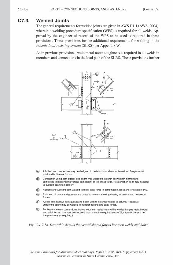
Seismic Provisions for Structural Steel Buildings, March 9, 2005, incl. Supplement No. 1AMERICAN INSTITUTE OF STEEL CONSTRUCTION, INC.
6.1–138
C7.3. Welded JointsThe general requirements for welded joints are given in AWS D1.1 (AWS, 2004), wherein a welding procedure specification (WPS) is required for all welds. Ap-proval by the engineer of record of the WPS to be used is required in these provisions. These provisions invoke additional requirements for welding in the seismic load resisting system (SLRS) per Appendix W.
As in previous provisions, weld metal notch toughness is required in all welds in members and connections in the load path of the SLRS. These provisions further
Fig. C-I-7.1a. Desirable details that avoid shared forces between welds and bolts.
PART I – CONNECTIONS, JOINTS, AND FASTENERS [Comm. C7.
SeismicProvComm1.indd 138SeismicProvComm1.indd 138 1/9/08 2:53:29 PM1/9/08 2:53:29 PM
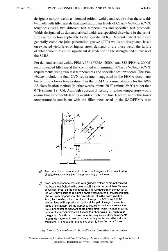
6.1–139
Seismic Provisions for Structural Steel Buildings, March 9, 2005, incl. Supplement No. 1AMERICAN INSTITUTE OF STEEL CONSTRUCTION, INC.
Comm. C7.] PART I – CONNECTIONS, JOINTS, AND FASTENERS
designate certain welds as demand critical welds, and require that these welds be made with filler metals that meet minimum levels of Charpy V-Notch (CVN) toughness using two different test temperatures and specified test protocols. Welds designated as demand critical welds are specified elsewhere in the provi-sions in the section applicable to the specific SLRS. Demand critical welds are generally complete-joint-penetration groove (CJP) welds so designated based on expected yield level or higher stress demand, or are those welds the failure of which would result in significant degradation in the strength and stiffness of the SLRS.
For demand critical welds, FEMA 350 (FEMA, 2000a) and 353 (FEMA, 2000d) recommended filler metal that complied with minimum Charpy V-Notch (CVN) requirements using two test temperatures and specified test protocols. The Pro-visions include the dual CVN requirement suggested in the FEMA documents but require a lower temperature than the FEMA recommendations for the AWS A5 classification method [in other words, minus 20 °F (minus 29 °C) rather than 0 °F (minus 18 °C)]. Although successful testing at either temperature would ensure that some ductile tearing would occur before final fracture, use of this lower temperature is consistent with the filler metal used in the SAC/FEMA tests
Fig. C-I-7.1b. Problematic bolted/welded member connections.
SeismicProvComm1.indd 139SeismicProvComm1.indd 139 9/8/06 3:13:09 PM9/8/06 3:13:09 PMProcess BlackProcess Black
Seismic Provisions for Structural Steel Buildings, March 9, 2005, incl. Supplement No. 1AMERICAN INSTITUTE OF STEEL CONSTRUCTION, INC.
6.1–140
and matches the filler metals commercially available and frequently used for such welds. The more critical CVN weld metal property is the minimum of 40 ft-lbs (54 J) at 70 °F (21 °C) following the procedure in Appendix X. Based on the FEMA recommendations, the engineer of record may consider applying the 40 ft-lbs (54 J) at 70 °F (21 °C) requirements to other critical welds.
In a structure with exposed structural steel, an unheated building, or a build-ing used for cold storage, the demand critical welds may be subject to service temperatures less than 50 °F (10 °C). In these cases the provisions require that the minimum qualification temperature for Appendix X be adjusted such that the test temperature for the Charpy V-Notch toughness qualification tests shall be no more than 20 °F (11 °C) above the lowest anticipated service temperature (LAST). The LAST should be determined from appropriate resources for the area or application. For example, weld metal in a structure with a lowest antici-pated service temperature of 0 °F (minus 18 °C) would need to be qualified at a temperature less than or equal to 20 °F (minus 7 °C).
All other welds in members and connections in the load path of the SLRS re-quire filler metal with a minimum specified CVN toughness of 20 ft-lb (27 J) at 0 °F (minus 18 °C). This is a relaxation from the previous provisions, which required 20 ft-lb (27 J) at minus 20 °F (minus 29 °C) for all welds. The require-ment in the previous provisions considered that FCAW and SMAW electrodes that met the lower test values were readily available, and therefore one common test temperature could be used for both the moment frame critical welds and the balance of welding in the SLRS. The nominal increase in test temperature still provides adequate notch toughness for filler welds in nondemand critical welds, while permitting other common notch-tough electrodes used for SAW and GMAW processes to be used. Welds carrying only gravity loads such as filler beam connections and welds for collateral members of the SLRS such as
deck welds, minor collectors, and lateral bracing do not require filler metal with notch toughness requirements. Following the manufacturer’s essential variables, either the AWS classification method in the AWS A5 specification or manufac-turer certification may be used to meet this CVN requirement.
It is not the intent of the Provisions to require project-specific CVN testing of either the welding procedure or any production welds. Further, these weld tough-ness requirements are not intended to apply to electric resistance welding (ERW) and submerged arc welding (SAW) when these welding processes are used in the production of hollow structural sections and pipe (ASTM A500 and A53/A53M). In addition, the control of heat input is not monitored unless specified.
These provisions delete the Appendix X production lot testing requirements for SMAW electrodes classified by AWS A5 specifications as E7018 and E8018, and also for GMAW solid electrodes when the CVN toughness determined per AWS classification test methods meets or exceeds 20 ft-lb (27 J) at temperatures less than or equal to minus 20 °F (minus 29 °C). The deposited filler metal of these electrodes routinely meets the CVN toughness requirements for demand critical welds and therefore the requirements for these electrodes are relaxed.
PART I – CONNECTIONS, JOINTS, AND FASTENERS [Comm. C7.
SeismicProvComm1.indd 140SeismicProvComm1.indd 140 9/8/06 3:13:10 PM9/8/06 3:13:10 PMProcess BlackProcess Black
6.1–141
Seismic Provisions for Structural Steel Buildings, March 9, 2005, incl. Supplement No. 1AMERICAN INSTITUTE OF STEEL CONSTRUCTION, INC.
Comm. C7.] PART I – CONNECTIONS, JOINTS, AND FASTENERS
C7.4. Protected ZoneThe FEMA/SAC testing has demonstrated the sensitivity of regions undergoing large inelastic strains to discontinuities caused by welding, rapid change of section, penetrations, or construction caused flaws. For this reason, operations that cause dis-continuities are prohibited in regions subject to large inelastic strains. These provi-sions designate these regions as protected zones. The protected zones are designated in the Provisions in the sections applicable to the designated type of system and in ANSI/AISC 358 (AISC, 2005a). The protected zones include moment frame hing-ing zones, links of EBFs, the ends and the center of SCBF braces, etc.
Not all regions experiencing inelastic deformation are designated protected zones; for example, the beam-column panel zone. It should be noted that yield level strains are not strictly limited to the plastic hinge zones and caution should also be exercised in creating discontinuities in these regions as well.
Many operations during fabrication, erection, and the subsequent work of other trades have the potential to create discontinuities in the seismic load resisting system. When located in the designated protected zone, such discontinuities are required to be repaired by the responsible subcontractor as required by the engineer of re-cord. Discontinuities should also be repaired in other regions of the seismic load resisting system when the presence of the discontinuity would be detrimental to its performance. The responsible subcontractor should propose a repair procedure for the approval of the engineer of record. Repair may be unnecessary for some discon-tinuities, subject to the approval of the engineer of record. The engineer of record should refer to AWS D1.1 and ASTM A6, Section 9 for guidance in establishing the acceptance criteria for repair of discontinuities. Outside the plastic hinge regions, AWS D1.1 requirements for repair of discontinuities should be applied.
C7.5. Continuity Plates and StiffenersThe provisions are intended to avoid welding into the k-area of hot-rolled shapes in highly restrained joints such as continuity plates and stiffeners. This would in-clude continuity plates in columns at moment connections and stiffeners in link beams. See Section C6.3 for discussion on k-area properties. The increased clip dimensions preclude the possibility of welding in these regions. (See Figures C-I-7.2a and b.) In addition, when groove welds are used, care should be used when preparing the joint termination near the member radius to enable quality welding for the full length of the joint. Weld tabs should not be used in the k-area.
Where practical, connections with groove or multi-pass fillet welds in members of the SLRS should also be avoided in the k-area. A common example is welding of doublers in panel zones. Alternative details for doublers that avoid welding in the k-area can be found in Figure C-I-9.3. Where welding in the k-area cannot be avoided, or has been done in error, the k-area should be inspected per Appendix Q, Section Q5.2. The section is not intended to prevent welding of minor connec-tion elements such as shear tabs near the k-area. These elements generally have small weld sizes and minimal restraint since they are not connected concurrently with the flange of the wide flange.
SeismicProvComm1.indd 141SeismicProvComm1.indd 141 9/8/06 3:13:10 PM9/8/06 3:13:10 PMProcess BlackProcess Black
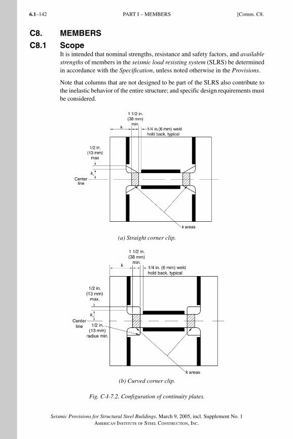
Seismic Provisions for Structural Steel Buildings, March 9, 2005, incl. Supplement No. 1AMERICAN INSTITUTE OF STEEL CONSTRUCTION, INC.
6.1–142
C8. MEMBERS
C8.1 ScopeIt is intended that nominal strengths, resistance and safety factors, and available strengths of members in the seismic load resisting system (SLRS) be determined in accordance with the Specification, unless noted otherwise in the Provisions.
Note that columns that are not designed to be part of the SLRS also contribute to the inelastic behavior of the entire structure; and specific design requirements must be considered.
(a) Straight corner clip.
(b) Curved corner clip.
Fig. C-I-7.2. Configuration of continuity plates.
PART I – MEMBERS [Comm. C8.
SeismicProvComm1.indd 142SeismicProvComm1.indd 142 9/8/06 3:13:10 PM9/8/06 3:13:10 PMProcess BlackProcess Black
6.1–143
Seismic Provisions for Structural Steel Buildings, March 9, 2005, incl. Supplement No. 1AMERICAN INSTITUTE OF STEEL CONSTRUCTION, INC.
Comm. C8.] PART I – MEMBERS
C8.2. Classification of Sections for Local BucklingTo provide for reliable inelastic deformations in those SLRS that require high levels of inelasticity, the member flanges must be continuously connected to the web(s) and the width-thickness ratios of compression elements should be less than or equal to those that are resistant to local buckling when stressed into the inelastic range. Although the limiting width-thickness ratios for compact mem-bers, λp, given in Specification Table B4.1, are sufficient to prevent local buck-ling before onset of strain-hardening, the available test data suggest that these limits are not adequate for the required inelastic performance in several of the SLRS. The limiting width-thickness ratios for seismically compact members, λps, given in Table I-8-1 are deemed adequate for ductilities to 6 or 7 (Sawyer, 1961; Lay, 1965; Kemp, 1986; Bansal, 1971). The limiting width-thickness ra-tios for webs in flexural compression have been modified (Uang and Fan, 2001) to comply with the recommendations in FEMA 350 (FEMA, 2000a). Provisions for special moment frames (SMF), members in the special segment of special truss moment frames (STMF), special concentrically braced frames (SCBF), the links in eccentrically braced frames (EBF), and H-pile design specifically reference Table I-8-1.
Diagonal web members used in the special segments of STMF systems are lim-ited to flat bars only at this time because of their proven high ductility without buckling. The specified limiting width-thickness ratio of 2.5 in Table I-8-1 does not vary with Fy and is intended to be a practical method to limit the aspect ratio of flat bar cross-sections.
During the service life of a steel H-pile it is primarily subjected to axial com-pression and acts as an axially loaded column. Therefore, the b/t ratio limita-tions given in Table B4.1 of the Specification should suffice. During a major earthquake, because of lateral movements of pile cap and foundation, the steel H-pile becomes a beam-column and may have to resist large bending moments and uplift. Cyclic tests (Astaneh-Asl and Ravat, 1997) indicated that local buck-ling of piles satisfying the width-thickness limitations in Table I-8-1 occurs after many cycles of loading. In addition, this local buckling did not have much effect on the cyclic performance of the pile during cyclic testing or after cyclic testing stopped and the piles were once again under only axial load.
In Section 6.2, the expected yield strength, RyFy, of the material used in a mem-ber is required for the purpose of determining the effect of the actual member strength on its connections to other members of the seismic load resisting sys-tem. The width-thickness requirements in Table I-8-1, calculated using specified minimum yield stress, are expected to permit inelastic behavior without local buckling and need not be computed using the expected yield strength.
C8.3. Column StrengthIt is imperative that columns that are part of the SLRS have adequate strength to avoid global buckling or tensile fracture. Since the late 1980s, the Seismic Provisions and other codes and standards have included requirements that are
SeismicProvComm1.indd 143SeismicProvComm1.indd 143 9/8/06 3:13:11 PM9/8/06 3:13:11 PMProcess BlackProcess Black
Seismic Provisions for Structural Steel Buildings, March 9, 2005, incl. Supplement No. 1AMERICAN INSTITUTE OF STEEL CONSTRUCTION, INC.
6.1–144
essentially identical to those included in Section 8.3. The required forces for de-sign of the columns are intended to represent reasonable limits on the axial forc-es that can be imposed, and design for these forces is expected to prevent global column failure. These axial forces are permitted to be applied without consider-ation of concurrent bending moments that may occur. Additionally, the column design using these forces is typically checked using K = 1.0. This approach is based on the recognition that in the SLRS, column bending moments would be largest at the column ends and would normally result in reverse curvature in the column. This being the case, the bending moments would not be contributory to column buckling, and the assumption of K = 1 would be conservative.
Clearly, the above-described approach provides no assurance that columns will not yield and, certainly, the combination of axial load and bending is often capa-ble of causing yielding at the ends of columns. Column yielding may be caused by a combination of high bending moments and modest axial loads, as is normal in moment frames or by a combination of high axial load and bending due to the end rotations that occur in braced frame structures. While yielding of columns may result in damage that is significant and difficult to repair, it is judged that, in general, it will not result in column fractures or global buckling, either of which would threaten life safety.
Although the provisions in Section 8.3 are believed to provide reasonable assur-ance of adequate performance, it should be recognized that these are minimum standards and where higher levels of performance, or greater levels of reliability are merited, several additional concerns should be considered:
(1) Nonlinear analyses often indicate conditions wherein column end moments are not reversed and may be contributory to buckling.
(2) There is little available research on column performance under the com-bination of very high axial load (in the range of 0.6 – 0.7Py and higher) in conjunction with significant end rotations. Research on this condition is recommended for the future.
Realistic soil capacities must be used when determining the limiting resistance of the foundation to overturning uplift.
C8.4. Column Splices
C8.4a. GeneralExcept for moment frames, the available strength of a column splice is required to equal or exceed both the required strength determined in Section 8.3 and the required strength for axial, flexural and shear effects at the splice location deter-mined from load combinations stipulated by the applicable building code.
Column splices should be located away from the beam-to-column connec-tion to reduce the effects of flexure. For typical buildings, the 4 ft (1.2 m) mini-mum distance requirement will control. When splices are located 4 to 5 ft (1.2 to 1.5 m) above the floor level, field erection and construction of the column splice will generally be simplified due to improved accessibility and convenience. In
PART I – MEMBERS [Comm. C8.
SeismicProvComm1.indd 144SeismicProvComm1.indd 144 9/8/06 3:13:11 PM9/8/06 3:13:11 PMProcess BlackProcess Black
6.1–145
Seismic Provisions for Structural Steel Buildings, March 9, 2005, incl. Supplement No. 1AMERICAN INSTITUTE OF STEEL CONSTRUCTION, INC.
Comm. C8.] PART I – MEMBERS
general, it is recommended that the splice be within the middle third of the story height. For less typical buildings, where the floor-to-floor height is insufficient to accommodate this requirement, the splice should be placed as close as prac-ticable to the midpoint of the clear distance between the finished floor and the bottom flange of the beam above. It is not intended that these column splice requirements be in conflict with applicable safety regulations, such as the OSHA Safety Standards for Steel Erection developed by the Steel Erection Negotiated Rulemaking Advisory Committee (SENRAC).
Partial-joint-penetration groove welded splices of thick column flanges exhibit virtually no ductility under tensile loading (Popov and Stephen, 1977; Bruneau, Mahin and Popov, 1987). Consequently, column splices made with partial-joint-penetration groove welds require a 100 percent increase in required strength and must be made using weld metal with minimum Charpy V-Notch (CVN) tough-ness properties.
The calculation of the minimum available strength in Section 8.4a(2) includes the ratio Ry. This results in a minimum available strength that is not less than 50 percent of the expected yield strength of the column flanges. A complete-joint-penetration (CJP) groove weld may be considered as satisfying this requirement.
The possible occurrence of tensile loads in column splices utilizing partial-joint-penetration (PJP) groove welds during a maximum considered earthquake should be evaluated. When tensile loads are possible, it is suggested that some restraint be provided against relative lateral movement between the spliced column shafts. For example, this can be achieved with the use of flange splice plates. Alternatively, web splice plates that are wide enough to maintain the gen-eral alignment of the spliced columns can be used. Shake-table experiments have shown that when columns that are unattached at the base reseat themselves after lifting, the perform ance of a steel frame remains tolerable (Huckelbridge and Clough, 1977).
These provisions are applicable to common frame configurations. Additional considerations may be necessary when flexure dominates over axial compres-sion in columns in moment frames, and in end columns of tall narrow frames where overturning forces can be very significant. The designer should review the conditions found in columns in buildings with tall story heights, when large changes in column sizes occur at the splice, or when the possibility of column buckling in single curvature over multiple stories exists. In these and similar cases, special column splice requirements may be necessary for minimum avail-able strength and/or detailing.
Where CJP groove welds are not used, the connection is likely to be a PJP groove weld. The unwelded portion of the PJP groove weld forms a crack-like notch that induces stress concentrations. A PJP groove weld made from one side would produce an edge crack-like notch (Barsom and Rolfe, 1999). A PJP groove weld made from both sides would produce a buried crack-like notch. The strength of such crack-like notches may be computed by using fracture
SeismicProvComm1.indd 145SeismicProvComm1.indd 145 9/8/06 3:13:11 PM9/8/06 3:13:11 PMProcess BlackProcess Black
Seismic Provisions for Structural Steel Buildings, March 9, 2005, incl. Supplement No. 1AMERICAN INSTITUTE OF STEEL CONSTRUCTION, INC.
6.1–146
mechanics methodology. Depending on the specific characteristics of the partic-ular design configuration, geometry and deformation, the analysis may require elastic-plastic or plastic finite element analysis of the joint. The accuracy of the computed strength will depend on the finite element model and mesh size used, the assumed strength and fracture toughness of the base metal, heat affected zone and weld metal, and on the residual stress magnitude and distribution in the joint.
Column web splices should be concentric with the column loads. Bolted column web splices are required to have connection plates on both sides of the web to minimize eccentricities.
C8.4b. Columns Not Part of the Seismic Load Resisting SystemInelastic analyses (FEMA, 2000f; FEMA, 2000g) of moment frame buildings have shown the importance of the columns that are not part of the SLRS in helping to distribute the seismic shears between the floors. Even columns that have beam connections considered to be pinned connections may develop large bending moments and shears due to nonuniform drifts of adjacent levels. For this reason, it is recommended that splices of such columns be adequate to develop the shear forces corresponding to these large column moments in both orthogo-nal directions.
FEMA 350 (FEMA, 2000a) recommends that, “Splices of columns that are not part of the Seismic Load Resisting System should be made in the center one-third of the column height, and should have sufficient shear capacity in both orthogonal directions to maintain the alignment of the column at the maximum shear force that the column is capable of producing.” The corresponding com-mentary suggests that this shear should be calculated assuming plastic hinges at the ends of the columns in both orthogonal directions.
Further review (Krawinkler, 2001) of nonlinear analyses cited in FEMA 355C (FEMA, 2000d) showed that, in general, shears in such columns will be less than one-half of the shear calculated from 2Mpc /H. For this reason, Section 8.4b requires that the calculated shear in the splices be not less than Mpc /H.
Bolted web connections are preferred by many engineers and contractors be-cause they have advantages for erection, and, when plates are placed on both sides of the web, they are expected to maintain alignment of the column in the event of a flange splice fracture. PJP groove welded webs are not recommended, because fracture of a flange splice would likely lead to fracture of the web splice, considering the stress concentrations inherent in such welded joints.
C8.5. Column BasesColumn bases must have adequate strength to permit the expected ductile behav-ior for which the system is designed in order for the anticipated performance to be achieved.
PART I – MEMBERS [Comm. C8.
SeismicProvComm1.indd 146SeismicProvComm1.indd 146 9/8/06 3:13:12 PM9/8/06 3:13:12 PMProcess BlackProcess Black
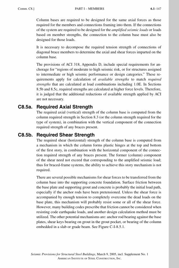
6.1–147
Seismic Provisions for Structural Steel Buildings, March 9, 2005, incl. Supplement No. 1AMERICAN INSTITUTE OF STEEL CONSTRUCTION, INC.
Comm. C8.] PART I – MEMBERS
Column bases are required to be designed for the same axial forces as those required for the members and connections framing into them. If the connections of the system are required to be designed for the amplified seismic loads or loads based on member strengths, the connection to the column base must also be designed for those loads.
It is necessary to decompose the required tension strength of connections of diagonal brace members to determine the axial and shear forces imparted on the column base.
The provisions of ACI 318, Appendix D, include special requirements for an-chorage for “regions of moderate to high seismic risk, or for structures assigned to intermediate or high seismic performance or design categories.” These re-quirements apply for calculation of available strengths to match required strengths that are calculated at load combinations including 1.0E. In Sections 8.5b and 8.5c, required strengths are calculated at higher force levels. Therefore, it is judged that the additional reductions of available strength applied by ACI are not necessary.
C8.5a. Required Axial StrengthThe required axial (vertical) strength of the column base is computed from the column required strength in Section 8.3 (or the column strength required for the type of system), in combination with the vertical component of the connection required strength of any braces present.
C8.5b. Required Shear StrengthThe required shear (horizontal) strength of the column base is computed from a mechanism in which the column forms plastic hinges at the top and bottom of the first story, in combination with the horizontal component of the connec-tion required strength of any braces present. The former (column) component of the shear need not exceed that corresponding to the amplified seismic load; thus for braced-frame systems, the ability to achieve this story mechanism is not required.
There are several possible mechanisms for shear forces to be transferred from the column base into the supporting concrete foundation. Surface friction between the base plate and supporting grout and concrete is probably the initial load path, especially if the anchor rods have been pretensioned. Unless the shear force is accompanied by enough tension to completely overcome the dead loads on the base plate, this mechanism will probably resist some or all of the shear force. However, many building codes prescribe that friction cannot be considered when resisting code earthquake loads, and another design calculation method must be utilized. The other potential mechanisms are: anchor rod bearing against the base plates, shear keys bearing on grout in the grout pocket, or bearing of the column embedded in a slab or grade beam. See Figure C-I-8.5.1.
SeismicProvComm1.indd 147SeismicProvComm1.indd 147 9/8/06 3:13:12 PM9/8/06 3:13:12 PMProcess BlackProcess Black
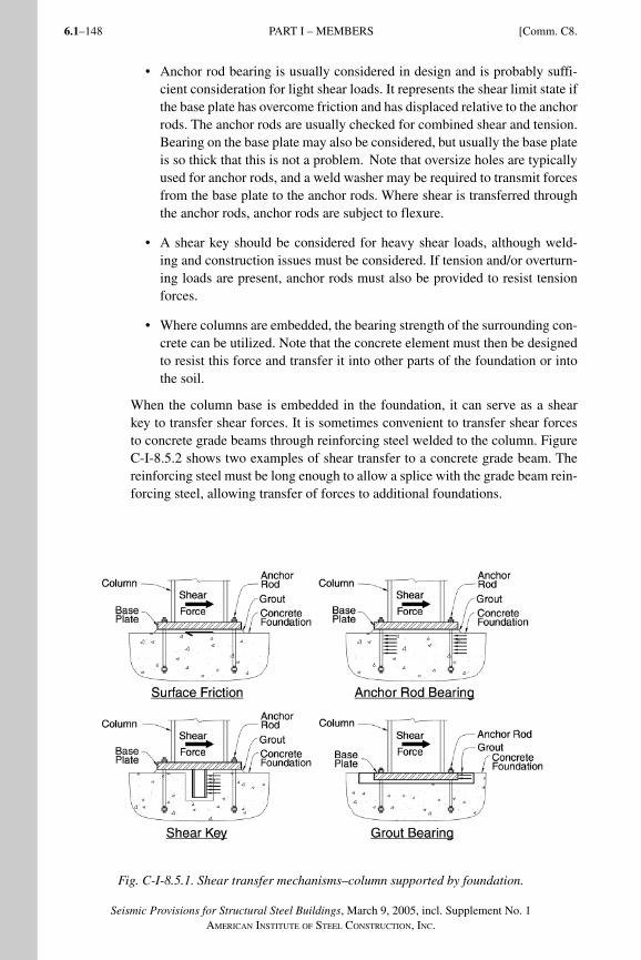
Seismic Provisions for Structural Steel Buildings, March 9, 2005, incl. Supplement No. 1AMERICAN INSTITUTE OF STEEL CONSTRUCTION, INC.
6.1–148
• Anchor rod bearing is usually considered in design and is probably suffi-cient consideration for light shear loads. It represents the shear limit state if the base plate has overcome friction and has displaced relative to the anchor rods. The anchor rods are usually checked for combined shear and tension. Bearing on the base plate may also be considered, but usually the base plate is so thick that this is not a problem. Note that oversize holes are typically used for anchor rods, and a weld washer may be required to transmit forces from the base plate to the anchor rods. Where shear is transferred through the anchor rods, anchor rods are subject to flexure.
• A shear key should be considered for heavy shear loads, although weld-ing and construction issues must be considered. If tension and/or overturn-ing loads are present, anchor rods must also be provided to resist tension forces.
• Where columns are embedded, the bearing strength of the surrounding con-crete can be utilized. Note that the concrete element must then be designed to resist this force and transfer it into other parts of the foundation or into the soil.
When the column base is embedded in the foundation, it can serve as a shear key to transfer shear forces. It is sometimes convenient to transfer shear forces to concrete grade beams through reinforcing steel welded to the column. Figure C-I-8.5.2 shows two examples of shear transfer to a concrete grade beam. The reinforcing steel must be long enough to allow a splice with the grade beam rein-forcing steel, allowing transfer of forces to additional foundations.
Fig. C-I-8.5.1. Shear transfer mechanisms–column supported by foundation.
PART I – MEMBERS [Comm. C8.
SeismicProvComm1.indd 148SeismicProvComm1.indd 148 9/8/06 3:13:12 PM9/8/06 3:13:12 PMProcess BlackProcess Black
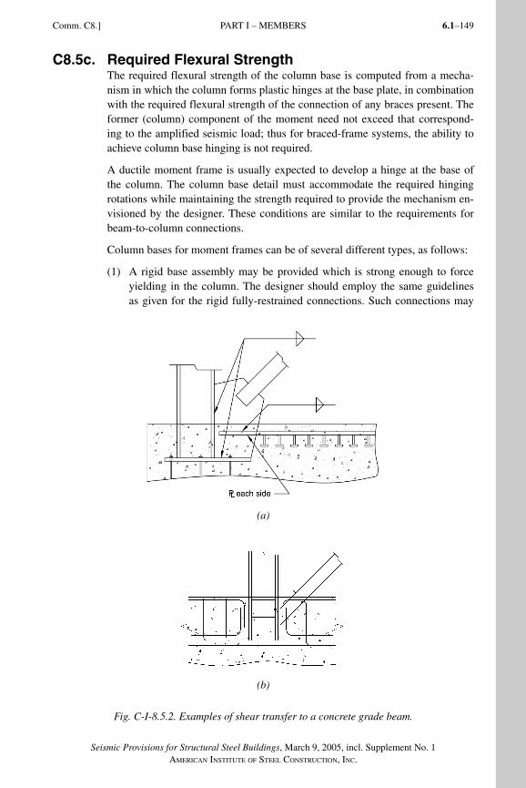
6.1–149
Seismic Provisions for Structural Steel Buildings, March 9, 2005, incl. Supplement No. 1AMERICAN INSTITUTE OF STEEL CONSTRUCTION, INC.
Comm. C8.] PART I – MEMBERS
C8.5c. Required Flexural StrengthThe required flexural strength of the column base is computed from a mecha-nism in which the column forms plastic hinges at the base plate, in combination with the required flexural strength of the connection of any braces present. The former (column) component of the moment need not exceed that correspond-ing to the amplified seismic load; thus for braced-frame systems, the ability to achieve column base hinging is not required.
A ductile moment frame is usually expected to develop a hinge at the base of the column. The column base detail must accommodate the required hinging rotations while maintaining the strength required to provide the mechanism en-visioned by the designer. These conditions are similar to the requirements for beam-to-column connections.
Column bases for moment frames can be of several different types, as follows:
(1) A rigid base assembly may be provided which is strong enough to force yielding in the column. The designer should employ the same guidelines as given for the rigid fully-restrained connections. Such connections may
(a)
(b)
Fig. C-I-8.5.2. Examples of shear transfer to a concrete grade beam.
SeismicProvComm1.indd 149SeismicProvComm1.indd 149 9/8/06 3:13:13 PM9/8/06 3:13:13 PMProcess BlackProcess Black
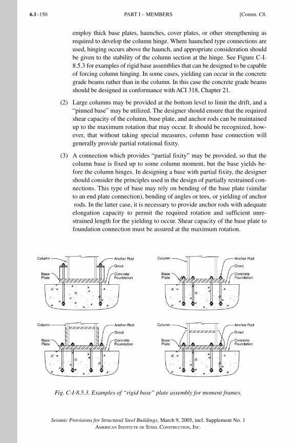
Seismic Provisions for Structural Steel Buildings, March 9, 2005, incl. Supplement No. 1AMERICAN INSTITUTE OF STEEL CONSTRUCTION, INC.
6.1–150
employ thick base plates, haunches, cover plates, or other strengthening as required to develop the column hinge. Where haunched type connections are used, hinging occurs above the haunch, and appropriate consideration should be given to the stability of the column section at the hinge. See Figure C-I-8.5.3 for examples of rigid base assemblies that can be designed to be capable of forcing column hinging. In some cases, yielding can occur in the concrete grade beams rather than in the column. In this case the concrete grade beams should be designed in conformance with ACI 318, Chapter 21.
(2) Large columns may be provided at the bottom level to limit the drift, and a “pinned base” may be utilized. The designer should ensure that the required shear capacity of the column, base plate, and anchor rods can be maintained up to the maximum rotation that may occur. It should be recognized, how-ever, that without taking special measures, column base connection will generally provide partial rotational fixity.
(3) A connection which provides “partial fixity” may be provided, so that the column base is fixed up to some column moment, but the base yields be-fore the column hinges. In designing a base with partial fixity, the designer should consider the principles used in the design of partially restrained con-nections. This type of base may rely on bending of the base plate (similar to an end plate connection), bending of angles or tees, or yielding of anchor rods. In the latter case, it is necessary to provide anchor rods with adequate elongation capacity to permit the required rotation and sufficient unre-strained length for the yielding to occur. Shear capacity of the base plate to foundation connection must be assured at the maximum rotation.
Fig. C-I-8.5.3. Examples of “rigid base” plate assembly for moment frames.
PART I – MEMBERS [Comm. C8.
SeismicProvComm1.indd 150SeismicProvComm1.indd 150 9/8/06 3:13:13 PM9/8/06 3:13:13 PMProcess BlackProcess Black
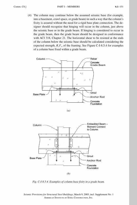
6.1–151
Seismic Provisions for Structural Steel Buildings, March 9, 2005, incl. Supplement No. 1AMERICAN INSTITUTE OF STEEL CONSTRUCTION, INC.
Comm. C8.] PART I – MEMBERS
(4) The column may continue below the assumed seismic base (for example, into a basement, crawl space, or grade beam) in such a way that the column’s fixity is assured without the need for a rigid base plate connection. The de-signer should recognize that hinging will occur in the column, just above the seismic base or in the grade beam. If hinging is considered to occur in the grade beam, then the grade beam should be designed in conformance with ACI 318, Chapter 21. The horizontal shear to be resisted at the ends of the column below the seismic base should be calculated considering the expected strength, RyFy, of the framing. See Figure C-I-8.5.4 for examples of a column base fixed within a grade beam.
(a)
(b)
Fig. C-I-8.5.4. Examples of column base fixity in a grade beam.
SeismicProvComm1.indd 151SeismicProvComm1.indd 151 9/8/06 3:13:14 PM9/8/06 3:13:14 PMProcess BlackProcess Black
Seismic Provisions for Structural Steel Buildings, March 9, 2005, incl. Supplement No. 1AMERICAN INSTITUTE OF STEEL CONSTRUCTION, INC.
6.1–152
For both braced frame and moment frame column bases, the designer should consider the base connection as similar to a beam-to-column connection and ap-ply similar principles of design and detailing. However, there are also significant differences that must be considered:
(1) Long anchor rods embedded in concrete will strain much more than the steel bolts or welds of the beam-to-column connections. The elonga-tion of these anchor rods may contribute to frame drift and this should be considered.
(2) Column base plates are bearing on grout or concrete that is more compress-ible than the column flanges of beam-to-column connections.
(3) Column base connections have significantly more longitudinal load in the plane of the flanges and less transverse load in the plane of the web, when compared to beam-to-column connections.
(4) The shear mechanism between the column base and grout or concrete is different from the shear mechanism between beam end plate and column flange.
(5) The AISC standard column base anchor rod hole diameter is different from AISC standard steel-to-steel bolt holes.
(6) Foundation rocking and rotation may be an issue, especially for isolated column footings.
The column base connection is one of the most important elements in steel struc-tures. Damage at column bases during past earthquakes has been reported by many observers (Northridge Reconnaissance Team, 1996; Midorikawa, Hasega-wa, Mukai, Nishiyama, Fukuta and Yamanouchi, 1997). Seismic design practice for this class of connections has not been well developed (DeWolf and Ricker, 1990; Drake and Elkin, 1999) mainly because of the rather limited number of analytical and experimental studies that have been carried out to-date (DeWolf and Sarisley, 1980; Picard and Beaulieu, 1985; Thambiratnam and Paramasivam, 1986; Sato and Kamagata, 1988; Astaneh-Asl, Bergsma and Shen, 1992; Tar-gowski, Lamblin and Guerlement, 1993; Ermopoulos and Stamatopoulos, 1996; Jaspart and Vandegans, 1998; Stojadinovic, Spacone, Goel and Kwon, 1998; Burda and Itani, 1999; Adany, Calado and Dunai, 2000).
Most of the experimental studies have been performed on reduced-scale speci-mens representing basic types of connections simulating a column welded to an exposed base plate, which in turn is connected to a concrete foundation through anchor rods. Test specimens have been subjected to axial loading combined with cyclic bending to simulate the column base behavior in moment frames. Two recent studies (Fahmy, Stojadinovic and Goel, 2000; Lee and Goel, 2001) have noted the importance of weld metal toughness and axis of bending of wide flange column sections on ductility and energy dissipation capacity of the test specimens. Also, relative strength and stiffness of the base plate and anchor rods can significantly influence the stress distribution and failure modes. The
PART I – MEMBERS [Comm. C8.
SeismicProvComm1.indd 152SeismicProvComm1.indd 152 9/8/06 3:13:15 PM9/8/06 3:13:15 PMProcess BlackProcess Black
6.1–153
Seismic Provisions for Structural Steel Buildings, March 9, 2005, incl. Supplement No. 1AMERICAN INSTITUTE OF STEEL CONSTRUCTION, INC.
Comm. C8.] PART I – MEMBERS
performance of the base connection also depends on the cyclic performance of the anchors and the surrounding concrete (Klingner and Graces, 2001).
Many different types of column base connections are used in current practice. Much research work is needed in order to better understand their behavior under seismic loading and to formulate improved design procedures. Designers should use caution and good judgment in design and detailing in order to achieve desired strength, stiffness, and ductility of this very important class of connections.
C8.6. H-PilesThe provisions on seismic design of H-piles are based on the data collected on the actual behavior of H-piles during recent earthquakes, including the 1994 Northridge earthquake (Astaneh-Asl, Bolt, McMullin, Donikaian, Modjtahedi and Cho, 1994) and the results of cyclic tests of full-scale pile tests (Astaneh-Asl and Ravat, 1997). In the test program, five full size H-piles with reinforced con-crete pile caps were subjected to realistic cyclic vertical and horizontal displace-ments expected in a major earthquake. Three specimens were vertical piles and two specimens were batter piles. The tests established that during cyclic loading for all three vertical pile specimens a very ductile and stable plastic hinge formed in the steel pile just below the reinforced concrete pile cap. When very large inelastic cycles were applied, local buckling of flanges within the plastic hinge area occurred. Eventually, low cycle fatigue fracture of flanges or overall buck-ling of the pile occurred. However, before the piles experienced fracture through locally buckled areas, vertical piles tolerated from 40 to 65 large inelastic cyclic vertical and horizontal displacements with rotation of the plastic hinge exceed-ing 0.06 radian for more than 20 cycles.
C8.6a. Design of H-PilesPrior to an earthquake, piles, particularly vertical piles, are primarily subjected to gravity axial load. During an earthquake, piles are subjected to horizontal and vertical displacements as shown in Figure C-I-8.6.1. The horizontal and vertical displacements of piles generate axial load (compression and possibly uplift ten-sion), bending moment, and shear in the pile.
During tests of H-piles, realistic cyclic horizontal and vertical displacements were applied to the pile specimens. Figure C-I-8.6.2 shows test results in terms of axial load and bending moment for one of the specimens. Based on perfor-mance of test specimens, it was concluded that H-piles should be designed fol-lowing the provisions of the Specification regarding members subjected to com-bined loads.
C8.6b. Battered H-PilesThe vertical pile specimens demonstrated very large cyclic ductility as well as considerable energy dissipation capacity. A case study of performance of H-piles during the 1994 Northridge earthquake (Astaneh-Asl and others, 1994) indicated excellent performance for pile groups with vertical piles only. However, the
SeismicProvComm1.indd 153SeismicProvComm1.indd 153 9/8/06 3:13:15 PM9/8/06 3:13:15 PMProcess BlackProcess Black
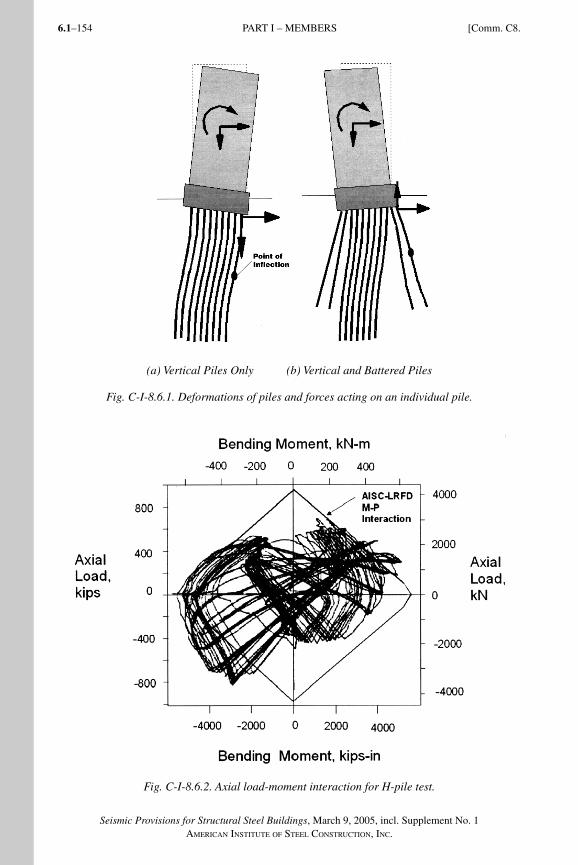
Seismic Provisions for Structural Steel Buildings, March 9, 2005, incl. Supplement No. 1AMERICAN INSTITUTE OF STEEL CONSTRUCTION, INC.
6.1–154
(a) Vertical Piles Only (b) Vertical and Battered Piles
Fig. C-I-8.6.1. Deformations of piles and forces acting on an individual pile.
Fig. C-I-8.6.2. Axial load-moment interaction for H-pile test.
PART I – MEMBERS [Comm. C8.
SeismicProvComm1.indd 154SeismicProvComm1.indd 154 9/8/06 3:13:15 PM9/8/06 3:13:15 PMProcess BlackProcess Black
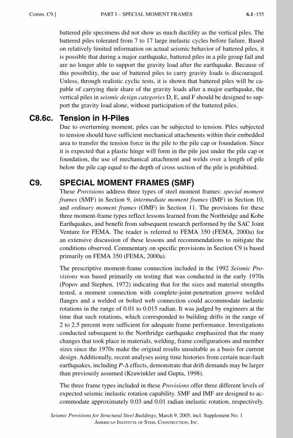
6.1–155
Seismic Provisions for Structural Steel Buildings, March 9, 2005, incl. Supplement No. 1AMERICAN INSTITUTE OF STEEL CONSTRUCTION, INC.
Comm. C9.] PART I – SPECIAL MOMENT FRAMES
battered pile specimens did not show as much ductility as the vertical piles. The battered piles tolerated from 7 to 17 large inelastic cycles before failure. Based on relatively limited information on actual seismic behavior of battered piles, it is possible that during a major earthquake, battered piles in a pile group fail and are no longer able to support the gravity load after the earthquake. Because of this possibility, the use of battered piles to carry gravity loads is discouraged. Unless, through realistic cyclic tests, it is shown that battered piles will be ca-pable of carrying their share of the gravity loads after a major earthquake, the vertical piles in seismic design categories D, E, and F should be designed to sup-port the gravity load alone, without participation of the battered piles.
C8.6c. Tension in H-PilesDue to overturning moment, piles can be subjected to tension. Piles subjected to tension should have sufficient mechanical attachments within their embedded area to transfer the tension force in the pile to the pile cap or foundation. Since it is expected that a plastic hinge will form in the pile just under the pile cap or foundation, the use of mechanical attachment and welds over a length of pile below the pile cap equal to the depth of cross section of the pile is prohibited.
C9. SPECIAL MOMENT FRAMES (SMF)These Provisions address three types of steel moment frames: special moment frames (SMF) in Section 9, intermediate moment frames (IMF) in Section 10, and ordinary moment frames (OMF) in Section 11. The provisions for these three moment-frame types reflect lessons learned from the Northridge and Kobe Earthquakes, and benefit from subsequent research performed by the SAC Joint Venture for FEMA. The reader is referred to FEMA 350 (FEMA, 2000a) for an extensive discussion of these lessons and recommendations to mitigate the conditions observed. Commentary on specific provisions in Section C9 is based primarily on FEMA 350 (FEMA, 2000a).
The prescriptive moment-frame connection included in the 1992 Seismic Pro-visions was based primarily on testing that was conducted in the early 1970s (Popov and Stephen, 1972) indicating that for the sizes and material strengths tested, a moment connection with complete-joint-penetration groove welded flanges and a welded or bolted web connection could accommodate inelastic rotations in the range of 0.01 to 0.015 radian. It was judged by engineers at the time that such rotations, which corresponded to building drifts in the range of 2 to 2.5 percent were sufficient for adequate frame performance. Investigations conducted subsequent to the Northridge earthquake emphasized that the many changes that took place in materials, welding, frame configurations and member sizes since the 1970s make the original results unsuitable as a basis for current design. Additionally, recent analyses using time histories from certain near-fault earthquakes, including P-Δ effects, demonstrate that drift demands may be larger than previously assumed (Krawinkler and Gupta, 1998).
The three frame types included in these Provisions offer three different levels of expected seismic inelastic rotation capability. SMF and IMF are designed to ac-commodate approximately 0.03 and 0.01 radian inelastic rotation, respectively.
SeismicProvComm1.indd 155SeismicProvComm1.indd 155 9/8/06 3:13:16 PM9/8/06 3:13:16 PMProcess BlackProcess Black
Seismic Provisions for Structural Steel Buildings, March 9, 2005, incl. Supplement No. 1AMERICAN INSTITUTE OF STEEL CONSTRUCTION, INC.
6.1–156
OMF are designed to remain essentially elastic and are assumed to have only very small inelastic demands. It is assumed that the elastic drift of typical mo-ment frames is usually in the range of 0.01 radian and that the inelastic rotation of the beams is approximately equal to the inelastic drift. These frames are as-sumed to accommodate total interstory drifts in the range of 0.04, 0.02, and 0.01 radian, respectively.
Although it is common to visualize inelastic rotations in moment frames oc-curring at beam or column “hinges,” analyses and testing demonstrate that the inelastic rotations actually combine flexural deformations at the hinges, shear deformations of the panel zones, and deformations from other sources depend-ing on the configuration unless the column webs are unusually thick. The con-tribution of panel zone deformation to inelastic rotation is considered benefi-cial, provided that it neither leads to significant local column flange bending at the beam-flange-to-column-flange welds nor to significant column damage. Currently, the amount of panel zone deformation that a given connection will have and how much it will accommodate appears to be most reliably determined by testing.
Based upon the recommendations in FEMA 350 (FEMA, 2000a), the Provisions require that connections in SMF and IMF be qualified for use by testing. (Note that the IMF as defined in these Provisions is equivalent to the OMF as defined in FEMA 350.) The AISC Prequalified Connections for Special and Intermedi-ate Steel Moment Frames for Seismic Applications (AISC, 2005a) provides a limited number of prequalified connections to employ in SMF and IMF. It is not the intent of the Provisions to require specific tests for each design, except where the design is sufficiently unique that there are no published or otherwise available tests adequately representing the proposed configuration. For many commonly employed combinations of beam and column sizes, there are read-ily available test reports in publications of AISC, FEMA and others, including FEMA 355D (FEMA, 2000e) and (Gross, Engelhardt, Uang, Kasai and Iwan-kiw, 1999). Qualification testing is not required for OMF connections, which may be proportioned following a set of prescriptive design rules that have been demonstrated by testing to provide adequate performance for the limited inelas-tic rotation expected for such frames.
Since SMF and IMF connection configuration and design procedures are based on the results of qualifying tests conducted and evaluated per Appendix S and, if prequalified, per Appendix P, the configuration of connections in the prototype structure must be consistent with the tested configurations. Similarly, the design procedures used in the prototype connections must be consistent with the test specimens. For example, the aspect ratio and relative strength of the panel zone to the beam in the prototype must be reasonably consistent with that used in the qualifying tests to help achieve the anticipated contribution of the panel zone to connection rotation and beam flange to column connection behavior. Also, material properties of the test specimen must fairly represent the prototype connections. Refer to the commentary for Appendix S for more discussion on this topic.
PART I – SPECIAL MOMENT FRAMES [Comm. C9.
SeismicProvComm1.indd 156SeismicProvComm1.indd 156 9/8/06 3:13:16 PM9/8/06 3:13:16 PMProcess BlackProcess Black
6.1–157
Seismic Provisions for Structural Steel Buildings, March 9, 2005, incl. Supplement No. 1AMERICAN INSTITUTE OF STEEL CONSTRUCTION, INC.
Comm. C9.] PART I – SPECIAL MOMENT FRAMES
C9.1. ScopeSpecial moment frames (SMF) are generally expected to experience significant inelastic deformation during large seismic events. It is expected that most of the inelastic deformation will take place as rotation in beam “hinges,” with some inelastic deformation in the panel zone of the column, as described in Section C9 above. The amount of inelastic deformation is dependent on the connection types used, the configuration, and a number of other variables. The connections for these frames are to be qualified based upon tests that demonstrate that the connection can sustain an interstory drift angle of at least 0.04 radian based upon a specified loading protocol. Other provisions are intended to limit or prevent ex-cessive panel zone distortion, column hinging, and local buckling that may lead to inadequate frame performance in spite of good connection performance.
C9.2. Beam-to-Column Connections
C9.2a. RequirementsSections 9.2a and 9.2b have been rewritten to clarify and coordinate the require-ments with Appendices P and S. Section 9.2a gives the performance and design requirements for the connections and Section 9.2b provides the requirements for verifying that the selected connections will meet the performance requirements.
FEMA 350 (FEMA, 2000a) recommends two criteria for the qualifying drift angle (QDA) for special moment frames. The “strength degradation” drift angle, as defined in FEMA 350, means the angle where “either failure of the connection occurs, or the strength of the connection degrades to less than the nominal plastic capacity, whichever is less.” The “ultimate” drift angle capacity is defined as the angle “at which connection damage is so severe that continued ability to remain stable under gravity loading is uncertain.” Testing to this level can be hazardous to laboratory equipment and staff, which is part of the reason that it is seldom done. The strength degradation QDA is set at 0.04 radian and the ultimate QDA is set at 0.06 radian. These values formed the basis for extensive probabilistic evaluations of the performance capability of various structural systems (FEMA, 2000f) demonstrating with high statistical confidence that frames with these types of connections can meet the intended performance goals. For the sake of simplicity, and because many connections have not been tested to the ultimate QDA, the Provisions adopt the single criterion of the strength degradation QDA. In addition, the ultimate QDA is more appropriately used for the design of high performance structures.
Although connection qualification primarily focuses on the level of plastic rota-tion achieved, the tendency for connections to experience strength degradation with increased deformation is also of concern. Strength degradation can increase rotation demands from P-Δ effects and the likelihood of frame instability. In the absence of additional information, it is recommended that this degradation should not reduce flexural strength, measured at a drift angle of 0.04 radian, to less than the nominal flexural strength, Mp, calculated using the specified
SeismicProvComm1.indd 157SeismicProvComm1.indd 157 9/8/06 3:13:17 PM9/8/06 3:13:17 PMProcess BlackProcess Black
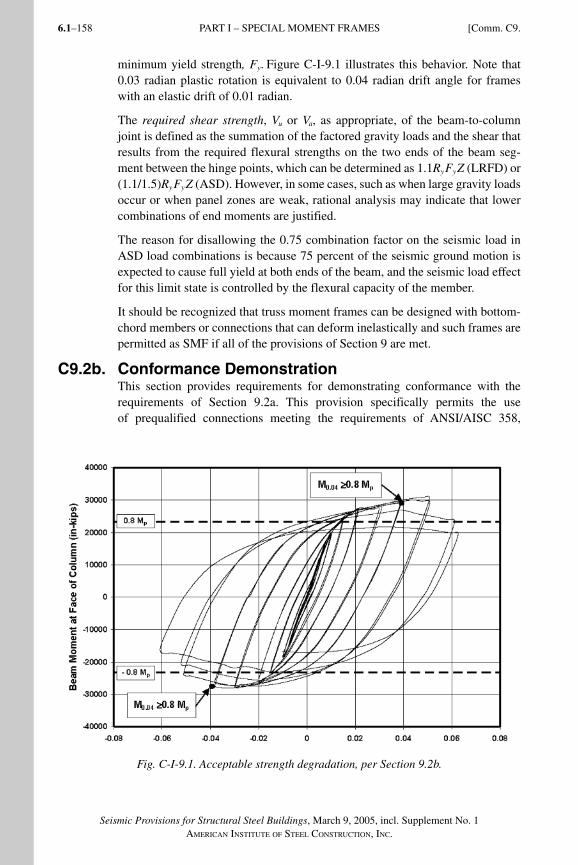
Seismic Provisions for Structural Steel Buildings, March 9, 2005, incl. Supplement No. 1AMERICAN INSTITUTE OF STEEL CONSTRUCTION, INC.
6.1–158
minimum yield strength, Fy. Figure C-I-9.1 illustrates this behavior. Note that 0.03 radian plastic rotation is equivalent to 0.04 radian drift angle for frames with an elastic drift of 0.01 radian.
The required shear strength, Vu or Va, as appropriate, of the beam-to-column joint is defined as the summation of the factored gravity loads and the shear that results from the requ ired flexural strengths on the two ends of the beam seg-ment between the hinge points, which can be determined as 1.1RyFyZ (LRFD) or (1.1/1.5)RyFyZ (ASD). However, in some cases, such as when large gravity loads occur or when panel zones are weak, rational analysis may indicate that lower combinations of end moments are justified.
The reason for disallowing the 0.75 combination factor on the seismic load in ASD load combinations is because 75 percent of the seismic ground motion is expected to cause full yield at both ends of the beam, and the seismic load effect for this limit state is controlled by the flexural capacity of the member.
It should be recognized that truss moment frames can be designed with bottom-chord members or connections that can deform inelastically and such frames are permitted as SMF if all of the provisions of Section 9 are met.
C9.2b. Conformance DemonstrationThis section provides requirements for demonstrating conformance with the requirements of Section 9.2a. This provision specifically permits the use of prequalified connections meeting the requirements of ANSI/AISC 358,
Fig. C-I-9.1. Acceptable strength degradation, per Section 9.2b.
PART I – SPECIAL MOMENT FRAMES [Comm. C9.
SeismicProvComm1.indd 158SeismicProvComm1.indd 158 9/8/06 3:13:17 PM9/8/06 3:13:17 PMProcess BlackProcess Black
6.1–159
Seismic Provisions for Structural Steel Buildings, March 9, 2005, incl. Supplement No. 1AMERICAN INSTITUTE OF STEEL CONSTRUCTION, INC.
Prequalified Connections for Special and Intermediate Steel Moment Frames for Seismic Applications (AISC, 2005a) to facilitate and standardize connection design. Other prequalification panels may be acceptable but are subject to the approval of the authority having jurisdiction. Use of connections qualified by prior tests or project specific tests may also be used, although the engineer of record is responsible for substantiating the connection. Published testing, such as that conducted as part of the SAC project and reported in FEMA 350 and 355 or project-specific testing may be used to satisfy this provision.
C9.3. Panel Zone of Beam-to-Column Connections (beam web parallel to column web)Cyclic testing has demonstrated that significant ductility can be obtained through shear yielding in column panel zones through many cycles of inelastic distortion (Popov, Blondet, Stepanov and Stojadinovic, 1996; Slutter, 1981; Becker, 1971; Fielding and Huang, 1971; Krawinkler, 1978). Consequently, it is not generally necessary to provide a panel zone that is capable of developing the full flexural strength of the connected beams if the available strength of the panel zone can be predicted. However, the usual assumption that the Von Mises criterion applies and the shear strength is 0.55Fydct does not match the actual behavior observed in many tests into the inelastic range. Due to the presence of the column flanges, strain hardening and other phenomena, panel zone shear strengths in excess of Fydct have been observed. Accordingly, Equation J10-11 of the Specifica-tion accounts for the significant strength contribution of thick column flanges.
Despite the ductility demonstrated by properly proportioned panel zones in pre-vious studies, excessive panel zone distortions can adversely affect the perfor-mance of beam-to-column connections (Englekirk, 1999; El-Tawil, Mikesell, Vidarsson and Kunnath, 1999). Consequently, the provisions require that the panel zone design match that of the successfully tested connections used to qual-ify the connection being used. The balance of the procedure of Section 9.3a is intended to provide a minimum strength level to prevent excessively weak panel zones, which may lead to unacceptable column distortion. Where prequalified connections described in FEMA 350 (FEMA, 2000a) are used, the design of panel zones according to the methods given therein, generally meet the require-ments in Section 9.3a. This should be verified by the designer.
The equations in Section J10.6 of the Specification represent the available strength in the inelastic range and, therefore, are for comparison to limiting strengths of connected members. In Section 9.3a of the Provisions, φv has been set equal to unity and Ωv set equal to 1.50, to allow a direct comparison between available strength of the beam and the column panel zone. In the Specification, the engineer is given the option to consider inelastic deformations of the panel zone in the analysis. Separate sets of equations are provided for use when these
deformations are and are not considered. In the 2002 Seismic Provisions, only one equation was provided (Equation 9-1, which is the same as Equation J10-11
Comm. C9.] PART I – SPECIAL MOMENT FRAMES
SeismicProvComm1.indd 159SeismicProvComm1.indd 159 9/8/06 3:13:18 PM9/8/06 3:13:18 PMProcess BlackProcess Black
Seismic Provisions for Structural Steel Buildings, March 9, 2005, incl. Supplement No. 1AMERICAN INSTITUTE OF STEEL CONSTRUCTION, INC.
6.1–160
of the Specification) and consideration of the inelastic deformation of the panel zone in the analysis was required.
It should be noted that the equations used in the Provisions differ somewhat from the recommendations of FEMA 350 and are slightly less conservative for some situations. However, as noted above, the equations of FEMA 350 are used for design with the connections prequalified therein, and those in the Provisions are used only to provide a check for minimum thickness, with the actual panel zone thicknesses normally being determined by comparison to tested connections.
The application of the moments at the column face to determine the required shear strength of the panel zone recognizes that beam hinging will take place at a location away from the beam-to-column connection, which will result in amplified effects on the panel zone shear. The previous version of this provision included a reduction factor of 0.8 on the beam yielding effects, which was in-tended to recognize that, in some cases, gravity loads might inhibit the develop-ment of plastic hinges on both sides of a column. However, there is no assurance that this will be the case, especially for one-sided connections and at perimeter frames where gravity loads may be relatively small (El-Tawil and others, 1999; El-Tawil, 2000).
This provision requires that the panel zone thickness be determined using the same method as the one used to determine the panel zone thickness in the tested connection, with a minimum value as described in the remainder of the section. The intent is that the local deformation demands on the various elements in the structure be consistent with the results of the tests that justify the use of the con-nection. The expected shear strength of the panel zone in relation to the maxi-mum expected demands that can be developed by the beam(s) framing into the column should be consistent with the relative strengths that existed in the tested connection configuration. Many of the connection tests were performed with a one-sided configuration. If the structure has a two-sided connection configura-tion with the same beam and column sizes as a one-sided connection test, the panel zone shear demand will be about twice that of the test. Therefore, in order to obtain the same relative strength, the panel zone thickness to be provided in the structure should be approximately twice that of the test.
To minimize shear buckling of the panel zone during inelastic deformations, the minimum panel zone thickness is set at one-ninetieth (190) of the sum of its depth and width. Thus, when the column web and web doubler plate(s) each meet the requirements of Equation 9-2, their interconnection with plug welds is not required. Otherwise, the column web and web doubler plate(s) can be intercon-nected with plug welds as illustrated in Figure C-I-9.2 and the total panel zone thickness can be used in Equation 9-2.
Section 9.3b provides no specific guidance on the number or location of plug welds needed to prevent buckling of the doubler plate. As a minimum, it is clear that the spacing should divide the plate into rectangular panels in such a way that
PART I – SPECIAL MOMENT FRAMES [Comm. C9.
SeismicProvComm1.indd 160SeismicProvComm1.indd 160 9/8/06 3:13:18 PM9/8/06 3:13:18 PMProcess BlackProcess Black
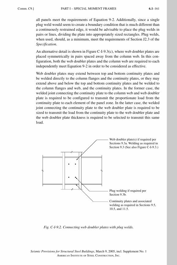
6.1–161
Seismic Provisions for Structural Steel Buildings, March 9, 2005, incl. Supplement No. 1AMERICAN INSTITUTE OF STEEL CONSTRUCTION, INC.
all panels meet the requirements of Equation 9-2. Additionally, since a single plug weld would seem to create a boundary condition that is much different than a continuously restrained edge, it would be advisable to place the plug welds in pairs or lines, dividing the plate into appropriately sized rectangles. Plug welds, when used, should, as a minimum, meet the requirements of Section J2.3 of the Specification.
An alternative detail is shown in Figure C-I-9.3(c), where web doubler plates are placed symmetrically in pairs spaced away from the column web. In this con-figuration, both the web doubler plates and the column web are required to each independently meet Equation 9-2 in order to be considered as effective.
Web doubler plates may extend between top and bottom continuity plates and be welded directly to the column flanges and the continuity plates, or they may extend above and below the top and bottom continuity plates and be welded to the column flanges and web, and the continuity plates. In the former case, the welded joint connecting the continuity plate to the column web and web doubler plate is required to be configured to transmit the proportionate load from the continuity plate to each element of the panel zone. In the latter case, the welded joint connecting the continuity plate to the web doubler plate is required to be sized to transmit the load from the continuity plate to the web doubler plate and the web doubler plate thickness is required to be selected to transmit this same load.
Fig. C-I-9.2. Connecting web doubler plates with plug welds.
Comm. C9.] PART I – SPECIAL MOMENT FRAMES
Web doubler plate(s) if required per Sections 9.3a. Welding as required in Section 9.3 (See also Figure C-I-9.3.)
Plug welding if required per Section 9.3b.
Continuity plates and associated welding as required in Sections 9.5, 10.5, and 11.5.
SeismicProvComm1.indd 161SeismicProvComm1.indd 161 9/8/06 3:13:18 PM9/8/06 3:13:18 PMProcess BlackProcess Black
Seismic Provisions for Structural Steel Buildings, March 9, 2005, incl. Supplement No. 1AMERICAN INSTITUTE OF STEEL CONSTRUCTION, INC.
6.1–162
Shear loads transmitted to the web doubler plates from the continuity plates are equilibrated by shear loads along column-flange edges of the web doubler plate. It is anticipated that the panel zone will yield in a seismic event, and the welds connecting the web doubler plate to the column flanges are required to be sized to develop the shear strength of the full web doubler plate thickness. Either a complete-joint-penetration groove-welded joint or a fillet-welded joint can be used as illustrated in Figure C-I-9.3. The plate thickness and column fillet radius should be considered before selecting the fillet-welded joint.
The use of diagonal stiffeners for strengthening and stiffening of the panel zone has not been adequately tested for low-cycle reversed loading into the inelastic range. Thus, no specific recommendations are made at this time for special seis-mic requirements for this detail.
C9.4. Beam and Column LimitationsReliable inelastic deformation requires that width-thickness ratios of projecting elements be limited to a range that provides a cross section resistant to local buckling into the inelastic range. Although the width-thickness ratios for com-pact elements in Specification Table B4.1 are sufficient to prevent local buckling before the onset of yielding, the available test data suggest that these limits are not adequate for the required inelastic performance in SMF. The limits given in Table I-8-1 are deemed adequate for ductilities to 6 or 7 (Sawyer, 1961; Lay, 1965; Kemp, 1986; Bansal, 1971)
C9.5. Continuity PlatesWhen subjected to seismic loads, an interior column (in other words, one with adjacent moment connections to both flanges) in a moment frame receives a tensile flange force on one flange and a compressive flange force on the opposite side. When stiffeners are required, it is normal to place a full-depth transverse stiffener on each side of the column web. As this stiffener provides a load path for the flanges on both sides of the column, it is commonly called a continuity plate. The stiffener also serves as a boundary to the very highly stressed panel zone. When the formation of a plastic hinge is anticipated adjacent to the column, the required strength is the flange force exerted when the full beam plastic moment has been reached, including the effects of overstrength and strain hardening, as well as shear amplification from the hinge location to the column face.
Post-Northridge studies have shown that even when continuity plates of sub-stantial thickness are used, inelastic strains across the weld of the beam flange to the column flange are substantially higher opposite the column web than they are at the flange tips. Some studies have indicated stress concentrations higher than 4, which can cause the weld stress at the center of the flange to exceed its tensile strength before the flange force exceeds its yield strength based on a uniform average stress. This condition may be exacerbated if relatively thin continuity plates are used or if continuity plates are omitted entirely. For this reason, an earlier formula that permitted elimination of continuity plates where column flanges were very thick was rescinded in FEMA 267 (FEMA, 1995) and the Supplement to FEMA 267 (FEMA, 1997b). The use of continuity plates
PART I – SPECIAL MOMENT FRAMES [Comm. C9.
SeismicProvComm1.indd 162SeismicProvComm1.indd 162 9/8/06 3:13:18 PM9/8/06 3:13:18 PMProcess BlackProcess Black
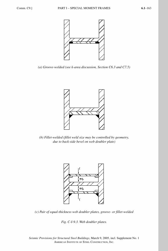
6.1–163
Seismic Provisions for Structural Steel Buildings, March 9, 2005, incl. Supplement No. 1AMERICAN INSTITUTE OF STEEL CONSTRUCTION, INC.
Comm. C9.] PART I – SPECIAL MOMENT FRAMES
(a) Groove-welded (see k-area discussion, Section C6.3 and C7.5)
(b) Fillet-welded (fillet weld size may be controlled by geometry, due to back-side bevel on web doubler plate)
(c) Pair of equal-thickness web doubler plates, groove- or fillet-welded
Fig. C-I-9.3. Web doubler plates.
SeismicProvComm1.indd 163SeismicProvComm1.indd 163 9/8/06 3:13:19 PM9/8/06 3:13:19 PMProcess BlackProcess Black
Seismic Provisions for Structural Steel Buildings, March 9, 2005, incl. Supplement No. 1AMERICAN INSTITUTE OF STEEL CONSTRUCTION, INC.
6.1–164
was recommended in all cases unless tests showed that other design features of a given connection are so effective in reducing or redistributing flange stresses that the connection will work without them. Later studies, discussed in FEMA 355D (FEMA, 2000e), have indicated that the old formulas and approaches may not have been wrong, as described below. However, pending further study, all features of SMRF connections are required to be based on either prequalification or qualification testing.
The FEMA-sponsored SAC steel project studied the issue of continuity plates in depth. According to FEMA 350 (FEMA, 2000a), continuity plates are not required when:
t b tF R
F Rcf f f
yb yb
yc yc
> 0 40 1 8. . (C9-3)
and
tcf > bf /6 (C9-4)
Equation C9-3 is similar to the equation in older codes, except for the R y factors. Justification for the use of Equation C9-3 and C9-4 is based on studies by Ricles discussed in FEMA 355D (FEMA, 2000e).
The intent of the procedures of FEMA 350 was that use of the preceding formu-las was adequate for the determination of the need for continuity plates for the prequalified connections therein.
According to FEMA 350, the thickness of continuity plates is to be determined according to the following:
• For one-sided (exterior) connections, continuity plate thickness should be at least one-half of the thickness of the beam flanges.
• For two-sided (interior) connections, the continuity plates should be equal in thickness to the thicker of the two beam flanges on either side of the column.
• The plates should also conform to Section J10.8 of the Specification.
C9.6. Column-Beam Moment RatioThe strong-column weak-beam (SC/WB) concept is perhaps one of the least understood seismic provisions in steel design. It is often mistakenly assumed that it is formulated to prevent any column flange yielding in a frame and that if such yielding occurs, the column will fail. Tests have shown that yielding of col-umns in moment frame subassemblages does not necessarily reduce the lateral strength at the expected seismic displacement levels.
The SC/WB concept represents more of a global frame concern than a concern at the interconnections of individual beams and columns. Schneider, Roeder and Carpenter (1991) and Roeder (1987) showed that the real benefit of meeting
PART I – SPECIAL MOMENT FRAMES [Comm. C9.
SeismicProvComm1.indd 164SeismicProvComm1.indd 164 9/8/06 3:13:19 PM9/8/06 3:13:19 PMProcess BlackProcess Black
6.1–165
Seismic Provisions for Structural Steel Buildings, March 9, 2005, incl. Supplement No. 1AMERICAN INSTITUTE OF STEEL CONSTRUCTION, INC.
Comm. C9.] PART I – SPECIAL MOMENT FRAMES
SC/WB requirements is that the columns are generally strong enough to force flexural yielding in beams in multiple levels of the frame, thereby achieving a higher level of energy dissipation. Weak column frames, particularly those with weak or soft stories, are likely to exhibit an undesirable response at those stories with the highest column demand-to-capacity ratios.
It should be noted that compliance with the SC/WB concept and Equation 9-3 gives no assurance that individual columns will not yield, even when all connec-tion locations in the frame comply. It can be shown by nonlinear analysis that, as the frame deforms inelastically, points of inflection shift and the distribution of moments varies from the idealized condition. Nonetheless, yielding of the beams rather than the columns will predominate and the desired inelastic perfor-mance will be achieved in frames with members sized to meet the requirement in Equation 9-3.
Previous formulations of this relationship idealized the beam/column intersec-tion as a point at the intersection of the member centerlines. Post-Northridge beam-to-column moment connections are generally configured to shift the plas-tic hinge location into the beam away from the column face and a more gen-eral formulation was needed. FEMA 350 provides recommendations regarding the assumed location of plastic hinges for different connection configurations or they can be determined from the applicable qualifying tests. Recognition of expected beam strength (see Commentary Section C6.2) is also incorporated into Equation 9-3.
Three exceptions to Equation 9-3 are given. In the first exception, columns with low axial loads used in one-story buildings or in the top story of a multi-story building need not meet Equation 9-3 because concerns for inelastic soft or weak stories are not significant in such cases. Additionally, exception is made for a limited percentage of columns with axial loads that are considered to be low enough to limit undesirable performance while still providing reasonable flex-ibility where the requirement in Equation 9-3 would be impractical, such as at large transfer girders. Finally, Section 9.6 provides an exception for columns in levels that are significantly stronger than in the level above because column yielding at the stronger level would be unlikely.
C9.7. Lateral Bracing at Beam-to-Column ConnectionsColumns are required to be braced to prevent rotation out of the plane of the moment frame, particularly if inelastic behavior is expected in or adjacent to the beam-to-column connection during high seismic activity.
C9.7a. Braced Connections Beam-to-column connections are usually braced laterally by the floor or roof framing. When this is the case and it can be shown that the column remains elastic outside of the panel zone, lateral bracing of the column flanges is required only at the level of the top flanges of the beams. If it cannot be shown that the column remains elastic, lateral bracing is required at both the top and bottom
SeismicProvComm1.indd 165SeismicProvComm1.indd 165 9/8/06 3:13:19 PM9/8/06 3:13:19 PMProcess BlackProcess Black
Seismic Provisions for Structural Steel Buildings, March 9, 2005, incl. Supplement No. 1AMERICAN INSTITUTE OF STEEL CONSTRUCTION, INC.
6.1–166
beam flanges because of the potential for flexural yielding, and consequent lateral-torsional buckling of the column.
The required strength for lateral bracing at the beam-to-column connection is 2 percent of the nominal strength of the beam flange. In addition, the element(s) providing lateral bracing are required to have adequate stiffness to inhibit lat-eral movement of the column flanges (Bansal, 1971). In some cases, a bracing member will be required for such lateral bracing. Alternatively, calculations may show that adequate lateral bracing can be provided by the column web and con-tinuity plates or by the flanges of perpendicular beams.
The 1997 Seismic Provisions required column lateral bracing when the ratio in Equation 9-3 was less than 1.25. The intent of this provision was to require bracing to prevent lateral-torsional buckling for cases where it cannot be as-sured that the column will not hinge. Studies utilizing inelastic analyses (Gupta and Krawinkler, 1999; Bondy, 1996) have shown that, in severe earthquakes, plastic hinging can occur in the columns even when this ratio is significantly larger than 1.25. The revised limit of 2.0 was selected as a reasonable cut-off because column plastic hinging for values greater than 2.0 only occurs in the case of extremely large story drifts. The intent of the revisions to this section is to encourage appropriate bracing of column flanges rather than to force the use of much heavier columns.
C9.7b. Unbraced ConnectionsUnbraced connections occur in special cases, such as in two-story frames, at mechanical floors or in atriums and similar architectural spaces. When such con-nections occur, the potential for out-of-plane buckling at the connection should be minimized. Three provisions are given for the columns to limit the likelihood of column buckling.
C9.8. Lateral Bracing of Beams Spacing of lateral braces for beams in SMF systems is specified not to exceed 0.086ryE/Fy. This limitation, which is unchanged from previous editions, was originally based on an examination of lateral bracing requirements from early work on plastic design and based on limited experimental data on beams subject to cyclic loading. Lateral bracing requirements for SMF beams have since been investigated in greater detail in Nakashima, Kanao and Liu (2002). This study indicates that a beam lateral support spacing of 0.086ryE/Fy is appropriate, and slightly conservative, to achieve an interstory drift angle of 0.04 radian.
For calculating bracing strength according to Equation A-6-7 of the Specifica-tion, the use of Cd = 1 is justified because the AISC equations have an implicit assumption that the beams will be subjected to top flange loading. One can see this by comparing the 1999 LRFD Specification for Structural Steel Buildings (AISC, 2000a) Equation C3-9 to the 1999 Commentary Equation C-C3-4b, where the Specification equation is based on a conservative assumption of Ct = 2. In the case of seismic frames, where the moments are introduced via the
PART I – SPECIAL MOMENT FRAMES [Comm. C9.
SeismicProvComm1.indd 166SeismicProvComm1.indd 166 9/8/06 3:13:20 PM9/8/06 3:13:20 PMProcess BlackProcess Black
6.1–167
Seismic Provisions for Structural Steel Buildings, March 9, 2005, incl. Supplement No. 1AMERICAN INSTITUTE OF STEEL CONSTRUCTION, INC.
Comm. C9.] PART I – SPECIAL MOMENT FRAMES
beam-column connections, Ct = 1. Strictly speaking, the correct solution would be to use the commentary equation with Ct = 1 and Cd =1 at all locations except for braces at the inflection point where Cd = 2. As the Provisions now read, we are essentially implying that the product of Ct(Cd) = 2.0 by the implied value of Ct = 2 and Cd = 1.
In addition to bracing along the beam length, the provisions of this section call for the placement of lateral bracing to be near the location of expected plas-tic hinges. Such guidance dates to the original development of plastic design procedures in the early 1960s. In moment frame structures, many connection details attempt to move the plastic hinge a short distance away from the beam-to-column connection. Testing carried out as part of the SAC program (FEMA, 2000a) indicated that the bracing provided by typical composite floor slabs is adequate to avoid excessive strength deterioration up to the required interstory drift angle of 0.04 radian. As such, the FEMA recommendations do not require the placement of supplemental lateral bracing at plastic hinge locations adja-cent to column connections for beams with composite floor construction. These provisions allow the placement of lateral braces to be consistent with the tested connections that are used to justify the design. For conditions where drifts larger than the anticipated 0.04 radians are anticipated or improved performance is desired, the designer may decide to provide additional lateral bracing near these plastic hinges. If lateral braces are provided, they should provide an available strength of 6 percent of the expected capacity of the beam flange at the plastic hinge location. If a reduced beam section connection detail is used, the reduced flange width may be considered in calculation of the bracing force. Placement of bracing connections should consider the requirements of Section 9.2d.
C9.9 Column SplicesIn the 1997 Seismic Provisions, there were no special requirements for column splices in SMF systems other than those in Section 8.3. Section 8.3 was intended to take care of column bending at the splice by requiring splices to be at least 4 ft (1.2 m) or one-half the column clear height from the beam-to-column con-nection. This requirement was based on the general recognition that in elastic analyses of moment frames the columns are typically bent in double curvature with an inflection point somewhere near the middle of the column height, and therefore, little bending of the column was expected at the splice.
Nonlinear analyses performed during the FEMA/SAC project following the Northridge Earthquake, clearly demonstrated that bending moments in the mid-height of columns can be substantial and that, in fact, the columns may be bent in single curvature under some conditions. Given this fact, and the recognition of the potential for severe damage or even collapse due to failure of column splices, the need for special provisions for splices of moment frame columns was apparent.
The provisions of Section 9.9 are intended to assure that the expected flex-ural strength of the smaller column is fully developed, either through use of complete-joint-penetration groove welds or another connection that provides
SeismicProvComm1.indd 167SeismicProvComm1.indd 167 9/8/06 3:13:20 PM9/8/06 3:13:20 PMProcess BlackProcess Black
Seismic Provisions for Structural Steel Buildings, March 9, 2005, incl. Supplement No. 1AMERICAN INSTITUTE OF STEEL CONSTRUCTION, INC.
6.1–168
similar strength, and that the shear strength of the splice is sufficient to resist the shear developed when Mpc occurs at each end of the spliced column.
The exception permits the design of splices based on appropriate inelastic analy-sis to determine required strength, coupled with the use of principles of fracture mechanics to determine the available strength of the connection.
C10. INTERMEDIATE MOMENT FRAMES (IMF)The intermediate moment frames (IMF) and ordinary moment frames (OMF) are considered to be lower ductility systems as compared to special moment frames. Consequently, building codes assign lower response modification and deflec-tion amplification factors to these systems. Both systems are intended primarily for use in buildings classified in lower seismic design categories and heights (FEMA, 2003). Sections C10.1, Scope, and C11.1, Scope, summarize typical seismic design categories and height applications anticipated by these Provi-sions, though the decision to use these systems on any specific building should be made considering the applicable building code and performance expectations for that building.
The IMF is based on a tested connection design with a qualifying interstory drift angle of 0.02 radian, which is half that required for the SMF. The OMF is based on a prescriptive design procedure with no specific rotation angle requirements, but it may be assumed that these connections should be capable of withstanding an interstory drift angle of up to about 0.01 radians and should remain mostly elastic. It is assumed that these limited connection rotations will be achieved by use of larger frame members owing to the lower R and Cd values used in design. However, these lower values may not reliably ensure that the resulting frames will not experience excessive rotation unless reduced drift limits are used. The designer may wish to consider this issue in the design.
Commentary Section C9 for special moment frames offers additional commen-tary relevant to IMF and OMF connections.
The statement, “No additional requirements beyond the Specification.” which appears in Sections 10.3, 10.6, 10.7, 11.3, 11.4, and 11.7 indicates that the Pro-visions require no limitations or provisions beyond what is in the Specification (AISC, 2005) on that particular topic.
C10.1. ScopeThe intermediate moment frame (IMF) currently specified is essentially the same as the ordinary moment frame (OMF) system defined in the 1997 Seismic Provi-sions. This new IMF is intended to provide limited levels of inelastic rotation ca-pability and is based on tested designs. Due to the limited rotational capacity of IMF as compared to SMF, SEI/ASCE 7 (ASCE, 2002) places significant height and other limitations on their use.
PART I – SPECIAL MOMENT FRAMES [Comm. C9.
SeismicProvComm1.indd 168SeismicProvComm1.indd 168 9/8/06 3:13:20 PM9/8/06 3:13:20 PMProcess BlackProcess Black
6.1–169
Seismic Provisions for Structural Steel Buildings, March 9, 2005, incl. Supplement No. 1AMERICAN INSTITUTE OF STEEL CONSTRUCTION, INC.
Comm. C10.] PART I – INTERMEDIATE MOMENT FRAMES
C10.2. Beam-to-Column ConnectionsThe minimum interstory drift angle required for IMF connections is 0.02 radian while that for SMF connections is 0.04 radian. This level of interstory drift angle has been established for this type of frame based on engineering judgment applied to available tests and analytical studies, primarily those included in FEMA (2000d) and FEMA (2000f).
One connection commonly used in the IMF, which has welded unreinforced flanges and a bolted web, is the fully restrained seismic moment connection referred to as WUF-B (welded unreinforced flange-bolted web).
The WUF-B connection is defined in FEMA 350, Section 3.5.1 (FEMA, 2000a), which specifies all the details for flange welding, weld access holes and for the bolted shear tab for connection to the beam web. It is very similar to the WUF-W (welded unreinforced flange-welded web) connection specified in FEMA 350, Section 3.5.2, except that the beam web is bolted (not welded) to the shear tab.
For design of the bolts to the beam web, slip-critical high strength bolts are uti-lized. However, the capacity of the high strength bolts is based on bearing bolt capacity using a resistance factor of 1.0. These high strength bolts are sized to resist the maximum shear that is developed in the beam when yielding occurs at both ends of the beam under seismic loads plus any tributary gravity loads.
Based upon FEMA 350, the WUF-B connection did not perform as well as the WUF-W connection, and it was not always capable of sustaining interstory drift angles as large as 0.04 radian. This was sometimes due to transferring some shear load from the beam web to the beam flanges caused by slight slippage of the bolts to the shear plate.
Because of the above, FEMA 350 prequalified this WUF-B connection only for ordinary moment frames and not special moment frames. Based on recent revi-sions of types of seismic moment connections as defined by these Provisions (see C10.1), this connection would now meet the requirements and be prequali-fied for intermediate moment frames, but not for special moment frames.
C10.2b. Conformance DemonstrationConformance demonstration of IMF connections is the same as for SMF con-nections, except that the required interstory drift angle is smaller. Refer to Com-mentary Section C9.2b.
C10.2d. Protected ZoneThe requirements in this section are identical to those in Section 9.2d.
C10.4. Beam and Column Limitations
C10.4a. Width-Thickness LimitationsBecause the rotational demands on IMF beams and columns are expected to be lower than for SMF, the width-thickness limitations for IMF refer to Table B4.1 of the Specification. See Section C9.4 for further discussion.
SeismicProvComm1.indd 169SeismicProvComm1.indd 169 9/8/06 3:13:20 PM9/8/06 3:13:20 PMProcess BlackProcess Black
Seismic Provisions for Structural Steel Buildings, March 9, 2005, incl. Supplement No. 1AMERICAN INSTITUTE OF STEEL CONSTRUCTION, INC.
6.1–170
C10.4b. Beam FlangesThe requirements in this section are identical to those in Section 9.4b.
C10.5. Continuity PlatesThe requirements in this section are identical to those in Section 9.5. See Section C9.5 for further discussion.
C10.8. Lateral Bracing of BeamsThe requirement for spacing of lateral bracing in this section is less severe than that in Section 9.8 because of the lower required drift angle for IMF as compared to SMF. In this case, the required spacing of bracing is roughly double that for SMF. See Section C9.8 for further discussion on lateral bracing of beams.
C11. ORDINARY MOMENT FRAMES (OMF)
C11.1. ScopeThe ordinary moment frame (OMF) is intended to provide for a limited level of inelastic rotation capability that is less than that of the IMF. Unlike the IMF, the OMF is based on a prescriptive design procedure. The prescriptive requirements of this section are based on lessons learned from the Northridge Earthquake steel moment frame investigations and the results of analytical research and physical testing completed as part of the FEMA SAC project. The OMF connection incorporates certain prescriptive details found to be beneficial to connection per-formance. See Commentary Section C10 for additional commentary on OMF.
Due to the limited rotational capacity of OMF as compared to SMF, SEI/ASCE 7 (ASCE, 2002) places significant height and other limitations on their use.
OMF Knee-Brace Systems. Knee-brace systems use an axial brace from the beam to the column to form a moment connection. Resistance to lateral loads is by flexure of the beam and column. In the absence of configurations qualified by cyclic testing, knee-brace moment frames may be designed as ordinary moment frames.
The system can be considered as analogous to a moment frame with haunch type connections. The brace represents the sloping bottom flange and the beam rep-resents the web and top flange of the haunch. The knee brace carries axial loads only, while the beam-to-column connection carries both axial load and shear.
The design method would be to connect the beam/girder end to the column and the brace ends based on the forces required to develop 1.1RyMp of the beam/girder at the location of the brace to beam work point. The beam-to column-connection, knee-brace connections, and knee-brace member design shall be designed for the greater of the forces resulting from this approach or the forces determined with the load combinations per the applicable building code using the amplified seismic load. The column and beams shall be braced either directly or indirectly at the brace locations for a lateral force equal to a minimum of 2 percent of the brace axial design force.
PART I – INTERMEDIATE MOMENT FRAMES [Comm. C10.
SeismicProvComm1.indd 170SeismicProvComm1.indd 170 9/8/06 3:13:20 PM9/8/06 3:13:20 PMProcess BlackProcess Black
6.1–171
Seismic Provisions for Structural Steel Buildings, March 9, 2005, incl. Supplement No. 1AMERICAN INSTITUTE OF STEEL CONSTRUCTION, INC.
This system is not anticipated to be as susceptible to column failures as a K-type braced frame since the column is designed for the moments resulting from forces from the knee brace(s). For columns with knee bracing on opposite sides, consideration should be given to column strength if the knee brace on one side were to fail.
Although not required per Section 11, some methods that would be expected to improve performance of knee-brace frames include designing beams to span between columns under full gravity loads without benefit of the knee braces, design of strong column/weak beam frames, the use of compact shapes for all frame members, and the design of braces for 125 percent of forces per the above design method.
C11.2. Beam-to-Column ConnectionsEven though the inelastic rotation demands on OMF are expected to be low, the Northridge Earthquake damage demonstrated that little, if any, inelastic rota-tional capacity was available in the connection prescribed by the codes prior to 1994. Thus, even for OMF, new connection requirements are needed, and these are provided in this section.
C11.2a. Requirements: FR Moment ConnectionsThe requirements given for OMF connection design in this section are prescrip-tive, to allow the engineer to design the connections, where OMF are permitted, without testing or use of test data. The prescriptive designs are based on strength calculations and prescriptive details.
For FR moment connections, the required flexural strength is given as the lesser of 1.1RyMp (LRFD) or (1.1/1.5)RyMp (ASD) or the maximum moment that can be developed by the system. The 1.1 factor in the equation is to recognize the limited strain hardening expected, as well as other possible overstrength.
It is reasonable to limit the requirements to the maximum moment that can be developed by the system, because the size of the beam or girder may have been determined to meet demands greater than the seismic demands. Factors that may limit the maximum moment that can be developed in the beam include the following:
(1) The strength of the columns;
(2) The strength of the foundations to resist uplift;
(3) The limiting earthquake force determined using R = 1.
In addition to the strength requirement, detailing enhancements are required that have been demonstrated by FEMA 350 (FEMA, 2000a) to significantly improve the connection performance as compared to past steel moment frame construction.
The testing completed by the SAC Joint Venture found that improved perfor-mance into the inelastic range can be obtained with the following improvements over the prescriptive pre-Northridge connection detail: (1) the use of notch-tough weld metal; (2) the removal of backing bars, backgouging of the weld root, and
Comm. C11.] PART I – ORDINARY MOMENT FRAMES
SeismicProvComm1.indd 171SeismicProvComm1.indd 171 9/8/06 3:13:21 PM9/8/06 3:13:21 PMProcess BlackProcess Black
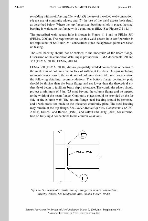
Seismic Provisions for Structural Steel Buildings, March 9, 2005, incl. Supplement No. 1AMERICAN INSTITUTE OF STEEL CONSTRUCTION, INC.
6.1–172
rewelding with a reinforcing fillet weld; (3) the use of a welded web connection; (4) the use of continuity plates; and (5) the use of the weld access hole detail as described below. Where the top flange steel backing is left in place, the steel backing is welded to the flange with a continuous fillet. (See Figure C-I-11.1.)
The prescribed weld access hole is shown in Figure 11-1 and in FEMA 350 (FEMA, 2000a). The requirement to use this weld access hole configuration is not stipulated for SMF nor IMF connections since the approved joints are based on testing.
The steel backing should not be welded to the underside of the beam flange. Discussion of the connection detailing is provided in FEMA documents 350 and 353 (FEMA, 2000a; FEMA, 2000b).
FEMA 350 (FEMA, 2000a) did not prequalify welded connections of beams to the weak axis of columns due to lack of sufficient test data. Designs including moment connections to the weak axis of columns should take into consideration the following detailing recommendations. The bottom flange continuity plate should be thicker than the beam flange and set lower than the theoretical un-derside of beam to facilitate beam depth tolerance. The continuity plates should project a minimum of 3 in. (75 mm) beyond the column flange and be tapered to the width of the beam flange. Continuity plates should be provided on the far side of the column web. The bottom flange steel backing should be removed, and a weld transition made to the thickened continuity plate. The steel backing may remain at the top flange. See LRFD Manual of Steel Construction (AISC, 2001a), Driscoll and Beedle, (1982), and Gilton and Uang (2002) for informa-tion on fully rigid connections to the column weak axis.
Fig. C-I-11.1 Schematic illustration of strong-axis moment connection: directly welded. See Kaufmann, Xue, Lu and Fisher (1996).
PART I – ORDINARY MOMENT FRAMES [Comm. C11.
SeismicProvComm1.indd 172SeismicProvComm1.indd 172 9/8/06 3:13:21 PM9/8/06 3:13:21 PMProcess BlackProcess Black
6.1–173
Seismic Provisions for Structural Steel Buildings, March 9, 2005, incl. Supplement No. 1AMERICAN INSTITUTE OF STEEL CONSTRUCTION, INC.
A welded beam-to-column moment connection in a strong-axis configuration similar to one tested at Lehigh University for the SAC Project is illustrated in Figure C-I-11.1. FEMA 350 (FEMA, 2000a) recommends this detail for use in OMF with similar member sizes and other conditions.
Cyclic testing has shown that use of weld access holes can cause premature fracture of the beam flange at end-plate moment connections (Meng and Murray, 1997). Short to long weld access holes were investigated with similar results. Therefore, weld access holes are not permitted for end-plate moment connections.
For information on bolted moment end-plate connections in seismic applications, refer to Murray and Shoemaker (2002) and FEMA 355D (FEMA, 2000e).
C11.2b. Requirements: PR Moment ConnectionsSection 11.2b gives strength requirements for PR Connections, but does not provide complete prescriptive design requirements. For design information on PR connections, the reader is referred to Leon (1990); Leon (1994); Leon and Ammerman (1990); Leon and Forcier (1992); Bjorhovde, Colson and Brozzet-ti(1990); Hsieh and Deierlein (1991); Leon, Hoffman and Staeger (1996); and FEMA 355D (FEMA, 2000e).
C11.5. Continuity PlatesThis section requires continuity plates for OMF connections when the thickness of the column flange to which the beam, or beam flange connection plate, is welded does not meet the requirements of the given formulas. The first of the formulas was given in the 1992 Seismic Provisions in a slightly different form.
Among the many requirements promulgated for moment frames immediately after the Northridge Earthquake of 1994 was a requirement that continuity plates be provided in all moment frame connections that employ welded flanges or welded flange plates. Finite element analyses conducted by El-Tawil and Kun-nath, and experimental studies by Ricles, conducted as part of the FEMA/SAC
program (see FEMA 355D), showed that when the column flange met the condi-tions in the formulas, there was negligible difference in the beam flange stresses at the connection whether or not continuity plates were provided.
The Provisions require that SMF and IMF use continuity plates to match those in the required tested connections. FEMA 350 recommends use of the same formu-las given in this section for SMF and IMF for use with the prequalified connec-tions included therein. In other words, continuity plates would not be required with the prequalified connections, even if the tests upon which they were based use them, if the conditions of the formulas were met.
The thicknesses of the continuity plates as required herein are consistent with the results of the FEMA/SAC studies cited above.
Comm. C11.] PART I – ORDINARY MOMENT FRAMES
SeismicProvComm1.indd 173SeismicProvComm1.indd 173 9/8/06 3:13:21 PM9/8/06 3:13:21 PMProcess BlackProcess Black
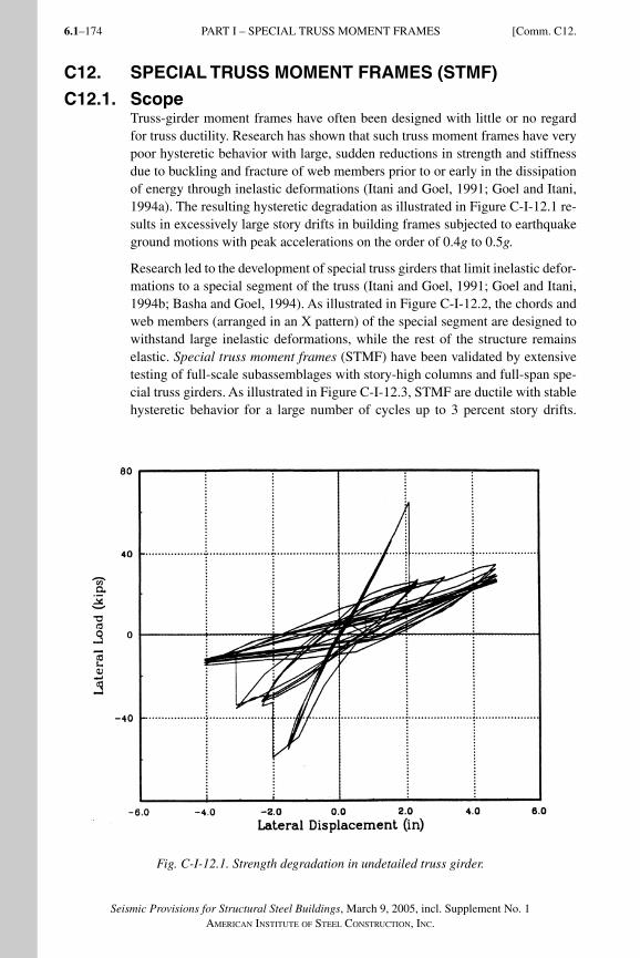
Seismic Provisions for Structural Steel Buildings, March 9, 2005, incl. Supplement No. 1AMERICAN INSTITUTE OF STEEL CONSTRUCTION, INC.
6.1–174
C12. SPECIAL TRUSS MOMENT FRAMES (STMF)
C12.1. ScopeTruss-girder moment frames have often been designed with little or no regard for truss ductility. Research has shown that such truss moment frames have very poor hysteretic behavior with large, sudden reductions in strength and stiffness due to buckling and fracture of web members prior to or early in the dissipation of energy through inelastic deformations (Itani and Goel, 1991; Goel and Itani, 1994a). The resulting hysteretic degradation as illustrated in Figure C-I-12.1 re-sults in excessively large story drifts in building frames subjected to earthquake ground motions with peak accelerations on the order of 0.4g to 0.5g.
Research led to the development of special truss girders that limit inelastic defor-mations to a special segment of the truss (Itani and Goel, 1991; Goel and Itani, 1994b; Basha and Goel, 1994). As illustrated in Figure C-I-12.2, the chords and web members (arranged in an X pattern) of the special segment are designed to withstand large inelastic deformations, while the rest of the structure remains elastic. Special truss moment frames (STMF) have been validated by extensive testing of full-scale subassemblages with story-high columns and full-span spe-cial truss girders. As illustrated in Figure C-I-12.3, STMF are ductile with stable hysteretic behavior for a large number of cycles up to 3 percent story drifts.
Fig. C-I-12.1. Strength degradation in undetailed truss girder.
PART I – SPECIAL TRUSS MOMENT FRAMES [Comm. C12.
SeismicProvComm1.indd 174SeismicProvComm1.indd 174 9/8/06 3:13:21 PM9/8/06 3:13:21 PMProcess BlackProcess Black
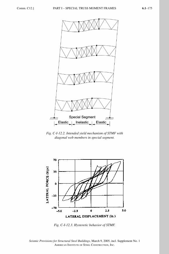
6.1–175
Seismic Provisions for Structural Steel Buildings, March 9, 2005, incl. Supplement No. 1AMERICAN INSTITUTE OF STEEL CONSTRUCTION, INC.
Fig. C-I-12.2. Intended yield mechanism of STMF with diagonal web members in special segment.
Fig. C-I-12.3. Hysteretic behavior of STMF.
Comm. C12.] PART I – SPECIAL TRUSS MOMENT FRAMES
SeismicProvComm1.indd 175SeismicProvComm1.indd 175 9/8/06 3:13:22 PM9/8/06 3:13:22 PMProcess BlackProcess Black
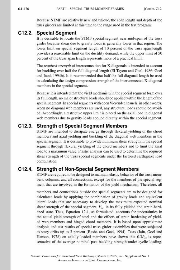
Seismic Provisions for Structural Steel Buildings, March 9, 2005, incl. Supplement No. 1AMERICAN INSTITUTE OF STEEL CONSTRUCTION, INC.
6.1–176
Because STMF are relatively new and unique, the span length and depth of the truss girders are limited at this time to the range used in the test program.
C12.2. Special SegmentIt is desirable to locate the STMF special segment near mid-span of the truss girder because shear due to gravity loads is generally lower in that region. The lower limit on special segment length of 10 percent of the truss span length provides a reasonable limit on the ductility demand, while the upper limit of 50 percent of the truss span length represents more of a practical limit.
The required strength of interconnection for X-diagonals is intended to account for buckling over half the full diagonal length (El-Tayem and Goel, 1986; Goel and Itani, 1994b). It is recommended that half the full diagonal length be used in calculating the design compression strength of the interconnected X-diagonal members in the special segment.
Because it is intended that the yield mechanism in the special segment form over its full length, no major structural loads should be applied within the length of the special segment. In special segments with open Vierendeel panels, in other words, when no diagonal web members are used, any structural loads should be avoid-ed. Accordingly, a restrictive upper limit is placed on the axial load in diagonal web members due to gravity loads applied directly within the special segment.
C12.3. Strength of Special Segment MembersSTMF are intended to dissipate energy through flexural yielding of the chord members and axial yielding and buckling of the diagonal web members in the special segment. It is desirable to provide minimum shear strength in the special segment through flexural yielding of the chord members and to limit the axial load to a maximum value. Plastic analysis can be used to determine the required shear strength of the truss special segments under the factored earthquake load combination.
C12.4. Strength of Non-Special Segment MembersSTMF are required to be designed to maintain elastic behavior of the truss mem-bers, columns, and all connections, except for the members of the special seg-ment that are involved in the formation of the yield mechanism. Therefore, all
members and connections outside the special segments are to be designed for calculated loads by applying the combination of gravity loads and equivalent lateral loads that are necessary to develop the maximum expected nominal shear strength of the special segment, Vne, in its fully yielded and strain-hard-ened state. Thus, Equation 12-1, as formulated, accounts for uncertainties in the actual yield strength of steel and the effects of strain hardening of yield-ed web members and hinged chord members. It is based upon approximate analysis and test results of special truss girder assemblies that were subjected to story drifts up to 3 percent (Basha and Goel, 1994). Tests (Jain, Goel and Hanson, 1978) on axially loaded members have shown that 0.3Pnc is repre-sentative of the average nominal post-buckling strength under cyclic loading.
PART I – SPECIAL TRUSS MOMENT FRAMES [Comm. C12.
SeismicProvComm1.indd 176SeismicProvComm1.indd 176 9/8/06 3:13:23 PM9/8/06 3:13:23 PMProcess BlackProcess Black
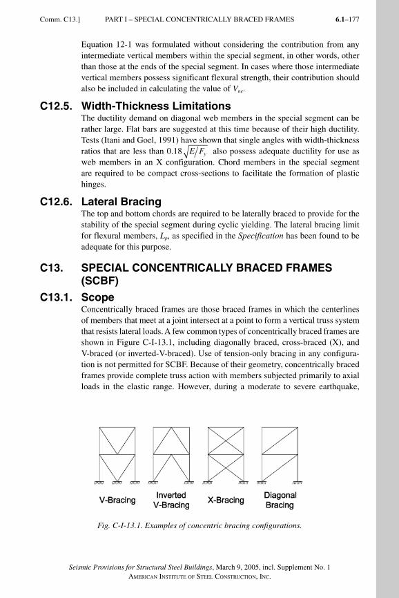
6.1–177
Seismic Provisions for Structural Steel Buildings, March 9, 2005, incl. Supplement No. 1AMERICAN INSTITUTE OF STEEL CONSTRUCTION, INC.
Comm. C13.] PART I – SPECIAL CONCENTRICALLY BRACED FRAMES
Equation 12-1 was formulated without considering the contribution from any intermediate vertical members within the special segment, in other words, other than those at the ends of the special segment. In cases where those intermediate vertical members possess significant flexural strength, their contribution should also be included in calculating the value of Vne.
C12.5. Width-Thickness LimitationsThe ductility demand on diagonal web members in the special segment can be rather large. Flat bars are suggested at this time because of their high ductility. Tests (Itani and Goel, 1991) have shown that single angles with width-thickness ratios that are less than 0.18 E Fy also possess adequate ductility for use as web members in an X configuration. Chord members in the special segment are required to be compact cross-sections to facilitate the formation of plastic hinges.
C12.6. Lateral BracingThe top and bottom chords are required to be laterally braced to provide for the stability of the special segment during cyclic yielding. The lateral bracing limit for flexural members, Lp, as specified in the Specification has been found to be adequate for this purpose.
C13. SPECIAL CONCENTRICALLY BRACED FRAMES (SCBF)
C13.1. ScopeConcentrically braced frames are those braced frames in which the centerlines of members that meet at a joint intersect at a point to form a vertical truss system that resists lateral loads. A few common types of concentrically braced frames are shown in Figure C-I-13.1, including diagonally braced, cross-braced (X), and V-braced (or inverted-V-braced). Use of tension-only bracing in any configura-tion is not permitted for SCBF. Because of their geometry, concentrically braced frames provide complete truss action with members subjected primarily to axial loads in the elastic range. However, during a moderate to severe earthquake,
Fig. C-I-13.1. Examples of concentric bracing configurations.
SeismicProvComm1.indd 177SeismicProvComm1.indd 177 9/8/06 3:13:23 PM9/8/06 3:13:23 PMProcess BlackProcess Black
Seismic Provisions for Structural Steel Buildings, March 9, 2005, incl. Supplement No. 1AMERICAN INSTITUTE OF STEEL CONSTRUCTION, INC.
6.1–178
the bracing members and their connections are expected to undergo significant inelastic deformations into the post-buckling range.
Since the initial adoption of concentrically braced frames into seismic design codes, more emphasis has been placed on increasing brace strength and stiffness, primarily through the use of higher design loads in order to minimize inelastic demand. More recently, requirements for ductility and energy dissipation capa-bility have also been added. Accordingly, provisions for special concentrically braced frames (SCBF) were developed to exhibit stable and ductile behavior in the event of a major earthquake. Earlier design provisions have been retained for ordinary concentrically braced frames (OCBF) in Section 14.
During a severe earthquake, bracing members in a concentrically braced frameare subjected to large deformations in cyclic tension and compression into the post-buckling range. As a result, reversed cyclic rotations occur at plastic hinges in much the same way as they do in beams and columns in moment frames. In fact, braces in a typical concentrically braced frame can be expected to yield and buckle at rather moderate story drifts of about 0.3 percent to 0.5 percent. In a severe earthquake, the braces could undergo post-buckling axial deformations 10 to 20 times their yield deformation. In order to survive such large cyclic de-formations without premature failure the bracing members and their connections must be properly detailed.
Damage during past earthquakes and that observed in laboratory tests of concen-trically braced frames has generally resulted from the limited ductility and corre-sponding brittle failures, which are usually manifested in the fracture of connec-tion elements or bracing members. The lack of compactness in braces results in severe local buckling, resulting in a high concentration of flexural strains at these locations and reduced ductility. Braces in concentrically braced frames are sub-ject to severe local buckling, with diminished effectiveness in the nonlinear range at low story drifts. Large story drifts that result from early brace fractures can im-pose excessive ductility demands on the beams and columns, or their connections.
Research has demonstrated that concentrically braced frames, with proper con-figuration, member design and detailing can possess ductility far in excess of that previously ascribed to such systems. Extensive analytical and experimental work by Goel and others has shown that improved design parameters, such as limiting width/thickness ratios (to minimize local buckling), closer spacing of stitches, and special design and detailing of end connections greatly improve the post-buckling behavior of concentrically braced frames (Goel, 1992b; Goel, 1992c). The design requirements for SCBF are based on those developments.
Previous requirements for concentrically braced frames sought reliable behavior by limiting global buckling. Cyclic testing of diagonal bracing systems verifies that energy can be dissipated after the onset of global buckling if brittle failures due to local buckling, stability problems and connection fractures are prevented. When properly detailed for ductility as prescribed in the Provisions, diagonal
PART I – SPECIAL CONCENTRICALLY BRACED FRAMES [Comm. C13.
SeismicProvComm1.indd 178SeismicProvComm1.indd 178 9/8/06 3:13:24 PM9/8/06 3:13:24 PMProcess BlackProcess Black
6.1–179
Seismic Provisions for Structural Steel Buildings, March 9, 2005, incl. Supplement No. 1AMERICAN INSTITUTE OF STEEL CONSTRUCTION, INC.
Comm. C13.] PART I – SPECIAL CONCENTRICALLY BRACED FRAMES
braces can sustain large inelastic cyclic deformations without experiencing pre-mature failures.
Analytical studies (Tang and Goel, 1987; Hassan and Goel, 1991) on bracing systems designed in strict accordance with earlier code requirements for con-centrically braced frames predicted brace failures without the development of significant energy dissipation. Failures occurred most often at plastic hinges (lo-cal buckling due to lack of compactness) or in the connections. Plastic hinges normally occur at the ends of a brace and at the brace midspan. Analytical mod-els of bracing systems that were designed to ensure stable ductile behavior when subjected to the same ground motion records as the previous concentrically braced frame designs exhibited full and stable hysteresis without fracture. Simi-lar results were observed in full-scale tests in Wallace and Krawinkler (1985) and Tang and Goel (1989).
For double-angle and double-channel braces, closer stitch spacing, in addition to more stringent compactness criteria, is required to achieve improved ductility and energy dissipation. This is especially critical for double-angle and double-channel braces that buckle imposing large shear forces on the stitches. Studies also showed that placement of double angles in a toe-to-toe configuration re-duces bending strains and local buckling (Aslani and Goel, 1991).
Many of the failures reported in concentrically braced frames due to strong ground motions have been in the connections. Similarly, cyclic testing of speci-mens designed and detailed in accordance with typical provisions for concentri-cally braced frames has produced connection failures (Astaneh-Asl, Goel and Hanson, 1986). Although typical design practice has been to design connections only for axial loads, good post-buckling response demands that eccentricities be accounted for in the connection design, which should be based upon the maxi-mum loads the connection may be required to resist. Good connection perfor-mance can be expected if the effects of brace member cyclic post-buckling be-havior are considered.
For brace buckling in the plane of the gusset plates, the end connections should be designed for the full axial load and flexural strength of the brace (Astaneh-Asl and others, 1986). Note that a realistic value of K should be used to represent the connection fixity.
For brace buckling out of the plane of single plate gussets, weak-axis bending in the gusset is induced by member end rotations. This results in flexible end conditions with plastic hinges at midspan in addition to the hinges that form in the gusset plate. Satisfactory performance can be ensured by allowing the gusset plate to develop restraint-free plastic rotations. This requires that the free length between the end of the brace and the assumed line of restraint for the gusset be sufficiently long to permit plastic rotations, yet short enough to preclude the oc-currence of plate buckling prior to member buckling. A length of two times the plate thickness is recommended (Astaneh-Asl and others, 1986). Note that this free distance is measured from the end of the brace to a line that is perpendicular
SeismicProvComm1.indd 179SeismicProvComm1.indd 179 9/8/06 3:13:24 PM9/8/06 3:13:24 PMProcess BlackProcess Black
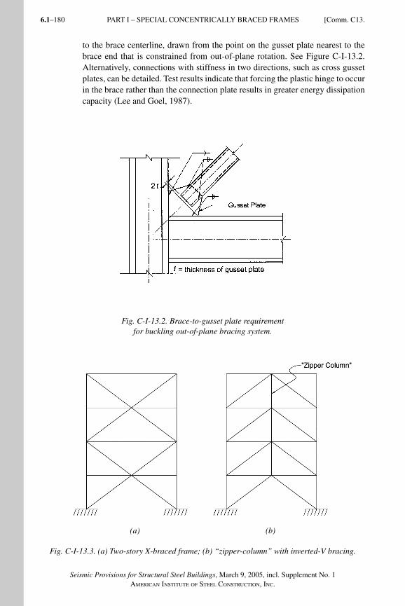
Seismic Provisions for Structural Steel Buildings, March 9, 2005, incl. Supplement No. 1AMERICAN INSTITUTE OF STEEL CONSTRUCTION, INC.
6.1–180
to the brace centerline, drawn from the point on the gusset plate nearest to the brace end that is constrained from out-of-plane rotation. See Figure C-I-13.2. Alternatively, connections with stiffness in two directions, such as cross gusset plates, can be detailed. Test results indicate that forcing the plastic hinge to occur in the brace rather than the connection plate results in greater energy dissipation capacity (Lee and Goel, 1987).
Fig. C-I-13.2. Brace-to-gusset plate requirement for buckling out-of-plane bracing system.
(a) (b)
Fig. C-I-13.3. (a) Two-story X-braced frame; (b) “zipper-column” with inverted-V bracing.
PART I – SPECIAL CONCENTRICALLY BRACED FRAMES [Comm. C13.
SeismicProvComm1.indd 180SeismicProvComm1.indd 180 9/8/06 3:13:24 PM9/8/06 3:13:24 PMProcess BlackProcess Black
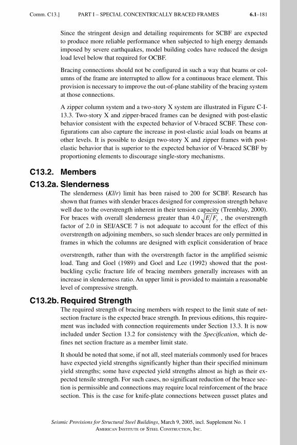
6.1–181
Seismic Provisions for Structural Steel Buildings, March 9, 2005, incl. Supplement No. 1AMERICAN INSTITUTE OF STEEL CONSTRUCTION, INC.
Since the stringent design and detailing requirements for SCBF are expected to produce more reliable performance when subjected to high energy demands imposed by severe earthquakes, model building codes have reduced the design load level below that required for OCBF.
Bracing connections should not be configured in such a way that beams or col-umns of the frame are interrupted to allow for a continuous brace element. This provision is necessary to improve the out-of-plane stability of the bracing system at those connections.
A zipper column system and a two-story X system are illustrated in Figure C-I-13.3. Two-story X and zipper-braced frames can be designed with post-elastic behavior consistent with the expected behavior of V-braced SCBF. These con-figurations can also capture the increase in post-elastic axial loads on beams at other levels. It is possible to design two-story X and zipper frames with post-elastic behavior that is superior to the expected behavior of V-braced SCBF by proportioning elements to discourage single-story mechanisms.
C13.2. Members
C13.2a. SlendernessThe slenderness (Kl/r) limit has been raised to 200 for SCBF. Research has shown that frames with slender braces designed for compression strength behave well due to the overstrength inherent in their tension capacity (Tremblay, 2000). For braces with overall slenderness greater than 4.0 E Fy , the overstrength factor of 2.0 in SEI/ASCE 7 is not adequate to account for the effect of this overstrength on adjoining members, so such slender braces are only permitted in frames in which the columns are designed with explicit consideration of brace
overstrength, rather than with the overstrength factor in the amplified seismic load. Tang and Goel (1989) and Goel and Lee (1992) showed that the post-buckling cyclic fracture life of bracing members generally increases with an increase in slenderness ratio. An upper limit is provided to maintain a reasonable level of compressive strength.
C13.2b. Required StrengthThe required strength of bracing members with respect to the limit state of net-section fracture is the expected brace strength. In previous editions, this require-ment was included with connection requirements under Section 13.3. It is now included under Section 13.2 for consistency with the Specification, which de-fines net section fracture as a member limit state.
It should be noted that some, if not all, steel materials commonly used for braces have expected yield strengths significantly higher than their specified minimum yield strengths; some have expected yield strengths almost as high as their ex-pected tensile strength. For such cases, no significant reduction of the brace sec-tion is permissible and connections may require local reinforcement of the brace section. This is the case for knife-plate connections between gusset plates and
Comm. C13.] PART I – SPECIAL CONCENTRICALLY BRACED FRAMES
SeismicProvComm1.indd 181SeismicProvComm1.indd 181 9/8/06 3:13:25 PM9/8/06 3:13:25 PMProcess BlackProcess Black
Seismic Provisions for Structural Steel Buildings, March 9, 2005, incl. Supplement No. 1AMERICAN INSTITUTE OF STEEL CONSTRUCTION, INC.
6.1–182
ASTM A53 or A500 braces [for example, pipe braces or square, rectangular or round hollow structural sections (HSS) braces], where the over-slot of the brace required for erection leaves a reduced section. If this section is left unreinforced, net section fracture will be the governing limit state and brace ductility may be significantly reduced (Korol, 1996; Cheng, Kulak and Khoo, 1998). Reinforce-ment may be provided in the form of steel plates welded to the tube, increasing the effective area at the reduced brace section (Yang and Mahin, 2005). Braces with two continuous welds to the gusset wrapped around its edge (instead of the more typical detail with four welds stopping short of the gusset edge) performed adequately in the tests by Cheng. However, this practice may be difficult to implement in field conditions; it also creates a potential stress riser that may lead to crack initiation.
Where there is no reduction in the section, or where the section is reinforced so that the effective net section is at least as great as the brace gross section, this requirement does not apply. The purpose of the requirement is to prevent net section fracture prior to significant ductility; having no reduction in the section is deemed sufficient to ensure this behavior. Reinforcement, if present, should be connected to the brace in a manner that is consistent with the assumed state of stress in the design. It is recommended that the connection of the reinforcement to the brace be designed for the strength of the reinforcement on either side of the reduced section.
C13.2c. Lateral Force DistributionThis provision attempts to balance the tensile and compressive resistance across the width and breadth of the building since the buckling and post-buckling strength of the bracing members in compression can be substantially less than that in tension. Good balance helps prevent the accumulation of inelastic drifts in one direction. An exception is provided for cases where the bracing members are sufficiently oversized to provide essentially elastic response.
C13.2d. Width-Thickness Limitations Traditionally, braces have shown little or no ductility after overall (member) buck-ling, which produces a plastic hinge at the brace midpoint. At this plastic hinge, local buckling can cause large strains, leading to fracture at low drifts. It has been found that braces with compact elements are capable of achieving signifi-cantly more ductility by forestalling local buckling (Goel, 1992b; Hassan and Goel, 1991; Tang and Goel, 1989). Width-thickness ratios of compression ele-ments in bracing members have been set to be at or below the requirements for compact sections in order to minimize the detrimental effects of local buckling and subsequent fracture during repeated inelastic cycles.
Tests have shown fracture due to local buckling is especially prevalent in rectan-gular HSS with width-thickness ratios larger than the prescribed limits (Hassan and Goel, 1991; Tang and Goel, 1989). Even for square HSS braces designed to meet the seismic width-thickness ratios of these Provisions, local buckling
PART I – SPECIAL CONCENTRICALLY BRACED FRAMES [Comm. C13.
SeismicProvComm1.indd 182SeismicProvComm1.indd 182 9/8/06 3:13:25 PM9/8/06 3:13:25 PMProcess BlackProcess Black
6.1–183
Seismic Provisions for Structural Steel Buildings, March 9, 2005, incl. Supplement No. 1AMERICAN INSTITUTE OF STEEL CONSTRUCTION, INC.
leading to fracture may represent a limitation on the performance (Yang and Mahin, 2005).
The same limitations apply to columns in SCBF, as their flexural strength and rotation capacity, and has been shown to be a significant contributor to the stabil-ity of SCBF (Tremblay, 2001, 2003). It has also been demonstrated that SCBF can be subject to significant interstory drift (Sabelli, Mahin and Chang, 2003), requiring columns to undergo inelastic rotation.
Enhanced ductility and fracture life of rectangular hollow structural sections (HSS) bracing members can be achieved in a variety of ways. The tube walls can be stiffened by using longitudinal stiffeners, such as rib plates or small angle sections in a hat configuration (Liu and Goel, 1987). Use of plain concrete infill has been found to be quite effective in reducing the severity of local buckling in the post-buckling range of the member (Liu and Goel, 1988; Lee and Goel, 1987). Based on their test results, Goel and Lee (1992) formulated an empiri-cal equation to determine the effective width-thickness ratio of concrete-filled rectangular tubular bracing members. The effective width-thickness ratio can be calculated by multiplying the actual width-thickness ratio by a factor, [(0.0082 × KL/r) + 0.264], for KL/r between 35 and 90, KL/r being the effective slender-ness ratio of the member. The purpose of concrete infill as described herein is to inhibit the detrimental effects of local buckling of the tube walls. Use of concrete to achieve composite action of braces is covered in Part II, Section 13.4.
As an alternative to using a single large HSS, consideration may be given to using double smaller tube sections stitched together and connected at the ends to a single gusset plate (or cross shape if needed) in much the same way as double angle or channel sections are used in a back-to-back configuration (Lee and Goel, 1990). Such double tube sections offer a number of advantages, including reduced fit-up problems, smaller width-thickness ratio for the same overall width of the section, in-plane buckling in most cases eliminating the problem of out-of-plane bending of gusset plates, greater energy dissipation as three plastic hinges form in the member, and greater strength because of effec-tive length factor, K, being close to 0.5 as opposed to K=1.0 when out-of-plane buckling occurs in a single tube and single gusset plate member.
C13.2e. Built-up MembersCloser spacing of stitches and higher stitch strength requirements are specified for built-up bracing members in SCBF (Aslani and Goel, 1991; Xu and Goel, 1990) than those required for OCBF. These are intended to restrict individual element bending between the stitch points and consequent premature fracture of bracing members. Wider spacing is permitted under an exception when buckling does not cause shear in the stitches. Bolted stitches are not permitted within the middle one-fourth of the clear brace length as the presence of bolt holes in that region may cause premature fractures due to the formation of a plastic hinge in the post-buckling range.
Comm. C13.] PART I – SPECIAL CONCENTRICALLY BRACED FRAMES
SeismicProvComm1.indd 183SeismicProvComm1.indd 183 9/8/06 3:13:26 PM9/8/06 3:13:26 PMProcess BlackProcess Black
Seismic Provisions for Structural Steel Buildings, March 9, 2005, incl. Supplement No. 1AMERICAN INSTITUTE OF STEEL CONSTRUCTION, INC.
6.1–184
C13.3. Required Strength of Bracing Connections
C13.3a. Required Tensile StrengthBraces in SCBF are required to have gross-section tensile yielding as their gov-erning limit state so that they will yield in a ductile manner. Local connection failure modes such as block shear rupture must be precluded. Therefore, the calculations for these failure modes must use the maximum load that the brace can develop.
The minimum of two criteria (in other words, the nominal expected axial tension strength of the bracing member and the maximum force that could be developed by the overall system) determines the required strength of both the bracing con-nection and the beam-to-column connection if it is part of the bracing system. This upper limit is included in the specification for structures where elements other than the tension bracing limit the system strength; for example, foundation elements designed in systems based on the application of load combinations using the amplified seismic load. Ry has been added to the first provision to rec-ognize the expected strength of the member material.
The provisions in both Sections 13.3a and 14.4 allow the connection design force to be limited by the maximum force that the system can transfer to the connec-tion. Depending on the specific situation(s), there are a number of ways one can determine the maximum force transferred to the connection. They include
(1) Perform a pushover analysis to determine the forces acting on the connec-tions when the maximum frame capacity (leading to an imminent collapse mechanism) is reached.
(2) Determine how much force can be resisted before causing uplift of a spread footing (note that the foundation design forces are not required to resist more than the code base shear level). This type of relief is not typically applicable to a deep foundation since the determination of when uplift will occur is not easy to determine with good accuracy.
(3) Perform a suite of inelastic time history analyses and envelop the connec-tion demands.
Calculating the maximum connection force by one of the three methods noted above is not a common practice on design projects. In some cases, such an ap-proach could result in smaller connection demands. But, from a conceptual ba-sis, since the character of the ground motions is not known to any great extent, it is unrealistic to expect that such forces can be accurately calculated. All three ap-proaches rely on an assumed distribution of lateral forces which may not match reality (approach #3 probably being the best estimate, but also the most calcu-lation intensive). In most cases, providing the connection with a capacity large enough to yield the member is needed because of the large inelastic demands placed on a structure by a major earthquake.
Requirements specific to member net section fracture have been moved to Section 13.2b.
PART I – SPECIAL CONCENTRICALLY BRACED FRAMES [Comm. C13.
SeismicProvComm1.indd 184SeismicProvComm1.indd 184 9/8/06 3:13:26 PM9/8/06 3:13:26 PMProcess BlackProcess Black
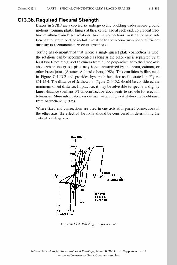
6.1–185
Seismic Provisions for Structural Steel Buildings, March 9, 2005, incl. Supplement No. 1AMERICAN INSTITUTE OF STEEL CONSTRUCTION, INC.
C13.3b. Required Flexural StrengthBraces in SCBF are expected to undergo cyclic buckling under severe ground motions, forming plastic hinges at their center and at each end. To prevent frac-ture resulting from brace rotations, bracing connections must either have suf-ficient strength to confine inelastic rotation to the bracing member or sufficient ductility to accommodate brace-end rotations.
Testing has demonstrated that where a single gusset plate connection is used, the rotations can be accommodated as long as the brace end is separated by at least two times the gusset thickness from a line perpendicular to the brace axis about which the gusset plate may bend unrestrained by the beam, column, or other brace joints (Astaneh-Asl and others, 1986). This condition is illustrated in Figure C-I-13.2 and provides hysteretic behavior as illustrated in Figure C-I-13.4. The distance of 2t shown in Figure C-I-13.2 should be considered the minimum offset distance. In practice, it may be advisable to specify a slightly larger distance (perhaps 3t) on construction documents to provide for erection tolerances. More information on seismic design of gusset plates can be obtained from Astaneh-Asl (1998).
Where fixed end connections are used in one axis with pinned connections in the other axis, the effect of the fixity should be considered in determining the critical buckling axis.
Fig. C-I-13.4. P-δ diagram for a strut.
Comm. C13.] PART I – SPECIAL CONCENTRICALLY BRACED FRAMES
SeismicProvComm1.indd 185SeismicProvComm1.indd 185 9/8/06 3:13:26 PM9/8/06 3:13:26 PMProcess BlackProcess Black
Seismic Provisions for Structural Steel Buildings, March 9, 2005, incl. Supplement No. 1AMERICAN INSTITUTE OF STEEL CONSTRUCTION, INC.
6.1–186
C13.4. Special Bracing Configuration Requirements
C13.4a. V-Type and Inverted V-Type BracingV-braced and inverted-V-braced frames exhibit a special problem that sets them apart from braced frames in which both ends of the braces frame into beam-column connections. The expected behavior of SCBF is that upon continued lat-eral displacement as the brace in compression buckles, its force drops while that in the brace in tension continues to increase up to the point of yielding. In order for this to occur, an unbalanced vertical force must be resisted by the intersecting beam, as well as its connections and supporting members. In order to prevent undesirable deterioration of lateral strength of the frame, the SCBF provisions require that the beam possess adequate strength to resist this potentially significant post-buckling load redistribution (the unbalanced load) in combination with appropriate gravity loads. Tests have shown that typical bracing members demonstrate a minimum residual post-buckling compressive strength of about 30 percent of the initial compressive strength (Hassan and Goel, 1991). [Al-though very slender braces can have a higher post-buckling resistance, the effect of this additional strength on reducing the unbalance force is negligible. Very stocky braces (those with slenderness ratios below 60) can also have higher post-buckling resistance, but such braces are not typically used in buildings.] This is the maximum compression load that should be combined with the full yield load of the adjacent tension brace. The full tension load can be expected to be in the range of RyPy. In addition, configurations where the beam-to-brace connection is significantly offset from the midspan location should be avoided whenever possi-ble, since such a configuration exacerbates the unbalanced conditions cited above.
The adverse effect of this unbalanced load can be mitigated by using bracing configurations, such as V- and inverted-V-braces in alternate stories creating an X-configuration over two story modules, or by using a “zipper column” with V- or inverted-V bracing (Khatib, Mahin and Pister, 1988). See Figure C-I-13.3.
Adequate lateral bracing at the brace-to-beam intersection is necessary in order to prevent adverse effects of possible lateral-torsional buckling of the beam. The stability of this connection is influenced by the flexural and axial forces in the beam, as well as by any torsion imposed by brace buckling or the post-buckling residual out-of-straightness of a brace. The committee did not believe that under these conditions the bracing requirements in the Specification are sufficient to ensure the torsional stability of this connection. Therefore a requirement based on the moment due to the flexural strength of the beam is imposed.
C13.4b. K-Type BracingK-bracing is generally not considered desirable in concentrically braced frames and is prohibited entirely for SCBF because it is considered undesirable to have columns that are subjected to unbalanced lateral forces from the braces, as these forces may contribute to column failures.
PART I – SPECIAL CONCENTRICALLY BRACED FRAMES [Comm. C13.
SeismicProvComm1.indd 186SeismicProvComm1.indd 186 9/8/06 3:13:27 PM9/8/06 3:13:27 PMProcess BlackProcess Black
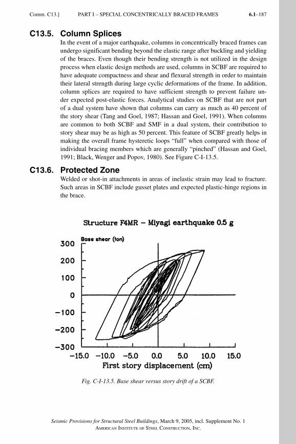
6.1–187
Seismic Provisions for Structural Steel Buildings, March 9, 2005, incl. Supplement No. 1AMERICAN INSTITUTE OF STEEL CONSTRUCTION, INC.
C13.5. Column SplicesIn the event of a major earthquake, columns in concentrically braced frames can undergo significant bending beyond the elastic range after buckling and yielding of the braces. Even though their bending strength is not utilized in the design process when elastic design methods are used, columns in SCBF are required to have adequate compactness and shear and flexural strength in order to maintain their lateral strength during large cyclic deformations of the frame. In addition, column splices are required to have sufficient strength to prevent failure un-der expected post-elastic forces. Analytical studies on SCBF that are not part of a dual system have shown that columns can carry as much as 40 percent of the story shear (Tang and Goel, 1987; Hassan and Goel, 1991). When columns are common to both SCBF and SMF in a dual system, their contribution to story shear may be as high as 50 percent. This feature of SCBF greatly helps in making the overall frame hysteretic loops “full” when compared with those of individual bracing members which are generally “pinched” (Hassan and Goel, 1991; Black, Wenger and Popov, 1980). See Figure C-I-13.5.
C13.6. Protected ZoneWelded or shot-in attachments in areas of inelastic strain may lead to fracture. Such areas in SCBF include gusset plates and expected plastic-hinge regions in the brace.
Fig. C-I-13.5. Base shear versus story drift of a SCBF.
Comm. C13.] PART I – SPECIAL CONCENTRICALLY BRACED FRAMES
SeismicProvComm1.indd 187SeismicProvComm1.indd 187 9/8/06 3:13:27 PM9/8/06 3:13:27 PMProcess BlackProcess Black
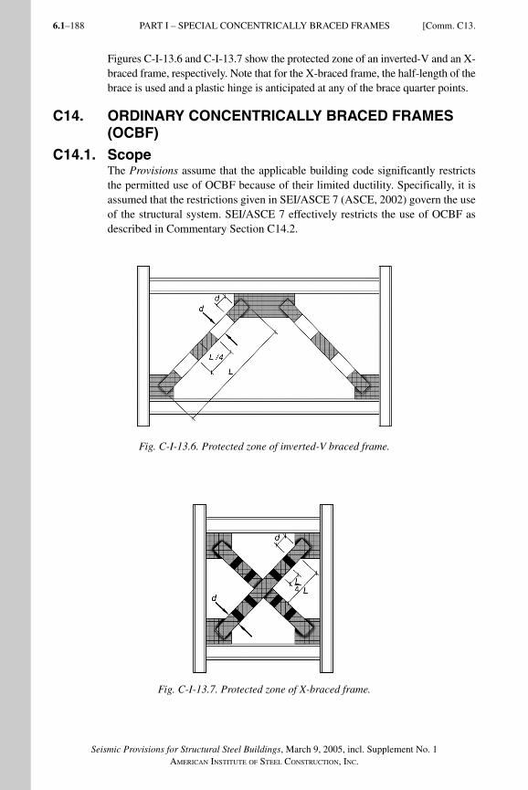
Seismic Provisions for Structural Steel Buildings, March 9, 2005, incl. Supplement No. 1AMERICAN INSTITUTE OF STEEL CONSTRUCTION, INC.
6.1–188
Figures C-I-13.6 and C-I-13.7 show the protected zone of an inverted-V and an X-braced frame, respectively. Note that for the X-braced frame, the half-length of the brace is used and a plastic hinge is anticipated at any of the brace quarter points.
C14. ORDINARY CONCENTRICALLY BRACED FRAMES (OCBF)
C14.1. ScopeThe Provisions assume that the applicable building code significantly restricts the permitted use of OCBF because of their limited ductility. Specifically, it is assumed that the restrictions given in SEI/ASCE 7 (ASCE, 2002) govern the use of the structural system. SEI/ASCE 7 effectively restricts the use of OCBF as described in Commentary Section C14.2.
Fig. C-I-13.6. Protected zone of inverted-V braced frame.
Fig. C-I-13.7. Protected zone of X-braced frame.
PART I – SPECIAL CONCENTRICALLY BRACED FRAMES [Comm. C13.
SeismicProvComm1.indd 188SeismicProvComm1.indd 188 9/8/06 3:13:27 PM9/8/06 3:13:27 PMProcess BlackProcess Black
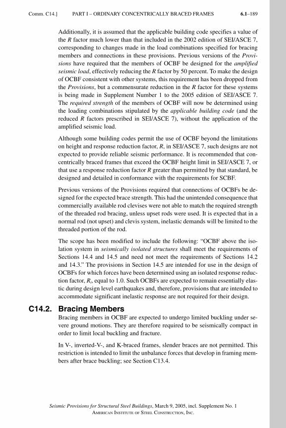
6.1–189
Seismic Provisions for Structural Steel Buildings, March 9, 2005, incl. Supplement No. 1AMERICAN INSTITUTE OF STEEL CONSTRUCTION, INC.
Comm. C14.] PART I – ORDINARY CONCENTRICALLY BRACED FRAMES
Additionally, it is assumed that the applicable building code specifies a value of the R factor much lower than that included in the 2002 edition of SEI/ASCE 7, corresponding to changes made in the load combinations specified for bracing members and connections in these provisions. Previous versions of the Provi-sions have required that the members of OCBF be designed for the amplified seismic load, effectively reducing the R factor by 50 percent. To make the design of OCBF consistent with other systems, this requirement has been dropped from the Provisions, but a commensurate reduction in the R factor for these systems is being made in Supplement Number 1 to the 2005 edition of SEI/ASCE 7. The required strength of the members of OCBF will now be determined using the loading combinations stipulated by the applicable building code (and the reduced R factors prescribed in SEI/ASCE 7), without the application of the amplified seismic load.
Although some building codes permit the use of OCBF beyond the limitations on height and response reduction factor, R, in SEI/ASCE 7, such designs are not expected to provide reliable seismic performance. It is recommended that con-centrically braced frames that exceed the OCBF height limit in SEI/ASCE 7, or that use a response reduction factor R greater than permitted by that standard, be designed and detailed in conformance with the requirements for SCBF.
Previous versions of the Provisions required that connections of OCBFs be de-signed for the expected brace strength. This had the unintended consequence that commercially available rod clevises were not able to match the required strength of the threaded rod bracing, unless upset rods were used. It is expected that in a normal rod (not upset) and clevis system, inelastic demands will be limited to the threaded portion of the rod.
The scope has been modified to include the following: “OCBF above the iso-lation system in seismically isolated structures shall meet the requirements of Sections 14.4 and 14.5 and need not meet the requirements of Sections 14.2 and 14.3.” The provisions in Section 14.5 are intended for use in the design of OCBFs for which forces have been determined using an isolated response reduc-tion factor, Ri, equal to 1.0. Such OCBFs are expected to remain essentially elas-tic during design level earthquakes and, therefore, provisions that are intended to accommodate significant inelastic response are not required for their design.
C14.2. Bracing MembersBracing members in OCBF are expected to undergo limited buckling under se-vere ground motions. They are therefore required to be seismically compact in order to limit local buckling and fracture.
In V-, inverted-V-, and K-braced frames, slender braces are not permitted. This restriction is intended to limit the unbalance forces that develop in framing mem-bers after brace buckling; see Section C13.4.
SeismicProvComm1.indd 189SeismicProvComm1.indd 189 9/8/06 3:13:28 PM9/8/06 3:13:28 PMProcess BlackProcess Black
Seismic Provisions for Structural Steel Buildings, March 9, 2005, incl. Supplement No. 1AMERICAN INSTITUTE OF STEEL CONSTRUCTION, INC.
6.1–190
C14.3. Special Bracing Configuration RequirementsSimilar to K-type bracing, V- and inverted-V-type bracing can induce a high unbalanced force in the intersecting beam. Unlike the SCBF provisions, which require that the beams at the intersections of such braces be designed for the expected yield strength of the braces to prevent a plastic hinge mechanism in the beam, the corresponding OCBF provisions permit the beam design on the basis of the maximum force that can be developed by the system. This relief for OCBF acknowledges that, unlike SCBF, the beam forces in an OCBF frame at the time of an imminent system failure mode could be less critical than those due to the expected yield strength of the connecting braces. See the commentary for Sections 13.3a(b) and 14.4(a) for techniques that may be used to determine the maximum force developed by the system.
C14.4. Bracing ConnectionsBracing connections are designed for forces corresponding to the expected brace strength, the maximum force that the system can develop (see Commentary Sec-tion C13.3 for discussion), or the amplified seismic load so as to delay the con-nection limit state. Net section fracture of the member is to be included with connection limit states and designed for the amplified seismic load. This edition of the Provisions permit the required strength of a brace connection in an OCBF to not exceed the load effect based on the amplified seismic load. It is noted that the use of amplified seismic load for brace connection was allowed in the 1992 Seismic Provisions for Structural Steel Buildings; however, it was removed from the 1997 and 2002 Seismic Provisions for Structural Steel Buildings because of a concern that Ωo, the prescribed global overstrength factor may not be ap-propriate because, in moderate to high ductility seismic load resisting systems, individual connections can experience forces much higher than the amplified seismic load in order for the frame to achieve its maximum overall capacity. On the other hand, the approach based on the amplified seismic load is considered appropriate for systems designed for limited ductility. As noted in Commentary Section C14.1, OCBFs will now be designed for a low enough R-value to clas-sify it as a low-ductility system so that the design of its brace connections for amplified seismic loads is now deemed acceptable.
The Provisions permit that bolt slip be designed for a lower force level than is required for other limit states. This reflects the fact that bolt slip does not con-stitute connection failure and that the associated energy dissipation can serve to reduce seismic response.
C14.5. OCBF above Seismic Isolation Systems
C14.5a. Bracing MembersThe requirements in this section are similar to Section 14.2, except that the KL/r limitation is applied to all braces. Tension-only bracing is not considered to be appropriate for use above isolation systems under the conditions permitted.
PART I – ORDINARY CONCENTRICALLY BRACED FRAMES [Comm. C14.
SeismicProvComm1.indd 190SeismicProvComm1.indd 190 9/8/06 3:13:28 PM9/8/06 3:13:28 PMProcess BlackProcess Black
6.1–191
Seismic Provisions for Structural Steel Buildings, March 9, 2005, incl. Supplement No. 1AMERICAN INSTITUTE OF STEEL CONSTRUCTION, INC.
Comm. C15.] PART I – ECCENTRICALLY BRACED FRAMES
C14.5b. K-Type BracingK-type bracing is not considered appropriate for use above isolation systems under the conditions permitted.
C14.5c. V-Type and Inverted-V-Type BracingThe requirements of Section 14.3 are considered to be excessive for OCBFs above the isolation system because the forces on the system are limited and buckling of braces is not anticipated. The only requirement is for the beams to be continuous between columns.
C15. ECCENTRICALLY BRACED FRAMES (EBF)
C15.1. ScopeResearch has shown that eccentrically braced frames (EBF) can provide an elas-tic stiffness that is comparable to that of special concentrically braced frames (SCBF) and ordinary concentrically braced frames (OCBF), particularly when short link lengths are used, and excellent ductility and energy dissipation capac-ity in the inelast ic range, comparable to that of special moment frames (SMF), provided that the links are not too short (Roeder and Popov; 1978; Libby, 1981; Merovich, Nicoletti and Hartle, 1982; Hjelmstad and Popov, 1983; Malley and Popov, 1984; Kasai and Popov, 1986a, 1986b; Ricles and Popov, 1987a, 1987b; Engelhardt and Popov, 1989a, 1989b; Popov, Engelhardt and Ricles, 1989). EBF are composed of columns, beams and braces. The distinguishing characteris-tic of an EBF is that at least one end of every brace is connected so that the brace force is transmitted through shear and bending of a short beam segment called the link. Figure C-I-15.1 illustrates some examples of eccentrically braced frames. Inelastic action in EBF under seismic loading is restricted primarily to the links. These provi sions are intended to ensure that cyclic yield ing in the links can occur in a stable manner while the diagonal braces, columns, and portions of the beam outside of the link remain essentially elastic u n d er the f o r c es t h a t c an be developed by fu l ly yi e l ded a nd s t r a in-h a r d e n ed links.
Figure C-I-15.1 identifies the key components of an EBF: the links, the beam segments outside of the links, the diagonal braces, and the columns. Require-ments for links are provided in Sections 15.2 to 15.5; requirements for beam seg-ments outside of the links and for the diagonal braces are provided in Sections 15.6 and 15.7; requirements for columns are provided in Section 15.8.
In some bracing arrangements, such as that illustrated in Figure C-I-15.2 with links at each end of the brace, links may not be fully effective. If the upper link has a significantly lower design shear strength than that for the link in the story below, the upper link will deform inelastically and limit the force that can be developed in the brace and to the lower link. When this condition occurs the upper link is termed an active link and the lower link is termed an inactive link. The presence of potentially inactive links in an EBF increases the difficulty of analysis.
SeismicProvComm1.indd 191SeismicProvComm1.indd 191 9/8/06 3:13:28 PM9/8/06 3:13:28 PMProcess BlackProcess Black
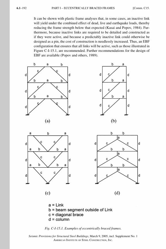
Seismic Provisions for Structural Steel Buildings, March 9, 2005, incl. Supplement No. 1AMERICAN INSTITUTE OF STEEL CONSTRUCTION, INC.
6.1–192
It can be shown with plastic frame analyses that, in some cases, an inactive link will yield under the combined effect of dead, live and earthquake loads, thereby reducing the frame strength below that expected (Kasai and Popov, 1984). Fur-thermore, because inactive links are required to be detailed and constructed as if they were active, and because a predictably inactive link could otherwise be designed as a pin, the cost of construction is needlessly increased. Thus, an EBF configuration that ensures that all links will be active, such as those illustrated in Figure C-I-15.1, are recommended. Further recommendations for the design of EBF are available (Popov and others, 1989).
Fig. C-I-15.1. Examples of eccentrically braced frames.
PART I – ECCENTRICALLY BRACED FRAMES [Comm. C15.
SeismicProvComm1.indd 192SeismicProvComm1.indd 192 9/8/06 3:13:28 PM9/8/06 3:13:28 PMProcess BlackProcess Black
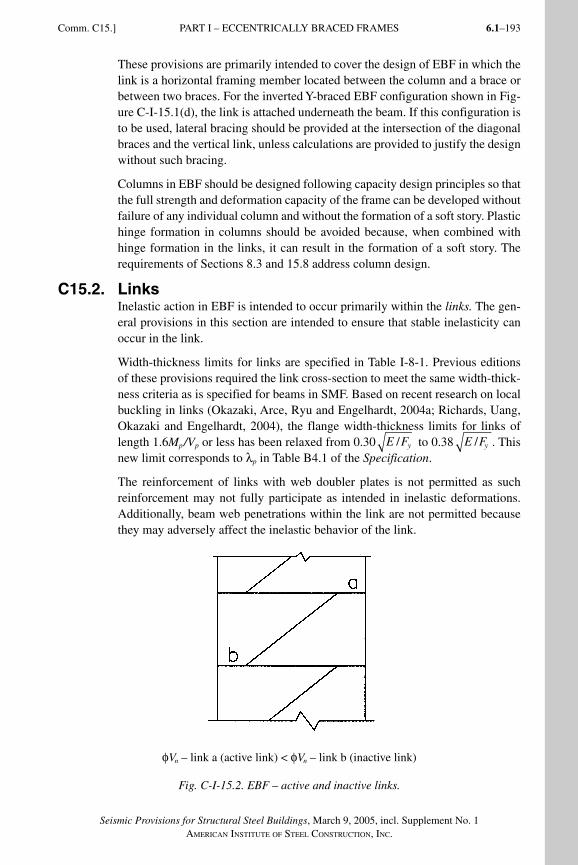
6.1–193
Seismic Provisions for Structural Steel Buildings, March 9, 2005, incl. Supplement No. 1AMERICAN INSTITUTE OF STEEL CONSTRUCTION, INC.
Comm. C15.] PART I – ECCENTRICALLY BRACED FRAMES
These provisions are primarily intended to cover the design of EBF in which the link is a horizontal framing member located between the column and a brace or between two braces. For the inverted Y-braced EBF configuration shown in Fig-ure C-I-15.1(d), the link is attached underneath the beam. If this configuration is to be used, lateral bracing should be provided at the intersection of the diagonal braces and the vertical link, unless calculations are provided to justify the design without such bracing.
Columns in EBF should be designed following capacity design principles so that the full strength and deformation capacity of the frame can be developed without failure of any individual column and without the formation of a soft story. Plastic hinge formation in columns should be avoided because, when combined with hinge formation in the links, it can result in the formation of a soft story. The requirements of Sections 8.3 and 15.8 address column design.
C15.2. LinksInelastic action in EBF is intended to occur primarily within the links. The gen-eral provisions in this section are intended to ensure that stable inelasticity can occur in the link.
Width-thickness limits for links are specified in Table I-8-1. Previous editions of these provisions required the link cross-section to meet the same width-thick-ness criteria as is specified for beams in SMF. Based on recent research on local buckling in links (Okazaki, Arce, Ryu and Engelhardt, 2004a; Richards, Uang, Okazaki and Engelhardt, 2004), the flange width-thickness limits for links of length 1.6Mp/Vp or less has been relaxed from 0.30 E Fy/ to 0.38 E Fy/ . This new limit corresponds to λp in Table B4.1 of the Specification.
The reinforcement of links with web doubler plates is not permitted as such reinforcement may not fully participate as intended in inelastic deformations. Additionally, beam web penetrations within the link are not permitted because they may adver sely affect the inelastic behavior of the link.
φVn – link a (active link) < φVn – link b (inactive link)
Fig. C-I-15.2. EBF – active and inactive links.
SeismicProvComm1.indd 193SeismicProvComm1.indd 193 9/8/06 3:13:29 PM9/8/06 3:13:29 PMProcess BlackProcess Black
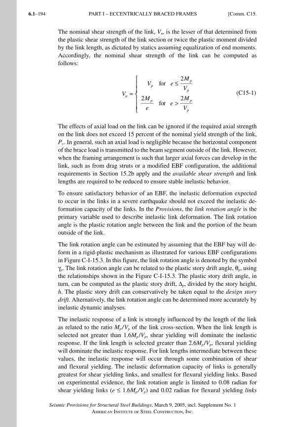
Seismic Provisions for Structural Steel Buildings, March 9, 2005, incl. Supplement No. 1AMERICAN INSTITUTE OF STEEL CONSTRUCTION, INC.
6.1–194
The nominal shear strength of the link, Vn, is the lesser of that deter mined from the plastic shear strength of the link section or twice the plastic moment divided by the link length, as dictated by statics assuming equalization of end moments. Accordingly, the nominal shear strength of the link can be computed as follows:
V
V for e M
V
M
e for e
M
V
n
p p
p
p p
p
=
≤
>
⎧
⎨ ⎪ ⎪
⎩ ⎪ ⎪
2
2 2 (C15-1)
The effects of axial load on the link can be ignored if the required axial strength on the link does not exceed 15 percent of the nominal yield strength of the link, Py. In gene ral, such an axial load is negli gible because the hori zontal compo nent of the brace load is transmitt ed to the beam segment outside of the link. However, when the framing arrangement is such that larger axial forces can develop in the link, such as from drag struts or a modified EBF configuration, the additional requirements in Section 15.2b apply and the available shear strength and link lengths are required to be reduced to ensure stable inelastic behavior.
To ensure satisfactory behavior of an EBF, the inelastic deformation expected to occur in the links in a severe earthquake should not exceed the inelastic de-formation capacity of the links. In the Provisions, the link rotation angle is the primary variable used to describe inelastic link deformation. The link rotation angle is the plastic rotation angle between the link and the portion of the beam outside of the link.
The link rotation angle can be estimated by assuming that the EBF bay will de-form in a rigid-plastic mechanism as illustrated for various EBF configurations in Figure C-I-15.3. In this figure, the link rotation angle is denoted by the symbol γp. The link rotation angle can be related to the plastic story drift angle, θp, using the relationships shown in the Figure C-I-15.3. The plastic story drift angle, in turn, can be computed as the plastic story drift, Δp, divided by the story height, h. The plastic story drift can conservatively be taken equal to the design story drift. Alternatively, the link rotation angle can be deter mined more accurately by inelastic dynamic analyses.
The inelastic response of a link is strongly influenced by the length of the link as related to the ratio Mp/Vp of the link cross-section. When the link length is selected not greater than 1.6Mp /Vp, shear yielding will dominate the inelastic response. If the link length is selected greater than 2.6Mp /Vp, flexural yielding will dominate the inelastic response. For link lengths intermediate between these values, the inelastic response will occur through some combination of shear and flexural yielding. The inelastic deformation capacity of links is generally greatest for shear yielding links, and smallest for flexural yielding links. Based on experimental evidence, the link rotation angle is limited to 0.08 radian for shear yielding links (e ≤ 1.6Mp/Vp) and 0.02 radian for flexural yielding links
PART I – ECCENTRICALLY BRACED FRAMES [Comm. C15.
SeismicProvComm1.indd 194SeismicProvComm1.indd 194 9/8/06 3:13:30 PM9/8/06 3:13:30 PMProcess BlackProcess Black
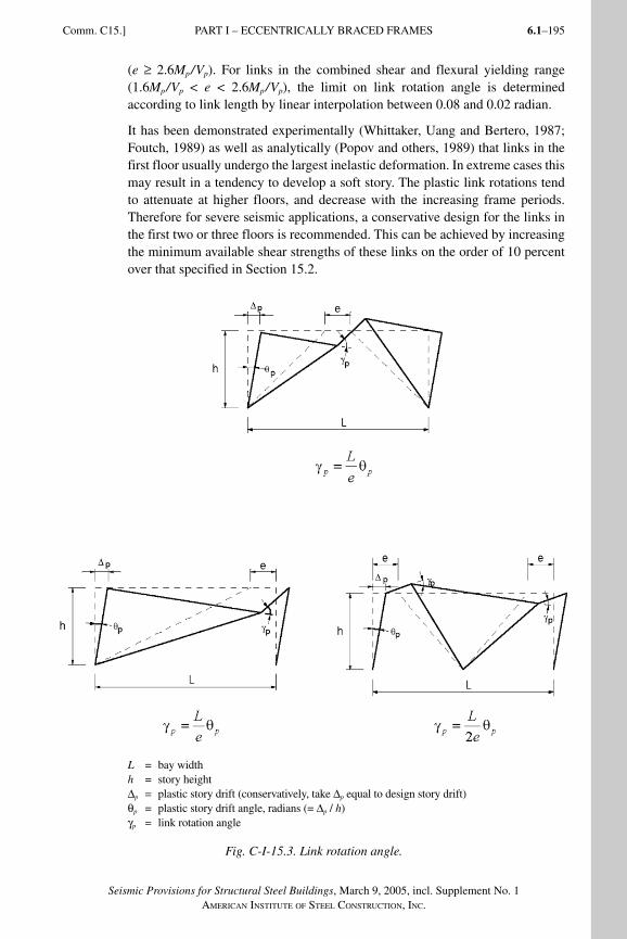
6.1–195
Seismic Provisions for Structural Steel Buildings, March 9, 2005, incl. Supplement No. 1AMERICAN INSTITUTE OF STEEL CONSTRUCTION, INC.
(e ≥ 2.6Mp/Vp). For links in the combined shear and flexural yielding range (1.6Mp/Vp < e < 2.6Mp/Vp), the limit on link rotation angle is determined according to link length by linear interpolation between 0.08 and 0.02 radian.
It has been demonstrated experimentally (Whittaker, Uang and Bertero, 1987; Foutch, 1989) as well as analyt ically (Popov and others, 1989) that links in the first floor usually undergo the largest inelastic deformation. In extreme cases this may result in a tendency to develop a soft story. The plastic link rotations tend to attenuate at higher floors, and decrease with the increasing frame periods. Therefore for severe seismic applications, a conservative design for the links in the first two or three floors is recommended. This can be achieved by increasing the minimum available shear strengths of these links on the order of 10 percent over that specified in Section 15.2.
L = bay widthh = story heightΔp = plastic story drift (conservatively, take Δp equal to design story drift)θp = plastic story drift angle, radians (= Δp / h)γp = link rotation angle
Fig. C-I-15.3. Link rotation angle.
Comm. C15.] PART I – ECCENTRICALLY BRACED FRAMES
SeismicProvComm1.indd 195SeismicProvComm1.indd 195 9/8/06 3:13:30 PM9/8/06 3:13:30 PMProcess BlackProcess Black
Seismic Provisions for Structural Steel Buildings, March 9, 2005, incl. Supplement No. 1AMERICAN INSTITUTE OF STEEL CONSTRUCTION, INC.
6.1–196
C15.3. Link StiffenersA properly detailed and restrained link web can provide stable, ductile, and predict able behavior under severe cyclic loading. The design of the link requires close attention to the detailing of the link web thickness and stiffeners.
Full-depth stif feners are requ ired at the ends of all links and serve to tran sfer the link shear forces to the reac ting elements as well as restrai n the link web against buckling.
The maximum spacing of link intermediate web stiffeners in shear yielding links (e ≤ 1.6Mp /Vp) is depe ndent upon the size of the link rotation angle (Kasai and Popov, 1986b) with a closer spacing required as the rotation angle increases. Intermediate web stiffeners in shear yielding links are provided to delay the on-set of inelastic shear buckling of the web. Flexural yielding links having lengths greater than 2.6Mp/Vp but less than 5Mp/Vp are required to have an inter mediate stiffener at a distance from the link end equal to 1.5 times the beam flange width to limit strength degradation due to flange local buckling and lateral-torsional buckling. Links of a length that are between the shear and flexural limits are required to meet the stiffener requirements for both shear and flexural yielding links. When the link length exceeds 5Mp/Vp, link inter mediate web stiffeners are not required. Link inter mediate web stiffeners are requ ired to extend full depth in order to effectively resist shear buckl ing of the web and to effectively limit strength degradation due to flange local buckling and lateral-torsional buckling. Link intermediate web stiffeners are required on both sides of the web for links 25 in. (635 mm) in depth or greater. For links that are less than 25 in. (635 mm) deep, the stiffener need be on one side only.
All link stiffeners are required to be fillet welded to the link web and flanges. Link stiffeners should be detailed to avoid welding in the k-area of the link. Recent research has indicated that stiffener-to-link web welds that extend into the k-area of the link can generate link web fractures that may reduce the plastic rotation capacity of the link (Okazaki and others, 2004a; Richards and others, 2004).
C15.4. Link-to-Column ConnectionsPrior to the 1994 Northridge Earthquake, link-to-column connections were typi-cally constructed in a manner substantially similar to beam-to-column connec-tions in SMF. Link-to-column connections in EBF are therefore likely to share many of the same problems observed in moment frame connections. Conse-quently, in a manner similar to beam-to-column connections in SMF, the Pro-visions require that the performance of link-to-column connections be verified by testing in accordance with Appendix S, or by the use of prequalified link-to-column connections in accordance with Appendix P.
The load and deformation demands at a link-to-column connection in an EBF are substantially different from those at a beam-to-column connection in an SMF. Link-to-column connections must therefore be tested in a manner that properly
PART I – ECCENTRICALLY BRACED FRAMES [Comm. C15.
SeismicProvComm1.indd 196SeismicProvComm1.indd 196 9/8/06 3:13:31 PM9/8/06 3:13:31 PMProcess BlackProcess Black
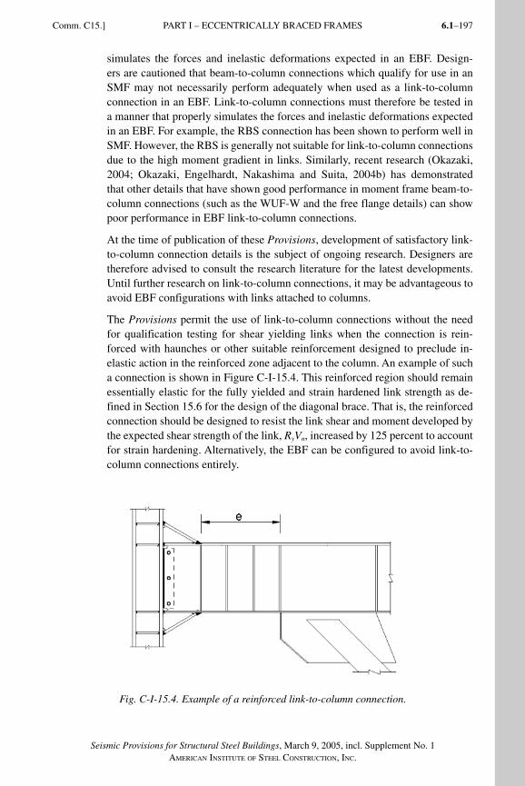
6.1–197
Seismic Provisions for Structural Steel Buildings, March 9, 2005, incl. Supplement No. 1AMERICAN INSTITUTE OF STEEL CONSTRUCTION, INC.
simulates the forces and inelastic deformations expected in an EBF. Design-ers are cautioned that beam-to-column connections which qualify for use in an SMF may not necessarily perform adequately when used as a link-to-column connection in an EBF. Link-to-column connections must therefore be tested in a manner that properly simulates the forces and inelastic deformations expected in an EBF. For example, the RBS connection has been shown to perform well in SMF. However, the RBS is generally not suitable for link-to-column connections due to the high moment gradient in links. Similarly, recent research (Okazaki, 2004; Okazaki, Engelhardt, Nakashima and Suita, 2004b) has demonstrated that other details that have shown good performance in moment frame beam-to-column connections (such as the WUF-W and the free flange details) can show poor performance in EBF link-to-column connections.
At the time of publication of these Provisions, development of satisfactory link-to-column connection details is the subject of ongoing research. Designers are therefore advised to consult the research literature for the latest developments. Until further research on link-to-column connections, it may be advantageous to avoid EBF configurations with links attached to columns.
The Provisions permit the use of link-to-column connections without the need for qualification testing for shear yielding links when the connection is rein-forced with haunches or other suitable reinforcement designed to preclude in-elastic action in the reinforced zone adjacent to the column. An example of such a connection is shown in Figure C-I-15.4. This reinforced region should remain essentially elastic for the fully yielded and strain hardened link strength as de-fined in Section 15.6 for the design of the diagonal brace. That is, the reinforced connection should be designed to resist the link shear and moment developed by the expected shear strength of the link, RyVn, increased by 125 percent to account for strain hardening. Alternatively, the EBF can be configured to avoid link-to-column connections entirely.
Fig. C-I-15.4. Example of a reinforced link-to-column connection.
Comm. C15.] PART I – ECCENTRICALLY BRACED FRAMES
SeismicProvComm1.indd 197SeismicProvComm1.indd 197 9/8/06 3:13:31 PM9/8/06 3:13:31 PMProcess BlackProcess Black
Seismic Provisions for Structural Steel Buildings, March 9, 2005, incl. Supplement No. 1AMERICAN INSTITUTE OF STEEL CONSTRUCTION, INC.
6.1–198
The Provisions do not explicitly address the column panel zone design require-ments at link-to-column connections. Based on limited research (Okazaki, 2004) it is recommended that the panel zone of link-to-column connections be designed in a manner similar to that for SMF beam-to-column connections (Section 9.3) with the required shear strength of the panel zone determined from the link end moments given by the equations in Commentary Section C15.6.
C15.5. Lat eral Bracing of LinkLateral restraint against out-of-plane displacement and twist is required at the ends of the link to ensure stable inel astic beha vior. This section specifies the required strength and stiffness of link end lateral bracing. In typical applications, a composite deck can likely be counted upon to provide adequate lateral bracing at the top flange of the link. However, a composite deck alone cannot be counted on to provide adequate lateral bracing at the bottom flange of the link and direct bracing through transverse beams or a suitable alternative is recommended.
C15.6. Diagonal Brace and Beam Outside of LinksThis section addresses design requirements for the diagonal brace and the beam segment outside of the link in EBF. The intent of these provisions is to ensure that yielding and energy dissipation in an EBF occur primarily in the links. Con-sequently, the diagonal brace and beam segment outside of the link must be designed to resist the loads developed by the fully yielded and strain-hardened link. That is, the brace and beam should be designed following capacity design principles to develop the full inelastic capacity of the links. Limited yielding out-side of the links, particularly in the beams, is sometimes unavoidable in an EBF. Such yielding is likely not detrimental to the performance of the EBF, as long as the beam and brace have sufficient strength to develop the link’s full inelastic strength and deformation capacity.
In most EBF configurations, the diagonal brace and the beam are subject to large axial loads combined with significant bending moments. Consequently, both the diagonal brace and the beam should be designed as beam-columns.
A diagonal brace in a concentrically braced frame is subject to cyclic buckling and is the primary source of energy dissipation in such a frame. Many of the de-sign provisions for OCBF and SCBF systems are intended to permit stable cyclic buckling behavior of the diagonal braces. A properly designed diagonal brace in an EBF, on the other hand, should not buckle, regardless of the intensity of the earthquake ground motion. As long as the brace is designed to be stronger than the link, as is the intent of these provisions, then the link will serve as a fuse to limit the maximum load transferred to the brace, thereby precluding the possi-bility of brace buckling. Consequently, many of the design provisions for braces in OCBF and SCBF systems intended to permit stable cyclic buckling of braces are not needed in EBF. Similarly, the link also limits the loads transferred to the beam beyond the link, thereby precluding failure of this portion of the beam if it is stronger than the link.
PART I – ECCENTRICALLY BRACED FRAMES [Comm. C15.
SeismicProvComm1.indd 198SeismicProvComm1.indd 198 9/8/06 3:13:32 PM9/8/06 3:13:32 PMProcess BlackProcess Black
6.1–199
Seismic Provisions for Structural Steel Buildings, March 9, 2005, incl. Supplement No. 1AMERICAN INSTITUTE OF STEEL CONSTRUCTION, INC.
The diagonal brace and beam segment outside of the link must be designed for some reasonable estimate of the maximum forces that can be developed by the fully yielded and strain hardened link. For this purpose, the nominal shear strength of the link, Vn, as defined by Equation C15-1 is increased by two factors. First, the nominal shear strength is increased by Ry to account for the possibility that the link material may have actual yield strength in excess of the specified minimum value. Secondly, the resulting expected shear strength of the link, RyVn is further increased to account for strain hardening in the link.
Experiments have shown that links can exhibit a high degree of strain harden-ing. Recent tests on rolled wide-flange links constructed of ASTM A992 steel (Arce, 2002) showed strength increases due to strain hardening ranging from 1.2 to 1.45, with an average value of about 1.30. Past tests on rolled wide-flange links constructed of ASTM A36 steel have sometimes shown strength increases due to strain hardening in excess of 1.5 (Hjelmstad and Popov, 1983; Engelhardt and Popov, 1989a). Further, recent tests on very large welded built-up wide-flange links for use in major bridge structures have shown strain hardening fac-tors close to 2.0 (McDaniel, Uang and Seible, 2002; Dusicka and Itani, 2002). These sections, however, typically have proportions significantly different from rolled shapes.
Past researchers have generally recommended a factor of 1.5 (Popov and En-gelhardt, 1988) to account for expected link strength and its strain hardening in the design of the diagonal brace and beam outside of the link. However, for pur-poses of designing the diagonal brace, these provisions have adopted a strength increase due to strain hardening only equal to 1.25. This factor was chosen to be less than 1.5 for a number of reasons, including the use of the Ry factor to account for expected material strength in the link but not in the brace, and the use of resis-tance factors or safety factors when computing the strength of the brace. Further, this value is close to but somewhat below the average measured strain hardening factor for recent tests on rolled wide-flange links of ASTM A992/A992M steel. Designers should recognize that strain hardening in links may sometimes exceed this value, and so a conservative design of the diagonal brace is appropriate. Fur-ther, if large built-up link sections are used with very thick flanges and very short lengths (e < Mp /Vp), designers should consider the possibility of strain hardening factors substantially in excess of 1.25 (Richards, 2004).
Based on the above, the required strength of the diagonal brace can be taken as the forces developed by the following values of link shear and link end moment:
For e ≤ 2Mp/Vp:Link shear = 1.25 RyVp
Link end moment = e (1.25 RyVp)/2
For e > 2Mp/Vp:Link shear = 2(1.25 RyMp)/eLink end moment = 1.25 RyMp
Comm. C15.] PART I – ECCENTRICALLY BRACED FRAMES
SeismicProvComm1.indd 199SeismicProvComm1.indd 199 9/8/06 3:13:32 PM9/8/06 3:13:32 PMProcess BlackProcess Black
Seismic Provisions for Structural Steel Buildings, March 9, 2005, incl. Supplement No. 1AMERICAN INSTITUTE OF STEEL CONSTRUCTION, INC.
6.1–200
The above equations assume link end moments will equalize as the link yields and deforms plastically. For link lengths less than 1.6Mp /Vp attached to columns, link end moments do not fully equalize (Kasai and Popov, 1986a). For this situ-ation, the link ultimate forces can be estimated as follows:
For links attached to columns with e ≤ 1.6 Mp/Vp:Link shear = 1.25 RyVp
Link end moment at column = RyMp
Link end moment at brace = [e(1.25 RyVp) – RyMp] ≥ 0.75 RyMp
The link shear force will generate axial force in the diagonal brace and, for most EBF configurations, will also generate substantial axial force in the beam seg-ment outside of the link. The ratio of beam or brace axial force to link shear force is controlled primarily by the geometry of the EBF and is therefore not affected by inelastic activity within the EBF (Engelhardt and Popov, 1989a). Consequently, this ratio can be determined from an elastic frame analysis and can be used to amplify the beam and brace axial forces to a level that corre-sponds to the link shear force speci fied in the above equations. Further, as long as the beam and brace are designed to remain essentially elastic, the distribution of link end moment to the beam and brace can be estimated from an elastic frame analysis. For example, if an elastic analysis of the EBF under lateral load shows that 80 percent of the link end moment is resisted by the beam and the remaining 20 percent is resisted by the brace, the ultimate link end moments given by the above equations can be distributed to the beam and brace in the same propor-tions. Alternatively, an inelastic frame analysis can be conducted for a more ac-curate estimate of how link end moment is distributed to the beam and brace in the inelastic range.
As described above, these Provisions assume that as a link deforms to large plastic rotations, the link expected shear strength will increase by a factor of 1.25 due to strain hardening. However, for the design of the beam segment outside of the link, the Provisions permit calculation of the beam required strength based on link ultimate forces equal to only 1.1 times the link expected shear strength. This relaxation on link ultimate forces for purposes of designing the beam seg-ment reflects the view that beam strength will be substantially enhanced by the presence of a composite floor slab, and also that limited yielding in the beam will not likely be detrimental to EBF performance, as long as stability of the beam is assured. Consequently, designers should recognize that the actual forces that will develop in the beam will be substantially greater than computed using this 1.1 factor, but this low value of required beam strength will be mitigated by contributions of the floor slab in resisting axial load and bending moment in the beam and by limited yielding in the beam. Based on this approach, the required axial and flexural strength of the beam can be first computed as described above for the diagonal brace, assuming a strain hardening factor of 1.25. The resulting axial force and bending moment in the beam can then be reduced by a factor of 1.1/1.25 = 0.88. In cases where no composite slab is present, designers should consider computing required beam strength based on a link strain hardening factor of 1.25.
PART I – ECCENTRICALLY BRACED FRAMES [Comm. C15.
SeismicProvComm1.indd 200SeismicProvComm1.indd 200 9/8/06 3:13:32 PM9/8/06 3:13:32 PMProcess BlackProcess Black
6.1–201
Seismic Provisions for Structural Steel Buildings, March 9, 2005, incl. Supplement No. 1AMERICAN INSTITUTE OF STEEL CONSTRUCTION, INC.
For most EBF configurations, the beam and the link are a single continuous wide flange member. If this is the case, the available strength of the beam can be increased by Ry. If the link and the beam are the same member, any increase in yield strength present in the link will also be present in the beam segment outside of the link.
Design of the beam segment outside of the link can sometimes be problematic in EBF. In some cases, the beam segment outside of the link is inadequate to resist the required strength based on the link ultimate forces. For such cases, increasing the size of the beam may not provide a solution. This is because the beam and the link are typically the same member. Increasing the beam size therefore increases the link size, which in turn increases the link ultimate forces and therefore in-creases the beam required strength. The relaxation in beam required strength based on the 1.1 factor on link strength was adopted by the Provisions largely as a result of such problems reported by designers, and by the view that EBF performance would not likely be degraded by such a relaxation due to beneficial effects of the floor slab and limited beam yielding, as discussed above. Design problems with the beam can also be minimized by using shear yielding links (e ≤ 1.6 Mp /Vp) as opposed to longer links. The end moments for shear yielding links will be smaller than for longer links, and consequently less moment will be transferred to the beam. Beam moments can be further reduced by locating the intersection of the brace and beam centerlines inside of the link, as described below. Providing a diagonal brace with a large flexural stiffness so that a larger portion of the link end moment is transferred to the brace and away from the beam can also substantially reduce beam moment. In such cases, the brace must be designed to resist these larger moments. Further, the connection between the brace and the link must be designed as a fully restrained moment resisting con-nection. Test results on several brace connection details subject to axial load and bending moment are reported in (Engelhardt and Popov, 1989a).
Avoiding very shallow angles between the diagonal brace and the beam can also mitigate problems with beam design. As the angle between the diagonal brace and the beam decreases, the axial load developed in the beam increases. Using angles between the diagonal brace and the beam of at least about 40 degrees will often be beneficial in reducing beam required axial strength. Problems with de-sign of the beam segment outside of the link can also be addressed by choosing EBF configurations that minimize axial loads in the beam. An example of such a configuration is illustrated in (Engelhardt and Popov, 1989b).
The required strength of the diagonal brace connections in EBF is the same as the required strength of the diagonal brace. The brace connections in EBF are not required to develop the expected yield strength of the brace in tension, as in the case of SCBF brace connections. This is because the diagonal braces in EBF are designed to remain elastic. Nonetheless, to provide some degree of conservatism in the design of brace connections in EBF, these connections must be designed for a required compressive axial strength based on the buckling capacity of the brace, as given in Section 13.3c.
Comm. C15.] PART I – ECCENTRICALLY BRACED FRAMES
SeismicProvComm1.indd 201SeismicProvComm1.indd 201 9/8/06 3:13:33 PM9/8/06 3:13:33 PMProcess BlackProcess Black
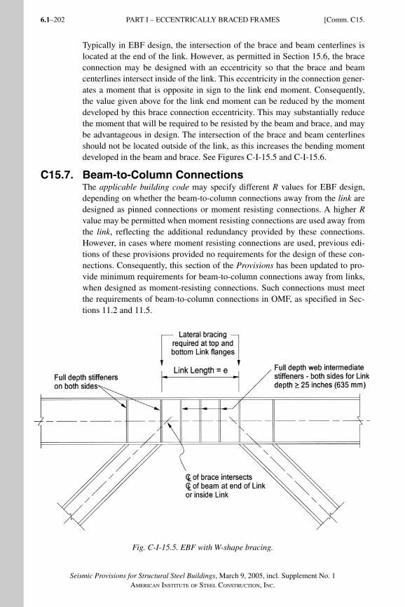
Seismic Provisions for Structural Steel Buildings, March 9, 2005, incl. Supplement No. 1AMERICAN INSTITUTE OF STEEL CONSTRUCTION, INC.
6.1–202
Typically in EBF design, the intersection of the brace and beam centerlines is located at the end of the link. However, as permitted in Section 15.6, the brace connection may be designed with an eccentricity so that the brace and beam center lines intersect inside of the link. This eccentricity in the connection gener-ates a moment that is opposite in sign to the link end moment. Consequently, the value given above for the link end moment can be reduced by the moment developed by this brace connection eccentricity. This may substantially reduce the moment that will be required to be resisted by the beam and brace, and may be advantageous in design. The inter section of the brace and beam centerlines should not be located outside of the link, as this increases the bending moment developed in the beam and brace. See Figures C-I-15.5 and C-I-15.6.
C15.7. Beam-to-Column ConnectionsThe applicable building code may specify different R values for EBF design, depending on whether the beam-to-column connections away from the link are designed as pinned connections or moment resisting connections. A higher R value may be permitted when moment resisting connections are used away from the link, reflecting the additional redundancy provided by these connections. However, in cases where moment resisting connections are used, previous edi-tions of these provisions provided no requirements for the design of these con-nections. Consequently, this section of the Provisions has been updated to pro-vide minimum requirements for beam-to-column connections away from links, when designed as moment-resisting connections. Such connections must meet the requirements of beam-to-column connections in OMF, as specified in Sec-tions 11.2 and 11.5.
Fig. C-I-15.5. EBF with W-shape bracing.
PART I – ECCENTRICALLY BRACED FRAMES [Comm. C15.
SeismicProvComm1.indd 202SeismicProvComm1.indd 202 9/8/06 3:13:33 PM9/8/06 3:13:33 PMProcess BlackProcess Black
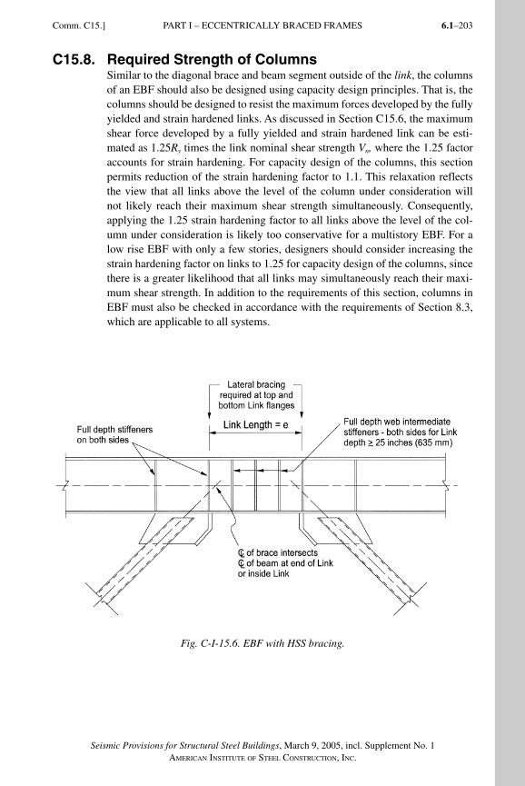
6.1–203
Seismic Provisions for Structural Steel Buildings, March 9, 2005, incl. Supplement No. 1AMERICAN INSTITUTE OF STEEL CONSTRUCTION, INC.
C15.8. Required Strength of ColumnsSimilar to the diagonal brace and beam segment outside of the link, the columns of an EBF should also be designed using capacity design principles. That is, the columns should be designed to resist the maximum forces developed by the fully yielded and strain hardened links. As discussed in Section C15.6, the maximum shear force developed by a fully yielded and strain hardened link can be esti-mated as 1.25Ry times the link nominal shear strength Vn, where the 1.25 factor accounts for strain hardening. For capacity design of the columns, this section permits reduction of the strain hardening factor to 1.1. This relaxation reflects the view that all links above the level of the column under consideration will not likely reach their maximum shear strength simultaneously. Consequently, applying the 1.25 strain hardening factor to all links above the level of the col-umn under consideration is likely too conservative for a multistory EBF. For a low rise EBF with only a few stories, designers should consider increasing the strain hardening factor on links to 1.25 for capacity design of the columns, since there is a greater likelihood that all links may simultaneously reach their maxi-mum shear strength. In addition to the requirements of this section, columns in EBF must also be checked in accordance with the requirements of Section 8.3, which are applicable to all systems.
Fig. C-I-15.6. EBF with HSS bracing.
Comm. C15.] PART I – ECCENTRICALLY BRACED FRAMES
SeismicProvComm1.indd 203SeismicProvComm1.indd 203 9/8/06 3:13:33 PM9/8/06 3:13:33 PMProcess BlackProcess Black
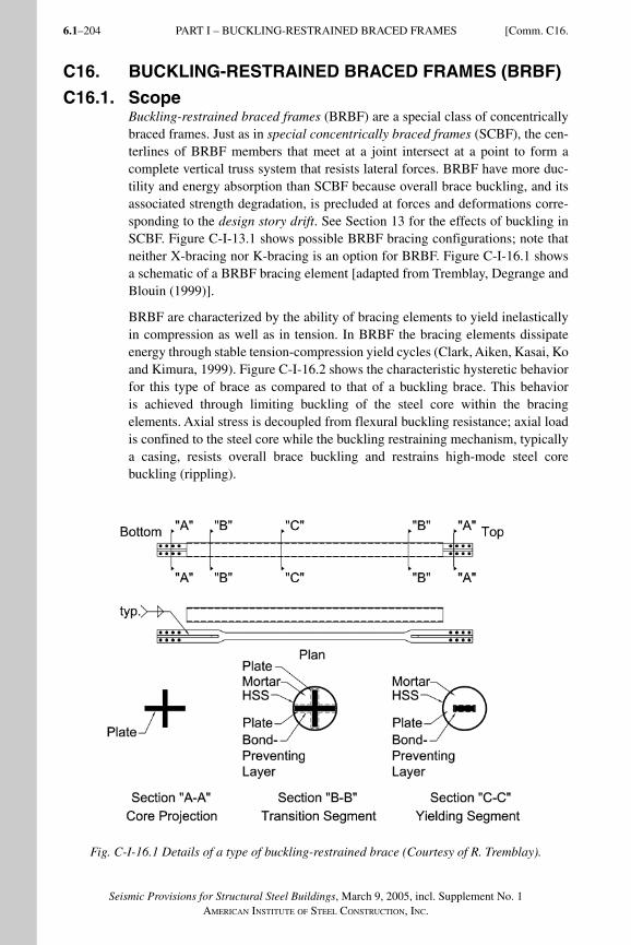
Seismic Provisions for Structural Steel Buildings, March 9, 2005, incl. Supplement No. 1AMERICAN INSTITUTE OF STEEL CONSTRUCTION, INC.
6.1–204
C16. BUCKLING-RESTRAINED BRACED FRAMES (BRBF)
C16.1. ScopeBuckling-restrained braced frames (BRBF) are a special class of concentrically braced frames. Just as in special concentrically braced frames (SCBF), the cen-terlines of BRBF members that meet at a joint intersect at a point to form a complete vertical truss system that resists lateral forces. BRBF have more duc-tility and energy absorption than SCBF because overall brace buckling, and its associated strength degradation, is precluded at forces and deformations corre-sponding to the design story drift. See Section 13 for the effects of buckling in SCBF. Figure C-I-13.1 shows possible BRBF bracing configurations; note that neither X-bracing nor K-bracing is an option for BRBF. Figure C-I-16.1 shows a schematic of a BRBF bracing element [adapted from Tremblay, Degrange and Blouin (1999)].
BRBF are characterized by the ability of bracing elements to yield inelastically in compression as well as in tension. In BRBF the bracing elements dissipate energy through stable tension-compression yield cycles (Clark, Aiken, Kasai, Ko and Kimura, 1999). Figure C-I-16.2 shows the characteristic hysteretic behavior for this type of brace as compared to that of a buckling brace. This behavior is achieved through limiting buckling of the steel core within the bracing elements. Axial stress is decoupled from flexural buckling resistance; axial load is confined to the steel core while the buckling restraining mechanism, typically a casing, resists overall brace buckling and restrains high-mode steel core buckling (rippling).
Fig. C-I-16.1 Details of a type of buckling-restrained brace (Courtesy of R. Tremblay).
PART I – BUCKLING-RESTRAINED BRACED FRAMES [Comm. C16.
SeismicProvComm1.indd 204SeismicProvComm1.indd 204 9/8/06 3:13:34 PM9/8/06 3:13:34 PMProcess BlackProcess Black
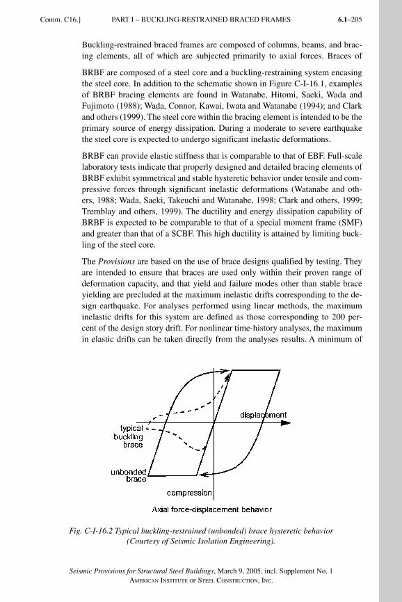
6.1–205
Seismic Provisions for Structural Steel Buildings, March 9, 2005, incl. Supplement No. 1AMERICAN INSTITUTE OF STEEL CONSTRUCTION, INC.
Comm. C16.] PART I – BUCKLING-RESTRAINED BRACED FRAMES
Buckling-restrained braced frames are composed of columns, beams, and brac-ing elements, all of which are subjected primarily to axial forces. Braces of
BRBF are composed of a steel core and a buckling-restraining system encasing the steel core. In addition to the schematic shown in Figure C-I-16.1, examples of BRBF bracing elements are found in Watanabe, Hitomi, Saeki, Wada and Fujimoto (1988); Wada, Connor, Kawai, Iwata and Watanabe (1994); and Clark and others (1999). The steel core within the bracing element is intended to be the primary source of energy dissipation. During a moderate to severe earthquake the steel core is expected to undergo significant inelastic deformations.
BRBF can provide elastic stiffness that is comparable to that of EBF. Full-scale laboratory tests indicate that properly designed and detailed bracing elements of BRBF exhibit symmetrical and stable hysteretic behavior under tensile and com-pressive forces through significant inelastic deformations (Watanabe and oth-ers, 1988; Wada, Saeki, Takeuchi and Watanabe, 1998; Clark and others, 1999; Tremblay and others, 1999). The ductility and energy dissipation capability of BRBF is expected to be comparable to that of a special moment frame (SMF) and greater than that of a SCBF. This high ductility is attained by limiting buck-ling of the steel core.
The Provisions are based on the use of brace designs qualified by testing. They are intended to ensure that braces are used only within their proven range of deformation capacity, and that yield and failure modes other than stable brace yielding are precluded at the maximum inelastic drifts corresponding to the de-sign earthquake. For analyses performed using linear methods, the maximum inelastic drifts for this system are defined as those corresponding to 200 per-cent of the design story drift. For nonlinear time-history analyses, the maximum in elastic drifts can be taken directly from the analyses results. A minimum of
Fig. C-I-16.2 Typical buckling-restrained (unbonded) brace hysteretic behavior (Courtesy of Seismic Isolation Engineering).
SeismicProvComm1.indd 205SeismicProvComm1.indd 205 9/8/06 3:13:35 PM9/8/06 3:13:35 PMProcess BlackProcess Black
Seismic Provisions for Structural Steel Buildings, March 9, 2005, incl. Supplement No. 1AMERICAN INSTITUTE OF STEEL CONSTRUCTION, INC.
6.1–206
2 percent story drift is required for determining expected brace deformations for testing (see Appendix T) and is recommended for detailing. This approach is consistent with the linear analysis equations for design story drift in SEI/ASCE 7 (ASCE, 2002) and the 2003 NEHRP Recommended Provisions (FEMA, 2003). It is also noted that the consequences of loss of connection stability due to the actual seismic displacements exceeding the calculated values may be severe; braces are therefore required to have a larger deformation capacity than directly indicated by linear static analysis.
The value of 200 percent of the design story drift for expected brace deforma-tions represents the mean of the maximum story response for ground motions having a 10 percent chance of exceedance in 50 years (Fahnestock, Sause and Ricles, 2003; Sabelli and others, 2003). Near-fault ground motions, as well as stronger ground motions, can impose deformation demands on braces larger than those required by these provisions. Detailing and testing braces for larger defor-mations will provide higher reliability and better performance.
Although this system has not been included in SEI/ASCE 7 (ASCE, 2002), the Provisions have been written assuming that future editions of SEI/ASCE 7 and of national codes will define system coefficients and limits for BRBF. The assumed values for the response modification coefficient, system over strength factor, and deflection amplification factor are given in Appendix R, as are height limits and period-calculation coefficients.
The design engineer utilizing these provisions is strongly encouraged to consider the effects of configuration and proportioning of braces on the potential forma-tion of building yield mechanisms. The axial yield strength of the core, Pysc, can be set precisely with final core cross-sectional area determined by dividing the specified brace capacity by actual material yield strength established by coupon testing, multiplied by the resistance factor. In some cases, cross-sectional area will be governed by brace stiffness requirements to limit drift. In either case, careful proportioning of braces can make yielding distributed over the building height much more likely than in conventional braced frames.
It is also recommended that engineers refer to the following documents to gain further understanding of this system: Uang and Nakashima (2003); Watanabe and others (1988); Reina and Normile (1997); Clark and others (1999); Trem-blay and others (1999); and Kalyanaraman, Sridhara and Thairani (1998) to gain further understanding of this system.
The design provisions for BRBF are predicated on reliable brace performance. In order to assure this performance, a quality assurance plan is required. These measures are in addition to those covered in the AISC Code of Standard Practice (AISC, 2005b) and Section 16 of the 2002 Seismic Provisions for Structural Steel Buildings. Examples of measures that may provide quality assurance are:
(1) Special inspection of brace fabrication. Inspection may include confirma-tion of fabrication and alignment tolerances, as well as NDT methods for evaluation of the final product.
PART I – BUCKLING-RESTRAINED BRACED FRAMES [Comm. C16.
SeismicProvComm1.indd 206SeismicProvComm1.indd 206 9/8/06 3:13:36 PM9/8/06 3:13:36 PMProcess BlackProcess Black
6.1–207
Seismic Provisions for Structural Steel Buildings, March 9, 2005, incl. Supplement No. 1AMERICAN INSTITUTE OF STEEL CONSTRUCTION, INC.
(2) Brace manufacturer’s participation in a recognized quality certification program.
(3) Certification should include documentation that the manufacturer’s Quality Assurance Plan is in compliance with the requirements of the BRBF provi-sions, the Seismic Provisions for Structural Steel Buildings, and the Code of Standard Practice. The manufacturing and quality control procedures should be equivalent to, or better, than those used to manufacture brace test specimens.
C16.2. Bracing Members
C16.2a. Steel CoreThe steel core is composed of a yielding segment and steel core projections; it may also contain transition segments between the projections and yielding segment. The cross-sectional area of the yielding segment of the steel core is expected to be sized so that its yield strength is fairly close to the demand calcu-lated from the applicable building code. Designing braces close to the required strengths will help ensure distribution of yielding over multiple stories in the building. Conversely, overdesigning some braces more than others (for example, by using the same size brace on all floors) may result in an undesirable concen-tration of inelastic deformations in only a few stories. The length and area of the yielding segment, in conjunction with the lengths and areas of the nonyielding segments, determine the stiffness of the brace. The yielding segment length and brace inclination also determines the strain demand corresponding to the design story drift.
In typical brace designs, a projection of the steel core beyond its casing is nec-essary in order to accomplish a connection to the frame. Buckling of this unre-strained zone is an undesirable failure mode and must therefore be precluded.
In typical practice, the designer specifies the core plate dimensions as well as the steel material and grade. The steel stress-strain characteristics may vary signifi-cantly within the range permitted by the steel specification, potentially resulting in significant brace overstrength. This overstrength must be addressed in the design of connections as well as of frame beams and columns. The designer may specify a limited range of acceptable yield stress in order to more strictly define the permissible range of brace capacity. Alternatively, the designer may specify a limited range of acceptable yield stress if this approach is followed in order to more strictly define the permissible range of core plate area (and the resulting brace stiffness). The brace supplier may then select the final core plate dimensions to meet the capacity requirement using the results of a coupon test. The designer should be aware that this approach may result in a deviation from the calculated brace axial stiffness. The maximum magnitude of the deviation is dependent on the range of acceptable material yield stress. Designers following this approach should consider the possible range of stiffness in the building anal-ysis in order to adequately address both the building period and expected drift.
Comm. C16.] PART I – BUCKLING-RESTRAINED BRACED FRAMES
SeismicProvComm1.indd 207SeismicProvComm1.indd 207 9/8/06 3:13:36 PM9/8/06 3:13:36 PMProcess BlackProcess Black
Seismic Provisions for Structural Steel Buildings, March 9, 2005, incl. Supplement No. 1AMERICAN INSTITUTE OF STEEL CONSTRUCTION, INC.
6.1–208
The strength of the steel core has been defined in terms of a new symbol, Fysc, which is defined as either the specified minimum yield stress of the steel core, or actual yield stress of the steel core as determined from a coupon test. The use of coupon tests in establishing Fysc eliminates the necessity of using the factor Ry in calculating the adjusted brace strength (see Commentary Section C16.2d). This is in recognition of the fact that coupon testing of the steel core material is in effect required by the similitude provisions in Appendix T, and such coupon tests can provide a more reliable estimation of expected strength.
C16.2b. Buckling-Restraining System This term describes those elements providing brace stability against overall buckling. This includes the casing as well as elements connecting the core. The adequacy of the buckling-restraining system must be demonstrated by testing.
C16.2c. TestingTesting of braces is considered necessary for this system. The applicability of tests to the designed brace is defined in Appendix T. Commentary Section C9.2a, which describes in general terms the applicability of tests to designs, applies to BRBF.
BRBF designs require reference to successful tests of a similarly sized test speci-men and of a brace subassemblage that includes rotational demands. The former is a uniaxial test intended to demonstrate adequate brace hysteretic behavior. The latter is intended to verify the general brace design concept and demonstrate that the rotations associated with frame deformations do not cause failure of the steel core projection, binding of the steel core to the casing, or otherwise compromise the brace hysteretic behavior. A single test may qualify as both a subassemblage and a brace test subject to the requirements of Appendix T; for certain frame-type subassemblage tests, obtaining brace axial forces may prove difficult and separate brace tests may be necessary. A sample subassemblage test is shown in Figure C-I-T.1 (Tremblay and others, 1999).
During the planning stages of either a subassemblage or uniaxial brace test, cer-tain conditions may exist that cause the test specimen to deviate from the param-eters established in the testing appendix. These conditions may include
(1) Lack of availability of beam, column, and brace sizes that reasonably match those to be used in the actual building frame
(2) Test set-up limitations in the laboratory
(3) Transportation and field-erection constraints
(4) Actuator to subassemblage connection conditions that require reinforce-ment of test specimen elements not reinforced in the actual building frame
In certain cases, both the authority having jurisdiction and the peer reviewer may deem such deviations acceptable. The cases in which such deviations are accept-able are project-specific by nature and, therefore, do not lend themselves to fur-ther description in this Commentary. For these specific cases, it is recommended that the engineer of record demonstrate that the following objectives are met:
PART I – BUCKLING-RESTRAINED BRACED FRAMES [Comm. C16.
SeismicProvComm1.indd 208SeismicProvComm1.indd 208 9/8/06 3:13:36 PM9/8/06 3:13:36 PMProcess BlackProcess Black
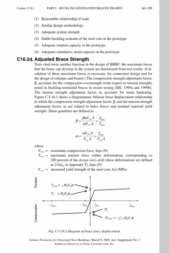
6.1–209
Seismic Provisions for Structural Steel Buildings, March 9, 2005, incl. Supplement No. 1AMERICAN INSTITUTE OF STEEL CONSTRUCTION, INC.
(1) Reasonable relationship of scale
(2) Similar design methodology
(3) Adequate system strength
(4) Stable buckling-restraint of the steel core in the prototype
(5) Adequate rotation capacity in the prototype
(6) Adequate cumulative strain capacity in the prototype
C16.2d. Adjusted Brace StrengthTests cited serve another function in the design of BRBF: the maximum forces that the brace can develop in the system are determined from test results. (Cal-culation of these maximum forces is necessary for connection design and for the design of columns and beams.) The compression-strength adjustment factor, β, accounts for the compression overstrength (with respect to tension strength) noted in buckling-restrained braces in recent testing (SIE, 1999a and 1999b). The tension strength adjustment factor, ω, accounts for strain hardening. Figure C-I-16.3 shows a diagrammatic bilinear force-displacement relationship in which the compression strength adjustment factor, β, and the tension-strength adjustment factor, ω, are related to brace forces and nominal material yield strength. These quantities are defined as
ββωω
= =F A
F A
P
T
ysc
ysc
max
max
ω
ω= =
F A
F A
T
F A
ysc
ysc
max
ysc
wherePmax = maximum compression force, kips (N)Tmax = maximum tension force within deformations corresponding to
200 percent of the design story drift (these deformations are defined as 2.0Δbm in Appendix T), kips (N)
Fysc = measured yield strength of the steel core, ksi (MPa)
Fig. C-I-16.3.Diagram of brace force displacement.
Comm. C16.] PART I – BUCKLING-RESTRAINED BRACED FRAMES
SeismicProvComm1.indd 209SeismicProvComm1.indd 209 9/8/06 3:13:36 PM9/8/06 3:13:36 PMProcess BlackProcess Black
Seismic Provisions for Structural Steel Buildings, March 9, 2005, incl. Supplement No. 1AMERICAN INSTITUTE OF STEEL CONSTRUCTION, INC.
6.1–210
Note that the specified minimum yield stress of the steel core, Fy, is not typically used for establishing these factors; instead, Fysc is used which is determined by the coupon tests required to demonstrate compliance with Appendix T. Braces with values of β and ω less than unity are not true buckling-restrained braces and their use is precluded by the provisions.
The expected brace strengths, used in the design of connections and of beams and columns, are adjusted upwards for various sources of overstrength, includ-ing amplification due to expected material strength (using the ratio Ry) and the strain hardening, ω, and compression adjustment, β, factors discussed above. The amplification due to expected material strength can be eliminated if the brace yield stress is determined by a coupon test and is used to size the steel core area to provide the desired available strength precisely. Other sources of over-strength, such as imprecision in the provision of the steel core area, may need to be considered; fabrication tolerance for the steel core is typically negligible.
C16.3. Bracing ConnectionsBracing connections must not yield at force levels corresponding to the yielding of the steel core; they are therefore designed for the maximum force that can be expected from the brace (see Section C16.2b). In addition, a factor of 1.1 is used. This factor is applied in consideration of the possibility of braces being subjected to deformations exceeding those at which the factors ω and β are required to be determined (in other words, 200 percent of the Δbm; see Section C16.2b.).
The engineer should recognize that the bolts are likely to slip at forces 30 percent lower than their design strength. This slippage is not considered to be detrimen-tal to behavior of the BRBF system and is consistent with the design approach found in Section 7.2. See also commentary in Section C7.2. Bolt holes may be drilled or punched subject to the requirements of Section M2.5 of the Specifica-tion for Structural Steel Buildings (AISC, 2005).
Recent testing in stability and fracture (Tsai, Weng, Lin, Chen, Lai and Hsiao, 2003) has demonstrated that gusset-plate connections may be a critical aspect of the design of BRBF (Tsai and others, 2003; Lopez, Gwie, Lauck and Saunders, 2004). The tendency to instability may vary depending on the flexural stiffness of the connection portions of the buckling restrained brace and the degree of their flexural continuity with the casing. This aspect of BRBF design is the sub-ject of continuing investigation and designers are encouraged to consult research publications as they become available. The stability of gussets may be demon-strated by testing, if the test specimen adequately resembles the conditions in the building. It is worth noting that during an earthquake the frame may be subjected to some out-of-plane displacement concurrent with the in-plane deformations, so a degree of conservatism in the design of gussets may be warranted.
PART I – BUCKLING-RESTRAINED BRACED FRAMES [Comm. C16.
SeismicProvComm1.indd 210SeismicProvComm1.indd 210 9/8/06 3:13:37 PM9/8/06 3:13:37 PMProcess BlackProcess Black
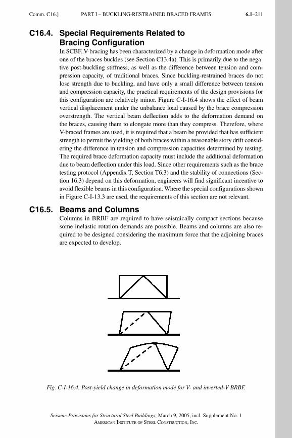
6.1–211
Seismic Provisions for Structural Steel Buildings, March 9, 2005, incl. Supplement No. 1AMERICAN INSTITUTE OF STEEL CONSTRUCTION, INC.
C16.4. Special Requirements Related to Bracing Configuration In SCBF, V-bracing has been characterized by a change in deformation mode after one of the braces buckles (see Section C13.4a). This is primarily due to the nega-tive post-buckling stiffness, as well as the difference between tension and com-pression capacity, of traditional braces. Since buckling-restrained braces do not lose strength due to buckling, and have only a small difference between tension and compression capacity, the practical requirements of the design provisions for this configuration are relatively minor. Figure C-I-16.4 shows the effect of beam vertical displacement under the unbalance load caused by the brace compression overstrength. The vertical beam deflection adds to the deformation demand on the braces, causing them to elongate more than they compress. Therefore, where V-braced frames are used, it is required that a beam be provided that has sufficient strength to permit the yielding of both braces within a reasonable story drift consid-ering the difference in tension and compression capacities determined by testing. The required brace deformation capacity must include the additional deformation due to beam deflection under this load. Since other requirements such as the brace testing protocol (Appendix T, Section T6.3) and the stability of connections (Sec-tion 16.3) depend on this deformation, engineers will find significant incentive to avoid flexible beams in this configuration. Where the special configurations shown in Figure C-I-13.3 are used, the requirements of this section are not relevant.
C16.5. Beams and ColumnsColumns in BRBF are required to have seismically compact sections because some inelastic rotation demands are possible. Beams and columns are also re-quired to be designed considering the maximum force that the adjoining braces are expected to develop.
Fig. C-I-16.4. Post-yield change in deformation mode for V- and inverted-V BRBF.
Comm. C16.] PART I – BUCKLING-RESTRAINED BRACED FRAMES
SeismicProvComm1.indd 211SeismicProvComm1.indd 211 9/8/06 3:13:37 PM9/8/06 3:13:37 PMProcess BlackProcess Black
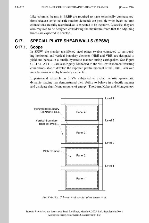
Seismic Provisions for Structural Steel Buildings, March 9, 2005, incl. Supplement No. 1AMERICAN INSTITUTE OF STEEL CONSTRUCTION, INC.
6.1–212
Like columns, beams in BRBF are required to have seismically compact sec-tions because some inelastic rotation demands are possible when beam-column connections are fully restrained, as is expected to be the norm. Likewise, they are also required to be designed considering the maximum force that the adjoining braces are expected to develop.
C17. SPECIAL PLATE SHEAR WALLS (SPSW)
C17.1. ScopeIn SPSW, the slender unstiffened steel plates (webs) connected to surround-ing horizontal and vertical boundary elements (HBE and VBE) are designed to yield and behave in a ductile hysteretic manner during earthquakes. See Figure C-I-17-1. All HBE are also rigidly connected to the VBE with moment resisting connections able to develop the expected plastic moment of the HBE. Each web must be surrounded by boundary elements.
Experimental research on SPSW subjected to cyclic inelastic quasi-static dynamic loading has demonstrated their ability to behave in a ductile manner and dissipate significant amounts of energy (Thorburn, Kulak and Montgomery,
Fig. C-I-17.1. Schematic of special plate shear wall.
PART I – BUCKLING-RESTRAINED BRACED FRAMES [Comm. C16.
SeismicProvComm1.indd 212SeismicProvComm1.indd 212 9/8/06 3:13:38 PM9/8/06 3:13:38 PMProcess BlackProcess Black
6.1–213
Seismic Provisions for Structural Steel Buildings, March 9, 2005, incl. Supplement No. 1AMERICAN INSTITUTE OF STEEL CONSTRUCTION, INC.
Comm. C17.] PART I – SPECIAL PLATE SHEAR WALLS
1983; Timler and Kulak, 1983; Tromposch and Kulak, 1987; Roberts and Sabouri-Ghomi, 1992; Caccese, Elgaaly and Chen, 1993; Driver, Kulak, Kennedy and Elwi, 1997; Elgaaly, 1998; Rezai, 1999; Lubell, Prion, Ventura and Rezai, 2000; Berman and Bruneau, 2003a). This has been confirmed by analytical studies using finite element analysis and other analysis techniques (Sabouri-Ghomi and Roberts, 1992; Elgaaly, Caccese and Du, 1993; Elgaaly and Liu, 1997; Driver and others, 1997).
Yielding of the webs occurs by development of tension field action at an angle close to 45° from the vertical, and buckling of the plate in the orthogonal direc-tion. Past research shows that the sizing of VBE and HBE in a SPSW makes it possible to develop this tension field action across the entire webs. Except for cases with very stiff HBE and VBE, yielding in the webs develops in a progres-sive manner across each panel. Because the webs do not yield in compression, continued yielding upon repeated cycles of loading is contingent upon the SPSW being subjected to progressively larger drifts, except for the contribution of plas-tic hinging developing in the HBE to the total system hysteretic energy. In past research (Driver and others, 1997), the yielding of boundary elements contrib-uted approximately 25 to 30 percent of the total load strength of the system.
With the exception of plastic hinging at the ends of HBE, the surrounding horizon-tal and vertical boundary elements are designed to remain essentially elastic when the webs are fully yielded. Plastic hinging at the ends of HBE is needed to develop the plastic collapse mechanism of this system. Plastic hinging in the middle of HBE, which could partly prevent yielding of the webs, is deemed undesirable. Cases of both desirable and undesirable yielding in VBE have been observed in past testing. In absence of a theoretical formulation to quantify the conditions lead-ing to acceptable yielding (and supporting experimental validation of this formula-tion), the conservative requirement of elastic VBE response is justified.
Research literature often compares the behavior of steel plate walls to that of a vertical plate girder, indicating that the webs of a SPSW resist shears by tension field action and that the VBE of a SPSW resist overturning moments. While this analogy is useful in providing a conceptual understanding of the behavior of SPSW, many significant differences exist in the behavior and strength of the two systems. Past research shows that the use of structural shapes for the VBE and HBE in SPSW (as well as other dimensions and details germane to SPSW) favorably impacts orientation of the angle of development of the tension field action, and makes possible the use of very slender webs (having negligible di-agonal compressive strength). Sizeable top and bottom HBE are also required in SPSW to anchor the significant tension fields that develop at these ends of the structural system. Limits imposed on the maximum web slenderness of plate girders to prevent flange buckling, or due to transportation requirements, are also not applicable to SPSW which are constructed differently. For these reasons, the use of beam design provisions in the Specification (AISC, 2005) for the design of SPSW is not appropriate (Berman and Bruneau, 2004).
SeismicProvComm1.indd 213SeismicProvComm1.indd 213 9/8/06 3:13:39 PM9/8/06 3:13:39 PMProcess BlackProcess Black
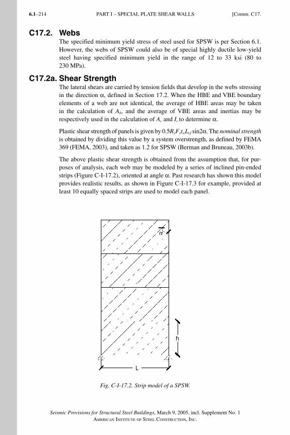
Seismic Provisions for Structural Steel Buildings, March 9, 2005, incl. Supplement No. 1AMERICAN INSTITUTE OF STEEL CONSTRUCTION, INC.
6.1–214
C17.2. WebsThe specified minimum yield stress of steel used for SPSW is per Section 6.1. However, the webs of SPSW could also be of special highly ductile low-yield steel having specified minimum yield in the range of 12 to 33 ksi (80 to 230 MPa).
C17.2a. Shear StrengthThe lateral shears are carried by tension fields that develop in the webs stressing in the direction α, defined in Section 17.2. When the HBE and VBE boundary elements of a web are not identical, the average of HBE areas may be taken in the calculation of Ab, and the average of VBE areas and inertias may be respectively used in the calculation of Ac and Ic to determine α.
Plastic shear strength of panels is given by 0.5RyFytwLcf sin2α. The nominal strength is obtained by dividing this value by a system overstrength, as defined by FEMA 369 (FEMA, 2003), and taken as 1.2 for SPSW (Berman and Bruneau, 2003b).
The above plastic shear strength is obtained from the assumption that, for pur-poses of analysis, each web may be modeled by a series of inclined pin-ended strips (Figure C-I-17.2), oriented at angle α. Past research has shown this model provides realistic results, as shown in Figure C-I-17.3 for example, provided at least 10 equally spaced strips are used to model each panel.
Fig. C-I-17.2. Strip model of a SPSW.
PART I – SPECIAL PLATE SHEAR WALLS [Comm. C17.
SeismicProvComm1.indd 214SeismicProvComm1.indd 214 9/8/06 3:13:40 PM9/8/06 3:13:40 PMProcess BlackProcess Black
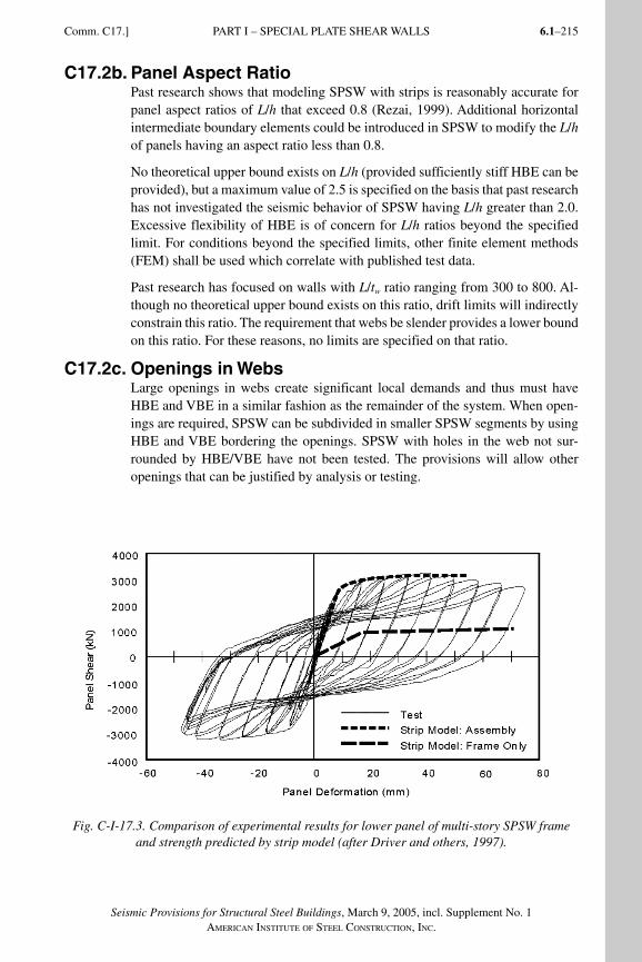
6.1–215
Seismic Provisions for Structural Steel Buildings, March 9, 2005, incl. Supplement No. 1AMERICAN INSTITUTE OF STEEL CONSTRUCTION, INC.
C17.2b. Panel Aspect RatioPast research shows that modeling SPSW with strips is reasonably accurate for panel aspect ratios of L/h that exceed 0.8 (Rezai, 1999). Additional horizontal intermediate boundary elements could be introduced in SPSW to modify the L/h of panels having an aspect ratio less than 0.8.
No theoretical upper bound exists on L/h (provided sufficiently stiff HBE can be provided), but a maximum value of 2.5 is specified on the basis that past research has not investigated the seismic behavior of SPSW having L/h greater than 2.0. Excessive flexibility of HBE is of concern for L/h ratios beyond the specified limit. For conditions beyond the specified limits, other finite element methods (FEM) shall be used which correlate with published test data.
Past research has focused on walls with L/tw ratio ranging from 300 to 800. Al-though no theoretical upper bound exists on this ratio, drift limits will indirectly constrain this ratio. The requirement that webs be slender provides a lower bound on this ratio. For these reasons, no limits are specified on that ratio.
C17.2c. Openings in WebsLarge openings in webs create significant local demands and thus must have HBE and VBE in a similar fashion as the remainder of the system. When open-ings are required, SPSW can be subdivided in smaller SPSW segments by using HBE and VBE bordering the openings. SPSW with holes in the web not sur-rounded by HBE/VBE have not been tested. The provisions will allow other openings that can be justified by analysis or testing.
Fig. C-I-17.3. Comparison of experimental results for lower panel of multi-story SPSW frame and strength predicted by strip model (after Driver and others, 1997).
Comm. C17.] PART I – SPECIAL PLATE SHEAR WALLS
SeismicProvComm1.indd 215SeismicProvComm1.indd 215 9/8/06 3:13:40 PM9/8/06 3:13:40 PMProcess BlackProcess Black
Seismic Provisions for Structural Steel Buildings, March 9, 2005, incl. Supplement No. 1AMERICAN INSTITUTE OF STEEL CONSTRUCTION, INC.
6.1–216
C17.3. Connections of Webs to Boundary ElementsThe required strength of web connections to the surrounding HBE and VBE are required to develop the expected tensile strength of the webs. Net sections must also provide this strength for the case of bolted connections.
The strip model can be used to model the behavior of SPSW and the tensile yielding of the webs at angle, α. A single angle of inclination taken as the aver-age for all the panels may be used to analyze the entire wall. The expected tensile strength of the web strips shall be defined as RyFy As, where
As = area of a strip = (L cos α + H sinα)/nL = width of panelH = height of panel n = number of strips per panel and n shall be taken greater than or equal
to 10
This analysis method has been shown, through correlation with physical test data, to adequately predict SPSW performance. It is recognized, however, that other advanced analytical techniques [such as the finite element method (FEM)] may also be used for design of SPSW. If such nonlinear (geometric and material) FEM models are used, they should be calibrated against published test results to ascertain reliability for application. Designs of connections of webs to boundary elements should also anticipate buckling of the web plate. Some minimum out-of-plane rotational restraint of the plate should be provided (Caccese, Elgaaly and Chen, 1993).
C17.4. Horizontal and Vertical Boundary Elements
C17.4a. Required StrengthPer capacity design principles, all edge boundary elements (HBE and VBE) shall be designed to resist the maximum forces developed by the tension field action of the webs fully yielding. Axial forces, shears, and moments develop in the boundary elements of the SPSW as a result of the response of the system to the overall overturning and shear, and this tension field action in the webs. Actual web thickness must be considered for this calculation, because webs thicker than required may have to be used due to availability, or minimum thickness required for welding.
At the top panel of the wall, the vertical components of the tension field shall be anchored to the HBE. The HBE shall have sufficient strength to allow develop-ment of full tensile yielding across the panel width.
At the bottom panel of the wall, the vertical components of the tension field shall be anchored to the HBE. The HBE shall have sufficient strength to allow devel-opment of full tensile yielding across the panel width. This may be accomplished by continuously anchoring the HBE to the foundation.
For intermediate HBE of the wall, the anticipated variation between the top and bottom web normal stresses acting on the HBE is usually small, or null when webs in the panel above and below the HBE have identical thickness. While
PART I – SPECIAL PLATE SHEAR WALLS [Comm. C17.
SeismicProvComm1.indd 216SeismicProvComm1.indd 216 9/8/06 3:13:41 PM9/8/06 3:13:41 PMProcess BlackProcess Black
6.1–217
Seismic Provisions for Structural Steel Buildings, March 9, 2005, incl. Supplement No. 1AMERICAN INSTITUTE OF STEEL CONSTRUCTION, INC.
Comm. C17.] PART I – SPECIAL PLATE SHEAR WALLS
top and bottom HBE are typically of substantial size, intermediate HBE are relatively smaller.
Beyond the exception mentioned in Section 17.1, in some instances, the engineer may be able to justify yielding of the boundary elements by demonstrating that the yielding of this edge boundary element will not cause reduction on the SPSW shear capacity to support the demand and will not cause a failure in vertical grav-ity carrying capacity.
Forces and moments in the members (and connections), including those result-ing from tension field action, may be determined from a plane frame analysis. The web is represented by a series of inclined pin-ended strips, as described in Section C17.3. A minimum of ten equally spaced pin-ended strips per panel will be used in such an analysis.
A number of analytical approaches are possible to achieve capacity design and determine the same forces acting on the vertical boundary elements. Some ex-ample methods applicable to SPSW follow. In all cases, actual web thickness must be considered, for reasons described earlier.
Nonlinear push-over analysis. A model of the SPSW can be constructed in which bilinear elasto-plastic web elements of strength RyFy As are introduced in the direction α. Bilinear plastic hinges can also be introduced at the ends of the horizontal boundary elements. Standard push-over analysis conducted with this model will provide axial forces, shears, and moments in the boundary frame when the webs develop yielding. Separate checks are required to verify that plastic hinges do not develop in the horizontal boundary elements, except at their ends.
Combined linear elastic computer programs and capacity design concept. The following four-step procedure provides reasonable estimates of forces in the boundary elements of SPSW systems.
(1) Lateral forces: Use combined model, boundary elements and web elements, to come up with the demands in the web and the boundary elements based on the code required base shear. The web elements shall not be considered as vertical-load carrying elements.
(2) Gravity load (dead load and live load): Apply gravity loads to a model with only gravity frames. The web elements shall not be considered as vertical-load carrying elements.
(3) Without any overstrength factors, design the boundary elements using the demands based on combination forces of the above steps 1 and 2.
(4) Boundary element capacity design check: Check the boundary element for the maximum capacity of the web elements in combination with the maxi-mum possible axial load due to over-turning moment. Use the axial force obtained from step 1 above and multiply by overstrength factor Ωo. Apply load from web elements (RyFy As) in the direction of α. For this capacity de-sign check use a material strength reduction factor of 1.0. For determination
SeismicProvComm1.indd 217SeismicProvComm1.indd 217 9/8/06 3:13:41 PM9/8/06 3:13:41 PMProcess BlackProcess Black
Seismic Provisions for Structural Steel Buildings, March 9, 2005, incl. Supplement No. 1AMERICAN INSTITUTE OF STEEL CONSTRUCTION, INC.
6.1–218
of the required strength of boundary elements and their connection to the web, neither the resistance factor (LRFD), nor the safety factor (ASD), are applied to the strength of the web.
Indirect capacity design approach. CSA-S16-02 (CSA, 2002) proposes that loads in the vertical boundary members can be determined from the gravity loads combined with the seismic loads increased by the amplification factor,
B = Ve / Vu
whereVe = expected shear strength, at the base of the wall, determined for the
web thickness supplied = 0.5 Ry Fy tw L sin2αVu = factored lateral seismic force at the base of the wall
In determining the loads in VBEs, the amplification factor, B, need not be taken as greater than R.
The VBE design axial forces shall be determined from overturning moments defined as follows:
(1) the moment at the base is BMu, where Mu is the factored seismic overturning moment at the base of the wall corresponding to the force Vu ;
(2) the moment BMu extends for a height H but not less than two stories from the base; and
(3) the moment decreases linearly above a height H to B times the overturning moment at one story below the top of the wall, but need not exceed R times the factored seismic overturning moment at the story under consideration corresponding to the force Vu .
The local bending moments in the VBE due to tension field action in the web shall be multiplied by the amplification factor B.
Preliminary design. For preliminary proportioning of HBE, VBE, and webs, a SPSW wall may be approximated by a vertical truss with tension diagonals. Each web is represented by a single diagonal tension brace within the story. For an assumed angle of inclination of the tension field, the web thickness, tw , may be taken as
2AΩ sinθ
t L sin2αw
s =
whereA = area of the equivalent tension braceθ = angle between the vertical and the longitudinal axis of the equivalent
diagonal braceL = the distance between VBE centerlinesα = assumed angle of inclination of the tension field measured from the
vertical per Section 17.2a
PART I – SPECIAL PLATE SHEAR WALLS [Comm. C17.
SeismicProvComm1.indd 218SeismicProvComm1.indd 218 9/8/06 3:13:41 PM9/8/06 3:13:41 PMProcess BlackProcess Black
6.1–219
Seismic Provisions for Structural Steel Buildings, March 9, 2005, incl. Supplement No. 1AMERICAN INSTITUTE OF STEEL CONSTRUCTION, INC.
Ωs = the system overstrength factor, as defined by FEMA 369, and taken as 1.2 for SPSW (Berman and Bruneau, 2003)
A is initially estimated from an equivalent brace size to meet the structure’s drift requirements.
C17.4c. Width-Thickness LimitationsSome amount of local yielding is expected in the HBE and VBE to allow the development of the plastic mechanism of SPSW systems. For that reason, HBE and VBE shall comply with the requirements in Table I-8-1 for SMF.
C17.4d. Lateral BracingProviding stability of SPSW systems boundary elements is necessary for proper performance of the system. The lateral bracing requirements for HBE are pro-vided to be consistent with beams in SMF for both strength and stiffness. In addition, all intersections of HBE and VBE must be braced to ensure stability of the entire panel.
C17.4f. Panel ZonesPanel zone requirements are not imposed for intermediate HBE. These are ex-pected to be small HBE connecting to sizeable VBE. The engineer should use judgment to identify special situations in which the panel zone adequacy of VBE next to intermediate HBE should be verified.
C17.4g. Stiffness of Vertical Boundary ElementsThis requirement is intended to prevent excessive in-plane flexibility and buck-ling of VBE. Opportunity exists for future research to confirm or improve the applicability of this requirement.
C18. QUALITY ASSURANCE PLANTo assure ductile seismic response, steel framing is required to meet the quality requirements as appropriate for the various components of the structure. The ap-plicable building code may have specific quality assurance plan requirements. SEI/ASCE 7 (ASCE, 2005) provides special requirements for inspection and testing based upon the seismic design category. Additionally, the Provisions, the Specification, the AISC Code of Standard Practice (AISC, 2005b), the AWS D1.1 Structural Welding Code—Steel (AWS, 2004), and the RCSC Specification for Structural Joints Using ASTM A325 or A490 Bolts (RCSC, 2004) provide acceptance criteria for steel building structures. The Provisions require that a quality assurance plan be implemented as required by the applicable building code or the engineer of record.
In some cases, the fabricator implements a quality control system as part of their normal operations, particularly fabricators that participate in AISC Quality Cer-tification or similar programs. The engineer of record should evaluate what is al-ready a part of the contractor’s quality control system in determining the quality assurance needs for each project. Where the fabricator’s quality control system is considered adequate for the project, including compliance with the special needs
Comm. C18.] PART I – QUALITY ASSURANCE PLAN
SeismicProvComm1.indd 219SeismicProvComm1.indd 219 9/8/06 3:13:41 PM9/8/06 3:13:41 PMProcess BlackProcess Black
Seismic Provisions for Structural Steel Buildings, March 9, 2005, incl. Supplement No. 1AMERICAN INSTITUTE OF STEEL CONSTRUCTION, INC.
6.1–220
for seismic applications, the quality assurance plan may be modified to reflect this. Similarly, where additional needs are identified, such as for innovative con-nection details or unfamiliar construction methods, supplementary requirements should be specified, as appropriate. The quality assurance plan as contained in Appendix Q is recommended for adoption without revision because consistent application of the same requirements is expected to improve reliability in the industry.
The quality assurance plan should be provided to the contractor as part of the bid documents, as any special quality control or quality assurance requirements may have substantial impact on the cost and scheduling of the work.
Structural observation at the site by the engineer of record is an additional com-ponent of a quality assurance plan that is not addressed as part of Appendix Q, and should be developed based upon the specific needs of the project.
PART I – QUALITY ASSURANCE PLAN [Comm. C18.
SeismicProvComm1.indd 220SeismicProvComm1.indd 220 9/8/06 3:13:42 PM9/8/06 3:13:42 PMProcess BlackProcess Black
6.1–221
Seismic Provisions for Structural Steel Buildings, March 9, 2005, incl. Supplement No. 1AMERICAN INSTITUTE OF STEEL CONSTRUCTION, INC.
APPENDIX P
PREQUALIFICATION OF BEAM-TO-COLUMN AND LINK-TO-COLUMN CONNECTIONS
CP1. SCOPEAppendix P describes requirements for prequalification of beam-to-column con-nections in special and intermediate moment frames (SMF and IMF) and of link-to-column connections in eccentrically braced frames (EBF). The concept of prequalified beam-to-column connections for moment frame systems, as used in the Provisions, has been adopted from FEMA 350 (FEMA, 2000a), and has been extended to include prequalified link-to-column connections for EBF.
Following observations of moment connection damage in the 1994 Northridge Earthquake, these Provisions adopted the philosophy that the performance of beam-to-column and link-to-column connections should be verified by realistic-scale cyclic testing. This philosophy is based on the view that the behavior of connections under severe cyclic loading, particularly in regard to the initiation and propagation of fracture, cannot be reliably predicted by analytical means alone. Consequently, the satisfactory performance of connections must be con-firmed by laboratory testing conducted in accordance with Appendix S. In order to meet this requirement, designers fundamentally have two options. The first option is to provide substantiating test data, either from project specific tests or from tests reported in the literature, on connections matching project conditions within the limits specified in Appendix S. The second option open to designers is to use a prequalified connection.
The option to use prequalified connections in the Provisions does not alter the fundamental view that the performance of beam-to-column and link-to-column connections should be confirmed by testing. However, it is recognized that requir-ing designers to provide substantiating test data for each new project is unneces-sarily burdensome, particularly when the same connections are used on a repeated basis that have already received extensive testing, evaluation, and review.
It is the intent of the Provisions that designers be permitted to use prequalified connections without the need to present laboratory test data, as long as the con-nection design, detailing and quality assurance measures conform to the limits and requirements of the prequalification. The use of prequalified connections is intended to simplify the design and design approval process by removing the bur-den on designers to present test data, and by removing the burden on the author-ity having jurisdiction to review and interpret test data. The use of prequalified connections is not intended as a guarantee against damage to, or failure of, con-nections in major earthquakes. The engineer of record in responsible charge of the building, based upon an understanding of and familiarity with the connection
SeismicProvComm1.indd 221SeismicProvComm1.indd 221 9/8/06 3:13:42 PM9/8/06 3:13:42 PMProcess BlackProcess Black
Seismic Provisions for Structural Steel Buildings, March 9, 2005, incl. Supplement No. 1AMERICAN INSTITUTE OF STEEL CONSTRUCTION, INC.
6.1–222
performance, behavior, and limitations is responsible for selecting appropriate connection types suited to the application and implementing designs, either di-rectly or by delegated responsibility.
The use of prequalified connections is permitted, but not required, by the Provisions.
CP2. GENERAL REQUIREMENTS
CP2.1. Basis for PrequalificationIn general terms, a prequalified connection is one that has undergone sufficient testing, analysis, evaluation and review so that a high level of confidence exists that the connection can fulfill the performance requirements specified in Section 9.2 for special moment frames, in Section 10.2 for intermediate moment frames, or in Section 15.4 for eccentrically braced frames. Prequalification should be based primarily on laboratory test data, but supported by analytical studies of connection performance and by the development of detailed design criteria and design procedures. The behavior and expected performance of a prequalified connection should be well understood and predictable. Further, a sufficient body of test data should be available to ensure that a prequalified connection will per-form as intended on a consistent and reliable basis.
Further guidance on prequalification of connections is provided by the commen-tary for FEMA 350, which indicates that the following four criteria should be satisfied for a prequalified connection:
(1) There is sufficient experimental and analytical data on the connection per-formance to establish the likely yield mechanisms and failure modes for the connection.
(2) Rational models for predicting the resistance associated with each mecha-nism and failure mode have been developed.
(3) Given the material properties and geometry of the connection, a rational procedure can be used to estimate which mode and mechanism controls the behavior and deformation capacity (that is, interstory drift angle) that can be attained for the controlling conditions.
(4) Given the models and procedures, the existing database is adequate to permit assessment of the statistical reliability of the connection.
CP2.2. Authority for PrequalificationWhile the general basis for prequalification is outlined in Section P2.1, it is not possible to provide highly detailed and specific criteria for prequalification, con-sidering the wide variety of possible connection configurations, and consider-ing the continually changing state-of-the-art in the understanding of connection performance. It is also recognized that decisions on whether or not a particular connection should be prequalified, and decisions on establishing limits on prequalification, will ultimately entail a considerable degree of professional
PART I – PREQUALIFICATION OF CONNECTIONS [Comm. CP.
SeismicProvComm1.indd 222SeismicProvComm1.indd 222 9/8/06 3:13:42 PM9/8/06 3:13:42 PMProcess BlackProcess Black
6.1–223
Seismic Provisions for Structural Steel Buildings, March 9, 2005, incl. Supplement No. 1AMERICAN INSTITUTE OF STEEL CONSTRUCTION, INC.
engineering judgment. Consequently, a fundamental premise of these provi-sions is that prequalification can only be established based on an evaluation of the connection by a panel of knowledgeable individuals. Thus, the Provisions call for the establishment of a connection prequalification review panel (CPRP). Such a panel should consist of individuals with a high degree of experience, knowledge, and expertise in connection behavior, design, and construction. It is the responsibility of the CPRP to review all available data on a connection, and then determine if the connection warrants prequalification and determine the associated limits of prequalification, in accordance with Appendix P. It is the intent of the Provisions that only a single, nationally recognized CPRP be established. To that end, AISC established the AISC connection prequalification review panel (CPRP) and developed Prequalified Connections for Special and Intermediate Steel Moment Frames for Seismic Applications, ANSI/AISC 358-05 (AISC, 2005a).
Use of connections reviewed by connection review panels other than the AISC CPRP, as permitted in Section P2.2, and determined suitable for prequalification status in accordance with the Provisions, are subject to approval of the authority having jurisdiction.
CP3. TESTING REQUIREMENTSIt is the intent of the Provisions that laboratory test data form the primary basis of prequalification, and that the connection testing conforms to the requirements of Appendix S. FEMA 350 specifies the minimum number of tests on nonidentical specimens needed to establish prequalification of a connection, or subsequently to change the limits of prequalification. However, in the Provisions, the number of tests needed to support prequalification or to support changes in prequalifica-tion limits is not specified. The number of tests and range of testing variables needed to support prequalification decisions will be highly dependent on the particular features of the connection and on the availability of other supporting data. Consequently, this section requires that the CPRP determine whether the number and type of tests conducted on a connection are sufficient to warrant prequalification or to warrant a change in prequalification limits. Both FEMA 350 and the Provisions refer to “nonidentical” test specimens, indicating that a broad range of variables potentially affecting connection performance should be investigated in a prequalification test program. It may also be desirable to test replicates of nominally identical specimens in order to investigate repeatability of performance prior to and after failure and to demonstrate consistency of fail-ure mechanism. Individuals planning a test program to support prequalification of a connection are encouraged to consult with the CPRP, in advance, for a pre-liminary assessment of the planned testing program.
Tests used to support prequalification are required to comply with Appendix S. That appendix requires test specimens be loaded at least to an interstory drift angle as specified in Section 9.2 for special moment frames or in Section 10.2 for intermediate moment frames, or a link rotation angle as specified in
Comm. CP.] PART I – PREQUALIFICATION OF CONNECTIONS
SeismicProvComm1.indd 223SeismicProvComm1.indd 223 9/8/06 3:13:42 PM9/8/06 3:13:42 PMProcess BlackProcess Black
Seismic Provisions for Structural Steel Buildings, March 9, 2005, incl. Supplement No. 1AMERICAN INSTITUTE OF STEEL CONSTRUCTION, INC.
6.1–224
Section 15.4 for eccentrically braced frames. These provisions do not include the additional requirement for connection rotation capacity at failure, as rec-ommended in FEMA 350 (FEMA, 2000a). For purposes of prequalification, however, it is desirable to load specimens to larger deformation levels in order to reveal the ultimate controlling failure modes. Prequalification of a connection requires a clear understanding of the controlling failure modes for a connec-tion, in other words, the failure modes that control the strength and deformation capacity of the connection. Consequently, test data must be available to support connection behavior models over the full range of loading, from the initial elastic response to the inelastic range of behavior, and finally through to the ultimate failure of the connection.
When a connection is being considered for prequalification by the CPRP, all test data for that connection must be available for review by the CPRP. This in-cludes data on unsuccessful tests of connections that represent or are otherwise relevant to the final connection. Testing performed on a preliminary connec-tion configuration that is not relevant to the final design need not be submitted. However, parametric studies on weak and strong panel zones of a connection that otherwise match the final connection are examples of developmental tests that should be submitted. Individuals seeking prequalification of a connection are obliged to present the entire known database of tests for the connection. Such data is essential for an assessment of the reliability of a connection. Note that unsuccessful tests do not necessarily preclude prequalification, particularly if the reasons for unsuccessful performance have been identified and addressed in the connection design procedures. For example, if ten tests are conducted on varying sized members and one test is unsuccessful, the cause for the “failure” should be determined. If possible, the connection design procedure should be adjusted in such a way to preclude the failure and not invalidate the other nine tests. Subsequent tests should then be performed to validate the final proposed design procedure.
CP4. PREQUALIFICATION VARIABLESThis section provides a list of variables that can affect connection performance, and that should be considered in the prequalification of connections. The CPRP should consider the possible effects of each variable on connection performance, and establish limits of application for each variable. Laboratory tests or analyti-cal studies investigating the full range of all variables listed in this section are not required and would not be practical. Connection testing and/or analytical studies investigating the effects of these variables are only required where deemed nec-essary by the CPRP. However, regardless of which variables are explicitly con-sidered in testing or analytical studies, the CPRP should still consider the pos-sible effects of all variables listed in this section, and assign appropriate limits.
CP5. DESIGN PROCEDURETo prequalify a connection, a detailed and comprehensive design procedure con-sistent with the test results and addressing all pertinent limit states must be avail-able for the connection. This design procedure must be included as part of the
PART I – PREQUALIFICATION OF CONNECTIONS [Comm. CP.
SeismicProvComm1.indd 224SeismicProvComm1.indd 224 9/8/06 3:13:42 PM9/8/06 3:13:42 PMProcess BlackProcess Black
6.1–225
Seismic Provisions for Structural Steel Buildings, March 9, 2005, incl. Supplement No. 1AMERICAN INSTITUTE OF STEEL CONSTRUCTION, INC.
Comm. CP.] PART I – PREQUALIFICATION OF CONNECTIONS
prequalification record, as required in Section P6. Examples of the format and typical content of such design procedures can be found in FEMA 350 (FEMA, 2000a).
CP6. PREQUALIFICATION RECORDA written prequalification record is required for a prequalified connection. As a minimum, the prequalification record must include the information listed in Section P6. The prequalification record should provide a comprehensive listing of all information needed by a designer to determine the applicability and limita-tions of the connection, and information needed to design the connection. The prequalification record need not include detailed records of laboratory tests or analytical studies. However, a list of references should be included for all test re-ports, research reports, and other publications used as a basis of prequalification. These references should, to the extent possible, be available in the public domain to permit independent review of the data and to maintain the integrity and cred-ibility of the prequalification process. FEMA 350 (FEMA, 2000a) provides an example of the type and formatting of information needed for a prequalified connection.
For connections prequalified by the AISC CPRP, the Prequalified Connections for Special and Intermediate Steel Moment Frames for Seismic Applications, ANSI/AISC 358-05 (AISC, 2005a) serves as the prequalification record.
SeismicProvComm1.indd 225SeismicProvComm1.indd 225 9/8/06 3:13:43 PM9/8/06 3:13:43 PMProcess BlackProcess Black
Seismic Provisions for Structural Steel Buildings, March 9, 2005, incl. Supplement No. 1AMERICAN INSTITUTE OF STEEL CONSTRUCTION, INC.
6.1–226
Appendix Q
QUALITY ASSURANCE PLAN
CQ1. SCOPEA quality assurance plan (QAP) may be required by the applicable building codes or the engineer of record. The QAP is typically prepared by the engineer, and is a part of the contract documents. This Appendix provides the minimum acceptable requirements for a QAP that applies to the construction of welded joints, bolted joints, and other details in the seismic load resisting system (SLRS). These requirements are recommended for implementation without unnecessary revision. Consistency of application from project to project of this QAP, as stated in this Appendix, is expected to improve reliability.
Quality control (QC) includes those inspection tasks performed by the contrac-tor to ensure that the material and workmanship performed by that Contractor meet the quality requirements for the project. Routine QC welding inspection tasks include items such as personnel control, material control, preheat measure-ment, monitoring of welding procedures and visual inspection. QC is termed “contractor’s inspection” in AWS D1.1. Routine bolting inspection includes ma-terial control, preinstallation verification testing, and observation of installation techniques.
Quality assurance (QA) includes those inspection tasks performed by an agency or firm other than the contractor. QA may include duplicating specific inspec-tion tasks that may be similarly included in the contractor’s QC program. QA also includes monitoring of the performance of the contractor in implementing their QC program, ensuring that those designated QC tasks are performed prop-erly by the contractor on a routine basis. QA also includes the performance of nondestructive testing, where required. Quality assurance is termed “verification inspection” in AWS D1.1.
In some cases, the fabricator implements a QC system as part of their normal operations, particularly fabricators that participate in AISC Quality Certification or similar programs. The engineer of record should evaluate what is already a part of the contractor’s QC system in determining the quality assurance needs for each project. Where the fabricator’s QC system is considered adequate for the project, including compliance with the special needs for seismic applications, the QAP may be modified to reflect this. Similarly, where additional needs are identified, such as for innovative connection details or unfamiliar construction methods, supplementary requirements should be specified as appropriate.
SeismicProvComm1.indd 226SeismicProvComm1.indd 226 9/8/06 3:13:43 PM9/8/06 3:13:43 PMProcess BlackProcess Black
6.1–227
Seismic Provisions for Structural Steel Buildings, March 9, 2005, incl. Supplement No. 1AMERICAN INSTITUTE OF STEEL CONSTRUCTION, INC.
CQ2. INSPECTION AND NONDESTRUCTIVE TESTING PERSONNELPersonnel performing welding inspection and nondestructive testing should be qualified to perform their designated tasks, whether functioning in a role as QC or QA. Standards are available that provide guidance for determining suitable levels of training, experience, knowledge, and skill for such personnel. These standards are typically included in a written practice used by QA agencies. They may be used as a part of a contractor’s QC program.
For personnel performing bolting inspection, no standard currently exists that provides guidance as to suitable levels of training, experience, knowledge, or skill in performing such tasks. Therefore, the QA agency’s written practice should contain the agency criteria for determining their personnel qualifications to perform bolting inspection. Similarly, a contractor’s QC program should con-tain their criteria for bolting inspector qualification.
CQ3. CONTRACTOR DOCUMENTSBecause the selection and proper use of welding filler metals is critical to achiev-ing the necessary levels of strength, notch toughness, and quality, the submittal to the engineer of welding filler metal documentation and welding procedure specifications is required. Submittal allows a thorough review on the part of the engineer, and allows the engineer to have outside consultants review these docu-ments, if needed.
Certain items in the list of contractor submittals are not currently addressed by AWS D1.1, and therefore they have been specifically called out in this section.
Certain items are of a nature that submittal of substantial volumes of documenta-tion is not necessary, and it is acceptable to have these documents reviewed at the contractor’s facility by the engineer or designee, such as the QA Agency. The engineer may require submittal of these documents.
CQ4. QUALITY ASSURANCE AGENCY DOCUMENTSQA Agencies should have internal procedures (written practices) that document how the Agency performs and documents inspection and testing. ASTM E329, Standard Specification for Agencies Engaged in the Testing and/or Inspection of Materials Used in Construction, is commonly used as a guide in preparing and reviewing written practices. ASTM E329 defines the minimum requirements for inspection agency personnel or testing agency laboratory personnel, or both, and the minimum technical requirements for equipment and procedures utilized in the testing and inspection of materials used in construction. Criteria are provided for evaluating the capability of an agency to properly perform designated tests on construction materials, and establish essential characteristics pertaining to the organization, personnel, facilities, and quality systems of the agency. It can be used as a basis to evaluate an agency and is intended for use in qualifying and/or accrediting agencies, public or private, engaged in the testing and inspection of construction materials, including steel construction.
Comm. CQ.] PART I – QUALITY ASSURANCE PLAN
SeismicProvComm1.indd 227SeismicProvComm1.indd 227 9/8/06 3:13:43 PM9/8/06 3:13:43 PMProcess BlackProcess Black
Seismic Provisions for Structural Steel Buildings, March 9, 2005, incl. Supplement No. 1AMERICAN INSTITUTE OF STEEL CONSTRUCTION, INC.
6.1–228
CQ4.1. Visual Welding InspectionVisual inspection by a qualified inspector prior to, during, and after welding is emphasized as the primary method used to evaluate the conformance of welded joints to the applicable quality requirements. Joints are examined prior to the commencement of welding to check fit-up, preparation bevels, gaps, alignment and other variables. During welding, adherence to the welding procedure speci-fication (WPS) is maintained. After the joint is welded, it is then visually in-spected to the requirements of AWS D1.1.
CQ4.2. Nondestructive Testing (NDT) of WeldsThe use of nondestructive testing methods as required by this Appendix is rec-ommended to verify the soundness of welds that are subject to tensile loads as a part of the seismic load resisting systems (SLRS), or to verify that certain critical elements do not contain significant notches that could cause failure. Ultrasonic testing (UT) is capable of detecting serious embedded flaws in groove welds in all standard welded joint configurations. UT is not suitable for inspecting most fillet welds, nor should it be relied upon for the detection of surface or near-surface flaws. Magnetic particle testing (MT) is capable of detecting serious flaws on or near the surface of all types of welds, and should be used for the in-spection of critical fillet welded joints and for the surface examination of critical groove welds. The use of penetrant testing (PT) is not recommended for general weld inspection, but may be used for crack detection in specific locations such as weld access holes and in the k-area of welded shapes, or for the location of crack tips for cracks detected visually.
(2) Required NDT
(a) k-Area NDT
The k-area of rotary straightened wide-flange sections may have reduced notch toughness. Preliminary recommendations (AISC, 1997a) discouraged the placement of welds in this area because of post-weld cracking that occurred on past projects. Where such welds are to be placed in the k-area, inspection of these areas is needed to verify that such cracking has not occurred.
For doubler plates, where welding in the k-area is performed, MT in the k-area should be performed on the side of the member web opposite the weld location, and at the end of the weld. If both sides of the member web receive doubler plates in the k-area, MT of the member web should be performed after welding of one side, prior to welding of the opposite side.
Cracking in the k-area is known to occur in a delayed manner, typically within 24 to 48 hours after welding. The cracks generally, but not always, penetrate the thickness of the base metal.
PART I – QUALITY ASSURANCE PLAN [Comm. CQ.
SeismicProvComm1.indd 228SeismicProvComm1.indd 228 9/8/06 3:13:43 PM9/8/06 3:13:43 PMProcess BlackProcess Black
6.1–229
Seismic Provisions for Structural Steel Buildings, March 9, 2005, incl. Supplement No. 1AMERICAN INSTITUTE OF STEEL CONSTRUCTION, INC.
Comm. CQ.] PART I – QUALITY ASSURANCE PLAN
(b) CJP Groove Weld NDT
Ultrasonic testing (UT) is used to detect serious embedded flaws in groove welds, but is not suitable for the detection of surface or near-surface flaws. Magnetic particle testing (MT) is used to detect serious flaws on or near the surface of these welds. Because visual inspection is also implemented for all CJP groove welds, detecting the most serious surface defects, MT is performed at a rate of 25 percent.
(c) Base Metal NDT for Lamellar Tearing and Laminations
Lamellar tearing is the separation (tearing) of base metal along planes parallel to a rolled surface of a member. The tearing is the result of decohesion of “weak planes,” usually associated with elon-gated “stringer” type inclusions, from the shrinkage of large weld metal deposits under conditions of high restraint, applying stress in the through-thickness direction of the base metal.
Lamellar tears rarely occur when the weld size is less than about w to 1 in. (20 to 25 mm). Typically, inclusions located deeper from the surface than t/4 do not contribute to lamellar tearing susceptibility.
An appropriate criterion for laminations in SLRS connections does not exist in current standards. Although AWS D1.1 Table 6.2 criteria has been written and is applicable to weld metal, not base metal, the use of Table 6.2 criteria has been deliberately selected as conserva-tive acceptance criteria for laminations in these applications, imme-diately adjacent to and behind the weld.
(d) Beam Cope and Access Hole NDT
The stress flow near and around weld access holes is very complex, and the stress levels are very high. Notches serve as stress concentra-tions, locally amplifying this stress level which can lead to crack-ing. The surface of the weld access hole must be smooth, free from significant surface defects. Both penetrant testing (PT) and MT are capable of detecting unacceptable surface cracks.
(e) Reduced Beam Section Repair NDT
Because plastic straining and hinging, and potentially buckling, takes place in the thermally cut area of the reduced beam section, the area must be free of significant notches and cracks that would serve as stress concentrations and crack initiation sites. Inadvertent notches from thermal cutting, if sharp, may not be completely removed if re-lying solely upon visual inspection. If a welded repair is made, NDT is performed to verify that no surface or subsurface cracks have been caused by the repair.
SeismicProvComm1.indd 229SeismicProvComm1.indd 229 9/8/06 3:13:43 PM9/8/06 3:13:43 PMProcess BlackProcess Black
Seismic Provisions for Structural Steel Buildings, March 9, 2005, incl. Supplement No. 1AMERICAN INSTITUTE OF STEEL CONSTRUCTION, INC.
6.1–230
(f) Weld Tab Removal Sites
Because weld tabs serve as locations for the starting and stopping of welds, and as such are likely to contain a number of weld disconti-nuities, they are removed. To ensure that no significant discontinui-ties present in the tab extend into the finished weld itself, MT is per-formed. Any weld end discontinuities would be present at the surface of the joint, and therefore would be more detrimental to performance than an embedded discontinuity.
PART I – QUALITY ASSURANCE PLAN [Comm. CQ.
SeismicProvComm1.indd 230SeismicProvComm1.indd 230 9/8/06 3:13:44 PM9/8/06 3:13:44 PMProcess BlackProcess Black
6.1–231
Seismic Provisions for Structural Steel Buildings, March 9, 2005, incl. Supplement No. 1AMERICAN INSTITUTE OF STEEL CONSTRUCTION, INC.
APPENDIX R
SEISMIC DESIGN COEFFICIENTSAND
APPROXIMATE PERIOD PARAMETERS
CR1. Appendix R is a new appendix that was included to introduce system factors (R, Cd, Ωo and height limits) for buckling-restrained braced systems (BRBF) and special plate shear wall (SPSW) systems where the applicable building code does not yet contain reference to those systems. Where the applicable building code does contain these factors, Appendix R is to be disregarded in favor of the factors in the applicable building code. The BRBF and the SPSW were first introduced into the NEHRP Provisions (FEMA, 2003), but since there were no design requirements to reference, these systems are not included in SEI/ASCE 7 (ASCE, 2005) but are expected to be included in a supplement to SEI/ASCE 7 to be published in late summer 2005. This supplement is expected to be adopted by both the 2006 IBC and NFPA 5000. When that is accomplished, this appendix will be removed.
SeismicProvComm1.indd 231SeismicProvComm1.indd 231 9/8/06 3:13:44 PM9/8/06 3:13:44 PMProcess BlackProcess Black
Seismic Provisions for Structural Steel Buildings, March 9, 2005, incl. Supplement No. 1AMERICAN INSTITUTE OF STEEL CONSTRUCTION, INC.
6.1–232
APPENDIX S
QUALIFYING CYCLIC TESTS OF BEAM-TO-COLUMN
AND LINK-TO-COLUMN CONNECTIONS
CS1. SCOPEThe development of testing requirements for beam-to-column moment connec-tions was motivated by the widespread occurrence of fractures in such connections in the 1994 Northridge earthquake. To improve performance of connections in future earthquakes, laboratory testing is required to identify potential problems in the design, detailing, materials or construction methods to be used for the connection. The requirement for testing reflects the view that the behavior of connections under severe cyclic loading cannot be reliably predicted by analyti-cal means only.
It is recognized that testing of connections can be costly and time consuming. Consequently, this Appendix has been written with the simplest testing require-ments possible, while still providing reasonable assurance that connections tested in accordance with these Provisions will perform satisfactorily in an earthquake. Where conditions in the actual building differ significantly from the test con-ditions specified in this Appendix, additional testing beyond the requirements herein may be needed to ensure satisfactory connection performance. Many of the factors affecting connection performance under earthquake loading are not completely understood. Consequently, testing under conditions that are as close as possible to those found in the actual building will provide for the best repre-sentation of expected connection performance.
It is not the intent of these Provisions that project-specific connection tests be conducted on a routine basis for building construction projects. Rather, it is an-ticipated that most projects would use connection details that have been previ-ously prequalified in accordance with Appendix P. If connections are being used that have not been prequalified, then connection performance must be verified by testing in accordance with Appendix S. However, even in such cases, tests reported in the literature can be used to demonstrate that a connection satisfies the strength and rotation requirements of the Provisions, so long as the reported tests satisfy the requirements of this Appendix. Consequently, it is expected that project-specific connection tests would be conducted for only a very small num-ber of construction projects.
Although the provisions in this Appendix predominantly address the testing of beam-to-column connections in moment frames, they also apply to qualifying cyclic tests of link-to-column connections in EBF. While there are no reports of
SeismicProvComm1.indd 232SeismicProvComm1.indd 232 9/8/06 3:13:44 PM9/8/06 3:13:44 PMProcess BlackProcess Black
6.1–233
Seismic Provisions for Structural Steel Buildings, March 9, 2005, incl. Supplement No. 1AMERICAN INSTITUTE OF STEEL CONSTRUCTION, INC.
failures of link-to-column connections in the Northridge earthquake, it cannot be concluded that these similar connections are satisfactory for severe earthquake loading as it appears that few EBF with a link-to-column configuration were subjected to strong ground motion in that earthquake. Many of the conditions that contributed to poor performance of moment connections in the Northridge earthquake can also occur in link-to-column connections in EBF. Further, recent research on link-to-column connections (Okazaki and others, 2004b; Okazaki, 2004) has demonstrated that such connections, designed and constructed using pre-Northridge practices, show poor performance in laboratory testing. Conse-quently, in these provisions, the same testing requirements are applied to both moment connections and to link-to-column connections.
When developing a test program, the designer should be aware that the authority having jurisdiction may impose additional testing and reporting requirements not covered in this Appendix. Examples of testing guidelines or requirements developed by other organizations or agencies include those published by SAC (FEMA, 2000a; SAC, 1997), by the ICC Evaluation Service (ICC, 2004), and by the County of Los Angeles (County of Los Angeles Department of Public Works, 1996). Prior to developing a test program, the appropriate authority hav-ing jurisdiction should be consulted to ensure the test program meets all appli-cable requirements. Even when not required, the designer may find the informa-tion contained in the foregoing references to be useful resources in developing a test program.
CS3. DEFINITIONSInelastic rotation. One of the key parameters measured in a connection test is the inelastic rotation that can be developed in the specimen. Previously in the Seismic Provisions, inelastic rotation was the primary acceptance criterion for beam-to-column moment connections in moment frames. The acceptance crite-rion in the Provisions is now based on interstory drift angle, which includes both elastic and inelastic rotations. However, inelastic rotation provides an important indication of connection performance in earthquakes and should still be mea-sured and reported in connection tests. Researchers have used a variety of differ-ent definitions for inelastic rotation of moment connection test specimens in the past, making comparison among tests difficult. In order to promote consistency in how test results are reported, these Provisions require that inelastic rotation for moment connection test specimens be computed based on the assumption that all inelastic deformation of a test specimen is concentrated at a single point at the intersection of the centerline of the beam with the centerline of the column. With this definition, inelastic rotation is equal to the inelastic portion of the in-terstory drift angle. Previously the Seismic Provisions defined inelastic rotation of moment connection specimens with respect to the face of the column. The definition has been changed to the centerline of the column to be consistent with recommendations of SAC (SAC, 1997; FEMA, 2000a).
Comm. CS.] PART I – QUALIFYING CYCLIC TESTS
SeismicProvComm1.indd 233SeismicProvComm1.indd 233 9/8/06 3:13:44 PM9/8/06 3:13:44 PMProcess BlackProcess Black
Seismic Provisions for Structural Steel Buildings, March 9, 2005, incl. Supplement No. 1AMERICAN INSTITUTE OF STEEL CONSTRUCTION, INC.
6.1–234
For tests of link-to-column connections, the key acceptance parameter is the link inelastic rotation, also referred to in these Provisions as the link rotation angle. The link rotation angle is computed based upon an analysis of test specimen deformations, and can normally be computed as the inelastic portion of the rela-tive end displacement between the ends of the link, divided by the link length. Examples of such calculations can be found in Kasai and Popov (1986c); Ricles and Popov (1987a); Engelhardt and Popov (1989a); and Arce (2002).
Interstory drift angle. The interstory drift angle developed by a moment con-nection test specimen is the primary acceptance criterion for a beam-to-column moment connection in a moment frame. In an actual building, the interstory drift angle is computed as the interstory displacement divided by the story height, and includes both elastic and inelastic components of deformation. For a test specimen, interstory drift angle can usually be computed in a straightforward manner from displacement measurements on the test specimen. Guidelines for computing the interstory drift angle of a connection test specimen are provided by SAC (1997).
Total link rotation angle. The total link rotation angle is the basis for control-ling tests on link-to-column connections, as described in Section S6.3. In a test specimen, the total link rotation angle is computed by simply taking the relative displacement of one end of the link with respect to the other end, and dividing by the link length. The total link rotation angle reflects both elastic and inelastic deformations of the link, as well as the influence of link end rotations. While the total link rotation angle is used for test control, acceptance criteria for link-to-column connections are based on the link inelastic rotation angle (referred to in the Provisions as the link rotation angle).
CS4. TEST SUBASSEMBLAGE REQUIREMENTSA variety of different types of subassemblages and test specimens have been used for testing moment connections. A typical subassemblage is planar and consists of a single column with a beam attached on one or both sides of the column. The specimen can be loaded by displacing either the end of the beam(s) or the end of the column. Examples of typical subassemblages for moment con-nections can be found in the literature, for example in SAC (1996) and Popov and others (1996).
In the Provisions, test specimens generally need not include a composite slab or the application of axial load to the column. However, such effects may have an influence on connection performance, and their inclusion in a test program should be considered as a means to obtain more realistic test conditions. An example of test subassemblages that include composite floor slabs and/or the ap-plication of column axial loads can be found in Popov and others (1996); Leon, Hajjar and Shield (1997); and Tremblay, Tchebotarev and Filiatrault (1997). A variety of other types of subassemblages may be appropriate to simulate spe-cific project conditions, such as a specimen with beams attached in orthogonal directions to a column. A planar bare steel specimen with a single column and a single beam represents the minimum acceptable subassemblage for a moment
PART I – QUALIFYING CYCLIC TESTS [Comm. CS.
SeismicProvComm1.indd 234SeismicProvComm1.indd 234 9/8/06 3:13:44 PM9/8/06 3:13:44 PMProcess BlackProcess Black
6.1–235
Seismic Provisions for Structural Steel Buildings, March 9, 2005, incl. Supplement No. 1AMERICAN INSTITUTE OF STEEL CONSTRUCTION, INC.
Comm. CS.] PART I – QUALIFYING CYCLIC TESTS
connection test. However, more extensive and realistic subassemblages that bet-ter match actual project conditions should be considered where appropriate and practical, in order to obtain more reliable test results.
Examples of subassemblages used to test link-to-column connections can be found in Hjelmstad and Popov (1983); Kasai and Popov (1986c); Ricles and Popov (1987b); Engelhardt and Popov (1989a); Dusicka and Itani (2002); McDaniel and others (2002); Arce (2002); and Okazaki and others (2004b).
CS5. ESSENTIAL TEST VARIABLES
CS5.1. Sources of Inelastic RotationThis section is intended to ensure that the inelastic rotation in the test specimen is developed in the same members and connection elements as anticipated in the prototype. For example, if the prototype moment connection is designed so that essentially all of the inelastic rotation is developed by yielding of the beam, then the test specimen should be designed and perform in the same way. A test specimen that develops nearly all of its inelastic rotation through yielding of the column panel zone would not be acceptable to qualify a prototype connection wherein flexural yielding of the beam is expected to be the predominant inelastic action.
Because of normal variations in material properties, the actual location of in-elastic action may vary somewhat from that intended in either the test specimen or in the prototype. An allowance is made for such variations by permitting a 25 percent variation in the percentage of the total inelastic rotation supplied by a member or connecting element in a test specimen as compared with the design intent of the prototype. Thus, for the example above where 100 percent of the in-elastic rotation in the prototype is expected to be developed by flexural yielding of the beam, at least 75 percent of the total inelastic rotation of the test specimen is required to be developed by flexural yielding of the beam in order to qualify this connection.
For link-to-column connections in eccentrically braced frames (EBF), the type of yielding (shear yielding, flexural yielding, or a combination of shear and flex-ural yielding) expected in the test specimen link should be substantially the same as for the prototype link. For example, a link-to-column connection detail which performs satisfactorily for a shear-yielding link (e ≤ 1.6Mp /Vp) may not neces-sarily perform well for a flexural-yielding link (e ≥ 2.6Mp /Vp). The load and deformation demands at the link-to-column connection will differ significantly for these cases.
Satisfying the requirements of this section will require the designer to have a clear understanding of the manner in which inelastic rotation is developed in the prototype and in the test specimen.
SeismicProvComm1.indd 235SeismicProvComm1.indd 235 9/8/06 3:13:44 PM9/8/06 3:13:44 PMProcess BlackProcess Black
Seismic Provisions for Structural Steel Buildings, March 9, 2005, incl. Supplement No. 1AMERICAN INSTITUTE OF STEEL CONSTRUCTION, INC.
6.1–236
CS5.2. Size of MembersThe intent of this section is that the member sizes used in a test specimen should be, as nearly as practical, a full-scale representation of the member sizes used in the prototype. The purpose of this requirement is to ensure that any poten-tially adverse scale effects are adequately represented in the test specimen. As beams become deeper and heavier, their ability to develop inelastic rotation may be somewhat diminished (Roeder and Foutch, 1996; Blodgett, 2001). Although such scale effects are not yet completely understood, at least two possible det-rimental scale effects have been identified. First, as a beam gets deeper, larger inelastic strains are generally required in order to develop the same level of in-elastic rotation. Second, the inherent restraint associated with joining thicker materials can affect joint and connection performance. Because of such poten-tially adverse scale effects, the beam sizes used in test specimens are required to adhere to the limits given in this section.
This section only specifies restrictions on the degree to which test results can be scaled up to deeper or heavier members. There are no restrictions on the degree to which test results can be scaled down to shallower or lighter members. No such restrictions have been imposed in order to avoid excessive testing require-ments and because currently available evidence suggests that adverse scale ef-fects are more likely to occur when scaling up test results rather than when scal-ing down. Nonetheless, caution is advised when using test results on very deep or heavy members to qualify connections for much smaller or lighter members. It is preferable to obtain test results using member sizes that are a realistic repre-sentation of the prototype member sizes.
As an example of applying the requirements of this section, consider a moment connection test specimen constructed with a W36×150 beam. This specimen could be used to qualify any beam with a depth up to 40 in. (= 36/0.9) and a weight up to 200 lb/ft (=150/0.75). The limits specified in this section have been chosen somewhat arbitrarily based on judgment, as no quantitative research re-sults are available on scale effects.
When choosing a beam size for a test specimen, several other factors should be considered in addition to the depth and weight of the section. One of these fac-tors is the width-thickness (b/t) ratio of the beam flange and web. The b/t ratios of the beam may have an important influence on the performance of specimens that develop plastic rotation by flexural yielding of the beam. Beams with high b/t ratios develop local buckling at lower inelastic rotation levels than beams with low b/t ratios. This local buckling causes strength degradation in the beam, and may therefore reduce the load demands on the connection. A beam with very low b/t ratios may experience little if any local buckling, and will therefore sub-ject the connection to higher moments. On the other hand, the beam with high b/t ratios will experience highly localized deformations at locations of flange and web buckling, which may in turn initiate a fracture. Consequently, it is desirable to test beams over a range of b/t ratios in order to evaluate these effects.
PART I – QUALIFYING CYCLIC TESTS [Comm. CS.
SeismicProvComm1.indd 236SeismicProvComm1.indd 236 9/8/06 3:13:45 PM9/8/06 3:13:45 PMProcess BlackProcess Black
6.1–237
Seismic Provisions for Structural Steel Buildings, March 9, 2005, incl. Supplement No. 1AMERICAN INSTITUTE OF STEEL CONSTRUCTION, INC.
Comm. CS.] PART I – QUALIFYING CYCLIC TESTS
These provisions also require that the depth of the test column be at least 90 percent of the depth of the prototype column. Tests conducted as part of the SAC program indicated that performance of connections with deep columns may differ from the performance with W12 and W14 columns (Chi and Uang, 2002). Additional recent research on moment connections with deep columns is re-ported by Ricles, Zhang, Lu and Fisher (2004).
In addition to adhering separately to the size restrictions for beams and to the size restrictions for columns, the combination of beam and column sizes used in a test specimen should reasonably reflect the pairing of beam and column sizes used in the prototype. For example, say a building design calls for the use of a W36 beam attached to a W36 column. Say also, that for the connection type proposed for this building, successful tests have been run on specimens using a W36 beam attached to a W14 column, and on other specimens using a W24 beam attached to a W36 column. Thus, test data is available for this connection on specimens meeting the beam size limitations of Section S5.2, and separately on specimens meeting the column size restrictions of Section S5.2. Nonetheless, these tests would not be suitable for qualifying this connection for the case of a W36 beam attached to a W36 column, since the combination of beam and col-umn sizes used in the test specimens does not match the combination of beam and column sizes in the prototype, within the limits of Section S5.2.
CS5.5. Material StrengthThe actual yield stress of structural steel can be considerably greater than its specified minimum value. Higher levels of actual yield stress in members that supply inelastic rotation by yielding can be detrimental to connection per-formance by developing larger forces at the connection prior to yielding. For example, consider a moment connection design in which inelastic rotation is developed by yielding of the beam, and the beam has been specified to be of ASTM A36/A36M steel. If the beam has an actual yield stress of 55 ksi (380 MPa), the connection is required to resist a moment that is 50 percent higher than if the beam had an actual yield stress of 36 ksi (250 MPa). Consequently, this section requires that the materials used for the test specimen represent this possible overstrength condition, as this will provide for the most severe test of the connection.
As an example of applying these provisions, consider again a test specimen in which inelastic rotation is intended to be developed by yielding of the beam. In order to qualify this connection for ASTM A992/A992M beams, the test beam is required to have a yield stress of at least 47 ksi (324 MPa) (= 0.85RyFy for ASTM A992/A992M). This minimum yield stress is required to be exhibited by both the web and flanges of the test beam.
The requirements of this section are applicable only to members or connect-ing elements of the test specimen that are intended to contribute to the inelastic rotation of the specimen through yielding. The requirements of this section are not applicable to members or connecting elements that are intended to remain essentially elastic.
SeismicProvComm1.indd 237SeismicProvComm1.indd 237 9/8/06 3:13:45 PM9/8/06 3:13:45 PMProcess BlackProcess Black
Seismic Provisions for Structural Steel Buildings, March 9, 2005, incl. Supplement No. 1AMERICAN INSTITUTE OF STEEL CONSTRUCTION, INC.
6.1–238
CS5.6. WeldsThe intent of the Provisions is to ensure that the welds on the test specimen replicate the welds on the prototype as closely as practicable. Accordingly, it is required that the welding parameters, such as current and voltage, be within the range established by the weld metal manufacturer. Other essential variables, such as steel grade, type of joint, root opening, included angle, and preheat level, are required to be in accordance with AWS D1.1. It is not the intent of this sec-tion that the electrodes used to make welds in a test specimen must necessarily be the same AWS classification, diameter, or brand as the electrodes to be used on the prototype.
CS6. LOADING HISTORYThe loading sequence prescribed in Section S6.2 for beam-to-column moment connections is taken from SAC/BD-97/02, Protocol for Fabrication, Inspection, Testing, and Documentation of Beam-to-Column Connection Tests and Other Experimental Specimens (SAC, 1997). This document should be consulted for further details of the loading sequence, as well as for further useful information on testing procedures. The prescribed loading sequence is not intended to repre-sent the demands presented by a particular earthquake ground motion. This load-ing sequence was developed based on a series of nonlinear time history analyses of steel moment frame structures subjected to a range of seismic inputs. The maximum deformation, as well as the cumulative deformation and dissipated energy sustained by beam-to-column connections in these analyses, were con-sidered when establishing the prescribed loading sequence and the connection acceptance criteria. If a designer conducts a nonlinear time history analysis of a moment frame structure in order to evaluate demands on the beam-to-column connections, considerable judgment will be needed when comparing the de-mands on the connection predicted by the analysis with the demands placed on a connection test specimen using the prescribed loading sequence. In general, however, a connection can be expected to provide satisfactory performance if the cumulative plastic deformation, and the total dissipated energy sustained by the test specimen prior to failure are equal to or greater than the same quantities predicted by a nonlinear time-history analysis. When evaluating the cumulative plastic deformation, both total rotation (elastic plus inelastic) as well as inelastic rotation at the connection should be considered. SAC/BD-00/10 (SAC, 2000) can be consulted for further information on this topic.
Section S6.3 specifies the loading sequence for qualifying tests on link-to-col-umn connections. This loading sequence has been changed from the previous edition of these Provisions. Recent research on EBF (Richards and Uang, 2003; Richards, 2004) has demonstrated that the loading protocol specified for testing of links in Section S6.3 of Appendix S in the 2002 Provisions is excessively conservative. A loading protocol for link testing was first added to Appendix S in Supplement No. 2 to the 1997 Provisions, and remained unchanged in the 2002 Provisions. When the link loading protocol was added to Appendix S, no research was available that provided a rational basis for link testing. The
PART I – QUALIFYING CYCLIC TESTS [Comm. CS.
SeismicProvComm1.indd 238SeismicProvComm1.indd 238 9/8/06 3:13:45 PM9/8/06 3:13:45 PMProcess BlackProcess Black
6.1–239
Seismic Provisions for Structural Steel Buildings, March 9, 2005, incl. Supplement No. 1AMERICAN INSTITUTE OF STEEL CONSTRUCTION, INC.
Comm. CS.] PART I – QUALIFYING CYCLIC TESTS
loading protocol was therefore chosen on a somewhat conservative and arbitrary basis. Concerns that the loading protocol may be excessively conservative were raised when a number of shear links tested under this protocol failed somewhat prematurely due to low cycle fatigue fractures of the link web (Okazaki and others, 2004a; Arce, 2002). As a result of concerns regarding the rationality of the current link loading protocol, research was conducted to establish a rational loading protocol for link-to-column connections in EBF. This study (Richards and Uang, 2003; Richards, 2004) developed a recommended loading protocol for links, using a methodology similar to that used for moment frame connection testing, as developed under the FEMA/SAC program. The loading protocol for link-to-column connections developed in this study is the basis of the new load-ing sequence in Section S6.3.
The loading sequence specified in ATC-24, Guidelines for Cyclic Seismic Test-ing of Components of Steel Structures (ATC, 1992) is considered as an accept-able alternative to those prescribed in Sections S6.2 and S6.3. Further, any other loading sequence may be used for beam-to-column moment connections or link-to-column connections, as long as the loading sequence is equivalent or more severe than those prescribed in Sections S6.2 and S6.3. To be considered as equivalent or more severe, alternative loading sequences should meet the follow-ing requirements: (1) the number of inelastic loading cycles should be at least as large as the number of inelastic loading cycles resulting from the prescribed loading sequence; and (2) the cumulative plastic deformation should be at least as large as the cumulative plastic deformation resulting from the prescribed load-ing sequence.
Dynamically applied loads are not required in the Provisions. Slowly applied cyclic loads, as typically reported in the literature for connection tests, are ac-ceptable for the purposes of the Provisions. It is recognized that dynamic loading can considerably increase the cost of testing, and that few laboratory facilities have the capability to dynamically load very large-scale test specimens. Further-more, the available research on dynamic loading effects on steel connections has not demonstrated a compelling need for dynamic testing. Nonetheless, applying the required loading sequence dynamically, using loading rates typical of actual earthquake loading, will likely provide a better indication of the expected perfor-mance of the connection, and should be considered where possible.
CS8. MATERIALS TESTING REQUIREMENTSTension testing is required for members and connection elements of the test specimen that contribute to the inelastic rotation of the specimen by yielding. These tests are required to demonstrate conformance with the requirements of Section S5.5, and to permit proper analysis of test specimen response. Tension test results reported on certified mill test reports are not permitted to be used for this purpose. Yield stress values reported on a certified mill test report may not adequately represent the actual yield strength of the test specimen members. Variations are possible due to material sampling locations and tension test meth-ods used for certified mill test reports.
SeismicProvComm1.indd 239SeismicProvComm1.indd 239 9/8/06 3:13:45 PM9/8/06 3:13:45 PMProcess BlackProcess Black
Seismic Provisions for Structural Steel Buildings, March 9, 2005, incl. Supplement No. 1AMERICAN INSTITUTE OF STEEL CONSTRUCTION, INC.
6.1–240
ASTM standards for tension testing permit the reporting of the upper yield point. Yield strength may be reported using either the 0.2 percent offset or 0.5 percent elongation under load. For steel members subject to large cyclic inelastic strains, the upper yield point can provide a misleading representation of the actual mate-rial behavior. Thus, while an upper yield point is permitted by ASTM, it is not permitted for the purposes of this Section. Determination of yield stress using the 0.2 percent strain offset method based on independent testing using common specimen size for all members is required in this Appendix. This follows the protocol used during the SAC investigation.
Since this tension testing utilizes potentially different specimen geometry, test-ing protocol, and specimen location, differences from the material test report are to be expected. Appendix X2 of ASTM A6 discusses the variation of tensile properties within a heat of steel for a variety of reasons. Based on previous work, this appendix reports the value of one standard deviation of this variance to be 8 percent of the yield strength using ASTM standards.
This special testing is not required for project materials as the strength ratios in Table I-6-1 were developed using standard producer material test report data. Therefore, supplemental testing of project material should only be required if the identity of the material is in question prior to fabrication.
Only tension tests are required in this section. Additional materials testing, how-ever, can sometimes be a valuable aid for interpreting and extrapolating test re-sults. Examples of additional tests, which may be useful in certain cases, include Charpy V-Notch tests, hardness tests, chemical analysis, and others. Consider-ation should be given to additional materials testing, where appropriate.
CS10. ACCEPTANCE CRITERIAA minimum of two tests is required for each condition in the prototype in which the variables listed in Section S5 remain unchanged. The designer is cautioned, however, that two tests, in general, cannot provide a thorough assessment of the capabilities, limitations, and reliability of a connection. Thus, where possible, it is highly desirable to obtain additional test data to permit a better evaluation of the expected response of a connection to earthquake loading. Further, when evaluating the suitability of a proposed connection, it is advisable to consider a broader range of issues other than just inelastic rotation capacity.
One factor to consider is the controlling failure mode after the required inelastic rotation has been achieved. For example, a connection that slowly deteriorates in strength due to local buckling may be preferable to a connection that exhibits a more brittle failure mode such as fracture of a weld, fracture of a beam flange, etc., even though both connections achieved the required inelastic rotation.
In addition, the designer should also carefully consider the implications of un-successful tests. For example, consider a situation where five tests were run on a particular type of connection, two tests successfully met the acceptance crite-ria, but the other three failed prematurely. This connection could presumably be
PART I – QUALIFYING CYCLIC TESTS [Comm. CS.
SeismicProvComm1.indd 240SeismicProvComm1.indd 240 9/8/06 3:13:46 PM9/8/06 3:13:46 PMProcess BlackProcess Black
6.1–241
Seismic Provisions for Structural Steel Buildings, March 9, 2005, incl. Supplement No. 1AMERICAN INSTITUTE OF STEEL CONSTRUCTION, INC.
Comm. CS.] PART I – QUALIFYING CYCLIC TESTS
qualified under the Provisions, since two successful tests are required. Clearly, however, the number of failed tests indicates potential problems with the reli-ability of the connection. On the other hand, the failure of a tested connection in the laboratory should not, by itself, eliminate that connection from further con-sideration. As long as the causes of the failure are understood and corrected, and the connection is successfully retested, the connection may be quite acceptable. Thus, while the acceptance criteria in the Provisions have intentionally been kept simple, the choice of a safe, reliable, and economical connection still requires considerable judgment.
SeismicProvComm1.indd 241SeismicProvComm1.indd 241 9/8/06 3:13:46 PM9/8/06 3:13:46 PMProcess BlackProcess Black
Seismic Provisions for Structural Steel Buildings, March 9, 2005, incl. Supplement No. 1AMERICAN INSTITUTE OF STEEL CONSTRUCTION, INC.
6.1–242
APPENDIX T
QUALIFYING CYCLIC TESTS OF BUCKLING–RESTRAINED BRACES
CT1. SCOPE The development of the testing requirements in the Provisions was motivated by the relatively small amount of test data on buckling-restrained braced frame (BRBF) systems available to structural engineers. In addition, no data on the response of BRBFs to severe ground motion is available. Therefore, the seismic performance of these systems is relatively unknown compared to more conven-tional steel-framed structures.
The behavior of a buckling-restrained braced frame differs markedly from con-ventional braced frames and other structural steel seismic-load-resisting systems. Various factors affecting brace performance under earthquake loading are not well understood and the requirement for testing is intended to provide assurance that the braces will perform as required, and also to enhance the overall state of knowledge of these systems.
It is recognized that testing of brace specimens and subassemblages can be costly and time-consuming. Consequently, this Appendix has been written with the simplest testing requirements possible, while still providing reasonable as-surance that prototype BRBFs based on brace specimens and subassemblages tested in accordance with these provisions will perform satisfactorily in an actual earthquake.
It is not intended that the Provisions drive project-specific tests on a routine basis for building construction projects. In most cases, tests reported in the literature or supplied by the brace manufacturer can be used to demonstrate that a brace and subassemblage configuration satisfies the strength and inelastic rotation re-quirements of these provisions. Such tests, however, should satisfy the require-ments of this Appendix.
The provisions of this Appendix have been written allowing submission of data on previous testing, based on similarity conditions. As the body of test data for each brace type grows, the need for additional testing is expected to diminish. The provisions allow for manufacturer-designed braces, through the use of a documented design methodology.
Most testing programs developed for primarily axial-load-carrying components focus largely on uniaxial testing. However, these provisions are intended to direct the primary focus of the program toward testing of a subassemblage that imposes combined axial and rotational deformations on the brace specimen. This reflects the view that the ability of the brace to accommodate the necessary rotational
SeismicProvComm1.indd 242SeismicProvComm1.indd 242 9/8/06 3:13:46 PM9/8/06 3:13:46 PMProcess BlackProcess Black
6.1–243
Seismic Provisions for Structural Steel Buildings, March 9, 2005, incl. Supplement No. 1AMERICAN INSTITUTE OF STEEL CONSTRUCTION, INC.
deformations cannot be reliably predicted by analytical means alone. Subassem-blage test requirements are discussed more completely in Section CT4.
Where conditions in the actual building differ significantly from the test con-ditions specified in this Appendix, additional testing beyond the requirements described herein may be needed to ensure satisfactory brace performance. Prior to developing a test program, the appropriate regulatory agencies should be con-sulted to assure the test program meets all applicable requirements.
CT2. SYMBOLSThe provisions of this Appendix require the introduction of several new vari-ables. The quantity Δbm represents both an axial displacement and a rotational quantity. Both quantities are determined by examining the profile of the building at the design story drift, Δm, and extracting joint lateral and rotational deforma-tion demands.
Determining the maximum rotation imposed on the braces used in the building may require significant effort. The engineer may prefer to select a reasonable value (in other words, interstory drift), which can be simply demonstrated to be conservative for each brace type, and is expected to be within the performance envelope of the braces selected for use on the project.
The brace deformation at first significant yield is used in developing the test sequence described in Appendix T, Section T6.3. The quantity is required to de-termine the actual cumulative inelastic deformation demands on the brace. If the nominal yield stress of the steel core were used to determine the test sequence, and significant material overstrength were to exist, the total inelastic deforma-tion demand imposed during the test sequence would be overestimated.
CT3. DEFINITIONSTwo types of testing are referred to in this Appendix. The first type is subas-semblage testing, described in Section T4, an example of which is illustrated in Figure C-I-T.1.
The second type of testing described in Section T5 as brace specimen testing is permitted to be uniaxial testing.
CT4. SUBASSEMBLAGE TEST SPECIMENThe objective of subassemblage testing is to verify the ability of the brace and, in particular, its steel core extension and buckling restraining mechanism, to accommodate the combined axial and rotational deformation demands without failure.
It is recognized that subassemblage testing is more difficult and expensive than uniaxial testing of brace specimens. However, the complexity of the brace be-havior due to the combined rotational and axial demands, and the relative lack of test data on the performance of these systems, indicates that subassemblage testing should be performed.
Comm. CT.] PART I – QUALIFYING CYCLIC TESTS OF BRB
SeismicProvComm1.indd 243SeismicProvComm1.indd 243 9/8/06 3:13:46 PM9/8/06 3:13:46 PMProcess BlackProcess Black
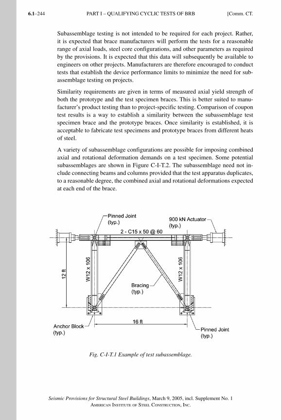
Seismic Provisions for Structural Steel Buildings, March 9, 2005, incl. Supplement No. 1AMERICAN INSTITUTE OF STEEL CONSTRUCTION, INC.
6.1–244
Subassemblage testing is not intended to be required for each project. Rather, it is expected that brace manufacturers will perform the tests for a reasonable range of axial loads, steel core configurations, and other parameters as required by the provisions. It is expected that this data will subsequently be available to engineers on other projects. Manufacturers are therefore encouraged to conduct tests that establish the device performance limits to minimize the need for sub-assemblage testing on projects.
Similarity requirements are given in terms of measured axial yield strength of both the prototype and the test specimen braces. This is better suited to manu-facturer’s product testing than to project-specific testing. Comparison of coupon test results is a way to establish a similarity between the subassemblage test specimen brace and the prototype braces. Once similarity is established, it is acceptable to fabricate test specimens and prototype braces from different heats of steel.
A variety of subassemblage configurations are possible for imposing combined axial and rotational deformation demands on a test specimen. Some potential subassemblages are shown in Figure C-I-T.2. The subassemblage need not in-clude connecting beams and columns provided that the test apparatus duplicates, to a reasonable degree, the combined axial and rotational deformations expected at each end of the brace.
Fig. C-I-T.1 Example of test subassemblage.
PART I – QUALIFYING CYCLIC TESTS OF BRB [Comm. CT.
SeismicProvComm1.indd 244SeismicProvComm1.indd 244 9/8/06 3:13:46 PM9/8/06 3:13:46 PMProcess BlackProcess Black
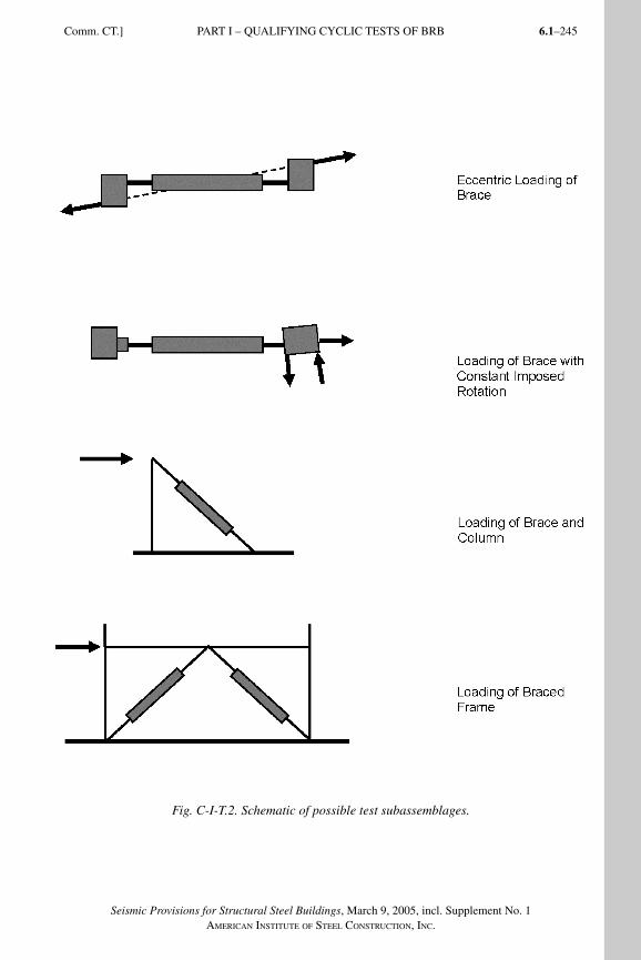
6.1–245
Seismic Provisions for Structural Steel Buildings, March 9, 2005, incl. Supplement No. 1AMERICAN INSTITUTE OF STEEL CONSTRUCTION, INC.
Comm. CT.] PART I – QUALIFYING CYCLIC TESTS OF BRB
Fig. C-I-T.2. Schematic of possible test subassemblages.
SeismicProvComm1.indd 245SeismicProvComm1.indd 245 9/8/06 3:13:47 PM9/8/06 3:13:47 PMProcess BlackProcess Black
Seismic Provisions for Structural Steel Buildings, March 9, 2005, incl. Supplement No. 1AMERICAN INSTITUTE OF STEEL CONSTRUCTION, INC.
6.1–246
Rotational demands may be concentrated in the steel core extension in the region just outside the buckling restraining mechanism. Depending on the magnitude of the rotational demands, limited flexural yielding of the steel core extension may occur. Rotational demands can also be accommodated by other means, such as tolerance in the buckling restraint layer or mechanism, elastic flexibility of the brace and steel core extension, or through the use of pins or spherical bearing assemblies. It is in the engineer’s best interest to include in a subassemblage testing all components that contribute significantly to accommodating rotational demands.
It is intended that the subassemblage test specimen be larger in axial-force ca-pacity than the prototype. However, the possibility exists for braces to be de-signed with very large axial forces. Should the brace yield force be so large as to make subassemblage testing impractical, the engineer is expected to make use of the provisions that allow for alternate testing programs, based on building official approval and qualified peer review. Such programs may include, but are not limited to, nonlinear finite element analysis, partial specimen testing, and reduced-scale testing, in combination with full-scale uniaxial testing where ap-plicable or required.
The steel core material was not included in the list of requirements. The more critical parameter, calculated margin of safety for the steel core projection stabil-ity, is required to meet or exceed the value used in the prototype. The method of calculating the steel core projection stability should be included in the design methodology.
CT5. BRACE TEST SPECIMENThe objective of brace test specimen testing is to establish basic design param-eters for the BRBF system.
It is recognized that the fabrication tolerances used by brace manufacturers to achieve the required brace performance may be tighter than those used for other fabricated structural steel members. The engineer is cautioned against including excessively prescriptive brace specifications, as the intent of these provisions is that the fabrication and supply of the braces is achieved through a performance-based specification process. It is considered sufficient that the manufacture of the test specimen and the prototype braces be conducted using the same quality control and assurance procedures, and the braces be designed using the same design methodology.
The engineer should also recognize that manufacturer process improvements over time may result in some manufacturing and quality control and assurance procedures changing between the time of manufacture of the brace test specimen and of the prototype. In such cases reasonable judgment is required.
The allowance of previous test data (similarity) to satisfy these provisions is less restrictive for uniaxial testing than for subassemblage testing. Subassemblage test specimen requirements are described in Section CT4.
PART I – QUALIFYING CYCLIC TESTS OF BRB [Comm. CT.
SeismicProvComm1.indd 246SeismicProvComm1.indd 246 9/8/06 3:13:47 PM9/8/06 3:13:47 PMProcess BlackProcess Black
6.1–247
Seismic Provisions for Structural Steel Buildings, March 9, 2005, incl. Supplement No. 1AMERICAN INSTITUTE OF STEEL CONSTRUCTION, INC.
A considerable number of uniaxial tests have been performed on some brace systems and the engineer is encouraged, wherever possible, to submit previous test data to meet these provisions. Relatively few subassemblage tests have been performed. This type of testing is considered a more demanding test of the over-all brace performance.
CT5.4. Connection DetailsIn many cases it will not be practical or reasonable to test the exact brace con-nections present in the prototype. These provisions are not intended to require such testing. In general, the demands on the steel core extension to gusset-plate connection are well defined due to the known axial capacity of the brace and the limited flexural capacity of the steel core extension. While the subsequent design of the bolted or welded gusset-plate connection is itself a complicated issue and the subject of continuing investigation, it is not intended that these connections become the focus of the testing program.
For the purposes of utilizing previous test data to meet the requirements of this Appendix, the requirements for similarity between the brace and subassemblage brace test specimen can be considered to exclude the steel core extension con-nection to frame.
CT5.5. MaterialsThe intent of the provisions is to allow test data from previous test programs to be presented where possible. See Section CT4 for additional commentary.
CT5.6. ConnectionsThe intent of this provision is to ensure that the end connections of the brace test specimen reasonably represent those of the prototype. It is possible that due to fabrication or assembly constraints variations in fit-up, faying-surface prepara-tion, or bolt or pin hole fabrication and size may occur. In certain cases, such variations may not be detrimental to the qualification of a successful cyclic test. The final acceptability of variations in brace-end connections rests on the opin-ion of the building official.
CT6. LOADING HISTORY
CT6.3. Loading SequenceThe subassemblage test specimen is required to undergo combined axial and rotational deformations similar to those in the prototype. It is recognized that identical braces, in different locations in the building, will undergo different maximum axial and rotational deformation demands. In addition, the maximum rotational and axial deformation demands may be different at each end of the brace. The engineer is expected to make simplifying assumptions to determine the most appropriate combination of rotational and axial deformation demands for the testing program.
Comm. CT.] PART I – QUALIFYING CYCLIC TESTS OF BRB
SeismicProvComm1.indd 247SeismicProvComm1.indd 247 9/8/06 3:13:47 PM9/8/06 3:13:47 PMProcess BlackProcess Black
Seismic Provisions for Structural Steel Buildings, March 9, 2005, incl. Supplement No. 1AMERICAN INSTITUTE OF STEEL CONSTRUCTION, INC.
6.1–248
Some subassemblage configurations will require that one deformation quantity be fixed while the other is varied as described in the test sequence above. In such a case, the rotational quantity may be applied and maintained at the maximum value, and the axial deformation applied according to the test sequence. The en-gineer may wish to perform subsequent tests on the same subassemblage speci-men to bound the brace performance.
The loading sequence requires each tested brace to achieve ductilities corre-sponding to 2.0 times the design story drift and a cumulative inelastic axial duc-tility capacity of 200. Both of these requirements are based on a study in which a series of nonlinear dynamic analyses was conducted on model buildings in order to investigate the performance of this system. The ductility capacity requirement represents a mean of response values (Sabelli and others, 2003). The cumulative ductility requirement is significantly higher than expected for the design basis earthquake, but testing of braces has shown this value to be easily achieved. It is expected that as more test data and building analysis results become available these requirements may be revisited.
The ratio of brace yield deformation, Δby, to the brace deformation correspond-ing to the design story drift, Δbm, must be calculated in order to define the testing protocol. This ratio is typically the same as the ratio of the displacement ampli-fication factor (as defined in the applicable building code) to the actual over-strength of the brace; the minimum overstrength is determined by the resistance factor (LRFD) or the safety factor (ASD) in Section 16.2a.
Engineers should note that there is a minimum brace deformation demand, Δbm, corresponding to 1 percent story drift (Section T2); provision of overstrength be-yond that required to so limit the design story drift may not be used as a basis to reduce the testing protocol requirements. Testing to at least twice this minimum (in other words, to 2 percent drift) is required.
Table C-T6-1 shows an example brace test protocol. For this example, it is as-sumed that the brace deformation corresponding to the design story drift is four times the yield deformation; it is also assumed that the design story drift is larger than the 1 percent minimum. The test protocol is then constructed from steps 1 through 4 of Section T6.3. In order to calculate the cumulative inelastic deforma-tion, the cycles are converted from multiples of brace deformation at the design story drift, Δbm, to multiples of brace yield deformation, Δby. Since the cumula-tive inelastic drift at the end of the 2.0Δbm cycles is less than the minimum of 200Δby required for brace tests, additional cycles to 1.5Δbm are required. At the end of three such cycles, the required cumulative inelastic deformation has been reached.
PART I – QUALIFYING CYCLIC TESTS OF BRB [Comm. CT.
SeismicProvComm1.indd 248SeismicProvComm1.indd 248 9/8/06 3:13:48 PM9/8/06 3:13:48 PMProcess BlackProcess Black
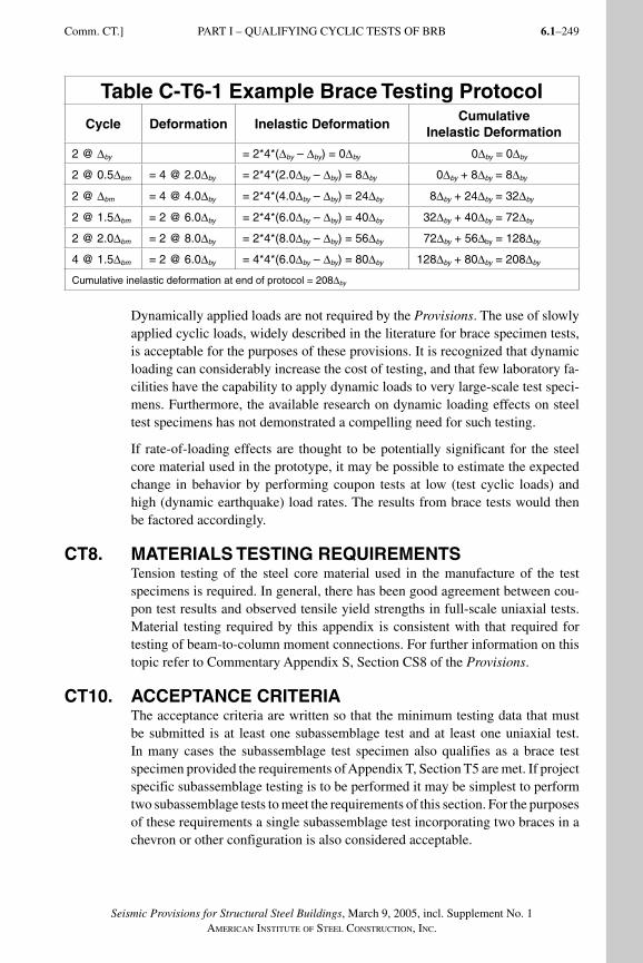
6.1–249
Seismic Provisions for Structural Steel Buildings, March 9, 2005, incl. Supplement No. 1AMERICAN INSTITUTE OF STEEL CONSTRUCTION, INC.
Table C-T6-1 Example Brace Testing ProtocolCycle Deformation Inelastic Deformation
Cumulative Inelastic Deformation
2 @ Δby = 2*4*(Δby – Δby) = 0Δby 0Δby = 0Δby
2 @ 0.5Δbm = 4 @ 2.0Δby = 2*4*(2.0Δby – Δby) = 8Δby 0Δby + 8Δby = 8Δby
2 @ Δbm = 4 @ 4.0Δby = 2*4*(4.0Δby – Δby) = 24Δby 8Δby + 24Δby = 32Δby
2 @ 1.5Δbm = 2 @ 6.0Δby = 2*4*(6.0Δby – Δby) = 40Δby 32Δby + 40Δby = 72Δby
2 @ 2.0Δbm = 2 @ 8.0Δby = 2*4*(8.0Δby – Δby) = 56Δby 72Δby + 56Δby = 128Δby
4 @ 1.5Δbm = 2 @ 6.0Δby = 4*4*(6.0Δby – Δby) = 80Δby 128Δby + 80Δby = 208Δby
Cumulative inelastic deformation at end of protocol = 208Δby
Dynamically applied loads are not required by the Provisions. The use of slowly applied cyclic loads, widely described in the literature for brace specimen tests, is acceptable for the purposes of these provisions. It is recognized that dynamic loading can considerably increase the cost of testing, and that few laboratory fa-cilities have the capability to apply dynamic loads to very large-scale test speci-mens. Furthermore, the available research on dynamic loading effects on steel test specimens has not demonstrated a compelling need for such testing.
If rate-of-loading effects are thought to be potentially significant for the steel core material used in the prototype, it may be possible to estimate the expected change in behavior by performing coupon tests at low (test cyclic loads) and high (dynamic earthquake) load rates. The results from brace tests would then be factored accordingly.
CT8. MATERIALS TESTING REQUIREMENTSTension testing of the steel core material used in the manufacture of the test specimens is required. In general, there has been good agreement between cou-pon test results and observed tensile yield strengths in full-scale uniaxial tests. Material testing required by this appendix is consistent with that required for testing of beam-to-column moment connections. For further information on this topic refer to Commentary Appendix S, Section CS8 of the Provisions.
CT10. ACCEPTANCE CRITERIAThe acceptance criteria are written so that the minimum testing data that must be submitted is at least one subassemblage test and at least one uniaxial test. In many cases the subassemblage test specimen also qualifies as a brace test specimen provided the requirements of Appendix T, Section T5 are met. If project specific subassemblage testing is to be performed it may be simplest to perform two subassemblage tests to meet the requirements of this section. For the purposes of these requirements a single subassemblage test incorporating two braces in a chevron or other configuration is also considered acceptable.
Comm. CT.] PART I – QUALIFYING CYCLIC TESTS OF BRB
SeismicProvComm1.indd 249SeismicProvComm1.indd 249 9/8/06 3:13:48 PM9/8/06 3:13:48 PMProcess BlackProcess Black
Seismic Provisions for Structural Steel Buildings, March 9, 2005, incl. Supplement No. 1AMERICAN INSTITUTE OF STEEL CONSTRUCTION, INC.
6.1–250
Depending on the means used to connect the test specimen to the subassemblage or test apparatus, and the instrumentation system used, bolt slip may appear in the load versus displacement history for some tests. This may appear as a series of downward spikes in the load versus displacement plot and is not generally a cause for concern, provided the behavior does not adversely affect the perfor-mance of the brace or brace connection.
These acceptance criteria are intended to be minimum requirements. The 1.3 limit in Section T10, requirement (4), is essentially a limitation on β. These pro-visions were developed assuming that β < 1.3 so this provision has been included in the test requirements. Currently available braces should be able to satisfy this requirement.
PART I – QUALIFYING CYCLIC TESTS OF BRB [Comm. CT.
SeismicProvComm1.indd 250SeismicProvComm1.indd 250 9/8/06 3:13:48 PM9/8/06 3:13:48 PMProcess BlackProcess Black
6.1–251
Seismic Provisions for Structural Steel Buildings, March 9, 2005, incl. Supplement No. 1AMERICAN INSTITUTE OF STEEL CONSTRUCTION, INC.
APPENDIX W
WELDING PROVISIONS
CW1. SCOPEProvisions for welded details, welding materials, welding inspection and test-ing personnel, and related items have been included in Appendix W until such time as they have been adopted by the AWS or other accredited organization in a suitable standard for seismic welding practices. At the time of publication of the Provisions, these items have been planned for inclusion in such a standard, but final ratification and publication of these provisions had not yet been com-pleted. Although the planned standard includes numerous other provisions and also additional details, conditions and alternatives regarding those cited here, the Provisions include the following items because they are considered essential to maintain the material properties and proper details necessary for adequate seismic performance. Upon adoption and publication of such a standard by AWS or other accredited organization, it is anticipated that this Appendix will be with-drawn from the Provisions, with reference made to the new standard.
CW2. STRUCTURAL DESIGN DRAWINGS AND SPECIFICATIONS, SHOP DRAWINGS, AND ERECTION DRAWINGSThe presence of backing, weld tabs and welds between these attachments and the members they are attached to may affect the flow of stresses around the connec-tions and contribute to stress concentrations. Some backing and tabs are in posi-tions that make them difficult to remove without damaging the adjacent material, and test data demonstrates that acceptable performance can be achieved without their removal. Backing removal may be impractical and unnecessary in locations such as column splices. Backing removal is impossible at the inside corners of small box sections, and at column splices of box sections.
Analysis and testing has demonstrated that the naturally occurring unfused edge of steel backing that contacts the column face in a beam to column connection constitutes a severe stress raiser. By placing a fillet weld between the steel back-ing and the column face, this concentration can be significantly reduced.
Weld tab removal may be impractical, or even harmful, in some locations, such as at the radius of a rolled column. In general, weld tabs should not be used in the k-area, but if used, are best left in place rather than risking the damage that might occur during tab removal.
SeismicProvComm1.indd 251SeismicProvComm1.indd 251 9/8/06 3:13:48 PM9/8/06 3:13:48 PMProcess BlackProcess Black
Seismic Provisions for Structural Steel Buildings, March 9, 2005, incl. Supplement No. 1AMERICAN INSTITUTE OF STEEL CONSTRUCTION, INC.
6.1–252
Reinforcing fillet welds are typically used in tee and corner joints where the load is perpendicular to the weld axis. A reinforcing fillet weld applied to a joint reduces the stress concentration of a nearly 90° intersection between the weld face or root, and the adjacent steel member. Such reinforcement is not required for most groove welds in tee or corner joints.
Analysis and research have shown that the shape of the weld access hole can have a significant effect on the behavior of moment connections. The use of weld access holes, other than those prescribed by the Specification, has not been found necessary for locations such as column splices. Care should be exercised to avoid specifying special weld access hole geometries when not justified. In some situations, no weld access holes are desirable, such as in end plate connections.
In common frame configurations, specific assembly order, welding sequence, welding technique and other special precautions should not be necessary. It is anticipated that such additional requirements will only be required for special cases, such as those of unusually high restraint.
CW3. PERSONNEL
CW3.1. QC Welding InspectorsThe inspector should be familiar with the Provisions and the AWS D1.1 Struc-tural Welding Code—Steel. Because the Contractor’s welding inspector typically has a more limited range of inspection tasks, repeated consistently on the same type of work and the same types of materials, it is not required that the QC weld-ing inspector have the same broad range of knowledge, nor as many years of experience, as QA welding inspectors, who may encounter a broader range of materials, details, and situations. Also, see Commentary CW3.2.
CW3.2. QA Welding InspectorsAWS B5.1 contains the same requirements for experience, education, training, and body of knowledge as the AWS QC1—Standard for AWS Certification of Welding Inspectors. The primary difference is in the examination provisions. Under AWS B5.1, the employer of other appropriate entity may test the candi-date, whereas under AWS QC1, the testing must be conducted by AWS.
CW3.3. Nondestructive Testing TechniciansUltrasonic technicians are typically certified by the employer in accordance with ASNT guidelines (SNT-TC-1a). ASNT CP-189 contains similar provisions, but is written as a standard rather than a guideline.
Requirements for Level II certification may vary significantly between inspec-tion and testing agencies. ASNT Level III technicians are not required to perform a hands-on practical test as a part of their ASNT examination, but typically have the skills to perform testing on a project. Those technicians classified as Level III, without ASNT examination, typically serve more training and supervisory roles and may not maintain the skills to perform project testing.
PART I – WELDING PROVISIONS [Comm. CW.
SeismicProvComm1.indd 252SeismicProvComm1.indd 252 9/8/06 3:13:48 PM9/8/06 3:13:48 PMProcess BlackProcess Black
6.1–253
Seismic Provisions for Structural Steel Buildings, March 9, 2005, incl. Supplement No. 1AMERICAN INSTITUTE OF STEEL CONSTRUCTION, INC.
Research and SAC studies have shown a wide variation of ultrasonic testing (UT) personnel skills for flaw detection using current AWS D1.1, Section 6, Part F procedures. Although not required by the Provisions, a practical examination to determine UT technician abilities using mockups of joints similar to project conditions is suggested. It is also suggested that third party organizations be used to conduct these examinations of UT technicians because they would pro-vide objective, comparable, and consistent testing with the potential to use the mockup samples for many examinees. Joint mockups with representative flaws used for such examinations are expensive and difficult to fabricate.
CW4. NONDESTRUCTIVE TESTING PROCEDURESIn order to improve the reliability of ultrasonic testing (UT), written procedures specific to the type or types of joints to be tested must be developed and tested on weld samples using standard reflectors. These procedures contain more specific information than the more generic provisions of AWS D1.1 Section 6, Part F.
ASTM E709 provides specific provisions regarding the techniques of performing magnetic particle testing (MT) and the evaluation techniques of welds using MT.
CW5. ADDITIONAL WELDING PROVISIONS
CW5.1. Intermixed Filler MetalsWhen intermixing weld deposits made using self-shield flux-cored welding (FCAW-S) electrodes with weld deposits made using other welding processes, the weld where the intermix has occurred may exhibit degradation of notch toughness in the intermixed deposit. Testing is done to ensure the minimum notch toughness requirements of these provisions are met in this intermixed region. Testing of intermixed weld metal is only required when the FCAW-S process is used in combination with another welding process, which includes FCAW-G. It is not required when welding one FCAW-S electrode over another FCAW-S electrode. It is not required when welding processes other than FCAW-S are used, regardless of combination.
A variety of intermix tests were performed before the issuance of the Provisions, including tests performed in accordance with FEMA 353, research performed in conjunction with various SAC investigations, and other independent research. Even though some of the details of these other tests are somewhat different than those of FEMA 353, results from alternative tests may be accepted by the engi-neer. The engineer should evaluate the relative similarity of the alternative tests to those described in FEMA 353. The contractor should provide sufficient back-ground documentation to the engineer for this evaluation. It is anticipated that AWS or another organization will adopt specific standards for performing tests on intermixed filler metals similar to those tests of FEMA 353, and these will be suitable for the purposes of the Provisions.
Comm. CW.] PART I – WELDING PROVISIONS
SeismicProvComm1.indd 253SeismicProvComm1.indd 253 9/8/06 3:13:49 PM9/8/06 3:13:49 PMProcess BlackProcess Black
Seismic Provisions for Structural Steel Buildings, March 9, 2005, incl. Supplement No. 1AMERICAN INSTITUTE OF STEEL CONSTRUCTION, INC.
6.1–254
CW5.2. Filler Metal Diffusible HydrogenAll welding electrodes are expected to meet the diffusible hydrogen require-ments for H16 (AWS A4.3). This requirement also applies to each SAW elec-trode/flux combination to be used on the project. The Provisions require that the filler metals used not exceed a hydrogen content of 16 ml/100 g of deposited weld metal. The manufacturer’s standard test for conformance with the H16 lim-it is adequate, provided the manufacturer’s certificate of conformance contains the test results.
The applicable filler metal specifications for FCAW, and GMAW when per-formed with composite electrodes, do not require testing in accordance with AWS A4.3 to determine diffusible hydrogen content. This testing is beyond that required by the filler metal specifications for these filler metals.
Rather than test for diffusible hydrogen, SMAW electrodes with low hydrogen coatings are required by the applicable filler metal specifications to have the coating moisture content measured as part of the classification testing. The re-sults are expressed as a percent moisture content, on a weight (mass) basis. Sat-isfactory conformance with these moisture content requirements is a suitable substitute for diffusible hydrogen testing, and such electrodes should be deemed to comply with the H16 requirement.
Solid electrodes for GMAW routinely deposit weld metal well within the limits of H16, and therefore testing is waived. GMAW with composite (metal-cored) electrodes require testing.
CW5.3. Gas-Shielded Welding ProcessesWhen gas-shielded processes are used, weld metal ductility and CVN toughness may degrade from moderate air movement and the subsequent loss of shielding. Even before porosity is noted in visual inspection, notch toughness has been shown to decrease in gas-shielded welds. Self-shielded processes (SMAW, SAW, FCAW-S) are considerably more tolerant of air movement.
AWS D1.1 has a maximum wind speed limit of 5 mph (8 kph). The more con-servative value of 3 mph (5 kph) has been imposed to ensure adequate CVN toughness in welds that are part of the SLRS.
Wind speed is to be estimated in the immediate vicinity of the weld, where the shielding gas may be affected. Precise monitoring of wind speed is not intended. Three mile per hour winds (5 kph) will cause modest drifting of smoke or weld-ing fume. Higher wind speeds can be felt on the face and as well as cause modest rippling of water surfaces.
CW5.4. Maximum Interpass TemperaturesVery high interpass temperatures cause very slow weld cooling rates that ad-versely affect weld and heat-affected zone (HAZ) mechanical properties, par-ticularly notch toughness and strength, and therefore may need to be limited to ensure adequate performance. In contrast, minimum preheat and interpass temperatures are based on avoidance of cracking.
PART I – WELDING PROVISIONS [Comm. CW.
SeismicProvComm1.indd 254SeismicProvComm1.indd 254 9/8/06 3:13:49 PM9/8/06 3:13:49 PMProcess BlackProcess Black
6.1–255
Seismic Provisions for Structural Steel Buildings, March 9, 2005, incl. Supplement No. 1AMERICAN INSTITUTE OF STEEL CONSTRUCTION, INC.
The 550 °F (300 °C) maximum temperature is a conservative value selected based upon the type of steels used in the SLRS. Higher interpass temperatures may be acceptable, and are permitted if the higher value is established by testing.
CW5.5. Weld TabsWelds are sometimes specified for the full length of a connection. Weld tabs are used to permit the starts and stops of the weld passes to be placed outside the weld region itself, allowing for removal of the start and stop conditions and their associated discontinuities. Because the end of the weld, after tab removal, is an outside surface that needs to be notch-free, proper removal methods and subse-quent finishing is necessary.
At continuity plates, the end of the continuity plate to column flange weld near the column flange tip permits the use of a full weld tab, and removal is generally efficient if properly detailed. At the opposite end of the continuity plate to col-umn flange weld, near the column radius, weld tabs are not generally desirable and may not be practicable because of clip size and k-area concerns. Weld tabs at this location, if used, should not be removed because the removal process has the potential of causing more harm than good.
CW5.6. Bottom Flange Welding SequenceStaggering the weld starts and stops on opposite sides of the beam web, and completion of each weld layer prior to starting the next layer, avoids the problem of incomplete fusion and trapped slag under the beam web against the column face, provided proper weld cleaning is performed after each weld pass is deposited.
CW6. ADDITIONAL WELDING PROVISIONS FOR DEMAND CRITICAL WELDS ONLY
CW6.1. Welding ProcessesThe SMAW and FCAW processes have been successfully used for connection qualification testing in the SAC project and numerous other connection qualifi-cation tests. In Japan, GMAW has also been used. The SAW process, although not specifically used in seismic moment connection testing, has been included as an acceptable process for demand critical welds because the heat input levels may be similar to those of the other three processes and because appropriate mechanical properties can be achieved. These four welding processes are also considered prequalified by AWS D1.1.
For processes such as ESW and EGW, the heat input level is considerably high-er than that of the other four processes, and there has not been general testing proving the acceptability of these processes for demand critical welds. However, these processes may have had limited connection qualification tests performed for certain applications, and their use in such applications may be approved by the engineer.
Comm. CW.] PART I – WELDING PROVISIONS
SeismicProvComm1.indd 255SeismicProvComm1.indd 255 9/8/06 3:13:49 PM9/8/06 3:13:49 PMProcess BlackProcess Black
Seismic Provisions for Structural Steel Buildings, March 9, 2005, incl. Supplement No. 1AMERICAN INSTITUTE OF STEEL CONSTRUCTION, INC.
6.1–256
CW6.2. Filler Metal PackagingFCAW electrodes may contain a seam along the electrode length as a part of the manufacturing process. The seam may allow the flux core to absorb moisture when exposed to humid conditions during storage. FCAW electrode packaging ranges from simple cardboard boxes and plastic bags, which provide little protection from moisture, to hermetically sealed foil bags that are moisture resistant.
Commonly, SMAW low-hydrogen electrodes packaging is hermetically sealed metal boxes that prevent moisture penetration. If the container has been damaged or torn, the electrodes must be baked dry prior to use.
Some electrode lubricants may increase the level of diffusible hydrogen during welding, increasing the risk of hydrogen-assisted cracking. Lubricants not asso-ciated with the original electrode manufacturer’s product are not permitted.
CW6.3. Exposure Limitations on FCAW ElectrodesFCAW electrodes may contain a seam along the electrode length as a part of the manufacturing process. The seam may allow the flux core to absorb moisture when exposed to humid conditions during use. The rate of moisture absorption is dependent on many factors, including the manufacturing process of the FCAW wire and the nature of the flux contained within the wire, and therefore these provisions are specific to the filler metal manufacturer’s brand and type of electrode.
In the absence of specific manufacturer’s recommendations, 72 hours is a con-servative upper limit for electrode exposure. This limit is based upon tests on a variety of FCAW wires from various manufacturers.
When welding is suspended, one may store the electrode in protective packag-ing, where no additional accumulation of moisture is expected to occur. The type of protective packaging needed depends upon the conditions that the electrodes will be exposed to. The exposure time resumes when the filler metal is removed from the protective packaging and put back onto the welding machine.
CW6.4. Tack WeldsBy placing the tack welds within the joint, the potential for surface notches and hard heat-affected zones is minimized. The HAZ of the tack weld will be tem-pered by subsequent passes when placed within the joint.
Tack welds for beam flange to column welds are to be made in the weld groove. Steel backing may be tack welded to the column under the beam flange, where a reinforcing fillet weld will be placed. Tack welds between steel backing and the underside of beam flanges are prohibited, as they create a notch effect in the beam flange. Any tack welds holding weld tabs, if made on the outside of the joint, are required to be removed.
PART I – WELDING PROVISIONS [Comm. CW.
SeismicProvComm1.indd 256SeismicProvComm1.indd 256 9/8/06 3:13:49 PM9/8/06 3:13:49 PMProcess BlackProcess Black
6.1–257
Seismic Provisions for Structural Steel Buildings, March 9, 2005, incl. Supplement No. 1AMERICAN INSTITUTE OF STEEL CONSTRUCTION, INC.
APPENDIX X
WELD METAL/WELDING PROCEDURE SPECIFICATION NOTCH TOUGHNESS
VERIFICATION TEST
CX1. SCOPEAppendix X applies only for filler metals to be used for demand critical welds. Filler metals used to make other welds covered by this code are not required to be tested in accordance with this Appendix.
All component tests conducted in the SAC project were conducted at room temperature, approximately 70 °F (21 °C), at which it was determined that an adequate Charpy V-Notch (CVN) toughness is 40 ft-lbs (54 J). The lowest an-ticipated service temperature (LAST) of most buildings is 50 °F (10 °C). Con-sidering the difference in loading rates between seismic motions and CVN test-ing, and the temperature increase of weldments under seismic loads, the CVN testing temperature of 70 °F (21 °C) is considered adequate for use at 50 °F (10 °C) LAST.
During the SAC study [see FEMA 355B, section 2.3.3.5 (FEMA, 2000d)], it was deemed important to verify the filler metal and welding procedure specification (WPS) to ensure that this notch toughness was provided. Appendix X testing requirements for 40 ft-lb (54 J) at 70 °F (21°C) are intended to verify that at most common service temperatures, the minimum notch toughness is provided to ensure satisfactory performance in seismic joints.
FEMA (FEMA, 2000b) first published this procedure for qualifying filler met-als to meet the recommended CVN toughness requirements of 40 ft-lb (54 J) at 70 °F (21 °C). The test procedure and test temperatures vary from existing AWS requirements used in existing AWS filler metal classification test standards. In the time since publication of the FEMA document, filler metal manufactur-ers have been conducting these tests and have been certifying those materials that meet this requirement. It is anticipated that AWS or another accredited organization will adopt this Appendix or a similar test program within their standards, and therefore this Appendix is included on an interim basis pending such adoption.
Filler metal classification testing is governed by the AWS A5 specifications that re-quire specific tests on weld metal that has been deposited using prescribed electrode diameters with prescribed welding conditions. Actual production welding may be performed with electrodes of different diameters and using considerably different welding variables (amperage, voltage, travel speed, electrode extension, position, plate thickness, joint geometry, preheat and interpass temperatures, shielding gas
SeismicProvComm1.indd 257SeismicProvComm1.indd 257 9/8/06 3:13:50 PM9/8/06 3:13:50 PMProcess BlackProcess Black
Seismic Provisions for Structural Steel Buildings, March 9, 2005, incl. Supplement No. 1AMERICAN INSTITUTE OF STEEL CONSTRUCTION, INC.
6.1–258
type and flow rate, for example). Such variables may considerably affect the actual tensile and CVN properties achieved in production welds. Although the require-ment of Section 7.3a, that all filler metals be classified under AWS A5 tests for a minimum of 20 ft-lbf at 0 °F (27 J at minus 17 °C), ensures that some minimum level of notch toughness will be provided, there is no guarantee that 40 ft-lbf (54 J) at 70 °F (21 °C) CVN toughness will be achieved under either the A5 prescribed conditions or the wide variety of possible welding procedures and cooling rates. For demand critical welds, additional testing is used to verify that the production weld will achieve the required higher level of notch toughness under conditions similar to those to be encountered in production.
CX2. TEST CONDITIONSHeat input affects weld metal and heat-affected zone (HAZ) cooling rates. High-er levels of heat input reduce cooling rates. Heat input also affects weld bead size, with higher levels of heat input creating larger weld beads. Both cooling rates and bead size may affect mechanical properties, and CVN toughness may be significantly changed with variations in heat input.
Testing of welds is required using high heat input levels and low heat input levels. By testing using bracketed heat inputs, requiring that production welding proce-dures fall within these tested heat inputs, and by testing the actual electrode diam-eter and production lot to be used in production, there is greater confidence that the as-deposited weld metal will provide the required level of CVN toughness.
Heat input is calculated by the following equation:
HI = 0.60 E I /S (CX2-1)
whereHI = heat inputE = arc voltageI = currentS = travel speed
When travel speed is measured in inches per minute (mm per minute), heat input is calculated in units of kilojoules per inch (kilojoules per mm). Some variation in heat input during the welding of the test plate is to be expected because of minor deviations from the three variables that determine heat input.
The heat input limits listed in Table I-X-1 are suggestions and deviation from these values is permitted. These heat input values have been suggested to en-courage some commonality between the limits selected by various filler metal manufacturers, and others that might do such testing. Some filler metals may not be capable of providing the required mechanical properties at the suggested heat input levels, therefore it is acceptable to use a tighter range of heat input values, provided the production WPS computed heat input values used are within this tighter ranger. If a broader range is desirable or achievable, the use of the larger range for testing is permitted, provided acceptable results are obtained in testing in accordance with this Appendix.
PART I – WELD METAL/WELDING PROCEDURE Comm. CX.]
SeismicProvComm1.indd 258SeismicProvComm1.indd 258 9/8/06 3:13:50 PM9/8/06 3:13:50 PMProcess BlackProcess Black
6.1–259
Seismic Provisions for Structural Steel Buildings, March 9, 2005, incl. Supplement No. 1AMERICAN INSTITUTE OF STEEL CONSTRUCTION, INC.
Comm. CX.] PART I – WELD METAL/WELDING PROCEDURE
Production WPS for demand critical welds are required to be based on the heat inputs used for testing the filler metal to be used in production. Production WPS may utilize any combination of welding variables that result in a computed heat input that is not greater than the high heat input test limit, or less than the low heat input test limit. It is not necessary for the Contractor to use the exact param-eters listed in this test (volts, amps, travel speed), but the parameters chosen must result in a calculated heat input between the high and low heat inputs tested. The use of heat input limits outside the limits of Table I-X-1 are acceptable provided the higher limits have been successfully tested. It is expected that heat input lev-els between these limits will result in acceptable mechanical properties.
CX3. TEST SPECIMENSThe test assembly may be restrained, or the plates preset in advance of welding, in order to preclude rejection of the test assembly due to excessive warpage.
In addition to heat input, preheat and interpass temperatures may affect the me-chanical properties of deposited weld metal. Testing according to this Appendix requires that preheat and interpass temperatures be within the prescribed ranges shown in Table I-X-1.
During testing, the test plate is heated to the minimum preheat temperature listed, and then welding begins. Welding is to continue without substantial, deliberate interruption until the minimum interpass temperature has been obtained. For the high heat input test, it may take several weld passes before the interpass tempera-ture is achieved. Once this point has been reached, all subsequent weld passes are to be made within the permitted interpass temperature range. Should the test plate temperature fall below the minimum interpass temperature for any reason, the test plate is heated to the minimum interpass temperature before welding is resumed. If the required interpass temperature is not achieved prior to inter-ruption of the welding operations, welding is not to resume until the prescribed interpass temperature is provided. Should the test plate exceed the prescribed maximum interpass temperature, welding shall be discontinued until the test plate cools below the stated maximum interpass temperature. This is likely to be required for the low heat input test.
Production preheat and interpass temperatures controls are to be in accordance with the production WPS, typically written to the requirements of AWS D1.1, and will likely not be the same as the temperature range limits of Table I-X-1.
The Appendix does not specify the position in which welding of the test plates is to be performed. Typically, test plate welding will be done in the flat position. For filler metals designed for vertical-up welding, flat position welding may be difficult. This Appendix does not require qualification testing of filler metals for the position in which production welding will be performed.
SeismicProvComm1.indd 259SeismicProvComm1.indd 259 9/8/06 3:13:50 PM9/8/06 3:13:50 PMProcess BlackProcess Black
Seismic Provisions for Structural Steel Buildings, March 9, 2005, incl. Supplement No. 1AMERICAN INSTITUTE OF STEEL CONSTRUCTION, INC.
6.1–260
CX4. ACCEPTANCE CRITERIATensile and elongation results obtained from welds made with heat input values between the high and low limits will likely be bracketed by the values obtained in the high and low heat input tests. The tensile strength and elongation require-ments for weld metal tensile test specimens stated are all minimum values, with no maximum values specified. All tensile testing is done at room temperature, regardless of LAST.
Notch toughness tends to deteriorate at both very high and very low heat input levels. Values obtained from welds made with heat input values between the high and low limits will likely be greater than the values obtained at the extremes. The CVN toughness values stated are all minimum values, with no maximum values specified. If adequate CVN values are achieved by testing at temperatures below the actual test temperatures required for the demand critical weld, it is not neces-sary to perform the test at the higher test temperature warranted for that weld.
This Appendix is not applicable to filler metals with a classification strength greater than E80 (E550), as the use of such filler metals in demand critical welds is not addressed by the Provisions.
PART I – WELD METAL/WELDING PROCEDURE [Comm. CX.
SeismicProvComm1.indd 260SeismicProvComm1.indd 260 9/8/06 3:13:50 PM9/8/06 3:13:50 PMProcess BlackProcess Black
6.1–261
Seismic Provisions for Structural Steel Buildings, March 9, 2005, incl. Supplement No. 1AMERICAN INSTITUTE OF STEEL CONSTRUCTION, INC.
PART II. COMPOSITE STRUCTURAL STEEL ANDREINFORCED CONCRETE BUILDINGS
C1. SCOPEThese Provisions for the seismic design of composite structural steel and rein-forced concrete buildings are based upon the 1994 NEHRP Provisions (FEMA, 1994) and subsequent modifications made in the 1997, 2000, and 2003 NEHRP Provisions (FEMA, 2003) and in ASCE 7 (ASCE, 2002). Since composite sys-tems are assemblies of steel and concrete components, Part I of these Provisions, the 2005 AISC Specification for Structural Steel Buildings (AISC, 2005), here-after referred to as the Specification and ACI 318 (ACI, 2002b), form an impor-tant basis for Part II. Notable changes in the composite column design provisions in Chapter I of the Specification will significantly reduce some of the conflicts between the Specification and ACI 318, and thus encourage the use of composite columns in all lateral load resisting systems.
The most important changes in this version of Part II are the inclusion of the new allowable strength design (ASD) format from the Specification and the ad-dition and moving of several sections to make Parts I and II more consistent. The intent to render the Part I and II provisions more uniform also led to some significant technical changes, including the introduction of the concept of pro-tected zones for the hinging regions in some structural systems. In addition, a number of important changes for the systems behavior factors (R, Cd and Ωo) have been introduced in ASCE 7 for composite systems. The latter was an effort to render the behavior factors more consistent between the different structural materials. Finally, because Sections 12 and 13 have been interchanged to follow Part I, numerous editorial changes have been made where the previous version referred to these sections. However, the technical changes in Sections 12 and 13 are minimal.
The available research demonstrates that properly detailed composite members and connections can perform reliably when subjected to seismic ground mo-tions. The most recent research in this area is the product of a U.S.–Japan joint project, whose results arrived too late for inclusion in the provisions (El-Tawil and Bracci, 2004; Goel, 2004); however, some of that research is cited in this Commentary. In particular, significant advances have taken place in the ability to analyze such structures (Spacone and El-Tawil, 2004); such advances are ex-pected to be incorporated into commercial software soon.
There is at present limited experience in the USA with composite building sys-tems subjected to extreme seismic loads and many of the recommendations herein are necessarily of a conservative and/or qualitative nature. Extensive de-sign and performance experience with this type of buildings in Japan clearly indicates that composite systems, due to their inherent rigidity and toughness,
SeismicProvComm2.indd 261SeismicProvComm2.indd 261 9/8/06 12:18:28 PM9/8/06 12:18:28 PMProcess BlackProcess Black
Seismic Provisions for Structural Steel Buildings, March 9, 2005, incl. Supplement No. 1AMERICAN INSTITUTE OF STEEL CONSTRUCTION, INC.
6.1–262
can equal or exceed the performance of reinforced concrete only or structural steel only buildings (Deierlein and Noguchi, 2004; Yamanouchi, Nishiyama and Kobayashi, 1998). Composite systems have been extensively used in tall build-ings throughout the world, and independent design specifications have been de-veloped for nonseismic loading cases [Eurocode 4 (ECS, 1994)].
Careful attention to all aspects of the design is necessary in the design of com-posite systems, particularly with respect to the general building layout and de-tailing of members and connections. Composite connection details are illustrated throughout this Commentary to convey the basic character of the force transfer in composite systems. However, these details should not necessarily be treated as design standards and the cited references provide more specific information on the design of composite connections. For a general discussion of these issues and some specific design examples, refer to Viest, Colaco, Furlong, Griffis, Leon and Wyllie (1997).
The design and construction of composite elements and systems continues to evolve in practice. Except where explicitly stated, these Provisions are not in-tended to limit the application of new systems for which testing and analysis demonstrates that the structure has adequate strength, ductility, and toughness.
It is generally anticipated that the overall behavior of the composite systems herein will be similar to that for counterpart structural steel systems or reinforced concrete systems and that inelastic deformations will occur in conventional ways, such as flexural yielding of beams in fully restrained (FR) moment frames or axial yielding and/or buckling of braces in braced frames. However, differential stiffness between steel and concrete elements is more significant in the calcula-tion of internal forces and deformations of composite systems than for structural steel only or reinforced concrete only systems. For example, deformations in composite elements can vary considerably due to the effects of cracking.
When systems have both ductile and nonductile elements, the relative stiffness of each should be properly modeled; the ductile elements can deform inelasti-cally while the nonductile elements remain nominally elastic. When using elas-tic analysis, member stiffness should be reduced to account for the degree of cracking at the onset of significant yielding in the structure. Additionally, it is necessary to account for material overstrength that may alter relative strength and stiffness.
C2. REFERENCED SPECIFICATIONS, CODES, AND STANDARDSThe majority of the specifications needed for Part II have already been refer-enced in Part I and are thus included by reference. Those listed here with their appropriate revision date are applicable to Part II only. A notable shift in this section is that the reference to ACI 318 has now been moved to Part I.
PART II – SCOPE [Comm. C1.
SeismicProvComm2.indd 262SeismicProvComm2.indd 262 9/8/06 12:18:29 PM9/8/06 12:18:29 PMProcess BlackProcess Black
6.1–263
Seismic Provisions for Structural Steel Buildings, March 9, 2005, incl. Supplement No. 1AMERICAN INSTITUTE OF STEEL CONSTRUCTION, INC.
C3. GENERAL SEISMIC DESIGN REQUIREMENTSThis section is consistent with Part I Section 3. See Part I Commentary Section C3.
C4. LOADS, LOAD COMBINATIONS, AND NOMINAL STRENGTHSThe requirements for loads and load combinations for composite structures are similar to those described in Part I Section 4, and this section has been rewritten to parallel that section. Specific seismic design, loading criteria, and usage limi-tations for composite structures are specified in the 2002 SEI/ASCE 7 provisions (ASCE, 2002).
The calculation of seismic loads for composite systems per the 2002 SEI/ASCE 7 provisions is the same as is described for steel structures in Part I Commentary Section C4. The seismic response modification factors R and Cd for some structural systems have been changed in SEI/ASCE 7 to make them more consistent with similar systems in structural steel only and reinforced concrete only systems. This is based on the fact that, when carefully designed and de-tailed according to these Provisions, the overall inelastic response for composite systems should be similar to comparable steel and reinforced concrete systems. Therefore, where specific loading requirements are not specified in the appli-cable building code for composite systems, appropriate values for the seismic response factors can be inferred from specified values for steel and/or reinforced concrete systems. These are predicated upon meeting the design and detailing requirements for the composite systems specified in these Provisions. As stated in the User Note, for systems not included in the applicable building code, the values should be taken from SEI/ASCE 7.
C5. MATERIALSThe limitations in Section 5.1 on structural steel grades used with Part II requirements are the same as those given in Part I, Sections 6 and 7. The limitations in Section 5.2 on specified concrete compressive strength in composite members are the same as those given in the Specification Chapter I and ACI 318 Chapter 21. While these limitations are particularly appropriate for construction in seismic design categories D and higher, they apply in any seismic design category when systems are designed with the assumption that inelastic deformation will be required.
At this time, there is insufficient data to generate specification requirements for the shear strength of studs subjected to inelastic cyclic loads, although it is clear that some strength and stiffness reduction occurs with cycling (McMullin and Astaneh, 1994; Civjan and Singh, 2003). The degradation in behavior is par-ticularly serious if the studs are subjected to combined tension and shear (Saari, Hajjar, Schultz and Shield, 2004), and a specific reduction for combined load cases is given in Section 16. For other composite members that are part of the SLRS, a reduction to 75 percent of the stud strength given in the Specification is suggested to allow for the effect of cyclic loads if the studs are expected to
Comm. C5.] PART II – MATERIALS
SeismicProvComm2.indd 263SeismicProvComm2.indd 263 9/8/06 12:18:29 PM9/8/06 12:18:29 PMProcess BlackProcess Black
Seismic Provisions for Structural Steel Buildings, March 9, 2005, incl. Supplement No. 1AMERICAN INSTITUTE OF STEEL CONSTRUCTION, INC.
6.1–264
yield. At this time, the ductility demands on shear studs in floor beams and dia-phragms are not well characterized, and thus only a suggestion is given in this Commentary.
C6. COMPOSITE MEMBERS
C6.1. ScopeThese Provisions address the seismic design requirements that should be applied in addition to the basic design requirements for gravity and wind loading.
C6.2. Composite Floor and Roof SlabsIn composite construction, floor and roof slabs typically consist of either com-posite or noncomposite metal deck slabs that are connected to the structural framing to provide an in-plane composite diaphragm that collects and distributes seismic loads. Generally, composite action is distinguished from noncomposite action on the basis of the out-of-plane shear and flexural behavior and design assumptions.
Composite metal deck slabs are those for which the concrete fill and metal deck work together to resist out-of-plane bending and out-of-plane shear. Flexural strength design procedures and codes of practice for such slabs are well estab-lished (ASCE, 1991a and 1991b; AISI, 2001; SDI, 2001a, 2001b).
Noncomposite metal deck slabs are one-way or two-way reinforced con-crete slabs for which the metal deck acts as formwork during construction, but is not relied upon for composite action. Noncomposite metal deck slabs, particularly those used as roofs, can be formed with metal deck and overlaid with insulating concrete fill that is not relied upon for out-of-plane strength and stiffness. Whether or not the slab is designed for composite out-of-plane action, the concrete fill inhibits buckling of the metal deck, increasing the in-plane strength and stiffness of the diaphragm over that of the bare steel deck.
The diaphragm should be designed to collect and distribute seismic loads to the seismic load resisting system. In some cases, loads from other floors should also be included, such as at a level where a change in the structural stiffness results in redistribution. Recommended diaphragm (in-plane) shear strength and stiffness values for metal deck and composite diaphragms are available for design from industry sources that are based upon tests and recommended by the applicable building code (SDI, 2004; SDI, 2001a, 2001b). In addition, research on compos-ite diaphragms has been reported in the literature (Easterling and Porter, 1994).
As the thickness of concrete over the steel deck is increased, the shear strength can approach that for a concrete slab of the same thickness. For example, in com-posite floor deck diaphragms having cover depths between 2 in. (51 mm) and 6 in. (152 mm), measured shear stresses on the order of 3.5 ′fc
(where ′fc
and f ′c are in units of psi) have been reported. In such cases, the diaphragm strength of concrete metal deck slabs can be conservatively based on the
PART II – MATERIALS [Comm. C5.
SeismicProvComm2.indd 264SeismicProvComm2.indd 264 9/8/06 12:18:30 PM9/8/06 12:18:30 PMProcess BlackProcess Black
6.1–265
Seismic Provisions for Structural Steel Buildings, March 9, 2005, incl. Supplement No. 1AMERICAN INSTITUTE OF STEEL CONSTRUCTION, INC.
principles of reinforced concrete design (ACI, 2002b) using the concrete and reinforcement above the metal deck ribs and ignoring the beneficial effect of the concrete in the flutes.
Shear forces are transferred through welds and/or shear devices in the collector and boundary elements. Fasteners between the diaphragm and the steel framing should be capable of transferring forces using either welds or shear devices. Where concrete fill is present, it is generally advisable to use mechanical de-vices such as headed shear stud connectors to transfer diaphragm forces between the slab and collector/boundary elements, particularly in complex shaped dia-phragms with discontinuities. However, in low-rise buildings without abrupt discontinuities in the shape of the diaphragms or in the seismic load resisting system, the standard metal deck attachment procedures may be acceptable.
C6.3. Composite BeamsThese provisions apply only to composite beams that are part of the seismic load resisting system.
When the design of a composite beam satisfies Equation 6-1, the strain in the steel at the extreme fiber will be at least five times the tensile yield strain prior to concrete crushing at strain equal to 0.003. It is expected that this ductility limit will control the beam geometry only in extreme beam/slab proportions.
While these Provisions permit the design of composite beams based solely upon the requirements in the Specification, the effects of reversed cyclic loading on the strength and stiffness of shear studs should be considered. This is particu-larly important for C-SMF where the design loads are calculated assuming large member ductility and toughness. In the absence of test data to support specific requirements in these Provisions, the following special measures should be con-sidered in C-SMF: (1) implementation of an inspection and quality assurance plan to insure proper welding of shear stud connectors to the beams (see Sec-tions 18 and 19); and (2) use of additional shear stud connectors beyond those required in the Specification immediately adjacent to regions of the beams where plastic hinging is expected.
C6.4. Encased Composite ColumnsThe basic requirements and limitations for determining the design strength of reinforced-concrete encased composite columns are the same as those in the Specification. Additional requirements for reinforcing bar details of composite columns that are not covered in the Specification are included based on provi-sions in ACI 318.
Composite columns can be an ideal solution for use in seismic regions because of their inherent structural redundancy (Viest and others, 1997; El-Tawil and Deierlein, 1999). For example, if a composite column is designed such that the structural steel can carry most or all of the dead load acting alone, then an extra degree of protection and safety is afforded, even in a severe earthquake where excursions into the inelastic range can be expected to deteriorate concrete cover
Comm. C6.] PART II – COMPOSITE MEMBERS
SeismicProvComm2.indd 265SeismicProvComm2.indd 265 9/8/06 12:18:30 PM9/8/06 12:18:30 PMProcess BlackProcess Black
Seismic Provisions for Structural Steel Buildings, March 9, 2005, incl. Supplement No. 1AMERICAN INSTITUTE OF STEEL CONSTRUCTION, INC.
6.1–266
and buckle reinforcing steel. However, as with any column of concrete and reinforcement, the designer should be aware of the constructability concerns with the placement of reinforcement and potential for congestion. This is particularly true at beam-to-column connections where potential interference between a steel spandrel beam, a perpendicular floor beam, vertical bars, joint ties, and shear stud connectors can cause difficulty in reinforcing bar placement and a potential for honeycombing of the concrete.
Seismic detailing requirements for composite columns are specified in the fol-lowing three categories: ordinary, intermediate, and special. The required level of detailing is specified in these Provisions for seismic systems in Sections 8 through 17. The ordinary detailing requirements of Section 6.4a are intended as basic requirements for all cases. Intermediate requirements are intended for seismic systems permitted in seismic design category C, and special require-ments are intended for seismic systems permitted in seismic design categories D and above.
C6.4a. Ordinary Seismic System RequirementsThese requirements are intended to supplement the basic requirements of the Specification for encased composite columns in all seismic design categories.
(1) Specific instructions are given for the determination of the nominal shear strength in concrete encased steel composite members including assignment of some shear to the reinforced concrete encasement. Examples for deter-mining the effective shear width, bw, of the reinforced concrete encasement are illustrated in Figure C-II-6.1. These provisions exclude any strength, Vc , assigned to concrete alone (Furlong, 1997).
(2) The provisions in this subsection require that shear connectors be provided to transfer all calculated axial forces between the structural steel and the concrete, neglecting the contribution of bond and friction. Friction between the structural steel and concrete is assumed to transfer the longitudinal shear stresses required to develop the plastic bending strength of the cross sec-tion. However, minimum shear studs should be provided according to the maximum spacing limit of 16 in. (406 mm). Further information regarding the design of shear connectors for encased members is available (Furlong, 1997; Griffis, 1992a, 1992b).
(3) The tie requirements in this section are essentially the same as those for composite columns in ACI 318 Chapter 10.
(4) The requirements for longitudinal bars are essentially the same as those that apply to composite columns for low- and nonseismic design as speci-fied in ACI 318. The distinction between load-carrying and restraining bars is made to allow for longitudinal bars (restraining bars) that are provided solely for erection purposes and to improve confinement of the concrete. Due to interference with steel beams framing into the encased members, the restraining bars are often discontinuous at floor levels and, therefore, are not included in determining the column strength.
PART II – COMPOSITE MEMBERS [Comm. C6.
SeismicProvComm2.indd 266SeismicProvComm2.indd 266 9/8/06 12:18:30 PM9/8/06 12:18:30 PMProcess BlackProcess Black
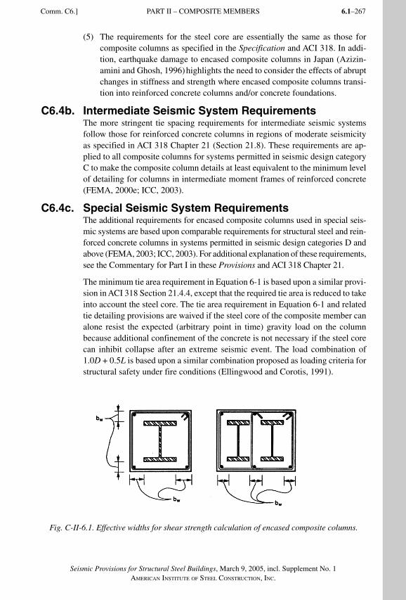
6.1–267
Seismic Provisions for Structural Steel Buildings, March 9, 2005, incl. Supplement No. 1AMERICAN INSTITUTE OF STEEL CONSTRUCTION, INC.
(5) The requirements for the steel core are essentially the same as those for composite columns as specified in the Specification and ACI 318. In addi-tion, earthquake damage to encased composite columns in Japan (Azizin-amini and Ghosh, 1996) highlights the need to consider the effects of abrupt changes in stiffness and strength where encased composite columns transi-tion into reinforced concrete columns and/or concrete foundations.
C6.4b. Intermediate Seismic System RequirementsThe more stringent tie spacing requirements for intermediate seismic systems follow those for reinforced concrete columns in regions of moderate seismicity as specified in ACI 318 Chapter 21 (Section 21.8). These requirements are ap-plied to all composite columns for systems permitted in seismic design category C to make the composite column details at least equivalent to the minimum level of detailing for columns in intermediate moment frames of reinforced concrete (FEMA, 2000e; ICC, 2003).
C6.4c. Special Seismic System RequirementsThe additional requirements for encased composite columns used in special seis-mic systems are based upon comparable requirements for structural steel and rein-forced concrete columns in systems permitted in seismic design categories D and above (FEMA, 2003; ICC, 2003). For additional explanation of these requirements, see the Commentary for Part I in these Provisions and ACI 318 Chapter 21.
The minimum tie area requirement in Equation 6-1 is based upon a similar provi-sion in ACI 318 Section 21.4.4, except that the required tie area is reduced to take into account the steel core. The tie area requirement in Equation 6-1 and related tie detailing provisions are waived if the steel core of the composite member can alone resist the expected (arbitrary point in time) gravity load on the column because additional confinement of the concrete is not necessary if the steel core can inhibit collapse after an extreme seismic event. The load combination of 1.0D + 0.5L is based upon a similar combination proposed as loading criteria for structural safety under fire conditions (Ellingwood and Corotis, 1991).
Fig. C-II-6.1. Effective widths for shear strength calculation of encased composite columns.
Comm. C6.] PART II – COMPOSITE MEMBERS
SeismicProvComm2.indd 267SeismicProvComm2.indd 267 9/8/06 12:18:30 PM9/8/06 12:18:30 PMProcess BlackProcess Black
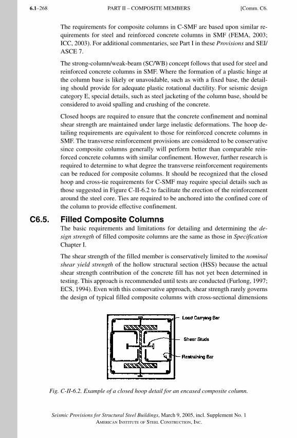
Seismic Provisions for Structural Steel Buildings, March 9, 2005, incl. Supplement No. 1AMERICAN INSTITUTE OF STEEL CONSTRUCTION, INC.
6.1–268
The requirements for composite columns in C-SMF are based upon similar re-quirements for steel and reinforced concrete columns in SMF (FEMA, 2003; ICC, 2003). For additional commentaries, see Part I in these Provisions and SEI/ASCE 7.
The strong-column/weak-beam (SC/WB) concept follows that used for steel and reinforced concrete columns in SMF. Where the formation of a plastic hinge at the column base is likely or unavoidable, such as with a fixed base, the detail-ing should provide for adequate plastic rotational ductility. For seismic design category E, special details, such as steel jacketing of the column base, should be considered to avoid spalling and crushing of the concrete.
Closed hoops are required to ensure that the concrete confinement and nominal shear strength are maintained under large inelastic deformations. The hoop de-tailing requirements are equivalent to those for reinforced concrete columns in SMF. The transverse reinforcement provisions are considered to be conservative since composite columns generally will perform better than comparable rein-forced concrete columns with similar confinement. However, further research is required to determine to what degree the transverse reinforcement requirements can be reduced for composite columns. It should be recognized that the closed hoop and cross-tie requirements for C-SMF may require special details such as those suggested in Figure C-II-6.2 to facilitate the erection of the reinforcement around the steel core. Ties are required to be anchored into the confined core of the column to provide effective confinement.
C6.5. Filled Composite ColumnsThe basic requirements and limitations for detailing and determining the de-sign strength of filled composite columns are the same as those in Specification Chapter I.
The shear strength of the filled member is conservatively limited to the nominal shear yield strength of the hollow structural section (HSS) because the actual shear strength contribution of the concrete fill has not yet been determined in testing. This approach is recommended until tests are conducted (Furlong, 1997; ECS, 1994). Even with this conservative approach, shear strength rarely governs the design of typical filled composite columns with cross-sectional dimensions
Fig. C-II-6.2. Example of a closed hoop detail for an encased composite column.
PART II – COMPOSITE MEMBERS [Comm. C6.
SeismicProvComm2.indd 268SeismicProvComm2.indd 268 9/8/06 12:18:31 PM9/8/06 12:18:31 PMProcess BlackProcess Black
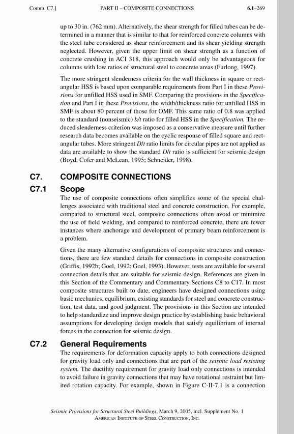
6.1–269
Seismic Provisions for Structural Steel Buildings, March 9, 2005, incl. Supplement No. 1AMERICAN INSTITUTE OF STEEL CONSTRUCTION, INC.
up to 30 in. (762 mm). Alternatively, the shear strength for filled tubes can be de-termined in a manner that is similar to that for reinforced concrete columns with the steel tube considered as shear reinforcement and its shear yielding strength neglected. However, given the upper limit on shear strength as a function of concrete crushing in ACI 318, this approach would only be advantageous for columns with low ratios of structural steel to concrete areas (Furlong, 1997).
The more stringent slenderness criteria for the wall thickness in square or rect-angular HSS is based upon comparable requirements from Part I in these Provi-sions for unfilled HSS used in SMF. Comparing the provisions in the Specifica-tion and Part I in these Provisions, the width/thickness ratio for unfilled HSS in SMF is about 80 percent of those for OMF. This same ratio of 0.8 was applied to the standard (nonseismic) b/t ratio for filled HSS in the Specification. The re-duced slenderness criterion was imposed as a conservative measure until further research data becomes available on the cyclic response of filled square and rect-angular tubes. More stringent D/t ratio limits for circular pipes are not applied as data are available to show the standard D/t ratio is sufficient for seismic design (Boyd, Cofer and McLean, 1995; Schneider, 1998).
C7. COMPOSITE CONNECTIONS
C7.1 ScopeThe use of composite connections often simplifies some of the special chal-lenges associated with traditional steel and concrete construction. For example, compared to structural steel, composite connections often avoid or minimize the use of field welding, and compared to reinforced concrete, there are fewer instances where anchorage and development of primary beam reinforcement is a problem.
Given the many alternative configurations of composite structures and connec-tions, there are few standard details for connections in composite construction (Griffis, 1992b; Goel, 1992; Goel, 1993). However, tests are available for several connection details that are suitable for seismic design. References are given in this Section of the Commentary and Commentary Sections C8 to C17. In most composite structures built to date, engineers have designed connections using basic mechanics, equilibrium, existing standards for steel and concrete construc-tion, test data, and good judgment. The provisions in this Section are intended to help standardize and improve design practice by establishing basic behavioral assumptions for developing design models that satisfy equilibrium of internal forces in the connection for seismic design.
C7.2 General RequirementsThe requirements for deformation capacity apply to both connections designed for gravity load only and connections that are part of the seismic load resisting system. The ductility requirement for gravity load only connections is intended to avoid failure in gravity connections that may have rotational restraint but lim-ited rotation capacity. For example, shown in Figure C-II-7.1 is a connection
Comm. C7.] PART II – COMPOSITE CONNECTIONS
SeismicProvComm2.indd 269SeismicProvComm2.indd 269 9/8/06 12:18:31 PM9/8/06 12:18:31 PMProcess BlackProcess Black
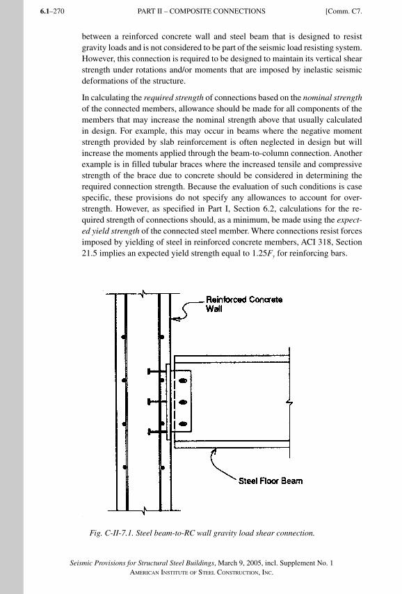
Seismic Provisions for Structural Steel Buildings, March 9, 2005, incl. Supplement No. 1AMERICAN INSTITUTE OF STEEL CONSTRUCTION, INC.
6.1–270
between a reinforced concrete wall and steel beam that is designed to resist gravity loads and is not considered to be part of the seismic load resisting system. However, this connection is required to be designed to maintain its vertical shear strength under rotations and/or moments that are imposed by inelastic seismic deformations of the structure.
In calculating the required strength of connections based on the nominal strength of the connected members, allowance should be made for all components of the members that may increase the nominal strength above that usually calculated in design. For example, this may occur in beams where the negative moment strength provided by slab reinforcement is often neglected in design but will increase the moments applied through the beam-to-column connection. Another example is in filled tubular braces where the increased tensile and compressive strength of the brace due to concrete should be considered in determining the required connection strength. Because the evaluation of such conditions is case specific, these provisions do not specify any allowances to account for over-strength. However, as specified in Part I, Section 6.2, calculations for the re-quired strength of connections should, as a minimum, be made using the expect-ed yield strength of the connected steel member. Where connections resist forces imposed by yielding of steel in reinforced concrete members, ACI 318, Section 21.5 implies an expected yield strength equal to 1.25Fy for reinforcing bars.
Fig. C-II-7.1. Steel beam-to-RC wall gravity load shear connection.
PART II – COMPOSITE CONNECTIONS [Comm. C7.
SeismicProvComm2.indd 270SeismicProvComm2.indd 270 9/8/06 12:18:31 PM9/8/06 12:18:31 PMProcess BlackProcess Black
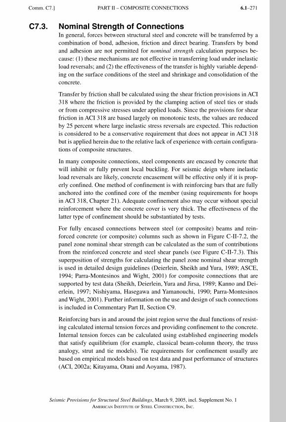
6.1–271
Seismic Provisions for Structural Steel Buildings, March 9, 2005, incl. Supplement No. 1AMERICAN INSTITUTE OF STEEL CONSTRUCTION, INC.
C7.3. Nominal Strength of ConnectionsIn general, forces between structural steel and concrete will be transferred by a combination of bond, adhesion, friction and direct bearing. Transfers by bond and adhesion are not permitted for nominal strength calculation purposes be-cause: (1) these mechanisms are not effective in transferring load under inelastic load reversals; and (2) the effectiveness of the transfer is highly variable depend-ing on the surface conditions of the steel and shrinkage and consolidation of the concrete.
Transfer by friction shall be calculated using the shear friction provisions in ACI 318 where the friction is provided by the clamping action of steel ties or studs or from compressive stresses under applied loads. Since the provisions for shear friction in ACI 318 are based largely on monotonic tests, the values are reduced by 25 percent where large inelastic stress reversals are expected. This reduction is considered to be a conservative requirement that does not appear in ACI 318 but is applied herein due to the relative lack of experience with certain configura-tions of composite structures.
In many composite connections, steel components are encased by concrete that will inhibit or fully prevent local buckling. For seismic deign where inelastic load reversals are likely, concrete encasement will be effective only if it is prop-erly confined. One method of confinement is with reinforcing bars that are fully anchored into the confined core of the member (using requirements for hoops in ACI 318, Chapter 21). Adequate confinement also may occur without special reinforcement where the concrete cover is very thick. The effectiveness of the latter type of confinement should be substantiated by tests.
For fully encased connections between steel (or composite) beams and rein-forced concrete (or composite) columns such as shown in Figure C-II-7.2, the panel zone nominal shear strength can be calculated as the sum of contributions from the reinforced concrete and steel shear panels (see Figure C-II-7.3). This superposition of strengths for calculating the panel zone nominal shear strength is used in detailed design guidelines (Deierlein, Sheikh and Yura, 1989; ASCE, 1994; Parra-Montesinos and Wight, 2001) for composite connections that are supported by test data (Sheikh, Deierlein, Yura and Jirsa, 1989; Kanno and Dei-erlein, 1997; Nishiyama, Hasegawa and Yamanouchi, 1990; Parra-Montesinos and Wight, 2001). Further information on the use and design of such connections is included in Commentary Part II, Section C9.
Reinforcing bars in and around the joint region serve the dual functions of resist-ing calculated internal tension forces and providing confinement to the concrete. Internal tension forces can be calculated using established engineering models that satisfy equilibrium (for example, classical beam-column theory, the truss analogy, strut and tie models). Tie requirements for confinement usually are based on empirical models based on test data and past performance of structures (ACI, 2002a; Kitayama, Otani and Aoyama, 1987).
Comm. C7.] PART II – COMPOSITE CONNECTIONS
SeismicProvComm2.indd 271SeismicProvComm2.indd 271 9/8/06 12:18:32 PM9/8/06 12:18:32 PMProcess BlackProcess Black
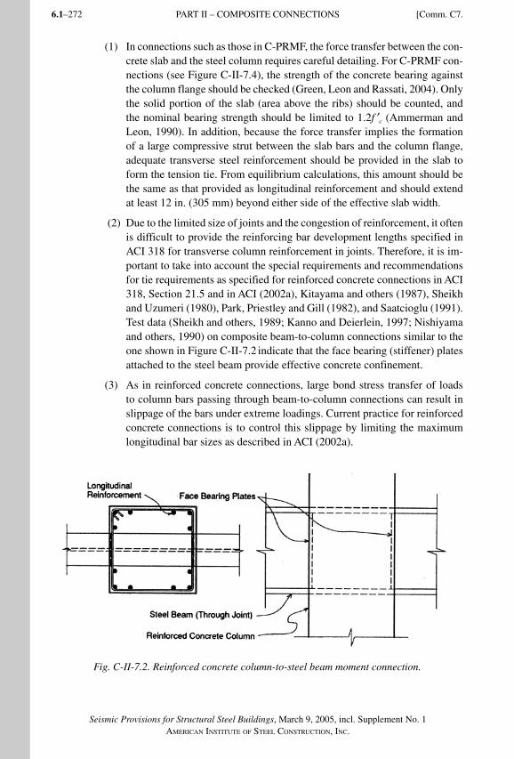
Seismic Provisions for Structural Steel Buildings, March 9, 2005, incl. Supplement No. 1AMERICAN INSTITUTE OF STEEL CONSTRUCTION, INC.
6.1–272
(1) In connections such as those in C-PRMF, the force transfer between the con-crete slab and the steel column requires careful detailing. For C-PRMF con-nections (see Figure C-II-7.4), the strength of the concrete bearing against the column flange should be checked (Green, Leon and Rassati, 2004). Only the solid portion of the slab (area above the ribs) should be counted, and the nominal bearing strength should be limited to 1.2f ′c (Ammerman and Leon, 1990). In addition, because the force transfer implies the formation of a large compressive strut between the slab bars and the column flange, adequate transverse steel reinforcement should be provided in the slab to form the tension tie. From equilibrium calculations, this amount should be the same as that provided as longitudinal reinforcement and should extend at least 12 in. (305 mm) beyond either side of the effective slab width.
(2) Due to the limited size of joints and the congestion of reinforcement, it often is difficult to provide the reinforcing bar development lengths specified in ACI 318 for transverse column reinforcement in joints. Therefore, it is im-portant to take into account the special requirements and recommendations for tie requirements as specified for reinforced concrete connections in ACI 318, Section 21.5 and in ACI (2002a), Kitayama and others (1987), Sheikh and Uzumeri (1980), Park, Priestley and Gill (1982), and Saatcioglu (1991). Test data (Sheikh and others, 1989; Kanno and Deierlein, 1997; Nishiyama and others, 1990) on composite beam-to-column connections similar to the one shown in Figure C-II-7.2 indicate that the face bearing (stiffener) plates attached to the steel beam provide effective concrete confinement.
(3) As in reinforced concrete connections, large bond stress transfer of loads to column bars passing through beam-to-column connections can result in slippage of the bars under extreme loadings. Current practice for reinforced concrete connections is to control this slippage by limiting the maximum longitudinal bar sizes as described in ACI (2002a).
Fig. C-II-7.2. Reinforced concrete column-to-steel beam moment connection.
PART II – COMPOSITE CONNECTIONS [Comm. C7.
SeismicProvComm2.indd 272SeismicProvComm2.indd 272 9/8/06 12:18:32 PM9/8/06 12:18:32 PMProcess BlackProcess Black
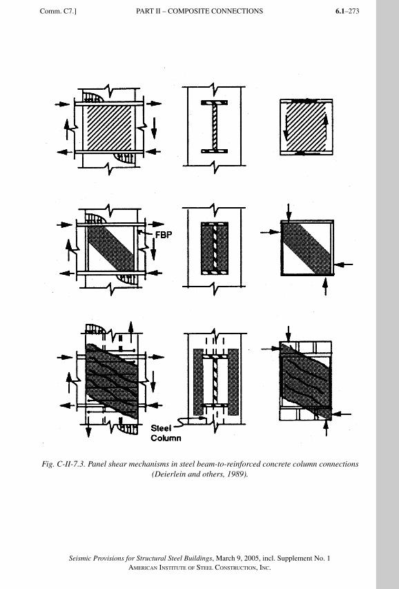
6.1–273
Seismic Provisions for Structural Steel Buildings, March 9, 2005, incl. Supplement No. 1AMERICAN INSTITUTE OF STEEL CONSTRUCTION, INC.
Fig. C-II-7.3. Panel shear mechanisms in steel beam-to-reinforced concrete column connections (Deierlein and others, 1989).
Comm. C7.] PART II – COMPOSITE CONNECTIONS
SeismicProvComm2.indd 273SeismicProvComm2.indd 273 9/8/06 12:18:33 PM9/8/06 12:18:33 PMProcess BlackProcess Black
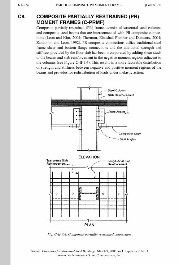
Seismic Provisions for Structural Steel Buildings, March 9, 2005, incl. Supplement No. 1AMERICAN INSTITUTE OF STEEL CONSTRUCTION, INC.
6.1–274
C8. COMPOSITE PARTIALLY RESTRAINED (PR) MOMENT FRAMES (C-PRMF)Composite partially restrained (PR) frames consist of structural steel columns and composite steel beams that are interconnected with PR composite connec-tions (Leon and Kim, 2004; Thermou, Elnashai, Plumier and Doneaux, 2004; Zandonini and Leon, 1992). PR composite connections utilize traditional steel frame shear and bottom flange connections and the additional strength and stiffness provided by the floor slab has been incorporated by adding shear studs to the beams and slab reinforcement in the negative moment regions adjacent to the columns (see Figure C-II-7.4). This results in a more favorable distribution of strength and stiffness between negative and positive moment regions of the beams and provides for redistribution of loads under inelastic action.
Fig. C-II-7.4. Composite partially restrained connection.
PART II – COMPOSITE PR MOMENT FRAMES [Comm. C8.
SeismicProvComm2.indd 274SeismicProvComm2.indd 274 9/8/06 12:18:33 PM9/8/06 12:18:33 PMProcess BlackProcess Black
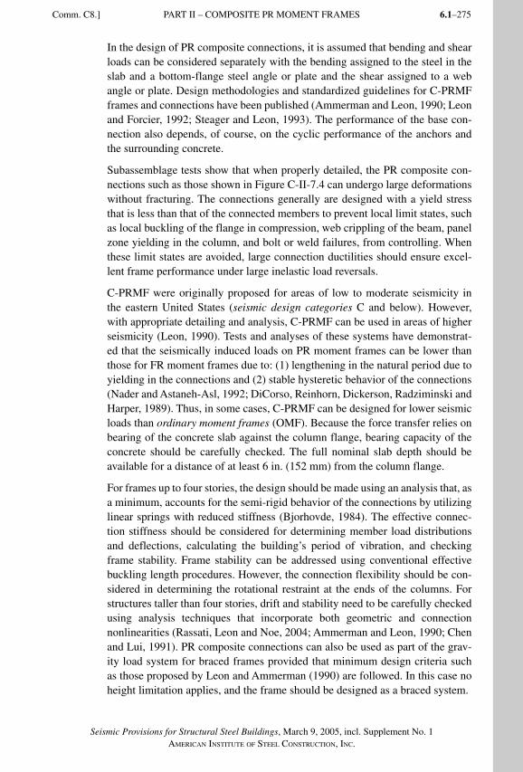
6.1–275
Seismic Provisions for Structural Steel Buildings, March 9, 2005, incl. Supplement No. 1AMERICAN INSTITUTE OF STEEL CONSTRUCTION, INC.
In the design of PR composite connections, it is assumed that bending and shear loads can be considered separately with the bending assigned to the steel in the slab and a bottom-flange steel angle or plate and the shear assigned to a web angle or plate. Design methodologies and standardized guidelines for C-PRMF frames and connections have been published (Ammerman and Leon, 1990; Leon and Forcier, 1992; Steager and Leon, 1993). The performance of the base con-nection also depends, of course, on the cyclic performance of the anchors and the surrounding concrete.
Subassemblage tests show that when properly detailed, the PR composite con-nections such as those shown in Figure C-II-7.4 can undergo large deformations without fracturing. The connections generally are designed with a yield stress that is less than that of the connected members to prevent local limit states, such as local buckling of the flange in compression, web crippling of the beam, panel zone yielding in the column, and bolt or weld failures, from controlling. When these limit states are avoided, large connection ductilities should ensure excel-lent frame performance under large inelastic load reversals.
C-PRMF were originally proposed for areas of low to moderate seismicity in the eastern United States (seismic design categories C and below). However, with appropriate detailing and analysis, C-PRMF can be used in areas of higher seismicity (Leon, 1990). Tests and analyses of these systems have demonstrat-ed that the seismically induced loads on PR moment frames can be lower than those for FR moment frames due to: (1) lengthening in the natural period due to yielding in the connections and (2) stable hysteretic behavior of the connections (Nader and Astaneh-Asl, 1992; DiCorso, Reinhorn, Dickerson, Radziminski and Harper, 1989). Thus, in some cases, C-PRMF can be designed for lower seismic loads than ordinary moment frames (OMF). Because the force transfer relies on bearing of the concrete slab against the column flange, bearing capacity of the concrete should be carefully checked. The full nominal slab depth should be available for a distance of at least 6 in. (152 mm) from the column flange.
For frames up to four stories, the design should be made using an analysis that, as a minimum, accounts for the semi-rigid behavior of the connections by utilizing linear springs with reduced stiffness (Bjorhovde, 1984). The effective connec-tion stiffness should be considered for determining member load distributions and deflections, calculating the building’s period of vibration, and checking frame stability. Frame stability can be addressed using conventional effective buckling length procedures. However, the connection flexibility should be con-sidered in determining the rotational restraint at the ends of the columns. For structures taller than four stories, drift and stability need to be carefully checked using analysis techniques that incorporate both geometric and connection nonlinearities (Rassati, Leon and Noe, 2004; Ammerman and Leon, 1990; Chen and Lui, 1991). PR composite connections can also be used as part of the grav-ity load system for braced frames provided that minimum design criteria such as those proposed by Leon and Ammerman (1990) are followed. In this case no height limitation applies, and the frame should be designed as a braced system.
Comm. C8.] PART II – COMPOSITE PR MOMENT FRAMES
SeismicProvComm2.indd 275SeismicProvComm2.indd 275 9/8/06 12:18:34 PM9/8/06 12:18:34 PMProcess BlackProcess Black
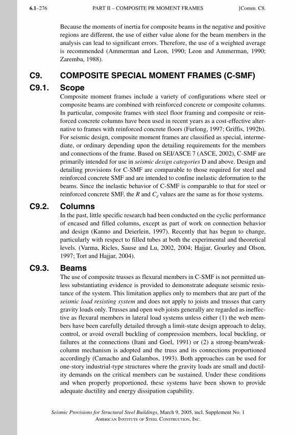
Seismic Provisions for Structural Steel Buildings, March 9, 2005, incl. Supplement No. 1AMERICAN INSTITUTE OF STEEL CONSTRUCTION, INC.
6.1–276
Because the moments of inertia for composite beams in the negative and positive regions are different, the use of either value alone for the beam members in the analysis can lead to significant errors. Therefore, the use of a weighted averageis recommended (Ammerman and Leon, 1990; Leon and Ammerman, 1990; Zaremba, 1988).
C9. COMPOSITE SPECIAL MOMENT FRAMES (C-SMF)
C9.1. ScopeComposite moment frames include a variety of configurations where steel or composite beams are combined with reinforced concrete or composite columns. In particular, composite frames with steel floor framing and composite or rein-forced concrete columns have been used in recent years as a cost-effective alter-native to frames with reinforced concrete floors (Furlong, 1997; Griffis, 1992b). For seismic design, composite moment frames are classified as special, interme-diate, or ordinary depending upon the detailing requirements for the members and connections of the frame. Based on SEI/ASCE 7 (ASCE, 2002), C-SMF are primarily intended for use in seismic design categories D and above. Design and detailing provisions for C-SMF are comparable to those required for steel and reinforced concrete SMF and are intended to confine inelastic deformation to the beams. Since the inelastic behavior of C-SMF is comparable to that for steel or reinforced concrete SMF, the R and Cd values are the same as for those systems.
C9.2. ColumnsIn the past, little specific research had been conducted on the cyclic performance of encased and filled columns, except as part of work on connection behavior and design (Kanno and Deierlein, 1997). Recently that has begun to change, particularly with respect to filled tubes at both the experimental and theoretical levels. (Varma, Ricles, Sause and Lu, 2002, 2004; Hajjar, Gourley and Olson, 1997; Tort and Hajjar, 2004).
C9.3. BeamsThe use of composite trusses as flexural members in C-SMF is not permitted un-less substantiating evidence is provided to demonstrate adequate seismic resis-tance of the system. This limitation applies only to members that are part of the seismic load resisting system and does not apply to joists and trusses that carry gravity loads only. Trusses and open web joists generally are regarded as ineffec-tive as flexural members in lateral load systems unless either (1) the web mem-bers have been carefully detailed through a limit-state design approach to delay, control, or avoid overall buckling of compression members, local buckling, or failures at the connections (Itani and Goel, 1991) or (2) a strong-beam/weak-column mechanism is adopted and the truss and its connections proportioned accordingly (Camacho and Galambos, 1993). Both approaches can be used for one-story industrial-type structures where the gravity loads are small and ductil-ity demands on the critical members can be sustained. Under these conditions and when properly proportioned, these systems have been shown to provide adequate ductility and energy dissipation capability.
PART II – COMPOSITE PR MOMENT FRAMES [Comm. C8.
SeismicProvComm2.indd 276SeismicProvComm2.indd 276 9/8/06 12:18:34 PM9/8/06 12:18:34 PMProcess BlackProcess Black
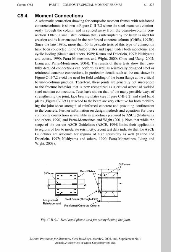
6.1–277
Seismic Provisions for Structural Steel Buildings, March 9, 2005, incl. Supplement No. 1AMERICAN INSTITUTE OF STEEL CONSTRUCTION, INC.
C9.4. Moment ConnectionsA schematic connection drawing for composite moment frames with reinforced concrete columns is shown in Figure C-II-7.2 where the steel beam runs continu-ously through the column and is spliced away from the beam-to-column con-nection. Often, a small steel column that is interrupted by the beam is used for erection and is later encased in the reinforced concrete column (Griffis, 1992b). Since the late 1980s, more than 60 large-scale tests of this type of connection have been conducted in the United States and Japan under both monotonic and cyclic loading (Sheikh and others, 1989; Kanno and Deierlein, 1997; Nishiyama and others, 1990; Parra-Montesinos and Wight, 2000; Chou and Uang, 2002; Liang and Parra-Montesinos, 2004). The results of these tests show that care-fully detailed connections can perform as well as seismically designed steel or reinforced concrete connections. In particular, details such as the one shown in Figure C-II-7.2 avoid the need for field welding of the beam flange at the critical beam-to-column junction. Therefore, these joints are generally not susceptible to the fracture behavior that is now recognized as a critical aspect of welded steel moment connections. Tests have shown that, of the many possible ways of strengthening the joint, face bearing plates (see Figure C-II-7.2) and steel band plates (Figure C-II-9.1) attached to the beam are very effective for both mobiliz-ing the joint shear strength of reinforced concrete and providing confinement to the concrete. Further information on design methods and equations for these composite connections is available in guidelines prepared by ASCE (Nishiyama and others, 1990) and Parra-Montesinos and Wight (2001). Note that while the scope of the current ASCE Guidelines (ASCE, 1994) limits their application to regions of low to moderate seismicity, recent test data indicate that the ASCE Guidelines are adequate for regions of high seismicity as well (Kanno and Deierlein, 1997; Nishiyama and others, 1990; Parra-Montesinos, Liang and Wight, 2003).
Fig. C-II-9.1. Steel band plates used for strengthening the joint.
Comm. C9.] PART II – COMPOSITE SPECIAL MOMENT FRAMES
SeismicProvComm2.indd 277SeismicProvComm2.indd 277 9/8/06 12:18:34 PM9/8/06 12:18:34 PMProcess BlackProcess Black
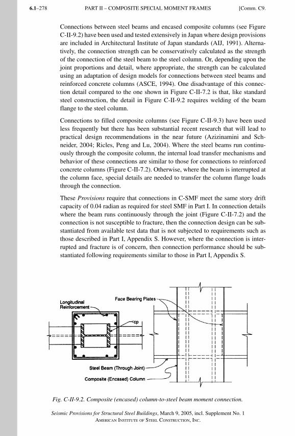
Seismic Provisions for Structural Steel Buildings, March 9, 2005, incl. Supplement No. 1AMERICAN INSTITUTE OF STEEL CONSTRUCTION, INC.
6.1–278
Connections between steel beams and encased composite columns (see Figure C-II-9.2) have been used and tested extensively in Japan where design provisions are included in Architectural Institute of Japan standards (AIJ, 1991). Alterna-tively, the connection strength can be conservatively calculated as the strength of the connection of the steel beam to the steel column. Or, depending upon the joint proportions and detail, where appropriate, the strength can be calculated using an adaptation of design models for connections between steel beams and reinforced concrete columns (ASCE, 1994). One disadvantage of this connec-tion detail compared to the one shown in Figure C-II-7.2 is that, like standard steel construction, the detail in Figure C-II-9.2 requires welding of the beam flange to the steel column.
Connections to filled composite columns (see Figure C-II-9.3) have been used less frequently but there has been substantial recent research that will lead to practical design recommendations in the near future (Azizinamini and Sch-neider, 2004; Ricles, Peng and Lu, 2004). Where the steel beams run continu-ously through the composite column, the internal load transfer mechanisms and behavior of these connections are similar to those for connections to reinforced concrete columns (Figure C-II-7.2). Otherwise, where the beam is interrupted at the column face, special details are needed to transfer the column flange loads through the connection.
These Provisions require that connections in C-SMF meet the same story drift capacity of 0.04 radian as required for steel SMF in Part I. In connection details where the beam runs continuously through the joint (Figure C-II-7.2) and the connection is not susceptible to fracture, then the connection design can be sub-stantiated from available test data that is not subjected to requirements such as those described in Part I, Appendix S. However, where the connection is inter-rupted and fracture is of concern, then connection performance should be sub-stantiated following requirements similar to those in Part I, Appendix S.
Fig. C-II-9.2. Composite (encased) column-to-steel beam moment connection.
PART II – COMPOSITE SPECIAL MOMENT FRAMES [Comm. C9.
SeismicProvComm2.indd 278SeismicProvComm2.indd 278 9/8/06 12:18:35 PM9/8/06 12:18:35 PMProcess BlackProcess Black
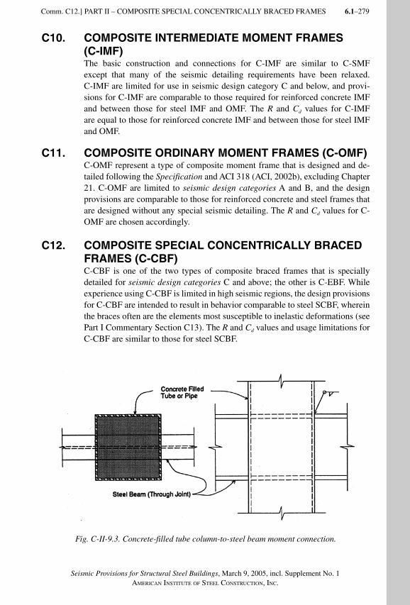
6.1–279
Seismic Provisions for Structural Steel Buildings, March 9, 2005, incl. Supplement No. 1AMERICAN INSTITUTE OF STEEL CONSTRUCTION, INC.
C10. COMPOSITE INTERMEDIATE MOMENT FRAMES (C-IMF)The basic construction and connections for C-IMF are similar to C-SMF except that many of the seismic detailing requirements have been relaxed. C-IMF are limited for use in seismic design category C and below, and provi-sions for C-IMF are comparable to those required for reinforced concrete IMF and between those for steel IMF and OMF. The R and Cd values for C-IMF are equal to those for reinforced concrete IMF and between those for steel IMF and OMF.
C11. COMPOSITE ORDINARY MOMENT FRAMES (C-OMF)C-OMF represent a type of composite moment frame that is designed and de-tailed following the Specification and ACI 318 (ACI, 2002b), excluding Chapter 21. C-OMF are limited to seismic design categories A and B, and the design provisions are comparable to those for reinforced concrete and steel frames that are designed without any special seismic detailing. The R and Cd values for C-OMF are chosen accordingly.
C12. COMPOSITE SPECIAL CONCENTRICALLY BRACED FRAMES (C-CBF)C-CBF is one of the two types of composite braced frames that is specially detailed for seismic design categories C and above; the other is C-EBF. While experience using C-CBF is limited in high seismic regions, the design provisions for C-CBF are intended to result in behavior comparable to steel SCBF, wherein the braces often are the elements most susceptible to inelastic deformations (see Part I Commentary Section C13). The R and Cd values and usage limitations for C-CBF are similar to those for steel SCBF.
Fig. C-II-9.3. Concrete-filled tube column-to-steel beam moment connection.
Comm. C12.] PART II – COMPOSITE SPECIAL CONCENTRICALLY BRACED FRAMES
SeismicProvComm2.indd 279SeismicProvComm2.indd 279 9/8/06 12:18:35 PM9/8/06 12:18:35 PMProcess BlackProcess Black
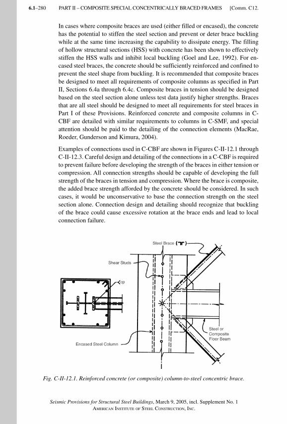
Seismic Provisions for Structural Steel Buildings, March 9, 2005, incl. Supplement No. 1AMERICAN INSTITUTE OF STEEL CONSTRUCTION, INC.
6.1–280
In cases where composite braces are used (either filled or encased), the concrete has the potential to stiffen the steel section and prevent or deter brace buckling while at the same time increasing the capability to dissipate energy. The filling of hollow structural sections (HSS) with concrete has been shown to effectively stiffen the HSS walls and inhibit local buckling (Goel and Lee, 1992). For en-cased steel braces, the concrete should be sufficiently reinforced and confined to prevent the steel shape from buckling. It is recommended that composite braces be designed to meet all requirements of composite columns as specified in Part II, Sections 6.4a through 6.4c. Composite braces in tension should be designed based on the steel section alone unless test data justify higher strengths. Braces that are all steel should be designed to meet all requirements for steel braces in Part I of these Provisions. Reinforced concrete and composite columns in C-CBF are detailed with similar requirements to columns in C-SMF, and special attention should be paid to the detailing of the connection elements (MacRae, Roeder, Gunderson and Kimura, 2004).
Examples of connections used in C-CBF are shown in Figures C-II-12.1 through C-II-12.3. Careful design and detailing of the connections in a C-CBF is required to prevent failure before developing the strength of the braces in either tension or compression. All connection strengths should be capable of developing the full strength of the braces in tension and compression. Where the brace is composite, the added brace strength afforded by the concrete should be considered. In such cases, it would be unconservative to base the connection strength on the steel section alone. Connection design and detailing should recognize that buckling of the brace could cause excessive rotation at the brace ends and lead to local connection failure.
Fig. C-II-12.1. Reinforced concrete (or composite) column-to-steel concentric brace.
PART II – COMPOSITE SPECIAL CONCENTRICALLY BRACED FRAMES [Comm. C12.
SeismicProvComm2.indd 280SeismicProvComm2.indd 280 9/8/06 12:18:36 PM9/8/06 12:18:36 PMProcess BlackProcess Black
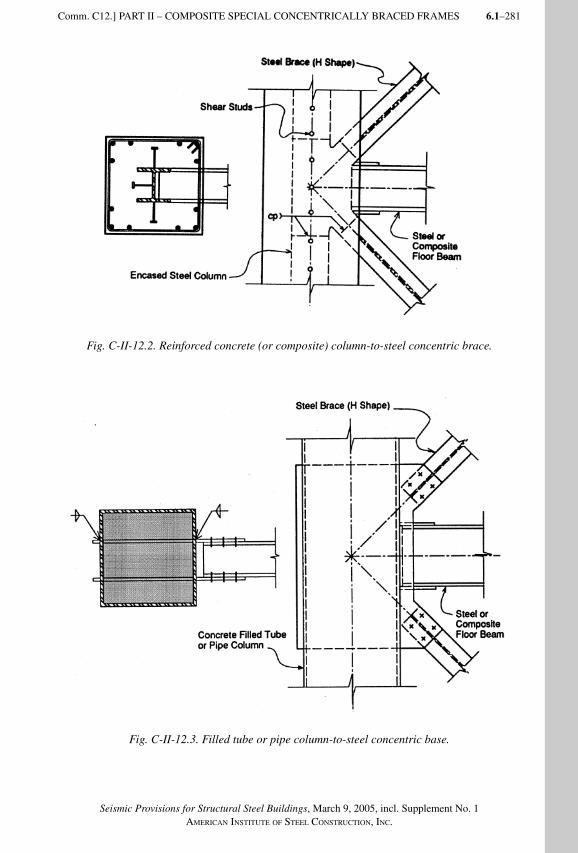
6.1–281
Seismic Provisions for Structural Steel Buildings, March 9, 2005, incl. Supplement No. 1AMERICAN INSTITUTE OF STEEL CONSTRUCTION, INC.
Fig. C-II-12.2. Reinforced concrete (or composite) column-to-steel concentric brace.
Fig. C-II-12.3. Filled tube or pipe column-to-steel concentric base.
Comm. C12.] PART II – COMPOSITE SPECIAL CONCENTRICALLY BRACED FRAMES
SeismicProvComm2.indd 281SeismicProvComm2.indd 281 9/8/06 12:18:36 PM9/8/06 12:18:36 PMProcess BlackProcess Black
Seismic Provisions for Structural Steel Buildings, March 9, 2005, incl. Supplement No. 1AMERICAN INSTITUTE OF STEEL CONSTRUCTION, INC.
6.1–282
C13. COMPOSITE ORDINARY BRACED FRAMES (C-OBF)Composite braced frames consisting of steel, composite and/or reinforced con-crete elements have been used in low- and high-rise buildings in regions of low and moderate seismicity. The C-OBF category is provided for systems without special seismic detailing that are used in seismic design categories A and B. Because significant inelastic load redistribution is not relied upon in the design, there is no distinction between frames where braces frame concentrically or ec-centrically into the beams and columns.
C14. COMPOSITE ECCENTRICALLY BRACED FRAMES (C-EBF)Structural steel EBF have been extensively tested and utilized in seismic regions and are recognized as providing excellent resistance and energy absorption for seismic loads (see Part I, Commentary Section C15). While there has been little use of C-EBF, the inelastic behavior of the critical steel link should be essentially the same as for steel EBF and inelastic deformations in the composite or rein-forced concrete columns should be minimal. Therefore, the R and Cd values and usage limitations for C-EBF are the same as those for steel EBF. As described below, careful design and detailing of the brace-to-column and link-to-column connections is essential to the performance of the system.
The basic requirements for C-EBF are the same as those for steel EBF with ad-ditional provisions for the design of composite or reinforced concrete columns and the composite connections. While the inelastic deformations of the columns should be small, as a conservative measure, detailing for the reinforced concrete and encased composite columns is based upon ACI 318, Chapter 21. In addition, where links are adjacent to the column, closely spaced hoop reinforcement is required similar to that used at hinge regions in reinforced concrete SMF. This requirement is in recognition of the large moments and load reversals imposed in the columns near the links.
Satisfactory behavior of C-EBF is dependent on making the braces and columns strong enough to remain essentially elastic under loads generated by inelastic deformations of the links. Since this requires an accurate calculation of the shear link nominal strength, it is important that the shear region of the link not be encased in concrete. Portions of the beam outside of the link are permitted to be encased since overstrength outside the link would not reduce the effectiveness of the system. Shear links are permitted to be composite with the floor or roof slab since the slab has a minimal effect on the nominal shear strength of the link. The additional strength provided by composite action with the slab is important to consider, however, for long links whose nominal strength is governed by flexural yielding at the ends of the links (Ricles and Popov, 1989).
In C-EBF where the link is not adjacent to the column, the concentric brace-to-column connections are similar to those shown for C-CBF (Figures C-II-12.1 through C-II-12.3). An example where the link is adjacent to the column is shown in Figure C-II-14.1. In this case, the link-to-column connection is similar
PART II – COMPOSITE ORDINARY BRACED FRAMES [Comm. C13.
SeismicProvComm2.indd 282SeismicProvComm2.indd 282 9/8/06 12:18:37 PM9/8/06 12:18:37 PMProcess BlackProcess Black
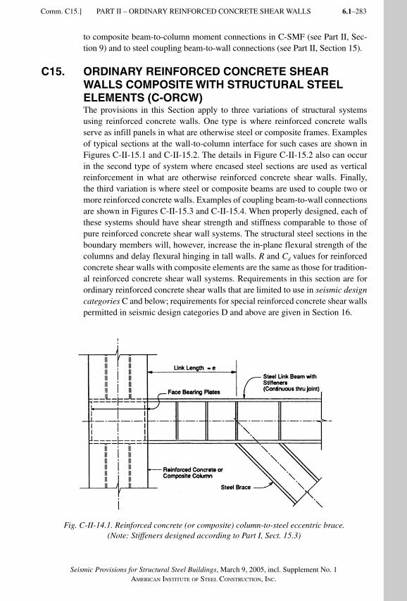
6.1–283
Seismic Provisions for Structural Steel Buildings, March 9, 2005, incl. Supplement No. 1AMERICAN INSTITUTE OF STEEL CONSTRUCTION, INC.
to composite beam-to-column moment connections in C-SMF (see Part II, Sec-tion 9) and to steel coupling beam-to-wall connections (see Part II, Section 15).
C15. ORDINARY REINFORCED CONCRETE SHEAR WALLS COMPOSITE WITH STRUCTURAL STEEL ELEMENTS (C-ORCW)The provisions in this Section apply to three variations of structural systems using reinforced concrete walls. One type is where reinforced concrete walls serve as infill panels in what are otherwise steel or composite frames. Examples of typical sections at the wall-to-column interface for such cases are shown in Figures C-II-15.1 and C-II-15.2. The details in Figure C-II-15.2 also can occur in the second type of system where encased steel sections are used as vertical reinforcement in what are otherwise reinforced concrete shear walls. Finally, the third variation is where steel or composite beams are used to couple two or more reinforced concrete walls. Examples of coupling beam-to-wall connections are shown in Figures C-II-15.3 and C-II-15.4. When properly designed, each of these systems should have shear strength and stiffness comparable to those of pure reinforced concrete shear wall systems. The structural steel sections in the boundary members will, however, increase the in-plane flexural strength of the columns and delay flexural hinging in tall walls. R and Cd values for reinforced concrete shear walls with composite elements are the same as those for tradition-al reinforced concrete shear wall systems. Requirements in this section are for ordinary reinforced concrete shear walls that are limited to use in seismic design categories C and below; requirements for special reinforced concrete shear walls permitted in seismic design categories D and above are given in Section 16.
Fig. C-II-14.1. Reinforced concrete (or composite) column-to-steel eccentric brace. (Note: Stiffeners designed according to Part I, Sect. 15.3)
Comm. C15.] PART II – ORDINARY REINFORCED CONCRETE SHEAR WALLS
SeismicProvComm2.indd 283SeismicProvComm2.indd 283 9/8/06 12:18:37 PM9/8/06 12:18:37 PMProcess BlackProcess Black
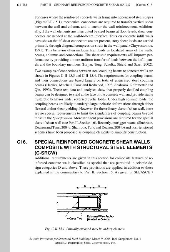
Seismic Provisions for Structural Steel Buildings, March 9, 2005, incl. Supplement No. 1AMERICAN INSTITUTE OF STEEL CONSTRUCTION, INC.
6.1–284
For cases where the reinforced concrete walls frame into nonencased steel shapes (Figure C-II-15.1), mechanical connectors are required to transfer vertical shear between the wall and column, and to anchor the wall reinforcement. Addition-ally, if the wall elements are interrupted by steel beams at floor levels, shear con-nectors are needed at the wall-to-beam interface. Tests on concrete infill walls have shown that if shear connectors are not present, story shear loads are carried primarily through diagonal compression struts in the wall panel (Chrysostomou, 1991). This behavior often includes high loads in localized areas of the walls, beams, columns and connections. The shear stud requirements will improve per-formance by providing a more uniform transfer of loads between the infill pan-els and the boundary members (Hajjar, Tong, Schultz, Shield and Saari, 2002).
Two examples of connections between steel coupling beams to concrete walls are shown in Figures C-II-15.3 and C-II-15.4. The requirements for coupling beams and their connections are based largely on tests of unencased steel coupling beams (Harries, Mitchell, Cook and Redwood, 1993; Shahrooz, Remmetter and Qin, 1993). These test data and analyses show that properly detailed coupling beams can be designed to yield at the face of the concrete wall and provide stable hysteretic behavior under reversed cyclic loads. Under high seismic loads, the coupling beams are likely to undergo large inelastic deformations through either flexural and/or shear yielding. However, for the ordinary class of shear wall, there are no special requirements to limit the slenderness of coupling beams beyond those in the Specification. More stringent provisions are required for the special class of shear wall (see Part II, Section 16). Recently, outrigger beams (Shahrooz, Deason and Tunc, 2004a; Shahrooz, Tunc and Deason, 2004b) and post-tensioned schemes have been proposed as coupling elements to simplify construction.
C16. SPECIAL REINFORCED CONCRETE SHEAR WALLS COMPOSITE WITH STRUCTURAL STEEL ELEMENTS (C-SRCW)Additional requirements are given in this section for composite features of re-inforced concrete walls classified as special that are permitted in seismic de-sign categories D and above. These provisions are applied in addition to those explained in the commentary to Part II, Section 15. As given in SEI/ASCE 7
Fig. C-II-15.1. Partially encased steel boundary element.
PART II – ORDINARY REINFORCED CONCRETE SHEAR WALLS [Comm. C15.
SeismicProvComm2.indd 284SeismicProvComm2.indd 284 9/8/06 12:18:38 PM9/8/06 12:18:38 PMProcess BlackProcess Black
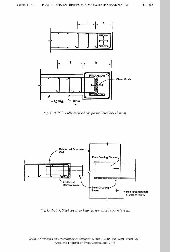
6.1–285
Seismic Provisions for Structural Steel Buildings, March 9, 2005, incl. Supplement No. 1AMERICAN INSTITUTE OF STEEL CONSTRUCTION, INC.
Fig. C-II-15.2. Fully encased composite boundary element.
Fig. C-II-15.3. Steel coupling beam to reinforced concrete wall.
Comm. C16.] PART II – SPECIAL REINFORCED CONCRETE SHEAR WALLS
SeismicProvComm2.indd 285SeismicProvComm2.indd 285 9/8/06 12:18:38 PM9/8/06 12:18:38 PMProcess BlackProcess Black
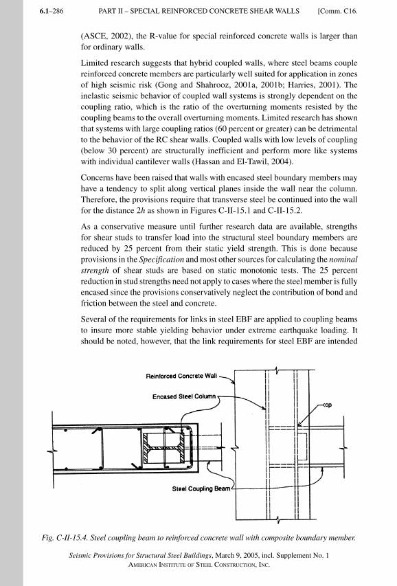
Seismic Provisions for Structural Steel Buildings, March 9, 2005, incl. Supplement No. 1AMERICAN INSTITUTE OF STEEL CONSTRUCTION, INC.
6.1–286
(ASCE, 2002), the R-value for special reinforced concrete walls is larger than for ordinary walls.
Limited research suggests that hybrid coupled walls, where steel beams couple reinforced concrete members are particularly well suited for application in zones of high seismic risk (Gong and Shahrooz, 2001a, 2001b; Harries, 2001). The inelastic seismic behavior of coupled wall systems is strongly dependent on the coupling ratio, which is the ratio of the overturning moments resisted by the coupling beams to the overall overturning moments. Limited research has shown that systems with large coupling ratios (60 percent or greater) can be detrimental to the behavior of the RC shear walls. Coupled walls with low levels of coupling (below 30 percent) are structurally inefficient and perform more like systems with individual cantilever walls (Hassan and El-Tawil, 2004).
Concerns have been raised that walls with encased steel boundary members may have a tendency to split along vertical planes inside the wall near the column. Therefore, the provisions require that transverse steel be continued into the wall for the distance 2h as shown in Figures C-II-15.1 and C-II-15.2.
As a conservative measure until further research data are available, strengths for shear studs to transfer load into the structural steel boundary members are reduced by 25 percent from their static yield strength. This is done because provisions in the Specification and most other sources for calculating the nominal strength of shear studs are based on static monotonic tests. The 25 percent reduction in stud strengths need not apply to cases where the steel member is fully encased since the provisions conservatively neglect the contribution of bond and friction between the steel and concrete.
Several of the requirements for links in steel EBF are applied to coupling beams to insure more stable yielding behavior under extreme earthquake loading. It should be noted, however, that the link requirements for steel EBF are intended
Fig. C-II-15.4. Steel coupling beam to reinforced concrete wall with composite boundary member.
PART II – SPECIAL REINFORCED CONCRETE SHEAR WALLS [Comm. C16.
SeismicProvComm2.indd 286SeismicProvComm2.indd 286 9/8/06 12:18:39 PM9/8/06 12:18:39 PMProcess BlackProcess Black
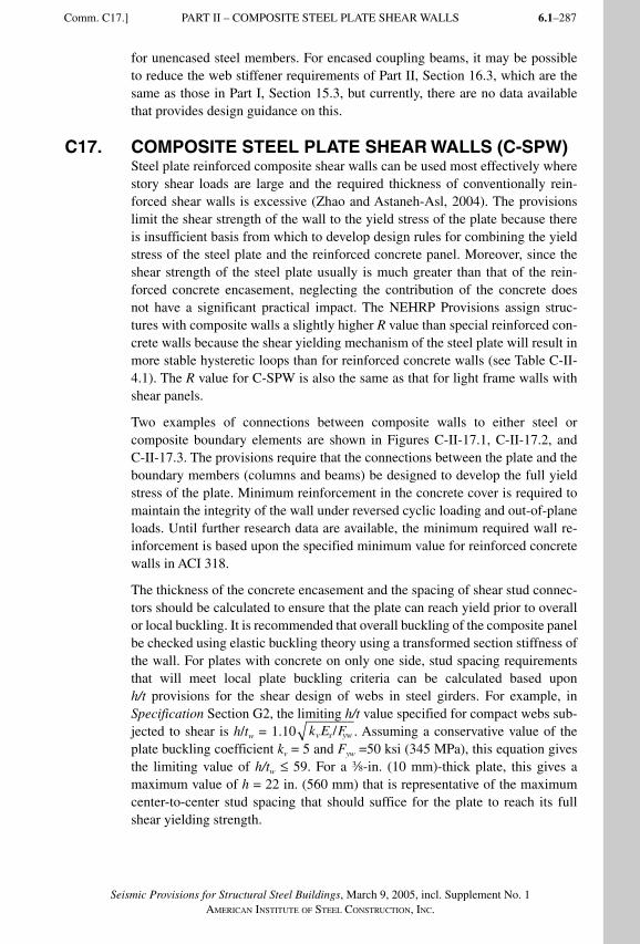
6.1–287
Seismic Provisions for Structural Steel Buildings, March 9, 2005, incl. Supplement No. 1AMERICAN INSTITUTE OF STEEL CONSTRUCTION, INC.
for unencased steel members. For encased coupling beams, it may be possible to reduce the web stiffener requirements of Part II, Section 16.3, which are the same as those in Part I, Section 15.3, but currently, there are no data available that provides design guidance on this.
C17. COMPOSITE STEEL PLATE SHEAR WALLS (C-SPW)Steel plate reinforced composite shear walls can be used most effectively where story shear loads are large and the required thickness of conventionally rein-forced shear walls is excessive (Zhao and Astaneh-Asl, 2004). The provisions limit the shear strength of the wall to the yield stress of the plate because there is insufficient basis from which to develop design rules for combining the yield stress of the steel plate and the reinforced concrete panel. Moreover, since the shear strength of the steel plate usually is much greater than that of the rein-forced concrete encasement, neglecting the contribution of the concrete does not have a significant practical impact. The NEHRP Provisions assign struc-tures with composite walls a slightly higher R value than special reinforced con-crete walls because the shear yielding mechanism of the steel plate will result in more stable hysteretic loops than for reinforced concrete walls (see Table C-II-4.1). The R value for C-SPW is also the same as that for light frame walls with shear panels.
Two examples of connections between composite walls to either steel or composite boundary elements are shown in Figures C-II-17.1, C-II-17.2, and C-II-17.3. The provisions require that the connections between the plate and the boundary members (columns and beams) be designed to develop the full yield stress of the plate. Minimum reinforcement in the concrete cover is required to maintain the integrity of the wall under reversed cyclic loading and out-of-plane loads. Until further research data are available, the minimum required wall re-inforcement is based upon the specified minimum value for reinforced concrete walls in ACI 318.
The thickness of the concrete encasement and the spacing of shear stud connec-tors should be calculated to ensure that the plate can reach yield prior to overall or local buckling. It is recommended that overall buckling of the composite panelbe checked using elastic buckling theory using a transformed section stiffness of the wall. For plates with concrete on only one side, stud spacing requirements that will meet local plate buckling criteria can be calculated based upon h/t provisions for the shear design of webs in steel girders. For example, in Specification Section G2, the limiting h/t value specified for compact webs sub-jected to shear is h/tw = 1.10 k E / F v s yw . Assuming a conservative value of the plate buckling coefficient kv = 5 and Fyw =50 ksi (345 MPa), this equation gives the limiting value of h/tw ≤ 59. For a a-in. (10 mm)-thick plate, this gives a maximum value of h = 22 in. (560 mm) that is representative of the maximum center-to-center stud spacing that should suffice for the plate to reach its full shear yielding strength.
Comm. C17.] PART II – COMPOSITE STEEL PLATE SHEAR WALLS
SeismicProvComm2.indd 287SeismicProvComm2.indd 287 9/8/06 12:18:40 PM9/8/06 12:18:40 PMProcess BlackProcess Black
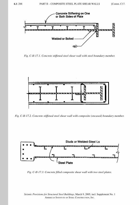
Seismic Provisions for Structural Steel Buildings, March 9, 2005, incl. Supplement No. 1AMERICAN INSTITUTE OF STEEL CONSTRUCTION, INC.
6.1–288
Fig. C-II-17.1. Concrete stiffened steel shear wall with steel boundary member.
Fig. C-II-17.2. Concrete stiffened steel shear wall with composite (encased) boundary member.
Fig. C-II-17.3. Concrete filled composite shear wall with two steel plates.
PART II – COMPOSITE STEEL PLATE SHEAR WALLS [Comm. C17.
SeismicProvComm2.indd 288SeismicProvComm2.indd 288 9/8/06 12:18:40 PM9/8/06 12:18:40 PMProcess BlackProcess Black
6.1–289
Seismic Provisions for Structural Steel Buildings, March 9, 2005, incl. Supplement No. 1AMERICAN INSTITUTE OF STEEL CONSTRUCTION, INC.
Careful consideration should be given to the shear and flexural strength of wall piers and of spandrels adjacent to openings. In particular, composite walls with large door openings may require structural steel boundary members attached to the steel plate around the openings.
C18. STRUCTURAL DESIGN DRAWINGS AND SPECIFICATIONS, SHOP DRAWINGS, AND ERECTION DRAWINGSStructural design drawings and specifications, shop drawings, and erection drawings for composite steel-concrete construction are basically similar to those given in Part I for all-steel structures. For the reinforced concrete portion of the work, in addition to the requirements in ACI 318 Section 1.2, attention is called to the ACI Detailing Manual (ACI, 1999a), with emphasis on Section 2.10, which contains requirements for seismic design of frames, joints, walls, diaphragms, and two-way slabs.
C19. QUALITY ASSURANCE PLANA quality assurance plan, similar to that required for all-steel structures shall be developed for a composite structure. For the reinforced concrete portion of the work, in addition to the requirements in ACI 318 Section 1.3 attention is called to the ACI Detailing Manual (ACI, 1999a), with emphasis on the provisions of ACI 121R (Quality Management Systems for Concrete Construction).
Comm. C19.] PART II – QUALITY ASSURANCE PLAN
SeismicProvComm2.indd 289SeismicProvComm2.indd 289 9/8/06 12:18:40 PM9/8/06 12:18:40 PMProcess BlackProcess Black

Seismic Provisions for Structural Steel Buildings, March 9, 2005, incl. Supplement No. 1AMERICAN INSTITUTE OF STEEL CONSTRUCTION, INC.
6.1–290
SeismicProvComm2.indd 290SeismicProvComm2.indd 290 9/8/06 12:18:41 PM9/8/06 12:18:41 PMProcess BlackProcess Black
6.1–291
Seismic Provisions for Structural Steel Buildings, March 9, 2005, incl. Supplement No. 1AMERICAN INSTITUTE OF STEEL CONSTRUCTION, INC.
REFERENCES
ACI (1999a), “Details and Detailing of Concrete Reinforcement,” ACI 315-99, SP-66 (04), American Concrete Institute, Farmington Hills, MI.
ACI (2002a), “Recommendations for the Design of Beam Column Joints in Monolithic Concrete Structures,” ACI 352-R-02, American Concrete Institute, Farmington Hills, MI.
ACI (2002b), Building Code Requirements for Structural Concrete, ACI 318-02, American Concrete Institute, Farmington Hills, MI.
Adany, S., Calado, L. and Dunai, L. (2000), “Experimental Studies on Cyclic Behavior Modes of Base Plate Connections,” Proceedings of the Third International Conference STESSA 2000, Montreal, Canada.
AIJ (1991), AIJ Standards for Structural Calculation of Steel Reinforced Concrete Structures (English translation of 1987 edition), Architectural Institute of Japan, Tokyo, Japan.
AISC (1997a), “K-area Advisory Statement,” Modern Steel Construction, February, American Institute of Steel Construction, Inc., Chicago, IL.
AISC (1997b), Seismic Provisions for Structural Steel Buildings, April 15, American Institute of Steel Construction, Inc., Chicago, IL.
AISC (2000a), Load and Resistance Factor Design Specification for Structural Steel Buildings, December 27, 1999, American Institute of Steel Construction, Inc., Chicago, IL.
AISC (2000b), Seismic Provisions for Structural Steel Buildings, Supplement No. 2, November 10, American Institute of Steel Construction, Inc., Chicago, IL.
AISC (2001a), Load and Resistance Factor Design Manual of Steel Construction, 3rd Ed., American Institute of Steel Construction, Inc., Chicago, IL.
AISC (2002), Seismic Provisions for Structural Steel Buildings, ANSI/AISC 341-02, May 21, American Institute of Steel Construction, Inc., Chicago, IL.
AISC (2005), Specification for Structural Steel Buildings, ANSI/AISC 360-05, March 9, American Institute of Steel Construction, Inc., Chicago, IL.
AISC (2005a), Prequalified Connections for Special and Intermediate Steel Moment Frames for Seismic Applications, ANSI/AISC 358-05, American Institute of Steel Construction, Inc., Chicago, IL.
AISC (2005b), Code of Standard Practice for Steel Buildings and Bridges, AISC 303-05, March 18, American Institute of Steel Construction, Inc., Chicago, IL.
AISI (2001), North American Specification for the Design of Cold-Formed Steel Structural Members, American Iron and Steel Institute, Washington, DC.
SeismicProvComm2.indd 291SeismicProvComm2.indd 291 9/8/06 12:18:41 PM9/8/06 12:18:41 PMProcess BlackProcess Black
Seismic Provisions for Structural Steel Buildings, March 9, 2005, incl. Supplement No. 1AMERICAN INSTITUTE OF STEEL CONSTRUCTION, INC.
6.1–292
Ammerman, D.J. and Leon, R.T. (1990), “Unbraced Frames with Semi-Rigid Connections,” Engineering Journal, AISC, Vol. 27, No. 1, 1st Quarter, pp. 12–21, Chicago, IL.
Arce, G. (2002), “Impact of Higher Strength Steels on Local Buckling and Overstrength in EBFs,” Master’s Thesis, Department of Civil Engineering, University of Texas at Austin, Austin, TX.
ASCE (1991a), Standard for the Structural Design of Composite Slabs, ANSI/ASCE 3-91, American Society of Civil Engineers, Reston, VA.
ASCE (1991b), Standard Practice for Construction and Inspection of Composite Slabs, ANSI/ASCE 9-91, American Society of Civil Engineers, Reston, VA.
ASCE (1994), “Guidelines for Design of Joints between Steel Beams and Reinforced Concrete Columns,” Journal of Structural Engineering, American Society of Civil Engineers, Vol. 120, No. 8, August, pp. 2330–2357, Reston, VA.
ASCE (2002), Min imum Design Loads for Buil dings and Other Stru ctures, SEI/ASCE 7-02, American Society of Civil Engineers, Reston, VA.
ASCE (2005), Min imum Design Loads for Buil dings and Other Stru ctures, SEI/ASCE 7-05, American Society of Civil Engineers, Reston, VA.
Aslani, F. and Goel, S.C. (1991), “Stitch Spacing and Local Buckling in Seismic Resistant Double Angle Bracing Members,” Journal of Structural Engineering, ASCE, Vol. 177, No. 8, August, Reston, VA.
Astaneh-Asl, A. (1998), “Seismic Behavior and Design of Gusset Plates for Braced Frames,” Steel Tips, Structural Steel Education Council, Moraga, CA.
Astaneh-Asl, A. and Ravat, S. (1997), “Cyclic Tests of Steel H-Piles,” Report No. UCB/CEE-Steel-97/01, Dept. of Civil and Env. Engrg., Univ. of California, Berkeley, CA.
Astaneh-Asl, A., Bergsma, G., and Shen, J.H. (1992), “Behavior and Design of Base Plates for Gravity, Wind and Seismic Loads,” Proceedings of the National Steel Construction Conference, AISC, Las Vegas, NV.
Astaneh-Asl, A., Bolt, B., McMullin, K., Donikian, R.R., Modjtahedi, D., and Cho, S-W (1994), “Seismic Performance of Steel Bridges During the 1994 Northridge Earthquake,” Report No. UCB/CEE-Steel-94/01, Dept. of Civil and Env. Engrg., Univ. of California, Berkeley, CA.
Astaneh-Asl, A., Goel, S.C., and Hanson, R.D. (1986), “Earthquake-Resistant Design of Double Angle Bracing,” Engineering Journal, AISC, Vol. 23, No. 4, 4th Quarter, Chicago, IL.
ATC (1992), Guidelines for Cyclic Seismic Testing of Components of Steel Structures, ATC-24, Applied Technology Council, Redwood City, CA.
AWS (2004), Structural Welding Code Steel, ANSI/AWS D1.1:2004, American Welding Society, Miami, FL.
REFERENCES
SeismicProvComm2.indd 292SeismicProvComm2.indd 292 9/8/06 12:18:41 PM9/8/06 12:18:41 PMProcess BlackProcess Black
6.1–293
Seismic Provisions for Structural Steel Buildings, March 9, 2005, incl. Supplement No. 1AMERICAN INSTITUTE OF STEEL CONSTRUCTION, INC.
Azizinamini, A. and Ghosh, S.K. (1996), “Steel Reinforced Concrete Structures in 1995 Hyogoken-Nanbu Earthquake,” Journal of Structural Engineering, Vol. 123, No. 8, August, pp. 986–990, ASCE, Reston, VA.
Azizinamini, A. and Schneider, S.P. (2004), “Moment Connections to Concrete-Filled Steel Tubes,” Journal of Structural Engineering, ASCE, Vol. 130, No. 2, pp. 213–222.
Bansal, J.P. (1971), “The Lateral Instability of Continuous Steel Beams,” CESRL Dissertation No. 71-1, University of Texas, Austin, TX.
Barsom, J.M. and Rolfe, S.T. (1999), Fracture and Fatigue Control in Structures: Applications of Fracture Mechanics, 3rd Ed., ASTM MNL41, American Society for Testing and Materials, West Conshohocken, PA.
Bartlett, F.M., Jelinek, J.J., Schmidt, B.J., Dexter, R.J., Graeser, M.D., and Galambos, T.V. (2001), Updating Standard Shape Material Properties Database for Design and Reliability, University of Western Ontario and University of Minnesota.
Basha, H.S. and Goel, S.C. (1994), Seismic Resistant Truss Moment Frames with Ductile Vierendeel Segment, Research Report No. UMCEE 94-29, The University of Michigan Department of Civil and Environmental Engineering, Ann Arbor, MI.
Becker, E.R. (1971), Panel Zone Effect on the Strength of Rigid Steel Frames, USCOE 001, University of Southern California Structural Mechanics Laboratory, Los Angeles, CA.
Berman, J. and Bruneau, M. (2003), “Plastic Analysis and Design of Steel Plate Shear Walls,” Journal of Structural Engineering, ASCE, Vol. 129, No. 11, November, pp. 1448–1456, Reston, VA.
Berman, J.W. and Bruneau, M. (2003a), “Experimental Investigation of Light-Guage Steel Plate Shear Walls for the Seismic Retrofit of Buildings,” Technical Report MCEER-03-001, Multidisciplinary Center for Earthquake Engineering Research, Buffalo, NY.
Berman, J.W. and Bruneau, M. (2003b), “Plastic Analysis and Design of Steel Plate Shear Walls,” Journal of Structural Engineering, ASCE, Vol. 129, No. 11, pp. 1148–1156, Reston, VA.
Berman, J.W. and Bruneau, M. (2004), “Steel Plate Shear Walls Are Not Plate Girders,” Engineering Journal, AISC, 3rd Quarter, Chicago, IL.
Bjorhovde, R. (1984), “Effects of End Restraint on Column Strength — Practical Applications,” Engineering Journal, AISC, Vol. 21, No. 1, 1st Quarter, pp. 1–13, Chicago, IL.
Bjorhovde, R., Colson, A., and Brozzetti, J. (1990), “Classification System for Beam-to-Column Connections,” Journal of Structural Engineering, ASCE, Vol. 116, No. 11, pp. 3059–3076.
Black, R.C., Wenger, W.A., and Popov, E.P. (1980), Inelastic Buckling of Steel Struts Under Cyclic Load Reversals, Report No. UCB/EERC-80-40, Earthquake Engineer ing Research Center, Berkeley, CA.
Blodgett, O.W. (2001), “Notes on Beam to Column Connections,” Steel Moment Frame Connection Advisory No. 3, SAC 95-01, SAC Joint Venture, Sacramento, CA.
REFERENCES
SeismicProvComm2.indd 293SeismicProvComm2.indd 293 9/8/06 12:18:41 PM9/8/06 12:18:41 PMProcess BlackProcess Black
Seismic Provisions for Structural Steel Buildings, March 9, 2005, incl. Supplement No. 1AMERICAN INSTITUTE OF STEEL CONSTRUCTION, INC.
6.1–294
Bondy, K.P. (1996), “A More Rational Approach to Capacity Design of Seismic Moment Frame Columns,” Earthquake Spectra, EERI, Volume 12, No. 3, August, Oakland, CA.
Boyd, P.F., Cofer, W.F., and McLean, D.I. (1995), “Seismic Performance of Steel-Encased Concrete Columns under Flexural Loading,” Structural Journal, ACI, Vol. 92, No. 3, pp. 355–364, May–June, Farmington Hills, MI.
Bruneau, M., Mahin, S.A., and Popov, E.P. (1987), Ultimate Behavior of Butt Welded Splices in Heavy Rolled Steel Sections, Report No. UCB/EERC-87/10, Earthquake Engineering Research Center, Berkeley, CA.
Burda, J.J. and Itani, A.M. (1999), “Studies of Seismic Behavior of Steel Base Plates,” Report No. CCEER 99-7, Center for Civil Engineering Earthquake Research, Dept. of Civil Engineering, Univ. of Nevada, Reno, Nevada.
Caccese, V., Elgaaly, M., and Chen, R. (1993), “Experimental Study of Thin Steel-Plate Shear Walls Under Cyclic Load,” Journal of Structural Engineering, ASCE, Vol. 119, No. 2, February, pp. 573–587, Reston, VA.
Camacho, D. and Galambos, T.V. (1993), Development of a Moment-Resisting One-Story Frame System for Seismic Resistance, Steel Joist Institute, Myrtle Beach, SC.
Cattan, J. (1995), Statistical Analysis of Charpy V-Notch Toughness for Steel Wide-Flange Structural Shapes, AISC, Chicago, IL.
Chen, W.F. and Lui, E.M. (1991), Stability Design of Steel Frames, CRC Press, Boca Raton, FL.
Cheng, J.J., Kulak, G.L., and Khoo, H.-A. (1998), “Strength of Slotted Tubular Tension Members,” Canadian Journal of Civil Engineering, Vol. 25, pp. 982–991.
Chi, B. and Uang, C.M. (2002), “Cyclic Response and Design Recommendations of Reduced Beam Section Moment Connections with Deep Columns,” Journal of Structural Engineering, ASCE, Vol. 128, No. 4, pp. 464–473, Reston, VA.
Chou, C.-C. and Uang, C.-M. (2002), “Cyclic Performance of a Type of Steel Beam to Steel-Encased Reinforced Concrete Column Moment Connections,” Journal of Constructional Steel Research, Vol. 58, pp. 637–663.
Chrysostomou, C.Z. (1991), “Effects of Degrading Infill Walls on the Nonlinear Seismic Response of Two-Dimensional Steel Frames,” Dissertation, Cornell University School of Civil and Environmental Engineering, Ithaca, NY.
Civjan, S.A. and Singh, P. (2003), “Behavior of Shear Studs Subjected to Fully Reversed Cyclic Loading,” Journal of Structural Engineering, ASCE, Vol. 129, No. 11, pp. 1466–1474, Reston,VA.
Clark, P., Aiken, I., Kasai, K., Ko, E., and Kimura, I. (1999), “Design Procedures for Buildings Incorporating Hysteretic Damping Devices,” Proceedings 68th Annual Convention, pp. 355–371, Structural Engineers Association of California, Sacramento, CA.
REFERENCES
SeismicProvComm2.indd 294SeismicProvComm2.indd 294 9/8/06 12:18:42 PM9/8/06 12:18:42 PMProcess BlackProcess Black
6.1–295
Seismic Provisions for Structural Steel Buildings, March 9, 2005, incl. Supplement No. 1AMERICAN INSTITUTE OF STEEL CONSTRUCTION, INC.
County of Los Angeles Department of Public Works (1996), County of Los Angeles Current Position on Design and Construction of Welded Moment Resisting Frame Systems (WMRF).
Deierlein, G.G. and Noguchi, H. (2004), “Overview of US-Japan Research on the Seismic Design of Composite Reinforced Concrete and Steel Moment Frame Structures,” Journal of Structural Engineering, ASCE, Vol. 130, No. 2, pp. 361–367, Reston, VA.
Deierlein, G.G., Sheikh, T.M., and Yura, J.A. (1989), “Part 2: Beam Column Moment Connections for Composite Frames,” Journal of Structural Engineering, ASCE, Vol. 115, No. 11, November, pp. 2877–2896, Reston, VA.
DeWolf, J.T. and Ricker, D.T. (1990), Column Base Plates, Steel Design Guide Series No. 1, AISC, Chicago, Illinois.
DeWolf, J.T. and Sarisley, E.F. (1980), “Column Base Plates with Axial Loads and Moments,” Journal of Structural Engineering, ASCE, Vol. 106, No. ST11, pp. 2167–2184, Reston, VA.
DiCorso, P.J., Reinhorn, A.M., Dickerson, J.R., Radziminski, J.B., and Harper, W.L. (1989), Response of Frames with Bolted Semi-Rigid Connections, Part I – Experimental Study on Analytical Predictions, Technical Report NCEER-89-0015, National Center for Earthquake Engineering Research, Buffalo, NY.
Drake, R. and Elkin, S.J. (1999), “Beam-Column Base Plate Design – LRFD Method,” Engineering Journal, AISC, Vol. 36, No. 1, 1st Quarter, pp. 29–38, Chicago, IL.
Driscoll, G.C. and Beedle, L.S. (1982), “Suggestions for Avoiding Beam-to-Column Web Connection Failure,” Engineering Journal, AISC, Vol. 19, No. 1, 1st Quarter, Chicago, IL.
Driver, R.G., Kulak, G.L., Kennedy, D.J.L., and Elwi, A.E. (1997), “Seismic Behavior of Steel Plate Shear Walls,” Structural Engineering Report No. 215, Department of Civil Engineering, University of Alberta, Edmonton, Alberta, Canada.
Dusicka, P. and Itani, A.M. (2002), “Behavior of Built-Up Shear Links Under Large Cyclic Deformations,” Proceedings of the 2002 Annual Meeting of the Structural Stability Research Council, Structural Stability Research Council, Gainesville, FL.
Easterling, W.S. and Porter M.L. (1994), “Steel Deck - Reinforced Concrete Diaphragms I & II,” Journal of Structural Engineering, ASCE, Vol. 120, No. 2, February, pp. 560–596, Reston, VA.
Ellingwood, B.R. and Corotis, R.B. (1991), “Load Combinations for Buildings Exposed to Fires,” Engineering Journal, AISC, Vol. 28, No. 1, 1st Quarter, pp. 37–44, Chicago, IL.
Elgaaly M. (1998), “Thin Steel Plate Shear Walls Behavior and Analysis,” Thin Walled Structures, Vol. 32, pp. 151–180.
Elgaaly, M., Caccese, V., and Du, C. (1993), “Postbuckling Behavior of Steel-Plate Shear Walls Under Cyclic Loads,” Journal of Structural Engineering, ASCE, Vol. 119, No. 2, Feb. 1993, pp. 588–605.
REFERENCES
SeismicProvComm2.indd 295SeismicProvComm2.indd 295 9/8/06 12:18:42 PM9/8/06 12:18:42 PMProcess BlackProcess Black
Seismic Provisions for Structural Steel Buildings, March 9, 2005, incl. Supplement No. 1AMERICAN INSTITUTE OF STEEL CONSTRUCTION, INC.
6.1–296
Elgaaly, M. and Lui, Y. (1997), “Analysis of Thin-Steel-Plate Shear Walls,” Journal of Structural Engineering, ASCE, Vol. 123, No. 11, November, pp. 1487–1496.
El-Tawil, S. and Deierlein, G.G. (1999), “Strength and Ductility of Encased Composite Columns,” Journal of Structural Engineering, ASCE, Vol. 125, No. 9, pp. 1009–1019.
El-Tawil, S., Mikesell, T.D., Vidarsson, E., and Kunnath, S.K. (1999), “Inelastic Behavior and Design of Steel Panel Zones,” Journal of Structural Engineering, ASCE, Vol. 125, No. 2, pp. 183–193, Reston, VA.
El-Tawil, S. (2000), “Panel Zone Yielding in Steel Moment Connections,” Engineering Journal, AISC, Vol. 37, No. 3, pp. 120–135, Chicago, IL.
El-Tawil, S. and Bracci, J. (2004), “Recent Findings from Phase V of the United States-Japan Cooperative Earthquake Research Program,” Journal of Structural Engineering, ASCE, Vol. 130, No. 2, pp. 155–156, Reston, VA.
El-Tayem, A. and Goel, S.C. (1986), “Effective Length Factor for the Design of X-Bracing Systems,” Engineering Journal, AISC, Vol. 23, No. 1, pp. 41–45, Chicago, IL.
Engelhardt, M.D. and Popov, E.P. (1989a), Behavior of Long Links in Ecce ntric ally Braced Frames, Report No. UCB/EERC-89/01, Earthquake Engineering Re search Center, Berkeley, CA.
Engelhardt, M.D. and Popov, E.P. (1989b), “On Design of Eccentrically Braced Frames,” Eart hquake Spectra, Vol. 5, No. 3, August, Earthquake Engineering Research Institute, Oakland, CA.
Englekirk, R.E. (1999), “Extant Panel Zone Design Procedures for Steel Frames Are Questioned,” Earthquake Spectra, EERI, Volume 15, No. 2, May, pp. 361–370, Oakland, CA.
Ermopoulos, J. and Stamatopoulos, G.N. (1996), “Mathematical Modeling of Column Base Plate Connections,” Journal of Constructional Steel Research, Vol. 36, No. 2, pp. 79–100.
ECS (1994), Eurocode 4, Design of Composite Steel and Concrete Structures, Part 1-1: General Rules and Rules for Buildings, European Committee for Standardization, Brussels, Belgium.
Fahmy, M., Stojadinovic, B., and Goel, S.C. (2000), “Seismic Behavior of Moment Resisting Steel Column Bases,” Research Report No. UMCEE 00-02, Dept. of Civil and Environmental Engineering, University of Michigan, Ann Arbor, MI.
Fahnestock, L.A., Sause, R., and Ricles, J.M. (2003), “Ductility Demands on Buckling-Restrained Braced Frames under Earthquake Loading,” Earthquake Engineering and Engineering Vibration, Vol. 2, No. 2, December, pp. 255–268.
FEMA (1994), NEHRP (National Earthquake Hazards Reduction Program) Recommended Provisions for Seismic Regulations for New Buildings, Federal Emergency Management Agency, Washington, DC.
REFERENCES
SeismicProvComm2.indd 296SeismicProvComm2.indd 296 9/8/06 12:18:42 PM9/8/06 12:18:42 PMProcess BlackProcess Black
6.1–297
Seismic Provisions for Structural Steel Buildings, March 9, 2005, incl. Supplement No. 1AMERICAN INSTITUTE OF STEEL CONSTRUCTION, INC.
FEMA (1995), Interim Guidelines: Evaluation, Repair, Modification and Design of Steel Moment Frames, FEMA 267 (SAC 95-02), Federal Emergency Management Agency, Washington, DC.
FEMA (1997a), NEHRP Recommended Provisions for Seismic Regulations for New Buildings and Other Structures, FEMA 302, Part 1—Provisions, Federal Emergency Management Agency, Washington, DC.
FEMA (1997b), Interim Guidelines Advisory No. 1—Supplement to FEMA 267, FEMA 267A (SAC 96-03), Federal Emergency Management Agency, Washington, DC.
FEMA (2000a), Recommended Seismic Design Criteria for New Steel Moment-Frame Buildings, FEMA 350, Federal Emergency Management Agency, Washington, DC.
FEMA (2000b), Recommended Specifications and Quality Assurance Guidelines for Steel Moment-Frame Construction for Seismic Applications, FEMA 353, Federal Emergency Management Agency, Washington, DC.
FEMA (2000d), State of the Art Report on Systems Performance of Steel Moment Frames Subject to Earthquake Ground Shaking, FEMA 355C, prepared by the SAC Joint Venture for the Federal Emergency Management Agency, Washington, DC.
FEMA (2000e), State of the Art Report on Connection Performance, FEMA 355D, prepared by the SAC Joint Venture for the Federal Emergency Management Agency, Washington, D.C.
FEMA (2000f), State of the Art Report on Performance Prediction and Evaluation of Steel Moment-Frame Buildings, FEMA 355F, prepared by the SAC Joint Venture for the Federal Emergency Management Agency, Washington, DC.
FEMA (2000g), NEHRP (National Earthquake Hazards Reduction Program) Recommended Provisions for Seismic Regulations for New Buildings, Federal Emergency Management Agency, Washington, DC.
FEMA (2000h), State of the Art Report on Welding and Inspection, Chapter 6, FEMA 355B, Federal Emergency Management Agency, Washington, DC.
FEMA (2003), NEHRP Recommended Provisions for Seismic Regulations for New Buildings and Other Structures, FEMA 450, Federal Emergency Management Agency, Washington, DC.
Fielding, D.J. and Huang, J.S. (1971), “Shear in Steel Beam-to-Column Conne ctions,” Welding Journal, AWS, Vol. 50, No. 7, Miami, FL.
Fisher, J.M. and West, M.A. (1990), Serviceability Design Considerations for Low-Rise Buildings, AISC, Chicago, IL.
Foutch, D.A. (1989), “Seismic Behavior of Eccentrically Braced Steel Buil ding,” Journal of Structural Engineering, ASCE, Vol. 115, No. 8, August, pp. 1857–1876, Reston, VA.
Furlong, R.W. (1997), “Composite Columns,” Composite Construction Design for Buildings, Chapter 4, ASCE/McGraw Hill, New York, NY.
REFERENCES
SeismicProvComm2.indd 297SeismicProvComm2.indd 297 9/8/06 12:18:42 PM9/8/06 12:18:42 PMProcess BlackProcess Black
Seismic Provisions for Structural Steel Buildings, March 9, 2005, incl. Supplement No. 1AMERICAN INSTITUTE OF STEEL CONSTRUCTION, INC.
6.1–298
Gilton, C.S. and Uang, C.M. (2002), “Cyclic Response and Design Recommendations of Weak-Axis Reduced Beam Section Moment Connections,” Journal of Structural Engineering, ASCE, Vol. 128, No. 4, April, Reston, VA.
Goel, S.C. and Lee, S. (1992), “A Fracture Criterion for Concrete-Filled Tubular Bracing Members Under Cyclic Loading,” Proceedings of the 1992 ASCE Structures Congress, ASCE, pp. 922–925, Reston, VA.
Goel, S.C. (1992), Recommendations for US/Japan Cooperative Research Program—Phase 5: Composite and Hybrid Structures, Report UMCEE 92-29, University of Michigan, Department of Civil and Environmental Engineering, Ann Arbor, MI.
Goel, S.C. (1992b), “Cyclic Post Buckling Behavior of Steel Bracing Members,” Stability and Ductility of Steel Structures under Cyclic Loading, pp. 75–104, CRC Press, Boca Raton, FL.
Goel, S.C. (1992c), “Earthquake Resistant Design of Ductile Braced Steel Structures,” Stability and Ductility of Steel Structures under Cyclic Loading, pp. 297–308, CRC Press, Boca Raton, FL.
Goel, S.C. (1993), Proceedings of a US/Japan Cooperative Research Program Workshop on Composite and Hybrid Structures, Report UMCEE 93, University of Michigan, Department of Civil and Environmental Engineering, Ann Arbor, MI.
Goel, S.C. and Itani, A. (1994a), “Seismic Behavior of Open Web Truss Moment Frames,” Journal of Structural Engineering, ASCE, Vol. 120, No. 6, June, pp. 1763–1780, Reston, VA.
Goel, S.C. and Itani, A. (1994b), “Seismic Resistant Special Truss Moment Frames,” Journal of Structural Engineering, ASCE, Vol. 120 No. 6, June, pp. 1781–1797, Reston, VA.
Goel, S.C. (2004), “United States-Japan Cooperative Earthquake Engineering Research Program on Composite and Hybrid Structures,” ASCE, Vol. 130, No. 2, pp. 157–158, Reston, VA.
Gong, B. and Shahrooz, B.M. (2001a), “Concrete-Steel Composite Coupling Beams – Part I: Component Testing,” Journal of Structural Engineering, ASCE, Vol. 127, No. 6, pp. 625–631, Reston, VA.
Gong, B. and Shahrooz, B.M. (2001b), “Concrete-Steel Composite Coupling Beams – Part II: Subassembly Testing and Design Verification,” Journal of Structural Engineering, ASCE, Vol. 127, No. 6, pp. 632–638, Reston, VA.
Green, T.P, Leon, R.T., and Rassati, G.A. (2004), “Bidirectional Tests on a Partially Restrained Beam-to-Column Connections,” Journal of Structural Engineering, ASCE, Vol. 130, No. 2, pp. 320–327, Reston, VA.
Griffis, L.G. (1992a), Load and Resistance Factor Design of W-Shapes Encased in Concrete, Design Guide Series 6, AISC, Chicago, IL.
Griffis, L.G. (1992b), “Composite Frame Construction,” Constructional Steel Design: An International Guide, Elsevier Science Publishers, pp. 523–553, London, England.
REFERENCES
SeismicProvComm2.indd 298SeismicProvComm2.indd 298 9/8/06 12:18:43 PM9/8/06 12:18:43 PMProcess BlackProcess Black
6.1–299
Seismic Provisions for Structural Steel Buildings, March 9, 2005, incl. Supplement No. 1AMERICAN INSTITUTE OF STEEL CONSTRUCTION, INC.
Gross, J.L., Engelhardt, M.D., Uang, C.-M., Kasai, K., and Iwankiw, N.R. (1999), Modification of Existing Welded Steel Moment Frame Connections for Seismic Resistance, Steel Design Guide Series 12, American Institute of Steel Construction, Inc., Chicago, IL.
Gupta, A. and Krawinkler, H. (1999), Prediction of Seismic Demands for SMRF’s with Ductile Connections and Elements, SAC/BD-99/06, SAC Joint Venture, Sacramento, CA.
Hajjar, J.F., Gourley, B.C., and Oslon, M.C. (1997), “A Cyclic Non-Linear Model for Concrete Filled Tubes. II: Verification,” Journal of Structural Engineering, ASCE, Vol. 123, No. 6, pp. 745–754, Reston, VA.
Hajjar, J.F., Tong, X., Schultz, A.E., Shield, C.K., and Saari, W.K. (2002), “Cyclic Behavior of Steel Frames with composite Reinforced Concrete Infill Walls,” Composite Construction in Steel and Concrete IV, Hajjar, J.F., Hosain, M., Easterling, W.S., and Shahrooz, B.M. (eds.), United Engineering Foundation, American Society of Civil Engineers, Reston, VA.
Harries, K., Mitchell, D., Cook, W.D., and Redwood, R.G. (1993), “Seismic Response of Steel Beams Coupling Concrete Walls,” Journal of Structural Engineering, ASCE, Vol. 119, No. 12, December, pp. 3611–3629, Reston, VA.
Harries, K.A. (2001), “Ductility and Deformability of Coupling Beams in Reinforced Concrete Coupled Walls,” Earthquake Spectra, EERI, Vol. 17, No. 3, pp. 457–478, Oakland, CA.
Hassan, M. and El-Tawil S. (2004), “Inelastic Dynamic Behavior of Hybrid Coupled Walls,” Journal of Structural Engineering, ASCE, Vol. 130, No. 2, pp. 285–296, Reston, VA.
Hassan, O. and Goel, S.C. (1991), Seismic Behavior and Design of Concentrically Braced Steel Structures Report UMCE 91-1, University of Michigan, Department of Civil and Environmental Engineering, Ann Arbor, MI.
Hjelmstad, K.D. and Popov, E.P. (1983), “Cyclic Behavior and Design of Link Beams,” Journal of Structural Engineering, Vol. 109, No. 10, October, ASCE, Reston, VA.
Hsieh, S.H. and Deierlein, G.G. (1991), “Nonlinear Analysis of Three-Dimensional Steel Frames with Semi-Rigid Connections,” Computers and Structures, Vol. 41, No. 5. pp. 995–1009.
Huckelbridge, A.A. and Clough, R.W. (1977), Earthquake Simulator Tests of Nine-Story Steel Frame with Columns Allowed to Uplift, Report No. UCB/EERC-77/23, Earthquake Engineering Research Center, Berkeley, CA.
ICC (2002), Supplement to the International Building Code, International Code Council, Birmingham, AL.
ICC (2003), International Building Code, International Code Council, Birmingham, AL.
ICC (2004), Acceptance Criteria for Steel Moment Frame Connection Systems, AC 129, ICC Evaluation Service, Inc., www.icc-es.org, Whittier, CA.
REFERENCES
SeismicProvComm2.indd 299SeismicProvComm2.indd 299 9/8/06 12:18:43 PM9/8/06 12:18:43 PMProcess BlackProcess Black
Seismic Provisions for Structural Steel Buildings, March 9, 2005, incl. Supplement No. 1AMERICAN INSTITUTE OF STEEL CONSTRUCTION, INC.
6.1–300
Itani, A. and Goel, S.C. (1991), Earthquake Resistant Design of Open Web Framing Systems, Research Report No. UMCE 91-21, University of Michigan, Department of Civil and Environmental Engineering, Ann Arbor, MI.
Jain, A., Goel, S.C., and Hanson, R.D. (1978), Hysteresis Behavior of Bracing Members and Seismic Response of Braced Frames with Different Proportions, Research Report No. UMEE78R3, University of Michigan, Department of Civil Engineering, Ann Arbor, MI.
Jaspart, J.P. and Vandegans, D. (1998), “Application of Component Method to Column Bases,” Journal of Constructional Steel Research, Vol. 48, pp. 89–106.
Kalyanaraman, V., Sridhara, B.N., and Thairani, V. (1998), “Core Loaded Earthquake Resistant Bracing Design,” Proceedings of the 2nd International Conference on Steel Construction, San Sebastian, Spain.
Kanno, R. and Deierlein, G.G. (1997), “Seismic Behavior of Composite (RCS) Beam-Column Joint Subassemblies,” Composite Construction III, ASCE, Reston, VA.
Kasai, K. and Popov, E.P. (1984), “On Seismic Design of Eccentrically Braced Steel Frames,” Proceedings of the 8th World Conference on Earthquake Engin eering, EERI, Vol. 5, pp. 387–394, San Francisco, CA.
Kasai, K. and Popov, E.P. (1986a), “General Behavior of WF Steel Shear Link Beams,” Journal of Structural Engineering, ASCE, Vol. 112, No. 2, February, Reston, VA.
Kasai, K. and Popov, E.P. (1986b), “Cyclic Web Buckling Control for Shear Link Beams,” Journal of Structural Engineering, ASCE, Vol. 112, No. 3, March, Reston, VA.
Kasai, K. and Popov, E.P. (1986c), A Study of Seismically Resistant Eccentrically Braced Frames, Report No. UCB/EERC-86/01, Earthquake Engineering Research Center, Berkeley, CA.
Kaufmann, E.J. and Fisher, J.W. (2001), Effect of Straightening Method on the Cyclic Behavior of K-area In Steel Rolled Shapes, ATLSS Center, Lehigh University, December.
Kaufmann, E.J., Metrovich, B.R., and Pense, A.W. (2001), Characterization of Cyclic Inelastic Strain Behavior On Properties of A572 Gr. 50 and A913 Gr 50 Rolled Sections, ATLSS Center, Lehigh University, August.
Kemp, A.R. (1986), “Factors Affecting the Rotation Capacity of Plastically Designed Members,” The Structural Engineer, Vol. 64B, No. 2, June, The Institution of Structural Engineers, London, England.
Khatib, I., Mahin, S.A., and Pister, K.S. (1988), Seismic Behavior of Concentrically Braced Steel Frames, Report No. UCB/EERC 88-01, Earthquake Engineering Research Center, Berkeley, CA.
Kitayama, K., Otani, S., and Aoyama, H. (1987), “Earthquake Resistant Design Criteria for Reinforced Concrete Interior Beam-Column Joints,” Proceedings of the Pacific Conference on Earthquake Engineering, Wairakei, New Zealand.
REFERENCES
SeismicProvComm2.indd 300SeismicProvComm2.indd 300 9/8/06 12:18:43 PM9/8/06 12:18:43 PMProcess BlackProcess Black
6.1–301
Seismic Provisions for Structural Steel Buildings, March 9, 2005, incl. Supplement No. 1AMERICAN INSTITUTE OF STEEL CONSTRUCTION, INC.
Korol, R.M. (1996), “Shear Lag in Slotted HSS Tension Members,” Canadian Journal of Civil Engineering, Vol. 23, pp. 1350–1354.
Krawinkler, H. (1978), “Shear in Beam-Column Joints in Seismic Design of Steel Fram es,” Engineering Journal, AISC, Vol. 15, No. 3, 3rd Quarter, Chicago, IL.
Krawinkler, H. (2001), private communication with Mark Saunders, November 2001.
Krawinkler, H. and Gupta, A. (1998), “Story Drift Demands for Steel Moment Frame Structures in Different Seismic Regions,” Proceedings of the 6th U.S. National Conference on Earthquake Engineering, Seattle, WA.
Kulak, G.L., Fisher, J.W., and Struik, J.H.A. (1987), Guide to Design Criteria for Bolted and Riveted Joints, 2nd Ed., John Wiley & Sons, New York, NY.
Lay, M.G. (1965), “Flange Local Buckling in Wide-Flange Shapes,” Journal of the Structural Division, ASCE, Vol. 91, No. 6, December, Reston, VA.
Lee, D., Cotton, S.C., Dexter, R.J., Hajjar, J.F., Ye, Y., and Ojard, S.D. (2002), Column Stiffener Detailing and Panel Zone Behavior of Steel Moment Frame Connections, University of Minnesota, June (Draft final).
Lee, D. and Goel, S.C. (2001), Seismic Behavior of Column Base Plate Connections Bending about Weak Axis, Research Report No. UMCEE 01-09, Dept. of Civil and Environmental Engineering, University of Michigan, Ann Arbor, MI.
Lee, H. and Goel, S.C. (1990), Seismic Behavior of Steel Built-up Box-Shaped Bracing Members, and Their Use in Strengthening Reinforced Concrete Frames, Report No. UMCE 90-7, University of Michigan, Ann Arbor, MI.
Lee, S. and Goel, S.C. (1987), Seismic Behavior of Hollow and Concrete-Filled Square Tubular Bracing Members, Report No. UMCE 87-11, University of Michigan, Department of Civil Engineering, Ann Arbor, MI.
Leon, R.T. (1990), “Semi-Rigid Composite Construction,” Journal of Constructional Steel Research, Vol. 15, No. 2, pp. 99–120, Elsevier Science Publishers, London, England.
Leon, R.T. (1994), “Composite Semi-Rigid Construction,” Engineering Journal, AISC, Vol. 31, No. 2, pp. 57–67, Chicago, IL.
Leon, R.T. and Ammerman, D.J. (1990), “Semi-Rigid Connection for Gravity Loads,” Engineering Journal, AISC, Vol. 27, No. 1, 1st Quarter, pp. 1–11, Chicago, IL.
Leon, R.T. and Forcier, G.P. (1992), “Parametric Study of Composite Frames,” Connections in Steel Structures II, Proceedings of the Second International Workshop on Connections in Steel Structures, AISC, pp. 152–159, Chicago, IL.
Leon, R.T. and Kim, D.H. (2004), “Seismic Performance of PR Frames in Zones of Infrequent Seismicity,” Proceedings of the 13th World Conference in Earthquake Engineering, Paper 2696, IAEE, Vancouver, BC, Canada.
Leon, R.T., Hajjar, J.F., and Shield, C.K. (1997), “The Effect of Composite Floor Slabs on the Behavior of Steel Moment-Resisting Frames in the Northridge Earthquake,” Composite Construction in Steel and Concrete III, ASCE, pp. 735–751, Reston, VA.
REFERENCES
SeismicProvComm2.indd 301SeismicProvComm2.indd 301 9/8/06 12:18:43 PM9/8/06 12:18:43 PMProcess BlackProcess Black
Seismic Provisions for Structural Steel Buildings, March 9, 2005, incl. Supplement No. 1AMERICAN INSTITUTE OF STEEL CONSTRUCTION, INC.
6.1–302
Leon, R.T., Hoffman, J., and Staeger, T. (1996), Design of Partially-Restrained Composite Connections, Steel Design Guide No. 8, AISC, Chicago, IL.
Liang, X. and Parra-Montesinos, G. (2004), “Seismic Behavior of RCS Beam-Column-SlabSubassemblies and Frame Systems,” Journal of Structural Engineering, ASCE, Vol. 130, No. 2, pp. 310–319, Reston, VA.
Libby, J.R. (1981), “Eccentrically Braced Frame Construction—A Case History,” Engineering Journal, AISC, Vol. 18, No. 4, 4th Quarter, Chicago, IL.
Liu, J. (2003), “Examination of Expected Yield and Tensile Strength Ratios,” Draft Addendum Report, AISC, Chicago, IL.
Liu, Z. and Goel, S.C. (1987), Investigation of Concrete Filled Steel Tubes under Cyclic Bending and Buckling, UMCE Report 87-3, University of Michigan, Ann Arbor, MI.
Liu, Z. and Goel, S.C. (1988), “Cyclic Load Behavior of Concrete-Filled Tubular Braces,” Journal of the Structural Division, ASCE, Vol. 114, No. 7, Reston, VA.
Lopez, W., Gwie, D.S., Lauck, T.W., and Saunders, C.M. (2004), “UC Berkeley Stanley Hall – Structural Design and Experimental Verification of a Buckling-Restrained Braced Frame System,” Engineering Journal, AISC, Vol. 41, No. 4, 4th Quarter, Chicago, IL.
Lubell, A.S., Prion, H.G.L., Ventura, C.E., and Rezai, M. (2000), “Unstiffened Steel Plate Shear Wall Performance under Cyclic Loading,” Journal of Structural Engineering, ASCE, Vol. 126, No.4, April, pp. 453–460, Reston, VA.
MacRae, G., Roeder, C.W., Gunderson, C., and Kimura, Y. (2004), “Brace-Beam-Column Connections for Concentrically Braced Frames with Concrete Filled Tube Columns,” Journal of Structural Engineering, ASCE, Vol. 130, No. 2, pp. 233–243, Reston, VA.
Malley, J.O. and Popov, E.P. (1984), “Shear Links in Eccentrically Braced Frames,” Journal of Structural Engineering, ASCE, Vol. 110, No. 9, September, Reston, VA.
McDaniel, C.C., Uang, C.M., and Seible, F. (2002), “Cyclic Testing of Built-Up Steel Shear Links for the New Bay Bridge,” Journal of Structural Engineering, ASCE, Vol. 129, No. 6, pp. 801–809, Reston, VA.
McMullin, K.M. and Astaneh-Asl, A. (1994), “Cyclical Behavior of Welded Steel Shear Studs,” Structures Congress XII, ASCE, pp. 1024–1029.
Meng, R.L. and Murray, T.M. (1997), “Seismic Performance of Bolted End-Plate Moment Connections,” Proceedings of the National Steel Construction Conference, AISC, Chicago, IL.
Merovich, A.T., Nicoletti, J.P., and Hartle, E. (1982), “Eccentric Bracing in Tall Buildings,” Journal of the Structural Division, ASCE, Vol. 108, No. 9, September, Reston, VA.
Midorikawa, M., Hasegawa, T., Mukai, A., Nishiyama, I., Fukuta, T., and Yamanouchi, H. (1997), “Damage Investigation of Steel Buildings in Specific Areas Observed from the 1995 Hyogoken-Nambu Earthquake,” Proceedings of U.S.–Japan Workshop on Steel Fracture Issues, San Francisco, CA.
REFERENCES
SeismicProvComm2.indd 302SeismicProvComm2.indd 302 9/8/06 12:18:44 PM9/8/06 12:18:44 PMProcess BlackProcess Black
6.1–303
Seismic Provisions for Structural Steel Buildings, March 9, 2005, incl. Supplement No. 1AMERICAN INSTITUTE OF STEEL CONSTRUCTION, INC.
Murray, T.M. and Shoemaker, W.L. (2002), Flush and Extended Multiple-Row Moment End-Plate Connections, Steel Design Guide Series No. 16, AISC, Chicago, IL.
Nader, M.N. and Astaneh-Asl, A. (1992), “Seismic Design Concepts for Semi-Rigid Frames,” Proceedings of the 1992 ASCE Structures Congress, ASCE, pp. 971–975, New York, NY.
Nakashima, M., Kanao, I., and Liu, D. (2002). “Lateral Instability and Lateral Bracing of Steel Beams Subjected to Cyclic Loading,” Journal of Structural Engineering, ASCE, Vol. 128, No. 10, October, pp. 1308–1316.
Nishiyama, I., Hasegawa, T., and Yamanouchi, H. (1990), “Strength and Deformation Capacity of Reinforced Concrete Column to Steel Beam Joint Panels,” Building Research Institute Report 71, Ministry of Construction, Tsukuba, Japan.
Northridge Reconnaissance Team (1996), “Northridge Earthquake of January 17, 1994,” Reconnaissance Report (Supplement C-2 to Volume 11), EERI, pp. 25–47, Oakland, CA.
Okazaki, T. (2004), “Seismic Performance of Link-to-Column Connections in Steel Eccentrically Braced Frames,” Ph.D. Dissertation, Department of Civil Engineering, University of Texas at Austin, Austin, TX.
Okazaki, T., Arce, G., Ryu, H., and Engelhardt, M.D. (2004a), “Recent Research on Link Performance in Steel Eccentrically Braced Frames,” Proceedings, 13th World Conference on Earthquake Engineering, August 1–6, 2004, Vancouver, BC, Canada.
Okazaki, T., Engelhardt, M.D., Nakashima, M., and Suita, K. (2004b), “Experimental Study on Link-to-Column Connections in Steel Eccentrically Braced Frames,” Proceedings, 13th World Conference on Earthquake Engineering, August 1–6, 2004, Vancouver, BC, Canada.
Park, R., Priestley, M.J.N., and Gill, W.D. (1982), “Ductility of Square Confined Concrete Columns,” Journal of the Structural Division, ASCE, Vol. 108, No. ST4, April, pp. 929–950, Reston, VA.
Parra-Montesinos, G. and Wight, J.K. (2000), “Seismic Response of Exterior RC Column-to-Steel Beam Connections,” Journal of Structural Engineering, ASCE, Vol. 126, No. 10, pp. 1113–1121, Reston, VA.
Parra-Montesinos, G. and Wight, J.K. (2001), “Modeling Shear Behavior of Hybrid RCS Beam-Column Connections,” Journal of Structural Engineering, ASCE, Vol. 127, No. 1, pp. 3–11.
Parra-Montesinos, G., Liang, X., and Wight, J.K. (2003), “Towards Deformation-Based Capacity Design of RCS Beam-Column Connections,” Engineering Structures, Vol. 25, No. 5, pp. 681–690.
Picard, A. and Beaulieu, D. (1985), “Behavior of a Simple Column Base Connection,” Canadian Journal of Civil Engineering, Vol. 12, pp. 126–136.
Popov, E.P. (1980), “Seismic Behavior of Structural Assemblages,” Journal of the Structural Division, ASCE, Vol. 106, No. ST7, July, pp. 1451–1474, Reston, VA.
REFERENCES
SeismicProvComm2.indd 303SeismicProvComm2.indd 303 9/8/06 12:18:44 PM9/8/06 12:18:44 PMProcess BlackProcess Black
Seismic Provisions for Structural Steel Buildings, March 9, 2005, incl. Supplement No. 1AMERICAN INSTITUTE OF STEEL CONSTRUCTION, INC.
6.1–304
Popov, E.P. and Engelhardt, M.D. (1988), “Seismic Eccentrically Braced Frames,” Journal of Constructional Steel Research, Vol. 10, pp. 321–354.
Popov, E.P. and Stephen, R.M. (1972), Cyclic Loading of Full-Size Steel Connec tions, Bulletin No. 21, American Iron and Steel Institute, Washington, DC.
Popov, E.P. and Stephen, R.M. (1977), “Tensile Capacity of Partial Penetration Welds,” Journal of the Structural Division, ASCE, Vol. 103, No. ST9, September, Reston, VA.
Popov, E.P., Blondet, M., Stepanov, L., and Stojadinovic, B. (1996), “Full-Scale Beam-to-Column Connection Tests,” University of California Department of Civil Engineering, Berkeley, CA.
Popov, E.P., Engelhardt, M.D., and Ricles, J.M. (1989), “Eccentrically Brace Frames: U. S. Practice,” Engineering Journal, AISC, Vol.26, No. 2, 2nd Quarter, pp. 66–80, Chicago, IL.
Rassati, G.A., Leon R.T., and Noe, S. (2004), “Component Modeling of Partially Restrained Composite Joints under Cyclic and Dynamic Loading,” Journal of Structural Engineering, ASCE, Vol. 130, No. 2, pp. 343–351, Reston, VA.
RCSC (2004), Specification for Structural Joints Using ASTM A325 or A490 Bolts, Research Council on Structural Connections, Chicago, IL.
Reina, P. and Normile, D. (1997), “Fully Braced for Seismic Survival,” Engineering News-Record, July 21, pp. 34–36, The McGraw Hill Companies, New York, NY.
Rezai, M. (1999), “Seismic Behavior of Steel Plate Shear Walls by Shake Table Testing,” Ph.D. Dissertation, University of British Columbia, Vancouver, BC, Canada.
Richards, P. and Uang, C.M. (2003), “Development of Testing Protocol for Short Links in Eccentrically Braced Frames,” Report No. SSRP-2003/08, Department of Structural Engineering, University of California at San Diego, San Diego, CA.
Richards, P. (2004), “Cyclic Stability and Capacity Design of Steel Eccentrically Braced Frames,” Ph.D. Dissertation, University of California, San Diego, CA.
Richards, P., Uang, C.M., Okazaki, T., and Engelhardt, M.D. (2004), “Impact of Recent Research Findings on Eccentrically Braced Frame Design,” Proceedings, 2004 SEAOC Convention, August 25–28, 2004, Monterey, CA.
Ricles, J.M. and Popov, E.P. (1987a), Dynamic Analysis of Seismically Resistant Eccentrically Braced Frames, Report No. UCB/EERC-87/107, Earthquake Enginee ring Research Center, Berkeley, CA.
Ricles, J.M. and Popov, E.P. (1987b), Experiments on EBFs with Composite Floors, Report No. UCB/EERC-87/06, Earthquake Engineering Research Center, Berkeley, CA.
Ricles, J.M. and Popov, E.P. (1989), “Composite Action in Eccentricity Braced Frames,” Journal of Structural Engineering, ASCE, Vol. 115, No. 8, August, pp. 2046–2066, Reston, VA.
Ricles, J.M., Peng, S.W., and Lu, L.W. (2004), “Seismic Behavior of Composite Concrete Filled Steel Tube Column-Wide Flange Beam Moment Connections,” Journal of Structural Engineering, ASCE, Vol. 130, No. 2, pp. 223–232, Reston, VA.
REFERENCES
SeismicProvComm2.indd 304SeismicProvComm2.indd 304 9/8/06 12:18:44 PM9/8/06 12:18:44 PMProcess BlackProcess Black
6.1–305
Seismic Provisions for Structural Steel Buildings, March 9, 2005, incl. Supplement No. 1AMERICAN INSTITUTE OF STEEL CONSTRUCTION, INC.
Ricles, J.M., Zhang, X., Lu, L.W., and Fisher, J. (2004), “Development of Seismic Guidelines for Deep Column Steel Moment Connections,” ATLSS Report No. 04-13, Lehigh University, Bethlehem, PA.
Roberts, T.M. and Sabouri-Ghomi, S. (1992), “Hysteretic Characteristics of Unstiffened Perforated Steel Plate Shear Walls,” Thin Walled Structures, Vol. 14, pp. 139–151.
Roeder, C.W. (1987), Inelastic Dynamic Analysis of Two Eight-Story Moment Frames, Structural Engineers Association of Washington, Seattle, WA.
Roeder, C.W. and Foutch, D.F. (1996), “Experimental Results for Seismic Resistant Steel Moment Frame Connections,” Journal of Structural Engineering, ASCE, Vol. 122, No. 6, June, Reston, VA.
Roeder, C.W. and Popov, E.P. (1978), “Eccentrically Braced Frames for Earth quakes,” Journal of the Structural Division, ASCE, Vol. 104, No. 3, March, Reston, VA.
Saari, W.K., Hajjar, J.F., Schultz, A. E., and Shield, C.K. (2004), “Behavior of Shear Studs in Steel Frames with Reinforced Concrete Infill Walls,” Journal of Constructional Steel Research, Vol. 60, pp. 1453–1480.
Saatcioglu, M. (1991), Deformability of Steel Columns, ACI 127.5, American Concrete Institute, Detroit, MI.
Sabelli, R., Mahin, S., and Chang, C. (2003), “Seismic Demands on Steel Braced Frame Buildings with Buckling-Restrained Braces,” Engineering Structures, Vol. 25, pp. 655–666.
Sabouri-Ghomi, S. and Roberts, T.M. (1992), “Nonlinear Dynamic Analysis of Steel Plate Shear Walls Including Shear and Bending Deformations,” Engineering Structures, AISC, Vol. 14, No. 3, pp. 309–317.
SAC (1996), Technical Report: Experimental Investigations of Beam-Column Subassemblages SAC95-09, SAC Joint Venture, Sacramento, CA.
SAC (1997), “Protocol for Fabrication, Inspection, Testing, and Documentation of Beam-Column Connection Tests and Other Specimens,” SAC/BD-97/02 Version 1.1, SAC Joint Venture, Sacramento, CA.
SAC (2000), “Loading Histories for Seismic Performance Testing of SMRF Components and Assemblies,” SAC/BD-00/10, SAC Joint Venture, Sacramento, CA.
Sato, K. and Kamagata, S. (1988), “Aseismic Behavior of Steel Column Base,” Proceedings of the Ninth World Conference on Earthquake Engineering, Tokyo, Japan.
Sawyer, H.A. (1961), “Post-Elastic Behavior of Wide-Flange Steel Beams,” Journal of the Structural Division, ASCE, Vol. 87, No. ST8, December, Reston, VA.
Schneider, S.P. (1998), “Axially Loaded Concrete-Filled Tubes,” Journal of Structural Engineering, ASCE, Vol. 124, No. 10, pp. 1125–1138, Reston, VA.
Schneider, S.P., Roeder, C.W., and Carpenter, J.E. (1991), Seismic Performance of Weak-Column Strong-Beam Steel Moment Resisting Frames, University of Washington Department of Civil Engineering, Seattle, WA.
REFERENCES
SeismicProvComm2.indd 305SeismicProvComm2.indd 305 9/8/06 12:18:44 PM9/8/06 12:18:44 PMProcess BlackProcess Black
Seismic Provisions for Structural Steel Buildings, March 9, 2005, incl. Supplement No. 1AMERICAN INSTITUTE OF STEEL CONSTRUCTION, INC.
6.1–306
SDI (2001a), Design Manual for Composite Decks, Form Decks and Roof Decks, No. 30, Steel Deck Institute, Fox River Grove, IL.
SDI (2001b), Standard Practice Details (SPD2), Steel Deck Institute, Fox River Grove, IL.
SDI (2004), Diaphragm Design Manual, 3rd Edition, No. DDMO3, Steel Deck Institute, Fox River Grove, IL.
Shahrooz, B.M, Deason, J.T., and Tunc, G. (2004a), “Outrigger Beam-Wall Connections. I: Component Testing and Development of a Design Model,” Journal of Structural Engineering, ASCE, Vol. 130, No. 2, pp. 253–261, Reston, VA.
Shahrooz, B.M, Tunc, G., and Deason, J.T. (2004b), “Outrigger Beam-Wall Connections. II: Subassembly Testing and Further Modeling Enhancements,” Journal of Structural Engineering, ASCE, Vol. 130, No. 2, pp. 262–270.
Shahrooz, B.M., Remmetter, M.E., and Qin, F. (1993), “Seismic Design and Performance of Composite Coupled Walls,” Journal of Structural Engineering, ASCE, Vol. 119, No. 11, November, pp. 3291–3309, Reston, VA.
Sheikh, S.A. and Uzumeri, S.M. (1980), “Strength and Ductility of Tied Columns,” Journal of the Structural Division, ASCE, Vol. 106, No. ST5, February, pp. 1079–1102, Reston, VA.
Sheikh, T.M., Deierlein, G.G., Yura, J.A., and Jirsa, J.O. (1989), “Part 1: Beam Column Moment Connections for Composite Frames,” Journal of Structural Engineering, ASCE, Vol. 115, No. 11, November, pp. 2859–2876, Reston, VA.
SIE (1999a), “Tests of Nippon Steel Corporation Unbonded Braces,” Report to Ove Arup & Partners, Seismic Isolation Engineering, CA.
SIE (1999b), “Report on Pre-Prototype Tests of Yielding Braces,” Seismic Isolation Engineering, CA.
Slutter, R. (1981), “Tests of Panel Zone Behavior in Beam Column Connectio ns,” Report No. 200.81.403.1, Lehigh University, Bethlehem, PA.
Spacone, E. and El-Tawil, S. (2004), “State-of-the-Art in Nonlinear Analysis of Composite Systems,” Journal of Structural Engineering, ASCE, Vol. 130, No. 2, pp. 159–168, Reston, VA.
Steager, A. and Leon, R.T. (1993), Partially Restrained Composite Connections, AISC, Chicago, IL.
Stojadinovic, B., Spacone, E., Goel, S.C., and Kwon, M. (1998), “Influence of Semi-Rigid Column Base Models on the Response of Steel MRF Buildings,” Proceedings of the Sixth U.S. National Conference on Earthquake Engineering, EERI, Seattle, WA.
Tang, X. and Goel, S.C. (1987), Seismic Analysis and Design Considerations of Braced Steel Structures, Report UMCE 87-4, University of Michigan, Department of Civil and Environmental Engineering, Ann Arbor, MI.
Tang, X. and Goel, S.C. (1989), “Brace Fractures and Analysis of Phase I Structure,” Journal of Structural Engineering, ASCE, Vol. 115, No. 8, August, pp. 1960–1976, Reston, VA.
REFERENCES
SeismicProvComm2.indd 306SeismicProvComm2.indd 306 9/8/06 12:18:44 PM9/8/06 12:18:44 PMProcess BlackProcess Black
6.1–307
Seismic Provisions for Structural Steel Buildings, March 9, 2005, incl. Supplement No. 1AMERICAN INSTITUTE OF STEEL CONSTRUCTION, INC.
Targowski, R., Lamblin, D., and Guerlement, G. (1993), “Base Plate Column Connection under Bending: Experimental and Numerical Study,” Journal of Constructional Steel Research, Vol. 27, pp. 37–54.
Thambiratnam, D. and Paramasivam, P. (1986), “Base Plates under Axial Loads and Moments,” Journal of Structural Engineering, ASCE, Vol. 112, No. 5, pp. 1166–1181, Reston, VA.
Thermou, G.E., Elnashai, A.S., Plumier, A., and Doneaux, C. (2004), “Seismic Design and Performance of Composite Frames,” Journal of Constructional Steel Research, Vol. 60, pp. 31–57.
Thorburn, L.J., Kulak, G.L., and Montgomery, C.J. (1983), “Analysis of Steel Plate Shear Walls,” Structural Engineering Report No. 107, Department of Civil Engineering, University of Alberta, Edmonton, Alberta, Canada.
Timler, P.A. and Kulak, G.L. (1983), “Experimental Study of Steel Plate Shear Walls,” Structural Engineering Report No. 114, Department of Civil Engineering, University of Alberta, Edmonton, Alberta, Canada.
Tort, C. and Hajjar, J.F. (2004), “Damage Assessment of Rectangular Concrete-Filled Steel Tubes for Performance-Based Design,” Earthquake Spectra, EERI, Vol. 20, No. 4, pp. 1317–1348, Oakland, CA.
Tremblay, R. (2000), “Influence of Brace Slenderness on the Seismic Response of Concentrically Braced Steel Frames,” Behaviour of Steel Structures in Seismic Areas - Stessa 2000: Proceedings of the Third International Conference, August 21–24, 2000, F.M. Mazzolani and R. Tremblay, (eds.), pp. 527–534, Montreal, Canada.
Tremblay, R. (2001), “Seismic Behavior and Design of Concentrically Braced Steel Frames,” Engineering Journal, AISC, Vol. 38, No. 3, Chicago, IL.
Tremblay, R. (2003), “Achieving a Stable Inelastic Seismic Response for Multi-Story Concentrically Braced Steel Frames,” Engineering Journal, AISC, Vol. 40, No. 2, Chicago, IL.
Tremblay, R., Degrange, G., and Blouin, J. (1999), “Seismic Rehabilitation of a Four-Storey Building with a Stiffened Bracing System,” Proc. 8th Can. Conf. on Earthquake Engrg., Canadian Association for Earthquake Engineering, pp. 549–554, Vancouver, BC, Canada.
Tremblay, R., Tchebotarev, N., and Filiatrault, A. (1997), “Seismic Performance of RBS Connections for Steel Moment Resisting Frames: Influence of Loading Rate and Floor Slab,” Proceedings, STESSA ’97, Kyoto, Japan.
Tromposch, E.W. and Kulak, G.L. (1987), “Cyclic and Static Behaviour of Thin Panel Steel Plate Shear Walls,” Structural Engineering Report No. 145, Department of Civil Engineering, University of Alberta, Edmonton, Alberta, Canada.
Tsai, K.-C., Weng, Y.-T., Lin, M.-L., Chen, C.-H., Lai, J.-W., and Hsiao, P.-C. (2003), “Pseudo Dynamic Tests of a Full-Scale CFT/BRB Composite Frame: Displacement Based Seismic Design and Response Evaluations,” Proceedings of the International Workshop on Steel and Concrete Composite Construction (IWSCCC-2003), Report No. NCREE-03-026, National Center for Research in Earthquake Engineering, pp. 165–176, Taipei, Taiwan.
REFERENCES
SeismicProvComm2.indd 307SeismicProvComm2.indd 307 9/8/06 12:18:45 PM9/8/06 12:18:45 PMProcess BlackProcess Black
Seismic Provisions for Structural Steel Buildings, March 9, 2005, incl. Supplement No. 1AMERICAN INSTITUTE OF STEEL CONSTRUCTION, INC.
6.1–308
Uang, C.M. and Chi, B. (2001), Effect of Straightening Method on the Cyclic Behavior of k Area in Steel Rolled Shapes, Report No. SSRP-2001/05, University of California, San Diego, CA, May.
Uang, C.M. and Fan, C.C. (2001), “Cyclic Stability Criteria for Steel Moment Connections with Reduced Beam Section,” Journal of Structural Engineering, ASCE, Vol. 127, No. 9, September, Reston, VA.
Uang, C.M. and Nakashima, M. (2003), “Steel Buckling-Restrained Frames,” Earthquake Engineering: Recent Advances and Applications, Chapter 16, Y. Bozorgnia and V.V. Bertero, (eds.) CRC Press, Boca Raton, FL.
Varma, A.H., Ricles, J.M., Sause, R., and Lu, L.W. (2002), “Experimental Behavior of High Strength Square Concrete Filled Tube Columns,” Journal of Structural Engineering, ASCE, Vol. 128, No. 3, pp. 309–318, Chicago, IL.
Varma, A.H., Ricles, J.M., Sause, R., and Lu, L.W. (2004), “Seismic Behavior and Design of High Strength Square Concrete Filled Tube Beam Columns,” Journal of Structural Engineering, ASCE, Vol. 130, No. 2, pp. 169–179, Reston, VA.
Viest, I.M., Colaco, J.P., Furlong, R.W., Griffis, L.G., Leon, R.T., and Wyllie, L.A., Jr. (1997), Composite Construction: Design for Buildings, McGraw-Hill/ASCE, Reston, VA.
Wada, A., Connor, J., Kawai, H., Iwata, M., and Watanabe, A. (1994), “Damage Tolerant Structure,” ATC-15-4 Proceedings of Fifth US—Japan Workshop on the Improvement of Building Structural Design and Construction Practices, pp. 27–39, Applied Technology Council, Redwood City, CA.
Wada, A., Saeki, E., Takeuchi, T., and Watanabe, A. (1998), “Development of Unbonded Brace,” Nippon Steel’s Unbonded Braces (promotional document), pp. 1–16, Nippon Steel Corporation Building Construction and Urban Development Division, Tokyo, Japan.
Wallace, B.J. and Krawinkler, H. (1985), Small-Scale Model Experimentation on Steel Assemblies John A. Blume Earthquake Engineering Center Report No. 75, Stanford University, Department of Civil Engineering, Palo Alto, CA.
Watanabe, A., Hitomi Y., Saeki, E., Wada, A., and Fujimoto, M. (1988), “Properties of Brace Encased in Buckling-Restraining Concrete and Steel Tube,” Proceedings of Ninth World Conference on Earthquake Engineering, Vol. IV, pp. 719–724, Japan Association for Earthquake Disaster Prevention, Tokyo-Kyoto, Japan.
Whittaker, A.S., Uang, C.-M., and Bertero, V.V. (1987), Earthquake Simul ation Tests and Associated Studies of a 0.3—Scale Model of a Six-Story Eccen tric ally Braced Steel Structure, Report no. UBC/EERC-87/02, Earthquake Engineering Research Center, Berke ley, CA.
Xu, P. and Goel, S.C. (1990), Behavior of Double Channel Bracing Members Under Large Cyclic Deformations, Report no. UMCE 90-1, University of Michigan, Department of Civil Engineering, Ann Arbor, MI.
Yamanouchi, H., Nishiyama, I., and Kobayashi, J. (1998), “Development and Usage of Composite and Hybrid Building Structure in Japan,” ACI SP-174, pp. 151–174.
REFERENCES
SeismicProvComm2.indd 308SeismicProvComm2.indd 308 9/8/06 12:18:45 PM9/8/06 12:18:45 PMProcess BlackProcess Black
6.1–309
Seismic Provisions for Structural Steel Buildings, March 9, 2005, incl. Supplement No. 1AMERICAN INSTITUTE OF STEEL CONSTRUCTION, INC.
Yang, F. and Mahin, S. (2005), “Limiting Net Section Fracture in Slotted Tube Braces,” Steel TIPS Report, Structural Steel Education Council, Moraga, CA.
Zandonini, R. and Leon, R.T. (1992), “Composite Connections,” Constructional Steel Design: An International Guide, pp. 501–522, Elsevier Science Publishers, London, England.
Zaremba, C.J. (1988), “Strength of Steel Frames Using Partial Composite Girders,” Journal of Structural Engineering, ASCE, Vol. 114, No. 8, August, pp. 1741–1760, Reston, VA.
Zhao, Q. and Astaneh-Asl, A. (2004), “Cyclic Behavior of Traditional and Innovative Composite Shear Walls,” Journal of Structural Engineering, ASCE, Vol. 130, No. 2, pp. 271–284.
REFERENCES
SeismicProvComm2.indd 309SeismicProvComm2.indd 309 9/8/06 12:18:45 PM9/8/06 12:18:45 PMProcess BlackProcess Black

Seismic Provisions for Structural Steel Buildings, March 9, 2005, incl. Supplement No. 1AMERICAN INSTITUTE OF STEEL CONSTRUCTION, INC.
6.1–310
SeismicProvComm2.indd 308SeismicProvComm2.indd 308 9/8/06 12:18:45 PM9/8/06 12:18:45 PMProcess BlackProcess Black