Embed Size (px)
Citation preview

AIS-380 FUEL FLOW ADAPTER
P/N: 833811-00
INSTALLATION MANUAL
MANUAL P/N: M833811-00
REV B
Shadin Avionics
6831 Oxford Street
St. Louis Park, MN 55426
USA
Sales: (800) 328-0584
Customer Service: (800) 388-2849
www.shadin.com

M833811-00 Shadin Avionics
INSTALLATION MANUAL AIS-380 FUEL FLOW ADAPTER
Rev: B P/N 833811-00 Page: 2 of 20
Shadin Avionics 6831 Oxford Street St. Louis Park, MN 55426 USA
REVISION LOG
REV DATE APP’D CHANGE CVS
Ver
– 5/9/2013 RJW Baseline Release 2
A 6/14/2013 ERN: 1306/004 Sections for accuracy and incomplete system description added 3
B 11/24/2014 ERN: 1411/002 Added DC Fuel Flow Installation Application 4

M833811-00 Shadin Avionics
INSTALLATION MANUAL AIS-380 FUEL FLOW ADAPTER
Rev: B P/N 833811-00 Page: 3 of 20
Shadin Avionics 6831 Oxford Street St. Louis Park, MN 55426 USA
Table of Contents
REVISION LOG 2
1 OVERVIEW 4
2 INSTALLATION 11
3 CONFIGURATION TOOL 12
4 ENVIRONMENTAL QUALIFICATION FORM (EQF) 19
5 INSTALLATION DRAWINGS AND INSTALL KIT PARTS LIST 20
M833811-00 Shadin Avionics
INSTALLATION MANUAL AIS-380 FUEL FLOW ADAPTER
Rev: B P/N 833811-00 Page: 4 of 20
Shadin Avionics 6831 Oxford Street St. Louis Park, MN 55426 USA
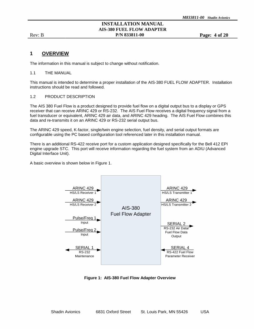
1 OVERVIEW The information in this manual is subject to change without notification. 1.1 THE MANUAL This manual is intended to determine a proper installation of the AIS-380 FUEL FLOW ADAPTER. Installation instructions should be read and followed. 1.2 PRODUCT DESCRIPTION The AIS 380 Fuel Flow is a product designed to provide fuel flow on a digital output bus to a display or GPS receiver that can receive ARINC 429 or RS-232. The AIS Fuel Flow receives a digital frequency signal from a fuel transducer or equivalent, ARINC 429 air data, and ARINC 429 heading. The AIS Fuel Flow combines this data and re-transmits it on an ARINC 429 or RS-232 serial output bus. The ARINC 429 speed, K-factor, single/twin engine selection, fuel density, and serial output formats are configurable using the PC based configuration tool referenced later in this installation manual. There is an additional RS-422 receive port for a custom application designed specifically for the Bell 412 EPI engine upgrade STC. This port will receive information regarding the fuel system from an ADIU (Advanced Digital Interface Unit).
A basic overview is shown below in Figure 1.
AIS-380
Fuel Flow Adapter
ARINC 429HS/LS Receiver 1
ARINC 429HS/LS Receiver 2
ARINC 429HS/LS Transmitter 1
ARINC 429HS/LS Transmitter 2
SERIAL 1RS-232
Maintenance
SERIAL 2RS-232 Air Data/
Fuel Flow Data
Output
SERIAL 4RS-422 Fuel Flow
Parameter Receiver
Pulse/Freq 1Input
Pulse/Freq 2Input
Figure 1: AIS-380 Fuel Flow Adapter Overview

M833811-00 Shadin Avionics
INSTALLATION MANUAL AIS-380 FUEL FLOW ADAPTER
Rev: B P/N 833811-00 Page: 5 of 20
Shadin Avionics 6831 Oxford Street St. Louis Park, MN 55426 USA
The features which are applicable to all standard installations are listed below:
Two +12 VDC power supplies are available for powering fuel flow transducers
ARINC inputs are echoed to the ARINC outputs
ARINC speed (high or low) is configurable. Each ARINC channel input and output speed is matched when configured, e.g. ARINC channel 1 input channel set for high speed results in ARINC channel 1 output set for high speed.
Fuel Flow labels 244 (Total Fuel Flow) and 347 (Left and Right independent Fuel Flow based on SDI) are generated and output at an 8 Hz rate when configured for normal fuel flow format
Specific features for the Bell 412 EPI Installation:
Fuel Flow labels 351 (Left Fuel Flow) and 352 (Right Fuel Flow) are generated and output at an 8 Hz rate when configured for Bell fuel flow format
The AIS-380 accepts Bell serial fuel flow parameters on Serial 4 RS-422 port

M833811-00 Shadin Avionics
INSTALLATION MANUAL AIS-380 FUEL FLOW ADAPTER
Rev: B P/N 833811-00 Page: 6 of 20
Shadin Avionics 6831 Oxford Street St. Louis Park, MN 55426 USA
1.3 SPECIFICATIONS
Physical Specifications
Dimensions: 1.57H x 6.90L x 4.24W (inches)
Weight: 0.7 lbs.
Electrical and Functional
Power Supply Voltage: +28VDC Nominal
Supply Current: 100mA at 28VDC
Environmental RTCA/DO-160F
Categories: [A4X]BBB[R(B,B1) U2(F, F1)]XXXXXXZ[BXX]AZ[CC][RR]M[XXJ33]XXAX
Operating Temperature: -40 to +70 C
Operating Altitude: Up to 42,000 ft.
Storage Temperature: -55 to +85 C
In-Flight loss of Cooling: Equipment can run indefinitely with no cooling
Regulatory: TSO-C44c INCOMPLETE SYSTEM
Software: DO-178B Level C
MIL-HDBK-217 MTBF: Greater than 20,000 hours
MTBF Definition: Mean time between failures (MTBF) is calculated following MIL-HDBK-217 guidance as a starting point, when available field or vendor data is used in place of MIL-HDBK-217 predictions. The AIS-380 prediction is for an environment of airborne, inhabited, cargo. At 20°C the prediction is 36,367 hours and at 40°C it is 22,607 hours.
1.4 INPUTS
The AIS-380 accepts the following inputs
Two Discrete Fuel Flow pulse/frequency signals
One RS-232 Serial Interface for Maintenance
One RS-422 Serial Interface compatible to fuel flow parameters
Two ARINC 429 High Speed or Low Speed signals with Air Data and Heading labels as follows: o Channel 1: 102, 203, 201, 205, 206, 207, 210, 211, 212, 213, 234, 235, 236, 237, 312, 314,
350, 353 o Channel 2: 320
1.5 OUTPUTS
The AIS-380 provides the following outputs
ARINC label set described in section 1.4 forwarded from input
Two ARINC 429 High Speed or Low Speed signals o Label 244 and 347
One RS-232 Serial Interface with fuel flow data

M833811-00 Shadin Avionics
INSTALLATION MANUAL AIS-380 FUEL FLOW ADAPTER
Rev: B P/N 833811-00 Page: 7 of 20
Shadin Avionics 6831 Oxford Street St. Louis Park, MN 55426 USA
Table 1 below defines the ARINC labels which are received at the input of the AIS-380 and the labels that are transmitted out.
Table 1 – ARINC Data Transmission
ARINC 429 Input ARINC 429 Output
ARINC
429
Channel 1
102, 203, 201, 205, 206, 207, 210, 211, 212, 213, 234, 235, 236, 237, 312, 314, 350, 353
102, 203, 201, 205, 206, 207, 210, 211, 212, 213, 234, 235, 236, 237, 312, 314, 350, 353,
244, 347
ARINC
429
Channel 2
320 320, 351, 352
Labels 244 and 347 are the labels generated by the AIS-380 and are shown in bold at the output of Channel 1. Labels 351 and 352 shown in bold on the channel 2 output are specific to the Bell 412 EPI installation. All of the data listed in the ARINC 429 Output column in Table 1 above is sent out on SERIAL 2 in RS-232 format.
1.6 ACCURACY
Fuel Flow conversion based on ± 10Hz of max input of 2 KHz typical accuracy is 0.1% of full scale with max of 0.5% of full scale.
M833811-00 Shadin Avionics
INSTALLATION MANUAL AIS-380 FUEL FLOW ADAPTER
Rev: B P/N 833811-00 Page: 8 of 20
Shadin Avionics 6831 Oxford Street St. Louis Park, MN 55426 USA
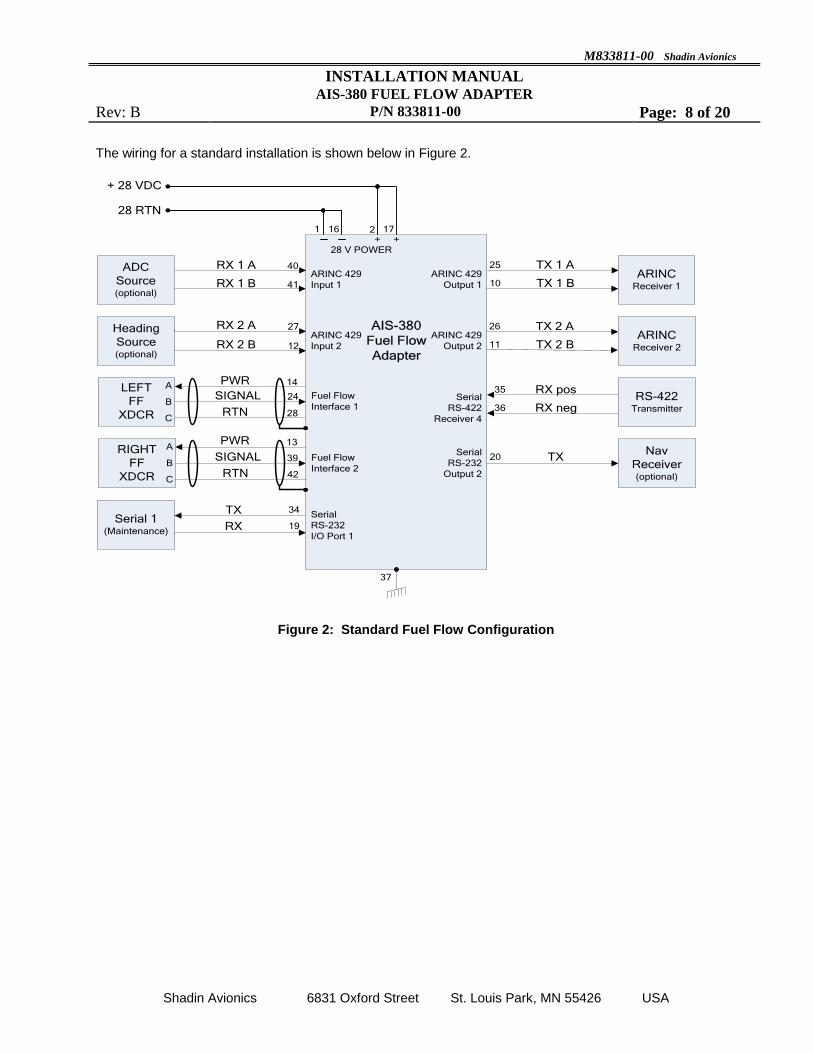
The wiring for a standard installation is shown below in Figure 2.
RX 1 A
RX 1 B
RX 2 A
RX 2 B
40
41
27
12
TX 1 A
TX 1 B
25
10
TX
RX
34
19
SIGNAL
SIGNAL
24
39
PWR
RTN
PWR
RTN
14
28
13
42
37
Fuel Flow
Interface 1
1721 16
+ 28 VDC
ARINC 429
Input 1
ADC
Source (optional)
Heading
Source (optional)
ARINC 429
Input 2
ARINC 429
Output 1
Fuel Flow
Interface 2
Serial
RS-232
I/O Port 1
Serial 1(Maintenance)
RX pos
RX neg
35
36
ARINC 429
Output 2
TX20Serial
RS-232
Output 2
Nav
Receiver(optional)
28 RTN
ARINCReceiver 2
+ +28 V POWER
Serial
RS-422
Receiver 4
TX 2 A
TX 2 B
26
11
AIS-380
Fuel Flow
Adapter
ARINCReceiver 1
RS-422Transmitter
LEFT
FF
XDCR
A
B
C
RIGHT
FF
XDCR
A
B
C
Figure 2: Standard Fuel Flow Configuration
M833811-00 Shadin Avionics
INSTALLATION MANUAL AIS-380 FUEL FLOW ADAPTER
Rev: B P/N 833811-00 Page: 9 of 20
Shadin Avionics 6831 Oxford Street St. Louis Park, MN 55426 USA
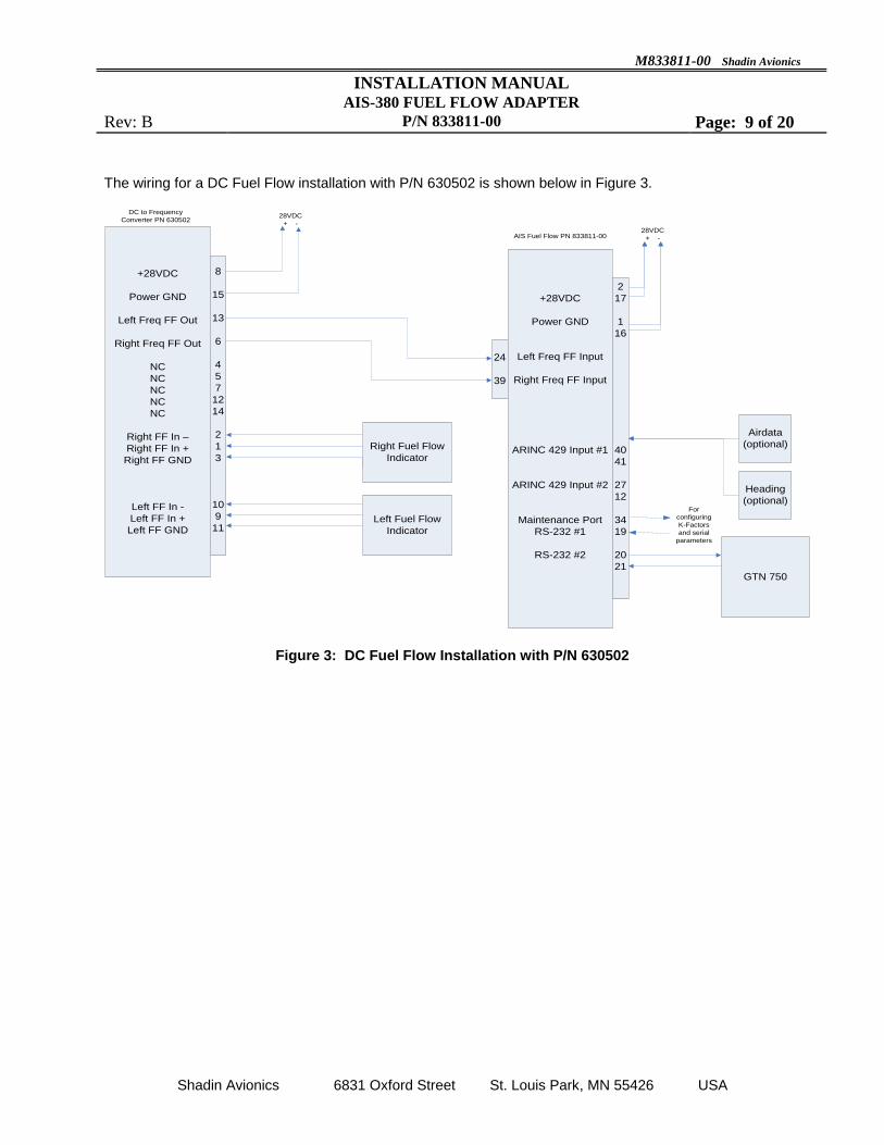
The wiring for a DC Fuel Flow installation with P/N 630502 is shown below in Figure 3.
+28VDC
Power GND
Left Freq FF Out
Right Freq FF Out
NC
NC
NC
NC
NC
Right FF In –
Right FF In +
Right FF GND
Left FF In -
Left FF In +
Left FF GNDLeft Fuel Flow
Indicator
8
15
13
6
4
5
7
12
14
2
1
3
10
9
11
Right Fuel Flow
Indicator
28VDC
+ -
24
39
DC to Frequency
Converter PN 630502
AIS Fuel Flow PN 833811-00
+28VDC
Power GND
Left Freq FF Input
Right Freq FF Input
ARINC 429 Input #1
ARINC 429 Input #2
Maintenance Port
RS-232 #1
RS-232 #2
2
17
1
16
40
41
27
12
34
19
20
21
28VDC
+ -
GTN 750
Airdata
(optional)
Heading
(optional)For
configuring
K-Factors
and serial
parameters
Figure 3: DC Fuel Flow Installation with P/N 630502

M833811-00 Shadin Avionics
INSTALLATION MANUAL AIS-380 FUEL FLOW ADAPTER
Rev: B P/N 833811-00 Page: 10 of 20
Shadin Avionics 6831 Oxford Street St. Louis Park, MN 55426 USA
The example for a Bell 412 EPI installation is shown below in Figure 4.
RX 1 A
RX 1 B
RX 2 A
RX 2 B
40
41
27
12
TX 1 A
TX 1 B
25
10
TX
RX
34
19
37
Fuel Flow
Interface 1
1721 16
+ 28 VDC
ARINC 429
Input 1
ADC
Source (optional)
Heading
Source (optional)
ARINC 429
Input 2
ARINC 429
Output 1
Fuel Flow
Interface 2
Serial
RS-232
I/O Port 1
Serial 1(Maintenance)
Bell ADIU
RX pos
RX neg
35
36
ARINC 429
Output 2
TX20Serial
RS-232
Output 2
Nav
Receiver(optional)
28 RTN
Flight
Display(optional)
+ +28 V POWER
Serial
RS-422
Receiver 4
TX 2 A
TX 2 B
26
11
AIS-380
Fuel Flow
Adapter
SIGNAL
SIGNAL
24
39
PWR
RTN
PWR
RTN
14
28
13
42
LEFT
FF
XDCR
A
B
C
RIGHT
FF
XDCR
A
B
C
Figure 4: Bell 412 EPI Installation
Provisional wiring and interconnections to the ADIU can be found in Bell STC SR09600RC.
1.7 INSTALLATION NOTES
Aircraft power +28 VDC can be connected to both pins 2 and 17 for redundancy as shown above. Alternatively the unit can be powered only through pin 2, or only through pin 17. The same applies to the return lines: Pins 1 and 16 can both routed to the aircraft 28 V return, or return can be connected to either pin 1 or pin 16. Pin 37 is tied directly to the AIS-380 chassis. After the AIS-380 is mounted to the airframe, this pin is equivalent to airframe ground and can be used as a connection to cable shields in the connector backshell. The Fuel Flow transducer wiring should be shielded twisted triple wires. Optimal shielding connections are shown above. Both fuel flow interfaces are wired identically. Tie each shield to pin 37 inside the backshell of the mating connector to the AIS-380. The shields are then left open at the transducer ends as shown.
M833811-00 Shadin Avionics
INSTALLATION MANUAL AIS-380 FUEL FLOW ADAPTER
Rev: B P/N 833811-00 Page: 11 of 20
Shadin Avionics 6831 Oxford Street St. Louis Park, MN 55426 USA
2 INSTALLATION
2.1 LIMITATIONS
The conditions and tests required for TSO approval of this article are minimum performance standards. It is the responsibility of those installing this article either on or within a specific type or class of aircraft to determine that the aircraft installation conditions are within the TSO standards. TSO articles must have separate approval for installation in an aircraft. The article may be installed only if performed under 14 CFR part 43 or the applicable airworthiness requirements.
This equipment is developed to Design Assurance Level (DAL C). TSO C44c lists the loss of fuel flow functionality to be Hazardous. It is the responsibility of those installing this article to determine if it meets the needs set forth in the System Safety Assessment.
2.1 INCOMPLETE SYSTEM
Shadin Avionics manufactures the AIS-380 833811 as an incomplete system under TSO-C44c, Fuel Flowmeters and performs to the relevant performance standards of AS407C, Fuel Flowmeters as tested by RTCA/DO-160F, Environmental Conditions and Test Procedures for Airborne Equipment.
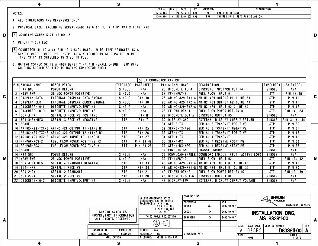
The AIS-380 is compatible with any fuel transducer whose output is a pulse/frequency in the range of 0 to +13VDC and within 2Hz to 2KHz. Installation Drawing D833811-00, included in Appendix A of this manual, provides connector J1 pin out information for proper wiring.
The AIS-380 provides data conversion for display. The installer must substantiate the interoperability when showing compliance to the applicable airworthiness.
2.1.1 PERFORMANCE STANDARDS
The AIS-380 meets the performance standards of AS407C paragraph 3.3 for Environmental Conditions, 4.5 for Power Variations, as defined in section 4 of this document in the Environmental Qualification Form (EQF) for an incomplete system to the fuel flowmeter. Scale errors are within 0.5% in accordance with paragraph 6.1 of AS407C.
2.2 MOUNTING
The AIS-380 FUEL FLOW ADAPTER (P/N 833811-00) can be mounted in any orientation in the aircraft. The hardware should be mounted using four (4) number 8 size screws in a dry location. The equipment should be installed in a controlled temperature and pressurized location.
2.3 ELECTRICAL CONNECTIONS
Installation Drawing D833811-00, included in Appendix A of this manual, provides connector J1 pinout information.
2.4 REPAIR
Units needing repair or that have failed should be returned to Shadin Avionics. Contact technical support for assistance by phone at (952) 927-6500 or (800) 388-2849, or email at [email protected]
M833811-00 Shadin Avionics
INSTALLATION MANUAL AIS-380 FUEL FLOW ADAPTER
Rev: B P/N 833811-00 Page: 12 of 20
Shadin Avionics 6831 Oxford Street St. Louis Park, MN 55426 USA
3 CONFIGURATION TOOL This section describes the use of the 833811 Fuel Flow Configuration Tool. The AIS-380 is to be configured on a test bench using the configuration tool prior to installation in the aircraft. Below is a list of the equipment needed and the instructions for installing and configuring the AIS-380 with the configuration tool.
Equipment List Installation Requirements for PC
+18 V to +28 V DC Power Supply Windows XP SP3 or Windows 7
CK833811 Configuration Kit for 833811* 1 MB hard disk space
Desktop or Laptop PC with serial port or USB adapter if no serial port is available
Intel® Pentium® Processor, 1.6 GHz minimum
500 MB RAM minimum
* Contact Shadin Tech Support to obtain CK833811:
Web: www.shadin.com E-mail: [email protected] Phone: (952) 927-6500 or
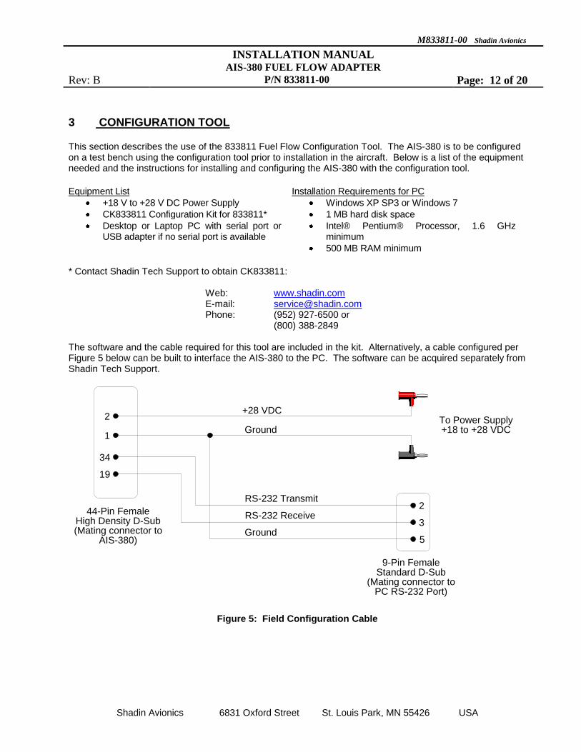
(800) 388-2849 The software and the cable required for this tool are included in the kit. Alternatively, a cable configured per Figure 5 below can be built to interface the AIS-380 to the PC. The software can be acquired separately from Shadin Tech Support.
+28 VDC
Ground
RS-232 Transmit
RS-232 Receive
2
1
34
19
2
5
3Ground
44-Pin FemaleHigh Density D-Sub(Mating connector to
AIS-380)
9-Pin Female Standard D-Sub
(Mating connector to PC RS-232 Port)
To Power Supply+18 to +28 VDC
Figure 5: Field Configuration Cable

M833811-00 Shadin Avionics
INSTALLATION MANUAL AIS-380 FUEL FLOW ADAPTER
Rev: B P/N 833811-00 Page: 13 of 20
Shadin Avionics 6831 Oxford Street St. Louis Park, MN 55426 USA
3.1 CONFIGURATION TOOL SOFTWARE INSTALLATION (1) Copy 463803.msi and setup.exe to a local folder on the PC. (2) Run setup.exe. The following dialog box will appear:
(3) Follow the Setup Wizard instructions. (4) After installation, confirm the following message is displayed: “AIS-380 Fuel Flow Configuration has been successfully installed.” (5) Close the AIS-380 Fuel Flow Configuration Wizard dialog box.

M833811-00 Shadin Avionics
INSTALLATION MANUAL AIS-380 FUEL FLOW ADAPTER
Rev: B P/N 833811-00 Page: 14 of 20
Shadin Avionics 6831 Oxford Street St. Louis Park, MN 55426 USA
3.2 USING THE CONGIRUATION TOOL (1) Connect the PC to the AIS-380 using the Field Configuration Cable. (2) Apply +28 VDC to the power leads of the Configuration cable which is connected to the AIS-380. (3) On the PC, navigate to the location of the 833811 Fuel Flow Configuration Tool icon which points to the newly installed program 463803.exe. Double-click the icon to start up the program. The following dialog box will appear:
(4) Select the appropriate COM Serial Port which is connected to the AIS-380 and press the Connect button.

M833811-00 Shadin Avionics
INSTALLATION MANUAL AIS-380 FUEL FLOW ADAPTER
Rev: B P/N 833811-00 Page: 15 of 20
Shadin Avionics 6831 Oxford Street St. Louis Park, MN 55426 USA
(5) Wait for the Software Version number to appear, and the status indicator located next to the software version number to turn from yellow to green. If the indicator remains yellow, check the serial port cable connections and re-run the program.
M833811-00 Shadin Avionics
INSTALLATION MANUAL AIS-380 FUEL FLOW ADAPTER
Rev: B P/N 833811-00 Page: 16 of 20
Shadin Avionics 6831 Oxford Street St. Louis Park, MN 55426 USA
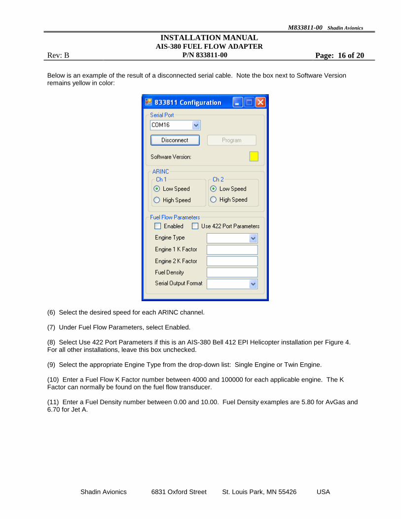
Below is an example of the result of a disconnected serial cable. Note the box next to Software Version remains yellow in color:
(6) Select the desired speed for each ARINC channel. (7) Under Fuel Flow Parameters, select Enabled. (8) Select Use 422 Port Parameters if this is an AIS-380 Bell 412 EPI Helicopter installation per Figure 4. For all other installations, leave this box unchecked. (9) Select the appropriate Engine Type from the drop-down list: Single Engine or Twin Engine. (10) Enter a Fuel Flow K Factor number between 4000 and 100000 for each applicable engine. The K Factor can normally be found on the fuel flow transducer. (11) Enter a Fuel Density number between 0.00 and 10.00. Fuel Density examples are 5.80 for AvGas and 6.70 for Jet A.

M833811-00 Shadin Avionics
INSTALLATION MANUAL AIS-380 FUEL FLOW ADAPTER
Rev: B P/N 833811-00 Page: 17 of 20
Shadin Avionics 6831 Oxford Street St. Louis Park, MN 55426 USA
(12) Select the applicable Serial Output Format based on the equipment that will be connected to SERIAL 2 in the planned aircraft installation. The serial output formats available are given in Table 2 below:
Table 2 – Serial Output Formats
SHADIN_Z
SHADIN_G
BENDIX_D_GPH
BENDIX_D_PPH
BENDIX_D_LPH
CHELTON
GENERIC_FF_GPH
GENERIC_FF_LPH
GENERIC_FF_PPH
(13) Press the Program button. Wait for the status indicator to turn from yellow to green. The AIS-380 configuration is now set.

M833811-00 Shadin Avionics
INSTALLATION MANUAL AIS-380 FUEL FLOW ADAPTER
Rev: B P/N 833811-00 Page: 18 of 20
Shadin Avionics 6831 Oxford Street St. Louis Park, MN 55426 USA
See the example below for a configuration with all fields completed:
(14) Turn power OFF to the AIS-380 and disconnect the configuration cable. The AIS-380 is now ready for aircraft installation.
M833811-00 Shadin Avionics
INSTALLATION MANUAL AIS-380 FUEL FLOW ADAPTER
Rev: B P/N 833811-00 Page: 19 of 20
Shadin Avionics 6831 Oxford Street St. Louis Park, MN 55426 USA
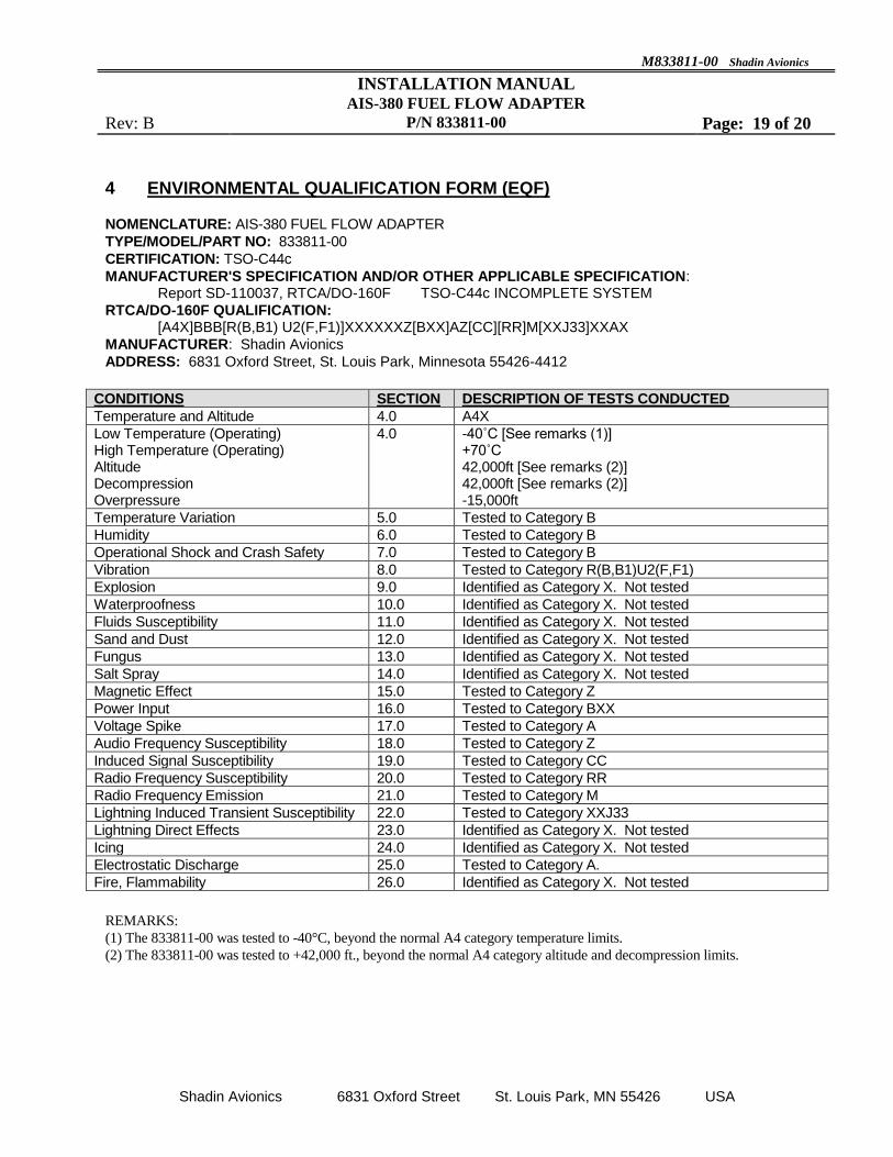
4 ENVIRONMENTAL QUALIFICATION FORM (EQF)
NOMENCLATURE: AIS-380 FUEL FLOW ADAPTER
TYPE/MODEL/PART NO: 833811-00
CERTIFICATION: TSO-C44c
MANUFACTURER'S SPECIFICATION AND/OR OTHER APPLICABLE SPECIFICATION: Report SD-110037, RTCA/DO-160F TSO-C44c INCOMPLETE SYSTEM
RTCA/DO-160F QUALIFICATION: [A4X]BBB[R(B,B1) U2(F,F1)]XXXXXXZ[BXX]AZ[CC][RR]M[XXJ33]XXAX
MANUFACTURER: Shadin Avionics
ADDRESS: 6831 Oxford Street, St. Louis Park, Minnesota 55426-4412
CONDITIONS SECTION DESCRIPTION OF TESTS CONDUCTED
Temperature and Altitude 4.0 A4X
Low Temperature (Operating) High Temperature (Operating) Altitude Decompression Overpressure
4.0 -40˚C [See remarks (1)] +70˚C 42,000ft [See remarks (2)] 42,000ft [See remarks (2)] -15,000ft
Temperature Variation 5.0 Tested to Category B
Humidity 6.0 Tested to Category B
Operational Shock and Crash Safety 7.0 Tested to Category B
Vibration 8.0 Tested to Category R(B,B1)U2(F,F1)
Explosion 9.0 Identified as Category X. Not tested
Waterproofness 10.0 Identified as Category X. Not tested
Fluids Susceptibility 11.0 Identified as Category X. Not tested
Sand and Dust 12.0 Identified as Category X. Not tested
Fungus 13.0 Identified as Category X. Not tested
Salt Spray 14.0 Identified as Category X. Not tested
Magnetic Effect 15.0 Tested to Category Z
Power Input 16.0 Tested to Category BXX
Voltage Spike 17.0 Tested to Category A
Audio Frequency Susceptibility 18.0 Tested to Category Z
Induced Signal Susceptibility 19.0 Tested to Category CC
Radio Frequency Susceptibility 20.0 Tested to Category RR
Radio Frequency Emission 21.0 Tested to Category M
Lightning Induced Transient Susceptibility 22.0 Tested to Category XXJ33
Lightning Direct Effects 23.0 Identified as Category X. Not tested
Icing 24.0 Identified as Category X. Not tested
Electrostatic Discharge 25.0 Tested to Category A.
Fire, Flammability 26.0 Identified as Category X. Not tested
REMARKS:
(1) The 833811-00 was tested to -40°C, beyond the normal A4 category temperature limits.
(2) The 833811-00 was tested to +42,000 ft., beyond the normal A4 category altitude and decompression limits.
M833811-00 Shadin Avionics
INSTALLATION MANUAL AIS-380 FUEL FLOW ADAPTER
Rev: B P/N 833811-00 Page: 20 of 20
Shadin Avionics 6831 Oxford Street St. Louis Park, MN 55426 USA
5 INSTALLATION DRAWINGS AND INSTALL KIT PARTS LIST
Appendix A: INSTALLATION DRAWING – D833811-00
Appendix B: INSTALL KIT, PARTS LIST – K833811-00


Shadin Avionics CAGE CODE: 0Z5P5
File Name: K833811-00-.DOC
ERN #: 1302/004
Rev: – Release Date: 2013/02/14
Approved: ZK
Page 1 of 1
PARTS LIST Part #: K833811-00
Drawing #s: NA Description: INSTALL KIT, AIS 833811-00
FN P/N QTY. DESCRIPTION MFG. MFG.# DESIGNATION COMMENTS
Shadin Avionics Proprietary Information - ALL RIGHTS RESERVED
5 232012 1 CONN, HD D-Sub 44 Pin, Female Crimp w/FC8022D2
Contacts
POS ODD44S1000X
10 232507 1 CONN, Backshell, 25P D-Sub, Zinc Die Cast APH 17E-1657-25
15 239004 1 TOOL, INSERT/EXTRACT M81969/1-04 NWK 59K0052
20 753217 1 Thermal Label, 4"x 1" ULI S-8601
25 PK1001 2 BAG, 2.5 x 3, 4 MIL Zip Lock
30 PK1007 1 BAG, 6 x 8, 4 MIL
7 items