Embed Size (px)
Citation preview

AIRWATER HIGH EFFICIENCY CHILLERS WITH EC FANS AND SCROLL
COMPRESSORS WITH INVERTER
Inverter Technology
Up to A Eurovent Class
Inverter Scroll Compressor
Axial fans
Microchannels coils
Outdoor installation
R410a Refrigerant
TECHNICAL BULLETIN EPIC Series RANGE Cooling capacity 48 ndash 232 kW
Cod BT ndash EPICndash E ndashMK ndash REV00 ndash0517 ndash UK
EPIC
1
1 Product description 2 Identification codes 3 Technical speciications 4 Accessories on demand regulation and certifications 5 Technical data 6 Operating range 7 Scaling correction schedules 8 Hydraulic data 9 Electrical data 10 Acoustic data 11 Dimensional drawings and weights
EPIC
2
1 PRODUCT DESCRIPTION
CONTINUOUS MODULATION OF THE COOLING CAPACITY ACCORDING TO THE PLANT THERMAL LOAD The compressors are characterized by continuous speed modulation The use of inverter allows the unit to partialize the total power down to 15
INVERTER COMPRESSORS The basic concept of the variable speed compressors is to allow their safe efficient and versatile operation in a frequency range from 30 to 80 Hz The new compact scroll compressors with inverter are characterized by a series of distinctive technical advantages
bull Reduced inverter dimensions
bull Reduction of the inrush currents in comparison to
traditional systems
bull Wider setting range
bull Precise capacity adjustment to installation loads
requirements
bull Electrical protection of the compressor integrated
into the inverter
MAXIMUM EFFICIENCY AT PARTIAL LOADS
A chiller usually works in nominal conditions for short periods during the whole year thus measuring the efficiency by EER is limiting Therefore in order to estimate the real energy consumption according to the different seasonal load conditions it is necessary to use the ESEER index EPIC units are properly designed and dimensioned with the aim to optimize the unit efficiency at partial loads Thanks to the full inverter control EPIC reaches ESEER values more than 30 higher compared to units equipped with constant speed scroll compressors
EPIC
3
EXTREMELY LOW NOISE IMPACT
Besides the high ESEER values EPIC is also characterized by extremely low noise impact When the unit works at partial loads thanks to the modulation of all components driven by electric motors such as fans and compressors the supplied cooling and heating capacity follows exactly the cooling and heating demand of the plant Consequently also the noise impact is significantly reduced under the partial load conditions For even more strict requirements in terms of noise impact there is a super low noise version characterized by several design features allowing to reduce even more the noise emission
SMOOTH AND PRECISE TEMPERATURE CONTROL
The technology used for variable speed compressor alows to guarantee a smooth and precise temperature control ensuring
bull Comfort level increased in shorter time
bull Reduced time to reach the setpoint
REDUCED INRUSH CURRENTS
The use of inverter compressors allow to reduce the inrush currents without using additional devices such as the delta star and avoiding the installation of expensive additional components for the power factor correction
EPIC
4
WFC TECHNOLOGY AND HIDRONIC KIT WITH INVERTER PUMPS (OPTIONAL)
The pumps are equipped with inverter-controlled motors suitable for frequency modulation and the same performance is obtained with 70 reduction of power input The WFC technology water flow control allows to adjust the rotation speed of the pumps through the inverter measuring out the correct amount of water flow according to the needs of the system by reducing the power input due to the pumping of the primary fluid
ELECTRONIC EXPANSION VALVE
The use of the electronic expansion valve allows to
Maximize the heat exchange at the evaporator Minimize the response time according to the load variation Optimize the superheating regulation and ensure the maximum energy
efficiency
MICROCHANNEL CONDENSING COILS
Air-cooled microchannel condensing coils with aluminum fins The coil is made up of three components the multichannel tubes the fins which are placed between the microchannels and the two refrigerant headers Main features - Reduced refrigerant charge thanks to new Microchannel technology (heat exchanger) the refrigerant charge is reduced by up to 37 compared to equivalent units with Al-Cu fin amp tube condensers - Compact The heat transfer surface in contact with the refrigerant is greatly increased so these heat exchangers are more compact and provide higher performance compared to the tube amp fin - Reduced emissions of refrigerant into the atmosphere lower emissions of refrigerant into the atmosphere with considerable benefits in terms of environmental protection - Reduced consumption and noise level with lower pressure drop in the air side and small size of microchannels condensing coils the turbulence on the condensing coil and pressure drops losses are reduced resulting in reduced noise power andor number of fans needed - Significant reductions in weight which is a double advantage a significant reduction of costs and maintenance time and at the same time lower CO2 emissions in transport Optional coatings are available to protect the coils and to increase the corrosion resistance and for the use in chemical risk environnement
EPIC
5
DYNAMIC LOGIC CONTROL
Thanks to the function DYNAMIC LOGIC CONTROL the electronic controller can manage the differential of the inlet water temperature on the basis of the speed of its variation The function dLC works partially as a simulator of a water tank in fact it allows to reduce the number of the compressorrsquos starts The main advantage of the function dLC is during the conditions of low load that is bull the compressor is switched off and the water temperature increases very slowly in this situation the dLC is able to delay the start of the compressor by replacing itself to the thermal inertia that would be obtained from the water tank bull the compressor is switched on and the water temperature decreases very quickly in this situation the dLC is able to delay the compressorrsquos switching off In this way it is reached the same result that would be obtained from the water tankrsquos thermal inertia As result the function dLC makes possible to reduce the dimensions of the water tank with huge advantages for the footprint of the unit Figure 1 shows how the compressorrsquos startups decrease by passing from a system with no tank and without dLC (1a) to a system with dLC (1b) and to a system with dLC and a small water tank (1c) It can be seen that this last solution is still the best though the tank dimensions can be reduced
EPIC
6
EC-BRUSHLESS ECOPROFILE FANS TECHNOLOGY
The new generation EC-BRUSHLESS ECOPROFILE fans ensure a higher efficiency thanks to lower energy consumption compared to traditional AC motors The EC motors allow therefore lower sound emissions during the air flow modulation The blade profile has been studied to reduce noise and ensure high acoustic comfort levels
ENERGY SAVING
The unit can be turned off according to time bands An innovative ENERGY SAVING function can be also activated to regulate the on-off of the unit By activating this function at certain time bands the controller will adjust the set point value to those required by the user Thanks to the Energy saving the unit will be ldquoforced to work morerdquo at certain time when the cost of electricity is lower or even to work less when there is a lower heating load The electronic control gives priority to the automatic shutdown if the two functions should be active for the same daily time band
DYNAMIC SET POINT
During the cooling season the outdoor temperature changes from the design temperature and consequently the cooling load of the plant changes too It is therefore possible to adjust the outlet water temperature according to outdoor temperature by the use of a set point regulation following a climatic curve
The function DYNAMIC SET POINT allows to change simultaneously the set point to achieve always theconditions of best comfort and above all the maximum energy saving In fact if the outdoor temperatureincreases through the function DSP it is possible bull To increase of a certain value the set point in case it is necessary to reduce the power consumption and it is needed to ensure a difference between the indoor and outdoor temperature such to avoid health problems due to the excessive changes of temperature bull To reduce of a certain value the set point in case it is required to compensate in such a way the excess of thermal load of course this is a function to be used with precaution because it generates higher power consumptions and a big difference in temperature between inside and outside that could be dangerous for the health of the people that is forced for any reason to get in and out from the air conditioned room
EPIC
7
2 IDENTIFICATION CODES The encoding of EPIC is simple and follows the rules defined by Thermocold for all other units
EPIC
2 150 Z C SL B1
Hydraulic version B1M1A1 One pump and expansion vessel B2M2A2 Two pumps ad expansion vessel
Acoustic version SL Super low noise
Basic version C Chiller
Type of compressor Z Scroll compressor R410a
Nominal cooling capacity (kW)
Number of circuits
Example of typical identification code EPIC 150 ZC SL B1
EPIC
8
3 TECHNICAL SPECIFICATIONS The units belonging to EPIC range are air-water chillers for outdoor installation equipped with inverter scroll compressors and EC axial fans available in 9 sizes and in the following basic version
C Chiller
EPIC units are available in a wide setting up ranges in order to guarantee a high satisfaction level for different plant applications
ACOUSTIC VERIONS (to be associated with the basic version) SL super low noise units The noise reduction is achieved by reduced fans speed in accordance with the condensing pressure muffler on the compressors delivery lines soundproof insulation box for compressors and Axitop diffuser Compared to basic versions SL versions allows a reduction of about 5 dB(A) in sound levels HYDRAULIC VERSIONS (Integrated hydraulic kit available for On-Off pumps andor Inverter pumps) ONE PUMP AND EXPANSION VESSEL B1 Low available pressure 150kPa M1 Medium available pressure 250kPa A1 High available pressure 450kPa TWO PUMPS AD EXPANSION VESSEL B2 Low available pressure 150kPa M2 Medium available pressure 250kPa A2 High available pressure 450kPa CASING Casing made with heavy gauge structure in galvanized steel The powder paint anti-corrosive treatment over the entire frame provides long lasting resistance for outdoor installation even in aggressive environmental conditions Its design allows these machines to be manufactured in modular units and at same time it ensures a constant air flow through the finned coils and makes for easy maintenance and service COMPRESSORS The units are equipped with hermetic scroll compressors with Inverter technology characterized by high performances reduced vibrations and little sound emissions During operation itrsquos developed a more uniform compression and pulsation there are no alternative movements of pistons accompanied by masses or vibration forces to benefit the low noise High performance values are guaranteed by high volumetric efficiency During operation The compressor maintains a supply of power output with limited variations it guaranteed continuous operation of the compressor with limited number of stat and stops than the other type of compressors The inverter technology applied to last generation compressors allows to control and to adapt the speed of the compressor in relation to the set-point Reached the required temperature it is kept constant modulating the power delivered to a minimum ensuring much higher energy saving For this reason it is possible to save energy faster in achieving the desired set-point The temperature of the gas flow is significantly lower thanks to the limited internal heat of the gas aspirated it allows you to work with pressures condensation reduced with more comfort and much long life cycle of the compressor The electric inverter motor cooled by the refrigerant inlet it is equipped with internal thermal protection FANS The technology of ECO-PROFILE ELECTRONIC propeller fans has blades statically and dynamically balanced driven directly by the DC Brushless electric motors closed type external rotor and thermal protection for outdoor installation protected to IP 54 ECO-PROFILE fans are characterized by low speed and ldquoowletrdquo profile to reduce the effect of vortices thereby reducing the energy consumed for operation and noise reducing it by an average of 6dB (A) compared with standard fans The EC fans are also equipped with an integrated control for the continuous modulation of the fans speed according to the condensing pressure allowing minimum power input and ensuring the maximum efficiency of the circuit PLATE HEAT EXCHANGER Direct expansion stainless steel AISI 316 brazed plate type with double circuit externally insulated with closed cell anticondensation material and equipped with water differential pressure switch and antifreeze protection electric heater
EPIC
9
SOURCE HEAT EXCHANGER MICROCHANNELS COILS Air-cooled microchannel condensing coils with aluminum fins The coil is made up of three components the multichannel tubes the fins which are placed between the microchannels and the two refrigerant headers Main features - Reduced consumption and noise level with lower pressure drop in the air side and small size of microchannels condensing coils the turbulence on the condensing coil and pressure drops losses are reduced resulting in reduced noise power andor number of fans needed - Compact the heat transfer surface in contact with the refrigerant is greatly increased so these heat exchangers are more compact and provide higher performance compared to the tube amp fin - Reduced refrigerant charge thanks to new Microchannel technology (heat exchanger) the refrigerant charge is reduced by up to 37 compared to equivalent units with Al-Cu fin amp tube condensers - Reduced emissions of refrigerant into the atmosphere with considerable benefits in terms of environmental protection - Significant reductions in weight which is a double advantage a significant reduction of costs and maintenance time and at the same time lower CO2 emissions in transport Optional coatings are available to protect the coils and to increase the corrosion resistance and for the use in chemical risk environnement REFRIGERANT CIRCUIT The units are equipped with two independent refrigerant circuits entirely constructed with copper tubes each supplied by its own compressor Each circuit includes
bull Refrigerant charge R410a
bull Electronic expansion valve
bull Filter drier with interchangeable cartridge suitable for the use of ecological fluids and polyesters oils
bull Indicator lamp for liquid flow and humidity presence
bull Shut off valve on the liquid line complete of balancing pressure system making easier the opening and closing operations
bull Solenoid valve on the liquid line
bull High pressure switch
bull Low pressure switch
bull Safety valve on the discharge line
bull Safety valve on the suction line
bull High pressure transducers
bull Low pressure transducers ELECTRICAL PANEL The electrical panel made in accordance with CEI-EN 60204-1 (CEI44-5 CEI EN 62061) standards is housed in watertight box the opening system of the box needs the use of a retractable handle or dedicated tools in each case the opening is allowed only after disconnection of the power supply through the main switch with door lock handle lockable in OFF position The electrical panel includes bull Protection fuses for the supply line of each compressor bull Protection fuses for the supply line of fans for each refrigerant circuit bull Protection fuses of auxiliary circuit bull Start up contactors for compressors OnOff (size with tandem Inverter+OnOff) dimensioned according to the maximum stress bull VSD for compressor bull Start up contactors for fans bull Adjustable thermal magnetic circuit breaker for the protection of the pump (only in case of units equipped with hydraulic kit) bull Start up contactors for pump (only in case of units equipped with hydraulic kit) bull single-phase transformer for the power supply of the auxiliary circuits bull numbered wires bull microprocessor control In case of phase failure an automatic system protects fans and compressors The wiring of the electric panel and the connection with the components of the units are made using cables appropriately calculated for operation at 55degC and according to the maximum electrical stress of the components All the cables and the terminals are univocally numbered according to the electrical scheme in order to avoid possible misinterpretation The identification system of the cables connected to the components allow also an easy and intuitive recognition of the component
EPIC
10
Each component of the electrical panel is provided with an identification plate according to what is shown on the electrical scheme All the connection to the electrical panel are made from the bottom and are equipped with cover preventing from break The electrical panel supply is 400V3ph+n50Hz and no additional power supply is necessary The input of the power cables is provided on the bottom of the box where it is provided a dismountable flange suitable for the purpose
POWER AND CONTROL ELECTRICAL PANEL
The units are controlled by one single device that handles all circuits The keypad allows a complete and intuitive display of all the main control variables of both circuits The programmable controller is based on a powerful platform with 256bit microprocessor 4MB mass storage with a hardware and software configuration made with the most innovative technology in terms of processing speed and connectivity The diagnostics includes a complete alarm management alarm history and data logger which stores an archive of about 4 days (further expandable by USB memory) where the main variables and the operating status of the unit are recorded ModBus master and slave communication protocol The temperature regulation us carried out by two hydraulic circuits (cooled water and hot water) with a continuous proportional logic according to the return water temperature The operating parameters of the machine are protected by 3 levels of password (user-maintainer-builder) The user panel provides information LCD dysplay with exhaustive descriptions in Italian and English (selectable)
Ability to interface with the main BMS systems via RS485 BacNet and Lontalk Ability to interface with IO expansion modules via CanBus Ability to control the unit by voltage free contacts Input Ethernet RJ45 for routing on the web of all the parameters of the unit providing a total remote control of
unit USB input to upload parameter files system files firmware and to download files of historical alarms residing
parameters files and default parameters files User interface on the door of the panel low-reflection LCD equipped with 8 function keys easy iconic display
easy sliding between the dynamic screens Control of condensation air through an inverter directly managed by the electronic controller based on
proportional logic Management of electronic expansion valves through controller based on PID logic with LOP control (low
operating pressure) maintenance of the minimum working pressure and of the MOP (maximum operating pressure) for the management of the maximum working pressure
Management of the inverter pump of the cold user side with a continuous proportional signal managed by the electronic
The microprocessor manages Starting of the compressors with the start-up and stop time control Fans start up and modulation according with condensation pressure Solenoid valves of liquid lines with pump-down management during stops through double control of sunction
pressure and maximum time of the procedure Electric anti-freeze heater for user exanchangers Water pumps management through voltage free contacts for standard versions for hydraulic versions the pump
management is automatically controlled General alarm signal for the unit through voltage free contacts
The microprocessor will control and display by suitable measuring transducers the following variables Inlet and outlet water temperature to the user exchanger Outdoor temperature Condensing pressure of each refrigerant circuit Evaporating pressure of each refrigerant circuit Total operating time of each compressor
EPIC
11
Total operating time of the unit The microprocessor will protect the unit in the following cases the resetting of any alarm will always be manual
Low evaporating pressure by analogical and digital input with possibility to edit the marking details High condensing pressure by analogical and digital input High temperature of the compressors windings Reverse rotation of each compressor Low pressure difference between discharge and suction (to allow a correct lubrification of the compressor) with
the possibility to edit the start-up delay and the minimum requested value High pressure difference on the oil filter High temperature of fans motor windings High temperature of pumps motor windings Lack of water flow on evaporator Low evaporator outlet water temperature
It is also possible to display and edit through the microprocessor the following value Operating setpoint of the unit Operating differential of the unit Set point and anti-freeze block differential Set point and differential of activation of the evaporator heater Minimum operating time of each compressor Minimum stop time of each compressor Maximum number of starts per hour of each compressor Set point and optimal condensation pressure differential (condensation control)
Other functionalities ensured from the microprocessor are Activating of preventive functions at extreme conditions of high pressure Activating of preventive functions at extreme conditions of low pressure Activation of preventive functions at limit conditions of high discharge temperature Activating preventive functions at extreme conditions of low evaporator leaving water temperature Activating preventive functions at extreme conditions of high evaporator inlet water temperature Protection from unwanted changes of the parameters thanks of the use of password and systems to confirm the
changed data Indication of the unit status and the components status Possibility to exclude each compressor for the maintenance Possibility to change the set point by external analog signal Possibility of ONOFF remote signal through digital external signal Communication with supervision systems (data and parameters exchange) Continuous adjustment of the set point according to the outdoor air temperature both with direct and reverse
direction logic (DSP) Auto power on-off of the unit using time slots Adjustment of the set point by time bands both with direct and reverse direction logic (Energy Saving)
EPIC
12
4 ACCESSORIES ON DEMAND REGULATION AND CERTIFICATIONS
MOUNTED ACCESSORIES
bull Power factor correction to cos phi 091
bull Control panel electric heater with thermostat
bull Water pumps automatic changeover
bull Phase failure protection relay
bull Serial card with BacNet Protocol MSTP
bull Serial card with BacNet Protocol TCPIP
bull Gateway Modbus Lontalk
bull Soft - Start (only for ON-OFF compressors)
bull Power supply without neutral
bull Automatic circuit breakers(only for ON-OFF compressors)
bull High Static Pressure ECO-PROFILE ELECTRONIC Fans 100 Pa
bull Gas gauges
bull Low outdoor temperature kit up to -10degC (in cooling mode only)
bull Complete anti-intrusion grilles
bull Compressor jackets sound attenuators
bull Powder coated condensing coils
bull Anti-corrosion coated condensing coil
LOOSE ACCESSORIES
bull Remote control display
bull Sea container kit
bull Flow switch
bull Automatic water filling
bull Water strainer
bull Water gauges
bull Victaulic Kit
bull Victaulic adapter
bull Rubber anti vibration mounts
bull Spring antivibration mounts
EPIC
13
CERTIFICATIONS PED RELEASED FROM IMQ SPA - NOTIFIED BODY FOR REGULATION 201468UE (NO 0051) ACCORDING TO
THE FOLLOWING STATEMENTS - DECLARATION OF QUALITY SYSTEM APPROVAL - FORM H1 (QUALITY ASSURANCE WITH DESIGN
CONTROL AND MONITORING OF FINAL CHECK DETAIL) CERTIFICATE N PEC-0051-1105003 - CERTIFICATES OF EXAMINATION OF THE PROJECT N 0051-PEC-110500405060708
ACCORDING TO THE STANDARD QUALITY CERTIFICATION UNI EN ISO 90012008 ISSUED BY CSQ (ACCREDITED
ACCREDIA) CERTIFICATION OF PERFORMANCE UNIT BY MEANS OF TESTING TO PRESENT WHEN THE THIRD BODY - RINA
SPA (OPTIONAL) GOST - (OPTIONAL) FOR PRESSURE RECIPIENTS OF THE RUSSIAN FEDERATION
REFERENCE STANDARD THE PRESSURE EQUIPMENT DIRECTIVE 201468UE UNI EN ISO 3744 ACOUSTIC REGULATION UNI-EN-ISO 90012008 QUALITY MANAGEMENT SYSTEMS LOW VOLTAGE DIRECTIVE (LVD) 201435UE MACHINERY DIRECTIVE 200642EC DIRECTIVE FOR ELECTROMAGNETIC COMPATIBILITY 201430EU CEI-EN 60204-1 DIRECTIVE (CEI44-5 CEI EN 62061) MACHINERY SAFETY ndash ELECTRIC MACHINERY ndash EQUIPMENTS ERP DIRECTIVE (ENERGY-RELATED-PRODUCTS ECODESIGN 2009125CE) UNI EN 14511-1-2-3-4 TESTING CONDITIONS
EPIC
14
5 TECHNICAL DATA GENERAL TECHNICAL DATA EPIC
MODELLO 150 ZC 170 ZC 180 ZC 1115 ZC
Cooling (1)
Total cooling capacity kW 484 6778 809 114
Compressors power input kW 130 200 221 310
Total EER 302 295 304 308
ESEER 441 447 451 449
EER CLASS B B B B
Water flow msup3h 83 117 139 196
Water pressure drop kPa 305 264 359 237
COMPRESSORS
Compressors number n 1 1 2 2
Refrigerant circuits n 1 1 1 1
Part load n INVERTER REGULATION 15-100
Refrigerant charge kg 80 84 123 165
Oil charge dm^3 36 67 69 134
FANS
Fans number n 2 2 3 4
Air flow msup3h 35200 35200 52800 70400
Power input for each fan kW 15 15 15 15
Absorbed current for each fan A 3 3 3 3
SOUND LEVEL
Sound power level (ISO 3744) dB(A) 87 92 88 93
Sound pressure level at 10 m (ISO 3744) dB(A) 55 60 56 61
DIMENSIONS AND WEIGHT
Length mm 2461 2461 3599 2257
Deepth mm 1100 1100 1100 2146
Height mm 2179 2179 2179 2175
Operanting Weight kg 598 657 954 1226
Shipping Weight kg 593 652 946 1218
(1) Outdoor air temperature 35 degC ndash Outlet water temperature 127 degC
EPIC
15
GENERAL TECHNICAL DATA
EPIC
MODELLO 2135 ZC 2150 ZC 2185 ZC 2215 ZC 2230 ZC
Cooling (1)
Total cooling capacity kW 134 151 183 214 232
Compressors power input kW 393 414 479 599 664
Total EER 297 299 305 298 296
ESEER 427 427 418 411 424
EER CLASS B B B B B
Water flow msup3h 231 260 315 368 399
Water pressure drop kPa 290 342 295 424 383
COMPRESSORS
Compressors number n 2 4 4 4 4
Refrigerant circuits n 2 2 2 2 2
Part load n INVERTER REGULATION 15-100
Refrigerant charge kg 166 239 321 321 325
Oil charge dm^3 134 138 144 206 268
FANS
Fans number n 4 6 8 8 8
Air flow msup3h 70400 105600 140800 140800 140800
Power input for each fan kW 15 15 15 15 15
Absorbed current for each fan A 3 3 3 3 3
SOUND LEVEL
Sound power level (ISO 3744) dB(A) 95 91 92 94 96
Sound pressure level at 10 m (ISO 3744) dB(A) 63 59 60 62 64
DIMENSIONS AND WEIGHT
Length mm 2257 3421 4550 4550 4550
Deepth mm 2146 2138 2244 2244 2244
Height mm 2175 2469 2458 2458 2458
Operanting Weight kg 1283 1897 2297 2421 2543
Shipping Weight kg 1270 1884 2280 2404 2522
(1) Outdoor air temperature 35 degC ndash Outlet water temperature 127 degC
EPIC
16
GENERAL TECHNICAL DATA
EPIC SL
MODELLO 150 ZC 170 ZC 180 ZC 1115 ZC
Cooling (1)
Total cooling capacity kW 477 650 793 110
Compressors power input kW 139 210 235 328
Total EER 317 293 316 314
ESEER 458 463 471 479
EER CLASS A B A A
Water flow msup3h 82 112 136 189
Water pressure drop kPa 296 243 345 221
COMPRESSORS
Compressors number n 1 1 2 2
Refrigerant circuits n 1 1 1 1
Part load n INVERTER REGULATION 15-100
Refrigerant charge kg 80 84 123 165
Oil charge dm^3 36 67 69 134
FANS
Fans number n 2 2 3 4
Air flow msup3h 24640 24640 36960 49280
Power input for each fan kW 055 055 055 055
Absorbed current for each fan A 11 11 11 11
SOUND LEVEL
Sound power level (ISO 3744) dB(A) 82 87 83 88
Sound pressure level at 10 m (ISO 3744) dB(A) 50 55 51 56
DIMENSIONS AND WEIGHT
Length mm 2461 2461 3599 2257
Deepth mm 1100 1100 1100 2146
Height mm 2179 2179 2179 2175
Operanting Weight kg 782 841 1192 1518
Shipping Weight kg 777 836 1181 1510
(1) Outdoor air temperature 35 degC ndash Outlet water temperature 127 degC
EPIC
17
GENERAL TECHNICAL DATA
EPIC SL
MODELLO 2135 ZC 2150 ZC 2185 ZC 2215 ZC 2230 ZC
Cooling (1)
Total cooling capacity kW 130 144 181 210 222
Compressors power input kW 413 453 514 639 709
Total EER 299 297 324 307 295
ESEER 417 419 425 429 415
EER CLASS B B A B B
Water flow msup3h 223 249 311 361 382
Water pressure drop kPa 270 314 289 408 351
COMPRESSORS
Compressors number n 2 4 4 4 4
Refrigerant circuits n 2 2 2 2 2
Part load n INVERTER REGULATION 15-100
Refrigerant charge kg 166 239 321 321 325
Oil charge dm^3 134 138 144 206 268
FANS
Fans number n 4 6 8 8 8
Air flow msup3h 49280 73920 98560 98560 98560
Power input for each fan kW 055 055 055 055 055
Absorbed current for each fan A 11 11 11 11 11
SOUND LEVEL
Sound power level (ISO 3744) dB(A) 90 86 86 89 91
Sound pressure level at 10 m (ISO 3744) dB(A) 58 53 54 57 59
DIMENSIONS AND WEIGHT
Length mm 2257 3421 4550 4550 4550
Deepth mm 2146 2138 2244 2244 2244
Height mm 2175 2469 2458 2458 2458
Operanting Weight kg 1651 2373 2881 3005 3127
Shipping Weight kg 1638 2360 2864 2988 3106
(1) Outdoor air temperature 35 degC ndash Outlet water temperature 127 degC
EPIC
18
6 OPERATING RANGE
Version Operating way Ta Tw out
Min Max Min Max
C Cooling -10(2) 47 -6 (1) 18
(1) Operation with glycol (2) Only with Low Outodoor Temperature kit (optional) Ta = Outdoor air temperature (degC)
Tw out = Outlet water temperature (degC)
EPIC
19
7 SCALING CORRECTION SCHEDULES
FOULING FACTOR CORRECTION TABLE
Fouling Factor Plant side cold heat exchanger
FF A1 B1 Tmin
[m^2degCW]
0 100 100 000
180E-05 100 100 000
440E-05 100 100 000
880E-05 096 099 070
132E-04 094 099 100
172E-04 093 098 150
A factor Capacity correction factor B factor Compressor power input correction factor Tmin Minimum evaporator outlet water temperature increase
T max Maximum condenser outlet water temperature descrease
EPIC
20
8 HYDRAULIC DATA WATER FLOW AND RECOMMENDED WATER CONTENT OF THE PLANT
EPIC
Plant side Cold Heat Exchanger
COOLING Vminimo Vottimale K Q min Q max
P Q dpw [m3] [m3]
[m3h] [m3h]
150 ZC 484 832 305 02 03 440 52 139
170 ZC 678 1166 264 03 04 1942 73 194
180 ZC 809 1391 359 04 05 1854 87 232
1115 ZC 114 1957 237 05 07 619 122 326
2135 ZC 134 2312 29 06 09 542 145 385
2150 ZC 151 2597 342 07 1 508 162 433
2185 ZC 183 3146 295 08 12 298 197 524
2215 ZC 214 3683 424 1 14 313 23 614
2230 ZC 232 3993 383 11 15 24 25 666
150 ZC SL 477 82 296 02 03 4398 51 137
170 ZC SL 65 1118 243 03 04 1942 7 186
180 ZC SL 793 1364 345 04 05 1854 85 227
1115 ZC SL 110 1889 221 05 07 619 118 315
2135 ZC SL 130 2232 27 06 08 542 14 372
2150 ZC SL 144 2485 314 07 09 508 155 414
2185 ZC SL 181 3113 289 08 12 298 195 519
2215 ZC SL 210 3612 408 1 13 313 226 602
2230 ZC SL 222 3824 351 1 14 24 239 637
V recommended water content of the plant (cold side and hot side) with dT 5 deg C on the heat exchanger
Q min minimum water flow admitted to the excharger
Q max maximum water flow admitted to the excharger
dPw = KQ2 1000
P Heating capacity [kW]
Δt ΔT at heat exchange (min =3 max = 8) [degC]
Dpw Pressure drop [kPa]
EPIC
21
HYDRAULIC VERSIONS The units of the EPIC family are also available in multiple hydraulic versions characterized by complete kits of all major hydraulic components for an easier installation with reduced time cost and space The wide range of hydraulic versions available make the unit suitable for any type of installation HYDRAULIC VERSIONS (Integrated hydraulic kit available for On-Off pumps andor Inverter pumps) B1M1A1 One pump and expansion vessel B2M2A2 Two pumps ad expansion vessel
Centrifugal pumps with 2 poles axial suction bowls and radial delivery available in low medium or high head pressure Pumps with cast iron body and impeller entirely welded usinjg laser technology Mechanical seal with ceramic components coal and EPDM elastomers Three phase electric motor with IP55 protection and insulation class F suitable for continuous service Series motors with higher efficiency IE3 technology bull Differential pressure switch on exchanger bull Service valve bull Taps on pumps suction delivery which allow the replacement of a damaged pump eliminating the plant shutdown differently from other types of common use bull Check valve bull Relief valve bull Discharge valve The water pumps automatic changeover for hydraulic versions equipped with two pumps is also available as optional The pumps operate with the balance of the related working hours In case of failure of one pump the controller in automatic switches on the additional pump The control panel is equipped with fuses and contactor with thermal protection HYDRONIC ACCESORIES ON REQUEST bull Water pumps automatic changeover for 2 pumps hydraulic kits which also includes the secondary pump pressure switch bull ldquoYrdquo water strainer (sold separately) consists of body and stainless steel mesh with replaceable filter through the inspection cap bull Automatic water filling (sold separately)
EPIC
22
LOW HEAD PRESSURE PUMP (150 kPa)
COOLING ONLY MODE
Model Pf qw dpw Rif Curve Expansion vessel
On-off Pumps Hp Hu
FLI FLA
[kW] [m^3h] [kPa]
[l] [kW] [A] [kPa] [kPa]
150 484 83 305 A 5 177 330 212 181
170 68 117 264 A 5 177 330 193 166
180 81 139 359 B 5 178 380 190 154
1115 114 196 237 C 5 255 470 209 185
2135 134 231 290 C 12 255 470 209 180
2150 151 260 342 D 12 344 640 214 180
2185 183 315 295 D 12 344 640 194 164
2215 214 368 424 E 12 452 870 244 201
2230 232 399 383 E 12 452 870 239 200
Pf Cooling capacity (kW) qw Water flow (m3h) dpw Pressure drop (kPa) FLI Full load electrical power input FLA Full load operating current Hp Pump Head pressure Hu Available head pressure
EPIC
23
MEDIUM HEAD PRESSURE PUMP (250 kPa)
COOLING ONLY MODE
Model Pf qw dpw Rif Curve Expansion vessel
On-off Pumps Hp Hu
FLI FLA
[kW] [m^3h] [kPa]
[l] [kW] [A] [kPa] [kPa]
150 484 83 305 F 5 255 470 333 303
170 68 117 264 F 5 255 470 313 287
180 81 139 359 F 5 255 470 297 261
1115 114 196 237 G 5 452 870 349 325
2135 134 231 290 G 12 452 870 337 308
2150 151 260 342 G 12 452 870 326 292
2185 183 315 295 H 12 610 1060 313 284
2215 214 368 424 H 12 610 1060 304 261
2230 232 399 383 H 12 610 1060 297 259
Pf Cooling capacity (kW) qw Water flow (m3h) dpw Pressure drop (kPa) FLI Full load electrical power input FLA Full load operating current Hp Pump Head pressure Hu Available head pressure
EPIC
24
HIGH HEAD PRESSURE PUMP (450 kPa)
COOLING ONLY MODE
Model Pf qw dpw Rif Curve Expansion vessel
On-off Pumps Hp Hu
FLI FLA
[kW] [m^3h] [kPa]
[l] [kW] [A] [kPa] [kPa]
150 484 83 305 I 5 425 87 494 463
170 68 117 264 I 5 425 87 473 446
180 81 139 359 I 5 425 87 455 419
1115 114 196 237 L 5 826 136 543 519
2135 134 231 290 L 12 826 136 528 499
2150 151 260 342 L 12 826 136 514 480
2185 183 315 295 L 12 826 136 533 503
2215 214 368 424 M 12 1198 213 520 478
2230 232 399 383 M 12 1198 213 512 474
Pf Cooling capacity (kW) qw Water flow (m3h) dpw Pressure drop (kPa) FLI Full load electrical power input FLA Full load operating current Hp Pump Head pressure Hu Available head pressure
EPIC
25
CONNECTION SCHEME - STANDARD VERSION
Note a water strainer shall always be installed on the inlet water pipe
EPIC
26
HYDRONIC KIT WITH 1 PUMP ndash B1M1A1
Note a water strainer shall always be installed on the inlet water pipe
EPIC
27
HYDRONIC KIT WITH 2 PUMPS - B2M2A2
Note a water strainer shall always be installed on the inlet water pipe
EPIC
28
9 ELECTRICAL DATA
EPIC
NOMINAL VALUES MAXIMUM VALUES (1)
Outdoor air temperature 35degC evaporator water temperature inout 127degC
Model
Compressors (2) Fans TOTAL TOTAL
FLI FLA LRA EP OC FLI FLA SA FLI FLA SA
kW A A kW A kW A A kW A A
150 ZC 130 222 550 30 60 160 282 610 230 410 610
170 ZC 200 298 763 30 60 230 358 823 313 556 823
180 ZC 221 395 1470 45 90 266 485 1730 375 667 1787
1115 ZC 310 516 1700 60 120 370 636 2053 509 905 2109
2135 ZC 393 596 763 60 120 453 716 1181 627 1112 1379
2150 ZC 414 792 1470 90 180 504 972 2216 749 1334 2454
2185 ZC 479 865 1970 120 240 599 1105 2854 855 1526 3146
2215 ZC 599 1009 2150 120 240 719 1249 3113 987 1757 3529
2230 ZC 664 1148 2600 120 240 784 1388 3653 1118 1987 4121
EPIC SL
NOMINAL VALUES
MAXIMUM VALUES (1) Outdoor air temperature 35degC evaporator water temperature inout 127degC
Model
Compressors (2) Fans TOTAL TOTAL
FLI FLA LRA EP OC FLI FLA SA FLI FLA SA
kW A A kW A kW A A kW A A
150 ZC 139 224 550 11 22 150 246 572 230 410 610
170 ZC 210 301 763 11 22 221 323 785 313 556 823
180 ZC 234 398 1470 17 33 251 431 1674 375 667 1787
1115 ZC 328 520 1700 22 44 350 564 1978 509 905 2109
2135 ZC 413 601 763 22 44 435 645 1108 627 1112 1379
2150 ZC 453 797 1470 33 66 486 863 2106 749 1334 2454
2185 ZC 514 871 1970 44 88 558 959 2706 855 1526 3146
2215 ZC 639 1017 2150 44 88 683 1105 2967 987 1757 3529
2230 ZC 709 1157 2600 44 88 753 1245 3508 1118 1987 4121
Electrical data referred to 400V - 3PH+N-50Hz Maximum operating admitted conditions 10 Maximum phase unbalance 3 FLI full load electrical power with max thermal load FLA full load operating current with max thermal load LRA compressor motor locked rotor current (direct starting) SA sum of LRA of the most powerful compressor FLA of other compressor and fans current EP electrical power OC operating current
(1) Values to be considered in the sizing of the power cables and line protection (2) Data referred to the biggest compressor for units with different compressors
EPIC
29
10 ACOUSTIC DATA EPIC
Model
Octave Band (Hz) Lw (db(A)
63 125 250 500 1000 2000 4000 8000
Sound power level (dB)
150 Z 645 605 559 517 493 645 470 360 87
170 Z 695 655 609 567 543 695 520 410 92
180 Z 653 613 567 525 501 653 478 368 88
1115 Z 704 664 618 576 552 704 529 419 93
2135 Z 724 684 638 596 572 724 549 439 95
2150 Z 682 642 596 554 530 682 507 397 91
2185 Z 690 650 604 562 538 690 515 405 92
2215 Z 710 670 624 582 558 710 535 425 94
2230 Z 730 690 644 602 578 730 555 445 96 NOTE The data reported in the table refer to units without the hydraulic version
EPIC SL
Model
Octave Band (Hz) Lw (db(A)
63 125 250 500 1000 2000 4000 8000
Sound power level (dB)
150 Z 595 555 509 467 443 595 420 310 82
170 Z 645 605 559 517 493 645 470 360 87
180 Z 603 563 517 475 451 603 428 318 83
1115 Z 654 614 568 526 502 654 479 369 88
2135 Z 674 634 588 546 522 674 499 389 90
2150 Z 632 592 546 504 480 632 457 347 86
2185 Z 640 600 554 512 488 640 465 355 87
2215 Z 660 620 574 532 508 660 485 375 89
2230 Z 680 640 594 552 528 680 505 395 91 NOTE The data reported in the table refer to units without the hydraulic version
EPIC
30
NOISE CORRECTION FACTORS FOR HYDRAULIC VERSION
For the Hydraulic version please consider the noise output increase due to the addition of the hydraulic group EPIC
Modelli
bassa prevalenza media prevalenza alta prevalenza
1 pompa 2 pompe 1 pompa 2 pompe 1 pompa 2 pompe
[dB(A)] [dB(A)] [dB(A)] [dB(A)] [dB(A)] [dB(A)]
150 ZC 03 03 04 04 08 08
170 ZC 01 01 01 01 03 03
180 ZC 02 02 04 04 07 07
1115 ZC 01 01 02 02 05 05
2135 ZC 01 01 02 02 03 03
2150 ZC 03 03 04 04 08 08
2185 ZC 02 02 04 04 06 06
2215 ZC 02 02 03 03 07 07
2230 ZC 01 01 02 02 04 04
EPIC SL
Modelli
bassa prevalenza media prevalenza alta prevalenza
1 pompa 2 pompe 1 pompa 2 pompe 1 pompa 2 pompe
[dB(A)] [dB(A)] [dB(A)] [dB(A)] [dB(A)] [dB(A)]
150 ZC 08 08 13 13 22 22
170 ZC 03 03 04 04 08 08
180 ZC 07 07 10 10 18 18
1115 ZC 04 04 07 07 15 15
2135 ZC 02 02 05 05 10 10
2150 ZC 08 08 11 11 21 21
2185 ZC 08 08 15 15 21 21
2215 ZC 06 06 08 08 18 18
2230 ZC 04 04 06 06 12 12
Operating conditions Outlet water temperature inout 12degC7degC ndash outdoor air temperature 35degC Testing point Average sound pressure levels calculated according to ISO 9614 at 10 mt distance from unit Measurement conditions Free field on reflecting surface (Q factor Q=2)
bull For units installed in the presence of 2 reflecting surfaces (Q factor Q=4) 3 dB have to be added at values above mentioned bull For units installed in the presence of 3 reflecting surfaces (Q factor Q=8) 6 dB have to be added at values above mentioned bull For units installed at a certain height from the ground the sound energy coming out from the bottom of the unit leads an increase of the noise pressure level of around 3 dB
Sound emission values in octave bands are shown just as an indication and they are not to be considered as a commitment Sound pressure values according to ISO 3744 standards and in observance of EUROVENT certification program are the only ones to be used for every calculation to make a prevision of the sound pressure level at the operating conditions The sound pressure level data are not binding For a more precise value please refer to the sound power level
EPIC
31
11 DIMENSIONAL DRAWINGS AND WEIGHTS
EPIC - BASIC VERSION
150 ZC divide 170 ZC
EPIC
32
150 ZC divide 170 ZC + B1M1A1- B2M2A2
EPIC
33
180 ZC
EPIC
34
180 ZC + B1M1A1- B2M2A2
EPIC
35
1115 ZC divide 2135 ZC
EPIC
36
1115 ZC divide 2135 ZC + B1M1A1- B2M2A2
EPIC
37
2150 ZC
EPIC
38
2150 ZC+ B1M1A1- B2M2A2
EPIC
39
2185 ZC - 2230 ZC
EPIC
40
2185 ZC - 2230 ZC + B1M1A1- B2M2A2
EPIC
41
EPIC - SUPER LOW NOISE VERSION
150 ZC SL divide 170 ZC SL
EPIC
42
150 ZC SL divide 170 ZC SL + B1M1A1- B2M2A2
EPIC
43
180 ZC SL
EPIC
44
180 ZC SL + B1M1A1- B2M2A2
EPIC
45
1115 ZC SL divide 2135 ZC SL
EPIC
46
1115 ZC SL divide 2135 ZC SL + B1M1A1- B2M2A2
EPIC
47
2150 ZC SL
EPIC
48
2150 ZC SL + B1M1A1- B2M2A2
EPIC
49
2185 ZC SL - 2230 ZC SL
EPIC
50
2185 ZC SL - 2230 ZC SL + B1M1A1- B2M2A2
EPIC
51
OPERATION AND SHIPPING WEIGHTS
Operation weights 150 ZC 170 ZC 180 ZC 1115 ZC 2135 ZC 2150 ZC 2185 ZC 2215 ZC 2230 ZC
Basic Version kg 598 657 954 1226 1283 1897 2297 2421 2543
1 Pump - Low head pressure kg 32 32 23 26 26 31 31 74 74
2 Pumps - Low head pressure kg 60 60 43 49 49 58 58 140 140
1 Pump - Medium Head pressure kg 55 55 55 74 74 74 93 93 93
2 Pumps - Medium head pressure kg 104 104 104 140 140 140 176 176 176
1 Pump - High head pressure kg 77 77 77 102 102 102 102 127 127
2 Pumps - High head pressure kg 146 146 146 193 193 193 193 241 241
Increase for version
Super low Noise kg 184 184 238 292 368 476 584 584 584
Shipping weights
150 ZC 170 ZC 180 ZC 1115 ZC 2135 ZC 2150 ZC 2185 ZC 2215 ZC 2230 ZC
Basic Version kg 593 652 943 1218 1270 1884 2280 2404 2522
1 Pump - Low head pressure kg 32 32 23 26 26 31 31 74 74
2 Pumps - Low head pressure kg 60 60 43 49 49 58 58 140 140
1 Pump - Medium Head pressure kg 55 55 55 74 74 74 93 93 93
2 Pumps - Medium head pressure kg 104 104 104 140 140 140 176 176 176
1 Pump - High head pressure kg 77 77 77 102 102 102 102 127 127
2 Pumps - High head pressure kg 146 146 146 193 193 193 193 241 241
Increase for version
Super low Noise kg 184 184 238 292 368 476 584 584 584
Technical data and dimensions are not binding Thermocold reserves the right to make necessary changes without notice

EPIC
5
DYNAMIC LOGIC CONTROL
Thanks to the function DYNAMIC LOGIC CONTROL the electronic controller can manage the differential of the inlet water temperature on the basis of the speed of its variation The function dLC works partially as a simulator of a water tank in fact it allows to reduce the number of the compressorrsquos starts The main advantage of the function dLC is during the conditions of low load that is bull the compressor is switched off and the water temperature increases very slowly in this situation the dLC is able to delay the start of the compressor by replacing itself to the thermal inertia that would be obtained from the water tank bull the compressor is switched on and the water temperature decreases very quickly in this situation the dLC is able to delay the compressorrsquos switching off In this way it is reached the same result that would be obtained from the water tankrsquos thermal inertia As result the function dLC makes possible to reduce the dimensions of the water tank with huge advantages for the footprint of the unit Figure 1 shows how the compressorrsquos startups decrease by passing from a system with no tank and without dLC (1a) to a system with dLC (1b) and to a system with dLC and a small water tank (1c) It can be seen that this last solution is still the best though the tank dimensions can be reduced
EPIC
6
EC-BRUSHLESS ECOPROFILE FANS TECHNOLOGY
The new generation EC-BRUSHLESS ECOPROFILE fans ensure a higher efficiency thanks to lower energy consumption compared to traditional AC motors The EC motors allow therefore lower sound emissions during the air flow modulation The blade profile has been studied to reduce noise and ensure high acoustic comfort levels
ENERGY SAVING
The unit can be turned off according to time bands An innovative ENERGY SAVING function can be also activated to regulate the on-off of the unit By activating this function at certain time bands the controller will adjust the set point value to those required by the user Thanks to the Energy saving the unit will be ldquoforced to work morerdquo at certain time when the cost of electricity is lower or even to work less when there is a lower heating load The electronic control gives priority to the automatic shutdown if the two functions should be active for the same daily time band
DYNAMIC SET POINT
During the cooling season the outdoor temperature changes from the design temperature and consequently the cooling load of the plant changes too It is therefore possible to adjust the outlet water temperature according to outdoor temperature by the use of a set point regulation following a climatic curve
The function DYNAMIC SET POINT allows to change simultaneously the set point to achieve always theconditions of best comfort and above all the maximum energy saving In fact if the outdoor temperatureincreases through the function DSP it is possible bull To increase of a certain value the set point in case it is necessary to reduce the power consumption and it is needed to ensure a difference between the indoor and outdoor temperature such to avoid health problems due to the excessive changes of temperature bull To reduce of a certain value the set point in case it is required to compensate in such a way the excess of thermal load of course this is a function to be used with precaution because it generates higher power consumptions and a big difference in temperature between inside and outside that could be dangerous for the health of the people that is forced for any reason to get in and out from the air conditioned room
EPIC
7
2 IDENTIFICATION CODES The encoding of EPIC is simple and follows the rules defined by Thermocold for all other units
EPIC
2 150 Z C SL B1
Hydraulic version B1M1A1 One pump and expansion vessel B2M2A2 Two pumps ad expansion vessel
Acoustic version SL Super low noise
Basic version C Chiller
Type of compressor Z Scroll compressor R410a
Nominal cooling capacity (kW)
Number of circuits
Example of typical identification code EPIC 150 ZC SL B1
EPIC
8
3 TECHNICAL SPECIFICATIONS The units belonging to EPIC range are air-water chillers for outdoor installation equipped with inverter scroll compressors and EC axial fans available in 9 sizes and in the following basic version
C Chiller
EPIC units are available in a wide setting up ranges in order to guarantee a high satisfaction level for different plant applications
ACOUSTIC VERIONS (to be associated with the basic version) SL super low noise units The noise reduction is achieved by reduced fans speed in accordance with the condensing pressure muffler on the compressors delivery lines soundproof insulation box for compressors and Axitop diffuser Compared to basic versions SL versions allows a reduction of about 5 dB(A) in sound levels HYDRAULIC VERSIONS (Integrated hydraulic kit available for On-Off pumps andor Inverter pumps) ONE PUMP AND EXPANSION VESSEL B1 Low available pressure 150kPa M1 Medium available pressure 250kPa A1 High available pressure 450kPa TWO PUMPS AD EXPANSION VESSEL B2 Low available pressure 150kPa M2 Medium available pressure 250kPa A2 High available pressure 450kPa CASING Casing made with heavy gauge structure in galvanized steel The powder paint anti-corrosive treatment over the entire frame provides long lasting resistance for outdoor installation even in aggressive environmental conditions Its design allows these machines to be manufactured in modular units and at same time it ensures a constant air flow through the finned coils and makes for easy maintenance and service COMPRESSORS The units are equipped with hermetic scroll compressors with Inverter technology characterized by high performances reduced vibrations and little sound emissions During operation itrsquos developed a more uniform compression and pulsation there are no alternative movements of pistons accompanied by masses or vibration forces to benefit the low noise High performance values are guaranteed by high volumetric efficiency During operation The compressor maintains a supply of power output with limited variations it guaranteed continuous operation of the compressor with limited number of stat and stops than the other type of compressors The inverter technology applied to last generation compressors allows to control and to adapt the speed of the compressor in relation to the set-point Reached the required temperature it is kept constant modulating the power delivered to a minimum ensuring much higher energy saving For this reason it is possible to save energy faster in achieving the desired set-point The temperature of the gas flow is significantly lower thanks to the limited internal heat of the gas aspirated it allows you to work with pressures condensation reduced with more comfort and much long life cycle of the compressor The electric inverter motor cooled by the refrigerant inlet it is equipped with internal thermal protection FANS The technology of ECO-PROFILE ELECTRONIC propeller fans has blades statically and dynamically balanced driven directly by the DC Brushless electric motors closed type external rotor and thermal protection for outdoor installation protected to IP 54 ECO-PROFILE fans are characterized by low speed and ldquoowletrdquo profile to reduce the effect of vortices thereby reducing the energy consumed for operation and noise reducing it by an average of 6dB (A) compared with standard fans The EC fans are also equipped with an integrated control for the continuous modulation of the fans speed according to the condensing pressure allowing minimum power input and ensuring the maximum efficiency of the circuit PLATE HEAT EXCHANGER Direct expansion stainless steel AISI 316 brazed plate type with double circuit externally insulated with closed cell anticondensation material and equipped with water differential pressure switch and antifreeze protection electric heater
EPIC
9
SOURCE HEAT EXCHANGER MICROCHANNELS COILS Air-cooled microchannel condensing coils with aluminum fins The coil is made up of three components the multichannel tubes the fins which are placed between the microchannels and the two refrigerant headers Main features - Reduced consumption and noise level with lower pressure drop in the air side and small size of microchannels condensing coils the turbulence on the condensing coil and pressure drops losses are reduced resulting in reduced noise power andor number of fans needed - Compact the heat transfer surface in contact with the refrigerant is greatly increased so these heat exchangers are more compact and provide higher performance compared to the tube amp fin - Reduced refrigerant charge thanks to new Microchannel technology (heat exchanger) the refrigerant charge is reduced by up to 37 compared to equivalent units with Al-Cu fin amp tube condensers - Reduced emissions of refrigerant into the atmosphere with considerable benefits in terms of environmental protection - Significant reductions in weight which is a double advantage a significant reduction of costs and maintenance time and at the same time lower CO2 emissions in transport Optional coatings are available to protect the coils and to increase the corrosion resistance and for the use in chemical risk environnement REFRIGERANT CIRCUIT The units are equipped with two independent refrigerant circuits entirely constructed with copper tubes each supplied by its own compressor Each circuit includes
bull Refrigerant charge R410a
bull Electronic expansion valve
bull Filter drier with interchangeable cartridge suitable for the use of ecological fluids and polyesters oils
bull Indicator lamp for liquid flow and humidity presence
bull Shut off valve on the liquid line complete of balancing pressure system making easier the opening and closing operations
bull Solenoid valve on the liquid line
bull High pressure switch
bull Low pressure switch
bull Safety valve on the discharge line
bull Safety valve on the suction line
bull High pressure transducers
bull Low pressure transducers ELECTRICAL PANEL The electrical panel made in accordance with CEI-EN 60204-1 (CEI44-5 CEI EN 62061) standards is housed in watertight box the opening system of the box needs the use of a retractable handle or dedicated tools in each case the opening is allowed only after disconnection of the power supply through the main switch with door lock handle lockable in OFF position The electrical panel includes bull Protection fuses for the supply line of each compressor bull Protection fuses for the supply line of fans for each refrigerant circuit bull Protection fuses of auxiliary circuit bull Start up contactors for compressors OnOff (size with tandem Inverter+OnOff) dimensioned according to the maximum stress bull VSD for compressor bull Start up contactors for fans bull Adjustable thermal magnetic circuit breaker for the protection of the pump (only in case of units equipped with hydraulic kit) bull Start up contactors for pump (only in case of units equipped with hydraulic kit) bull single-phase transformer for the power supply of the auxiliary circuits bull numbered wires bull microprocessor control In case of phase failure an automatic system protects fans and compressors The wiring of the electric panel and the connection with the components of the units are made using cables appropriately calculated for operation at 55degC and according to the maximum electrical stress of the components All the cables and the terminals are univocally numbered according to the electrical scheme in order to avoid possible misinterpretation The identification system of the cables connected to the components allow also an easy and intuitive recognition of the component
EPIC
10
Each component of the electrical panel is provided with an identification plate according to what is shown on the electrical scheme All the connection to the electrical panel are made from the bottom and are equipped with cover preventing from break The electrical panel supply is 400V3ph+n50Hz and no additional power supply is necessary The input of the power cables is provided on the bottom of the box where it is provided a dismountable flange suitable for the purpose
POWER AND CONTROL ELECTRICAL PANEL
The units are controlled by one single device that handles all circuits The keypad allows a complete and intuitive display of all the main control variables of both circuits The programmable controller is based on a powerful platform with 256bit microprocessor 4MB mass storage with a hardware and software configuration made with the most innovative technology in terms of processing speed and connectivity The diagnostics includes a complete alarm management alarm history and data logger which stores an archive of about 4 days (further expandable by USB memory) where the main variables and the operating status of the unit are recorded ModBus master and slave communication protocol The temperature regulation us carried out by two hydraulic circuits (cooled water and hot water) with a continuous proportional logic according to the return water temperature The operating parameters of the machine are protected by 3 levels of password (user-maintainer-builder) The user panel provides information LCD dysplay with exhaustive descriptions in Italian and English (selectable)
Ability to interface with the main BMS systems via RS485 BacNet and Lontalk Ability to interface with IO expansion modules via CanBus Ability to control the unit by voltage free contacts Input Ethernet RJ45 for routing on the web of all the parameters of the unit providing a total remote control of
unit USB input to upload parameter files system files firmware and to download files of historical alarms residing
parameters files and default parameters files User interface on the door of the panel low-reflection LCD equipped with 8 function keys easy iconic display
easy sliding between the dynamic screens Control of condensation air through an inverter directly managed by the electronic controller based on
proportional logic Management of electronic expansion valves through controller based on PID logic with LOP control (low
operating pressure) maintenance of the minimum working pressure and of the MOP (maximum operating pressure) for the management of the maximum working pressure
Management of the inverter pump of the cold user side with a continuous proportional signal managed by the electronic
The microprocessor manages Starting of the compressors with the start-up and stop time control Fans start up and modulation according with condensation pressure Solenoid valves of liquid lines with pump-down management during stops through double control of sunction
pressure and maximum time of the procedure Electric anti-freeze heater for user exanchangers Water pumps management through voltage free contacts for standard versions for hydraulic versions the pump
management is automatically controlled General alarm signal for the unit through voltage free contacts
The microprocessor will control and display by suitable measuring transducers the following variables Inlet and outlet water temperature to the user exchanger Outdoor temperature Condensing pressure of each refrigerant circuit Evaporating pressure of each refrigerant circuit Total operating time of each compressor
EPIC
11
Total operating time of the unit The microprocessor will protect the unit in the following cases the resetting of any alarm will always be manual
Low evaporating pressure by analogical and digital input with possibility to edit the marking details High condensing pressure by analogical and digital input High temperature of the compressors windings Reverse rotation of each compressor Low pressure difference between discharge and suction (to allow a correct lubrification of the compressor) with
the possibility to edit the start-up delay and the minimum requested value High pressure difference on the oil filter High temperature of fans motor windings High temperature of pumps motor windings Lack of water flow on evaporator Low evaporator outlet water temperature
It is also possible to display and edit through the microprocessor the following value Operating setpoint of the unit Operating differential of the unit Set point and anti-freeze block differential Set point and differential of activation of the evaporator heater Minimum operating time of each compressor Minimum stop time of each compressor Maximum number of starts per hour of each compressor Set point and optimal condensation pressure differential (condensation control)
Other functionalities ensured from the microprocessor are Activating of preventive functions at extreme conditions of high pressure Activating of preventive functions at extreme conditions of low pressure Activation of preventive functions at limit conditions of high discharge temperature Activating preventive functions at extreme conditions of low evaporator leaving water temperature Activating preventive functions at extreme conditions of high evaporator inlet water temperature Protection from unwanted changes of the parameters thanks of the use of password and systems to confirm the
changed data Indication of the unit status and the components status Possibility to exclude each compressor for the maintenance Possibility to change the set point by external analog signal Possibility of ONOFF remote signal through digital external signal Communication with supervision systems (data and parameters exchange) Continuous adjustment of the set point according to the outdoor air temperature both with direct and reverse
direction logic (DSP) Auto power on-off of the unit using time slots Adjustment of the set point by time bands both with direct and reverse direction logic (Energy Saving)
EPIC
12
4 ACCESSORIES ON DEMAND REGULATION AND CERTIFICATIONS
MOUNTED ACCESSORIES
bull Power factor correction to cos phi 091
bull Control panel electric heater with thermostat
bull Water pumps automatic changeover
bull Phase failure protection relay
bull Serial card with BacNet Protocol MSTP
bull Serial card with BacNet Protocol TCPIP
bull Gateway Modbus Lontalk
bull Soft - Start (only for ON-OFF compressors)
bull Power supply without neutral
bull Automatic circuit breakers(only for ON-OFF compressors)
bull High Static Pressure ECO-PROFILE ELECTRONIC Fans 100 Pa
bull Gas gauges
bull Low outdoor temperature kit up to -10degC (in cooling mode only)
bull Complete anti-intrusion grilles
bull Compressor jackets sound attenuators
bull Powder coated condensing coils
bull Anti-corrosion coated condensing coil
LOOSE ACCESSORIES
bull Remote control display
bull Sea container kit
bull Flow switch
bull Automatic water filling
bull Water strainer
bull Water gauges
bull Victaulic Kit
bull Victaulic adapter
bull Rubber anti vibration mounts
bull Spring antivibration mounts
EPIC
13
CERTIFICATIONS PED RELEASED FROM IMQ SPA - NOTIFIED BODY FOR REGULATION 201468UE (NO 0051) ACCORDING TO
THE FOLLOWING STATEMENTS - DECLARATION OF QUALITY SYSTEM APPROVAL - FORM H1 (QUALITY ASSURANCE WITH DESIGN
CONTROL AND MONITORING OF FINAL CHECK DETAIL) CERTIFICATE N PEC-0051-1105003 - CERTIFICATES OF EXAMINATION OF THE PROJECT N 0051-PEC-110500405060708
ACCORDING TO THE STANDARD QUALITY CERTIFICATION UNI EN ISO 90012008 ISSUED BY CSQ (ACCREDITED
ACCREDIA) CERTIFICATION OF PERFORMANCE UNIT BY MEANS OF TESTING TO PRESENT WHEN THE THIRD BODY - RINA
SPA (OPTIONAL) GOST - (OPTIONAL) FOR PRESSURE RECIPIENTS OF THE RUSSIAN FEDERATION
REFERENCE STANDARD THE PRESSURE EQUIPMENT DIRECTIVE 201468UE UNI EN ISO 3744 ACOUSTIC REGULATION UNI-EN-ISO 90012008 QUALITY MANAGEMENT SYSTEMS LOW VOLTAGE DIRECTIVE (LVD) 201435UE MACHINERY DIRECTIVE 200642EC DIRECTIVE FOR ELECTROMAGNETIC COMPATIBILITY 201430EU CEI-EN 60204-1 DIRECTIVE (CEI44-5 CEI EN 62061) MACHINERY SAFETY ndash ELECTRIC MACHINERY ndash EQUIPMENTS ERP DIRECTIVE (ENERGY-RELATED-PRODUCTS ECODESIGN 2009125CE) UNI EN 14511-1-2-3-4 TESTING CONDITIONS
EPIC
14
5 TECHNICAL DATA GENERAL TECHNICAL DATA EPIC
MODELLO 150 ZC 170 ZC 180 ZC 1115 ZC
Cooling (1)
Total cooling capacity kW 484 6778 809 114
Compressors power input kW 130 200 221 310
Total EER 302 295 304 308
ESEER 441 447 451 449
EER CLASS B B B B
Water flow msup3h 83 117 139 196
Water pressure drop kPa 305 264 359 237
COMPRESSORS
Compressors number n 1 1 2 2
Refrigerant circuits n 1 1 1 1
Part load n INVERTER REGULATION 15-100
Refrigerant charge kg 80 84 123 165
Oil charge dm^3 36 67 69 134
FANS
Fans number n 2 2 3 4
Air flow msup3h 35200 35200 52800 70400
Power input for each fan kW 15 15 15 15
Absorbed current for each fan A 3 3 3 3
SOUND LEVEL
Sound power level (ISO 3744) dB(A) 87 92 88 93
Sound pressure level at 10 m (ISO 3744) dB(A) 55 60 56 61
DIMENSIONS AND WEIGHT
Length mm 2461 2461 3599 2257
Deepth mm 1100 1100 1100 2146
Height mm 2179 2179 2179 2175
Operanting Weight kg 598 657 954 1226
Shipping Weight kg 593 652 946 1218
(1) Outdoor air temperature 35 degC ndash Outlet water temperature 127 degC
EPIC
15
GENERAL TECHNICAL DATA
EPIC
MODELLO 2135 ZC 2150 ZC 2185 ZC 2215 ZC 2230 ZC
Cooling (1)
Total cooling capacity kW 134 151 183 214 232
Compressors power input kW 393 414 479 599 664
Total EER 297 299 305 298 296
ESEER 427 427 418 411 424
EER CLASS B B B B B
Water flow msup3h 231 260 315 368 399
Water pressure drop kPa 290 342 295 424 383
COMPRESSORS
Compressors number n 2 4 4 4 4
Refrigerant circuits n 2 2 2 2 2
Part load n INVERTER REGULATION 15-100
Refrigerant charge kg 166 239 321 321 325
Oil charge dm^3 134 138 144 206 268
FANS
Fans number n 4 6 8 8 8
Air flow msup3h 70400 105600 140800 140800 140800
Power input for each fan kW 15 15 15 15 15
Absorbed current for each fan A 3 3 3 3 3
SOUND LEVEL
Sound power level (ISO 3744) dB(A) 95 91 92 94 96
Sound pressure level at 10 m (ISO 3744) dB(A) 63 59 60 62 64
DIMENSIONS AND WEIGHT
Length mm 2257 3421 4550 4550 4550
Deepth mm 2146 2138 2244 2244 2244
Height mm 2175 2469 2458 2458 2458
Operanting Weight kg 1283 1897 2297 2421 2543
Shipping Weight kg 1270 1884 2280 2404 2522
(1) Outdoor air temperature 35 degC ndash Outlet water temperature 127 degC
EPIC
16
GENERAL TECHNICAL DATA
EPIC SL
MODELLO 150 ZC 170 ZC 180 ZC 1115 ZC
Cooling (1)
Total cooling capacity kW 477 650 793 110
Compressors power input kW 139 210 235 328
Total EER 317 293 316 314
ESEER 458 463 471 479
EER CLASS A B A A
Water flow msup3h 82 112 136 189
Water pressure drop kPa 296 243 345 221
COMPRESSORS
Compressors number n 1 1 2 2
Refrigerant circuits n 1 1 1 1
Part load n INVERTER REGULATION 15-100
Refrigerant charge kg 80 84 123 165
Oil charge dm^3 36 67 69 134
FANS
Fans number n 2 2 3 4
Air flow msup3h 24640 24640 36960 49280
Power input for each fan kW 055 055 055 055
Absorbed current for each fan A 11 11 11 11
SOUND LEVEL
Sound power level (ISO 3744) dB(A) 82 87 83 88
Sound pressure level at 10 m (ISO 3744) dB(A) 50 55 51 56
DIMENSIONS AND WEIGHT
Length mm 2461 2461 3599 2257
Deepth mm 1100 1100 1100 2146
Height mm 2179 2179 2179 2175
Operanting Weight kg 782 841 1192 1518
Shipping Weight kg 777 836 1181 1510
(1) Outdoor air temperature 35 degC ndash Outlet water temperature 127 degC
EPIC
17
GENERAL TECHNICAL DATA
EPIC SL
MODELLO 2135 ZC 2150 ZC 2185 ZC 2215 ZC 2230 ZC
Cooling (1)
Total cooling capacity kW 130 144 181 210 222
Compressors power input kW 413 453 514 639 709
Total EER 299 297 324 307 295
ESEER 417 419 425 429 415
EER CLASS B B A B B
Water flow msup3h 223 249 311 361 382
Water pressure drop kPa 270 314 289 408 351
COMPRESSORS
Compressors number n 2 4 4 4 4
Refrigerant circuits n 2 2 2 2 2
Part load n INVERTER REGULATION 15-100
Refrigerant charge kg 166 239 321 321 325
Oil charge dm^3 134 138 144 206 268
FANS
Fans number n 4 6 8 8 8
Air flow msup3h 49280 73920 98560 98560 98560
Power input for each fan kW 055 055 055 055 055
Absorbed current for each fan A 11 11 11 11 11
SOUND LEVEL
Sound power level (ISO 3744) dB(A) 90 86 86 89 91
Sound pressure level at 10 m (ISO 3744) dB(A) 58 53 54 57 59
DIMENSIONS AND WEIGHT
Length mm 2257 3421 4550 4550 4550
Deepth mm 2146 2138 2244 2244 2244
Height mm 2175 2469 2458 2458 2458
Operanting Weight kg 1651 2373 2881 3005 3127
Shipping Weight kg 1638 2360 2864 2988 3106
(1) Outdoor air temperature 35 degC ndash Outlet water temperature 127 degC
EPIC
18
6 OPERATING RANGE
Version Operating way Ta Tw out
Min Max Min Max
C Cooling -10(2) 47 -6 (1) 18
(1) Operation with glycol (2) Only with Low Outodoor Temperature kit (optional) Ta = Outdoor air temperature (degC)
Tw out = Outlet water temperature (degC)
EPIC
19
7 SCALING CORRECTION SCHEDULES
FOULING FACTOR CORRECTION TABLE
Fouling Factor Plant side cold heat exchanger
FF A1 B1 Tmin
[m^2degCW]
0 100 100 000
180E-05 100 100 000
440E-05 100 100 000
880E-05 096 099 070
132E-04 094 099 100
172E-04 093 098 150
A factor Capacity correction factor B factor Compressor power input correction factor Tmin Minimum evaporator outlet water temperature increase
T max Maximum condenser outlet water temperature descrease
EPIC
20
8 HYDRAULIC DATA WATER FLOW AND RECOMMENDED WATER CONTENT OF THE PLANT
EPIC
Plant side Cold Heat Exchanger
COOLING Vminimo Vottimale K Q min Q max
P Q dpw [m3] [m3]
[m3h] [m3h]
150 ZC 484 832 305 02 03 440 52 139
170 ZC 678 1166 264 03 04 1942 73 194
180 ZC 809 1391 359 04 05 1854 87 232
1115 ZC 114 1957 237 05 07 619 122 326
2135 ZC 134 2312 29 06 09 542 145 385
2150 ZC 151 2597 342 07 1 508 162 433
2185 ZC 183 3146 295 08 12 298 197 524
2215 ZC 214 3683 424 1 14 313 23 614
2230 ZC 232 3993 383 11 15 24 25 666
150 ZC SL 477 82 296 02 03 4398 51 137
170 ZC SL 65 1118 243 03 04 1942 7 186
180 ZC SL 793 1364 345 04 05 1854 85 227
1115 ZC SL 110 1889 221 05 07 619 118 315
2135 ZC SL 130 2232 27 06 08 542 14 372
2150 ZC SL 144 2485 314 07 09 508 155 414
2185 ZC SL 181 3113 289 08 12 298 195 519
2215 ZC SL 210 3612 408 1 13 313 226 602
2230 ZC SL 222 3824 351 1 14 24 239 637
V recommended water content of the plant (cold side and hot side) with dT 5 deg C on the heat exchanger
Q min minimum water flow admitted to the excharger
Q max maximum water flow admitted to the excharger
dPw = KQ2 1000
P Heating capacity [kW]
Δt ΔT at heat exchange (min =3 max = 8) [degC]
Dpw Pressure drop [kPa]
EPIC
21
HYDRAULIC VERSIONS The units of the EPIC family are also available in multiple hydraulic versions characterized by complete kits of all major hydraulic components for an easier installation with reduced time cost and space The wide range of hydraulic versions available make the unit suitable for any type of installation HYDRAULIC VERSIONS (Integrated hydraulic kit available for On-Off pumps andor Inverter pumps) B1M1A1 One pump and expansion vessel B2M2A2 Two pumps ad expansion vessel
Centrifugal pumps with 2 poles axial suction bowls and radial delivery available in low medium or high head pressure Pumps with cast iron body and impeller entirely welded usinjg laser technology Mechanical seal with ceramic components coal and EPDM elastomers Three phase electric motor with IP55 protection and insulation class F suitable for continuous service Series motors with higher efficiency IE3 technology bull Differential pressure switch on exchanger bull Service valve bull Taps on pumps suction delivery which allow the replacement of a damaged pump eliminating the plant shutdown differently from other types of common use bull Check valve bull Relief valve bull Discharge valve The water pumps automatic changeover for hydraulic versions equipped with two pumps is also available as optional The pumps operate with the balance of the related working hours In case of failure of one pump the controller in automatic switches on the additional pump The control panel is equipped with fuses and contactor with thermal protection HYDRONIC ACCESORIES ON REQUEST bull Water pumps automatic changeover for 2 pumps hydraulic kits which also includes the secondary pump pressure switch bull ldquoYrdquo water strainer (sold separately) consists of body and stainless steel mesh with replaceable filter through the inspection cap bull Automatic water filling (sold separately)
EPIC
22
LOW HEAD PRESSURE PUMP (150 kPa)
COOLING ONLY MODE
Model Pf qw dpw Rif Curve Expansion vessel
On-off Pumps Hp Hu
FLI FLA
[kW] [m^3h] [kPa]
[l] [kW] [A] [kPa] [kPa]
150 484 83 305 A 5 177 330 212 181
170 68 117 264 A 5 177 330 193 166
180 81 139 359 B 5 178 380 190 154
1115 114 196 237 C 5 255 470 209 185
2135 134 231 290 C 12 255 470 209 180
2150 151 260 342 D 12 344 640 214 180
2185 183 315 295 D 12 344 640 194 164
2215 214 368 424 E 12 452 870 244 201
2230 232 399 383 E 12 452 870 239 200
Pf Cooling capacity (kW) qw Water flow (m3h) dpw Pressure drop (kPa) FLI Full load electrical power input FLA Full load operating current Hp Pump Head pressure Hu Available head pressure
EPIC
23
MEDIUM HEAD PRESSURE PUMP (250 kPa)
COOLING ONLY MODE
Model Pf qw dpw Rif Curve Expansion vessel
On-off Pumps Hp Hu
FLI FLA
[kW] [m^3h] [kPa]
[l] [kW] [A] [kPa] [kPa]
150 484 83 305 F 5 255 470 333 303
170 68 117 264 F 5 255 470 313 287
180 81 139 359 F 5 255 470 297 261
1115 114 196 237 G 5 452 870 349 325
2135 134 231 290 G 12 452 870 337 308
2150 151 260 342 G 12 452 870 326 292
2185 183 315 295 H 12 610 1060 313 284
2215 214 368 424 H 12 610 1060 304 261
2230 232 399 383 H 12 610 1060 297 259
Pf Cooling capacity (kW) qw Water flow (m3h) dpw Pressure drop (kPa) FLI Full load electrical power input FLA Full load operating current Hp Pump Head pressure Hu Available head pressure
EPIC
24
HIGH HEAD PRESSURE PUMP (450 kPa)
COOLING ONLY MODE
Model Pf qw dpw Rif Curve Expansion vessel
On-off Pumps Hp Hu
FLI FLA
[kW] [m^3h] [kPa]
[l] [kW] [A] [kPa] [kPa]
150 484 83 305 I 5 425 87 494 463
170 68 117 264 I 5 425 87 473 446
180 81 139 359 I 5 425 87 455 419
1115 114 196 237 L 5 826 136 543 519
2135 134 231 290 L 12 826 136 528 499
2150 151 260 342 L 12 826 136 514 480
2185 183 315 295 L 12 826 136 533 503
2215 214 368 424 M 12 1198 213 520 478
2230 232 399 383 M 12 1198 213 512 474
Pf Cooling capacity (kW) qw Water flow (m3h) dpw Pressure drop (kPa) FLI Full load electrical power input FLA Full load operating current Hp Pump Head pressure Hu Available head pressure
EPIC
25
CONNECTION SCHEME - STANDARD VERSION
Note a water strainer shall always be installed on the inlet water pipe
EPIC
26
HYDRONIC KIT WITH 1 PUMP ndash B1M1A1
Note a water strainer shall always be installed on the inlet water pipe
EPIC
27
HYDRONIC KIT WITH 2 PUMPS - B2M2A2
Note a water strainer shall always be installed on the inlet water pipe
EPIC
28
9 ELECTRICAL DATA
EPIC
NOMINAL VALUES MAXIMUM VALUES (1)
Outdoor air temperature 35degC evaporator water temperature inout 127degC
Model
Compressors (2) Fans TOTAL TOTAL
FLI FLA LRA EP OC FLI FLA SA FLI FLA SA
kW A A kW A kW A A kW A A
150 ZC 130 222 550 30 60 160 282 610 230 410 610
170 ZC 200 298 763 30 60 230 358 823 313 556 823
180 ZC 221 395 1470 45 90 266 485 1730 375 667 1787
1115 ZC 310 516 1700 60 120 370 636 2053 509 905 2109
2135 ZC 393 596 763 60 120 453 716 1181 627 1112 1379
2150 ZC 414 792 1470 90 180 504 972 2216 749 1334 2454
2185 ZC 479 865 1970 120 240 599 1105 2854 855 1526 3146
2215 ZC 599 1009 2150 120 240 719 1249 3113 987 1757 3529
2230 ZC 664 1148 2600 120 240 784 1388 3653 1118 1987 4121
EPIC SL
NOMINAL VALUES
MAXIMUM VALUES (1) Outdoor air temperature 35degC evaporator water temperature inout 127degC
Model
Compressors (2) Fans TOTAL TOTAL
FLI FLA LRA EP OC FLI FLA SA FLI FLA SA
kW A A kW A kW A A kW A A
150 ZC 139 224 550 11 22 150 246 572 230 410 610
170 ZC 210 301 763 11 22 221 323 785 313 556 823
180 ZC 234 398 1470 17 33 251 431 1674 375 667 1787
1115 ZC 328 520 1700 22 44 350 564 1978 509 905 2109
2135 ZC 413 601 763 22 44 435 645 1108 627 1112 1379
2150 ZC 453 797 1470 33 66 486 863 2106 749 1334 2454
2185 ZC 514 871 1970 44 88 558 959 2706 855 1526 3146
2215 ZC 639 1017 2150 44 88 683 1105 2967 987 1757 3529
2230 ZC 709 1157 2600 44 88 753 1245 3508 1118 1987 4121
Electrical data referred to 400V - 3PH+N-50Hz Maximum operating admitted conditions 10 Maximum phase unbalance 3 FLI full load electrical power with max thermal load FLA full load operating current with max thermal load LRA compressor motor locked rotor current (direct starting) SA sum of LRA of the most powerful compressor FLA of other compressor and fans current EP electrical power OC operating current
(1) Values to be considered in the sizing of the power cables and line protection (2) Data referred to the biggest compressor for units with different compressors
EPIC
29
10 ACOUSTIC DATA EPIC
Model
Octave Band (Hz) Lw (db(A)
63 125 250 500 1000 2000 4000 8000
Sound power level (dB)
150 Z 645 605 559 517 493 645 470 360 87
170 Z 695 655 609 567 543 695 520 410 92
180 Z 653 613 567 525 501 653 478 368 88
1115 Z 704 664 618 576 552 704 529 419 93
2135 Z 724 684 638 596 572 724 549 439 95
2150 Z 682 642 596 554 530 682 507 397 91
2185 Z 690 650 604 562 538 690 515 405 92
2215 Z 710 670 624 582 558 710 535 425 94
2230 Z 730 690 644 602 578 730 555 445 96 NOTE The data reported in the table refer to units without the hydraulic version
EPIC SL
Model
Octave Band (Hz) Lw (db(A)
63 125 250 500 1000 2000 4000 8000
Sound power level (dB)
150 Z 595 555 509 467 443 595 420 310 82
170 Z 645 605 559 517 493 645 470 360 87
180 Z 603 563 517 475 451 603 428 318 83
1115 Z 654 614 568 526 502 654 479 369 88
2135 Z 674 634 588 546 522 674 499 389 90
2150 Z 632 592 546 504 480 632 457 347 86
2185 Z 640 600 554 512 488 640 465 355 87
2215 Z 660 620 574 532 508 660 485 375 89
2230 Z 680 640 594 552 528 680 505 395 91 NOTE The data reported in the table refer to units without the hydraulic version
EPIC
30
NOISE CORRECTION FACTORS FOR HYDRAULIC VERSION
For the Hydraulic version please consider the noise output increase due to the addition of the hydraulic group EPIC
Modelli
bassa prevalenza media prevalenza alta prevalenza
1 pompa 2 pompe 1 pompa 2 pompe 1 pompa 2 pompe
[dB(A)] [dB(A)] [dB(A)] [dB(A)] [dB(A)] [dB(A)]
150 ZC 03 03 04 04 08 08
170 ZC 01 01 01 01 03 03
180 ZC 02 02 04 04 07 07
1115 ZC 01 01 02 02 05 05
2135 ZC 01 01 02 02 03 03
2150 ZC 03 03 04 04 08 08
2185 ZC 02 02 04 04 06 06
2215 ZC 02 02 03 03 07 07
2230 ZC 01 01 02 02 04 04
EPIC SL
Modelli
bassa prevalenza media prevalenza alta prevalenza
1 pompa 2 pompe 1 pompa 2 pompe 1 pompa 2 pompe
[dB(A)] [dB(A)] [dB(A)] [dB(A)] [dB(A)] [dB(A)]
150 ZC 08 08 13 13 22 22
170 ZC 03 03 04 04 08 08
180 ZC 07 07 10 10 18 18
1115 ZC 04 04 07 07 15 15
2135 ZC 02 02 05 05 10 10
2150 ZC 08 08 11 11 21 21
2185 ZC 08 08 15 15 21 21
2215 ZC 06 06 08 08 18 18
2230 ZC 04 04 06 06 12 12
Operating conditions Outlet water temperature inout 12degC7degC ndash outdoor air temperature 35degC Testing point Average sound pressure levels calculated according to ISO 9614 at 10 mt distance from unit Measurement conditions Free field on reflecting surface (Q factor Q=2)
bull For units installed in the presence of 2 reflecting surfaces (Q factor Q=4) 3 dB have to be added at values above mentioned bull For units installed in the presence of 3 reflecting surfaces (Q factor Q=8) 6 dB have to be added at values above mentioned bull For units installed at a certain height from the ground the sound energy coming out from the bottom of the unit leads an increase of the noise pressure level of around 3 dB
Sound emission values in octave bands are shown just as an indication and they are not to be considered as a commitment Sound pressure values according to ISO 3744 standards and in observance of EUROVENT certification program are the only ones to be used for every calculation to make a prevision of the sound pressure level at the operating conditions The sound pressure level data are not binding For a more precise value please refer to the sound power level
EPIC
31
11 DIMENSIONAL DRAWINGS AND WEIGHTS
EPIC - BASIC VERSION
150 ZC divide 170 ZC
EPIC
32
150 ZC divide 170 ZC + B1M1A1- B2M2A2
EPIC
33
180 ZC
EPIC
34
180 ZC + B1M1A1- B2M2A2
EPIC
35
1115 ZC divide 2135 ZC
EPIC
36
1115 ZC divide 2135 ZC + B1M1A1- B2M2A2
EPIC
37
2150 ZC
EPIC
38
2150 ZC+ B1M1A1- B2M2A2
EPIC
39
2185 ZC - 2230 ZC
EPIC
40
2185 ZC - 2230 ZC + B1M1A1- B2M2A2
EPIC
41
EPIC - SUPER LOW NOISE VERSION
150 ZC SL divide 170 ZC SL
EPIC
42
150 ZC SL divide 170 ZC SL + B1M1A1- B2M2A2
EPIC
43
180 ZC SL
EPIC
44
180 ZC SL + B1M1A1- B2M2A2
EPIC
45
1115 ZC SL divide 2135 ZC SL
EPIC
46
1115 ZC SL divide 2135 ZC SL + B1M1A1- B2M2A2
EPIC
47
2150 ZC SL
EPIC
48
2150 ZC SL + B1M1A1- B2M2A2
EPIC
49
2185 ZC SL - 2230 ZC SL
EPIC
50
2185 ZC SL - 2230 ZC SL + B1M1A1- B2M2A2
EPIC
51
OPERATION AND SHIPPING WEIGHTS
Operation weights 150 ZC 170 ZC 180 ZC 1115 ZC 2135 ZC 2150 ZC 2185 ZC 2215 ZC 2230 ZC
Basic Version kg 598 657 954 1226 1283 1897 2297 2421 2543
1 Pump - Low head pressure kg 32 32 23 26 26 31 31 74 74
2 Pumps - Low head pressure kg 60 60 43 49 49 58 58 140 140
1 Pump - Medium Head pressure kg 55 55 55 74 74 74 93 93 93
2 Pumps - Medium head pressure kg 104 104 104 140 140 140 176 176 176
1 Pump - High head pressure kg 77 77 77 102 102 102 102 127 127
2 Pumps - High head pressure kg 146 146 146 193 193 193 193 241 241
Increase for version
Super low Noise kg 184 184 238 292 368 476 584 584 584
Shipping weights
150 ZC 170 ZC 180 ZC 1115 ZC 2135 ZC 2150 ZC 2185 ZC 2215 ZC 2230 ZC
Basic Version kg 593 652 943 1218 1270 1884 2280 2404 2522
1 Pump - Low head pressure kg 32 32 23 26 26 31 31 74 74
2 Pumps - Low head pressure kg 60 60 43 49 49 58 58 140 140
1 Pump - Medium Head pressure kg 55 55 55 74 74 74 93 93 93
2 Pumps - Medium head pressure kg 104 104 104 140 140 140 176 176 176
1 Pump - High head pressure kg 77 77 77 102 102 102 102 127 127
2 Pumps - High head pressure kg 146 146 146 193 193 193 193 241 241
Increase for version
Super low Noise kg 184 184 238 292 368 476 584 584 584
Technical data and dimensions are not binding Thermocold reserves the right to make necessary changes without notice
EPIC
6
EC-BRUSHLESS ECOPROFILE FANS TECHNOLOGY
The new generation EC-BRUSHLESS ECOPROFILE fans ensure a higher efficiency thanks to lower energy consumption compared to traditional AC motors The EC motors allow therefore lower sound emissions during the air flow modulation The blade profile has been studied to reduce noise and ensure high acoustic comfort levels
ENERGY SAVING
The unit can be turned off according to time bands An innovative ENERGY SAVING function can be also activated to regulate the on-off of the unit By activating this function at certain time bands the controller will adjust the set point value to those required by the user Thanks to the Energy saving the unit will be ldquoforced to work morerdquo at certain time when the cost of electricity is lower or even to work less when there is a lower heating load The electronic control gives priority to the automatic shutdown if the two functions should be active for the same daily time band
DYNAMIC SET POINT
During the cooling season the outdoor temperature changes from the design temperature and consequently the cooling load of the plant changes too It is therefore possible to adjust the outlet water temperature according to outdoor temperature by the use of a set point regulation following a climatic curve
The function DYNAMIC SET POINT allows to change simultaneously the set point to achieve always theconditions of best comfort and above all the maximum energy saving In fact if the outdoor temperatureincreases through the function DSP it is possible bull To increase of a certain value the set point in case it is necessary to reduce the power consumption and it is needed to ensure a difference between the indoor and outdoor temperature such to avoid health problems due to the excessive changes of temperature bull To reduce of a certain value the set point in case it is required to compensate in such a way the excess of thermal load of course this is a function to be used with precaution because it generates higher power consumptions and a big difference in temperature between inside and outside that could be dangerous for the health of the people that is forced for any reason to get in and out from the air conditioned room
EPIC
7
2 IDENTIFICATION CODES The encoding of EPIC is simple and follows the rules defined by Thermocold for all other units
EPIC
2 150 Z C SL B1
Hydraulic version B1M1A1 One pump and expansion vessel B2M2A2 Two pumps ad expansion vessel
Acoustic version SL Super low noise
Basic version C Chiller
Type of compressor Z Scroll compressor R410a
Nominal cooling capacity (kW)
Number of circuits
Example of typical identification code EPIC 150 ZC SL B1
EPIC
8
3 TECHNICAL SPECIFICATIONS The units belonging to EPIC range are air-water chillers for outdoor installation equipped with inverter scroll compressors and EC axial fans available in 9 sizes and in the following basic version
C Chiller
EPIC units are available in a wide setting up ranges in order to guarantee a high satisfaction level for different plant applications
ACOUSTIC VERIONS (to be associated with the basic version) SL super low noise units The noise reduction is achieved by reduced fans speed in accordance with the condensing pressure muffler on the compressors delivery lines soundproof insulation box for compressors and Axitop diffuser Compared to basic versions SL versions allows a reduction of about 5 dB(A) in sound levels HYDRAULIC VERSIONS (Integrated hydraulic kit available for On-Off pumps andor Inverter pumps) ONE PUMP AND EXPANSION VESSEL B1 Low available pressure 150kPa M1 Medium available pressure 250kPa A1 High available pressure 450kPa TWO PUMPS AD EXPANSION VESSEL B2 Low available pressure 150kPa M2 Medium available pressure 250kPa A2 High available pressure 450kPa CASING Casing made with heavy gauge structure in galvanized steel The powder paint anti-corrosive treatment over the entire frame provides long lasting resistance for outdoor installation even in aggressive environmental conditions Its design allows these machines to be manufactured in modular units and at same time it ensures a constant air flow through the finned coils and makes for easy maintenance and service COMPRESSORS The units are equipped with hermetic scroll compressors with Inverter technology characterized by high performances reduced vibrations and little sound emissions During operation itrsquos developed a more uniform compression and pulsation there are no alternative movements of pistons accompanied by masses or vibration forces to benefit the low noise High performance values are guaranteed by high volumetric efficiency During operation The compressor maintains a supply of power output with limited variations it guaranteed continuous operation of the compressor with limited number of stat and stops than the other type of compressors The inverter technology applied to last generation compressors allows to control and to adapt the speed of the compressor in relation to the set-point Reached the required temperature it is kept constant modulating the power delivered to a minimum ensuring much higher energy saving For this reason it is possible to save energy faster in achieving the desired set-point The temperature of the gas flow is significantly lower thanks to the limited internal heat of the gas aspirated it allows you to work with pressures condensation reduced with more comfort and much long life cycle of the compressor The electric inverter motor cooled by the refrigerant inlet it is equipped with internal thermal protection FANS The technology of ECO-PROFILE ELECTRONIC propeller fans has blades statically and dynamically balanced driven directly by the DC Brushless electric motors closed type external rotor and thermal protection for outdoor installation protected to IP 54 ECO-PROFILE fans are characterized by low speed and ldquoowletrdquo profile to reduce the effect of vortices thereby reducing the energy consumed for operation and noise reducing it by an average of 6dB (A) compared with standard fans The EC fans are also equipped with an integrated control for the continuous modulation of the fans speed according to the condensing pressure allowing minimum power input and ensuring the maximum efficiency of the circuit PLATE HEAT EXCHANGER Direct expansion stainless steel AISI 316 brazed plate type with double circuit externally insulated with closed cell anticondensation material and equipped with water differential pressure switch and antifreeze protection electric heater
EPIC
9
SOURCE HEAT EXCHANGER MICROCHANNELS COILS Air-cooled microchannel condensing coils with aluminum fins The coil is made up of three components the multichannel tubes the fins which are placed between the microchannels and the two refrigerant headers Main features - Reduced consumption and noise level with lower pressure drop in the air side and small size of microchannels condensing coils the turbulence on the condensing coil and pressure drops losses are reduced resulting in reduced noise power andor number of fans needed - Compact the heat transfer surface in contact with the refrigerant is greatly increased so these heat exchangers are more compact and provide higher performance compared to the tube amp fin - Reduced refrigerant charge thanks to new Microchannel technology (heat exchanger) the refrigerant charge is reduced by up to 37 compared to equivalent units with Al-Cu fin amp tube condensers - Reduced emissions of refrigerant into the atmosphere with considerable benefits in terms of environmental protection - Significant reductions in weight which is a double advantage a significant reduction of costs and maintenance time and at the same time lower CO2 emissions in transport Optional coatings are available to protect the coils and to increase the corrosion resistance and for the use in chemical risk environnement REFRIGERANT CIRCUIT The units are equipped with two independent refrigerant circuits entirely constructed with copper tubes each supplied by its own compressor Each circuit includes
bull Refrigerant charge R410a
bull Electronic expansion valve
bull Filter drier with interchangeable cartridge suitable for the use of ecological fluids and polyesters oils
bull Indicator lamp for liquid flow and humidity presence
bull Shut off valve on the liquid line complete of balancing pressure system making easier the opening and closing operations
bull Solenoid valve on the liquid line
bull High pressure switch
bull Low pressure switch
bull Safety valve on the discharge line
bull Safety valve on the suction line
bull High pressure transducers
bull Low pressure transducers ELECTRICAL PANEL The electrical panel made in accordance with CEI-EN 60204-1 (CEI44-5 CEI EN 62061) standards is housed in watertight box the opening system of the box needs the use of a retractable handle or dedicated tools in each case the opening is allowed only after disconnection of the power supply through the main switch with door lock handle lockable in OFF position The electrical panel includes bull Protection fuses for the supply line of each compressor bull Protection fuses for the supply line of fans for each refrigerant circuit bull Protection fuses of auxiliary circuit bull Start up contactors for compressors OnOff (size with tandem Inverter+OnOff) dimensioned according to the maximum stress bull VSD for compressor bull Start up contactors for fans bull Adjustable thermal magnetic circuit breaker for the protection of the pump (only in case of units equipped with hydraulic kit) bull Start up contactors for pump (only in case of units equipped with hydraulic kit) bull single-phase transformer for the power supply of the auxiliary circuits bull numbered wires bull microprocessor control In case of phase failure an automatic system protects fans and compressors The wiring of the electric panel and the connection with the components of the units are made using cables appropriately calculated for operation at 55degC and according to the maximum electrical stress of the components All the cables and the terminals are univocally numbered according to the electrical scheme in order to avoid possible misinterpretation The identification system of the cables connected to the components allow also an easy and intuitive recognition of the component
EPIC
10
Each component of the electrical panel is provided with an identification plate according to what is shown on the electrical scheme All the connection to the electrical panel are made from the bottom and are equipped with cover preventing from break The electrical panel supply is 400V3ph+n50Hz and no additional power supply is necessary The input of the power cables is provided on the bottom of the box where it is provided a dismountable flange suitable for the purpose
POWER AND CONTROL ELECTRICAL PANEL
The units are controlled by one single device that handles all circuits The keypad allows a complete and intuitive display of all the main control variables of both circuits The programmable controller is based on a powerful platform with 256bit microprocessor 4MB mass storage with a hardware and software configuration made with the most innovative technology in terms of processing speed and connectivity The diagnostics includes a complete alarm management alarm history and data logger which stores an archive of about 4 days (further expandable by USB memory) where the main variables and the operating status of the unit are recorded ModBus master and slave communication protocol The temperature regulation us carried out by two hydraulic circuits (cooled water and hot water) with a continuous proportional logic according to the return water temperature The operating parameters of the machine are protected by 3 levels of password (user-maintainer-builder) The user panel provides information LCD dysplay with exhaustive descriptions in Italian and English (selectable)
Ability to interface with the main BMS systems via RS485 BacNet and Lontalk Ability to interface with IO expansion modules via CanBus Ability to control the unit by voltage free contacts Input Ethernet RJ45 for routing on the web of all the parameters of the unit providing a total remote control of
unit USB input to upload parameter files system files firmware and to download files of historical alarms residing
parameters files and default parameters files User interface on the door of the panel low-reflection LCD equipped with 8 function keys easy iconic display
easy sliding between the dynamic screens Control of condensation air through an inverter directly managed by the electronic controller based on
proportional logic Management of electronic expansion valves through controller based on PID logic with LOP control (low
operating pressure) maintenance of the minimum working pressure and of the MOP (maximum operating pressure) for the management of the maximum working pressure
Management of the inverter pump of the cold user side with a continuous proportional signal managed by the electronic
The microprocessor manages Starting of the compressors with the start-up and stop time control Fans start up and modulation according with condensation pressure Solenoid valves of liquid lines with pump-down management during stops through double control of sunction
pressure and maximum time of the procedure Electric anti-freeze heater for user exanchangers Water pumps management through voltage free contacts for standard versions for hydraulic versions the pump
management is automatically controlled General alarm signal for the unit through voltage free contacts
The microprocessor will control and display by suitable measuring transducers the following variables Inlet and outlet water temperature to the user exchanger Outdoor temperature Condensing pressure of each refrigerant circuit Evaporating pressure of each refrigerant circuit Total operating time of each compressor
EPIC
11
Total operating time of the unit The microprocessor will protect the unit in the following cases the resetting of any alarm will always be manual
Low evaporating pressure by analogical and digital input with possibility to edit the marking details High condensing pressure by analogical and digital input High temperature of the compressors windings Reverse rotation of each compressor Low pressure difference between discharge and suction (to allow a correct lubrification of the compressor) with
the possibility to edit the start-up delay and the minimum requested value High pressure difference on the oil filter High temperature of fans motor windings High temperature of pumps motor windings Lack of water flow on evaporator Low evaporator outlet water temperature
It is also possible to display and edit through the microprocessor the following value Operating setpoint of the unit Operating differential of the unit Set point and anti-freeze block differential Set point and differential of activation of the evaporator heater Minimum operating time of each compressor Minimum stop time of each compressor Maximum number of starts per hour of each compressor Set point and optimal condensation pressure differential (condensation control)
Other functionalities ensured from the microprocessor are Activating of preventive functions at extreme conditions of high pressure Activating of preventive functions at extreme conditions of low pressure Activation of preventive functions at limit conditions of high discharge temperature Activating preventive functions at extreme conditions of low evaporator leaving water temperature Activating preventive functions at extreme conditions of high evaporator inlet water temperature Protection from unwanted changes of the parameters thanks of the use of password and systems to confirm the
changed data Indication of the unit status and the components status Possibility to exclude each compressor for the maintenance Possibility to change the set point by external analog signal Possibility of ONOFF remote signal through digital external signal Communication with supervision systems (data and parameters exchange) Continuous adjustment of the set point according to the outdoor air temperature both with direct and reverse
direction logic (DSP) Auto power on-off of the unit using time slots Adjustment of the set point by time bands both with direct and reverse direction logic (Energy Saving)
EPIC
12
4 ACCESSORIES ON DEMAND REGULATION AND CERTIFICATIONS
MOUNTED ACCESSORIES
bull Power factor correction to cos phi 091
bull Control panel electric heater with thermostat
bull Water pumps automatic changeover
bull Phase failure protection relay
bull Serial card with BacNet Protocol MSTP
bull Serial card with BacNet Protocol TCPIP
bull Gateway Modbus Lontalk
bull Soft - Start (only for ON-OFF compressors)
bull Power supply without neutral
bull Automatic circuit breakers(only for ON-OFF compressors)
bull High Static Pressure ECO-PROFILE ELECTRONIC Fans 100 Pa
bull Gas gauges
bull Low outdoor temperature kit up to -10degC (in cooling mode only)
bull Complete anti-intrusion grilles
bull Compressor jackets sound attenuators
bull Powder coated condensing coils
bull Anti-corrosion coated condensing coil
LOOSE ACCESSORIES
bull Remote control display
bull Sea container kit
bull Flow switch
bull Automatic water filling
bull Water strainer
bull Water gauges
bull Victaulic Kit
bull Victaulic adapter
bull Rubber anti vibration mounts
bull Spring antivibration mounts
EPIC
13
CERTIFICATIONS PED RELEASED FROM IMQ SPA - NOTIFIED BODY FOR REGULATION 201468UE (NO 0051) ACCORDING TO
THE FOLLOWING STATEMENTS - DECLARATION OF QUALITY SYSTEM APPROVAL - FORM H1 (QUALITY ASSURANCE WITH DESIGN
CONTROL AND MONITORING OF FINAL CHECK DETAIL) CERTIFICATE N PEC-0051-1105003 - CERTIFICATES OF EXAMINATION OF THE PROJECT N 0051-PEC-110500405060708
ACCORDING TO THE STANDARD QUALITY CERTIFICATION UNI EN ISO 90012008 ISSUED BY CSQ (ACCREDITED
ACCREDIA) CERTIFICATION OF PERFORMANCE UNIT BY MEANS OF TESTING TO PRESENT WHEN THE THIRD BODY - RINA
SPA (OPTIONAL) GOST - (OPTIONAL) FOR PRESSURE RECIPIENTS OF THE RUSSIAN FEDERATION
REFERENCE STANDARD THE PRESSURE EQUIPMENT DIRECTIVE 201468UE UNI EN ISO 3744 ACOUSTIC REGULATION UNI-EN-ISO 90012008 QUALITY MANAGEMENT SYSTEMS LOW VOLTAGE DIRECTIVE (LVD) 201435UE MACHINERY DIRECTIVE 200642EC DIRECTIVE FOR ELECTROMAGNETIC COMPATIBILITY 201430EU CEI-EN 60204-1 DIRECTIVE (CEI44-5 CEI EN 62061) MACHINERY SAFETY ndash ELECTRIC MACHINERY ndash EQUIPMENTS ERP DIRECTIVE (ENERGY-RELATED-PRODUCTS ECODESIGN 2009125CE) UNI EN 14511-1-2-3-4 TESTING CONDITIONS
EPIC
14
5 TECHNICAL DATA GENERAL TECHNICAL DATA EPIC
MODELLO 150 ZC 170 ZC 180 ZC 1115 ZC
Cooling (1)
Total cooling capacity kW 484 6778 809 114
Compressors power input kW 130 200 221 310
Total EER 302 295 304 308
ESEER 441 447 451 449
EER CLASS B B B B
Water flow msup3h 83 117 139 196
Water pressure drop kPa 305 264 359 237
COMPRESSORS
Compressors number n 1 1 2 2
Refrigerant circuits n 1 1 1 1
Part load n INVERTER REGULATION 15-100
Refrigerant charge kg 80 84 123 165
Oil charge dm^3 36 67 69 134
FANS
Fans number n 2 2 3 4
Air flow msup3h 35200 35200 52800 70400
Power input for each fan kW 15 15 15 15
Absorbed current for each fan A 3 3 3 3
SOUND LEVEL
Sound power level (ISO 3744) dB(A) 87 92 88 93
Sound pressure level at 10 m (ISO 3744) dB(A) 55 60 56 61
DIMENSIONS AND WEIGHT
Length mm 2461 2461 3599 2257
Deepth mm 1100 1100 1100 2146
Height mm 2179 2179 2179 2175
Operanting Weight kg 598 657 954 1226
Shipping Weight kg 593 652 946 1218
(1) Outdoor air temperature 35 degC ndash Outlet water temperature 127 degC
EPIC
15
GENERAL TECHNICAL DATA
EPIC
MODELLO 2135 ZC 2150 ZC 2185 ZC 2215 ZC 2230 ZC
Cooling (1)
Total cooling capacity kW 134 151 183 214 232
Compressors power input kW 393 414 479 599 664
Total EER 297 299 305 298 296
ESEER 427 427 418 411 424
EER CLASS B B B B B
Water flow msup3h 231 260 315 368 399
Water pressure drop kPa 290 342 295 424 383
COMPRESSORS
Compressors number n 2 4 4 4 4
Refrigerant circuits n 2 2 2 2 2
Part load n INVERTER REGULATION 15-100
Refrigerant charge kg 166 239 321 321 325
Oil charge dm^3 134 138 144 206 268
FANS
Fans number n 4 6 8 8 8
Air flow msup3h 70400 105600 140800 140800 140800
Power input for each fan kW 15 15 15 15 15
Absorbed current for each fan A 3 3 3 3 3
SOUND LEVEL
Sound power level (ISO 3744) dB(A) 95 91 92 94 96
Sound pressure level at 10 m (ISO 3744) dB(A) 63 59 60 62 64
DIMENSIONS AND WEIGHT
Length mm 2257 3421 4550 4550 4550
Deepth mm 2146 2138 2244 2244 2244
Height mm 2175 2469 2458 2458 2458
Operanting Weight kg 1283 1897 2297 2421 2543
Shipping Weight kg 1270 1884 2280 2404 2522
(1) Outdoor air temperature 35 degC ndash Outlet water temperature 127 degC
EPIC
16
GENERAL TECHNICAL DATA
EPIC SL
MODELLO 150 ZC 170 ZC 180 ZC 1115 ZC
Cooling (1)
Total cooling capacity kW 477 650 793 110
Compressors power input kW 139 210 235 328
Total EER 317 293 316 314
ESEER 458 463 471 479
EER CLASS A B A A
Water flow msup3h 82 112 136 189
Water pressure drop kPa 296 243 345 221
COMPRESSORS
Compressors number n 1 1 2 2
Refrigerant circuits n 1 1 1 1
Part load n INVERTER REGULATION 15-100
Refrigerant charge kg 80 84 123 165
Oil charge dm^3 36 67 69 134
FANS
Fans number n 2 2 3 4
Air flow msup3h 24640 24640 36960 49280
Power input for each fan kW 055 055 055 055
Absorbed current for each fan A 11 11 11 11
SOUND LEVEL
Sound power level (ISO 3744) dB(A) 82 87 83 88
Sound pressure level at 10 m (ISO 3744) dB(A) 50 55 51 56
DIMENSIONS AND WEIGHT
Length mm 2461 2461 3599 2257
Deepth mm 1100 1100 1100 2146
Height mm 2179 2179 2179 2175
Operanting Weight kg 782 841 1192 1518
Shipping Weight kg 777 836 1181 1510
(1) Outdoor air temperature 35 degC ndash Outlet water temperature 127 degC
EPIC
17
GENERAL TECHNICAL DATA
EPIC SL
MODELLO 2135 ZC 2150 ZC 2185 ZC 2215 ZC 2230 ZC
Cooling (1)
Total cooling capacity kW 130 144 181 210 222
Compressors power input kW 413 453 514 639 709
Total EER 299 297 324 307 295
ESEER 417 419 425 429 415
EER CLASS B B A B B
Water flow msup3h 223 249 311 361 382
Water pressure drop kPa 270 314 289 408 351
COMPRESSORS
Compressors number n 2 4 4 4 4
Refrigerant circuits n 2 2 2 2 2
Part load n INVERTER REGULATION 15-100
Refrigerant charge kg 166 239 321 321 325
Oil charge dm^3 134 138 144 206 268
FANS
Fans number n 4 6 8 8 8
Air flow msup3h 49280 73920 98560 98560 98560
Power input for each fan kW 055 055 055 055 055
Absorbed current for each fan A 11 11 11 11 11
SOUND LEVEL
Sound power level (ISO 3744) dB(A) 90 86 86 89 91
Sound pressure level at 10 m (ISO 3744) dB(A) 58 53 54 57 59
DIMENSIONS AND WEIGHT
Length mm 2257 3421 4550 4550 4550
Deepth mm 2146 2138 2244 2244 2244
Height mm 2175 2469 2458 2458 2458
Operanting Weight kg 1651 2373 2881 3005 3127
Shipping Weight kg 1638 2360 2864 2988 3106
(1) Outdoor air temperature 35 degC ndash Outlet water temperature 127 degC
EPIC
18
6 OPERATING RANGE
Version Operating way Ta Tw out
Min Max Min Max
C Cooling -10(2) 47 -6 (1) 18
(1) Operation with glycol (2) Only with Low Outodoor Temperature kit (optional) Ta = Outdoor air temperature (degC)
Tw out = Outlet water temperature (degC)
EPIC
19
7 SCALING CORRECTION SCHEDULES
FOULING FACTOR CORRECTION TABLE
Fouling Factor Plant side cold heat exchanger
FF A1 B1 Tmin
[m^2degCW]
0 100 100 000
180E-05 100 100 000
440E-05 100 100 000
880E-05 096 099 070
132E-04 094 099 100
172E-04 093 098 150
A factor Capacity correction factor B factor Compressor power input correction factor Tmin Minimum evaporator outlet water temperature increase
T max Maximum condenser outlet water temperature descrease
EPIC
20
8 HYDRAULIC DATA WATER FLOW AND RECOMMENDED WATER CONTENT OF THE PLANT
EPIC
Plant side Cold Heat Exchanger
COOLING Vminimo Vottimale K Q min Q max
P Q dpw [m3] [m3]
[m3h] [m3h]
150 ZC 484 832 305 02 03 440 52 139
170 ZC 678 1166 264 03 04 1942 73 194
180 ZC 809 1391 359 04 05 1854 87 232
1115 ZC 114 1957 237 05 07 619 122 326
2135 ZC 134 2312 29 06 09 542 145 385
2150 ZC 151 2597 342 07 1 508 162 433
2185 ZC 183 3146 295 08 12 298 197 524
2215 ZC 214 3683 424 1 14 313 23 614
2230 ZC 232 3993 383 11 15 24 25 666
150 ZC SL 477 82 296 02 03 4398 51 137
170 ZC SL 65 1118 243 03 04 1942 7 186
180 ZC SL 793 1364 345 04 05 1854 85 227
1115 ZC SL 110 1889 221 05 07 619 118 315
2135 ZC SL 130 2232 27 06 08 542 14 372
2150 ZC SL 144 2485 314 07 09 508 155 414
2185 ZC SL 181 3113 289 08 12 298 195 519
2215 ZC SL 210 3612 408 1 13 313 226 602
2230 ZC SL 222 3824 351 1 14 24 239 637
V recommended water content of the plant (cold side and hot side) with dT 5 deg C on the heat exchanger
Q min minimum water flow admitted to the excharger
Q max maximum water flow admitted to the excharger
dPw = KQ2 1000
P Heating capacity [kW]
Δt ΔT at heat exchange (min =3 max = 8) [degC]
Dpw Pressure drop [kPa]
EPIC
21
HYDRAULIC VERSIONS The units of the EPIC family are also available in multiple hydraulic versions characterized by complete kits of all major hydraulic components for an easier installation with reduced time cost and space The wide range of hydraulic versions available make the unit suitable for any type of installation HYDRAULIC VERSIONS (Integrated hydraulic kit available for On-Off pumps andor Inverter pumps) B1M1A1 One pump and expansion vessel B2M2A2 Two pumps ad expansion vessel
Centrifugal pumps with 2 poles axial suction bowls and radial delivery available in low medium or high head pressure Pumps with cast iron body and impeller entirely welded usinjg laser technology Mechanical seal with ceramic components coal and EPDM elastomers Three phase electric motor with IP55 protection and insulation class F suitable for continuous service Series motors with higher efficiency IE3 technology bull Differential pressure switch on exchanger bull Service valve bull Taps on pumps suction delivery which allow the replacement of a damaged pump eliminating the plant shutdown differently from other types of common use bull Check valve bull Relief valve bull Discharge valve The water pumps automatic changeover for hydraulic versions equipped with two pumps is also available as optional The pumps operate with the balance of the related working hours In case of failure of one pump the controller in automatic switches on the additional pump The control panel is equipped with fuses and contactor with thermal protection HYDRONIC ACCESORIES ON REQUEST bull Water pumps automatic changeover for 2 pumps hydraulic kits which also includes the secondary pump pressure switch bull ldquoYrdquo water strainer (sold separately) consists of body and stainless steel mesh with replaceable filter through the inspection cap bull Automatic water filling (sold separately)
EPIC
22
LOW HEAD PRESSURE PUMP (150 kPa)
COOLING ONLY MODE
Model Pf qw dpw Rif Curve Expansion vessel
On-off Pumps Hp Hu
FLI FLA
[kW] [m^3h] [kPa]
[l] [kW] [A] [kPa] [kPa]
150 484 83 305 A 5 177 330 212 181
170 68 117 264 A 5 177 330 193 166
180 81 139 359 B 5 178 380 190 154
1115 114 196 237 C 5 255 470 209 185
2135 134 231 290 C 12 255 470 209 180
2150 151 260 342 D 12 344 640 214 180
2185 183 315 295 D 12 344 640 194 164
2215 214 368 424 E 12 452 870 244 201
2230 232 399 383 E 12 452 870 239 200
Pf Cooling capacity (kW) qw Water flow (m3h) dpw Pressure drop (kPa) FLI Full load electrical power input FLA Full load operating current Hp Pump Head pressure Hu Available head pressure
EPIC
23
MEDIUM HEAD PRESSURE PUMP (250 kPa)
COOLING ONLY MODE
Model Pf qw dpw Rif Curve Expansion vessel
On-off Pumps Hp Hu
FLI FLA
[kW] [m^3h] [kPa]
[l] [kW] [A] [kPa] [kPa]
150 484 83 305 F 5 255 470 333 303
170 68 117 264 F 5 255 470 313 287
180 81 139 359 F 5 255 470 297 261
1115 114 196 237 G 5 452 870 349 325
2135 134 231 290 G 12 452 870 337 308
2150 151 260 342 G 12 452 870 326 292
2185 183 315 295 H 12 610 1060 313 284
2215 214 368 424 H 12 610 1060 304 261
2230 232 399 383 H 12 610 1060 297 259
Pf Cooling capacity (kW) qw Water flow (m3h) dpw Pressure drop (kPa) FLI Full load electrical power input FLA Full load operating current Hp Pump Head pressure Hu Available head pressure
EPIC
24
HIGH HEAD PRESSURE PUMP (450 kPa)
COOLING ONLY MODE
Model Pf qw dpw Rif Curve Expansion vessel
On-off Pumps Hp Hu
FLI FLA
[kW] [m^3h] [kPa]
[l] [kW] [A] [kPa] [kPa]
150 484 83 305 I 5 425 87 494 463
170 68 117 264 I 5 425 87 473 446
180 81 139 359 I 5 425 87 455 419
1115 114 196 237 L 5 826 136 543 519
2135 134 231 290 L 12 826 136 528 499
2150 151 260 342 L 12 826 136 514 480
2185 183 315 295 L 12 826 136 533 503
2215 214 368 424 M 12 1198 213 520 478
2230 232 399 383 M 12 1198 213 512 474
Pf Cooling capacity (kW) qw Water flow (m3h) dpw Pressure drop (kPa) FLI Full load electrical power input FLA Full load operating current Hp Pump Head pressure Hu Available head pressure
EPIC
25
CONNECTION SCHEME - STANDARD VERSION
Note a water strainer shall always be installed on the inlet water pipe
EPIC
26
HYDRONIC KIT WITH 1 PUMP ndash B1M1A1
Note a water strainer shall always be installed on the inlet water pipe
EPIC
27
HYDRONIC KIT WITH 2 PUMPS - B2M2A2
Note a water strainer shall always be installed on the inlet water pipe
EPIC
28
9 ELECTRICAL DATA
EPIC
NOMINAL VALUES MAXIMUM VALUES (1)
Outdoor air temperature 35degC evaporator water temperature inout 127degC
Model
Compressors (2) Fans TOTAL TOTAL
FLI FLA LRA EP OC FLI FLA SA FLI FLA SA
kW A A kW A kW A A kW A A
150 ZC 130 222 550 30 60 160 282 610 230 410 610
170 ZC 200 298 763 30 60 230 358 823 313 556 823
180 ZC 221 395 1470 45 90 266 485 1730 375 667 1787
1115 ZC 310 516 1700 60 120 370 636 2053 509 905 2109
2135 ZC 393 596 763 60 120 453 716 1181 627 1112 1379
2150 ZC 414 792 1470 90 180 504 972 2216 749 1334 2454
2185 ZC 479 865 1970 120 240 599 1105 2854 855 1526 3146
2215 ZC 599 1009 2150 120 240 719 1249 3113 987 1757 3529
2230 ZC 664 1148 2600 120 240 784 1388 3653 1118 1987 4121
EPIC SL
NOMINAL VALUES
MAXIMUM VALUES (1) Outdoor air temperature 35degC evaporator water temperature inout 127degC
Model
Compressors (2) Fans TOTAL TOTAL
FLI FLA LRA EP OC FLI FLA SA FLI FLA SA
kW A A kW A kW A A kW A A
150 ZC 139 224 550 11 22 150 246 572 230 410 610
170 ZC 210 301 763 11 22 221 323 785 313 556 823
180 ZC 234 398 1470 17 33 251 431 1674 375 667 1787
1115 ZC 328 520 1700 22 44 350 564 1978 509 905 2109
2135 ZC 413 601 763 22 44 435 645 1108 627 1112 1379
2150 ZC 453 797 1470 33 66 486 863 2106 749 1334 2454
2185 ZC 514 871 1970 44 88 558 959 2706 855 1526 3146
2215 ZC 639 1017 2150 44 88 683 1105 2967 987 1757 3529
2230 ZC 709 1157 2600 44 88 753 1245 3508 1118 1987 4121
Electrical data referred to 400V - 3PH+N-50Hz Maximum operating admitted conditions 10 Maximum phase unbalance 3 FLI full load electrical power with max thermal load FLA full load operating current with max thermal load LRA compressor motor locked rotor current (direct starting) SA sum of LRA of the most powerful compressor FLA of other compressor and fans current EP electrical power OC operating current
(1) Values to be considered in the sizing of the power cables and line protection (2) Data referred to the biggest compressor for units with different compressors
EPIC
29
10 ACOUSTIC DATA EPIC
Model
Octave Band (Hz) Lw (db(A)
63 125 250 500 1000 2000 4000 8000
Sound power level (dB)
150 Z 645 605 559 517 493 645 470 360 87
170 Z 695 655 609 567 543 695 520 410 92
180 Z 653 613 567 525 501 653 478 368 88
1115 Z 704 664 618 576 552 704 529 419 93
2135 Z 724 684 638 596 572 724 549 439 95
2150 Z 682 642 596 554 530 682 507 397 91
2185 Z 690 650 604 562 538 690 515 405 92
2215 Z 710 670 624 582 558 710 535 425 94
2230 Z 730 690 644 602 578 730 555 445 96 NOTE The data reported in the table refer to units without the hydraulic version
EPIC SL
Model
Octave Band (Hz) Lw (db(A)
63 125 250 500 1000 2000 4000 8000
Sound power level (dB)
150 Z 595 555 509 467 443 595 420 310 82
170 Z 645 605 559 517 493 645 470 360 87
180 Z 603 563 517 475 451 603 428 318 83
1115 Z 654 614 568 526 502 654 479 369 88
2135 Z 674 634 588 546 522 674 499 389 90
2150 Z 632 592 546 504 480 632 457 347 86
2185 Z 640 600 554 512 488 640 465 355 87
2215 Z 660 620 574 532 508 660 485 375 89
2230 Z 680 640 594 552 528 680 505 395 91 NOTE The data reported in the table refer to units without the hydraulic version
EPIC
30
NOISE CORRECTION FACTORS FOR HYDRAULIC VERSION
For the Hydraulic version please consider the noise output increase due to the addition of the hydraulic group EPIC
Modelli
bassa prevalenza media prevalenza alta prevalenza
1 pompa 2 pompe 1 pompa 2 pompe 1 pompa 2 pompe
[dB(A)] [dB(A)] [dB(A)] [dB(A)] [dB(A)] [dB(A)]
150 ZC 03 03 04 04 08 08
170 ZC 01 01 01 01 03 03
180 ZC 02 02 04 04 07 07
1115 ZC 01 01 02 02 05 05
2135 ZC 01 01 02 02 03 03
2150 ZC 03 03 04 04 08 08
2185 ZC 02 02 04 04 06 06
2215 ZC 02 02 03 03 07 07
2230 ZC 01 01 02 02 04 04
EPIC SL
Modelli
bassa prevalenza media prevalenza alta prevalenza
1 pompa 2 pompe 1 pompa 2 pompe 1 pompa 2 pompe
[dB(A)] [dB(A)] [dB(A)] [dB(A)] [dB(A)] [dB(A)]
150 ZC 08 08 13 13 22 22
170 ZC 03 03 04 04 08 08
180 ZC 07 07 10 10 18 18
1115 ZC 04 04 07 07 15 15
2135 ZC 02 02 05 05 10 10
2150 ZC 08 08 11 11 21 21
2185 ZC 08 08 15 15 21 21
2215 ZC 06 06 08 08 18 18
2230 ZC 04 04 06 06 12 12
Operating conditions Outlet water temperature inout 12degC7degC ndash outdoor air temperature 35degC Testing point Average sound pressure levels calculated according to ISO 9614 at 10 mt distance from unit Measurement conditions Free field on reflecting surface (Q factor Q=2)
bull For units installed in the presence of 2 reflecting surfaces (Q factor Q=4) 3 dB have to be added at values above mentioned bull For units installed in the presence of 3 reflecting surfaces (Q factor Q=8) 6 dB have to be added at values above mentioned bull For units installed at a certain height from the ground the sound energy coming out from the bottom of the unit leads an increase of the noise pressure level of around 3 dB
Sound emission values in octave bands are shown just as an indication and they are not to be considered as a commitment Sound pressure values according to ISO 3744 standards and in observance of EUROVENT certification program are the only ones to be used for every calculation to make a prevision of the sound pressure level at the operating conditions The sound pressure level data are not binding For a more precise value please refer to the sound power level
EPIC
31
11 DIMENSIONAL DRAWINGS AND WEIGHTS
EPIC - BASIC VERSION
150 ZC divide 170 ZC
EPIC
32
150 ZC divide 170 ZC + B1M1A1- B2M2A2
EPIC
33
180 ZC
EPIC
34
180 ZC + B1M1A1- B2M2A2
EPIC
35
1115 ZC divide 2135 ZC
EPIC
36
1115 ZC divide 2135 ZC + B1M1A1- B2M2A2
EPIC
37
2150 ZC
EPIC
38
2150 ZC+ B1M1A1- B2M2A2
EPIC
39
2185 ZC - 2230 ZC
EPIC
40
2185 ZC - 2230 ZC + B1M1A1- B2M2A2
EPIC
41
EPIC - SUPER LOW NOISE VERSION
150 ZC SL divide 170 ZC SL
EPIC
42
150 ZC SL divide 170 ZC SL + B1M1A1- B2M2A2
EPIC
43
180 ZC SL
EPIC
44
180 ZC SL + B1M1A1- B2M2A2
EPIC
45
1115 ZC SL divide 2135 ZC SL
EPIC
46
1115 ZC SL divide 2135 ZC SL + B1M1A1- B2M2A2
EPIC
47
2150 ZC SL
EPIC
48
2150 ZC SL + B1M1A1- B2M2A2
EPIC
49
2185 ZC SL - 2230 ZC SL
EPIC
50
2185 ZC SL - 2230 ZC SL + B1M1A1- B2M2A2
EPIC
51
OPERATION AND SHIPPING WEIGHTS
Operation weights 150 ZC 170 ZC 180 ZC 1115 ZC 2135 ZC 2150 ZC 2185 ZC 2215 ZC 2230 ZC
Basic Version kg 598 657 954 1226 1283 1897 2297 2421 2543
1 Pump - Low head pressure kg 32 32 23 26 26 31 31 74 74
2 Pumps - Low head pressure kg 60 60 43 49 49 58 58 140 140
1 Pump - Medium Head pressure kg 55 55 55 74 74 74 93 93 93
2 Pumps - Medium head pressure kg 104 104 104 140 140 140 176 176 176
1 Pump - High head pressure kg 77 77 77 102 102 102 102 127 127
2 Pumps - High head pressure kg 146 146 146 193 193 193 193 241 241
Increase for version
Super low Noise kg 184 184 238 292 368 476 584 584 584
Shipping weights
150 ZC 170 ZC 180 ZC 1115 ZC 2135 ZC 2150 ZC 2185 ZC 2215 ZC 2230 ZC
Basic Version kg 593 652 943 1218 1270 1884 2280 2404 2522
1 Pump - Low head pressure kg 32 32 23 26 26 31 31 74 74
2 Pumps - Low head pressure kg 60 60 43 49 49 58 58 140 140
1 Pump - Medium Head pressure kg 55 55 55 74 74 74 93 93 93
2 Pumps - Medium head pressure kg 104 104 104 140 140 140 176 176 176
1 Pump - High head pressure kg 77 77 77 102 102 102 102 127 127
2 Pumps - High head pressure kg 146 146 146 193 193 193 193 241 241
Increase for version
Super low Noise kg 184 184 238 292 368 476 584 584 584
Technical data and dimensions are not binding Thermocold reserves the right to make necessary changes without notice
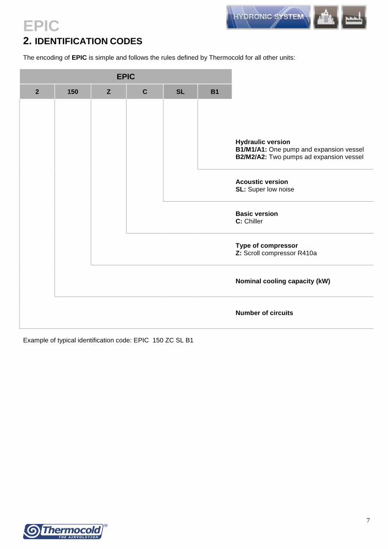
EPIC
7
2 IDENTIFICATION CODES The encoding of EPIC is simple and follows the rules defined by Thermocold for all other units
EPIC
2 150 Z C SL B1
Hydraulic version B1M1A1 One pump and expansion vessel B2M2A2 Two pumps ad expansion vessel
Acoustic version SL Super low noise
Basic version C Chiller
Type of compressor Z Scroll compressor R410a
Nominal cooling capacity (kW)
Number of circuits
Example of typical identification code EPIC 150 ZC SL B1
EPIC
8
3 TECHNICAL SPECIFICATIONS The units belonging to EPIC range are air-water chillers for outdoor installation equipped with inverter scroll compressors and EC axial fans available in 9 sizes and in the following basic version
C Chiller
EPIC units are available in a wide setting up ranges in order to guarantee a high satisfaction level for different plant applications
ACOUSTIC VERIONS (to be associated with the basic version) SL super low noise units The noise reduction is achieved by reduced fans speed in accordance with the condensing pressure muffler on the compressors delivery lines soundproof insulation box for compressors and Axitop diffuser Compared to basic versions SL versions allows a reduction of about 5 dB(A) in sound levels HYDRAULIC VERSIONS (Integrated hydraulic kit available for On-Off pumps andor Inverter pumps) ONE PUMP AND EXPANSION VESSEL B1 Low available pressure 150kPa M1 Medium available pressure 250kPa A1 High available pressure 450kPa TWO PUMPS AD EXPANSION VESSEL B2 Low available pressure 150kPa M2 Medium available pressure 250kPa A2 High available pressure 450kPa CASING Casing made with heavy gauge structure in galvanized steel The powder paint anti-corrosive treatment over the entire frame provides long lasting resistance for outdoor installation even in aggressive environmental conditions Its design allows these machines to be manufactured in modular units and at same time it ensures a constant air flow through the finned coils and makes for easy maintenance and service COMPRESSORS The units are equipped with hermetic scroll compressors with Inverter technology characterized by high performances reduced vibrations and little sound emissions During operation itrsquos developed a more uniform compression and pulsation there are no alternative movements of pistons accompanied by masses or vibration forces to benefit the low noise High performance values are guaranteed by high volumetric efficiency During operation The compressor maintains a supply of power output with limited variations it guaranteed continuous operation of the compressor with limited number of stat and stops than the other type of compressors The inverter technology applied to last generation compressors allows to control and to adapt the speed of the compressor in relation to the set-point Reached the required temperature it is kept constant modulating the power delivered to a minimum ensuring much higher energy saving For this reason it is possible to save energy faster in achieving the desired set-point The temperature of the gas flow is significantly lower thanks to the limited internal heat of the gas aspirated it allows you to work with pressures condensation reduced with more comfort and much long life cycle of the compressor The electric inverter motor cooled by the refrigerant inlet it is equipped with internal thermal protection FANS The technology of ECO-PROFILE ELECTRONIC propeller fans has blades statically and dynamically balanced driven directly by the DC Brushless electric motors closed type external rotor and thermal protection for outdoor installation protected to IP 54 ECO-PROFILE fans are characterized by low speed and ldquoowletrdquo profile to reduce the effect of vortices thereby reducing the energy consumed for operation and noise reducing it by an average of 6dB (A) compared with standard fans The EC fans are also equipped with an integrated control for the continuous modulation of the fans speed according to the condensing pressure allowing minimum power input and ensuring the maximum efficiency of the circuit PLATE HEAT EXCHANGER Direct expansion stainless steel AISI 316 brazed plate type with double circuit externally insulated with closed cell anticondensation material and equipped with water differential pressure switch and antifreeze protection electric heater
EPIC
9
SOURCE HEAT EXCHANGER MICROCHANNELS COILS Air-cooled microchannel condensing coils with aluminum fins The coil is made up of three components the multichannel tubes the fins which are placed between the microchannels and the two refrigerant headers Main features - Reduced consumption and noise level with lower pressure drop in the air side and small size of microchannels condensing coils the turbulence on the condensing coil and pressure drops losses are reduced resulting in reduced noise power andor number of fans needed - Compact the heat transfer surface in contact with the refrigerant is greatly increased so these heat exchangers are more compact and provide higher performance compared to the tube amp fin - Reduced refrigerant charge thanks to new Microchannel technology (heat exchanger) the refrigerant charge is reduced by up to 37 compared to equivalent units with Al-Cu fin amp tube condensers - Reduced emissions of refrigerant into the atmosphere with considerable benefits in terms of environmental protection - Significant reductions in weight which is a double advantage a significant reduction of costs and maintenance time and at the same time lower CO2 emissions in transport Optional coatings are available to protect the coils and to increase the corrosion resistance and for the use in chemical risk environnement REFRIGERANT CIRCUIT The units are equipped with two independent refrigerant circuits entirely constructed with copper tubes each supplied by its own compressor Each circuit includes
bull Refrigerant charge R410a
bull Electronic expansion valve
bull Filter drier with interchangeable cartridge suitable for the use of ecological fluids and polyesters oils
bull Indicator lamp for liquid flow and humidity presence
bull Shut off valve on the liquid line complete of balancing pressure system making easier the opening and closing operations
bull Solenoid valve on the liquid line
bull High pressure switch
bull Low pressure switch
bull Safety valve on the discharge line
bull Safety valve on the suction line
bull High pressure transducers
bull Low pressure transducers ELECTRICAL PANEL The electrical panel made in accordance with CEI-EN 60204-1 (CEI44-5 CEI EN 62061) standards is housed in watertight box the opening system of the box needs the use of a retractable handle or dedicated tools in each case the opening is allowed only after disconnection of the power supply through the main switch with door lock handle lockable in OFF position The electrical panel includes bull Protection fuses for the supply line of each compressor bull Protection fuses for the supply line of fans for each refrigerant circuit bull Protection fuses of auxiliary circuit bull Start up contactors for compressors OnOff (size with tandem Inverter+OnOff) dimensioned according to the maximum stress bull VSD for compressor bull Start up contactors for fans bull Adjustable thermal magnetic circuit breaker for the protection of the pump (only in case of units equipped with hydraulic kit) bull Start up contactors for pump (only in case of units equipped with hydraulic kit) bull single-phase transformer for the power supply of the auxiliary circuits bull numbered wires bull microprocessor control In case of phase failure an automatic system protects fans and compressors The wiring of the electric panel and the connection with the components of the units are made using cables appropriately calculated for operation at 55degC and according to the maximum electrical stress of the components All the cables and the terminals are univocally numbered according to the electrical scheme in order to avoid possible misinterpretation The identification system of the cables connected to the components allow also an easy and intuitive recognition of the component
EPIC
10
Each component of the electrical panel is provided with an identification plate according to what is shown on the electrical scheme All the connection to the electrical panel are made from the bottom and are equipped with cover preventing from break The electrical panel supply is 400V3ph+n50Hz and no additional power supply is necessary The input of the power cables is provided on the bottom of the box where it is provided a dismountable flange suitable for the purpose
POWER AND CONTROL ELECTRICAL PANEL
The units are controlled by one single device that handles all circuits The keypad allows a complete and intuitive display of all the main control variables of both circuits The programmable controller is based on a powerful platform with 256bit microprocessor 4MB mass storage with a hardware and software configuration made with the most innovative technology in terms of processing speed and connectivity The diagnostics includes a complete alarm management alarm history and data logger which stores an archive of about 4 days (further expandable by USB memory) where the main variables and the operating status of the unit are recorded ModBus master and slave communication protocol The temperature regulation us carried out by two hydraulic circuits (cooled water and hot water) with a continuous proportional logic according to the return water temperature The operating parameters of the machine are protected by 3 levels of password (user-maintainer-builder) The user panel provides information LCD dysplay with exhaustive descriptions in Italian and English (selectable)
Ability to interface with the main BMS systems via RS485 BacNet and Lontalk Ability to interface with IO expansion modules via CanBus Ability to control the unit by voltage free contacts Input Ethernet RJ45 for routing on the web of all the parameters of the unit providing a total remote control of
unit USB input to upload parameter files system files firmware and to download files of historical alarms residing
parameters files and default parameters files User interface on the door of the panel low-reflection LCD equipped with 8 function keys easy iconic display
easy sliding between the dynamic screens Control of condensation air through an inverter directly managed by the electronic controller based on
proportional logic Management of electronic expansion valves through controller based on PID logic with LOP control (low
operating pressure) maintenance of the minimum working pressure and of the MOP (maximum operating pressure) for the management of the maximum working pressure
Management of the inverter pump of the cold user side with a continuous proportional signal managed by the electronic
The microprocessor manages Starting of the compressors with the start-up and stop time control Fans start up and modulation according with condensation pressure Solenoid valves of liquid lines with pump-down management during stops through double control of sunction
pressure and maximum time of the procedure Electric anti-freeze heater for user exanchangers Water pumps management through voltage free contacts for standard versions for hydraulic versions the pump
management is automatically controlled General alarm signal for the unit through voltage free contacts
The microprocessor will control and display by suitable measuring transducers the following variables Inlet and outlet water temperature to the user exchanger Outdoor temperature Condensing pressure of each refrigerant circuit Evaporating pressure of each refrigerant circuit Total operating time of each compressor
EPIC
11
Total operating time of the unit The microprocessor will protect the unit in the following cases the resetting of any alarm will always be manual
Low evaporating pressure by analogical and digital input with possibility to edit the marking details High condensing pressure by analogical and digital input High temperature of the compressors windings Reverse rotation of each compressor Low pressure difference between discharge and suction (to allow a correct lubrification of the compressor) with
the possibility to edit the start-up delay and the minimum requested value High pressure difference on the oil filter High temperature of fans motor windings High temperature of pumps motor windings Lack of water flow on evaporator Low evaporator outlet water temperature
It is also possible to display and edit through the microprocessor the following value Operating setpoint of the unit Operating differential of the unit Set point and anti-freeze block differential Set point and differential of activation of the evaporator heater Minimum operating time of each compressor Minimum stop time of each compressor Maximum number of starts per hour of each compressor Set point and optimal condensation pressure differential (condensation control)
Other functionalities ensured from the microprocessor are Activating of preventive functions at extreme conditions of high pressure Activating of preventive functions at extreme conditions of low pressure Activation of preventive functions at limit conditions of high discharge temperature Activating preventive functions at extreme conditions of low evaporator leaving water temperature Activating preventive functions at extreme conditions of high evaporator inlet water temperature Protection from unwanted changes of the parameters thanks of the use of password and systems to confirm the
changed data Indication of the unit status and the components status Possibility to exclude each compressor for the maintenance Possibility to change the set point by external analog signal Possibility of ONOFF remote signal through digital external signal Communication with supervision systems (data and parameters exchange) Continuous adjustment of the set point according to the outdoor air temperature both with direct and reverse
direction logic (DSP) Auto power on-off of the unit using time slots Adjustment of the set point by time bands both with direct and reverse direction logic (Energy Saving)
EPIC
12
4 ACCESSORIES ON DEMAND REGULATION AND CERTIFICATIONS
MOUNTED ACCESSORIES
bull Power factor correction to cos phi 091
bull Control panel electric heater with thermostat
bull Water pumps automatic changeover
bull Phase failure protection relay
bull Serial card with BacNet Protocol MSTP
bull Serial card with BacNet Protocol TCPIP
bull Gateway Modbus Lontalk
bull Soft - Start (only for ON-OFF compressors)
bull Power supply without neutral
bull Automatic circuit breakers(only for ON-OFF compressors)
bull High Static Pressure ECO-PROFILE ELECTRONIC Fans 100 Pa
bull Gas gauges
bull Low outdoor temperature kit up to -10degC (in cooling mode only)
bull Complete anti-intrusion grilles
bull Compressor jackets sound attenuators
bull Powder coated condensing coils
bull Anti-corrosion coated condensing coil
LOOSE ACCESSORIES
bull Remote control display
bull Sea container kit
bull Flow switch
bull Automatic water filling
bull Water strainer
bull Water gauges
bull Victaulic Kit
bull Victaulic adapter
bull Rubber anti vibration mounts
bull Spring antivibration mounts
EPIC
13
CERTIFICATIONS PED RELEASED FROM IMQ SPA - NOTIFIED BODY FOR REGULATION 201468UE (NO 0051) ACCORDING TO
THE FOLLOWING STATEMENTS - DECLARATION OF QUALITY SYSTEM APPROVAL - FORM H1 (QUALITY ASSURANCE WITH DESIGN
CONTROL AND MONITORING OF FINAL CHECK DETAIL) CERTIFICATE N PEC-0051-1105003 - CERTIFICATES OF EXAMINATION OF THE PROJECT N 0051-PEC-110500405060708
ACCORDING TO THE STANDARD QUALITY CERTIFICATION UNI EN ISO 90012008 ISSUED BY CSQ (ACCREDITED
ACCREDIA) CERTIFICATION OF PERFORMANCE UNIT BY MEANS OF TESTING TO PRESENT WHEN THE THIRD BODY - RINA
SPA (OPTIONAL) GOST - (OPTIONAL) FOR PRESSURE RECIPIENTS OF THE RUSSIAN FEDERATION
REFERENCE STANDARD THE PRESSURE EQUIPMENT DIRECTIVE 201468UE UNI EN ISO 3744 ACOUSTIC REGULATION UNI-EN-ISO 90012008 QUALITY MANAGEMENT SYSTEMS LOW VOLTAGE DIRECTIVE (LVD) 201435UE MACHINERY DIRECTIVE 200642EC DIRECTIVE FOR ELECTROMAGNETIC COMPATIBILITY 201430EU CEI-EN 60204-1 DIRECTIVE (CEI44-5 CEI EN 62061) MACHINERY SAFETY ndash ELECTRIC MACHINERY ndash EQUIPMENTS ERP DIRECTIVE (ENERGY-RELATED-PRODUCTS ECODESIGN 2009125CE) UNI EN 14511-1-2-3-4 TESTING CONDITIONS
EPIC
14
5 TECHNICAL DATA GENERAL TECHNICAL DATA EPIC
MODELLO 150 ZC 170 ZC 180 ZC 1115 ZC
Cooling (1)
Total cooling capacity kW 484 6778 809 114
Compressors power input kW 130 200 221 310
Total EER 302 295 304 308
ESEER 441 447 451 449
EER CLASS B B B B
Water flow msup3h 83 117 139 196
Water pressure drop kPa 305 264 359 237
COMPRESSORS
Compressors number n 1 1 2 2
Refrigerant circuits n 1 1 1 1
Part load n INVERTER REGULATION 15-100
Refrigerant charge kg 80 84 123 165
Oil charge dm^3 36 67 69 134
FANS
Fans number n 2 2 3 4
Air flow msup3h 35200 35200 52800 70400
Power input for each fan kW 15 15 15 15
Absorbed current for each fan A 3 3 3 3
SOUND LEVEL
Sound power level (ISO 3744) dB(A) 87 92 88 93
Sound pressure level at 10 m (ISO 3744) dB(A) 55 60 56 61
DIMENSIONS AND WEIGHT
Length mm 2461 2461 3599 2257
Deepth mm 1100 1100 1100 2146
Height mm 2179 2179 2179 2175
Operanting Weight kg 598 657 954 1226
Shipping Weight kg 593 652 946 1218
(1) Outdoor air temperature 35 degC ndash Outlet water temperature 127 degC
EPIC
15
GENERAL TECHNICAL DATA
EPIC
MODELLO 2135 ZC 2150 ZC 2185 ZC 2215 ZC 2230 ZC
Cooling (1)
Total cooling capacity kW 134 151 183 214 232
Compressors power input kW 393 414 479 599 664
Total EER 297 299 305 298 296
ESEER 427 427 418 411 424
EER CLASS B B B B B
Water flow msup3h 231 260 315 368 399
Water pressure drop kPa 290 342 295 424 383
COMPRESSORS
Compressors number n 2 4 4 4 4
Refrigerant circuits n 2 2 2 2 2
Part load n INVERTER REGULATION 15-100
Refrigerant charge kg 166 239 321 321 325
Oil charge dm^3 134 138 144 206 268
FANS
Fans number n 4 6 8 8 8
Air flow msup3h 70400 105600 140800 140800 140800
Power input for each fan kW 15 15 15 15 15
Absorbed current for each fan A 3 3 3 3 3
SOUND LEVEL
Sound power level (ISO 3744) dB(A) 95 91 92 94 96
Sound pressure level at 10 m (ISO 3744) dB(A) 63 59 60 62 64
DIMENSIONS AND WEIGHT
Length mm 2257 3421 4550 4550 4550
Deepth mm 2146 2138 2244 2244 2244
Height mm 2175 2469 2458 2458 2458
Operanting Weight kg 1283 1897 2297 2421 2543
Shipping Weight kg 1270 1884 2280 2404 2522
(1) Outdoor air temperature 35 degC ndash Outlet water temperature 127 degC
EPIC
16
GENERAL TECHNICAL DATA
EPIC SL
MODELLO 150 ZC 170 ZC 180 ZC 1115 ZC
Cooling (1)
Total cooling capacity kW 477 650 793 110
Compressors power input kW 139 210 235 328
Total EER 317 293 316 314
ESEER 458 463 471 479
EER CLASS A B A A
Water flow msup3h 82 112 136 189
Water pressure drop kPa 296 243 345 221
COMPRESSORS
Compressors number n 1 1 2 2
Refrigerant circuits n 1 1 1 1
Part load n INVERTER REGULATION 15-100
Refrigerant charge kg 80 84 123 165
Oil charge dm^3 36 67 69 134
FANS
Fans number n 2 2 3 4
Air flow msup3h 24640 24640 36960 49280
Power input for each fan kW 055 055 055 055
Absorbed current for each fan A 11 11 11 11
SOUND LEVEL
Sound power level (ISO 3744) dB(A) 82 87 83 88
Sound pressure level at 10 m (ISO 3744) dB(A) 50 55 51 56
DIMENSIONS AND WEIGHT
Length mm 2461 2461 3599 2257
Deepth mm 1100 1100 1100 2146
Height mm 2179 2179 2179 2175
Operanting Weight kg 782 841 1192 1518
Shipping Weight kg 777 836 1181 1510
(1) Outdoor air temperature 35 degC ndash Outlet water temperature 127 degC
EPIC
17
GENERAL TECHNICAL DATA
EPIC SL
MODELLO 2135 ZC 2150 ZC 2185 ZC 2215 ZC 2230 ZC
Cooling (1)
Total cooling capacity kW 130 144 181 210 222
Compressors power input kW 413 453 514 639 709
Total EER 299 297 324 307 295
ESEER 417 419 425 429 415
EER CLASS B B A B B
Water flow msup3h 223 249 311 361 382
Water pressure drop kPa 270 314 289 408 351
COMPRESSORS
Compressors number n 2 4 4 4 4
Refrigerant circuits n 2 2 2 2 2
Part load n INVERTER REGULATION 15-100
Refrigerant charge kg 166 239 321 321 325
Oil charge dm^3 134 138 144 206 268
FANS
Fans number n 4 6 8 8 8
Air flow msup3h 49280 73920 98560 98560 98560
Power input for each fan kW 055 055 055 055 055
Absorbed current for each fan A 11 11 11 11 11
SOUND LEVEL
Sound power level (ISO 3744) dB(A) 90 86 86 89 91
Sound pressure level at 10 m (ISO 3744) dB(A) 58 53 54 57 59
DIMENSIONS AND WEIGHT
Length mm 2257 3421 4550 4550 4550
Deepth mm 2146 2138 2244 2244 2244
Height mm 2175 2469 2458 2458 2458
Operanting Weight kg 1651 2373 2881 3005 3127
Shipping Weight kg 1638 2360 2864 2988 3106
(1) Outdoor air temperature 35 degC ndash Outlet water temperature 127 degC
EPIC
18
6 OPERATING RANGE
Version Operating way Ta Tw out
Min Max Min Max
C Cooling -10(2) 47 -6 (1) 18
(1) Operation with glycol (2) Only with Low Outodoor Temperature kit (optional) Ta = Outdoor air temperature (degC)
Tw out = Outlet water temperature (degC)
EPIC
19
7 SCALING CORRECTION SCHEDULES
FOULING FACTOR CORRECTION TABLE
Fouling Factor Plant side cold heat exchanger
FF A1 B1 Tmin
[m^2degCW]
0 100 100 000
180E-05 100 100 000
440E-05 100 100 000
880E-05 096 099 070
132E-04 094 099 100
172E-04 093 098 150
A factor Capacity correction factor B factor Compressor power input correction factor Tmin Minimum evaporator outlet water temperature increase
T max Maximum condenser outlet water temperature descrease
EPIC
20
8 HYDRAULIC DATA WATER FLOW AND RECOMMENDED WATER CONTENT OF THE PLANT
EPIC
Plant side Cold Heat Exchanger
COOLING Vminimo Vottimale K Q min Q max
P Q dpw [m3] [m3]
[m3h] [m3h]
150 ZC 484 832 305 02 03 440 52 139
170 ZC 678 1166 264 03 04 1942 73 194
180 ZC 809 1391 359 04 05 1854 87 232
1115 ZC 114 1957 237 05 07 619 122 326
2135 ZC 134 2312 29 06 09 542 145 385
2150 ZC 151 2597 342 07 1 508 162 433
2185 ZC 183 3146 295 08 12 298 197 524
2215 ZC 214 3683 424 1 14 313 23 614
2230 ZC 232 3993 383 11 15 24 25 666
150 ZC SL 477 82 296 02 03 4398 51 137
170 ZC SL 65 1118 243 03 04 1942 7 186
180 ZC SL 793 1364 345 04 05 1854 85 227
1115 ZC SL 110 1889 221 05 07 619 118 315
2135 ZC SL 130 2232 27 06 08 542 14 372
2150 ZC SL 144 2485 314 07 09 508 155 414
2185 ZC SL 181 3113 289 08 12 298 195 519
2215 ZC SL 210 3612 408 1 13 313 226 602
2230 ZC SL 222 3824 351 1 14 24 239 637
V recommended water content of the plant (cold side and hot side) with dT 5 deg C on the heat exchanger
Q min minimum water flow admitted to the excharger
Q max maximum water flow admitted to the excharger
dPw = KQ2 1000
P Heating capacity [kW]
Δt ΔT at heat exchange (min =3 max = 8) [degC]
Dpw Pressure drop [kPa]
EPIC
21
HYDRAULIC VERSIONS The units of the EPIC family are also available in multiple hydraulic versions characterized by complete kits of all major hydraulic components for an easier installation with reduced time cost and space The wide range of hydraulic versions available make the unit suitable for any type of installation HYDRAULIC VERSIONS (Integrated hydraulic kit available for On-Off pumps andor Inverter pumps) B1M1A1 One pump and expansion vessel B2M2A2 Two pumps ad expansion vessel
Centrifugal pumps with 2 poles axial suction bowls and radial delivery available in low medium or high head pressure Pumps with cast iron body and impeller entirely welded usinjg laser technology Mechanical seal with ceramic components coal and EPDM elastomers Three phase electric motor with IP55 protection and insulation class F suitable for continuous service Series motors with higher efficiency IE3 technology bull Differential pressure switch on exchanger bull Service valve bull Taps on pumps suction delivery which allow the replacement of a damaged pump eliminating the plant shutdown differently from other types of common use bull Check valve bull Relief valve bull Discharge valve The water pumps automatic changeover for hydraulic versions equipped with two pumps is also available as optional The pumps operate with the balance of the related working hours In case of failure of one pump the controller in automatic switches on the additional pump The control panel is equipped with fuses and contactor with thermal protection HYDRONIC ACCESORIES ON REQUEST bull Water pumps automatic changeover for 2 pumps hydraulic kits which also includes the secondary pump pressure switch bull ldquoYrdquo water strainer (sold separately) consists of body and stainless steel mesh with replaceable filter through the inspection cap bull Automatic water filling (sold separately)
EPIC
22
LOW HEAD PRESSURE PUMP (150 kPa)
COOLING ONLY MODE
Model Pf qw dpw Rif Curve Expansion vessel
On-off Pumps Hp Hu
FLI FLA
[kW] [m^3h] [kPa]
[l] [kW] [A] [kPa] [kPa]
150 484 83 305 A 5 177 330 212 181
170 68 117 264 A 5 177 330 193 166
180 81 139 359 B 5 178 380 190 154
1115 114 196 237 C 5 255 470 209 185
2135 134 231 290 C 12 255 470 209 180
2150 151 260 342 D 12 344 640 214 180
2185 183 315 295 D 12 344 640 194 164
2215 214 368 424 E 12 452 870 244 201
2230 232 399 383 E 12 452 870 239 200
Pf Cooling capacity (kW) qw Water flow (m3h) dpw Pressure drop (kPa) FLI Full load electrical power input FLA Full load operating current Hp Pump Head pressure Hu Available head pressure
EPIC
23
MEDIUM HEAD PRESSURE PUMP (250 kPa)
COOLING ONLY MODE
Model Pf qw dpw Rif Curve Expansion vessel
On-off Pumps Hp Hu
FLI FLA
[kW] [m^3h] [kPa]
[l] [kW] [A] [kPa] [kPa]
150 484 83 305 F 5 255 470 333 303
170 68 117 264 F 5 255 470 313 287
180 81 139 359 F 5 255 470 297 261
1115 114 196 237 G 5 452 870 349 325
2135 134 231 290 G 12 452 870 337 308
2150 151 260 342 G 12 452 870 326 292
2185 183 315 295 H 12 610 1060 313 284
2215 214 368 424 H 12 610 1060 304 261
2230 232 399 383 H 12 610 1060 297 259
Pf Cooling capacity (kW) qw Water flow (m3h) dpw Pressure drop (kPa) FLI Full load electrical power input FLA Full load operating current Hp Pump Head pressure Hu Available head pressure
EPIC
24
HIGH HEAD PRESSURE PUMP (450 kPa)
COOLING ONLY MODE
Model Pf qw dpw Rif Curve Expansion vessel
On-off Pumps Hp Hu
FLI FLA
[kW] [m^3h] [kPa]
[l] [kW] [A] [kPa] [kPa]
150 484 83 305 I 5 425 87 494 463
170 68 117 264 I 5 425 87 473 446
180 81 139 359 I 5 425 87 455 419
1115 114 196 237 L 5 826 136 543 519
2135 134 231 290 L 12 826 136 528 499
2150 151 260 342 L 12 826 136 514 480
2185 183 315 295 L 12 826 136 533 503
2215 214 368 424 M 12 1198 213 520 478
2230 232 399 383 M 12 1198 213 512 474
Pf Cooling capacity (kW) qw Water flow (m3h) dpw Pressure drop (kPa) FLI Full load electrical power input FLA Full load operating current Hp Pump Head pressure Hu Available head pressure
EPIC
25
CONNECTION SCHEME - STANDARD VERSION
Note a water strainer shall always be installed on the inlet water pipe
EPIC
26
HYDRONIC KIT WITH 1 PUMP ndash B1M1A1
Note a water strainer shall always be installed on the inlet water pipe
EPIC
27
HYDRONIC KIT WITH 2 PUMPS - B2M2A2
Note a water strainer shall always be installed on the inlet water pipe
EPIC
28
9 ELECTRICAL DATA
EPIC
NOMINAL VALUES MAXIMUM VALUES (1)
Outdoor air temperature 35degC evaporator water temperature inout 127degC
Model
Compressors (2) Fans TOTAL TOTAL
FLI FLA LRA EP OC FLI FLA SA FLI FLA SA
kW A A kW A kW A A kW A A
150 ZC 130 222 550 30 60 160 282 610 230 410 610
170 ZC 200 298 763 30 60 230 358 823 313 556 823
180 ZC 221 395 1470 45 90 266 485 1730 375 667 1787
1115 ZC 310 516 1700 60 120 370 636 2053 509 905 2109
2135 ZC 393 596 763 60 120 453 716 1181 627 1112 1379
2150 ZC 414 792 1470 90 180 504 972 2216 749 1334 2454
2185 ZC 479 865 1970 120 240 599 1105 2854 855 1526 3146
2215 ZC 599 1009 2150 120 240 719 1249 3113 987 1757 3529
2230 ZC 664 1148 2600 120 240 784 1388 3653 1118 1987 4121
EPIC SL
NOMINAL VALUES
MAXIMUM VALUES (1) Outdoor air temperature 35degC evaporator water temperature inout 127degC
Model
Compressors (2) Fans TOTAL TOTAL
FLI FLA LRA EP OC FLI FLA SA FLI FLA SA
kW A A kW A kW A A kW A A
150 ZC 139 224 550 11 22 150 246 572 230 410 610
170 ZC 210 301 763 11 22 221 323 785 313 556 823
180 ZC 234 398 1470 17 33 251 431 1674 375 667 1787
1115 ZC 328 520 1700 22 44 350 564 1978 509 905 2109
2135 ZC 413 601 763 22 44 435 645 1108 627 1112 1379
2150 ZC 453 797 1470 33 66 486 863 2106 749 1334 2454
2185 ZC 514 871 1970 44 88 558 959 2706 855 1526 3146
2215 ZC 639 1017 2150 44 88 683 1105 2967 987 1757 3529
2230 ZC 709 1157 2600 44 88 753 1245 3508 1118 1987 4121
Electrical data referred to 400V - 3PH+N-50Hz Maximum operating admitted conditions 10 Maximum phase unbalance 3 FLI full load electrical power with max thermal load FLA full load operating current with max thermal load LRA compressor motor locked rotor current (direct starting) SA sum of LRA of the most powerful compressor FLA of other compressor and fans current EP electrical power OC operating current
(1) Values to be considered in the sizing of the power cables and line protection (2) Data referred to the biggest compressor for units with different compressors
EPIC
29
10 ACOUSTIC DATA EPIC
Model
Octave Band (Hz) Lw (db(A)
63 125 250 500 1000 2000 4000 8000
Sound power level (dB)
150 Z 645 605 559 517 493 645 470 360 87
170 Z 695 655 609 567 543 695 520 410 92
180 Z 653 613 567 525 501 653 478 368 88
1115 Z 704 664 618 576 552 704 529 419 93
2135 Z 724 684 638 596 572 724 549 439 95
2150 Z 682 642 596 554 530 682 507 397 91
2185 Z 690 650 604 562 538 690 515 405 92
2215 Z 710 670 624 582 558 710 535 425 94
2230 Z 730 690 644 602 578 730 555 445 96 NOTE The data reported in the table refer to units without the hydraulic version
EPIC SL
Model
Octave Band (Hz) Lw (db(A)
63 125 250 500 1000 2000 4000 8000
Sound power level (dB)
150 Z 595 555 509 467 443 595 420 310 82
170 Z 645 605 559 517 493 645 470 360 87
180 Z 603 563 517 475 451 603 428 318 83
1115 Z 654 614 568 526 502 654 479 369 88
2135 Z 674 634 588 546 522 674 499 389 90
2150 Z 632 592 546 504 480 632 457 347 86
2185 Z 640 600 554 512 488 640 465 355 87
2215 Z 660 620 574 532 508 660 485 375 89
2230 Z 680 640 594 552 528 680 505 395 91 NOTE The data reported in the table refer to units without the hydraulic version
EPIC
30
NOISE CORRECTION FACTORS FOR HYDRAULIC VERSION
For the Hydraulic version please consider the noise output increase due to the addition of the hydraulic group EPIC
Modelli
bassa prevalenza media prevalenza alta prevalenza
1 pompa 2 pompe 1 pompa 2 pompe 1 pompa 2 pompe
[dB(A)] [dB(A)] [dB(A)] [dB(A)] [dB(A)] [dB(A)]
150 ZC 03 03 04 04 08 08
170 ZC 01 01 01 01 03 03
180 ZC 02 02 04 04 07 07
1115 ZC 01 01 02 02 05 05
2135 ZC 01 01 02 02 03 03
2150 ZC 03 03 04 04 08 08
2185 ZC 02 02 04 04 06 06
2215 ZC 02 02 03 03 07 07
2230 ZC 01 01 02 02 04 04
EPIC SL
Modelli
bassa prevalenza media prevalenza alta prevalenza
1 pompa 2 pompe 1 pompa 2 pompe 1 pompa 2 pompe
[dB(A)] [dB(A)] [dB(A)] [dB(A)] [dB(A)] [dB(A)]
150 ZC 08 08 13 13 22 22
170 ZC 03 03 04 04 08 08
180 ZC 07 07 10 10 18 18
1115 ZC 04 04 07 07 15 15
2135 ZC 02 02 05 05 10 10
2150 ZC 08 08 11 11 21 21
2185 ZC 08 08 15 15 21 21
2215 ZC 06 06 08 08 18 18
2230 ZC 04 04 06 06 12 12
Operating conditions Outlet water temperature inout 12degC7degC ndash outdoor air temperature 35degC Testing point Average sound pressure levels calculated according to ISO 9614 at 10 mt distance from unit Measurement conditions Free field on reflecting surface (Q factor Q=2)
bull For units installed in the presence of 2 reflecting surfaces (Q factor Q=4) 3 dB have to be added at values above mentioned bull For units installed in the presence of 3 reflecting surfaces (Q factor Q=8) 6 dB have to be added at values above mentioned bull For units installed at a certain height from the ground the sound energy coming out from the bottom of the unit leads an increase of the noise pressure level of around 3 dB
Sound emission values in octave bands are shown just as an indication and they are not to be considered as a commitment Sound pressure values according to ISO 3744 standards and in observance of EUROVENT certification program are the only ones to be used for every calculation to make a prevision of the sound pressure level at the operating conditions The sound pressure level data are not binding For a more precise value please refer to the sound power level
EPIC
31
11 DIMENSIONAL DRAWINGS AND WEIGHTS
EPIC - BASIC VERSION
150 ZC divide 170 ZC
EPIC
32
150 ZC divide 170 ZC + B1M1A1- B2M2A2
EPIC
33
180 ZC
EPIC
34
180 ZC + B1M1A1- B2M2A2
EPIC
35
1115 ZC divide 2135 ZC
EPIC
36
1115 ZC divide 2135 ZC + B1M1A1- B2M2A2
EPIC
37
2150 ZC
EPIC
38
2150 ZC+ B1M1A1- B2M2A2
EPIC
39
2185 ZC - 2230 ZC
EPIC
40
2185 ZC - 2230 ZC + B1M1A1- B2M2A2
EPIC
41
EPIC - SUPER LOW NOISE VERSION
150 ZC SL divide 170 ZC SL
EPIC
42
150 ZC SL divide 170 ZC SL + B1M1A1- B2M2A2
EPIC
43
180 ZC SL
EPIC
44
180 ZC SL + B1M1A1- B2M2A2
EPIC
45
1115 ZC SL divide 2135 ZC SL
EPIC
46
1115 ZC SL divide 2135 ZC SL + B1M1A1- B2M2A2
EPIC
47
2150 ZC SL
EPIC
48
2150 ZC SL + B1M1A1- B2M2A2
EPIC
49
2185 ZC SL - 2230 ZC SL
EPIC
50
2185 ZC SL - 2230 ZC SL + B1M1A1- B2M2A2
EPIC
51
OPERATION AND SHIPPING WEIGHTS
Operation weights 150 ZC 170 ZC 180 ZC 1115 ZC 2135 ZC 2150 ZC 2185 ZC 2215 ZC 2230 ZC
Basic Version kg 598 657 954 1226 1283 1897 2297 2421 2543
1 Pump - Low head pressure kg 32 32 23 26 26 31 31 74 74
2 Pumps - Low head pressure kg 60 60 43 49 49 58 58 140 140
1 Pump - Medium Head pressure kg 55 55 55 74 74 74 93 93 93
2 Pumps - Medium head pressure kg 104 104 104 140 140 140 176 176 176
1 Pump - High head pressure kg 77 77 77 102 102 102 102 127 127
2 Pumps - High head pressure kg 146 146 146 193 193 193 193 241 241
Increase for version
Super low Noise kg 184 184 238 292 368 476 584 584 584
Shipping weights
150 ZC 170 ZC 180 ZC 1115 ZC 2135 ZC 2150 ZC 2185 ZC 2215 ZC 2230 ZC
Basic Version kg 593 652 943 1218 1270 1884 2280 2404 2522
1 Pump - Low head pressure kg 32 32 23 26 26 31 31 74 74
2 Pumps - Low head pressure kg 60 60 43 49 49 58 58 140 140
1 Pump - Medium Head pressure kg 55 55 55 74 74 74 93 93 93
2 Pumps - Medium head pressure kg 104 104 104 140 140 140 176 176 176
1 Pump - High head pressure kg 77 77 77 102 102 102 102 127 127
2 Pumps - High head pressure kg 146 146 146 193 193 193 193 241 241
Increase for version
Super low Noise kg 184 184 238 292 368 476 584 584 584
Technical data and dimensions are not binding Thermocold reserves the right to make necessary changes without notice
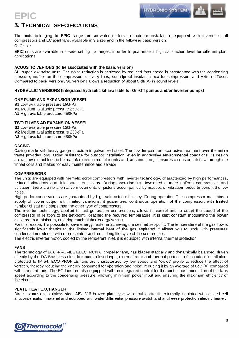
EPIC
21
HYDRAULIC VERSIONS The units of the EPIC family are also available in multiple hydraulic versions characterized by complete kits of all major hydraulic components for an easier installation with reduced time cost and space The wide range of hydraulic versions available make the unit suitable for any type of installation HYDRAULIC VERSIONS (Integrated hydraulic kit available for On-Off pumps andor Inverter pumps) B1M1A1 One pump and expansion vessel B2M2A2 Two pumps ad expansion vessel
Centrifugal pumps with 2 poles axial suction bowls and radial delivery available in low medium or high head pressure Pumps with cast iron body and impeller entirely welded usinjg laser technology Mechanical seal with ceramic components coal and EPDM elastomers Three phase electric motor with IP55 protection and insulation class F suitable for continuous service Series motors with higher efficiency IE3 technology bull Differential pressure switch on exchanger bull Service valve bull Taps on pumps suction delivery which allow the replacement of a damaged pump eliminating the plant shutdown differently from other types of common use bull Check valve bull Relief valve bull Discharge valve The water pumps automatic changeover for hydraulic versions equipped with two pumps is also available as optional The pumps operate with the balance of the related working hours In case of failure of one pump the controller in automatic switches on the additional pump The control panel is equipped with fuses and contactor with thermal protection HYDRONIC ACCESORIES ON REQUEST bull Water pumps automatic changeover for 2 pumps hydraulic kits which also includes the secondary pump pressure switch bull ldquoYrdquo water strainer (sold separately) consists of body and stainless steel mesh with replaceable filter through the inspection cap bull Automatic water filling (sold separately)
EPIC
22
LOW HEAD PRESSURE PUMP (150 kPa)
COOLING ONLY MODE
Model Pf qw dpw Rif Curve Expansion vessel
On-off Pumps Hp Hu
FLI FLA
[kW] [m^3h] [kPa]
[l] [kW] [A] [kPa] [kPa]
150 484 83 305 A 5 177 330 212 181
170 68 117 264 A 5 177 330 193 166
180 81 139 359 B 5 178 380 190 154
1115 114 196 237 C 5 255 470 209 185
2135 134 231 290 C 12 255 470 209 180
2150 151 260 342 D 12 344 640 214 180
2185 183 315 295 D 12 344 640 194 164
2215 214 368 424 E 12 452 870 244 201
2230 232 399 383 E 12 452 870 239 200
Pf Cooling capacity (kW) qw Water flow (m3h) dpw Pressure drop (kPa) FLI Full load electrical power input FLA Full load operating current Hp Pump Head pressure Hu Available head pressure
EPIC
23
MEDIUM HEAD PRESSURE PUMP (250 kPa)
COOLING ONLY MODE
Model Pf qw dpw Rif Curve Expansion vessel
On-off Pumps Hp Hu
FLI FLA
[kW] [m^3h] [kPa]
[l] [kW] [A] [kPa] [kPa]
150 484 83 305 F 5 255 470 333 303
170 68 117 264 F 5 255 470 313 287
180 81 139 359 F 5 255 470 297 261
1115 114 196 237 G 5 452 870 349 325
2135 134 231 290 G 12 452 870 337 308
2150 151 260 342 G 12 452 870 326 292
2185 183 315 295 H 12 610 1060 313 284
2215 214 368 424 H 12 610 1060 304 261
2230 232 399 383 H 12 610 1060 297 259
Pf Cooling capacity (kW) qw Water flow (m3h) dpw Pressure drop (kPa) FLI Full load electrical power input FLA Full load operating current Hp Pump Head pressure Hu Available head pressure
EPIC
24
HIGH HEAD PRESSURE PUMP (450 kPa)
COOLING ONLY MODE
Model Pf qw dpw Rif Curve Expansion vessel
On-off Pumps Hp Hu
FLI FLA
[kW] [m^3h] [kPa]
[l] [kW] [A] [kPa] [kPa]
150 484 83 305 I 5 425 87 494 463
170 68 117 264 I 5 425 87 473 446
180 81 139 359 I 5 425 87 455 419
1115 114 196 237 L 5 826 136 543 519
2135 134 231 290 L 12 826 136 528 499
2150 151 260 342 L 12 826 136 514 480
2185 183 315 295 L 12 826 136 533 503
2215 214 368 424 M 12 1198 213 520 478
2230 232 399 383 M 12 1198 213 512 474
Pf Cooling capacity (kW) qw Water flow (m3h) dpw Pressure drop (kPa) FLI Full load electrical power input FLA Full load operating current Hp Pump Head pressure Hu Available head pressure
EPIC
25
CONNECTION SCHEME - STANDARD VERSION
Note a water strainer shall always be installed on the inlet water pipe
EPIC
26
HYDRONIC KIT WITH 1 PUMP ndash B1M1A1
Note a water strainer shall always be installed on the inlet water pipe
EPIC
27
HYDRONIC KIT WITH 2 PUMPS - B2M2A2
Note a water strainer shall always be installed on the inlet water pipe
EPIC
28
9 ELECTRICAL DATA
EPIC
NOMINAL VALUES MAXIMUM VALUES (1)
Outdoor air temperature 35degC evaporator water temperature inout 127degC
Model
Compressors (2) Fans TOTAL TOTAL
FLI FLA LRA EP OC FLI FLA SA FLI FLA SA
kW A A kW A kW A A kW A A
150 ZC 130 222 550 30 60 160 282 610 230 410 610
170 ZC 200 298 763 30 60 230 358 823 313 556 823
180 ZC 221 395 1470 45 90 266 485 1730 375 667 1787
1115 ZC 310 516 1700 60 120 370 636 2053 509 905 2109
2135 ZC 393 596 763 60 120 453 716 1181 627 1112 1379
2150 ZC 414 792 1470 90 180 504 972 2216 749 1334 2454
2185 ZC 479 865 1970 120 240 599 1105 2854 855 1526 3146
2215 ZC 599 1009 2150 120 240 719 1249 3113 987 1757 3529
2230 ZC 664 1148 2600 120 240 784 1388 3653 1118 1987 4121
EPIC SL
NOMINAL VALUES
MAXIMUM VALUES (1) Outdoor air temperature 35degC evaporator water temperature inout 127degC
Model
Compressors (2) Fans TOTAL TOTAL
FLI FLA LRA EP OC FLI FLA SA FLI FLA SA
kW A A kW A kW A A kW A A
150 ZC 139 224 550 11 22 150 246 572 230 410 610
170 ZC 210 301 763 11 22 221 323 785 313 556 823
180 ZC 234 398 1470 17 33 251 431 1674 375 667 1787
1115 ZC 328 520 1700 22 44 350 564 1978 509 905 2109
2135 ZC 413 601 763 22 44 435 645 1108 627 1112 1379
2150 ZC 453 797 1470 33 66 486 863 2106 749 1334 2454
2185 ZC 514 871 1970 44 88 558 959 2706 855 1526 3146
2215 ZC 639 1017 2150 44 88 683 1105 2967 987 1757 3529
2230 ZC 709 1157 2600 44 88 753 1245 3508 1118 1987 4121
Electrical data referred to 400V - 3PH+N-50Hz Maximum operating admitted conditions 10 Maximum phase unbalance 3 FLI full load electrical power with max thermal load FLA full load operating current with max thermal load LRA compressor motor locked rotor current (direct starting) SA sum of LRA of the most powerful compressor FLA of other compressor and fans current EP electrical power OC operating current
(1) Values to be considered in the sizing of the power cables and line protection (2) Data referred to the biggest compressor for units with different compressors
EPIC
29
10 ACOUSTIC DATA EPIC
Model
Octave Band (Hz) Lw (db(A)
63 125 250 500 1000 2000 4000 8000
Sound power level (dB)
150 Z 645 605 559 517 493 645 470 360 87
170 Z 695 655 609 567 543 695 520 410 92
180 Z 653 613 567 525 501 653 478 368 88
1115 Z 704 664 618 576 552 704 529 419 93
2135 Z 724 684 638 596 572 724 549 439 95
2150 Z 682 642 596 554 530 682 507 397 91
2185 Z 690 650 604 562 538 690 515 405 92
2215 Z 710 670 624 582 558 710 535 425 94
2230 Z 730 690 644 602 578 730 555 445 96 NOTE The data reported in the table refer to units without the hydraulic version
EPIC SL
Model
Octave Band (Hz) Lw (db(A)
63 125 250 500 1000 2000 4000 8000
Sound power level (dB)
150 Z 595 555 509 467 443 595 420 310 82
170 Z 645 605 559 517 493 645 470 360 87
180 Z 603 563 517 475 451 603 428 318 83
1115 Z 654 614 568 526 502 654 479 369 88
2135 Z 674 634 588 546 522 674 499 389 90
2150 Z 632 592 546 504 480 632 457 347 86
2185 Z 640 600 554 512 488 640 465 355 87
2215 Z 660 620 574 532 508 660 485 375 89
2230 Z 680 640 594 552 528 680 505 395 91 NOTE The data reported in the table refer to units without the hydraulic version
EPIC
30
NOISE CORRECTION FACTORS FOR HYDRAULIC VERSION
For the Hydraulic version please consider the noise output increase due to the addition of the hydraulic group EPIC
Modelli
bassa prevalenza media prevalenza alta prevalenza
1 pompa 2 pompe 1 pompa 2 pompe 1 pompa 2 pompe
[dB(A)] [dB(A)] [dB(A)] [dB(A)] [dB(A)] [dB(A)]
150 ZC 03 03 04 04 08 08
170 ZC 01 01 01 01 03 03
180 ZC 02 02 04 04 07 07
1115 ZC 01 01 02 02 05 05
2135 ZC 01 01 02 02 03 03
2150 ZC 03 03 04 04 08 08
2185 ZC 02 02 04 04 06 06
2215 ZC 02 02 03 03 07 07
2230 ZC 01 01 02 02 04 04
EPIC SL
Modelli
bassa prevalenza media prevalenza alta prevalenza
1 pompa 2 pompe 1 pompa 2 pompe 1 pompa 2 pompe
[dB(A)] [dB(A)] [dB(A)] [dB(A)] [dB(A)] [dB(A)]
150 ZC 08 08 13 13 22 22
170 ZC 03 03 04 04 08 08
180 ZC 07 07 10 10 18 18
1115 ZC 04 04 07 07 15 15
2135 ZC 02 02 05 05 10 10
2150 ZC 08 08 11 11 21 21
2185 ZC 08 08 15 15 21 21
2215 ZC 06 06 08 08 18 18
2230 ZC 04 04 06 06 12 12
Operating conditions Outlet water temperature inout 12degC7degC ndash outdoor air temperature 35degC Testing point Average sound pressure levels calculated according to ISO 9614 at 10 mt distance from unit Measurement conditions Free field on reflecting surface (Q factor Q=2)
bull For units installed in the presence of 2 reflecting surfaces (Q factor Q=4) 3 dB have to be added at values above mentioned bull For units installed in the presence of 3 reflecting surfaces (Q factor Q=8) 6 dB have to be added at values above mentioned bull For units installed at a certain height from the ground the sound energy coming out from the bottom of the unit leads an increase of the noise pressure level of around 3 dB
Sound emission values in octave bands are shown just as an indication and they are not to be considered as a commitment Sound pressure values according to ISO 3744 standards and in observance of EUROVENT certification program are the only ones to be used for every calculation to make a prevision of the sound pressure level at the operating conditions The sound pressure level data are not binding For a more precise value please refer to the sound power level
EPIC
31
11 DIMENSIONAL DRAWINGS AND WEIGHTS
EPIC - BASIC VERSION
150 ZC divide 170 ZC
EPIC
32
150 ZC divide 170 ZC + B1M1A1- B2M2A2
EPIC
33
180 ZC
EPIC
34
180 ZC + B1M1A1- B2M2A2
EPIC
35
1115 ZC divide 2135 ZC
EPIC
36
1115 ZC divide 2135 ZC + B1M1A1- B2M2A2
EPIC
37
2150 ZC
EPIC
38
2150 ZC+ B1M1A1- B2M2A2
EPIC
39
2185 ZC - 2230 ZC
EPIC
40
2185 ZC - 2230 ZC + B1M1A1- B2M2A2
EPIC
41
EPIC - SUPER LOW NOISE VERSION
150 ZC SL divide 170 ZC SL
EPIC
42
150 ZC SL divide 170 ZC SL + B1M1A1- B2M2A2
EPIC
43
180 ZC SL
EPIC
44
180 ZC SL + B1M1A1- B2M2A2
EPIC
45
1115 ZC SL divide 2135 ZC SL
EPIC
46
1115 ZC SL divide 2135 ZC SL + B1M1A1- B2M2A2
EPIC
47
2150 ZC SL
EPIC
48
2150 ZC SL + B1M1A1- B2M2A2
EPIC
49
2185 ZC SL - 2230 ZC SL
EPIC
50
2185 ZC SL - 2230 ZC SL + B1M1A1- B2M2A2
EPIC
51
OPERATION AND SHIPPING WEIGHTS
Operation weights 150 ZC 170 ZC 180 ZC 1115 ZC 2135 ZC 2150 ZC 2185 ZC 2215 ZC 2230 ZC
Basic Version kg 598 657 954 1226 1283 1897 2297 2421 2543
1 Pump - Low head pressure kg 32 32 23 26 26 31 31 74 74
2 Pumps - Low head pressure kg 60 60 43 49 49 58 58 140 140
1 Pump - Medium Head pressure kg 55 55 55 74 74 74 93 93 93
2 Pumps - Medium head pressure kg 104 104 104 140 140 140 176 176 176
1 Pump - High head pressure kg 77 77 77 102 102 102 102 127 127
2 Pumps - High head pressure kg 146 146 146 193 193 193 193 241 241
Increase for version
Super low Noise kg 184 184 238 292 368 476 584 584 584
Shipping weights
150 ZC 170 ZC 180 ZC 1115 ZC 2135 ZC 2150 ZC 2185 ZC 2215 ZC 2230 ZC
Basic Version kg 593 652 943 1218 1270 1884 2280 2404 2522
1 Pump - Low head pressure kg 32 32 23 26 26 31 31 74 74
2 Pumps - Low head pressure kg 60 60 43 49 49 58 58 140 140
1 Pump - Medium Head pressure kg 55 55 55 74 74 74 93 93 93
2 Pumps - Medium head pressure kg 104 104 104 140 140 140 176 176 176
1 Pump - High head pressure kg 77 77 77 102 102 102 102 127 127
2 Pumps - High head pressure kg 146 146 146 193 193 193 193 241 241
Increase for version
Super low Noise kg 184 184 238 292 368 476 584 584 584
Technical data and dimensions are not binding Thermocold reserves the right to make necessary changes without notice
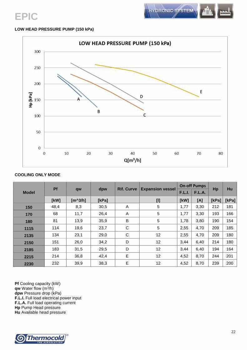
EPIC
22
LOW HEAD PRESSURE PUMP (150 kPa)
COOLING ONLY MODE
Model Pf qw dpw Rif Curve Expansion vessel
On-off Pumps Hp Hu
FLI FLA
[kW] [m^3h] [kPa]
[l] [kW] [A] [kPa] [kPa]
150 484 83 305 A 5 177 330 212 181
170 68 117 264 A 5 177 330 193 166
180 81 139 359 B 5 178 380 190 154
1115 114 196 237 C 5 255 470 209 185
2135 134 231 290 C 12 255 470 209 180
2150 151 260 342 D 12 344 640 214 180
2185 183 315 295 D 12 344 640 194 164
2215 214 368 424 E 12 452 870 244 201
2230 232 399 383 E 12 452 870 239 200
Pf Cooling capacity (kW) qw Water flow (m3h) dpw Pressure drop (kPa) FLI Full load electrical power input FLA Full load operating current Hp Pump Head pressure Hu Available head pressure
EPIC
23
MEDIUM HEAD PRESSURE PUMP (250 kPa)
COOLING ONLY MODE
Model Pf qw dpw Rif Curve Expansion vessel
On-off Pumps Hp Hu
FLI FLA
[kW] [m^3h] [kPa]
[l] [kW] [A] [kPa] [kPa]
150 484 83 305 F 5 255 470 333 303
170 68 117 264 F 5 255 470 313 287
180 81 139 359 F 5 255 470 297 261
1115 114 196 237 G 5 452 870 349 325
2135 134 231 290 G 12 452 870 337 308
2150 151 260 342 G 12 452 870 326 292
2185 183 315 295 H 12 610 1060 313 284
2215 214 368 424 H 12 610 1060 304 261
2230 232 399 383 H 12 610 1060 297 259
Pf Cooling capacity (kW) qw Water flow (m3h) dpw Pressure drop (kPa) FLI Full load electrical power input FLA Full load operating current Hp Pump Head pressure Hu Available head pressure
EPIC
24
HIGH HEAD PRESSURE PUMP (450 kPa)
COOLING ONLY MODE
Model Pf qw dpw Rif Curve Expansion vessel
On-off Pumps Hp Hu
FLI FLA
[kW] [m^3h] [kPa]
[l] [kW] [A] [kPa] [kPa]
150 484 83 305 I 5 425 87 494 463
170 68 117 264 I 5 425 87 473 446
180 81 139 359 I 5 425 87 455 419
1115 114 196 237 L 5 826 136 543 519
2135 134 231 290 L 12 826 136 528 499
2150 151 260 342 L 12 826 136 514 480
2185 183 315 295 L 12 826 136 533 503
2215 214 368 424 M 12 1198 213 520 478
2230 232 399 383 M 12 1198 213 512 474
Pf Cooling capacity (kW) qw Water flow (m3h) dpw Pressure drop (kPa) FLI Full load electrical power input FLA Full load operating current Hp Pump Head pressure Hu Available head pressure
EPIC
25
CONNECTION SCHEME - STANDARD VERSION
Note a water strainer shall always be installed on the inlet water pipe
EPIC
26
HYDRONIC KIT WITH 1 PUMP ndash B1M1A1
Note a water strainer shall always be installed on the inlet water pipe
EPIC
27
HYDRONIC KIT WITH 2 PUMPS - B2M2A2
Note a water strainer shall always be installed on the inlet water pipe
EPIC
28
9 ELECTRICAL DATA
EPIC
NOMINAL VALUES MAXIMUM VALUES (1)
Outdoor air temperature 35degC evaporator water temperature inout 127degC
Model
Compressors (2) Fans TOTAL TOTAL
FLI FLA LRA EP OC FLI FLA SA FLI FLA SA
kW A A kW A kW A A kW A A
150 ZC 130 222 550 30 60 160 282 610 230 410 610
170 ZC 200 298 763 30 60 230 358 823 313 556 823
180 ZC 221 395 1470 45 90 266 485 1730 375 667 1787
1115 ZC 310 516 1700 60 120 370 636 2053 509 905 2109
2135 ZC 393 596 763 60 120 453 716 1181 627 1112 1379
2150 ZC 414 792 1470 90 180 504 972 2216 749 1334 2454
2185 ZC 479 865 1970 120 240 599 1105 2854 855 1526 3146
2215 ZC 599 1009 2150 120 240 719 1249 3113 987 1757 3529
2230 ZC 664 1148 2600 120 240 784 1388 3653 1118 1987 4121
EPIC SL
NOMINAL VALUES
MAXIMUM VALUES (1) Outdoor air temperature 35degC evaporator water temperature inout 127degC
Model
Compressors (2) Fans TOTAL TOTAL
FLI FLA LRA EP OC FLI FLA SA FLI FLA SA
kW A A kW A kW A A kW A A
150 ZC 139 224 550 11 22 150 246 572 230 410 610
170 ZC 210 301 763 11 22 221 323 785 313 556 823
180 ZC 234 398 1470 17 33 251 431 1674 375 667 1787
1115 ZC 328 520 1700 22 44 350 564 1978 509 905 2109
2135 ZC 413 601 763 22 44 435 645 1108 627 1112 1379
2150 ZC 453 797 1470 33 66 486 863 2106 749 1334 2454
2185 ZC 514 871 1970 44 88 558 959 2706 855 1526 3146
2215 ZC 639 1017 2150 44 88 683 1105 2967 987 1757 3529
2230 ZC 709 1157 2600 44 88 753 1245 3508 1118 1987 4121
Electrical data referred to 400V - 3PH+N-50Hz Maximum operating admitted conditions 10 Maximum phase unbalance 3 FLI full load electrical power with max thermal load FLA full load operating current with max thermal load LRA compressor motor locked rotor current (direct starting) SA sum of LRA of the most powerful compressor FLA of other compressor and fans current EP electrical power OC operating current
(1) Values to be considered in the sizing of the power cables and line protection (2) Data referred to the biggest compressor for units with different compressors
EPIC
29
10 ACOUSTIC DATA EPIC
Model
Octave Band (Hz) Lw (db(A)
63 125 250 500 1000 2000 4000 8000
Sound power level (dB)
150 Z 645 605 559 517 493 645 470 360 87
170 Z 695 655 609 567 543 695 520 410 92
180 Z 653 613 567 525 501 653 478 368 88
1115 Z 704 664 618 576 552 704 529 419 93
2135 Z 724 684 638 596 572 724 549 439 95
2150 Z 682 642 596 554 530 682 507 397 91
2185 Z 690 650 604 562 538 690 515 405 92
2215 Z 710 670 624 582 558 710 535 425 94
2230 Z 730 690 644 602 578 730 555 445 96 NOTE The data reported in the table refer to units without the hydraulic version
EPIC SL
Model
Octave Band (Hz) Lw (db(A)
63 125 250 500 1000 2000 4000 8000
Sound power level (dB)
150 Z 595 555 509 467 443 595 420 310 82
170 Z 645 605 559 517 493 645 470 360 87
180 Z 603 563 517 475 451 603 428 318 83
1115 Z 654 614 568 526 502 654 479 369 88
2135 Z 674 634 588 546 522 674 499 389 90
2150 Z 632 592 546 504 480 632 457 347 86
2185 Z 640 600 554 512 488 640 465 355 87
2215 Z 660 620 574 532 508 660 485 375 89
2230 Z 680 640 594 552 528 680 505 395 91 NOTE The data reported in the table refer to units without the hydraulic version
EPIC
30
NOISE CORRECTION FACTORS FOR HYDRAULIC VERSION
For the Hydraulic version please consider the noise output increase due to the addition of the hydraulic group EPIC
Modelli
bassa prevalenza media prevalenza alta prevalenza
1 pompa 2 pompe 1 pompa 2 pompe 1 pompa 2 pompe
[dB(A)] [dB(A)] [dB(A)] [dB(A)] [dB(A)] [dB(A)]
150 ZC 03 03 04 04 08 08
170 ZC 01 01 01 01 03 03
180 ZC 02 02 04 04 07 07
1115 ZC 01 01 02 02 05 05
2135 ZC 01 01 02 02 03 03
2150 ZC 03 03 04 04 08 08
2185 ZC 02 02 04 04 06 06
2215 ZC 02 02 03 03 07 07
2230 ZC 01 01 02 02 04 04
EPIC SL
Modelli
bassa prevalenza media prevalenza alta prevalenza
1 pompa 2 pompe 1 pompa 2 pompe 1 pompa 2 pompe
[dB(A)] [dB(A)] [dB(A)] [dB(A)] [dB(A)] [dB(A)]
150 ZC 08 08 13 13 22 22
170 ZC 03 03 04 04 08 08
180 ZC 07 07 10 10 18 18
1115 ZC 04 04 07 07 15 15
2135 ZC 02 02 05 05 10 10
2150 ZC 08 08 11 11 21 21
2185 ZC 08 08 15 15 21 21
2215 ZC 06 06 08 08 18 18
2230 ZC 04 04 06 06 12 12
Operating conditions Outlet water temperature inout 12degC7degC ndash outdoor air temperature 35degC Testing point Average sound pressure levels calculated according to ISO 9614 at 10 mt distance from unit Measurement conditions Free field on reflecting surface (Q factor Q=2)
bull For units installed in the presence of 2 reflecting surfaces (Q factor Q=4) 3 dB have to be added at values above mentioned bull For units installed in the presence of 3 reflecting surfaces (Q factor Q=8) 6 dB have to be added at values above mentioned bull For units installed at a certain height from the ground the sound energy coming out from the bottom of the unit leads an increase of the noise pressure level of around 3 dB
Sound emission values in octave bands are shown just as an indication and they are not to be considered as a commitment Sound pressure values according to ISO 3744 standards and in observance of EUROVENT certification program are the only ones to be used for every calculation to make a prevision of the sound pressure level at the operating conditions The sound pressure level data are not binding For a more precise value please refer to the sound power level
EPIC
31
11 DIMENSIONAL DRAWINGS AND WEIGHTS
EPIC - BASIC VERSION
150 ZC divide 170 ZC
EPIC
32
150 ZC divide 170 ZC + B1M1A1- B2M2A2
EPIC
33
180 ZC
EPIC
34
180 ZC + B1M1A1- B2M2A2
EPIC
35
1115 ZC divide 2135 ZC
EPIC
36
1115 ZC divide 2135 ZC + B1M1A1- B2M2A2
EPIC
37
2150 ZC
EPIC
38
2150 ZC+ B1M1A1- B2M2A2
EPIC
39
2185 ZC - 2230 ZC
EPIC
40
2185 ZC - 2230 ZC + B1M1A1- B2M2A2
EPIC
41
EPIC - SUPER LOW NOISE VERSION
150 ZC SL divide 170 ZC SL
EPIC
42
150 ZC SL divide 170 ZC SL + B1M1A1- B2M2A2
EPIC
43
180 ZC SL
EPIC
44
180 ZC SL + B1M1A1- B2M2A2
EPIC
45
1115 ZC SL divide 2135 ZC SL
EPIC
46
1115 ZC SL divide 2135 ZC SL + B1M1A1- B2M2A2
EPIC
47
2150 ZC SL
EPIC
48
2150 ZC SL + B1M1A1- B2M2A2
EPIC
49
2185 ZC SL - 2230 ZC SL
EPIC
50
2185 ZC SL - 2230 ZC SL + B1M1A1- B2M2A2
EPIC
51
OPERATION AND SHIPPING WEIGHTS
Operation weights 150 ZC 170 ZC 180 ZC 1115 ZC 2135 ZC 2150 ZC 2185 ZC 2215 ZC 2230 ZC
Basic Version kg 598 657 954 1226 1283 1897 2297 2421 2543
1 Pump - Low head pressure kg 32 32 23 26 26 31 31 74 74
2 Pumps - Low head pressure kg 60 60 43 49 49 58 58 140 140
1 Pump - Medium Head pressure kg 55 55 55 74 74 74 93 93 93
2 Pumps - Medium head pressure kg 104 104 104 140 140 140 176 176 176
1 Pump - High head pressure kg 77 77 77 102 102 102 102 127 127
2 Pumps - High head pressure kg 146 146 146 193 193 193 193 241 241
Increase for version
Super low Noise kg 184 184 238 292 368 476 584 584 584
Shipping weights
150 ZC 170 ZC 180 ZC 1115 ZC 2135 ZC 2150 ZC 2185 ZC 2215 ZC 2230 ZC
Basic Version kg 593 652 943 1218 1270 1884 2280 2404 2522
1 Pump - Low head pressure kg 32 32 23 26 26 31 31 74 74
2 Pumps - Low head pressure kg 60 60 43 49 49 58 58 140 140
1 Pump - Medium Head pressure kg 55 55 55 74 74 74 93 93 93
2 Pumps - Medium head pressure kg 104 104 104 140 140 140 176 176 176
1 Pump - High head pressure kg 77 77 77 102 102 102 102 127 127
2 Pumps - High head pressure kg 146 146 146 193 193 193 193 241 241
Increase for version
Super low Noise kg 184 184 238 292 368 476 584 584 584
Technical data and dimensions are not binding Thermocold reserves the right to make necessary changes without notice
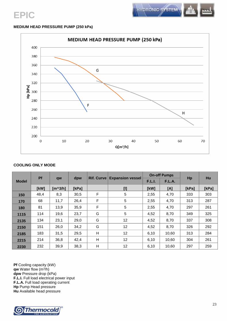
EPIC
29
10 ACOUSTIC DATA EPIC
Model
Octave Band (Hz) Lw (db(A)
63 125 250 500 1000 2000 4000 8000
Sound power level (dB)
150 Z 645 605 559 517 493 645 470 360 87
170 Z 695 655 609 567 543 695 520 410 92
180 Z 653 613 567 525 501 653 478 368 88
1115 Z 704 664 618 576 552 704 529 419 93
2135 Z 724 684 638 596 572 724 549 439 95
2150 Z 682 642 596 554 530 682 507 397 91
2185 Z 690 650 604 562 538 690 515 405 92
2215 Z 710 670 624 582 558 710 535 425 94
2230 Z 730 690 644 602 578 730 555 445 96 NOTE The data reported in the table refer to units without the hydraulic version
EPIC SL
Model
Octave Band (Hz) Lw (db(A)
63 125 250 500 1000 2000 4000 8000
Sound power level (dB)
150 Z 595 555 509 467 443 595 420 310 82
170 Z 645 605 559 517 493 645 470 360 87
180 Z 603 563 517 475 451 603 428 318 83
1115 Z 654 614 568 526 502 654 479 369 88
2135 Z 674 634 588 546 522 674 499 389 90
2150 Z 632 592 546 504 480 632 457 347 86
2185 Z 640 600 554 512 488 640 465 355 87
2215 Z 660 620 574 532 508 660 485 375 89
2230 Z 680 640 594 552 528 680 505 395 91 NOTE The data reported in the table refer to units without the hydraulic version
EPIC
30
NOISE CORRECTION FACTORS FOR HYDRAULIC VERSION
For the Hydraulic version please consider the noise output increase due to the addition of the hydraulic group EPIC
Modelli
bassa prevalenza media prevalenza alta prevalenza
1 pompa 2 pompe 1 pompa 2 pompe 1 pompa 2 pompe
[dB(A)] [dB(A)] [dB(A)] [dB(A)] [dB(A)] [dB(A)]
150 ZC 03 03 04 04 08 08
170 ZC 01 01 01 01 03 03
180 ZC 02 02 04 04 07 07
1115 ZC 01 01 02 02 05 05
2135 ZC 01 01 02 02 03 03
2150 ZC 03 03 04 04 08 08
2185 ZC 02 02 04 04 06 06
2215 ZC 02 02 03 03 07 07
2230 ZC 01 01 02 02 04 04
EPIC SL
Modelli
bassa prevalenza media prevalenza alta prevalenza
1 pompa 2 pompe 1 pompa 2 pompe 1 pompa 2 pompe
[dB(A)] [dB(A)] [dB(A)] [dB(A)] [dB(A)] [dB(A)]
150 ZC 08 08 13 13 22 22
170 ZC 03 03 04 04 08 08
180 ZC 07 07 10 10 18 18
1115 ZC 04 04 07 07 15 15
2135 ZC 02 02 05 05 10 10
2150 ZC 08 08 11 11 21 21
2185 ZC 08 08 15 15 21 21
2215 ZC 06 06 08 08 18 18
2230 ZC 04 04 06 06 12 12
Operating conditions Outlet water temperature inout 12degC7degC ndash outdoor air temperature 35degC Testing point Average sound pressure levels calculated according to ISO 9614 at 10 mt distance from unit Measurement conditions Free field on reflecting surface (Q factor Q=2)
bull For units installed in the presence of 2 reflecting surfaces (Q factor Q=4) 3 dB have to be added at values above mentioned bull For units installed in the presence of 3 reflecting surfaces (Q factor Q=8) 6 dB have to be added at values above mentioned bull For units installed at a certain height from the ground the sound energy coming out from the bottom of the unit leads an increase of the noise pressure level of around 3 dB
Sound emission values in octave bands are shown just as an indication and they are not to be considered as a commitment Sound pressure values according to ISO 3744 standards and in observance of EUROVENT certification program are the only ones to be used for every calculation to make a prevision of the sound pressure level at the operating conditions The sound pressure level data are not binding For a more precise value please refer to the sound power level
EPIC
31
11 DIMENSIONAL DRAWINGS AND WEIGHTS
EPIC - BASIC VERSION
150 ZC divide 170 ZC
EPIC
32
150 ZC divide 170 ZC + B1M1A1- B2M2A2
EPIC
33
180 ZC
EPIC
34
180 ZC + B1M1A1- B2M2A2
EPIC
35
1115 ZC divide 2135 ZC
EPIC
36
1115 ZC divide 2135 ZC + B1M1A1- B2M2A2
EPIC
37
2150 ZC
EPIC
38
2150 ZC+ B1M1A1- B2M2A2
EPIC
39
2185 ZC - 2230 ZC
EPIC
40
2185 ZC - 2230 ZC + B1M1A1- B2M2A2
EPIC
41
EPIC - SUPER LOW NOISE VERSION
150 ZC SL divide 170 ZC SL
EPIC
42
150 ZC SL divide 170 ZC SL + B1M1A1- B2M2A2
EPIC
43
180 ZC SL
EPIC
44
180 ZC SL + B1M1A1- B2M2A2
EPIC
45
1115 ZC SL divide 2135 ZC SL
EPIC
46
1115 ZC SL divide 2135 ZC SL + B1M1A1- B2M2A2
EPIC
47
2150 ZC SL
EPIC
48
2150 ZC SL + B1M1A1- B2M2A2
EPIC
49
2185 ZC SL - 2230 ZC SL
EPIC
50
2185 ZC SL - 2230 ZC SL + B1M1A1- B2M2A2
EPIC
51
OPERATION AND SHIPPING WEIGHTS
Operation weights 150 ZC 170 ZC 180 ZC 1115 ZC 2135 ZC 2150 ZC 2185 ZC 2215 ZC 2230 ZC
Basic Version kg 598 657 954 1226 1283 1897 2297 2421 2543
1 Pump - Low head pressure kg 32 32 23 26 26 31 31 74 74
2 Pumps - Low head pressure kg 60 60 43 49 49 58 58 140 140
1 Pump - Medium Head pressure kg 55 55 55 74 74 74 93 93 93
2 Pumps - Medium head pressure kg 104 104 104 140 140 140 176 176 176
1 Pump - High head pressure kg 77 77 77 102 102 102 102 127 127
2 Pumps - High head pressure kg 146 146 146 193 193 193 193 241 241
Increase for version
Super low Noise kg 184 184 238 292 368 476 584 584 584
Shipping weights
150 ZC 170 ZC 180 ZC 1115 ZC 2135 ZC 2150 ZC 2185 ZC 2215 ZC 2230 ZC
Basic Version kg 593 652 943 1218 1270 1884 2280 2404 2522
1 Pump - Low head pressure kg 32 32 23 26 26 31 31 74 74
2 Pumps - Low head pressure kg 60 60 43 49 49 58 58 140 140
1 Pump - Medium Head pressure kg 55 55 55 74 74 74 93 93 93
2 Pumps - Medium head pressure kg 104 104 104 140 140 140 176 176 176
1 Pump - High head pressure kg 77 77 77 102 102 102 102 127 127
2 Pumps - High head pressure kg 146 146 146 193 193 193 193 241 241
Increase for version
Super low Noise kg 184 184 238 292 368 476 584 584 584
Technical data and dimensions are not binding Thermocold reserves the right to make necessary changes without notice
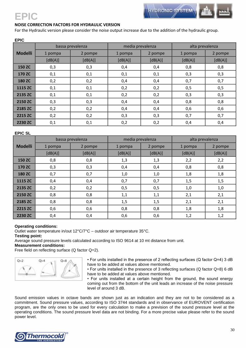
EPIC
33
180 ZC
EPIC
34
180 ZC + B1M1A1- B2M2A2
EPIC
35
1115 ZC divide 2135 ZC
EPIC
36
1115 ZC divide 2135 ZC + B1M1A1- B2M2A2
EPIC
37
2150 ZC
EPIC
38
2150 ZC+ B1M1A1- B2M2A2
EPIC
39
2185 ZC - 2230 ZC
EPIC
40
2185 ZC - 2230 ZC + B1M1A1- B2M2A2
EPIC
41
EPIC - SUPER LOW NOISE VERSION
150 ZC SL divide 170 ZC SL
EPIC
42
150 ZC SL divide 170 ZC SL + B1M1A1- B2M2A2
EPIC
43
180 ZC SL
EPIC
44
180 ZC SL + B1M1A1- B2M2A2
EPIC
45
1115 ZC SL divide 2135 ZC SL
EPIC
46
1115 ZC SL divide 2135 ZC SL + B1M1A1- B2M2A2
EPIC
47
2150 ZC SL
EPIC
48
2150 ZC SL + B1M1A1- B2M2A2
EPIC
49
2185 ZC SL - 2230 ZC SL
EPIC
50
2185 ZC SL - 2230 ZC SL + B1M1A1- B2M2A2
EPIC
51
OPERATION AND SHIPPING WEIGHTS
Operation weights 150 ZC 170 ZC 180 ZC 1115 ZC 2135 ZC 2150 ZC 2185 ZC 2215 ZC 2230 ZC
Basic Version kg 598 657 954 1226 1283 1897 2297 2421 2543
1 Pump - Low head pressure kg 32 32 23 26 26 31 31 74 74
2 Pumps - Low head pressure kg 60 60 43 49 49 58 58 140 140
1 Pump - Medium Head pressure kg 55 55 55 74 74 74 93 93 93
2 Pumps - Medium head pressure kg 104 104 104 140 140 140 176 176 176
1 Pump - High head pressure kg 77 77 77 102 102 102 102 127 127
2 Pumps - High head pressure kg 146 146 146 193 193 193 193 241 241
Increase for version
Super low Noise kg 184 184 238 292 368 476 584 584 584
Shipping weights
150 ZC 170 ZC 180 ZC 1115 ZC 2135 ZC 2150 ZC 2185 ZC 2215 ZC 2230 ZC
Basic Version kg 593 652 943 1218 1270 1884 2280 2404 2522
1 Pump - Low head pressure kg 32 32 23 26 26 31 31 74 74
2 Pumps - Low head pressure kg 60 60 43 49 49 58 58 140 140
1 Pump - Medium Head pressure kg 55 55 55 74 74 74 93 93 93
2 Pumps - Medium head pressure kg 104 104 104 140 140 140 176 176 176
1 Pump - High head pressure kg 77 77 77 102 102 102 102 127 127
2 Pumps - High head pressure kg 146 146 146 193 193 193 193 241 241
Increase for version
Super low Noise kg 184 184 238 292 368 476 584 584 584
Technical data and dimensions are not binding Thermocold reserves the right to make necessary changes without notice
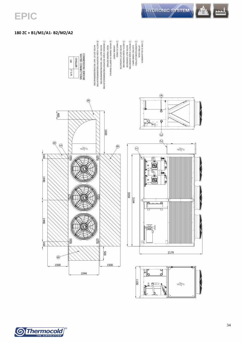
EPIC
37
2150 ZC
EPIC
38
2150 ZC+ B1M1A1- B2M2A2
EPIC
39
2185 ZC - 2230 ZC
EPIC
40
2185 ZC - 2230 ZC + B1M1A1- B2M2A2
EPIC
41
EPIC - SUPER LOW NOISE VERSION
150 ZC SL divide 170 ZC SL
EPIC
42
150 ZC SL divide 170 ZC SL + B1M1A1- B2M2A2
EPIC
43
180 ZC SL
EPIC
44
180 ZC SL + B1M1A1- B2M2A2
EPIC
45
1115 ZC SL divide 2135 ZC SL
EPIC
46
1115 ZC SL divide 2135 ZC SL + B1M1A1- B2M2A2
EPIC
47
2150 ZC SL
EPIC
48
2150 ZC SL + B1M1A1- B2M2A2
EPIC
49
2185 ZC SL - 2230 ZC SL
EPIC
50
2185 ZC SL - 2230 ZC SL + B1M1A1- B2M2A2
EPIC
51
OPERATION AND SHIPPING WEIGHTS
Operation weights 150 ZC 170 ZC 180 ZC 1115 ZC 2135 ZC 2150 ZC 2185 ZC 2215 ZC 2230 ZC
Basic Version kg 598 657 954 1226 1283 1897 2297 2421 2543
1 Pump - Low head pressure kg 32 32 23 26 26 31 31 74 74
2 Pumps - Low head pressure kg 60 60 43 49 49 58 58 140 140
1 Pump - Medium Head pressure kg 55 55 55 74 74 74 93 93 93
2 Pumps - Medium head pressure kg 104 104 104 140 140 140 176 176 176
1 Pump - High head pressure kg 77 77 77 102 102 102 102 127 127
2 Pumps - High head pressure kg 146 146 146 193 193 193 193 241 241
Increase for version
Super low Noise kg 184 184 238 292 368 476 584 584 584
Shipping weights
150 ZC 170 ZC 180 ZC 1115 ZC 2135 ZC 2150 ZC 2185 ZC 2215 ZC 2230 ZC
Basic Version kg 593 652 943 1218 1270 1884 2280 2404 2522
1 Pump - Low head pressure kg 32 32 23 26 26 31 31 74 74
2 Pumps - Low head pressure kg 60 60 43 49 49 58 58 140 140
1 Pump - Medium Head pressure kg 55 55 55 74 74 74 93 93 93
2 Pumps - Medium head pressure kg 104 104 104 140 140 140 176 176 176
1 Pump - High head pressure kg 77 77 77 102 102 102 102 127 127
2 Pumps - High head pressure kg 146 146 146 193 193 193 193 241 241
Increase for version
Super low Noise kg 184 184 238 292 368 476 584 584 584
Technical data and dimensions are not binding Thermocold reserves the right to make necessary changes without notice
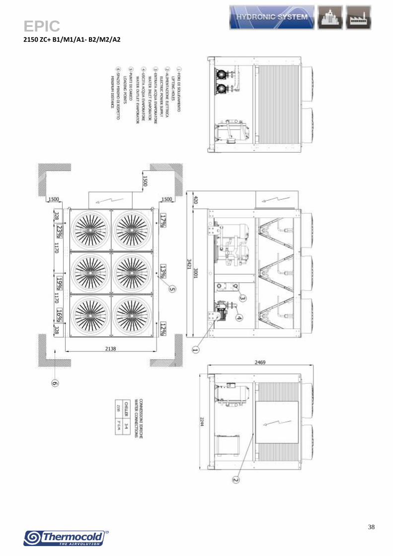
EPIC
44
180 ZC SL + B1M1A1- B2M2A2
EPIC
45
1115 ZC SL divide 2135 ZC SL
EPIC
46
1115 ZC SL divide 2135 ZC SL + B1M1A1- B2M2A2
EPIC
47
2150 ZC SL
EPIC
48
2150 ZC SL + B1M1A1- B2M2A2
EPIC
49
2185 ZC SL - 2230 ZC SL
EPIC
50
2185 ZC SL - 2230 ZC SL + B1M1A1- B2M2A2
EPIC
51
OPERATION AND SHIPPING WEIGHTS
Operation weights 150 ZC 170 ZC 180 ZC 1115 ZC 2135 ZC 2150 ZC 2185 ZC 2215 ZC 2230 ZC
Basic Version kg 598 657 954 1226 1283 1897 2297 2421 2543
1 Pump - Low head pressure kg 32 32 23 26 26 31 31 74 74
2 Pumps - Low head pressure kg 60 60 43 49 49 58 58 140 140
1 Pump - Medium Head pressure kg 55 55 55 74 74 74 93 93 93
2 Pumps - Medium head pressure kg 104 104 104 140 140 140 176 176 176
1 Pump - High head pressure kg 77 77 77 102 102 102 102 127 127
2 Pumps - High head pressure kg 146 146 146 193 193 193 193 241 241
Increase for version
Super low Noise kg 184 184 238 292 368 476 584 584 584
Shipping weights
150 ZC 170 ZC 180 ZC 1115 ZC 2135 ZC 2150 ZC 2185 ZC 2215 ZC 2230 ZC
Basic Version kg 593 652 943 1218 1270 1884 2280 2404 2522
1 Pump - Low head pressure kg 32 32 23 26 26 31 31 74 74
2 Pumps - Low head pressure kg 60 60 43 49 49 58 58 140 140
1 Pump - Medium Head pressure kg 55 55 55 74 74 74 93 93 93
2 Pumps - Medium head pressure kg 104 104 104 140 140 140 176 176 176
1 Pump - High head pressure kg 77 77 77 102 102 102 102 127 127
2 Pumps - High head pressure kg 146 146 146 193 193 193 193 241 241
Increase for version
Super low Noise kg 184 184 238 292 368 476 584 584 584
Technical data and dimensions are not binding Thermocold reserves the right to make necessary changes without notice
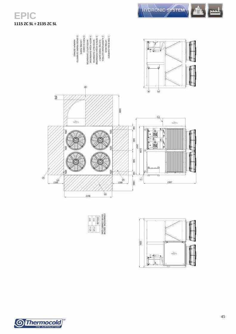
EPIC
46
1115 ZC SL divide 2135 ZC SL + B1M1A1- B2M2A2
EPIC
47
2150 ZC SL
EPIC
48
2150 ZC SL + B1M1A1- B2M2A2
EPIC
49
2185 ZC SL - 2230 ZC SL
EPIC
50
2185 ZC SL - 2230 ZC SL + B1M1A1- B2M2A2
EPIC
51
OPERATION AND SHIPPING WEIGHTS
Operation weights 150 ZC 170 ZC 180 ZC 1115 ZC 2135 ZC 2150 ZC 2185 ZC 2215 ZC 2230 ZC
Basic Version kg 598 657 954 1226 1283 1897 2297 2421 2543
1 Pump - Low head pressure kg 32 32 23 26 26 31 31 74 74
2 Pumps - Low head pressure kg 60 60 43 49 49 58 58 140 140
1 Pump - Medium Head pressure kg 55 55 55 74 74 74 93 93 93
2 Pumps - Medium head pressure kg 104 104 104 140 140 140 176 176 176
1 Pump - High head pressure kg 77 77 77 102 102 102 102 127 127
2 Pumps - High head pressure kg 146 146 146 193 193 193 193 241 241
Increase for version
Super low Noise kg 184 184 238 292 368 476 584 584 584
Shipping weights
150 ZC 170 ZC 180 ZC 1115 ZC 2135 ZC 2150 ZC 2185 ZC 2215 ZC 2230 ZC
Basic Version kg 593 652 943 1218 1270 1884 2280 2404 2522
1 Pump - Low head pressure kg 32 32 23 26 26 31 31 74 74
2 Pumps - Low head pressure kg 60 60 43 49 49 58 58 140 140
1 Pump - Medium Head pressure kg 55 55 55 74 74 74 93 93 93
2 Pumps - Medium head pressure kg 104 104 104 140 140 140 176 176 176
1 Pump - High head pressure kg 77 77 77 102 102 102 102 127 127
2 Pumps - High head pressure kg 146 146 146 193 193 193 193 241 241
Increase for version
Super low Noise kg 184 184 238 292 368 476 584 584 584
Technical data and dimensions are not binding Thermocold reserves the right to make necessary changes without notice
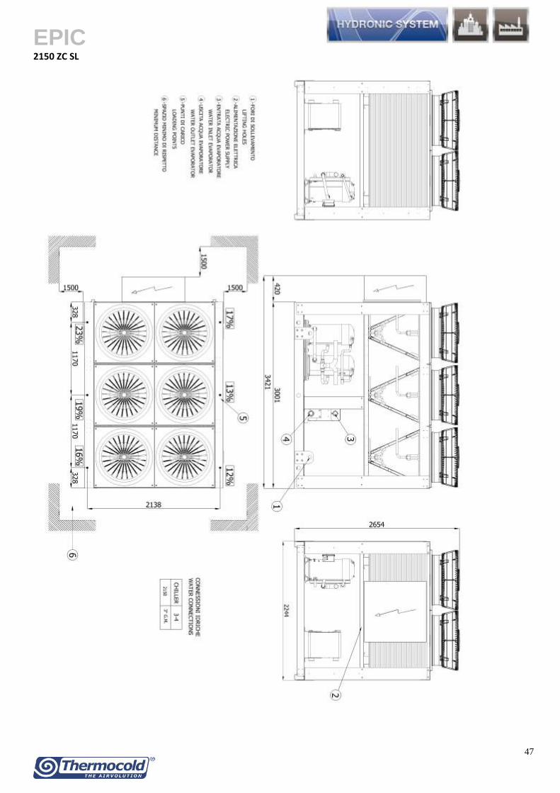
EPIC
51
OPERATION AND SHIPPING WEIGHTS
Operation weights 150 ZC 170 ZC 180 ZC 1115 ZC 2135 ZC 2150 ZC 2185 ZC 2215 ZC 2230 ZC
Basic Version kg 598 657 954 1226 1283 1897 2297 2421 2543
1 Pump - Low head pressure kg 32 32 23 26 26 31 31 74 74
2 Pumps - Low head pressure kg 60 60 43 49 49 58 58 140 140
1 Pump - Medium Head pressure kg 55 55 55 74 74 74 93 93 93
2 Pumps - Medium head pressure kg 104 104 104 140 140 140 176 176 176
1 Pump - High head pressure kg 77 77 77 102 102 102 102 127 127
2 Pumps - High head pressure kg 146 146 146 193 193 193 193 241 241
Increase for version
Super low Noise kg 184 184 238 292 368 476 584 584 584
Shipping weights
150 ZC 170 ZC 180 ZC 1115 ZC 2135 ZC 2150 ZC 2185 ZC 2215 ZC 2230 ZC
Basic Version kg 593 652 943 1218 1270 1884 2280 2404 2522
1 Pump - Low head pressure kg 32 32 23 26 26 31 31 74 74
2 Pumps - Low head pressure kg 60 60 43 49 49 58 58 140 140
1 Pump - Medium Head pressure kg 55 55 55 74 74 74 93 93 93
2 Pumps - Medium head pressure kg 104 104 104 140 140 140 176 176 176
1 Pump - High head pressure kg 77 77 77 102 102 102 102 127 127
2 Pumps - High head pressure kg 146 146 146 193 193 193 193 241 241
Increase for version
Super low Noise kg 184 184 238 292 368 476 584 584 584
Technical data and dimensions are not binding Thermocold reserves the right to make necessary changes without notice