Embed Size (px)
Citation preview
Ii Future Reference
_AIRS
MODEL O.113.236150
Serial
Number
Model and serial number may befound attached to the rightside ofarm housing.
You should record both modeland serial number in a safe placefor future use.
i ii llllINNI ' II ................
FOR YOURSAFETY:
Read ALLiNSTRUCTIONS
carefully
16 INCH RIABLESPEED SCROLL SAW
, assembly• operating
repair parts
........... , ......... J _ ........................
Sold by SEARS, ROEBUCK AND CO., Chicago, IL. 60684 U.S.A.Part No_SP5641

SCROLL SAW
Scroll Saw fails due to a defect in material or work-
RETURNING:THE CRAFTSMAN SCROLL SAW TO THEE CENTER/DEPARTMENT IN THE UNITED
':IS USED IN THE UNITED STATES.
'ights which vary from state to state.IL: 60195
Safer
Safety is a combination of common sense, staying alertand knowing how your scroll saw works. Read this man,ual to understand this saw.
_Safety Signal Words
DANGER: means if the safety information is not followedsomeone will be seriously;injured or killed.
WARNING: means if the-safety information isnot fol-lowed someone could be seriously injured or killed.
CAUTION: means if the safety information is not followedsomeone might be injured.
Before Using The Saw
the following steps are: corn pleted.
Assembly and alignment (See pages 7-12)Learn the:;:::useand function of the speed control ON-
OFF knob, bevel: lock knob, blade holders, blade sup,port, hold down, tension knob, and blade guard. (Seepages14:16)
• Review and Understand at! safety instructions andoperating procedures in this manual.
• Review of the maintenance:meth0ds for this saWi:(Seepage 20)
" Read the WARNING tabeJ!Seiow,found_n t_eba_eofthe saw.
, WARNING
When Installing or Moving The Saw
To Avoid Injury from Unexpected Saw Movement:
• Turn saw off and unplug cord before moving the saw.• Put the saw on a firm level surface where there is
plenty of room for handling and properly supporting theworkpiece.
• Support the saw so the table is level and the saw doesnot rock.
= Bolt the saw to the work surface if it tends to slip, walk,or slide during operations like cutting long heavyboards, or when using an auxiliary table.
o NEVER STAND ON TOOL. Serious injury could occurif the tool tips or you accidentally hit the cuttingtool. Donot store anything above or near the tool where any-one might stand on the too! to reach them.
To Avoid Injury or Death from Electrical Shock:
° GROUND THE SAW, This saw has an approved 3 con-ductor cord and a 3-prong grounding type plug. Useonly:3-wire, grounded outlets rated 120 volts, 15amperes (amps), The green conductor in the cord isthe grounding wire. :To avoid electrocution, NEVERconnect the green wire to a live terminal.
• Make sure your fingers do not touch the plug's metalprongs when plugging or unpluggingthe saw.
Before Each Use:
InsPect your saw,
DISCONNECT THE SAW. To avoid injury from accidentalstarting, unplug the saw, turn the switch off and lock outthe switch before changing the setup, removing covers,guards or blade.
CHECK DAMAGED PARTS. Check for:- Alignment of moving parts.
• Binding of moving parts.
• Broken parts.
• Stable mounting.
° Any other conditions that may affect the way the sawworks.
If any part is missing, bent or broken in any way, or an_electrical parts don't work properly, turn the saw off ariaunplug the saw. REPLACE damaged, missing or failed
dry indoor _place, prote=_edfrom rain:i Keep work area parts before using the saw again.well lighted.
Maintain Tools with Care, Keep the saw cleanfor best and safest performance. Follow instruc-
ns for lubricating.move adjusting keys and wrenches from tool before
turning it on.
To avoid injury from jams, slips or thrown pieces:
• Choose the right size and style blade for the materialand the type of cutting you plan to do.
• Use Only Recommended Accessories.
(See page 21). Consult this owners manual for recom-mended accessories. Follow the instructions that comewith the accessories. The use of improper accesso-ries may cause risk of injury to person.
• Make sure the blade teeth point downward, towardthe table.
• Make sure the blade tension is properly adjusted.
, Make sure the bevel lock knob is tight and no partshave excessive play.
• To avoid accidental blade contact, minimize bladebreakage and provide maximum blade support, alwaysadjust the work and blade guard to just clear the work-piece.
• Keep Work Area Clean. Cluttered areas and benchesinvite accidents. Floor must not be slippery.
To avoid burns or other fire damage, never use the saw._nearflammable liquids, vapors or gases.
!tan Ahead to Protect Your Eyes, Hands,Face and Ears
, Know Your Saw. Read and understand the ownersmanual and labels affixed to the tool. Learn it's appli-cation and limitations as well as the specific potentialhazards peculiar to this tool.
° To avoid injury from accidental contact with movingparts, don't do layout, assembly, or setup work on thesaw whi;_eany parts are moving.
• Avoid Accidental Starting. Make sure switch is"OFF" before plugging saw into a power outlet.
Plan Your Work.
• Use The Right Tool. Don't force tool or attachment todo a job it was not designed to do.
• Use this scroll saw to cut only wood, wood-like prod-ucts, plastics and non-ferrous metals.
CAUTION: This saw is NOT designed for cutting fer-rous metals like iron or steel. When cutting non-fer-rous metals (brass, copper and aluminum, etc.),metal shavings can react with wood dust and start afire. To avoid this:
°Remove all traces of wood dust from on and
round the saw.Remove all metal shavings from on or around the
I saw before sawing woo d again,
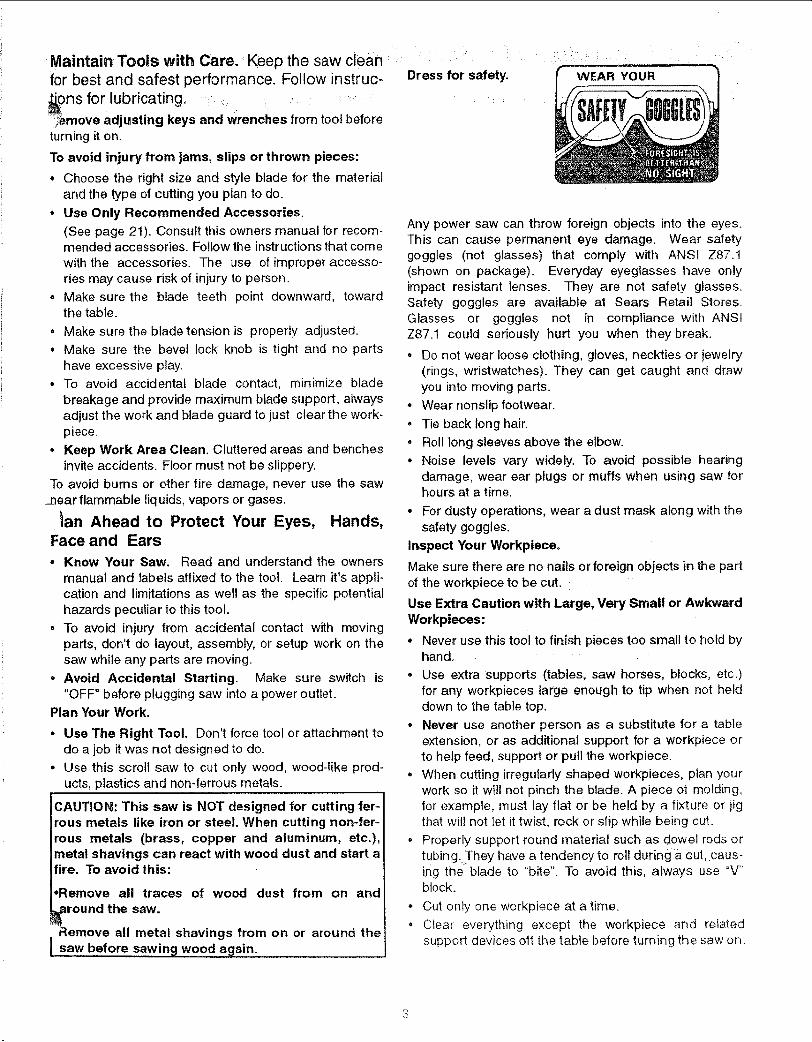
Dress for safety. WEAR YOUR
Any power saw can throw foreign objects into the eyes.This can cause permanent eye damage. Wear saletygoggles (not glasses) that comply with ANS! Z87.1(shown on package). Everyday eyeglasses have onlyimpact resistant lenses. They are not safety glasses.Safety goggles are available at Sears Retail Stores.Glasses or goggles not in compliance with ANSIZ87.1 could seriously hurt you when they break.
• Do not wear loose clothing, gloves, neckties or jewelry(rings, wristwatches). They can get caught and drawyou into moving parts.
° Wear nonslip footwear.
• Tie back long hair.• Roll long sleeves above the elbow.
° Noise levels vary widely. To avoid possible hearingdamage, wear ear plugs or muffs when using saw forhours at a time.
° For dusty operations, wear a dust mask along with thesafety goggles.
Inspect Your Workpieceo
Make sure there are no nails or foreign objects in the partof the workpiece to be cut.
Use Extra Caution with Large, Very Small or AwkwardWorkpieces:
• Never use this too! to finish pieces too small to hold byhand.
° Use extra supports (tables, saw horses, blocks, etc.)for any workpieces large enough to tip when not helddown to the table top.
° Never use another person as a substitute for a tableextension, or as additional support for a workpiece orto help feed, support or pull the workpiece.
• When cutting irregularly shaped workpieces, plan yourwork so it will not pinch the blade. A piece of molding,for example, must lay flat or be held by a fixture or jigthat will not let it twist, rock or slip while being cu_.
° Properly support round material such as dowel rods or
tubingJhey have a tendency to roll during a cut, caus-ing the blade to "bite". To avoid this, always use "V"block.
• Cut on!y one workpiece at a time.• Clear everything except the workpiece and related
support devices of_ the table before turning the saw on.
•Donot handhc
sudden slip €_iithe blade.
Y_U Wilti Holld the Workpiece Before Leaving the Saw:in'i_h,:,_: ' ° Waitforall rnovingparts to stop.
:l:pieces s_:ismall thatyour:fingers will ...... Make Workshop Child-proof. Unplug the saw. Locki_gula_.:iOse jigs or fixtures to :hold the shop or ONIOFF knob. Store the key away fromipyo_r_hands away from the blade: children and others not qualified to use the toot.
;_e_ati_ns and hand positions where ad cause fingers or hand to move into
o_:Don,t Overreach. Keep good footing and balance.
° Keep your face and body to one side of the blade, outoftine with a possible thrown piece if the blade shouldbreak.
Whenever Saw Is Running:WARNING: Don't let familiarity (gained from fre-quent use of your scroll saw) cause a carelessmistake. A careless fraction of a second isenough to cause a Severe injury,
• Before starting your cut, watCh the saw while it runs. Ifit makes an unfamiliar noise or Vibrates excessively,stop' immediately Turn the saw off:Unplug the:saw:_Donot restart until findingand correctin gthe problem,
• Keep Children Away. Keep;all:visitors a:saf e distance
i from :the saW.:Make,sure bystanders are:clear of thesaw and wo_tSieCei:i :
• Don-t; ForCe::T_l::it better and safer atits designed rate. Feed the workpiece intothe sawblade only fast enough to let ,it cut without:boggingdown or binding.=
Before Freeing Any Jammed Materia !,
• Turn switch "OFF"
• Unplug the saw.
• : Wait for all moving parts to:stop.
When backing up the workpiece, the blade may bindin the kerf (cut),This iiS usually caused by Sawdustclogging up the kerr. If this happens:
• Turn switch "OFF".
• Unplug the saw.
° Wait for all moving padsto stop.
- With a flat blade screwdriver, turn motor shaft by hand,by inserting into the slotted end of motor shaft locatedat the center of the motor housing. Do this while back-ing up the workpiece:
Before removing loose pieces from the table, turnsawoff and wait foraU moving parts to stop:
Motors, Specifications and Electricat Requirements , ....This machine is equipped:witha var able speed motor_ It_ired for operation on 120V, 60Hz, alternating current.
CAUTION: A direct current motor is used in thisjsaw. Changes to the internal wiring will create a fire I
hazard and may also create a shock hazard. ]
For replacement motor and control board, refer to partslist in this manual.
Connecting To Power Supply Outlet
If power cord is worn or cut, or damaged in any way,have it replaced immediately.
WARNING: if not properly grounded, this power toolcan cause an electrical shock, particularly whenused in damp locations close to plumbing. If anelectrical shock occurs there is potential of a sec-ondary hazard, such as your hands contacting thesaw blade.
If you are not sure that your outlet, as pictured below, isproperly grounded, have it checked by a qualified electri-cian.
WARNING: Do not permit fingers to touch the termi-nals of plug when installing or removing the plug toor from the outlet.
Plug power cord into a 120V properly grounded type out-let.
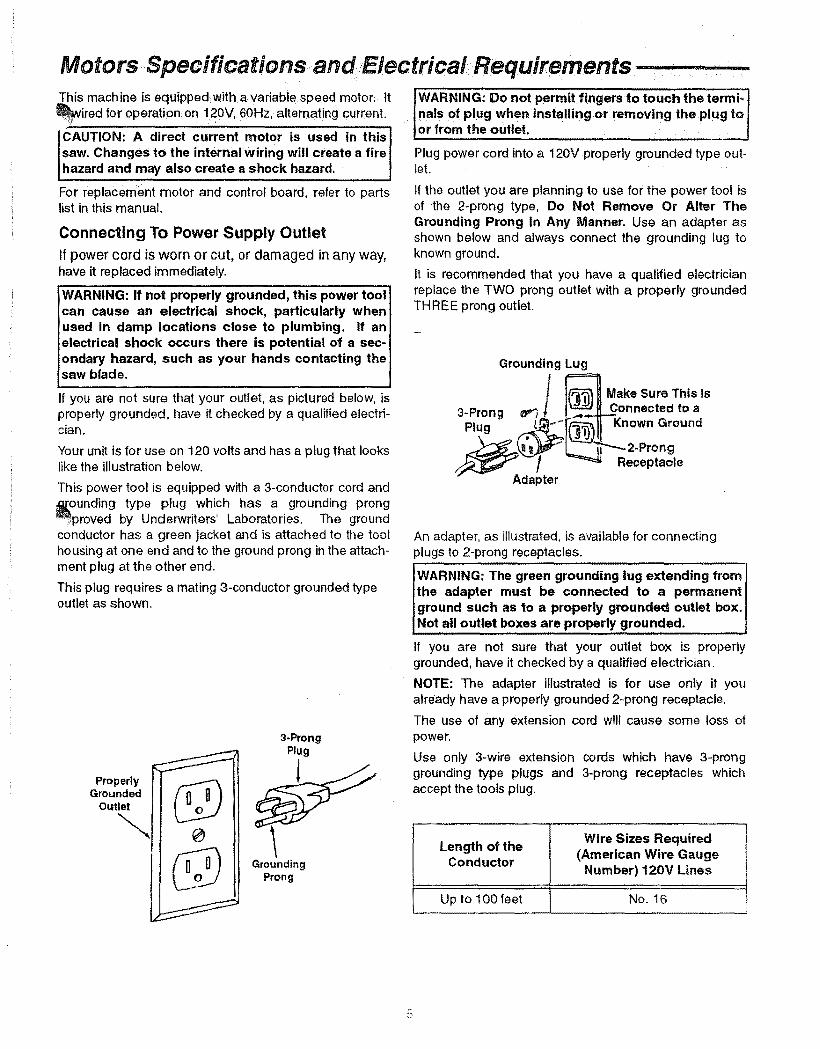
If the outlet you are planning to use for the power tool isof the 2-prong type, Do Not Remove Or Alter TheGrounding Prong In Any Manner. Use an adapter asshown below and always connect the grounding tug toknown ground.
It is recommended that you have a qualified electricianreplace the TWO prong outlet with a properly groundedTHREE prong outlet.
Grounding Lug
Make Sure This Is
3-Prong _ Connected to aPlug Known Ground
Your unit is for use on 120 volts and has a plug that lookslike the illustration below.
This power tool is equipped with a 3-conductor cord and_[ounding type plug which has a grounding prong_v._proved by Underwriters' Laboratories. The groundconductor has a green jacket and is attached to the toolhousing at one end and to the ground prong in the attach-ment plug at the other end.
This plug requires a mating 3-conductor grounded typeoutlet as shown.
ProperlyGrounded
Outlet
--.., 0
3-ProngPlug
UGrounding
Prong
Adapter
,gReceptacle
An adapter, as illustrated, is available for connectingplugs to 2-prong receptacles.
I WARNING: green grounding lug extending from
The
the adapter must be connected to a permanentground such as to a properly grounded outlet box.Not all outlet boxes are properly grounded.
If you are not sure that your outlet box is properlygrounded, have it checked by a qualified electrician.
NOTE: The adapter illustrated is for use only if youalready have a properly grounded 2-prong receptacle.
The use of any extension cord will cause some loss ofpower.
Use only 3-wire extension cords which have 3-pronggrounding type plugs and 3-prong receptacles whichaccept the tools plug.
Wire Sizes RequiredLength of the (American Wire Gauge
ConductorNumber) 120V Lines
Up to 100 feet No. 16
Ke_:::; th_!s|ot::c_t!iby :th_ibiade:_ = ::!: :::::=:: 5,:Blade Tooth Set:-::the distance:that the edge of th_work' _:_wh:iCh is: : : saWblade tOothisb_ni (orset Outward fromthes,det2.:LeadlngEdge:_!_= ...... g ............. p .................: : _. ....... ........... : )
:/::.puShed: into theibiade:first: : : ::::the:b!ade_::: ::::::::::_:!_,: ::: ......... 0fthework 6 Trailing Edge;:; the work iece ed e last cut b the3_:Sawbtm:fe Path:,- the area : : p ..... y ..... ..... ......... .......P g . y
toward the sawbiade edge:;::: :i:Sawblade. : ,:4-1:Bevel' -:the blllty'.....to slant thetable to make ........angie cuts. 7 , Wor:kp:iece :- the item :onWhichthe cutting operation is
:: angle cuttir_g operati0nl through the face:of the being performed.board.
-::ContentsW_rranty Information.... ........................... ...................... 2
ety Instructions for Scroll Saws :...... i.. ..:i ::..: .. 2Motor Specs and Electrical Requirements .................. :. 5Glossary of Terms for Woodworking ... ................. ..... :..:6Unpacking and Checking Contents ............................... 6Assembly and Alignment ............................................... 7
Setting Table for Horizontal or Bevel Cutting ..........8Aligning the Bevel Indicator .................................... 8
Removing and Installing Blades .... ................... ..,._..:.._10Adjusting Work Hold-Down Foot. ...................... .,.L.... 12Dust Blower .................................................................. 12Blade Guard: ...................................... :......................... 12
i ....
Mounting the Scroll Saw ............................................. 13Getting to Know Your Scroll Saw ................................. 14
Speed Control/On-OFF Knob ............................... 15Choice of Blade and Speed .................................. 16
Operation .................................................................... 17Making Interior Cuts ............................................. 19
Maintenance ................................................................ 20Wiring Diagram ........................................................... 2IRecommended Accessories ....................................... 21Troubleshooting ........................................................... 21Repair Parts ................................................................ 22Service Information ....................................... Back Cover
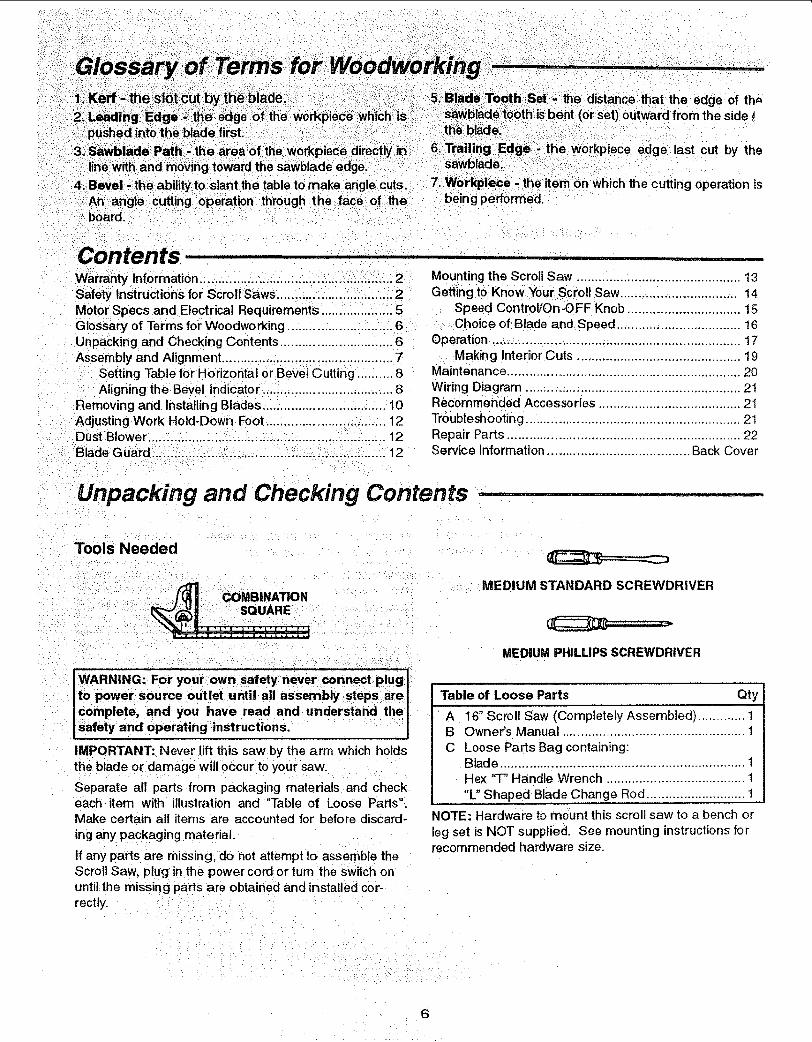
Unpacking and Checking Contents ........
Tools Needed
::j_ COMBINATION
WARNING: For your own safety never connect plugto power sou rce outlet until all assembly iStepsarecomplete, and you have read and understand thesafety and operating instructions.
IMPORTANT: Never lift this saw by the arm which hotdsthe blade or damage will occur to your saw.
Separate all parts from packaging materials and checkeach item with illustration and "Table of Loose Parts".Make certain all items are accounted for before discard-
ing any packaging material.
If any parts are missing, do not attempt to assemble theScroll Saw, plug in the power cordor turn the switch onuntil the missing parts are obtained and installed cor-rectly.
MEDIUM STANDARD SCREWDRIVER
MEDIUM PHILLIPS SCREWDRIVER
Table of Loose Parts Qty
A 16" Scroll Saw (Completely Assembled) ............. 1B Owner's Manual .................................................. 1C Loose Parts Bag containing:
Blade ................................................................... 1Hex "T" Handle Wrench ...................................... 1"L" Shaped Blade Change Rod ........................... 1
NOTE: Hardware to mount this scroll saw to a bench orleg set is NOT supplied. See mounting instructionsforrecommended hardware size.
Lift
C
Do not lift saw by this arm
Here
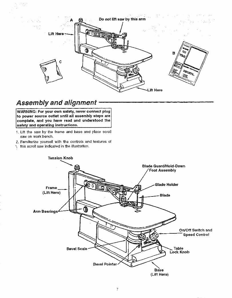
Assembly and alignment ...............................................WARNING: For your own safety, never connect plugto power source outlet until all assembly steps arecomplete, and you have read and understood thesafety and operating instructions.
1. Lift the saw by the frame and base and place scroltsaw on work bench.
2. Familiarize yourself with the controls and features of'_ this scroll saw indicated in the illustration.
Tension Knob
Blade Guard/Hold-DownAssembly
Frame(Lift Here)
Arm Bearings _
Holder
de
On/Off Switch andSpeed Control
Bevel TableLock Knob
BevelBase
(Lift Here)
ng
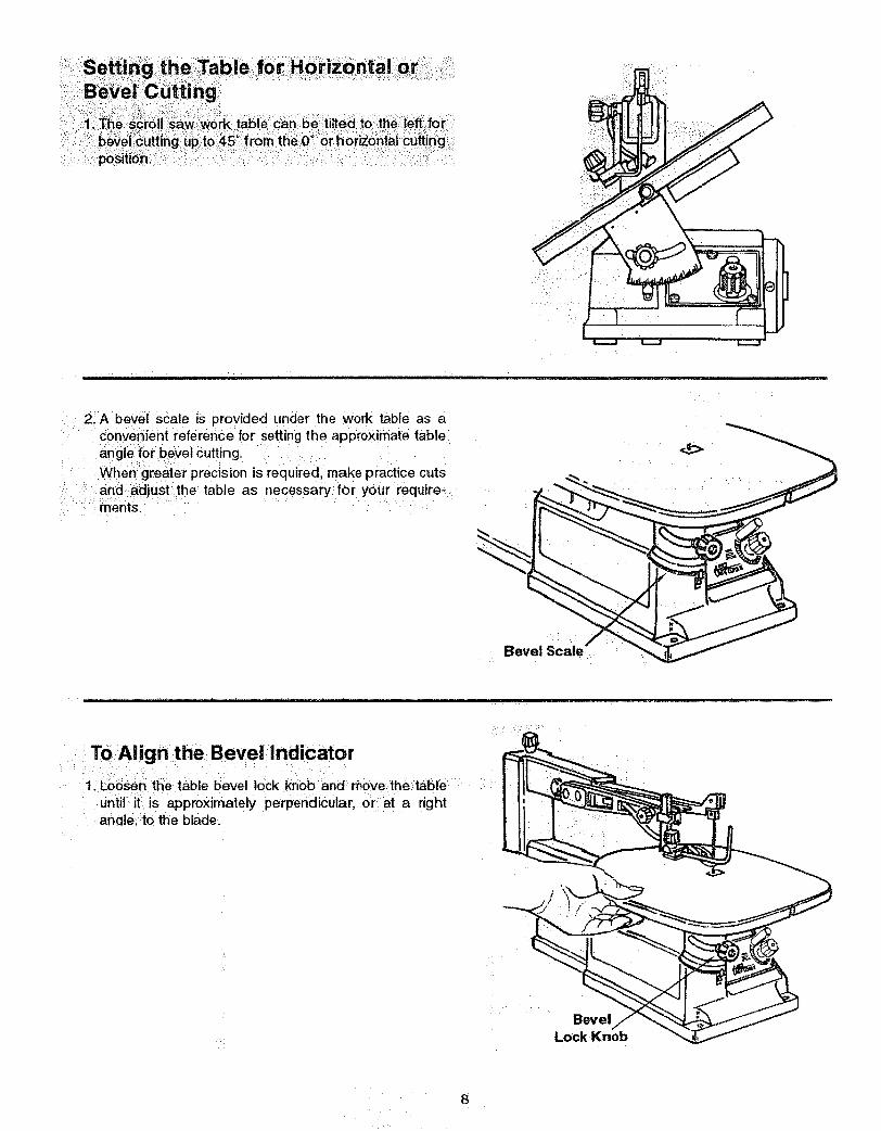
2. A bevel scale is provided under the work table as aconvenient reference for setting the approximate tableangle for bevel cutting.
When greater precision is requiredl make practice cutsand :adjust the table as necessary:for your require-
: .... ments.
• J
ToAlign the Bevel indiCator
11Lo_n_ttle table bevei lock knob an_ move,the:table ::
until iti is approximately perpehdicutar;_ Or:iat a rightanale:to the blade,:
L¸ BevelLock Knob
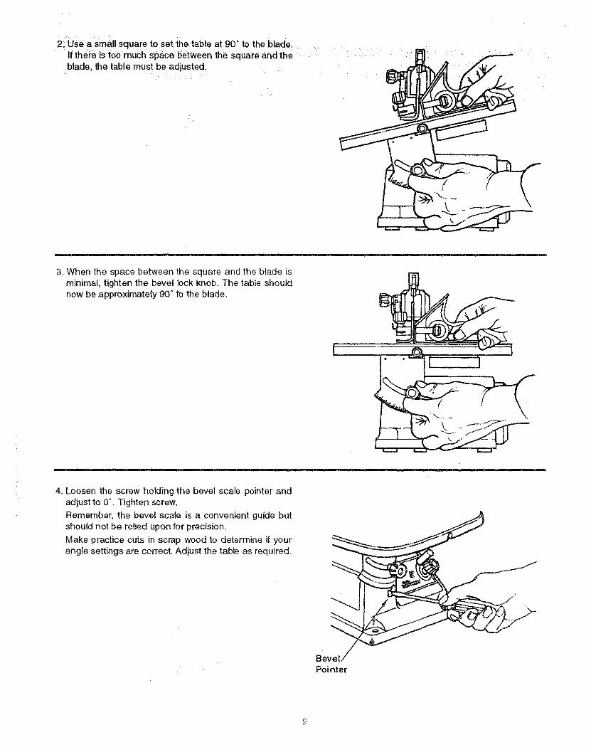
2_Use a small square to set the table at 90" to the blade.If there is too much space between the square and theblade, the table must be adjusted.
3. When the space between the square and the blade isminimal, tighten the bevel lock knob, The table shouldnow be approximately 90 ° to the blade,
.......
4. Loosen the screw holding the bevel scale pointer andadjust to 0°. Tighten screw.
Remember, the bevel scale is a convenient guide butshould not be relied upon for precision,
Make practice cuts in scrap wood to determine if yourangle settings are correct. Adjust the table as required.
Bevel
Pointer

Removing Pin End Blades
1: UnP!ug=powercord from outlet and Checkthat switch isofL
2. Loosen tension on blade by turning tension knob coun-terclockwise _ about three full turns.
3. Remove blade from the lower blade holder by pushingdown on the upper arm, releasing the blade/pin fromthe lower blade holder. Remove blade from the upperblade holder by slightly lifting up on the blade and pull-ing forward.
Knob
Blade Change Rod
UpperBlade Holder
"T" Wrench
II
J
NOTE: Teeth pointing downward.
NOTE: Thesaw comes from the factory already setupfor pin end blades.1. Pin End Blade Set Up: Insert the blade change rod
through the holeabove the upper blade holder. Usethe "T' handle wrench to loosen the h ex socket screwand clamp from the upper blade holder. Install theClamp so that the boss goes into the recess in theblade holder: The "V" notcheSmust line up.
2. Tighten_he hex socket screw:3_Repeat this prOcb_e_i:_n t_heIowgi_blade holder.:4'iCheck that the tension knob is loose:
5!instal{ the blade throughlthe insert opening with theteeth pointing down, Engage the pin into the "V" notchof :thelower blade:holder:
6. Pullup on the blade and engage the upper pin in thenotch of the upper blade holder.
7. Carefully tighten the blade tension by turning the ten-sion knob clockwise _ until you feel the slack inthe blade is removed.
8. Check to see that the pins are properly located in theslots. Turn the tension knob an additional two full turnsclockwise. This amount of blade tension should dowell for most cutting operations and blades. The num-ber of turns Will be approximately two full turns. Thiswill vary depending on blade :thiCkness and blade type.
9. Make sure the blade is properly installed. Before apply-Ing power, rotate the motor shaft by hand using ascrewdriver in the motor shaft slot as shown,
IWARNING: To avoid from thrown
injury objects,
remove the blade change rod and all tools from thesaw.
Lower
Blade Holder
ecess
%Blade Clamp Upper Blade Holder
Boss _)
"V"Notches Recess
Blade Clamp Lower Blade Holder
10
• • i _
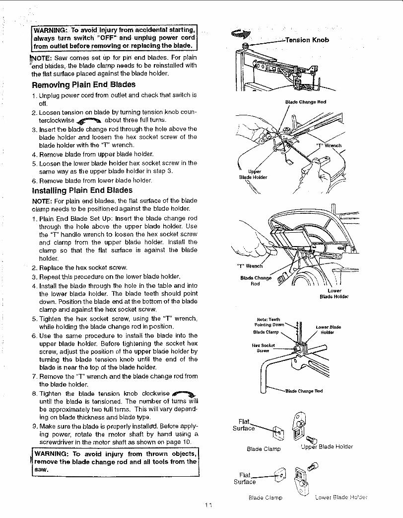
I WARNING: To avoid,injury from accidental starting,lalways turn switch' OFF"and unplug power cordlfrom outlet before removing or,replacing the blade.
OTE: Saw comes set up, for pin end blades. For plain=end blades, the blade clamp needs to be reinstalled withthe flat surface placed against the blade holder.
Removing Plain End Blades
1. Unplug power cord from outlet and check that switch isoff.
2. Loosen tension on blade by turning tension knob coun-
terclockwise _ about three full turns.3. Insert the blade change rod through the hole above the
blade holder and loosen the hex socket screw of theblade holder with the "T" wrench.
4. Remove blade from upper blade holder.5. Loosen the lower blade holder hex socket screw in the
same way as the upper blade ho]der in step 3.6. Remove blade from lower blade holder.
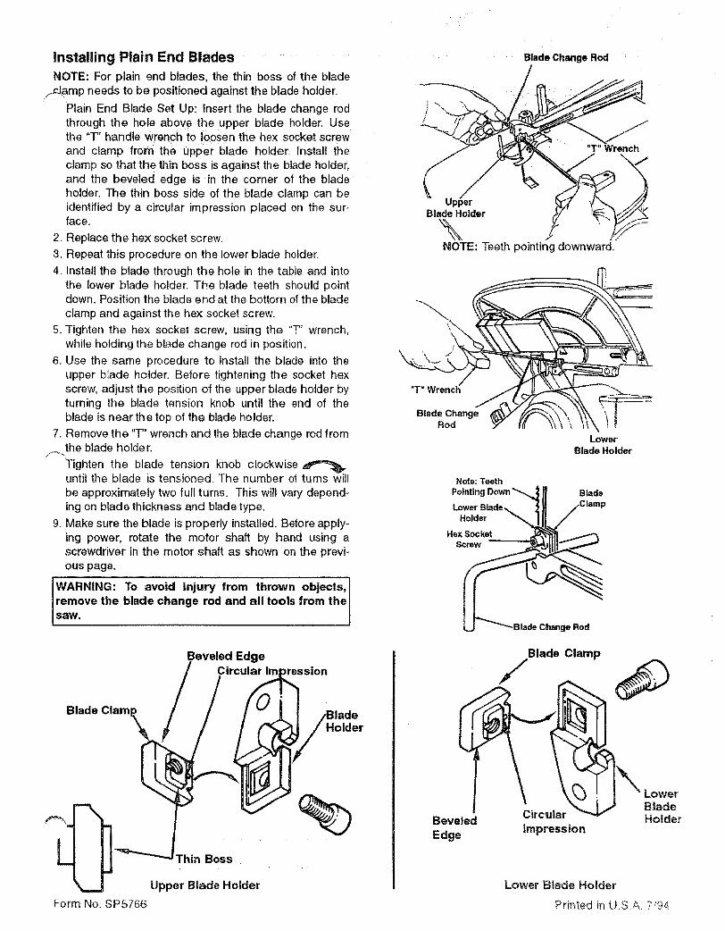
Installing Plain End Blades
:NOTE: For plain end blades, the flat surface of the bladectamp needs to be positioned against the blade holder.
1. Plain End Blade Set Up: insert the blade change rodthrough the hole above the upper blade holder. Usethe "T" handle wrench to loosen the hex socket screwand clamp from the upper blade holder. Install theclamp so that the flat surface is against the bladeholder.
.... 2. Replace the he>(socket screw.
3. Repeat this procedure on the lower blade holder.4. Install the blade through the hole in the table and into
the lower blade holder. The blade teeth should pointdown. Position the blade end at the bottom of the bladeclamp and against the hex socket screw.
5. Tighten the hex socket screw, using the "T" wrench,while holding the blade change rod in position.
6. Use the same procedure to install the blade into theupper blade holder. Before tightening the socket hexscrew, adjust the position of the upper blade holder byturning the blade tension knob until the end of theblade is near the top of the blade holder.
7. Remove the "T" wrench and the blade change rod fromthe blade holder.
8. Tighten the blade tension knob clockwiseuntil the blade is tensioned. The number of turns willbe approximately two full turns. This will vary depend-ing on blade thickness and blade type.
9. Make sure the blade is properly installed. Before apply-ing power, rotate the motor shaft by hand using ascrewdriver in the motor shaft as shown on page 10.
JWARNING: To avoid injury from thrown objects,!PIremove the blade change rod and all tools from thel saw. I
11
ion Knob
Blade Change Rod
"T" Wrencl_
Blade ChangeRod
lLower
Blade Holder
Lower BirdieHolder
BRod
Blade Clamp
Surface '-_
Blade C!am£
Upper Blade Holder
Lower B!_de _.o!de_
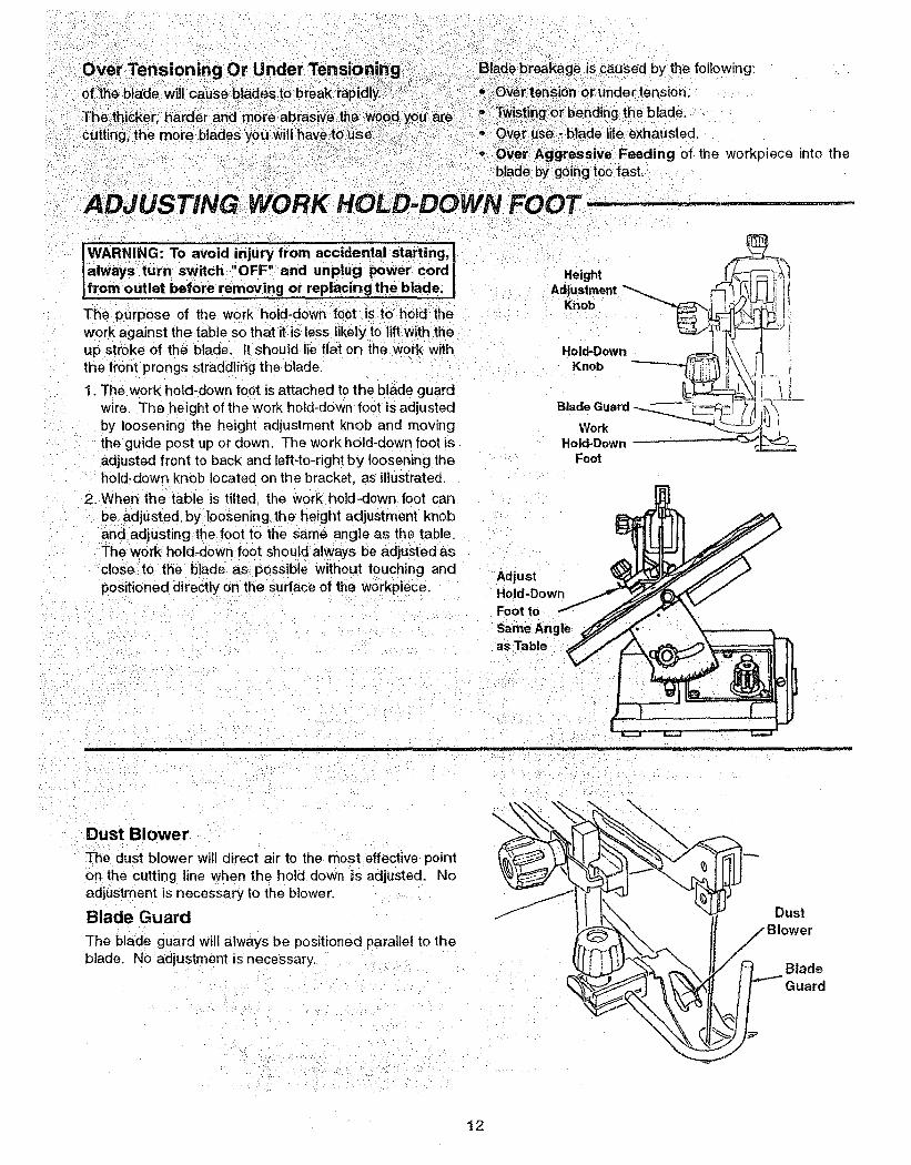
wARNING: To avoid i'njury from accidental starting,alwwsturn switch:"OFP and unplug power cord ;,fromoutlet before removing or replacing the blade;
The purpose of the work hold_down foot is to hold thework against the table so that it :is less likely io liftwith:theup stroke of the blade, tt should lie flat on the work withthe front prongs straddling the blade.
1. The work hold-down foot is attached to the blade guardwire. The height of the work hold-down foot is adjustedby loosening the height adjustment knob and movingthe guide post up or down. The work hold-down foot isadjusted front to back and left-to-rightby loosening thehold-down knob located on the bracket, as illustrated
2. When the table is tilted, the work hold-down foot canbe adjusted by loosening the height adjustment knoband adiustingthe foot to the same angle as the table.The work hold-downfoot should always be adjusted asclose to the blade as: possible without touching andpositioned directly on the surface of the workpiece.
breakage _iScaused by:the following:';_tensi_n orunde_tension:
;i:_iuse::!i_biade iiife :exiiausted;
;rAggressive_ Feeding of the workpiece into the:te bygoing too:fast,
OOT
Height
AdjustmentKnobHold-Down
Knob _
Hold-DownFoot
AdjustHold-Down
Foot to
Same Angleas Table
Dust Blower
The dust blower will direct air to the most effective pointon the cutting line when the hold down is adjusted. Noadjustment is necessary to the blower.
Blade Guard
The blade guard will always be positioned parallel to the
blade. No adjustment is necessary,
i__ iil -- B/oUSter
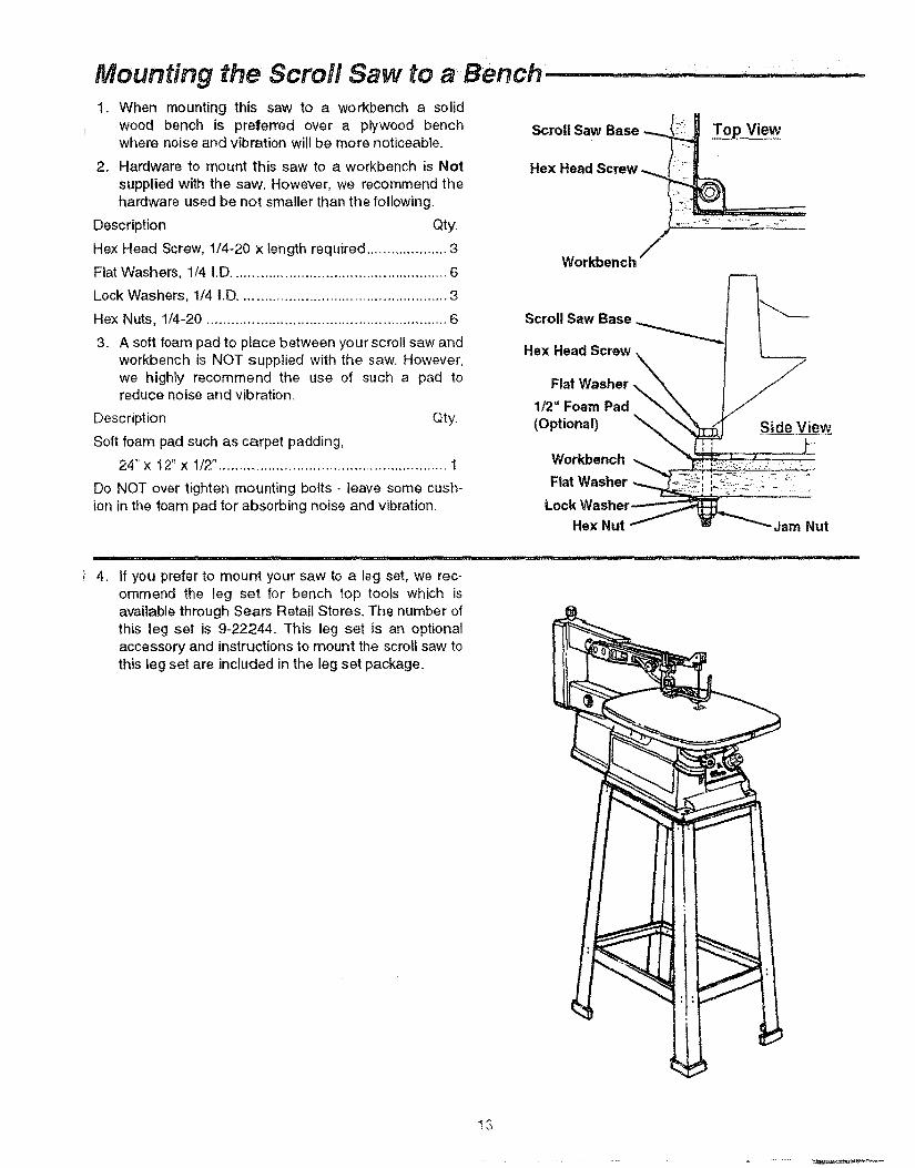
ii ,I,L±I_lji, , _i i,li, ilrli ,11 ,Mounting the Scroll Saw to a Bench 1. When mounting this saw to a workbench a solid
wood bench is preferred over a plywood benchwhere noise and vibration will be more noticeable.
2, Hardware to mount this saw to a workbench is Notsupplied with the saw. However, we recommend thehardware used be not smaller than the following.
Description Qty.
Hex Head Screw, 1/4-20 x length required .................... 3
Flat Washers, 1/4 I.D ..................................................... 6
Lock Washers, 1/4 i.D ................................................... 3
Hex Nuts, 1/4-20 ........................................................... 6
3. A soft foam pad to place between your scroll saw andworkbench is NOT supplied with the saw. However,we highly recommend the use of such a pad toreduce noise and vibration.
Description Qty.
Soft foam pad such as carpet padding,
24"x 12" x 1/2". ....................................................... I
Do NOT over tighten mounting bolts - leave some cush-ion in the foam pad for absorbing noise and vibration.
Scroll Saw Base
Hex Head Screw
] _% •
Top View
Workbench /
Scroll Saw Base ._
Hex Head Screw X
Flat Washer -_"\1/2" Foam Pad. _'N_
(Optional) '__ Side View
Workbench
Ftat Washer
Lock Washer___=Hex Nut Jam Nut
, If you prefer to mount your saw to a leg set, we rec-ommend the leg set for bench top tools which isavailable through Sears Retail Stores. The number ofthis leg set is 9-22244. This leg set is an optionalaccessory and instructions to mount the scroll saw tothis leg set are included in the leg set package.
13
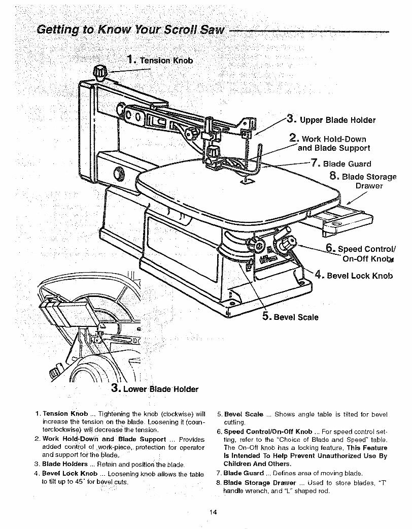
Upper Blade Holder
2. Work Hogd-Down
Blade Support
7. BladeGuard
8. Blade StorageDrawer
Speed Control/On-Off Knol_
4. Bevel Lock Knob
3, Lower Blade Holder
5. Bevel Scale
1. Tension Knob ... Tightening the knob (clockwise) willincrease the tension on the blade. Loosening it (coun-terclockwise) will deCreaSe the tension.
2. Work Hold-Down and Blade Support ... Providesadded control of work-p!ece, protection for operatorand support for the blade_
3. Blade Holders ... Retain and position the blade,
4. Bevel Lock Knob ... Loosening knob allows the tableto tilt up to 45 ° for bevel cuts.
5. Bevel Scale .. Shows angle table is tilted for bevelcutting.
6. Speed Control!On-Off Knob ... For speed control set-ting, refer to the "Choice of Blade and Speed" table.The On-Off knob has a locking feature, This FeatureIs Intended To Help Prevent Unauthorized Use ByChildren And Others.
7. Blade Guard ... Defines area of moving blade.
8. Blade Storage Drawer ... Used to stere blades, "T'handle wrench, and "L" shaped rod.
14
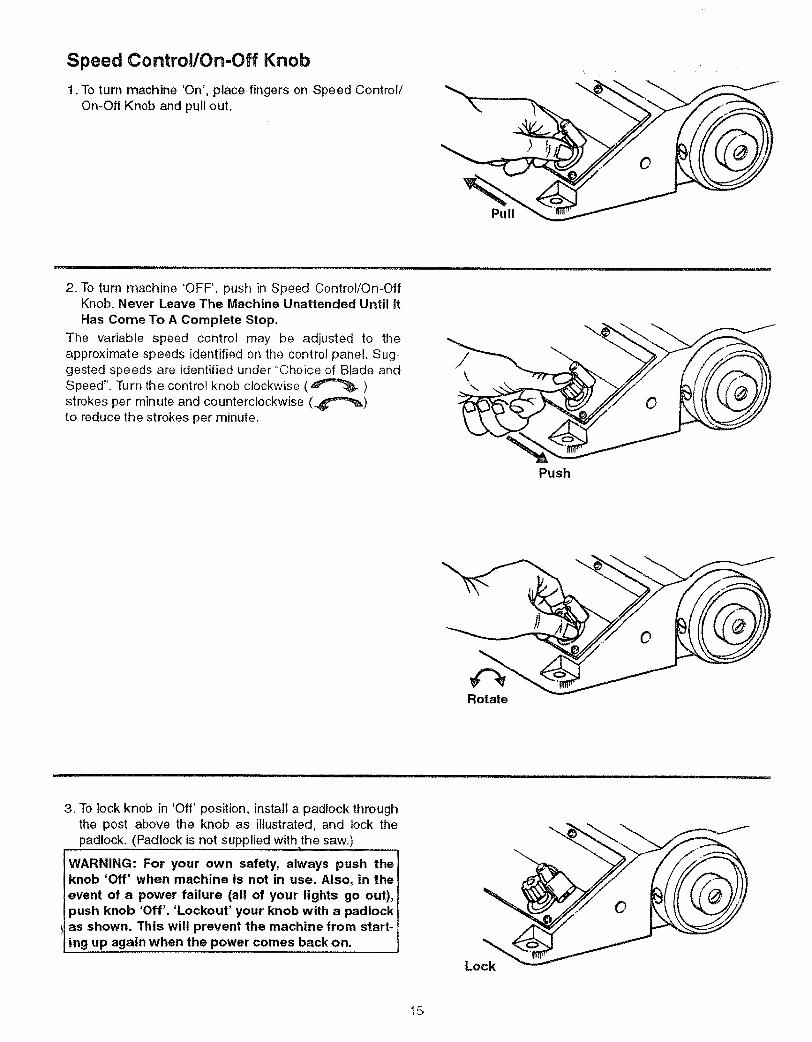
Speed Control/On-Off Knob
1.:To turn machine 'On', place fingers on Speed Control/On-Off Knob and pull out.
2. To turn machine 'OFF', push in Speed Control/On-OffKnob. Never Leave The Machine Unattended Until ItHas Come To A Complete Stop.
The variable speed control may be adjusted to theapproximate speeds identified on the contro! panel. Sug-gested speeds are identified under "Choice of Blade andSpeed". Turn the control knob clockwise (,_"_'_)
strokes per minute and counterclockwise (_"_)to reduce the strokes per minute.
\,,.
Push
Rotate
3. To lock knob in 'Off' position, install a padlock through
the post above the knob as illustrated, and lock the
padlock. (Padlock is not supplied withthe saw.)
WARNING: For your own safety, always push the
knob 'Off' when machine is not in use, Also, in the
event of a power failure (all of your lights go out),
push knob 'Off'. 'Lockout' your knob with a padlock
as shown. This will prevent the machine from start-
ing up again when the power comes back on.
15

3. Use a blade that will have at least 2 teeth in the mate-dal at ail times.
4, Use thin, narrow blades for tight radius work, and thi¢_wide blades for large curves and straight cuts.
Listed below are examples of some blades and their intended uses: ....
Pin and Plain end Biades
:'Teeth/inch Width Thickness
i, .... ha-20 .__2 .012"
15 : _110_'..... .0t 8"
Speed : _ _ Application
500-600 Tight radius work; 3/32" to 1/8' wood veneer, wood,
bone, fiber, plastics, non-ferrous metals, etc.
12:5
11.510
.038"
.053'_.110"
+:+o666'
.0i8"!
:,018"
600-1200
1200-1700
Close radius cutting in materials 3/32" to 1/2" thick.Good for hard and soft wood, bone, horn, plastics, etc.
For hard and soft woods and woodlike products3/16" to 2".
16
Basic Saw Operations- ................
=_lease, read and understand the following items aboutbur scroll saw before attempting to use the saw.
1. The saw does not Cut wood by itself. You allow thesaw to cut wood by guiding the wood into the bladeas it moves.
2. The blade teeth cut wood _ on the down stroke.
3. You must guide the wood into the blade slowlybecause the teeth of the blade are very small andthey can only remove wood when they are on thedown stroke.
4. There is a learning curve for each person who wantsto use this saw. During that period of time it isexpected that some blades will break until you learnhow to use the saw and receive the greatest benefitfrom the blades.
5. Best results are achieved when cutting wood lessthan one inch thick.
6. When cutting wood thicker than one inch the usermust guide the wood very, very slowly into the bladeand take extra care not to bend or twist the bladewhile cutting in order to maximize blade life.
7. Teeth on scroll saw blades wear out and as suchmust be replaced frequently for best cutting results.Scroll saw blades generally stay sharp for 1/2 hour to
', 2 hours of cutting.
8. To get accurate cuts, be prepared to compensate _orblade's tendency to follow the wood grain as you arecutting.
9. This scroll saw is intended to cut wood, wood likeproducts, plastics and non-ferrous metals.
10. When choosing a blade to use with your scroll saw,consider the following carefully.
o Very fine, narrow blades should be used to scroll cutin thin wood 1/4 inch thick or less.
• To cut wood over 1/4 inch thick, use wider blades.
o Most blade packages state the size or thickness ofwood which that blade is intended to cut, and the
radius, size of curve, which can be cut with that
blade.
• Wider blades can't cut curves as tight or small asthinner blades.
• Narrower blades work well only on thinner woodmaterial.
This saw uses 5 inch long, pin end type, blades only.See your Sears Retail Store for accessory blades.
Blades wear taster when cutting plywood, which isvery abrasive; when sawing wood which is thickerthan the 7/8 inch blade stroke; and when sawinghardwood, or when side pressure is placed on theblade.
Before Each Use:
inspect your saw.
Disconnect The Saw. To avoid injury from accidentalstarting, turn the switch "OFF", unplug the saw beforechanging the setup, removing covers, guards or blade.
CHECK DAMAGED PARTS. Check for:
o Alignment of moving parts.
o Binding of moving parts.
° Broken parts.o Stable mounting.
o Any other conditions that may affect the way the sawworks.
If any part is missing, bent or broken in any way, or anyelectrical parts don't work properly, turn the saw off andunplug the saw. Replace damaged, missing or failed
arts before using the saw again. Keep Guard In Placend in working order
Maintain Tools With Care
Keep the saw clean for best and safest performance.Follow instructions for lubricating.
Remove Adjusting Keys And Wrenches from tootbefore turning it on.
To avoid injury from jams, slips or thrown pieces:
• Choose the right size and style blade for the materialand the type of cutting you plan to do.
° Use Only Recommended Accessories. (See page21). Consult this Owner's manual for recommendedaccessories. Follow the instructions that come with theaccessories. The use of improper accessories maycause risk of injury to persons.
° Make sure the blade teeth point downward, toward thetable.
o Make sure the blade tension is properly adjusted.
° Keep Work Area Clean. Cluttered areas and benchesinvite accidents. Floor must not be slippery,
To avoid burns or other fire damage, never use the sawnear flammable liquids, vapors or gases.
17

Usel extra caution With :/large, very smal] orawkward workpieces:
owners
while
Av'oid Accidental Starting.: Make sure switch is "OFF"
before plugging Saw into a power outlet.
Plan your work;
o Use The Right Tool, Don't force tool or attachment todoa job it Was not designed todo.
,*use this scrolt saw to cut only wood, wood-like prod-ucts, plastics and non-ferrous metals.
CAUTION: This saw is NOT designed for cutting fer-rous metals like iron or steel. When cutting non-fer-rous metals (brass, :copper and aluminum, etc.),metal shavings can react with wood dust and start afire. To avoid this:
-Remove all traces of wood dust from inside thesaw.
• Remove all traces of metal dust from on or around
the saw before sawing wood again;
Dress for safety.Any power saw can throw foreign objects into the eyes.This can cause permanent eye damage. Wear safetygoggles (not glasses) that comply with ANSI Z87.1(shown on package), Everyday eyeglasses have only
Neve!_uSethis:t00t t0 finish pieces too small to hold bvha a - ....
Use extra supports (tables, _saw horses, blocks etc.)for:any workpiece large enough to tip when not helddown to the table top.
o Never use another person as a substitute for a tableextension, or as additional support for a workpiece orto help feed, support or pull the workpiece
o When cutting irregularly shaped workpieces, plan you rwork so it will not pinch the blade. A piece of molding,for example, must lay flat or be held by a fixture or jigthat will not let it twist, rock or slip while being cut.
• Properly support round material such as dowel rods ortubing. They have a tendency to roll during a cut,causing the blade to "bite". To avoid this, always use a"V" block,
° Cut only one workpiece at a time.
° Clear everything except the workpiece and relatedsupport devices off the table before turning the saw on.
Plan the way you will hold the workpiece from start tofinish.
Do not hand hold pieces so small that your fingers will gounder the blade guard. Use jigs or fixtures to hold thework and keep your hands away from the blade.
Avoid awkward operations and hand positions where asudden slip could cause fingers or hand to move Ontothe!blade.
Don't Overreach. Keep good footing and balance.
Keep your face and body to one side of blade, out of lineimpact resistant lenses. They are not safety glassesi:: ....with_apossible thrown piece if the blade should break.Safety goggles: are available :at Sears Retail Stores.Glasses or goggles not in compliance with ANSi Z87.1could seriously hurt you when they break_
• Do not wear loose clothing, gloves, neckties or jewelry(rings, wristwatches). They can get Caught anddrawyou into moving parts,
"* Wear non-slip footwear.
• Tie back long hair.
° Roll long sleeves above the elbow,
° Noise levels vary widely. To avoid possible hearingdamage, wear ear plugs or muffs when using saw forhours at a time.
• For dusty operations, wear a dust mask along with thesafety goggles.
Inspect your workpiece.
Make sure there are no nails or foreign objects in the partof the workpiece to be cut.
18
Whenever Saw Is Running
iWARNING: Don't let familiarity (gained from fre- I
quent use of your saw) cause a careless mistake. A Iicareless fraction of a second is enough to cause a Il
I severe injury.
Before starting your cut, watch the saw while it runs. If itmakes an unfamiliar noise or vibrates a lot, stop immedi-ately. Turn the saw off. Unplug the saw. Do not restartuntil finding and correcting the problem.
Keep Children Away. Keep all visitors a safe distancefrom the saw. Make sure bystanders are clear of the sawand workpiece.
Don't Force Tool. It will do the job better and safer at itsdesigned rate. Feed the workpiece into the saw bladeonly fast enough to let it cut without bogging down orbinding.
Before freeing any jammed material:
• Turn switch "OFF".
o Unplug saw.
• Wait for al! moving parts to stop.
When backing up the workpiece, the blade may bindin the kerr (cut). This is usually caused by sawdustclogging up the kerf. If this happens:
* Turn switch "OFF".
- Unplug saw.
o Wait for al! moving parts to stop.
o With a flat blade screwdriver, turn the motor by handwhile backing up the workpiece.
Before removing loose pieces from the table, turnsaw off and wait for all moving parts to stop.
Before Leaving The Saw:
° Wait for all moving parts to stop.
Make Workshop Child-proof. Unplug the saw. Lock theshop or ON/OFF knob, Store the key away from childrenand others not qualified to use the tool.
Making interior Scroll Cuts
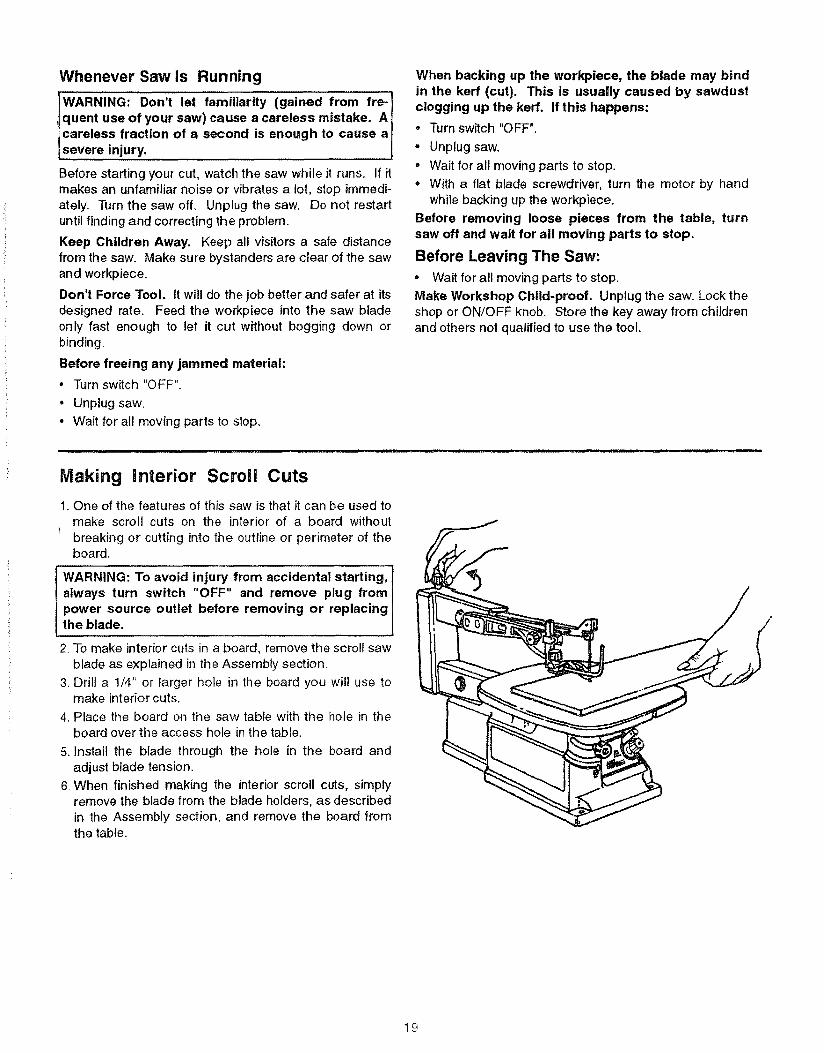
1. One of the features of this saw is that it can be used tomake scroll cuts on the interior of a board withoutbreaking or cutting into the outline or perimeter of theboard.
WARNING: To avoid injury from accidental starting,always turn switch "OFF" and remove plug frompower source outlet before removing or replacingthe blade.
2, To make interior cuts in a board, remove the scroll sawblade as explained in the Assembly section,
3. Drill a 1/4" or larger hole in the board you wil! use tomake interior cuts.
4. Place the board on the saw table with the hole in theboard over the access hole in the table.
5. Install the blade through the hole in the board andadjust blade tension.
6. When finished making the interior scroll cuts, simplyremove the blade from the blade holders, as describedin the Assembly section, and remove the board fromthe table.
19
pastewax onthe wo_k:tabte willcut _to'glide:smooth y across the
i
The motor bearings are permanently lubricated andrequire no further lubrication,
D0not attempt to oil the motor bearings or service them0t0rinternalpartsi
WARNING: ifthe power cord is worm, cut or dam- iaged inany way, have it replaced immediately. it WARNING: To avoid fire or electrocution, reassem- iI bie electric parts with only approved service parts._[Reassemble exactly as originally assembled. |
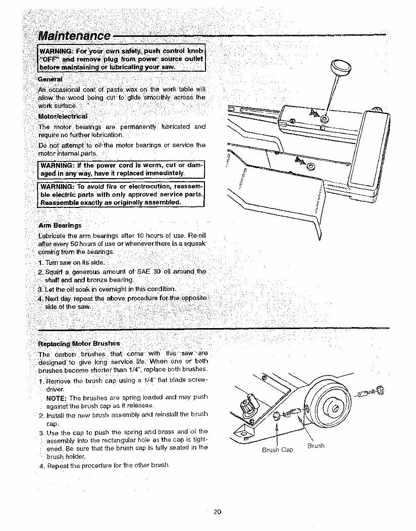
Arm Bearings
Lubricate the arm bearings after 10 _ours of use. Re-oilafter every 50 hours of use or whenever there is a squeakcoming from the bearings_
1. Turn saw on its side. _
2_Squirt a generous amount 0f SAE 30 oil around the-::shaft end and bronze bearing._3_Let tl_e:oil soak inoVernight in this condition.
4;Next day repeat the above procedure for::the opposite
with this saw are
designed to give long service life. When one or bothbrushes become shorter than 1/4", replace both brushes.
1. Remove the brush cap using a 1/4" flat blade screw-
driver.
NOTE: The brushes are spring loaded and may push
against the brush cap as it releases.
2. Install the new brush assembly and reinstall the brush
cap.
3. Use the cap to push the spring and brass end of the
assembly into the rectangular hole as the cap is tight-ened. Be sure that the brush cap is fully seated in the
brush hoider.
4. Repeat the procedure for the ether brush.
Brush Cap
\\,Brush
20
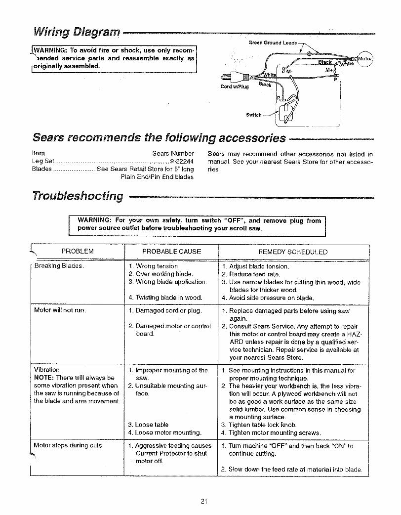
Wiring Diagram ...........
/ARNING: To avoid fire or shock, use only recom-_ended service parts and reassemble exactly as
[originally assembled.
_J
Sears recommends the following accessoriesItem Sears NumberLeg Set ............................................................... 9-22244Blades ....................... See Sears Retail Store for 5" long
Plain End/Pin End blades
Sears may recommend other accessories not listed inmanual, See your nearest Sears Store for other accesso-ries.
Troubleshooting ..............................................
t WARNING: For your own safety, turn switch "OFF", and remove plug from Ipower source outlet before troubleshooting your scroll saw.
L PROBLEM PROBABLE CAUSE
Breaking B'iades, 1.
Motor will not run.
Vibration
NOTE: There will always besome vibration present whenthe saw is running because ofthe blade and arm movement,
Wrong tension2. Over working blade.3. Wrong btade application.
4. Twisting blade in wood.
1, Damaged cord or plug.
2, Damaged motor or controlboard.
1, Improper mounting of thesaw.
2. Unsuitable mounting sur-face.
3. Loose table4. Loose motor mounting.
Motor stops during cuts 1:Aggressive feeding causesCurrent Protector to shutmotor off.
REMEDY SCHEDULED........................ ' "i
1. Adjust blade tension.2. Reduce feed rate.3. Use narrow blades for cutting thin wood, wide
blades for thicker wood.4. Avoid side pressure on blade.
1. Replace damaged parts before using sawagain.
2. Consult Sears Service. Any attempt to repairthis motor or control board may create a HAZ-ARD unless repair is done by a qualified ser_vice technician. Repair service is available atyour nearest Sears Store.
1. See mounting instructions in this manual forproper mounting technique.
2. The heavier your workbench is, the less vibra-tion will occur, A plywood workbench wilt notbe as good a work surface as the same sizesolid lumber. Use common sense in choosinga mounting surface.
3. Tighten table lock knob.4. Tighten motor mounting screws,
1. Turn machine "OFF" and then back "ON" tocontinue cutting.
2. Slow down the feed rate ot material into blade.
21
PoP_
48
/I
3O4O
39
32 38
37
51
1028
27
25
JJ
J
13 12
15 _10 " 14
11
18
1S16
19
22 2021
\ 2310 '\ 11
24 10
1 F

t',.3O3
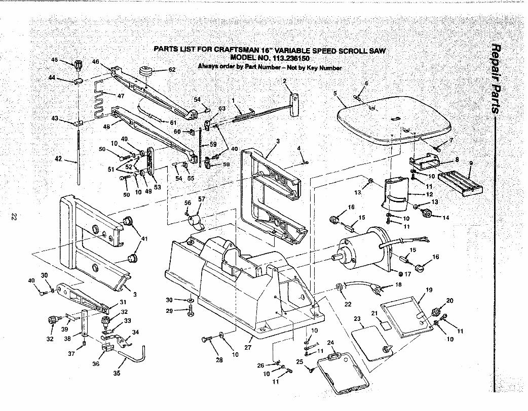
PARTS LIST FOR CRAFTSMAN 16" , RIABLE SPEED SCROLL SAW
MODEL NO. 113.236150
Always Order By Part Number-Not By Key Number
KeyNo.
12345678910111213141516!71819202!22232425262728293O3t32
Part No.
820733820333822426-1820376-2821673813249-131821701821708821707STD852005821389821702STD851006821697820322820324
822428821712821985821675821720819293821719821672817450-5821722821677821151-1820249-1STD85200682168382t697q
Description
Rod, Blade ChangeWrench, "T" Handle, 4ramHousing (includes Key #4 & 41)Screw Pan Hd Ty "TT" M4 x 0,7-28TablePin, Roll M5 x 25Screw, SupportGuide, DrawerDrawerLockwasher, M5Screw, Pan Hd M5 x 0,8-8Support, Scale
* Washer, 6mmKnobBrushCap, Brush
o Motor
Cord with PlugHousing, Control (includes label)KnobGasketGrommetBoard, ControllerCover, Switch BoxScrew, Pan Hd Self Tap M4 x 18indicator, TiltBase (Includes Labels)Screw Hex Hd M5 x 0.8-15Screw Hex Hd M6 x 1.0-20
* Lockwasher, M6Support, Hold DownKnob
Standard hardware item - may be purchased locally.t Stock item - may be secured through the Hardware department
of most Sears Retail Stores
Key lNo. i
33 134 i35 136 137 i38 I39 I4O t41 i42 143 !4445 t46 i47 I48 I49 I5O I51 I52 I53 I54 I55 i56 i57 I58 I59 t6o 161 162 l63 {
Part No. Description
821690821692821693821691818471-6821689821716820379-1821717821704816018816017821675-182166666061821668
818468818469817450-146-58600-3
Support, PlateSpring, Hold DownGuard, BladeClamp, Hold DownScrew, Hex Soc Set,M5 x 0.8-5Support BarPlate ClipScrew, Hex Soc Cap, M5 x 0.8-8Bearing, Flanged
Bolt, TensionWedge, TensionNut, TensionKnobArm, UpperSpringArm, LowerBearing, Ball 625ZZScrew, Hex Soc Cap, M5 x 0.8-16Screw, Pan Hd Serf Tap M4 x 16-8
* Washer, 4.2 x 10 x 0.9821706813249-1278203178184718217098203149-26877 t820316819248-18217O3820315SP5641
Link, ArmPin, Roll M5 x 14Clamp, Lower BladeScrew, Hex Soc Set, M6 x 1.0-6Coupling, EccentricHolder, Lower BladeBlade, Scroll SawClamp, Upper BladeHoseBellowsHolder, Upper BladeOwner's Manual (Not Illustrated)
;-A_'attempt to repair this motor may create a hazard unlessrepair is done by a qualified service technician. Repair serviceis available at your nearest Sears store.
113.236150your owner's manual for future reference
packed with your scroll saw. The instructions and illustrationsshown onblades.
scroll saw owner's manual for safety instructions and proper use of the scroll saw.
rBlades
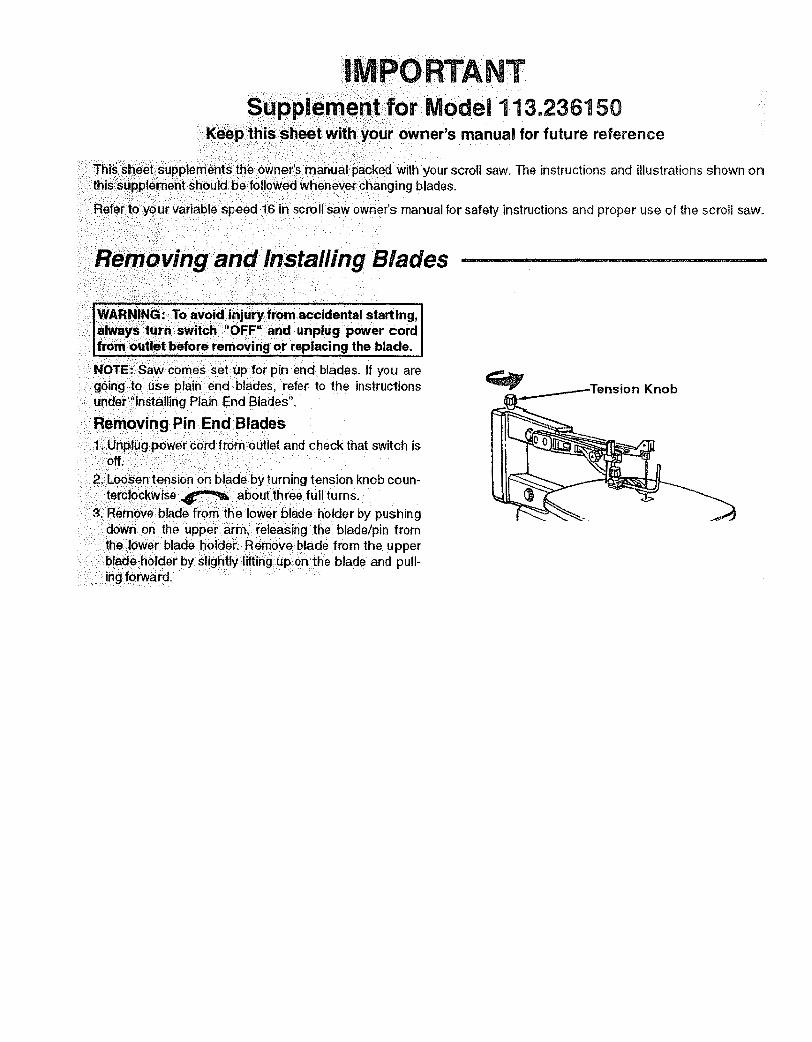
IWARNING :_To avoid i_iju_:from accidental starting, ilahNays 1urn switch _:,!OFF and :unplug power cord IIfrom_:outletbefore removing or replacing the blade, I
NOTE: Saw comes Set :uplfor pin end blades, tf you aregoing:to use plain end blades, refer to the instructionsunder:_'installingPlain End Blades".
Removing Pin End Blades
:1;,Unplug power cord from outlet and check that switch is0ffii_....
2_Loosen tension on blade by turning tension knob coun-
temlockwise _ about three full turns.3, Remove-blade ftorn :the iiower Blade holder by pushing
down on the upper arm, releasing the blade!pin fromthe lower blade holder_: Remove blade from the upperbtade holdei_by slightly;lifting, up on tt_e blade and pull-ing forward,
Knob
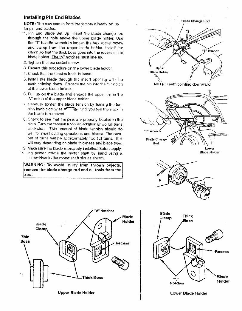
Installing Pin End Blades
NOTE: The saw come s from the factory already set upfor pin end blades.
4i, Pin End Blade Set Up: Insert the blade change rodthrough the hole above the upper blade holder, Usethe "T" handle wrench to loosen the hex socket screwand clamp from the upper blade holder, Install theclamp so that the thick boss goes into the recess in theblade holder. The "V" notches must line up.
2. Tighten the hex socket screw,
3. Repeat: this procedure on the lower blade holder.4. Check that the tension knob is loose.
5. Install the blade through the insert opening with theteeth pointing down. Engage the pin ir_to the "V" notchof the lower blade holder.
6. Pull up on the blade and engage the upper pin in the"V" notch of the upper blade holder.
7. Carefully tighten the blade tension by turning the ten-sion knob clockwise _ until you feel the slack inthe blade is removed.
8, Check to see that the pins are properly located in theslots, Turn the tension knob an additional two full turnsclockwise. This amount of blade tension should dowell for most cutting operations and blades. The num-ber of turns will be approximately two full turns. Thiswill vary depending on blade thickness and blade type.
9. Make sure the blade is properly installed, Before apply--'_ ing power, rotate the motor shaft by hand using a
screwdriver in t:he motor shaft slot as shown,
WARNING: To avoid injury from thrown objects,[remove the blade change rod and all toots from the[
tsaw.
Blade Change Rod
UpperBlade Holder
\NOTE: Teeth pointing downward.
"T" Wrenct
Blade ChangeRod
LowerBlade Holder
Blade
Thin Clamp_Boss
Notches
thick Boss
Upper Blade Holder
BladeHolder
BladeClamp Thick
,Boss
NotchesHolder
Lower Blade Holder
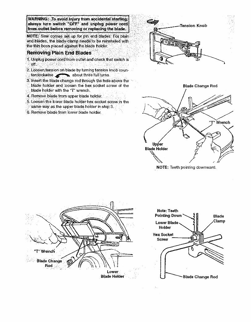
KnobZ
tel:clockwise _ about three full turns.3, Insert the blade change rod through the hole above the
blade holder and loosen the hex socket screw of theblade holder with the "T" wrench.
4!.Remove blade from upper blade holder.5i: Loosen th:e lower blade holder he× socket :screw in the
sarnewayaS the upper blade holder in step 3.61Remove blade from lower blade holder.
Blade Change Rod
UpperBlade Holder
\.
"T" Wrench
NOTE: Teeth pointing downward.
.... T":Wrencl_i
: : :Blad_Chang_.:-,Rod ::!::::::
:: =:: :
___lowerBlade Holder
Note:Teeth
Pointing
Holder
Hex SocketScrew
Blade
Blade Change Rod
Installing Plain End B|ades ..................
NOTE: For plain end blades, the thin boss of the blade
_.l_mp needs to be positioned against the blade holder.Plain End Blade Set Up: Insert the blade change rodthrough the hole above the upper blade holder. Usethe "T" handle wrench to loosen the hex socket screwand clamp from the upper blade holder. Install theclamp so that the thin boss is against the blade holder,and the beveled edge is in the corner of the bladeholder. The thin boss side of the blade clamp can beidentified by a circular impression placed on the sur-face.
2. Replace the hex socket screw.
3. Repeat this procedure on the lower blade holder.
4. Install the blade through the hole in the table and intothe lower blade holder. The blade teeth should pointdown. Position the blade end at the bottom of the blade
clamp and against the he× socket screw.
5. Tighten the hex socket screw, using the "T" wrench,while holding the blade change rod in position.
6. Use the same procedure to install the blade into theupper blade holder. Before tightening the socket hexscrew, adjust the position of the upper blade holder byturning the blade tension knob until the end of theblade is near the top of the blade holder.
7. Remove the "T' wrench and the blade change rod from
._._the blade hotder.Tighten the blade tension knob clockwiseuntil the blade is tensioned. The number of turns willbe approximately two full turns. This wil! vary depend-ing on blade thickness and blade type.
9, Make sure the blade is properly installed. Before apply-ing power, rotate the motor shaft by hand using ascrewdriver in the motor shaft as shown on the previ-ous page.
WARNING: To avoid injury from thrown objects,
remove the blade change rod and all tools from thesaw.
Blade Change Rod
!
UpperBlade Holder
\NOTE: Teeth pointing downward.
Lower8lade Holder
Note: TeethPointing Down _ Blade
Holder
Hsx Socket
Screw
Beveled EdgeCircular ImiDression
Blade Clam_ / t (_ _i_}B_l_d: r
Thin Boss
Upper Blade Holder
Form No. SP5766
Blade Clamp
CircularBeveledEdge Impression
BtadeHolder
Lower Blade Hotder
Printed in U.S.A. 7:,'94
SERVICE
MODEL NO.113.236150
HOW TO ORDERREPAIR PARTS
18 iNCH VARIABLESPEED SCROLL SAW
Now that you have purchased your scroll saw, should a needever exist for repair parts or service, simply contact any SearsService Center and most Sears, Roebuck and Co. stores, Besure to provide all pertinent facts when you call or visit.
The model number of your scroll saw will be found attached tothe right side of the arm housing.
WHEN ORDERING REPAIR PARTS, ALWAYS GIVE THE FOL-LOWING INFORMATION:
PART NUMBER PART DESCRIPTION
MODEL NUMBER113.236t50
NAME OF ITEMt6 INCH VARIABLE
SPEED SCROLL SAW
All parts listed may be ordered from any Sears Service Centerand most Sears stores. If the parts you need are not stocked
locally, your order will be electronically transmitted to a SearsRepair Parts Distribution Center for handling.
4p_... i iiiiiiiiiiiiii iiii _ _ ..................... iiii ii i i¸111111111/i/11 ii ii , iii
Sold by SEARS, ROEBUCK AND CO., Chicago, II. 60684 U.S.A.
Part No. SP5641 Form No. SP5641 4194
Ji,