Embed Size (px)
Citation preview
AirPrime MC8705 PCI Express Mini Card
Product Specification
2400057Rev. 5

Preface
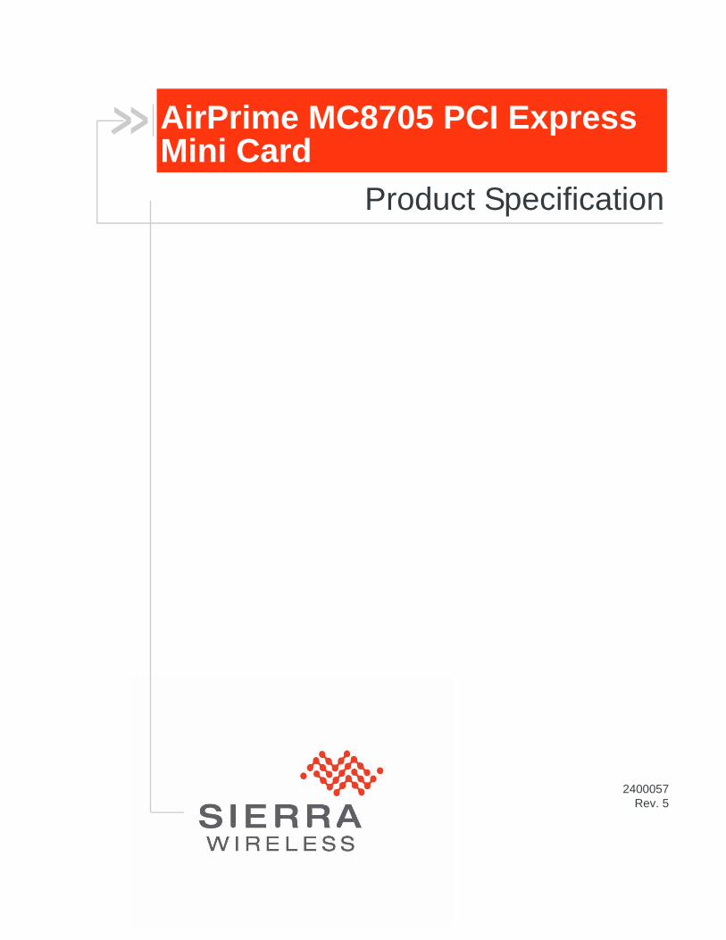
Important Notice
Due to the nature of wireless communications, transmission and reception of data can never be guaranteed. Data may be delayed, corrupted (i.e., have errors) or be totally lost. Although significant delays or losses of data are rare when wireless devices such as the Sierra Wireless modem are used in a normal manner with a well-constructed network, the Sierra Wireless modem should not be used in situations where failure to transmit or receive data could result in damage of any kind to the user or any other party, including but not limited to personal injury, death, or loss of property. Sierra Wireless accepts no responsibility for damages of any kind resulting from delays or errors in data transmitted or received using the Sierra Wireless modem, or for failure of the Sierra Wireless modem to transmit or receive such data.
Safety and Hazards
Do not operate the Sierra Wireless modem in areas where blasting is in progress, where explosive atmospheres may be present, near medical equipment, near life support equipment, or any equipment which may be susceptible to any form of radio interference. In such areas, the Sierra Wireless modem MUST BE POWERED OFF. The Sierra Wireless modem can transmit signals that could interfere with this equipment.
Do not operate the Sierra Wireless modem in any aircraft, whether the aircraft is on the ground or in flight. In aircraft, the Sierra Wireless modem MUST BE POWERED OFF. When operating, the Sierra Wireless modem can transmit signals that could interfere with various onboard systems.
Note: Some airlines may permit the use of cellular phones while the aircraft is on the ground and the door is open. Sierra Wireless modems may be used at this time.
The driver or operator of any vehicle should not operate the Sierra Wireless modem while in control of a vehicle. Doing so will detract from the driver or operator's control and operation of that vehicle. In some states and provinces, operating such communications devices while in control of a vehicle is an offence.
Limitation of Liability
The information in this manual is subject to change without notice and does not represent a commitment on the part of Sierra Wireless. SIERRA WIRELESS AND ITS AFFILIATES SPECIFICALLY DISCLAIM LIABILITY FOR ANY AND ALL DIRECT, INDIRECT, SPECIAL, GENERAL, INCIDENTAL, CONSEQUENTIAL, PUNITIVE OR EXEMPLARY DAMAGES INCLUDING, BUT NOT LIMITED TO, LOSS OF PROFITS OR REVENUE OR ANTICIPATED PROFITS OR REVENUE ARISING OUT OF THE USE OR INABILITY TO USE ANY SIERRA WIRELESS PRODUCT, EVEN IF SIERRA WIRELESS AND/OR ITS AFFILIATES HAS BEEN ADVISED OF THE POSSIBILITY OF SUCH DAMAGES OR THEY ARE FORESEEABLE OR FOR CLAIMS BY ANY THIRD PARTY.
Notwithstanding the foregoing, in no event shall Sierra Wireless and/or its affiliates aggregate liability arising under or in connection with the Sierra Wireless product, regardless of the number of events, occurrences, or claims giving rise to liability, be in excess of the price paid by the purchaser for the Sierra Wireless product.
Rev. 5 Mar.11 Proprietary and Confidential 3
AirPrime MC8705 PCI Express Mini Card Product Specification
Patents This product may contain technology developed by or for Sierra Wireless Inc. This product includes technology licensed from QUALCOMM® 3G. This product is manufactured or sold by Sierra Wireless Inc. or its affiliates under one or more patents licensed from InterDigital Group.
Copyright ©2011 Sierra Wireless. All rights reserved.
Trademarks Watcher® is a registered trademark of Sierra Wireless. Sierra Wireless, AirPrime and the Sierra Wireless logo are trademarks of Sierra Wireless.
Windows® is a registered trademark of Microsoft Corporation.
QUALCOMM® is a registered trademark of QUALCOMM Incorporated. Used under license.
Other trademarks are the property of their respective owners.
Contact Information
Consult our website for up-to-date product descriptions, documentation, application notes, firmware upgrades, troubleshooting tips, and press releases:
www.sierrawireless.com
Revision History
Sales Desk: Phone: 1-604-232-1488
Hours: 8:00 AM to 5:00 PM Pacific Time
E-mail: [email protected]
Post: Sierra Wireless13811 Wireless WayRichmond, BCCanada V6V 3A4
Fax: 1-604-231-1109
Web: www.sierrawireless.com
Revision number
Release date Changes
1 August 2010 Created document
2 October 2010 Marked pins 22 and 33 as ‘No connect’
3 January 2011 Replaced ‘tbd’ markers with current measurements
4 February 2011 Updated minimum voltage for pin 2, and marked pin 11 as No Connect in Table 4-1.Updated average GSM current in Table 6-3.
5 March 2011 Updated W_DISABLE# description in Control signals (20k pull-up resistor).Changed pins 30/32 to ‘NC’ from ‘Reserved’.
4 Proprietary and Confidential 2400057
Rev. 5 Ma
Contents
Introduction . . . . . . . . . . . . . . . . . . . . . . . . . . . . . . . . . . . . . . . . . . . . . . . . . . . . .9
Specifications at a glance. . . . . . . . . . . . . . . . . . . . . . . . . . . . . . . . . . . . . . . . 9
Support features. . . . . . . . . . . . . . . . . . . . . . . . . . . . . . . . . . . . . . . . . . . . . . 13
Supporting documents . . . . . . . . . . . . . . . . . . . . . . . . . . . . . . . . . . . . . . . . . 13
Accessories . . . . . . . . . . . . . . . . . . . . . . . . . . . . . . . . . . . . . . . . . . . . . . . . . 13
Ordering information. . . . . . . . . . . . . . . . . . . . . . . . . . . . . . . . . . . . . . . . . . . 13
Technology Overview . . . . . . . . . . . . . . . . . . . . . . . . . . . . . . . . . . . . . . . . . . . .15
HSPA+ . . . . . . . . . . . . . . . . . . . . . . . . . . . . . . . . . . . . . . . . . . . . . . . . . . . . . 15
HSPA . . . . . . . . . . . . . . . . . . . . . . . . . . . . . . . . . . . . . . . . . . . . . . . . . . . . . . 15
UMTS . . . . . . . . . . . . . . . . . . . . . . . . . . . . . . . . . . . . . . . . . . . . . . . . . . . . . . 15
GPRS/EDGE . . . . . . . . . . . . . . . . . . . . . . . . . . . . . . . . . . . . . . . . . . . . . . . . 15
Data rates . . . . . . . . . . . . . . . . . . . . . . . . . . . . . . . . . . . . . . . . . . . . . . . .16
Standards Compliance . . . . . . . . . . . . . . . . . . . . . . . . . . . . . . . . . . . . . . . . . . .17
UMTS WCDMA FDD specifications . . . . . . . . . . . . . . . . . . . . . . . . . . . . . . . 17
GSM/GPRS/EDGE specifications . . . . . . . . . . . . . . . . . . . . . . . . . . . . . . . . 19
Common UMTS WCDMA/GSM specifications . . . . . . . . . . . . . . . . . . . . . . 26
UMTS RABs supported . . . . . . . . . . . . . . . . . . . . . . . . . . . . . . . . . . . . . . . . 29
Short Message Service (SMS). . . . . . . . . . . . . . . . . . . . . . . . . . . . . . . . . . . 29
UMTS compliance acceptance and certification . . . . . . . . . . . . . . . . . . . . . 29
EU certification requirements . . . . . . . . . . . . . . . . . . . . . . . . . . . . . . . . . .29
FCC certification . . . . . . . . . . . . . . . . . . . . . . . . . . . . . . . . . . . . . . . . . . .30
r.11 Proprietary and Confidential 5
AirPrime MC8705 PCI Express Mini Card Product Specification
6
Electrical Specifications . . . . . . . . . . . . . . . . . . . . . . . . . . . . . . . . . . . . . . . . . 31
Host interface pin assignments . . . . . . . . . . . . . . . . . . . . . . . . . . . . . . . . . . 32
Host interface descriptions . . . . . . . . . . . . . . . . . . . . . . . . . . . . . . . . . . . 36
Power supply . . . . . . . . . . . . . . . . . . . . . . . . . . . . . . . . . . . . . . . . . . . . . . 36
USB interface . . . . . . . . . . . . . . . . . . . . . . . . . . . . . . . . . . . . . . . . . . . . . 36
USIM interface . . . . . . . . . . . . . . . . . . . . . . . . . . . . . . . . . . . . . . . . . . . . . 37
Control signals . . . . . . . . . . . . . . . . . . . . . . . . . . . . . . . . . . . . . . . . . . . . . 37
RF Specifications . . . . . . . . . . . . . . . . . . . . . . . . . . . . . . . . . . . . . . . . . . . . . . . 39
Power Consumption . . . . . . . . . . . . . . . . . . . . . . . . . . . . . . . . . . . . . . . . . . . . 43
GPS . . . . . . . . . . . . . . . . . . . . . . . . . . . . . . . . . . . . . . . . . . . . . . . . . . . . . . . . . . 47
Software Interface . . . . . . . . . . . . . . . . . . . . . . . . . . . . . . . . . . . . . . . . . . . . . . 49
Physical interface options . . . . . . . . . . . . . . . . . . . . . . . . . . . . . . . . . . . . . . 49
USB interface details . . . . . . . . . . . . . . . . . . . . . . . . . . . . . . . . . . . . . . . . . . 49
Support tools . . . . . . . . . . . . . . . . . . . . . . . . . . . . . . . . . . . . . . . . . . . . . . . . 49
Other features . . . . . . . . . . . . . . . . . . . . . . . . . . . . . . . . . . . . . . . . . . . . . . . 50
Customization . . . . . . . . . . . . . . . . . . . . . . . . . . . . . . . . . . . . . . . . . . . . . 50
Mechanical and Environmental Specifications . . . . . . . . . . . . . . . . . . . . . . . 51
Labeling . . . . . . . . . . . . . . . . . . . . . . . . . . . . . . . . . . . . . . . . . . . . . . . . . . . . 53
Approvals . . . . . . . . . . . . . . . . . . . . . . . . . . . . . . . . . . . . . . . . . . . . . . . . . . . . . 55
Additional Requirements . . . . . . . . . . . . . . . . . . . . . . . . . . . . . . . . . . . . . . . . . 57
Testing assistance provided by Sierra Wireless . . . . . . . . . . . . . . . . . . . . . 57
Integration requirements . . . . . . . . . . . . . . . . . . . . . . . . . . . . . . . . . . . . . . . 57
IOT/Operator . . . . . . . . . . . . . . . . . . . . . . . . . . . . . . . . . . . . . . . . . . . . . . . . 57
Data Rates . . . . . . . . . . . . . . . . . . . . . . . . . . . . . . . . . . . . . . . . . . . . . . . . . . . . . 59
HSDPA throughput . . . . . . . . . . . . . . . . . . . . . . . . . . . . . . . . . . . . . . . . . . . 59
Proprietary and Confidential 2400057
Contents
HSUPA throughput . . . . . . . . . . . . . . . . . . . . . . . . . . . . . . . . . . . . . . . . . . . . 60
UMTS throughput . . . . . . . . . . . . . . . . . . . . . . . . . . . . . . . . . . . . . . . . . . . . . 60
EDGE data throughput . . . . . . . . . . . . . . . . . . . . . . . . . . . . . . . . . . . . . . . . . 60
GPRS data throughput . . . . . . . . . . . . . . . . . . . . . . . . . . . . . . . . . . . . . . . . . 61
Multi-slot class definitions. . . . . . . . . . . . . . . . . . . . . . . . . . . . . . . . . . . . . . . 61
WWAN Frequency Bands . . . . . . . . . . . . . . . . . . . . . . . . . . . . . . . . . . . . . . . . .63
Acronyms . . . . . . . . . . . . . . . . . . . . . . . . . . . . . . . . . . . . . . . . . . . . . . . . . . . . .67
Rev. 5 Mar.11 Proprietary and Confidential 7

AirPrime MC8705 PCI Express Mini Card Product Specification
8 Proprietary and Confidential 2400057
Rev. 5 Ma
1
1: IntroductionThe Sierra Wireless AirPrime® MC8705 PCI Express Mini Card is a compact, lightweight, wireless UMTS-based modem. It provides GPS, EDGE, GPRS, GSM, WCDMA, HSDPA, HSUPA, and HSPA+ connectivity for portable and handheld computers, point-of-sale devices, telemetry products and other machine-to-machine and vertical applications over several radio frequency bands:• GSM, GPRS, EDGE850 MHz, 900 MHz, 1800 MHz, 1900 MHz
• UMTS WCDMA/HSDPA/HSUPA/HSPA+800 MHz, 850 MHz, 900 MHz, 1900 MHz, 2100 MHz
• Receive diversityOptimized for diversity on 800, 850, 900, 1900 and 2100 MHz
• GPS1575.42 MHz
The modem, based on Qualcomm's MDM8200A baseband processor, supports data operation on HSPA+, HSDPA, HSUPA, WCDMA, EDGE, and GPRS networks.
Specifications at a glance
This document describes high-level application and hardware interface requirements for integrating the MC8705 into a host product.
For more detailed information, see Supporting documents on page 13.
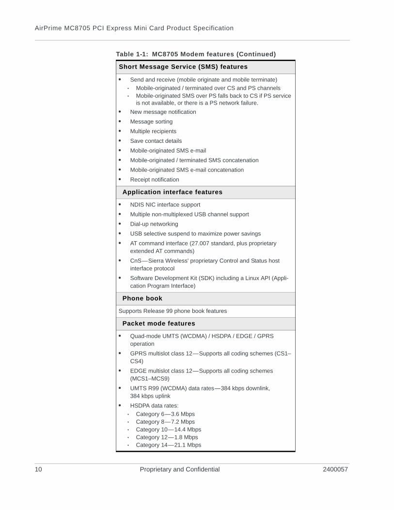
Table 1-1: MC8705 Modem features
Physical features
• Small form factor—conforms to F1 as specified in PCI Express Mini Card Electromechanical Specification Revision 1.2
• Two U.FL RF connector jacks
Electrical features
• Single supply voltage (VCC): 3.2V–3.6V
• Self-shielded—no additional shielding required
r.11 Proprietary and Confidential 9
AirPrime MC8705 PCI Express Mini Card Product Specification
Short Message Service (SMS) features
• Send and receive (mobile originate and mobile terminate)
· Mobile-originated / terminated over CS and PS channels· Mobile-originated SMS over PS falls back to CS if PS service
is not available, or there is a PS network failure.
• New message notification
• Message sorting
• Multiple recipients
• Save contact details
• Mobile-originated SMS e-mail
• Mobile-originated / terminated SMS concatenation
• Mobile-originated SMS e-mail concatenation
• Receipt notification
Application interface features
• NDIS NIC interface support
• Multiple non-multiplexed USB channel support
• Dial-up networking
• USB selective suspend to maximize power savings
• AT command interface (27.007 standard, plus proprietary extended AT commands)
• CnS—Sierra Wireless' proprietary Control and Status host interface protocol
• Software Development Kit (SDK) including a Linux API (Appli-cation Program Interface)
Phone book
Supports Release 99 phone book features
Packet mode features
• Quad-mode UMTS (WCDMA) / HSDPA / EDGE / GPRS operation
• GPRS multislot class 12—Supports all coding schemes (CS1–CS4)
• EDGE multislot class 12—Supports all coding schemes (MCS1–MCS9)
• UMTS R99 (WCDMA) data rates—384 kbps downlink, 384 kbps uplink
• HSDPA data rates:
· Category 6—3.6 Mbps· Category 8—7.2 Mbps· Category 10—14.4 Mbps· Category 12—1.8 Mbps· Category 14—21.1 Mbps
Table 1-1: MC8705 Modem features (Continued)
10 Proprietary and Confidential 2400057
Introduction
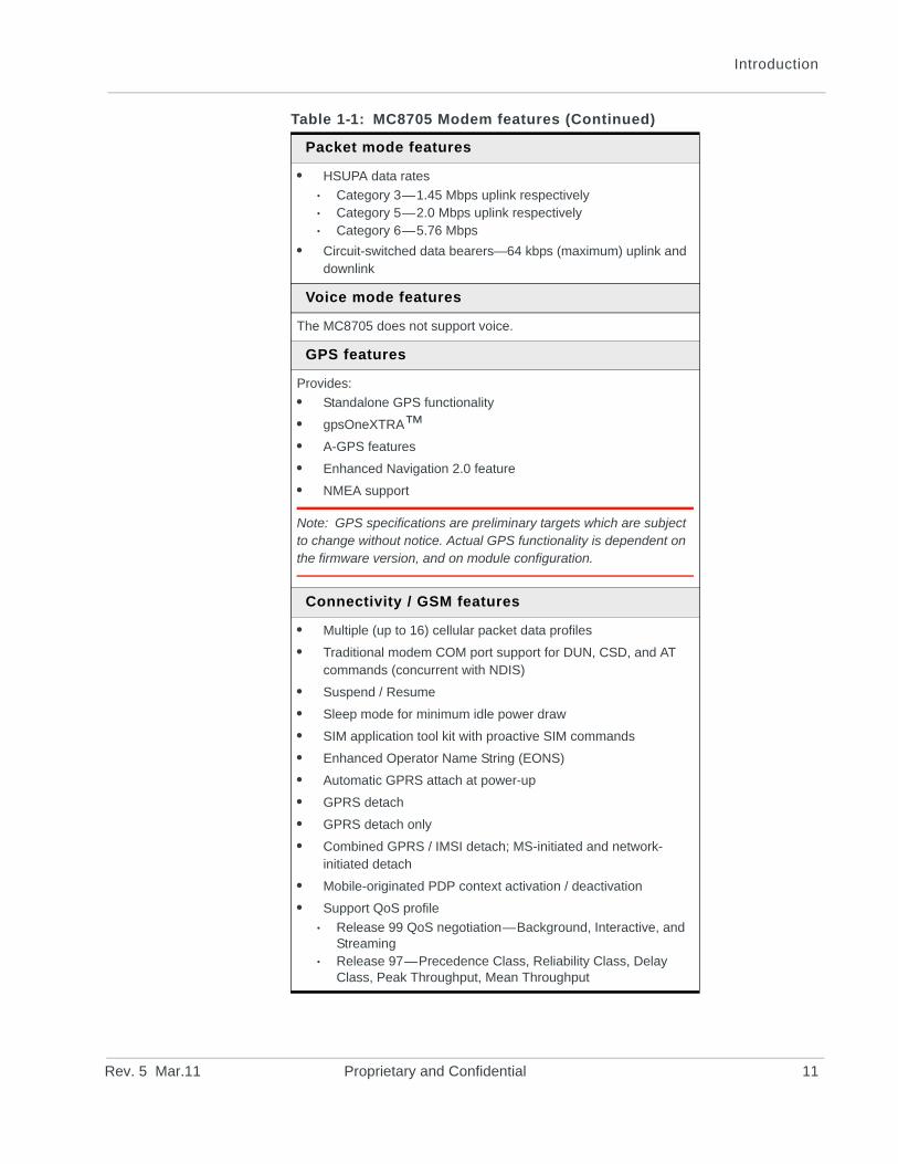
Packet mode features
• HSUPA data rates
· Category 3—1.45 Mbps uplink respectively· Category 5—2.0 Mbps uplink respectively· Category 6—5.76 Mbps
• Circuit-switched data bearers—64 kbps (maximum) uplink and downlink
Voice mode features
The MC8705 does not support voice.
GPS features
Provides:
• Standalone GPS functionality
• gpsOneXTRA™• A-GPS features
• Enhanced Navigation 2.0 feature
• NMEA support
Note: GPS specifications are preliminary targets which are subject to change without notice. Actual GPS functionality is dependent on the firmware version, and on module configuration.
Connectivity / GSM features
• Multiple (up to 16) cellular packet data profiles
• Traditional modem COM port support for DUN, CSD, and AT commands (concurrent with NDIS)
• Suspend / Resume
• Sleep mode for minimum idle power draw
• SIM application tool kit with proactive SIM commands
• Enhanced Operator Name String (EONS)
• Automatic GPRS attach at power-up
• GPRS detach
• GPRS detach only
• Combined GPRS / IMSI detach; MS-initiated and network-initiated detach
• Mobile-originated PDP context activation / deactivation
• Support QoS profile
· Release 99 QoS negotiation—Background, Interactive, and Streaming
· Release 97—Precedence Class, Reliability Class, Delay Class, Peak Throughput, Mean Throughput
Table 1-1: MC8705 Modem features (Continued)
Rev. 5 Mar.11 Proprietary and Confidential 11
AirPrime MC8705 PCI Express Mini Card Product Specification
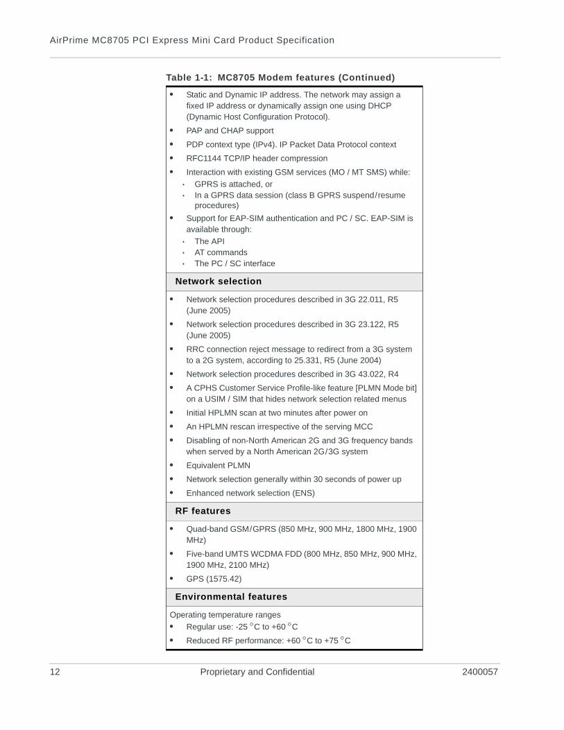
• Static and Dynamic IP address. The network may assign a fixed IP address or dynamically assign one using DHCP (Dynamic Host Configuration Protocol).
• PAP and CHAP support
• PDP context type (IPv4). IP Packet Data Protocol context
• RFC1144 TCP/IP header compression
• Interaction with existing GSM services (MO / MT SMS) while:
· GPRS is attached, or· In a GPRS data session (class B GPRS suspend/resume
procedures)
• Support for EAP-SIM authentication and PC / SC. EAP-SIM is available through:
· The API· AT commands· The PC / SC interface
Network selection
• Network selection procedures described in 3G 22.011, R5 (June 2005)
• Network selection procedures described in 3G 23.122, R5 (June 2005)
• RRC connection reject message to redirect from a 3G system to a 2G system, according to 25.331, R5 (June 2004)
• Network selection procedures described in 3G 43.022, R4
• A CPHS Customer Service Profile-like feature [PLMN Mode bit] on a USIM / SIM that hides network selection related menus
• Initial HPLMN scan at two minutes after power on
• An HPLMN rescan irrespective of the serving MCC
• Disabling of non-North American 2G and 3G frequency bands when served by a North American 2G/3G system
• Equivalent PLMN
• Network selection generally within 30 seconds of power up
• Enhanced network selection (ENS)
RF features
• Quad-band GSM/GPRS (850 MHz, 900 MHz, 1800 MHz, 1900 MHz)
• Five-band UMTS WCDMA FDD (800 MHz, 850 MHz, 900 MHz, 1900 MHz, 2100 MHz)
• GPS (1575.42)
Environmental features
Operating temperature ranges
• Regular use: -25 C to +60 C• Reduced RF performance: +60 C to +75 C
Table 1-1: MC8705 Modem features (Continued)
12 Proprietary and Confidential 2400057
Introduction
Support features
The MC8705 offers the following support features:
• Standard 1-year warranty
• Enabling software (drivers, SDK, etc.) for Linux
• USIM support
Supporting documents
There are several additional documents describing various aspects of the Mini Card, including design, usage, and integration issues. These documents (AT command references, integration guides, etc.) are available at www.sierrawireless.com/minicard. Contact your Sierra Wireless account representative to obtain access permission.
Accessories
The MC8705 Development Kit includes:
• Embedded Modem Interface Kit
• Documentation suite
• Initial allotment of support hours
• USB cable
Sierra Wireless also offers antennas.
Ordering information
To order, contact the Sierra Wireless Sales Desk at +1 (604) 232-1488 between 8 AM and 5 PM Pacific Time.
Rev. 5 Mar.11 Proprietary and Confidential 13
AirPrime MC8705 PCI Express Mini Card Product Specification
14 Proprietary and Confidential 2400057
Rev. 5 Ma
2
2: Technology OverviewHSPA+
HSPA+ is an enhanced version of HSPA (High Speed Packet Access), as defined by the 3rd Generation Partnership Project (3GPP) Release 7 UMTS Specification for Mobile Terminated Equipment. Using improved modulation schemes and refined data communication protocols, HSPA+ permits increased uplink and downlink data rates.
HSPA
HSPA is a third generation (3G) evolution of WCDMA that combines two extensions to UMTS—HSDPA (High Speed Downlink Packet Access) and HSUPA (High Speed Uplink Packet Access).
UMTS
The Universal Mobile Telecommunications System (UMTS) specification is the 3G mobile systems standard based on an evolution of GSM core network components. High-speed 3G systems implementing the UMTS standard enable improved performance for wireless data applications, delivery of enhanced multimedia content, and improved network capacity to support additional subscribers.
UMTS supports Quality of Service (QoS) classes that describe differing use requirements. From most to least delay-sensitive, the QoS classes are:
• Streaming—Preserves the time relation between information entities of the data stream.Example: streaming multimedia
• Interactive—Preserves the data integrity of information entities (request / response pattern).Examples: web browsing, network games
• Background—Preserves the data integrity of information entities. The destination is not expecting the data within a certain time.Example: downloading email
These classes support everything from time-insensitive background data transfer to more time-critical applications.
GPRS/EDGEGPRS and EDGE are 2G wireless technologies providing end-to-end packet data services through reuse of existing GSM infrastructure.
r.11 Proprietary and Confidential 15
AirPrime MC8705 PCI Express Mini Card Product Specification
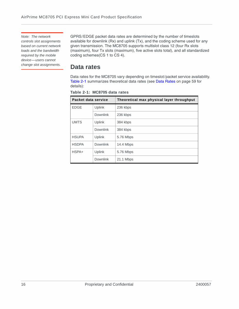
Note: The network controls slot assignments based on current network loads and the bandwidth required by the mobile device—users cannot change slot assignments.
GPRS/EDGE packet data rates are determined by the number of timeslots available for downlink (Rx) and uplink (Tx), and the coding scheme used for any given transmission. The MC8705 supports multislot class 12 (four Rx slots (maximum), four Tx slots (maximum), five active slots total), and all standardized coding schemes(CS 1 to CS 4).
Data rates
Data rates for the MC8705 vary depending on timeslot/packet service availability. Table 2-1 summarizes theoretical data rates (see Data Rates on page 59 for details):
Table 2-1: MC8705 data rates
Packet data service Theoretical max physical layer throughput
EDGE Uplink 236 kbps
Downlink 236 kbps
UMTS Uplink 384 kbps
Downlink 384 kbps
HSUPA Uplink 5.76 Mbps
HSDPA Downlink 14.4 Mbps
HSPA+ Uplink 5.76 Mbps
Downlink 21.1 Mbps
16 Proprietary and Confidential 2400057
Rev. 5 Ma
3
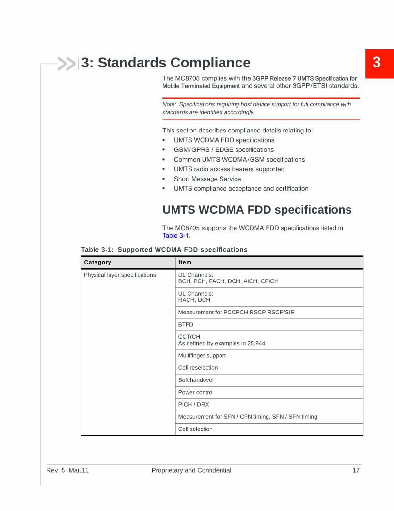
3: Standards ComplianceThe MC8705 complies with the 3GPP Release 7 UMTS Specification for Mobile Terminated Equipment and several other 3GPP/ETSI standards.Note: Specifications requiring host device support for full compliance with standards are identified accordingly.
This section describes compliance details relating to:
• UMTS WCDMA FDD specifications
• GSM/GPRS / EDGE specifications
• Common UMTS WCDMA/GSM specifications
• UMTS radio access bearers supported
• Short Message Service
• UMTS compliance acceptance and certification
UMTS WCDMA FDD specifications
The MC8705 supports the WCDMA FDD specifications listed in Table 3-1.
Table 3-1: Supported WCDMA FDD specifications
Category Item
Physical layer specifications DL Channels:BCH, PCH, FACH, DCH, AICH, CPICH
UL Channels:RACH, DCH
Measurement for PCCPCH RSCP RSCP/SIR
BTFD
CCTrCHAs defined by examples in 25.944
Multifinger support
Cell reselection
Soft handover
Power control
PICH / DRX
Measurement for SFN / CFN timing, SFN / SFN timing
Cell selection
r.11 Proprietary and Confidential 17
AirPrime MC8705 PCI Express Mini Card Product Specification
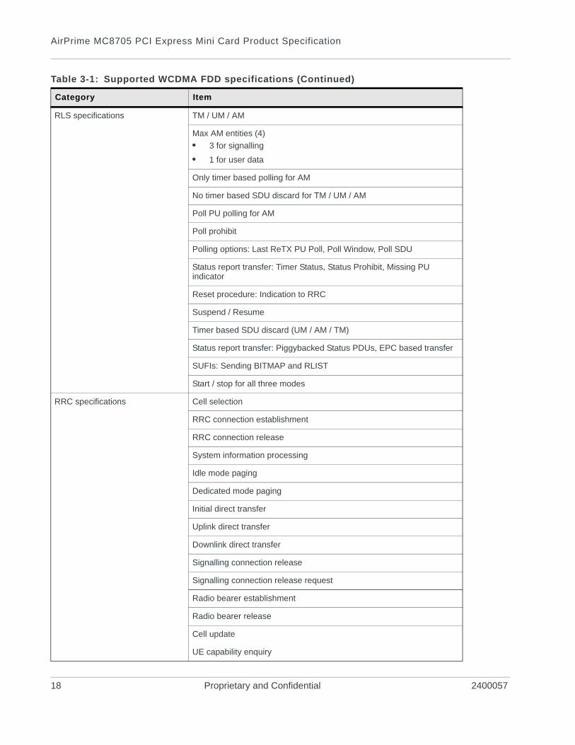
RLS specifications TM / UM / AM
Max AM entities (4)
• 3 for signalling
• 1 for user data
Only timer based polling for AM
No timer based SDU discard for TM / UM / AM
Poll PU polling for AM
Poll prohibit
Polling options: Last ReTX PU Poll, Poll Window, Poll SDU
Status report transfer: Timer Status, Status Prohibit, Missing PU indicator
Reset procedure: Indication to RRC
Suspend / Resume
Timer based SDU discard (UM / AM / TM)
Status report transfer: Piggybacked Status PDUs, EPC based transfer
SUFIs: Sending BITMAP and RLIST
Start / stop for all three modes
RRC specifications Cell selection
RRC connection establishment
RRC connection release
System information processing
Idle mode paging
Dedicated mode paging
Initial direct transfer
Uplink direct transfer
Downlink direct transfer
Signalling connection release
Signalling connection release request
Radio bearer establishment
Radio bearer release
Cell update
UE capability enquiry
Table 3-1: Supported WCDMA FDD specifications (Continued)
Category Item
18 Proprietary and Confidential 2400057
Standards Compliance
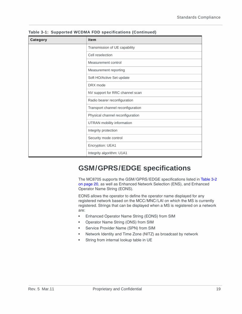
GSM/GPRS/EDGE specifications
The MC8705 supports the GSM/GPRS/EDGE specifications listed in Table 3-2 on page 20, as well as Enhanced Network Selection (ENS), and Enhanced Operator Name String (EONS).
EONS allows the operator to define the operator name displayed for any registered network based on the MCC/MNC/LAI on which the MS is currently registered. Strings that can be displayed when a MS is registered on a network are:
• Enhanced Operator Name String (EONS) from SIM
• Operator Name String (ONS) from SIM
• Service Provider Name (SPN) from SIM
• Network Identity and Time Zone (NITZ) as broadcast by network
• String from internal lookup table in UE
Transmission of UE capability
Cell reselection
Measurement control
Measurement reporting
Soft HO/Active Set update
DRX mode
NV support for RRC channel scan
Radio bearer reconfiguration
Transport channel reconfiguration
Physical channel reconfiguration
UTRAN mobility information
Integrity protection
Security mode control
Encryption: UEA1
Integrity algorithm: U1A1
Table 3-1: Supported WCDMA FDD specifications (Continued)
Category Item
Rev. 5 Mar.11 Proprietary and Confidential 19
AirPrime MC8705 PCI Express Mini Card Product Specification
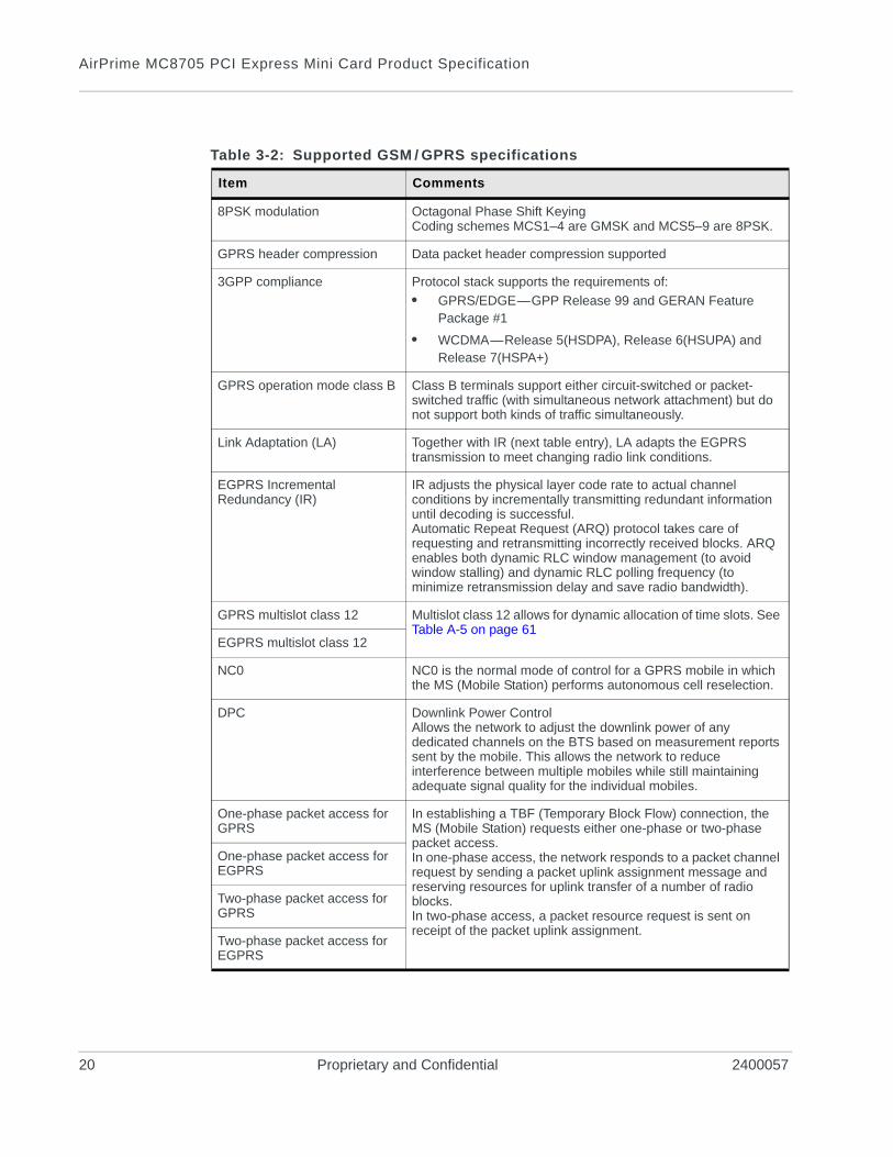
Table 3-2: Supported GSM / GPRS specifications
Item Comments
8PSK modulation Octagonal Phase Shift KeyingCoding schemes MCS1–4 are GMSK and MCS5–9 are 8PSK.
GPRS header compression Data packet header compression supported
3GPP compliance Protocol stack supports the requirements of:
• GPRS/EDGE—GPP Release 99 and GERAN Feature Package #1
• WCDMA—Release 5(HSDPA), Release 6(HSUPA) and Release 7(HSPA+)
GPRS operation mode class B Class B terminals support either circuit-switched or packet-switched traffic (with simultaneous network attachment) but do not support both kinds of traffic simultaneously.
Link Adaptation (LA) Together with IR (next table entry), LA adapts the EGPRS transmission to meet changing radio link conditions.
EGPRS Incremental Redundancy (IR)
IR adjusts the physical layer code rate to actual channel conditions by incrementally transmitting redundant information until decoding is successful.Automatic Repeat Request (ARQ) protocol takes care of requesting and retransmitting incorrectly received blocks. ARQ enables both dynamic RLC window management (to avoid window stalling) and dynamic RLC polling frequency (to minimize retransmission delay and save radio bandwidth).
GPRS multislot class 12 Multislot class 12 allows for dynamic allocation of time slots. See Table A-5 on page 61
EGPRS multislot class 12
NC0 NC0 is the normal mode of control for a GPRS mobile in which the MS (Mobile Station) performs autonomous cell reselection.
DPC Downlink Power ControlAllows the network to adjust the downlink power of any dedicated channels on the BTS based on measurement reports sent by the mobile. This allows the network to reduce interference between multiple mobiles while still maintaining adequate signal quality for the individual mobiles.
One-phase packet access for GPRS
In establishing a TBF (Temporary Block Flow) connection, the MS (Mobile Station) requests either one-phase or two-phase packet access.In one-phase access, the network responds to a packet channel request by sending a packet uplink assignment message and reserving resources for uplink transfer of a number of radio blocks.In two-phase access, a packet resource request is sent on receipt of the packet uplink assignment.
One-phase packet access for EGPRS
Two-phase packet access for GPRS
Two-phase packet access for EGPRS
20 Proprietary and Confidential 2400057
Standards Compliance
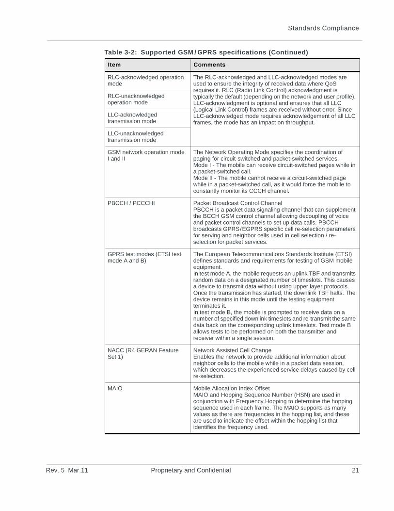
RLC-acknowledged operation mode
The RLC-acknowledged and LLC-acknowledged modes are used to ensure the integrity of received data where QoS requires it. RLC (Radio Link Control) acknowledgment is typically the default (depending on the network and user profile). LLC-acknowledgment is optional and ensures that all LLC (Logical Link Control) frames are received without error. Since LLC-acknowledged mode requires acknowledgement of all LLC frames, the mode has an impact on throughput.
RLC-unacknowledged operation mode
LLC-acknowledged transmission mode
LLC-unacknowledged transmission mode
GSM network operation mode I and II
The Network Operating Mode specifies the coordination of paging for circuit-switched and packet-switched services.Mode I - The mobile can receive circuit-switched pages while in a packet-switched call.Mode II - The mobile cannot receive a circuit-switched page while in a packet-switched call, as it would force the mobile to constantly monitor its CCCH channel.
PBCCH / PCCCHI Packet Broadcast Control ChannelPBCCH is a packet data signaling channel that can supplement the BCCH GSM control channel allowing decoupling of voice and packet control channels to set up data calls. PBCCH broadcasts GPRS/EGPRS specific cell re-selection parameters for serving and neighbor cells used in cell selection / re-selection for packet services.
GPRS test modes (ETSI test mode A and B)
The European Telecommunications Standards Institute (ETSI) defines standards and requirements for testing of GSM mobile equipment.In test mode A, the mobile requests an uplink TBF and transmits random data on a designated number of timeslots. This causes a device to transmit data without using upper layer protocols. Once the transmission has started, the downlink TBF halts. The device remains in this mode until the testing equipment terminates it.In test mode B, the mobile is prompted to receive data on a number of specified downlink timeslots and re-transmit the same data back on the corresponding uplink timeslots. Test mode B allows tests to be performed on both the transmitter and receiver within a single session.
NACC (R4 GERAN Feature Set 1)
Network Assisted Cell ChangeEnables the network to provide additional information about neighbor cells to the mobile while in a packet data session, which decreases the experienced service delays caused by cell re-selection.
MAIO Mobile Allocation Index OffsetMAIO and Hopping Sequence Number (HSN) are used in conjunction with Frequency Hopping to determine the hopping sequence used in each frame. The MAIO supports as many values as there are frequencies in the hopping list, and these are used to indicate the offset within the hopping list that identifies the frequency used.
Table 3-2: Supported GSM / GPRS specifications (Continued)
Item Comments
Rev. 5 Mar.11 Proprietary and Confidential 21
AirPrime MC8705 PCI Express Mini Card Product Specification
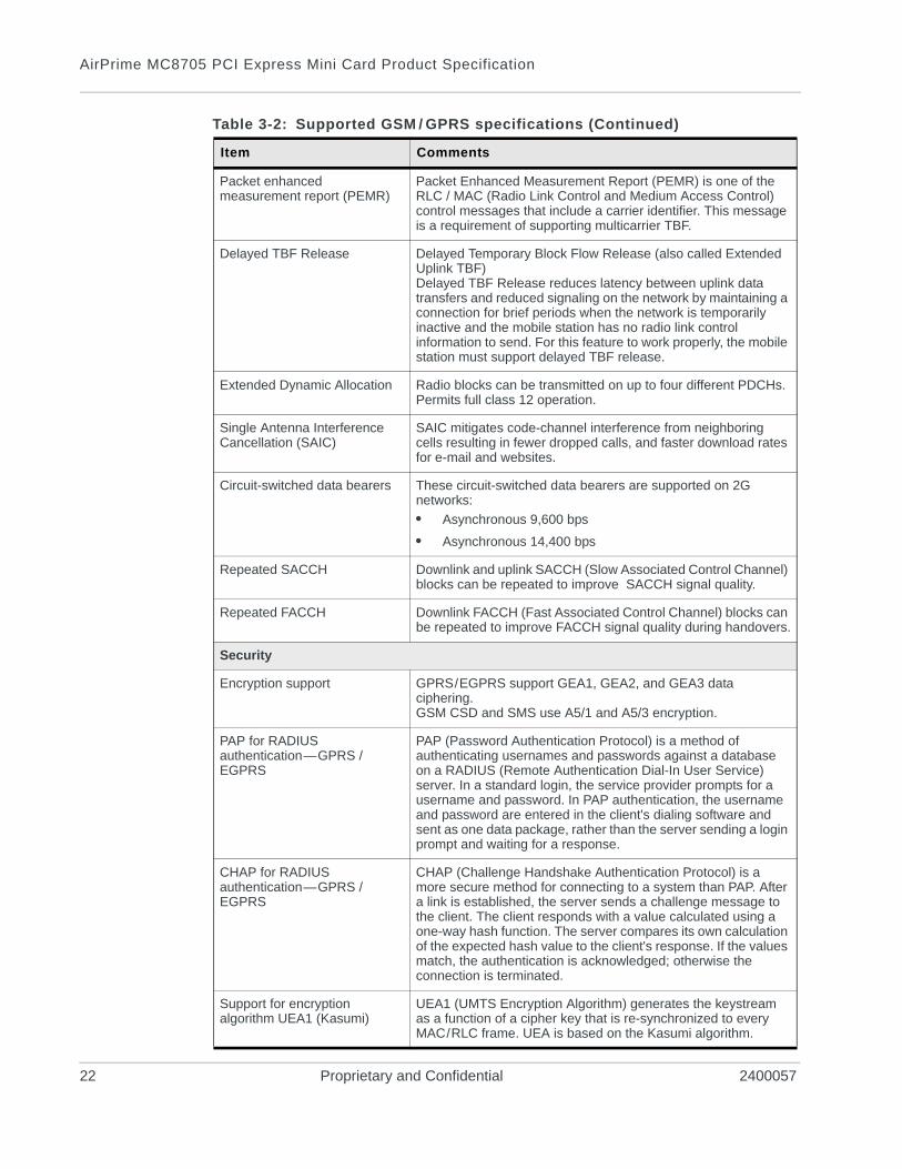
Packet enhanced measurement report (PEMR)
Packet Enhanced Measurement Report (PEMR) is one of the RLC / MAC (Radio Link Control and Medium Access Control) control messages that include a carrier identifier. This message is a requirement of supporting multicarrier TBF.
Delayed TBF Release Delayed Temporary Block Flow Release (also called Extended Uplink TBF)Delayed TBF Release reduces latency between uplink data transfers and reduced signaling on the network by maintaining a connection for brief periods when the network is temporarily inactive and the mobile station has no radio link control information to send. For this feature to work properly, the mobile station must support delayed TBF release.
Extended Dynamic Allocation Radio blocks can be transmitted on up to four different PDCHs. Permits full class 12 operation.
Single Antenna Interference Cancellation (SAIC)
SAIC mitigates code-channel interference from neighboring cells resulting in fewer dropped calls, and faster download rates for e-mail and websites.
Circuit-switched data bearers These circuit-switched data bearers are supported on 2G networks:
• Asynchronous 9,600 bps
• Asynchronous 14,400 bps
Repeated SACCH Downlink and uplink SACCH (Slow Associated Control Channel) blocks can be repeated to improve SACCH signal quality.
Repeated FACCH Downlink FACCH (Fast Associated Control Channel) blocks can be repeated to improve FACCH signal quality during handovers.
Security
Encryption support GPRS/EGPRS support GEA1, GEA2, and GEA3 data ciphering.GSM CSD and SMS use A5/1 and A5/3 encryption.
PAP for RADIUS authentication—GPRS / EGPRS
PAP (Password Authentication Protocol) is a method of authenticating usernames and passwords against a database on a RADIUS (Remote Authentication Dial-In User Service) server. In a standard login, the service provider prompts for a username and password. In PAP authentication, the username and password are entered in the client's dialing software and sent as one data package, rather than the server sending a login prompt and waiting for a response.
CHAP for RADIUS authentication—GPRS / EGPRS
CHAP (Challenge Handshake Authentication Protocol) is a more secure method for connecting to a system than PAP. After a link is established, the server sends a challenge message to the client. The client responds with a value calculated using a one-way hash function. The server compares its own calculation of the expected hash value to the client's response. If the values match, the authentication is acknowledged; otherwise the connection is terminated.
Support for encryption algorithm UEA1 (Kasumi)
UEA1 (UMTS Encryption Algorithm) generates the keystream as a function of a cipher key that is re-synchronized to every MAC/RLC frame. UEA is based on the Kasumi algorithm.
Table 3-2: Supported GSM / GPRS specifications (Continued)
Item Comments
22 Proprietary and Confidential 2400057
Standards Compliance
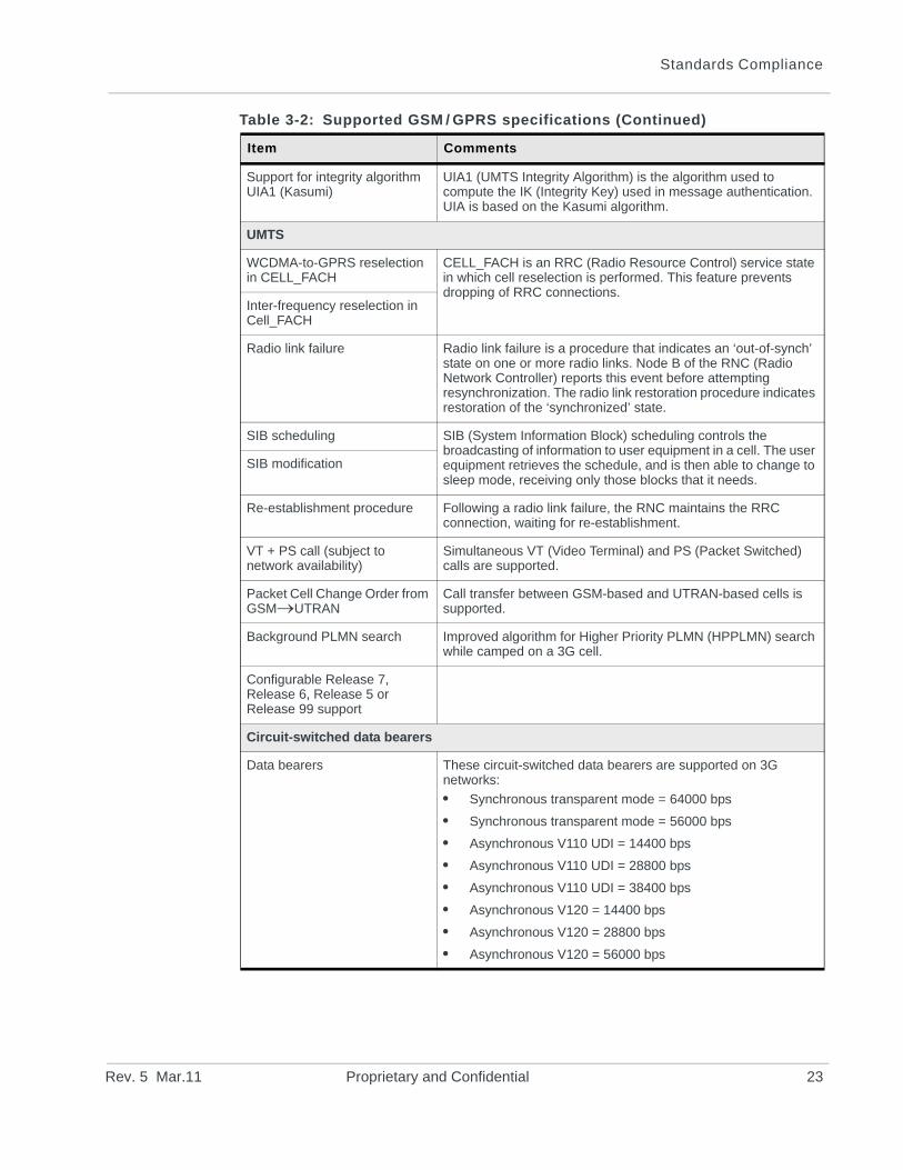
Support for integrity algorithm UIA1 (Kasumi)
UIA1 (UMTS Integrity Algorithm) is the algorithm used to compute the IK (Integrity Key) used in message authentication. UIA is based on the Kasumi algorithm.
UMTS
WCDMA-to-GPRS reselection in CELL_FACH
CELL_FACH is an RRC (Radio Resource Control) service state in which cell reselection is performed. This feature prevents dropping of RRC connections.
Inter-frequency reselection in Cell_FACH
Radio link failure Radio link failure is a procedure that indicates an ‘out-of-synch’ state on one or more radio links. Node B of the RNC (Radio Network Controller) reports this event before attempting resynchronization. The radio link restoration procedure indicates restoration of the ‘synchronized’ state.
SIB scheduling SIB (System Information Block) scheduling controls the broadcasting of information to user equipment in a cell. The user equipment retrieves the schedule, and is then able to change to sleep mode, receiving only those blocks that it needs.
SIB modification
Re-establishment procedure Following a radio link failure, the RNC maintains the RRC connection, waiting for re-establishment.
VT + PS call (subject to network availability)
Simultaneous VT (Video Terminal) and PS (Packet Switched) calls are supported.
Packet Cell Change Order from GSMUTRAN
Call transfer between GSM-based and UTRAN-based cells is supported.
Background PLMN search Improved algorithm for Higher Priority PLMN (HPPLMN) search while camped on a 3G cell.
Configurable Release 7, Release 6, Release 5 or Release 99 support
Circuit-switched data bearers
Data bearers These circuit-switched data bearers are supported on 3G networks:
• Synchronous transparent mode = 64000 bps
• Synchronous transparent mode = 56000 bps
• Asynchronous V110 UDI = 14400 bps
• Asynchronous V110 UDI = 28800 bps
• Asynchronous V110 UDI = 38400 bps
• Asynchronous V120 = 14400 bps
• Asynchronous V120 = 28800 bps
• Asynchronous V120 = 56000 bps
Table 3-2: Supported GSM / GPRS specifications (Continued)
Item Comments
Rev. 5 Mar.11 Proprietary and Confidential 23
AirPrime MC8705 PCI Express Mini Card Product Specification
HSDPA
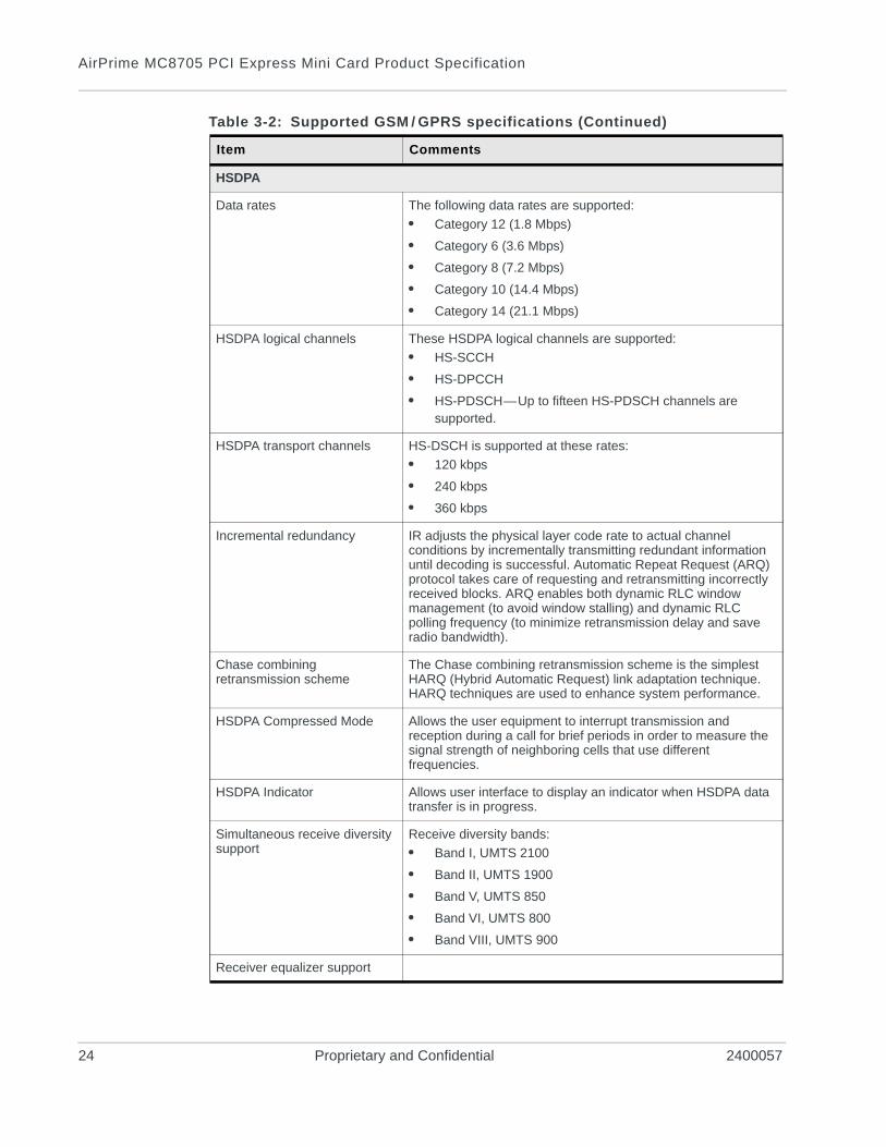
Data rates The following data rates are supported:
• Category 12 (1.8 Mbps)
• Category 6 (3.6 Mbps)
• Category 8 (7.2 Mbps)
• Category 10 (14.4 Mbps)
• Category 14 (21.1 Mbps)
HSDPA logical channels These HSDPA logical channels are supported:
• HS-SCCH
• HS-DPCCH
• HS-PDSCH—Up to fifteen HS-PDSCH channels are supported.
HSDPA transport channels HS-DSCH is supported at these rates:
• 120 kbps
• 240 kbps
• 360 kbps
Incremental redundancy IR adjusts the physical layer code rate to actual channel conditions by incrementally transmitting redundant information until decoding is successful. Automatic Repeat Request (ARQ) protocol takes care of requesting and retransmitting incorrectly received blocks. ARQ enables both dynamic RLC window management (to avoid window stalling) and dynamic RLC polling frequency (to minimize retransmission delay and save radio bandwidth).
Chase combining retransmission scheme
The Chase combining retransmission scheme is the simplest HARQ (Hybrid Automatic Request) link adaptation technique. HARQ techniques are used to enhance system performance.
HSDPA Compressed Mode Allows the user equipment to interrupt transmission and reception during a call for brief periods in order to measure the signal strength of neighboring cells that use different frequencies.
HSDPA Indicator Allows user interface to display an indicator when HSDPA data transfer is in progress.
Simultaneous receive diversity support
Receive diversity bands:
• Band I, UMTS 2100
• Band II, UMTS 1900
• Band V, UMTS 850
• Band VI, UMTS 800
• Band VIII, UMTS 900
Receiver equalizer support
Table 3-2: Supported GSM / GPRS specifications (Continued)
Item Comments
24 Proprietary and Confidential 2400057
Standards Compliance
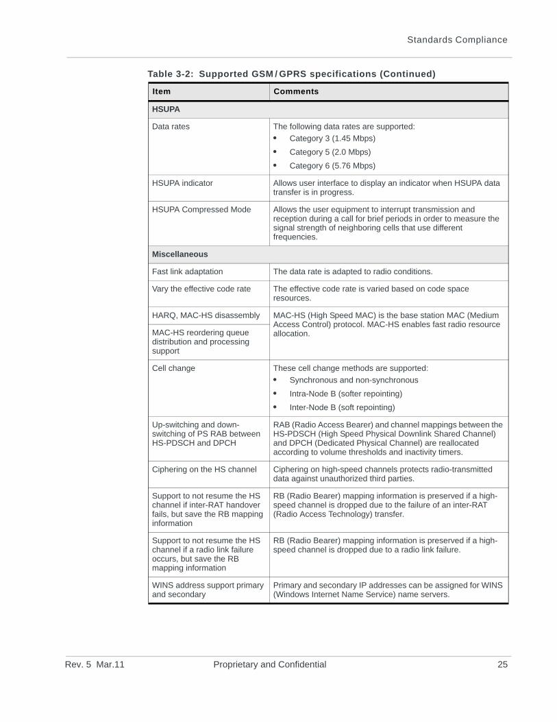
HSUPA
Data rates The following data rates are supported:
• Category 3 (1.45 Mbps)
• Category 5 (2.0 Mbps)
• Category 6 (5.76 Mbps)
HSUPA indicator Allows user interface to display an indicator when HSUPA data transfer is in progress.
HSUPA Compressed Mode Allows the user equipment to interrupt transmission and reception during a call for brief periods in order to measure the signal strength of neighboring cells that use different frequencies.
Miscellaneous
Fast link adaptation The data rate is adapted to radio conditions.
Vary the effective code rate The effective code rate is varied based on code space resources.
HARQ, MAC-HS disassembly MAC-HS (High Speed MAC) is the base station MAC (Medium Access Control) protocol. MAC-HS enables fast radio resource allocation.MAC-HS reordering queue
distribution and processing support
Cell change These cell change methods are supported:
• Synchronous and non-synchronous
• Intra-Node B (softer repointing)
• Inter-Node B (soft repointing)
Up-switching and down-switching of PS RAB between HS-PDSCH and DPCH
RAB (Radio Access Bearer) and channel mappings between the HS-PDSCH (High Speed Physical Downlink Shared Channel) and DPCH (Dedicated Physical Channel) are reallocated according to volume thresholds and inactivity timers.
Ciphering on the HS channel Ciphering on high-speed channels protects radio-transmitted data against unauthorized third parties.
Support to not resume the HS channel if inter-RAT handover fails, but save the RB mapping information
RB (Radio Bearer) mapping information is preserved if a high-speed channel is dropped due to the failure of an inter-RAT (Radio Access Technology) transfer.
Support to not resume the HS channel if a radio link failure occurs, but save the RB mapping information
RB (Radio Bearer) mapping information is preserved if a high-speed channel is dropped due to a radio link failure.
WINS address support primary and secondary
Primary and secondary IP addresses can be assigned for WINS (Windows Internet Name Service) name servers.
Table 3-2: Supported GSM / GPRS specifications (Continued)
Item Comments
Rev. 5 Mar.11 Proprietary and Confidential 25
AirPrime MC8705 PCI Express Mini Card Product Specification
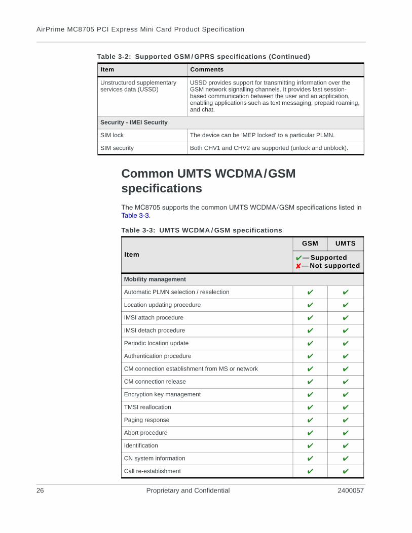
Common UMTS WCDMA/GSM specifications
The MC8705 supports the common UMTS WCDMA/GSM specifications listed in Table 3-3.
Unstructured supplementary services data (USSD)
USSD provides support for transmitting information over the GSM network signalling channels. It provides fast session-based communication between the user and an application, enabling applications such as text messaging, prepaid roaming, and chat.
Security - IMEI Security
SIM lock The device can be ‘MEP locked’ to a particular PLMN.
SIM security Both CHV1 and CHV2 are supported (unlock and unblock).
Table 3-2: Supported GSM / GPRS specifications (Continued)
Item Comments
Table 3-3: UMTS WCDMA / GSM specifications
Item
GSM UMTS
— Supported— Not supported
Mobility management
Automatic PLMN selection / reselection
Location updating procedure
IMSI attach procedure
IMSI detach procedure
Periodic location update
Authentication procedure
CM connection establishment from MS or network
CM connection release
Encryption key management
TMSI reallocation
Paging response
Abort procedure
Identification
CN system information
Call re-establishment
26 Proprietary and Confidential 2400057
Standards Compliance
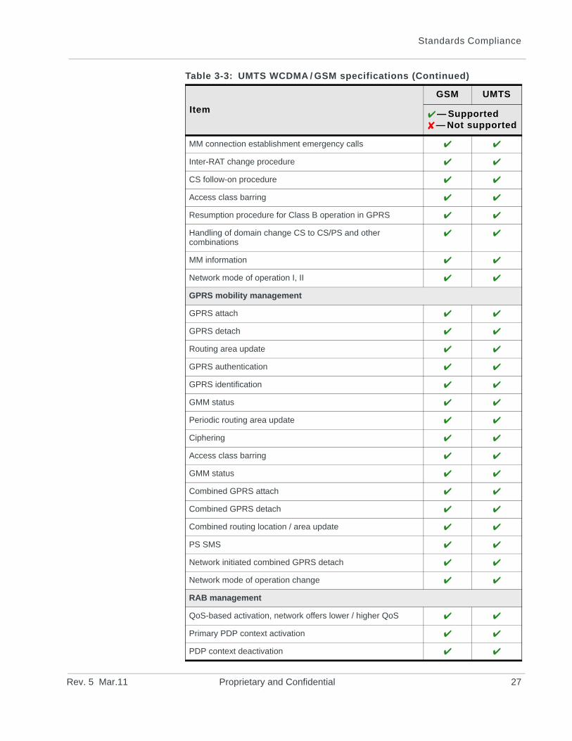
MM connection establishment emergency calls
Inter-RAT change procedure
CS follow-on procedure
Access class barring
Resumption procedure for Class B operation in GPRS
Handling of domain change CS to CS/PS and other combinations
MM information
Network mode of operation I, II
GPRS mobility management
GPRS attach
GPRS detach
Routing area update
GPRS authentication
GPRS identification
GMM status
Periodic routing area update
Ciphering
Access class barring
GMM status
Combined GPRS attach
Combined GPRS detach
Combined routing location / area update
PS SMS
Network initiated combined GPRS detach
Network mode of operation change
RAB management
QoS-based activation, network offers lower / higher QoS
Primary PDP context activation
PDP context deactivation
Table 3-3: UMTS WCDMA / GSM specifications (Continued)
Item
GSM UMTS
— Supported— Not supported
Rev. 5 Mar.11 Proprietary and Confidential 27
AirPrime MC8705 PCI Express Mini Card Product Specification
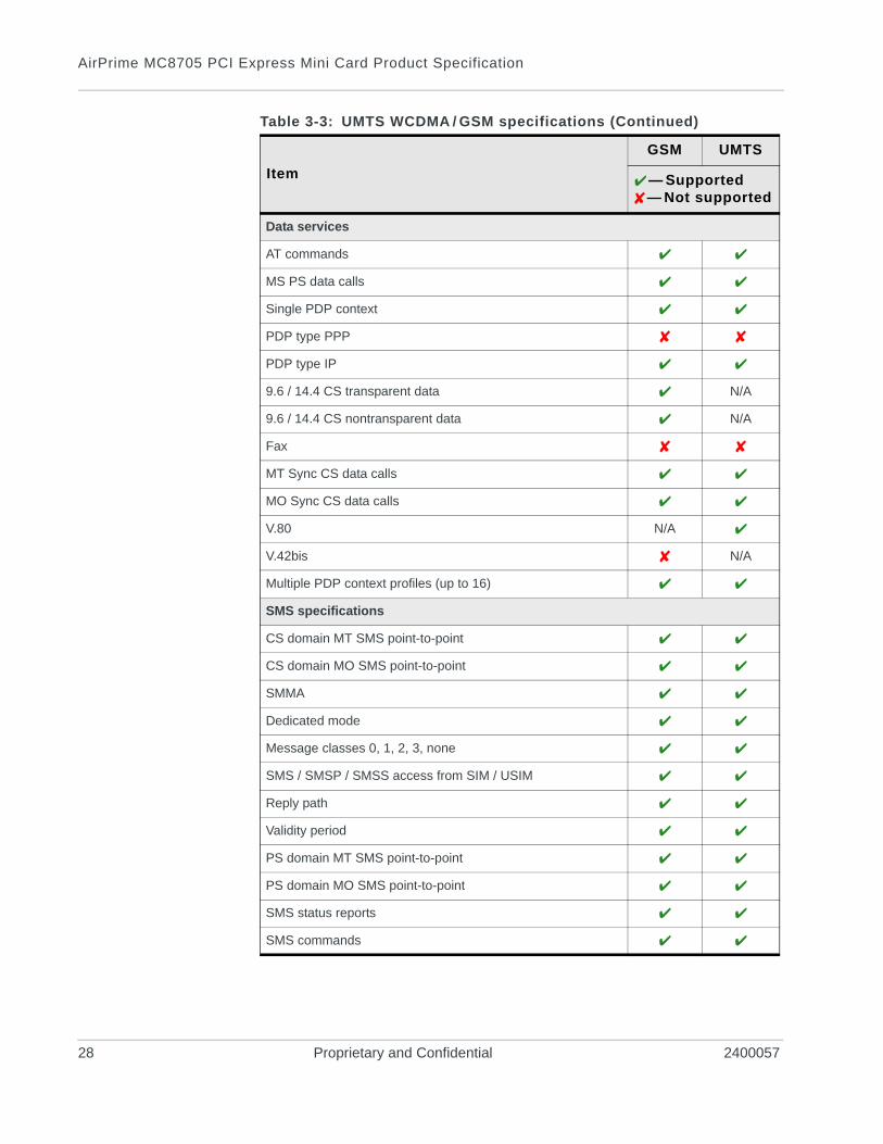
Data services
AT commands
MS PS data calls
Single PDP context
PDP type PPP
PDP type IP
9.6 / 14.4 CS transparent data N/A
9.6 / 14.4 CS nontransparent data N/A
Fax
MT Sync CS data calls
MO Sync CS data calls
V.80 N/A
V.42bis N/A
Multiple PDP context profiles (up to 16)
SMS specifications
CS domain MT SMS point-to-point
CS domain MO SMS point-to-point
SMMA
Dedicated mode
Message classes 0, 1, 2, 3, none
SMS / SMSP / SMSS access from SIM / USIM
Reply path
Validity period
PS domain MT SMS point-to-point
PS domain MO SMS point-to-point
SMS status reports
SMS commands
Table 3-3: UMTS WCDMA / GSM specifications (Continued)
Item
GSM UMTS
— Supported— Not supported
28 Proprietary and Confidential 2400057
Standards Compliance
UMTS RABs supported
The MC8705 supports the majority of the radio access bearers specified in 3GPP TS 34.108. If you require a detailed list, contact Sierra Wireless.
Short Message Service (SMS)
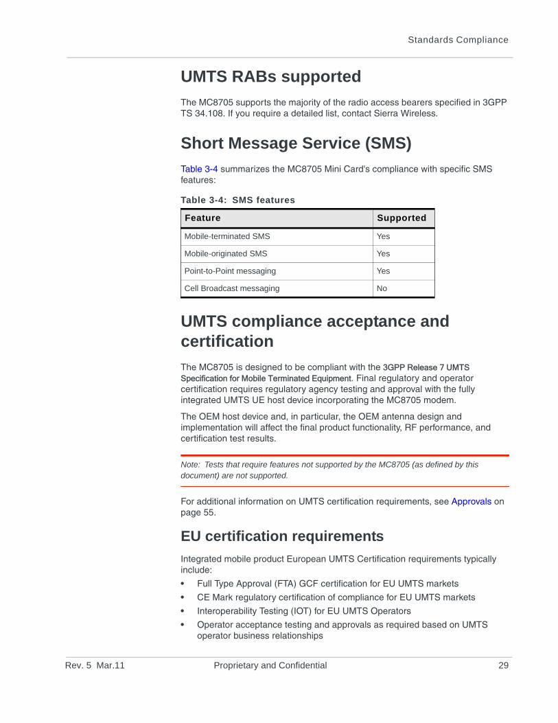
Table 3-4 summarizes the MC8705 Mini Card's compliance with specific SMS features:
UMTS compliance acceptance and certification
The MC8705 is designed to be compliant with the 3GPP Release 7 UMTS Specification for Mobile Terminated Equipment. Final regulatory and operator certification requires regulatory agency testing and approval with the fully integrated UMTS UE host device incorporating the MC8705 modem.
The OEM host device and, in particular, the OEM antenna design and implementation will affect the final product functionality, RF performance, and certification test results.
Note: Tests that require features not supported by the MC8705 (as defined by this document) are not supported.
For additional information on UMTS certification requirements, see Approvals on page 55.
EU certification requirements
Integrated mobile product European UMTS Certification requirements typically include:
• Full Type Approval (FTA) GCF certification for EU UMTS markets
• CE Mark regulatory certification of compliance for EU UMTS markets
• Interoperability Testing (IOT) for EU UMTS Operators
• Operator acceptance testing and approvals as required based on UMTS operator business relationships
Table 3-4: SMS features
Feature Supported
Mobile-terminated SMS Yes
Mobile-originated SMS Yes
Point-to-Point messaging Yes
Cell Broadcast messaging No
Rev. 5 Mar.11 Proprietary and Confidential 29
AirPrime MC8705 PCI Express Mini Card Product Specification
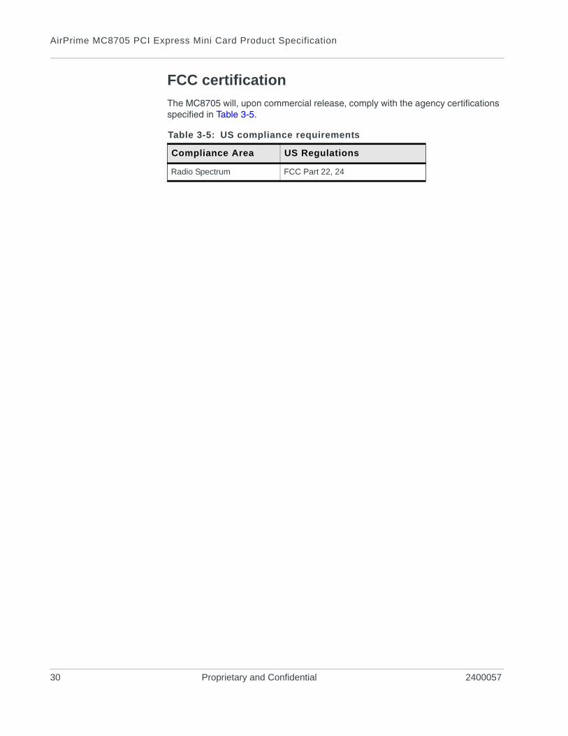
FCC certification
The MC8705 will, upon commercial release, comply with the agency certifications specified in Table 3-5.
Table 3-5: US compliance requirements
Compliance Area US Regulations
Radio Spectrum FCC Part 22, 24
30 Proprietary and Confidential 2400057
Rev. 5 Ma
4
AntennFrontEnd
Modul
Mainantenn
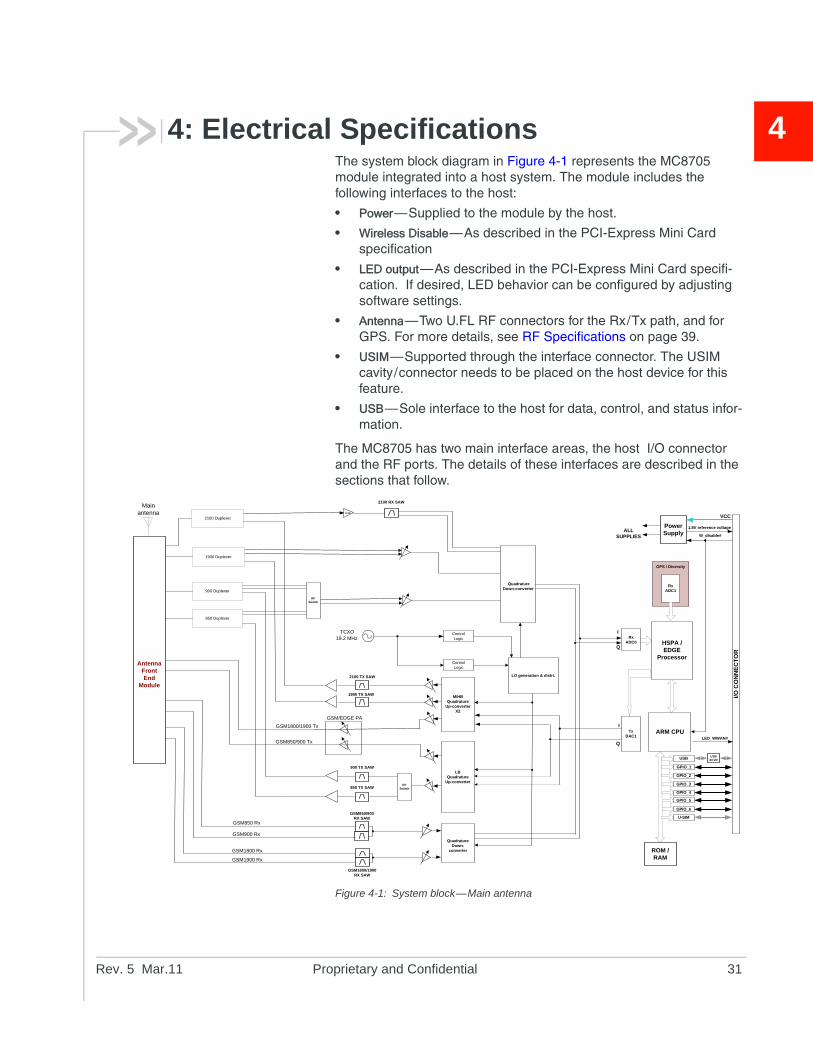
4: Electrical SpecificationsThe system block diagram in Figure 4-1 represents the MC8705 module integrated into a host system. The module includes the following interfaces to the host:
• Power—Supplied to the module by the host.
• Wireless Disable—As described in the PCI-Express Mini Card specification
• LED output—As described in the PCI-Express Mini Card specifi-cation. If desired, LED behavior can be configured by adjusting software settings.
• Antenna—Two U.FL RF connectors for the Rx/Tx path, and for GPS. For more details, see RF Specifications on page 39.
• USIM—Supported through the interface connector. The USIM cavity/connector needs to be placed on the host device for this feature.
• USB—Sole interface to the host for data, control, and status infor-mation.
The MC8705 has two main interface areas, the host I/O connector and the RF ports. The details of these interfaces are described in the sections that follow.
Figure 4-1: System block—Main antenna
Common toMain and
GPS / Diversity
GPS / Diversity
a
e
HSPA / EDGE
Processor
I/O C
ON
NE
CT
OR
ROM / RAM
SBI
ALL SUPPLIES
VCC
ARM CPU
Power Supply
TxDAC1
Q
I
W_disable#
LED_WWAN#
QuadratureDown-
converter
M/HBQuadrature
Up-converterX2
LO generation & distri.
GSM850/900 RX SAW
GSM1800/1900 RX SAW
2100 Duplexer
900 Duplexer
850 Duplexer
19.2 MHz
GSM900 Rx
GSM1800 Rx
GSM1900 Rx
TCXORx
ADC0
Q
I
ControlLogic
ControlLogic
Quadrature Down-converter
U-SIM
USB
GPIO_2
GPIO_3
GPIO_4
GPIO_5
GPIO_6
GPIO_1
1.8V reference voltage
USBXCVR
a
Rx ADC1
1900 Duplexer
GSM850/900 Tx
GSM1800/1900 Tx
GSM/EDGE PA
LBQuadrature
Up-converter
900 TX SAW
GSM850 Rx
850 TX SAW
LNA
2100 RX SAW
1900 TX SAW
2100 TX SAW
RF Switch
RF Switch
r.11 Proprietary and Confidential 31
AirPrime MC8705 PCI Express Mini Card Product Specification
P
1
2
3
4
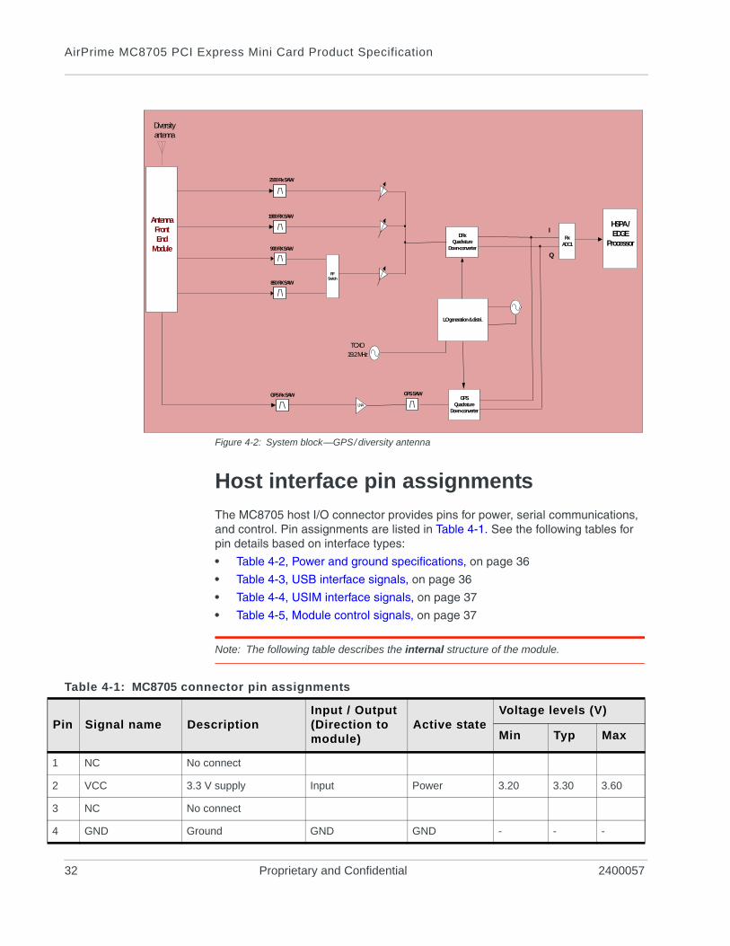
Figure 4-2: System block—GPS/ diversity antenna
Host interface pin assignments
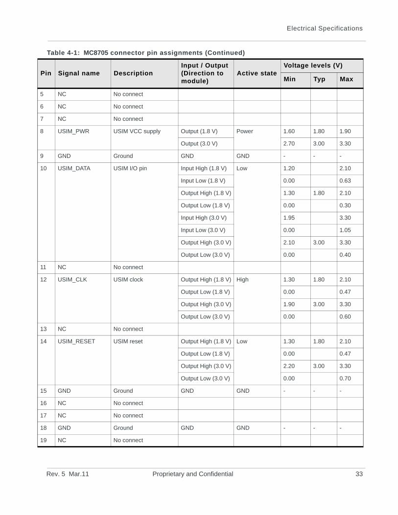
The MC8705 host I/O connector provides pins for power, serial communications, and control. Pin assignments are listed in Table 4-1. See the following tables for pin details based on interface types:
• Table 4-2, Power and ground specifications, on page 36
• Table 4-3, USB interface signals, on page 36
• Table 4-4, USIM interface signals, on page 37
• Table 4-5, Module control signals, on page 37
Note: The following table describes the internal structure of the module.
HSPA / EDGE
Processor
Q
I
LO generation & distri.
19.2 MHzTCXO
Rx ADC1
2100 Rx SAW
1900 RX SAW
GPS Rx SAW
DRxQuadrature
Down-converter
GPSQuadrature
Down-converter
Diversityantenna
GPS SAW
900 RX SAW
850 RX SAW
Antenna FrontEnd
Module
LNA
RF Switch
Table 4-1: MC8705 connector pin assignments
in Signal name DescriptionInput / Output (Direction to module)
Active stateVoltage levels (V)
Min Typ Max
NC No connect
VCC 3.3 V supply Input Power 3.20 3.30 3.60
NC No connect
GND Ground GND GND - - -
32 Proprietary and Confidential 2400057
Electrical Specifications
5
6
7
8
9
1
1
1
1
1
1
1
1
1
1
P
NC No connect
NC No connect
NC No connect
USIM_PWR USIM VCC supply Output (1.8 V) Power 1.60 1.80 1.90
Output (3.0 V) 2.70 3.00 3.30
GND Ground GND GND - - -
0 USIM_DATA USIM I/O pin Input High (1.8 V) Low 1.20 2.10
Input Low (1.8 V) 0.00 0.63
Output High (1.8 V) 1.30 1.80 2.10
Output Low (1.8 V) 0.00 0.30
Input High (3.0 V) 1.95 3.30
Input Low (3.0 V) 0.00 1.05
Output High (3.0 V) 2.10 3.00 3.30
Output Low (3.0 V) 0.00 0.40
1 NC No connect
2 USIM_CLK USIM clock Output High (1.8 V) High 1.30 1.80 2.10
Output Low (1.8 V) 0.00 0.47
Output High (3.0 V) 1.90 3.00 3.30
Output Low (3.0 V) 0.00 0.60
3 NC No connect
4 USIM_RESET USIM reset Output High (1.8 V) Low 1.30 1.80 2.10
Output Low (1.8 V) 0.00 0.47
Output High (3.0 V) 2.20 3.00 3.30
Output Low (3.0 V) 0.00 0.70
5 GND Ground GND GND - - -
6 NC No connect
7 NC No connect
8 GND Ground GND GND - - -
9 NC No connect
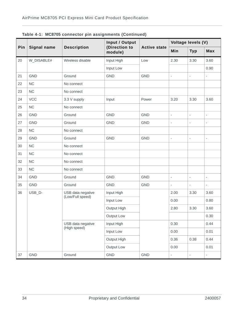
Table 4-1: MC8705 connector pin assignments (Continued)
in Signal name DescriptionInput / Output (Direction to module)
Active stateVoltage levels (V)
Min Typ Max
Rev. 5 Mar.11 Proprietary and Confidential 33
AirPrime MC8705 PCI Express Mini Card Product Specification
2
2
2
2
2
2
2
2
2
2
3
3
3
3
3
3
3
3
P
0 W_DISABLE# Wireless disable Input High Low 2.30 3.30 3.60
Input Low 0.90
1 GND Ground GND GND - - -
2 NC No connect
3 NC No connect
4 VCC 3.3 V supply Input Power 3.20 3.30 3.60
5 NC No connect
6 GND Ground GND GND - - -
7 GND Ground GND GND - - -
8 NC No connect
9 GND Ground GND GND - - -
0 NC No connect
1 NC No connect
2 NC No connect
3 NC No connect
4 GND Ground GND GND - - -
5 GND Ground GND GND - - -
6 USB_D- USB data negative(Low/Full speed)
Input High 2.00 3.30 3.60
Input Low 0.00 0.80
Output High 2.80 3.30 3.60
Output Low 0.30
USB data negative(High speed)
Input High 0.30 0.44
Input Low 0.00 0.01
Output High 0.36 0.38 0.44
Output Low 0.00 0.01
7 GND Ground GND GND - - -
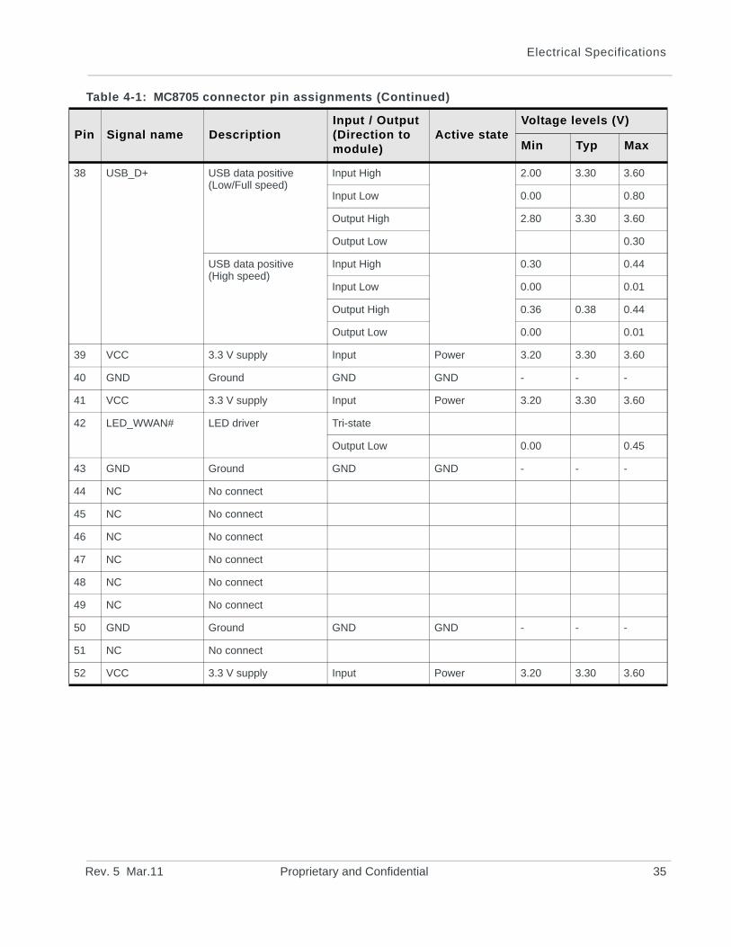
Table 4-1: MC8705 connector pin assignments (Continued)
in Signal name DescriptionInput / Output (Direction to module)
Active stateVoltage levels (V)
Min Typ Max
34 Proprietary and Confidential 2400057
Electrical Specifications
3
3
4
4
4
4
4
4
4
4
4
4
5
5
5
P
8 USB_D+ USB data positive(Low/Full speed)
Input High 2.00 3.30 3.60
Input Low 0.00 0.80
Output High 2.80 3.30 3.60
Output Low 0.30
USB data positive(High speed)
Input High 0.30 0.44
Input Low 0.00 0.01
Output High 0.36 0.38 0.44
Output Low 0.00 0.01
9 VCC 3.3 V supply Input Power 3.20 3.30 3.60
0 GND Ground GND GND - - -
1 VCC 3.3 V supply Input Power 3.20 3.30 3.60
2 LED_WWAN# LED driver Tri-state
Output Low 0.00 0.45
3 GND Ground GND GND - - -
4 NC No connect
5 NC No connect
6 NC No connect
7 NC No connect
8 NC No connect
9 NC No connect
0 GND Ground GND GND - - -
1 NC No connect
2 VCC 3.3 V supply Input Power 3.20 3.30 3.60
Table 4-1: MC8705 connector pin assignments (Continued)
in Signal name DescriptionInput / Output (Direction to module)
Active stateVoltage levels (V)
Min Typ Max
Rev. 5 Mar.11 Proprietary and Confidential 35
AirPrime MC8705 PCI Express Mini Card Product Specification
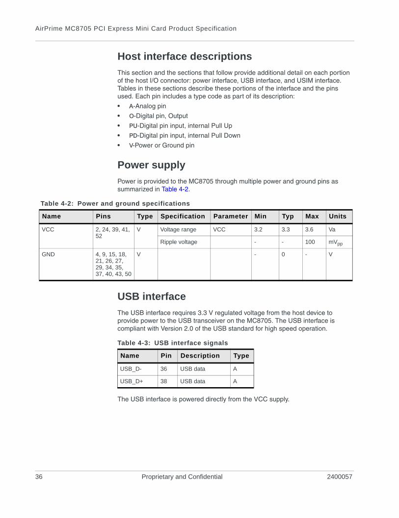
Host interface descriptions
This section and the sections that follow provide additional detail on each portion of the host I/O connector: power interface, USB interface, and USIM interface. Tables in these sections describe these portions of the interface and the pins used. Each pin includes a type code as part of its description:
• A-Analog pin
• O-Digital pin, Output
• PU-Digital pin input, internal Pull Up
• PD-Digital pin input, internal Pull Down
• V-Power or Ground pin
Power supply
Power is provided to the MC8705 through multiple power and ground pins as summarized in Table 4-2.
USB interface
The USB interface requires 3.3 V regulated voltage from the host device to provide power to the USB transceiver on the MC8705. The USB interface is compliant with Version 2.0 of the USB standard for high speed operation.
The USB interface is powered directly from the VCC supply.
Table 4-2: Power and ground specifications
Name Pins Type Specification Parameter Min Typ Max Units
VCC 2, 24, 39, 41, 52
V Voltage range VCC 3.2 3.3 3.6 Va
Ripple voltage - - 100 mVpp
GND 4, 9, 15, 18, 21, 26, 27, 29, 34, 35, 37, 40, 43, 50
V - 0 - V
Table 4-3: USB interface signals
Name Pin Description Type
USB_D- 36 USB data A
USB_D+ 38 USB data A
36 Proprietary and Confidential 2400057
Electrical Specifications
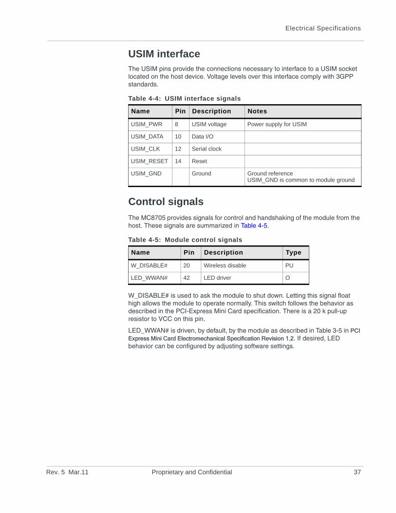
USIM interfaceThe USIM pins provide the connections necessary to interface to a USIM socket located on the host device. Voltage levels over this interface comply with 3GPP standards.
Control signals
The MC8705 provides signals for control and handshaking of the module from the host. These signals are summarized in Table 4-5.
W_DISABLE# is used to ask the module to shut down. Letting this signal float high allows the module to operate normally. This switch follows the behavior as described in the PCI-Express Mini Card specification. There is a 20 k pull-up resistor to VCC on this pin.
LED_WWAN# is driven, by default, by the module as described in Table 3-5 in PCI Express Mini Card Electromechanical Specification Revision 1.2. If desired, LED behavior can be configured by adjusting software settings.
Table 4-4: USIM interface signals
Name Pin Description Notes
USIM_PWR 8 USIM voltage Power supply for USIM
USIM_DATA 10 Data I/O
USIM_CLK 12 Serial clock
USIM_RESET 14 Reset
USIM_GND Ground Ground referenceUSIM_GND is common to module ground
Table 4-5: Module control signals
Name Pin Description Type
W_DISABLE# 20 Wireless disable PU
LED_WWAN# 42 LED driver O
Rev. 5 Mar.11 Proprietary and Confidential 37

AirPrime MC8705 PCI Express Mini Card Product Specification
38 Proprietary and Confidential 2400057
Rev. 5 Ma
5
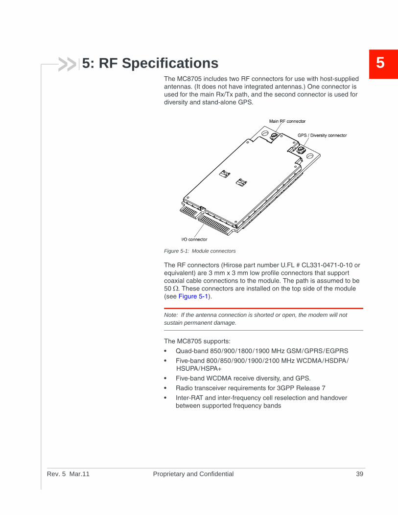
5: RF SpecificationsThe MC8705 includes two RF connectors for use with host-supplied antennas. (It does not have integrated antennas.) One connector is used for the main Rx/Tx path, and the second connector is used for diversity and stand-alone GPS.Figure 5-1: Module connectors
The RF connectors (Hirose part number U.FL # CL331-0471-0-10 or equivalent) are 3 mm x 3 mm low profile connectors that support coaxial cable connections to the module. The path is assumed to be 50 . These connectors are installed on the top side of the module (see Figure 5-1).
Note: If the antenna connection is shorted or open, the modem will not sustain permanent damage.
The MC8705 supports:
• Quad-band 850/900/1800/1900 MHz GSM/GPRS/EGPRS
• Five-band 800/850/900/1900/2100 MHz WCDMA/HSDPA/HSUPA/HSPA+
• Five-band WCDMA receive diversity, and GPS.
• Radio transceiver requirements for 3GPP Release 7
• Inter-RAT and inter-frequency cell reselection and handover between supported frequency bands
r.11 Proprietary and Confidential 39
AirPrime MC8705 PCI Express Mini Card Product Specification
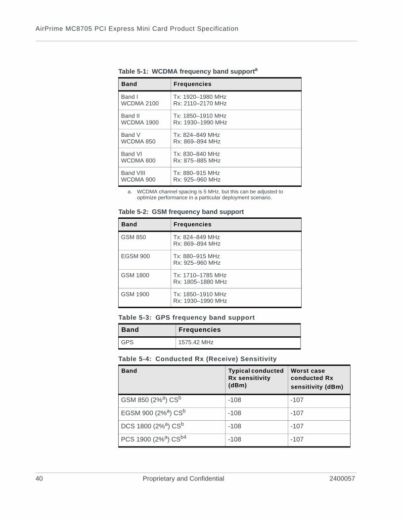
Table 5-1: WCDMA frequency band supporta
a. WCDMA channel spacing is 5 MHz, but this can be adjusted to optimize performance in a particular deployment scenario.
Band Frequencies
Band IWCDMA 2100
Tx: 1920–1980 MHzRx: 2110–2170 MHz
Band IIWCDMA 1900
Tx: 1850–1910 MHzRx: 1930–1990 MHz
Band VWCDMA 850
Tx: 824–849 MHzRx: 869–894 MHz
Band VIWCDMA 800
Tx: 830–840 MHzRx: 875–885 MHz
Band VIIIWCDMA 900
Tx: 880–915 MHzRx: 925–960 MHz
Table 5-2: GSM frequency band support
Band Frequencies
GSM 850 Tx: 824–849 MHzRx: 869–894 MHz
EGSM 900 Tx: 880–915 MHzRx: 925–960 MHz
GSM 1800 Tx: 1710–1785 MHzRx: 1805–1880 MHz
GSM 1900 Tx: 1850–1910 MHzRx: 1930–1990 MHz
Table 5-3: GPS frequency band support
Band Frequencies
GPS 1575.42 MHz
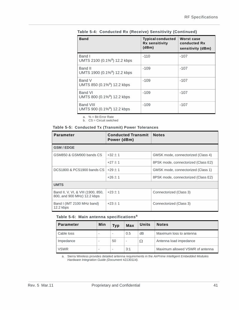
Table 5-4: Conducted Rx (Receive) Sensitivity
Band Typical conducted Rx sensitivity (dBm)
Worst case conducted Rx
sensitivity (dBm)
GSM 850 (2%a) CSb -108 -107
EGSM 900 (2%a) CSb -108 -107
DCS 1800 (2%a) CSb -108 -107
PCS 1900 (2%a) CSb4 -108 -107
40 Proprietary and Confidential 2400057
RF Specifications
Band IUMTS 2100 (0.1%a) 12.2 kbps
-110 -107
Band IIUMTS 1900 (0.1%a) 12.2 kbps
-109 -107
Band VUMTS 850 (0.1%a) 12.2 kbps
-109 -107
Band VIUMTS 800 (0.1%a) 12.2 kbps
-109 -107
Band VIIIUMTS 900 (0.1%a) 12.2 kbps
-109 -107
a. % = Bit Error Rateb. CS = Circuit switched
Table 5-4: Conducted Rx (Receive) Sensitivity (Continued)
Band Typical conducted Rx sensitivity (dBm)
Worst case conducted Rx
sensitivity (dBm)
Table 5-5: Conducted Tx (Transmit) Power Tolerances
Parameter Conducted Transmit Power (dBm)
Notes
GSM / EDGE
GSM850 & GSM900 bands CS +32 1 GMSK mode, connectorized (Class 4)
+27 1 8PSK mode, connectorized (Class E2)
DCS1800 & PCS1900 bands CS +29 1 GMSK mode, connectorized (Class 1)
+26 1 8PSK mode, connectorized (Class E2)
UMTS
Band II, V, VI, & VIII (1900, 850, 800, and 900 MHz) 12.2 kbps
+23 1 Connectorized (Class 3)
Band I (IMT 2100 MHz band) 12.2 kbps
+23 1 Connectorized (Class 3)
Table 5-6: Main antenna specificationsa
Parameter Min Typ Max Units Notes
Cable loss - - 0.5 dB Maximum loss to antenna
Impedance - 50 - Antenna load impedance
VSWR - - 3:1 Maximum allowed VSWR of antenna
a. Sierra Wireless provides detailed antenna requirements in the AirPrime Intelligent Embedded Modules Hardware Integration Guide (Document #2130114).
Rev. 5 Mar.11 Proprietary and Confidential 41
AirPrime MC8705 PCI Express Mini Card Product Specification
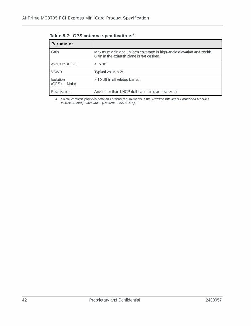
Table 5-7: GPS antenna specificationsa
Parameter
Gain Maximum gain and uniform coverage in high-angle elevation and zenith.Gain in the azimuth plane is not desired.
Average 3D gain > -5 dBi
VSWR Typical value < 2:1
Isolation(GPS Main)
> 10 dB in all related bands
Polarization Any, other than LHCP (left-hand circular polarized)
a. Sierra Wireless provides detailed antenna requirements in the AirPrime Intelligent Embedded Modules Hardware Integration Guide (Document #2130114).
42 Proprietary and Confidential 2400057
Rev. 5 Ma
6
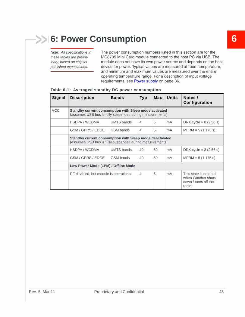
6: Power ConsumptionNote: All specifications in these tables are prelim-inary, based on chipset published expectations.The power consumption numbers listed in this section are for the MC8705 Mini Card module connected to the host PC via USB. The module does not have its own power source and depends on the host device for power. Typical values are measured at room temperature, and minimum and maximum values are measured over the entire operating temperature range. For a description of input voltage requirements, see Power supply on page 36.
Table 6-1: Averaged standby DC power consumption
Signal Description Bands Typ Max Units Notes / Configuration
VCC Standby current consumption with Sleep mode activated(assumes USB bus is fully suspended during measurements)
HSDPA / WCDMA UMTS bands 4 5 mA DRX cycle = 8 (2.56 s)
GSM / GPRS / EDGE GSM bands 4 5 mA MFRM = 5 (1.175 s)
Standby current consumption with Sleep mode deactivated(assumes USB bus is fully suspended during measurements)
HSDPA / WCDMA UMTS bands 40 50 mA DRX cycle = 8 (2.56 s)
GSM / GPRS / EDGE GSM bands 40 50 mA MFRM = 5 (1.175 s)
Low Power Mode (LPM) / Offline Mode
RF disabled, but module is operational 4 5 mA This state is entered when Watcher shuts down / turns off the radio.
r.11 Proprietary and Confidential 43
AirPrime MC8705 PCI Express Mini Card Product Specification
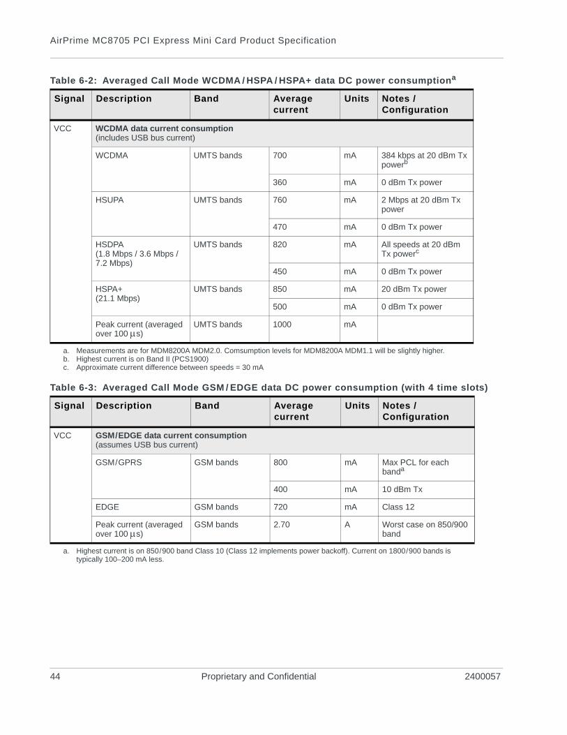
Table 6-2: Averaged Call Mode WCDMA / HSPA / HSPA+ data DC power consumptiona
Signal Description Band Average current
Units Notes / Configuration
VCC WCDMA data current consumption(includes USB bus current)
WCDMA UMTS bands 700 mA 384 kbps at 20 dBm Tx powerb
360 mA 0 dBm Tx power
HSUPA UMTS bands 760 mA 2 Mbps at 20 dBm Tx power
470 mA 0 dBm Tx power
HSDPA(1.8 Mbps / 3.6 Mbps / 7.2 Mbps)
UMTS bands 820 mA All speeds at 20 dBm Tx powerc
450 mA 0 dBm Tx power
HSPA+(21.1 Mbps)
UMTS bands 850 mA 20 dBm Tx power
500 mA 0 dBm Tx power
Peak current (averaged over 100 s)
UMTS bands 1000 mA
a. Measurements are for MDM8200A MDM2.0. Comsumption levels for MDM8200A MDM1.1 will be slightly higher.b. Highest current is on Band II (PCS1900)c. Approximate current difference between speeds = 30 mA
Table 6-3: Averaged Call Mode GSM / EDGE data DC power consumption (with 4 time slots)
Signal Description Band Average current
Units Notes / Configuration
VCC GSM/EDGE data current consumption(assumes USB bus current)
GSM/GPRS GSM bands 800 mA Max PCL for each banda
400 mA 10 dBm Tx
EDGE GSM bands 720 mA Class 12
Peak current (averaged over 100 s)
GSM bands 2.70 A Worst case on 850/900 band
a. Highest current is on 850/900 band Class 10 (Class 12 implements power backoff). Current on 1800/900 bands is typically 100–200 mA less.
44 Proprietary and Confidential 2400057
Power Consumption
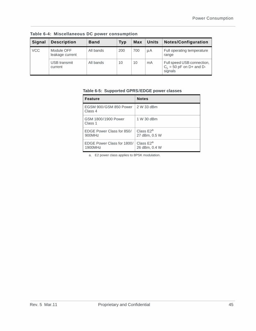
Table 6-4: Miscellaneous DC power consumption
Signal Description Band Typ Max Units Notes/Configuration
VCC Module OFF leakage current
All bands 200 700 A Full operating temperature range
USB transmit current
All bands 10 10 mA Full speed USB connection, CL = 50 pF on D+ and D- signals
Table 6-5: Supported GPRS/EDGE power classes
Feature Notes
EGSM 900/GSM 850 Power Class 4
2 W 33 dBm
GSM 1800/1900 Power Class 1
1 W 30 dBm
EDGE Power Class for 850/900MHz
Class E2a
27 dBm, 0.5 W
a. E2 power class applies to 8PSK modulation.
EDGE Power Class for 1800/1900MHz
Class E2a
26 dBm, 0.4 W
Rev. 5 Mar.11 Proprietary and Confidential 45

AirPrime MC8705 PCI Express Mini Card Product Specification
46 Proprietary and Confidential 2400057
Rev. 5 Ma
7
7: GPSNote: The specifications in this section are subject to change without notice. Actual GPS functionality is dependent on the firmware version and module config-uration.The MC8705 Mini Card module includes a built-in GPS module that provides the following features:
• Standalone GPS· Leading standalone/autonomous GPS performance· -155 dBm sensitivity· -156 dBm tracking sensitivity· < 1 minute average cold start TTFF (Time To First Fix) in open
sky· < 3 second average super hot TTFF in open sky· < 10 m accuracy in open sky
Note: For optimum performance, the modem should be registered on the GSM/UMTS network, but does not need to be on an active data call.
• gpsOneXTRA™· Enables enhanced standalone GPS operation by downloading
< 40 kB file from a server on the Internet· Performance closer to UE-based operation than traditional
standalone GPS operation· Best if downloaded once every 1–2 days, but valid for up to 7
days with some accuracy degradation
• A-GPS features· Leading A-GPS performance· Exceeds 3GPP RAN 4 AGPS performance specification· -155 dBm sensitivity· -156 dBm tracking sensitivity· < 5 second average cold start TTFF in open sky (UE-based)· < 3 second average super hot TTFF in open sky· < 10 m accuracy in open sky· UMTS Control Plane (CP)—UE-assisted and UE-based· GSM Control Plane (CP)—UE-assisted and UE-based· OMA SUPL 1.0 User Plane (UP)—UE-assisted and UE-based
• Enhanced Navigation 2.0 feature· Provides leading performance in car and walking navigation
modes as well as accuracy while stationary· Airline/Game/Offline mode· GPS capability is available while phone is offline
• Application types· Supports NMEA (supported sentences: GGA, GSA, GSV,
RMC, VTG)
r.11 Proprietary and Confidential 47
AirPrime MC8705 PCI Express Mini Card Product Specification
48 Proprietary and Confidential 2400057
Rev. 5 Ma
8
8: Software InterfacePhysical interface options
The MC8705 module communicates with the host via the USB (Universal Serial Bus) physical interface, using a non-MUX (non-composite) USB architecture.
The non-MUX architecture supports multiple pairs of endpoints, each with a unique supported service (Control, AT/PPP, HIP). Documentation outlining the design requirements for non_MUX is available; see the Mini Card / AirCard / Compass USB Driver Developer’s Guide for details.
USB interface details
USB high/full speed throughput performance
This device has been designed to achieve optimal performance and maximum throughput using USB high speed mode. Although the device may operate with a full speed host, throughput performance will be on an “as is” basis and needs to be characterized by the OEM. Note that throughput will be reduced and may vary significantly based on packet size, host interface, and firmware revision. Sierra Wireless does not recommend using this device in USB full speed mode.
USB support for Direct IP
USB high speed mode must be used with the Direct IP interface (USB full speed mode is not supported).
Support tools
The MC8705 is compatible with the following support tools from Sierra Wireless and authorized third parties:
• Sierra Wireless Watcher
• QXDM from Qualcomm
r.11 Proprietary and Confidential 49
AirPrime MC8705 PCI Express Mini Card Product Specification
Other features
Customization
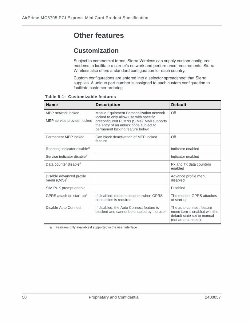
Subject to commercial terms, Sierra Wireless can supply custom-configured modems to facilitate a carrier's network and performance requirements. Sierra Wireless also offers a standard configuration for each country.
Custom configurations are entered into a selector spreadsheet that Sierra supplies. A unique part number is assigned to each custom configuration to facilitate customer ordering.
Table 8-1: Customizable features
Name Description Default
MEP network locked Mobile Equipment Personalization network locked to only allow use with specific preconfigured PLMNs (SIMs). MMI supports the entry of an unlock code subject to permanent locking feature below.
Off
MEP service provider locked
Permanent MEP locked Can block deactivation of MEP locked feature
Off
Roaming indicator disablea Indicator enabled
Service indicator disablea Indicator enabled
Data counter disablea Rx and Tx data counters enabled
Disable advanced profile menu (QoS)a
Advance profile menu disabled
SIM PUK prompt enable Disabled
GPRS attach on start-upa If disabled, modem attaches when GPRS connection is required.
The modem GPRS attaches at start-up.
Disable Auto Connect If disabled, the Auto Connect feature is blocked and cannot be enabled by the user.
The auto-connect feature menu item is enabled with the default state set to manual (not auto-connect).
a. Features only available if supported in the user interface
50 Proprietary and Confidential 2400057
Rev. 5 Ma
9
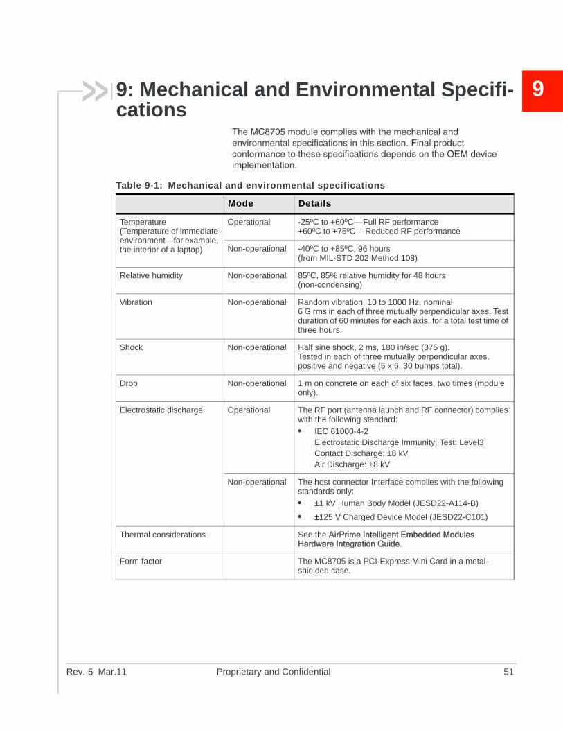
9: Mechanical and Environmental Specifi-cationsThe MC8705 module complies with the mechanical and environmental specifications in this section. Final product conformance to these specifications depends on the OEM device implementation.
Table 9-1: Mechanical and environmental specifications
Mode Details
Temperature(Temperature of immediate environment—for example, the interior of a laptop)
Operational -25ºC to +60ºC—Full RF performance+60ºC to +75ºC—Reduced RF performance
Non-operational -40ºC to +85ºC, 96 hours(from MIL-STD 202 Method 108)
Relative humidity Non-operational 85ºC, 85% relative humidity for 48 hours (non-condensing)
Vibration Non-operational Random vibration, 10 to 1000 Hz, nominal6 G rms in each of three mutually perpendicular axes. Test duration of 60 minutes for each axis, for a total test time of three hours.
Shock Non-operational Half sine shock, 2 ms, 180 in/sec (375 g).Tested in each of three mutually perpendicular axes, positive and negative (5 x 6, 30 bumps total).
Drop Non-operational 1 m on concrete on each of six faces, two times (module only).
Electrostatic discharge Operational The RF port (antenna launch and RF connector) complies with the following standard:
• IEC 61000-4-2Electrostatic Discharge Immunity: Test: Level3Contact Discharge: ±6 kVAir Discharge: ±8 kV
Non-operational The host connector Interface complies with the following standards only:
• ±1 kV Human Body Model (JESD22-A114-B)
• ±125 V Charged Device Model (JESD22-C101)
Thermal considerations See the AirPrime Intelligent Embedded Modules Hardware Integration Guide.
Form factor The MC8705 is a PCI-Express Mini Card in a metal-shielded case.
r.11 Proprietary and Confidential 51
AirPrime MC8705 PCI Express Mini Card Product Specification
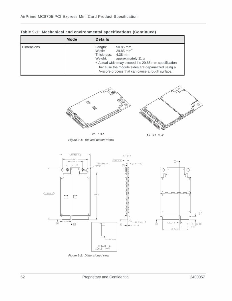
Figure 9-1: Top and bottom views
Figure 9-2: Dimensioned view
Dimensions Length: 50.85 mm Width: 29.85 mm
Thickness: 4.38 mmWeight: approximately 11 g Actual width may exceed the 29.85 mm specification
because the module sides are depanelized using a V-score process that can cause a rough surface.
Table 9-1: Mechanical and environmental specifications (Continued)
Mode Details
52 Proprietary and Confidential 2400057
Mechanical and Environmental Specifications
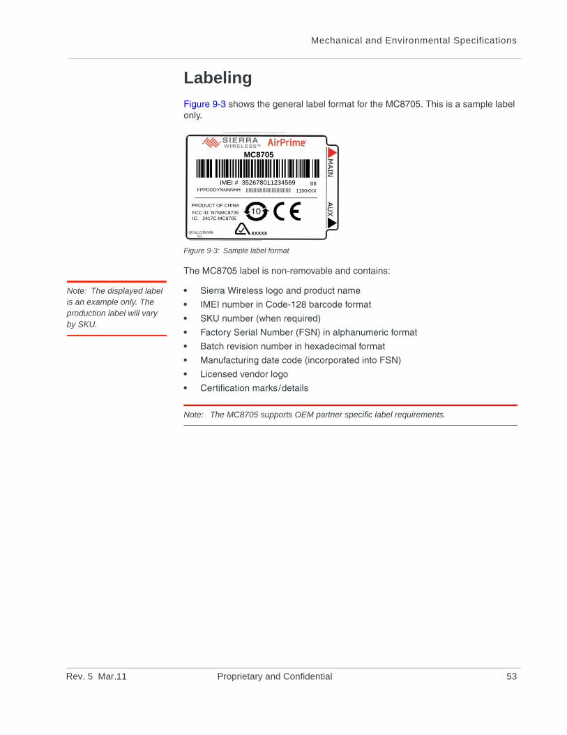
Labeling
Figure 9-3 shows the general label format for the MC8705. This is a sample label only.
Figure 9-3: Sample label format
The MC8705 label is non-removable and contains:
Note: The displayed label is an example only. The production label will vary by SKU.
• Sierra Wireless logo and product name
• IMEI number in Code-128 barcode format
• SKU number (when required)
• Factory Serial Number (FSN) in alphanumeric format
• Batch revision number in hexadecimal format
• Manufacturing date code (incorporated into FSN)
• Licensed vendor logo
• Certification marks/details
Note: The MC8705 supports OEM partner specific label requirements.
FCC ID: N7NMC8705IC: 2417C-MC8705
PRODUCT OF CHINA
1100XXXFPPDDDYNNNNHH |||||||||||||||||||||||||||||||||||
IMEI # 352678011234569
MC8705
BB
XXXXX
Rev. 5 Mar.11 Proprietary and Confidential 53

AirPrime MC8705 PCI Express Mini Card Product Specification
54 Proprietary and Confidential 2400057
Rev. 5 Ma
10
10: ApprovalsUpon commercial release, the MC8705 will have approval from the following regulatory and type approval agencies:• North America: Federal Communications Commission (FCC) and Industry Canada (IC)
Upon commercial release, the following industry type approvals may be obtained upon customer request:
• North and Latin America operators/carriersPTCRB approval per NAPRD03 requirement
Additional testing and certification may be required for the end product with an embedded MC8705 modem and are the responsibility of the OEM. Sierra Wireless offers professional services-based assistance to OEMs with the testing and certification process, if required.
r.11 Proprietary and Confidential 55

AirPrime MC8705 PCI Express Mini Card Product Specification
56 Proprietary and Confidential 2400057
Rev. 5 Ma
11
11: Additional RequirementsTesting assistance provided by Sierra Wireless
Extended AT commands have been implemented to assist with performing FTA GCF tests and portions of CE Mark tests requiring radio module access. These are documented in the AirCard/AirPrime UMTS Devices Supported AT Command Reference and AirPrime MC8xxx Embedded Modules Extended AT Command Reference.
The AirPrime Intelligent Embedded Modules Hardware Integration Guide includes a list of test houses familiar with Sierra Wireless products.
Sierra Wireless offers optional professional services based assistance to OEMs with regulatory approvals.
Integration requirements
When integrating the MC8705 PCI-Express Mini Card, the following items need to be addressed:
• Mounting—Effect on temperature, shock, and vibration perfor-mance
• Power supply—Impact on battery drain and possible RF inter-ference
• Antenna location and type—Impact on RF performance
• Regulatory approvals—As discussed in Approvals on page 55.
• Service provisioning—Manufacturing process
• Software—As discussed in Software Interface on page 49.
Sierra Wireless provides guidelines for successful MC8705 PCI-Express Mini Card integration with the document suite and offers integration support services as necessary.
IOT/Operator
Interoperability and Operator/Carrier testing of the finished system is the responsibility of the OEM. The test process will be determined with the chosen network operator(s) and will be dependent upon your business relationship with them, as well as the product's application and sales channel strategy.
Sierra Wireless offers assistance to OEMs with the testing process, if required.
r.11 Proprietary and Confidential 57

AirPrime MC8705 PCI Express Mini Card Product Specification
58 Proprietary and Confidential 2400057
Rev. 5 Ma
A
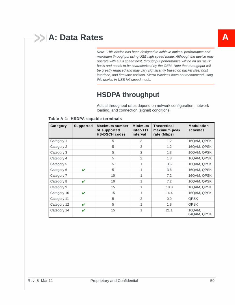
A: Data RatesNote: This device has been designed to achieve optimal performance and maximum throughput using USB high speed mode. Although the device may operate with a full speed host, throughput performance will be on an “as is” basis and needs to be characterized by the OEM. Note that throughput will be greatly reduced and may vary significantly based on packet size, host interface, and firmware revision. Sierra Wireless does not recommend using this device in USB full speed mode.
HSDPA throughput
Actual throughput rates depend on network configuration, network loading, and connection (signal) conditions.
Table A-1: HSDPA-capable terminals
Category Supported Maximum number of supported HS-DSCH codes
Minimum inter-TTI interval
Theoretical maximum peak rate (Mbps)
Modulation schemes
Category 1 5 3 1.2 16QAM, QPSK
Category 2 5 3 1.2 16QAM, QPSK
Category 3 5 2 1.8 16QAM, QPSK
Category 4 5 2 1.8 16QAM, QPSK
Category 5 5 1 3.6 16QAM, QPSK
Category 6 5 1 3.6 16QAM, QPSK
Category 7 10 1 7.2 16QAM, QPSK
Category 8 10 1 7.2 16QAM, QPSK
Category 9 15 1 10.0 16QAM, QPSK
Category 10 15 1 14.4 16QAM, QPSK
Category 11 5 2 0.9 QPSK
Category 12 5 1 1.8 QPSK
Category 14 15 1 21.1 16QAM, 64QAM, QPSK
r.11 Proprietary and Confidential 59
AirPrime MC8705 PCI Express Mini Card Product Specification
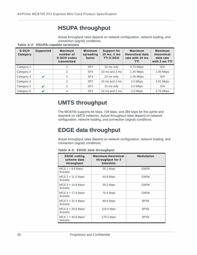
HSUPA throughput
Actual throughput rates depend on network configuration, network loading, and connection (signal) conditions.
UMTS throughput
The MC8705 supports 64 kbps, 128 kbps, and 384 kbps for the uplink and downlink on UMTS networks. Actual throughput rates depend on network configuration, network loading, and connection (signal) conditions.
EDGE data throughput
Actual throughput rates depend on network configuration, network loading, and connection (signal) conditions.
Table A-2: HSUPA-capable terminals
E-DCH Category
Supported Maximum number of
E-DCH codes transmitted
Minimum spreading
factor
Support for 10 ms; 2 msTTI E-DCH
Maximum theoretical data rate with 10 ms
TTI
Maximum theoretical data rate
with 2 ms TTI
Category 1 1 SF4 10 ms only 0.72 Mbps N/A
Category 2 2 SF4 10 ms and 2 ms 1.45 Mbps 1.45 Mbps
Category 3 2 SF4 10 ms only 1.45 Mbps N/A
Category 4 2 SF2 10 ms and 2 ms 2.0 Mbps 2.91 Mbps
Category 5 2 SF2 10 ms only 2.0 Mbps N/A
Category 6 4 SF2 10 ms and 2 ms 2.0 Mbps 5.76 Mbps
Table A-3: EDGE data throughput
EDGE coding scheme data throughput
Maximum theoretical throughput for 4
timeslots
Modulation
MCS 1 = 8.8 kbps/timeslot
35.2 kbps GMSK
MCS 2 = 11.2 kbps/timeslot
44.8 kbps GMSK
MCS 3 = 14.8 kbps/timeslot
59.2 kbps GMSK
MCS 4 = 17.6 kbps/timeslot
70.4 kbps GMSK
MCS 5 = 22.4 kbps/timeslot
89.6 kbps 8PSK
MCS 6 = 29.6 kbps/timeslot
118.4 kbps 8PSK
MCS 7 = 44.8 kbps/timeslot
179.2 kbps 8PSK
60 Proprietary and Confidential
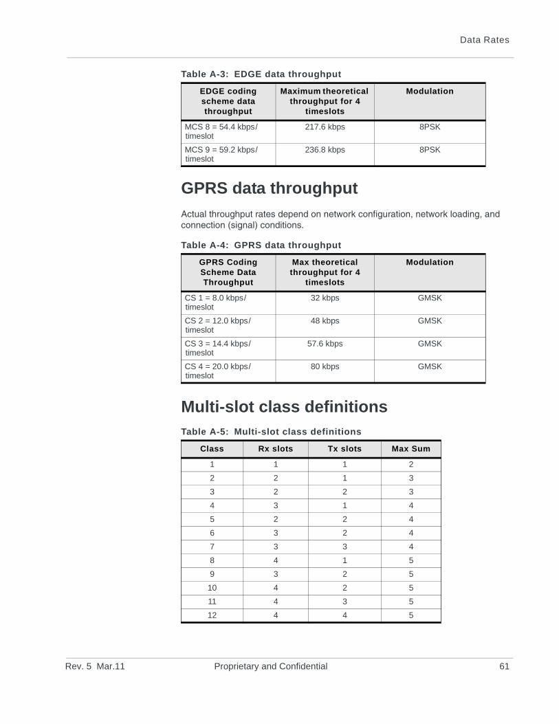
Data Rates
GPRS data throughput
Actual throughput rates depend on network configuration, network loading, and connection (signal) conditions.
Multi-slot class definitions
MCS 8 = 54.4 kbps/timeslot
217.6 kbps 8PSK
MCS 9 = 59.2 kbps/timeslot
236.8 kbps 8PSK
Table A-4: GPRS data throughput
GPRS Coding Scheme Data Throughput
Max theoretical throughput for 4
timeslots
Modulation
CS 1 = 8.0 kbps/timeslot
32 kbps GMSK
CS 2 = 12.0 kbps/timeslot
48 kbps GMSK
CS 3 = 14.4 kbps/timeslot
57.6 kbps GMSK
CS 4 = 20.0 kbps/timeslot
80 kbps GMSK
Table A-5: Multi-slot class definitions
Class Rx slots Tx slots Max Sum
1 1 1 2
2 2 1 3
3 2 2 3
4 3 1 4
5 2 2 4
6 3 2 4
7 3 3 4
8 4 1 5
9 3 2 5
10 4 2 5
11 4 3 5
12 4 4 5
Table A-3: EDGE data throughput
EDGE coding scheme data throughput
Maximum theoretical throughput for 4
timeslots
Modulation
Rev. 5 Mar.11 Proprietary and Confidential 61
AirPrime MC8705 PCI Express Mini Card Product Specification
62 Proprietary and Confidential
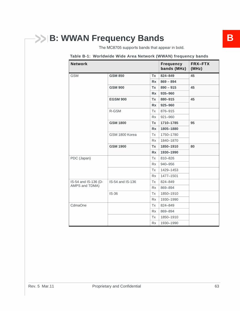
Rev. 5 Ma
B
B: WWAN Frequency BandsThe MC8705 supports bands that appear in bold.Table B-1: Worldwide Wide Area Network (WWAN) frequency bands
Network Frequency bands (MHz)
FRX–FTX (MHz)
GSM GSM 850 Tx 824–849 45
Rx 869 – 894
GSM 900 Tx 890 – 915 45
Rx 935–960
EGSM 900 Tx 880–915 45
Rx 925–960
R-GSM Tx 876–915
Rx 921–960
GSM 1800 Tx 1710–1785 95
Rx 1805–1880
GSM 1800 Korea Tx 1750–1780
Rx 1840–1870
GSM 1900 Tx 1850–1910 80
Rx 1930–1990
PDC (Japan) Tx 810–826
Rx 940–956
Tx 1429–1453
Rx 1477–1501
IS-54 and IS-136 (D-AMPS and TDMA)
IS-54 and IS-136 Tx 824–849
Rx 869–894
IS-36 Tx 1850–1910
Rx 1930–1990
CdmaOne Tx 824–849
Rx 869–894
Tx 1850–1910
Rx 1930–1990
r.11 Proprietary and Confidential 63
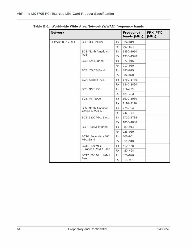
AirPrime MC8705 PCI Express Mini Card Product Specification
CDMA2000 1x RTT BC0: US Cellular Tx 824–849
Rx 869–894
BC1: North American PCS
Tx 1850–1910
Rx 1930–1990
BC2: TACS Band Tx 872–915
Rx 917–960
BC3: JTACS Band Tx 887–925
Rx 832–870
BC4: Korean PCS Tx 1750–1780
Rx 1840–1870
BC5: NMT 450 Tx 411–483
Rx 421–493
BC6: IMT 2000 Tx 1920–1980
Rx 2110–2170
BC7: North American 700 MHz Cellular
Tx 776–794
Rx 746–764
BC8: 1800 MHz Band Tx 1710–1785
Rx 1805–1880
BC9: 900 MHz Band Tx 880–914
Rx 925–959
BC10: Secondary 800 MHz Band
Tx 806–901
Rx 851–940
BC11: 400 MHz European PAMR Band
Tx 410–458
Rx 420–468
BC12: 800 MHz PAMR Band
Tx 870–876
Rx 915–921
Table B-1: Worldwide Wide Area Network (WWAN) frequency bands
Network Frequency bands (MHz)
FRX–FTX (MHz)
64 Proprietary and Confidential 2400057
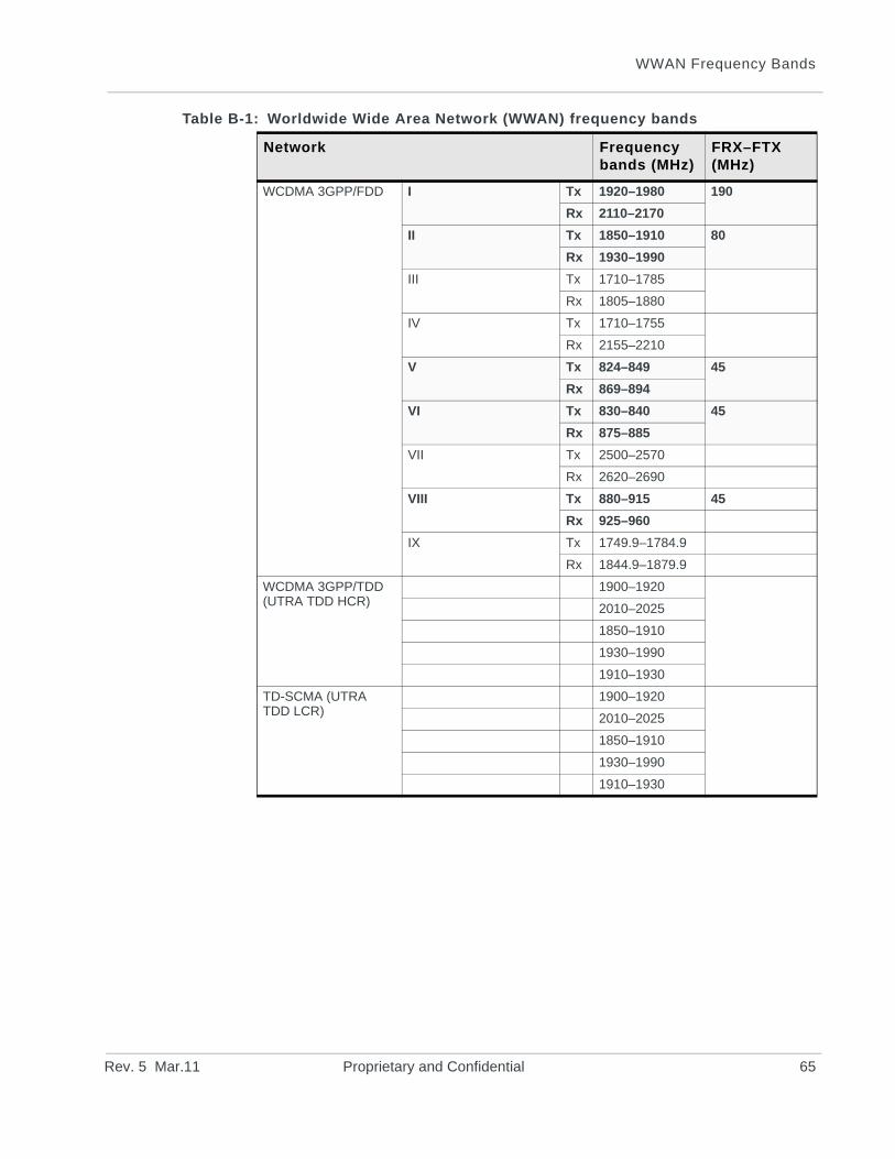
WWAN Frequency Bands
WCDMA 3GPP/FDD I Tx 1920–1980 190
Rx 2110–2170
II Tx 1850–1910 80
Rx 1930–1990
III Tx 1710–1785
Rx 1805–1880
IV Tx 1710–1755
Rx 2155–2210
V Tx 824–849 45
Rx 869–894
VI Tx 830–840 45
Rx 875–885
VII Tx 2500–2570
Rx 2620–2690
VIII Tx 880–915 45
Rx 925–960
IX Tx 1749.9–1784.9
Rx 1844.9–1879.9
WCDMA 3GPP/TDD (UTRA TDD HCR)
1900–1920
2010–2025
1850–1910
1930–1990
1910–1930
TD-SCMA (UTRA TDD LCR)
1900–1920
2010–2025
1850–1910
1930–1990
1910–1930
Table B-1: Worldwide Wide Area Network (WWAN) frequency bands
Network Frequency bands (MHz)
FRX–FTX (MHz)
Rev. 5 Mar.11 Proprietary and Confidential 65

AirPrime MC8705 PCI Express Mini Card Product Specification
66 Proprietary and Confidential 2400057
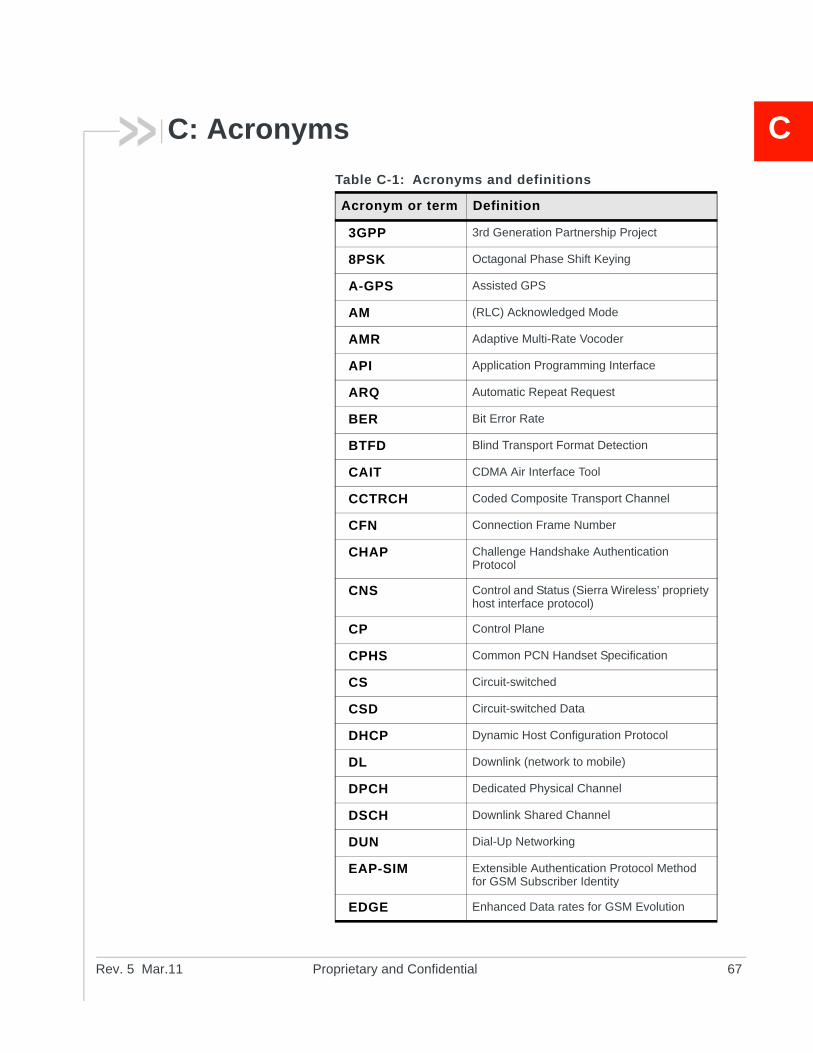
Rev. 5 Ma
C
C: AcronymsTable C-1: Acronyms and definitions
Acronym or term Definition
3GPP 3rd Generation Partnership Project
8PSK Octagonal Phase Shift Keying
A-GPS Assisted GPS
AM (RLC) Acknowledged Mode
AMR Adaptive Multi-Rate Vocoder
API Application Programming Interface
ARQ Automatic Repeat Request
BER Bit Error Rate
BTFD Blind Transport Format Detection
CAIT CDMA Air Interface Tool
CCTRCH Coded Composite Transport Channel
CFN Connection Frame Number
CHAP Challenge Handshake Authentication Protocol
CNS Control and Status (Sierra Wireless’ propriety host interface protocol)
CP Control Plane
CPHS Common PCN Handset Specification
CS Circuit-switched
CSD Circuit-switched Data
DHCP Dynamic Host Configuration Protocol
DL Downlink (network to mobile)
DPCH Dedicated Physical Channel
DSCH Downlink Shared Channel
DUN Dial-Up Networking
EAP-SIM Extensible Authentication Protocol Method for GSM Subscriber Identity
EDGE Enhanced Data rates for GSM Evolution
r.11 Proprietary and Confidential 67
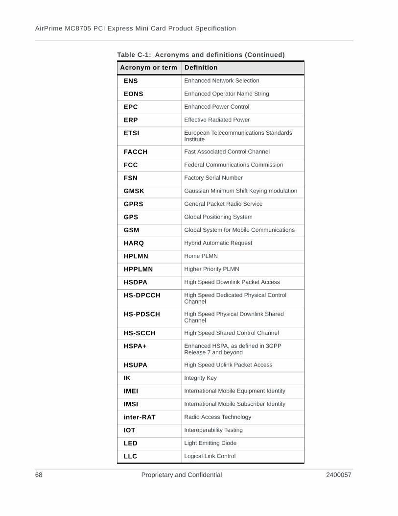
AirPrime MC8705 PCI Express Mini Card Product Specification
ENS Enhanced Network Selection
EONS Enhanced Operator Name String
EPC Enhanced Power Control
ERP Effective Radiated Power
ETSI European Telecommunications Standards Institute
FACCH Fast Associated Control Channel
FCC Federal Communications Commission
FSN Factory Serial Number
GMSK Gaussian Minimum Shift Keying modulation
GPRS General Packet Radio Service
GPS Global Positioning System
GSM Global System for Mobile Communications
HARQ Hybrid Automatic Request
HPLMN Home PLMN
HPPLMN Higher Priority PLMN
HSDPA High Speed Downlink Packet Access
HS-DPCCH High Speed Dedicated Physical Control Channel
HS-PDSCH High Speed Physical Downlink Shared Channel
HS-SCCH High Speed Shared Control Channel
HSPA+ Enhanced HSPA, as defined in 3GPP Release 7 and beyond
HSUPA High Speed Uplink Packet Access
IK Integrity Key
IMEI International Mobile Equipment Identity
IMSI International Mobile Subscriber Identity
inter-RAT Radio Access Technology
IOT Interoperability Testing
LED Light Emitting Diode
LLC Logical Link Control
Table C-1: Acronyms and definitions (Continued)
Acronym or term Definition
68 Proprietary and Confidential 2400057
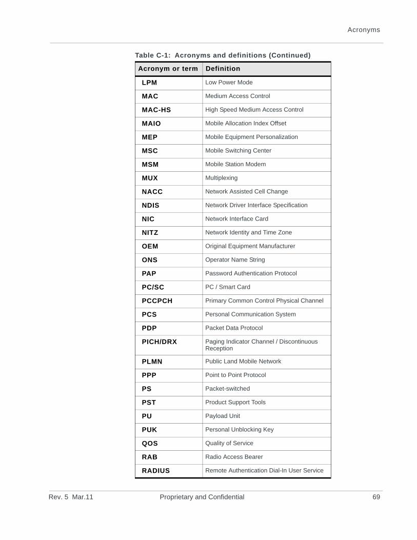
Acronyms
LPM Low Power Mode
MAC Medium Access Control
MAC-HS High Speed Medium Access Control
MAIO Mobile Allocation Index Offset
MEP Mobile Equipment Personalization
MSC Mobile Switching Center
MSM Mobile Station Modem
MUX Multiplexing
NACC Network Assisted Cell Change
NDIS Network Driver Interface Specification
NIC Network Interface Card
NITZ Network Identity and Time Zone
OEM Original Equipment Manufacturer
ONS Operator Name String
PAP Password Authentication Protocol
PC/SC PC / Smart Card
PCCPCH Primary Common Control Physical Channel
PCS Personal Communication System
PDP Packet Data Protocol
PICH/DRX Paging Indicator Channel / Discontinuous Reception
PLMN Public Land Mobile Network
PPP Point to Point Protocol
PS Packet-switched
PST Product Support Tools
PU Payload Unit
PUK Personal Unblocking Key
QOS Quality of Service
RAB Radio Access Bearer
RADIUS Remote Authentication Dial-In User Service
Table C-1: Acronyms and definitions (Continued)
Acronym or term Definition
Rev. 5 Mar.11 Proprietary and Confidential 69
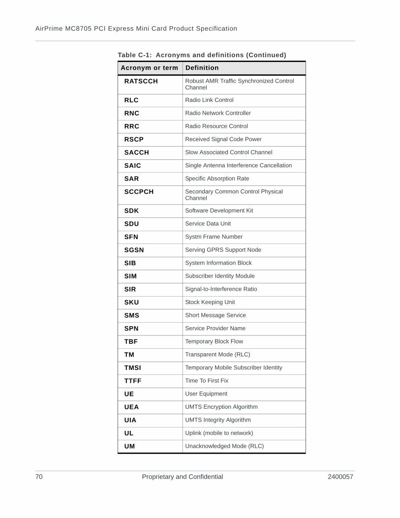
AirPrime MC8705 PCI Express Mini Card Product Specification
RATSCCH Robust AMR Traffic Synchronized Control Channel
RLC Radio Link Control
RNC Radio Network Controller
RRC Radio Resource Control
RSCP Received Signal Code Power
SACCH Slow Associated Control Channel
SAIC Single Antenna Interference Cancellation
SAR Specific Absorption Rate
SCCPCH Secondary Common Control Physical Channel
SDK Software Development Kit
SDU Service Data Unit
SFN Systm Frame Number
SGSN Serving GPRS Support Node
SIB System Information Block
SIM Subscriber Identity Module
SIR Signal-to-Interference Ratio
SKU Stock Keeping Unit
SMS Short Message Service
SPN Service Provider Name
TBF Temporary Block Flow
TM Transparent Mode (RLC)
TMSI Temporary Mobile Subscriber Identity
TTFF Time To First Fix
UE User Equipment
UEA UMTS Encryption Algorithm
UIA UMTS Integrity Algorithm
UL Uplink (mobile to network)
UM Unacknowledged Mode (RLC)
Table C-1: Acronyms and definitions (Continued)
Acronym or term Definition
70 Proprietary and Confidential 2400057
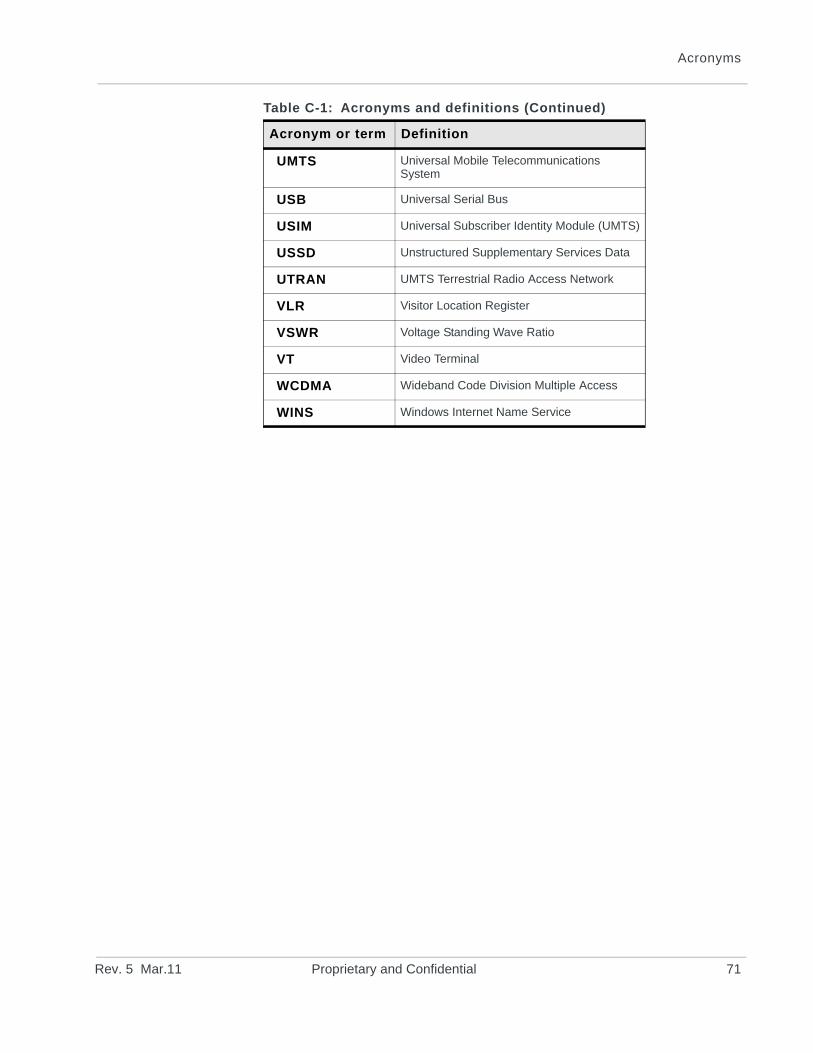
Acronyms
UMTS Universal Mobile Telecommunications System
USB Universal Serial Bus
USIM Universal Subscriber Identity Module (UMTS)
USSD Unstructured Supplementary Services Data
UTRAN UMTS Terrestrial Radio Access Network
VLR Visitor Location Register
VSWR Voltage Standing Wave Ratio
VT Video Terminal
WCDMA Wideband Code Division Multiple Access
WINS Windows Internet Name Service
Table C-1: Acronyms and definitions (Continued)
Acronym or term Definition
Rev. 5 Mar.11 Proprietary and Confidential 71
AirPrime MC8705 PCI Express Mini Card Product Specification
72 Proprietary and Confidential 2400057


![PCI Express to PCI-X Reversible Bridge · PDF filePCI Express to PCI-X Reversible Bridge Revision 2.5 ... 7.5.135 bit [30] of Replay and ... 6 PCI EXPRESS FUNCTIONAL OVERVIEW](https://img.pdfslide.us/doc/110x75/5ab0dd047f8b9a00728b95ba/pci-express-to-pci-x-reversible-bridge-express-to-pci-x-reversible-bridge-revision.jpg)