Embed Size (px)
Citation preview

AirPrime MC7455
Hardware Integration Guide
4118013
Rev 1
Proprietary and Confidential
Contents subject to change

Preface
Rev 1 Sep.15 Proprietary and Confidential - Contents subject to change 3
Important
Notice
Due to the nature of wireless communications, transmission and reception of data
can never be guaranteed. Data may be delayed, corrupted (i.e., have errors) or be
totally lost. Although significant delays or losses of data are rare when wireless
devices such as the Sierra Wireless modem are used in a normal manner with a
well-constructed network, the Sierra Wireless modem should not be used in
situations where failure to transmit or receive data could result in damage of any
kind to the user or any other party, including but not limited to personal injury,
death, or loss of property. Sierra Wireless accepts no responsibility for damages
of any kind resulting from delays or errors in data transmitted or received using
the Sierra Wireless modem, or for failure of the Sierra Wireless modem to
transmit or receive such data.
Safety and
Hazards
Do not operate the Sierra Wireless modem in areas where blasting is in progress,
where explosive atmospheres may be present, near medical equipment, near life
support equipment, or any equipment which may be susceptible to any form of
radio interference. In such areas, the Sierra Wireless modem MUST BE
POWERED OFF. The Sierra Wireless modem can transmit signals that could
interfere with this equipment.
Do not operate the Sierra Wireless modem in any aircraft, whether the aircraft is
on the ground or in flight. In aircraft, the Sierra Wireless modem MUST BE
POWERED OFF. When operating, the Sierra Wireless modem can transmit
signals that could interfere with various onboard systems.
Note: Some airlines may permit the use of cellular phones while the aircraft is on the
ground and the door is open. Sierra Wireless modems may be used at this time.
The driver or operator of any vehicle should not operate the Sierra Wireless
modem while in control of a vehicle. Doing so will detract from the driver or
operator's control and operation of that vehicle. In some states and provinces,
operating such communications devices while in control of a vehicle is an offence.
Limitation of
Liability
The information in this manual is subject to change without notice and does not
represent a commitment on the part of Sierra Wireless. SIERRA WIRELESS AND
ITS AFFILIATES SPECIFICALLY DISCLAIM LIABILITY FOR ANY AND ALL
DIRECT, INDIRECT, SPECIAL, GENERAL, INCIDENTAL, CONSEQUENTIAL,
PUNITIVE OR EXEMPLARY DAMAGES INCLUDING, BUT NOT LIMITED TO,
LOSS OF PROFITS OR REVENUE OR ANTICIPATED PROFITS OR REVENUE
ARISING OUT OF THE USE OR INABILITY TO USE ANY SIERRA WIRELESS
PRODUCT, EVEN IF SIERRA WIRELESS AND/OR ITS AFFILIATES HAS BEEN
ADVISED OF THE POSSIBILITY OF SUCH DAMAGES OR THEY ARE
FORESEEABLE OR FOR CLAIMS BY ANY THIRD PARTY.
Notwithstanding the foregoing, in no event shall Sierra Wireless and/or its
affiliates aggregate liability arising under or in connection with the Sierra Wireless
product, regardless of the number of events, occurrences, or claims giving rise to
liability, be in excess of the price paid by the purchaser for the Sierra Wireless
product.
Hardware Integration Guide
4 Proprietary and Confidential - Contents subject to change 4118013
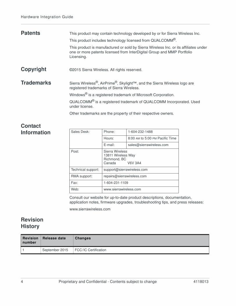
Patents This product may contain technology developed by or for Sierra Wireless Inc.
This product includes technology licensed from QUALCOMM®.
This product is manufactured or sold by Sierra Wireless Inc. or its affiliates under
one or more patents licensed from InterDigital Group and MMP Portfolio
Licensing.
Copyright ©2015 Sierra Wireless. All rights reserved.
Trademarks Sierra Wireless®, AirPrime®, Skylight™, and the Sierra Wireless logo are
registered trademarks of Sierra Wireless.
Windows® is a registered trademark of Microsoft Corporation.
QUALCOMM® is a registered trademark of QUALCOMM Incorporated. Used
under license.
Other trademarks are the property of their respective owners.
Contact
Information
Consult our website for up-to-date product descriptions, documentation,
application notes, firmware upgrades, troubleshooting tips, and press releases:
www.sierrawireless.com
Revision
History
Sales Desk: Phone: 1-604-232-1488
Hours: 8:00 AM to 5:00 PM Pacific Time
E-mail: [email protected]
Post: Sierra Wireless13811 Wireless WayRichmond, BCCanada V6V 3A4
Technical support: [email protected]
RMA support: [email protected]
Fax: 1-604-231-1109
Web: www.sierrawireless.com
Revision
number
Release date Changes
1 September 2015 FCC / IC Certification
Rev 1 Sep.15 Proprietary and Confidential - Contents subject to change 5
Contents
Introduction . . . . . . . . . . . . . . . . . . . . . . . . . . . . . . . . . . . . . . . . . . . . . . . . . . . . .7
Accessories . . . . . . . . . . . . . . . . . . . . . . . . . . . . . . . . . . . . . . . . . . . . . . . . . . 7
Required Connectors . . . . . . . . . . . . . . . . . . . . . . . . . . . . . . . . . . . . . . . . . . . 7
Power . . . . . . . . . . . . . . . . . . . . . . . . . . . . . . . . . . . . . . . . . . . . . . . . . . . . . . . . . .9
Power Supply . . . . . . . . . . . . . . . . . . . . . . . . . . . . . . . . . . . . . . . . . . . . . . . . . 9
Module Power States . . . . . . . . . . . . . . . . . . . . . . . . . . . . . . . . . . . . . . . . . . . 9
RF Specifications . . . . . . . . . . . . . . . . . . . . . . . . . . . . . . . . . . . . . . . . . . . . . . .11
RF Connections . . . . . . . . . . . . . . . . . . . . . . . . . . . . . . . . . . . . . . . . . . . . . . 12
Shielding . . . . . . . . . . . . . . . . . . . . . . . . . . . . . . . . . . . . . . . . . . . . . . . . .12
Antenna and Cabling . . . . . . . . . . . . . . . . . . . . . . . . . . . . . . . . . . . . . . . .12
Ground Connection . . . . . . . . . . . . . . . . . . . . . . . . . . . . . . . . . . . . . . . . . . . 13
Interference and Sensitivity . . . . . . . . . . . . . . . . . . . . . . . . . . . . . . . . . . . . . 13
Interference From Other Wireless Devices . . . . . . . . . . . . . . . . . . . . . . .14
Host-generated RF Interference . . . . . . . . . . . . . . . . . . . . . . . . . . . . . . .14
Device-generated RF Interference . . . . . . . . . . . . . . . . . . . . . . . . . . . . . .14
Methods to Mitigate Decreased Rx Performance . . . . . . . . . . . . . . . . . .15
Radiated Spurious Emissions (RSE) . . . . . . . . . . . . . . . . . . . . . . . . . . . .15
Radiated Sensitivity Measurement. . . . . . . . . . . . . . . . . . . . . . . . . . . . . . . . 15
Regulatory Compliance and Industry Certifications . . . . . . . . . . . . . . . . . . .17
Important Notice . . . . . . . . . . . . . . . . . . . . . . . . . . . . . . . . . . . . . . . . . . . . . . 17
Safety and Hazards . . . . . . . . . . . . . . . . . . . . . . . . . . . . . . . . . . . . . . . . . . . 18
Important Compliance Information For North American Users . . . . . . . . . . 18
Acronyms . . . . . . . . . . . . . . . . . . . . . . . . . . . . . . . . . . . . . . . . . . . . . . . . . . . . .21
Index . . . . . . . . . . . . . . . . . . . . . . . . . . . . . . . . . . . . . . . . . . . . . . . . . . . . . . . . . 23

Hardware Integration Guide
6 Proprietary and Confidential - Contents subject to change 4118013
Rev 1 Sep.15 Proprietary and Confidential - Contents subject to change 7
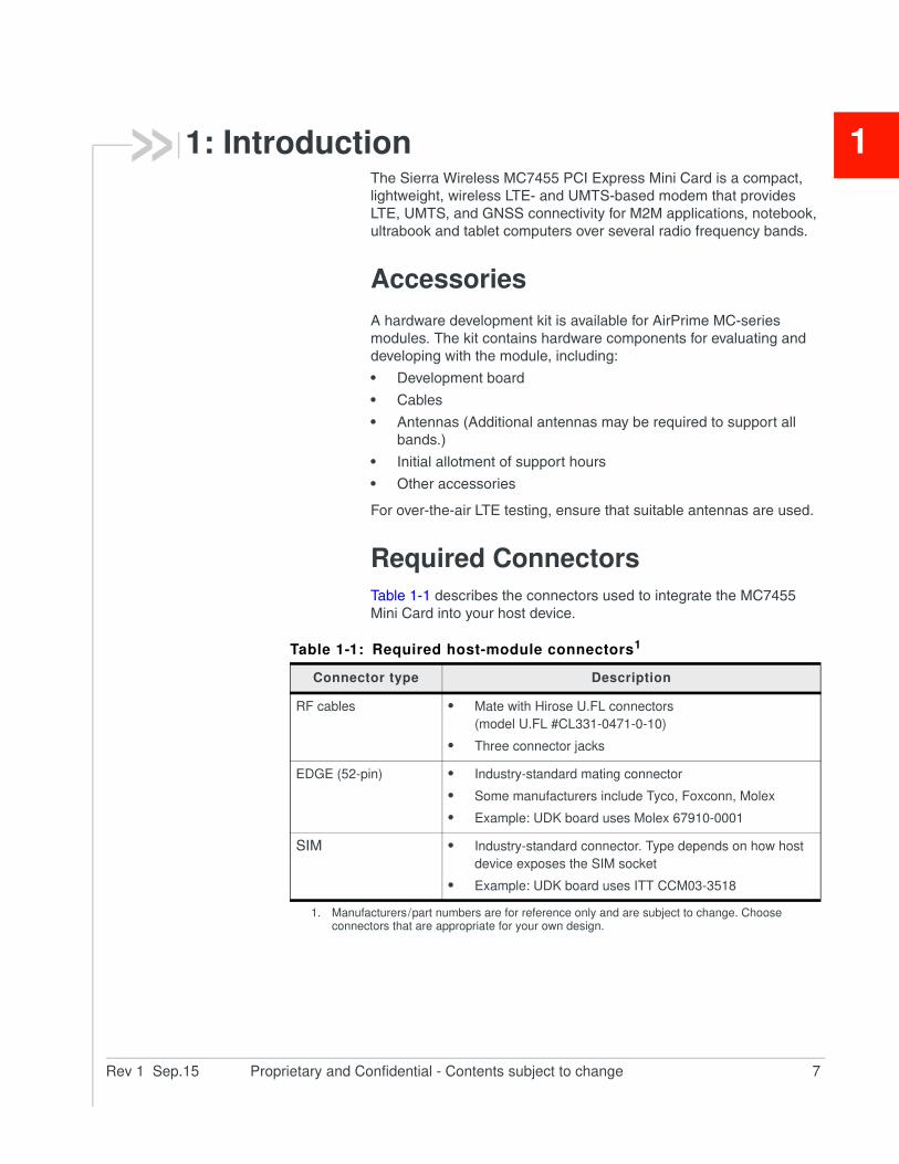
11: IntroductionThe Sierra Wireless MC7455 PCI Express Mini Card is a compact,
lightweight, wireless LTE- and UMTS-based modem that provides
LTE, UMTS, and GNSS connectivity for M2M applications, notebook,
ultrabook and tablet computers over several radio frequency bands.
Accessories
A hardware development kit is available for AirPrime MC-series
modules. The kit contains hardware components for evaluating and
developing with the module, including:
• Development board
• Cables
• Antennas (Additional antennas may be required to support all
bands.)
• Initial allotment of support hours
• Other accessories
For over-the-air LTE testing, ensure that suitable antennas are used.
Required Connectors
Table 1-1 describes the connectors used to integrate the MC7455
Mini Card into your host device.
Table 1-1: Required host-module connectors1
Connector type Description
RF cables • Mate with Hirose U.FL connectors
(model U.FL #CL331-0471-0-10)
• Three connector jacks
EDGE (52-pin) • Industry-standard mating connector
• Some manufacturers include Tyco, Foxconn, Molex
• Example: UDK board uses Molex 67910-0001
SIM • Industry-standard connector. Type depends on how host
device exposes the SIM socket
• Example: UDK board uses ITT CCM03-3518
1. Manufacturers / part numbers are for reference only and are subject to change. Choose connectors that are appropriate for your own design.
Hardware Integration Guide
8 Proprietary and Confidential - Contents subject to change 4118013
Rev 1 Sep.15 Proprietary and Confidential - Contents subject to change 9
22: Power
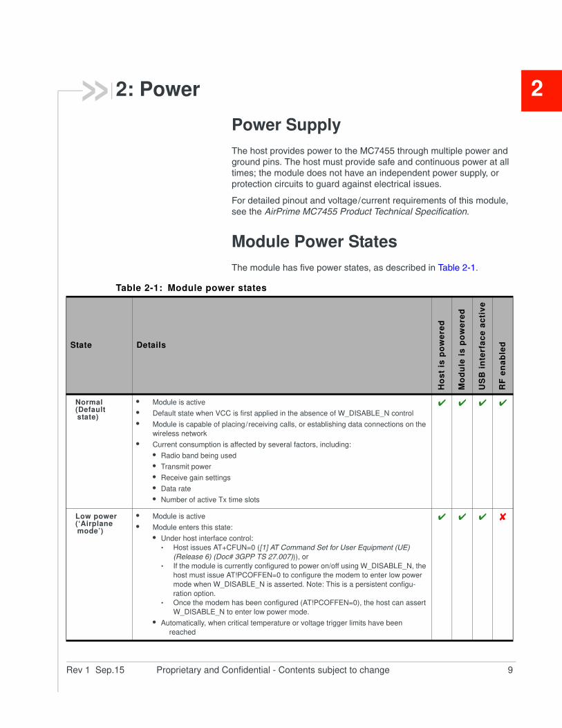
Power Supply
The host provides power to the MC7455 through multiple power and
ground pins. The host must provide safe and continuous power at all
times; the module does not have an independent power supply, or
protection circuits to guard against electrical issues.
For detailed pinout and voltage / current requirements of this module,
see the AirPrime MC7455 Product Technical Specification.
Module Power States
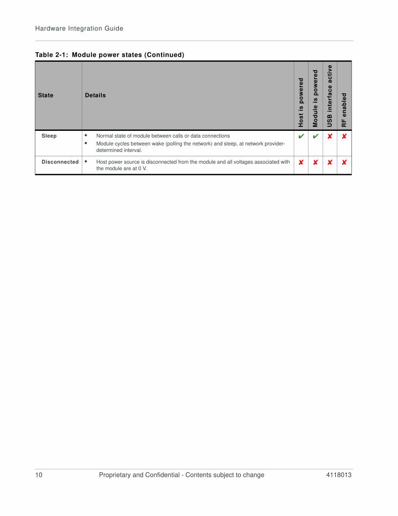
The module has five power states, as described in Table 2-1.
Table 2-1: Module power states
State Details
Ho
st
is p
ow
ere
d
Mo
du
le i
s p
ow
ere
d
US
B i
nte
rfa
ce
ac
tiv
e
RF
en
ab
led
Normal(Default state)
• Module is active
• Default state when VCC is first applied in the absence of W_DISABLE_N control
• Module is capable of placing / receiving calls, or establishing data connections on the
wireless network
• Current consumption is affected by several factors, including:
• Radio band being used
• Transmit power
• Receive gain settings
• Data rate
• Number of active Tx time slots
Low power(‘Airplane mode’)
• Module is active
• Module enters this state:
• Under host interface control:
· Host issues AT+CFUN=0 ([1] AT Command Set for User Equipment (UE)
(Release 6) (Doc# 3GPP TS 27.007))), or
· If the module is currently configured to power on/off using W_DISABLE_N, the
host must issue AT!PCOFFEN=0 to configure the modem to enter low power
mode when W_DISABLE_N is asserted. Note: This is a persistent configu-
ration option.
· Once the modem has been configured (AT!PCOFFEN=0), the host can assert
W_DISABLE_N to enter low power mode.
• Automatically, when critical temperature or voltage trigger limits have been
reached
Hardware Integration Guide
10 Proprietary and Confidential - Contents subject to change 4118013
Sleep • Normal state of module between calls or data connections
• Module cycles between wake (polling the network) and sleep, at network provider-
determined interval.
Disconnected • Host power source is disconnected from the module and all voltages associated with
the module are at 0 V.
Table 2-1: Module power states (Continued)
State Details
Ho
st
is p
ow
ere
d
Mo
du
le i
s p
ow
ere
d
US
B i
nte
rfa
ce
ac
tiv
e
RF
en
ab
led
Rev 1 Sep.15 Proprietary and Confidential - Contents subject to change 11
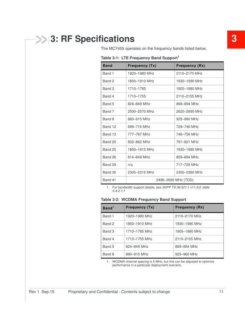
33: RF SpecificationsThe MC7455 operates on the frequency bands listed below.
Table 3-1: LTE Frequency Band Support1
1. For bandwidth support details, see 3GPP TS 36.521-1 v11.3.0, table 5.4.2.1-1
Band Frequency (Tx) Frequency (Rx)
Band 1 1920–1980 MHz 2110–2170 MHz
Band 2 1850–1910 MHz 1930–1990 MHz
Band 3 1710–1785 1805–1880 MHz
Band 4 1710–1755 2110–2155 MHz
Band 5 824–849 MHz 869–894 MHz
Band 7 2500–2570 MHz 2620–2690 MHz
Band 8 880–915 MHz 925–960 MHz
Band 12 699–716 MHz 729–746 MHz
Band 13 777–787 MHz 746–756 MHz
Band 20 832–862 MHz 791–821 MHz
Band 25 1850–1915 MHz 1930–1995 MHz
Band 26 814–849 MHz 859–894 MHz
Band 29 n/a 717–728 MHz
Band 30 2305–2315 MHz 2350–2360 MHz
Band 41 2496–2690 MHz (TDD)
Table 3-2: WCDMA Frequency Band Support
Band1
1. WCDMA channel spacing is 5 MHz, but this can be adjusted to optimize performance in a particular deployment scenario.
Frequency (Tx) Frequency (Rx)
Band 1 1920–1980 MHz 2110–2170 MHz
Band 2 1850–1910 MHz 1930–1990 MHz
Band 3 1710–1785 MHz 1805–1880 MHz
Band 4 1710–1755 MHz 2110–2155 MHz
Band 5 824–849 MHz 869–894 MHz
Band 8 880–915 MHz 925–960 MHz
Hardware Integration Guide
12 Proprietary and Confidential - Contents subject to change 4118013
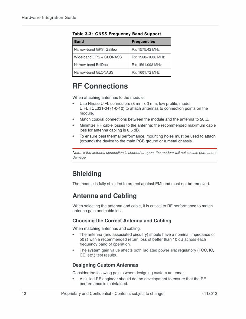
RF Connections
When attaching antennas to the module:
• Use Hirose U.FL connectors (3 mm x 3 mm, low profile; model
U.FL #CL331-0471-0-10) to attach antennas to connection points on the
module.
• Match coaxial connections between the module and the antenna to 50 .
• Minimize RF cable losses to the antenna; the recommended maximum cable
loss for antenna cabling is 0.5 dB.
• To ensure best thermal performance, mounting holes must be used to attach
(ground) the device to the main PCB ground or a metal chassis.
Note: If the antenna connection is shorted or open, the modem will not sustain permanent
damage.
Shielding
The module is fully shielded to protect against EMI and must not be removed.
Antenna and Cabling
When selecting the antenna and cable, it is critical to RF performance to match
antenna gain and cable loss.
Choosing the Correct Antenna and Cabling
When matching antennas and cabling:
• The antenna (and associated circuitry) should have a nominal impedance of
50 with a recommended return loss of better than 10 dB across each
frequency band of operation.
• The system gain value affects both radiated power and regulatory (FCC, IC,
CE, etc.) test results.
Designing Custom Antennas
Consider the following points when designing custom antennas:
• A skilled RF engineer should do the development to ensure that the RF
performance is maintained.
Table 3-3: GNSS Frequency Band Support
Band Frequencies
Narrow-band GPS, Galileo Rx: 1575.42 MHz
Wide-band GPS + GLONASS Rx: 1560–1606 MHz
Narrow-band BeiDou Rx: 1561.098 MHz
Narrow-band GLONASS Rx: 1601.72 MHz
RF Specifications
Rev 1 Sep.15 Proprietary and Confidential - Contents subject to change 13
• If both UMTS and CDMA modules will be installed in the same platform, you
may want to develop separate antennas for maximum performance.
Determining the Antenna’s Location
When deciding where to put the antennas:
• Antenna location may affect RF performance. Although the module is
shielded to prevent interference in most applications, the placement of the
antenna is still very important — if the host device is insufficiently shielded,
high levels of broadband or spurious noise can degrade the module’s perfor-
mance.
• Connecting cables between the module and the antenna must have 50
impedance. If the impedance of the module is mismatched, RF performance
is reduced significantly.
• Antenna cables should be routed, if possible, away from noise sources
(switching power supplies, LCD assemblies, etc.). If the cables are near the
noise sources, the noise may be coupled into the RF cable and into the
antenna.
Disabling the Diversity Antenna
Use the AT command !RXDEN=0 to disable receive diversity or !RXDEN=1 to
enable receive diversity.
Note: A diversity antenna is used to improve connection quality and reliability through
redundancy. Because two antennas may experience difference interference effects (signal
distortion, delay, etc.), when one antenna receives a degraded signal, the other may not be
similarly affected.
Ground ConnectionWhen connecting the module to system ground:
• Prevent noise leakage by establishing a very good ground connection to the
module through the host connector.
• Connect to system ground using the two mounting holes at the top of the
module.
• Minimize ground noise leakage into the RF.Depending on the host board design, noise could potentially be coupled to
the module from the host board. This is mainly an issue for host designs that
have signals traveling along the length of the module, or circuitry operating at
both ends of the module interconnects.
Interference and Sensitivity
Several interference sources can affect the module’s RF performance
(RF desense). Common sources include power supply noise and device-
generated RF.
Hardware Integration Guide
14 Proprietary and Confidential - Contents subject to change 4118013
RF desense can be addressed through a combination of mitigation techniques
(Methods to Mitigate Decreased Rx Performance on page 15) and radiated
sensitivity measurement (Radiated Sensitivity Measurement on page 15).
Note: The MC7455 is based on ZIF (Zero Intermediate Frequency) technologies. When
performing EMC (Electromagnetic Compatibility) tests, there are no IF (Intermediate
Frequency) components from the module to consider.
Interference From Other Wireless Devices
Wireless devices operating inside the host device can cause interference that
affects the module.
To determine the most suitable locations for antennas on your host device,
evaluate each wireless device’s radio system, considering the following:
• Any harmonics, sub-harmonics, or cross-products of signals generated by
wireless devices that fall in the module’s Rx range may cause spurious
response, resulting in decreased Rx performance.
• The Tx power and corresponding broadband noise of other wireless devices
may overload or increase the noise floor of the module’s receiver, resulting in
Rx desense.
The severity of this interference depends on the closeness of the other antennas
to the module’s antenna. To determine suitable locations for each wireless
device’s antenna, thoroughly evaluate your host device’s design.
Host-generated RF Interference
All electronic computing devices generate RF interference that can negatively
affect the receive sensitivity of the module.
Proximity of host electronics to the antenna in wireless devices can contribute to
decreased Rx performance. Components that are most likely to cause this
include:
• Microprocessor and memory
• Display panel and display drivers
• Switching-mode power supplies
Device-generated RF Interference
The module can cause interference with other devices. Wireless devices such as
AirPrime embedded modules transmit in bursts (pulse transients) for set durations
(RF burst frequencies). Hearing aids and speakers convert these burst
frequencies into audible frequencies, resulting in audible noise.
RF Specifications
Rev 1 Sep.15 Proprietary and Confidential - Contents subject to change 15
Methods to Mitigate Decreased Rx Performance
It is important to investigate sources of localized interference early in the design
cycle. To reduce the effect of device-generated RF on Rx performance:
• Put the antenna as far as possible from sources of interference. The
drawback is that the module may be less convenient to use.
• Shield the host device. The module itself is well shielded to avoid external
interference. However, the antenna cannot be shielded for obvious reasons.
In most instances, it is necessary to employ shielding on the components of
the host device (such as the main processor and parallel bus) that have the
highest RF emissions.
• Filter out unwanted high-order harmonic energy by using discrete filtering on
low frequency lines.
• Form shielding layers around high-speed clock traces by using multi-layer
PCBs.
• Route antenna cables away from noise sources.
Radiated Spurious Emissions (RSE)
When designing an antenna for use with AirPrime embedded modules, the host
device with an AirPrime embedded module must satisfy any applicable
standards / local regulatory bodies for radiated spurious emission (RSE) for
receive-only mode and for transmit mode (transmitter is operating).
Note that antenna impedance affects radiated emissions, which must be
compared against the conducted 50-ohm emissions baseline. (AirPrime
embedded modules meet the 50-ohm conducted emissions requirement.)
Radiated Sensitivity Measurement
A wireless host device contains many noise sources that contribute to a reduction
in Rx performance.
To determine the extent of any receiver performance desensitization due to self-
generated noise in the host device, over-the-air (OTA) or radiated testing is
required. This testing can be performed by Sierra Wireless or you can use your
own OTA test chamber for in-house testing.

Hardware Integration Guide
16 Proprietary and Confidential - Contents subject to change 4118013
Rev 1 Sep.15 Proprietary and Confidential - Contents subject to change 17
44: Regulatory Compliance and Industry Certifications
This module is designed to meet, and upon commercial release will
meet, the requirements of the following regulatory bodies and
regulations, where applicable:
• Federal Communications Commission (FCC) of the United States
• The Certification and Engineering Bureau of Industry Canada
(IC)
• The National Communications Commission (NCC) of Taiwan,
Republic of China
• Ministry of Internal Affairs and Communications (MIC) of Japan
• Radio Equipment and Telecommunications Terminal Equipment
(R&TTE) Directive of the European Union
Upon commercial release, the following industry certifications will
have been obtained, where applicable:
• GCF
• PTCRB
Additional certifications and details on specific country approvals may
be obtained upon customer request — contact your Sierra Wireless
account representative for details.
Additional testing and certification may be required for the end
product with an embedded MC7455 module and are the
responsibility of the OEM. Sierra Wireless offers professional
services-based assistance to OEMs with the testing and certification
process, if required.
Important Notice
Because of the nature of wireless communications, transmission and
reception of data can never be guaranteed. Data may be delayed,
corrupted (i.e., have errors) or be totally lost. Although significant
delays or losses of data are rare when wireless devices such as the
Sierra Wireless module are used in a normal manner with a well-
constructed network, the Sierra Wireless module should not be used
in situations where failure to transmit or receive data could result in
damage of any kind to the user or any other party, including but not
limited to personal injury, death, or loss of property. Sierra Wireless
and its affiliates accept no responsibility for damages of any kind
resulting from delays or errors in data transmitted or received using
the Sierra Wireless module, or for failure of the Sierra Wireless
module to transmit or receive such data.
Hardware Integration Guide
18 Proprietary and Confidential - Contents subject to change 4118013
Safety and Hazards
Do not operate your MC7455 module:
• In areas where blasting is in progress
• Where explosive atmospheres may be present including refuelling points, fuel
depots, and chemical plants
• Near medical equipment, life support equipment, or any equipment which
may be susceptible to any form of radio interference. In such areas, the
MC7455 module MUST BE POWERED OFF. Otherwise, the MC7455 module
can transmit signals that could interfere with this equipment.
In an aircraft, the MC7455 module MUST BE POWERED OFF. Otherwise, the
MC7455 module can transmit signals that could interfere with various onboard
systems and may be dangerous to the operation of the aircraft or disrupt the
cellular network. Use of a cellular phone in an aircraft is illegal in some
jurisdictions. Failure to observe this instruction may lead to suspension or denial
of cellular telephone services to the offender, or legal action or both.
Some airlines may permit the use of cellular phones while the aircraft is on the
ground and the door is open. The MC7455 module may be used normally at this
time.
Important Compliance Information For
North American Users
The MC7455 module, upon commercial release, will have been granted modular
approval for mobile applications. Integrators may use the MC7455 module in their
final products without additional FCC / IC (Industry Canada) certification if they
meet the following conditions. Otherwise, additional FCC / IC approvals must be
obtained.
1. At least 20 cm separation distance between the antenna and the user’s body
must be maintained at all times.
2. To comply with FCC / IC regulations limiting both maximum RF output power
and human exposure to RF radiation, the maximum antenna gain including
cable loss in a mobile-only exposure condition must not exceed the limits
stipulated in Table 4-1 on page 19.
Regulatory Compliance and Industry Certifications
Rev 1 Sep.15 Proprietary and Confidential - Contents subject to change 19
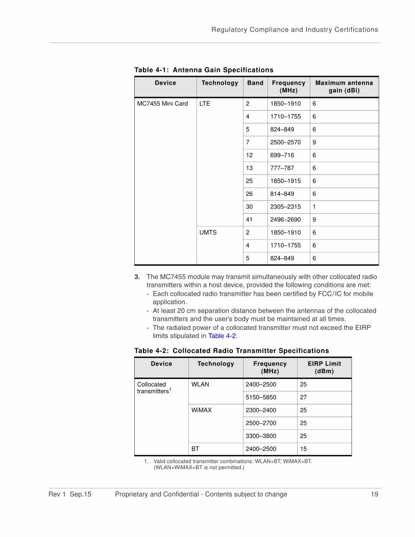
3. The MC7455 module may transmit simultaneously with other collocated radio
transmitters within a host device, provided the following conditions are met:
· Each collocated radio transmitter has been certified by FCC / IC for mobile
application.
· At least 20 cm separation distance between the antennas of the collocated
transmitters and the user’s body must be maintained at all times.
· The radiated power of a collocated transmitter must not exceed the EIRP
limits stipulated in Table 4-2.
Table 4-1: Antenna Gain Specifications
Device Technology Band Frequency
(MHz)
Maximum antenna
gain (dBi)
MC7455 Mini Card LTE 2 1850–1910 6
4 1710–1755 6
5 824–849 6
7 2500–2570 9
12 699–716 6
13 777–787 6
25 1850–1915 6
26 814–849 6
30 2305–2315 1
41 2496–2690 9
UMTS 2 1850–1910 6
4 1710–1755 6
5 824–849 6
Table 4-2: Collocated Radio Transmitter Specifications
Device Technology Frequency
(MHz)
EIRP Limit
(dBm)
Collocated transmitters1
1. Valid collocated transmitter combinations: WLAN+BT; WiMAX+BT.(WLAN+WiMAX+BT is not permitted.)
WLAN 2400–2500 25
5150–5850 27
WiMAX 2300–2400 25
2500–2700 25
3300–3800 25
BT 2400–2500 15
Hardware Integration Guide
20 Proprietary and Confidential - Contents subject to change 4118013
4. A label must be affixed to the outside of the end product into which the
MC7455 module is incorporated, with a statement similar to the following:
· This device contains FCC ID: N7NMC7455Contains transmitter module IC: 2417C-MC7455 where 2417C-MC7455
is the module’s certification number.
5. A user manual with the end product must clearly indicate the operating
requirements and conditions that must be observed to ensure compliance
with current FCC / IC RF exposure guidelines.
The end product with an embedded MC7455 module may also need to pass the
FCC Part 15 unintentional emission testing requirements and be properly
authorized per FCC Part 15.
Note: If this module is intended for use in a portable device, you are responsible
for separate approval to satisfy the SAR requirements of FCC Part 2.1093 and
IC RSS-102.
Rev 1 Sep.15 Proprietary and Confidential - Contents subject to change 21
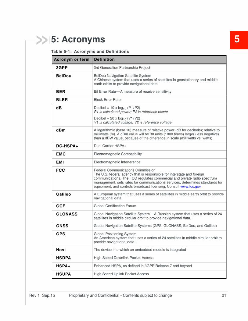
55: AcronymsTable 5-1: Acronyms and Definitions
Acronym or term Definition
3GPP 3rd Generation Partnership Project
BeiDou BeiDou Navigation Satellite SystemA Chinese system that uses a series of satellites in geostationary and middle earth orbits to provide navigational data.
BER Bit Error Rate — A measure of receive sensitivity
BLER Block Error Rate
dB Decibel = 10 x log10 (P1 / P2)P1 is calculated power; P2 is reference power
Decibel = 20 x log10 (V1 / V2)V1 is calculated voltage, V2 is reference voltage
dBm A logarithmic (base 10) measure of relative power (dB for decibels); relative to milliwatts (m). A dBm value will be 30 units (1000 times) larger (less negative) than a dBW value, because of the difference in scale (milliwatts vs. watts).
DC-HSPA+ Dual Carrier HSPA+
EMC Electromagnetic Compatibility
EMI Electromagnetic Interference
FCC Federal Communications CommissionThe U.S. federal agency that is responsible for interstate and foreign communications. The FCC regulates commercial and private radio spectrum management, sets rates for communications services, determines standards for equipment, and controls broadcast licensing. Consult www.fcc.gov.
Galileo A European system that uses a series of satellites in middle earth orbit to provide navigational data.
GCF Global Certification Forum
GLONASS Global Navigation Satellite System — A Russian system that uses a series of 24 satellites in middle circular orbit to provide navigational data.
GNSS Global Navigation Satellite Systems (GPS, GLONASS, BeiDou, and Galileo)
GPS Global Positioning SystemAn American system that uses a series of 24 satellites in middle circular orbit to provide navigational data.
Host The device into which an embedded module is integrated
HSDPA High Speed Downlink Packet Access
HSPA+ Enhanced HSPA, as defined in 3GPP Release 7 and beyond
HSUPA High Speed Uplink Packet Access
Hardware Integration Guide
22 Proprietary and Confidential - Contents subject to change 4118013
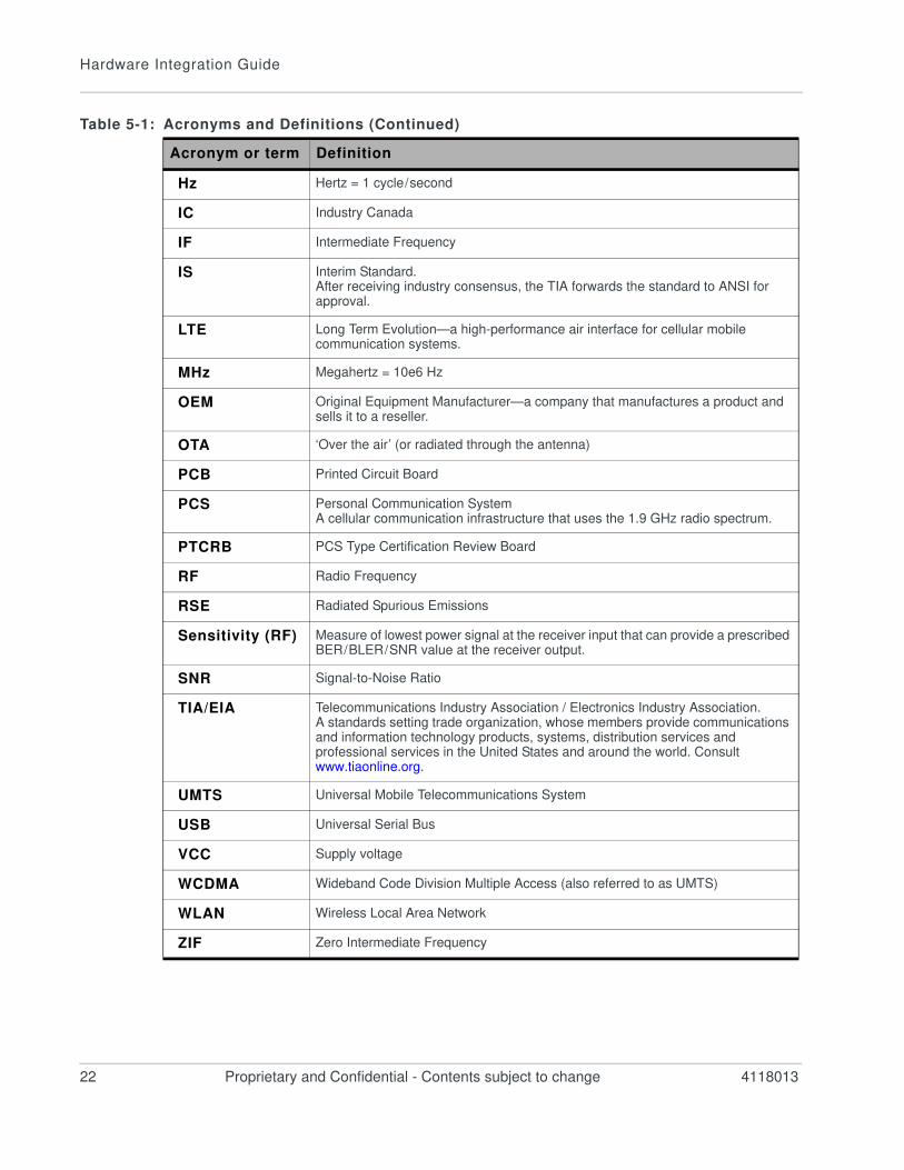
Hz Hertz = 1 cycle / second
IC Industry Canada
IF Intermediate Frequency
IS Interim Standard.After receiving industry consensus, the TIA forwards the standard to ANSI for approval.
LTE Long Term Evolution—a high-performance air interface for cellular mobile communication systems.
MHz Megahertz = 10e6 Hz
OEM Original Equipment Manufacturer—a company that manufactures a product and sells it to a reseller.
OTA ‘Over the air’ (or radiated through the antenna)
PCB Printed Circuit Board
PCS Personal Communication SystemA cellular communication infrastructure that uses the 1.9 GHz radio spectrum.
PTCRB PCS Type Certification Review Board
RF Radio Frequency
RSE Radiated Spurious Emissions
Sensitivity (RF) Measure of lowest power signal at the receiver input that can provide a prescribed BER / BLER / SNR value at the receiver output.
SNR Signal-to-Noise Ratio
TIA/EIA Telecommunications Industry Association / Electronics Industry Association.A standards setting trade organization, whose members provide communications and information technology products, systems, distribution services and professional services in the United States and around the world. Consult www.tiaonline.org.
UMTS Universal Mobile Telecommunications System
USB Universal Serial Bus
VCC Supply voltage
WCDMA Wideband Code Division Multiple Access (also referred to as UMTS)
WLAN Wireless Local Area Network
ZIF Zero Intermediate Frequency
Table 5-1: Acronyms and Definitions (Continued)
Acronym or term Definition
Rev 1 Sep.15 Proprietary and Confidential - Contents subject to change 23
Index
A
accessories, 7
acronyms and definitions, 21– 22
antenna
connection considerations, 12
custom, design, 12
diversity antenna, disabling, 13
limit, matching coaxial connections, 12
location, considerations, 13
matching, considerations, 12
maximum cable loss, 12
routing, 13
approvals, regulatory and industry, 17
B
bands supported, RF
LTE, 11
C
cable loss
antenna, maximum, 12
connection
grounding, 13
connectors, required
host-module, 7
D
desense. See RF
diversity antenna
disabling, 13
E
EDGE
connector, required, 7
F
filtering, RF desense, 15
frequency band support
LTE, 11
G
gain
maximum, 18
grounding
connection considerations, 13
I
impedance
module–antenna, 13
industry approvals, 17
interference
device generated, 14
host-generated, 14
wireless devices, 14
L
LTE
frequency band support, 11
M
module
power states, 9–??
N
noise
leakage, minimizing, 13
P
PCB
multi-layer, shielding for RF desense, 15
power
states, module, 9–??
R
radiated sensitivity measurement, 15
radiated spurious emissions, 15
regulatory approvals, 17
regulatory information, ??– 20
FCC, 18
limitation of liability, 17
safety and hazards, 18
Hardware Integration Guide
24 Proprietary and Confidential - Contents subject to change 4118013
RF
antenna cable loss, maximum, 12
antenna connection, considerations, 12
connectors, required, 7
desense
device-generated, 14
harmonic energy, filtering, 15
mitigation suggestions, 15
shielding suggestions, 15
interference
other devices, 14
wireless devices, 14
RF bands supported
LTE, 11
RF specifications, 11–??
RSE, 15
S
sensitivity
radiated measurement, overview, 15
shielding
module, compliance, 12
reducing RF desense, 15
SIM
connector, required, 7
specifications
RF, 11–??
Z
ZIF (Zero Intermediate Frequency), 14