Embed Size (px)
Citation preview
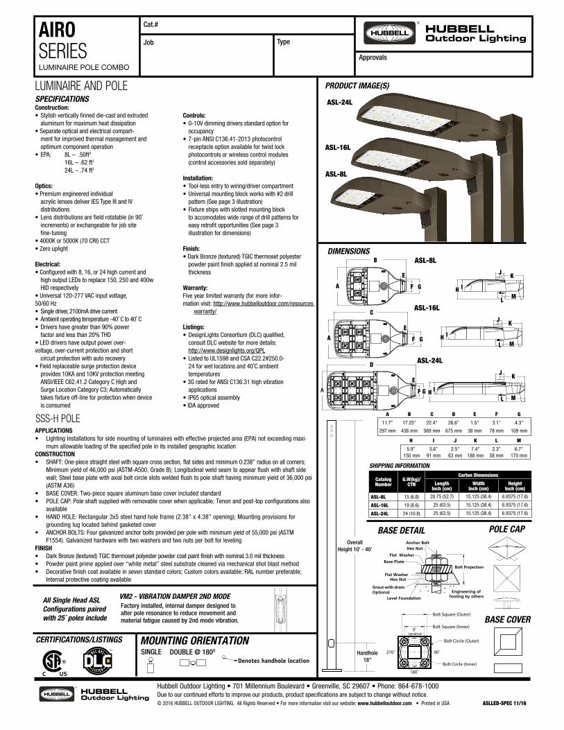
AIRO SERIESLUMINAIRE POLE COMBO
DIMENSIONS
PRODUCT IMAGE(S)
SPECIFICATIONS
CERTIFICATIONS/LISTINGS
Construction:• Stylish vertically finned die-cast and extruded aluminum for maximum heat dissipation• Separate optical and electrical compart- ment for improved thermal management and optimum component operation• EPA: 8L – .50ft2
16L – .62 ft2
24L – .74 ft2
Optics:• Premium engineered individual acrylic lenses deliver IES Type III and IV distributions• Lens distributions are field rotatable (in 90˚ increments) or exchangeable for job site fine-tuning• 4000K or 5000K (70 CRI) CCT• Zero uplight
Electrical:• Configured with 8, 16, or 24 high current and high output LEDs to replace 150, 250 and 400w HID respectively• Universal 120-277 VAC input voltage, 50/60 Hz • Single driver, 2100mA drive current• Ambient operating temperature -40˚ C to 40˚ C• Drivers have greater than 90% power factor and less than 20% THD• LED drivers have output power over- voltage, over-current protection and short circuit protection with auto recovery• Field replaceable surge protection device provides 10KA and 10KV protection meeting ANSI/IEEE C62.41.2 Category C High and Surge Location Category C3; Automatically takes fixture off-line for protection when device is consumed
Controls:• 0-10V dimming drivers standard option for occupancy • 7-pin ANSI C136.41-2013 photocontrol receptacle option available for twist lock photocontrols or wireless control modules (control accessories sold separately)
Installation:• Tool-less entry to wiring/driver compartment• Universal mounting block works with #2 drill pattern (See page 3 illustration)• Fixture ships with slotted mounting block to accomodates wide range of drill patterns for easy retrofit opportunities (See page 3 illustration for dimensions)
Finish:• Dark Bronze (textured) TGIC thermoset polyester powder paint finish applied at nominal 2.5 mil thickness
Warranty:Five year limited warranty (for more infor-mation visit: http://www.hubbelloutdoor.com/resources
warranty/
Listings:• DesignLights Consortium (DLC) qualified, consult DLC website for more details: http://www.designlights.org/QPL• Listed to UL1598 and CSA C22.2#250.0- 24 for wet locations and 40˚C ambient temperatures• 3G rated for ANSI C136.31 high vibration applications• IP65 optical assembly • IDA approved
Hubbell Outdoor Lighting • 701 Millennium Boulevard • Greenville, SC 29607 • Phone: 864-678-1000Due to our continued efforts to improve our products, product specifications are subject to change without notice.© 2016 HUBBELL OUTDOOR LIGHTING, All Rights Reserved • For more information visit our website: www.hubbelloutdoor.com • Printed in USA ASLLED-SPEC 11/16
Catalog Number
G.W(kg)/CTN
Carton Dimensions
Length Inch (cm)
Width Inch (cm)
Height Inch (cm)
ASL-8L 15 (6.8) 20.75 (52.7) 15.125 (38.4) 6.9375 (17.6)
ASL-16L 19 (8.6) 25 (63.5) 15.125 (38.4) 6.9375 (17.6)
ASL-24L 24 (10.8) 25 (63.5) 15.125 (38.4) 6.9375 (17.6)
SHIPPING INFORMATION
Cat.#
Approvals
Job Type
D
11.690
3.650
5.906
4.3533.118
22.387
7.354
6.740
2.562
2.335
1.525
26.639
11.690
5.906
3.650
2.562
7.354
6.7402.335
1.525
3.118 4.353
A F G
E
11.690
3.650
5.906
4.3533.118
22.387
7.354
6.740
2.562
2.335
1.525
26.639
11.690
5.906
3.650
2.562
7.354
6.7402.335
1.525
3.118 4.353
H I
J K
ML
11.690
3.650
5.906
4.3533.118
22.387
7.354
6.740
2.562
2.335
1.525
26.639
11.690
5.906
3.650
2.562
7.354
6.7402.335
1.525
3.118 4.353
IH
J K
L M
A B C D E F G
11.7” 17.25” 22.4” 26.6” 1.5" 3.1” 4.3”
297 mm 438 mm 569 mm 675 mm 38 mm 78 mm 109 mm
ASL-16L
ASL-8L
11.690
3.650
5.906
4.3533.118
22.387
7.354
6.740
2.562
2.335
1.525
26.639
11.690
5.906
3.650
2.562
7.354
6.7402.335
1.525
3.118 4.353
B
A F G
E
H I J K L M
5.9” 3.6” 2.5" 7.4" 2.3” 6.7” 150 mm 91 mm 63 mm 188 mm 58 mm 170 mm
ASL-16L
ASL-24L
11.690
3.650
5.906
4.3533.118
22.387
7.354
6.740
2.562
2.335
1.525
26.639
11.690
5.906
3.650
2.562
7.354
6.7402.335
1.525
3.118 4.353
H I
J K
ML
ASL-24L
C
11.690
3.650
5.906
4.3533.118
22.387
7.354
6.740
2.562
2.335
1.525
26.639
11.690
5.906
3.650
2.562
7.354
6.7402.335
1.525
3.118 4.353
A F G
E
ASL-8L
OverallHeight 10' - 40'
Handhole18"
OverallHeight 10'-30'
18"
TENON
Bolt Circle (Outer)
Bolt Circle (Inner)
Bolt Square (Outer)
Bolt Square (Inner)
Height of option in feet
BASE COVER
270˚ 90˚
180˚
0˚ Handhole
VIBRATION DAMPER2ND MODE
APPLICATIONS• Lighting installations for side mounting of luminaires with effective projected area (EPA) not exceeding maxi-
mum allowable loading of the specified pole in its installed geographic locationCONSTRUCTION• SHAFT: One-piece straight steel with square cross section, flat sides and minimum 0.238” radius on all corners;
Minimum yield of 46,000 psi (ASTM-A500, Grade B); Longitudinal weld seam to appear flush with shaft side wall; Steel base plate with axial bolt circle slots welded flush to pole shaft having minimum yield of 36,000 psi (ASTM A36)
• BASE COVER: Two-piece square aluminum base cover included standard• POLE CAP: Pole shaft supplied with removable cover when applicable; Tenon and post-top configurations also
available• HAND HOLE: Rectangular 3x5 steel hand hole frame (2.38” x 4.38” opening); Mounting provisions for
grounding lug located behind gasketed cover• ANCHOR BOLTS: Four galvanized anchor bolts provided per pole with minimum yield of 55,000 psi (ASTM
F1554). Galvanized hardware with two washers and two nuts per bolt for levelingFINISH• Dark Bronze (textured) TGIC thermoset polyester powder coat paint finish with nominal 3.0 mil thickness• Powder paint prime applied over “white metal” steel substrate cleaned via mechanical shot blast method• Decorative finish coat available in seven standard colors; Custom colors available; RAL number preferable;
Internal protective coating available
LUMINAIRE AND POLE
SSS-H POLE
Straight Square and Tapered Poles
Round Straight and Tapered Poles
Anchor BoltLocation in
Relationto ShaftRotation
Anchor BoltLocation in
Relationto ShaftRotation
Engineering offooting by others
Bolt Projection
Level Foundation
Grout with drainOptional
Hex Nut
Flat Washer
Base Plate
Flat Washer
Hex NutAnchor Bolt
Handhole Handhole
(All excluding RTA Group 1 & RTS Group 2)
(RTA Group 1 & RTS Group 2)
BASE DETAIL
BASE COVER
Anchor Base Detail
Bolt Circle
Bolt Slots/Holes
0°-HandholeBolt Square
270°Arm 1
90° Arm 2
180°
As viewed from top of pole.
Bolt Circle
Bolt Slots/Holes
0°-HandholeBolt Square
270°Arm 1
90° Arm 2
180°
As viewed from top of pole.
POLE CAPAnchor Base Detail
Bolt Circle
Bolt Slots/Holes
0°-HandholeBolt Square
270°Arm 1
90° Arm 2
180°
As viewed from top of pole.
Bolt Circle
Bolt Slots/Holes
0°-HandholeBolt Square
270°Arm 1
90° Arm 2
180°
As viewed from top of pole.
Denotes handhole location
1 2L
2 3T
3Y 4Denotes handhole location
1 2L
2 3T
3Y 4
Denotes handhole location
1 2L
2 3T
3Y 4
MOUNTING ORIENTATIONDOUBLE @ 180OSINGLE
All Single Head ASL Configurations paired with 25´ poles include
Factory installed, internal damper designed to alter pole resonance to reduce movement and material fatigue caused by 2nd mode vibration. Overall
Height 10'-30'
18"
TENON
Bolt Circle (Outer)
Bolt Circle (Inner)
Bolt Square (Outer)
Bolt Square (Inner)
Height of option in feet
BASE COVER
270˚ 90˚
180˚
0˚ Handhole
VIBRATION DAMPER2ND MODE
VM2 - VIBRATION DAMPER 2ND MODE
Hubbell Outdoor Lighting • 701 Millennium Boulevard • Greenville, SC 29607 • Phone: 864-678-1000Due to our continued efforts to improve our products, product specifications are subject to change without notice.© 2016 HUBBELL OUTDOOR LIGHTING, All Rights Reserved • For more information visit our website: www.hubbelloutdoor.com • Printed in USA ASLLED-SPEC 11/16
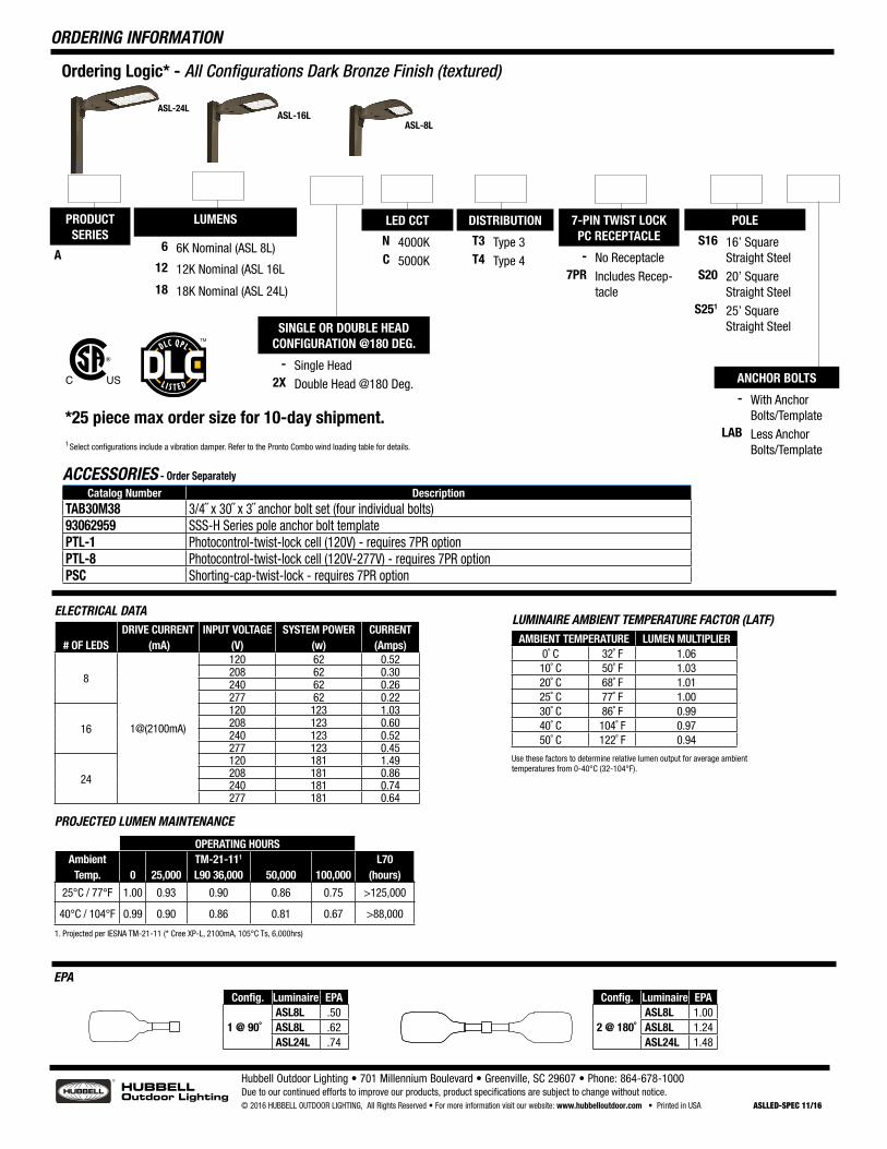
ORDERING INFORMATION
PRODUCT SERIES
A
SINGLE OR DOUBLE HEAD CONFIGURATION @180 DEG.
- Single Head2X Double Head @180 Deg.
LED CCT
N 4000KC 5000K
DISTRIBUTION
T3 Type 3T4 Type 4
7-PIN TWIST LOCK PC RECEPTACLE
- No Receptacle7PR Includes Recep-
tacle
ANCHOR BOLTS
- With Anchor Bolts/Template
LAB Less Anchor Bolts/Template
POLE
S16 16’ Square Straight Steel
S20 20’ Square Straight Steel
S251 25’ Square Straight Steel
LUMENS
6 6K Nominal (ASL 8L)
12 12K Nominal (ASL 16L
18 18K Nominal (ASL 24L)
ACCESSORIES - Order Separately
Catalog Number DescriptionTAB30M38 3/4˝ x 30˝ x 3˝ anchor bolt set (four individual bolts) 93062959 SSS-H Series pole anchor bolt templatePTL-1 Photocontrol-twist-lock cell (120V) - requires 7PR optionPTL-8 Photocontrol-twist-lock cell (120V-277V) - requires 7PR optionPSC Shorting-cap-twist-lock - requires 7PR option
*25 piece max order size for 10-day shipment.
# OF LEDSDRIVE CURRENT
(mA)INPUT VOLTAGE
(V)SYSTEM POWER
(w)CURRENT(Amps)
8
1@(2100mA)
120 62 0.52208 62 0.30240 62 0.26277 62 0.22
16
120 123 1.03208 123 0.60240 123 0.52277 123 0.45
24
120 181 1.49208 181 0.86240 181 0.74277 181 0.64
ELECTRICAL DATALUMINAIRE AMBIENT TEMPERATURE FACTOR (LATF)
PROJECTED LUMEN MAINTENANCE
AMBIENT TEMPERATURE LUMEN MULTIPLIER0˚ C 32˚ F 1.0610˚ C 50˚ F 1.0320˚ C 68˚ F 1.0125˚ C 77˚ F 1.0030˚ C 86˚ F 0.9940˚ C 104˚ F 0.9750˚ C 122˚ F 0.94
Use these factors to determine relative lumen output for average ambient temperatures from 0-40°C (32-104°F).
OPERATING HOURSAmbient
Temp. 0 25,000TM-21-111 L90 36,000 50,000 100,000
L70(hours)
25°C / 77°F 1.00 0.93 0.90 0.86 0.75 >125,000
40°C / 104°F 0.99 0.90 0.86 0.81 0.67 >88,000
1. Projected per IESNA TM-21-11 (* Cree XP-L, 2100mA, 105°C Ts, 6,000hrs)
EPA
Config. Luminaire EPA
1 @ 90˚ ASL8L .50 ASL8L .62 ASL24L .74
Config. Luminaire EPA
2 @ 180˚ ASL8L 1.00 ASL8L 1.24 ASL24L 1.48
Ordering Logic* - All Configurations Dark Bronze Finish (textured)
1 Select configurations include a vibration damper. Refer to the Pronto Combo wind loading table for details.
Hubbell Outdoor Lighting • 701 Millennium Boulevard • Greenville, SC 29607 • Phone: 864-678-1000Due to our continued efforts to improve our products, product specifications are subject to change without notice.© 2016 HUBBELL OUTDOOR LIGHTING, All Rights Reserved • For more information visit our website: www.hubbelloutdoor.com • Printed in USA ASLLED-SPEC 11/16
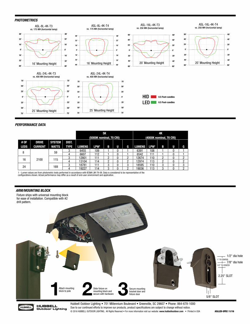
PHOTOMETRICS
32‘
0’
16‘
32‘
16‘
0’
48‘
32‘
16‘
32‘
16‘
48‘
48‘ 48‘
32‘
0’
16‘
32‘
16‘
0’
48‘
32‘
16‘
32‘
16‘
48‘
48‘ 48‘
ASL-8L-4K-T3vs. 175 MH (horizontal lamp)
ASL-8L-4K-T4vs. 175 MH (horizontal lamp)
40‘
20‘
40‘
20‘
60‘
40‘
20‘
40‘
20‘
60‘
60‘ 60‘
0‘ 0‘
40‘
20‘
40‘
20‘
60‘
40‘
20‘
40‘
20‘
60‘
60‘ 60‘
0‘ 0‘
ASL-16L-4K-T3vs. 250 MH (horizontal lamp)
ASL-16L-4K-T4vs. 250 MH (horizontal lamp)
50‘
0‘
25‘
50‘
25‘
0‘
75‘
50‘
25‘
50‘
25‘
75‘
75‘ 75‘
50‘
0‘
25‘
50‘
25‘
0‘
75‘
50‘
25‘
50‘
25‘
75‘
75‘ 75‘
ASL-24L-4K-T3vs. 400 MH (horizontal lamp)
ASL-24L-4K-T4vs. 400 MH (horizontal lamp)
1 2 3Attach mountingblock to pole
Slide fixture onmounting block andsecure with hardware
Secure mountingbracket door andfixture door
ARM/MOUNTING BLOCK Fixture ships with universal mounting block for ease of installation. Compatible with #2 drill pattern.
2.25" SLOT
7/8" dia hole
1/2" dia hole
5/8" SLOT
1/2" TO CENTER
1" TO CENTER
HIDLED
0.5 Foot-candles
0.5 Foot-candles
16´ Mounting Height 16´ Mounting Height 20´ Mounting Height 20´ Mounting Height
25´ Mounting Height 25´ Mounting Height
5K(5000K nominal, 70 CRI)
4K(4000K nominal, 70 CRI)
# OF LEDS
DRIVE CURRENT
SYSTEM WATTS
DIST.TYPE LUMENS LPW1 B U G LUMENS LPW1 B U G
88
2100
59 3 6455 109 1 0 1 6391 108 1 0 14 6607 112 1 0 1 6542 111 1 0 1
16 115 3 12801 111 2 0 2 12674 110 2 0 24 13104 114 2 0 2 12974 113 2 0 2
24 169 3 18781 111 3 0 3 18595 110 3 0 34 19227 114 3 0 2 19036 113 3 0 2
1 - Lumen values are from photometric tests performed in accordance with IESNA LM-79-08. Data is considered to be representative of the configurations shown. Actual performance may differ as a result of end-user environment and application.
PERFORMANCE DATA
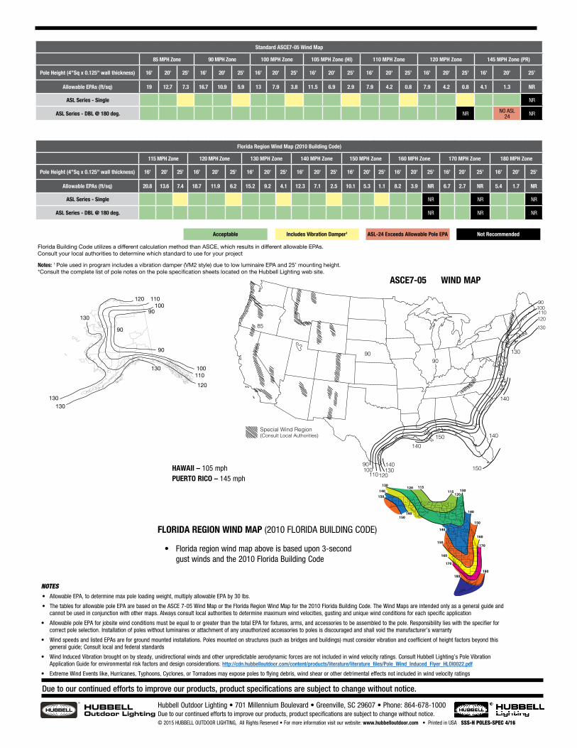
NOTES• Allowable EPA, to determine max pole loading weight, multiply allowable EPA by 30 lbs.
• The tables for allowable pole EPA are based on the ASCE 7-05 Wind Map or the Florida Region Wind Map for the 2010 Florida Building Code. The Wind Maps are intended only as a general guide and cannot be used in conjunction with other maps. Always consult local authorities to determine maximum wind velocities, gusting and unique wind conditions for each specific application
• Allowable pole EPA for jobsite wind conditions must be equal to or greater than the total EPA for fixtures, arms, and accessories to be assembled to the pole. Responsibility lies with the specifier for correct pole selection. Installation of poles without luminaires or attachment of any unauthorized accessories to poles is discouraged and shall void the manufacturer’s warranty
• Wind speeds and listed EPAs are for ground mounted installations. Poles mounted on structures (such as bridges and buildings) must consider vibration and coefficient of height factors beyond this general guide; Consult local and federal standards
• Wind Induced Vibration brought on by steady, unidirectional winds and other unpredictable aerodynamic forces are not included in wind velocity ratings. Consult Hubbell Lighting’s Pole Vibration Application Guide for environmental risk factors and design considerations. http://cdn.hubbelloutdoor.com/content/products/literature/literature_files/Pole_Wind_Induced_Flyer_HLOI0022.pdf
• Extreme Wind Events like, Hurricanes, Typhoons, Cyclones, or Tornadoes may expose poles to flying debris, wind shear or other detrimental effects not included in wind velocity ratings
Hubbell Outdoor Lighting • 701 Millennium Boulevard • Greenville, SC 29607 • Phone: 864-678-1000Due to our continued efforts to improve our products, product specifications are subject to change without notice.© 2015 HUBBELL OUTDOOR LIGHTING, All Rights Reserved • For more information visit our website: www.hubbelloutdoor.com • Printed in USA SSS-H POLES-SPEC 4/16
Due to our continued efforts to improve our products, product specifications are subject to change without notice.
Standard ASCE7-05 Wind Map
85 MPH Zone 90 MPH Zone 100 MPH Zone 105 MPH Zone (HI) 110 MPH Zone 120 MPH Zone 145 MPH Zone (PR)
Pole Height (4”Sq x 0.125” wall thickness) 16’ 20’ 25’ 16’ 20’ 25’ 16’ 20’ 25’ 16’ 20’ 25’ 16’ 20’ 25’ 16’ 20’ 25’ 16’ 20’ 25’
Allowable EPAs (ft/sq) 19 12.7 7.3 16.7 10.9 5.9 13 7.9 3.8 11.5 6.9 2.9 7.9 4.2 0.8 7.9 4.2 0.8 4.1 1.3 NR
ASL Series - Single NR
ASL Series - DBL @ 180 deg. NR NO ASL 24 NR
Florida Region Wind Map (2010 Building Code)
115 MPH Zone 120 MPH Zone 130 MPH Zone 140 MPH Zone 150 MPH Zone 160 MPH Zone 170 MPH Zone 180 MPH Zone
Pole Height (4”Sq x 0.125” wall thickness) 16’ 20’ 25’ 16’ 20’ 25’ 16’ 20’ 25’ 16’ 20’ 25’ 16’ 20’ 25’ 16’ 20’ 25’ 16’ 20’ 25’ 16’ 20’ 25’
Allowable EPAs (ft/sq) 20.8 13.6 7.4 18.7 11.9 6.2 15.2 9.2 4.1 12.3 7.1 2.5 10.1 5.3 1.1 8.2 3.9 NR 6.7 2.7 NR 5.4 1.7 NR
ASL Series - Single NR NR NR
ASL Series - DBL @ 180 deg. NR NR NR
Acceptable Includes Vibration Damper1 ASL-24 Exceeds Allowable Pole EPA Not Recommended
Notes: 1 Pole used in program includes a vibration damper (VM2 style) due to low luminaire EPA and 25’ mounting height. *Consult the complete list of pole notes on the pole specification sheets located on the Hubbell Lighting web site.
Florida Building Code utilizes a different calculation method than ASCE, which results in different allowable EPAs. Consult your local authorities to determine which standard to use for your project
ASCE7-05 WIND MAP
180180
170
170
160
160150
150
140
140140150
140150
130120 115
115120
130
FLORIDA REGION WIND MAP (2010 FLORIDA BUILDING CODE)
HAWAII – 105 mph PUERTO RICO – 145 mph
NOTES:• Values are based on 50 year mean recurrence interval 30’
above grade.• Hawaii has an 105 mph wind velocity.• Puerto Rico has a 125 mph wind velocity.• Caution must be exercised in determining wind velocities
in special wind areas such as:Mountainous RegionsAreas surrounding the Great Lakes or other large bodies of water or open land.Areas subject to extreme wind conditions, such as hurricanes, typhoons, cyclones, and tornadoes.Areas adjacent to airports.Any specific area with a known or suspected abnormally high intermittent wind condition caused by geography, adjacent structures, or other specific local conditions that may not be recorded in National Weather Service records.
• Allowable pole EPA for jobsite wind conditions must be equal to or greater than fixture EPA. Responsibility lies with the specifier for correct pole selection based on AASHTO wind map and job location.
• The Wind Map is intended only as a general guide. Always consult local authorities to determine maximum wind velocities, gusting and unique wind conditions for each specific application.
• CAUTION: Wind speeds and listed EPAs are for ground mounted installations. Poles mounted on structures (such as bridges and buildings) must consider vibration and coefficient of height factors beyond this general guide. Consult AASHTO standards.
• Extreme Wind Events: Hurricanes, Typhoons, Cyclones, or Tornadoes expose poles to flying debris, wind shear, and other unpredictable aerodynamic forces not indicated by the wind velocity ratings.
• Pole Strength Limited Warranty: Standard, unmodified Kim lighting Poles installed as recommended, undamaged by corrosion, or lack of maintenance, shall withstand steady wind conditions as provided on page 2 (Allowable Pole EPA). Installation of poles without luminaires, or attachment of any unauthorized accessories to poles shall void this warranty.
85
90
90100110120130
130
140
140
140
150
150
140130
12011010090
Special Wind Region(Consult Local Authorities)
90Wind Map
United States and Canada
• Florida region wind map above is based upon 3-second gust winds and the 2010 Florida Building Code
120 110100
90
90
90
100110120
130
130130
130