Embed Size (px)
DESCRIPTION
Airman Pro
Citation preview

INSTRUCTIONAL MANUAL
MOBILE GENERATORS
SDG25S-6A7, SDG45S-6A6, SDG65S-6A6, SDG100S-6A6
MMD Equipment Inc. 121 High Hill Road
Swedesboro, NJ 08085 Tel: (800) 433-1382 Fax: (856) 467-5235
www.mmdequipment.com
Preface
◆ This manual explains and illustrates proper handling of the unit, method of daily inspection and
maintenance to enhance the performance of AIRMAN’s generators.
◆ In order to use a machine safely, people with sufficient knowledge and sufficient technology need to deal
with it. ◆ Before operating the unit, read the manual carefully, fully understand its operation and maintenance
requirement. Maintain “SAFETY OPERATION AND PROPER MAINTENANCE OF THE UNIT”.
Be sure to follow safety warnings and cautions given in the manual. Unsafe operation could cause serious injury or death.
◆ For details of handling, maintenance and safety of the engine, see the Engine Operation Manual. ◆ Keep the manual available at all times for the operator or safety supervisor. ◆ If the manual is lost or damaged, place an order with your dealer for another copy. ◆ Be sure that the manual is included with the unit when it is handed over to another user. ◆ There may be some inconsistency in detail between the manual and the actual machine due to
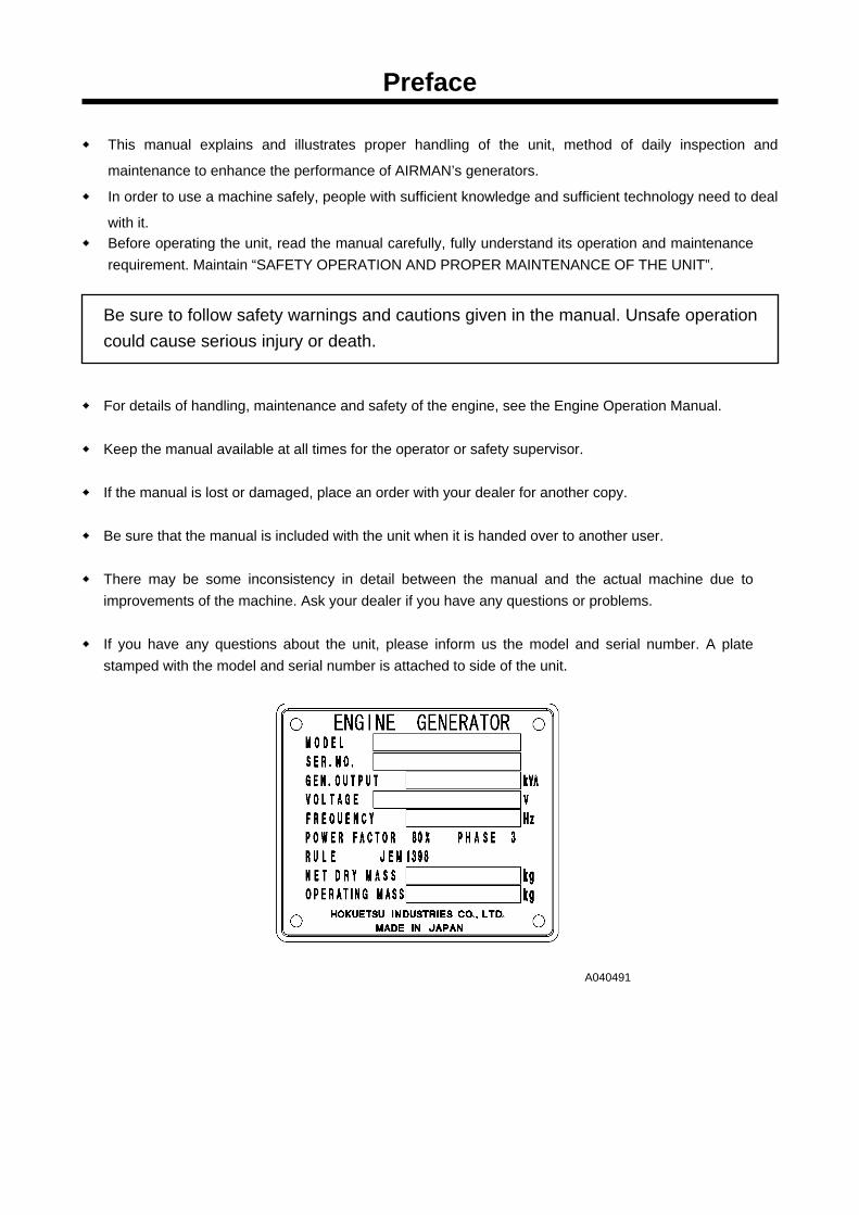
improvements of the machine. Ask your dealer if you have any questions or problems. ◆ If you have any questions about the unit, please inform us the model and serial number. A plate
stamped with the model and serial number is attached to side of the unit.
A040491
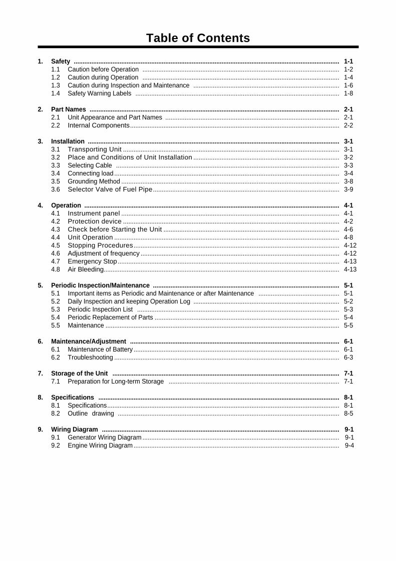
Table of Contents
1. Safety ....................................................................................................................................................... 1-1 1.1 Caution before Operation ................................................................................................................ 1-2 1.2 Caution during Operation ................................................................................................................ 1-4 1.3 Caution during Inspection and Maintenance ................................................................................... 1-6 1.4 Safety Warning Labels .................................................................................................................... 1-8
2. Part Names .............................................................................................................................................. 2-1
2.1 Unit Appearance and Part Names ................................................................................................... 2-1 2.2 Internal Components....................................................................................................................... 2-2
3. Installation ............................................................................................................................................... 3-1
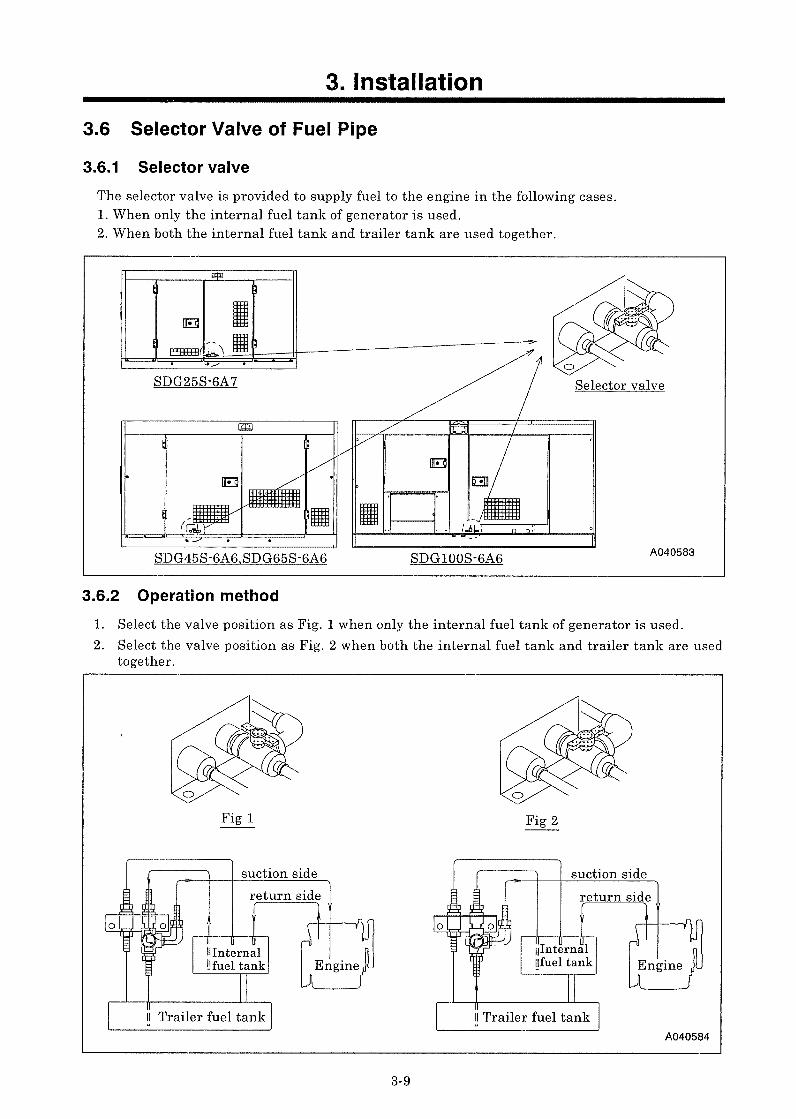
3.1 Transporting Unit ........................................................................................................................... 3-1 3.2 Place and Conditions of Unit Installation ................................................................................... 3-2 3.3 Selecting Cable ............................................................................................................................... 3-3 3.4 Connecting load ................................................................................................................................ 3-4 3.5 Grounding Method ............................................................................................................................ 3-8 3.6 Selector Valve of Fuel Pipe.......................................................................................................... 3-9
4. Operation ................................................................................................................................................. 4-1
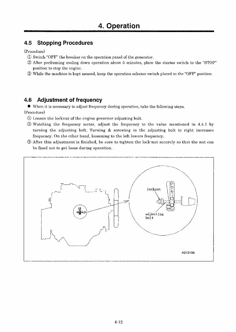
4.1 Instrument panel ............................................................................................................................ 4-1 4.2 Protection device ........................................................................................................................... 4-2 4.3 Check before Starting the Unit .................................................................................................... 4-6 4.4 Unit Operation ................................................................................................................................ 4-8 4.5 Stopping Procedures..................................................................................................................... 4-12 4.6 Adjustment of frequency ................................................................................................................. 4-12 4.7 Emergency Stop .............................................................................................................................. 4-13 4.8 Air Bleeding...................................................................................................................................... 4-13
5. Periodic Inspection/Maintenance .......................................................................................................... 5-1
5.1 Important items as Periodic and Maintenance or after Maintenance .............................................. 5-1 5.2 Daily Inspection and keeping Operation Log ................................................................................... 5-2 5.3 Periodic Inspection List ................................................................................................................... 5-3 5.4 Periodic Replacement of Parts ......................................................................................................... 5-4 5.5 Maintenance ..................................................................................................................................... 5-5
6. Maintenance/Adjustment ....................................................................................................................... 6-1
6.1 Maintenance of Battery ..................................................................................................................... 6-1 6.2 Troubleshooting ................................................................................................................................ 6-3
7. Storage of the Unit ................................................................................................................................. 7-1
7.1 Preparation for Long-term Storage ................................................................................................. 7-1 8. Specifications ......................................................................................................................................... 8-1
8.1 Specifications.................................................................................................................................... 8-1 8.2 Outline drawing .............................................................................................................................. 8-5
9. Wiring Diagram ....................................................................................................................................... 1 9-1
9.1 Generator Wiring Diagram ................................................................................................................ . 9-1 9.2 Engine Wiring Diagram ..................................................................................................................... . 9-4
1.Safety
1-1
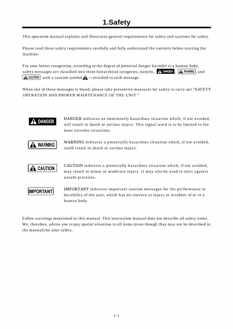
This operation manual explains and illustrates general requirements for safety and cautions for safety. Please read these safety requirements carefully and fully understand the contents before starting the machine. For your better recognition, according to the degree of potential danger harmful to a human body, safety messages are classified into three hierarchical categories, namely, , , and
with a caution symbol -attached to each message. When one of these messages is found, please take preventive measures for safety to carry out “SAFETY OPERATION AND PROPER MAINTENANCE OF THE UNIT ”.
DANGER indicates an imminently hazardous situation which, if not avoided, will result in death or serious injury. This signal word is to be limited to the most extreme situations. WARNING indicates a potentially hazardous situation which, if not avoided, could result in death or serious injury. CAUTION indicates a potentially hazardous situation which, if not avoided, may result in minor or moderate injury. It may also be used to alert against unsafe practices. IMPORTANT indicates important caution messages for the performance or durability of the unit, which has no concern to injury or accident of or to a human body.
Follow warnings mentioned in this manual. This instruction manual does not describe all safety items. We, therefore, advise you to pay special attention to all items (even though they may not be described in the manual) for your safety.
1.Safety
1-2
1.1 Caution before Operation
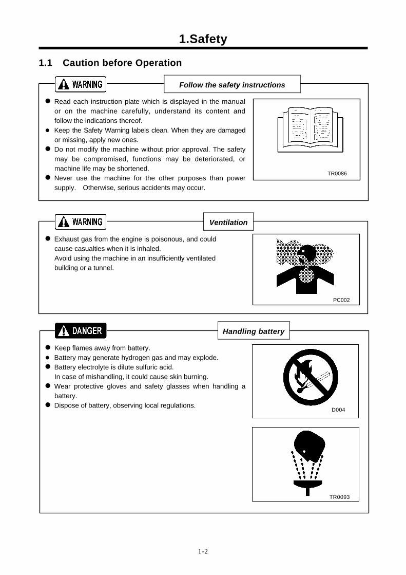
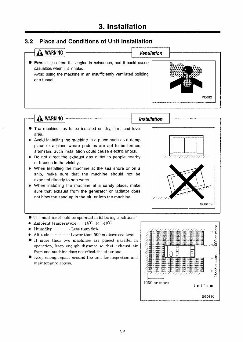
Ventilation Exhaust gas from the engine is poisonous, and could cause casualties when it is inhaled. Avoid using the machine in an insufficiently ventilated building or a tunnel.
PC002
Follow the safety instructions Read each instruction plate which is displayed in the manual or on the machine carefully, understand its content and follow the indications thereof. Keep the Safety Warning labels clean. When they are damaged
or missing, apply new ones. Do not modify the machine without prior approval. The safety may be compromised, functions may be deteriorated, or machine life may be shortened. Never use the machine for the other purposes than power supply. Otherwise, serious accidents may occur.
TR0086
Handling battery Keep flames away from battery. Battery may generate hydrogen gas and may explode. Battery electrolyte is dilute sulfuric acid. In case of mishandling, it could cause skin burning. Wear protective gloves and safety glasses when handling a battery. Dispose of battery, observing local regulations.
D004
TR0093
1.Safety
1-3
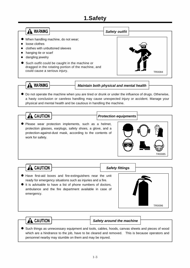
Safety outfit When handling machine, do not wear; loose clothes clothes with unbuttoned sleeves hanging tie or scarf dangling jewelry
Such outfit could be caught in the machine or dragged in the rotating portion of the machine, and could cause a serious injury.
Maintain both physical and mental health Do not operate the machine when you are tired or drunk or under the influence of drugs. Otherwise, a hasty conclusion or careless handling may cause unexpected injury or accident. Manage your physical and mental health and be cautious in handling the machine.
Protection equipments
Please wear protection implements, such as a helmet, protection glasses, earplugs, safety shoes, a glove, and a protection-against-dust mask, according to the contents of work for safety.
Safety fittings
Have first-aid boxes and fire-extinguishers near the unit ready for emergency situations such as injuries and a fire. It is advisable to have a list of phone numbers of doctors, ambulance and the fire department available in case of emergency.
Safety around the machine
Such things as unnecessary equipment and tools, cables, hoods, canvas sheets and pieces of wood which are a hindrance to the job, have to be cleared and removed. This is because operators and personnel nearby may stumble on them and may be injured.
TR0084
TR0085
TR0096
1.Safety
1-4
1.2 Caution during Operation
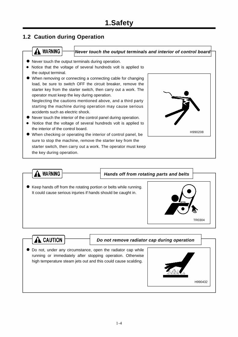
Never touch the output terminals and interior of control board Never touch the output terminals during operation. Notice that the voltage of several hundreds volt is applied to
the output terminal. When removing or connecting a connecting cable for changing load, be sure to switch OFF the circuit breaker, remove the starter key from the starter switch, then carry out a work. The operator must keep the key during operation. Neglecting the cautions mentioned above, and a third party starting the machine during operation may cause serious accidents such as electric shock. Never touch the interior of the control panel during operation. Notice that the voltage of several hundreds volt is applied to
the interior of the control board. When checking or operating the interior of control panel, be sure to stop the machine, remove the starter key from the starter switch, then carry out a work. The operator must keep the key during operation.
H990208
Hands off from rotating parts and belts Keep hands off from the rotating portion or belts while running. It could cause serious injuries if hands should be caught in.
TR0304
Do not remove radiator cap during operation
Do not, under any circumstance, open the radiator cap while running or immediately after stopping operation. Otherwise high temperature steam jets out and this could cause scalding.
H990432
1.Safety
1-5
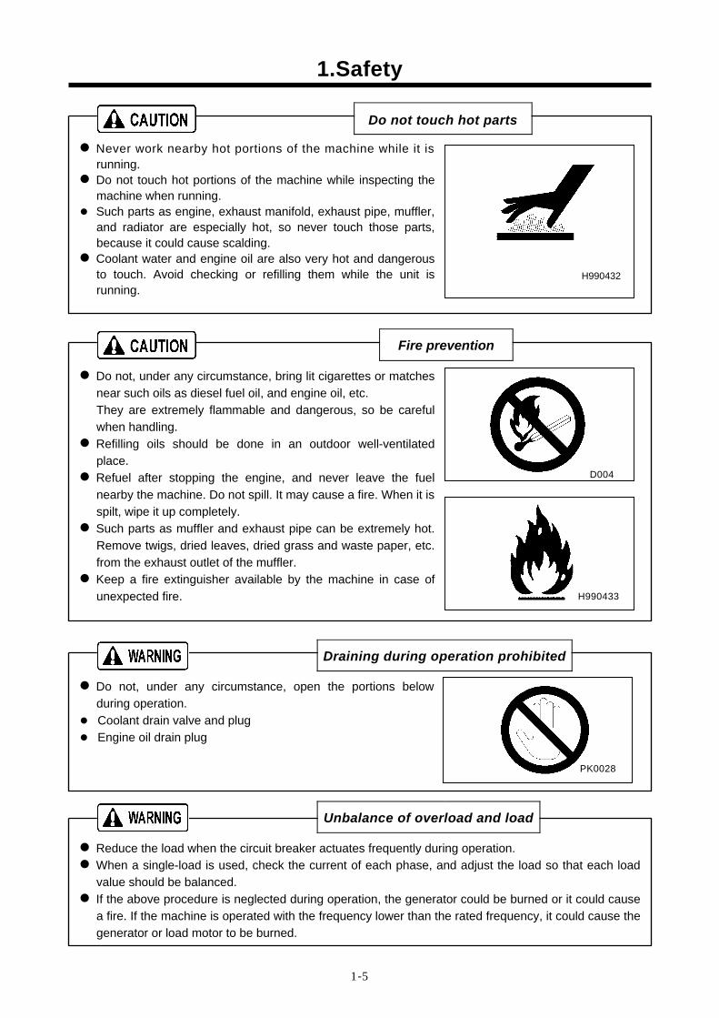
Do not touch hot parts
Never work nearby hot portions of the machine while it is running. Do not touch hot portions of the machine while inspecting the machine when running. Such parts as engine, exhaust manifold, exhaust pipe, muffler,
and radiator are especially hot, so never touch those parts, because it could cause scalding. Coolant water and engine oil are also very hot and dangerous to touch. Avoid checking or refilling them while the unit is running.
H990432
Fire prevention
Do not, under any circumstance, bring lit cigarettes or matches near such oils as diesel fuel oil, and engine oil, etc. They are extremely flammable and dangerous, so be careful when handling. Refilling oils should be done in an outdoor well-ventilated place. Refuel after stopping the engine, and never leave the fuel nearby the machine. Do not spill. It may cause a fire. When it is spilt, wipe it up completely. Such parts as muffler and exhaust pipe can be extremely hot. Remove twigs, dried leaves, dried grass and waste paper, etc. from the exhaust outlet of the muffler. Keep a fire extinguisher available by the machine in case of unexpected fire.
D004
Draining during operation prohibited Do not, under any circumstance, open the portions below during operation. Coolant drain valve and plug Engine oil drain plug
Unbalance of overload and load Reduce the load when the circuit breaker actuates frequently during operation. When a single-load is used, check the current of each phase, and adjust the load so that each load value should be balanced. If the above procedure is neglected during operation, the generator could be burned or it could cause a fire. If the machine is operated with the frequency lower than the rated frequency, it could cause the generator or load motor to be burned.
H990433
PK0028
1.Safety
1-6
1.3 Cautions during Inspection and Maintenance
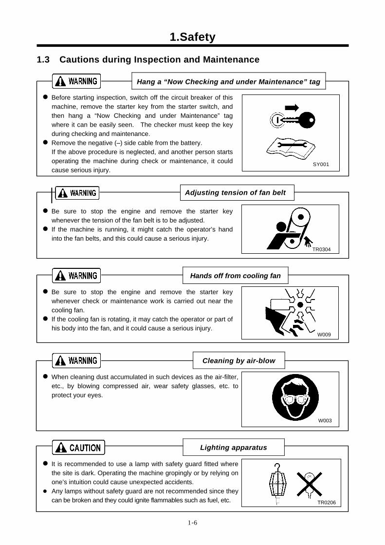
Hang a “Now Checking and under Maintenance” tag Before starting inspection, switch off the circuit breaker of this machine, remove the starter key from the starter switch, and then hang a “Now Checking and under Maintenance” tag where it can be easily seen. The checker must keep the key during checking and maintenance. Remove the negative (–) side cable from the battery. If the above procedure is neglected, and another person starts operating the machine during check or maintenance, it could cause serious injury.
Be sure to stop the engine and remove the starter key whenever the tension of the fan belt is to be adjusted. If the machine is running, it might catch the operator’s hand into the fan belts, and this could cause a serious injury.
Hands off from cooling fan Be sure to stop the engine and remove the starter key whenever check or maintenance work is carried out near the cooling fan. If the cooling fan is rotating, it may catch the operator or part of his body into the fan, and it could cause a serious injury.
Cleaning by air-blow When cleaning dust accumulated in such devices as the air-filter, etc., by blowing compressed air, wear safety glasses, etc. to protect your eyes.
Lighting apparatus
It is recommended to use a lamp with safety guard fitted where the site is dark. Operating the machine gropingly or by relying on one’s intuition could cause unexpected accidents. Any lamps without safety guard are not recommended since they
can be broken and they could ignite flammables such as fuel, etc.
W009
TR0206
W003
TR0304
SY001
Adjusting tension of fan belt
1.Safety
1-7
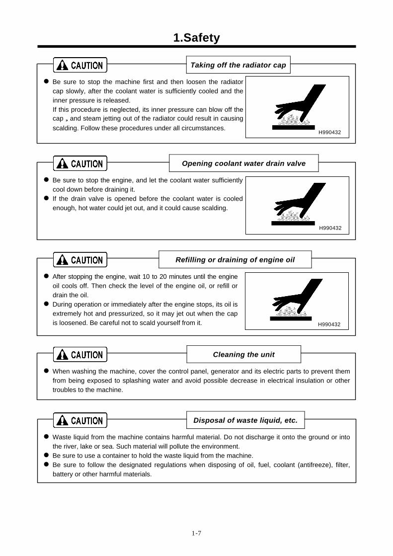
Taking off the radiator cap
Be sure to stop the machine first and then loosen the radiator cap slowly, after the coolant water is sufficiently cooled and the inner pressure is released. If this procedure is neglected, its inner pressure can blow off the cap,and steam jetting out of the radiator could result in causing scalding. Follow these procedures under all circumstances.
Opening coolant water drain valve
Be sure to stop the engine, and let the coolant water sufficiently cool down before draining it. If the drain valve is opened before the coolant water is cooled enough, hot water could jet out, and it could cause scalding.
Refilling or draining of engine oil
After stopping the engine, wait 10 to 20 minutes until the engine oil cools off. Then check the level of the engine oil, or refill or drain the oil. During operation or immediately after the engine stops, its oil is extremely hot and pressurized, so it may jet out when the cap is loosened. Be careful not to scald yourself from it.
Cleaning the unit
When washing the machine, cover the control panel, generator and its electric parts to prevent them from being exposed to splashing water and avoid possible decrease in electrical insulation or other troubles to the machine.
Disposal of waste liquid, etc.
Waste liquid from the machine contains harmful material. Do not discharge it onto the ground or into the river, lake or sea. Such material will pollute the environment. Be sure to use a container to hold the waste liquid from the machine. Be sure to follow the designated regulations when disposing of oil, fuel, coolant (antifreeze), filter, battery or other harmful materials.
H990432
H990432
H990432
1.Safety
1-8
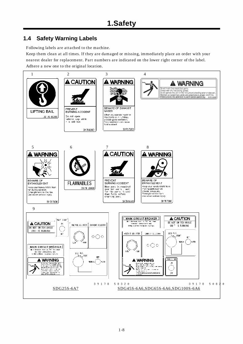
1.4 Safety Warning Labels Following labels are attached to the machine. Keep them clean at all times. If they are damaged or missing, immediately place an order with your nearest dealer for replacement. Part numbers are indicated on the lower right corner of the label. Adhere a new one to the original location.
1 2 3 4
5 6 7 8
9
39178 50820
SDG45S-6A6,SDG65S-6A6,SDG100S-6A6 39178 58320
SDG25S-6A7
1.Safety
1-9
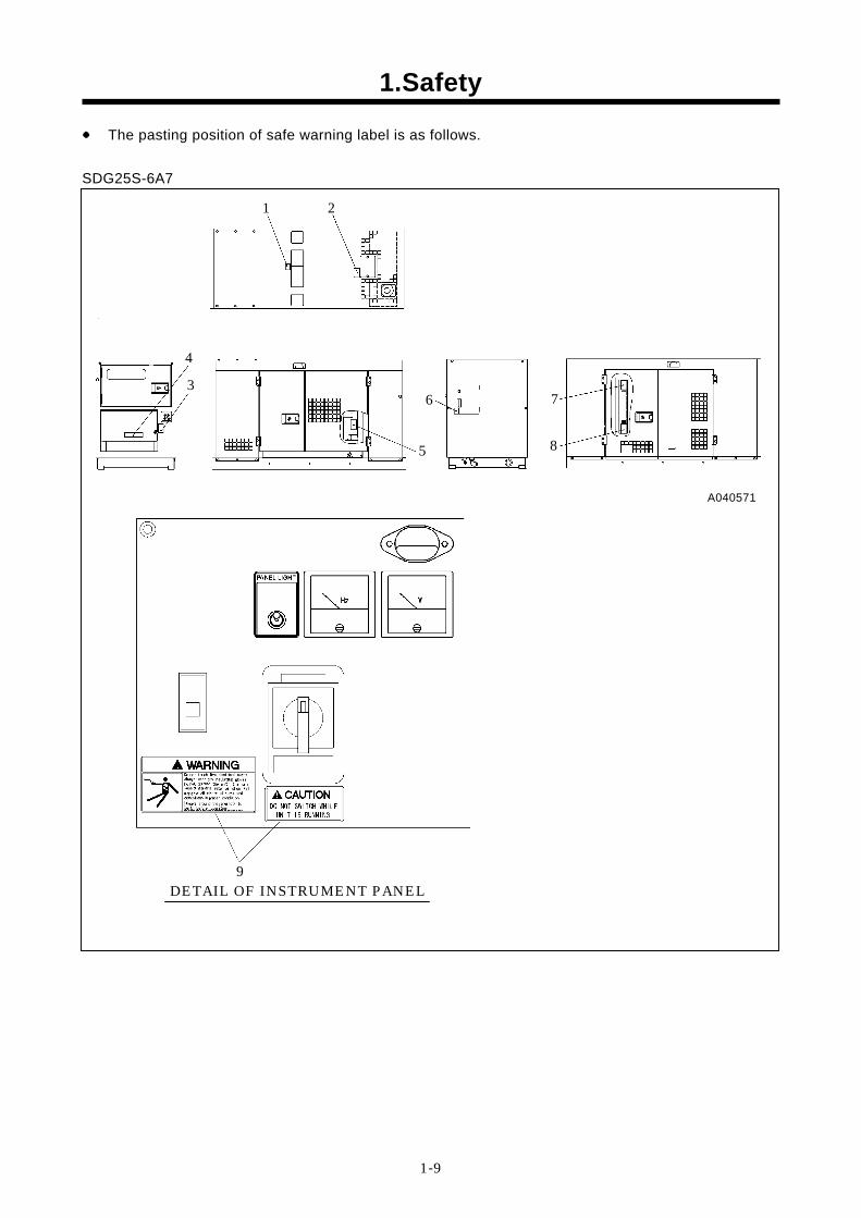
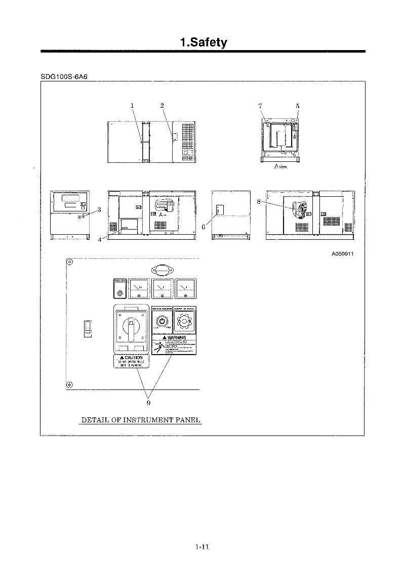
● The pasting position of safe warning label is as follows. SDG25S-6A7
6
2
3
5
4
7
8
1
A040571
DETAIL OF INSTRUMENT PANEL 9
1.Safety
1-10
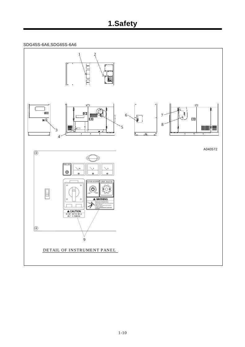
SDG45S-6A6,SDG65S-6A6
6
2
3 5
4
7
8
1
DETAIL OF INSTRUMENT PANEL
9
A040572
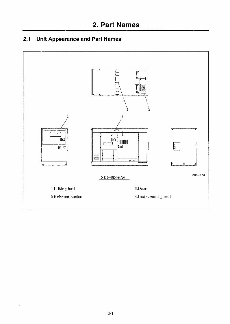
2. Part Names
2-2
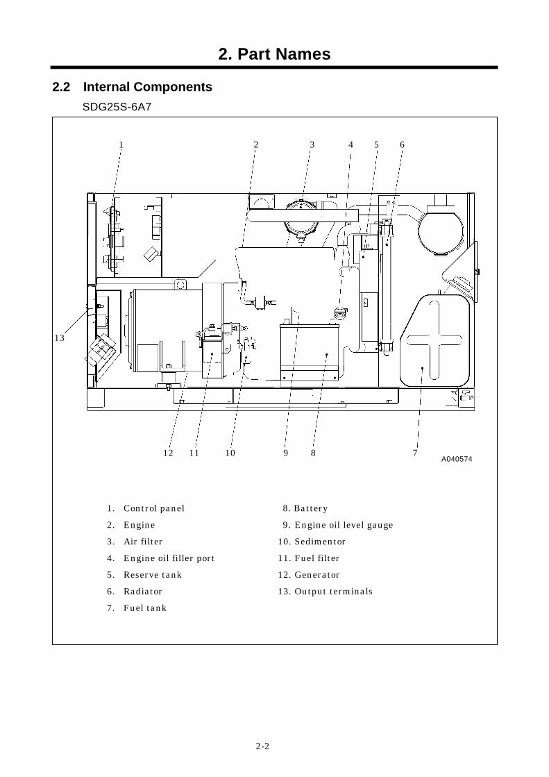
2.2 Internal Components SDG25S-6A7
1 2 3 4 5 6
12 11 10 9 8 7
13
1. Control panel 2. Engine 3. Air filter 4. Engine oil filler port 5. Reserve tank 6. Radiator 7. Fuel tank
8. Battery 9. Engine oil level gauge
10. Sedimentor 11. Fuel filter 12. Generator 13. Output terminals
A040574
2. Part Names
2-4
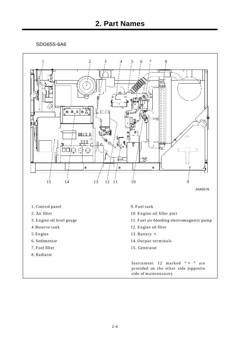
SDG65S-6A6
1. Control panel 2. Air filter 3. Engine oil level gauge 4. Reserve tank 5. Engine 6. Sedimentor 7. Fuel filter 8. Radiator
9. Fuel tank 10. Engine oil filler port 11. Fuel air-bleeding electromagnetic pump 12. Engine oil filter 13. Battery ※ 14. Output terminals 15. Generator
A040576
1 2 3 4 5 6 7 8
15 14 13 12 11 10 9
Instrument 12 marked “ ※ ” areprovided on the other side (oppositeside of maintenance).
3. Installation
3-1
3.1 Transporting Unit
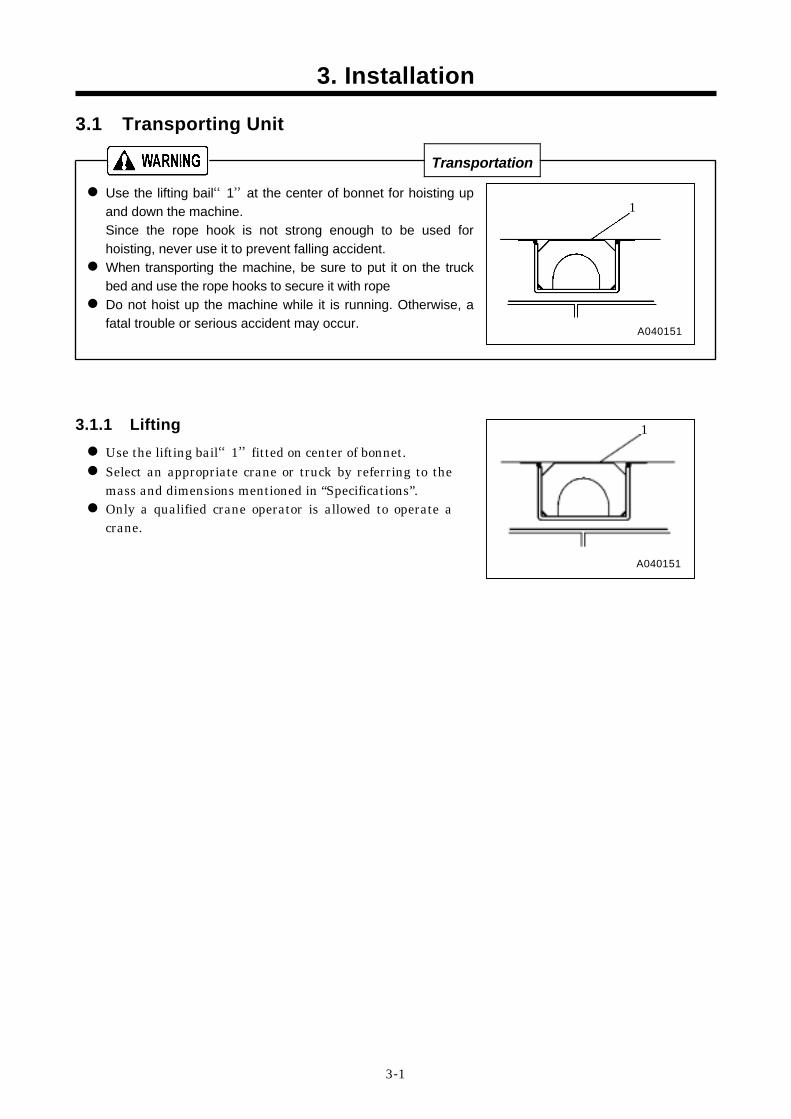
Transportation Use the lifting bail“1”at the center of bonnet for hoisting up and down the machine. Since the rope hook is not strong enough to be used for hoisting, never use it to prevent falling accident. When transporting the machine, be sure to put it on the truck bed and use the rope hooks to secure it with rope Do not hoist up the machine while it is running. Otherwise, a fatal trouble or serious accident may occur.
3.1.1 Lifting Use the lifting bail“1”fitted on center of bonnet. Select an appropriate crane or truck by referring to the mass and dimensions mentioned in “Specifications”. Only a qualified crane operator is allowed to operate a crane.
1
A040151
A040151
1
3. Installation
3-3
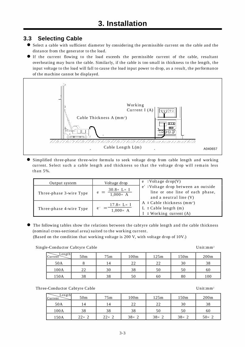
3.3 Selecting Cable Select a cable with sufficient diameter by considering the permissible current on the cable and the distance from the generator to the load. If the current flowing to the load exceeds the permissible current of the cable, resultant overheating may burn the cable. Similarly, if the cable is too small in thickness to the length, the input voltage to the load will fall to cause the load input power to drop, as a result, the performance of the machine cannot be displayed.
Simplified three-phase three-wire formula to seek voltage drop from cable length and working current. Select such a cable length and thickness so that the voltage drop will remain less than 5%.
Output system Voltage drop
Three-phase 3-wire Type
Three-phase 4-wire Type
The following tables show the relations between the cabtyre cable length and the cable thickness (nominal cross-sectional area) suited to the working current. (Based on the condition that working voltage is 200 V, with voltage drop of 10V.)
Single-Conductor Cabtyre Cable Unit:mm2
Three-Conductor Cabtyre Cable Unit:mm2
50m 75m 100m 125m 150m 200m 50A 8 14 22 22 30 38 100A 22 30 38 50 50 60 150A 38 38 50 60 80 100
50m 75m 100m 125m 150m 200m 50A 14 14 22 22 30 38 100A 38 38 38 50 50 60 150A 22×2 22×2 38×2 38×2 38×2 50×2
Cable Length L(m)
Length Current
Current
A040657
Length
Cable Thickness A (mm2)
Working Current I (A)
e :Voltage drop(V) e :Voltage drop between an outside
line or one line of each phase,and a neutral line (V)
A :Cable thickness (mm2) L :Cable length (m) I :Working current (A)
e = 1,000×A
e = 17.8×L×I1,000×A ’
’30.8×L×I
3. Installation
3-7
3.4.3 The Maximum Combined Simultaneous Power Consumption
Never exceed the maximum combined simultaneous power consumption.
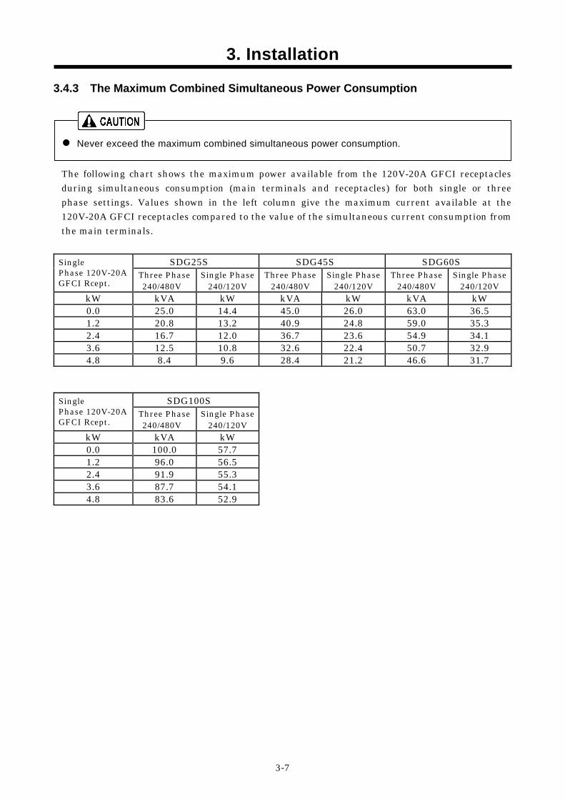
The following chart shows the maximum power available from the 120V-20A GFCI receptacles during simultaneous consumption (main terminals and receptacles) for both single or three phase settings. Values shown in the left column give the maximum current available at the 120V-20A GFCI receptacles compared to the value of the simultaneous current consumption from the main terminals.
SDG25S SDG45S SDG60S Single Phase 120V-20A GFCI Rcept.
Three Phase 240/480V
Single Phase 240/120V
Three Phase 240/480V
Single Phase 240/120V
Three Phase 240/480V
Single Phase 240/120V
kW kVA kW kVA kW kVA kW 0.0 25.0 14.4 45.0 26.0 63.0 36.5 1.2 20.8 13.2 40.9 24.8 59.0 35.3 2.4 16.7 12.0 36.7 23.6 54.9 34.1 3.6 12.5 10.8 32.6 22.4 50.7 32.9 4.8 8.4 9.6 28.4 21.2 46.6 31.7
SDG100S Single Phase 120V-20A GFCI Rcept.
Three Phase 240/480V
Single Phase 240/120V
kW kVA kW 0.0 100.0 57.7 1.2 96.0 56.5 2.4 91.9 55.3 3.6 87.7 54.1 4.8 83.6 52.9
4. Operation
4-4
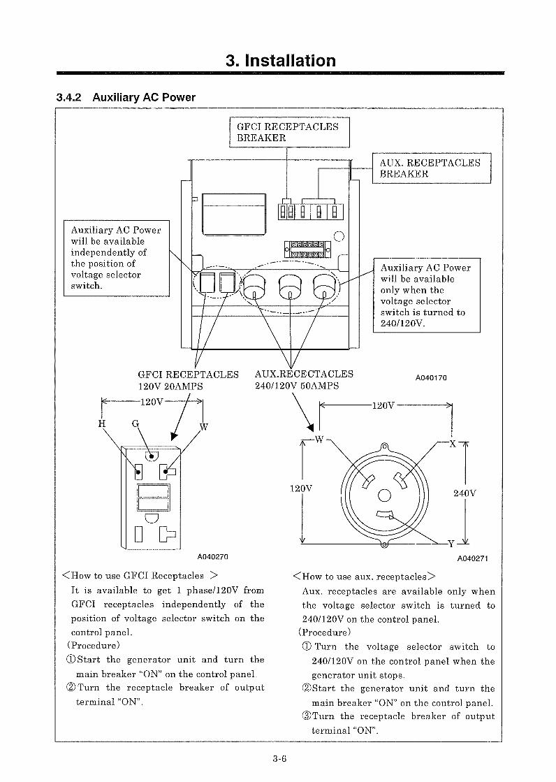
4.2.4 GFCI (Ground-fault circuit interrupter) Receptacles
Using the generator in rain, snow or near water can lead to death from electric shock. Keep the generator dry.
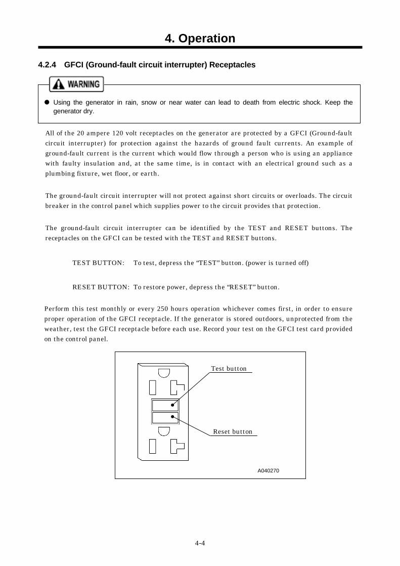
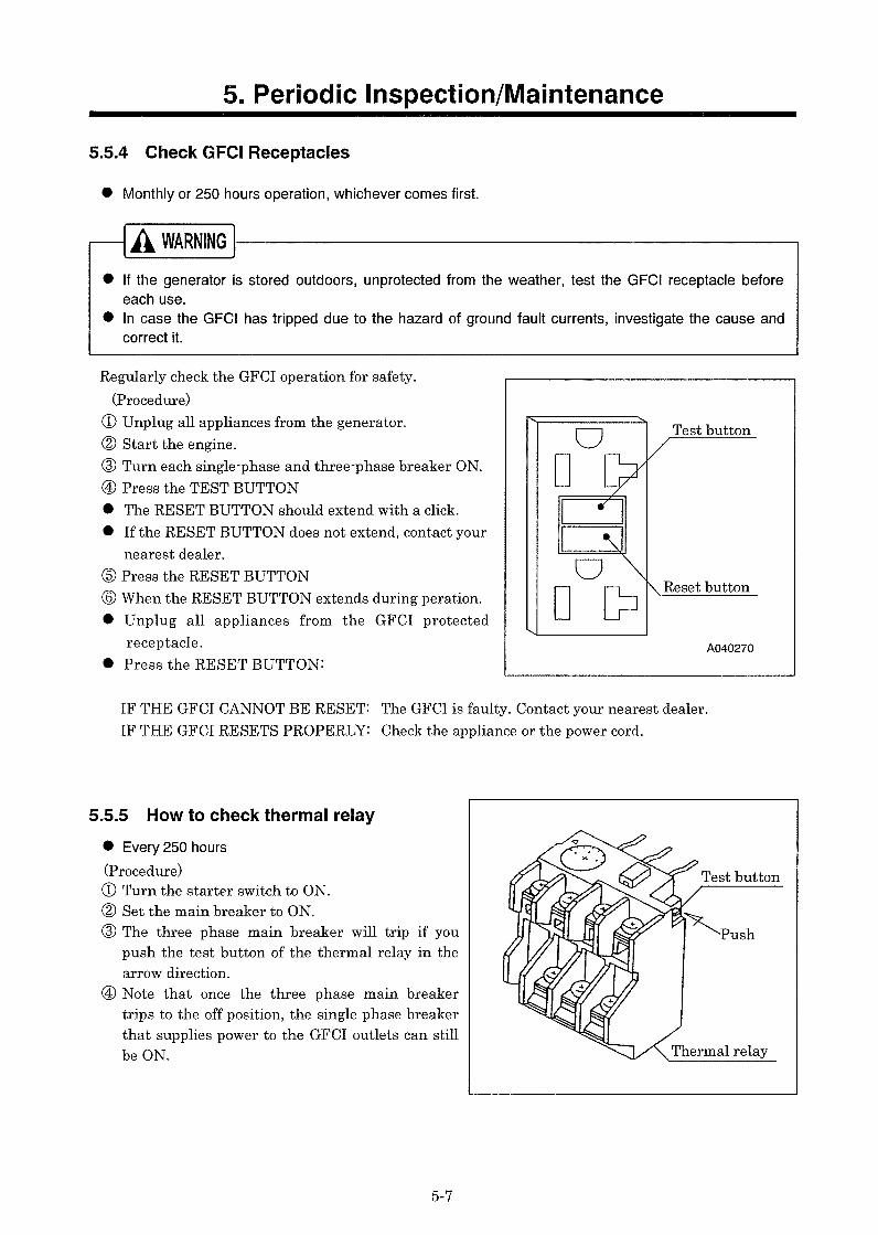
All of the 20 ampere 120 volt receptacles on the generator are protected by a GFCI (Ground-fault circuit interrupter) for protection against the hazards of ground fault currents. An example of ground-fault current is the current which would flow through a person who is using an appliance with faulty insulation and, at the same time, is in contact with an electrical ground such as a plumbing fixture, wet floor, or earth. The ground-fault circuit interrupter will not protect against short circuits or overloads. The circuit breaker in the control panel which supplies power to the circuit provides that protection. The ground-fault circuit interrupter can be identified by the TEST and RESET buttons. The receptacles on the GFCI can be tested with the TEST and RESET buttons.
TEST BUTTON: To test, depress the “TEST” button. (power is turned off)
RESET BUTTON: To restore power, depress the “RESET” button.
Perform this test monthly or every 250 hours operation whichever comes first, in order to ensure proper operation of the GFCI receptacle. If the generator is stored outdoors, unprotected from the weather, test the GFCI receptacle before each use. Record your test on the GFCI test card provided on the control panel.
A040270
Test button
Reset button
4. Operation
4-5
Reset
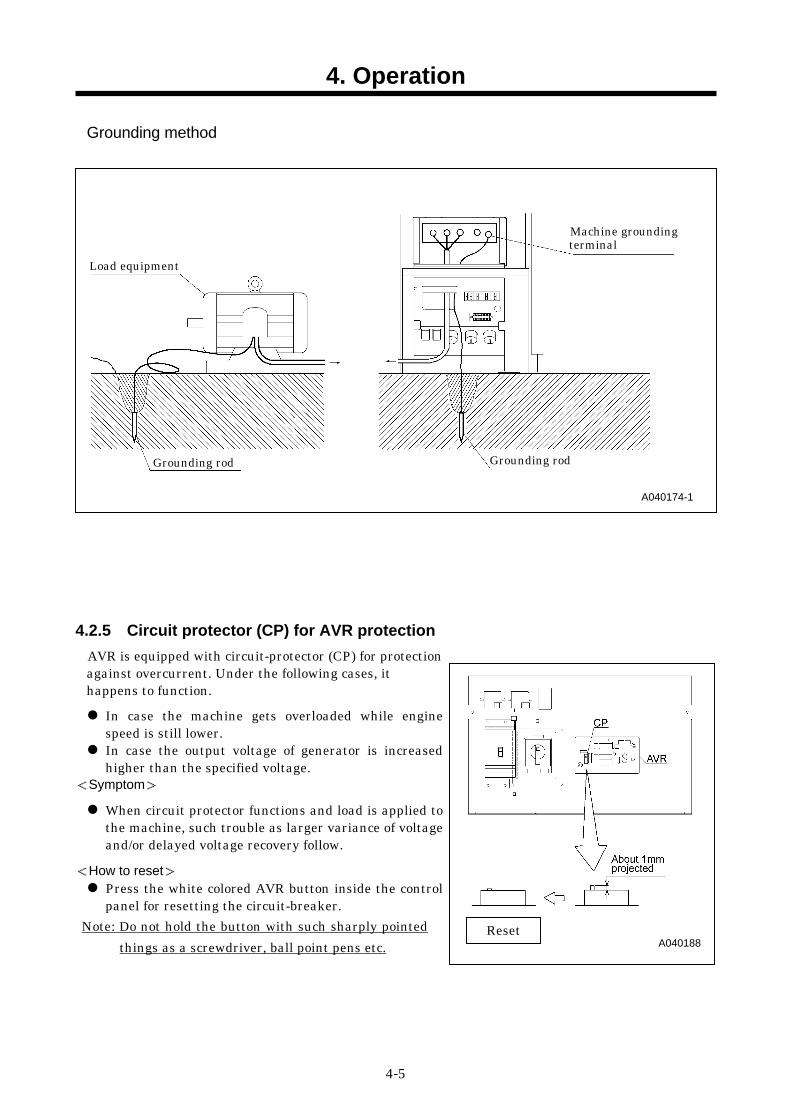
Grounding method
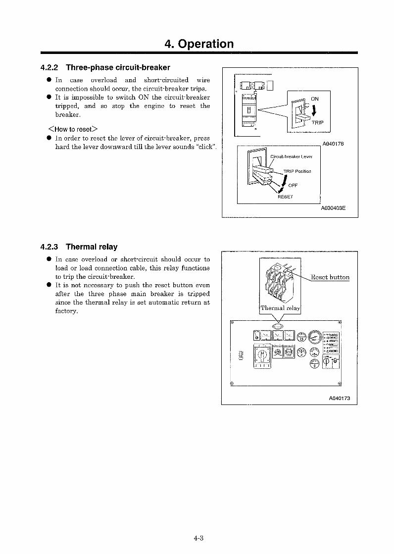
4.2.5 Circuit protector (CP) for AVR protection
AVR is equipped with circuit-protector (CP) for protection against overcurrent. Under the following cases, it happens to function.
In case the machine gets overloaded while engine speed is still lower. In case the output voltage of generator is increased higher than the specified voltage.
<Symptom> When circuit protector functions and load is applied to the machine, such trouble as larger variance of voltage and/or delayed voltage recovery follow.
<How to reset> Press the white colored AVR button inside the control panel for resetting the circuit-breaker.
Note: Do not hold the button with such sharply pointed things as a screwdriver, ball point pens etc.
A040188
Machine grounding terminal
Load equipment
Grounding rod Grounding rod
A040174-1
4. Operation
4-6
4.3 Check before Starting the Unit
Check before starting the unit Be sure to check the unit before operation. When any abnormality is found, be sure to repair it before starting the unit. Be sure to make daily check before operation. If the unit is operated without prior check and without noticing its abnormality, such operation could cause seizure of components or may even cause fire.
4.3.1 Check Engine Oil Level
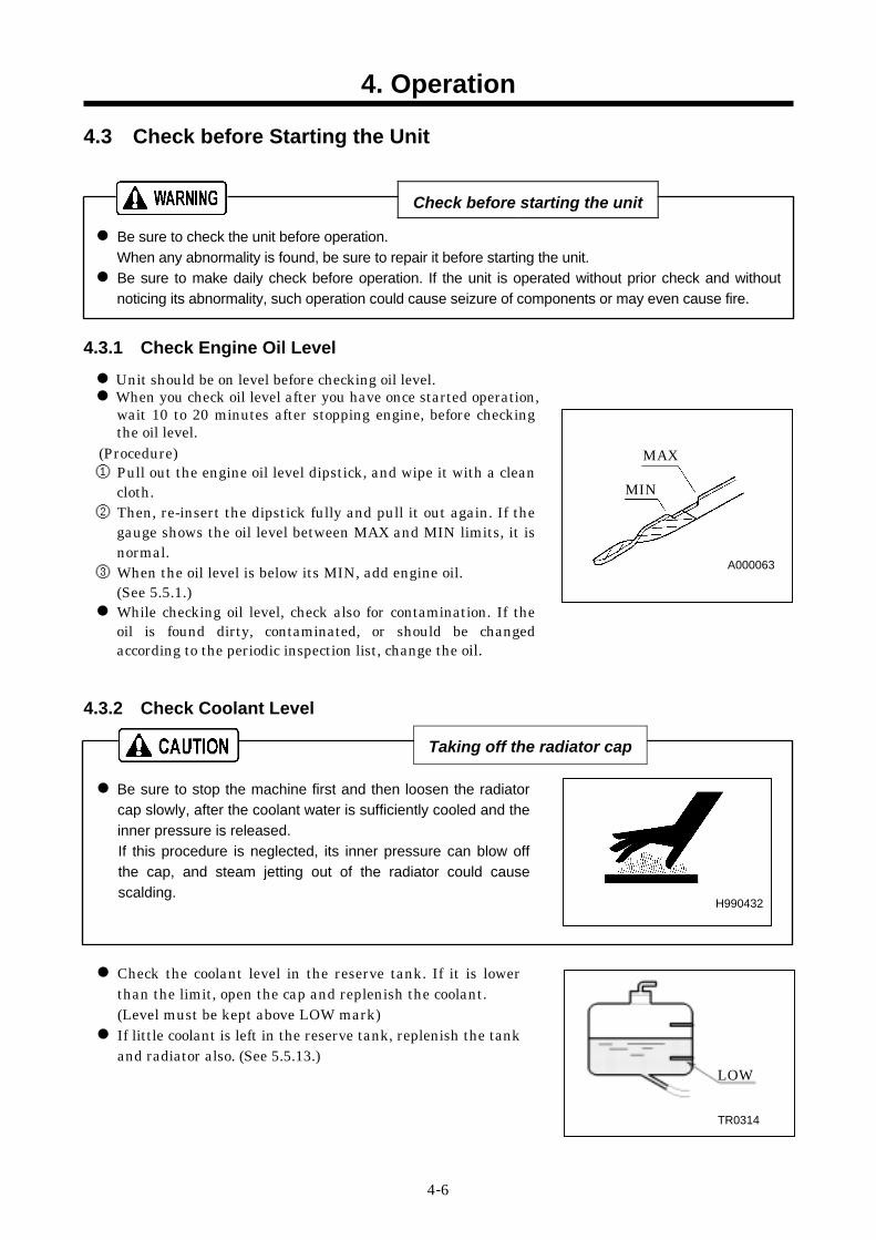
Unit should be on level before checking oil level. When you check oil level after you have once started operation, wait 10 to 20 minutes after stopping engine, before checking the oil level.
(Procedure) ① Pull out the engine oil level dipstick, and wipe it with a clean
cloth. ② Then, re-insert the dipstick fully and pull it out again. If the
gauge shows the oil level between MAX and MIN limits, it is normal.
③ When the oil level is below its MIN, add engine oil. (See 5.5.1.) While checking oil level, check also for contamination. If the oil is found dirty, contaminated, or should be changed according to the periodic inspection list, change the oil.
4.3.2 Check Coolant Level
Taking off the radiator cap
Be sure to stop the machine first and then loosen the radiator cap slowly, after the coolant water is sufficiently cooled and the inner pressure is released. If this procedure is neglected, its inner pressure can blow off the cap, and steam jetting out of the radiator could causescalding.
Check the coolant level in the reserve tank. If it is lower than the limit, open the cap and replenish the coolant. (Level must be kept above LOW mark) If little coolant is left in the reserve tank, replenish the tank and radiator also. (See 5.5.13.)
H990432
TR0314
LOW
A000063
MAX
MIN
4. Operation
4-7
4.3.3 Check Fuel Level
Be sure to use diesel fuel oil. (Using other oil will cause low power output or damage the engine.) Check fuel level gauge before operation. Replenish enough fuel to prevent fuel shortage during operation. Be sure to fasten the fuel tank cap firmly after replenishment. If fuel is spilt, wipe it up completely.
4.3.4 Check V-belt Tension
If V-belt tension too tight, it can cause shaft breakage or shorten the life of a bearing. If too loose, the belt may slip and will cause early breakage or damage to the belt.
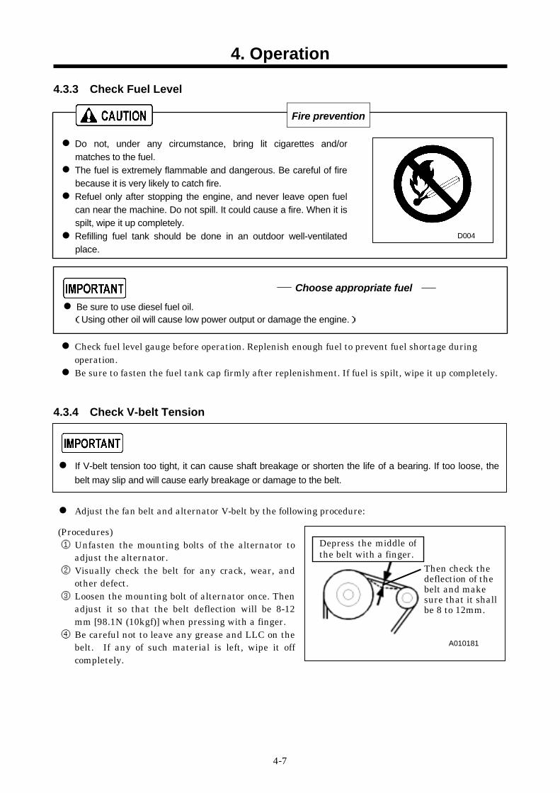
Adjust the fan belt and alternator V-belt by the following procedure:
(Procedures) ① Unfasten the mounting bolts of the alternator to
adjust the alternator. ② Visually check the belt for any crack, wear, and
other defect. ③ Loosen the mounting bolt of alternator once. Then
adjust it so that the belt deflection will be 8-12 mm [98.1N (10kgf)] when pressing with a finger.
④ Be careful not to leave any grease and LLC on the belt. If any of such material is left, wipe it off completely.
Fire prevention
Do not, under any circumstance, bring lit cigarettes and/or matches to the fuel. The fuel is extremely flammable and dangerous. Be careful of fire because it is very likely to catch fire. Refuel only after stopping the engine, and never leave open fuel can near the machine. Do not spill. It could cause a fire. When it is spilt, wipe it up completely. Refilling fuel tank should be done in an outdoor well-ventilated place.
D004
Choose appropriate fuel
A010181
Depress the middle ofthe belt with a finger.
Then check the deflection of the belt and make sure that it shall be 8 to 12mm.
4. Operation
4-8
4.4 Unit Operation
Keep the door shut and locked when machine is in operation. If opening the door is necessary, be careful not to touch rotating or hot parts. Burns or serious injury could result.
After the engine starts up, warm up it under unload for approx. five minutes. Warming up after starting up is necessary for smooth operation of the engine. Do not operate the engine at full load immediately after it starts up. This will shorten the equipment life. During the warm-up operation, examine the different parts of the equipment for any looseness, leakage of water, oil, fuel, and other irregularities. Also, make sure that the alarm lamps are off. Be sure to operate the generator at a rated frequency, irrespective of the load capacity. If the machine is operated with a frequency lower than the rated frequency, it could cause the generator or to be burned.
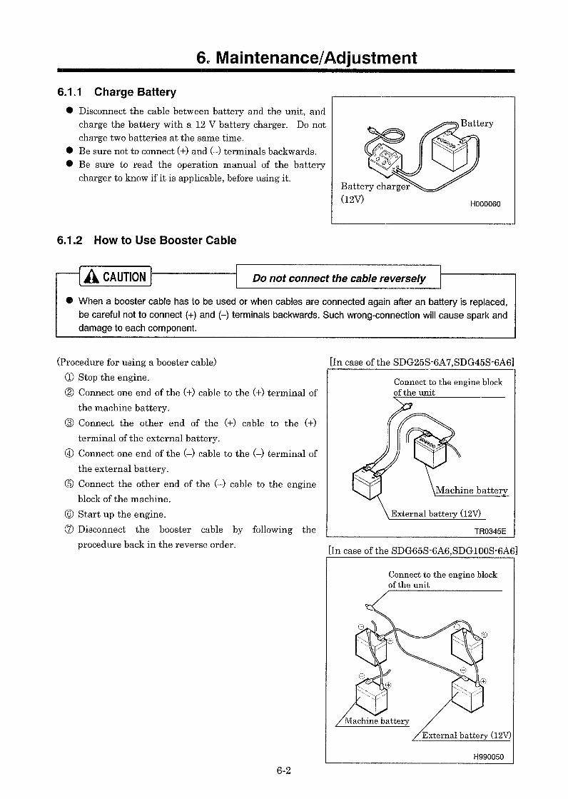
4.4.1 Procedure to Start the Unit
Follow the starting procedure below.
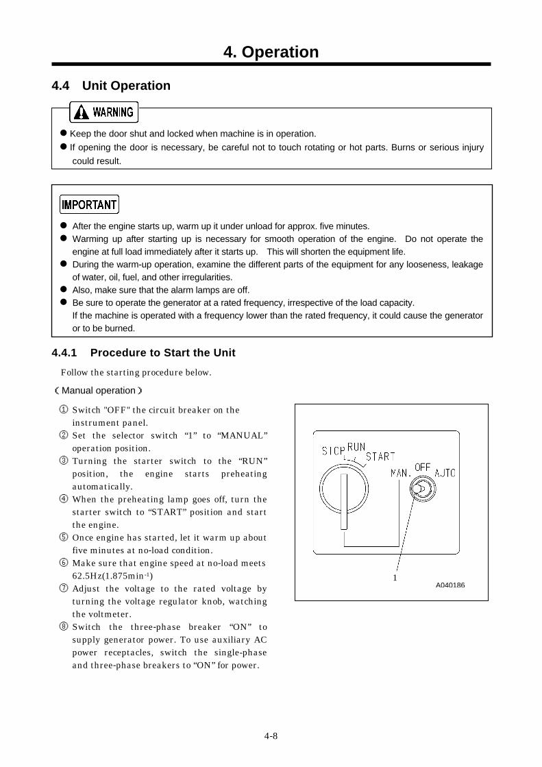
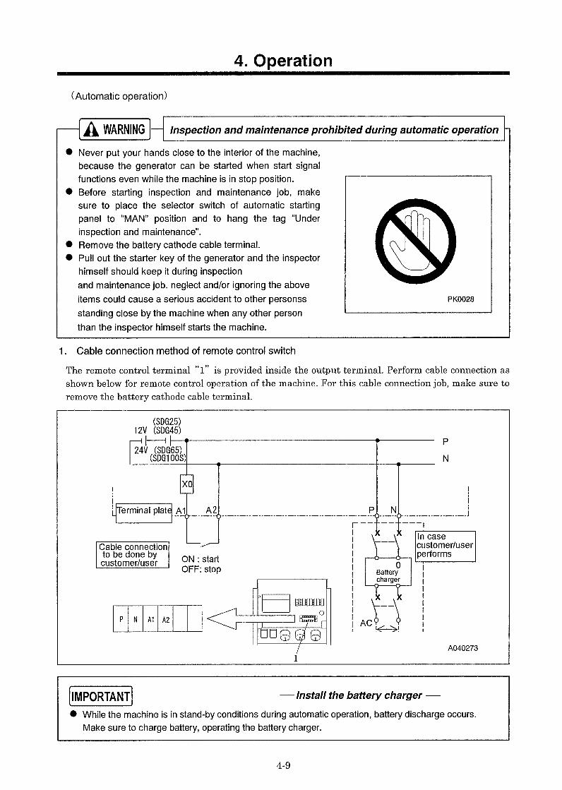
(Manual operation)
① Switch "OFF" the circuit breaker on the instrument panel.
② Set the selector switch “1” to “MANUAL” operation position.
③ Turning the starter switch to the “RUN” position, the engine starts preheating automatically.
④ When the preheating lamp goes off, turn the starter switch to “START” position and start the engine.
⑤ Once engine has started, let it warm up about five minutes at no-load condition.
⑥ Make sure that engine speed at no-load meets 62.5Hz(1.875min-1)
⑦ Adjust the voltage to the rated voltage by turning the voltage regulator knob, watching the voltmeter.
⑧ Switch the three-phase breaker “ON” to supply generator power. To use auxiliary AC power receptacles, switch the single-phase and three-phase breakers to “ON” for power.
A040186
1 A040186
4. Operation
4-11
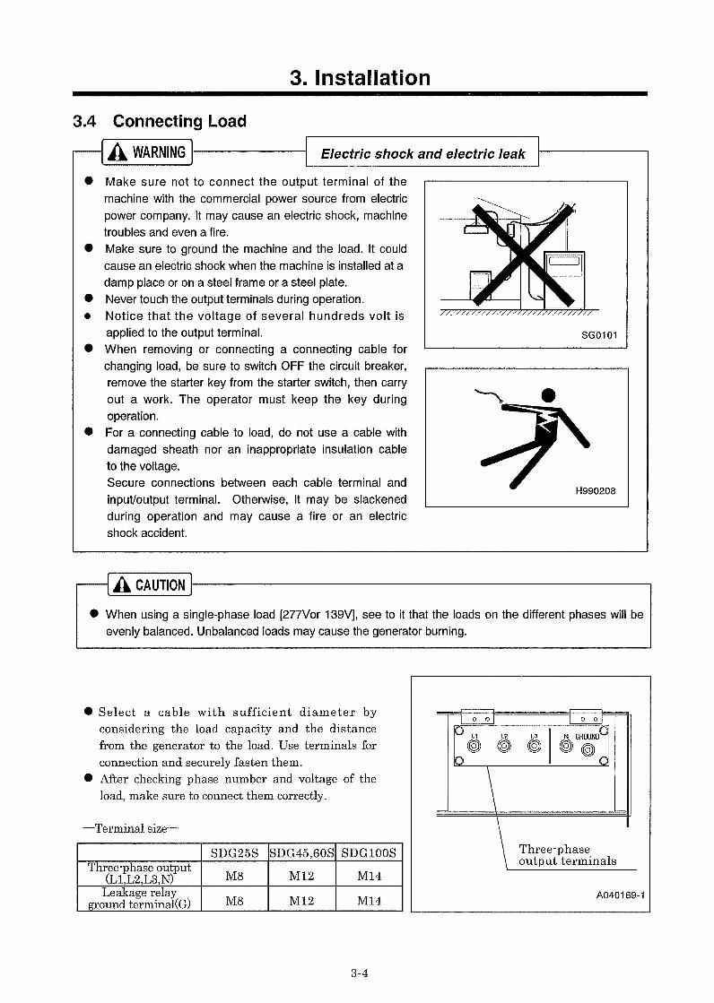
This machine is so designed for safety that operator may not touch the output terminal during operation. If you open the output terminal cover during operation with three-phase breaker switched “ON” , the three-phase breaker will be “OFF” to cut power supply to the output terminal. When starting operation , make sure that the output terminal cover is closed.
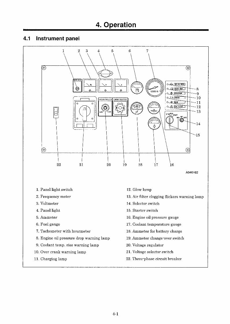
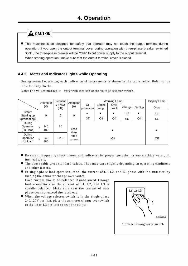
4.4.2 Meter and Indicator Lights while Operating
During normal operation, each indication of instruments is shown in the table below. Refer to the table for daily checks. Note; The values marked ※ vary with location of the voltage selector switch.
Warning Lamp Display Lamp
Voltmeter (V)
Frequency meter
(Hz)
Ammeter(A) Oil
puressureEngine temp.
Over crank Charge Air filter Glow
Before Starting up
(preheating)
0
0
0
●
Off
●
Off
●
Off
On
●
Off
On During
Operation (Full load)
240 480
60
During Operation (Unload)
240 480
62.5
Less than rated
current
●
Off
●
Off
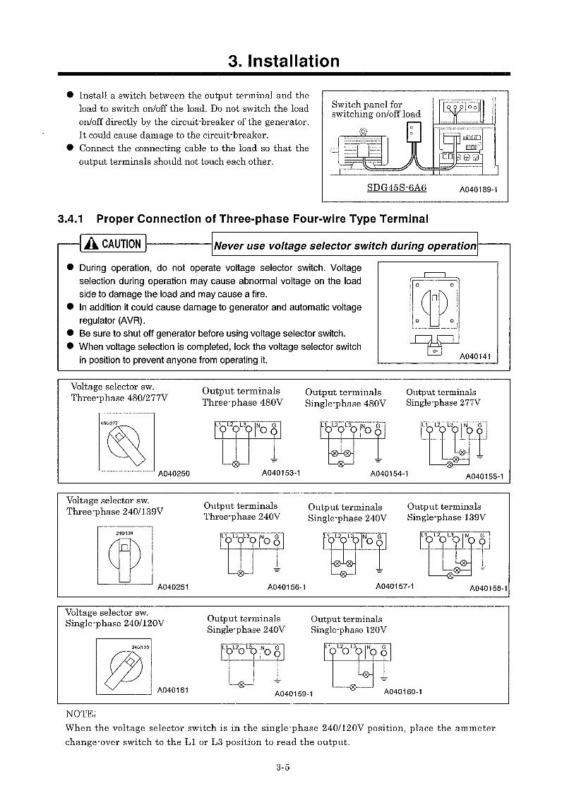
Be sure to frequently check meters and indicators for proper operation, or any machine water, oil, fuel leaks, etc. The above table gives standard values. They may vary slightly depending on operating conditions and other factors. In single-phase load operation, check the current of L1, L2, and L3 phase with the ammeter, by turning the ammeter change-over switch. Each current should be balanced if unbalanced. Change load connections so the current of L1, L2, and L3 is equally balanced. Make sure that the current of each phase does not exceed the rated one. When the voltage selector switch is in the single-phase 240/120V position, place the ammeter change-over switch to the L1 or L3 position to read the output.
※
※
A040164
Ammeter change-over switch
5. Periodic Inspection/Maintenance
5-1
5.1 Important Items at Periodic Inspection and Maintenance or after Maintenance
The manual shows proper interval for periodic inspection and maintenance under normally operating conditions. Inspection and maintenance should be performed more often under extremely harsh conditions.
Be sure to use recommended fuel, oil, grease, or antifreeze. Do not disassemble or adjust engine, compressor or part(s) for which inspection or maintenance is not referred to in this manual. Use genuine parts for replacement. Any breakdown, caused by using unapproved parts or by wrong handling, will be out of the scope of“WARRANTY”. Do not pour water or steam on electrical components.
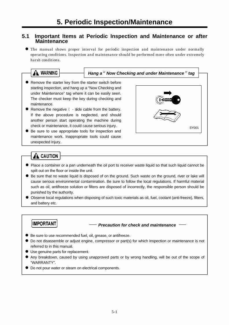
Hang a“Now Checking and under Maintenance”tag Remove the starter key from the starter switch before starting inspection, and hang up a “Now Checking and under Maintenance” tag where it can be easily seen. The checker must keep the key during checking and maintenance. Remove the negative (-) side cable from the battery. If the above procedure is neglected, and should another person start operating the machine during check or maintenance, it could cause serious injury. Be sure to use appropriate tools for inspection and maintenance work. Inappropriate tools could cause unexpected injury.
Place a container or a pan underneath the oil port to receiver waste liquid so that such liquid cannot be spilt out on the floor or inside the unit. Be sure that no waste liquid is disposed of on the ground. Such waste on the ground, river or lake will cause serious environmental contamination. Be sure to follow the local regulations. If harmful material such as oil, antifreeze solution or filters are disposed of incorrectly, the responsible person should be punished by the authority. Observe local regulations when disposing of such toxic materials as oil, fuel, coolant (anti-freeze), filters, and battery etc.
SY001
Precaution for check and maintenance
5. Periodic Inspection/Maintenance
5-2
5.2 Daily Inspection and Keeping Operation Log Be sure to carry out daily inspection every morning before operation. See Chapter 4 “OPERATION” of the manual for the details of inspection. Pay attention to and carefully observe the following points during daily operation or inspection and maintenance work. If any trouble or abnormality is found, immediately investigate its cause and make repairs. If the cause is unknown or not traceable, or if the trouble involves a part or component not described in the manual, ask your nearest dealer for information.
(a) Controls and instruments function properly. (b) Quantity and any leak of water, fuel, and oil or
any contamination should be checked. (c) Appearance, abnormal noise or excessive heat
should be checked. (d) Loose bolt or nut should be checked. (e) Any damage, wear or shortage of machine
components and parts should be checked. (f) Performance of each part or component should
be proper. Keep the operation log to record constant inspection of each component, so that trouble of the unit can be easily discovered and preventive measures can be taken. It is very useful to record information such as frequency, temperature, current, maintenance items and replenishment of lubricant on a daily maintenance log.
TR0049
5. Periodic Inspection/Maintenance
5-3
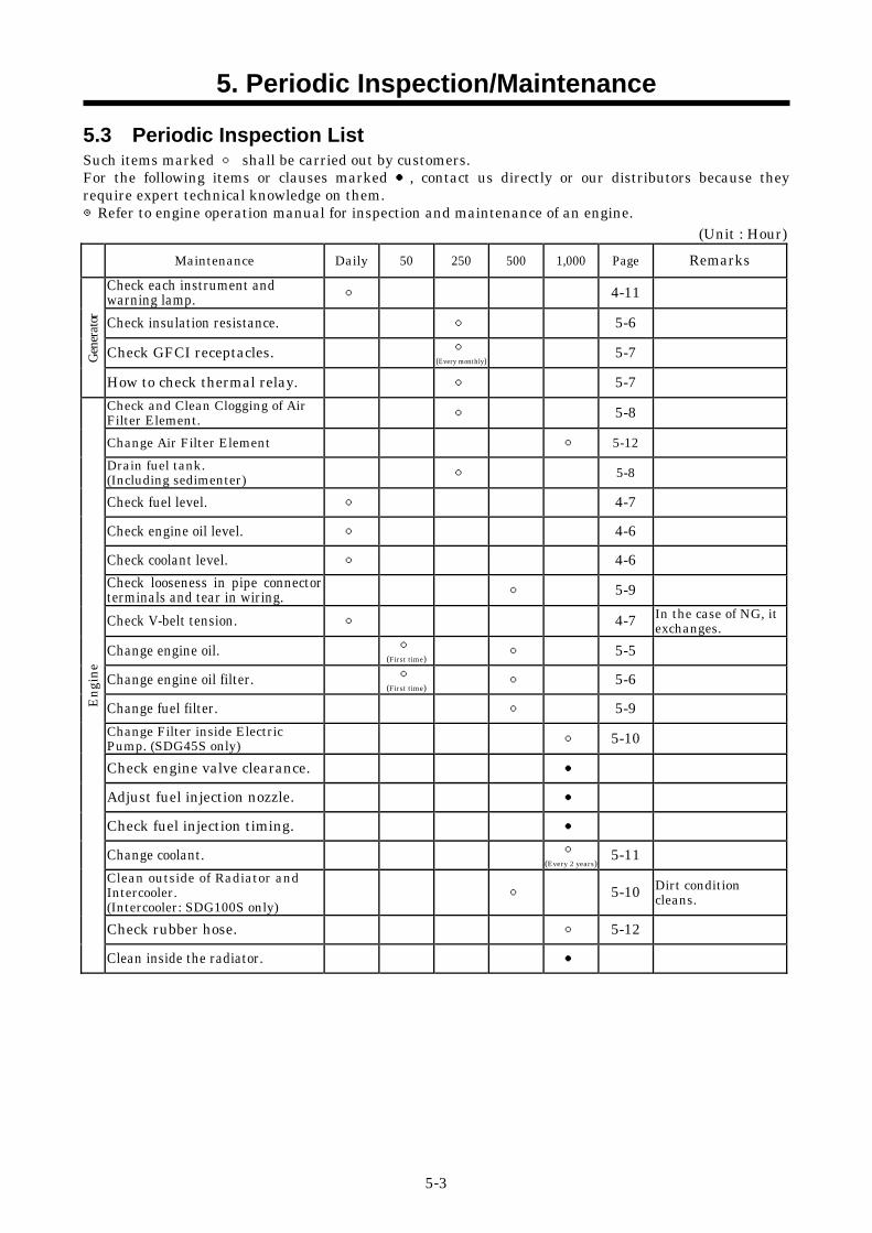
5.3 Periodic Inspection List Such items marked ○ shall be carried out by customers. For the following items or clauses marked ●, contact us directly or our distributors because they require expert technical knowledge on them. ◎Refer to engine operation manual for inspection and maintenance of an engine.
(Unit : Hour)
Maintenance Daily 50 250 500 1,000 Page Remarks
Check each instrument and warning lamp. ○ 4-11
Check insulation resistance. ○ 5-6
Check GFCI receptacles. ○ (Every monthly) 5-7 Ge
nera
tor
How to check thermal relay. ○ 5-7 Check and Clean Clogging of Air Filter Element. ○ 5-8
Change Air Filter Element ○ 5-12 Drain fuel tank. (Including sedimenter) ○ 5-8
Check fuel level. ○ 4-7
Check engine oil level. ○ 4-6
Check coolant level. ○ 4-6 Check looseness in pipe connector terminals and tear in wiring. ○ 5-9
Check V-belt tension. ○ 4-7 In the case of NG, it exchanges.
Change engine oil. ○ (First time) ○ 5-5
Change engine oil filter. ○ (First time) ○ 5-6
Change fuel filter. ○ 5-9 Change Filter inside Electric Pump. (SDG45S only) ○ 5-10
Check engine valve clearance. ●
Adjust fuel injection nozzle. ●
Check fuel injection timing. ●
Change coolant. ○ (Every 2 years) 5-11
Clean outside of Radiator and Intercooler. (Intercooler: SDG100S only)
○ 5-10 Dirt condition cleans.
Check rubber hose. ○ 5-12
Engi
ne
Clean inside the radiator. ●
5. Periodic Inspection/Maintenance
5-4
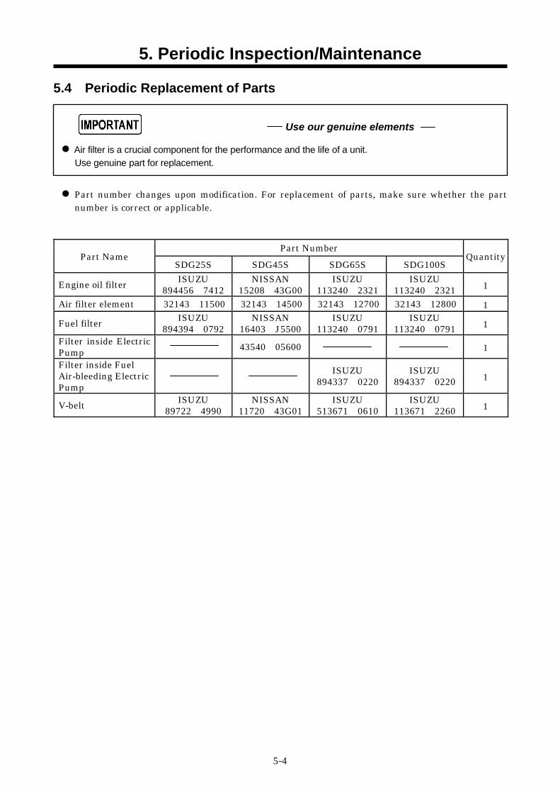
5.4 Periodic Replacement of Parts
Air filter is a crucial component for the performance and the life of a unit. Use genuine part for replacement.
Part number changes upon modification. For replacement of parts, make sure whether the part number is correct or applicable.
Part Number Part Name
SDG25S SDG45S SDG65S SDG100S Quantity
Engine oil filter ISUZU 894456 7412
NISSAN 15208 43G00
ISUZU 113240 2321
ISUZU 113240 2321 1
Air filter element 32143 11500 32143 14500 32143 12700 32143 12800 1
Fuel filter ISUZU 894394 0792
NISSAN 16403 J5500
ISUZU 113240 0791
ISUZU 113240 0791 1
Filter inside Electric Pump
43540 05600 1 Filter inside Fuel Air-bleeding Electric Pump
ISUZU 894337 0220
ISUZU 894337 0220 1
V-belt ISUZU 89722 4990
NISSAN 11720 43G01
ISUZU 513671 0610
ISUZU 113671 2260 1
Use our genuine elements
5. Periodic Inspection/Maintenance
5-5
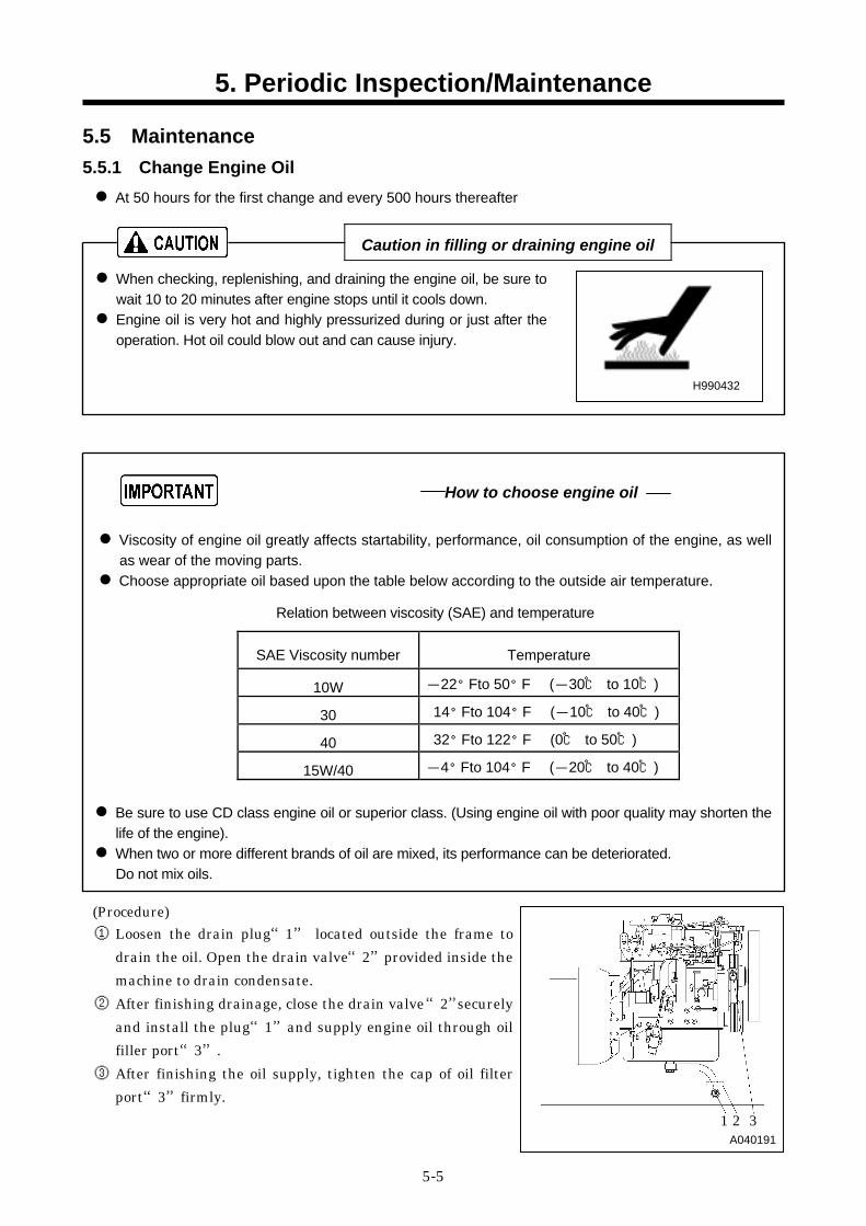
5.5 Maintenance 5.5.1 Change Engine Oil At 50 hours for the first change and every 500 hours thereafter
Caution in filling or draining engine oil When checking, replenishing, and draining the engine oil, be sure to wait 10 to 20 minutes after engine stops until it cools down. Engine oil is very hot and highly pressurized during or just after the operation. Hot oil could blow out and can cause injury.
Viscosity of engine oil greatly affects startability, performance, oil consumption of the engine, as well as wear of the moving parts. Choose appropriate oil based upon the table below according to the outside air temperature.
Relation between viscosity (SAE) and temperature
SAE Viscosity number Temperature
10W -22°F to 50°F (-30℃ to 10℃)
30 14°F to 104°F (-10℃ to 40℃)
40 32°F to 122°F (0℃ to 50℃)
15W/40 -4°F to 104°F (-20℃ to 40℃)
Be sure to use CD class engine oil or superior class. (Using engine oil with poor quality may shorten the life of the engine). When two or more different brands of oil are mixed, its performance can be deteriorated. Do not mix oils.
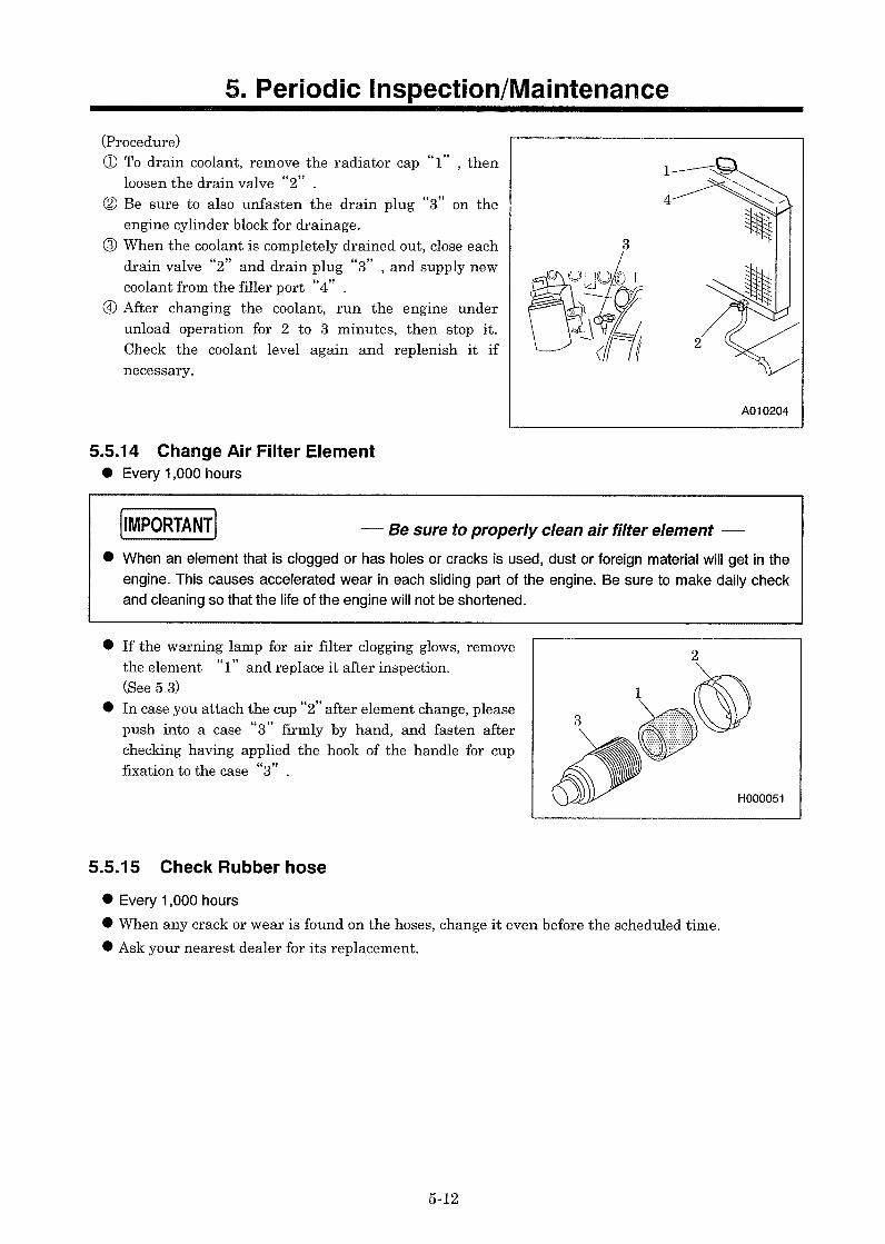
(Procedure) ① Loosen the drain plug“1” located outside the frame to
drain the oil. Open the drain valve“2”provided inside the machine to drain condensate.
② After finishing drainage, close the drain valve “2”securely and install the plug“1”and supply engine oil through oil filler port“3”.
③ After finishing the oil supply, tighten the cap of oil filter port“3”firmly.
How to choose engine oil
H990432
1 2 3 A040191
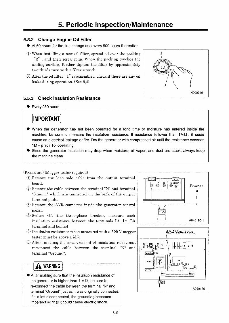
5. Periodic Inspection/Maintenance
5-10
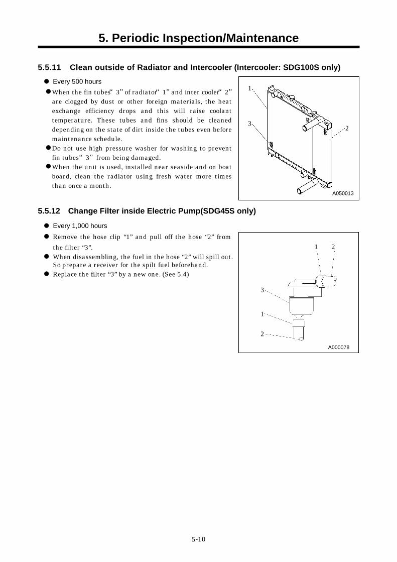
5.5.11 Clean outside of Radiator and Intercooler (Intercooler: SDG100S only)
Every 500 hours When the fin tubes“3”of radiator“1”and inter cooler“2” are clogged by dust or other foreign materials, the heat exchange efficiency drops and this will raise coolant temperature. These tubes and fins should be cleaned depending on the state of dirt inside the tubes even before maintenance schedule. Do not use high pressure washer for washing to prevent fin tubes“3”from being damaged. When the unit is used, installed near seaside and on boat board, clean the radiator using fresh water more times than once a month.
5.5.12 Change Filter inside Electric Pump(SDG45S only)
Every 1,000 hours Remove the hose clip “1” and pull off the hose “2” from the filter “3”. When disassembling, the fuel in the hose “2” will spill out. So prepare a receiver for the spilt fuel beforehand. Replace the filter “3” by a new one. (See 5.4)
A000078
A050013
1 2
3 1 2
1
3 2
5. Periodic Inspection/Maintenance
5-11
5.5.13 Change Coolant 1,000 hours or every 2 years
Taking off radiator cap Be sure to stop the machine and loosen the radiator cap slowly, after the coolant water is sufficiently cooled and the inner pressure is released, then take the cap off. If this procedure is neglected, the inner pressure can blow off the cap. Steam jetting out of the radiator could result in causing scalding. Follow the procedure under all circumstances.
How to handle LLC(Antifreeze) LLC (Antifreeze) is a toxic material. When a person has drunk LLC (Antifreeze) by accident, make him vomit and make him see a doctor
immediately. When a person gets LLC (Antifreeze) in his eyes, wash the eyes with clean running water and make
him see a doctor immediately. When LLC (Antifreeze) is stored, put it in a container with an indication saying "LLC (Antifreeze)
inside" and seal it up, then Keep it in a place away from children. Beware of flames. Follow the designated regulations to dispose of LLC (Antifreeze).
Use soft water of good quality such as tap water for coolant. When water with dirt, sand, and/or dust contained, or hard water such as well water (ground water) is used, this will cause deposits inside radiator or on cylinder head, and will cause engine overheat due to poor flow of coolant. When the unit is used in a cold region and possible freezing is expected, it is recommended to use LLC (Antifreeze) for the coolant. Adjust mixing ratio of LLC with water according to the temperature. Use LLC within the range of its mixing ratio between 35 and 60%. If LLC in the water exceeds more than 60%, it may decrease its antifreezing effect.
Reference of LLC mixing ratio Temperature Mixing ratio
-4°F (-20℃) 35% -40°F (-40℃) 55%
H990432
Quality of coolant and antifreeze
6. Maintenance/Adjustment
6-1
6.1 Maintenance of Battery
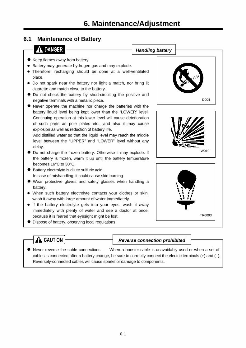
Handling battery Keep flames away from battery. Battery may generate hydrogen gas and may explode. Therefore, recharging should be done at a well-ventilated
place. Do not spark near the battery nor light a match, nor bring lit
cigarette and match close to the battery. Do not check the battery by short-circuiting the positive and negative terminals with a metallic piece. Never operate the machine nor charge the batteries with the battery liquid level being kept lower than the “LOWER” level. Continuing operation at this lower level will cause deterioration of such parts as pole plates etc., and also it may cause explosion as well as reduction of battery life. Add distilled water so that the liquid level may reach the middle level between the “UPPER” and “LOWER” level without any delay. Do not charge the frozen battery. Otherwise it may explode. If the battery is frozen, warm it up until the battery temperature becomes 16°C to 30°C. Battery electrolyte is dilute sulfuric acid. In case of mishandling, it could cause skin burning. Wear protective gloves and safety glasses when handling a battery. When such battery electrolyte contacts your clothes or skin,
wash it away with large amount of water immediately. If the battery electrolyte gets into your eyes, wash it away
immediately with plenty of water and see a doctor at once, because it is feared that eyesight might be lost. Dispose of battery, observing local regulations.
D004
W010
TR0093
Reverse connection prohibited Never reverse the cable connections. - When a booster-cable is unavoidably used or when a set of cables is connected after a battery change, be sure to correctly connect the electric terminals (+) and (–). Reversely-connected cables will cause sparks or damage to components.
6. Maintenance/Adjustment
6-3
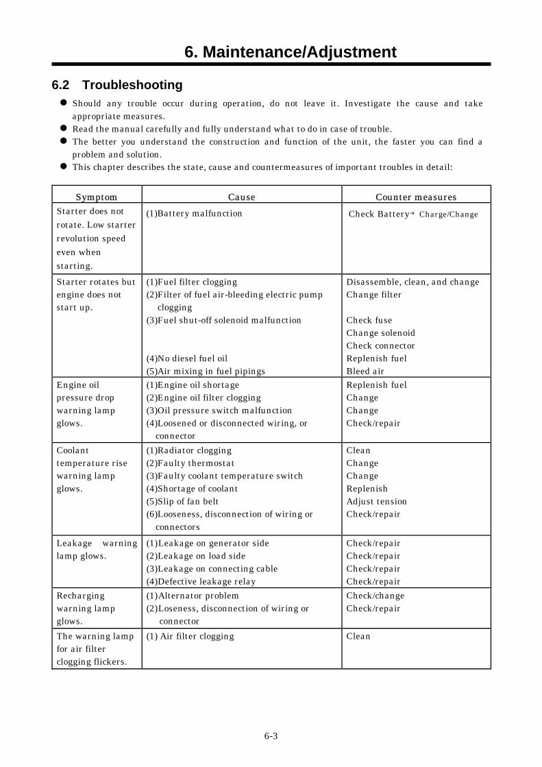
6.2 Troubleshooting Should any trouble occur during operation, do not leave it. Investigate the cause and take appropriate measures. Read the manual carefully and fully understand what to do in case of trouble. The better you understand the construction and function of the unit, the faster you can find a problem and solution. This chapter describes the state, cause and countermeasures of important troubles in detail:
Symptom Cause Counter measures
Starter does not rotate. Low starter revolution speed even when starting.
(1)Battery malfunction
Check Battery →Charge/Change
Starter rotates but engine does not start up.
(1)Fuel filter clogging (2)Filter of fuel air-bleeding electric pump
clogging (3)Fuel shut-off solenoid malfunction (4)No diesel fuel oil (5)Air mixing in fuel pipings
Disassemble, clean, and change Change filter Check fuse Change solenoid Check connector Replenish fuel Bleed air
Engine oil pressure drop warning lamp glows.
(1)Engine oil shortage (2)Engine oil filter clogging (3)Oil pressure switch malfunction (4)Loosened or disconnected wiring, or
connector
Replenish fuel Change Change Check/repair
Coolant temperature rise warning lamp glows.
(1)Radiator clogging (2)Faulty thermostat (3)Faulty coolant temperature switch (4)Shortage of coolant (5)Slip of fan belt (6)Looseness, disconnection of wiring or
connectors
Clean Change Change Replenish Adjust tension Check/repair
Leakage warning lamp glows.
(1) Leakage on generator side (2) Leakage on load side (3) Leakage on connecting cable (4) Defective leakage relay
Check/repair Check/repair Check/repair Check/repair
Recharging warning lamp glows.
(1) Alternator problem (2) Loseness, disconnection of wiring or
connector
Check/change Check/repair
The warning lamp for air filter clogging flickers.
(1) Air filter clogging Clean
6. Maintenance/Adjustment
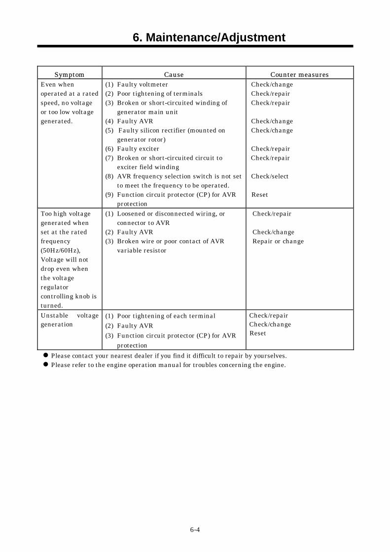
6-4
Symptom Cause Counter measures Even when operated at a rated speed, no voltage or too low voltage generated.
(1) Faulty voltmeter (2) Poor tightening of terminals (3) Broken or short-circuited winding of
generator main unit (4) Faulty AVR (5) Faulty silicon rectifier (mounted on
generator rotor) (6) Faulty exciter (7) Broken or short-circuited circuit to
exciter field winding (8) AVR frequency selection switch is not set
to meet the frequency to be operated. (9) Function circuit protector (CP) for AVR
protection
Check/change Check/repair Check/repair Check/change Check/change Check/repair
Check/repair Check/select
Reset
Too high voltage generated when set at the rated frequency (50Hz/60Hz), Voltage will not drop even when the voltage regulator controlling knob is turned.
(1) Loosened or disconnected wiring, or connector to AVR
(2) Faulty AVR (3) Broken wire or poor contact of AVR
variable resistor
Check/repair Check/change Repair or change
Unstable voltage generation
(1) Poor tightening of each terminal (2) Faulty AVR (3) Function circuit protector (CP) for AVR
protection
Check/repair Check/change Reset
Please contact your nearest dealer if you find it difficult to repair by yourselves. Please refer to the engine operation manual for troubles concerning the engine.
7. Storage of the Unit
7-1
7.1 Preparation for Long-term Storage
When the unit is to be kept unused in storage for a long time, be sure to follow the preparations below and put the unit in a dry and less dusty place. Put the unit in a temporary cabin if it is stored outside. Avoid leaving the unit outside with a sheet cover directly on the paint for a long time, or this will cause rust to the unit. Perform the following treatments at least once every three months.
(Procedure) ① Discharge existing lubricant from the engine oil pan. Pour new lubricant in the engine to clean
its inside. After running it for a while, drain it again. ② Spread lubricant on each moving part. ③ Completely charge the battery and disconnect grounding wires. Remove the battery from the
unit, if possible, and store it in a dry place. (Charge the battery at least once every month.) ④ Discharge coolant and fuel from the unit. ⑤ Seal air-intake port of engine and other openings like the muffler with a vinyl sheet, packing
tape, etc., to prevent moisture and dust from getting in the unit. ⑥ Be sure to repair any trouble and maintain the unit so that it will be ready for the next
operation.
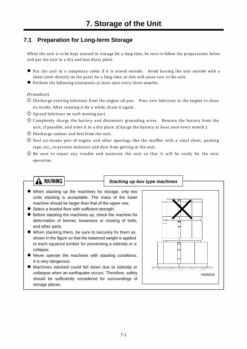
Stacking up box type machines When stacking up the machines for storage, only two units stacking is acceptable. The mass of the lower machine should be larger than that of the upper one. Select a leveled floor with sufficient strength. Before stacking the machines up, check the machine for deformation of bonnet, looseness or missing of bolts, and other parts. When stacking them, be sure to securely fix them as shown in the figure so that the balanced weight is applied to each squared lumber for preventing a sideslip or a collapse. Never operate the machines with stacking conditions. It is very dangerous. Machines stacked could fall down due to sideslip or collaspse when an earthquake occurs. Therefore, safety should be sufficiently considered for surroundings of storage places.
H000028
8. Specifications
8-1
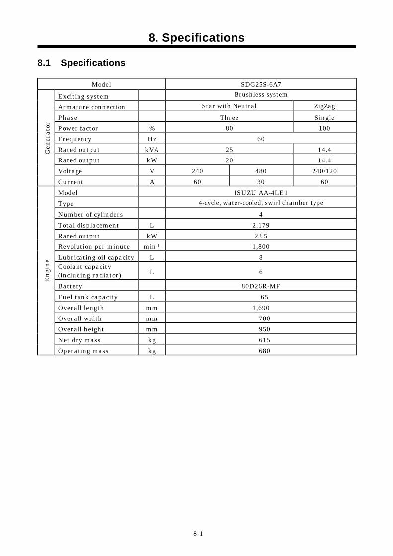
8.1 Specifications
Model SDG25S-6A7 Exciting system Brushless system
Armature connection Star with Neutral ZigZag Phase Three Single Power factor % 80 100 Frequency Hz 60 Rated output kVA 25 14.4 Rated output kW 20 14.4 Voltage V 240 480 240/120
Gen
erat
or
Current A 60 30 60 Model ISUZU AA-4LE1 Type 4-cycle, water-cooled, swirl chamber type Number of cylinders 4 Total displacement L 2.179 Rated output kW 23.5 Revolution per minute min-1 1,800 Lubricating oil capacity L 8 Coolant capacity (including radiator) L 6
Battery 80D26R-MF Fuel tank capacity L 65 Overall length mm 1,690 Overall width mm 700 Overall height mm 950 Net dry mass kg 615
Engi
ne
Operating mass kg 680
8. Specifications
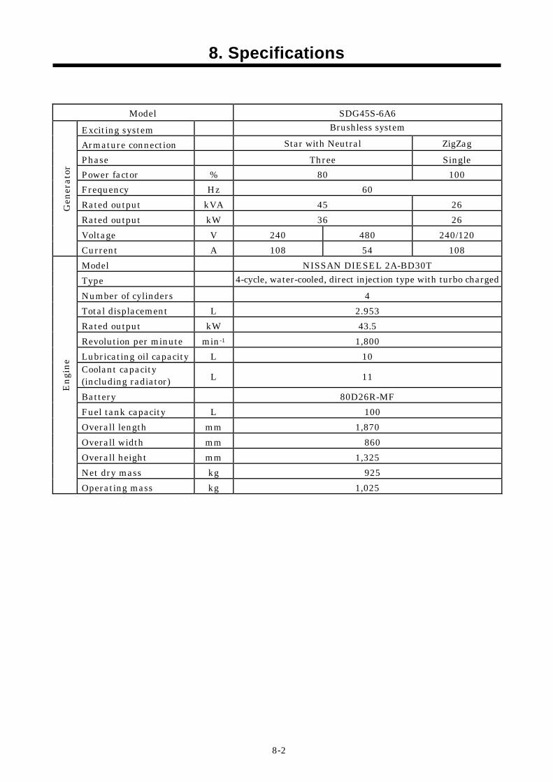
8-2
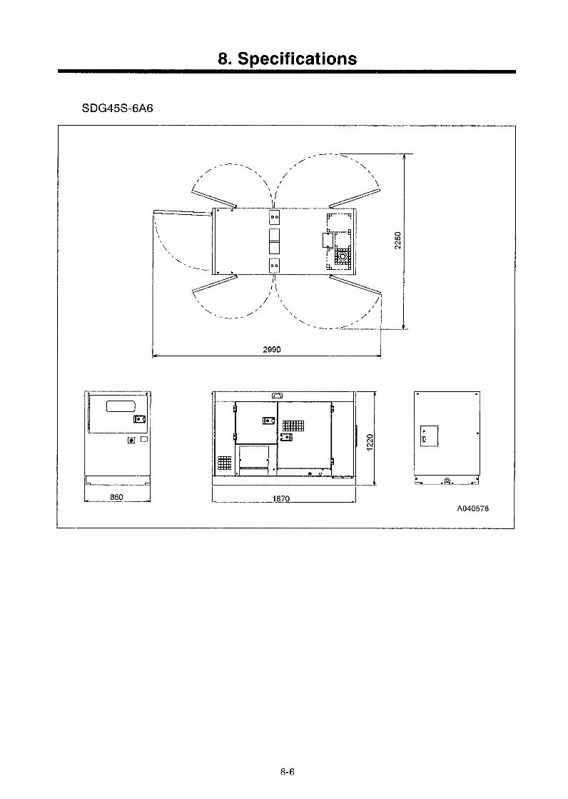
Model SDG45S-6A6 Exciting system Brushless system
Armature connection Star with Neutral ZigZag Phase Three Single Power factor % 80 100 Frequency Hz 60 Rated output kVA 45 26 Rated output kW 36 26 Voltage V 240 480 240/120
Gen
erat
or
Current A 108 54 108 Model NISSAN DIESEL 2A-BD30T Type 4-cycle, water-cooled, direct injection type with turbo charged Number of cylinders 4 Total displacement L 2.953 Rated output kW 43.5 Revolution per minute min-1 1,800 Lubricating oil capacity L 10 Coolant capacity (including radiator) L 11
Battery 80D26R-MF Fuel tank capacity L 100 Overall length mm 1,870 Overall width mm 860 Overall height mm 1,325 Net dry mass kg 925
Engi
ne
Operating mass kg 1,025
8. Specifications
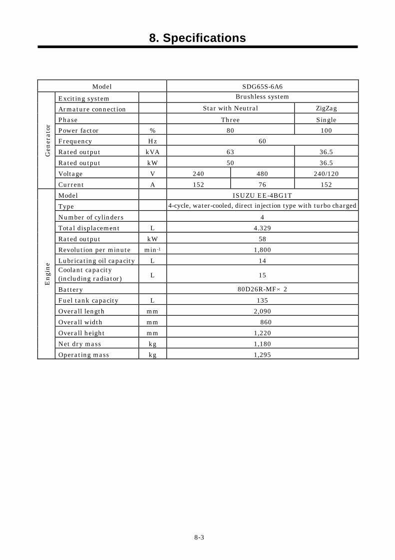
8-3
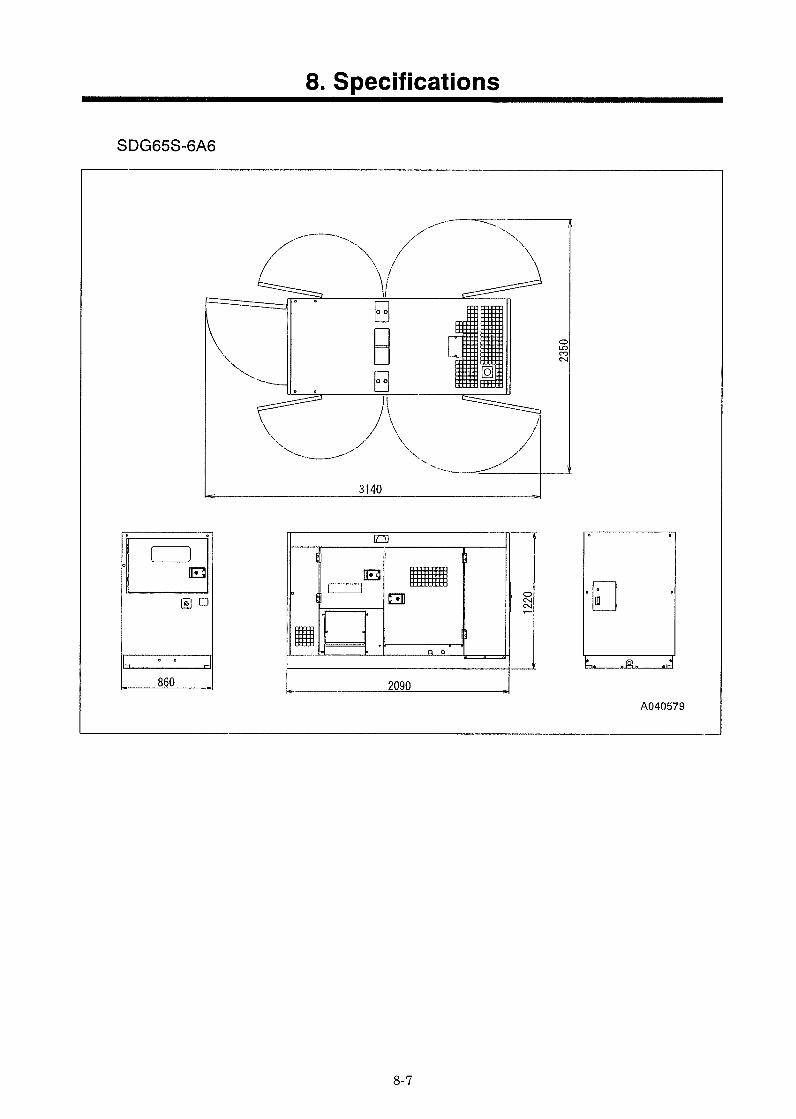
Model SDG65S-6A6 Exciting system Brushless system
Armature connection Star with Neutral ZigZag Phase Three Single Power factor % 80 100 Frequency Hz 60 Rated output kVA 63 36.5 Rated output kW 50 36.5 Voltage V 240 480 240/120
Gen
erat
or
Current A 152 76 152 Model ISUZU EE-4BG1T Type 4-cycle, water-cooled, direct injection type with turbo charged Number of cylinders 4 Total displacement L 4.329 Rated output kW 58 Revolution per minute min-1 1,800 Lubricating oil capacity L 14 Coolant capacity (including radiator) L 15
Battery 80D26R-MF×2 Fuel tank capacity L 135 Overall length mm 2,090 Overall width mm 860 Overall height mm 1,220 Net dry mass kg 1,180
Engi
ne
Operating mass kg 1,295
8. Specifications
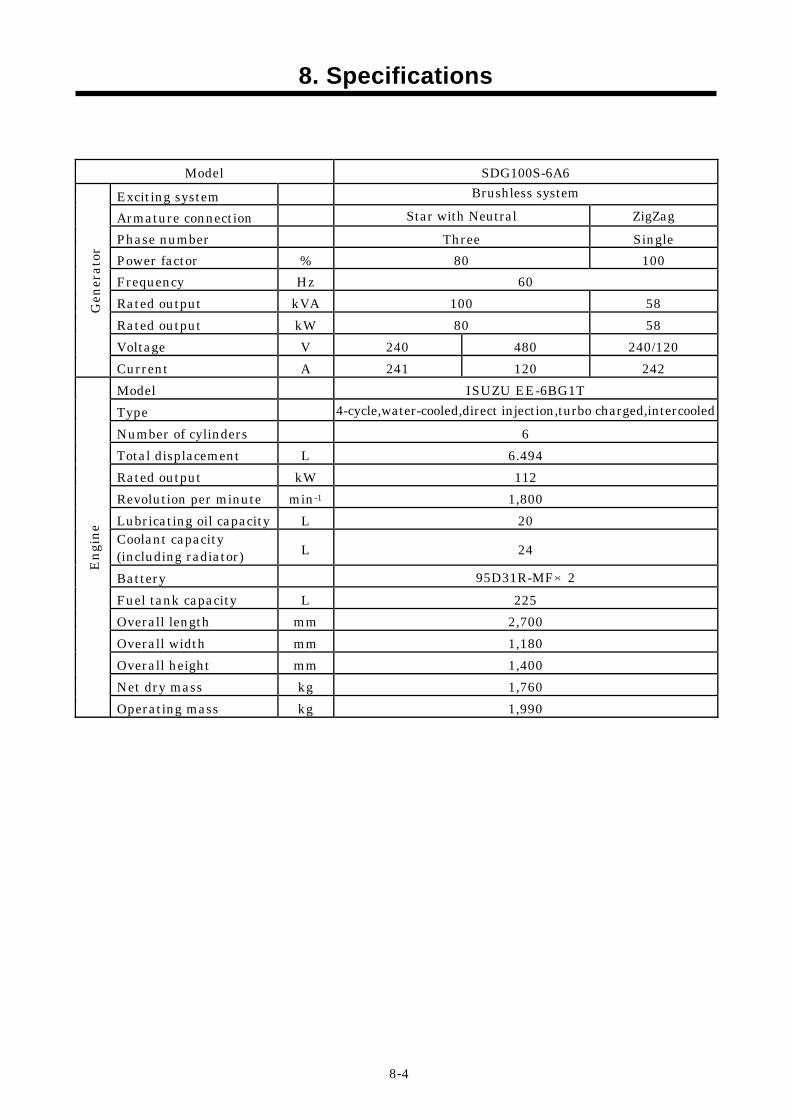
8-4
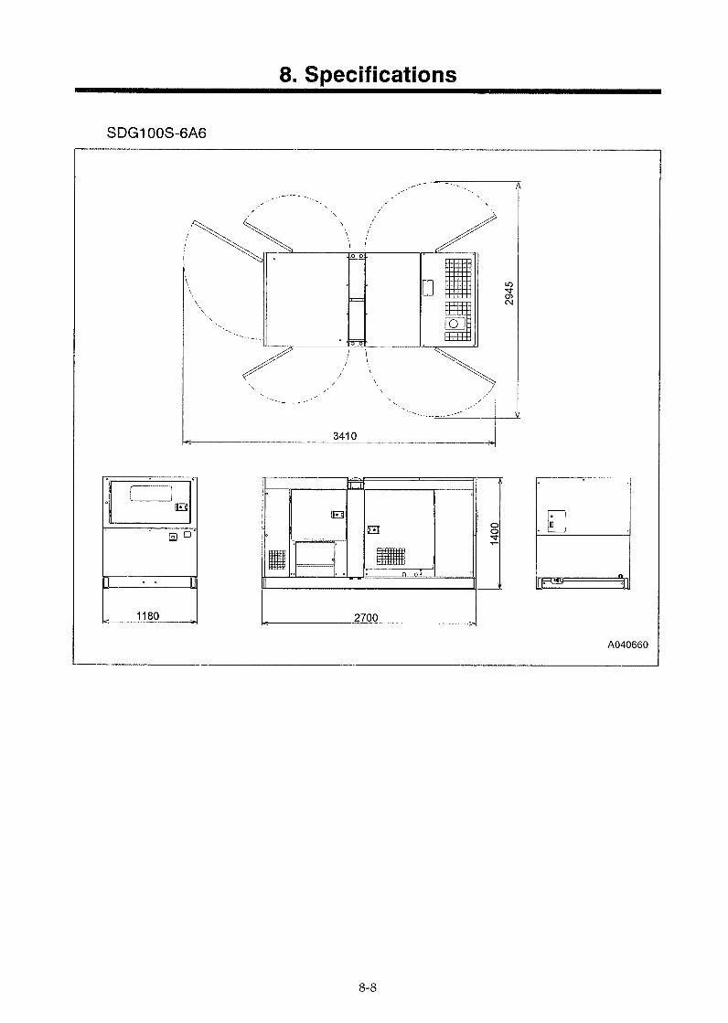
Model SDG100S-6A6 Exciting system Brushless system
Armature connection Star with Neutral ZigZag Phase number Three Single Power factor % 80 100 Frequency Hz 60 Rated output kVA 100 58 Rated output kW 80 58 Voltage V 240 480 240/120
Gen
erat
or
Current A 241 120 242 Model ISUZU EE-6BG1T Type 4-cycle,water-cooled,direct injection,turbo charged,intercooled Number of cylinders 6 Total displacement L 6.494 Rated output kW 112 Revolution per minute min-1 1,800 Lubricating oil capacity L 20 Coolant capacity (including radiator) L 24
Battery 95D31R-MF×2 Fuel tank capacity L 225 Overall length mm 2,700 Overall width mm 1,180 Overall height mm 1,400 Net dry mass kg 1,760
Engi
ne
Operating mass kg 1,990
8. Specifications
8-5
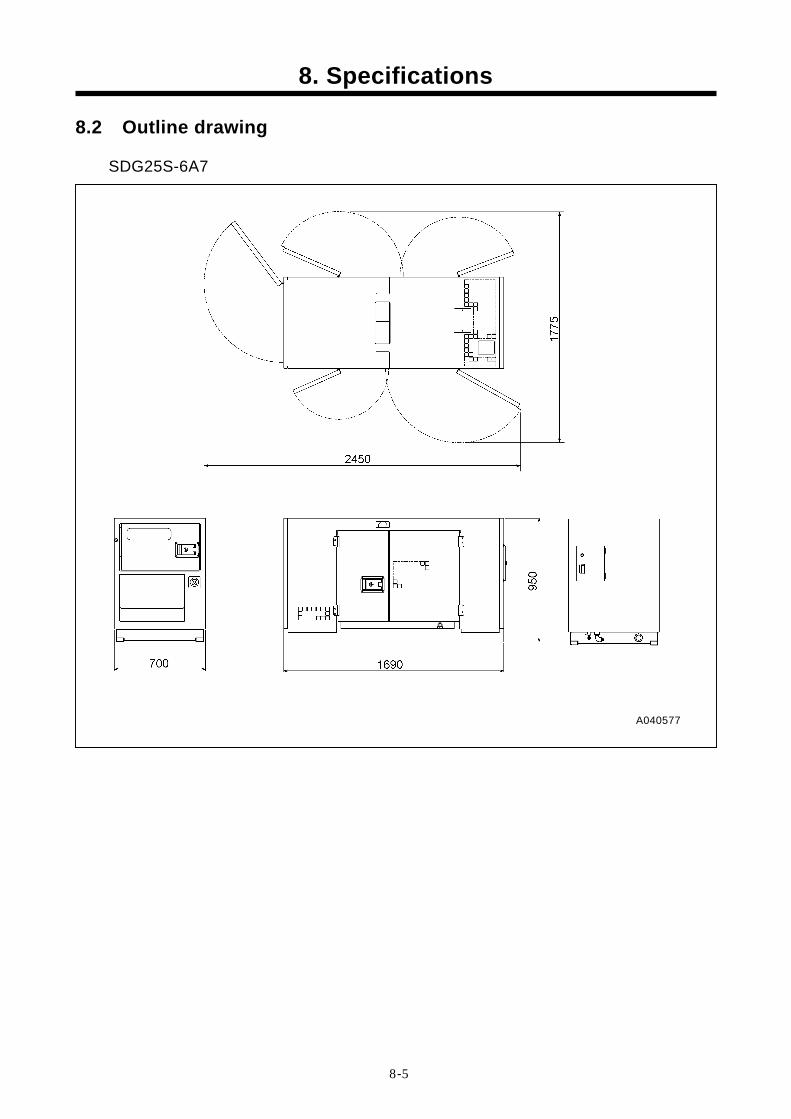
8.2 Outline drawing
SDG25S-6A7
A040577
9. Wiring Diagram
9-1
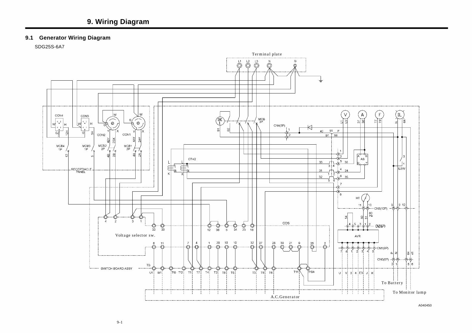
9.1 Generator Wiring Diagram SDG25S-6A7
To Monitor lamp A.C.Generator
A040450
To Battery
Voltage selector sw.
Terminal plate
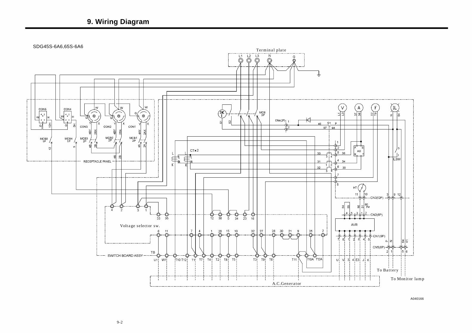
9. Wiring Diagram
9-2
SDG45S-6A6,65S-6A6
To Monitor lamp
Terminal plate
A.C.Generator
A040166
To Battery
Voltage selector sw.
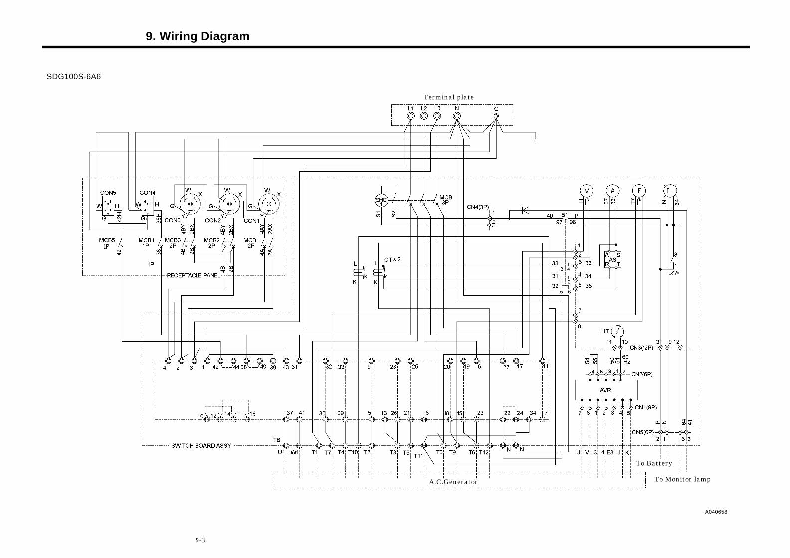
9. Wiring Diagram
9-3
SDG100S-6A6
A040658
Terminal plate
A.C.Generator
To Battery
To Monitor lamp
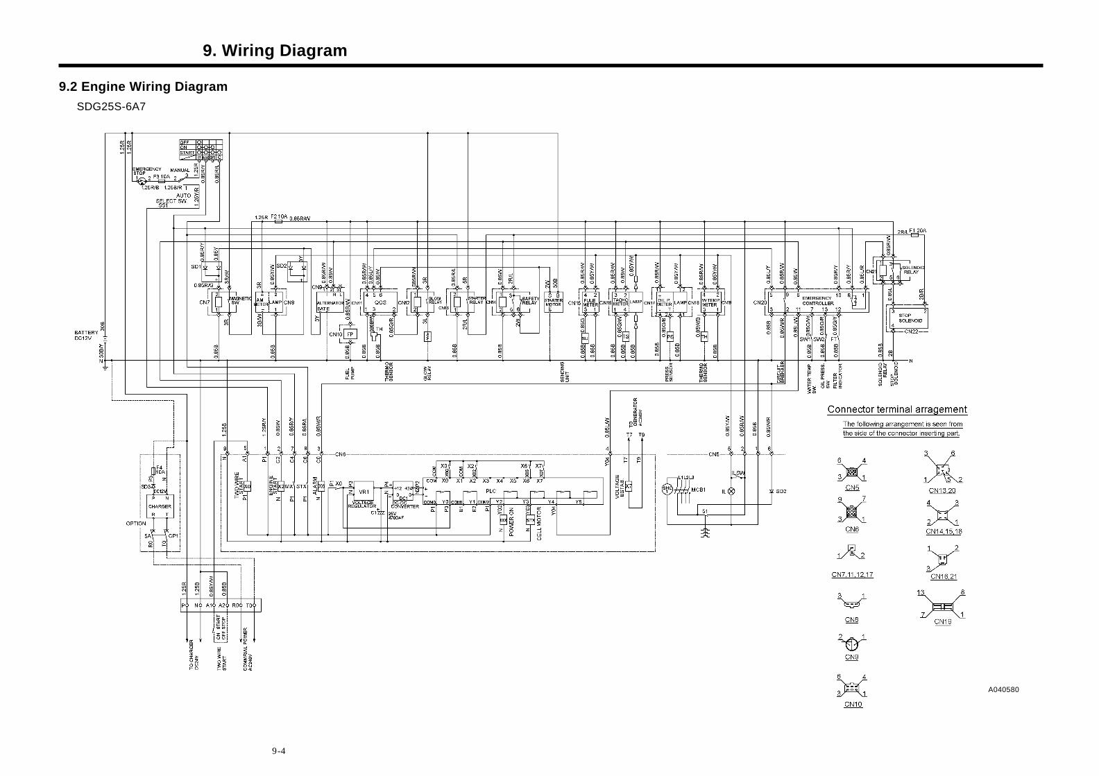
9. Wiring Diagram
9-4
9.2 Engine Wiring Diagram SDG25S-6A7
A040580
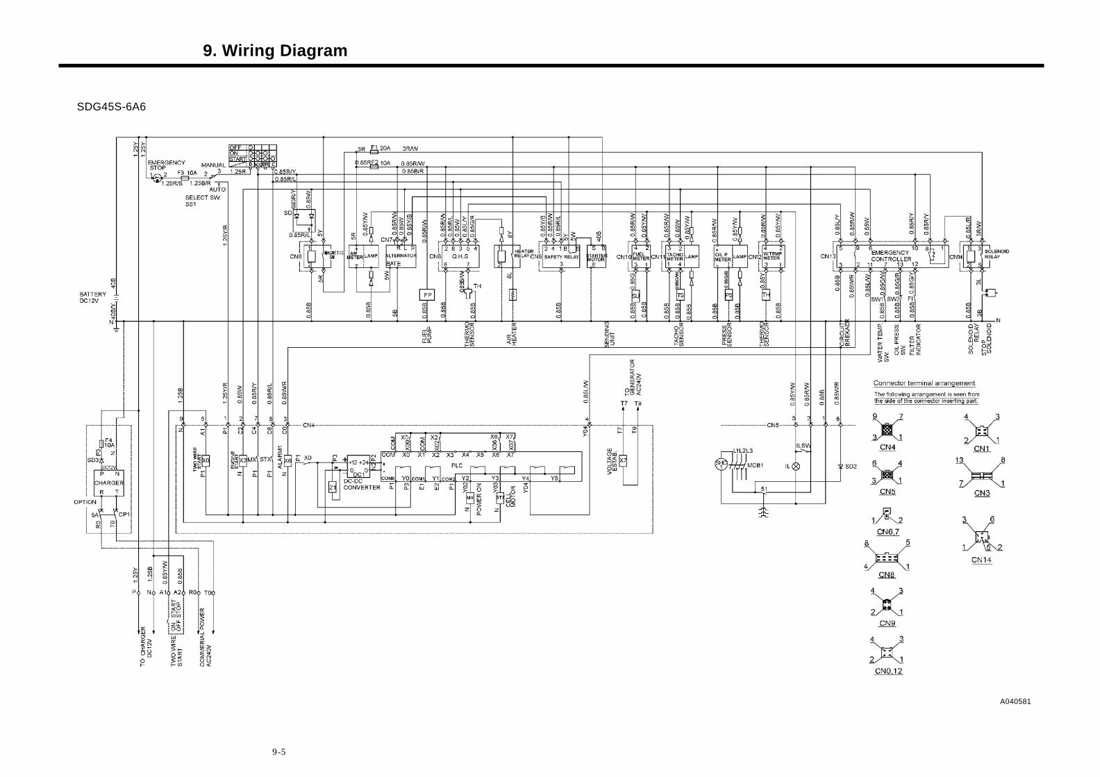
9. Wiring Diagram
9-5
SDG45S-6A6
A040581
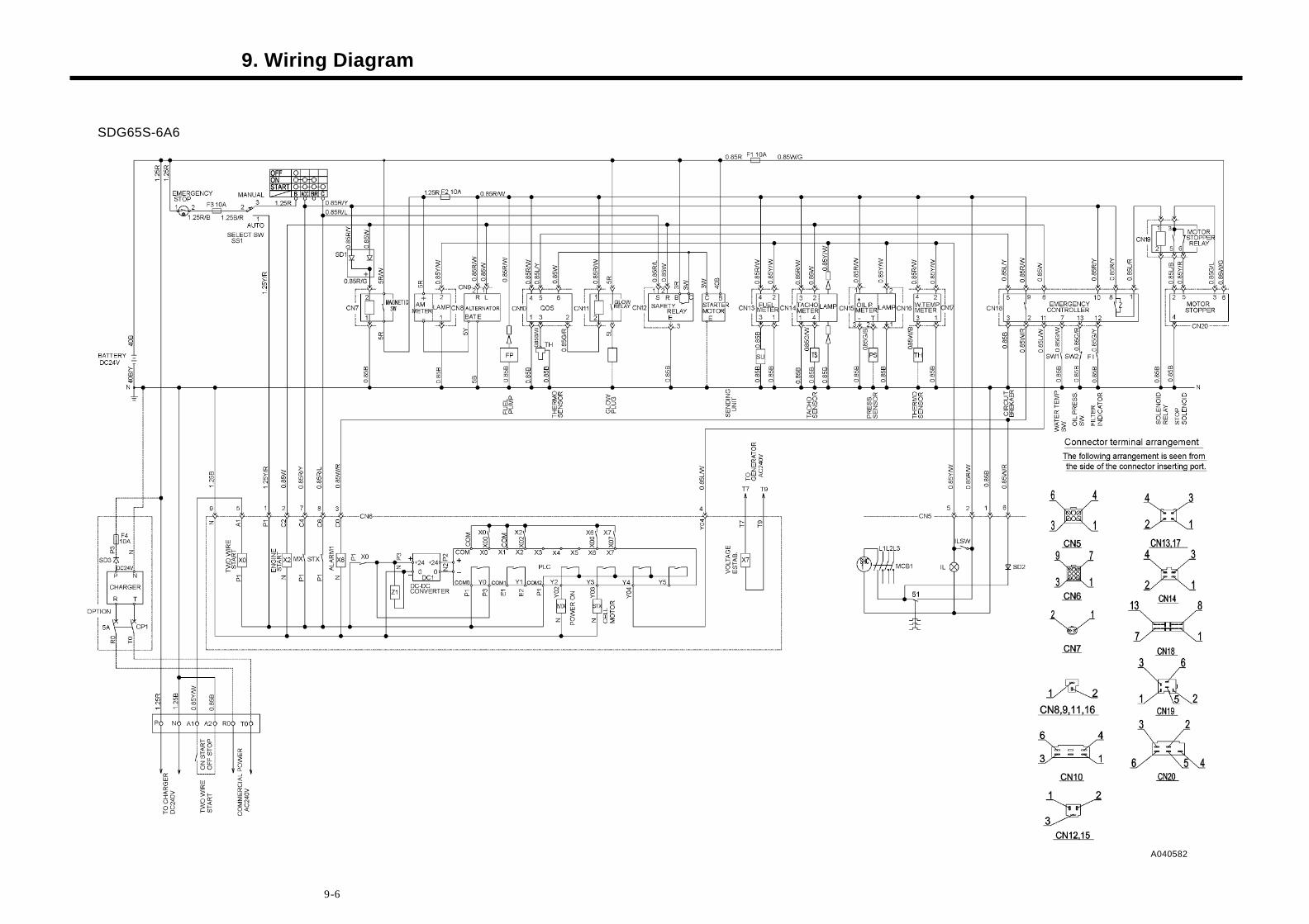
9. Wiring Diagram
9-6
SDG65S-6A6
A040582
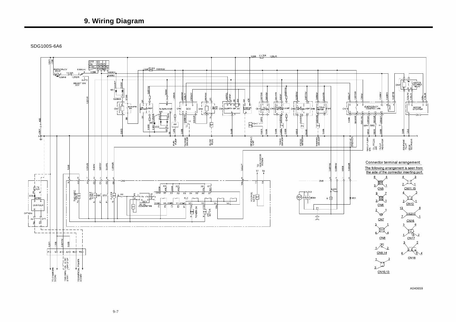
9. Wiring Diagram
9-7
SDG100S-6A6
A040659