Embed Size (px)
Citation preview

8/13/2019 Airlocks Ppt 2005-02-18 Dgl
http://slidepdf.com/reader/full/airlocks-ppt-2005-02-18-dgl 1/35
Airlocks
Field Operator Certification
Airlocks
8/13/2019 Airlocks Ppt 2005-02-18 Dgl
http://slidepdf.com/reader/full/airlocks-ppt-2005-02-18-dgl 2/35
Airlocks
13/02/2014Field Operator Certification 2
Lesson Objectives
1. State the purpose of Airlocks
2. State the different types of Airlocks used in cement
manufacturing
3. Explain the principle of operation for each type of Airlock4. State the applications for Airlocks in cement manufacturing
5. Describe the running & static inspections for each type of
Airlock
6. Describe the troubleshooting for common Airlock problems
7. Identify safety hazards associated with the operation of
Airlocks
8. Perform running & static inspections on Airlocks (OJT)

8/13/2019 Airlocks Ppt 2005-02-18 Dgl
http://slidepdf.com/reader/full/airlocks-ppt-2005-02-18-dgl 3/35
Airlocks
13/02/2014Field Operator Certification 3
Objective 1 - Purpose
To control the flow of
solids & fluids from one
process stream to
another.

8/13/2019 Airlocks Ppt 2005-02-18 Dgl
http://slidepdf.com/reader/full/airlocks-ppt-2005-02-18-dgl 4/35
Airlocks
13/02/2014Field Operator Certification 4
Objective 2 – Types of Airlocks

8/13/2019 Airlocks Ppt 2005-02-18 Dgl
http://slidepdf.com/reader/full/airlocks-ppt-2005-02-18-dgl 5/35
Airlocks
13/02/2014Field Operator Certification 5
Objective 2 – Types of Airlocks
Rotary Valves
Tipping / Gate
Obturator Valves
Pneumatic Pinch Valves

8/13/2019 Airlocks Ppt 2005-02-18 Dgl
http://slidepdf.com/reader/full/airlocks-ppt-2005-02-18-dgl 6/35
Airlocks
13/02/2014Field Operator Certification 6
Principle of Operation
Rotary Valve
Cast iron machined casing
within which multi vane
rotor revolves
Tight tolerances between
rotor & casing are critical in
maintaining proper seal
Material introduced into
Rotary Valve through an
inlet flange located on top
8/13/2019 Airlocks Ppt 2005-02-18 Dgl
http://slidepdf.com/reader/full/airlocks-ppt-2005-02-18-dgl 7/35
8/13/2019 Airlocks Ppt 2005-02-18 Dgl
http://slidepdf.com/reader/full/airlocks-ppt-2005-02-18-dgl 8/35
Airlocks
13/02/2014Field Operator Certification 8
Principle of Operation
Rotary Valve (cont’d)
Material evacuated from bottom of Rotary Valve once
pockets pass into open discharge point
Material falls by gravity through discharge flange intodownstream equipment
Rotary Valve can be driven at constant speed for
continuous evacuation of material at controlled rate
Can also be driven at variable speeds allowing RotaryValve to be used as material feeder

8/13/2019 Airlocks Ppt 2005-02-18 Dgl
http://slidepdf.com/reader/full/airlocks-ppt-2005-02-18-dgl 9/35
Airlocks
13/02/2014Field Operator Certification 9
Principle of Operation
Rotary Valve (cont’d)
Visualize the operation of revolving
doors commonly used in hotels &
other building entrances
Principle of operation is the same -
“controlled flow of solids & fluids
from one stream to another”
People enter or exit building while atthe same time reduce energy losses
associated with heating or air
conditioning

8/13/2019 Airlocks Ppt 2005-02-18 Dgl
http://slidepdf.com/reader/full/airlocks-ppt-2005-02-18-dgl 10/35
Airlocks
13/02/2014Field Operator Certification 10
Principle of Operation – Tipping
Valves
Fabricated or cast body
with an inlet & outlet
flange connected between
two process streams
Between the two flanges,
internal gate is used to
control flow of material
between two streams

8/13/2019 Airlocks Ppt 2005-02-18 Dgl
http://slidepdf.com/reader/full/airlocks-ppt-2005-02-18-dgl 11/35
Airlocks
13/02/2014Field Operator Certification 11
Principle of Operation
Tipping Valves (cont’d)
Material gate commonly fixed to pivoting shaft supported
by bearing assembly at each end
Material introduced into Tipping Valve through inlet flange Material accumulates above gate until either mechanical
drive forces gate open, or mass of material above gate
overcomes externally mounted counterweight which in
turn forces gate to open
In both cases material is released through Tipping Valves
discharge flange into downstream equipment

8/13/2019 Airlocks Ppt 2005-02-18 Dgl
http://slidepdf.com/reader/full/airlocks-ppt-2005-02-18-dgl 12/35
Airlocks
13/02/2014Field Operator Certification 12
Principle of Operation
Tipping Valves (cont’d) Those with mechanical
drives are commonly openfor predetermined period oftime or until ideal materiallevel is achieved
Those using external
counterweight open onlylong enough to releaseenough material to resetcounterweight
2 commonly used in seriesto ensure proper Airlock
One of 2 gates remainsclosed at all times ensuringpositive seal between 2streams

8/13/2019 Airlocks Ppt 2005-02-18 Dgl
http://slidepdf.com/reader/full/airlocks-ppt-2005-02-18-dgl 13/35
Airlocks
13/02/2014Field Operator Certification 13
Principle of Operation
Tipping Valves (cont’d)
Visualize the operation ofdouble doors commonlyused in shopping malls &other building entrances
Principle of operation is thesame - “controlled flow ofsolids & fluids from onestream to another”
People enter or exitbuilding with doors closingbehind them before doorsare opened ahead

8/13/2019 Airlocks Ppt 2005-02-18 Dgl
http://slidepdf.com/reader/full/airlocks-ppt-2005-02-18-dgl 14/35
Airlocks
13/02/2014Field Operator Certification 14
Principle of Operation
Obturator Valve
Consists of 2 molded & pre-
stressed elastomer diaphragms
connected together at sides &
inlet flange
Open area at bottom adjusted by
2 positioning rods that ensure
proper orientation of side
diaphragms
Absence of material, negative
static pressure of upstream
vessel forces 2 diaphragms
together creating tight seal,
isolating upper & lower streams

8/13/2019 Airlocks Ppt 2005-02-18 Dgl
http://slidepdf.com/reader/full/airlocks-ppt-2005-02-18-dgl 15/35
8/13/2019 Airlocks Ppt 2005-02-18 Dgl
http://slidepdf.com/reader/full/airlocks-ppt-2005-02-18-dgl 16/35
Airlocks
13/02/2014Field Operator Certification 16
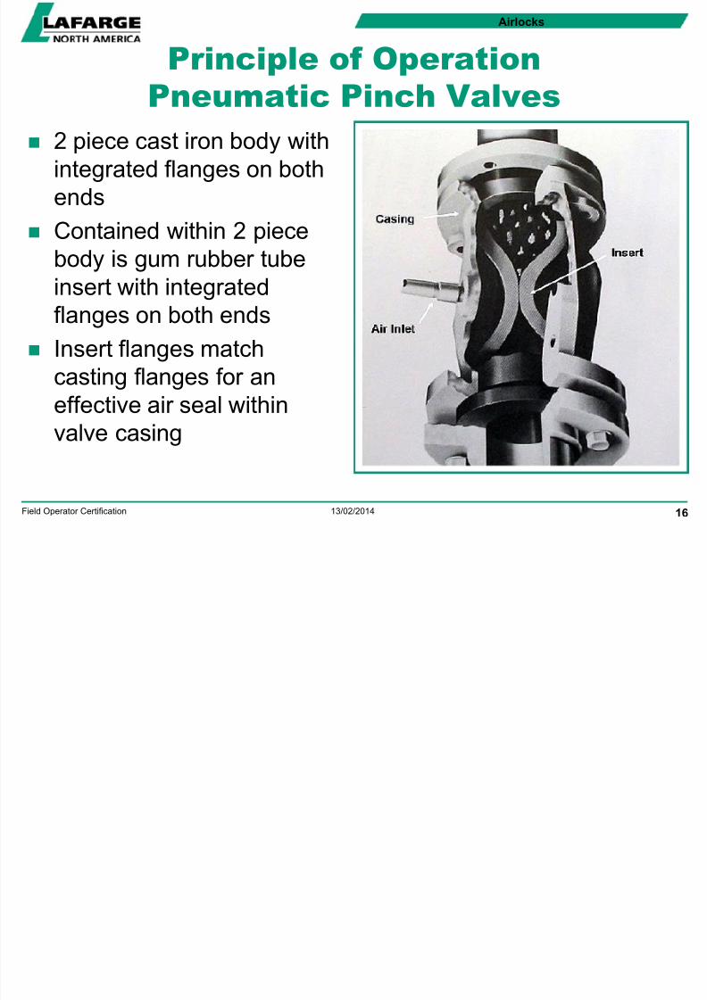
Principle of Operation
Pneumatic Pinch Valves
2 piece cast iron body with
integrated flanges on both
ends
Contained within 2 piece
body is gum rubber tube
insert with integrated
flanges on both ends
Insert flanges match
casting flanges for aneffective air seal within
valve casing

8/13/2019 Airlocks Ppt 2005-02-18 Dgl
http://slidepdf.com/reader/full/airlocks-ppt-2005-02-18-dgl 17/35
Airlocks
13/02/2014Field Operator Certification 17
Principle of Operation
Pneumatic Pinch Valves (cont’d)
Commonly installed in round duct between 2 process
streams to provide isolation & or flow control similar to
installation of Tipping Valve or Rotary Valve
To provide isolation, compressed air is introduced into
void between 2 piece assembled casting & gum rubber
insert

8/13/2019 Airlocks Ppt 2005-02-18 Dgl
http://slidepdf.com/reader/full/airlocks-ppt-2005-02-18-dgl 18/35
Airlocks
13/02/2014Field Operator Certification 18
Principle of Operation
Pneumatic Pinch Valves (cont’d)
As pressure is increased from atmospheric to typically 50
psi, rubber tube insert is forced to collapse within casting
Collapsed insert creates a seal between upper & lower
process streams isolating the two from one another

8/13/2019 Airlocks Ppt 2005-02-18 Dgl
http://slidepdf.com/reader/full/airlocks-ppt-2005-02-18-dgl 19/35
Airlocks
13/02/2014Field Operator Certification 19
Principle of Operation
Pneumatic Pinch Valves (cont’d)
Typical configuration - operation controlled by level
detectors in process stream
When target level is reached, compressed air vented fromPinch Valve & rubber tube opens (material flows)
Once level detectors clear, Pinch Valve closes, isolating
system
Pinch Valve can be configured for flow control by applyingvariable pressure through controller to Pinch Valve

8/13/2019 Airlocks Ppt 2005-02-18 Dgl
http://slidepdf.com/reader/full/airlocks-ppt-2005-02-18-dgl 20/35
Airlocks
13/02/2014Field Operator Certification 20
Objective 5 - Applications
Pneumatic PinchValves
Dust Collectors
Cyclones
Feeders Pneumatic
Transport
RotaryValves
Tipping / GateValves
ObturatorValves
Dust Collectors
Cyclones
ClinkerCooler Under
Grate
Compartments
Gravel Bed
Filters Vertical Roller
Mill Feed &
Rejects Chute
HES Rejects
Chutes
Dust Collectors
Cyclones
Dust Collectors
Cyclones
Slurry FlowControl

8/13/2019 Airlocks Ppt 2005-02-18 Dgl
http://slidepdf.com/reader/full/airlocks-ppt-2005-02-18-dgl 21/35
Airlocks
13/02/2014Field Operator Certification 21
Objective 6 - Inspections
Running Inspection… Rotary Valves
Tipping Valves
Obturator Valves
Pinch Valves
Static Inspection … Rotary Valves
Tipping ValvesObturator Valves
Pinch Valves

8/13/2019 Airlocks Ppt 2005-02-18 Dgl
http://slidepdf.com/reader/full/airlocks-ppt-2005-02-18-dgl 22/35
Airlocks
13/02/2014Field Operator Certification 22
Objective 7 - Troubleshooting
Pneumatic PinchValves
Rotary Valve
will not start
Noisy drive
Valve noisy
Packing seals
leaking
Bearings noisy
Product will notdischarge
RotaryValves
Tipping / GateValves
ObturatorValves
Valve will not
operate
Valve not
sealing
properly
Noisy drive
Valve
operation isnoisy
Bearings noisy
Valve will not
discharge
product
Valve will not
seal
Valve will not
discharge
product
Pinch Valve
will not isolate
material flow
Material does
not evacuate
from Pinch
Valve

8/13/2019 Airlocks Ppt 2005-02-18 Dgl
http://slidepdf.com/reader/full/airlocks-ppt-2005-02-18-dgl 23/35
Airlocks
13/02/2014Field Operator Certification 23
Objective 8 - Safety
Mechanically driven Airlocks can start & stop
automatically
Casing & internal material temps can be extremelyhot
External Tipping Valve arms can be under extreme
pressure from material above valve
Creates pinch point in many applications

8/13/2019 Airlocks Ppt 2005-02-18 Dgl
http://slidepdf.com/reader/full/airlocks-ppt-2005-02-18-dgl 24/35
Airlocks
13/02/2014Field Operator Certification 24
Objective 8 – Safety (cont’d)
Inspect all guards for damage & support integrity
regularly
Never attempt to remove build-up off componentswhile in operation
Keep clothing, fingers, hair, & other parts of body
away from drive components
Report all unsafe conditions or practicesimmediately

8/13/2019 Airlocks Ppt 2005-02-18 Dgl
http://slidepdf.com/reader/full/airlocks-ppt-2005-02-18-dgl 25/35
Airlocks
13/02/2014Field Operator Certification 25
Lesson Review
What is the purpose of an Airlock?
To control the flow of solids & fluids from one process
stream to another

8/13/2019 Airlocks Ppt 2005-02-18 Dgl
http://slidepdf.com/reader/full/airlocks-ppt-2005-02-18-dgl 26/35
Airlocks
13/02/2014Field Operator Certification 26
Lesson Review
List 4 types of Airlocks commonly found in cement
manufacturing
1. Rotary Valves2. Tipping Valves – Gravity, Pneumatic, Hydraulic, Motor
Driven
3. Pinch Valves
4. Obturator Valves

8/13/2019 Airlocks Ppt 2005-02-18 Dgl
http://slidepdf.com/reader/full/airlocks-ppt-2005-02-18-dgl 27/35
Airlocks
13/02/2014Field Operator Certification 27
Lesson Review
Describe the unique limitation to the application of
an Obturator Valve
Can only be used in applications where the upperprocess stream is under negative pressure
Common applications are Dust Collectors & Cyclones

8/13/2019 Airlocks Ppt 2005-02-18 Dgl
http://slidepdf.com/reader/full/airlocks-ppt-2005-02-18-dgl 28/35
Airlocks
13/02/2014Field Operator Certification 28
Lesson Review
What real world application best illustrates the
operation of a Rotary Valve, and why?
Rotary Valve concept can be visualized in the real world
through the operation of revolving doors commonly usedin hotels & other building entrances
Principle of operation is the same - “the controlled flow
of solids & fluids from one stream to another”
In this case people entering or exiting the building whileat the same time reducing energy losses associated with
heating or air conditioning

8/13/2019 Airlocks Ppt 2005-02-18 Dgl
http://slidepdf.com/reader/full/airlocks-ppt-2005-02-18-dgl 29/35
Airlocks
13/02/2014Field Operator Certification 29
Lesson Review
What real world application best illustrates the
operation of a Tipping Valve, and why?
Tipping Valve concept can be visualized in the real world
through the operation of double doors commonly used inshopping malls & other building entrances
The principle of operation is the same - “the controlled
flow of solids & fluids from one stream to another”
In this case people entering or exiting the building withdoors closing behind them before the doors are opened
ahead
Ai l k

8/13/2019 Airlocks Ppt 2005-02-18 Dgl
http://slidepdf.com/reader/full/airlocks-ppt-2005-02-18-dgl 30/35
Airlocks
13/02/2014Field Operator Certification 30
Lesson Review
How does a pinch valve control the flow of solids
and fluids between two streams?
The pinch valve uses compressed air to collapse theinsert within the valve body isolating the two streams
from one another.

8/13/2019 Airlocks Ppt 2005-02-18 Dgl
http://slidepdf.com/reader/full/airlocks-ppt-2005-02-18-dgl 31/35
Ai l k

8/13/2019 Airlocks Ppt 2005-02-18 Dgl
http://slidepdf.com/reader/full/airlocks-ppt-2005-02-18-dgl 32/35
Airlocks
13/02/2014Field Operator Certification 32
Lesson Review
Describe 5 inspection points for each of the 4 types
of Airlocks described in this module
As per Inspection information
Airlocks

8/13/2019 Airlocks Ppt 2005-02-18 Dgl
http://slidepdf.com/reader/full/airlocks-ppt-2005-02-18-dgl 33/35
Airlocks
13/02/2014Field Operator Certification 33
Lesson Review
Describe 3 conditions that could explain why
product would not discharge from a Rotary Valve
As per Troubleshooting information
Airlocks

8/13/2019 Airlocks Ppt 2005-02-18 Dgl
http://slidepdf.com/reader/full/airlocks-ppt-2005-02-18-dgl 34/35
Airlocks
13/02/2014Field Operator Certification 34
Lesson Review
Describe 3 conditions that could explain why a
Pinch Valve would not isolate a material flow
As per Troubleshooting information
Airlocks

8/13/2019 Airlocks Ppt 2005-02-18 Dgl
http://slidepdf.com/reader/full/airlocks-ppt-2005-02-18-dgl 35/35
Airlocks
Lesson Review
Describe 3 safety hazards associated with any of
the Airlocks described in this module
As per Safety information


![Impact Assessments Director’s Guideline [DGL 22/20]](https://img.pdfslide.us/doc/110x75/6169d5cf11a7b741a34be531/impact-assessments-directors-guideline-dgl-2220.jpg)