Embed Size (px)
Citation preview

AIRLINE REQUIREMENTS FOR DESIGN TENANT DEVELOPMENT GUIDELINES
2
Copyright ©2015 by Denver International Airport
All rights reserved No part of this manual may be reproduced or transmitted in any form or by any means, electronic or mechanical, including photocopying, recording, or by any information storage and retrieval system, without the permission in writing from the publisher. Printed in the United States of America

3
Table of Contents The Jeppesen Terminal .................................................................................................................................................................................................................... 5
Terminal East and West Sides ...................................................................................................................................................................................................... 6 Levels of the Terminal ................................................................................................................................................................................................................. 6 Door Numbers ............................................................................................................................................................................................................................. 6
Hotel and Transit Center ................................................................................................................................................................................................................. 7
Airline Customer Service Counters .................................................................................................................................................................................................. 8 Customer Service Counter Leasehold .......................................................................................................................................................................................... 9 Passenger Queuing .................................................................................................................................................................................................................... 10 Power and Communication Cabling .......................................................................................................................................................................................... 10 Self-Service Units ....................................................................................................................................................................................................................... 11
Support Facilities ........................................................................................................................................................................................................................... 12 Airline Customer Service Offices ............................................................................................................................................................................................... 12 Baggage Service Offices (BSO) ................................................................................................................................................................................................... 12 Baggage Claim Carousels ........................................................................................................................................................................................................... 13 Over-Sized Baggage Claim Areas ............................................................................................................................................................................................... 13 Baggage Make-Up Areas ............................................................................................................................................................................................................ 14
Security Screening Checkpoints (SSCP) ......................................................................................................................................................................................... 15
The Gates – A, B, and C .................................................................................................................................................................................................................. 16
Airline Distribution across the Concourses.................................................................................................................................................................................... 17 Concourse A ........................................................................................................................................................................................................................... 17
Concourse B ........................................................................................................................................................................................................................... 19
Concourse C ........................................................................................................................................................................................................................... 19
Boarding Gates .............................................................................................................................................................................................................................. 20 Podiums and Backwalls.............................................................................................................................................................................................................. 20 LCD Monitors on the Backwall ................................................................................................................................................................................................... 20 Holdrooms ................................................................................................................................................................................................................................. 21 Gate Information Display Systems (GIDS) ................................................................................................................................................................................. 22
Emergency Communications Systems or, the Advantages and Disadvantages of LCD Monitors (GIDS) .............................................................................. 23

4
Signage Program ............................................................................................................................................................................................................................ 24 Roadway Signage ....................................................................................................................................................................................................................... 25 Curbside Signage ....................................................................................................................................................................................................................... 26 Airline Customer Service Counter Backwall Signage ................................................................................................................................................................. 27 Signage in the Customer Service Counter Queue Area ............................................................................................................................................................. 28 Wayfinding Signage ................................................................................................................................................................................................................... 28 Gate Identification – Blade Signs ............................................................................................................................................................................................... 29 Gate Podium and Backwall Signage ........................................................................................................................................................................................... 30 Passenger Loading Bridge Signage (exterior) ............................................................................................................................................................................ 31 Passenger Loading Bridge Signage and Graphics (interior) ....................................................................................................................................................... 31 Outlying Building Signage .......................................................................................................................................................................................................... 31 Joint-Use Cargo Building (JUC) ................................................................................................................................................................................................... 32

5
THE JEPPESEN TERMINAL Its unique layout and defining terms What is commonly known at DEN as “the Terminal” is officially named the Jeppesen Terminal in honor of Elrey B. Jeppesen, a businessman and aviation pioneer, whose “Jepp” navigational maps and charts are standard equipment in most commercial airline cockpits around the world.
In February 1991, Denver City Council officially named the city's new airport terminal for Jepp. A Rocky Mountain News editorial said, "There may be others whose flying deeds and endowments make them comparably strong candidates for airport naming – but you could probably count them on a sloth's foot." The editorial concluded by saying that naming DIA's terminal after Jepp would correct the deficiency of people outside of aviation circles not knowing about him. The terminal honor would "close the gap between legacy and legend," the editorial said. It would close the gap "between huge modern airliners that trust to Jepp charts and the days when you could feel the wind on your face."
Jepp was the first passenger to arrive when DIA opened on Feb. 28, 1995. He died less than two years later, in November 1996. Today pilots all over the world use Jeppesen Airway Manuals.
Figure 1 – Elrey B. Jeppesen Statue
Figure 2 – DEN Terminal and Hotel

6
Terminal East and West Sides The Terminal was designed with two sides to the one building – East and West. Approximately half our airlines are located on the East Side and half our airlines are located on the West Side. Because they are two sides of the one building, a passenger that mistakenly goes to the West Side for an airline that is actually located on the East Side is not at a great disadvantage. The customer service counters on the East Side are a short walk through the Great Hall from the customer service counters on the West Side.
In the north-south direction, the Terminal is divided into 3 building modules. We call them Mods, and they are numbered from north to south. So, the northern-most Mod on the West Side is Mod 1-W. The southern-most Mod on the East Side is Mod 3-E.
Levels of the Terminal The Terminal was designed in such a way that there are 6 Levels. Not all Levels are accessible by the passenger. Those Levels that are important to the passenger are:
• Level 6 – this is the Departures Level with curbside drop-off and containing all Airline Customer Service Counters
• Level 5 – this is the Baggage Claim Level. Outside the doors on this Level are the majority of Ground Transportation services such as taxis, limousines, shuttles to on-airport parking, shuttles to rental car companies, some shared ride services, crew shuttles, shuttles to off-airport parking
• Level 4 – this is the Arrivals Level where most arriving passengers await curbside pick-up in private vehicles by friends or family
Levels 1 thru 5 also give access to the Parking Structure located on either side of the Terminal.
Door Numbers A good way to identify where you are, and maybe where you want to be dropped off or picked up, is by the door numbers. All the doors on the West Side are numbered with even numbers (for example, on the 6th Level, Door 600 at the far north end, 602, 604, 606 working our way south). All the doors on the East Side are numbered with odd numbers (601 at the far north end, 603, 605, 607 working our way south). The doors on the lower levels are numbered likewise – 500 series on Level 5, 400 series on Level 4, etc.
Figure 3 – East Side, Level 6 Departures
Figure 4 – East Side, Level 6 Exterior Door

7
HOTEL AND TRANSIT CENTER Just south of the Jeppesen Terminal, sits our newest addition to the Terminal Complex, the Hotel and Transit Center. The Hotel opens in late 2015 and will be operated as a Westin Hotel. It has 519 guest rooms with extensive conference center facilities. The Hotel sits over an open-air plaza that will encourage and stage public events in order to draw patrons to the airport as a destination node from the rest of the metropolitan area. To further serve that purpose and to offer another mode of transit after arriving on a flight to Denver, the Regional Transportation District (RTD) will begin commuter rail service to the Transit Center at DEN in early 2016. Electric trains will run from DEN to downtown Denver’s Union Station, serving stops in neighborhoods along the way. DEN will now join the many other world class airports with train service just a short walk from your airline’s baggage claim carousel to the central core of its host city. The plaza will be on a level equal to Level 5 of the Terminal. You truly will walk out of Level 5 with your bags, onto the Plaza, down the escalator to Level 1 and board either the RTD commuter rail service on the train platform or RTD’s commuter bus service serving the entire Denver metropolitan area.
Figure 5 – Hotel
Figure 6 – Hotel and Transit Center

8
AIRLINE CUSTOMER SERVICE COUNTERS Under original construction, Airline Customer Service Counters at DEN were standard and were provided by the airport. Over the years, airlines have asked for and received permission to replace the standard counters with custom, airline-specific designs, sometimes incorporating Self-Service Units. The Customer Service Counter area that your airline has been assigned may or may not have customer service counters remaining from original construction or they may be remaining from a previous airline. In any case, the airline may use the counters that are there or submit a custom design for new counters to the DEN PM for approval. The approval process for the Customer Service Counter Area may or may not require a formal submittal to the DEN Design Review Committee (DRC). The approval process remains at the discretion of the Chairman of the DEN DRC. The DRC is described in a separate document.
Figure 7 – United Counter
Figure 8 – British Airways Counter
Figure 9 – Southwest Counter
9
Customer Service Counter Leasehold The minimum Customer Service Counter Leasehold utilizing base building service counter shells comprises two agent positions (in the one service counter shell) with half a bagwell on each side. Due to the modularity of the Terminal design, the width of this minimum service counter leasehold is 10’-0” from bagwell centerline to bagwell centerline. Some counter/bagwell combinations are unique in dimension for various reasons, but the majority of the existing base building service counters follow the 10’ module and are approximately 6’-8¾” in width. The base building bagwells are commonly 3’-3¼” in width. The leasehold area involved in a service counter area is measured from the centerline of the backwall to the passenger side face of the base building service counter. To gauge the area involved in the customer service counter footprint, the standard distance from the centerline of the backwall to the outside face of the base building service counter is 12’-0”, so the minimum leasehold at the service counter is approximately 120 sf for two agent positions.
If a customer service counter shell includes a millwork insert in place, containing the agent work surface and the shelves, drawers and doors required for their operation, the airline can use the insert. Otherwise, the airline must provide their own millwork insert to fit into the service counter shell to provide the countertop, the shelves, and the drawers necessary to meet the airline’s functional customer service counter needs. If the airline should relocate, they may leave or take the insert upon vacating the subject service counter.
The base building service counters each have a removable front panel for access to the back of the insert and the equipment it contains. The power and communications cabling come up into the counter shell through the floor slab and are accessible in this space, after removing the face of the counter.
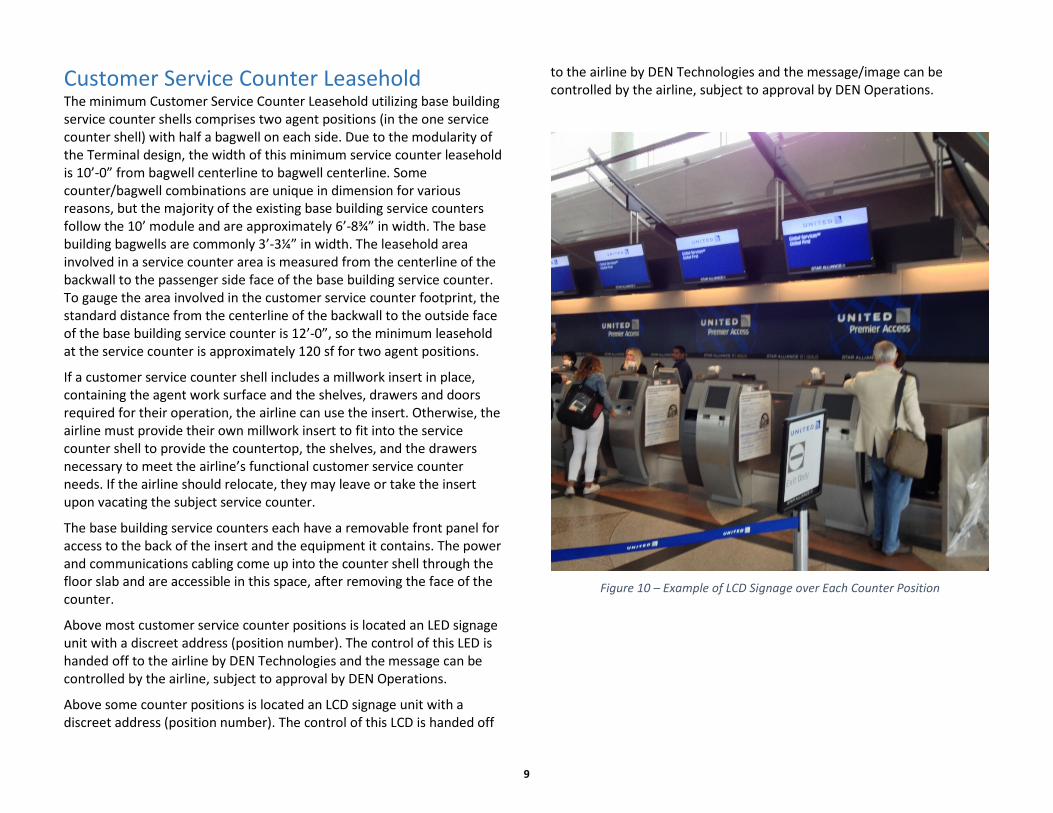
Above most customer service counter positions is located an LED signage unit with a discreet address (position number). The control of this LED is handed off to the airline by DEN Technologies and the message can be controlled by the airline, subject to approval by DEN Operations.
Above some counter positions is located an LCD signage unit with a discreet address (position number). The control of this LCD is handed off
to the airline by DEN Technologies and the message/image can be controlled by the airline, subject to approval by DEN Operations.
Figure 10 – Example of LCD Signage over Each Counter Position

10
Passenger Queuing Stanchion placement for passenger queueing is limited by the airline’s leasehold limits on the north and south edges of the leasehold extended into the passenger queueing area, i.e. an airline’s stanchions cannot extend north or south beyond the extended leasehold boundaries (generally centerlines of bagwells). The depth of the passenger queueing area and the extent of stanchions away from the face of the service counters is generally limited to three modules of colored granite surrounded by a black granite stripe in the flooring (approximate depth of passenger queueing area equals 24’-0”). This control leaves two modules of colored granite surrounded by a black granite stripe outside of the stanchions for passenger circulation in the north-south direction (approximate width of passenger circulation area equals 16’-0”).
Figure 11 – Passenger Queuing
Power and Communication Cabling The power supplied to each two-position service counter during original construction was three power circuits. Conduits for communications cabling were installed empty. Each airline to occupy a new, unused set of service counter positions contracted with DEN Technologies for communication cabling depending on their individual airline needs. Therefore, each existing service counter position may have any number of combinations of data and voice cabling of varying types and sizes. It is imperative that the airline contact DEN Technologies for assistance with a field survey of existing cable in place.
Figure 12 – Power and Comm Cabling to a Typical Counter Shell

11
Self-Service Units As the use of Self-Service Units has increased over the years, these installations generally take the form of one of the following:
• In-Counter SSUs installed within or on the service counter millwork, thus requiring no special construction or underfloor access other than what is already in place in and for the counter;
• Freestanding SSUs Adjacent to the Service Counter – this category of installation places the SSUs in front of the existing counter units taking advantage of the use of free-standing units requiring no significant modifications to the existing counters, but still allowing the airline to take advantage to the existing power and communications cabling infrastructure that exists in the existing service counter;
• Freestanding SSUs in the queue area in front of the airline’s service counters.
These three alternative locations are the only locations that will be considered by consent. In the past, we have denied an airline’s request to place SSUs across from the service counters against the marble walls near the exit doors. The reason for the denial is merely the fact that queueing in front of an SSU can become cumbersome and would tend to block the main north-south passenger circulation. In all airline requests for approval of queue area layouts, the primary gauge of measurement taken by the reviewers is customer service, passenger circulation and access in case of emergency services which may be required.
If an airline’s leasehold includes a major portion of half a Mod, the airline may request airport consideration of using the Alcove against the exterior window wall, across from their counters, for the installation of freestanding SSUs. The request for use of this space would be proposed to the airline’s DEN PM or the DEN Property Manager for Airlines. The review process for a request such as this would include the sections of Terminal Operations, Commercial, and the DRC.
Figure 13 – Self-Service Units

12
SUPPORT FACILITIES Airline Customer Service Offices The basic design of the Terminal on Level 6 provides for office space directly behind the backwall of the customer service counter area. Much of this office space is being used by airlines as their customer service office space. Some is being used by the City and County of Denver’s Department of Aviation, responsible for operating the airport. This supporting space is generally accessible by a door or doors in the backwall itself (depending on the layout of the baggage belt system along the customer service counter backwall), or by doors at the north and south end of each Mod, with almost all doors leading into a corridor system serving the offices and ancillary spaces.
Baggage Service Offices (BSO) Accompanying the Baggage Claim Units on Level 5 of the Terminal are office spaces generally dedicated to airline use. These spaces enable an airline to have their baggage services as close to their assigned baggage claim units as possible. During original construction, these offices were generally fitted with counters similar in design to the customer service counters one level above. Over the years of use, many airlines have changed out these spaces with custom counter layouts and designs.
Figure 14 – Baggage Service Office

13
Baggage Claim Carousels Level 5 contains 18 Baggage Claim Carousels fed from the Baggage Make-Up Area on Level 3 of the Terminal. Airline tugs and carts deliver the arriving baggage from the aircraft on the Concourse apron, down into the baggage tunnels, to the conveyors on Level 3 of the Terminal. The conveyors deliver the bags to the Baggage Claim Carousels on Level 5 of the Terminal.
Figure 15 – Baggage Claim Carousel
Over-Sized Baggage Claim Areas Against the wall separating the Baggage Claim Carousels from the Baggage Service Office area are Over-Sized Baggage Claim Areas in two forms – sloped slide plates; and ski and golf club carousel. Over-Sized Baggage is also delivered on airline tugs and carts from the aircraft on the Concourse apron, through the baggage tunnels, to the Over-Sized tub lifts on Level 3 of the Terminal. The tub lifts deliver the over-sized baggage up to Level 5 of the Terminal, into non-public space behind the Over-Sized Baggage Claim Areas. At this point, airline personnel or airline contractors place the over-sized baggage either onto the sloped slide plates opening to the public baggage claim area or into the ski and golf club carousel where it makes its way around the loop to the public baggage claim area for pickup by the passenger.
Figure 16 – Over-sized Baggage Claim Carousel (Skis and Golf Clubs)

14
Baggage Make-Up Areas When the passenger’s baggage is placed on the take-away baggage belt against the backwall behind the customer service counter, the conveyor system eventually delivers the bag to the assigned carousels on Level 3 of the Terminal. At this point, the airline staff picks the bags from the
carousel and place in the appropriate cart to be tugged to the Concourse through the baggage tunnel system.
Figure 17 – Arriving Baggage Conveyors
Figure 18 – Departing Baggage Carousels

15
SECURITY SCREENING CHECKPOINTS (SSCP) DEN currently has three separate Security Screening Checkpoints – one at the south end of Level 5 of the Terminal; one at the north end of Level 5 of the Terminal; and one SSCP as you walk north on Level 6 from the Terminal toward the pedestrian bridge to Concourse A. There is space set aside in the Hotel and Transit Center facility for a fourth SSCP. It will be built out when passenger growth requires further screening capacity.
The Departing Passenger, having checked in with his airline and dropped whatever bags he wishes to check, makes his way to one of the Security Screening Checkpoints to be screened by the Transportation Security Administration (TSA). All SSCPs provide a route to access any and all gates, albeit by slightly different routes.
The SSCPs in the north and south ends of the Terminal direct the screened passenger down one level to the Terminal Train Station on Level 4. This train is an Automated Guideway Transit System (AGTS) and travels to and from the Terminal serving all three Concourses on a “pinched-loop” system.
The SSCP on Level 6, known as “Bridge Security,” directs screened passengers across on the lower level of the bridge over Taxiway Sierra Alpha (SA – the taxiway on the South Side of Concourse A). It is common that passengers on the airlines with A-Gates would use this SSCP and the Bridge over to Concourse A. They don’t have to use the train. But passengers on the airlines on Concourse B and Concourse C will also use this SSCP and the Bridge over to Concourse A, knowing that once they get across the bridge, they can take the elevator down to the Concourse A Train Station and continue on the train to either Concourse B or Concourse C.
Figure 19 – North Security Screening Checkpoint

16
THE GATES – A, B, AND C Each on its own concourse The terminology that has been used since the original design of DEN is that the buildings containing the Holdrooms and the Gates are called Concourses. This may be different terminology to an airline that is new to DEN, but we are gradually modifying the lexicon such that our wayfinding signage will begin to refer to the passenger’s destination to board his flight as “Gates” such as “To All Gates, All Airlines,” “Gates B15 thru B36,” “To All B Gates” rather than “To Concourse B.”
All three Concourses accessed by a “train” from the Jeppesen Terminal When a passenger has checked their baggage with their airline, and they have their boarding passes (either from the airline service counter, the airline’s self-service units, or printed at home, or even visible on their smartphone), they proceed through the Security Screening Checkpoints and down to Level 4 of the Terminal, the Train Station. Here they will board DEN’s AGTS (Automated Guideway Transit System), the train, and travel out away from the Terminal to the Concourse containing their boarding – Concourse A for all A Gates, Concourse B for all B Gates, or Concourse C for all C Gates.
The only exception to this procedure is if you go through A Security located on Level 6 beyond the north end of the Terminal. After security processing at A Security, you are able to walk across the “Bridge” directly to Concourse A. At this point, you can walk to any A Boarding Gates, or you can take an elevator down to the Concourse A Train Station, board the train and continue on to Concourses B or C.
Figure 20 – Train Serving Terminal and Concourses
Figure 21 – Terminal/Concourse Configuration
17
AIRLINE DISTRIBUTION ACROSS THE CONCOURSES Concourse A is the concourse containing all the international arrivals gates because it has the circulation infrastructure to allow a flight from a destination outside the borders of the United States to disembark its passengers so they can flow directly across the upper level of the bridge from Concourse A to the Terminal and down into Passport Control, Customs and Immigration Control in the very north end of the Terminal. These arriving international passengers either immediately recheck onto connecting flights or pass out into the Terminal to be met by friends and family or to connect onto the various modes of Ground Transportation available on Level 5 of the Terminal. All international arrivals must disembark their passengers at one of the international arrival gates on Concourse A or disembark at a hardstand with bussing service to one of the international arrival gates on Concourse A.
Concourse A
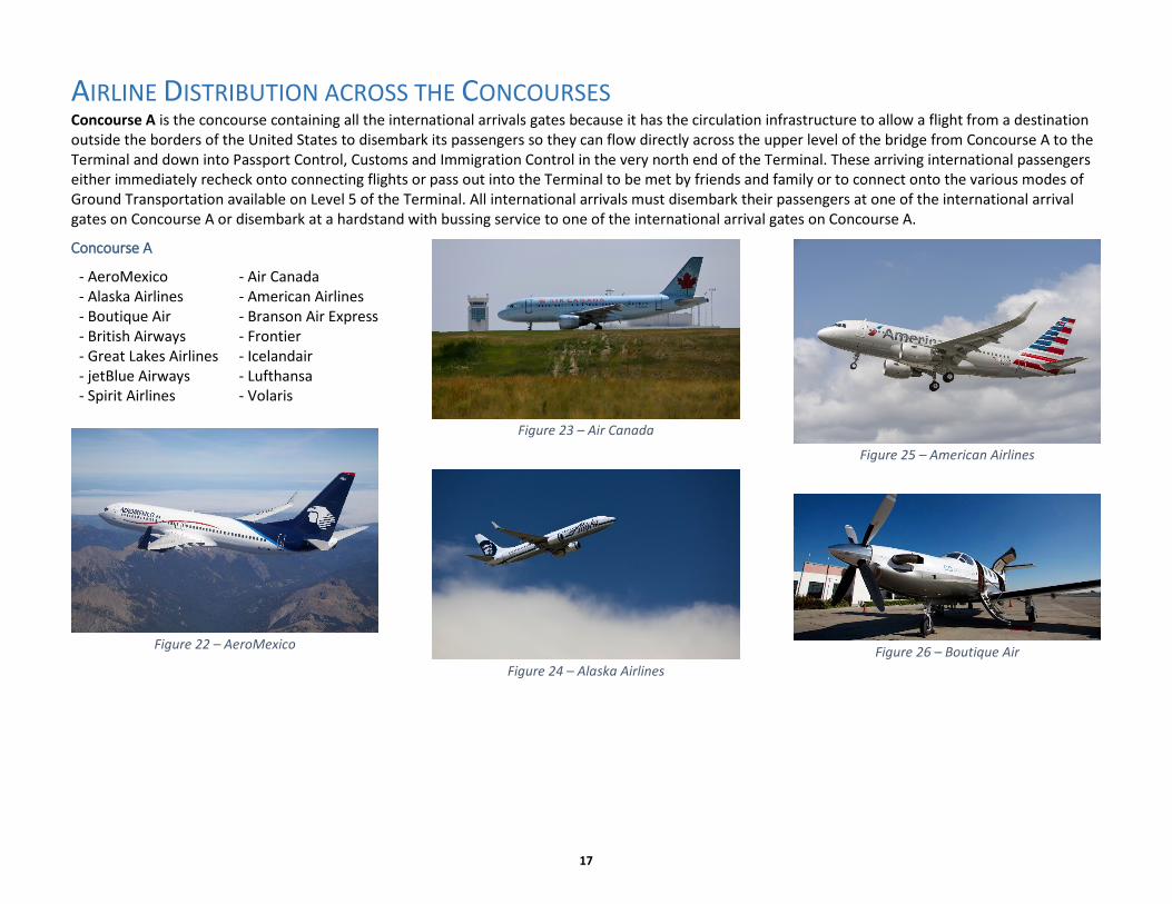
- AeroMexico - Air Canada - Alaska Airlines - American Airlines - Boutique Air - Branson Air Express - British Airways - Frontier - Great Lakes Airlines - Icelandair - jetBlue Airways - Lufthansa - Spirit Airlines - Volaris
Figure 22 – AeroMexico
Figure 23 – Air Canada
Figure 24 – Alaska Airlines
Figure 25 – American Airlines
Figure 26 – Boutique Air
18
Figure 27 – Branson Air Express
Figure 28 – British Airways
Figure 29 – Frontier
Figure 30 – Great Lakes
Figure 31 – Icelandair
Figure 32 – jetBlue
Figure 33 – Lufthansa
Figure 34 – Spirit
Figure 35 – Volaris

19
Concourse B
Figure 36 – United Airlines
Figure 37 – Airfield
Concourse C
Figure 38 – Delta
Figure 39 – Southwest

20
BOARDING GATES Podiums and Backwalls Each boarding gate at DEN has an existing podium and backwall set assigned for use by the airline. (Some podium and backwall sets are designed to serve two boarding gates. This is prevalent on Concourse C, but not on Concourses A or B.)
An airline can choose to use the existing podium and backwall at their assigned boarding gate or they can propose to furnish and install their own custom units to serve their needs. The design proposals for custom boarding gate podiums and backwalls must be submitted to your DEN PM for consideration at an early stage of design and may require ultimate approval by the DEN DRC. It is at this review stage that an airline can propose to serve their boarding gates with one podium and backwall set for each boarding gate or serve two boarding gates with one podium and backwall set. The key to gaining approval for your design is to prove that your customer service model is truly serving your customer at the very highest level, and that your design aligns with the branding and customer experience pillars at DEN.
Figure 40 – Southwest Airlines (One Podium Serving Two Gates)
LCD Monitors on the Backwall
Figure 41 – American Airlines Custom Podiums
Monitors on the backwall provide critical information for the passenger. The airline can decide to display the boarding gate information on their backwall unit with either one monitor or two. These monitors may have to be fed by or attached to the Emergency Communication System (ECS) (see paragraphs on Emergency Communication Systems under Signage Program below) and this decision may have equipment cost implications. The Airline PM should raise this subject with the DEN PM early in the design process to ensure an informed decision can be made and that it does not delay the design and execution of the project.

21
Holdrooms The current DEN vernacular for the seating area associated with a particular boarding gate is a “Holdroom.” If you have an assigned boarding gate, the Holdroom associated with that gate becomes a part of your preferential use area surrounding that boarding gate and is described in your premises lease agreement with an exhibit. Holdrooms are generally the size of 3 structural bays in length and the width defined from the interior structural column line to the nearest exterior window wall. (The square footage of each structural bay in the Holdroom area of the Concourse is approximately 960sf (30’ x 32’). A 3-bay Holdroom would then have a seating area of approximately 2,880sf, minus circulation paths, queuing areas, aisles, and furniture.) There are a few Holdrooms associated with particular boarding gates that are only two structural bays in length, or even 1 structural bay in length.
The passenger seating in a Holdroom is generally provided by DEN and is made up of units of 4, 5, or 6 seats. The airline is free to arrange the seating units in whatever layout works for them taking into account ADA requirements for circulation while leaving required exit paths free from obstacles. Because DEN has moving walkways running the length of the Concourse, in the center of the primary circulation area, Holdroom seating must remain within the Holdroom lease area (bounded by the centerline of the interior structural column line). Holdroom seating can be lined up with the seat back against the glass rail wall of the moving walkway.
Some Holdroom seating is fixed to the floor because it is tied to a power source fed up through the floor to provide power to the seating units for passenger use. As the need for power to serve the passenger’s needs continues to grow, further seating units will be offered with power outlets, thus more seating units will be fixed to the Holdroom floor.
Airlines have proposed and DEN has approved custom Holdroom layouts consisting of custom podiums and backwalls, boarding queue furniture and Holdroom seating areas. In these instances, the airline is responsible to provide their own furniture to make up their unique specialty seating and use areas, such as executive seating, children’s seating areas, and play areas. The proposals for these layouts must be submitted to your DEN PM and may require approval by the DEN DRC.
Figure 42 – Concourse B Holdroom Standard Seating
Figure 43 – Concourse C Holdroom Customer Seating

22
Gate Information Display Systems (GIDS) If an airline wishes to provide flight information to its passengers through a Gate Information Display System other than on the podium backwall discussed above, the proposed system design must be submitted to their DEN PM for approval. It may ultimately require approval of the DEN DRC.
Both hanging systems and post-mounted systems have been approved within Holdrooms at DEN. Hanging systems must be hung from the gypsum board wrapped structural members within the airline’s assigned Holdroom with concealed support to the enclosed beams and concealed raceways for the power and data feed required of the system. Post-mounted systems on the floor of the Holdroom must have power and data fed from under the Holdroom’s concrete floor slab.
Figure 44 – Concourse C Post-Mounted GIDS
Figure 45 – Concourse B Hanging GIDS

23
(Special note of interest: there are power and data raceways from original construction concealed in the concrete floor slab of each of the Concourses – whenever core drilling is contemplated in the airline’s Holdroom area, the contractor must x-ray the concrete slab to ensure that any core drill remains clear of existing power and data raceways.)Emergency Communications Systems or, the Advantages and Disadvantages of LCD Monitors (GIDS) During the past few years, DEN has undertaken an extensive upgrade to the Fire Alarm System throughout the Terminal Complex (Terminal and Concourses A, B, and C). During the design of the upgraded system, it was agreed the Denver Fire Department and the City and County of Denver Office of Development Services that we would take advantage of the expanded use of LCD Monitors throughout the Terminal Complex by requiring the capture of the screen for use by whatever emergency service group may be in command during an incident.
Currently, there are two types of data feeds available for whatever LCD Monitors an airline may choose to deploy DEN Feed or Airline Feed.
DEN Feed This alternative relies on the Technologies Division at DEN to feed data to the chosen monitor. The Airline will provide whatever data to DEN that they wish to have broadcast over the GIDS system and DEN pipes this information to the subject monitors. Because of the nature of this data feed, there is no need for the airline to provide special equipment within their GIDS system to allow DEN to capture the feed and be able to transmit emergency communications through the GIDS system. DEN controls the feed, so they can control the feed at any time there is an emergency need for it.
Airline Feed This alternative relies on the Airline to provide its own data feed to its own GIDS system, but they must provide the equipment specified by DEN Technologies to allow emergency services to capture the feed, turning off the Airline data feed in favor of the emergency communications
Figure 46 – Denver Fire
Figure 47 – Paramedic

24
SIGNAGE PROGRAM The Signage Program is managed by Airport Infrastructure Management (AIM) – Facility Services – Special Programs. All signs that provide directional information to the passenger from outside the Terminal Complex (Pena Boulevard) to the Gate Holdroom (on whatever Concourse you are assigned) will be provided free of charge to the airline for the airline’s first installation as it initiates service at DEN or for any move that is initiated or dictated by DEN itself rather than the airline. These signs include the signs on Pena Boulevard that describe where the airline is located for passenger drop-off (Departures) or pick-ups (Arrivals) (West Terminal or East Terminal), Curbside Signs (to know where to drop-off or pick-up passengers as conveniently as possible), Directory Signs (explaining where an airline is located in the Terminal or which stop to exit from the AGTS Train).
When a new airline plans to begin business at DEN, they execute a Signage Request Form through the Properties Office that routes it to the Manager of Special Programs. On this form is listed all the locations that the airline will be occupying when they begin their operation at DEN (Customer Service Counter location, and related Curbside Operations location; assigned Baggage Carousel and Baggage Service Office location if applicable, Gate Assignment and related Holdroom location). From this document, the Special Programs Office begins to define the scope of the signage required to meet the wayfinding needs of the new airline. For example, the Special Programs Office identifies which signs on Pena Boulevard require the addition of the airline name (based on the location of the customer service counter in the Terminal – is it on the West Side of the Terminal, or is it on the East Side of the Terminal). The Special Programs Office issues a work order to have the appropriate signage installed.
25
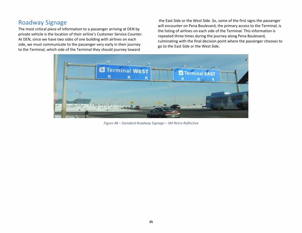
Roadway Signage The most critical piece of information to a passenger arriving at DEN by private vehicle is the location of their airline’s Customer Service Counter. At DEN, since we have two sides of one building with airlines on each side, we must communicate to the passenger very early in their journey to the Terminal, which side of the Terminal they should journey toward
the East Side or the West Side. So, some of the first signs the passenger will encounter on Pena Boulevard, the primary access to the Terminal, is the listing of airlines on each side of the Terminal. This information is repeated three times during the journey along Pena Boulevard, culminating with the final decision point where the passenger chooses to go to the East Side or the West Side.
Figure 48 – Standard Roadway Signage – 3M Retro-Reflective

26
Curbside Signage Each curbside on Levels 4, 5, and 6 on both the east and west sides of the Terminal have signs above the sidewalk indicating relative locations of airlines within the Terminal building. Level 6, the Departures Level, has curbside signs roughly corresponding to either the Airline Customer Service Counter on the interior of Level 6, or the airline’s curbside check-in location, if they have one. Level 5, the Ground Transportation Level, has curbside signs roughly corresponding to the location of either the airline’s assigned Baggage Carousel on the interior of Level 5 or the location of the Airline Customer Service Counter on Level 6 above. Level 4, the Arrivals Level (where the passenger can be picked up by a private vehicle by friends and family), has curbside signs roughly corresponding to the location of the airline’s assigned Baggage Carousel on Level 5 above. The availability of signage locations and the number of locations to be assigned to any one airline will be discussed and determined by the DEN Signage Program Manager and the DEN Airline Properties Office.
Figure 49 – Curbside Signage

27
Airline Customer Service Counter Backwall Signage The design intent of the Customer Service Counter Backwall is to provide a signband 40” tall, and centered vertically on the second reveal above the finished floor. This scenario serves as the model for approval by consent. If an Airline would like to propose a larger sign or any electronic sign solutions on their Customer Service Counter Backwall, they would be required to apply through their DEN PM for review of their proposal by the DEN PM (the liaison to the DRC) and/or the DRC.
Figure 50 – Backwall Signband – Standard Height
The Customer Service Counter Backwall is to remain painted with the current standard manufactured by Crafton Coatings. No painted graphics will be allowed on the Customer Service Counter Backwall. The Airline shall provide Customer Service Counter Backwall signs via applied signs and they shall be hung with concealed fasteners.
Whenever a signage program is revised requiring patch and repair of the gypsum board system on the Customer Service Counter Backwall, the DEN PM will negotiate with the Paint Shop of Airport Infrastructure Management – Facility Maintenance to undertake the patch and repair and the application of the proprietary paint that serves to identify the uniqueness of the Terminal. (Customer Service Counter Backwall Signs may be internally illuminated, but approval will depend on an accurate representation of the brightness and the nature of the illumination.)
Figure 51 – Backwall Signband – Standard Height
28
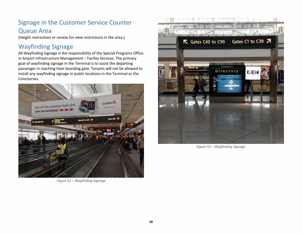
Signage in the Customer Service Counter Queue Area (Height restrictions or review for view restrictions in the area.)
Wayfinding Signage All Wayfinding Signage is the responsibility of the Special Programs Office in Airport Infrastructure Management – Facility Services. The primary goal of wayfinding signage in the Terminal is to assist the departing passenger in reaching their boarding gate. Tenants will not be allowed to install any wayfinding signage in public locations in the Terminal or the Concourses.
Figure 52 – Wayfinding Signage
Figure 53 – Wayfinding Signage

29
Gate Identification – Blade Signs Along the length of the Concourse, each boarding gate area is identified with a “blade sign” cantilevered from the structure separating the primary circulation space from the Holdroom area. The blade sign displays the boarding gate number, along with the Concourse on which it is located. For example, the boarding gate numbered 36 on Concourse B has its blade sign displaying “B36.” The gate numbering convention has all even-numbered gates located on the south side of each Concourse and all odd-numbered gates located on the north side of each Concourse.
Each blade sign is also equipped with an LED sign panel that is used to display the destination served by the next flight leaving from that Boarding Gate. The data feed for this destination information is supplied by the airline.
Figure 54 – Blade Sign

30
Gate Podium and Backwall Signage The original Backwall Signage design utilized LED arrays for flight identification and details. These signs are reaching the end of their useful life and are being systematically replaced by LCD Monitors.
Figure 55 – Gate Podium and Backwall Signage – LED
Figure 56 – Gate Podium and Backwall Signage – LCD

31
Passenger Loading Bridge Signage (exterior) Airlines will be permitted to install one airline logo/logotype sign on each side of each of their preferential boarding gates on the Concourses. Obviously, the exterior sign can only be attached to the portion of the bridge tube furthest from the building, the portion that retracts over the inner tube sections. The maximum size of the sign has been set at 5’ x 5’, which is the dimension from centerline of ribbed area to centerline of ribbed area plus the width of one rib (see illustration). (No airline identification signs will be allowed on the exterior of Passenger Loading Bridges serving common-use gates (i.e., non-preferential boarding gates).)
Figure 57 – Passenger Loading Bridge Signage (Exterior)
Passenger Loading Bridge Signage and Graphics (interior) Signage within the PLB can be unique to the preferential airline with approval from the DEN PM and with the understanding that the installation and condition of the graphic is the sole responsibility of the airline. Damage caused to the graphic by movement of the PLB will be the responsibility of the airline to repair. Damage caused to the graphic by scheduled or unscheduled maintenance of the PLB will be the responsibility of the airline to repair.
Outlying Building Signage Review by DEN PM, may require approval of the DEN no zoning requirements right now, DEN is its own “zone” with its own requirements.
Figure 58 – United Cargo

32
Joint-Use Cargo Building (JUC) This is a building that may house your cargo function. The exterior signage on this building will be limited to the sign band on the parapet. The limitations are that your sign can only be a maximum of 3’-0” tall, centered on the vertical dimension of the sign band. The width of the sign (or the length of the sign box) must fit between the roof drainage scuppers (approximately 20’-0” in width).
Figure 59 – Joint Use Cargo Building