Embed Size (px)
Citation preview

AirLinc 1.1 Reference RF Terminal and Serial Device Middleware Development Tool
Copyright © 1996 - 2005 by Connect, Inc.
All rights reserved. This document may not be reproduced in full or in part, in any form, without prior written permission of Connect Inc., 1701 Quincy Avenue, Suites 5 & 6, Naperville, IL 60540.
Connect, Inc. makes no representation or warranties with respect to the contents of this document and specifically disclaims any implied warranties of merchantability or fitness for any particular purpose. Further, Connect, Inc. reserves the right to revise this publication and to make changes to it from time to time without obligation to notify any person or organization of such revision or changes.
Trademarks
PowerNet Linux™, PowerNet Windows™, PowerNet 400™, PowerNet AirLinc™, PowerNet Twin Client™, and PowerNet OpenAir™ are trademarks of Connect, Inc.
Other product names mentioned in this manual may be trademarks or registered trademarks of their respective companies and are hereby acknowledged.
Production This manual was written, edited, and produced by:
Connect, Inc. 1701 Quincy Avenue, Suites 5 & 6 Naperville, IL 60540 www.connectrf.com
Printed in the U.S.A.
Please let us know about any errors in this document at: http://207.241.78.223/isoxpert/calltrak.nsf/WebTracking?OpenForm
Table of Contents
Chapter 1 • Introduction....................................................................................................... 1-1
PowerNet Products Overview.................................................................................................1-1 PowerNet AirLinc Overview ....................................................................................................1-1 Features……………………. ......................................................................................................1-2 In This Manual…………………… .............................................................................................1-2 Program Interface…………......................................................................................................1-3
Chapter 2 • System Installation and Terminal Configuration............................................ 2-1
Minimum Installation Requirements ......................................................................................2-1
Chapter 3 • System Operation ............................................................................................. 3-1
PowerNet AirLinc Standard System Menu Map ....................................................................3-1 Main Menu Bar……………........................................................................................................3-1 Project Manager Menu…………. .............................................................................................3-9
Chapter 4 • Building a Project ............................................................................................. 4-1
Overview…………………… ......................................................................................................4-1 Naming Your Project…….. ......................................................................................................4-3 Creating Users and Groups ....................................................................................................4-5 Creating Screens……………….. ..............................................................................................4-7 Building Scripts…………………. ...........................................................................................4-11
Chapter 5 • Testing Your Project......................................................................................... 5-1
Starting the AirLinc Simulator ................................................................................................5-1
Chapter 6 • Creating an ODBC Data Source....................................................................... 6-1
Establishing an ODBC-Compliant Data Source ....................................................................6-1 View Your Data Sources from AirLinc ...................................................................................6-3 Create a Copy of Your Working Database .............................................................................6-3
Chapter 7 • Creating Scripts ................................................................................................ 7-1
Building a New Script ..............................................................................................................7-1 Using AirLinc String Functions ............................................................................................7-11
Chapter 8 • Export / Import AirLinc Projects...................................................................... 8-1
Exporting an AirLinc Project...................................................................................................8-1 Importing an AirLinc Project...................................................................................................8-2
Chapter 9 • System Environment Variables, Terminators, and Special Functions....... 9-1
System Environment Variables ..............................................................................................9-1 Terminators………....................................................................................................................9-2 Special Functions.. ..................................................................................................................9-3
Chapter 1 • Introduction
PowerNet Products Overview PowerNet products bridge the gap between portable wireless devices and network applications, making the entire wireless enterprise as productive, efficient, and reliable as possible. The PowerNet family of products supports the following: • All Internet-compatible wireless networks, encompassing virtually all wireless LAN
technologies on the market today. Spectrum One, a proprietary spread spectrum wireless technology in the 900Mhz band, is also supported.
• All Internet-compatible wire network media, including Ethernet and Token Ring. • All major user interfaces, including HTML, VT/HP, 3270, and 5250. • All possible network application architectures including direct client, client-server,
and three-tier client server.
PowerNet consists of three major product families that work in unison to deliver a single, complete solution for the entire wireless enterprise. The focus of each of these products is described below. • PowerNet OpenAir: Hardware and middleware solutions for the wireless automatic
identification industry. This family includes the Linux-based PowerNet OpenAir Linux, Windows™-based PowerNet OpenAir Windows, the version of PowerNet Windows for the AS400 server, PowerNet OpenAir 400, and the universal terminal client software, PowerNet Twin Client.
• PowerNet DataLinc: Application development tools for RF, Serial, Digital, and Analog environment. The family currently includes PowerNet AirLinc.
PowerNet AirLinc Overview PowerNet AirLinc from Connect, Inc. is a “middleware” development tool for Radio Frequency (RF) Terminal and Serial Device based, data collection applications.
AirLinc is designed for installation in a Windows™ NT client /server environment. AirLinc Server may be installed on a Windows™ NT Server, Windows™ NT Workstation, or W2000 PC along with Connect's PowerNet OpenAir Windows. Together they provide RF connectivity for most 2.4Ghz and 900 MHz RF data collection terminals.
AirLinc Workstation may be installed on a Windows™ '95, '98, NT, 2000, or XP PC, and provides access to the AirLinc Server through a local or remote network connection.
PowerNet AirLinc 1.1 Reference • April, 2005 1-1
Introduction
AirLinc provides the RF data collection terminal interface you’ve needed for supplying information to your Accounting, Manufacturing, Warehousing, ERP, and MRP systems because AirLinc is the wireless link between your RF terminals and your existing data.
Features PowerNet AirLinc offers many features that allow you to quickly develop comprehensive data collection applications for RF terminals and serial communications devices. • Menu maintenance administration – You define RF terminal menus and user
permissions. Only those users given permission to use a menu item will have access to that menu item.
• No NVM downloading is required. – Unlike most application-generating software, AirLinc requires no NVM downloading. Instead AirLinc uses the existing PowerNet “thin” client interface from the PowerNet OpenAir Windows platform.
• ODBC compliant application scripting is an included feature. AirLinc uses ODBC compliant drivers (such as MS SQL Server, MS Access, MS FoxPro, Oracle, and Sybase) for data access. (Obtaining the correct ODBC driver is a customer responsibility.)
• No programming or compiling required – AirLinc’s fully interactive script builder allows you to choose from available database tables at table field level for viewing, updating, etc. The AirLinc Script Editor includes a command verb feature set of nearly 40 separate commands to allow you to create sophisticated terminal applications. Additional features include Boolean branching based on variable or static data, serial device control, SQL Transactional Commands, Stored Procedure Calls, and COM calls.
• Security administration with user name / password and activity logging – System administrators may create authorized users that have access to the appropriate menus that are user/group specific based on the need or security level. AirLinc provides diagnostic log files and the ability to capture more or less information.
• Error logging, debugging, and documentation tools are included.
In This Manual This manual is organized as follows: • Chapter 1 provides an overview of the PowerNet Product Line and an introduction to
PowerNet AirLinc. • Chapter 2 describes how to install PowerNet OpenAir Windows, AirLinc Server, and
AirLinc Workstation. Additionally, software Authorization and RF Terminal configuration details are described in this chapter.
• Chapter 3 defines the Main Menu Bar selections, with screen shots of the more prevalent topics.
• Chapter 4 gives summary information regarding the components of an AirLinc project then covers the steps required for creating an AirLinc project.
• Chapter 5 discusses the use of the AirLinc Simulator and methods for testing your projects.
1-2 PowerNet AirLinc 1.1 Reference • April, 2005
Program Interface
• Chapter 6 explains how to establish an ODBC data source name using the ODBC Administrator.
• Chapter 7 explains how to create AirLinc Scripts using the DataLinc Script Command Language.
• Chapter 8 discusses the Export and Import capability of AirLinc. • Chapter 9 presents System Environment Variables, Terminators, and special
Functions that may be used for capturing system information.
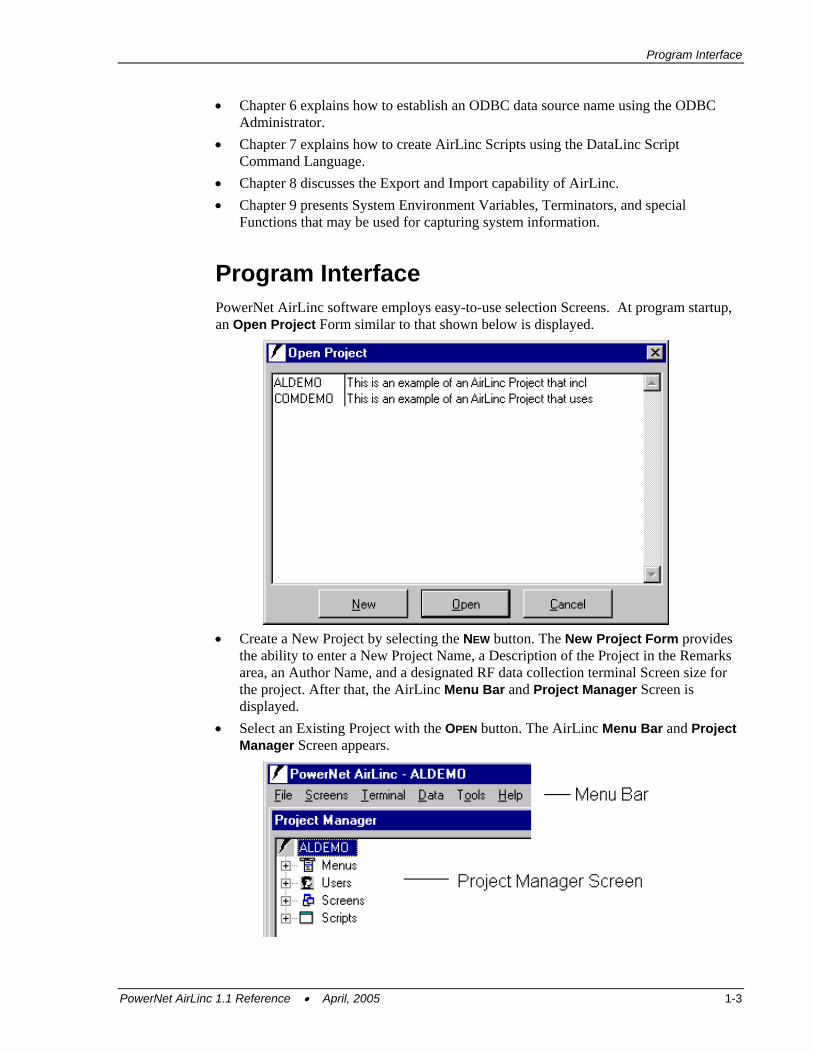
Program Interface PowerNet AirLinc software employs easy-to-use selection Screens. At program startup, an Open Project Form similar to that shown below is displayed.
• Create a New Project by selecting the NEW button. The New Project Form provides
the ability to enter a New Project Name, a Description of the Project in the Remarks area, an Author Name, and a designated RF data collection terminal Screen size for the project. After that, the AirLinc Menu Bar and Project Manager Screen is displayed.
• Select an Existing Project with the OPEN button. The AirLinc Menu Bar and Project Manager Screen appears.
PowerNet AirLinc 1.1 Reference • April, 2005 1-3
Introduction
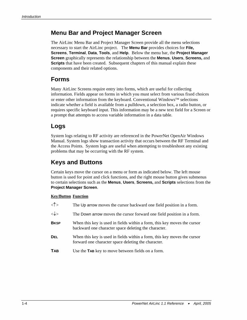
Menu Bar and Project Manager Screen The AirLinc Menu Bar and Project Manager Screen provide all the menu selections necessary to start the AirLinc project. The Menu Bar provides choices for File, Screens, Terminal, Data, Tools, and Help. Below the menu bar, the Project Manager Screen graphically represents the relationship between the Menus, Users, Screens, and Scripts that have been created. Subsequent chapters of this manual explain these components and their related options.
Forms Many AirLinc Screens require entry into forms, which are useful for collecting information. Fields appear on forms in which you must select from various fixed choices or enter other information from the keyboard. Conventional Windows™ selections indicate whether a field is available from a pulldown, a selection box, a radio button, or requires specific keyboard input. This information may be a new text field for a Screen or a prompt that attempts to access variable information in a data table.
Logs System logs relating to RF activity are referenced in the PowerNet OpenAir Windows Manual. System logs show transaction activity that occurs between the RF Terminal and the Access Points. System logs are useful when attempting to troubleshoot any existing problems that may be occurring with the RF system.
Keys and Buttons Certain keys move the cursor on a menu or form as indicated below. The left mouse button is used for point and click functions, and the right mouse button gives submenus to certain selections such as the Menus, Users, Screens, and Scripts selections from the Project Manager Screen. Key/Button Function
<↑> The Up arrow moves the cursor backward one field position in a form.
<↓> The Down arrow moves the cursor forward one field position in a form.
BKSP When this key is used in fields within a form, this key moves the cursor backward one character space deleting the character.
DEL When this key is used in fields within a form, this key moves the cursor forward one character space deleting the character.
TAB Use the TAB key to move between fields on a form.
1-4 PowerNet AirLinc 1.1 Reference • April, 2005
Chapter 2 • System Installation and Terminal Configuration
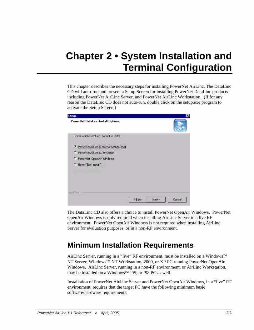
This chapter describes the necessary steps for installing PowerNet AirLinc. The DataLinc CD will auto-run and present a Setup Screen for installing PowerNet DataLinc products including PowerNet AirLinc Server, and PowerNet AirLinc Workstation. (If for any reason the DataLinc CD does not auto-run, double click on the setup.exe program to activate the Setup Screen.)
The DataLinc CD also offers a choice to install PowerNet OpenAir Windows. PowerNet OpenAir Windows is only required when installing AirLinc Server in a live RF environment. PowerNet OpenAir Windows is not required when installing AirLinc Server for evaluation purposes, or in a non-RF environment.
Minimum Installation Requirements AirLinc Server, running in a “live” RF environment, must be installed on a Windows™ NT Server, Windows™ NT Workstation, 2000, or XP PC running PowerNet OpenAir Windows. AirLinc Server, running in a non-RF environment, or AirLinc Workstation, may be installed on a Windows™ ’95, or ’98 PC as well.
Installation of PowerNet AirLinc Server and PowerNet OpenAir Windows, in a “live” RF environment, requires that the target PC have the following minimum basic software/hardware requirements:
PowerNet AirLinc 1.1 Reference • April, 2005 2-1
System Installation and Terminal Configuration
• Microsoft Windows™ NT Server or NT Workstation 4.0 with NT Service Pack 5.0 or later, or Microsoft Windows™ 2000.
• Internet Explorer 5.0 or later • Microsoft Internet Information Server or Peer Web Server • A Pentium III level processor with 128MB of RAM • 30 MB of available hard disk space
Note: Sizing of the installation platform is a function of how many terminals as well as how many applications are making a demand on resources.
Installation of PowerNet AirLinc Server, in a non-RF environment, or AirLinc Workstation, requires that the target PC have the following minimum basic software/hardware requirements: • Microsoft Windows™ ’95, ’98, NT Server, or NT Workstation 4.0 with NT Service
Pack 5.0 or later, Microsoft Windows™ 2000, or Microsoft Windows™ XP. • A Pentium III level processor with 64MB of RAM • 20 MB of free hard disk space available
Checking for Microsoft IIS or Peer Web Server PowerNet OpenAir Windows requires that Microsoft Internet Information Server (NT Server / W2000), or Microsoft Peer Web Server (NT Workstation) be running prior to installation. Both operate identically, but are named differently for the platforms. To check to see if the Internet Information Server (IIS), or the Peer Web Server program is enabled, use the following steps.
1. Click Start, Settings, Control Panel, and then select the Network icon.
2. Click the Services tab to see if the IIS or Peer Web Server is installed.
a. If IIS or Peer Web Server appears in this list, proceed to the next section entitled Installing PowerNet OpenAir Windows and AirLinc.
b. If IIS or Peer Web Server does not appear, install the service as follows:
3. Insert the Microsoft Windows™ NT Server CD in the CD ROM drive.
4. While on the Services tab of the Network Control Panel applet, click ADD. The system displays a list of available services.
5. Select the Internet Information Server (IIS) service to add. Consult the Microsoft Windows™ NT Server information manual for more information regarding the setup parameters for the IIS program.
Note: Some problems have been reported when attempting to install either of these Microsoft products. One solution is to delete the Registry Key W3SVC from your registry before attempting your installation. The W3SVC registry key is located in the HKEY_LOCAL_MACHINE / SYSTEM / CurrentControlSet / Services directory. EXTREME CAUTION must be used when working within your Registry. Before deleting the W3SVC Registry Key, we recommend that you perform a backup of your Registry by choosing Registry / Export Registry File and choosing ALL. This Registry File Export may be Imported back into the Registry if any problems arise.
6. Once IIS or Peer Web Server is installed, installation of PowerNet OpenAir Windows may proceed.
2-2 PowerNet AirLinc 1.1 Reference • April, 2005
Minimum Installation Requirements
Installing PowerNet OpenAir Windows and AirLinc 1. Place the PowerNet DataLinc CD into the CD-ROM drive of the PC. The DataLinc
CD will auto-run and present a selection screen for installing AirLinc Server, AirLinc Workstation, ControLinc, and PowerNet OpenAir Windows. (If for any reason the CD does not start the install process automatically, access your CD-ROM drive and run the Setup program from the DataLinc CD by double clicking on the Setup file icon.)
PowerNet OpenAir Windows Installation Note: Installation of PowerNet OpenAir Windows is required for real time RF Communications, but is not required for evaluating operation of AirLinc or ControLinc in a non-RF environment. AirLinc provides a RF Terminal Simulator Utility for development and testing that emulates operation of a RF Terminal. If this is a non-RF environment and you wish only to evaluate AirLinc proceed to the next section entitled PowerNet AirLinc Server Installation.
1. Choose the PowerNet OpenAir Windows option from the DataLinc CD selection screen. Follow all on-screen directions.
2. Click Next to proceed and choose the default target folder.
a) If you choose to change the default folder, click the BROWSE button and search for the folder you want to use.
3. Enter RF8800 when prompted for the CD Key.
4. Installation can be cancelled at any time by clicking on the CANCEL button to exit the installation process.
5. Select FINISH to complete the installation and reboot the system immediately.
6. If you wish to start the PowerNet OpenAir Windows software later, select the Restart Later option and then click on FINISH. This completes the PowerNet OpenAir Windows software installation process.
PowerNet AirLinc Server Installation 1. Return to the DataLinc CD software selection screen and choose PowerNet AirLinc
Server / Standalone. The AirLinc Server installation program will check for the existence of PowerNet OpenAir Windows, and offer a choice to Continue or Cancel if not found.
2. If AirLinc Server is being installed on a Windows™ ’95, or ’98 PC, or if PowerNet OpenAir Windows was not found, AirLinc Server will be installed as a standalone software program for evaluation purposes and step 4 below will not apply.
If AirLinc Server is being installed on a Windows™ NT Server, NT Workstation, 2000, or XP PC and PowerNet OpenAir Windows exists, AirLinc Server will be installed for full operation and the following steps apply.
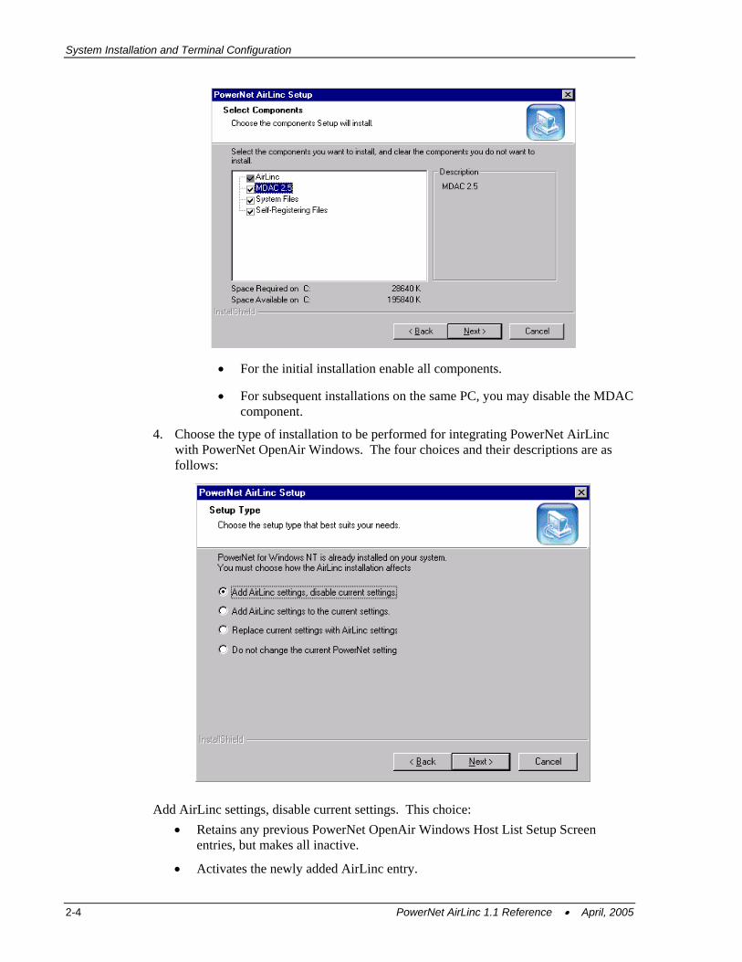
3. The AirLinc Server installation program will present choices for installing the necessary components to your PC.
PowerNet AirLinc 1.1 Reference • April, 2005 2-3
System Installation and Terminal Configuration
• For the initial installation enable all components.
• For subsequent installations on the same PC, you may disable the MDAC component.
4. Choose the type of installation to be performed for integrating PowerNet AirLinc with PowerNet OpenAir Windows. The four choices and their descriptions are as follows:
Add AirLinc settings, disable current settings. This choice: • Retains any previous PowerNet OpenAir Windows Host List Setup Screen
entries, but makes all inactive.
• Activates the newly added AirLinc entry.
2-4 PowerNet AirLinc 1.1 Reference • April, 2005
Minimum Installation Requirements
• When an RF terminal logs into the PowerNet OpenAir Windows, only AirLinc Host List is activated and you are prompted for AirLinc username and password.
Add AirLinc settings to the current settings. This choice: • Retains all previous settings in their current state.
• Adds AirLinc as an active Host List entry.
• When an RF terminal operator logs into the PowerNet OpenAir Windows, a list of available choices is presented, allowing you to choose AirLinc, or any other active Terminal Emulation or custom application host list entry previously available.
Replace current settings with AirLinc settings. This choice: • Eliminates all host list entries from the PowerNet OpenAir Windows Host List
Setup Screen, and only AirLinc will be available as an active entry.
• Activates the newly added AirLinc entry.
• When an RF terminal logs into PowerNet OpenAir Windows, only AirLinc Host List is activated and the user is prompted for AirLinc username and password.
Do not change the current PowerNet settings. This choice: • Retains all current settings within the PowerNet OpenAir Windows Setup Screen
and AirLinc is not automatically added.
• To activate AirLinc manually, the user must open the PowerNet OpenAir Windows Host List Setup Screen and add an entry similar to that which is discussed below in the Verification Section of this chapter.
3. Click Next. The PowerNet DataLinc CD continues with the installation of PowerNet AirLinc and makes any necessary changes to the Host List Setup Screen for PowerNet OpenAir Windows.
PowerNet AirLinc Workstation Installation
Note: AirLinc Workstation allows networked PC users to access executable files located on an AirLinc Server, for the purpose of developing AirLinc projects. PowerNet AirLinc Workstation should only be installed in an environment where PowerNet AirLinc Server already exists.
1. Return to the DataLinc CD software selection screen and choose PowerNet AirLinc Workstation.
2. Establish the same ODBC System DSNs on the AirLinc Workstation PC as are established on the AirLinc Server PC.
PowerNet AirLinc 1.1 Reference • April, 2005 2-5
System Installation and Terminal Configuration
Entering Your Authorization Code PowerNet OpenAir Windows uses an Authorization Code to permit use beyond the initial hour after installation. The Authorization Code controls the ability to run PowerNet AirLinc in a non-Demo mode and also controls the total number of RF terminals that may concurrently connect to the PowerNet OpenAir Windows in a RF environment. Authorization Codes are available through your reseller.
Your reseller will require a Machine ID before an Authorization Code can be generated. To obtain your Machine ID or enter your Authorization code use the following steps:
1. Start the AirLinc Server software.
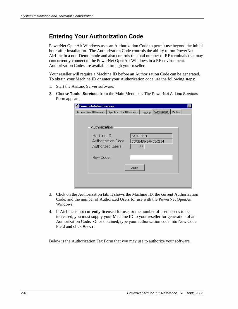
2. Choose Tools, Services from the Main Menu bar. The PowerNet AirLinc Services Form appears.
3. Click on the Authorization tab. It shows the Machine ID, the current Authorization
Code, and the number of Authorized Users for use with the PowerNet OpenAir Windows.
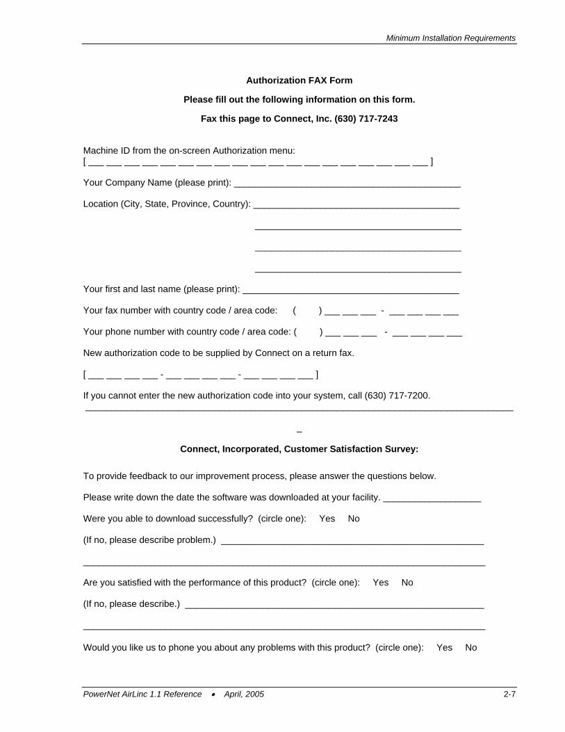
4. If AirLinc is not currently licensed for use, or the number of users needs to be increased, you must supply your Machine ID to your reseller for generation of an Authorization Code. Once obtained, type your authorization code into New Code Field and click APPLY.
Below is the Authorization Fax Form that you may use to authorize your software.
2-6 PowerNet AirLinc 1.1 Reference • April, 2005
Minimum Installation Requirements
Authorization FAX Form
Please fill out the following information on this form.
Fax this page to Connect, Inc. (630) 717-7243 Machine ID from the on-screen Authorization menu: [ ___ ___ ___ ___ ___ ___ ___ ___ ___ ___ ___ ___ ___ ___ ___ ___ ___ ___ ___ ] Your Company Name (please print): ____________________________________________ Location (City, State, Province, Country): ________________________________________
________________________________________
________________________________________
________________________________________
Your first and last name (please print): __________________________________________ Your fax number with country code / area code: ( ) ___ ___ ___ - ___ ___ ___ ___ Your phone number with country code / area code: ( ) ___ ___ ___ - ___ ___ ___ ___ New authorization code to be supplied by Connect on a return fax. [ ___ ___ ___ ___ - ___ ___ ___ ___ - ___ ___ ___ ___ ] If you cannot enter the new authorization code into your system, call (630) 717-7200. ___________________________________________________________________________________
_
Connect, Incorporated, Customer Satisfaction Survey:
To provide feedback to our improvement process, please answer the questions below. Please write down the date the software was downloaded at your facility. ___________________ Were you able to download successfully? (circle one): Yes No (If no, please describe problem.) ___________________________________________________ ______________________________________________________________________________ Are you satisfied with the performance of this product? (circle one): Yes No (If no, please describe.) __________________________________________________________ ______________________________________________________________________________ Would you like us to phone you about any problems with this product? (circle one): Yes No
PowerNet AirLinc 1.1 Reference • April, 2005 2-7
System Installation and Terminal Configuration
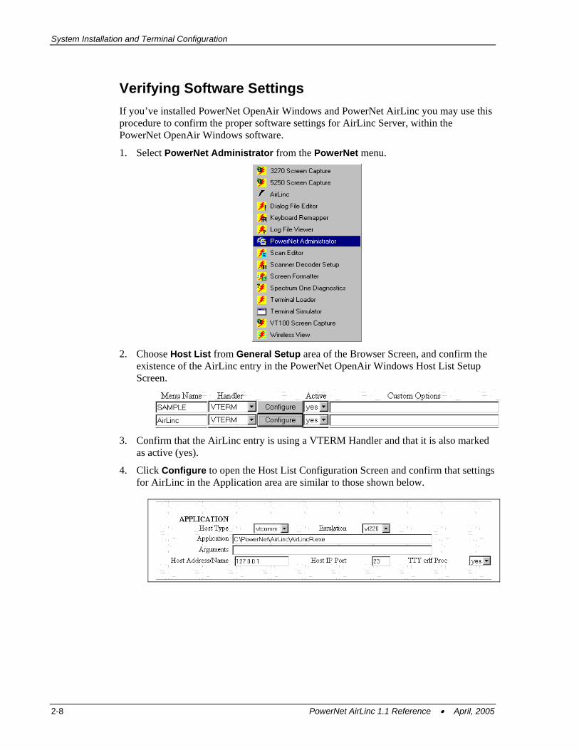
Verifying Software Settings If you’ve installed PowerNet OpenAir Windows and PowerNet AirLinc you may use this procedure to confirm the proper software settings for AirLinc Server, within the PowerNet OpenAir Windows software.
1. Select PowerNet Administrator from the PowerNet menu.
2. Choose Host List from General Setup area of the Browser Screen, and confirm the
existence of the AirLinc entry in the PowerNet OpenAir Windows Host List Setup Screen.
3. Confirm that the AirLinc entry is using a VTERM Handler and that it is also marked
as active (yes).
4. Click Configure to open the Host List Configuration Screen and confirm that settings for AirLinc in the Application area are similar to those shown below.
2-8 PowerNet AirLinc 1.1 Reference • April, 2005
Minimum Installation Requirements
Loading Terminal Software The RF data collection terminal must be loaded with the PowerNet Twin Client Terminal software for communications back to the AirLinc Server / PowerNet OpenAir Windows. PowerNet Twin Client terminal software is loaded using PowerNet Twin Client Manager.
The Connect, Inc. website located at www.connectrf.com has the Twin Client Manager available within the Software Downloads area of the Partner Services Page. Various types of RF Terminals exist. Choose the proper Twin Client Manager corresponding to your make of RF Terminal. The Twin Client Manager Manual is also available within the Partner Services Page or directly from OEM distributors.
Please refer to the Twin Client Manager Manual for directions on loading the Twin Client terminal software for your specific terminal. Configuring your RF Terminal and Establishing an AirLinc Session After the Twin Client terminal software has been transferred to the RF Terminal it will be necessary to configure the terminal for communications with the AirLinc Server. The Twin Client terminal software start screen will display “Any Key to Start”.
From the start screen, press the proper key sequence to produce an uppercase “C”. This action will present the configuration menu for the Twin Client terminal software.
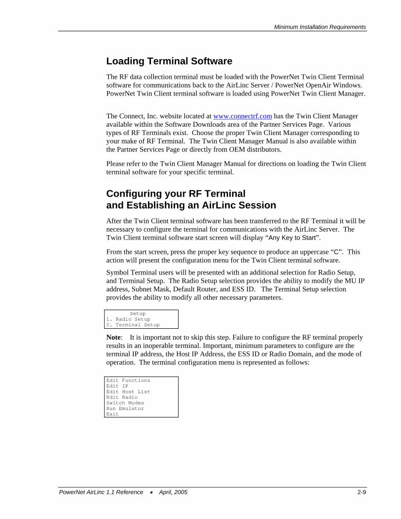
Symbol Terminal users will be presented with an additional selection for Radio Setup, and Terminal Setup. The Radio Setup selection provides the ability to modify the MU IP address, Subnet Mask, Default Router, and ESS ID. The Terminal Setup selection provides the ability to modify all other necessary parameters. Setup 1. Radio Setup 2. Terminal Setup
Note: It is important not to skip this step. Failure to configure the RF terminal properly results in an inoperable terminal. Important, minimum parameters to configure are the terminal IP address, the Host IP Address, the ESS ID or Radio Domain, and the mode of operation. The terminal configuration menu is represented as follows: Edit Functions Edit IP Edit Host List Edit Radio Switch Modes Run Emulator Exit
PowerNet AirLinc 1.1 Reference • April, 2005 2-9
System Installation and Terminal Configuration
Configuration Menu - Edit IP The Edit IP function allows you to set the Internet Protocol (IP) address of the RF device so that the terminal may attach to the TCP/IP network. As with any TCP/IP network, each device that attaches to the network must have an address associated with it. This function is used to set the address.
1. Choose the Edit IP selection by using the ARROW keys to highlight it. Press ENTER.
2. To set the terminal IP address, press the BACKSPACE key on the terminal to erase the current IP address displayed.
3. Enter the desired IP address for the terminal. Once the IP address is complete, press ENTER on the terminal and perform the same function for setting the sub-net mask.
4. If a router IP address is not required, enter 0.0.0.0 in the RT field, and press ENTER. Once the parameters are set, press F3 to save the changes and return to the configuration menu.
Note: Consult your site’s network manager to coordinate this IP address with other existing addresses on your network.
Configuration Menu – Edit Host List The host list function of the configuration menu allows you to set the IP address of the PowerNet Server PC.
1. Select the Edit Host List option and press ENTER.
2. Press the BACKSPACE key to clear the current entry field.
3. Enter the new IP address for the PowerNet OpenAir Windows.
4. Next, enter the Port number (1800 is the default when communicating to a PowerNet OpenAir Windows.)
Note: PowerNet OpenAir Windows allows entry of up to four host machines. This redundancy allows resiliency if a connection to one of the target servers should fail.
5. Once the values for these fields are set, press F3 to save the changes and return to the configuration menu.
Configuration Menu - Edit Radio Edit Radio allows changing the Radio Domain or Net ID of the terminal. The terminal’s Domain number or Net ID must match the Domain/Net ID listed in your Access Point’s radio configuration menu.
1. Choose the Edit Radio selection by using the ARROW keys to highlight it. Press ENTER. A Screen appears that lists the Domain/Net ID number.
2. Edit that number so it matches the Domain/Net ID of the Access Point’s radio configuration menu.
2-10 PowerNet AirLinc 1.1 Reference • April, 2005
Minimum Installation Requirements
Configuration Menu – Switch Modes By default, the Twin Client terminal software is setup to operate in “thick mode” or TN Client Based mode. In order to establish communications with the AirLinc Server it will be necessary to operate the terminal in “thin mode” or Server Based mode.
1. Cursor down to the Switch Modes selection and press ENTER.
2. An information screen is presented indicating that you have now switched to Server Based Mode. Press ENTER again to return to the Configuration Menu.
3. If the screen indicated that you are in TN Client Based Mode, repeat this operation until you are operating in Server Based Mode.
Configuration Menu – Run Emulation The Run Emulation function allows you to choose the type of terminal you are using.
1. Choose the Run Emulation selection by using the ARROW keys to highlight it. Press ENTER.
2. Choose the correct emulation for your terminal(s) and click OK.
Running PowerNet If modifications were made to either the IP address, or the Radio Domain/Net ID settings, it will be necessary to reboot the terminal to apply any changes.
1. Choose the Exit menu selection to exit the PowerNet Twin Client Terminal software and proceed with rebooting your terminal.
2. Consult your owner’s manual for instructions.
3. After rebooting the terminal, or choosing Run emulation from the menu, the Start Screen appears.
4. Press ENTER to start the session with the PowerNet OpenAir Windows system. AirLinc should be one of the host list entries presented.
• If multiple host entries are available, PowerNet OpenAir Windows displays a list of the host entries from which to choose.
• If there is only one target application host, PowerNet OpenAir Windows automatically connects to that host application.
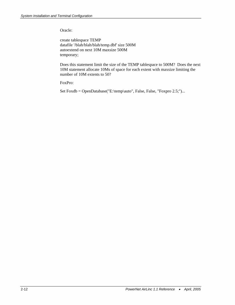
Note: A problem may arise when using Windows with AirLinc, depending on how the Windows server is built before PowerNet and AirLinc are installed. Should a problem arise, refer to the Windows error logs for information. In some cases, the Windows install specifies too small of an area for temp file storage, which impacts the number or kind of database files it can open and the number of RF devices that will connect. Refer also to the console messages, observed by minimizing all open windows on the desktop. To update the TEMP environment for your databases:
PowerNet AirLinc 1.1 Reference • April, 2005 2-11
System Installation and Terminal Configuration
Oracle:
create tablespace TEMP datafile '/blah/blah/blah/temp.dbf' size 500M autoextend on next 10M maxsize 500M temporary; Does this statement limit the size of the TEMP tablespace to 500M? Does the next 10M statement allocate 10Ms of space for each extent with maxsize limiting the number of 10M extents to 50?
FoxPro:
Set Foxdb = OpenDatabase("E:\temp\auto", False, False, "Foxpro 2.5;")...
2-12 PowerNet AirLinc 1.1 Reference • April, 2005
Chapter 3 • System Operation This System Operation Chapter explains the AirLinc Main Menu structure and the Project Manager Screen. Several utilities are included that provide information on Access Point, and Spectrum One RF operations, dynamic Log Level settings, Authorization Settings, and portable terminal printers.
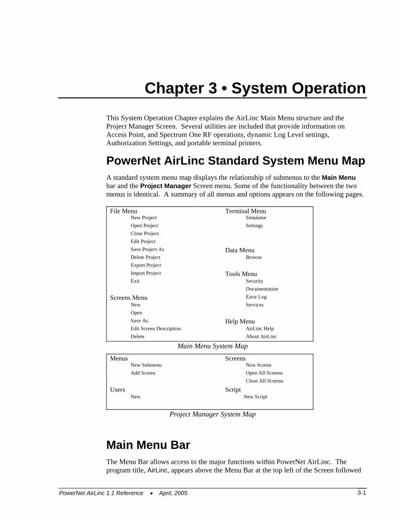
PowerNet AirLinc Standard System Menu Map A standard system menu map displays the relationship of submenus to the Main Menu bar and the Project Manager Screen menu. Some of the functionality between the two menus is identical. A summary of all menus and options appears on the following pages.
File Menu Terminal Menu New Project Simulator Open Project Settings Close Project Edit Project Save Project As Data Menu Delete Project Browse Export Project Import Project Tools Menu Exit Security
Documentation
Screens Menu Error Log New Services Open Save As Help Menu Edit Screen Description AirLinc Help Delete About AirLinc
Main Menu System Map
Menus Screens New Submenu New Screen Add Screen Open All Screens Close All Screens
Users Script New New Script
Project Manager System Map
Main Menu Bar The Menu Bar allows access to the major functions within PowerNet AirLinc. The program title, AirLinc, appears above the Menu Bar at the top left of the Screen followed
PowerNet AirLinc 1.1 Reference • April, 2005 3-1
System Operation
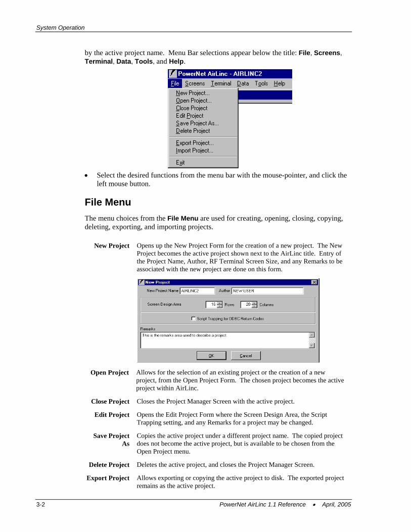
by the active project name. Menu Bar selections appear below the title: File, Screens, Terminal, Data, Tools, and Help.
• Select the desired functions from the menu bar with the mouse-pointer, and click the
left mouse button.
File Menu The menu choices from the File Menu are used for creating, opening, closing, copying, deleting, exporting, and importing projects.
New Project Opens up the New Project Form for the creation of a new project. The New Project becomes the active project shown next to the AirLinc title. Entry of the Project Name, Author, RF Terminal Screen Size, and any Remarks to be associated with the new project are done on this form.
Open Project Allows for the selection of an existing project or the creation of a new project, from the Open Project Form. The chosen project becomes the active project within AirLinc.
Close Project Closes the Project Manager Screen with the active project.
Edit Project Opens the Edit Project Form where the Screen Design Area, the Script Trapping setting, and any Remarks for a project may be changed.
Save Project As
Copies the active project under a different project name. The copied project does not become the active project, but is available to be chosen from the Open Project menu.
Delete Project Deletes the active project, and closes the Project Manager Screen.
Export Project Allows exporting or copying the active project to disk. The exported project remains as the active project.
3-2 PowerNet AirLinc 1.1 Reference • April, 2005
Main Menu Bar
Import Project Allows importing or copying an existing AirLinc project (*.air) from disk. The imported project does not become the active project, but is available for selection from the Open Project Form. Additionally, imported projects do not retain previously assigned users from the original project.
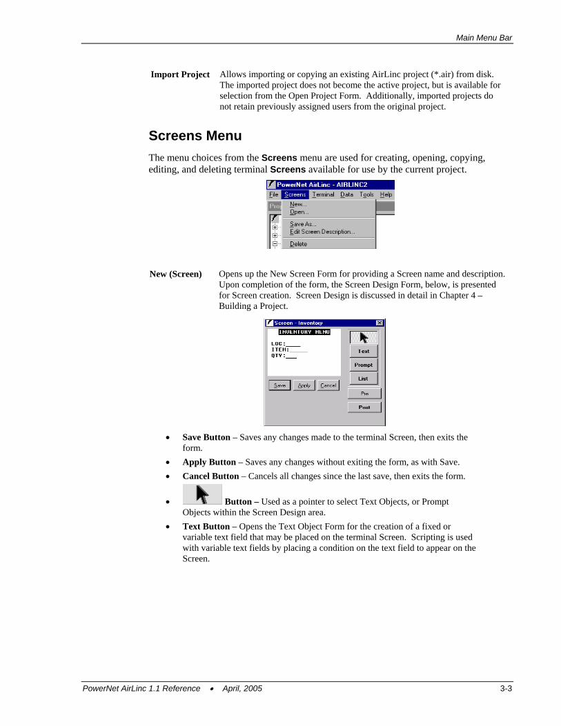
Screens Menu The menu choices from the Screens menu are used for creating, opening, copying, editing, and deleting terminal Screens available for use by the current project.
New (Screen) Opens up the New Screen Form for providing a Screen name and description. Upon completion of the form, the Screen Design Form, below, is presented for Screen creation. Screen Design is discussed in detail in Chapter 4 – Building a Project.
• Save Button – Saves any changes made to the terminal Screen, then exits the
form. • Apply Button – Saves any changes without exiting the form, as with Save. • Cancel Button – Cancels all changes since the last save, then exits the form.
• Button – Used as a pointer to select Text Objects, or Prompt Objects within the Screen Design area.
• Text Button – Opens the Text Object Form for the creation of a fixed or variable text field that may be placed on the terminal Screen. Scripting is used with variable text fields by placing a condition on the text field to appear on the Screen.
PowerNet AirLinc 1.1 Reference • April, 2005 3-3
System Operation
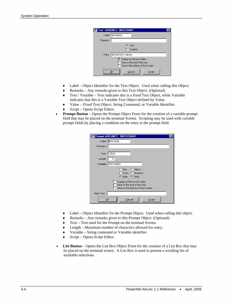
♦ Label – Object Identifier for the Text Object. Used when calling this Object. ♦ Remarks – Any remarks given to this Text Object. (Optional) ♦ Text / Variable – Text indicates this is a fixed Text Object, while Variable
indicates that this is a Variable Text Object defined by Value. ♦ Value – Fixed Text Object, String Command, or Variable Identifier. ♦ Script – Opens Script Editor.
• Prompt Button – Opens the Prompt Object Form for the creation of a variable prompt field that may be placed on the terminal Screen. Scripting may be used with variable prompt fields by placing a condition on the entry to the prompt field.
♦ Label – Object Identifier for the Prompt Object. Used when calling this object. ♦ Remarks – Any remarks given to this Prompt Object. (Optional) ♦ Text – Text used for the Prompt on the terminal Screen. ♦ Length – Maximum number of characters allowed for entry. ♦ Variable – String command or Variable identifier. ♦ Script – Opens Script Editor.
• List Button – Opens the List Box Object Form for the creation of a List Box that may
be placed on the terminal screen. A List Box is used to present a scrolling list of available selections.
3-4 PowerNet AirLinc 1.1 Reference • April, 2005
Main Menu Bar
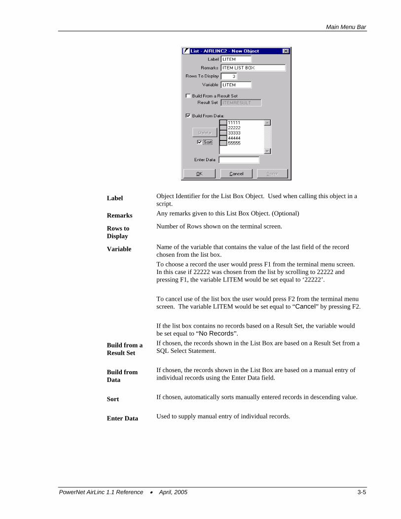
Label Object Identifier for the List Box Object. Used when calling this object in a script.
Remarks Any remarks given to this List Box Object. (Optional)
Rows to Display
Number of Rows shown on the terminal screen.
Variable Name of the variable that contains the value of the last field of the record chosen from the list box. To choose a record the user would press F1 from the terminal menu screen. In this case if 22222 was chosen from the list by scrolling to 22222 and pressing F1, the variable LITEM would be set equal to ‘22222’. To cancel use of the list box the user would press F2 from the terminal menu screen. The variable LITEM would be set equal to “Cancel” by pressing F2. If the list box contains no records based on a Result Set, the variable would be set equal to “No Records”.
Build from a Result Set
If chosen, the records shown in the List Box are based on a Result Set from a SQL Select Statement.
Build from Data
If chosen, the records shown in the List Box are based on a manual entry of individual records using the Enter Data field.
Sort If chosen, automatically sorts manually entered records in descending value.
Enter Data Used to supply manual entry of individual records.
PowerNet AirLinc 1.1 Reference • April, 2005 3-5
System Operation
• Pre Button – Allows for the creation of an AirLinc Script that is initiated upon Screen activation within an AirLinc application.
• Post Button – Allows for the creation of an AirLinc Script that is processed upon termination of a screen. Scripts contained within the Post processing area are often called from various scripts assigned to Text Objects or Prompt Objects.
Open Allows for the selection of an existing Screen from a list of available Screens.
Save As Opens the Save As Screen and copies the current Screen under a different name. The copied Screen does not become the active Screen, but is available to be chosen from the Open Screens menu.
Edit Screen Description
Allows for the editing of the description for the current Screen.
Delete Deletes the current open Screen. Verification is required to complete the deletion.
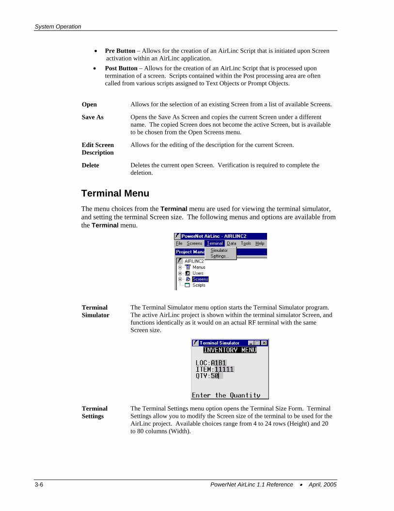
Terminal Menu The menu choices from the Terminal menu are used for viewing the terminal simulator, and setting the terminal Screen size. The following menus and options are available from the Terminal menu.
Terminal Simulator
The Terminal Simulator menu option starts the Terminal Simulator program. The active AirLinc project is shown within the terminal simulator Screen, and functions identically as it would on an actual RF terminal with the same Screen size.
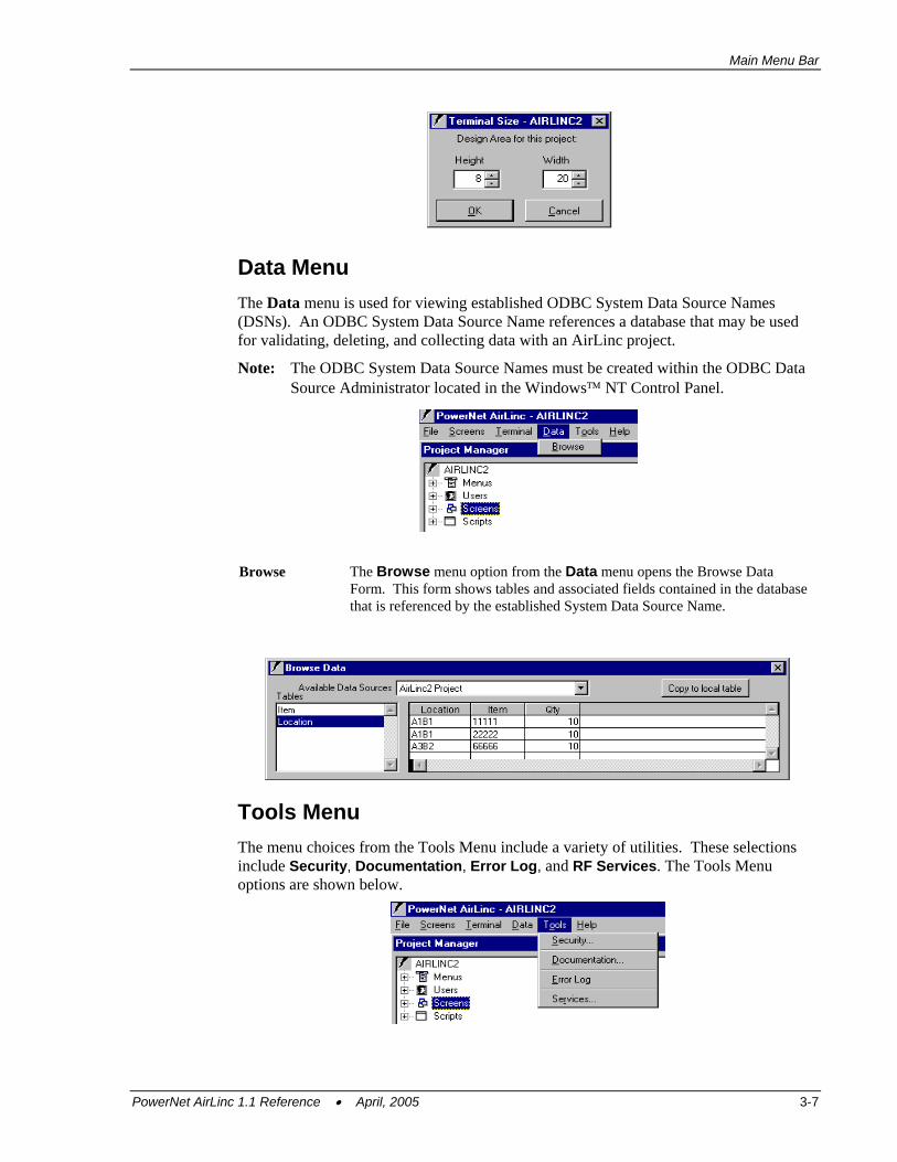
Terminal Settings
The Terminal Settings menu option opens the Terminal Size Form. Terminal Settings allow you to modify the Screen size of the terminal to be used for the AirLinc project. Available choices range from 4 to 24 rows (Height) and 20 to 80 columns (Width).
3-6 PowerNet AirLinc 1.1 Reference • April, 2005
Main Menu Bar
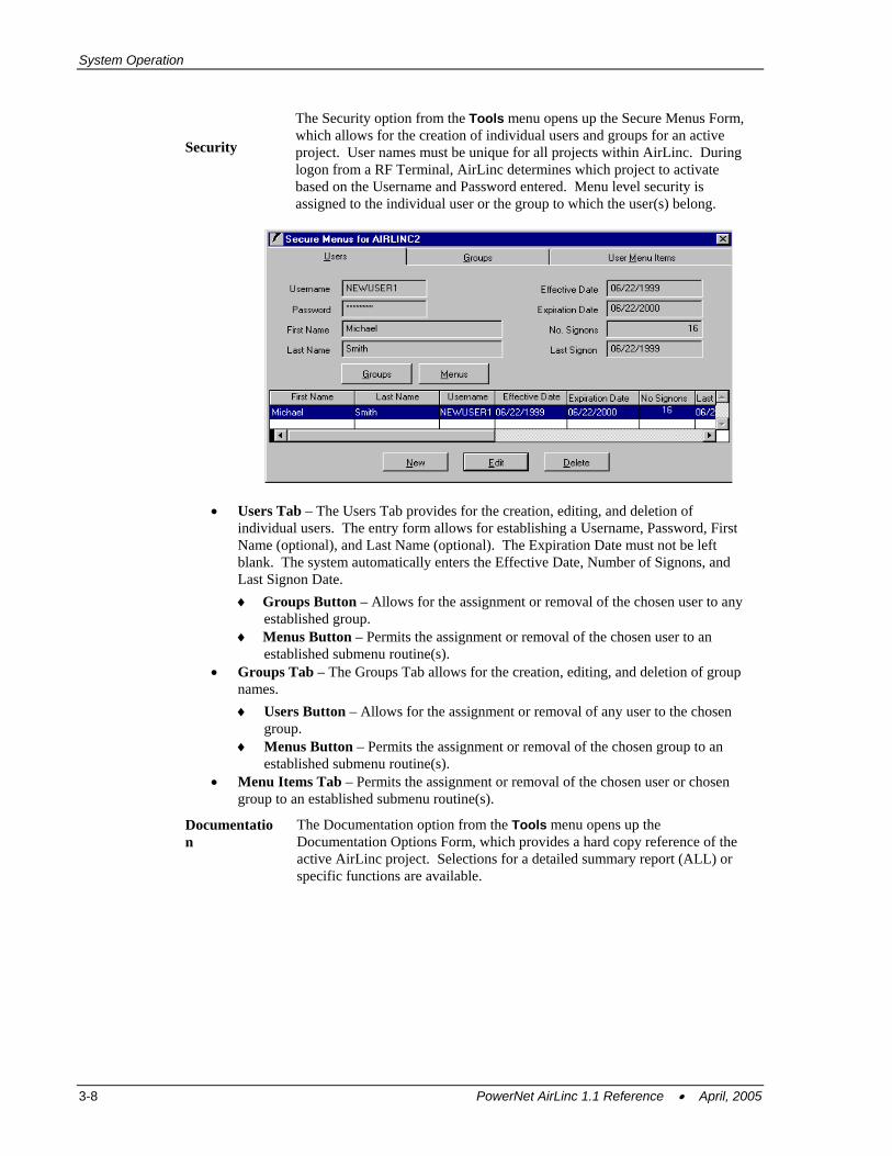
Data Menu The Data menu is used for viewing established ODBC System Data Source Names (DSNs). An ODBC System Data Source Name references a database that may be used for validating, deleting, and collecting data with an AirLinc project.
Note: The ODBC System Data Source Names must be created within the ODBC Data Source Administrator located in the Windows™ NT Control Panel.
Browse The Browse menu option from the Data menu opens the Browse Data Form. This form shows tables and associated fields contained in the database that is referenced by the established System Data Source Name.
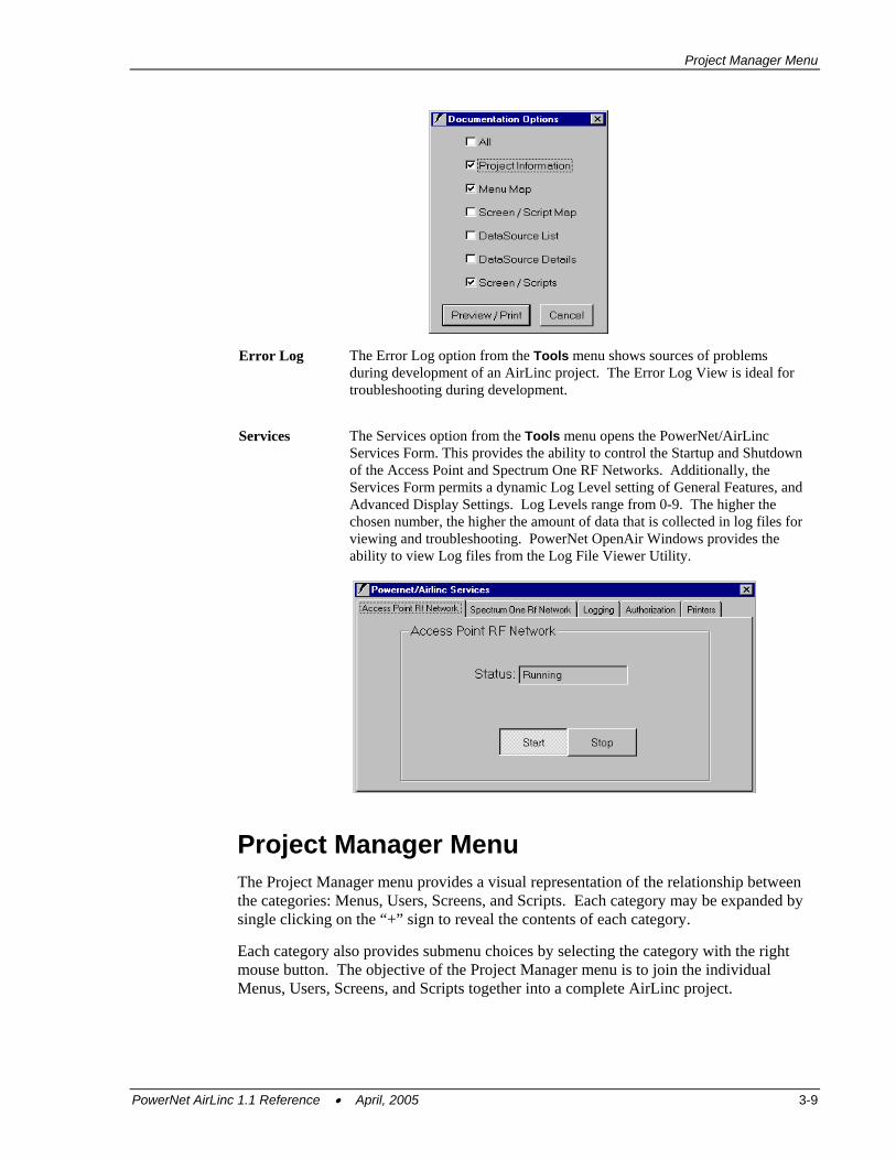
Tools Menu The menu choices from the Tools Menu include a variety of utilities. These selections include Security, Documentation, Error Log, and RF Services. The Tools Menu options are shown below.
PowerNet AirLinc 1.1 Reference • April, 2005 3-7
System Operation
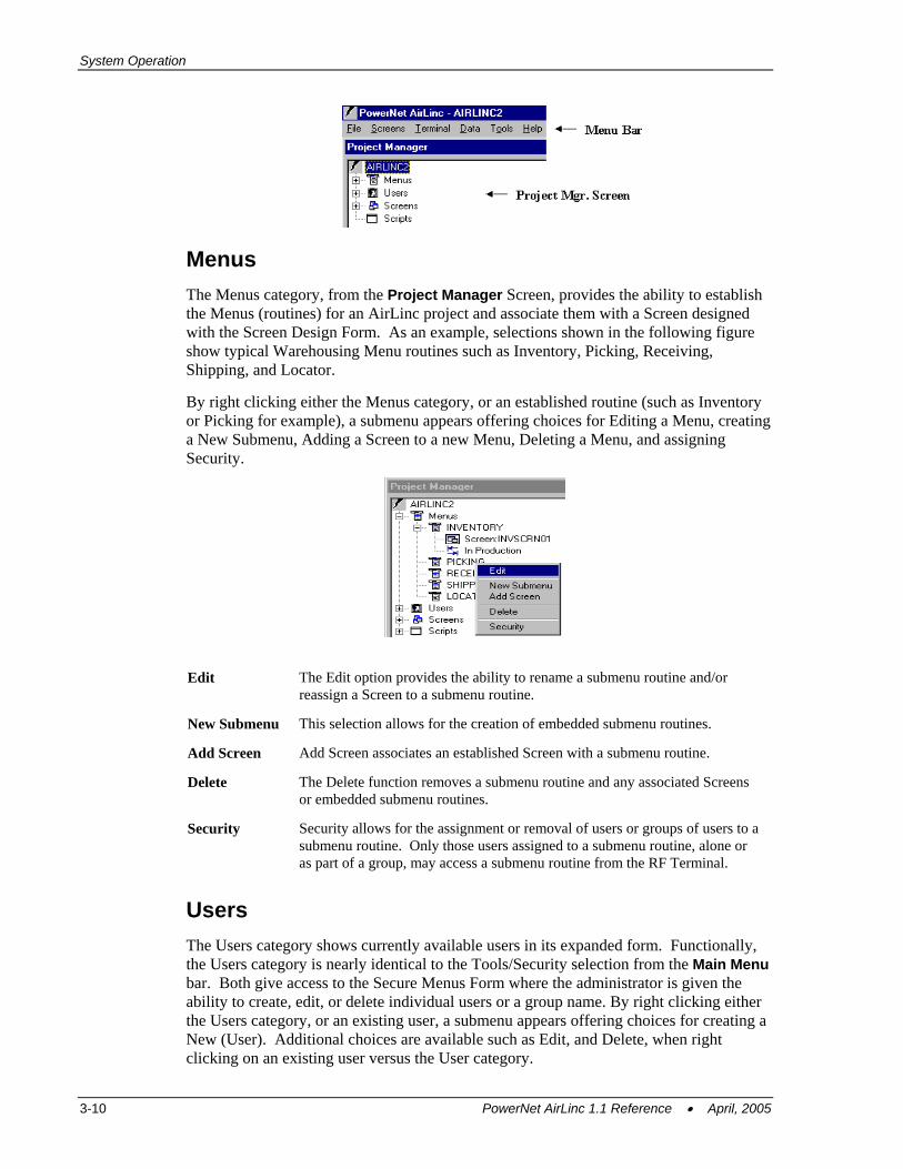
Security
The Security option from the Tools menu opens up the Secure Menus Form, which allows for the creation of individual users and groups for an active project. User names must be unique for all projects within AirLinc. During logon from a RF Terminal, AirLinc determines which project to activate based on the Username and Password entered. Menu level security is assigned to the individual user or the group to which the user(s) belong.
• Users Tab – The Users Tab provides for the creation, editing, and deletion of individual users. The entry form allows for establishing a Username, Password, First Name (optional), and Last Name (optional). The Expiration Date must not be left blank. The system automatically enters the Effective Date, Number of Signons, and Last Signon Date. ♦ Groups Button – Allows for the assignment or removal of the chosen user to any
established group. ♦ Menus Button – Permits the assignment or removal of the chosen user to an
established submenu routine(s). • Groups Tab – The Groups Tab allows for the creation, editing, and deletion of group
names. ♦ Users Button – Allows for the assignment or removal of any user to the chosen
group. ♦ Menus Button – Permits the assignment or removal of the chosen group to an
established submenu routine(s). • Menu Items Tab – Permits the assignment or removal of the chosen user or chosen
group to an established submenu routine(s).
Documentation
The Documentation option from the Tools menu opens up the Documentation Options Form, which provides a hard copy reference of the active AirLinc project. Selections for a detailed summary report (ALL) or specific functions are available.
3-8 PowerNet AirLinc 1.1 Reference • April, 2005
Project Manager Menu
Error Log The Error Log option from the Tools menu shows sources of problems during development of an AirLinc project. The Error Log View is ideal for troubleshooting during development.
Services The Services option from the Tools menu opens the PowerNet/AirLinc
Services Form. This provides the ability to control the Startup and Shutdown of the Access Point and Spectrum One RF Networks. Additionally, the Services Form permits a dynamic Log Level setting of General Features, and Advanced Display Settings. Log Levels range from 0-9. The higher the chosen number, the higher the amount of data that is collected in log files for viewing and troubleshooting. PowerNet OpenAir Windows provides the ability to view Log files from the Log File Viewer Utility.
Project Manager Menu The Project Manager menu provides a visual representation of the relationship between the categories: Menus, Users, Screens, and Scripts. Each category may be expanded by single clicking on the “+” sign to reveal the contents of each category.
Each category also provides submenu choices by selecting the category with the right mouse button. The objective of the Project Manager menu is to join the individual Menus, Users, Screens, and Scripts together into a complete AirLinc project.
PowerNet AirLinc 1.1 Reference • April, 2005 3-9
System Operation
Menus The Menus category, from the Project Manager Screen, provides the ability to establish the Menus (routines) for an AirLinc project and associate them with a Screen designed with the Screen Design Form. As an example, selections shown in the following figure show typical Warehousing Menu routines such as Inventory, Picking, Receiving, Shipping, and Locator.
By right clicking either the Menus category, or an established routine (such as Inventory or Picking for example), a submenu appears offering choices for Editing a Menu, creating a New Submenu, Adding a Screen to a new Menu, Deleting a Menu, and assigning Security.
Edit The Edit option provides the ability to rename a submenu routine and/or reassign a Screen to a submenu routine.
New Submenu This selection allows for the creation of embedded submenu routines.
Add Screen Add Screen associates an established Screen with a submenu routine.
Delete The Delete function removes a submenu routine and any associated Screens or embedded submenu routines.
Security Security allows for the assignment or removal of users or groups of users to a submenu routine. Only those users assigned to a submenu routine, alone or as part of a group, may access a submenu routine from the RF Terminal.
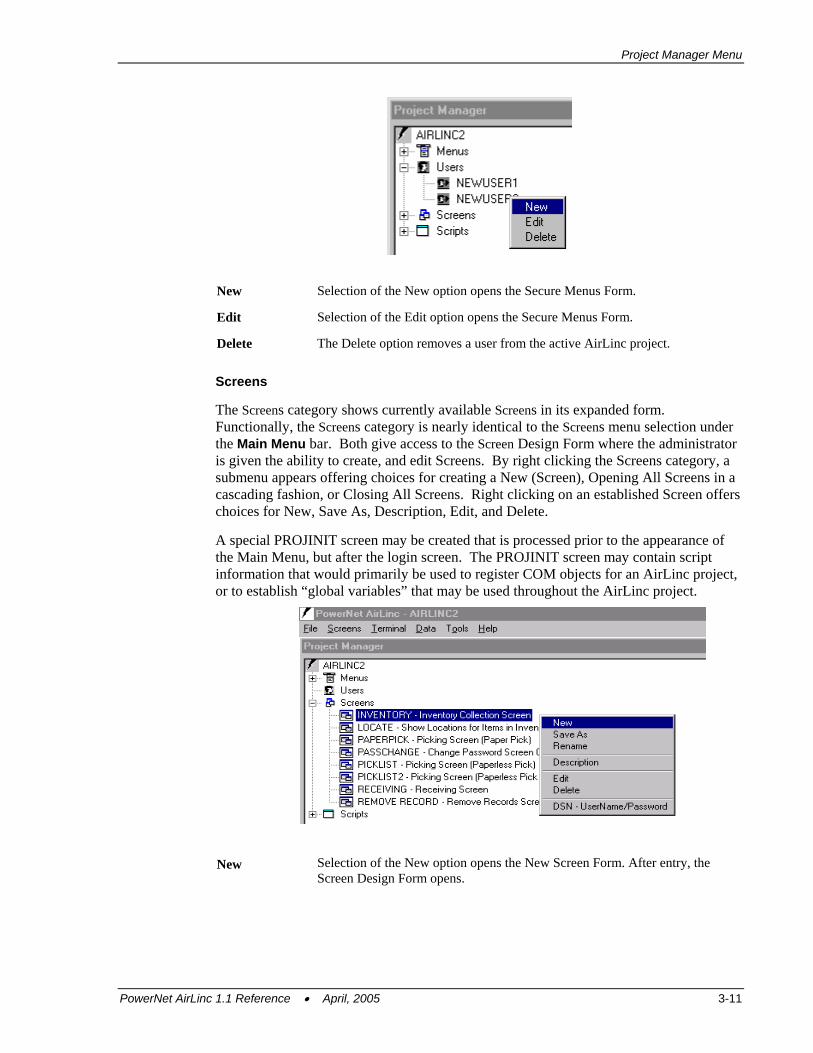
Users The Users category shows currently available users in its expanded form. Functionally, the Users category is nearly identical to the Tools/Security selection from the Main Menu bar. Both give access to the Secure Menus Form where the administrator is given the ability to create, edit, or delete individual users or a group name. By right clicking either the Users category, or an existing user, a submenu appears offering choices for creating a New (User). Additional choices are available such as Edit, and Delete, when right clicking on an existing user versus the User category.
3-10 PowerNet AirLinc 1.1 Reference • April, 2005
Project Manager Menu
New Selection of the New option opens the Secure Menus Form.
Edit Selection of the Edit option opens the Secure Menus Form.
Delete The Delete option removes a user from the active AirLinc project.
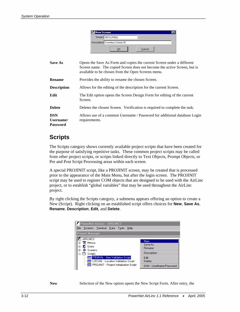
Screens The Screens category shows currently available Screens in its expanded form. Functionally, the Screens category is nearly identical to the Screens menu selection under the Main Menu bar. Both give access to the Screen Design Form where the administrator is given the ability to create, and edit Screens. By right clicking the Screens category, a submenu appears offering choices for creating a New (Screen), Opening All Screens in a cascading fashion, or Closing All Screens. Right clicking on an established Screen offers choices for New, Save As, Description, Edit, and Delete.
A special PROJINIT screen may be created that is processed prior to the appearance of the Main Menu, but after the login screen. The PROJINIT screen may contain script information that would primarily be used to register COM objects for an AirLinc project, or to establish “global variables” that may be used throughout the AirLinc project.
New
Selection of the New option opens the New Screen Form. After entry, the Screen Design Form opens.
PowerNet AirLinc 1.1 Reference • April, 2005 3-11
System Operation
Save As Opens the Save As Form and copies the current Screen under a different Screen name. The copied Screen does not become the active Screen, but is available to be chosen from the Open Screens menu.
Rename Provides the ability to rename the chosen Screen.
Description Allows for the editing of the description for the current Screen.
Edit The Edit option opens the Screen Design Form for editing of the current Screen.
Delete Deletes the chosen Screen. Verification is required to complete the task.
DSN Username/ Password
Allows use of a common Username / Password for additional database Login requirements.
Scripts The Scripts category shows currently available project scripts that have been created for the purpose of satisfying repetitive tasks. These common project scripts may be called from other project scripts, or scripts linked directly to Text Objects, Prompt Objects, or Pre and Post Script Processing areas within each screen.
A special PROJINIT script, like a PROJINIT screen, may be created that is processed prior to the appearance of the Main Menu, but after the login screen. The PROJINIT script may be used to register COM objects that are designed to be used with the AirLinc project, or to establish “global variables” that may be used throughout the AirLinc project.
By right clicking the Scripts category, a submenu appears offering an option to create a New (Script). Right clicking on an established script offers choices for New, Save As, Rename, Description, Edit, and Delete.
New Selection of the New option opens the New Script Form. After entry, the
3-12 PowerNet AirLinc 1.1 Reference • April, 2005
Project Manager Menu
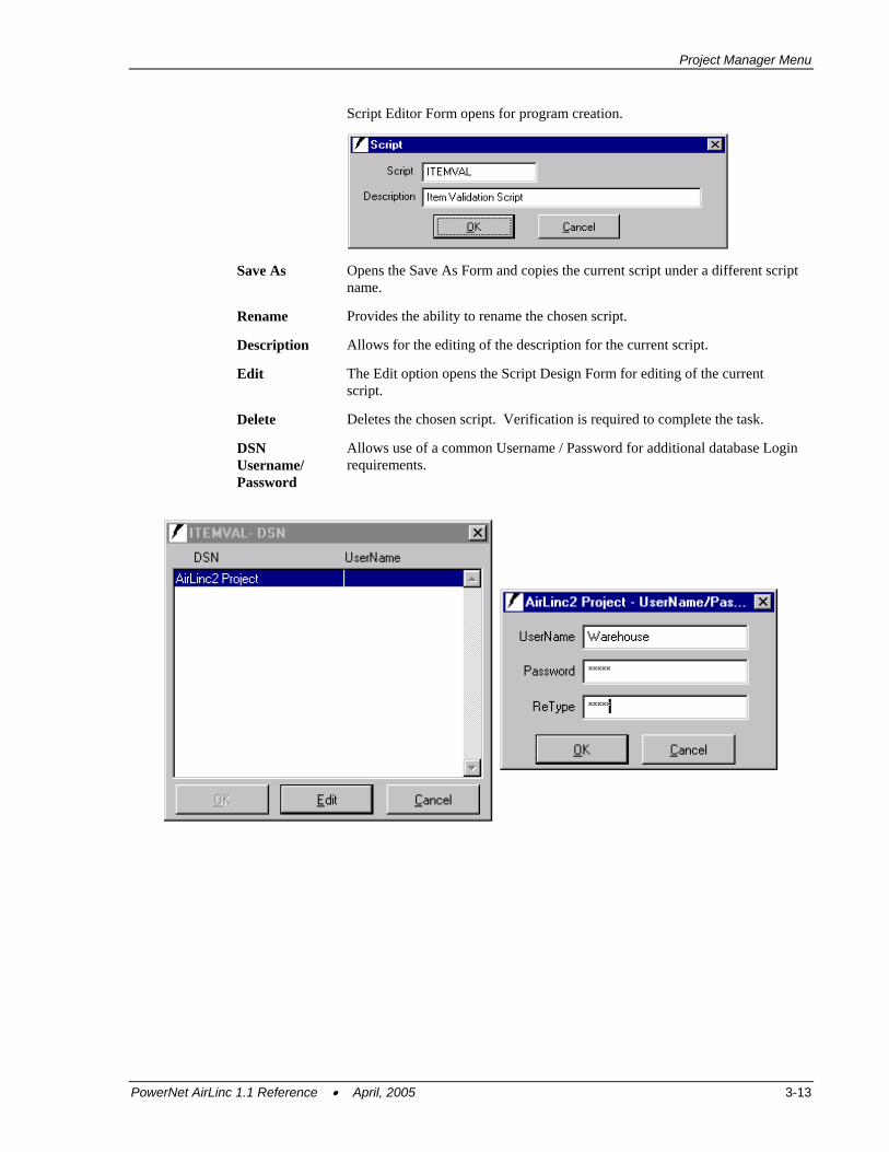
Script Editor Form opens for program creation.
Save As Opens the Save As Form and copies the current script under a different script name.
Rename Provides the ability to rename the chosen script.
Description Allows for the editing of the description for the current script.
Edit The Edit option opens the Script Design Form for editing of the current script.
Delete Deletes the chosen script. Verification is required to complete the task.
DSN Username/ Password
Allows use of a common Username / Password for additional database Login requirements.
PowerNet AirLinc 1.1 Reference • April, 2005 3-13

System Operation
This page is intentionally blank.
3-14 PowerNet AirLinc 1.1 Reference • April, 2005
Chapter 4 • Building a Project This chapter gives an overview of the components and steps required for building an AirLinc project, as well as a tutorial for creating your own AirLinc project.
Overview An AirLinc project consists of: • Naming your Project • Creating Menus and Routines • Establishing Users and Groups • Building Screens and Scripts • Testing your Project
Naming Your Project - The first step in creating an AirLinc project is to name it, and to designate the screen size of the RF terminal. Optional text may be added that describes your AirLinc project to future users.
Creating Menus – Next you’ll want to create a menu. A menu is a list of data collection routines that appear on a RF Terminal Screen. Routines are typically named for their function, for example, Inventory, Shipping, or Receiving.
Once a menu is defined, a User or Group of users must be created that are authorized for access to each routine within that menu.
Creating Users and Groups - Users and Groups are established to limit access to menu routines. AirLinc projects require Users to log in when accessing the AirLinc Server. The unique Username / Password entered on the RF Terminal dictates the AirLinc project to be used and the level of access available through User and Group security.
Creating Screens – RF Terminal Screens need to be created by using the AirLinc Screen Design Form. Screens can then be associated with Menu routines. Screens may contain Text objects, Prompt objects, List Boxes, and Scripts. Screens may be viewed using the AirLinc Simulator and appear identically as actual RF Terminal Screens.
Creating Scripts - Scripts can be added that give the AirLinc Project its’ flow. Scripts are a collection of commands that accomplish a specific, work-related task. For example, a script can display text information, prompt the user for additional information, update databases, call screens, or even other scripts. Scripts in AirLinc exist at four levels: • An optional Project initialization Script, that must be named “Projinit”, may be
created that is executed after login, but prior to any Menu routine selection. The primary purpose of the Projinit Script is to establish global variables for an AirLinc Project, and to initialize any COM objects to be used with your AirLinc Project.
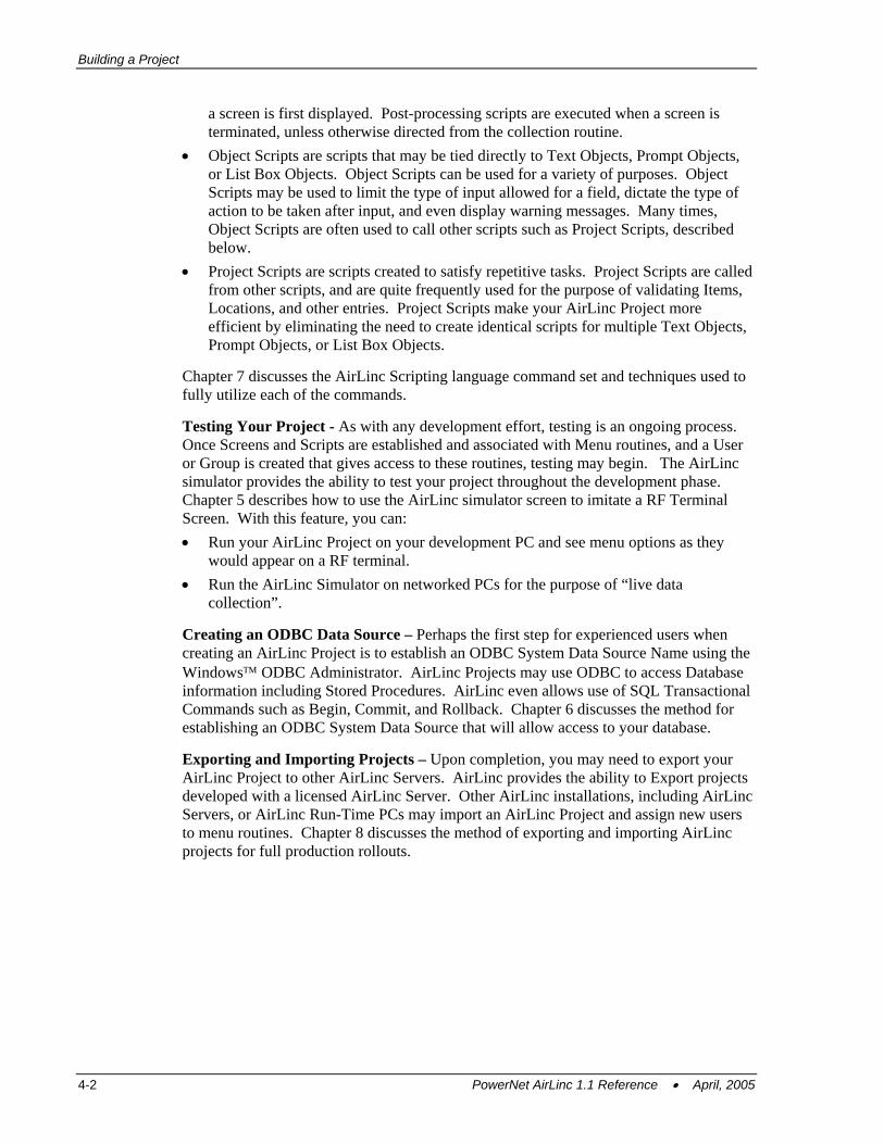
• Screen Scripts are specific to a screen and can exist in the Pre-processing area of the screen, as well as the Post-processing area. Pre-processing scripts are executed when
PowerNet AirLinc 1.1 Reference • April, 2005 4-1
Building a Project
a screen is first displayed. Post-processing scripts are executed when a screen is terminated, unless otherwise directed from the collection routine.
• Object Scripts are scripts that may be tied directly to Text Objects, Prompt Objects, or List Box Objects. Object Scripts can be used for a variety of purposes. Object Scripts may be used to limit the type of input allowed for a field, dictate the type of action to be taken after input, and even display warning messages. Many times, Object Scripts are often used to call other scripts such as Project Scripts, described below.
• Project Scripts are scripts created to satisfy repetitive tasks. Project Scripts are called from other scripts, and are quite frequently used for the purpose of validating Items, Locations, and other entries. Project Scripts make your AirLinc Project more efficient by eliminating the need to create identical scripts for multiple Text Objects, Prompt Objects, or List Box Objects.
Chapter 7 discusses the AirLinc Scripting language command set and techniques used to fully utilize each of the commands.
Testing Your Project - As with any development effort, testing is an ongoing process. Once Screens and Scripts are established and associated with Menu routines, and a User or Group is created that gives access to these routines, testing may begin. The AirLinc simulator provides the ability to test your project throughout the development phase. Chapter 5 describes how to use the AirLinc simulator screen to imitate a RF Terminal Screen. With this feature, you can: • Run your AirLinc Project on your development PC and see menu options as they
would appear on a RF terminal. • Run the AirLinc Simulator on networked PCs for the purpose of “live data
collection”.
Creating an ODBC Data Source – Perhaps the first step for experienced users when creating an AirLinc Project is to establish an ODBC System Data Source Name using the Windows™ ODBC Administrator. AirLinc Projects may use ODBC to access Database information including Stored Procedures. AirLinc even allows use of SQL Transactional Commands such as Begin, Commit, and Rollback. Chapter 6 discusses the method for establishing an ODBC System Data Source that will allow access to your database.
Exporting and Importing Projects – Upon completion, you may need to export your AirLinc Project to other AirLinc Servers. AirLinc provides the ability to Export projects developed with a licensed AirLinc Server. Other AirLinc installations, including AirLinc Servers, or AirLinc Run-Time PCs may import an AirLinc Project and assign new users to menu routines. Chapter 8 discusses the method of exporting and importing AirLinc projects for full production rollouts.
4-2 PowerNet AirLinc 1.1 Reference • April, 2005
Naming Your Project
Naming Your Project Newly created menu routines appear under the Menus Category in the AirLinc Project Manager Screen on your development PC. Later, these same menu routines will appear on a RF Terminal Screen as selections for different activities that may be performed (i.e. Inventory, Picking, Receiving, etc.)
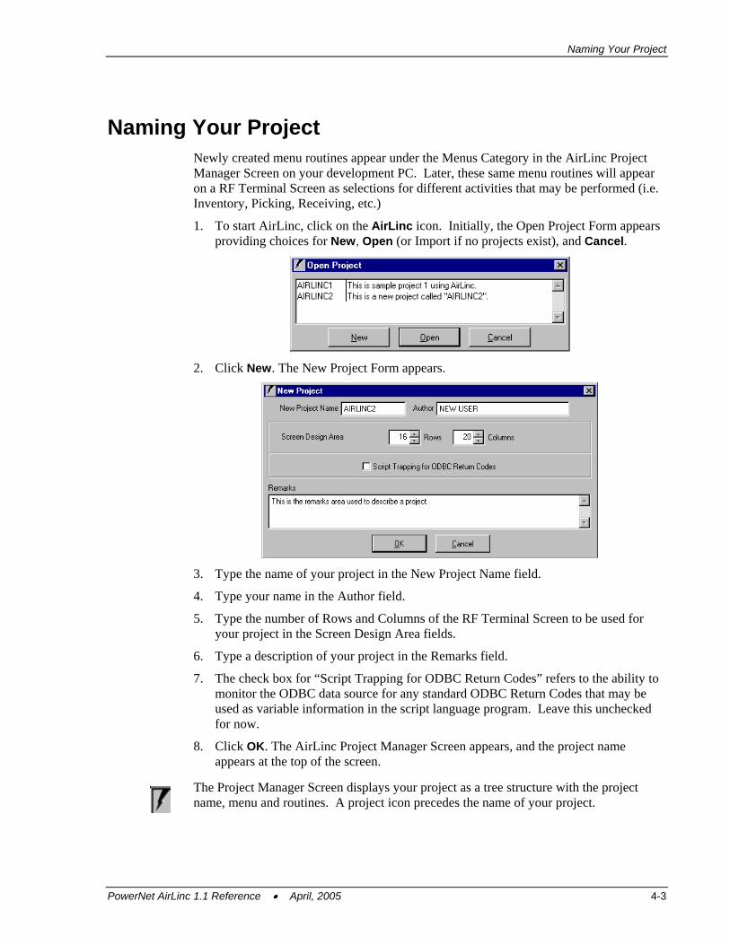
1. To start AirLinc, click on the AirLinc icon. Initially, the Open Project Form appears providing choices for New, Open (or Import if no projects exist), and Cancel.
2. Click New. The New Project Form appears.
3. Type the name of your project in the New Project Name field.
4. Type your name in the Author field.
5. Type the number of Rows and Columns of the RF Terminal Screen to be used for your project in the Screen Design Area fields.
6. Type a description of your project in the Remarks field.
7. The check box for “Script Trapping for ODBC Return Codes” refers to the ability to monitor the ODBC data source for any standard ODBC Return Codes that may be used as variable information in the script language program. Leave this unchecked for now.
8. Click OK. The AirLinc Project Manager Screen appears, and the project name appears at the top of the screen.
The Project Manager Screen displays your project as a tree structure with the project
PowerN
name, menu and routines. A project icon precedes the name of your project.
et AirLinc 1.1 Reference • April, 2005 4-3
Building a Project
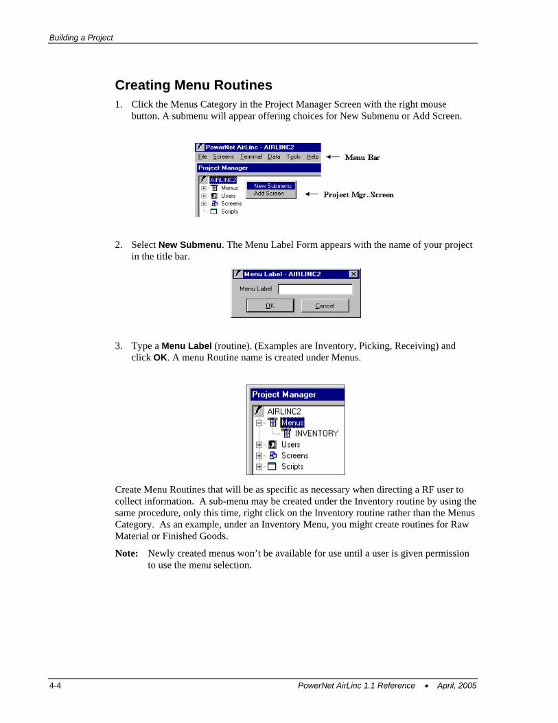
Creating Menu Routines 1. Click the Menus Category in the Project Manager Screen with the right mouse
button. A submenu will appear offering choices for New Submenu or Add Screen.
2. Select New Submenu. The Menu Label Form appears with the name of your project in the title bar.
3. Type a Menu Label (routine). (Examples are Inventory, Picking, Receiving) and click OK. A menu Routine name is created under Menus.
Create Menu Routines that will be as specific as necessary when directing a RF user to collect information. A sub-menu may be created under the Inventory routine by using the same procedure, only this time, right click on the Inventory routine rather than the Menus Category. As an example, under an Inventory Menu, you might create routines for Raw Material or Finished Goods.
Note: Newly created menus won’t be available for use until a user is given permission to use the menu selection.
4-4 PowerNet AirLinc 1.1 Reference • April, 2005
Creating Users and Groups
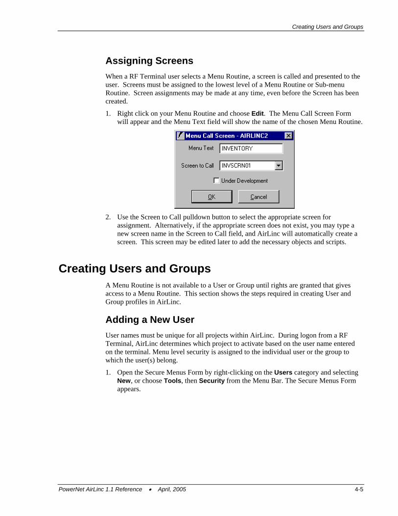
Assigning Screens When a RF Terminal user selects a Menu Routine, a screen is called and presented to the user. Screens must be assigned to the lowest level of a Menu Routine or Sub-menu Routine. Screen assignments may be made at any time, even before the Screen has been created.
1. Right click on your Menu Routine and choose Edit. The Menu Call Screen Form will appear and the Menu Text field will show the name of the chosen Menu Routine.
2. Use the Screen to Call pulldown button to select the appropriate screen for
assignment. Alternatively, if the appropriate screen does not exist, you may type a new screen name in the Screen to Call field, and AirLinc will automatically create a screen. This screen may be edited later to add the necessary objects and scripts.
Creating Users and Groups A Menu Routine is not available to a User or Group until rights are granted that gives access to a Menu Routine. This section shows the steps required in creating User and Group profiles in AirLinc.
Adding a New User User names must be unique for all projects within AirLinc. During logon from a RF Terminal, AirLinc determines which project to activate based on the user name entered on the terminal. Menu level security is assigned to the individual user or the group to which the user(s) belong.
1. Open the Secure Menus Form by right-clicking on the Users category and selecting New, or choose Tools, then Security from the Menu Bar. The Secure Menus Form appears.
PowerNet AirLinc 1.1 Reference • April, 2005 4-5
Building a Project
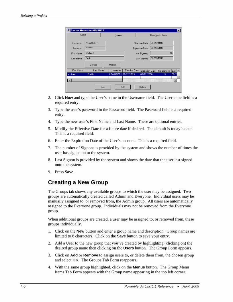
2. Click New and type the User’s name in the Username field. The Username field is a
required entry.
3. Type the user’s password in the Password field. The Password field is a required entry.
4. Type the new user’s First Name and Last Name. These are optional entries.
5. Modify the Effective Date for a future date if desired. The default is today’s date. This is a required field.
6. Enter the Expiration Date of the User’s account. This is a required field.
7. The number of Signons is provided by the system and shows the number of times the user has signed on to the system.
8. Last Signon is provided by the system and shows the date that the user last signed onto the system.
9. Press Save.
Creating a New Group The Groups tab shows any available groups to which the user may be assigned. Two groups are automatically created called Admin and Everyone. Individual users may be manually assigned to, or removed from, the Admin group. All users are automatically assigned to the Everyone group. Individuals may not be removed from the Everyone group.
When additional groups are created, a user may be assigned to, or removed from, these groups individually.
1. Click on the New button and enter a group name and description. Group names are limited to 8 characters. Click on the Save button to save your entry.
2. Add a User to the new group that you’ve created by highlighting (clicking on) the desired group name then clicking on the Users button. The Group Form appears.
3. Click on Add or Remove to assign users to, or delete them from, the chosen group and select OK. The Groups Tab Form reappears.
4. With the same group highlighted, click on the Menus button. The Group Menu Items Tab Form appears with the Group name appearing in the top left corner.
4-6 PowerNet AirLinc 1.1 Reference • April, 2005
Creating Screens
5. Click on any Menu Selection (Inventory, etc.) that you’d like to activate for the group, and click on the Save button.
Note: All Menu Routines are automatically enabled (checked) for the Admin Group and the Everyone Group. Menu Routines may not be disabled from the Admin Group, however, only a select group of users would typically be assigned to the Admin Group. Menu items may be disabled (un-checked) for the Everyone Group where all users are assigned. The Everyone Group typically has menu routines assigned that are required by all users.
6. Return to the Users tab and highlight any Menu Routine for assignment to an individual user.
Note: Menu routines may be enabled for Individual users, even though the user may not belong to any specialized group.
7. Click on the Menus button. The Users Menu Items Tab Form appears with the Users name appearing in the top left corner.
8. Click on any Menu selection (Inventory, etc.) that you’d like to enable (check) for the user, and click on the Save button.
9. Click on the close box in the upper right corner to exit the Secure Menus Form.
Modifying User Information On the Secure Menus Form, you may modify user information and parameters as well as add and delete users. Follow these steps to modify information about a user already entered on your project.
1. In the Project Manager Screen, double-click on Users, and a complete list of project users appears.
2. Double-click on the user name that you wish to modify. The Secure Menus Form appears with the user information displayed.
3. Edit or modify the information and click on Save to save your changes.
4. If you don't want to save your changes, close the Secure Menus Form by clicking on the close box in the upper right corner of the form.
Creating Screens You will use and reuse the information in Creating Screens, Testing Your Project, Creating an ODBC Data Source, and Creating Scripts to continuously refine your project. Initially, you need to develop a screen within AirLinc, assign that screen to a menu selection, and then test your project using the AirLinc Simulator.
When you create screens using the Screen Design Form, you are creating a screen that will appear identically to what will be displayed on the RF Terminal Screen. These screens contain Text Objects, Prompt Objects, and List Box Objects.
This section describes how to design screens for your RF Terminals. After generating your basic screens, and assigning these screens to a menu selection, you need to test your project using the AirLinc Simulator. Later, you may establish an ODBC System Data Source Name and create AirLinc Scripts for advanced data manipulation.
PowerNet AirLinc 1.1 Reference • April, 2005 4-7
Building a Project
Creating a New Screen The following steps describe how to create a new AirLinc Screen.
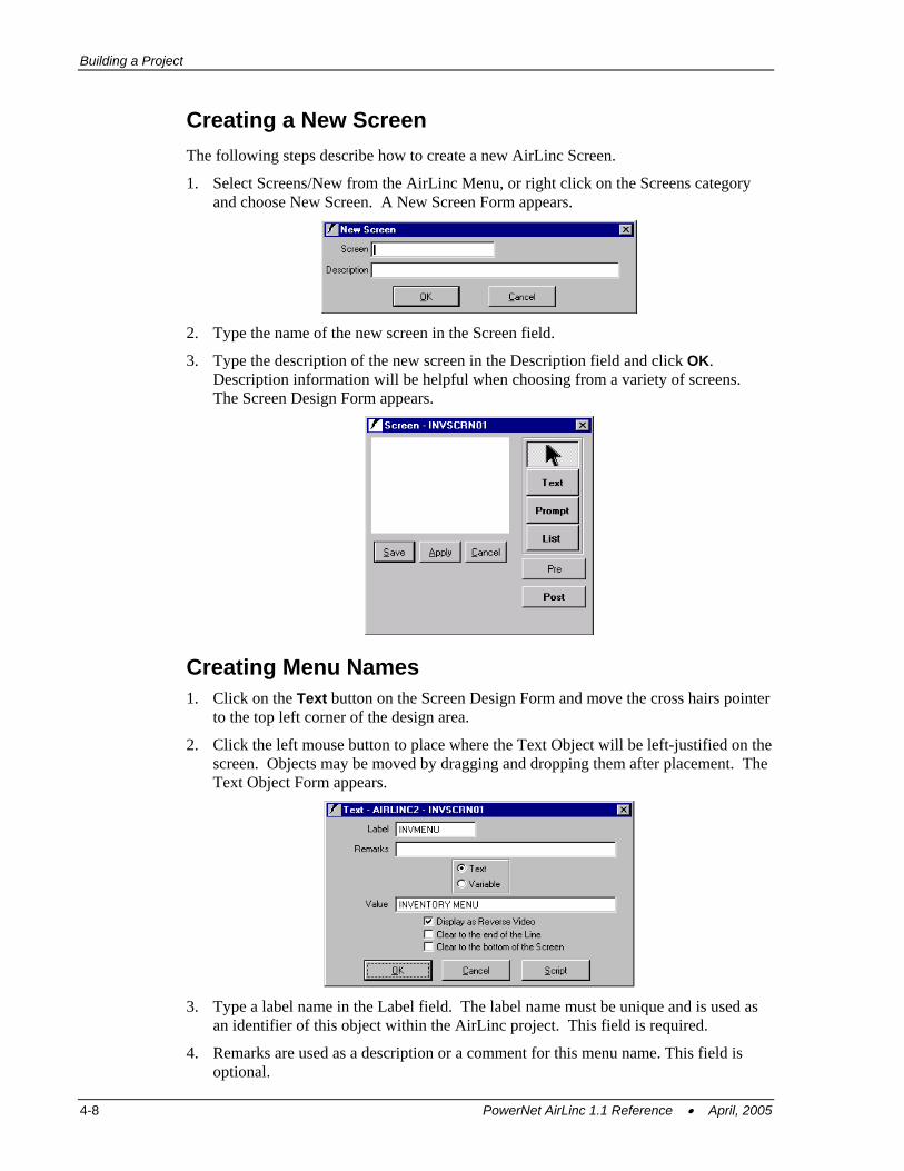
1. Select Screens/New from the AirLinc Menu, or right click on the Screens category and choose New Screen. A New Screen Form appears.
2. Type the name of the new screen in the Screen field.
3. Type the description of the new screen in the Description field and click OK. Description information will be helpful when choosing from a variety of screens. The Screen Design Form appears.
Creating Menu Names 1. Click on the Text button on the Screen Design Form and move the cross hairs pointer
to the top left corner of the design area.
2. Click the left mouse button to place where the Text Object will be left-justified on the screen. Objects may be moved by dragging and dropping them after placement. The Text Object Form appears.
3. Type a label name in the Label field. The label name must be unique and is used as
an identifier of this object within the AirLinc project. This field is required.
4. Remarks are used as a description or a comment for this menu name. This field is optional.
4-8 PowerNet AirLinc 1.1 Reference • April, 2005
Creating Screens
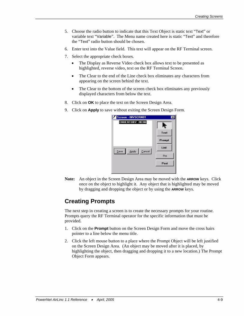
5. Choose the radio button to indicate that this Text Object is static text “Text” or variable text “Variable”. The Menu name created here is static “Text” and therefore the “Text” radio button should be chosen.
6. Enter text into the Value field. This text will appear on the RF Terminal screen.
7. Select the appropriate check boxes. • The Display as Reverse Video check box allows text to be presented as
highlighted, reverse video, text on the RF Terminal Screen.
• The Clear to the end of the Line check box eliminates any characters from appearing on the screen behind the text.
• The Clear to the bottom of the screen check box eliminates any previously displayed characters from below the text.
8. Click on OK to place the text on the Screen Design Area.
9. Click on Apply to save without exiting the Screen Design Form.
Note: An object in the Screen Design Area may be moved with the ARROW keys. Click once on the object to highlight it. Any object that is highlighted may be moved by dragging and dropping the object or by using the ARROW keys.
Creating Prompts The next step in creating a screen is to create the necessary prompts for your routine. Prompts query the RF Terminal operator for the specific information that must be provided.
1. Click on the Prompt button on the Screen Design Form and move the cross hairs pointer to a line below the menu title.
2. Click the left mouse button to a place where the Prompt Object will be left justified on the Screen Design Area. (An object may be moved after it is placed, by highlighting the object, then dragging and dropping it to a new location.) The Prompt Object Form appears.
PowerNet AirLinc 1.1 Reference • April, 2005 4-9
Building a Project
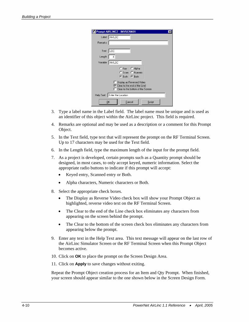
3. Type a label name in the Label field. The label name must be unique and is used as
an identifier of this object within the AirLinc project. This field is required.
4. Remarks are optional and may be used as a description or a comment for this Prompt Object.
5. In the Text field, type text that will represent the prompt on the RF Terminal Screen. Up to 17 characters may be used for the Text field.
6. In the Length field, type the maximum length of the input for the prompt field.
7. As a project is developed, certain prompts such as a Quantity prompt should be designed, in most cases, to only accept keyed, numeric information. Select the appropriate radio buttons to indicate if this prompt will accept: • Keyed entry, Scanned entry or Both.
• Alpha characters, Numeric characters or Both.
8. Select the appropriate check boxes. • The Display as Reverse Video check box will show your Prompt Object as
highlighted, reverse video text on the RF Terminal Screen.
• The Clear to the end of the Line check box eliminates any characters from appearing on the screen behind the prompt.
• The Clear to the bottom of the screen check box eliminates any characters from appearing below the prompt.
9. Enter any text in the Help Text area. This text message will appear on the last row of the AirLinc Simulator Screen or the RF Terminal Screen when this Prompt Object becomes active.
10. Click on OK to place the prompt on the Screen Design Area.
11. Click on Apply to save changes without exiting.
Repeat the Prompt Object creation process for an Item and Qty Prompt. When finished, your screen should appear similar to the one shown below in the Screen Design Form.
4-10 PowerNet AirLinc 1.1 Reference • April, 2005
Building Scripts
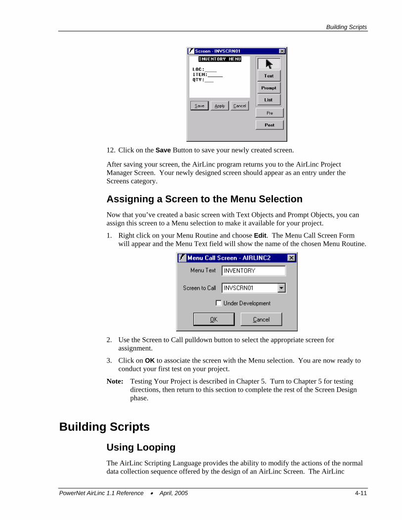
12. Click on the Save Button to save your newly created screen.
After saving your screen, the AirLinc program returns you to the AirLinc Project Manager Screen. Your newly designed screen should appear as an entry under the Screens category.
Assigning a Screen to the Menu Selection Now that you’ve created a basic screen with Text Objects and Prompt Objects, you can assign this screen to a Menu selection to make it available for your project.
1. Right click on your Menu Routine and choose Edit. The Menu Call Screen Form will appear and the Menu Text field will show the name of the chosen Menu Routine.
2. Use the Screen to Call pulldown button to select the appropriate screen for
assignment.
3. Click on OK to associate the screen with the Menu selection. You are now ready to conduct your first test on your project.
Note: Testing Your Project is described in Chapter 5. Turn to Chapter 5 for testing directions, then return to this section to complete the rest of the Screen Design phase.
Building Scripts Using Looping The AirLinc Scripting Language provides the ability to modify the actions of the normal data collection sequence offered by the design of an AirLinc Screen. The AirLinc
PowerNet AirLinc 1.1 Reference • April, 2005 4-11
Building a Project
Scripting Language Commands are discussed in Chapter 7, Creating Scripts, which are referenced from this chapter when modifying your AirLinc project.
For an example of building scripts: • Make the Inventory application loop from the QTY field to the LOC field when
collecting Inventory records. • Establish an ODBC connection. • Validate against a database table to make sure that you are entering a proper Item. • Create a script to add records to an Inventory records table.
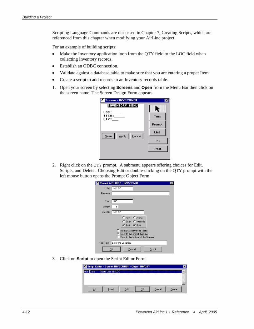
1. Open your screen by selecting Screens and Open from the Menu Bar then click on the screen name. The Screen Design Form appears.
2. Right click on the QTY prompt. A submenu appears offering choices for Edit,
Scripts, and Delete. Choosing Edit or double-clicking on the QTY prompt with the left mouse button opens the Prompt Object Form.
3. Click on Script to open the Script Editor Form.
4-12 PowerNet AirLinc 1.1 Reference • April, 2005
Building Scripts
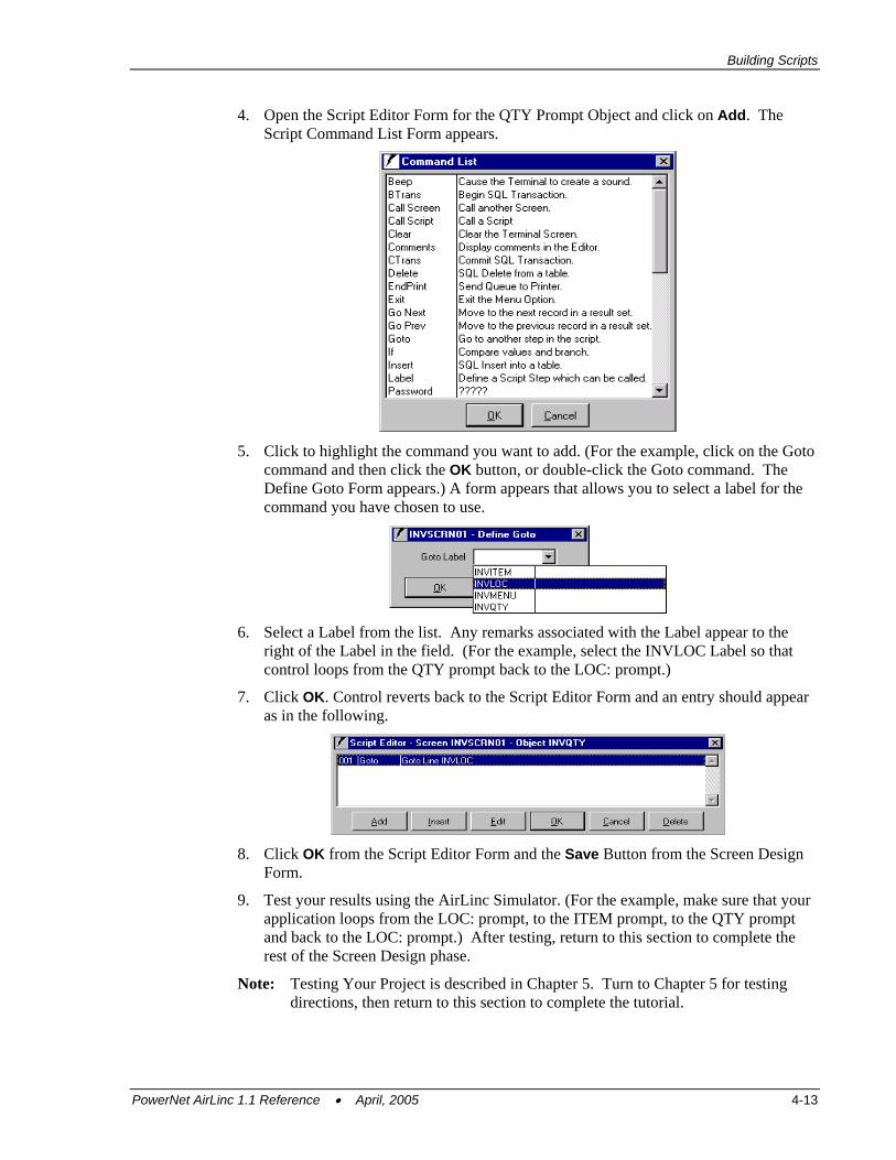
4. Open the Script Editor Form for the QTY Prompt Object and click on Add. The Script Command List Form appears.
5. Click to highlight the command you want to add. (For the example, click on the Goto
command and then click the OK button, or double-click the Goto command. The Define Goto Form appears.) A form appears that allows you to select a label for the command you have chosen to use.
6. Select a Label from the list. Any remarks associated with the Label appear to the
right of the Label in the field. (For the example, select the INVLOC Label so that control loops from the QTY prompt back to the LOC: prompt.)
7. Click OK. Control reverts back to the Script Editor Form and an entry should appear as in the following.
8. Click OK from the Script Editor Form and the Save Button from the Screen Design
Form.
9. Test your results using the AirLinc Simulator. (For the example, make sure that your application loops from the LOC: prompt, to the ITEM prompt, to the QTY prompt and back to the LOC: prompt.) After testing, return to this section to complete the rest of the Screen Design phase.
Note: Testing Your Project is described in Chapter 5. Turn to Chapter 5 for testing directions, then return to this section to complete the tutorial.
PowerNet AirLinc 1.1 Reference • April, 2005 4-13
Building a Project
Creating an Exit from the Routine You may have discovered that the Inventory routine that you created does not allow an escape from the sequence. The only way to exit the Simulator is to click on the close form button in the top right hand corner of the Simulator.
(For the example, the next goal is to create a script that gives an exit from the Inventory routine so that you would be able to choose another Menu selection if it were available.)
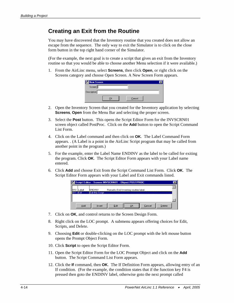
1. From the AirLinc menu, select Screens, then click Open, or right click on the Screens category and choose Open Screen. A New Screen Form appears.
2. Open the Inventory Screen that you created for the Inventory application by selecting
Screens, Open from the Menu Bar and selecting the proper screen.
3. Select the Post button. This opens the Script Editor Form for the INVSCRN01 screen object called PostProc. Click on the Add button to open the Script Command List Form.
4. Click on the Label command and then click on OK. The Label Command Form appears. . (A Label is a point in the AirLinc Script program that may be called from another point in the program.)
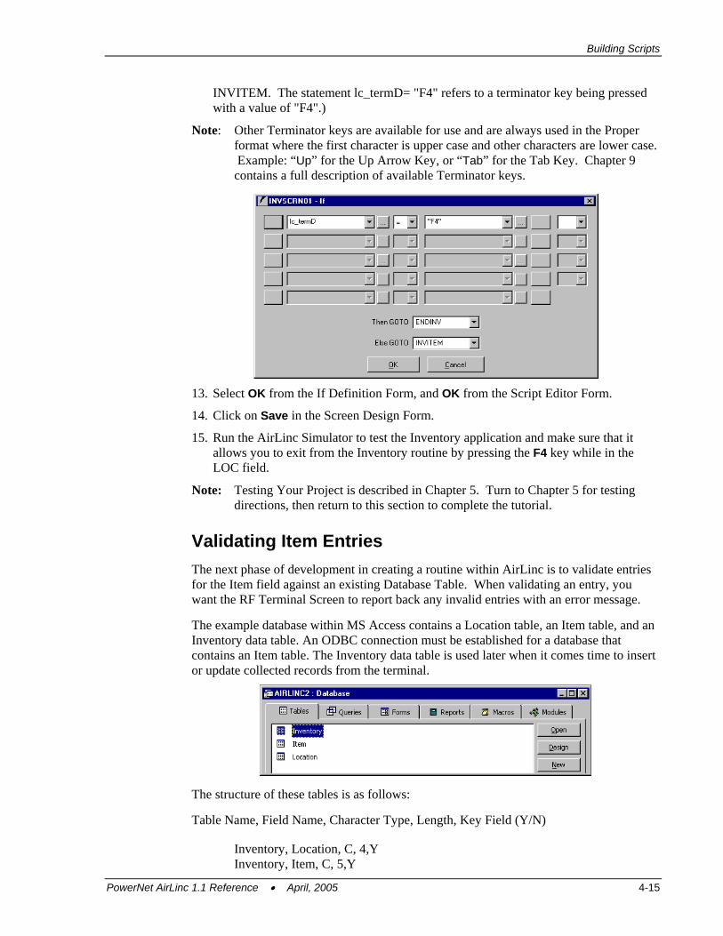
5. For the example, enter the Label Name ENDINV as the label to be called for exiting the program. Click OK. The Script Editor Form appears with your Label name entered.
6. Click Add and choose Exit from the Script Command List Form. Click OK. The Script Editor Form appears with your Label and Exit commands listed.
7. Click on OK, and control returns to the Screen Design Form.
8. Right click on the LOC prompt. A submenu appears offering choices for Edit, Scripts, and Delete.
9. Choosing Edit or double-clicking on the LOC prompt with the left mouse button opens the Prompt Object Form.
10. Click Script to open the Script Editor Form.
11. Open the Script Editor Form for the LOC Prompt Object and click on the Add button. The Script Command List Form appears.
12. Click the If command, then OK. The If Definition Form appears, allowing entry of an If condition. (For the example, the condition states that if the function key F4 is pressed then goto the ENDINV label, otherwise goto the next prompt called
4-14 PowerNet AirLinc 1.1 Reference • April, 2005
Building Scripts
INVITEM. The statement lc_termD= "F4" refers to a terminator key being pressed with a value of "F4".)
Note: Other Terminator keys are available for use and are always used in the Proper format where the first character is upper case and other characters are lower case. Example: “Up” for the Up Arrow Key, or “Tab” for the Tab Key. Chapter 9 contains a full description of available Terminator keys.
13. Select OK from the If Definition Form, and OK from the Script Editor Form.
14. Click on Save in the Screen Design Form.
15. Run the AirLinc Simulator to test the Inventory application and make sure that it allows you to exit from the Inventory routine by pressing the F4 key while in the LOC field.
Note: Testing Your Project is described in Chapter 5. Turn to Chapter 5 for testing directions, then return to this section to complete the tutorial.
Validating Item Entries The next phase of development in creating a routine within AirLinc is to validate entries for the Item field against an existing Database Table. When validating an entry, you want the RF Terminal Screen to report back any invalid entries with an error message.
The example database within MS Access contains a Location table, an Item table, and an Inventory data table. An ODBC connection must be established for a database that contains an Item table. The Inventory data table is used later when it comes time to insert or update collected records from the terminal.
The structure of these tables is as follows:
Table Name, Field Name, Character Type, Length, Key Field (Y/N)
Inventory, Location, C, 4,Y Inventory, Item, C, 5,Y
PowerNet AirLinc 1.1 Reference • April, 2005 4-15
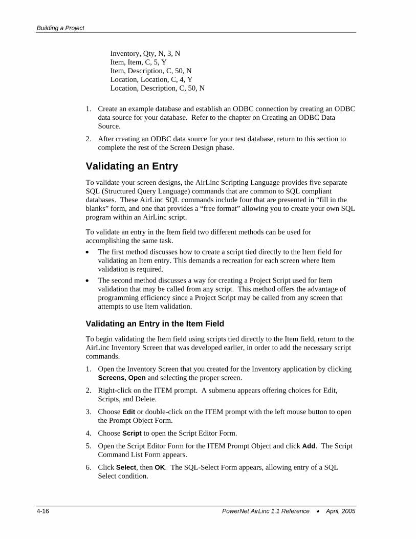
Building a Project
Inventory, Qty, N, 3, N Item, Item, C, 5, Y Item, Description, C, 50, N Location, Location, C, 4, Y Location, Description, C, 50, N
1. Create an example database and establish an ODBC connection by creating an ODBC data source for your database. Refer to the chapter on Creating an ODBC Data Source.
2. After creating an ODBC data source for your test database, return to this section to complete the rest of the Screen Design phase.
Validating an Entry To validate your screen designs, the AirLinc Scripting Language provides five separate SQL (Structured Query Language) commands that are common to SQL compliant databases. These AirLinc SQL commands include four that are presented in “fill in the blanks” form, and one that provides a “free format” allowing you to create your own SQL program within an AirLinc script.
To validate an entry in the Item field two different methods can be used for accomplishing the same task. • The first method discusses how to create a script tied directly to the Item field for
validating an Item entry. This demands a recreation for each screen where Item validation is required.
• The second method discusses a way for creating a Project Script used for Item validation that may be called from any script. This method offers the advantage of programming efficiency since a Project Script may be called from any screen that attempts to use Item validation.
Validating an Entry in the Item Field
To begin validating the Item field using scripts tied directly to the Item field, return to the AirLinc Inventory Screen that was developed earlier, in order to add the necessary script commands.
1. Open the Inventory Screen that you created for the Inventory application by clicking Screens, Open and selecting the proper screen.
2. Right-click on the ITEM prompt. A submenu appears offering choices for Edit, Scripts, and Delete.
3. Choose Edit or double-click on the ITEM prompt with the left mouse button to open the Prompt Object Form.
4. Choose Script to open the Script Editor Form.
5. Open the Script Editor Form for the ITEM Prompt Object and click Add. The Script Command List Form appears.
6. Click Select, then OK. The SQL-Select Form appears, allowing entry of a SQL Select condition.
4-16 PowerNet AirLinc 1.1 Reference • April, 2005
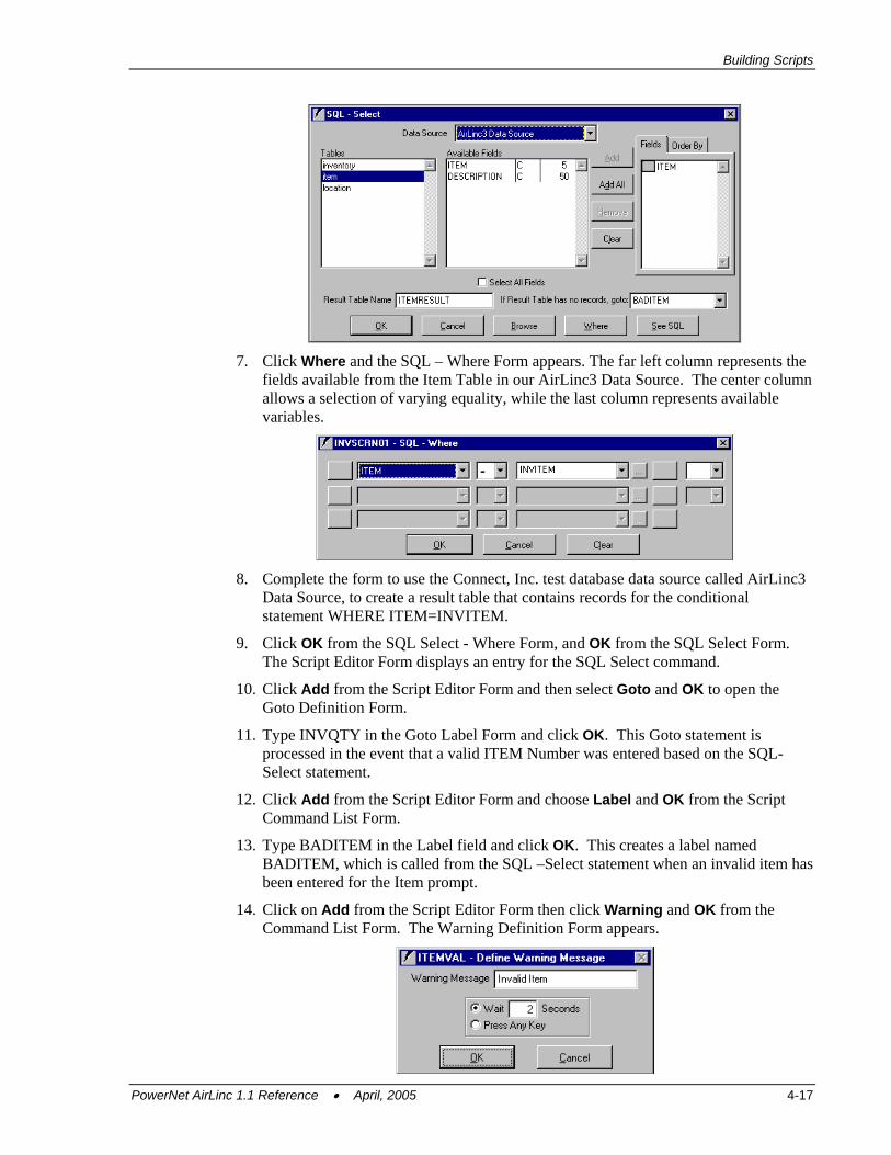
Building Scripts
7. Click Where and the SQL – Where Form appears. The far left column represents the
fields available from the Item Table in our AirLinc3 Data Source. The center column allows a selection of varying equality, while the last column represents available variables.
8. Complete the form to use the Connect, Inc. test database data source called AirLinc3
Data Source, to create a result table that contains records for the conditional statement WHERE ITEM=INVITEM.
9. Click OK from the SQL Select - Where Form, and OK from the SQL Select Form. The Script Editor Form displays an entry for the SQL Select command.
10. Click Add from the Script Editor Form and then select Goto and OK to open the Goto Definition Form.
11. Type INVQTY in the Goto Label Form and click OK. This Goto statement is processed in the event that a valid ITEM Number was entered based on the SQL-Select statement.
12. Click Add from the Script Editor Form and choose Label and OK from the Script Command List Form.
13. Type BADITEM in the Label field and click OK. This creates a label named BADITEM, which is called from the SQL –Select statement when an invalid item has been entered for the Item prompt.
14. Click on Add from the Script Editor Form then click Warning and OK from the Command List Form. The Warning Definition Form appears.
PowerNet AirLinc 1.1 Reference • April, 2005 4-17
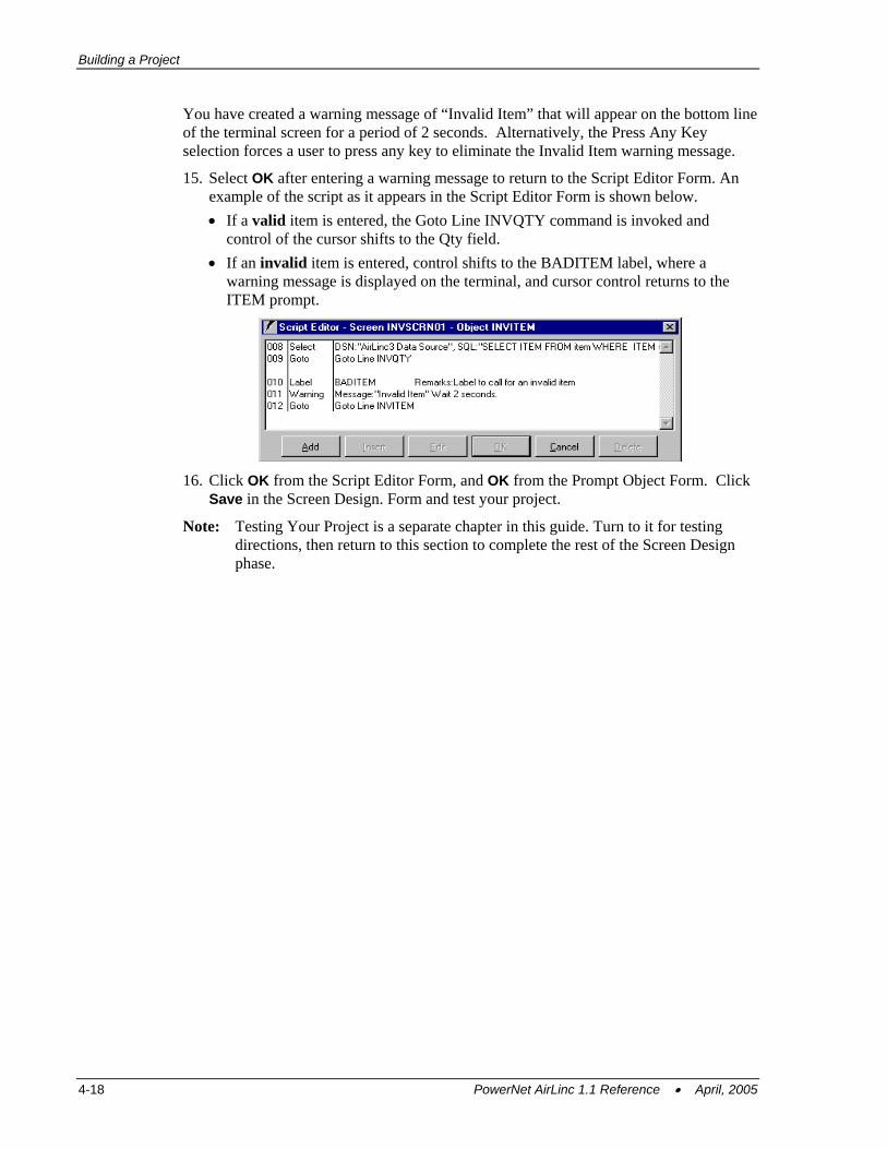
Building a Project
You have created a warning message of “Invalid Item” that will appear on the bottom line of the terminal screen for a period of 2 seconds. Alternatively, the Press Any Key selection forces a user to press any key to eliminate the Invalid Item warning message.
15. Select OK after entering a warning message to return to the Script Editor Form. An example of the script as it appears in the Script Editor Form is shown below. • If a valid item is entered, the Goto Line INVQTY command is invoked and
control of the cursor shifts to the Qty field. • If an invalid item is entered, control shifts to the BADITEM label, where a
warning message is displayed on the terminal, and cursor control returns to the ITEM prompt.
16. Click OK from the Script Editor Form, and OK from the Prompt Object Form. Click
Save in the Screen Design. Form and test your project.
Note: Testing Your Project is a separate chapter in this guide. Turn to it for testing directions, then return to this section to complete the rest of the Screen Design phase.
4-18 PowerNet AirLinc 1.1 Reference • April, 2005
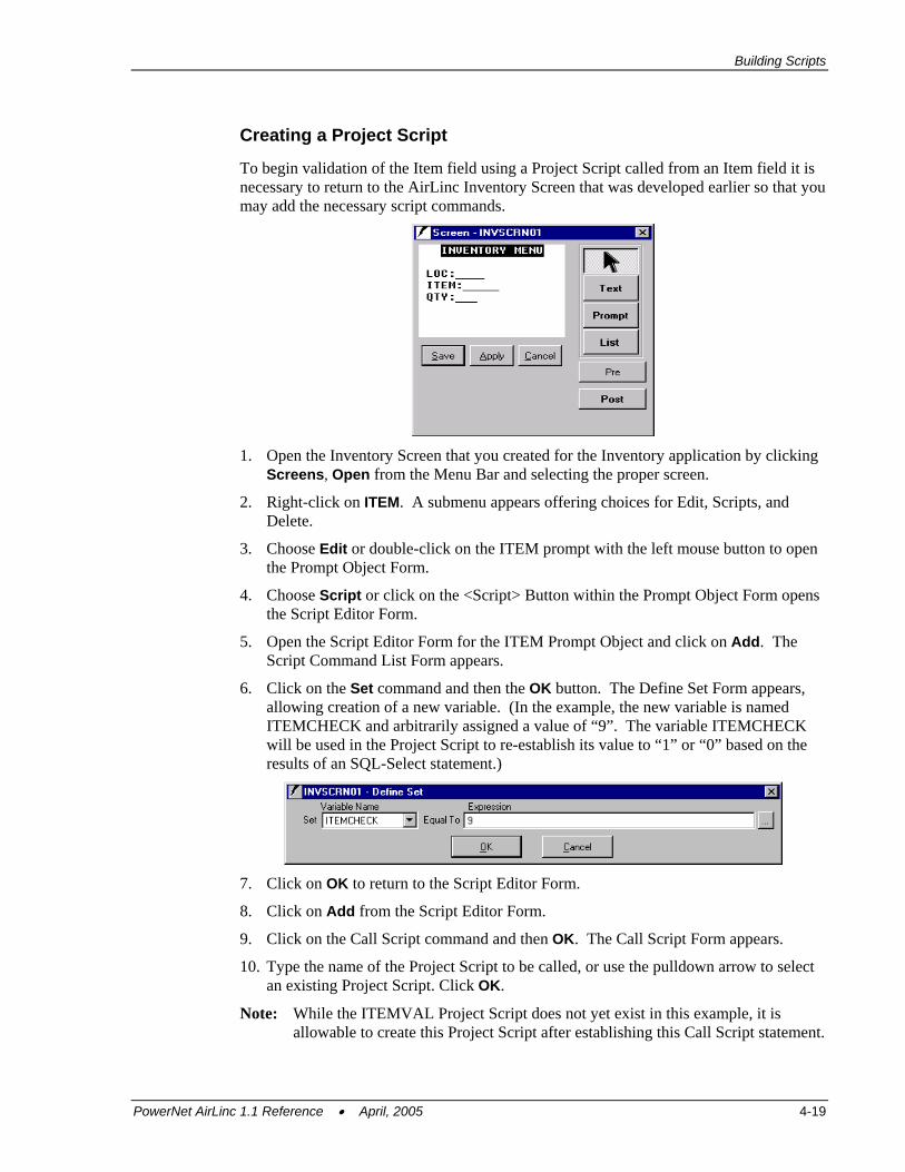
Building Scripts
Creating a Project Script
To begin validation of the Item field using a Project Script called from an Item field it is necessary to return to the AirLinc Inventory Screen that was developed earlier so that you may add the necessary script commands.
1. Open the Inventory Screen that you created for the Inventory application by clicking
Screens, Open from the Menu Bar and selecting the proper screen.
2. Right-click on ITEM. A submenu appears offering choices for Edit, Scripts, and Delete.
3. Choose Edit or double-click on the ITEM prompt with the left mouse button to open the Prompt Object Form.
4. Choose Script or click on the <Script> Button within the Prompt Object Form opens the Script Editor Form.
5. Open the Script Editor Form for the ITEM Prompt Object and click on Add. The Script Command List Form appears.
6. Click on the Set command and then the OK button. The Define Set Form appears, allowing creation of a new variable. (In the example, the new variable is named ITEMCHECK and arbitrarily assigned a value of “9”. The variable ITEMCHECK will be used in the Project Script to re-establish its value to “1” or “0” based on the results of an SQL-Select statement.)
7. Click on OK to return to the Script Editor Form.
8. Click on Add from the Script Editor Form.
9. Click on the Call Script command and then OK. The Call Script Form appears.
10. Type the name of the Project Script to be called, or use the pulldown arrow to select an existing Project Script. Click OK.
Note: While the ITEMVAL Project Script does not yet exist in this example, it is allowable to create this Project Script after establishing this Call Script statement.
PowerNet AirLinc 1.1 Reference • April, 2005 4-19

Building a Project
11. Click Add from the Script Editor Form.
12. Click the If command and then OK. The If Definition Form appears.
13. Create an If statement that states: If our new variable ITEMCHECK = 0 Then GOTO INVITEM, Else GOTO INVQTY.
14. Click OK to return to the Script Editor Form.
15. Press OK at the Script Editor Form. Confirm that your Script Editor Form looks like the following sample.
16. Click OK from the Prompt Object Form, and Save from the Screen Design Form.
Note: Testing Your Project is a separate chapter in this guide. Turn to it for testing directions, then return to this section to complete the rest of the Screen Design phase.
Establishing a Project Script 1. Right-click on the Script category from the Project Manager Screen and select New
Script from the submenu. The Script Definition Form appears allowing creation of a Project Script name and a Description.
2. Enter the Project Script name and the Description. Click OK. A new entry should appear under the Script Category within the Project Manager Screen.
3. Right-click on the Project Script and select Edit from the submenu. The Script Editor Form appears.
4. Click Add to open the Script Command List Form.
5. Click Select then the OK button. The SQL-Select Form appears, allowing entry of a SQL Select condition. (The example states that using our test database data source called AirLinc3 Data Source, creates a result table that contains records for the conditional statement WHERE ITEM=INVITEM. This conditional statement is created by clicking on the Where button and completing the form.)
4-20 PowerNet AirLinc 1.1 Reference • April, 2005
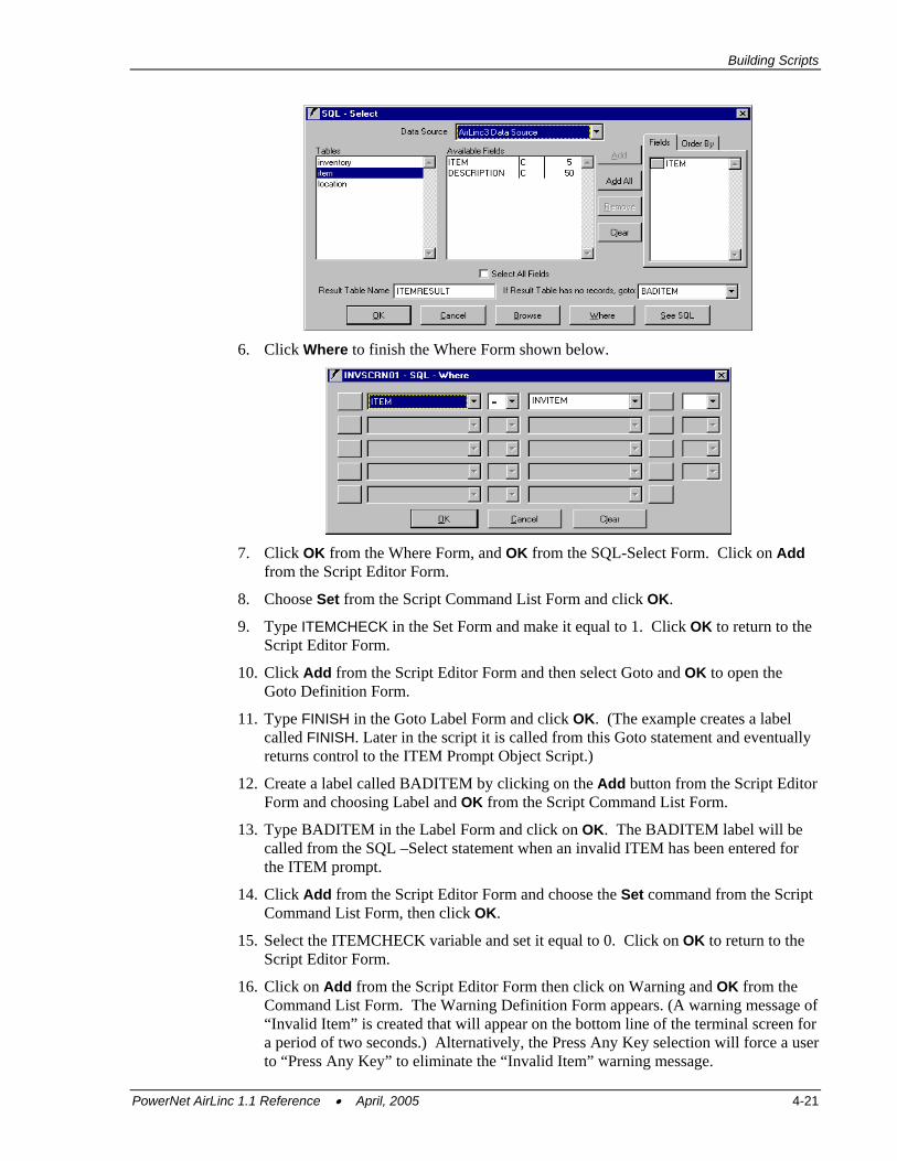
Building Scripts
6. Click Where to finish the Where Form shown below.
7. Click OK from the Where Form, and OK from the SQL-Select Form. Click on Add
from the Script Editor Form.
8. Choose Set from the Script Command List Form and click OK.
9. Type ITEMCHECK in the Set Form and make it equal to 1. Click OK to return to the Script Editor Form.
10. Click Add from the Script Editor Form and then select Goto and OK to open the Goto Definition Form.
11. Type FINISH in the Goto Label Form and click OK. (The example creates a label called FINISH. Later in the script it is called from this Goto statement and eventually returns control to the ITEM Prompt Object Script.)
12. Create a label called BADITEM by clicking on the Add button from the Script Editor Form and choosing Label and OK from the Script Command List Form.
13. Type BADITEM in the Label Form and click on OK. The BADITEM label will be called from the SQL –Select statement when an invalid ITEM has been entered for the ITEM prompt.
14. Click Add from the Script Editor Form and choose the Set command from the Script Command List Form, then click OK.
15. Select the ITEMCHECK variable and set it equal to 0. Click on OK to return to the Script Editor Form.
16. Click on Add from the Script Editor Form then click on Warning and OK from the Command List Form. The Warning Definition Form appears. (A warning message of “Invalid Item” is created that will appear on the bottom line of the terminal screen for a period of two seconds.) Alternatively, the Press Any Key selection will force a user to “Press Any Key” to eliminate the “Invalid Item” warning message.
PowerNet AirLinc 1.1 Reference • April, 2005 4-21
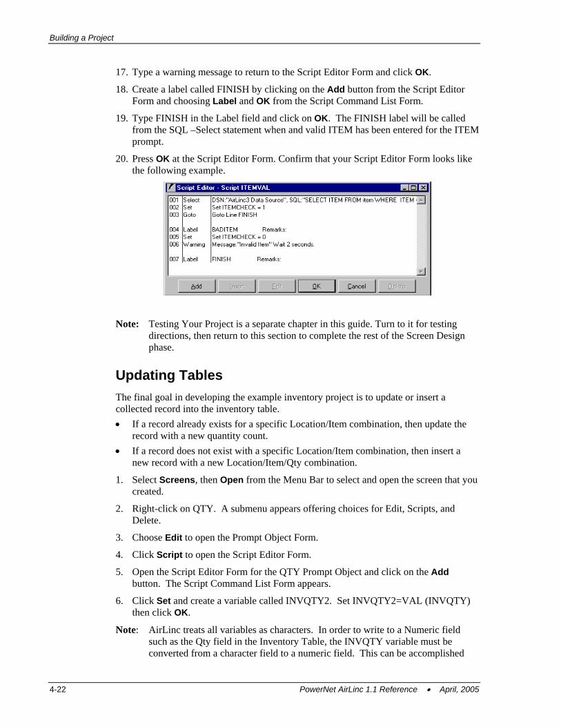
Building a Project
17. Type a warning message to return to the Script Editor Form and click OK.
18. Create a label called FINISH by clicking on the Add button from the Script Editor Form and choosing Label and OK from the Script Command List Form.
19. Type FINISH in the Label field and click on OK. The FINISH label will be called from the SQL –Select statement when and valid ITEM has been entered for the ITEM prompt.
20. Press OK at the Script Editor Form. Confirm that your Script Editor Form looks like the following example.
Note: Testing Your Project is a separate chapter in this guide. Turn to it for testing directions, then return to this section to complete the rest of the Screen Design phase.
Updating Tables The final goal in developing the example inventory project is to update or insert a collected record into the inventory table. • If a record already exists for a specific Location/Item combination, then update the
record with a new quantity count. • If a record does not exist with a specific Location/Item combination, then insert a
new record with a new Location/Item/Qty combination.
1. Select Screens, then Open from the Menu Bar to select and open the screen that you created.
2. Right-click on QTY. A submenu appears offering choices for Edit, Scripts, and Delete.
3. Choose Edit to open the Prompt Object Form.
4. Click Script to open the Script Editor Form.
5. Open the Script Editor Form for the QTY Prompt Object and click on the Add button. The Script Command List Form appears.
6. Click Set and create a variable called INVQTY2. Set INVQTY2=VAL (INVQTY) then click OK.
Note: AirLinc treats all variables as characters. In order to write to a Numeric field such as the Qty field in the Inventory Table, the INVQTY variable must be converted from a character field to a numeric field. This can be accomplished
4-22 PowerNet AirLinc 1.1 Reference • April, 2005
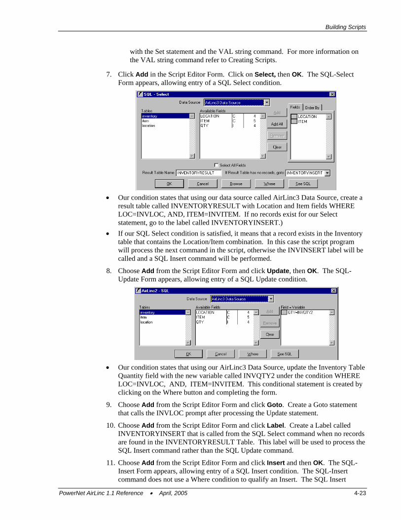
Building Scripts
with the Set statement and the VAL string command. For more information on the VAL string command refer to Creating Scripts.
7. Click Add in the Script Editor Form. Click on Select, then OK. The SQL-Select Form appears, allowing entry of a SQL Select condition.
• Our condition states that using our data source called AirLinc3 Data Source, create a
result table called INVENTORYRESULT with Location and Item fields WHERE LOC=INVLOC, AND, ITEM=INVITEM. If no records exist for our Select statement, go to the label called INVENTORYINSERT.)
• If our SQL Select condition is satisfied, it means that a record exists in the Inventory table that contains the Location/Item combination. In this case the script program will process the next command in the script, otherwise the INVINSERT label will be called and a SQL Insert command will be performed.
8. Choose Add from the Script Editor Form and click Update, then OK. The SQL-Update Form appears, allowing entry of a SQL Update condition.
• Our condition states that using our AirLinc3 Data Source, update the Inventory Table
Quantity field with the new variable called INVQTY2 under the condition WHERE LOC=INVLOC, AND, ITEM=INVITEM. This conditional statement is created by clicking on the Where button and completing the form.
9. Choose Add from the Script Editor Form and click Goto. Create a Goto statement that calls the INVLOC prompt after processing the Update statement.
10. Choose Add from the Script Editor Form and click Label. Create a Label called INVENTORYINSERT that is called from the SQL Select command when no records are found in the INVENTORYRESULT Table. This label will be used to process the SQL Insert command rather than the SQL Update command.
11. Choose Add from the Script Editor Form and click Insert and then OK. The SQL-Insert Form appears, allowing entry of a SQL Insert condition. The SQL-Insert command does not use a Where condition to qualify an Insert. The SQL Insert
PowerNet AirLinc 1.1 Reference • April, 2005 4-23
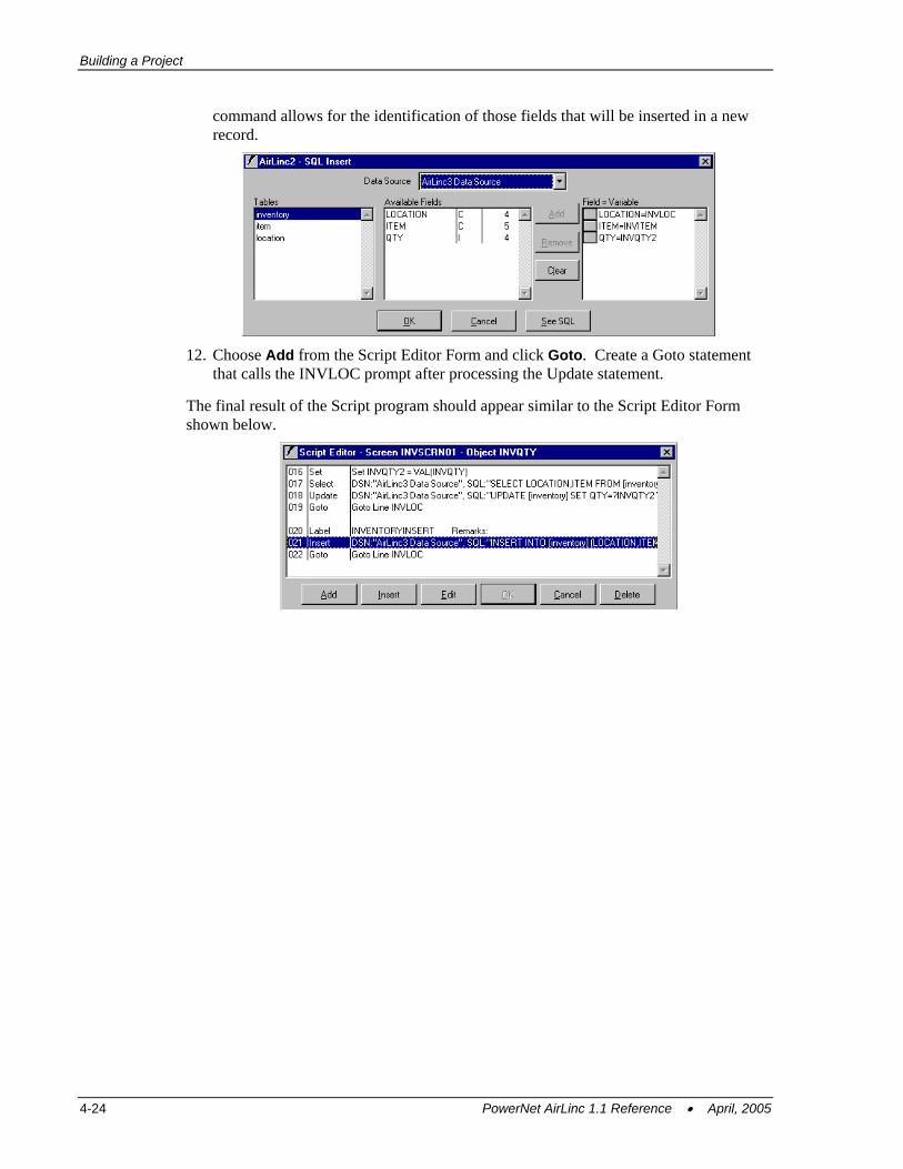
Building a Project
command allows for the identification of those fields that will be inserted in a new record.
12. Choose Add from the Script Editor Form and click Goto. Create a Goto statement
that calls the INVLOC prompt after processing the Update statement.
The final result of the Script program should appear similar to the Script Editor Form shown below.
4-24 PowerNet AirLinc 1.1 Reference • April, 2005
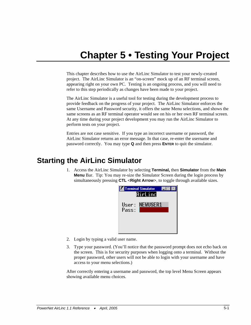
Chapter 5 • Testing Your Project This chapter describes how to use the AirLinc Simulator to test your newly-created project. The AirLinc Simulator is an “on-screen” mock up of an RF terminal screen, appearing right on your own PC. Testing is an ongoing process, and you will need to refer to this step periodically as changes have been made to your project.
The AirLinc Simulator is a useful tool for testing during the development process to provide feedback on the progress of your project. The AirLinc Simulator enforces the same Username and Password security, it offers the same Menu selections, and shows the same screens as an RF terminal operator would see on his or her own RF terminal screen. At any time during your project development you may run the AirLinc Simulator to perform tests on your project.
Entries are not case sensitive. If you type an incorrect username or password, the AirLinc Simulator returns an error message. In that case, re-enter the username and password correctly. You may type Q and then press ENTER to quit the simulator.
Starting the AirLinc Simulator 1. Access the AirLinc Simulator by selecting Terminal, then Simulator from the Main
Menu Bar. Tip: You may re-size the Simulator Screen during the login process by simultaneously pressing CTL <Right Arrow>, to toggle through available sizes.
2. Login by typing a valid user name.
3. Type your password. (You’ll notice that the password prompt does not echo back on the screen. This is for security purposes when logging onto a terminal. Without the proper password, other users will not be able to login with your username and have access to your menu selections.)
After correctly entering a username and password, the top level Menu Screen appears showing available menu choices.
PowerNet AirLinc 1.1 Reference • April, 2005 5-1
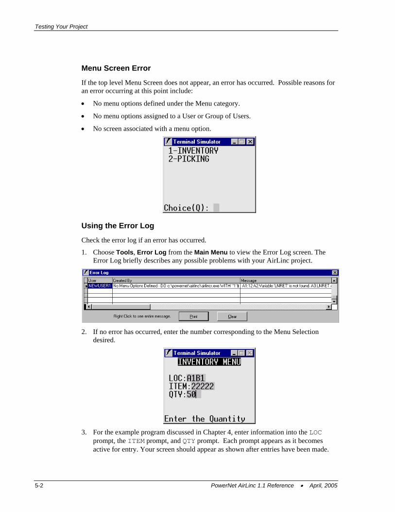
Testing Your Project
Menu Screen Error
If the top level Menu Screen does not appear, an error has occurred. Possible reasons for an error occurring at this point include:
• No menu options defined under the Menu category.
• No menu options assigned to a User or Group of Users.
• No screen associated with a menu option.
Using the Error Log
Check the error log if an error has occurred.
1. Choose Tools, Error Log from the Main Menu to view the Error Log screen. The Error Log briefly describes any possible problems with your AirLinc project.
2. If no error has occurred, enter the number corresponding to the Menu Selection
desired.
3. For the example program discussed in Chapter 4, enter information into the LOC
prompt, the ITEM prompt, and QTY prompt. Each prompt appears as it becomes active for entry. Your screen should appear as shown after entries have been made.
5-2 PowerNet AirLinc 1.1 Reference • April, 2005

Starting the AirLinc Simulator
Note: Based on the level of scripting created at this point, the program may appear or react differently than this basic example. Use of the AirLinc Simulator allows you to test the current project and make corrections if necessary.
PowerNet AirLinc 1.1 Reference • April, 2005 5-3

Testing Your Project
This page is intentionally blank.
5-4 PowerNet AirLinc 1.1 Reference • April, 2005
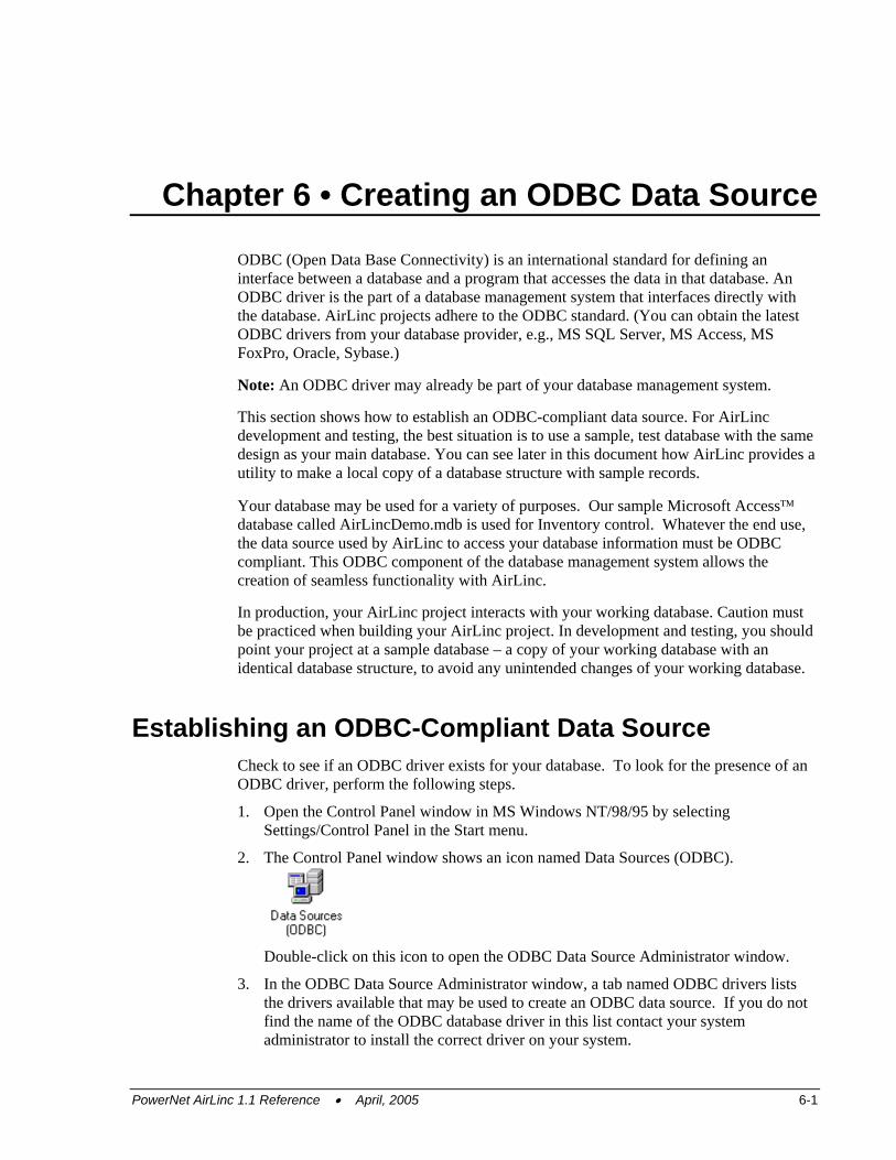
Chapter 6 • Creating an ODBC Data Source
ODBC (Open Data Base Connectivity) is an international standard for defining an interface between a database and a program that accesses the data in that database. An ODBC driver is the part of a database management system that interfaces directly with the database. AirLinc projects adhere to the ODBC standard. (You can obtain the latest ODBC drivers from your database provider, e.g., MS SQL Server, MS Access, MS FoxPro, Oracle, Sybase.)
Note: An ODBC driver may already be part of your database management system.
This section shows how to establish an ODBC-compliant data source. For AirLinc development and testing, the best situation is to use a sample, test database with the same design as your main database. You can see later in this document how AirLinc provides a utility to make a local copy of a database structure with sample records.
Your database may be used for a variety of purposes. Our sample Microsoft Access™ database called AirLincDemo.mdb is used for Inventory control. Whatever the end use, the data source used by AirLinc to access your database information must be ODBC compliant. This ODBC component of the database management system allows the creation of seamless functionality with AirLinc.
In production, your AirLinc project interacts with your working database. Caution must be practiced when building your AirLinc project. In development and testing, you should point your project at a sample database – a copy of your working database with an identical database structure, to avoid any unintended changes of your working database.
Establishing an ODBC-Compliant Data Source Check to see if an ODBC driver exists for your database. To look for the presence of an ODBC driver, perform the following steps.
1. Open the Control Panel window in MS Windows NT/98/95 by selecting Settings/Control Panel in the Start menu.
2. The Control Panel window shows an icon named Data Sources (ODBC).
Double-click on this icon to open the ODBC Data Source Administrator window.
3. In the ODBC Data Source Administrator window, a tab named ODBC drivers lists the drivers available that may be used to create an ODBC data source. If you do not find the name of the ODBC database driver in this list contact your system administrator to install the correct driver on your system.
PowerNet AirLinc 1.1 Reference • April, 2005 6-1
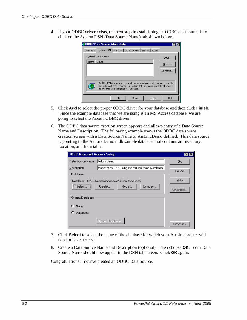
Creating an ODBC Data Source
4. If your ODBC driver exists, the next step in establishing an ODBC data source is to click on the System DSN (Data Source Name) tab shown below.
5. Click Add to select the proper ODBC driver for your database and then click Finish.
Since the example database that we are using is an MS Access database, we are going to select the Access ODBC driver.
6. The ODBC data source creation screen appears and allows entry of a Data Source Name and Description. The following example shows the ODBC data source creation screen with a Data Source Name of AirLincDemo defined. This data source is pointing to the AirLincDemo.mdb sample database that contains an Inventory, Location, and Item table.
7. Click Select to select the name of the database for which your AirLinc project will
need to have access.
8. Create a Data Source Name and Description (optional). Then choose OK. Your Data Source Name should now appear in the DSN tab screen. Click OK again.
Congratulations! You’ve created an ODBC Data Source.
6-2 PowerNet AirLinc 1.1 Reference • April, 2005
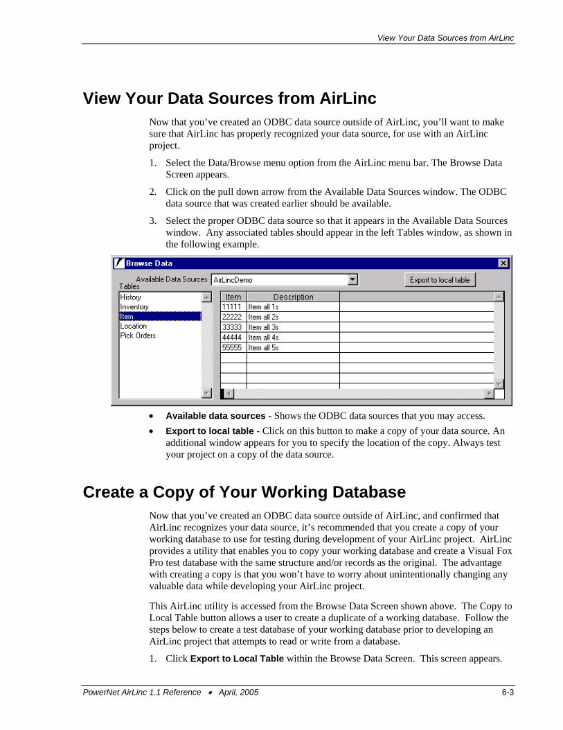
View Your Data Sources from AirLinc
View Your Data Sources from AirLinc Now that you’ve created an ODBC data source outside of AirLinc, you’ll want to make sure that AirLinc has properly recognized your data source, for use with an AirLinc project.
1. Select the Data/Browse menu option from the AirLinc menu bar. The Browse Data Screen appears.
2. Click on the pull down arrow from the Available Data Sources window. The ODBC data source that was created earlier should be available.
3. Select the proper ODBC data source so that it appears in the Available Data Sources window. Any associated tables should appear in the left Tables window, as shown in the following example.
• Available data sources - Shows the ODBC data sources that you may access. • Export to local table - Click on this button to make a copy of your data source. An
additional window appears for you to specify the location of the copy. Always test your project on a copy of the data source.
Create a Copy of Your Working Database Now that you’ve created an ODBC data source outside of AirLinc, and confirmed that AirLinc recognizes your data source, it’s recommended that you create a copy of your working database to use for testing during development of your AirLinc project. AirLinc provides a utility that enables you to copy your working database and create a Visual Fox Pro test database with the same structure and/or records as the original. The advantage with creating a copy is that you won’t have to worry about unintentionally changing any valuable data while developing your AirLinc project.
This AirLinc utility is accessed from the Browse Data Screen shown above. The Copy to Local Table button allows a user to create a duplicate of a working database. Follow the steps below to create a test database of your working database prior to developing an AirLinc project that attempts to read or write from a database.
1. Click Export to Local Table within the Browse Data Screen. This screen appears.
PowerNet AirLinc 1.1 Reference • April, 2005 6-3
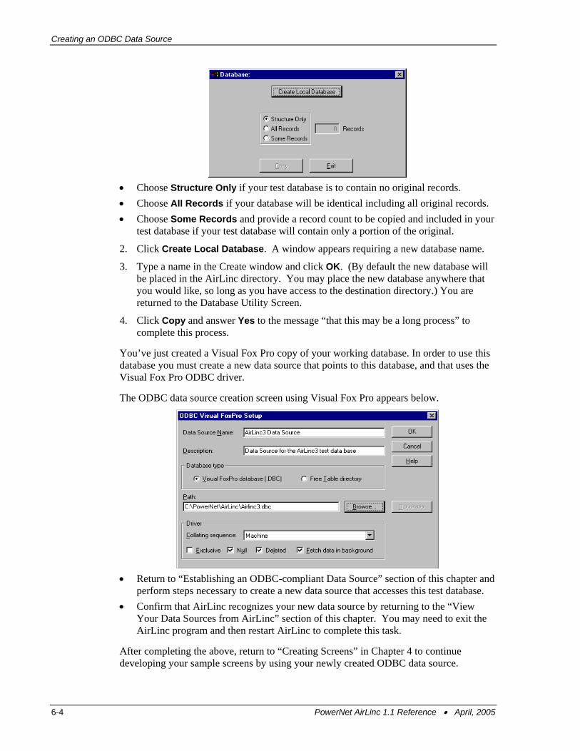
Creating an ODBC Data Source
• Choose Structure Only if your test database is to contain no original records. • Choose All Records if your database will be identical including all original records. • Choose Some Records and provide a record count to be copied and included in your
test database if your test database will contain only a portion of the original.
2. Click Create Local Database. A window appears requiring a new database name.
3. Type a name in the Create window and click OK. (By default the new database will be placed in the AirLinc directory. You may place the new database anywhere that you would like, so long as you have access to the destination directory.) You are returned to the Database Utility Screen.
4. Click Copy and answer Yes to the message “that this may be a long process” to complete this process.
You’ve just created a Visual Fox Pro copy of your working database. In order to use this database you must create a new data source that points to this database, and that uses the Visual Fox Pro ODBC driver.
The ODBC data source creation screen using Visual Fox Pro appears below.
• Return to “Establishing an ODBC-compliant Data Source” section of this chapter and
perform steps necessary to create a new data source that accesses this test database. • Confirm that AirLinc recognizes your new data source by returning to the “View
Your Data Sources from AirLinc” section of this chapter. You may need to exit the AirLinc program and then restart AirLinc to complete this task.
After completing the above, return to “Creating Screens” in Chapter 4 to continue developing your sample screens by using your newly created ODBC data source.
6-4 PowerNet AirLinc 1.1 Reference • April, 2005
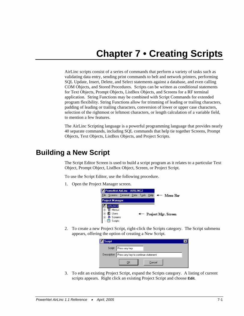
Chapter 7 • Creating Scripts AirLinc scripts consist of a series of commands that perform a variety of tasks such as validating data entry, sending print commands to belt and network printers, performing SQL Update, Insert, Delete, and Select statements against a database, and even calling COM Objects, and Stored Procedures. Scripts can be written as conditional statements for Text Objects, Prompt Objects, ListBox Objects, and Screens for a RF terminal application. String Functions may be combined with Script Commands for extended program flexibility. String Functions allow for trimming of leading or trailing characters, padding of leading or trailing characters, conversion of lower or upper case characters, selection of the rightmost or leftmost characters, or length calculation of a variable field, to mention a few features.
The AirLinc Scripting language is a powerful programming language that provides nearly 40 separate commands, including SQL commands that help tie together Screens, Prompt Objects, Text Objects, ListBox Objects, and Project Scripts.
Building a New Script The Script Editor Screen is used to build a script program as it relates to a particular Text Object, Prompt Object, ListBox Object, Screen, or Project Script.
To use the Script Editor, use the following procedure.
1. Open the Project Manager screen.
2. To create a new Project Script, right-click the Scripts category. The Script submenu
appears, offering the option of creating a New Script.
3. To edit an existing Project Script, expand the Scripts category. A listing of current
scripts appears. Right click an existing Project Script and choose Edit.
PowerNet AirLinc 1.1 Reference • April, 2005 7-1
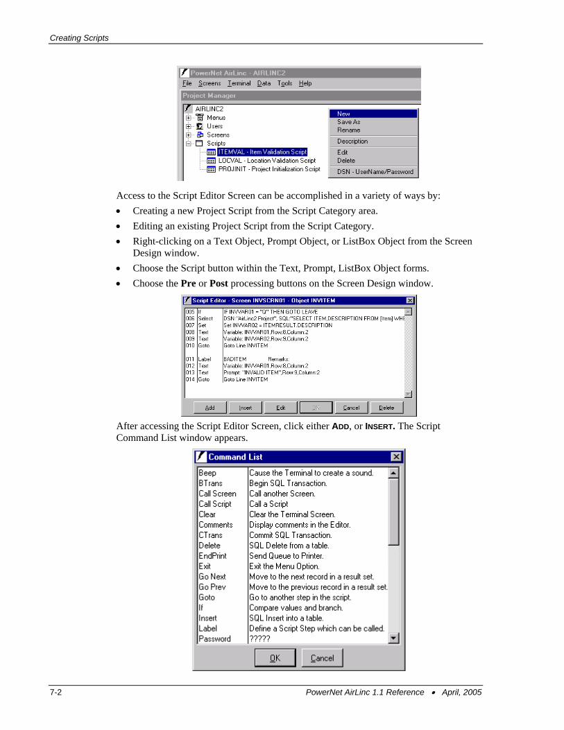
Creating Scripts
Access to the Script Editor Screen can be accomplished in a variety of ways by: • Creating a new Project Script from the Script Category area. • Editing an existing Project Script from the Script Category. • Right-clicking on a Text Object, Prompt Object, or ListBox Object from the Screen
Design window. • Choose the Script button within the Text, Prompt, ListBox Object forms. • Choose the Pre or Post processing buttons on the Screen Design window.
After accessing the Script Editor Screen, click either ADD, or INSERT. The Script Command List window appears.
7-2 PowerNet AirLinc 1.1 Reference • April, 2005
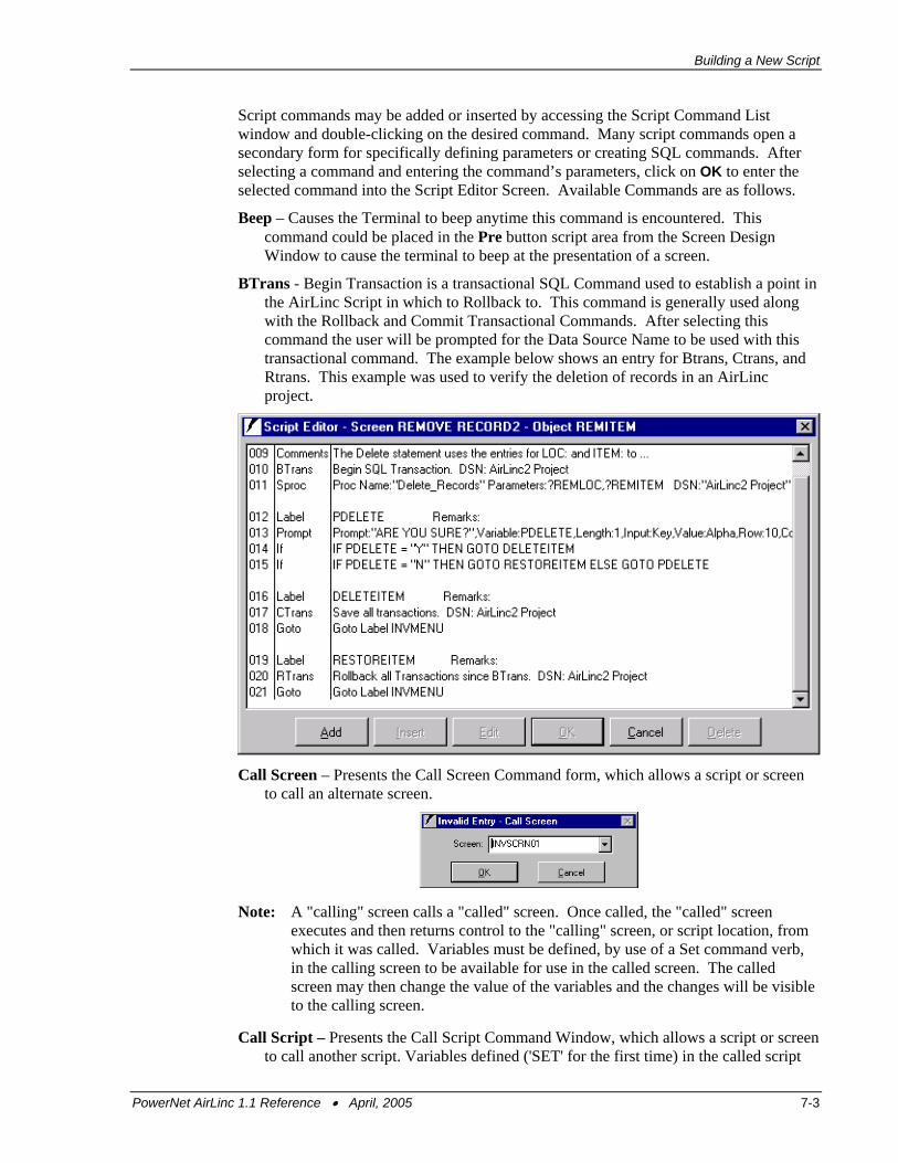
Building a New Script
Script commands may be added or inserted by accessing the Script Command List window and double-clicking on the desired command. Many script commands open a secondary form for specifically defining parameters or creating SQL commands. After selecting a command and entering the command’s parameters, click on OK to enter the selected command into the Script Editor Screen. Available Commands are as follows.
Beep – Causes the Terminal to beep anytime this command is encountered. This command could be placed in the Pre button script area from the Screen Design Window to cause the terminal to beep at the presentation of a screen.
BTrans - Begin Transaction is a transactional SQL Command used to establish a point in the AirLinc Script in which to Rollback to. This command is generally used along with the Rollback and Commit Transactional Commands. After selecting this command the user will be prompted for the Data Source Name to be used with this transactional command. The example below shows an entry for Btrans, Ctrans, and Rtrans. This example was used to verify the deletion of records in an AirLinc project.
Call Screen – Presents the Call Screen Command form, which allows a script or screen
to call an alternate screen.
Note: A "calling" screen calls a "called" screen. Once called, the "called" screen executes and then returns control to the "calling" screen, or script location, from which it was called. Variables must be defined, by use of a Set command verb, in the calling screen to be available for use in the called screen. The called screen may then change the value of the variables and the changes will be visible to the calling screen.
Call Script – Presents the Call Script Command Window, which allows a script or screen to call another script. Variables defined ('SET' for the first time) in the called script
PowerNet AirLinc 1.1 Reference • April, 2005 7-3
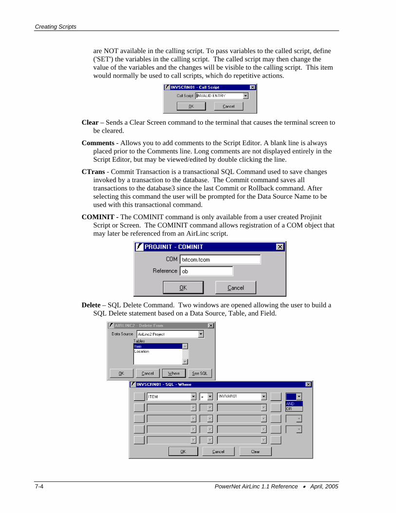
Creating Scripts
are NOT available in the calling script. To pass variables to the called script, define ('SET') the variables in the calling script. The called script may then change the value of the variables and the changes will be visible to the calling script. This item would normally be used to call scripts, which do repetitive actions.
Clear – Sends a Clear Screen command to the terminal that causes the terminal screen to be cleared.
Comments - Allows you to add comments to the Script Editor. A blank line is always placed prior to the Comments line. Long comments are not displayed entirely in the Script Editor, but may be viewed/edited by double clicking the line.
CTrans - Commit Transaction is a transactional SQL Command used to save changes invoked by a transaction to the database. The Commit command saves all transactions to the database3 since the last Commit or Rollback command. After selecting this command the user will be prompted for the Data Source Name to be used with this transactional command.
COMINIT - The COMINIT command is only available from a user created Projinit Script or Screen. The COMINIT command allows registration of a COM object that may later be referenced from an AirLinc script.
Delete – SQL Delete Command. Two windows are opened allowing the user to build a
SQL Delete statement based on a Data Source, Table, and Field.
7-4 PowerNet AirLinc 1.1 Reference • April, 2005
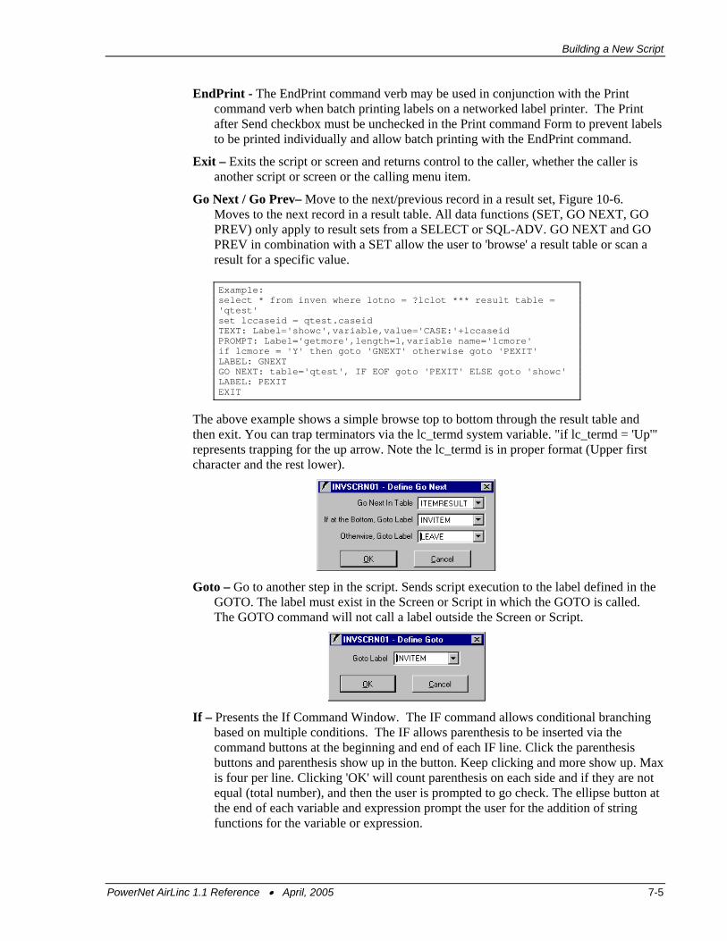
Building a New Script
EndPrint - The EndPrint command verb may be used in conjunction with the Print command verb when batch printing labels on a networked label printer. The Print after Send checkbox must be unchecked in the Print command Form to prevent labels to be printed individually and allow batch printing with the EndPrint command.
Exit – Exits the script or screen and returns control to the caller, whether the caller is another script or screen or the calling menu item.
Go Next / Go Prev– Move to the next/previous record in a result set, Figure 10-6. Moves to the next record in a result table. All data functions (SET, GO NEXT, GO PREV) only apply to result sets from a SELECT or SQL-ADV. GO NEXT and GO PREV in combination with a SET allow the user to 'browse' a result table or scan a result for a specific value. Example: select * from inven where lotno = ?lclot *** result table = 'qtest' set lccaseid = qtest.caseid TEXT: Label='showc',variable,value='CASE:'+lccaseid PROMPT: Label='getmore',length=1,variable name='lcmore' if lcmore = 'Y' then goto 'GNEXT' otherwise goto 'PEXIT' LABEL: GNEXT GO NEXT: table='qtest', IF EOF goto 'PEXIT' ELSE goto 'showc' LABEL: PEXIT EXIT
The above example shows a simple browse top to bottom through the result table and then exit. You can trap terminators via the lc_termd system variable. "if lc_termd = 'Up'" represents trapping for the up arrow. Note the lc_termd is in proper format (Upper first character and the rest lower).
Goto – Go to another step in the script. Sends script execution to the label defined in the GOTO. The label must exist in the Screen or Script in which the GOTO is called. The GOTO command will not call a label outside the Screen or Script.
If – Presents the If Command Window. The IF command allows conditional branching based on multiple conditions. The IF allows parenthesis to be inserted via the command buttons at the beginning and end of each IF line. Click the parenthesis buttons and parenthesis show up in the button. Keep clicking and more show up. Max is four per line. Clicking 'OK' will count parenthesis on each side and if they are not equal (total number), and then the user is prompted to go check. The ellipse button at the end of each variable and expression prompt the user for the addition of string functions for the variable or expression.
PowerNet AirLinc 1.1 Reference • April, 2005 7-5
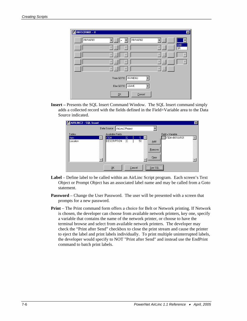
Creating Scripts
Insert – Presents the SQL Insert Command Window. The SQL Insert command simply adds a collected record with the fields defined in the Field=Variable area to the Data Source indicated.
Label – Define label to be called within an AirLinc Script program. Each screen’s Text Object or Prompt Object has an associated label name and may be called from a Goto statement.
Password – Change the User Password. The user will be presented with a screen that prompts for a new password.
Print – The Print command form offers a choice for Belt or Network printing. If Network is chosen, the developer can choose from available network printers, key one, specify a variable that contains the name of the network printer, or choose to have the terminal browse and select from available network printers. The developer may check the “Print after Send” checkbox to close the print stream and cause the printer to eject the label and print labels individually. To print multiple uninterrupted labels, the developer would specify to NOT "Print after Send" and instead use the EndPrint command to batch print labels.
7-6 PowerNet AirLinc 1.1 Reference • April, 2005
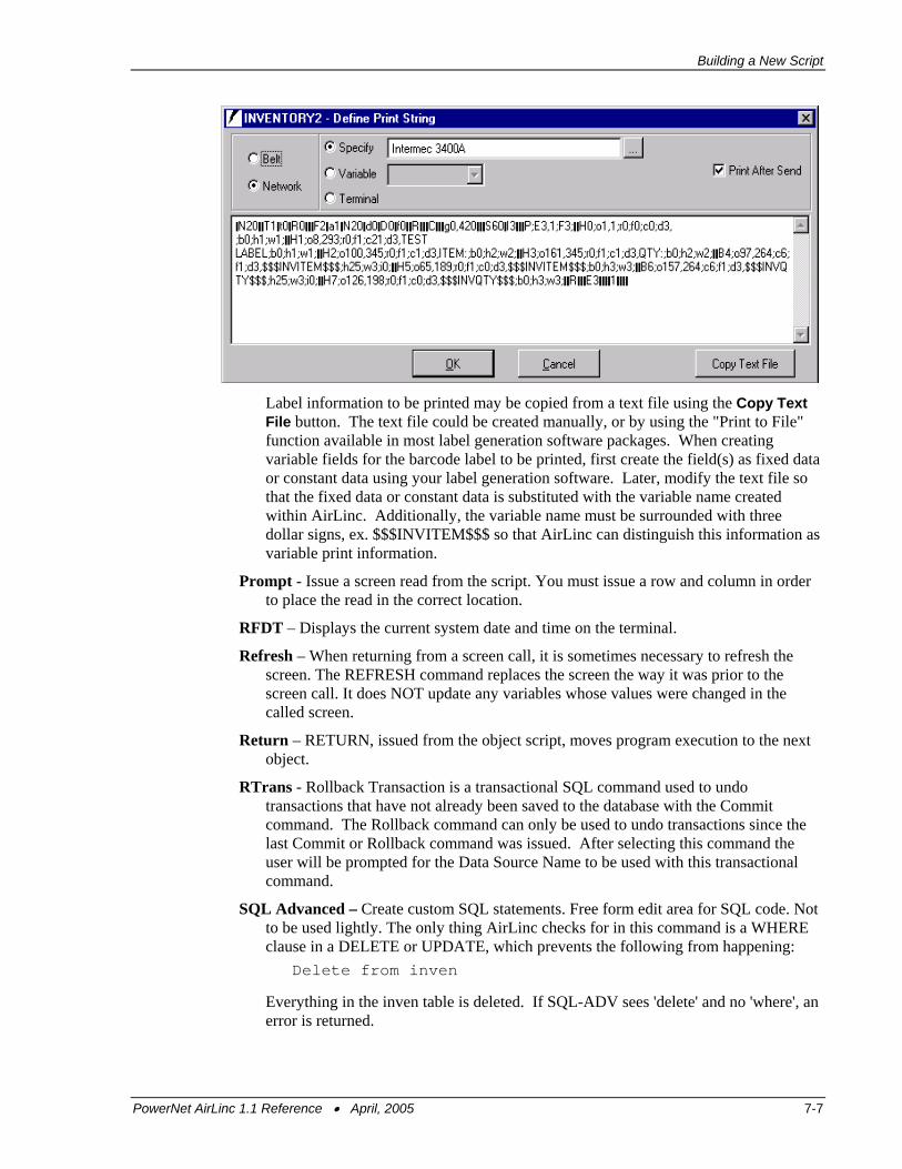
Building a New Script
Label information to be printed may be copied from a text file using the Copy Text File button. The text file could be created manually, or by using the "Print to File" function available in most label generation software packages. When creating variable fields for the barcode label to be printed, first create the field(s) as fixed data or constant data using your label generation software. Later, modify the text file so that the fixed data or constant data is substituted with the variable name created within AirLinc. Additionally, the variable name must be surrounded with three dollar signs, ex. $$$INVITEM$$$ so that AirLinc can distinguish this information as variable print information.
Prompt - Issue a screen read from the script. You must issue a row and column in order to place the read in the correct location.
RFDT – Displays the current system date and time on the terminal.
Refresh – When returning from a screen call, it is sometimes necessary to refresh the screen. The REFRESH command replaces the screen the way it was prior to the screen call. It does NOT update any variables whose values were changed in the called screen.
Return – RETURN, issued from the object script, moves program execution to the next object.
RTrans - Rollback Transaction is a transactional SQL command used to undo transactions that have not already been saved to the database with the Commit command. The Rollback command can only be used to undo transactions since the last Commit or Rollback command was issued. After selecting this command the user will be prompted for the Data Source Name to be used with this transactional command.
SQL Advanced – Create custom SQL statements. Free form edit area for SQL code. Not to be used lightly. The only thing AirLinc checks for in this command is a WHERE clause in a DELETE or UPDATE, which prevents the following from happening:
Delete from inven
Everything in the inven table is deleted. If SQL-ADV sees 'delete' and no 'where', an error is returned.
PowerNet AirLinc 1.1 Reference • April, 2005 7-7

Creating Scripts
Select – SQL Select Statement. Only available for single table searches. Multi-table joins must be performed with the ADV-SQL free form command.
SerClose - Serial Close command presents a form that prompts for port and error branching. Serial Close is used in conjunction with other Serial commands such as Serial Open, Serial Read, and Serial Write. SerClose will clear all buffers for that port.
SerOpen - Serial Open command opens a form that presents Prompts/Pulldowns for port, handshaking, baud, parity, databits, stopbits, and error branching. A Serial Open command must be issued to establish communications with a serial device. Ports cannot be opened more than once without closing during a screen/script. Serial Open is used in conjunction with other Serial commands such as Serial Close, Serial Read, and Serial Write.
SerRead - Serial Read command presents a form that prompts for port, terminator, timeout, length, return variable, and error branching. For serial read one must specify at least one read condition, wait on terminator, wait on timeout, or wait on length. One can specify one or more conditions to end the read. Terminator in the SerRead is a one-byte character and can be keyed either as a character (keyboard) or via the ASCII option to key a non-keyboard byte and is not included in the return variable. Developers must manage the return variable and clean up any unneeded characters; i.e. <cr><lf>. Serial Read is used in conjunction with other Serial commands such as Serial Close, Serial Open, and Serial Write.
SerWrite - Serial Write command presents a form that prompts for port, text or variable, and error branching. A Serial Write permits passing of information to a Serial device, such as a Serial Port / VT100 Terminal.
Note: Developer is responsible for port management when working with Serial commands. For all error branching, in the event of an error, an entry is placed in the AirLinc error log detailing the error, execution is passed to the error branch label and
7-8 PowerNet AirLinc 1.1 Reference • April, 2005
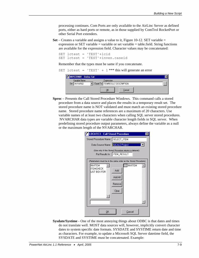
Building a New Script
processing continues. Com Ports are only available to the AirLinc Server as defined ports, either as hard ports or remote, as in those supplied by ComTrol RocketPort or other Serial Port extenders.
Set – Creates a variable and assigns a value to it, Figure 10-12. SET variable = expression or SET variable = variable or set variable = table.field. String functions are available for the expression field. Character values may be concatenated:
SET lctest = 'TEST'+lcid SET lctest = 'TEST'+inven.caseid
Remember that the types must be same if you concatenate.
SET lctest = 'TEST' + 1 *** this will generate an error
Sproc – Presents the Call Stored Procedure Windows. This command calls a stored procedure from a data source and places the results in a temporary result set. The stored procedure name is NOT validated and must match an existing stored procedure name. Stored procedure name references are a maximum of 20 characters. Use variable names of at least two characters when calling SQL server stored procedures. NVARCHAR data types are variable character length fields in SQL server. When predefining stored procedure output parameters, always define the variable as a null or the maximum length of the NVARCHAR.
Sysdate/Systime - One of the most annoying things about ODBC is that dates and times
do not translate well. MOST data sources will, however, implicitly convert character dates to system specific date formats. SYSDATE and SYSTIME return date and time as characters. For example, to update a Microsoft SQL Server datetime field, the SYSDATE and SYSTIME must be concatenated. Example:
PowerNet AirLinc 1.1 Reference • April, 2005 7-9
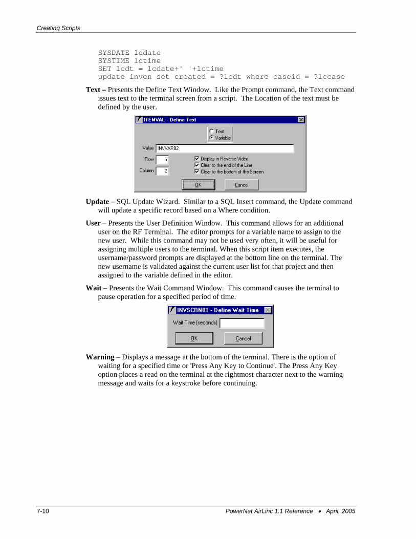
Creating Scripts
SYSDATE lcdate SYSTIME lctime SET lcdt = lcdate+' '+lctime update inven set created = ?lcdt where caseid = ?lccase
Text – Presents the Define Text Window. Like the Prompt command, the Text command issues text to the terminal screen from a script. The Location of the text must be defined by the user.
Update – SQL Update Wizard. Similar to a SQL Insert command, the Update command will update a specific record based on a Where condition.
User – Presents the User Definition Window. This command allows for an additional user on the RF Terminal. The editor prompts for a variable name to assign to the new user. While this command may not be used very often, it will be useful for assigning multiple users to the terminal. When this script item executes, the username/password prompts are displayed at the bottom line on the terminal. The new username is validated against the current user list for that project and then assigned to the variable defined in the editor.
Wait – Presents the Wait Command Window. This command causes the terminal to pause operation for a specified period of time.
Warning – Displays a message at the bottom of the terminal. There is the option of waiting for a specified time or 'Press Any Key to Continue'. The Press Any Key option places a read on the terminal at the rightmost character next to the warning message and waits for a keystroke before continuing.
7-10 PowerNet AirLinc 1.1 Reference • April, 2005
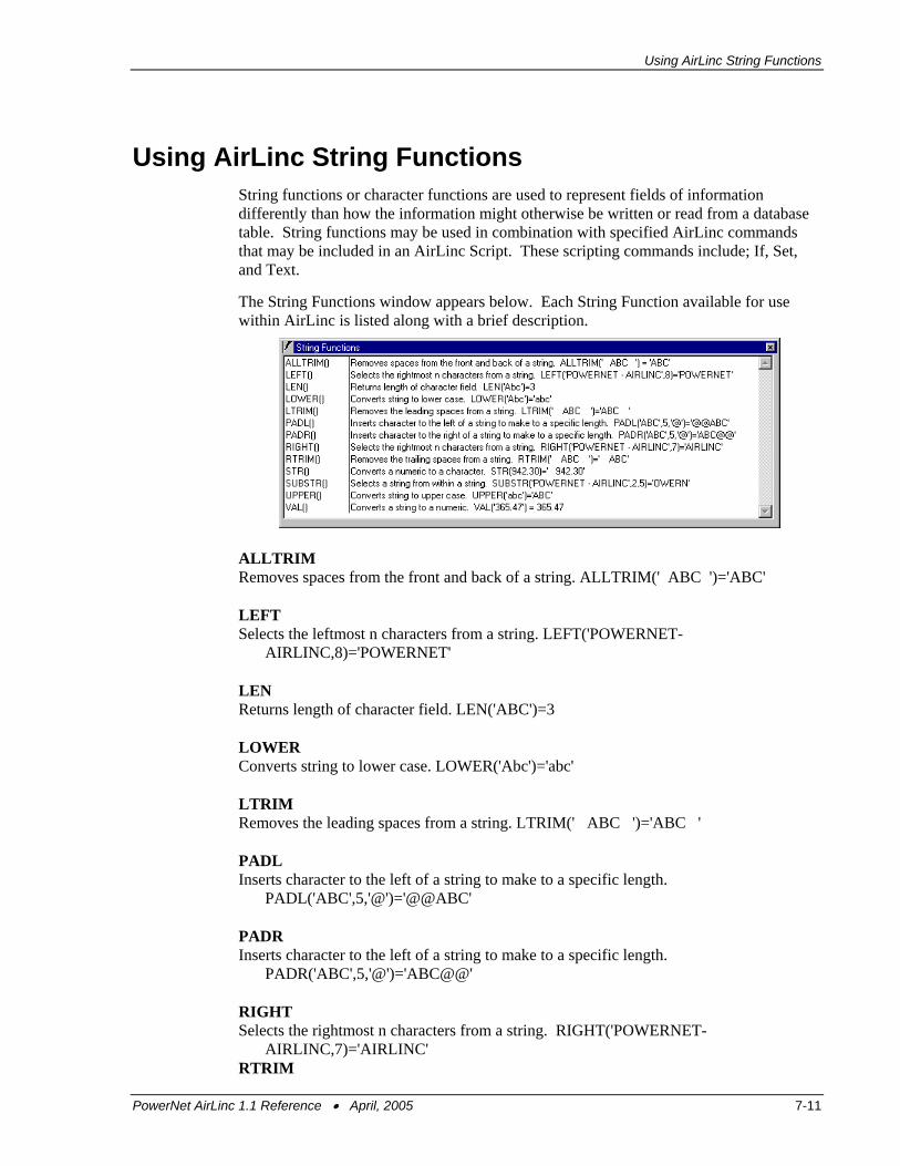
Using AirLinc String Functions
Using AirLinc String Functions String functions or character functions are used to represent fields of information differently than how the information might otherwise be written or read from a database table. String functions may be used in combination with specified AirLinc commands that may be included in an AirLinc Script. These scripting commands include; If, Set, and Text.
The String Functions window appears below. Each String Function available for use within AirLinc is listed along with a brief description.
ALLTRIM Removes spaces from the front and back of a string. ALLTRIM(' ABC ')='ABC' LEFT Selects the leftmost n characters from a string. LEFT('POWERNET-
AIRLINC,8)='POWERNET' LEN Returns length of character field. LEN('ABC')=3 LOWER Converts string to lower case. LOWER('Abc')='abc' LTRIM Removes the leading spaces from a string. LTRIM(' ABC ')='ABC ' PADL Inserts character to the left of a string to make to a specific length.
PADL('ABC',5,'@')='@@ABC' PADR Inserts character to the left of a string to make to a specific length.
PADR('ABC',5,'@')='ABC@@' RIGHT Selects the rightmost n characters from a string. RIGHT('POWERNET-
AIRLINC,7)='AIRLINC' RTRIM
PowerNet AirLinc 1.1 Reference • April, 2005 7-11

Creating Scripts
Removes the trailing spaces from a string. RTRIM(' ABC ')=' ABC' STR Converts a numeric to a character. STR(942.30)=' 942', STR(942.30,10,2)=' 942.30' SUBSTR Select a string from within a string. SUBSTR('POWERNET-AIRLINC',2,5)='OWERN' UPPER Converts string to upper case. UPPER('abc')='ABC' VAL Converts a string to a numeric. VAL('365.47')=365.47
When collecting information with an AirLinc project, all fields are treated as characters. If records are written to a database where certain fields must be treated as a numeric, it is then necessary to convert any required fields to a numeric value prior to writing a record to a database.
7-12 PowerNet AirLinc 1.1 Reference • April, 2005
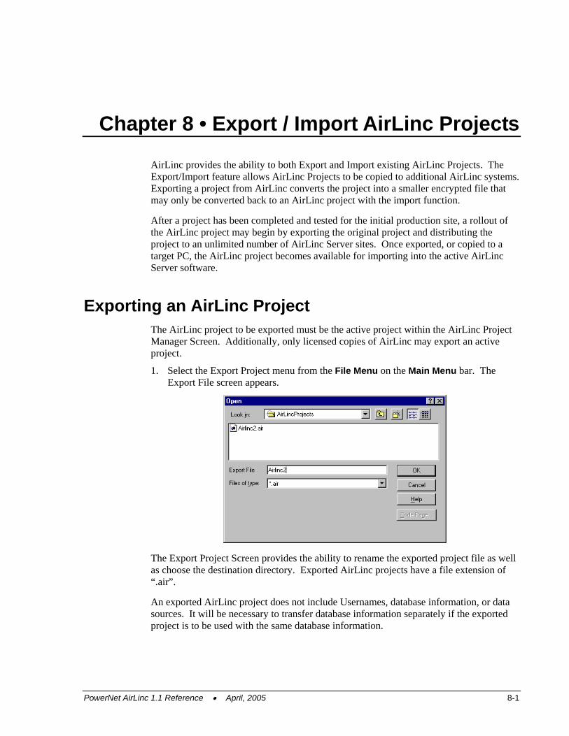
Chapter 8 • Export / Import AirLinc Projects
AirLinc provides the ability to both Export and Import existing AirLinc Projects. The Export/Import feature allows AirLinc Projects to be copied to additional AirLinc systems. Exporting a project from AirLinc converts the project into a smaller encrypted file that may only be converted back to an AirLinc project with the import function.
After a project has been completed and tested for the initial production site, a rollout of the AirLinc project may begin by exporting the original project and distributing the project to an unlimited number of AirLinc Server sites. Once exported, or copied to a target PC, the AirLinc project becomes available for importing into the active AirLinc Server software.
Exporting an AirLinc Project The AirLinc project to be exported must be the active project within the AirLinc Project Manager Screen. Additionally, only licensed copies of AirLinc may export an active project.
1. Select the Export Project menu from the File Menu on the Main Menu bar. The Export File screen appears.
The Export Project Screen provides the ability to rename the exported project file as well as choose the destination directory. Exported AirLinc projects have a file extension of “.air”.
An exported AirLinc project does not include Usernames, database information, or data sources. It will be necessary to transfer database information separately if the exported project is to be used with the same database information.
PowerNet AirLinc 1.1 Reference • April, 2005 8-1
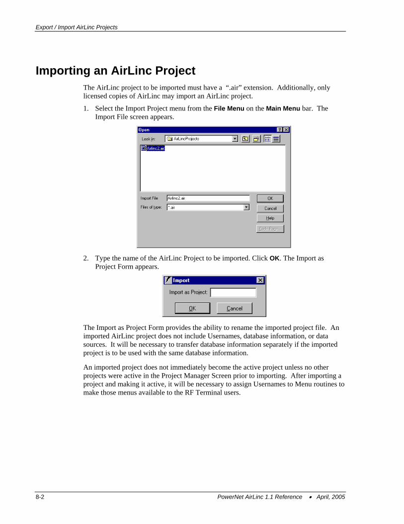
Export / Import AirLinc Projects
Importing an AirLinc Project The AirLinc project to be imported must have a “.air” extension. Additionally, only licensed copies of AirLinc may import an AirLinc project.
1. Select the Import Project menu from the File Menu on the Main Menu bar. The Import File screen appears.
2. Type the name of the AirLinc Project to be imported. Click OK. The Import as
Project Form appears.
The Import as Project Form provides the ability to rename the imported project file. An imported AirLinc project does not include Usernames, database information, or data sources. It will be necessary to transfer database information separately if the imported project is to be used with the same database information.
An imported project does not immediately become the active project unless no other projects were active in the Project Manager Screen prior to importing. After importing a project and making it active, it will be necessary to assign Usernames to Menu routines to make those menus available to the RF Terminal users.
8-2 PowerNet AirLinc 1.1 Reference • April, 2005
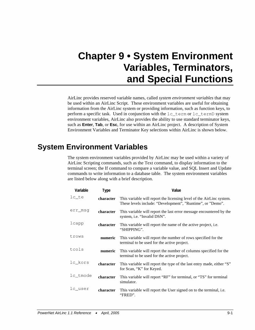
Chapter 9 • System Environment Variables, Terminators, and Special Functions
AirLinc provides reserved variable names, called system environment variables that may be used within an AirLinc Script. These environment variables are useful for obtaining information from the AirLinc system or providing information, such as function keys, to perform a specific task. Used in conjunction with the lc_term or lc_termD system environment variables, AirLinc also provides the ability to use standard terminator keys, such as Enter, Tab, or Esc, for use within an AirLinc project. A description of System Environment Variables and Terminator Key selections within AirLinc is shown below.
System Environment Variables The system environment variables provided by AirLinc may be used within a variety of AirLinc Scripting commands, such as the Text command, to display information to the terminal screen; the If command to compare a variable value, and SQL Insert and Update commands to write information to a database table. The system environment variables are listed below along with a brief description.
Variable Type Value lc_te character This variable will report the licensing level of the AirLinc system.
These levels include: “Development”, ”Runtime”, or ”Demo”. err_msg character This variable will report the last error message encountered by the
system, i.e. “Invalid DSN”. lcapp character This variable will report the name of the active project, i.e.
“SHIPPING”. trows numeric This variable will report the number of rows specified for the
terminal to be used for the active project. tcols numeric This variable will report the number of columns specified for the
terminal to be used for the active project. lc_kors character This variable will report the type of the last entry made, either “S”
for Scan, “K” for Keyed. lc_tmode character This variable will report “RF” for terminal, or “TS” for terminal
simulator. lc_user character This variable will report the User signed on to the terminal, i.e.
“FRED”.
PowerNet AirLinc 1.1 Reference • April, 2005 9-1
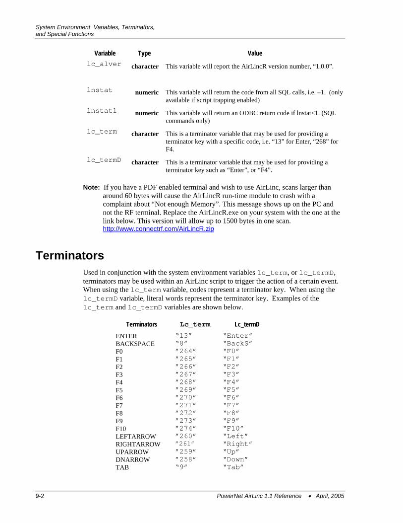
System Environment Variables, Terminators, and Special Functions
Variable Type Value lc_alver character This variable will report the AirLincR version number, “1.0.0”.
lnstat numeric This variable will return the code from all SQL calls, i.e. –1. (only
available if script trapping enabled) lnstat1 numeric This variable will return an ODBC return code if lnstat<1. (SQL
commands only) lc_term character This is a terminator variable that may be used for providing a
terminator key with a specific code, i.e. “13” for Enter, “268” for F4.
lc_termD character This is a terminator variable that may be used for providing a terminator key such as “Enter”, or “F4”.
Note: If you have a PDF enabled terminal and wish to use AirLinc, scans larger than around 60 bytes will cause the AirLincR run-time module to crash with a complaint about “Not enough Memory”. This message shows up on the PC and not the RF terminal. Replace the AirLincR.exe on your system with the one at the link below. This version will allow up to 1500 bytes in one scan. http://www.connectrf.com/AirLincR.zip
Terminators Used in conjunction with the system environment variables lc_term, or lc_termD, terminators may be used within an AirLinc script to trigger the action of a certain event. When using the lc_term variable, codes represent a terminator key. When using the lc_termD variable, literal words represent the terminator key. Examples of the lc_term and lc_termD variables are shown below.
Terminators Lc_term Lc_termD ENTER “13” “Enter” BACKSPACE “8” “BackS” F0 ”264” “F0” F1 ”265” “F1” F2 ”266” “F2” F3 ”267” “F3” F4 ”268” “F4” F5 ”269” “F5” F6 ”270” “F6” F7 ”271” “F7” F8 ”272” “F8” F9 ”273” “F9” F10 ”274” “F10” LEFTARROW ”260” “Left” RIGHTARROW ”261” “Right” UPARROW ”259” “Up” DNARROW ”258” “Down” TAB “9” “Tab”
9-2 PowerNet AirLinc 1.1 Reference • April, 2005
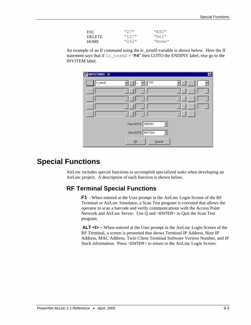
Special Functions
ESC “27” “ESC” DELETE “127” “Del” HOME “262” “Home”
An example of an If command using the lc_termD variable is shown below. Here the If statement says that if lc_termD = “F4” then GOTO the ENDINV label, else go to the INVITEM label.
Special Functions AirLinc includes special functions to accomplish specialized tasks when developing an AirLinc project. A description of each function is shown below.
RF Terminal Special Functions F1 - When entered at the User prompt in the AirLinc Login Screen of the RF Terminal or AirLinc Simulator, a Scan Test program is executed that allows the operator to scan a barcode and verify communications with the Access Point Network and AirLinc Server. Use Q and <ENTER> to Quit the Scan Test program.
ALT <I> - When entered at the User prompt in the AirLinc Login Screen of the RF Terminal, a screen is presented that shows Terminal IP Address, Host IP Address, MAC Address, Twin Client Terminal Software Version Number, and IP Stack information. Press <ENTER> to return to the AirLinc Login Screen.
PowerNet AirLinc 1.1 Reference • April, 2005 9-3
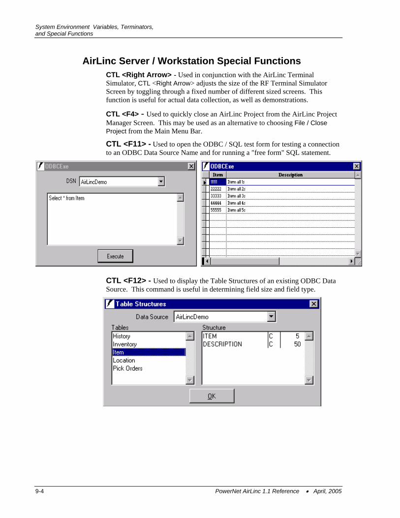
System Environment Variables, Terminators, and Special Functions
AirLinc Server / Workstation Special Functions CTL <Right Arrow> - Used in conjunction with the AirLinc Terminal Simulator, CTL <Right Arrow> adjusts the size of the RF Terminal Simulator Screen by toggling through a fixed number of different sized screens. This function is useful for actual data collection, as well as demonstrations.
CTL <F4> - Used to quickly close an AirLinc Project from the AirLinc Project Manager Screen. This may be used as an alternative to choosing File / Close Project from the Main Menu Bar.
CTL <F11> - Used to open the ODBC / SQL test form for testing a connection to an ODBC Data Source Name and for running a "free form" SQL statement.
CTL <F12> - Used to display the Table Structures of an existing ODBC Data Source. This command is useful in determining field size and field type.
9-4 PowerNet AirLinc 1.1 Reference • April, 2005
Special Functions
VT100 Interface Support
AirLinc Projects may be executed on Serial Port / VT100 terminals via the Start/Run or NT Startup command. The parameter syntax to use is the following: C:\PowerNet\AirLinc\AirLincR.exe "VT,12,5,1,38400,n,8,1" Where 12 is either 12 or 24 (24 - single high/single wide or 12 – double high/double wide).
5 is Serial Port Number 1 is Handshaking 38400 is Baud Rate n is Parity 8 is Bits 1 is Stop Bits.
Note: See the SerOpen command in Chapter 7 for available options. Communications
parameters must match the terminal. Q for quit is disabled. Once terminated (via error) must be restarted from AirLinc server. To execute AirLincR simulator on Windows machine one must execute AirLincR with parameter not equal to “VT”. RF mode is started without a parameter. Function keys are disabled in VT100 mode (however ctrl/A=F1, Ctrl/Z=F2).
PowerNet AirLinc 1.1 Reference • April, 2005 9-5