Embed Size (px)
Citation preview

8/3/2019 Airfuel Sensor
http://slidepdf.com/reader/full/airfuel-sensor 1/6
V
ehicle manufacturersface many challengeswhen producing auto-mobiles. One of thegreatest is balancingthe consumer’s desire
for high performance with the gov-
ernmen t’s mandate to keep th e airclean. The demands on engineers toreduce tailpipe emissions, increasefuel economy and improve engine
performance drive the creation of many new technologies.
Fuel and engine control manage-ment systems have evolved significant-ly over the years and are tasked withperforming that balancing act. Theoxygen sensor is one of the key engine
management system components. Theconventional zirconia dioxide O 2 sen-sor is widely used and responds tochanges in the exhaust content. It
switches from approximately 0 volts(lean) to 1.0 volt (rich) during normaloperation. It also provides feedback tothe powertrain control module (PCM)to maintain a close to stoichiometric(14.7:1) air/fuel ratio. This feedback isimportant to the three-way catalytic
converter, which needs the stoichio-metr ic ratio to operate efficiently.
The zirconia dioxide oxygen sensorhas remained basically unchanged for
40 December 2005
Air/fuel ratio sensors facilitate fuel controlthat is more precise than is possible with
conventional zirconia oxygen sensors.Interpreting signals from the newer sensors
requires a change in both tools and techniques.
Air/fuel ratio sensors facilitate fuel controlthat is more precise than is possible with
conventional zirconia oxygen sensors.Interpreting signals from the newer sensors
requires a change in both tools and techniques.
SUPERSNIFFERS:
WHY AIR/FUELRATIO SENSORS?
SUPERSNIFFERS:WHY AIR/FUELRATIO SENSORS?
B Y B OB P ATTENGALE

8/3/2019 Airfuel Sensor
http://slidepdf.com/reader/full/airfuel-sensor 2/6
nearly 30 years. But one change thatwas made was the addition of a sensorheater. The oxygen sensor needs atemperature of approximately 650°Fto operate properly. The heater is usedto reduce the time to closed-loop dur-ing cold-start conditions and to main-
tain closed-loop at idle during lowerexhaust temperatures.
Fuel control feedback using con-ventional zirconia dioxide O 2 sensors
is very narrow and constantly chang-ing. If a mixture other than stoi-chiometry is desired, the PCM willlikely go into open-loop operation. Toachieve greater fuel control manage-ment under any operating condition,the PCM needs to know the exact fuel
mixture at any given time. The next-generat ion O 2 sensors, primarilycalled air/fuel ratio sensors (A/F ratiosensors), are designed to achieve this
goal. Air/fuel ratio sensors allow forclosed-loop fuel control at mixturesother than stoichiometry.
Single-Cell & Dual-CellAir/Fuel SensorsAir/fuel ratio sensors may be referred to
as wide-range, wide-band, linear, lean,etc. There are two basic sensor de-signs—single-cell and dual-cell. Single-cell sensors generate voltage in a man-
P h o t o
c o u r t e s y
B o s c
h ; o t h e r p
h o t o s
& i l
l u s t r a t i o n s :
B o
b P a t t e n g a
l e
41December 2005

8/3/2019 Airfuel Sensor
http://slidepdf.com/reader/full/airfuel-sensor 3/6
ner similar to a conventional O 2 sensor.They’re used to control current flowthrough a specialized balanced con-trol/monitoring circuit within the PCM.
Toyota uses a single-cell linear A/Fratio sensor. The Toyota air/fuel sensorlooks similar to the conventional zirco-nia dioxide O 2 sensor; both have fourwires and the connectors look thesame. A zirconia sensor can be pluggedinto the A/F ratio sensor harness withminor modifications; however, the sys-tem will not work properly with an in-correct sensor.
Dual-cell sensors typically use the
planar design and are sometimes re-ferred to as current-pumping or ion- pumping sensors . They can be eitherwide-range or lean air/fuel ratio sensors.
Honda’s lean-burn engines use the leanA/F ratio sensor and can respond to ex-tremely lean mixtures—approximately22:1. Wide-range A/F ratio sensors havean effective air/fuel ratio range of ap-proximately 12:1 to 20:1. Both the sin-gle-cell and dual-cell sensors requirehigher te mperature s (approximately1200°F) to operate properly.
Single-cell linear air/fuel ratio sen-sors found on some California-certifiedToyota vehicles starting in 1996 cancause some confusion. The confusionis how the sensor is reported on anOBD II generic scan tool. Fig. 1
(above) is a photo of the screen of theOTC Genisys scan tool demonstratingthe B1 S1 O 2 sensor (the sensor para-meter is highlighted in blue). In order
to comply with the OBD II scan toolregulations, Toyota decided to reportthe air/fuel ratio sensor in a normalizedvoltage, 0 to 1.0 volt. The chart in Fig.2 explains how the normalized voltageworks. The Genisys scan tool showsthe voltage at .64 volt. This indicatesthe current air/fuel ratio is approxi-mately 14.4:1, or slightly rich. The en-hanced factory scan tool reports thelinear A/F ratio sensor as AF B1 S1,with a voltage ranging from 2.4 to 4.0volts. In this case, the voltage on thefactory scan tool would be 3.2 volts.
The confusion really begins when a
technician attempts to test the sensor. If you were not aware that this vehicle wasequipped with an air/fuel ratio sensor,you would follow conventional zirconia
42 December 2005
SUPERSNIFFERS: WHY AIR/FUEL RATIO SENSORS?
Fig. 1 Fig. 2
Fig. 3
8/3/2019 Airfuel Sensor
http://slidepdf.com/reader/full/airfuel-sensor 4/6
sensor testing procedures. You’d expectthe sensor to sweep up and down a
range of 0 to 1.0 volt. However, in thiscase, the sensor would remain steady atapproximately .66 volt. The next stepwould be to verify if the sensor can reg-ister a lean mixture below .2 volt and arich mixture above .8 volt. In this case,if you created a lean condition with avacuum leak, the voltage would increaseto approximately .8 volt, then return toapproximately .66 volt once the vacuum
leak was removed . You’d expect thevoltage to decrease to below .2 volt.Creating a rich condition using propanewould cause the voltage to decrease toapproximately .48 volt. Once again,you’d expect the voltage to increase toabove .8 volt.
At this point, most technicians mightthink the oxygen sensor or maybe eventhe PCM should be replaced. The Cali-fornia Air Resources Board (CARB)saw the potential issues this might cre-ate and approved a new OBD II gener-ic parameter for A/F ratio sensors. Toy-ota made the correction in later modelvehicles. On these vehicles, if yourOBD II generic scan tool does not in-clude the new OBD II generic parame-ters, the scan tool will not display a B1S1 value. Depending on the type of A/Fratio sensor used, the parameter may bedisplayed in amps or voltage.
Toyota recommends testing a linearair/fuel ratio sensor with the factory scantool. Fig. 3 (on page 42) shows severalcaptures from the Mastertech scan tool.
Using the A/F Control bidirectional test,the fuel mixture was commanded lean,then rich. The last line in the first screencapture shows the mixture being com-manded 12% lean. The AFS B1 S1 pa-rameter reads 3.92 volts, which indicatesa lean condition—approximately 18.4:1.The middle capture shows the mixturecommanded to 0%. The AFS B1 S1 pa-rameter returned to 3.43 volts—slightlylean, but close to stoichiometry. The fi-nal capture shows the mixture com-manded 25% rich. The AFS B1 S1shows 1.83 volts, which is off-the-chartrich. Based on this information, the A/Fratio sensor tested normal.
The air/fuel ratio sensor can be testedwithout the bidirectional control bymanually creating a rich/lean mixture
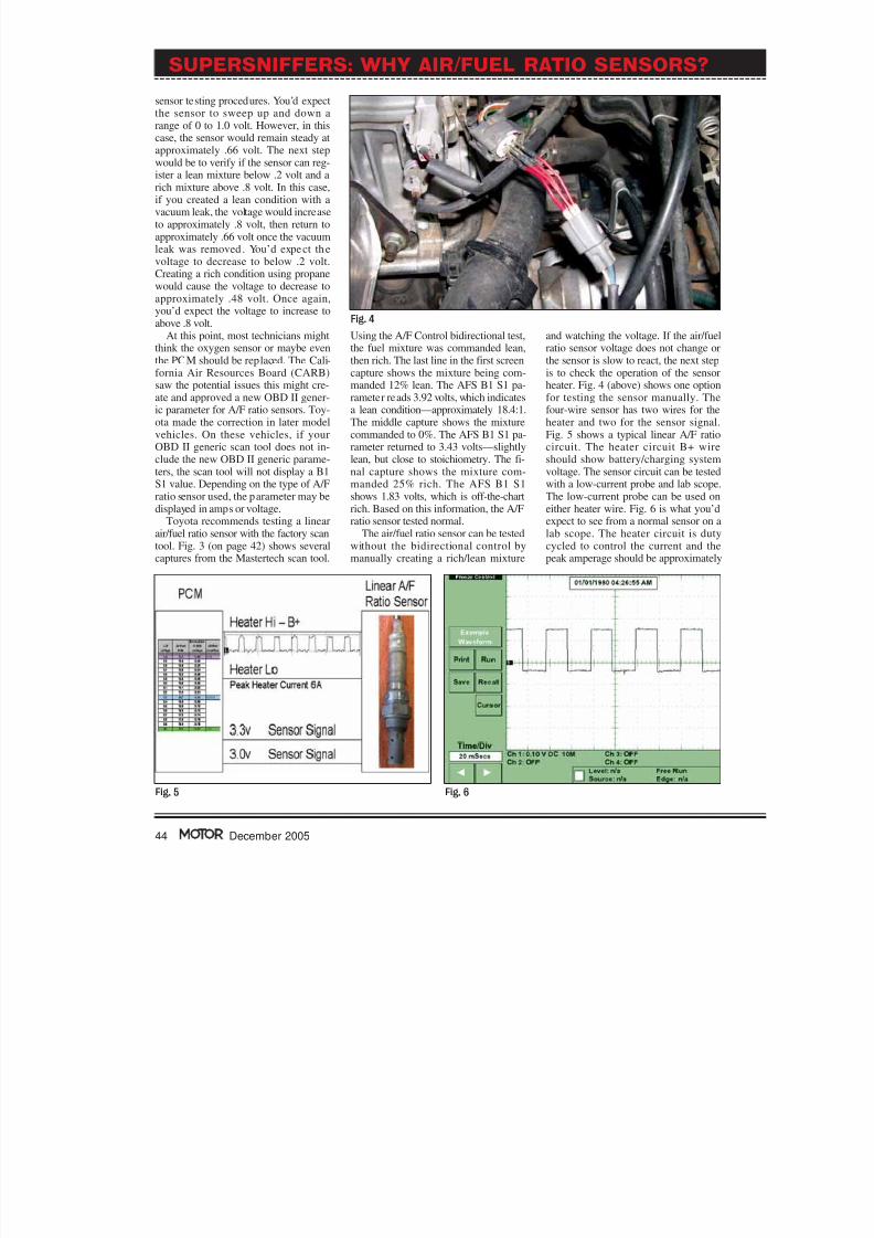
and watching the voltage. If the air/fuelratio sensor voltage does not change orthe sensor is slow to react, the next stepis to check the operation of the sensorheater. Fig. 4 (above) shows one optionfor testing the sensor manually. Thefour-wire sensor has two wires for theheater and two for the sensor signal.Fig. 5 shows a typical linear A/F ratiocircuit. The heater circuit B+ wireshould show battery/charging systemvoltage. The sensor circuit can be testedwith a low-current probe and lab scope.The low-current probe can be used oneither heater wire. Fig. 6 is what you’dexpect to see from a normal sensor on alab scope. The heater circuit is dutycycled to control the current and thepeak amperage should be approximately
44 December 2005
SUPERSNIFFERS: WHY AIR/FUEL RATIO SENSORS?
Fig. 5 Fig. 6
Fig. 4

8/3/2019 Airfuel Sensor
http://slidepdf.com/reader/full/airfuel-sensor 5/6
6 amps, depending on the application.There are several methods for check-
ing the sensor signal circuit. One in-volves using a voltmeter and checkingeach wire. One wire should have 3.0volts and the other 3.3 volts. If the volt-age at either wire is different from thosenumbers, check for open or shorted cir-cuits or possible PCM issues. A secondmethod involves disconnecting the sen-sor signal wires and measuring the volt-age across the sensor, while driving themixture rich, then lean. The sensor willfunction like a conventional O 2 sensor,ranging in voltage from 0 to 1.0 volt.Keep in mind that the heater circuitmust remain connected to maintain theproper sensor temperature. The thirdoption for checking the sensor signal
circuit requires connecting a DVOM inseries to one of the signal wires. Usingthe mA portion of the DVOM, watchthe current flow as you drive the fuelmixture rich, then lean. The currentflow should switch from positive to neg-ative as the mixture swings.
Fig. 7 shows DTC and freeze framedata from a 1998 Toyota Camry. Thevehicle had two recurring fault codes—DTC P0125 (Insufficient Coolant Tem-perature for Closed Loop Fuel Control)and P1135 (A/F Sensor Heater CircuitMalfunction, not displayed here). TheP1025 code is confusing due to themention of insufficient coolant temper-ature. This code has nothing to do withengine coolant temperature. The DTCwill set if the sensor output shows little
or no activity for 90 seconds. The fol-lowing conditions need to met for the
monitor to run: engine speed of 1500rpm or more, vehicle speed of 25 to 62mph, the TPS must not show idle, theseconditions must continue for at least 90seconds and the engine must run for atleast 140 seconds.
The P1135 code is the factory versionof P0125, and the diagnostic process issimilar. The most common cause is afaulty sensor. Fig. 8 shows 60 seconds of
a road test following sensor replace-ment, and demonstrates that the sensoris operating properly. A second optionfor verifying repair effectiveness is tocheck Mode 6 data. In this case, thecorrect conditions must be met for thetest to run. Then you’d need to check the Test Identification (TID) $07 Com-ponent Identification (CID) $01 follow-ing a road test.
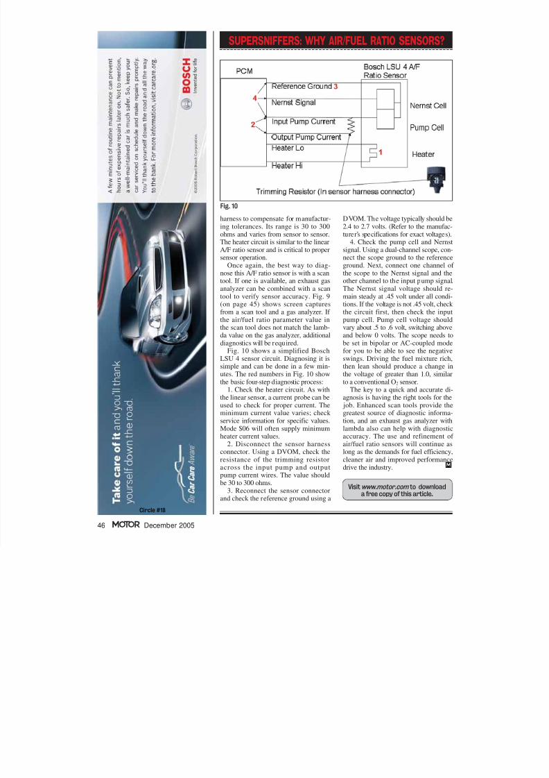
Current Pump SenorsThe Bosch LSU 4 is a wide-rangeair/fuel ratio sensor and is often re-ferred to as a current pump sensor . It’scomprised of two zirconia cells, withone of the cells acting as an input to thePCM. The pump cell acts as an ionpump, pumping oxygen ions from oneside of the sensor to the other. ThePCM monitors the Nernst signal lineand attempts to keep the voltage at .45volt. The PCM will increase and de-crease the current flow to the pump cellto maintain that voltage level. A trim-ming resistor is built into the sensor
45December 2005
Fig. 8 Fig. 9
Fig. 7
8/3/2019 Airfuel Sensor
http://slidepdf.com/reader/full/airfuel-sensor 6/6
harness to compensate for manufactur-ing tolerances. Its range is 30 to 300ohms and varies from sensor to sensor.The heater circuit is similar to the linearA/F ratio sensor and is critical to propersensor operation.
Once again, the best way to diag-nose this A/F ratio sensor is with a scantool. If one is available, an exhaust gasanalyzer can be combined with a scantool to verify sensor accuracy. Fig. 9(on page 45) shows screen capturesfrom a scan tool and a gas analyzer. If the air/fuel ratio parameter value inthe scan tool does not match the lamb-da value on the gas analyzer, additionaldiagnostics will be required.
Fig. 10 shows a simplified BoschLSU 4 sensor circuit. Diagnosing it issimple and can be done in a few min-utes. The red numbers in Fig. 10 showthe basic four-step diagnostic process:
1. Check the heater circuit. As withthe linear sensor, a current probe can beused to check for proper current. Theminimum current value varies; check service information for specific values.Mode $06 will often supply minimumheater current values.
2. Disconnect the sensor harnessconnector. Using a DVOM, check theresistance of the trimming resistoracross the input pump and output
pump current wires. The value shouldbe 30 to 300 ohms.3. Reconnect the sensor connector
and check the reference ground using a
DVOM. The voltage typically should be2.4 to 2.7 volts. (Refer to the manufac-turer’s specifications for exact voltages).
4. Check the pump cell and Nernstsignal. Using a dual-channel scope, con-nect the scope ground to the referenceground. Next, connect one channel of the scope to the Nernst signal and theother channel to the input pump signal.The Nernst signal voltage should re-main steady at .45 volt under all condi-tions. If the voltage is not .45 volt, check the circuit first, then check the inputpump cell. Pump cell voltage shouldvary about .5 to .6 volt, switching aboveand below 0 volts. The scope needs tobe set in bipolar or AC-coupled modefor you to be able to see the negativeswings. Driving the fuel mixture rich,then lean should produce a change inthe voltage of greater than 1.0, similarto a conventional O 2 sensor.
The key to a quick and accurate di-agnosis is having the right tools for the
job. Enhanced scan tools provide thegreatest source of diagnostic informa-tion, and an exhaust gas analyzer withlambda also can help with diagnosticaccuracy. The use and refinement of air/fuel ratio sensors will continue aslong as the demands for fuel efficiency,cleaner air and improved performancedrive the industry.
46 December 2005
SUPERSNIFFERS: WHY AIR/FUEL RATIO SENSORS?
Fig. 10
Visit www.motor.com to downloada free copy of this article.
Circle #18