Embed Size (px)
Citation preview

AIRFLOW™ INSTRUMENTS PROHOOD™
CAPTURE HOOD MODELS PH730/PH731
OWNER’S MANUAL
P/N 6005724, REVISION D
OCTOBER 2014
Model PH731 ProHood™ Model PH730 Micromanometer
Capture Hood (shown with standard and optional accessories)


i
LIMITATION OF WARRANTY AND LIABILITY
Copyright© TSI Incorporated / 2012-2014 / All rights reserved.
LIMITATION OF WARRANTY AND LIABILITY (effective April 2014)
(For country-specific terms and conditions outside of the USA, please visit www.tsi.com.)
Seller warrants the goods sold hereunder, excluding software, under normal use and service as described in the operator's manual, to be free from defects in workmanship and material for twenty-four (24) months, or if less, the length of time specified in the operator's manual, from the date of shipment to the customer. This warranty period is inclusive of any statutory warranty. This limited warranty is subject to the following exclusions and exceptions:
a. Hot-wire or hot-film sensors used with research anemometers, and certain other components when indicated in specifications, are warranted for 90 days from the date of shipment;
b. Pumps are warranted for one year or 3000 hours; whichever comes first;
c. Parts repaired or replaced as a result of repair services are warranted to be free from defects in workmanship and material, under normal use, for 90 days from the date of shipment;
d. Seller does not provide any warranty on finished goods manufactured by others or on any fuses, batteries or other consumable materials. Only the original manufacturer's warranty applies;
e. This warranty does not cover calibration requirements, and seller warrants only that the instrument or product is properly calibrated at the time of its manufacture. Instruments returned for calibration are not covered by this warranty;
f. This warranty is VOID if the instrument is opened by anyone other than a factory authorized service center with the one exception where requirements set forth in the manual allow an operator to replace consumables or perform recommended cleaning;
g. This warranty is VOID if the product has been misused, neglected, subjected to accidental or intentional damage, or is not properly installed, maintained, or cleaned according to the requirements of the manual. Unless specifically authorized in a separate writing by Seller, Seller makes no warranty with respect to, and shall have no liability in connection with, goods which are incorporated into other products or equipment, or which are modified by any person other than Seller.
The foregoing is IN LIEU OF all other warranties and is subject to the LIMITATIONS stated herein. NO OTHER
EXPRESS OR IMPLIED WARRANTY OF FITNESS FOR PARTICULAR PURPOSE OR MERCHANTABILITY IS
MADE. WITH RESPECT TO SELLER’S BREACH OF THE IMPLIED WARRANTY AGAINST INFRINGEMENT, SAID
WARRANTY IS LIMITED TO CLAIMS OF DIRECT INFRINGEMENT AND EXCLUDES CLAIMS OF CONTRIBUTORY
OR INDUCED INFRINGEMENTS. BUYER’S EXCLUSIVE REMEDY SHALL BE THE RETURN OF THE PURCHASE
PRICE DISCOUNTED FOR REASONABLE WEAR AND TEAR OR AT SELLER’S OPTION REPLACEMENT OF THE
GOODS WITH NON-INFRINGING GOODS.
TO THE EXTENT PERMITTED BY LAW, THE EXCLUSIVE REMEDY OF THE USER OR BUYER, AND THE LIMIT OF SELLER'S LIABILITY FOR ANY AND ALL LOSSES, INJURIES, OR DAMAGES CONCERNING THE GOODS (INCLUDING CLAIMS BASED ON CONTRACT, NEGLIGENCE, TORT, STRICT LIABILITY OR OTHERWISE) SHALL BE THE RETURN OF GOODS TO SELLER AND THE REFUND OF THE PURCHASE PRICE, OR, AT THE OPTION OF SELLER, THE REPAIR OR REPLACEMENT OF THE GOODS. IN THE CASE OF SOFTWARE, SELLER WILL REPAIR OR REPLACE DEFECTIVE SOFTWARE OR IF UNABLE TO DO SO, WILL REFUND THE PURCHASE PRICE OF THE SOFTWARE. IN NO EVENT SHALL SELLER BE LIABLE FOR LOST PROFITS, BUSINESS INTERRUPTION, OR ANY SPECIAL, DIRECT, CONSEQUENTIAL OR INCIDENTAL DAMAGES. SELLER SHALL NOT BE RESPONSIBLE FOR INSTALLATION, DISMANTLING OR REINSTALLATION COSTS OR CHARGES. No Action, regardless of form, may be brought against Seller more than 12 months after a cause of action has accrued. The goods returned under warranty to Seller's factory shall be at Buyer's risk of loss, and will be returned, if at all, at Seller's risk of loss.
Buyer and all users are deemed to have accepted this LIMITATION OF WARRANTY AND LIABILITY, which contains the complete and exclusive limited warranty of Seller. This LIMITATION OF WARRANTY AND LIABILITY may not be amended, modified or its terms waived, except by writing signed by an Officer of Seller.

ii
Service Policy
Knowing that inoperative or defective instruments are as detrimental to TSI as they are to our customers, our service policy is designed to give prompt attention to any problems. If any malfunction is discovered, please contact your nearest sales office or representative, or call Customer Service department at (800) 874-2811 (USA) or (1) 651-490-2811 (International).
Trademarks TSI
®, TSI logo, Airflow™ Instruments, LogDat-CH, are trademarks of TSI Incorporated.
.

iii
CONTENTS
About This Manual ...................................................................................................................................... v Formatting and Typography ................................................................................................................... v Technical Assistance—Help! .................................................................................................................. v
Chapter 1. Introduction .............................................................................................................................. 1 Instrument Description ............................................................................................................................ 2
Micromanometer .............................................................................................................................. 2 Micromanometer ..................................................................................................................................... 4 Standard Tools ....................................................................................................................................... 4
Pitot Tube ......................................................................................................................................... 4 Static Pressure Probe ...................................................................................................................... 4 ProHood Capture Hoods .................................................................................................................. 4
Optional Tools ........................................................................................................................................ 5 Velocity Matrix .................................................................................................................................. 5 Air Flow Probe .................................................................................................................................. 5 Temperature/Humidity Probe ........................................................................................................... 5 Thermoanemometer Probes ............................................................................................................ 5
Chapter 2. Unpacking and Setting Up ...................................................................................................... 7 Unpacking ............................................................................................................................................... 7 Preparing the Instrument for Use ........................................................................................................... 8
Power the Micromanometer with the AC Adapter............................................................................ 8 Power the Micromanometer with Batteries ...................................................................................... 8
Using the Pressure Ports...................................................................................................................... 10 Connecting a Pitot Tube ................................................................................................................ 11
Connecting the Static Pressure Port to the Micromanometer .............................................................. 11 Attaching the Micromanometer to the Capture Hood Base ................................................................. 12
Connecting the Velocity Matrix to the Micromanometer ................................................................ 13 Connecting the Air Flow Probe to the Micromanometer ...................................................................... 14 Connecting the Base Temperature Probe, Temperature and Humidity Probe or
Thermoanemometer Probe to the Micromanometer ..................................................................... 15 Using the Telescoping Thermoanemometer Probes or Temperature and Humidity Probe ................. 15
Extending the Probe....................................................................................................................... 15 Retracting the Probe ...................................................................................................................... 16
Chapter 3. Getting Started ....................................................................................................................... 17 Keypad Functions ................................................................................................................................. 17 Common Terms .................................................................................................................................... 18
Chapter 4. Menu Setup and Navigation .................................................................................................. 21 Menus ................................................................................................................................................... 21
Pressure Tool ................................................................................................................................. 21 Display Setup ................................................................................................................................. 23 Flow Setup [Pitot Tube, AF Probe (straight pitot tube) or Thermoanemometer Probe] ................ 24 Actual/Standard Setup ................................................................................................................... 25 Settings .......................................................................................................................................... 26 Data Logging .................................................................................................................................. 27 Bluetooth Functions ....................................................................................................................... 37 Applications .................................................................................................................................... 38 Calibration Factor (Cf) Selection .................................................................................................... 40 Calibration ...................................................................................................................................... 40
Printing Data Using the Portable Printer .............................................................................................. 41 LogDat-CH™ Downloading Software ................................................................................................... 41

iv
Chapter 5. Changing Capture Hoods ...................................................................................................... 43 Capture Hood Parts Identification ........................................................................................................ 43 Capture Hood Assembly ....................................................................................................................... 43
Alternate Hood Installation ............................................................................................................. 45 Direct Inflow Measurement Hood for Biological Safety Cabinets .................................................. 49
Chapter 6. Flow Measurements Using the Capture Hood .................................................................... 55 Single Reading Measurements ............................................................................................................ 55 Running Average Measurements ......................................................................................................... 56 Capture Hood Measurements (non-backpressure compensated) ....................................................... 56 Backpressure Compensated Measurements ....................................................................................... 56 “ERROR” Display ................................................................................................................................. 57
Chapter 7. Maintenance and Troubleshooting ....................................................................................... 59 Fabric Hood .......................................................................................................................................... 59 Micromanometer ................................................................................................................................... 59 Manifold ................................................................................................................................................ 59
Cases ............................................................................................................................................. 59 Calibration ............................................................................................................................................. 59
Appendix A. Back Pressure ..................................................................................................................... 61 Verifying Flow Measurements .............................................................................................................. 61
Appendix B. Traversing a Duct to Determine Average Air Velocity or Volume.................................. 63 Where to Take the Measurement ......................................................................................................... 63 Traversing a Round Duct...................................................................................................................... 64 Traversing a Square Duct..................................................................................................................... 65
Appendix C. Swirl X Flow Conditioner for Airflow Instruments Model PH731
ProHood Capture Hood ............................................................................................................................ 67 Description ............................................................................................................................................ 67 Performance Data ................................................................................................................................ 68 Installation and Usage .......................................................................................................................... 69

v
About This Manual
This manual explains how to set up, operate and maintain the Airflow Instruments PH730/PH731. Please
read it thoroughly before using the instrument.
Formatting and Typography
Step-by-step instructions are numbered in boldface type: 1, 2, 3, etc., set flush-left against the
margin.
References to keys on the micromanometer and the instrument's displayed readout are represented
by a typeface called Arial. In addition to the different typeface, displayed messages appear in quotes.
When reference is made to other sections of the manual, the section title is italicized.
Technical Assistance—Help!
For technical assistance or questions about the instrument, or if the instrument needs repair or
recalibration, call Customer Service at (800) 874-2811 (USA), or (1) 651-490-2811 (International).
Product application notes are available to provide more information on the product. These application
notes, as well as other related material, can be obtained by calling Customer Service or by visiting the
web site at www.tsi.com.

vi
(This page intentionally left blank)

1
Chapter 1. Introduction
The PH730/PH731 are lightweight and easy-to-use instruments packaged with a variety of accessories
for measuring pressure, temperature, humidity, air velocity, and air volume. Features of the
micromanometer include:
Single-function keys for ease of use
Auto-zero for pressure measurements, auto-density correction, and back-pressure compensation
when used with a capture hood
User-selectable English and metric units
Conversions between actual and standard flow
Discrete or continuous display and data logging capabilities
Output port for downloading to a printer or a PC
Bi-directional Bluetooth communications to 8934 printer or PC
Powered by AC adapter or batteries (rechargeable NiMH or alkaline)
Full field calibration
Designed for:
Test and balance professionals
Mechanical contractors
Industrial hygienists
Plant engineers and facilities maintenance personnel
Applications include:
Test, balance, or commission HVAC systems
Test clean rooms and biological safety cabinets
Measure fume hood or filter face velocity
Measure pressure, temperature, relative humidity, air velocity, or air flow
C A U T I O N WHILE USING THE PROHOOD CAPTURE HOOD TO TEST AIR FLOW IN DUCTS, YOU MAY
COME INTO CONTACT WITH OR BE EXPOSED TO DUST, POLLEN, MOLD, FUNGUS, OR
OTHER AIRBORNE CONTAMINANTS. IF YOU ARE OR MAY BE SENSITIVE TO DUST, POLLEN,
MOLD, FUNGUS, OR OTHER AIRBORNE CONTAMINANTS, ALWAYS USE AN APPROPRIATE
MASK OR RESPIRATOR WHILE EMPLOYING THE PROHOOD CAPTURE HOOD.

2 Airflow™ Instruments ProHood Capture Hoods PH730/PH731
Instrument Description
The basic PH730 includes a micromanometer, carrying case, 18 in. (46 cm) pitot tube, (2) static pressure
probes, (2) 8 ft (2.4 m) Norprene® tubing, user manual, LogDat-CH™ for Windows® data downloading
software and RS232 interface cable, neck strap, internal NiMH battery charger, (4) AA NiMH batteries,
AC adapter, and NIST traceable certificate.
The basic PH731 contains all of the PH730 components plus 2 ft 2 ft (610 mm 610 mm) air capture
hood, frame, and base. A variety of optional tools (see below) are also available to meet your
measurement needs.
The following paragraphs provide brief descriptions of the micromanometer and the various standard and
optional tools for use with the ProHood Capture Hood Refer to Chapters 3 and 4 for more detailed
information on using the micromanometer and taking measurements with various sensors and probes.
Micromanometer
Figures 1 and 2 show the features of the micromanometer used in the PH730/PH731.
Keypad
AC Adapter
Connection
Display
Headphone
Connection
USB PortProbe Connector
RS-232 Port
(factory use
only)
Figure 1: Features of the PH730/PH731 Micromanometer, Front View
®Norprene is a registered trademark of Norton Performance Plastics, Akron, Ohio, USA. ®Windows is a registered trademark of Microsoft Corporation.

Chapter 1: Introduction 3
Differential
Pressure Ports
Battery Compartment
Figure 2: Features of the PH730/PH731 Micromanometer, Back View
Figures 3 and 4 show the features of the ProHood Capture Hood.
Removable
Center Handle
Backpressure
Flap Actuator
Switch to pause a
reading or to
initiate
backpressure
compensation
Base Handle
Figure 3: Features of the ProHood Capture Hood Base, Side View

4 Airflow™ Instruments ProHood Capture Hoods PH730/PH731
Flow Manifold Backpressure Flap
Temperature
Sensor
Mount for Hood
Support Pole (4)
Figure 4: Features of the ProHood Capture Hood Base, Inside View
Micromanometer
The micromanometer is a multifunction instrument used to measure air velocity, air flow, absolute and
differential pressure, temperature, and humidity measurements when used with the tools listed below.
The lightweight micromanometer incorporates auto-zeroing for high-accuracy, low pressure
measurements. Measurements can be stored to memory for later recall or downloaded to a PC using the
LogDat-CH software and USB cable or with Bluetooth communications.
Standard Tools
This section gives a brief description of standard tools for the micromanometer.
Pitot Tube
The pitot tube is primarily used to obtain air velocity, air volume, and velocity pressure measurements
within ductwork. An 18 in. (46 cm) pitot tube is included with the PH730 or PH731 kits. Alternate sizes are
available.
Static Pressure Probe
The static pressure probe is primarily used to obtain static pressure measurements within ductwork.
Differential pressure measurements across a filter or coil can also be performed by placing one probe
upstream and the other downstream of the filter or coil.
ProHood Capture Hoods
Capture hoods are used to obtain volumetric air flow measurements through diffusers, registers and
grilles. Capture hoods are available in a kit with one 2 ft 2 ft (610 mm 610 mm) fabric hood, frame,
and base assembly. Alternate hood sizes are available. Descriptions and part numbers can be found in
Table 2 of Chapter 2 of this manual.

Chapter 1: Introduction 5
Optional Tools
This section gives a brief description of optional tools for the micromanometer.
Velocity Matrix
The velocity matrix is used to obtain area-averaged multi-point air velocity measurements useful in
laboratory hood face velocity testing, filter face velocity testing, and other applications such as kitchen
exhaust.
Air Flow Probe
The air flow probe model 800187 is an 18” (46 cm) straight pitot tube used to obtain single point air velocity or air volume measurements in ductwork.
Temperature/Humidity Probe
The temperature/humidity probe is used to obtain temperature measurements over the range of 14 to
140°F (-10 to 60°C), humidity measurements over the range of 5 to 95% RH, along with calculated wet
bulb temperature of 40 to 140°F (4 to 60°C) and dewpoint temperature of 5 to 120°F (-15 to 49°C).
Thermoanemometer Probes
Thermoanemometer probes can be used to measure air temperature, air velocities or air volume
measurements in ductwork as well as lower velocity applications such as face velocity measurements of
chemical fume hoods, biological safety cabinets and filtration systems. Four models are available in
straight or articulating construction, and with or without a relative humidity sensor. Models with a relative
humidity sensor can also calculate wet bulb and dewpoint temperature.
Thermoanemometer Probes
Model Description
960 Air Velocity and Temperature, Straight Probe
962 Air Velocity and Temperature, Articulating Probe
964 Air Velocity, Temperature, and Humidity, Straight Probe
966 Air Velocity, Temperature, and Humidity, Articulating Probe

6 Airflow™ Instruments ProHood Capture Hoods PH730/PH731
(This page intentionally left blank)

7
Chapter 2. Unpacking and Setting Up
This chapter describes unpacking and setting up (preparing) the ProHood capture hood and
micromanometer kit.
Unpacking
As you unpack the instrument and accessories, check the components against your packing list. If any
parts are missing or damaged, notify us immediately. Tables 1 and 2 list available standard and optional
components.
Table 1: List of Standard and Optional Components
Item Part No.
Models PH730 and PH731 Electronic Balancing Tools (Airflow Instruments)
PH730
PH731
Carrying case, PH730 1319378
Carrying case, wheeled hood kit, PH731 1319379
AA-size NiMH battery, four required 1208048
Two battery holders for four AA batteries 1801157
AC adapter 2182003
CONN AC EURO/IEC320 1302014
CONN AC AUST/IEC320 1302025
CONN AC UK/IEC320 1302015
Carry strap-tether 2913011
18” (46 cm) pitot probe 534534001
Two static pressure probes 3002017
16 ft (4.8 m) Neoprene tubing 3900031
Swirl X Flow Conditioner 801213
LogDat-CH software 7002328
USB cable 1303754
Operation and Service Manual 6005724
Calibration certificate N/A
Velocity Matrix Add On Kit 801090
Air Flow Probe - 18” (46 cm) straight pitot probe 800187
Temperature and Humidity Probe 800220
Air Velocity and Temperature, Straight Probe 960
Air Velocity and Temperature, Articulating Probe 962
Air Velocity, Temperature, and Humidity, Straight Probe 964
Air Velocity, Temperature, and Humidity, Articulating Probe 966
Wireless Bluetooth printer 8934

8 Airflow™ Instruments ProHood Capture Hoods PH730/PH731
Table 2: List of Optional Hood and Frame Kits
Item Part No.
1 ft 4 ft (305 mm 1220 mm) fabric hood and frame kit 801200
2 ft 4 ft (610 mm 1220 mm) fabric hood and frame kit 801201
1 ft 5 ft (305 mm 1525 mm) fabric hood and frame kit 801202
3 ft 3 ft (915 mm 915 mm) fabric hood and frame kit 801203
16 in. 16 in. (406 mm 406 mm) fabric hood and frame kit 801209
5.25 in. 4 ft (133 mm 1220 mm) fabric hood and frame kit 801210
28 in. 28 in. (710 mm 710 mm) fabric hood and frame kit 801211
28 in. 50 in. (710 mm 1270 mm) fabric hood and frame kit 801212
1 ft 4 ft (305 mm 1220 mm) and 2 ft 4 ft (610 mm 1220 mm) fabric hood
and frame kit
801206
1 ft 5 ft (305 mm 1525 mm) and 3 ft 3 ft (915 mm 915 mm) fabric hood
and frame kit
801207
8 in. 22 in. (205 mm 560 mm) BSC fabric hood, frame, poles, and stand kit 801204
10 in. 22 in. (255 mm 560 mm) BSC fabric hood, frame, poles, and stand kit 801205
The BSC hood kits are used to certify Class II bio-safety cabinets by taking direct in-flow measurements for NSF compliance.
Please complete the registration card included with this product and mail it promptly. The card allows us
to inform you of product updates. If you prefer, register through the TSI web site.
Preparing the Instrument for Use
Before you can use the Electronic Balancing Tool, you must decide on a power source.
Power the Micromanometer with the AC Adapter
The AC adapter can be used to power the instrument or to charge the NiMH batteries when the DIP
switch in the battery compartment is set to NiMH. If the DIP switch is set to Alkaline, and the AC power
adapter is connected then the batteries will be bypassed and the meter will be powered by the AC
adapter. Be sure to provide the correct voltage and frequency, which is marked on the back of the AC
adapter.
Power the Micromanometer with Batteries
The micromanometer is designed to operate with either alkaline or NiMH rechargeable batteries. Battery
life will be shorter if NiMH batteries are used. For your convenience, four NiMH batteries are included with
the instrument. If NiMH batteries are used the DIP switch will need to be changed. Refer to the next
section on setting the battery selection switch.
Note
The four NiMH batteries included with the instrument will need to be charged prior to use. Charge
time is 4 hours.
Carbon-zinc batteries are not recommended due to the danger of battery acid leakage.

Chapter 2: Unpacking and Setting Up 9
To select the type of batteries you are using:
1. Turn the unit off and locate the battery cover on the back of the micromanometer (see Figure 5).
Figure 5: Battery Cover Removal
2. Press down on the compartment cover and slide it down. (The cover slides off.)
3. Remove the battery holder by pulling up on the bottom (to loosen it) and then pulling the battery
holder free.
4. Refer to Figure 6 and set the battery selection switch to indicate the type of batteries you are using.
Battery Selection Switch
Figure 6: Location of Battery Type Selector Switch
5. Reinstall the battery holder and replace the battery compartment cover.

10 Airflow™ Instruments ProHood Capture Hoods PH730/PH731
To install replacement batteries:
1. Turn the unit off and locate the battery cover on the back of the micromanometer (see Figure 5).
2. Press down on the compartment cover and slide it down. (The cover slides off.)
3. Remove the battery holder by pulling up on the bottom (to loosen it) and then remove the battery
holder.
4. Remove the old batteries and replace with fresh batteries (alkaline or rechargeable NiMH). Make
certain batteries are correctly oriented.
5. Verify the battery selection switch is correctly set (see Figure 5).
6. Reinstall the battery holder and replace the compartment cover.
Note
Make sure the battery holder is oriented so that its terminals make contact with the spring contacts in
the battery compartment.
If fresh, new alkaline batteries are used, the battery indicator will show four (4) bars when first turned
on. With NiMH batteries, the indicator may show a lower value even when they are fully charged.
C A U T I O N
The percent power remaining will not be accurate for NiMH batteries because their voltage does not
decrease linearly with power use.
Due to the danger of battery leakage, remove batteries from the battery compartment before storage.
Never mix battery types.
The NiMH batteries should only be charged at room temperature. Starting with batteries that are too
cold or too warm can cause the charge cycle to stop early.
Using the Pressure Ports
The differential pressure ports are used to connect the micromanometer to various pressure based tools
including the ProHood Capture hood, Pitot tubes, Air Flow probe (straight pitot probe), Velocity Matrix and
static pressure probes. Tubing is used to connect the ports on the micromanometer to the probes.
Positive (+)
Pressure Port
Negative (–)
Pressure Port
Figure 7. Pressure Ports

Chapter 2: Unpacking and Setting Up 11
Connecting a Pitot Tube
When the micromanometer is connected to a pitot tube, air velocity or air volume measurements can be
taken. The pitot tube is connected to the (+) and (–) pressure ports on the micromanometer using two
pieces of tubing of equal length. The total pressure port of the probe connects to the (+) port on the
meter, and the static pressure port of the probe connects to the (–) port on the meter.
Total Pressure
Port (+)Static Pressure
Port (–)
Figure 8: Pitot Tube
Note
The pitot velocity needs a valid temperature to perform the standard or actual velocity correction. This
is accomplished in the “Actual/Std Setup” menu. If no probe capable of measuring temperature (plug
in probe) is connected, the“Temp Source” must be set to “Entered”. The duct air temperature must
then be manually inputted by the user using the “Entered Temp”setting. If the “Temp Source” is set to
Probe, and no probe is connected, dashes (------) will appear on the display.
For more information on entering the temperature manually, refer to the Actual/Standard Setup
section of this manual.
C A U T I O N Do not use the instrument or probes near hazardous voltage sources since
serious injury could result.
Connecting the Static Pressure Port to the Micromanometer
The static pressure port on the static pressure probe will be connected to the (+) port on the
micromanometer. The (-) port on the micromanometer will be open to atmosphere (see Figure 9). The
Static Pressure probe is used to measure the duct static pressure and features a magnet which holds the
probe to the ductwork.
Magnet
Static Pressure Port
Figure 9: Static Pressure Probe

12 Airflow™ Instruments ProHood Capture Hoods PH730/PH731
Attaching the Micromanometer to the Capture Hood Base
1. Tilt the meter forward and align the tabs in the base of the meter with the two matching slots in the
bottom of the recessed area at the front of the base (see Figure 10).
2. When the tabs are engaged in the slots, press firmly on the face of the meter above the display until
the tab in the top center of the meter “clicks” into the bent metal retaining clip in the base.
3. Attach the temperature cable and the back pressure flap switch cable to the right side of the meter.
4. To remove the meter from the base, first disconnect the temperature cable and the back pressure
flap switch cable, then press upward on the metal retaining clip to release the meter from the base.
Figure 10: Attaching the Meter to the Capture Hood Base

Chapter 2: Unpacking and Setting Up 13
Connecting the Velocity Matrix to the Micromanometer
The positive port (+) is located on the side of the Velocity Matrix that is opposite the handle assembly.
The positive port (+) on the Velocity Matrix will be connected to the (+) port on the micromanometer, and
the negative port (–) on the Velocity Matrix is connected to the (–) port on the micromanometer.
Standoffs can be screwed together to make different lengths and are used to maintain a fixed and level
orientation away from a filter. The standoffs are attached to the positive (+) side of the velocity matrix.
The handle assembly is attached to the downstream or negative (–) side in the center of the velocity
matrix (see Figure 11).
Positive Port (+)
Standoffs
Negative Port (–)
Handle
Figure 11: Velocity Matrix
Note
The Velocity Matrix needs a valid temperature to perform the standard or actual velocity correction.
This is accomplished in the “Actual/Std Setup” menu. If no probe capable of measuring temperature
(plug in probe) is connected, the“Temp Source” must be set to “Entered”. The air temperature must
then be manually inputted by the user using the “Entered Temp”setting. If the “Temp Source” is set to
Probe, and no probe is connected, dashes (------) will appear on the display.
For more information on entering the temperature manually, refer to the Actual/Standard Setup
section of this manual.

14 Airflow™ Instruments ProHood Capture Hoods PH730/PH731
Connecting the Air Flow Probe to the Micromanometer
When the micromanometer is connected to the Air Flow probe (straight pitot probe), air velocity or air
volume measurements can be taken. The Air Flow probe is connected to the (+) and (–) pressure ports
on the micromanometer using two pieces of tubing of equal length. The total pressure port of the probe
connects to the (+) port on the meter, and the static pressure port of the probe connects to the (–) port on
the meter (see Figure 12).
Note
Observe the arrow indicator on the Air Flow Probe (straight pitot probe) when taking air velocity or air
volume measurements.
Total Pressure Port (+)
Static Pressure Port (–)
Figure 12: Air Flow Probe
Note
The pitot velocity needs a valid temperature to perform the standard or actual velocity correction. This
is accomplished in the “Actual/Std Setup” menu. If no probe capable of measuring temperature (plug
in probe) is connected, the “Temp Source” must be set to “Entered”. The duct air temperature must
then be manually inputted by the user using the “Entered Temp”setting. If the “Temp Source” is set to
Probe, and no probe is connected, dashes (------) will appear on the display.
For more information on entering the temperature manually, refer to the Actual/Standard Setup
section of this manual.

Chapter 2: Unpacking and Setting Up 15
Connecting the Base Temperature Probe, Temperature and Humidity
Probe or Thermoanemometer Probe to the Micromanometer
These probes have a “D” shape overmolding on the mini-DIN connector which must align with the
connector on the right hand side of the micromanometer (see Figure 13). This will ensure the probe is
properly connected and remains so during use. Once connected and turned on, refer to the DISPLAY
SETUP for displaying the desired measurements.
“D” Shaped mini-DIN
Connector
Figure 13: Connector for the Base Temperature Probe,
Temperature/Humidity Probe or Thermoanemometer Probes
Using the Telescoping Thermoanemometer Probes or Temperature
and Humidity Probe
The telescoping thermoanemometer probe contains the velocity, temperature, and humidity sensors.
When using the probe, make sure the sensor window is fully exposed and the orientation dimple is facing
upstream.
The telescopic temperature and humidity probe contains the temperature and humidity sensors. This
probe is ideally suited for in-duct measurements and provides calculations for wet bulb or dewpoint
temperature.
Note
For temperature and humidity measurements, make sure that at least 3 inches (7.5 cm) of the
probe is in the flow to allow the temperature and humidity sensors to be in the air stream.
Extending the Probe
To extend the probe, hold the handle in one hand while pulling on the probe tip with the other hand. Do
not hold the cable while extending the probe as this prevents the probe from extending.

16 Airflow™ Instruments ProHood Capture Hoods PH730/PH731
Retracting the Probe
To retract the probe, hold the handle in one hand while gently pulling the probe cable until the smallest
antenna section is retracted.
C A U T I O N Do not use the instrument or probes near hazardous voltage sources since
serious injury could result.

17
Chapter 3. Getting Started
This section provides information to help you quickly become familiar with the Micromanometer functions.
Keypad Functions
The keypad lets you enter information, initiate functions, and change values stored in the
micromanometer. It will be helpful before operating the micromanometer to understand what each of the
keys functions do.
Additional Messages
Pressure Tool
Selected Battery Indicator
Activity Area
Primary
Parameter
Secondary
Parameter
MENU key
MENU
Figure 14: Keypad Functions
Keypad Function Description
ON/OFF (I/O) Key Press I/O to turn the meter on and off. During the power up sequence the display will show the following: Model Number, Serial Number, and Software
Revision. To turn the instrument off, press and hold the I/O Key for 3 seconds. The instrument will count down (OFF2, OFF1, OFF). If the AC Adapter is
attached, the Battery and I/O Key is bypassed. If the I/O Key is pressed while the AC adapter is attached, the instrument instructs you to “Unplug the instrument to turn off the unit”. To turn the instrument on again, attach the AC
adapter or press the I/O Key.
Arrow (▲▼◄►)
Keys
Press to scroll through choices while setting a parameter.

18 Airflow™ Instruments ProHood Capture Hoods PH730/PH731
Keypad Function Description
Enter ( ) Key Press to accept a menu selection, value or condition. Press to Start or Stop data logging when in Continuous Key mode.
READ Key If the Data Logging is set to Manual/Single, pressing the READ key begins a reading, which stops automatically when the reading is done.
If the display mode is set to Manual/RunAvg, the micromanometer will
measure continuously, and pressing READ will alternately pause or resume the measurement.
The red button on the capture hood base has the same function as the READ key.
Note: Pressing the READ key will not store any measurement to memory.
SAVE The SAVE key is used to save the currently displayed measurement to the data logging memory.
ESC Key The ESC (Escape) key is used to cancel, end an operation, or to exit a screen of displayed information.
NEXT TEST Advances the Test ID number. The NEXT TEST key is used to select a new unused Test Id for saving Samples when logging data.
(Print) The PRINT key downloads data to an optional printer (8934) or to a computer.
STATS The STATS (Statistics) key will display the average, minimum, maximum and number of samples of data stored in the current Test ID.
MENU Press the Menu key to access the Menu selections, which are Pressure Tool, Display Setup, Flow Setup, Actual/Std Setup, Data Logging, Bluetooth Functions, Applications, Cf Selection and Calibration.
Common Terms
In this manual there are several terms that are used in different places. The following is a brief
explanation of the meanings of terms.
Term Description
Sample Consists of all of the measurement parameters stored at the same time.
Test ID A group of samples. The statistics (average, minimum, maximum, and count) are calculated for each test ID. The maximum number of test IDs is 100.
Time Constant The time constant is an averaging period. It is used to dampen the display. If you are experiencing fluctuating flows, a longer time constant will slow down those fluctuations. The display will update every second, but the displayed reading will be the average over the last time constant period. For example, if the time constant is 10 seconds, the display will update every second, but the displayed reading will be the average from the last 10 seconds. This is also referred to as a “moving average”.
Note: The time constant only applies to measuring velocity or volume when
using 960 series thermoanemometer probes or volume using the
capture hood.
Sample Time Sample Time is the time period over which the Sample will be averaged. The
sample time can be adjusted when the data logging mode is set to Auto-
Save/RunAvg.

Chapter 3: Getting Started 19
Term Description
Log Interval The logging interval is the period over which the instrument will average the logged sample. For example, if the logging interval is set to 30 minutes, each sample will be the average over the previous 30 minutes. Log Interval is used with Cont-Key/RunAvg and Cont-time/RunAvg logging modes.
Test Length This is the time over which the data will be logged in the “Continuous-Time” mode of data logging.
Sum The sum of all samples in a Test ID [SUM is only available for Capture Hood or Diffuser Flow (flow from pressure and K-factor)].
Minimum The sample with lowest value in the Test ID.
Maximum The sample with highest value in the Test ID.
Average The SUM divided by the number of Samples.

20 Airflow™ Instruments ProHood Capture Hoods PH730/PH731
(This page intentionally left blank)

21
Chapter 4. Menu Setup and Navigation
Menus
The menu structure is organized to allow easy
navigation and instrument setup utilizing the
arrow and keys. To exit a menu or menu
item, press the ESC key.
To access the Menu items, press the
Menu key.
To select a parameter, use the Arrow
keys to highlight the selection and press
the key.
To exit a Menu item, press the ESC key.
MENU
Pressure Tool
Display Setup
Flow Setup
Actual/Std SetupSettings
Data Logging
Bluetooth Functions
Applications
Cf SelectionCalibration
Pressure Tool
The instrument accepts a number of different
measurement devices which utilize the
differential pressure sensor and are referred
to as Pressure Tools.
MENU
Pressure Tool
Display Setup
Flow Setup
Actual/Std SetupSettings
Data Logging
Bluetooth Functions
Applications
Cf SelectionCalibration
PRESSURE TOOL
Capture Hood
Pressure Only
Pitot tubeAF Probe
Velocity Matrix
Pressure/K-factor
None
Capture Hood For measuring flow from grilles and diffusers.
Pressure Only For measuring static or differential pressures.
Pitot Tube Flow and velocity measurements inside ductwork.
AF (Air Flow) Probe – Straight Pitot Probe
Flow and velocity measurements inside ductwork. Can also be used for face velocity measurements.
Velocity Matrix For area-averaged multi-point face velocity measurements.
Flow/K-factor Used to calculate flow from diffusers equipped with differential pressure taps. The flow through the diffuser can be calculated by multiplying the square root of the pressure times a user entered k-factor obtained from the diffuser manufacturer.
Note: The K-factor is entered in the Flow Setup Screen.
None Disables pressure sensor and zeroing valves. Select None when using thermoanemometer probes when differential pressure measurements are not required.

22 Airflow™ Instruments ProHood Capture Hoods PH730/PH731
Table 3 identifies each Pressure Tool and the units of measure available each.
Table 3: Pressure Tool Selection and Display
Display Shows Tool Units Available
with flow units
Capture Hood l/s, m3/hr, m
3/s, CFM
Pressure units only Pressure Only in H2O, mm H2O, cm H2O, Pa, hPa, kPa,
mm Hg, cm Hg, in Hg,
with velocity or flow
units
Pitot Tube Velocity
Pitot Tube Flow
ft/min, m/s
l/s, m3/hr, m
3/s, CFM
with velocity or flow
units
Air Flow Probe Velocity
Air Flow Probe Flow
ft/min, m/s
l/s, m3/hr, m
3/s, CFM
with velocity units
Velocity Matrix ft/min, m/s
Pressure units with K-
factor and flow units
Diffuser Flow l/s, m3/hr, m
3/s, CFM
Note
When the micromanometer is mounted on the base for use as a capture hood and the
headphone jack is connected, the unit will automatically default the Pressure Tool to Capture
Hood mode. The options when in the Pressure Tool menu will be Capture Hood or Hood
BP Mode.
MENU
Pressure Tool
Display Setup
Flow Setup
Actual/Std SetupSettings
Data Logging
Bluetooth Functions
Applications
Cf SelectionCalibration
PRESSURE TOOL
Capture Hood
Hood BP Comp

Chapter 4: Menu Setup and Navigation 23
Display Setup
Display Setup menu is where you will setup the desired parameters to be displayed on the instrument
screen. With a parameter highlighted you can then use the ON arrow key to have it show up on the
instrument screen or select the OFF arrow key to turn off the parameter. Use PRIMARY arrow key to
have a parameter show up on the instrument screen in a larger display. A total of five (5) parameters can
be shown on the display, one (1) primary (large font) and four (4) secondary. Parameters shown in the
Display Setup screen are dependent on the type of probe currently connected.
When set to PRIMARY, measurement will be the large font on the display.
When set to ON, measurement will be displayed as a secondary parameter (up to 4 can be
displayed).
When set to OFF, measurement will not be displayed.
MENU
Pressure Tool
Display Setup
Flow Setup
Actual/Std SetupSettings
Data Logging
Bluetooth Functions
Applications
Cf SelectionCalibration
DISPLAY SETUP
Pressure *ON
Baro Pressure OFF
Velocity(Pitot) ON
Flow (Pitot round duct) ON
OFF PRIMARY
Display Setup Screen with Pitot Tube Selected as Pressure Tool
Note
Depending on the Pressure Tool selected or probe connected, different measurement
parameters will appear in the Display Setup screen.
MENU
Pressure Tool
Display Setup
Flow Setup
Actual/Std SetupSettings
Data Logging
Bluetooth Functions
Applications
Cf SelectionCalibration
DISPLAY SETUP
Velocity (TA) *ON
Flow (TA round duct) OFF
Temperature ON
%RH ON
Dewpoint ON
WetBulb OFF
Baro Pressure ON
OFF PRIMARY
Display Setup Screen with optional 964 or 966 Thermoanemometer Probe Connected

24 Airflow™ Instruments ProHood Capture Hoods PH730/PH731
Flow Setup [Pitot Tube, AF Probe (straight pitot tube) or Thermoanemometer Probe]
In Flow Setup mode, there are three types when using a Pitot tube, AF probe or thermoanemometer
probe: Round Duct, Rectangle Duct and Duct Area. Use the and keys to scroll through the types
and then press the key to accept. To change the duct size, highlight the Enter Settings option and
press the key. Use the arrow keys to make changes and press the key to accept.
MENU
Pressure Tool pitot tube
Display Setup
Flow Setup
Actual/Std SetupSettings
Data Logging
Bluetooth Functions
Applications
Cf SelectionCalibration
FLOW SETUP
Flow Type Round Duct
Enter Settings
PREVIOUS NEXT
FLOW TYPE
Round duct
Rect ductDuct area
ENTER SETTINGS
12.0 in dia
Flow Setup (Pressure/K-factor)
When the Pressure Tool is set to Flow/K-factor, up to four (4) user-adjustable K-factors can be
defined within the Flow Setup menu. Use the arrow keys to select a Kfactor or to make changes and
press the key to accept.
MENU
Pressure Tool Pressure/K-factor
Display Setup
Flow Setup
Actual/Std SetupSettings
Data Logging
Bluetooth Functions
Applications
Cf SelectionCalibration
ENTER SETTINGS
Select Kfactor 1
Kfactor 1 100.0
Kfactor 2 100.0Kfactor 3 100.0
Kfactor 4 100.0
PREVIOUS NEXT
Select pre-programmed
Kfactor
Program up to 5
separate Kfactors. Range is from 0.001 to 999.9
Note
When measuring flow with a Kfactor, the value can be quickly changed by pressing the
or key:
1. Set Flow to PRIMARY in Display Setup menu.
2. Press the or key to access Kfactor adjustment screen.
3. Make adjustments with arrow keys and press to accept.

Chapter 4: Menu Setup and Navigation 25
Note
Press/Kfact allows for calculating flow rate from diffusers or flow stations with pressure taps using
the instruments pressure ports and Kfactors. The Kfactors are obtained from the diffuser or flow
station manufacturer. For more information, refer to Application Note AF-114.
Actual/Standard Setup
Choose Actual/Standard measurements and parameters in the Actual/Standard Setup menu. The
instrument measures the actual barometric pressure using an internal sensor. The temperature source
can be entered manually or taken from a probe that measures temperature (plug in probe).
MENU
Pressure Tool
Display Setup
Flow Setup
Actual/Std SetupSettings
Data Logging
Bluetooth Functions
Applications
Cf SelectionCalibration
ACTUAL/STD SETUP
Setting Standard
Temp Source Entered
PREVIOUS NEXT
SETTING
Standard
Actual
TEMP SOURCE
Entered Temp 70.0 F
Probe
The pressure based probes (pitot tube, AF probe and Velocity Matrix) need a valid temperature to
perform the standard or actual velocity or volume flow corrections. This is accomplished in the Actual/Std
Setup menu. If no probe capable of measuring temperature (plug in probe) is connected, the Temp
Source must be set to Entered. The air temperature must then be manually inputted using the Entered
Temp setting. If the Temp Source is set to Probe, and no probe is connected, dashes (------) will appear
on the display.
For the Diffuser Flow tool (Flow from Pressure and K-factor), temperature and barometric pressure are
not used for calculating flow. Therefore, a set temperature is not required for this tool.

26 Airflow™ Instruments ProHood Capture Hoods PH730/PH731
Settings
Settings menu is where you can set the general
settings. These include Language, Beeper, Select
Units, Time Constant, Contrast, Set Time, Set
Date, Time Format, Date Format, Number Format,
Backlight, Auto Off. Use the arrow keys to select
an option or to change the settings for each
option. Press the key to accept settings.
In addition to the general settings, the Settings
menu also includes RS232 Baud Rate, Deadband
and Headphone Input configuration settings.
SETTINGS
Language English
Beeper Disable
Select Units
Time Constant 1 SecondContrast 5
Set Time 09:14 AM
Set Date 01/07/12
Time Format 12 hr
Date Format MM/DD/YY
Number Format XX,XXX.YY
Backlight Auto
Auto Off Enable
RS232 Baud Rate 9600
Deadband EnableHeadphone Input Enable
RS232 Baud Rate Sets the speed a computer will accept information.
Deadband The deadband determines the velocity or volume measurement threshold for
displaying 0. If the deadband is Enabled, readings below 18 fpm (0.0914 m/s) or 18 cfm (30.58 m
3/h, 8.49 l/s) will be displayed as 0. If the deadband is
Disabled, readings down to 0 will be displayed. The default is set to Enable.
Headphone Input The Headphone Input on the side of the meter can be either Enabled or
Disabled. When set to Enabled, the meter will default to Capture Hood mode
when the base switch is connected. When set to Disabled, the meter will not respond to the base switch input.
Use the arrow keys to select an option or to change the settings for each option. Press the key to
accept settings.
Chapter 4: Menu Setup and Navigation 27
Data Logging
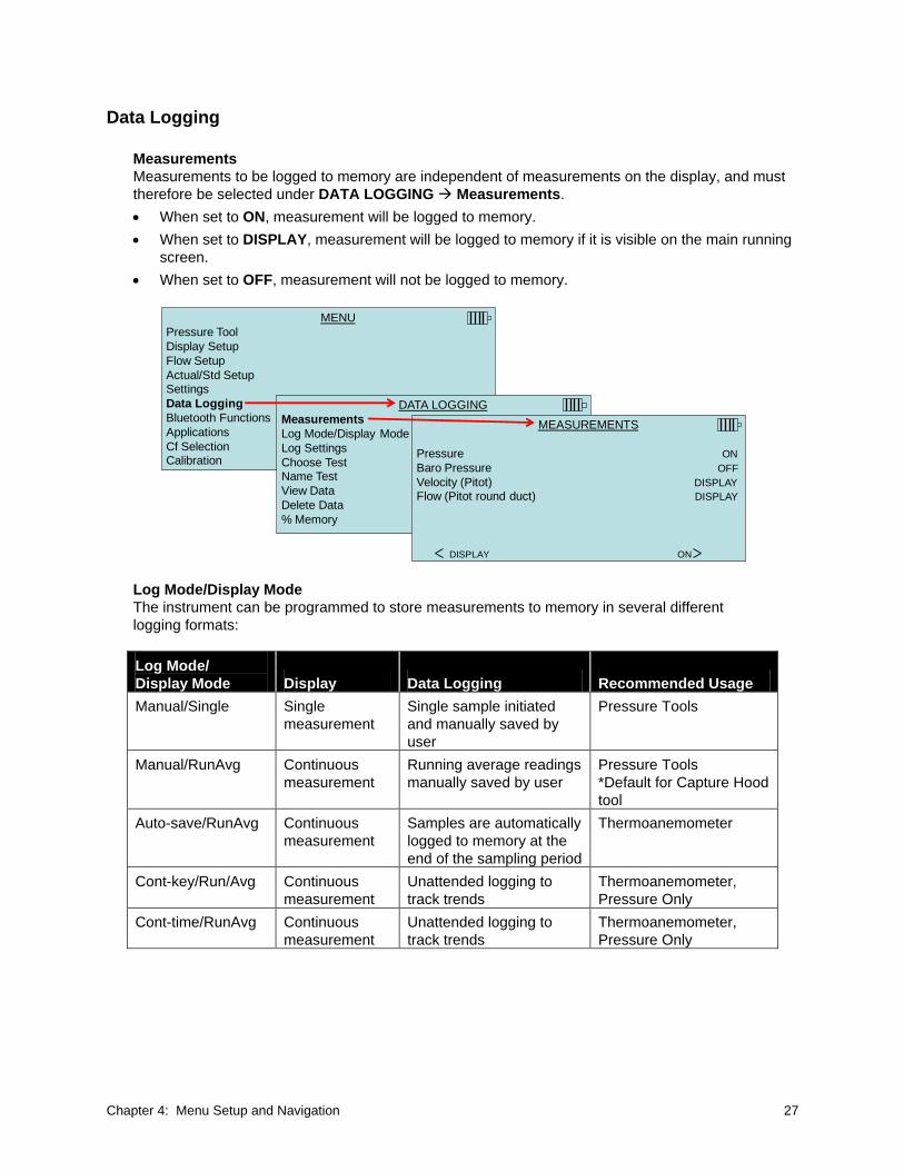
Measurements
Measurements to be logged to memory are independent of measurements on the display, and must
therefore be selected under DATA LOGGING Measurements.
When set to ON, measurement will be logged to memory.
When set to DISPLAY, measurement will be logged to memory if it is visible on the main running
screen.
When set to OFF, measurement will not be logged to memory.
MENU
Pressure Tool
Display Setup
Flow Setup
Actual/Std SetupSettings
Data Logging
Bluetooth Functions
Applications
Cf SelectionCalibration
DATA LOGGING
Measurements
Log Mode/Display Mode Manual/RunAvg
Log Settings
Choose Test Test 001Name Test
View Data
Delete Data
% Memory
MEASUREMENTS
Pressure ON
Baro Pressure OFF
Velocity (Pitot) DISPLAY
Flow (Pitot round duct) DISPLAY
DISPLAY ON
Log Mode/Display Mode
The instrument can be programmed to store measurements to memory in several different
logging formats:
Log Mode/
Display Mode Display Data Logging Recommended Usage
Manual/Single Single
measurement
Single sample initiated
and manually saved by
user
Pressure Tools
Manual/RunAvg Continuous
measurement
Running average readings
manually saved by user
Pressure Tools
*Default for Capture Hood
tool
Auto-save/RunAvg Continuous
measurement
Samples are automatically
logged to memory at the
end of the sampling period
Thermoanemometer
Cont-key/Run/Avg Continuous
measurement
Unattended logging to
track trends
Thermoanemometer,
Pressure Only
Cont-time/RunAvg Continuous
measurement
Unattended logging to
track trends
Thermoanemometer,
Pressure Only

28 Airflow™ Instruments ProHood Capture Hoods PH730/PH731
MENU
Pressure Tool
Display Setup
Flow Setup
Actual/Std SetupSettings
Data Logging
Bluetooth Functions
Applications
Cf SelectionCalibration
DATA LOGGING
Measurements
Log Mode/Display Mode Manual/RunAvg
Log Settings
Choose Test Test 001Name Test
View Data
Delete Data
% Memory
LOG MODE/DISPLAY MODE
Manual/Single
Manual/RunAvg
Auto-Save/RunAvgCont-Key/RunAvg
Cont-Time/RunAvg
The Manual/Single mode is a single reading that manually needs to be saved or discarded by the
user. In this mode, the meter will show ---- and READY. When the READ key is pressed, the
instrument will start to take a reading with a duration based on the Time Constant setting. When the
countdown is complete, a reading will be displayed:
This reading can be saved by pressing the SAVE or key.
The reading can be discarded by pressing ESC.
Pressing READ will discard the current measurement and the meter will start taking a new sample.
Manual/RunAvg
In the Manual/RunAvg mode, the current reading is displayed at all times as an averaged reading.
Pressing READ or the RED switch on the base will freeze the current sample measurement.
o Press SAVE to save the sample and return to the measuring mode.
o ESC will unfreeze and return to the measuring mode.
Pressing SAVE anytime in the running mode will save the current sample and continue measuring.
MENU
Pressure Tool
Display Setup
Flow Setup
Actual/Std SetupSettings
Data Logging
Bluetooth Functions
Applications
Cf SelectionCalibration
DATA LOGGING
Measurements
Log Mode/Display Mode Manual/RunAvg
Log Settings
Choose Test Test 001Name Test
View Data
Delete Data
% Memory
LOG MODE/DISPLAY MODE
Manual/Single
Manual/RunAvg
Auto-Save/RunAvgCont-Key/RunAvg
Cont-Time/RunAvg

Chapter 4: Menu Setup and Navigation 29
Auto-Save/RunAvg Logging
In Auto-Save/RunAvg mode, the user samples are automatically logged to memory at the end of the
sampling period. To start logging, press the key. The Auto-Save/RunAvg mode is recommended
when using the optional thermoanemometer probes.
MENU
Pressure Tool
Display Setup
Flow Setup
Actual/Std SetupSettings
Data Logging
Bluetooth Functions
Applications
Cf SelectionCalibration
DATA LOGGING
Measurements
Log Mode/Display Mode Manual/RunAvg
Log Settings
Choose Test Test 001Name Test
View Data
Delete Data
% Memory
LOG MODE/DISPLAY MODE
Manual/Single
Manual/RunAvg
Auto-Save/RunAvgCont-Key/RunAvg
Cont-Time/RunAvg
When set to Auto- Save/RunAvg, the Sample Time can be adjusted. Sample Time is the time period
over which the Sample will be averaged. Use the arrow keys to make changes and press to
accept.
MENU
Pressure Tool
Display Setup
Flow Setup
Actual/Std SetupSettings
Data Logging
Bluetooth Functions
Applications
Cf SelectionCalibration
DATA LOGGING
Measurements
Log Mode/Display Mode Auto-Save/RunAvg
Log Settings
Choose Test Test 001Name Test
View Data
Delete Data
% Memory
SAMPLE TIME
00:01
Min:Sec
PREVIOUS NEXT
30 Airflow™ Instruments ProHood Capture Hoods PH730/PH731
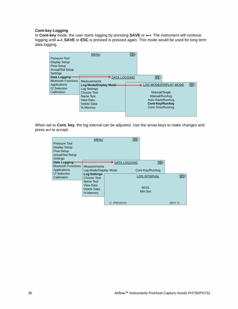
Cont-key Logging
In Cont-key mode, the user starts logging by pressing SAVE or . The instrument will continue
logging until , SAVE or ESC is pressed is pressed again. This mode would be used for long term
data logging.
MENU
Pressure Tool
Display Setup
Flow Setup
Actual/Std SetupSettings
Data Logging
Bluetooth Functions
Applications
Cf SelectionCalibration
DATA LOGGING
Measurements
Log Mode/Display Mode Manual/RunAvg
Log Settings
Choose Test Test 001Name Test
View Data
Delete Data
% Memory
LOG MODE/DISPLAY MODE
Manual/Single
Manual/RunAvg
Auto-Save/RunAvgCont-Key/RunAvg
Cont-Time/RunAvg
When set to Cont. key, the log interval can be adjusted. Use the arrow keys to make changes and
press to accept.
MENU
Pressure Tool
Display Setup
Flow Setup
Actual/Std SetupSettings
Data Logging
Bluetooth Functions
Applications
Cf SelectionCalibration
DATA LOGGING
Measurements
Log Mode/Display Mode Cont-Key/RunAvg
Log Settings
Choose Test Test 001Name Test
View Data
Delete Data
% Memory
LOG INTERVAL
00:01
Min:Sec
PREVIOUS NEXT

Chapter 4: Menu Setup and Navigation 31
Cont-Time/RunAvg Logging
In Cont-Time/RunAvg mode, the user starts taking readings by pressing SAVE or . The
instrument will continue taking samples until the time as set in “Test Length” has elapsed or ESC,
SAVE or is pressed.
MENU
Pressure Tool
Display Setup
Flow Setup
Actual/Std SetupSettings
Data Logging
Bluetooth Functions
Applications
Cf SelectionCalibration
DATA LOGGING
Measurements
Log Mode/Display Mode Manual/RunAvg
Log Settings
Choose Test Test 001Name Test
View Data
Delete Data
% Memory
LOG MODE/DISPLAY MODE
Manual/Single
Manual/RunAvg
Auto-Save/RunAvgCont-Key/RunAvg
Cont-Time/RunAvg
When set to Cont.-time, the log interval and test length can be adjusted.
MENU
Pressure Tool
Display Setup
Flow Setup
Actual/Std SetupSettings
Data Logging
Bluetooth Functions
Applications
Cf SelectionCalibration
DATA LOGGING
Measurements
Log Mode/Display Mode Cont-Time/RunAvg
Log Settings
Choose Test Test 001Name Test
View Data
Delete Data
% Memory
LOG SETTINGS
Log Interval 00:01
Test Length 00:00:01
LOG INTERVAL
00:01
Min:Sec
PREVIOUS NEXT
TEST LENGTH
00 : 00 : 05
Day:Hour:Min
PREVIOUS NEXT

32 Airflow™ Instruments ProHood Capture Hoods PH730/PH731
Choose Test
Test IDs consist of a group of Samples that are used to determine statistics (average, minimum, and
maximum) of a measurement application. The instrument can store 26,500+ samples and 100 test
IDs (one sample can contain multiple measurement parameters such as flow and temperature).
Example: Each duct traverse will have its own Test ID consisting of several Samples.
Pressing NEW will advance to the next available Test ID. Pressing DATES will list the date the Test
was taken.
MENU
Pressure Tool
Display Setup
Flow Setup
Actual/Std SetupSettings
Data Logging
Bluetooth Functions
Applications
Cf SelectionCalibration
DATA LOGGING
Measurements
Log Mode/Display Mode Manual/RunAvg
Log Settings
Choose Test Test 001Name Test
View Data
Delete Data
% Memory
CHOOSE TEST
Test 001 9 Samples
Test 002 7 Samples
Test 003 20 Samples
Test 004 15 SamplesTest 005 38 Samples
Test 006 12 Samples
Test 007 0 Samples
NEW DATES
Name Test
This option allows for customizing the Test ID name using eight (8) characters maximum. Use the
arrow keys to move the cursor to a desired location, press to accept. Repeat until the desired
name appears. Press SAVE to store custom ID name.
MENU
Pressure Tool
Display Setup
Flow Setup
Actual/Std SetupSettings
Data Logging
Bluetooth Functions
Applications
Cf SelectionCalibration
DATA LOGGING
Measurements
Log Mode/Display Mode Manual/RunAvg
Log Settings
Choose Test Test 001Name Test
View Data
Delete Data
% Memory
NAME TEST
T S I 1 2 3 4 5
0 1 2 3 4 5 6 7 8 9A B C D E F G H I J
K L M N O P Q R S T
U V W X Y Z _ ←
PREVIOUS NEXT

Chapter 4: Menu Setup and Navigation 33
View Data/Choose Test
To view stored data, first select the Test ID that contains the data to be recalled. This is accomplished
in the Choose Test menu.
MENU
Pressure Tool
Display Setup
Flow Setup
Actual/Std SetupSettings
Data Logging
Bluetooth Functions
Applications
Cf SelectionCalibration
DATA LOGGING
Measurements
Log Mode/Display Mode Manual/RunAvg
Log Settings
Choose Test Test 001Name Test
View Data
Delete Data
% Memory
VIEW DATA
Choose Test Test 001
View Stats
View Samples
Print Test
PREVIOUS NEXT
CHOOSE TEST
Test 001 9 Samples
Test 002 7 Samples
Test 003 20 Samples
Test 004 15 SamplesTest 005 38 Samples
Test 006 12 Samples
Test 007 0 Samples
NEW DATES
View Stats
Displays statistics (average, minimum, and maximum) of a selected Test ID and the number of
samples, date and time the samples were taken.
MENU
Pressure Tool
Display Setup
Flow Setup
Actual/Std SetupSettings
Data Logging
Bluetooth Functions
Applications
Cf SelectionCalibration
DATA LOGGING
Measurements
Log Mode/Display Mode Manual/RunAvg
Log Settings
Choose Test Test 001Name Test
View Data
Delete Data
% Memory
VIEW DATA
Choose Test Test 022
View Stats
View Samples
Print Test
Use the and arrow keys to view statistics of all the measurement parameters stored in a Test ID.
TEST 022
Velocity (TA)
Avg 250 ft/min
Min 219 ft/min
Max 272 ft/min# Samples 3
03/15/12 09:01:39 AM
PREVIOUS NEXT
TEST 022
Temperature
Avg 74.0 F
Min 73.8 F
Max 74.3 F# Samples 3
03/15/12 09:01:39 AM
PREVIOUS NEXT
TEST 022
%RH
Avg 28.5 %RH TA
Min 28.4 %RH TA
Max 28.6 %RH TA# Samples 3
03/15/12 09:01:39 AM
PREVIOUS NEXT
Example: TEST 022 has three (3) samples, each sample consists of a velocity, temperature, and
relative humidity reading. Use the < or > keys to view statistics of each measurement parameter.

34 Airflow™ Instruments ProHood Capture Hoods PH730/PH731
View Samples
MENU
Pressure Tool
Display Setup
Flow Setup
Actual/Std SetupSettings
Data Logging
Bluetooth Functions
Applications
Cf SelectionCalibration
DATA LOGGING
Measurements
Log Mode/Display Mode Manual/RunAvg
Log Settings
Choose Test Test 001Name Test
View Data
Delete Data
% Memory
VIEW DATA
Choose Test Test 022
View Stats
View Samples
Print Test
Use the and arrow keys to view samples of all the measurement parameters stored in a Test ID.
TEST 022Velocity (TA)
Sample 1 272 ft/min
Sample 2 260 ft/min
Sample 3 219 ft/min
PREVIOUS NEXT
TEST 022Temperature
Sample 1 73.8 F
Sample 2 74.3 F
Sample 3 74.1 F
PREVIOUS NEXT
TEST 022%rh
Sample 1 28.6 %rh
Sample 2 28.5 %rh
Sample 3 28.4 %rh
PREVIOUS NEXT
The meter can send this data to the optional Model 8934 wireless printer or PC capable of Bluetooth
communications. To use the PRINT key, Bluetooth communications must be established between the
meter and the Model 8934 wireless printer or PC set up with Bluetooth communications.
Print Test
Press to print all statistics and samples for the selected Test ID.
MENU
Pressure Tool
Display Setup
Flow Setup
Actual/Std SetupSettings
Data Logging
Bluetooth Functions
Applications
Cf SelectionCalibration
DATA LOGGING
Measurements
Log Mode/Display Mode Manual/RunAvg
Log Settings
Choose Test Test 001Name Test
View Data
Delete Data
% Memory
VIEW DATA
Choose Test Test 022
View Stats
View Samples
Print Test
The meter can send this data to the optional Model 8934 wireless printer or PC capable of Bluetooth
communications. To use the PRINT command, Bluetooth communications must be established
between the meter and the Model 8934 wireless printer or PC set up with Bluetooth communications.
For more information on establishing Bluetooth connections, refer to Application Note AF-150.

Chapter 4: Menu Setup and Navigation 35
Delete Data
Use this menu item to delete all data, delete test or delete a sample.
MENU
Pressure Tool
Display Setup
Flow Setup
Actual/Std SetupSettings
Data Logging
Bluetooth Functions
Applications
Cf SelectionCalibration
DATA LOGGING
Measurements
Log Mode/Display Mode Manual/RunAvg
Log Settings
Choose Test Test 022Name Test
View Data
Delete Data
% MemoryDELETE DATA
Delete All
Delete Test
Delete Sample
Delete All will clear stored data in all Test IDs.
MENU
Pressure Tool
Display Setup
Flow Setup
Actual/Std SetupSettings
Data Logging
Bluetooth Functions
Applications
Cf SelectionCalibration
DATA LOGGING
Measurements
Log Mode/Display Mode Manual/RunAvg
Log Settings
Choose Test Test 022Name Test
View Data
Delete Data
% MemoryDELETE DATA
Delete All
Delete Test
Delete Sample
DELETE ALL
Are you sure?
YES NO

36 Airflow™ Instruments ProHood Capture Hoods PH730/PH731
Delete Test will clear stored data in an individual Test ID selected by the user.
MENU
Pressure Tool
Display Setup
Flow Setup
Actual/Std SetupSettings
Data Logging
Bluetooth Functions
Applications
Cf SelectionCalibration
DATA LOGGING
Measurements
Log Mode/Display Mode Manual/RunAvg
Log Settings
Choose Test Test 005Name Test
View Data
Delete Data
% MemoryDELETE DATA
Delete All
Delete Test
Delete SampleDELETE TEST
Test 001 14 Samples
Test 002 10 Samples
Test 003 12 Samples
Test 004 8 Samples
Test 005 7 Samples
Test 006 15 Samples
Test 007 15 Samples
--- --- DATES
DELETE TEST
Delete Test 005.
Are you sure?
NO YES
Delete Sample will clear the last sample in an individual Test ID selected by the user.
MENU
Pressure Tool
Display Setup
Flow Setup
Actual/Std SetupSettings
Data Logging
Bluetooth Functions
Applications
Cf SelectionCalibration
DATA LOGGING
Measurements
Log Mode/Display Mode Manual/RunAvg
Log Settings
Choose Test Test 005Name Test
View Data
Delete Data
% MemoryDELETE DATA
Delete All
Delete Test
Delete Sample DELETE SAMPLETest 001 14 Samples
Test 002 10 Samples
Test 003 12 Samples
Test 004 8 Samples
Test 005 7 Samples
Test 006 15 Samples
Test 007 15 Samples
--- --- DATES
DELETE SAMPLE
Test 005
Sample 702/15/12 04:55:03 PM
DELETE

Chapter 4: Menu Setup and Navigation 37
% Memory
This option displays the memory available. Delete All, under Delete Data, will clear memory and
reset the memory available to 100%.
DATA LOGGING
Measurements
Log Mode/Display Mode Manual/RunAvg
Log Settings
Choose Test Test 001Name Test
View Data
Delete Data
% Memory MEMORY
Test ID 83 %
Sample 92 %
Bluetooth Functions
The meter contains a Bluetooth Functions menu which is used to adjust parameters to assist with
wireless connections to other Bluetooth capable devices.
MENU
Pressure Tool
Display Setup
Flow Setup
Actual/Std SetupSettings
Data Logging
Bluetooth Functions
Applications
Cf SelectionCalibration
BLUETOOTH FUNCT.
Discover Devices
Discoverability Enable
PINcode 0000
# AutoConnects 1
Discover Devices
Start the Bluetooth process of finding other devices from the meter.
Discoverability
Describes whether another device can discover the meter. Options include:
Disable The instrument is not discoverable by other devices.
Temporary Allows the instrument to be discoverable until another device pairs with it or until the instrument power is turned off and back on.
Enable Makes the instrument discoverable indefinitely.

38 Airflow™ Instruments ProHood Capture Hoods PH730/PH731
PINcode
The PINcode is a security key to be entered into the computer if prompted. The factory default
PINcode is 0000.
Note
PINcode must be set to 0000 in order to use 8934 printer.
# AutoConnects
Specifies how many times the instrument will attempt to reattach to a paired device after the power is
turned on. For this option, the instrument Discoverability setting must be enabled. Settings are 0 to 5
times.
For more information on establishing Bluetooth connections to a PC or 8934 printer, refer to
Application Note AF-150.
Applications
This menu option includes specialized measurement protocols used to perform various tests or
investigations. Applications include Heat flow, Turbulence and Log-Tchebycheff Duct Traverse. For more
information on these applications, refer to the following information:
Heat Flow: calculates heat flow by making temperature, humidity, and flow measurements upstream
and downstream of the coil in the duct. Requires thermoanemometer probe 964 or 966. See
Application Note AF-124 for more information.
Turbulence Intensity: turbulence intensity is a scale characterizing turbulence expressed as a
percent. Requires thermoanemometer probe 960, 962, 964 or 966. See Application Note AF-141 for
more information.
Log Tchebycheff (Tcheb) Duct Traverse: See below.
MENU
Pressure Tool Pitot tube
Display Setup
Flow Setup
Actual/Std SetupSettings
Data Logging
Bluetooth Functions
Applications
Cf SelectionCalibration
APPLICATIONS
Heatflow
Turbulence
Log Tcheb Duct Traverse

Chapter 4: Menu Setup and Navigation 39
Log Tcheb Duct Traverse
The Log Tchebycheff duct traverse is a method of determining the average air velocity or air volume
within round or rectangular ductwork. This application will show the round or rectangular duct on the
display along with the number of sample points with insertion depth (inches or millimeters). For more
information on this application and where to take the samples, refer to Appendix B of this manual.
ROUND DUCT MEAS
Move: 0.3 in
597 ft2/min
0:00
SAVE?
Test 001
Sample 1
Velocity or
volume flow based on Primary
selection in Display Setup
Sample
measurement countdown
Test ID Name
and Sample
To input round or rectangular duct dimensions, refer to the Flow Setup section of this manual.
The instrument operation can be configured three different ways depending on what is selected as
the LogMode/DisplayMode selection found in the data Logging menu:
If LogMode/DisplayMode is set to Manual/Single:
Meter will display READY
o Press READ to initiate measurement
o Sample countdown (based on the Time Constant setting) will be displayed
When Sample countdown is complete:
o Press SAVE to store the measurement sample
o Press ESC to discard and repeat measurement
When Sample is saved, meter will prompt user to move probe to the next sample point
If LogMode/DisplayMode is set to Manual/RunAvg:
Meter will continuously display a reading
User can press SAVE at any time
o Meter will store sample and prompt user to move probe to the next sample point
If LogMode/DisplayMode is set to AutoSave/RunAvg:
Meter will continuously display a reading
User can press SAVE at any time
o Sample countdown (based on the Sample Time) will appear
o When countdown is completed, measurement will be stored to memory and user will
be prompted to move probe to next sample point.
At anytime during the duct traverse, user can press STATS to display statistics of current traverse
(Test ID).
C A U T I O N Do not exit the application while in the middle of the traverse. You will be unable
to return and complete the remaining test points. The traverse will need to be
repeated.

40 Airflow™ Instruments ProHood Capture Hoods PH730/PH731
Calibration Factor (Cf) Selection
The correction factor is an offset that can be applied to the velocity measurements when using the
AF Probe, Pitot tube and Velocity Matrix or flow when using the Capture Hood. An offset of ±50%
(0.50 to 1.50) can be applied to the measurement.
Depending on what is selected as the Pressure Tool will determine what measurement tool is displayed
on the Cf Selection screen.
Note
Calibration factors are not available for the Pressure Only or Flow/K-factor tools.
Calibration
The Calibration Menu lists measurement parameters that can be adjusted in the field. The appropriate
detachable probes must be attached to the meter before field calibration can be undertaken except for
pressure and barometric pressure calibration.
MENU
Pressure Tool
Display Setup
Flow Setup
Actual/Std SetupSettings
Data Logging
Bluetooth Functions
Applications
Cf SelectionCalibration
CALIBRATION
Calibrate Temp
Calibrate Vel
Calibrate %RH
Calibrate PressCalibrate B.P.
Calibrate Hood
Restore Factory Cal

Chapter 4: Menu Setup and Navigation 41
Printing Data Using the Portable Printer
To print logged data, first enter the DATALOGGING menu. Then, use the CHOOSE TEST item to select
the data to be printed. After the test is selected, use the VIEW STATS and VIEW SAMPLES items to
select statistics or individual data points to view and print. After selecting VIEW STATS or VIEW
SAMPLES, press the PRINT key to print the data.
LogDat-CH™ Downloading Software
The instrument also includes downloading software called LogDat-CH. LogDat-CH software transfers the
stored data from the meter to a computer as a spreadsheet file. This software is useful for applications
such as duct traverses, fume hood, and filter face velocity testing.
Follow the instructions on the label of the LogDat-CH software to install the software on your computer.
The software is shipped on a CD-ROM and includes a User’s Guide and Installation Instructions. Updates
are available from the TSI website at http://www.tsi.com/SoftwareDownloads.
To download data from the meter, connect the supplied computer interface USB cable to the meter and to
a computer USB port. Any USB port can be used.

42 Airflow™ Instruments ProHood Capture Hoods PH730/PH731
(This page intentionally left blank)

43
Chapter 5. Changing Capture Hoods
This chapter identifies the flow hood parts and gives instructions for assembling the flow hood.
Capture Hood Parts Identification
Figure 15 identifies the major parts of the capture hood, which are described in the following paragraphs.
Before using the hood, please familiarize yourself with the various parts. You may also refer to Tables 1
through 3.
2
3
4
1
5
1 Fabric hood - Basic hood assembly
2 Base allows micromanometer to be attached
3 Micromanometer with display
4 Flap Actuator
5 Read Switch
Figure 15: Flow Hood Components
Capture Hood Assembly
The Capture Hood is shipped from the factory partially assembled with the 2 ft 2 ft (610 mm 610 mm)
nylon hood attached to the base. If you wish to use another hood size, see “Changing Capture Hoods”.
To complete the assembly of the 2 ft 2 ft (610 mm 610 mm) hood, follow these six steps:
1. Place the base of the capture hood on the floor.
2. Lift the top of the fabric. Insert one end of a support pole into its pole mount in the base. There is a
cup in each corner of the frame to accept the other end of each support pole.
3. Grasp the support pole. Bend the pole slightly to insert the top end of the pole into the support pole
cup located in the opposite corner of the fabric frame. The poles are connected to the frame corners
in a crisscross fashion as shown in Figure 16.

44 Airflow™ Instruments ProHood Capture Hoods PH730/PH731
Figure 16: Installing a Support Pole
4. Insert the second support pole into the pole mount on the opposite side of the base.
5. Repeat step 3 for the second support pole.
6. Repeat steps 4 and 5 for the remaining two support poles.
Four other hood sizes are available from TSI and can be purchased separately. Available hood sizes are
identified by the dimensions of the frame structure at the top of the hood and include 2 ft 4 ft
(610 mm 1220 mm), 1 ft 4 ft (305 mm 1220 mm), 1 ft 5 ft (305 mm 1525 mm) and 3 ft 3 ft
(915 mm 915 mm).
To change hood sizes, first remove the hood currently attached to the base. To remove the attached
hood, first unlatch the cinch belt where the fabric is attached to the base. Then remove the fabric from its
frame structure by pulling the shock cord out of the aluminum frame. Finally, fold up the fabric you just
removed so that it can fit into one of the accessory pockets inside the carrying case. It is a good idea to
fold the fabric so that the tag identifying its size remains visible for future reference.
(continued on next page)

Chapter 5: Changing Capture Hoods 45
Alternate Hood Installation
Refer to Figures 17 through 20 to determine the frame channels needed to assemble any of the standard
sized frames. Select the pieces required for the frame size desired and assemble with the aid of the
appropriate figure. Each channel is labeled with its number for easy identification. Several sections
(numbers 1, 3, and 4) consist of a straight channel portion (each a different length) and a corner piece.
This corner piece has an eyelet and slot arrangement which mates with a similar eyelet and slot at the
end of the straight portion of the channel pieces (see Figure 17). These pieces can be slid together and
are self-locking by means of a retention spring. The arrangement forms a rugged frame which is
additionally strengthened when the hood is attached.
Figure 17: 1 ft 4 ft (305 mm 1220 mm) hood and frame. The support poles always cross as pairs at the
front and back of the fabric hood. For the 1 ft 4 ft (305 mm 1220 mm), the support poles are inserted into
the outside ferrule locations.
2
1
3
1
2 3
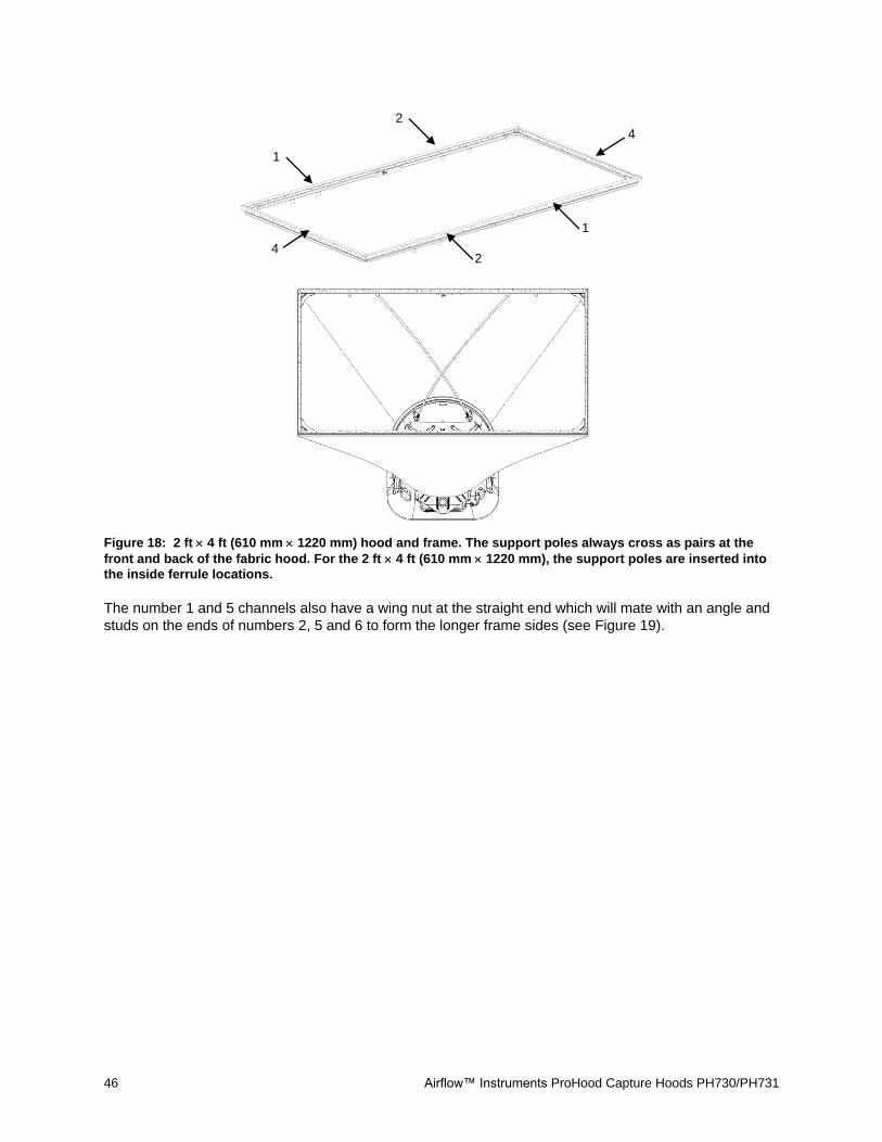
46 Airflow™ Instruments ProHood Capture Hoods PH730/PH731
Figure 18: 2 ft 4 ft (610 mm 1220 mm) hood and frame. The support poles always cross as pairs at the
front and back of the fabric hood. For the 2 ft 4 ft (610 mm 1220 mm), the support poles are inserted into
the inside ferrule locations.
The number 1 and 5 channels also have a wing nut at the straight end which will mate with an angle and
studs on the ends of numbers 2, 5 and 6 to form the longer frame sides (see Figure 19).
2
1
4
1
2 4

Chapter 5: Changing Capture Hoods 47
Figure 19: 1 ft 5 ft (305 mm 1525 mm) hood and frame. The support poles always cross as pairs at the
front and back of the fabric hood. For the 1 ft 5 ft (305 mm 1525 mm), the support poles are inserted into
the inside ferrule locations.
2
1
3
1
2 3
5
5

48 Airflow™ Instruments ProHood Capture Hoods PH730/PH731
Figure 20: 3 ft 3 ft (915 mm 915 mm) hood and frame. The support poles always cross as pairs at the
front and back of the fabric hood. For the 3 ft 3 ft (915 mm 915 mm), the support poles are inserted into
the outside ferrule locations.
Figure 21: Frame Corner Assembly
1
6
6
1
6
1 6
1

Chapter 5: Changing Capture Hoods 49
Figure 22: Frame Side Coupler Assembly
Each hood is constructed in a trapezoidal shape, sewn together so that one open end forms a round
attachment to the base, and the other forms a square or rectangle large enough to fit its matching frame
assembly. Around the frame end of the hood, an elastic shock cord has been sewn into the hood. This
cord is of a size such that it can be pushed into the open side of the U-shaped channels of the frame.
In general, attach a hood to the frame first, and then to the base unit. By stretching around the frame
corners the cord is slightly reduced in diameter and is easier to press into the frame channel.
Note
The hood corners should always be aligned with the corners of the base, near the hood support
brackets. The base has rivets located in the corners which can be used as a guide for aligning
the hood corners.
Direct Inflow Measurement Hood for Biological Safety Cabinets
The BSC hood kits for the models PH731 are designed to measure the inflow or exhaust flow through a
biological safety cabinet (see Figure 23). Part numbers and description of each kit can be found in
Table 2 of this manual.
Figure 23: Direct Inflow Measurement Hood

50 Airflow™ Instruments ProHood Capture Hoods PH730/PH731
The direct inflow BSC hood includes (see Figure 24):
Fixed frame assembly with four removable flaps
Fabric hood
Hood support poles
Base mounting hardware (threaded insert, washer, and screw)
Telescopic pole stand with case to freely hold the capture hood in a vertical position when mounted to
a biological safety cabinet or lab hood
Figure 24: Direct Inflow Measurement Hood Components
To complete the assembly of the BSC hood, follow these seven steps:
1. Remove the plug located at the back of the base assembly and insert the Philips screw with washer
into the hole from the inside of the base (see Figure 25). Place the threaded insert on the outside of
the base opposite the screw and tighten with a Philips screwdriver.
Figure 25: Remove Plug Located at Back of Base Assembly
2. Attach the fabric hood and hood support poles to the frame and base assembly in the same manner
as previously described for the other hood sizes.

Chapter 5: Changing Capture Hoods 51
3. Insert the flaps into the slots from the side of the frame where the fabric hood is attached to the
U-channel of the frame (see Figure 26). Use the different flap lengths to fit various cabinet widths.
Figure 26: Attach Fabric Hood and Hood Support Poles to Frame and Base Assembly
4. Mount the capture hood base to the telescopic stand by fastening the screw on the telescopic stand
to the threaded insert mounted on the base opposite the display/manometer (see Figure 27).
Figure 27: Mount Hood Base to Telescopic Stand

52 Airflow™ Instruments ProHood Capture Hoods PH730/PH731
5. Adjust the height and position of the telescopic stand so that the bottom part of the hood frame rests
against the cabinet opening, and the capture hood is horizontal to the cabinet (see Figure 28).
Figure 28: Adjust Height and Position of Telescopic Stand
6. Lower the sash of the cabinet until it rests on the foam lip of the hood frame (see Figure 29).
Figure 29: Lower Sash of Cabinet Until it Rests on Foam Lip of Hood Frame

Chapter 5: Changing Capture Hoods 53
7. Adjust the flaps to cover the opening of the cabinet. Tape the edges of the flaps to the sash and
frame of the cabinet to create a tight fit. The unit is now ready to make measurements
(see Figure 30).
Figure 30: Unit Ready to Make Measurements

54 Airflow™ Instruments ProHood Capture Hoods PH730/PH731
(This page intentionally left blank)

55
Chapter 6. Flow Measurements Using the Capture Hood
There are two methods of making flow measurement using Capture Hood: (1) Capture Hood (non-backpressure compensation).
(2) Capture Hood with backpressure compensation.
(See “Appendix A. Back Pressure,” for an explanation of the implications of capture hood-induced back
pressure on the measured flow.) Supply or return flows can be measured with both methods, and return flow is indicated as a negative
number. In addition, flow measurements can be performed by taking a single reading or running average
(continuous) reading mode.
Note
Keep the Capture Hood in place during the entire measurement; otherwise, the reading will be
in error.
C A U T I O N WHILE USING THE PROHOOD CAPTURE HOOD TO TEST AIR FLOW IN DUCTS, YOU MAY
COME INTO CONTACT WITH OR BE EXPOSED TO DUST, POLLEN, MOLD, FUNGUS, OR
OTHER AIRBORNE CONTAMINANTS. IF YOU ARE OR MAY BE SENSITIVE TO DUST, POLLEN,
MOLD, FUNGUS, OR OTHER AIRBORNE CONTAMINANTS, ALWAYS USE AN APPROPRIATE
MASK OR RESPIRATOR WHILE EMPLOYING THE PROHOOD CAPTURE HOOD.
Single Reading Measurements
Single reading measurements are individual flow measurements initiated by pressing either the “READ”
button on the meter or the red switch on the left side of the base. Depending on the flow being measured,
a single reading will take one to eight seconds to complete (lower flows take longer).
Once the measurement is complete, the flow value will be displayed. Press SAVE to log to memory, or
press READ, or red switch, to take a new measurement.
To measure in this mode:
1. Select Capture Hood or Hood BP Comp in the Pressure Tool menu.
2. Set the Data Logging mode to Manual/Single.
3. Set the Time Constant to 5 seconds.

56 Airflow™ Instruments ProHood Capture Hoods PH730/PH731
Running Average Measurements
In this mode, the instrument will measure continuously while displaying a running average of flow.
Pressing either the READ key on the meter or the red switch on the base will hold the current reading. To
restart the running average measurement, press the READ key or the red switch. The SAVE key can be
used at any time to log to memory.
To measure in this mode:
1. Select Capture Hood or Hood BP Comp in the Pressure Tool menu.
2. Set the Data Logging mode to Manual/Single.
3. Set the Time Constant to 5 seconds.
Capture Hood Measurements (non-backpressure compensated)
Non-backpressure compensated measurements can only be made with backpressure flap in the “OPEN”
position. If the flap is closed or partially closed, the meter will display the message “OPEN THE FLAP”.
Backpressure Compensated Measurements
In the backpressure compensated, a correction is applied to account for the change in flow due to the
presence of the Capture Hood. In most cases, backpressure compensated measurements will provide
the most satisfactory flow measurement results, especially when the flow is greater than 500 ft3/min
(850 m3/hr, 235 l/s).
Make sure that “Capture Hood Back with Pressure Compensation” is selected from the Pressure Tools
menu.
Backpressure compensated measurement require two sequential measurements: first with the back
pressure flap “OPEN” and then with the flap “CLOSED”.
Follow the sequence of operation as described below:
1. Place the Capture Hood over the diffuser, grill or other opening through which you wish to make a
measurement.
2. Open the backpressure flap. This is done by pressing up on the flap handle with your left hand as you
hold the hood in place. Press until the flap clicks into full open position.
3. Press the red switch. The message “OPEN” will be displayed as the meter takes the reading. (In very
low flows, this step and step 5 may take up to eight (8) seconds each. Higher flows will require
less time.)
4. Wait for the message “CLOSE FLAP” then close the flap by pulling down on the flap handle until it
clicks into the fully closed position.
5. Press the red trigger button. The message ”CLOSED” will be displayed as the meter take the
reading.
6. The backpressure compensated measurement value will appear and remain on the display until
another reading is initiated, or other meter function is initiated. To log reading to memory,
press SAVE.

Chapter 6: Flow Measurements Using the Capture Hood 57
Note
It is important that the capture hood see the same flow for both parts of the backpressure
compensated flow measurement. It is best to keep the Capture Hood in place for both
measurements, but it is alright to remove and replace the Capture Hood between the two
readings. However, if the flow is changed or changing between the two measurements, the
measurement results will be inaccurate.
“ERROR” Display
For the backpressure compensation measurement to be meaningful, the measurement in the flap
“OPEN” position must be higher than the measurement in the flap “CLOSED” position. If this is not true,
the ProHood meter will display an error: backpressure open greater than closed.

58 Airflow™ Instruments ProHood Capture Hoods PH730/PH731
(This page intentionally left blank)

59
Chapter 7. Maintenance and Troubleshooting
The ProHood Capture Hood PH730/PH731 is designed for long-term field use. If used with reasonable
care, it should be able to make precise measurements over a long time period. Some of the components
can be cleaned periodically. When cleaning the components, please follow the instructions given below.
Fabric Hood
The hoods can be washed with mild detergent and cold water. When washing the hood, keep the hood
away from objects with sharp corners or sharp edges. Careless cleaning may cause damage.
If the fabric gets ripped it should be replaced or repaired. Duct tape can be placed over the rip on both
sides of the fabric for temporary repair.
To replace a damaged fabric or to order a different fabric size, contact your local TSI/Airflow Instruments
products distributor. To determine who your local TSI/Airflow Instruments products distributor is, you may
call toll-free at (800) 874-2811 (USA) or (1) 651-490-2811 (International).
Micromanometer
The micromanometer case, display screen and keys can be cleaned using a damp cloth with mild
detergent solution. Do not immerse it in water. Wipe the unit dry before use.
Manifold
If you observe the flow sensing taps of the manifold becoming clogged with dust or other material, clean
them with a damp cloth. The manifold should be kept in place during cleaning. Do not apply excessive
forces on the grid of the manifold. If any part of the grid is damaged, please contact Customer Service for
repair information.
Cases
If the instrument case or storage case needs cleaning, wipe it off with a soft cloth and isopropyl alcohol or
a mild detergent.
Calibration
TSI recommends an annual calibration for the instrument. For a nominal fee, we will calibrate the unit and
return it to you with a certificate of calibration and NIST traceability. This “annual checkup” assures you of
consistently accurate readings. To calibrate the instrument, please ship the complete package that
includes the meter, the base, the manifold and any fabrics used. Everything should be packed carefully
within the carrying case and then inside a shipping box. The original shipping box is preferred. Before
sending your instrument for calibration or repair, obtain a Return Material Authorization (RMA) number by
visiting our website at http://rma.tsi.com or contacting customer service. When obtaining an RMA number,
you will also learn the cost of service or calibration and receive shipping instructions.
Table 4 list the symptoms, possible causes, and recommended solutions for common problems
encountered with the instrument. If your symptom is not listed, or if none of the solutions solves your
problem, please contact the factory.
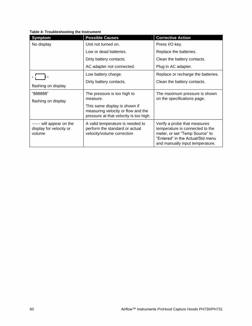
60 Airflow™ Instruments ProHood Capture Hoods PH730/PH731
Table 4: Troubleshooting the Instrument
Symptom Possible Causes Corrective Action
No display Unit not turned on.
Low or dead batteries.
Dirty battery contacts.
AC adapter not connected.
Press I/O key.
Replace the batteries.
Clean the battery contacts.
Plug in AC adapter.
“ ”
flashing on display
Low battery charge.
Dirty battery contacts.
Replace or recharge the batteries.
Clean the battery contacts.
“888888”
flashing on display
The pressure is too high to
measure.
This same display is shown if
measuring velocity or flow and the
pressure at that velocity is too high.
The maximum pressure is shown
on the specifications page.
------ will appear on the
display for velocity or
volume
A valid temperature is needed to
perform the standard or actual
velocity/volume correction
Verify a probe that measures
temperature is connected to the
meter, or set “Temp Source” to
“Entered” in the Actual/Std menu
and manually input temperature.

61
Appendix A. Back Pressure
The quantity of air flowing through a supply diffuser or a return grille is reduced to some extent whenever
a capture hood is placed over the flow opening. The amount of flow reduction will vary depending on the
combined effects of the diffuser/grille resistance, the capture hood resistance, system pressure and the
flow rate.
The PH731 capture hood features a built-in capability to make flow measurements which are
compensated for the effects of the capture hood-induced back pressure. This is accomplished by taking
two sequential flow measurements at a diffuser or grille, the first with the back pressure flap “OPEN” and
the second with the flap “CLOSED”. The resulting Backpressure Compensated Flow displayed by the
meter represents the air flow through the diffuser/grille in its original state, that is, without the presence of
the capture hood.
Verifying Flow Measurements
It is always the recommended practice to verify the flow measurements obtained with a capture hood by
performing appropriate* multi-point, in-duct velocity traverses using a Pitot-static tube or a thermal
anemometer.
We recommend the use of the Log-linear method when traversing a round duct, and the Log-Tchebycheff
method when traversing a rectangular duct.
*We recommend that you refer to the most up-to-date copy of the duct traverse specification you require from an approved regulatory or professional organization.

62 Airflow™ Instruments ProHood Capture Hoods PH730/PH731
(This page intentionally left blank)

63
Appendix B. Traversing a Duct to Determine Average Air Velocity or Volume
The following techniques can be used to measure air flow inside ducts, using a velocity probe or pitot-
static tube. When using a pitot-static tube, the individual velocities must be calculated for each pressure
reading and then averaged together. Averaging pressure with a pitot tube and then converting into
velocity will give an incorrect result, especially if many readings are more than ±25% from the average
pressure. Remember that for a pitot tube, velocity is proportional to the square root of pressure.
Where to Take the Measurement
In order to make air velocity measurements in a duct, it is best to measure at least 7.5 duct diameters
downstream and at least 3 duct diameters upstream from any turns or flow obstructions. It is possible to
do a traverse as little as 2 duct diameters downstream and 1 duct diameter upstream from obstructions,
but measurement accuracy will be impaired. When measuring rectangular ducts, use this formula to find
the equivalent diameter of the duct when calculating how much distance is 7.5 diameters downstream
and 3 diameters upstream:
Equivalent Diameter = sq root of 4HV / Pi
Where:
H = horizontal duct dimension
V = vertical duct dimension
Pi = 3.14
It is also possible to take a single reading to measure air velocity or air volume flow in a duct, measuring
in the center of the duct and multiplying the reading by 0.9 to correct for the higher velocity at the center
of the duct. If conditions are very good an accuracy of ±5 or ±10 percent may be obtained this way. This
method is not reliable, however, and should only be used where small duct size or other conditions do not
permit a full traverse.
(continued on next page)

64 Airflow™ Instruments ProHood Capture Hoods PH730/PH731
Traversing a Round Duct
Using the log-Tchebycheff method, the duct is divided into concentric circles, each containing equal area.
An equal number of readings is taken from each circular area, thus obtaining the best average.
Commonly, three concentric circles (6 measuring points per diameter) are used for ducts of 10-inch
diameter and smaller. Four or five concentric circles (8 or 10 measuring points per diameter) are used for
ducts larger than 10-inch diameter.
The preferred method is to drill 3 holes in the duct at 60° angles from each other as shown in Figure 31
below. Three traverses are taken across the duct, averaging the velocities obtained at each measuring
point. Then the average velocity is multiplied by the duct area to get the flow rate. (A different method
uses 2 holes at 90° from each other, decreasing the number of traverses with the probe by one.)
0.032dia
0.135dia0.321dia
0.679dia0.865dia
0.968dia
dia
Figure 31: Location of Measuring Points when Traversing a
Round Duct using Log-Tchebycheff Method
#of Measuring
Points
Per Diameter
Position Relative to Inner Wall
6 0.032, 0.135, 0.321, 0.679, 0.865, 0.968
8 0.021, 0.117, 0.184, 0.345, 0.655, 0.816, 0.883, 0.979
10 0.019, 0.077, 0.153, 0.217, 0.361, 0.639, 0.783, 0.847, 0.923, 0.981
Before taking the measurement, multiply the numbers in the table times the duct diameter to get insertion
depth for the probe. (Do not forget to use the inside dimension of the duct if it is lined with insulation.)

Appendix B: Traversing a Duct to Determine Average Air Velocity or Volume 65
Traversing a Square Duct
Using the log-Tchebycheff method, the duct is divided into rectangular areas, which are further adjusted
in size to account for effects of the duct wall on the airflow. A minimum of 25 points must be measured in
order to get a good average. The number of data points to be taken along each side of the duct depends
on how wide that side of the duct is. For duct sides less than 30 inches, 5 traversal points must be taken
along that side. For duct sides of 30 to 36 inches, 6 points must be taken. For duct sides greater than 36
inches, 7 points must be taken. Multiply the numbers in the table times the duct dimension to get insertion
depth for the probe.
0.061 H
0.235 H0.437 H
0.563 H
0.765 H
0.939 H
H
0.074 V
0.288 V
0.500 V
0.712 V
0.926 V
V
Figure 32: Location of Measuring Points for Traversing a
Rectangular Duct using Log-Tchebycheff Method
For this duct, a 30-36” horizontal dimension requires 6 points (or 6 traverse lines). For this duct, a vertical
dimension less than 30” requires 5 points (or 5 traverse lines).
# of Points or
Traverse Lines
per Side
Position Relative to Inner Wall
5 0.074, 0.288, 0.500, 0.712, 0.926
6 0.061, 0.235, 0.437, 0.563, 0.765, 0.939
7 0.053, 0.203, 0.366, 0.500, 0.634, 0.797, 0.947

66 Airflow™ Instruments ProHood Capture Hoods PH730/PH731
(This page intentionally left blank)

67
Appendix C. Swirl X Flow Conditioner for Airflow Instruments Model PH731 ProHood Capture Hood
Description
The Swirl X Flow Conditioner significantly
reduces the negative effects turbulent airflows
have on the measurement accuracy of
pressure-based capture hoods. The Swirl X
Flow Conditioner creates a more uniform flow
pattern within the hood and is ideally suited for
Swirl or Twist-type supply air diffusers.
Swirl or Twist diffusers, their associated
ductwork and HVAC components are designed
to deliver a volume of air to the targeted space
with movement that entrains or mixes with the
room air and increases optimal temperature
uniformity and minimal sensible draft within the
so-called “occupied zone”.
Air flowing through Swirl or Twist type diffusers
has traditionally caused significant
measurement errors in capture hoods. This is
a remnant of the air flow pattern, which swirls
around the hood and emerges in a highly
uneven distribution across the sensing
manifold of a capture hood. Measurement
errors up to and exceeding 40% of flow can
result, unless a flow conditioner is used inside
the capture hood.
Swirl X Flow
Conditioner

68 Airflow™ Instruments ProHood Capture Hoods PH730/PH731
Performance Data
Performance data obtained in HVAC test laboratory using two high-accuracy flow stations as flow
measurement standards. The flow stations were mounted in sealed ductwork upstream of the tested
Swirl Diffusers.
-20
-10
0
10
20
30
40
0 100 200 300 400 500 600 700
Me
asu
rem
en
t Er
ror
[% o
f Fl
ow
]
Flow [m3/hr]
PH731 Performance Data(Swirl Diffuser on 200mm Dia. Duct)
PH731 with Swirl-X
PH731 (No Swirl-X)
PH731 Allowed Tolerance
-20
-10
0
10
20
30
40
0 200 400 600 800 1000 1200
Mea
sure
men
t Err
or
[% o
f Flo
w]
Flow [m3/hr]
PH731 Performance Data(Swirl Diffuser on 300mm Dia. Duct)
PH731 with Swirl-X
PH731 (no Swirl-X)
PH731 Allowed Tolerance

Appendix C: Swirl X Flow Conditioner for TSI Model 8375 ACCUBALANCE® Air Capture Hood 69
Installation and Usage
1. Put the two pieces together and place it in the base as shown below (it will sit on top of the flange of the base).
2. Install the support rods and 2’ x 2’ (610 mm x 610 mm) frame/fabric.
3. When set up, use hood as normal. There is no need to change K-factors or access any special menus for use.

70 Airflow™ Instruments ProHood Capture Hoods PH730/PH731
(This page intentionally left blank)

Airflow Instruments Models PH730/PH731
Specifications*
*Specifications are subject to change without notice.
Range
Differential pressure ... ±15 in. H2O (3735 pa); 150 in. H2O maximum safe operating pressure
Absolute pressure ...... 15 to 40 in. Hg (356 to
1016 mm Hg)
Velocity ...................... 25 to 15,500 ft/min (0.125 to 78m/s) pitot probes;
25 to 5,000 ft/min (0.125 to 25 m/s) air flow probe;
25 to 2,500 ft/min (0.125 to 12.5 m/s) velocity matrix
Volume ...................... 25 to 2,500 ft3/min (42 to
4250 m3/h) capture hood
supply and return
Temperature .............. 40 to 140°F (-10 to 60°C) base temperature probe
14 to 140°F (-10 to 60°C) temperature/RH probe
40 to 140°F (4.4 to 60°C) operating (electronics)
Storage temperature .. -4 to 160°F (-20 to 71°C)
Rh .............................. 5 to 95% RH temperature/RH probe
Resolution
Pressure .................... 0.00001 in. H2O (0.001 pa) static and differential;
0.01 in. Hg (1 mm Hg) absolute
Velocity ...................... 1 ft/min (.01 m/s)
Volume ...................... 1 ft3/min (1 m
3/h)
Rh .............................. 0.1% RH
Temperature .............. 0.1°F (0.1°C)
Accuracy
Pressure .................... ±2% of reading ±0.0001 in. H2O (0.025 pa) static and differential;
±2% of reading absolute
Velocity ...................... ±3% of reading ±7 ft/min (0.04 m/s) >50 ft/min (>0.25 m/s)
Volume ...................... ±3% of reading ±7 ft3/min
(12 m3/h) >50 ft
3/min (>85
m3/h)
Rh .............................. ±3% RH
Temperature .............. ±0.5°F (0.3°C)
Units
Pressure .................... in. H2O, pa, hPa, kPa, mm Hg, in. Hg, cm Hg, mm H2O, cm H2O
Velocity ...................... ft/min, m/s
Volume ...................... ft3/min, m
3/h, m
3/min, l/s
Temperature .............. degrees F, degrees C
Statistics ...................... min, max, average
Data Storage ................ 26,500 samples, time and date stamped
Logging Interval .......... user selectable
Response Time ............ 2 to 8 seconds, differential pressure sensor
Dimensions
(manometer only) ............. 7.4 in. 4.5 in. 2.3 in.
(18.8 cm 11.4 cm 5.8 cm)
Pressure connection ... ¼ in. OD straight ports with barbed ends for use with 3/16 in. (4.76 mm) ID flexible tubing
Weight with batteries .. PH730 17 oz (0.5 kg); PH731 7.4 lb (3.4 kg)
Power requirements .... four AA-size cells, rechargeable NiMH (included) or alkaline, or AC adapter (included), 7.5 VDC, 1.6 A, regulated
Battery life .................... minimum of 12 hours typical
Recharge time.............. 4 hours (internal charger)

Airflow Instruments, TSI Instruments Ltd. Visit our website at www.airflowinstruments.co.uk for more information. UK Tel: +44 149 4 459200 France Tel: +33 491 11 87 64
Germany Tel: +49 241 523030
P/N 6005724 Rev D ©2014 TSI Incorporated Printed in U.S.A.

The Observator range is in continuous development and so specifications may be subject to change without prior notice.
www.observator.com
Welcome to the world of Observator
Since 1924 Observator has evolved to be a trend-setting developer
and supplier in a wide variety of industries. Originating from the
Netherlands, Observator has grown into an internationally
oriented company with a worldwide distribution network and offices
in Australia, Germany, the Netherlands,
Singapore and the United Kingdom.
We represent this supplier. For more information contact
Observator Instruments:
T: +31 (0)180 463411 E: [email protected]
Rietdekkerstraat 6
2984 BM Ridderkerk
The Netherlands