Embed Size (px)
Citation preview
AIRFLAME EXCEL MK.3AF 18XL 9500360AC 18XL 9500361
INSTALLATION & SERVICING MANUALPatent applied for
9860369/02Please leave these Instructions with the user
This Appliance is for use in the United Kingdom (GB) and the Republicof Ireland (IE) only.
2
IMPORTANT NOTES
If your Wonderfire Airflame Excel Mk.3 burner is to be installed within a mk.3 Wonderfireconvector box, then this manual should be read in conjunction with the convector boxinstallation manual (part number 9860371). This appliance is intended for decorative purposes.Under no circumstances must rubbish or debris of any description be thrown onto the fuel bed.
Please read the following section before commencing with installation.
Before installation, ensure that the local distribution conditions (identification of the type of gasand pressure) and the adjustment of the appliance are compatible.
It is the law that competent persons, in accordance with the Gas Safety (Installation and Use)(amendment) Regulations 1994, install all gas appliances.
Improper installation of this decorative open gas fire could be hazardous to health. This fire isto be used only in a properly flued, incombustible, masonry fireplace with the chimney or fluefree of any obstruction or damper. If in doubt consult building regulations or a supplier.
This appliance must be installed in accordance with the rules in force.The flue must be swept before installation.
This appliance must be fitted in a fireplace opening conforming to BS 1251.
A flue with a minimum diameter of 7”, a minimum effective height of 3 metres, with a goodupward draught is required for fires operating within standard fireplace openings. Largerfireplace openings may require a correspondingly larger chimney diameter, a faulty flue orchimney may result in products of combustion spilling into the room with consequent possibledamage to furniture and decor. Conduct a smoke test before proceeding with installation.
GB only: A permanent ventilation grille of fixed design and having a minimum free area of100cm2 must be fitted with direct access to outside air to room.Note: see convector instructions if being installed within a Wonderfire convector box forventilation requirements.
IE only: This appliance must be installed in accordance with IS 813 1996 (as amended).
We strongly recommend the use of an approved fireguard whenever the elderly, infirm oryoung children are in the presence of a working fire.
The appliance is fitted with an A.S.D. (atmosphere sensing device) if the appliance closesdown after a period of operation for no apparent reason, the consumer should be informed tostop using the appliance, until the installation and appliance have been thoroughly checked.
RELATED DOCUMENTS:
Gas Safety (Installation and Use) Regulations 1994 (as amended) BS 5440 Part 1 1990BS 5871 Pt 3 Installation of Decorative Fuel Effect Fires BS 5440 Part 2 1989Fireplace components conforming to BS 1251 assembled BS 5871 Part 3 1990in accordance With BS 8303-1986 BS 6461 Part 1 1984Relevant Building Regulations BS 6461 Part 2 1984Republic of Ireland: IS 813 1996 (as amended)
3
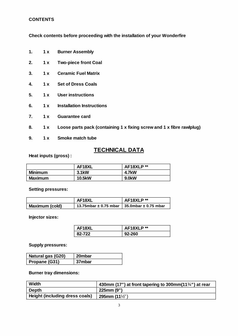
CONTENTS
Check contents before proceeding with the installation of your Wonderfire
1. 1 x Burner Assembly
2. 1 x Two-piece front Coal
3. 1 x Ceramic Fuel Matrix
4. 1 x Set of Dress Coals
5. 1 x User instructions
6. 1 x Installation Instructions
7. 1 x Guarantee card
8. 1 x Loose parts pack (containing 1 x fixing screw and 1 x fibre rawlplug)
9. 1 x Smoke match tube
TECHNICAL DATAHeat inputs (gross) :
AF18XL AF18XLP **Minimum 3.1kW 4.7kWMaximum 10.5kW 9.0kW
Setting pressures:
AF18XL AF18XLP **Maximum (cold) 13.75mbar ± 0.75 mbar 35.0mbar ± 0.75 mbar
Injector sizes:
AF18XL AF18XLP **82-722 92-260
Supply pressures:
Natural gas (G20) 20mbarPropane (G31) 37mbar
Burner tray dimensions:
Width 430mm (17”) at front tapering to 300mm(11¾”) at rearDepth 225mm (9”)Height (including dress coals) 295mm (11½”)
4
** When converted using kit number 9500362INSTALLATION AND COMMISSIONING INSTRUCTIONS
PLEASE READ CAREFULLYBEFORE STARTING WORK
Fireplace, flue and ventilationdetails
Read the important notes on theinside front cover beforeproceeding with the installation ofyour fire. Only when you havecomplied with all of the aboveshould you commence with theinstallation of the appliance.
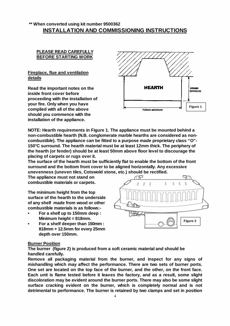
NOTE: Hearth requirements in Figure 1. The appliance must be mounted behind anon-combustible hearth (N.B. conglomerate marble hearths are considered as non-combustible). The appliance can be fitted to a purpose made proprietary class “O”-150°C surround. The hearth material must be at least 12mm thick. The periphery ofthe hearth (or fender) should be at least 50mm above floor level to discourage theplacing of carpets or rugs over it.The surface of the hearth must be sufficiently flat to enable the bottom of the frontsurround and the bottom front cover to be aligned horizontally. Any excessiveunevenness (uneven tiles, Cotswold stone, etc.) should be rectified.The appliance must not stand oncombustible materials or carpets.
The minimum height from the topsurface of the hearth to the undersideof any shelf made from wood or othercombustible materials is as follows:-• For a shelf up to 150mm deep :
Minimum height = 818mm.• For a shelf deeper than 150mm :
818mm + 12.5mm for every 25mmdepth over 150mm.
Burner PositionThe burner (figure 2) is produced from a soft ceramic material and should behandled carefully.Remove all packaging material from the burner, and inspect for any signs ofmishandling which may affect the performance. There are two sets of burner ports.One set are located on the top face of the burner, and the other, on the front face.Each unit is flame tested before it leaves the factory, and as a result, some slightdiscoloration may be evident around the burner ports. There may also be some slightsurface cracking evident on the burner, which is completely normal and is notdetrimental to performance. The burner is retained by two clamps and set in position
Figure 2
Figure 1
5
Figure 3
Figure 4
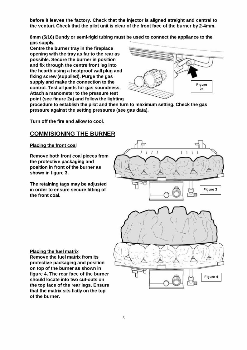
before it leaves the factory. Check that the injector is aligned straight and central tothe venturi. Check that the pilot unit is clear of the front face of the burner by 2-4mm.
8mm (5/16) Bundy or semi-rigid tubing must be used to connect the appliance to thegas supply.Centre the burner tray in the fireplaceopening with the tray as far to the rear aspossible. Secure the burner in positionand fix through the centre front leg intothe hearth using a heatproof wall plug andfixing screw (supplied). Purge the gassupply and make the connection to thecontrol. Test all joints for gas soundness.Attach a manometer to the pressure testpoint (see figure 2a) and follow the lightingprocedure to establish the pilot and then turn to maximum setting. Check the gaspressure against the setting pressures (see gas data).
Turn off the fire and allow to cool.
COMMISIONING THE BURNER
Placing the front coal
Remove both front coal pieces fromthe protective packaging andposition in front of the burner asshown in figure 3.
The retaining tags may be adjustedin order to ensure secure fitting ofthe front coal.
Placing the fuel matrixRemove the fuel matrix from itsprotective packaging and positionon top of the burner as shown infigure 4. The rear face of the burnershould locate into two cut-outs onthe top face of the rear legs. Ensurethat the matrix sits flatly on the topof the burner.
Figure2a
6
Figure 6
Figure 5
Figure 7
Figure 8
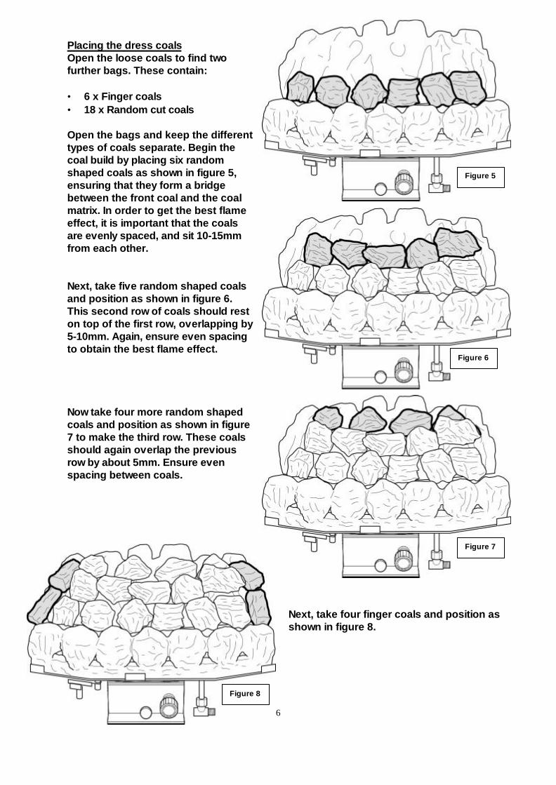
Placing the dress coalsOpen the loose coals to find twofurther bags. These contain:
• 6 x Finger coals• 18 x Random cut coals
Open the bags and keep the differenttypes of coals separate. Begin thecoal build by placing six randomshaped coals as shown in figure 5,ensuring that they form a bridgebetween the front coal and the coalmatrix. In order to get the best flameeffect, it is important that the coalsare evenly spaced, and sit 10-15mmfrom each other.
Next, take five random shaped coalsand position as shown in figure 6.This second row of coals should reston top of the first row, overlapping by5-10mm. Again, ensure even spacingto obtain the best flame effect.
Now take four more random shapedcoals and position as shown in figure7 to make the third row. These coalsshould again overlap the previousrow by about 5mm. Ensure evenspacing between coals.
Next, take four finger coals and position asshown in figure 8.
7
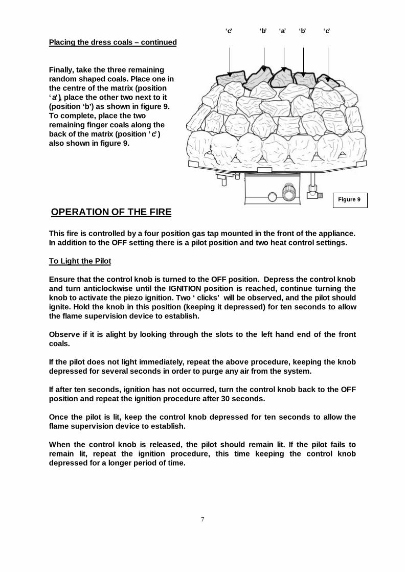
Placing the dress coals – continued
Finally, take the three remainingrandom shaped coals. Place one inthe centre of the matrix (position‘a’), place the other two next to it(position ‘b’) as shown in figure 9.To complete, place the tworemaining finger coals along theback of the matrix (position ‘c’)also shown in figure 9.
OPERATION OF THE FIRE
This fire is controlled by a four position gas tap mounted in the front of the appliance.In addition to the OFF setting there is a pilot position and two heat control settings.
To Light the Pilot
Ensure that the control knob is turned to the OFF position. Depress the control knoband turn anticlockwise until the IGNITION position is reached, continue turning theknob to activate the piezo ignition. Two ‘clicks’ will be observed, and the pilot shouldignite. Hold the knob in this position (keeping it depressed) for ten seconds to allowthe flame supervision device to establish.
Observe if it is alight by looking through the slots to the left hand end of the frontcoals.
If the pilot does not light immediately, repeat the above procedure, keeping the knobdepressed for several seconds in order to purge any air from the system.
If after ten seconds, ignition has not occurred, turn the control knob back to the OFFposition and repeat the ignition procedure after 30 seconds.
Once the pilot is lit, keep the control knob depressed for ten seconds to allow theflame supervision device to establish.
When the control knob is released, the pilot should remain lit. If the pilot fails toremain lit, repeat the ignition procedure, this time keeping the control knobdepressed for a longer period of time.
‘a’‘b’ ‘b’‘c’ ‘c’
Figure 9
8
Operation of the fire – continued
Lighting the Main Burner
Once the pilot light is established the main burner can be lit by turning the controlknob anticlockwise to the HIGH position.
Controlling the heat setting.
In order to change from one setting to another depress the control knob slightly andturn the knob to the required position. Alternatively, if a setting between LOW andHIGH is required, then the control knob may be turned to this position.
Note: We recommend you use the appliance at a low setting for the first few hours ofuse to reduce the thermal cracking of the surface of the burner.Surface cracking of the burner is normal and is no cause for concern. Whist bindingmaterials are being burnt out of the burner there may be a slight odour.
To Turn the Fire back to Pilot Setting
Depress control knob and turn clockwise until pilot setting is reached.To Turn the Fire OFF Ensure control knob is in pilot position, depress control knoband turn clockwise to the OFF position.
For fires fitted with Aeration control
To operate the aeration control system, the following procedure should be followed:
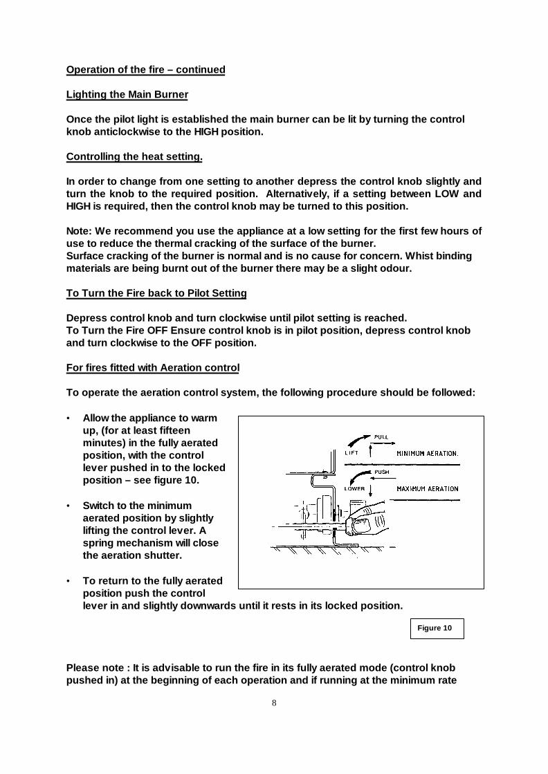
• Allow the appliance to warmup, (for at least fifteenminutes) in the fully aeratedposition, with the controllever pushed in to the lockedposition – see figure 10.
• Switch to the minimumaerated position by slightlylifting the control lever. Aspring mechanism will closethe aeration shutter.
• To return to the fully aeratedposition push the controllever in and slightly downwards until it rests in its locked position.
Please note : It is advisable to run the fire in its fully aerated mode (control knobpushed in) at the beginning of each operation and if running at the minimum rate
Figure 10
9
setting, or to burn off any carbon deposits which may have built up after prolongeduse of the minimum aerated setting.
CLEARANCE TEST
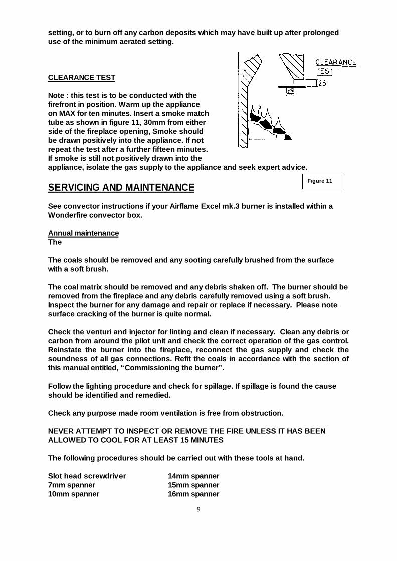
Note : this test is to be conducted with thefirefront in position. Warm up the applianceon MAX for ten minutes. Insert a smoke matchtube as shown in figure 11, 30mm from eitherside of the fireplace opening, Smoke shouldbe drawn positively into the appliance. If notrepeat the test after a further fifteen minutes.If smoke is still not positively drawn into theappliance, isolate the gas supply to the appliance and seek expert advice.
SERVICING AND MAINTENANCE
See convector instructions if your Airflame Excel mk.3 burner is installed within aWonderfire convector box.
Annual maintenanceThe
The coals should be removed and any sooting carefully brushed from the surfacewith a soft brush.
The coal matrix should be removed and any debris shaken off. The burner should beremoved from the fireplace and any debris carefully removed using a soft brush.Inspect the burner for any damage and repair or replace if necessary. Please notesurface cracking of the burner is quite normal.
Check the venturi and injector for linting and clean if necessary. Clean any debris orcarbon from around the pilot unit and check the correct operation of the gas control.Reinstate the burner into the fireplace, reconnect the gas supply and check thesoundness of all gas connections. Refit the coals in accordance with the section ofthis manual entitled, “Commissioning the burner”.
Follow the lighting procedure and check for spillage. If spillage is found the causeshould be identified and remedied.
Check any purpose made room ventilation is free from obstruction.
NEVER ATTEMPT TO INSPECT OR REMOVE THE FIRE UNLESS IT HAS BEENALLOWED TO COOL FOR AT LEAST 15 MINUTES
The following procedures should be carried out with these tools at hand.
Slot head screwdriver 14mm spanner7mm spanner 15mm spanner10mm spanner 16mm spanner
Figure 11
10
11mm spanner 3/4 AF spanner12mm spanner Phillips No.2 type screwdriverExternal circlip pliers
Before servicing the component parts carry out the following procedure:
1. Turn off the appliance and wait least 15 minutes to allow the fire to cool.2. Isolate the gas supply.3. Remove the coals, matrix and front coal.4. Disconnect the inlet supply/appliance union.5. Unscrew the appliance fixing screw.6. Remove the appliance.
To remove the injector:
Carefully invert the burner assembly ensuring that the ceramic surfaces are notdamaged. Disconnect the injector/supply pipe union, place the burner assemblyupright. Remove the injector. Replace in reverse order.
To remove the Piezo unit:
The piezo unit is an integral part of the gas tap : Refer to section ‘To remove gastap’.With the gas tap removed, remove the external circlip that retains the piezo unit.Remove the piezo unit from the tap. Replace in reverse order.
To remove the thermocouple/pilot unit:
The thermocouple is an integral part of the pilot unit, and must be replaced as such.To remove the pilot unit, disconnect the pilot gas feed pipe at the union with the pilotelbow, disconnect the H.T. lead from the pilot unit. Disconnect the thermocouplefrom the gas tap. To detach the unit from the burner, first remove the screw securingthe dust cage to the pilot/burner. Carefully remove the dust cage and place aside.Remove the second retaining screw and withdraw the pilot unit. Replace in reverseorder.
To remove the gas tap/F.S.D.
Invert the burner assembly, disconnect the inlet pipe union, pilot supply union,manifold pipe union, H.T. lead, and thermocouple connecting nut from the tap end.Remove control knob, remove the retaining nut. Replace in reverse order.
11
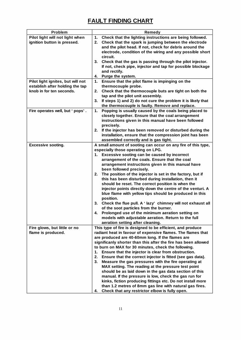
FAULT FINDING CHART
Problem RemedyPilot light will not light whenignition button is pressed.
1. Check that the lighting instructions are being followed.2. Check that the spark is jumping between the electrode
and the pilot head. If not, check for debris around theelectrode, condition of the wiring and any possible shortcircuit.
3. Check that the gas is passing through the pilot injector.If not, check pipe, injector and tap for possible blockageand rectify.
4. Purge the system.Pilot light ignites, but will notestablish after holding the tapknob in for ten seconds.
1. Ensure that the pilot flame is impinging on thethermocouple probe.
2. Check that the thermocouple buts are tight on both thetap and the pilot unit assembly.
3. If steps 1) and 2) do not cure the problem it is likely thatthe thermocouple is faulty. Remove and replace.
Fire operates well, but ‘pops’. 1. Popping is usually caused by the coals being placed toclosely together. Ensure that the coal arrangementinstructions given in this manual have been followedprecisely.
2. If the injector has been removed or disturbed during theinstallation, ensure that the compression joint has beenassembled correctly and is gas tight.
Excessive sooting. A small amount of sooting can occur on any fire of this type,especially those operating on LPG.1. Excessive sooting can be caused by incorrect
arrangement of the coals. Ensure that the coalarrangement instructions given in this manual havebeen followed precisely.
2. The position of the injector is set in the factory, but ifthis has been disturbed during installation, then itshould be reset. The correct position is when theinjector points directly down the centre of the venturi. Ablue flame with yellow tips should be produced in thisposition.
3. Check the flue pull. A ‘lazy’ chimney will not exhaust allof the soot particles from the burner.
4. Prolonged use of the minimum aeration setting onmodels with adjustable aeration. Return to the fullaeration setting after cleaning.
Fire glows, but little or noflame is produced.
This type of fire is designed to be efficient, and produceradiant heat in favour of expensive flames. The flames thatare produced are 40-60mm long. If the flames aresignificanly shorter than this after the fire has been allowedto burn on MAX for 30 minutes, check the following.1. Ensure that the injector is clear from obstruction.2. Ensure that the correct injector is fitted (see gas data).3. Measure the gas pressures with the fire operating at
MAX setting. The reading at the pressure test pointshould be as laid down in the gas data section of thismanual. If the pressure is low, check the gas run forkinks, fiction producing fittings etc. Do not install morethan 1.2 metres of 8mm gas line with natural gas fires.
4. Check that any restrictor elbow is fully open.
12
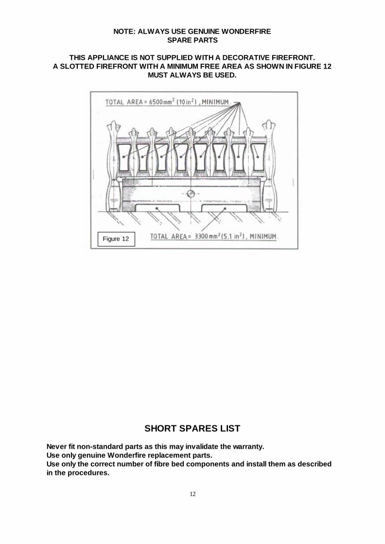
NOTE: ALWAYS USE GENUINE WONDERFIRESPARE PARTS
THIS APPLIANCE IS NOT SUPPLIED WITH A DECORATIVE FIREFRONT.A SLOTTED FIREFRONT WITH A MINIMUM FREE AREA AS SHOWN IN FIGURE 12
MUST ALWAYS BE USED.
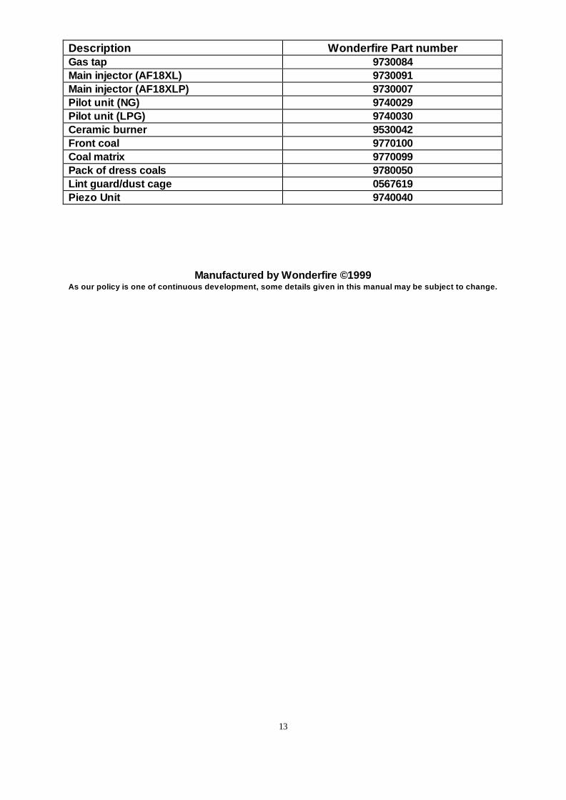
SHORT SPARES LIST
Never fit non-standard parts as this may invalidate the warranty.Use only genuine Wonderfire replacement parts.Use only the correct number of fibre bed components and install them as describedin the procedures.
Figure 12
13
Description Wonderfire Part numberGas tap 9730084Main injector (AF18XL) 9730091Main injector (AF18XLP) 9730007Pilot unit (NG) 9740029Pilot unit (LPG) 9740030Ceramic burner 9530042Front coal 9770100Coal matrix 9770099Pack of dress coals 9780050Lint guard/dust cage 0567619Piezo Unit 9740040
Manufactured by Wonderfire ©1999As our policy is one of continuous development, some details given in this manual may be subject to change.


![(5) C n & Excel Excel 7 v) Excel Excel 7 )Þ77 Excel Excel ... · (5) C n & Excel Excel 7 v) Excel Excel 7 )Þ77 Excel Excel Excel 3 97 l) 70 1900 r-kž 1937 (filllß)_] 136.8cm 136.8cm](https://img.pdfslide.us/doc/110x75/5f71a890b98d435cfa116d55/5-c-n-excel-excel-7-v-excel-excel-7-77-excel-excel-5-c-n-.jpg)