Embed Size (px)
Citation preview
Airfield Lighting
Manual
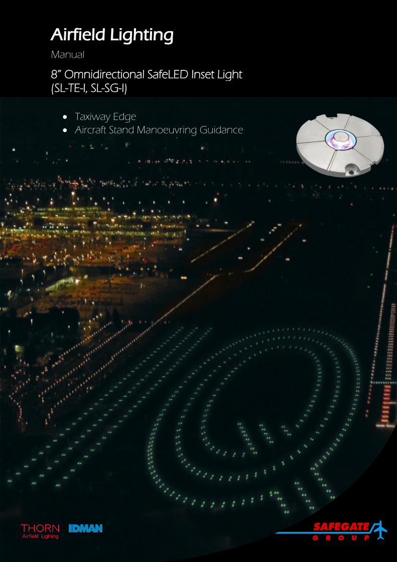
8” Omnidirectional SafeLED Inset Light (SL-TE-I, SL-SG-I)
Taxiway Edge
Aircraft Stand Manoeuvring Guidance

Note: This page is blank for convenient double-sided printing.
Airfield Lighting Safegate Group Manual Date: September 2014 Ref: SL-TE-I, SL-SG-I Version: 1.4
Page 1 of 16
MANUAL
8” OMNIDIRECTIONAL SAFELED INSET LIGHT
(SL-TE-I, SL-SG-I)
CONTENTS
Section Description Page No.
1. INTRODUCTION ........................................................................................................... 3
1.1 SAFETY INSTRUCTIONS ................................................................................ 3
1.2 DESCRIPTION OF THE FITTING .................................................................... 4
1.1 DELIVERY OF THE FITTING ........................................................................... 4
2. INSTALLATION ............................................................................................................. 5
2.1 INSTALLING/ REMOVING THE FITTING ........................................................ 6
3. MAINTENANCE ............................................................................................................ 7
3.1 BASIC MAINTENANCE PROGRAMME ........................................................... 7
3.2 WORKSHOP MAINTENANCE ......................................................................... 8
4. SUPPORT .................................................................................................................... 13
4.1 SAFEGATE GROUP WEBSITE ..................................................................... 13
4.2 RE-CYCLING .................................................................................................. 14
4.3 SPARE PARTS ............................................................................................... 14
Airfield Lighting Safegate Group Manual Date: September 2014 Ref: SL-TE-I, SL-SG-I Version: 1.4
Page 2 of 16
Documentation
This document includes Airfield Lighting information with a focus on safety, installation and maintenance procedures.
For more information, see www.safegate.com.
Note: It is very important to read this document before any work is started.
Copyright
© Copyright 2013 by Safegate Group. All rights reserved. This item and the information contained herein are the property of Safegate Group. No part of this document may be reproduced, transmitted, transcribed, stored in a retrieval system, or translated into any language or computer language in any form or by any means otherwise, without the expressed written permission of Safegate Group, Djurhagegatan 19, SE-213 76 Malmö, Sweden.
History
Version Date Description
1.0 October 2010 First Release
1.1 October 2011 Second Release
1.2 January 2013 Third Release
1.3 March 2014 Fourth Release
1.4 August 2014 Fifth Release
Note: This page is to be updated with every authorised change to the document.
Abbreviations and Terms
This document may include abbreviations and terms.
Abbreviation Term
ASP-SC Airfield Smart Power SafeControl
A-SMGCS Advanced Surface Movement Guidance and Control System
CAA Civil Aviation Authority
CCR Constant Current Regulator
FAA Federal Aviation Administration
ICAO International Civil Aviation Organization
IEC International Electrotechnical Committee
LED Light Emitting Diode
LMS Light Monitor and Switch unit
NATO North Atlantic Treaty Organization
NCU Network Concentrator Unit
OMNI Omni-directional fitting
SCF Series Circuit Filter
SCM Series Circuit Modem
SMGCS Surface Movement Guidance and Control System
SSU System Switch Unit
STAC Service Technique de l'Aviation Civile (France)
STANAG Standardization Agreement (NATO)
Airfield Lighting Safegate Group Manual Date: September 2014 Ref: SL-TE-I, SL-SG-I Version: 1.4
Page 3 of 16
1. INTRODUCTION
In this section you can find a general description and safety instructions related to the installation and usage of the fitting.
The SafeLED TE-I is an omnidirectional LED inset light. The light is available in two versions: for connection in a series circuit or for connection in a parallel system.
The SafeLED light has integrated fail open technology which means that the CCR can detect any failure in the LED or the electronics. The LED light follows the same light intensity curve as a corresponding halogen lamp with different intensity levels at the CCR. This means that the fitting is fully backwards compatible with a halogen lamp fitting.
Note: Integrated fail open and light intensity control is only available for the series circuit version.
1.1 SAFETY INSTRUCTIONS
Make sure you read this section and are familiar with safety precautions before any work is started.
Product Safety
Airfield lighting fixtures in a constant current circuits are connected in a circuit via isolating transformers with currents between 2.0 – 6.6A in the primary circuits. The primary voltages, depending on the circuitry, are usually several kilovolts and therefore lethal. Although the open circuit voltages of the isolating transformers are much lower, the peak voltage while opening the secondary circuit under current is also hazardous. So it is vitally important to follow all the safety regulations with adequate circumspection.
In the design of this equipment all the practical safety aspects have been taken into account. It is also important to strictly follow existing international or national regulations, the instructions established by civil aviation authority or airport operator and the following instructions.
Electrical Maintenance
Valid safety regulations must always be followed. Never carry out any maintenance or maintenance measures before the current is confirmed as safely disconnected. Use extreme caution when disconnecting or connecting high voltage primary connectors.
WARNING! PRIOR TO THE COMMENCEMENT OF WORK ALL ELECTRICAL SERVICES MUST BE ISOLATED FROM THE SUPPLY AND CONNECTED TO EARTH. FULL DETAILS OF THE WORK INVOLVED MUST BE GIVEN TO THE AUTHORISED PERSON RESPONSIBLE FOR THE ELECTRICAL ENGINEERING SERVICES AT THE AIRPORT WITH REGARD TO THE DURATION OF THE WORK AND SO ON. IT IS RECOMMENDED THAT PRIOR TO STARTING ANY CUTTING WORK, THE NATURE AND LOCATION OF SERVICES SUCH AS CABLE DUCTS AND THE LIKE SHOULD BE IDENTIFIED. ANY INSTALLATION OR MAINTENANCE WORK SHOULD ONLY BE CARRIED OUT BY TRAINED AND EXPERIENCED PERSONNEL. ALSO, WHEN WORKING ON CIRCUITS USING AIRFIELD SMART POWER SYSTEM (ASP) THE SCM MUST BE TUNED OFF.
Airfield Lighting Safegate Group Manual Date: September 2014 Ref: SL-TE-I, SL-SG-I Version: 1.4
Page 4 of 16
Mechanical Maintenance
When maintaining mechanical components, it is important to follow the instructions for electrical maintenance.
1.2 DESCRIPTION OF THE FITTING
The inset light is an 8” omnidirectional low projection inset LED light provided with a blue LED.
The fitting can be installed in standard bases or with adapter rings in an existing/new airfield lighting system.
1.1 DELIVERY OF THE FITTING
The fittings are ready for installation, each unit supplied completely assembled, tested and sealed. The electrical connection is with one secondary cable to a transformer, the cable is equipped with an FAA L-823 plug (style 6) for the 6.6A version or with an Amphenol S44 (style 3) plug for the VAC version.
Each unit is individually packed in a durable, cushioned and corrugated cardboard box, labelled with its reference name and code.
For more information, see www.safegate.com.
Airfield Lighting Safegate Group Manual Date: September 2014 Ref: SL-TE-I, SL-SG-I Version: 1.4
Page 5 of 16
2. INSTALLATION
In this section you can find a description of the different steps for successful installation of the fitting. Before you start, make sure you have read and understand §1.1 Safety Instructions.
When removing the fitting from its packaging box, check that nothing is broken.
The screw tapping of the frangible support can be either 2 in. NPS (American standard - 11.5 threads per inch) or 2 in. BPS (British standard - 11 threads per inch). Check support and base tapings fit.
The following tools and accessories are required for installation and removal of the unit:
Standard tools and accessories:
One Box spanner 16 mm (for installation in standard Thorn bases) or for example (non-standard Thorn AFL) 17mm, 3/8" UNC.
One torque wench with a 16mm adaptor.
Two big screwdrivers for removal.
One brush or cloth.
Note: Provided that the base intended to receive the fitting has been properly installed, no other specific tool is required.
The installation steps refer to:
1. Installing/removing the fitting
Airfield Lighting Safegate Group Manual Date: September 2014 Ref: SL-TE-I, SL-SG-I Version: 1.4
Page 6 of 16
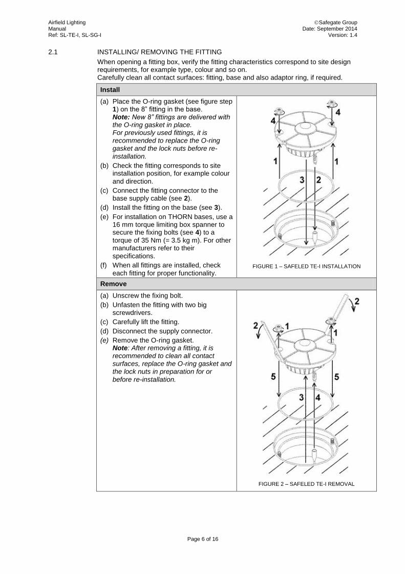
2.1 INSTALLING/ REMOVING THE FITTING
When opening a fitting box, verify the fitting characteristics correspond to site design requirements, for example type, colour and so on. Carefully clean all contact surfaces: fitting, base and also adaptor ring, if required.
Install
(a) Place the O-ring gasket (see figure step 1) on the 8” fitting in the base. Note: New 8” fittings are delivered with the O-ring gasket in place. For previously used fittings, it is recommended to replace the O-ring gasket and the lock nuts before re-installation.
(b) Check the fitting corresponds to site installation position, for example colour and direction.
(c) Connect the fitting connector to the base supply cable (see 2).
(d) Install the fitting on the base (see 3).
(e) For installation on THORN bases, use a 16 mm torque limiting box spanner to secure the fixing bolts (see 4) to a torque of 35 Nm (= 3.5 kg m). For other manufacturers refer to their specifications.
(f) When all fittings are installed, check each fitting for proper functionality.
FIGURE 1 – SAFELED TE-I INSTALLATION
Remove
(a) Unscrew the fixing bolt.
(b) Unfasten the fitting with two big screwdrivers.
(c) Carefully lift the fitting.
(d) Disconnect the supply connector.
(e) Remove the O-ring gasket. Note: After removing a fitting, it is recommended to clean all contact surfaces, replace the O-ring gasket and the lock nuts in preparation for or before re-installation.
FIGURE 2 – SAFELED TE-I REMOVAL
Airfield Lighting Safegate Group Manual Date: September 2014 Ref: SL-TE-I, SL-SG-I Version: 1.4
Page 7 of 16
3. MAINTENANCE
In this section you can find a description of the different steps for the maintenance of the fitting.
Before you start, make sure you have read and understand §1.1 Safety Instructions.
Find out the location of the light unit that needs maintenance. If the purpose is to replace an existing light unit with new one, make sure that corresponding unit is available.
WARNING! WHEN A FITTING HAS BEEN REMOVED FROM ITS BASE, THE BASE MUST BE EITHER FITTED WITH A COVER OR A RESERVE FITTING PUT IN ITS PLACE.
IT IS RECOMMENDED THAT ONLY AUTORIZED PERSONNEL DISASSEMBLE FITTINGS WITH PRIOR AGREEMENT FROM SAFEGATE.
3.1 BASIC MAINTENANCE PROGRAMME
There are recommended maintenance tasks to ensure that the equipment is in correct operating condition.
Maintenance tasks
Weekly Visual inspection of the fitting.
Removal of dust from external surfaces of the fitting.
Monthly Check of the optical window, check for mechanical damage.
Check for proper fixing of the fitting in its base.
Yearly Detailed inspection of the fitting.
Check of the body resistance, check for mechanical damage (for example cracks around prism windows).
Clean of the optical windows.
A daily function check is referred to in the document: ICAO, Airport Services Manual Part 9, Airport Maintenance Practice and FAA AC 150/5340-26A, Maintenance of airport visual aids facilities.
The light is designed for outdoor operation, however storing the light outside without using it is a risk for damage to light components. For a longer storage time (more than a week), it is recommended to store the light indoors in a dry and dust free environment and at room temperature. Proper storage ensures trouble free replacement procedures. It is strongly recommended not to store any electrical equipment outside.
Note: Only the most common maintenance procedures are instructed in following paragraphs. Construction of the luminaire allows that it can be fully disassembled and all the parts can be replaced if needed.
Airfield Lighting Safegate Group Manual Date: September 2014 Ref: SL-TE-I, SL-SG-I Version: 1.4
Page 8 of 16
3.2 WORKSHOP MAINTENANCE
Before you start, make sure you have read and understand §1.1 Safety Instructions.
The following tools and accessories are required for installation and removal of the unit:
One angled socket spanner of 7 mm (wiring cover).
One angled socket spanner of 10 mm (housing).
One angled socket spanner of 16 mm (standard Thorn AFL base installation).
One Torque limiting spanner with 16 mm, 10mm, 5 mm adaptors.
One 5 mm Allen key (LED board holder screws).
One angled socket spanner of 22 mm (VAC converter cable gasket nut).
Two large flat blade screwdrivers (base removal).
Silicone grease (housing screws).
One angled socket spanner of 12 mm (valve water-tightness)
Special sealing compound (valve water-tightness).
One brush or cloth (general cleaning).
Note: A compressor (or a manual car tyre pump) equipped with a manometer is required to check the fitting for water-tightness.
The workshop maintenance refers to following:
1. Disassembling/ assembling the fitting
2. Checking the fitting for water tightness
3. Replacing a LED assembly with holder
4. Replacing a prism and its gasket
5. Replacing a 230V or VAC converter
Airfield Lighting Safegate Group Manual Date: September 2014 Ref: SL-TE-I, SL-SG-I Version: 1.4
Page 9 of 16
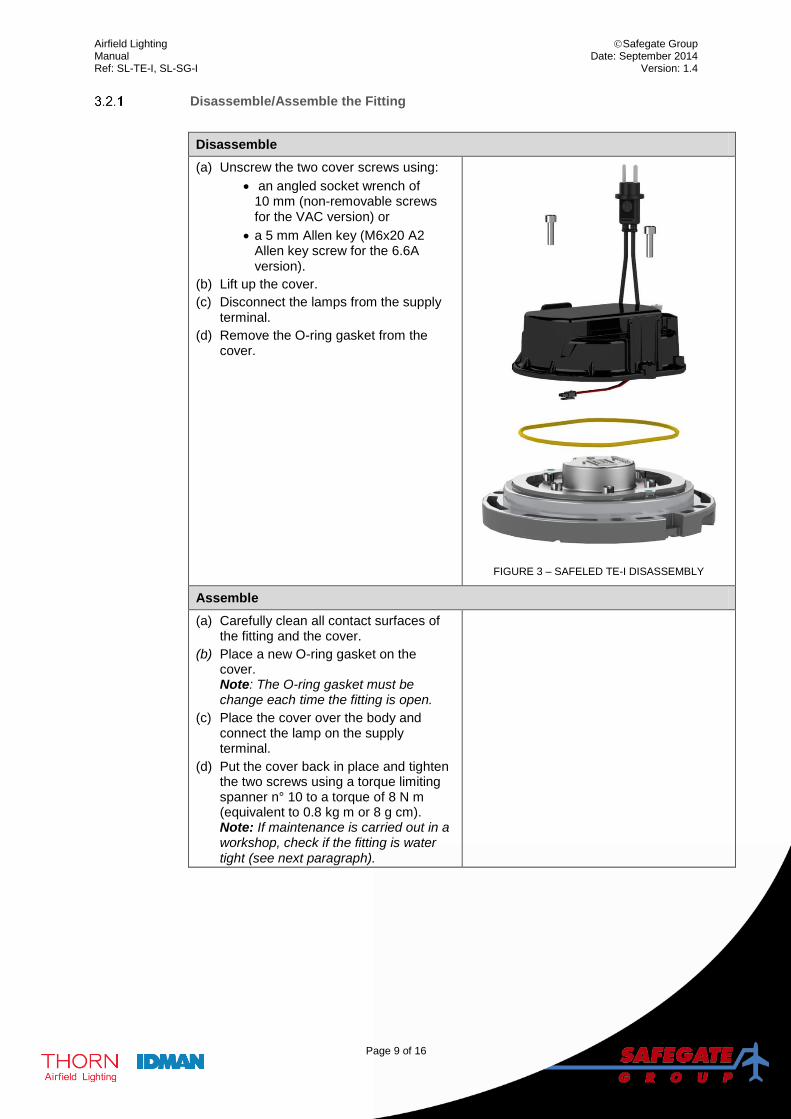
Disassemble/Assemble the Fitting
Disassemble
(a) Unscrew the two cover screws using:
an angled socket wrench of 10 mm (non-removable screws for the VAC version) or
a 5 mm Allen key (M6x20 A2 Allen key screw for the 6.6A version).
(b) Lift up the cover.
(c) Disconnect the lamps from the supply terminal.
(d) Remove the O-ring gasket from the cover.
FIGURE 3 – SAFELED TE-I DISASSEMBLY
Assemble
(a) Carefully clean all contact surfaces of the fitting and the cover.
(b) Place a new O-ring gasket on the cover. Note: The O-ring gasket must be change each time the fitting is open.
(c) Place the cover over the body and connect the lamp on the supply terminal.
(d) Put the cover back in place and tighten the two screws using a torque limiting spanner n° 10 to a torque of 8 N m (equivalent to 0.8 kg m or 8 g cm). Note: If maintenance is carried out in a workshop, check if the fitting is water tight (see next paragraph).
Airfield Lighting Safegate Group Manual Date: September 2014 Ref: SL-TE-I, SL-SG-I Version: 1.4
Page 10 of 16
Checking the Fitting for Water-Tightness
If maintenance is carried out in a workshop, always check if the fitting is water tight, after disassembly/assembly, before installation in the field.
(a) Remove the Water-tightness test valve cap.
(b) Fill up the fitting with compressed air (test pressure = 130 kPa).
(c) Put the fitting in water wait 3 minutes, and check if air leaks out of the fitting.
- If air leaks out of the fitting (between housing and top plate or between prism and top plate or water-tightness valve and top plate), the fitting is not watertight and must be repaired. Release the air from the fitting. Disassemble the fitting and re-check the mating surfaces and gaskets. Assemble the fitting and perform the water-tightness test again.
+ If the fixture is water tight, release the compressed air from the fitting and replace the cap on the test valve.
(d) The fitting is ready to reinstall in the field.
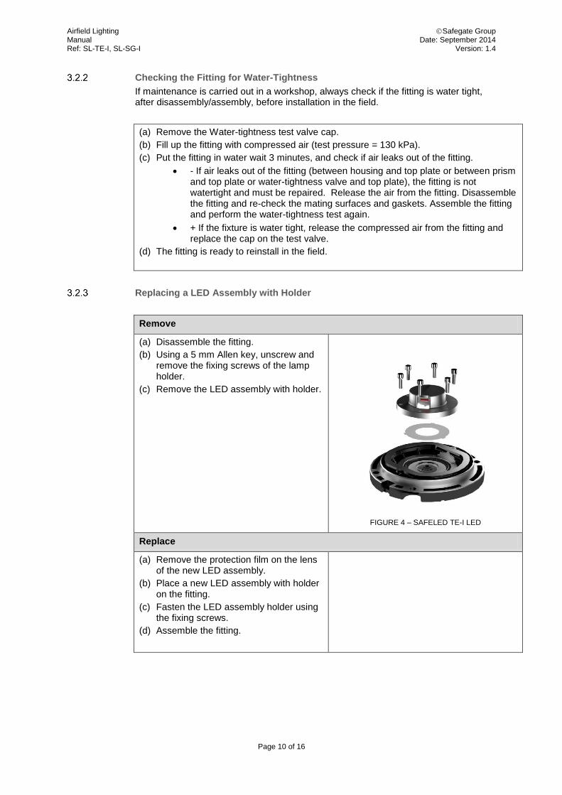
Replacing a LED Assembly with Holder
Remove
(a) Disassemble the fitting.
(b) Using a 5 mm Allen key, unscrew and remove the fixing screws of the lamp holder.
(c) Remove the LED assembly with holder.
FIGURE 4 – SAFELED TE-I LED
Replace
(a) Remove the protection film on the lens of the new LED assembly.
(b) Place a new LED assembly with holder on the fitting.
(c) Fasten the LED assembly holder using the fixing screws.
(d) Assemble the fitting.
Airfield Lighting Safegate Group Manual Date: September 2014 Ref: SL-TE-I, SL-SG-I Version: 1.4
Page 11 of 16
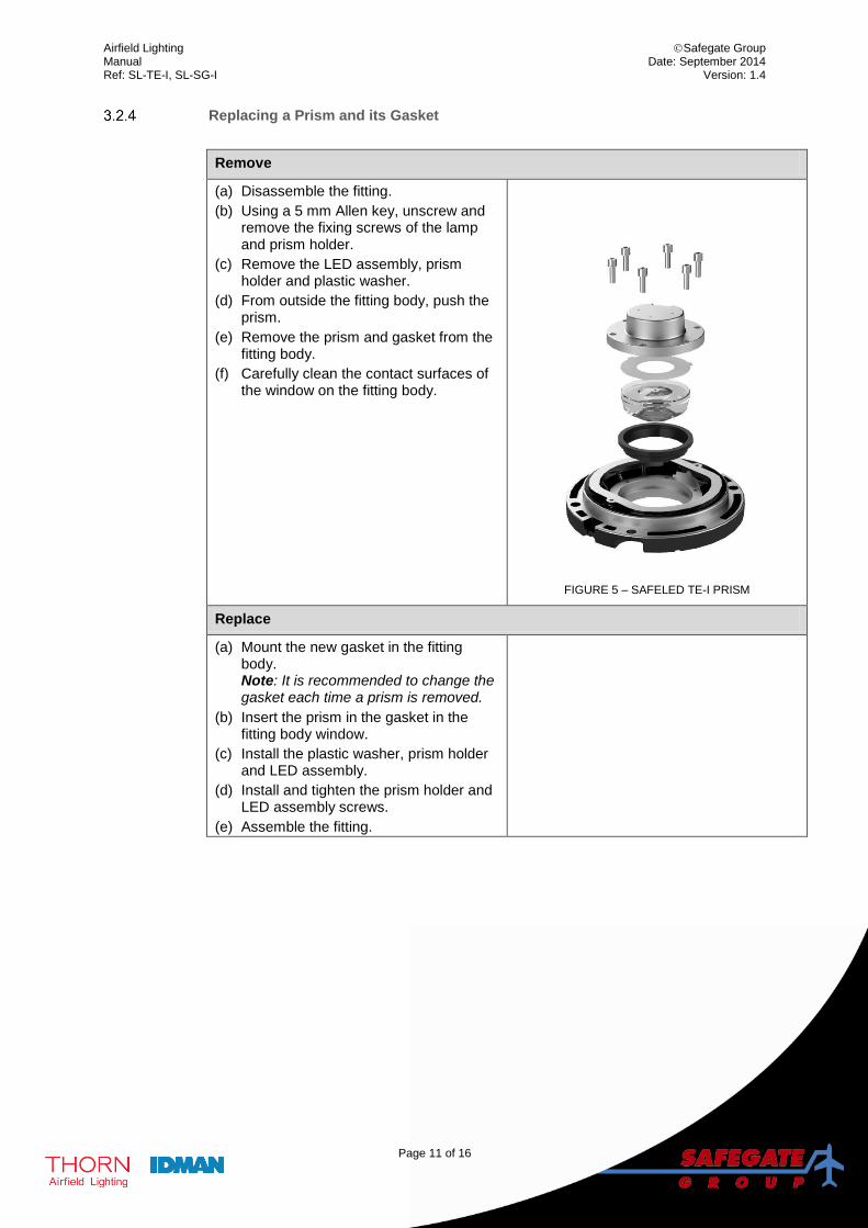
Replacing a Prism and its Gasket
Remove
(a) Disassemble the fitting.
(b) Using a 5 mm Allen key, unscrew and remove the fixing screws of the lamp and prism holder.
(c) Remove the LED assembly, prism holder and plastic washer.
(d) From outside the fitting body, push the prism.
(e) Remove the prism and gasket from the fitting body.
(f) Carefully clean the contact surfaces of the window on the fitting body.
FIGURE 5 – SAFELED TE-I PRISM
Replace
(a) Mount the new gasket in the fitting body. Note: It is recommended to change the gasket each time a prism is removed.
(b) Insert the prism in the gasket in the fitting body window.
(c) Install the plastic washer, prism holder and LED assembly.
(d) Install and tighten the prism holder and LED assembly screws.
(e) Assemble the fitting.
Airfield Lighting Safegate Group Manual Date: September 2014 Ref: SL-TE-I, SL-SG-I Version: 1.4
Page 12 of 16
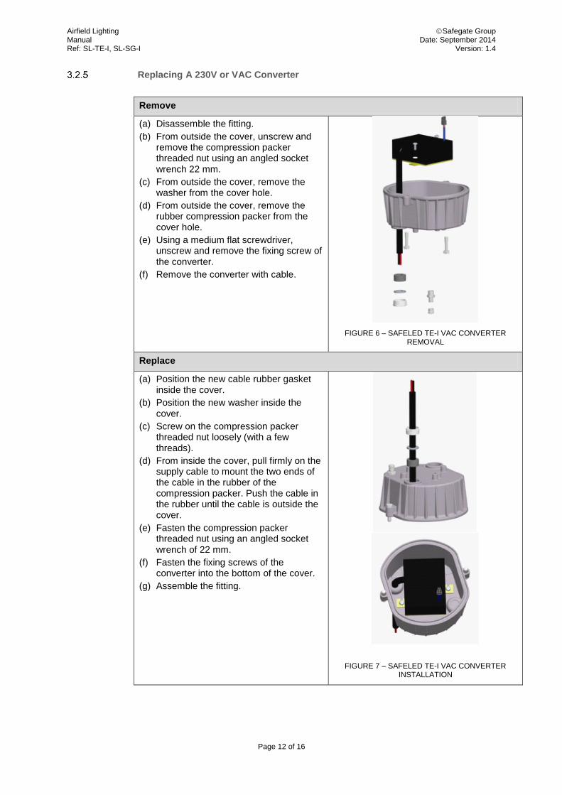
Replacing A 230V or VAC Converter
Remove
(a) Disassemble the fitting.
(b) From outside the cover, unscrew and remove the compression packer threaded nut using an angled socket wrench 22 mm.
(c) From outside the cover, remove the washer from the cover hole.
(d) From outside the cover, remove the rubber compression packer from the cover hole.
(e) Using a medium flat screwdriver, unscrew and remove the fixing screw of the converter.
(f) Remove the converter with cable.
FIGURE 6 – SAFELED TE-I VAC CONVERTER REMOVAL
Replace
(a) Position the new cable rubber gasket inside the cover.
(b) Position the new washer inside the cover.
(c) Screw on the compression packer threaded nut loosely (with a few threads).
(d) From inside the cover, pull firmly on the supply cable to mount the two ends of the cable in the rubber of the compression packer. Push the cable in the rubber until the cable is outside the cover.
(e) Fasten the compression packer threaded nut using an angled socket wrench of 22 mm.
(f) Fasten the fixing screws of the converter into the bottom of the cover.
(g) Assemble the fitting.
FIGURE 7 – SAFELED TE-I VAC CONVERTER INSTALLATION
Airfield Lighting Safegate Group Manual Date: September 2014 Ref: SL-TE-I, SL-SG-I Version: 1.4
Page 13 of 16
4. SUPPORT
Our experienced engineers are available for support and service at all times, 24 hour/7 days a week. They are part of a dynamic organization making sure the entire Safegate Group is committed to minimal disturbance for airport operations.
Safegate Group Support
Safegate Group knows that our equipment is used in one of the busiest industries in the world, where down-time costs money and creates delays for airlines and their passengers. As one of the world’s leading suppliers of airport systems, Safegate Group is committed to ensuring that our customers are able to get the most out of your equipment, regardless of the location or the time of day. For this reason, Safegate Group has established the Safegate Group Support service.
Safegate Group Support is a unique service provided by Safegate Group to our customers, free of charge during the warranty period or as a service contract. Any time of day, any day of the year, a Safegate Group engineer is on standby to answer questions and assist with any problems that may arise. Qualified technical assistance is just a phone call or an e-mail away, 24-7 worldwide.
+46 40 699 1740
4.1 SAFEGATE GROUP WEBSITE
The Safegate Group Website, www.safegate.com, offers information regarding our airport solutions, products, company, news, links, downloads, references, contacts and more. Note: There is also a Client/Partner login area for the latest information and updates, if available.
Airfield Lighting Safegate Group Manual Date: September 2014 Ref: SL-TE-I, SL-SG-I Version: 1.4
Page 14 of 16
4.2 RE-CYCLING
Local Authority Re-cycling
The disposal of Safegate Group products is to be made at an applicable collection point for the recycling of electrical and electronic equipment. The correct disposal of equipment prevents any potential negative consequences for the environment and human health, which could otherwise be caused by inappropriate waste handling. The recycling of materials helps to conserve natural resources. For more detailed information about recycling of products, contact your local authority city office.
Safegate Group Re-cycling
Safegate Group is fully committed to environmentally-conscious manufacturing with strict monitoring of our own processes as well as supplier components and sub-contractor operations. Safegate Group offers a re-cycling program for our products to all customers worldwide, whether or not the products were sold within the EU.
Safegate Group products and/or specific electrical and electronic component parts which are fully removed/separated from any customer equipment and returned will be accepted for our recycling program.
All items returned must be clearly labelled as follows:
For ROHS/WEEE Re-cycling
Sender contact information (Name, Business Address, Phone number).
Main Unit Serial Number.
Safegate Group will continue to monitor and update according for any future requirements for EU directives as and when EU member states implement new regulations and or amendments. It is our aim to maintain our compliance plan and assist our customers. Note: For more information, see www.safegate.com, or contact Safegate Group Support via email at [email protected] or phone +46 40 699 1740.
4.3 SPARE PARTS
Spare parts are available for Airfield Lightingfittings. For more information see the Spare Parts List document.
Note: Contact Safegate Group for assistance with ordering spare parts.
Airfield Lighting Safegate Group Manual Date: September 2014 Ref: SL-TE-I, SL-SG-I Version: 1.4
Page 15 of 16
Note: This page is blank for convenient double-sided printing.
Airfield Lighting Safegate Group Manual Date: September 2014 Ref: SL-TE-I, SL-SG-I Version: 1.4
Page 16 of 16
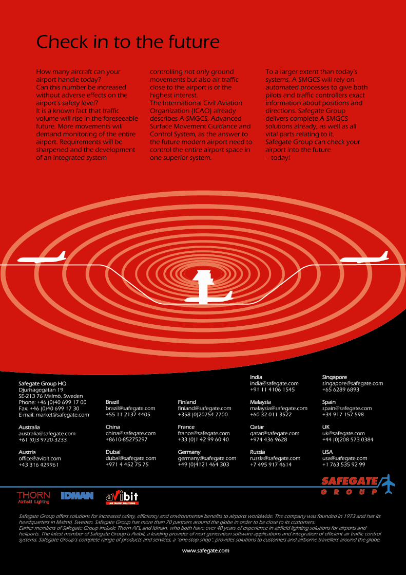
Check in to the future
How many aircraft can your
airport handle today? Can this number be increased without adverse effects on the airport’s safety level? It is a known fact that traffic volume will rise in the foreseeable future. More movements will demand monitoring of the entire airport. Requirements will be sharpened and the development
of an integrated system
controlling not only ground
movements but also air traffic close to the airport is of the highest interest. The International Civil Aviation Organization (ICAO) already describes A-SMGCS, Advanced Surface Movement Guidance and Control System, as the answer to the future modern airport need to control the entire airport space in
one superior system.
To a larger extent than today’s
systems, A-SMGCS will rely on automated processes to give both pilots and traffic controllers exact information about positions and directions. Safegate Group delivers complete A-SMGCS solutions already, as well as all vital parts relating to it. Safegate Group can check your airport into the future
– today!
www.safegate.com
Safegate Group offers solutions for increased safety, efficiency and environmental benefits to airports worldwide. The company was founded in 1973 and has its headquarters in Malmö, Sweden. Safegate Group has more than 70 partners around the globe in order to be close to its customers. Earlier members of Safegate Group include Thorn AFL and Idman, who both have over 40 years of experience in airfield lighting solutions for airports and heliports. The latest member of Safegate Group is Avibit, a leading provider of next generation software applications and integration of efficient air traffic control systems. Safegate Group’s complete range of products and services, a “one-stop shop”, provides solutions to customers and airborne travellers around the globe.
Safegate Group HQ Djurhagegatan 19 SE-213 76 Malmö, Sweden Phone: +46 (0)40 699 17 00 Fax: +46 (0)40 699 17 30 E-mail: [email protected] Australia [email protected] +61 (0)3 9720-3233 Austria [email protected] +43 316 429961
Brazil [email protected] +55 11 2137 4405 China [email protected] +8610-85275297 Dubai [email protected] +971 4 452 75 75
Finland [email protected] +358 (0)20754 7700 France [email protected] +33 (0)1 42 99 60 40 Germany [email protected] +49 (0)4121 464 303
India [email protected] +91 11 4106 1545 Malaysia [email protected] +60 32 011 3522 Qatar [email protected] +974 436 9628 Russia [email protected]
+7 495 917 4614
Singapore [email protected] +65 6289 6893 Spain [email protected] +34 917 157 598 UK [email protected] +44 (0)208 573 0384 USA [email protected] +1 763 535 92 99