Embed Size (px)
Citation preview
Aircraft Structural Aircraft Structural
ConsiderationsConsiderations
J.B.Rogers/Structures
Frank SauerFrank Sauer
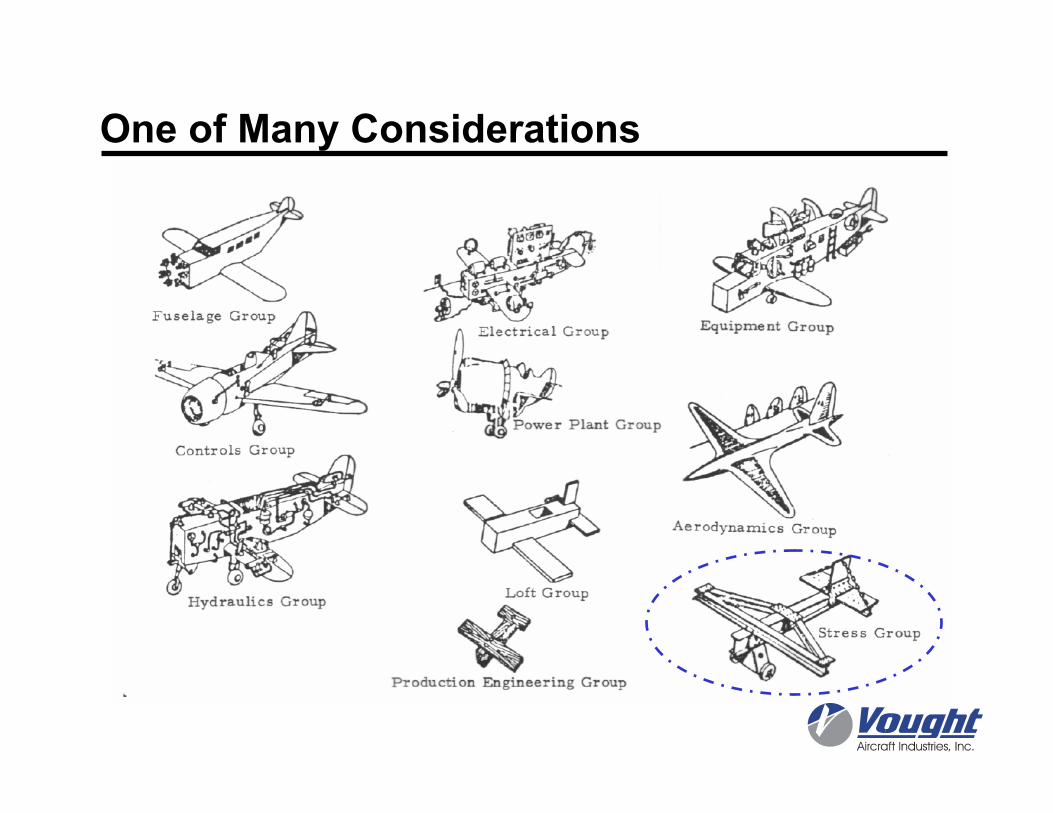
One of Many Considerations
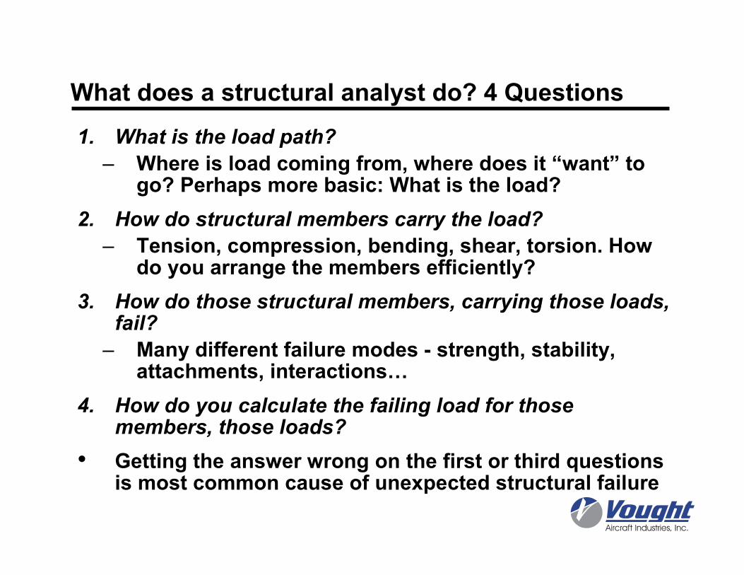
What does a structural analyst do? 4 Questions
1. What is the load path?
– Where is load coming from, where does it “want” to go? Perhaps more basic: What is the load?
2. How do structural members carry the load?
– Tension, compression, bending, shear, torsion. How do you arrange the members efficiently?
3. How do those structural members, carrying those loads, fail?
– Many different failure modes - strength, stability, attachments, interactions…
4. How do you calculate the failing load for those members, those loads?
• Getting the answer wrong on the first or third questions is most common cause of unexpected structural failure
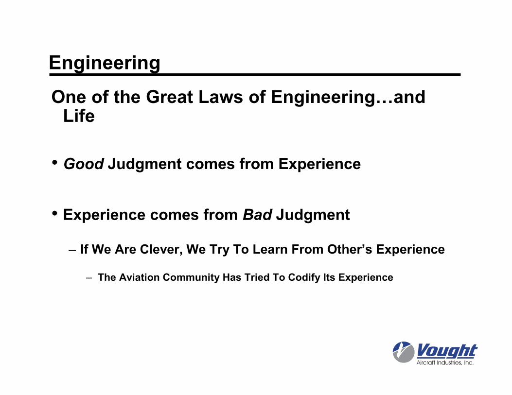
Engineering
One of the Great Laws of Engineering…and Life
• Good Judgment comes from Experience
• Experience comes from Bad Judgment
– If We Are Clever, We Try To Learn From Other’s Experience
– The Aviation Community Has Tried To Codify Its Experience
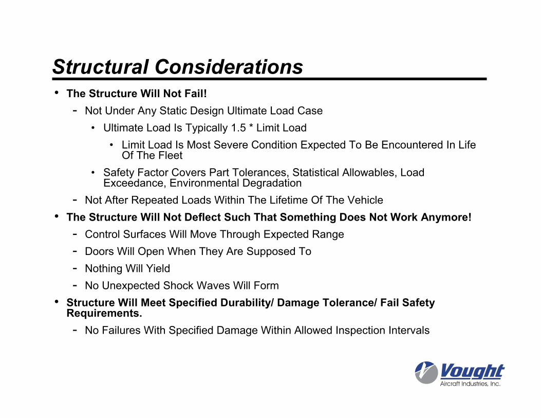
Structural Considerations• The Structure Will Not Fail!
- Not Under Any Static Design Ultimate Load Case
• Ultimate Load Is Typically 1.5 * Limit Load
• Limit Load Is Most Severe Condition Expected To Be Encountered In Life Of The Fleet
• Safety Factor Covers Part Tolerances, Statistical Allowables, Load Exceedance, Environmental Degradation
- Not After Repeated Loads Within The Lifetime Of The Vehicle
• The Structure Will Not Deflect Such That Something Does Not Work Anymore!
- Control Surfaces Will Move Through Expected Range
- Doors Will Open When They Are Supposed To
- Nothing Will Yield
- No Unexpected Shock Waves Will Form
• Structure Will Meet Specified Durability/ Damage Tolerance/ Fail Safety Requirements.
- No Failures With Specified Damage Within Allowed Inspection Intervals
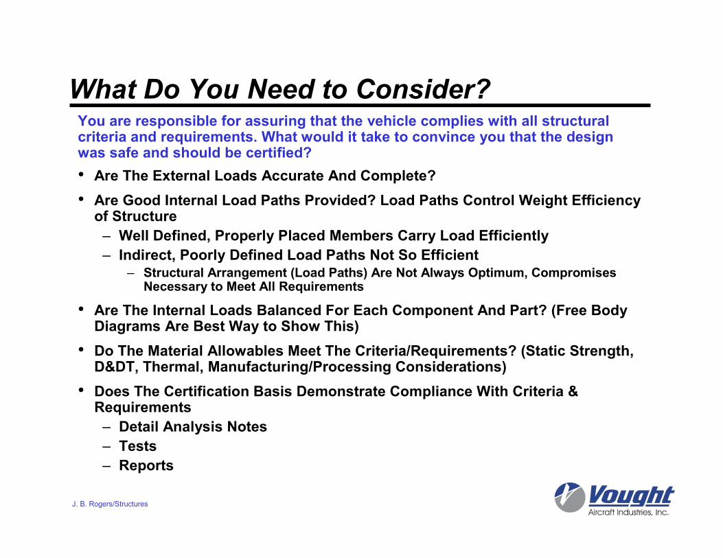
What Do You Need to Consider?
• Are The External Loads Accurate And Complete?
• Are Good Internal Load Paths Provided? Load Paths Control Weight Efficiency of Structure
– Well Defined, Properly Placed Members Carry Load Efficiently
– Indirect, Poorly Defined Load Paths Not So Efficient– Structural Arrangement (Load Paths) Are Not Always Optimum, Compromises
Necessary to Meet All Requirements
• Are The Internal Loads Balanced For Each Component And Part? (Free Body Diagrams Are Best Way to Show This)
• Do The Material Allowables Meet The Criteria/Requirements? (Static Strength, D&DT, Thermal, Manufacturing/Processing Considerations)
• Does The Certification Basis Demonstrate Compliance With Criteria & Requirements
– Detail Analysis Notes
– Tests
– Reports
J. B. Rogers/Structures
You are responsible for assuring that the vehicle complies with all structural criteria and requirements. What would it take to convince you that the design was safe and should be certified?
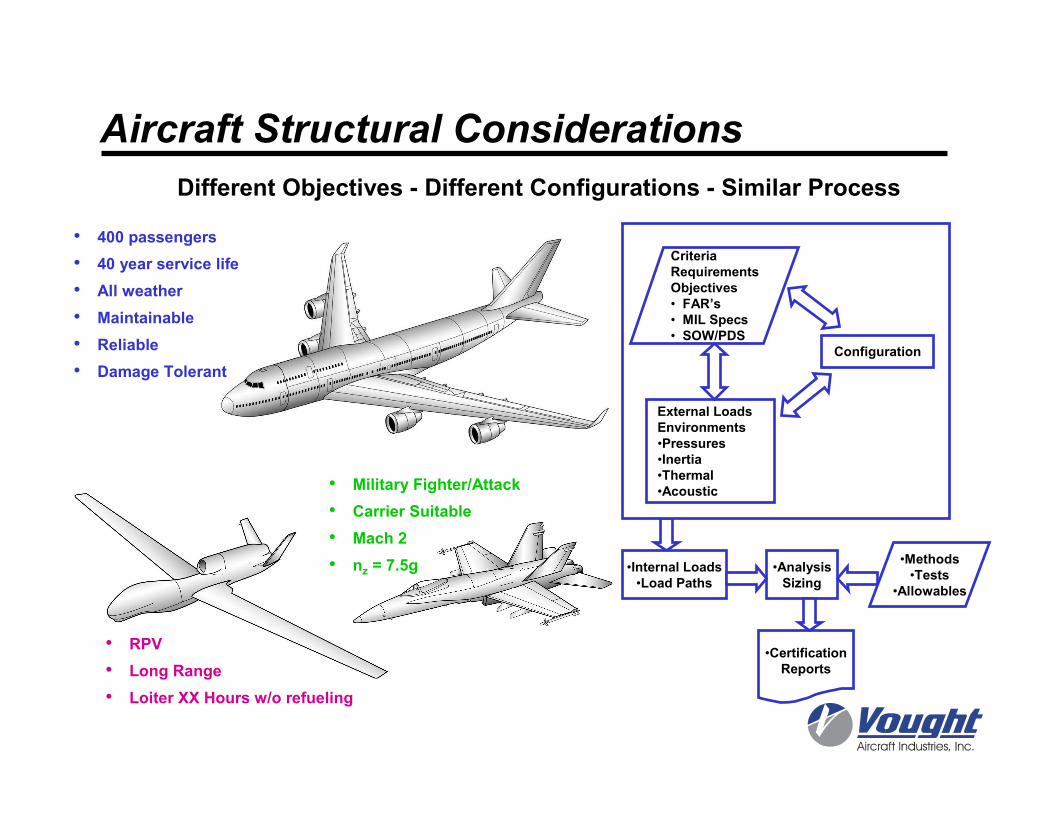
Different Objectives - Different Configurations - Similar Process
Aircraft Structural Considerations
•Internal Loads•Load Paths
•AnalysisSizing
CriteriaRequirementsObjectives• FAR’s• MIL Specs• SOW/PDS
Configuration
External LoadsEnvironments•Pressures•Inertia•Thermal•Acoustic
•Methods•Tests
•Allowables
•CertificationReports
• 400 passengers
• 40 year service life
• All weather
• Maintainable
• Reliable
• Damage Tolerant
• RPV
• Long Range
• Loiter XX Hours w/o refueling
• Military Fighter/Attack
• Carrier Suitable
• Mach 2
• nz = 7.5g
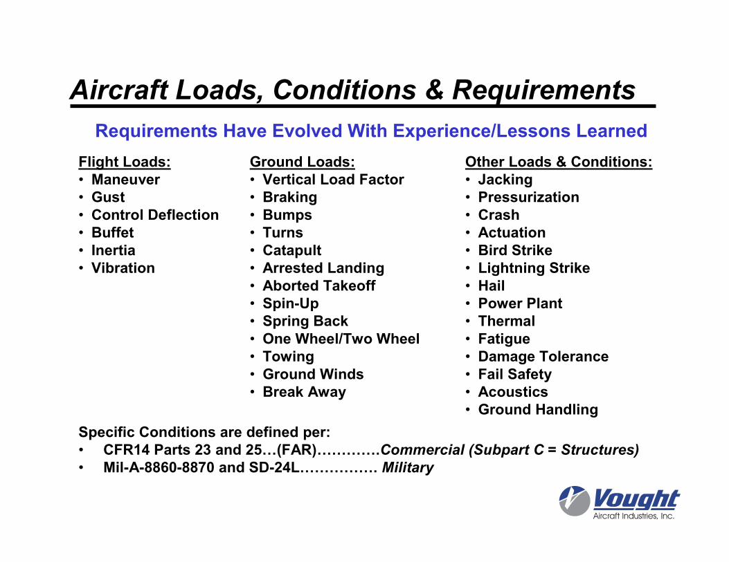
Aircraft Loads, Conditions & Requirements
Flight Loads:• Maneuver• Gust• Control Deflection• Buffet• Inertia• Vibration
Ground Loads:• Vertical Load Factor• Braking• Bumps• Turns• Catapult• Arrested Landing• Aborted Takeoff• Spin-Up• Spring Back• One Wheel/Two Wheel• Towing• Ground Winds• Break Away
Other Loads & Conditions:• Jacking• Pressurization• Crash• Actuation• Bird Strike• Lightning Strike• Hail• Power Plant• Thermal• Fatigue• Damage Tolerance• Fail Safety• Acoustics• Ground Handling
Specific Conditions are defined per:• CFR14 Parts 23 and 25…(FAR)………….Commercial (Subpart C = Structures)
• Mil-A-8860-8870 and SD-24L……………. Military
Requirements Have Evolved With Experience/Lessons Learned
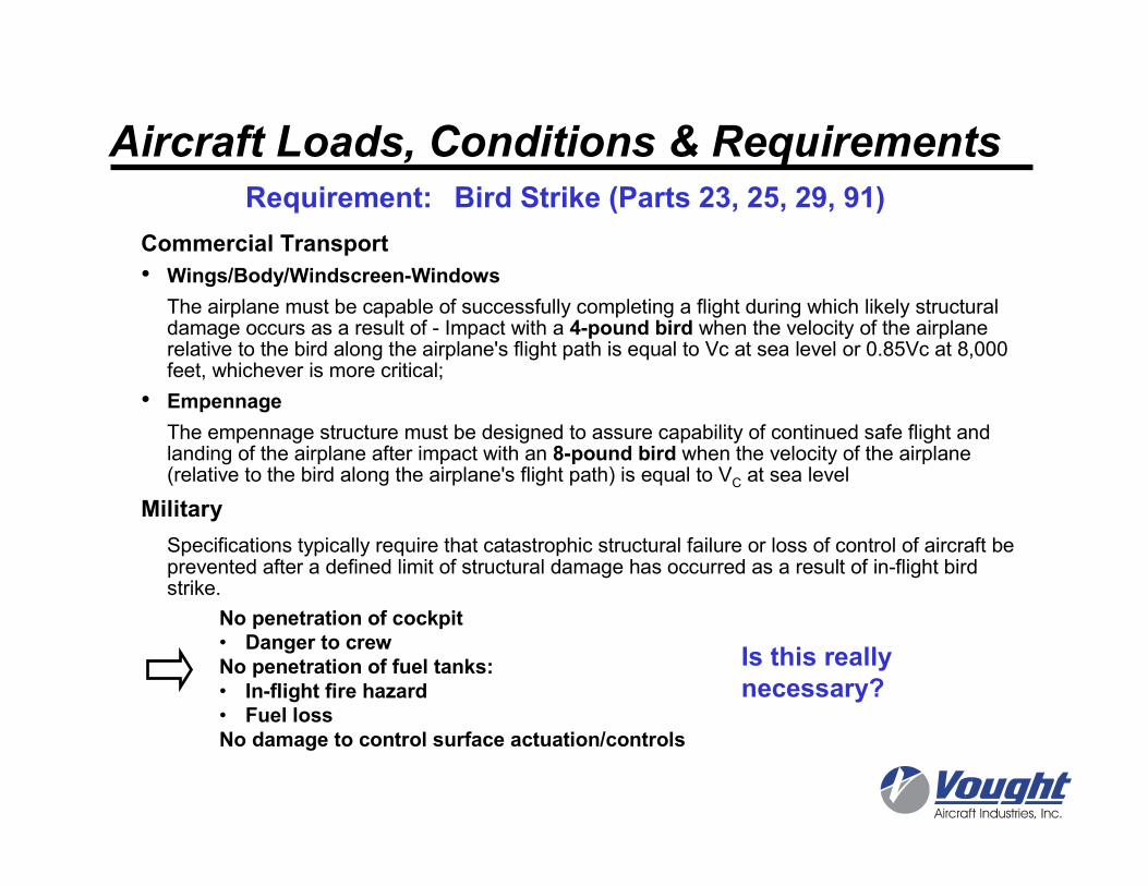
Commercial Transport
• Wings/Body/Windscreen-Windows
The airplane must be capable of successfully completing a flight during which likely structural damage occurs as a result of - Impact with a 4-pound bird when the velocity of the airplane relative to the bird along the airplane's flight path is equal to Vc at sea level or 0.85Vc at 8,000 feet, whichever is more critical;
• Empennage
The empennage structure must be designed to assure capability of continued safe flight and landing of the airplane after impact with an 8-pound bird when the velocity of the airplane (relative to the bird along the airplane's flight path) is equal to VC at sea level
Military
Specifications typically require that catastrophic structural failure or loss of control of aircraft be prevented after a defined limit of structural damage has occurred as a result of in-flight bird strike.
Requirement: Bird Strike (Parts 23, 25, 29, 91)
No penetration of cockpit• Danger to crewNo penetration of fuel tanks:• In-flight fire hazard• Fuel lossNo damage to control surface actuation/controls
Is this really necessary?
Aircraft Loads, Conditions & Requirements
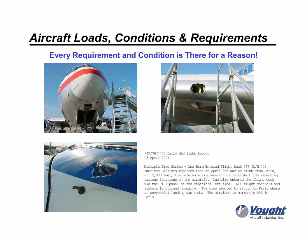
Every Requirement and Condition is There for a Reason!
747/767/777 Daily Highlight Report
03 April 2001
Multiple Bird Strike - One Bird Entered Flight Deck 767 (L/N 447)
American Airlines reported that on April 2nd during climb from Paris,
at 12,000 feet, the reference airplane struck multiple birds impacting
various locations on the aircraft. One bird entered the flight deck
via the P1-1 panel on the captain's left side. All flight controls and
systems functioned normally. The crew elected to return to Paris where
an uneventful landing was made. The airplane is currently AOG in
Paris.
Aircraft Loads, Conditions & Requirements
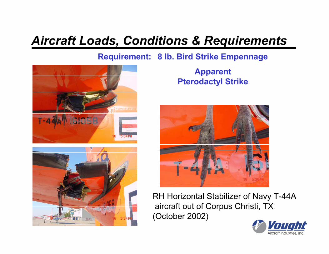
Aircraft Loads, Conditions & RequirementsRequirement: 8 lb. Bird Strike Empennage
ApparentPterodactyl Strike
RH Horizontal Stabilizer of Navy T-44A
aircraft out of Corpus Christi, TX
(October 2002)
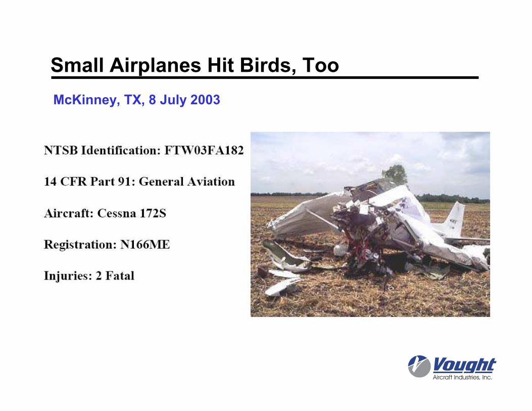
Small Airplanes Hit Birds, Too
McKinney, TX, 8 July 2003
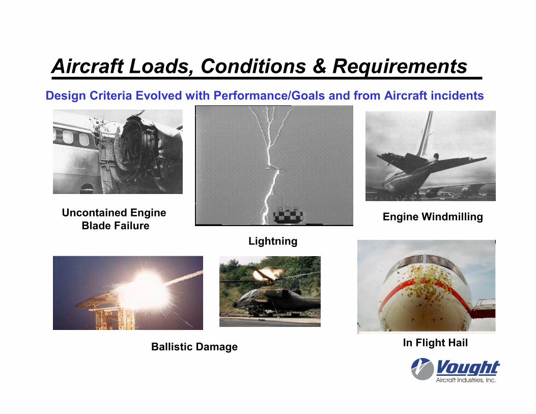
Design Criteria Evolved with Performance/Goals and from Aircraft incidents
Aircraft Loads, Conditions & Requirements
Uncontained Engine Blade Failure
Engine Windmilling
In Flight HailBallistic Damage
Lightning
Aircraft Loads, Conditions & Requirements
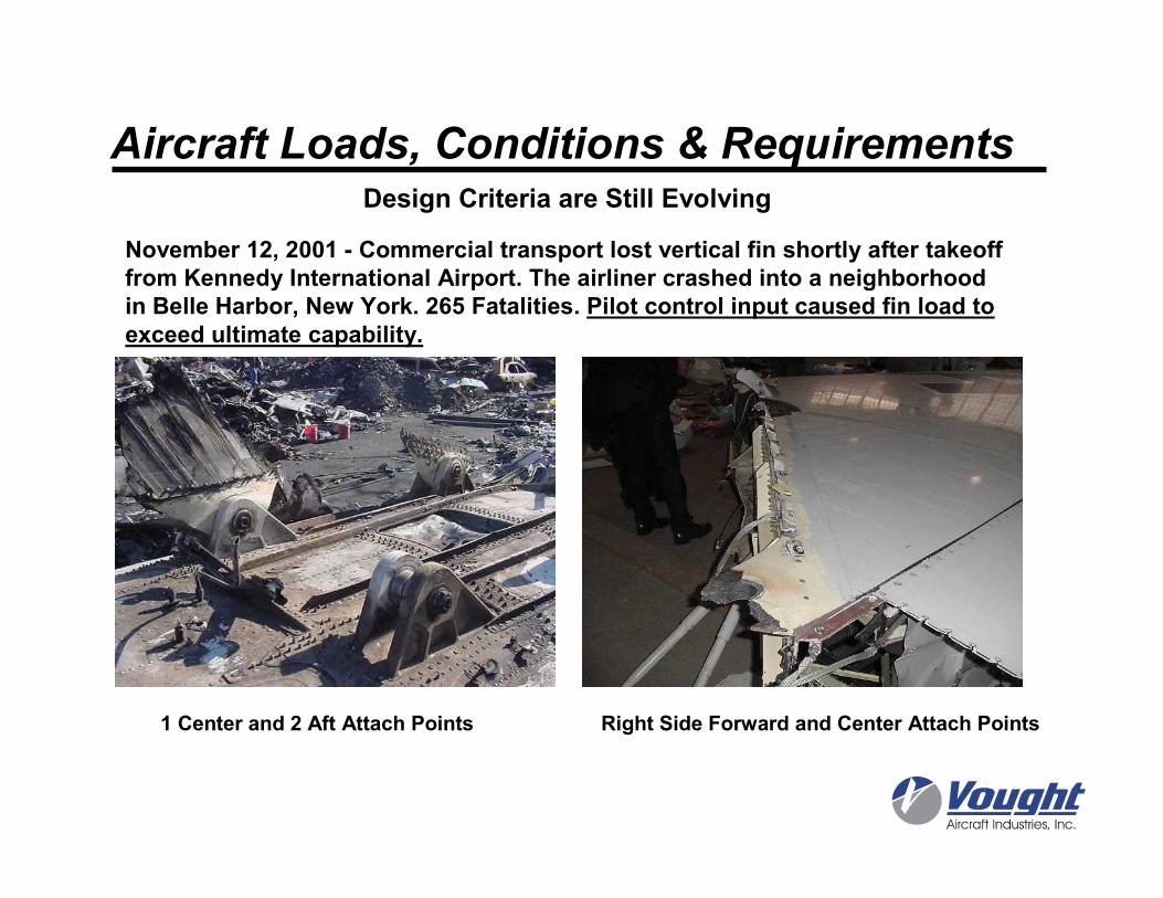
1 Center and 2 Aft Attach Points Right Side Forward and Center Attach Points
November 12, 2001 - Commercial transport lost vertical fin shortly after takeoff from Kennedy International Airport. The airliner crashed into a neighborhood in Belle Harbor, New York. 265 Fatalities. Pilot control input caused fin load to exceed ultimate capability.
Design Criteria are Still Evolving
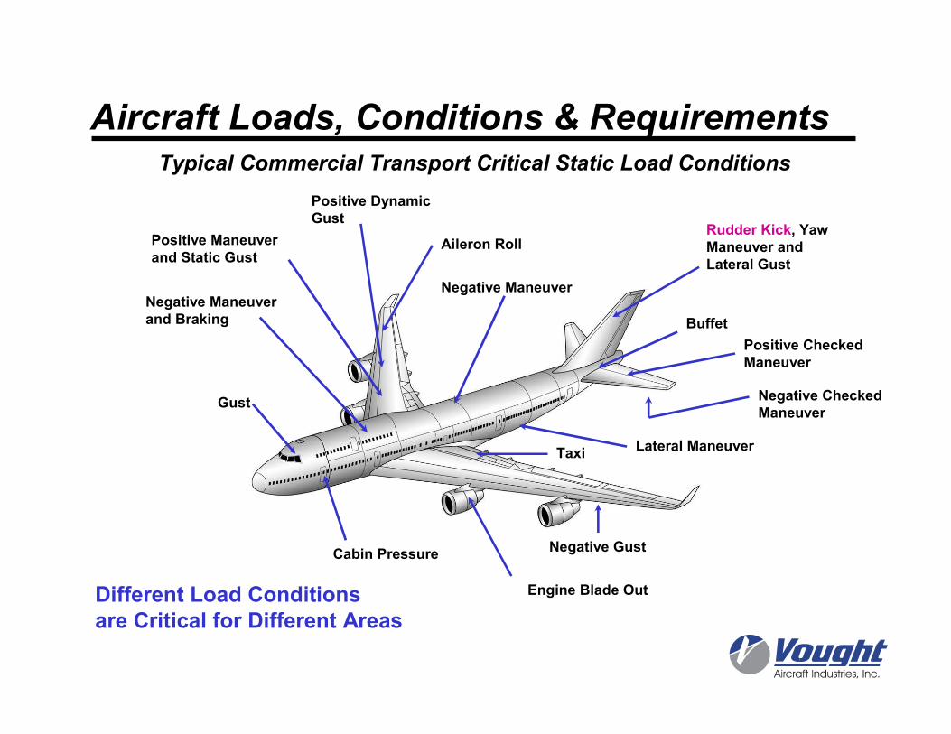
Rudder Kick, Yaw Maneuver andLateral Gust
Buffet
Positive CheckedManeuver
Negative CheckedManeuver
Negative Maneuver
Lateral Maneuver
Negative Gust
Engine Blade Out
Taxi
Negative Maneuverand Braking
Gust
Cabin Pressure
Aileron Roll
Positive DynamicGust
Positive Maneuverand Static Gust
Aircraft Loads, Conditions & Requirements
Different Load Conditionsare Critical for Different Areas
Typical Commercial Transport Critical Static Load Conditions
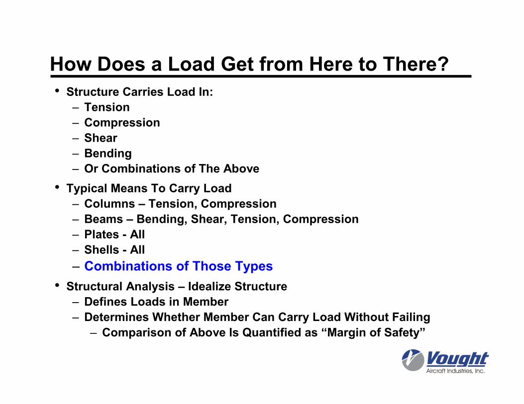
How Does a Load Get from Here to There?
• Structure Carries Load In:
– Tension
– Compression
– Shear
– Bending
– Or Combinations of The Above
• Typical Means To Carry Load
– Columns – Tension, Compression
– Beams – Bending, Shear, Tension, Compression
– Plates - All
– Shells - All
– Combinations of Those Types
• Structural Analysis – Idealize Structure
– Defines Loads in Member
– Determines Whether Member Can Carry Load Without Failing
– Comparison of Above Is Quantified as “Margin of Safety”
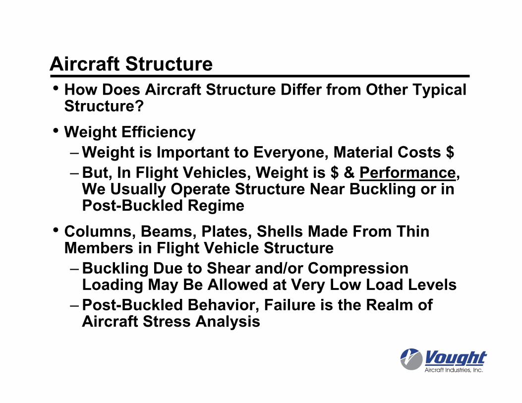
Aircraft Structure• How Does Aircraft Structure Differ from Other Typical Structure?
• Weight Efficiency
–Weight is Important to Everyone, Material Costs $
–But, In Flight Vehicles, Weight is $ & Performance, We Usually Operate Structure Near Buckling or in Post-Buckled Regime
• Columns, Beams, Plates, Shells Made From Thin Members in Flight Vehicle Structure
–Buckling Due to Shear and/or Compression Loading May Be Allowed at Very Low Load Levels
–Post-Buckled Behavior, Failure is the Realm of Aircraft Stress Analysis
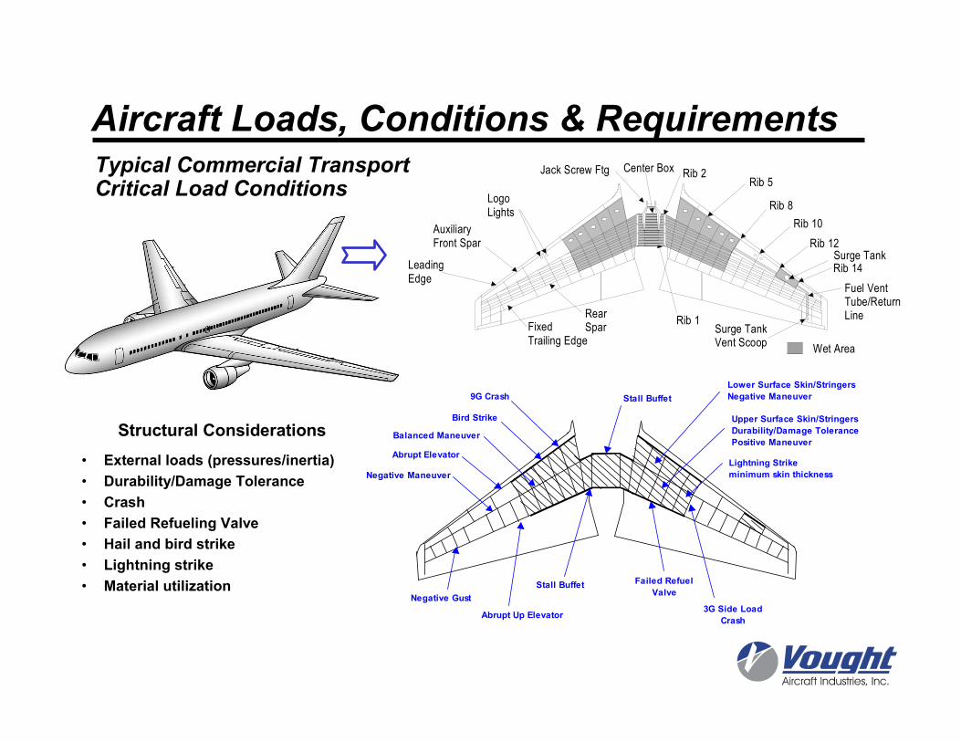
Auxiliary Front Spar
LeadingEdge
RearSpar
LogoLights
FixedTrailing Edge
Surge TankVent Scoop
Rib 5
Rib 8
Rib 10
Rib 12
Rib 14
Wet Area
Jack Screw Ftg Rib 2
Rib 1
Center Box
Fuel VentTube/ReturnLine
Surge Tank
• External loads (pressures/inertia)
• Durability/Damage Tolerance
• Crash
• Failed Refueling Valve
• Hail and bird strike
• Lightning strike
• Material utilization
Structural ConsiderationsBird Strike
Stall Buffet Failed Refuel
Valve
Abrupt Up Elevator
Lightning Strike
minimum skin thickness
Upper Surface Skin/Stringers
Durability/Damage Tolerance
Positive Maneuver
Lower Surface Skin/Stringers
Negative Maneuver
Abrupt Elevator
Negative Maneuver
Balanced Maneuver
Negative Gust
Stall Buffet9G Crash
3G Side Load
Crash
Typical Commercial Transport Critical Load Conditions
Aircraft Loads, Conditions & Requirements
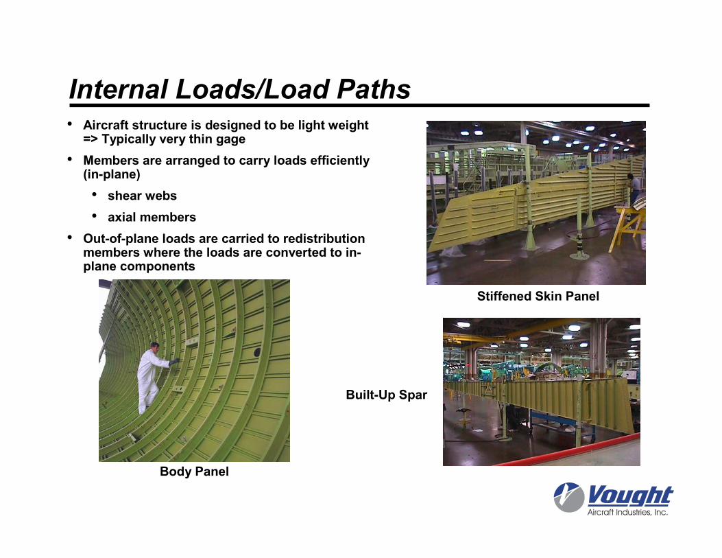
Internal Loads/Load Paths• Aircraft structure is designed to be light weight
=> Typically very thin gage
• Members are arranged to carry loads efficiently (in-plane)
• shear webs
• axial members
• Out-of-plane loads are carried to redistribution members where the loads are converted to in-plane components
Stiffened Skin Panel
Built-Up Spar
Body Panel
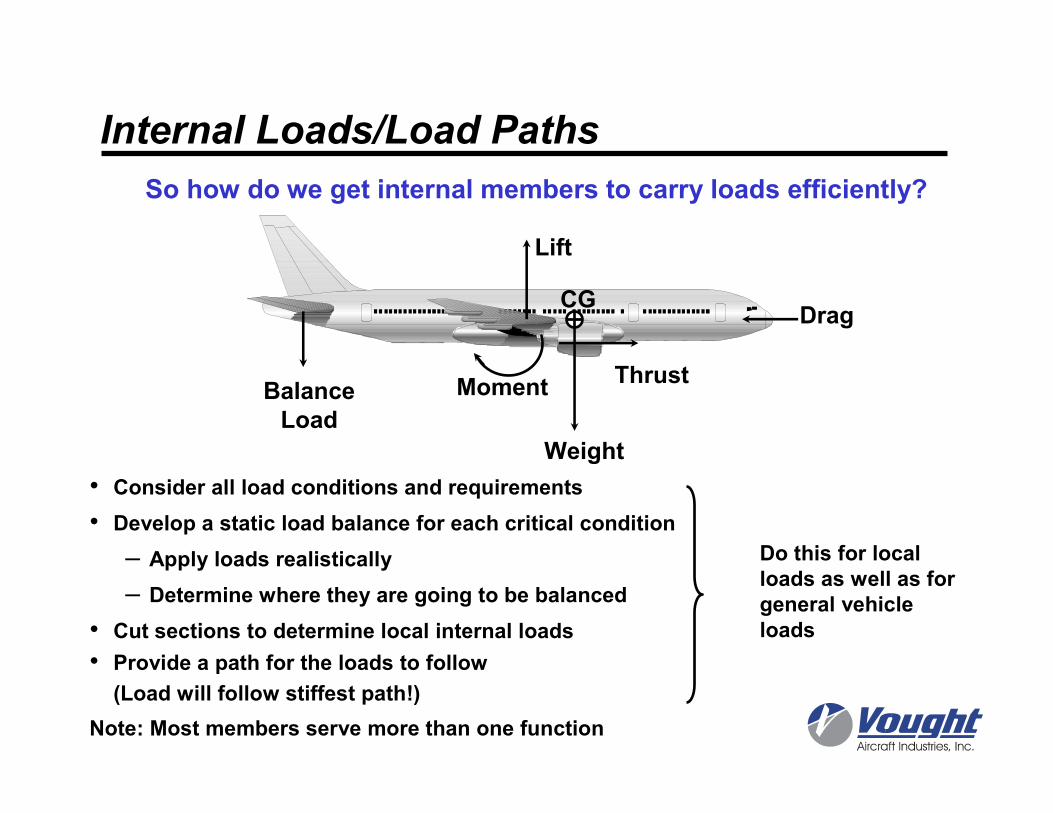
• Consider all load conditions and requirements
• Develop a static load balance for each critical condition
– Apply loads realistically
– Determine where they are going to be balanced
• Cut sections to determine local internal loads
• Provide a path for the loads to follow
(Load will follow stiffest path!)
Note: Most members serve more than one function
So how do we get internal members to carry loads efficiently?
Do this for local loads as well as for general vehicle loads
Internal Loads/Load Paths
Lift
ThrustBalanceLoad
Moment
Weight
CGDrag
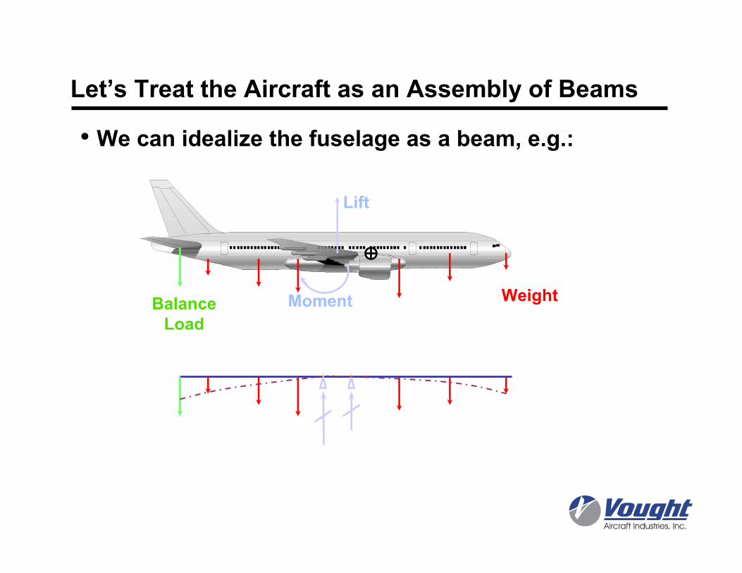
Let’s Treat the Aircraft as an Assembly of Beams
• We can idealize the fuselage as a beam, e.g.:
Lift
BalanceLoad
Moment Weight
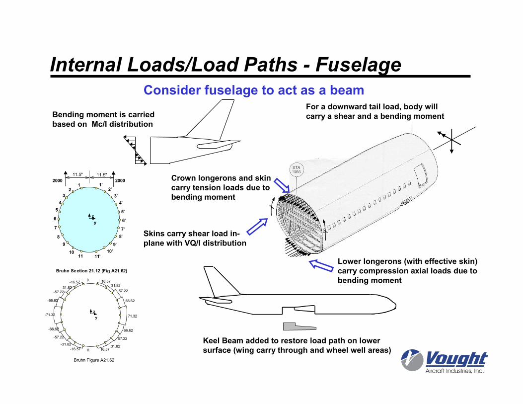
For a downward tail load, body will carry a shear and a bending moment
Skins carry shear load in-plane with VQ/I distribution
Lower longerons (with effective skin)carry compression axial loads due tobending moment
Crown longerons and skin carry tension loads due to bending moment
Bending moment is carried based on Mc/I distribution
Consider fuselage to act as a beam
Keel Beam added to restore load path on lower surface (wing carry through and wheel well areas)
z
y
0.31.82
16.57
71.32
66.62
57.22
-31.82
-16.57
-57.22
-66.62
-71.32
-66.62
-57.22-31.82
-16.570. 16.57
31.82
57.22
66.62
Bruhn Figure A21.62
12
3
4
5
6
7
8
9
1011 11'
10'
9'
8'
7'
6'
5'
4'
3'
2'1'
z
y
2000 2000
11.5" 11.5"
Bruhn Section 21.12 (Fig A21.62)
Internal Loads/Load Paths - Fuselage
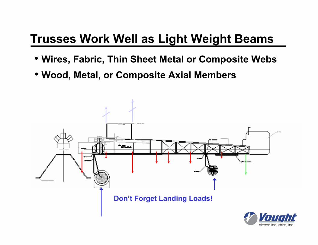
Trusses Work Well as Light Weight Beams
• Wires, Fabric, Thin Sheet Metal or Composite Webs
• Wood, Metal, or Composite Axial Members
Don’t Forget Landing Loads!
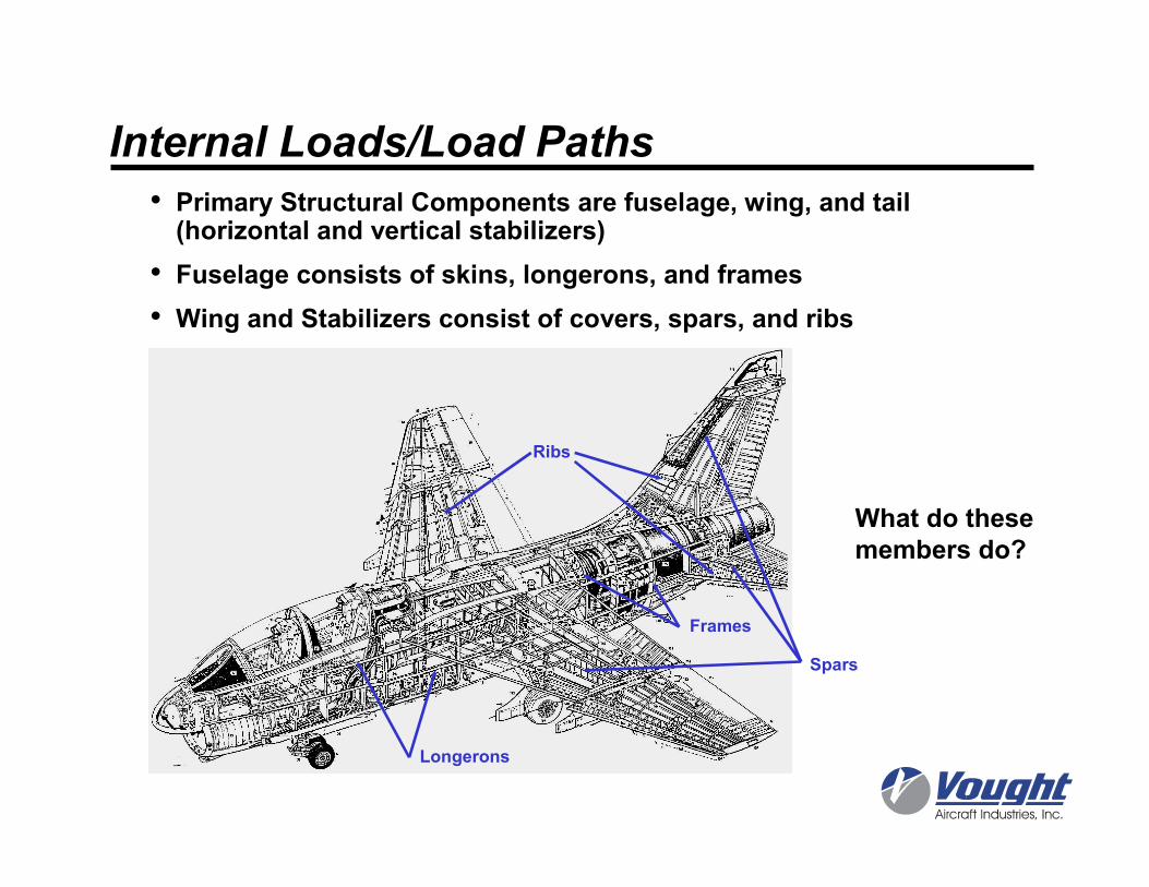
• Primary Structural Components are fuselage, wing, and tail (horizontal and vertical stabilizers)
• Fuselage consists of skins, longerons, and frames
• Wing and Stabilizers consist of covers, spars, and ribs
Spars
Ribs
Frames
Longerons
What do these members do?
Internal Loads/Load Paths
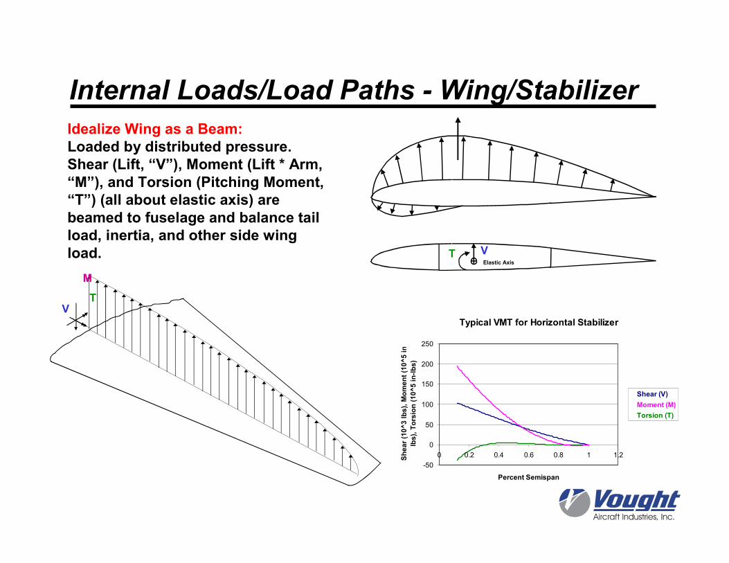
Elastic Axis
Idealize Wing as a Beam:Loaded by distributed pressure.Shear (Lift, “V”), Moment (Lift * Arm, “M”), and Torsion (Pitching Moment, “T”) (all about elastic axis) are beamed to fuselage and balance tail load, inertia, and other side wing load.
Typical VMT for Horizontal Stabilizer
-50
0
50
100
150
200
250
0 0.2 0.4 0.6 0.8 1 1.2
Percent Semispan
Shear (10^3 lbs), Moment (10^5 in-
lbs), Torsion (10^5 in-lbs)
Shear (V)
Moment (M)
Torsion (T)
Internal Loads/Load Paths - Wing/Stabilizer
VT
M
VT
External Loads and Reactions
25"
360"
W
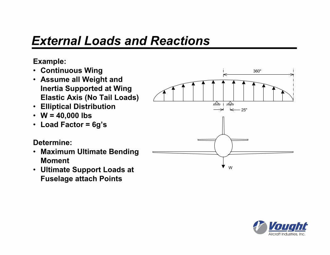
Example:• Continuous Wing• Assume all Weight and Inertia Supported at Wing Elastic Axis (No Tail Loads)
• Elliptical Distribution• W = 40,000 lbs• Load Factor = 6g’s
Determine:• Maximum Ultimate Bending Moment
• Ultimate Support Loads at Fuselage attach Points
External Loads and Reactions
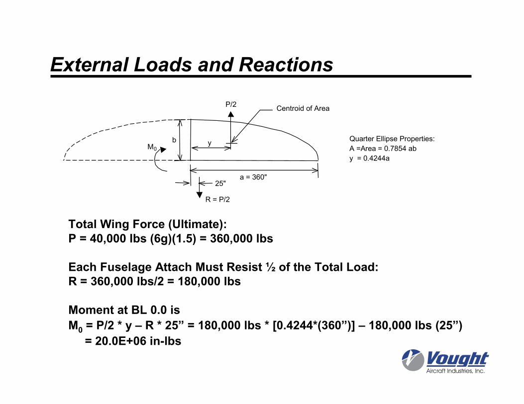
Total Wing Force (Ultimate):P = 40,000 lbs (6g)(1.5) = 360,000 lbs
Each Fuselage Attach Must Resist ½ of the Total Load:R = 360,000 lbs/2 = 180,000 lbs
Moment at BL 0.0 is
M0 = P/2 * y – R * 25” = 180,000 lbs * [0.4244*(360”)] – 180,000 lbs (25”)
= 20.0E+06 in-lbs
Quarter Ellipse Properties:
A =Area = 0.7854 ab
y = 0.4244a
b
a = 360"
y
Centroid of AreaP/2
R = P/2
M0
25"
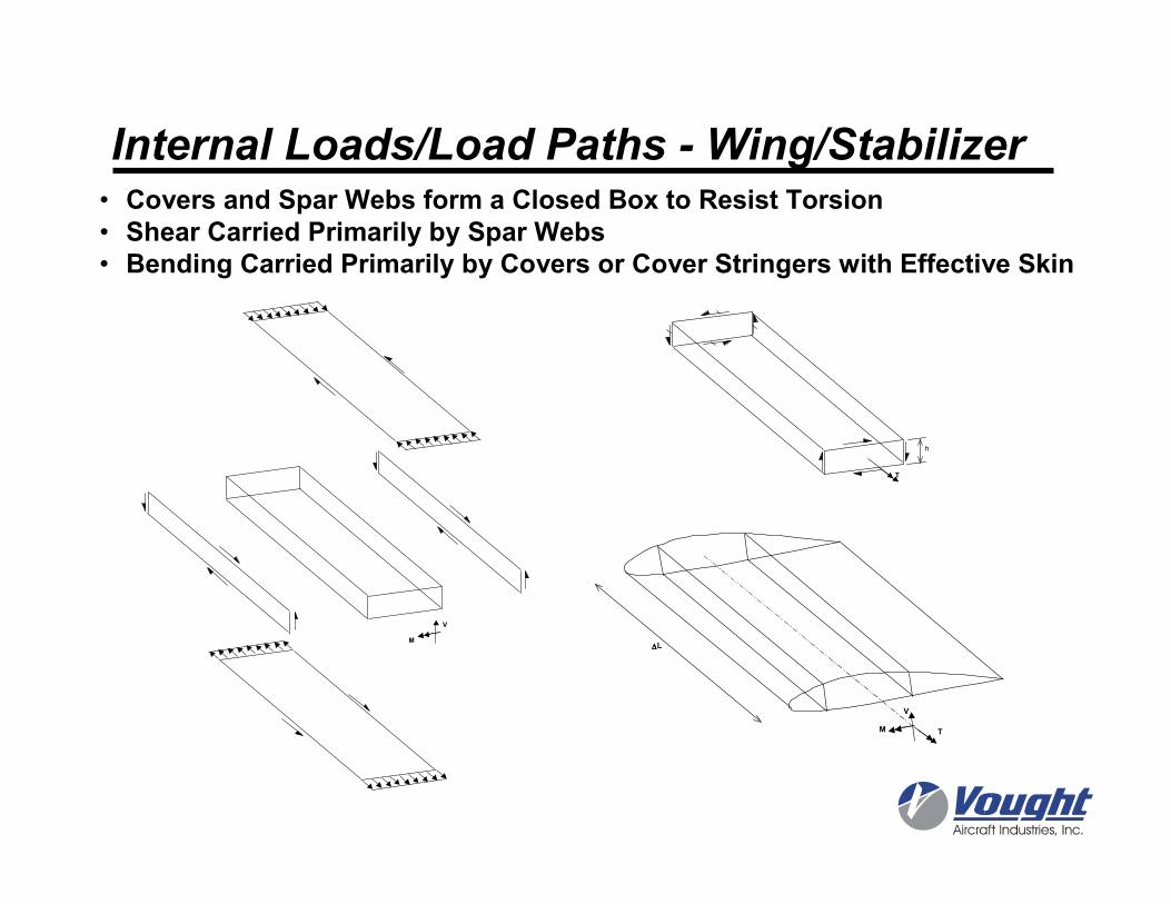
Internal Loads/Load Paths - Wing/Stabilizer• Covers and Spar Webs form a Closed Box to Resist Torsion• Shear Carried Primarily by Spar Webs• Bending Carried Primarily by Covers or Cover Stringers with Effective Skin
T
h
M T
V
∆∆∆∆LM
V
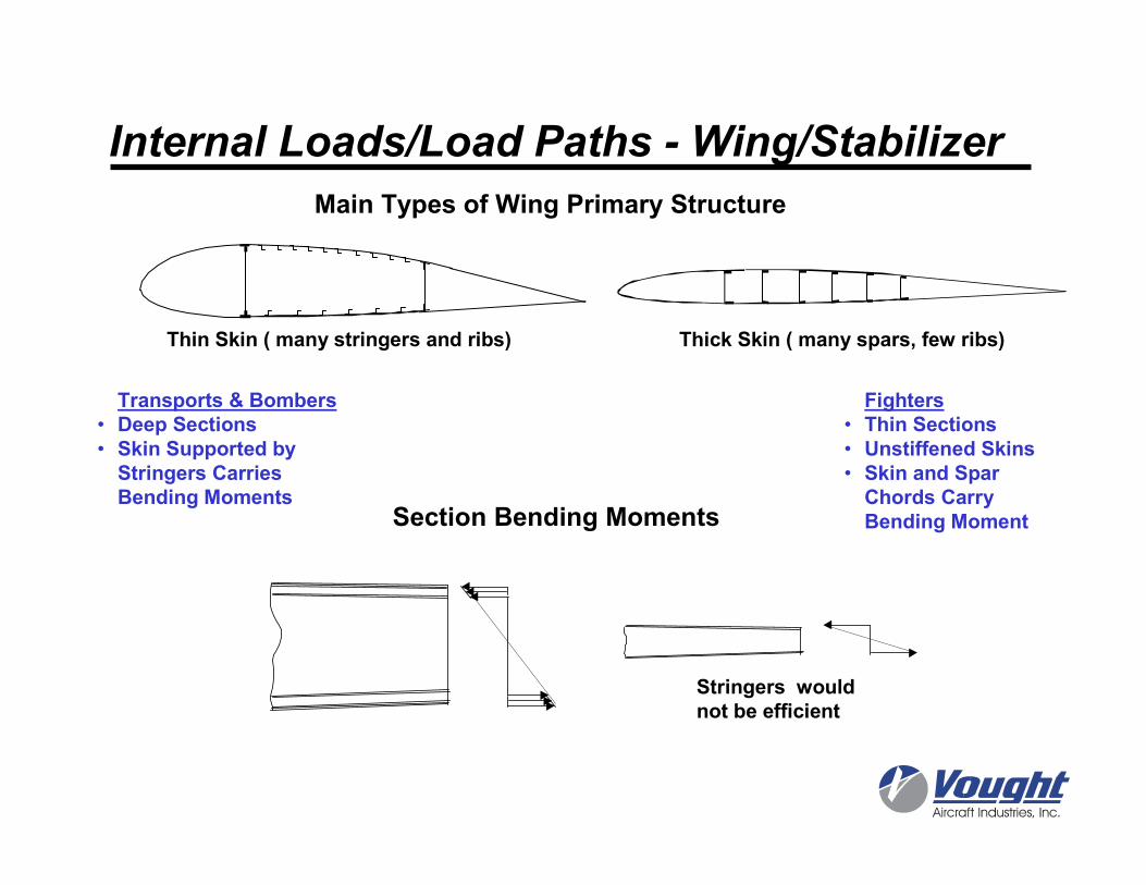
Transports & Bombers• Deep Sections• Skin Supported by Stringers Carries Bending Moments
Fighters• Thin Sections• Unstiffened Skins• Skin and Spar Chords Carry Bending MomentSection Bending Moments
Main Types of Wing Primary Structure
Thin Skin ( many stringers and ribs) Thick Skin ( many spars, few ribs)
Stringers would not be efficient
Internal Loads/Load Paths - Wing/Stabilizer
Internal Loads/Load Paths - Wing/Stabilizer
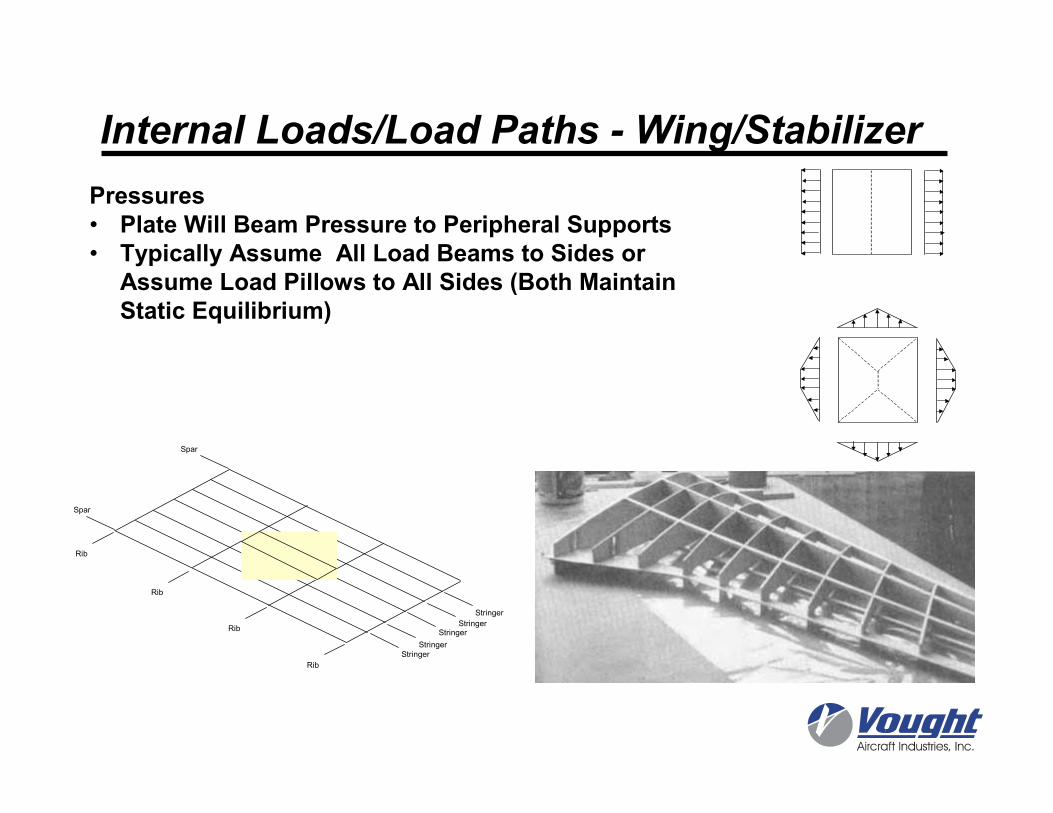
Pressures• Plate Will Beam Pressure to Peripheral Supports• Typically Assume All Load Beams to Sides or
Assume Load Pillows to All Sides (Both Maintain Static Equilibrium)
Spar
Spar
Rib
Rib
Stringer
Stringer
StringerStringer
Stringer
Rib
Rib
bs
S
StringerEffective Area
Rib
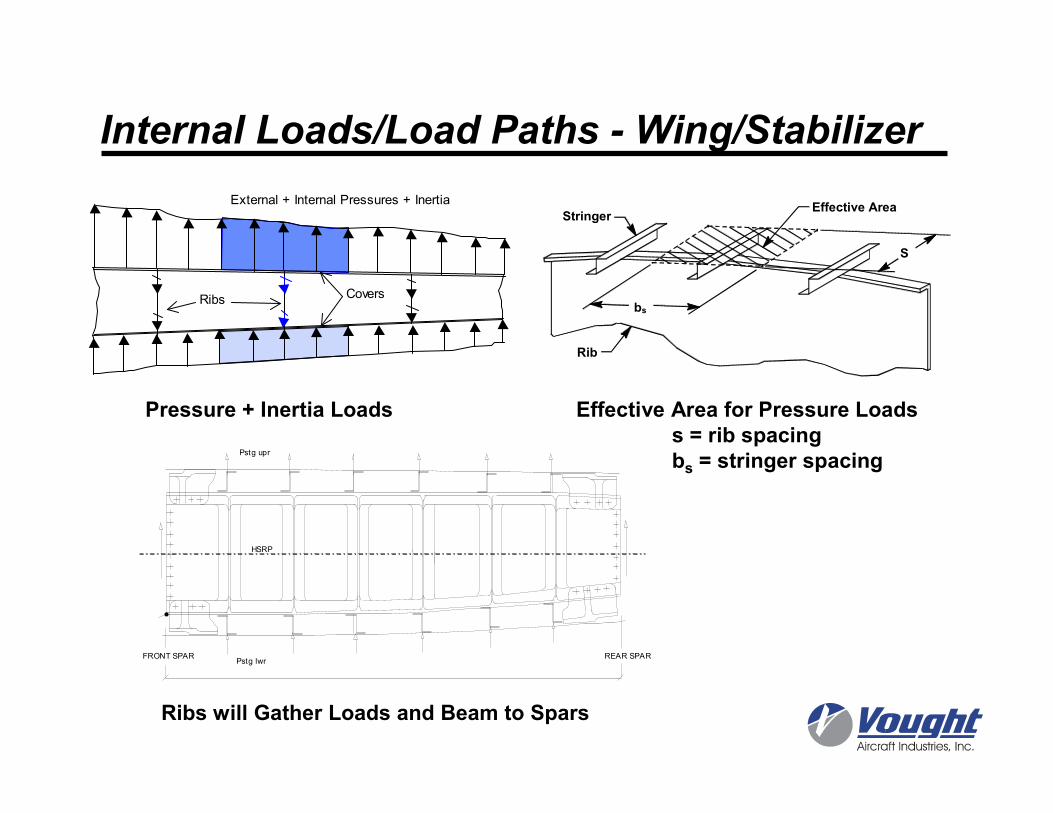
Effective Area for Pressure Loadss = rib spacingbs = stringer spacing
Pressure + Inertia Loads
Ribs Covers
External + Internal Pressures + Inertia
Internal Loads/Load Paths - Wing/Stabilizer
Ribs will Gather Loads and Beam to Spars
FRONT SPAR REAR SPAR
HSRP
Pstg upr
Pstg lwr
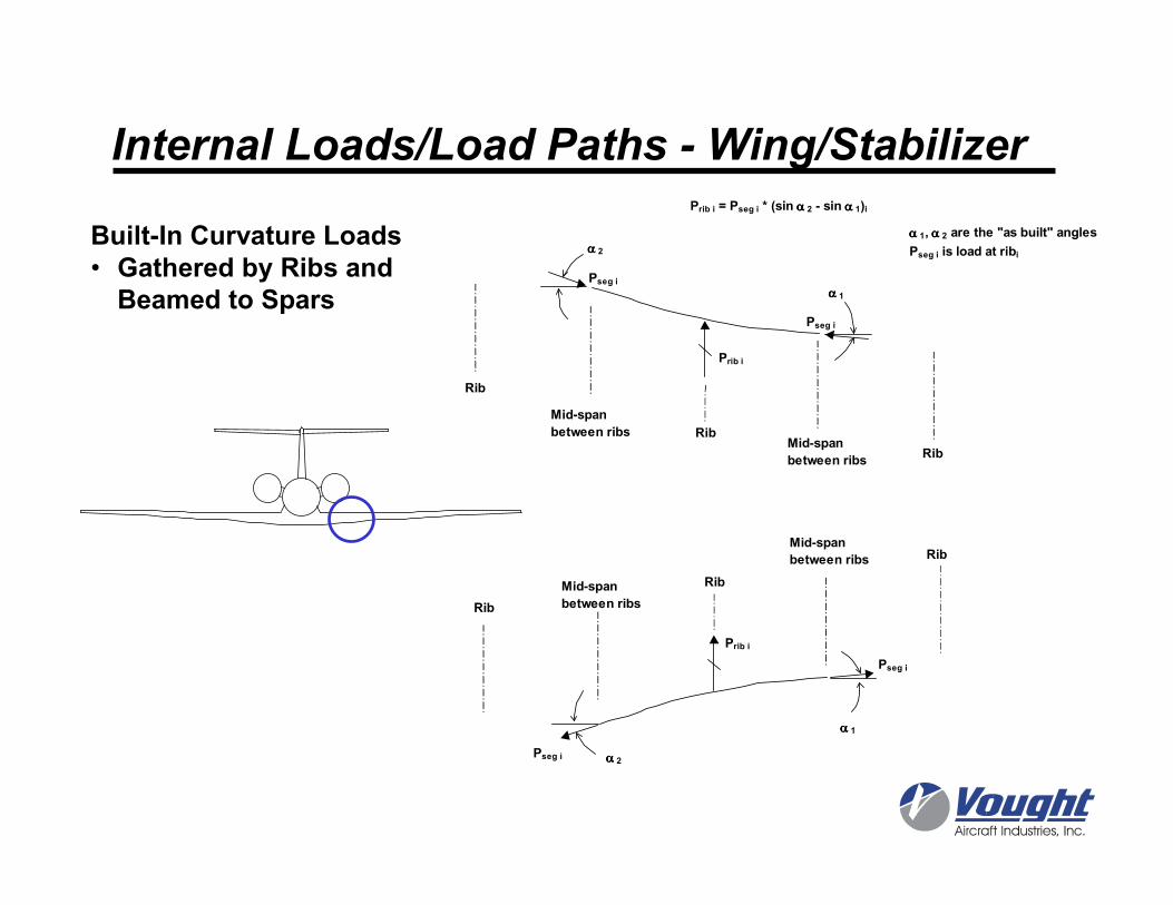
Built-In Curvature Loads• Gathered by Ribs and Beamed to Spars
Internal Loads/Load Paths - Wing/Stabilizer
αααα 2
αααα 1
Pseg i
Pseg i
Prib i
Mid-span
between ribsMid-span
between ribs
Rib
Rib
Rib
Prib i = Pseg i * (sin αααα 2 - sin αααα 1)i
αααα 1, αααα 2 are the "as built" angles
Pseg i is load at ribi
αααα 2
αααα 1
Pseg i
Pseg i
Prib i
Mid-span
between ribs
Mid-span
between ribs
Rib
Rib
Rib
PP
P P
L1 L2Q
Q
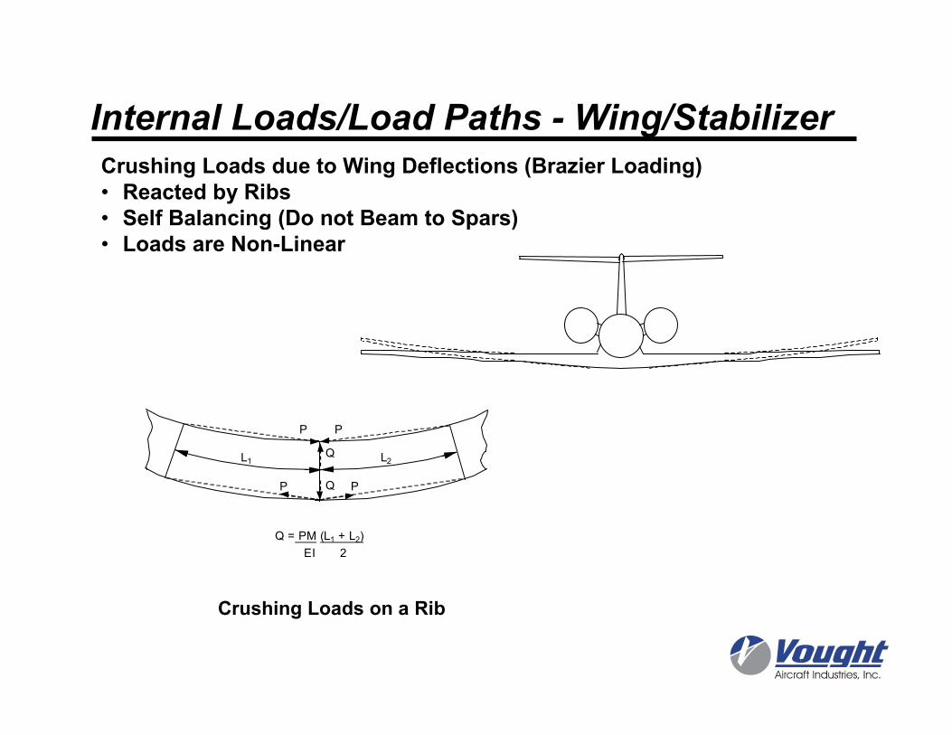
Q = PM (L1 + L2)
EI 2
Crushing Loads on a Rib
Crushing Loads due to Wing Deflections (Brazier Loading)• Reacted by Ribs• Self Balancing (Do not Beam to Spars)• Loads are Non-Linear
Internal Loads/Load Paths - Wing/Stabilizer
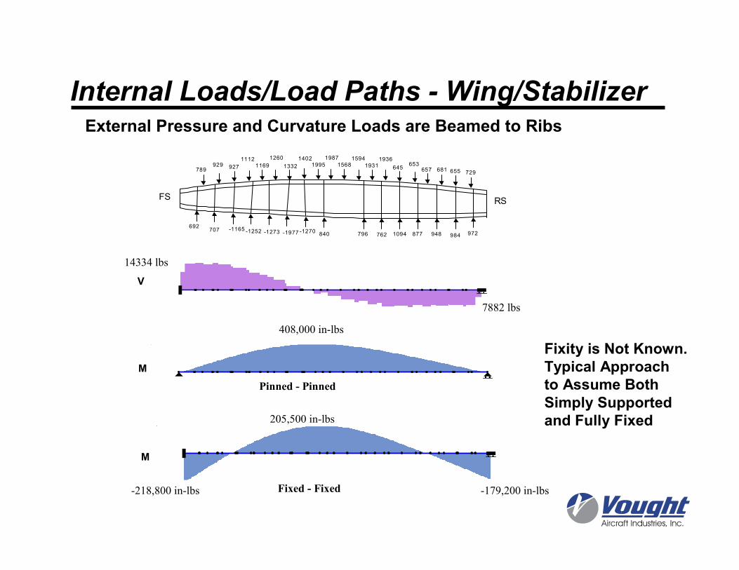
681
Test Flex + Taper Loads (RBS161.5)
729655
6536576451931
193615941568
1987
19951402
1332
1260
11691112
927929789
692707 -1165 -1252 -1273 -1977 -1270
840 796 762 1094 877 948 984 972
FS RS
Internal Loads/Load Paths - Wing/Stabilizer
M
205,500 in-lbs
-218,800 in-lbs -179,200 in-lbsFixed - Fixed
M
408,000 in-lbs
Pinned - Pinned
V
14334 lbs
7882 lbs
External Pressure and Curvature Loads are Beamed to Ribs
Fixity is Not Known. Typical Approach to Assume Both Simply Supported and Fully Fixed
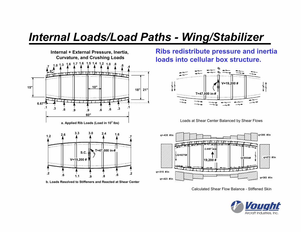
.1 .3 .6 .9 .9 .6 .6 .3 .1
.7 1.0 1.3 1.6 1.7 1.6 1.2 1.0 .8 .6 .41.41.5
10"15"
5"
6.67"
21"18"
60"
.2.6 1.1 .9 .8 .6 .2
1.2 2.6 3.3 2.4 1.6.7
3.0
S.C.
V=19,200 #
a. Applied Rib Loads (Load in 103 lbs)
b. Loads Resolved to Stiffeners and Reacted at Shear Center
T=47,000 in-#
qtqv
V=19,200 #
T=47,000 in-#
Loads at Shear Center Balanced by Shear Flows
2.448"
19,200 #
q=-515 #/in
q=-435 #/in
q=-423 #/in
q=395 #/in
q=383 #/in
q=475 #/inQ=9275#
Q=8554#
Calculated Shear Flow Balance - Stiffened Skin
Internal + External Pressure, Inertia, Curvature, and Crushing Loads
Internal Loads/Load Paths - Wing/StabilizerRibs redistribute pressure and inertia loads into cellular box structure.
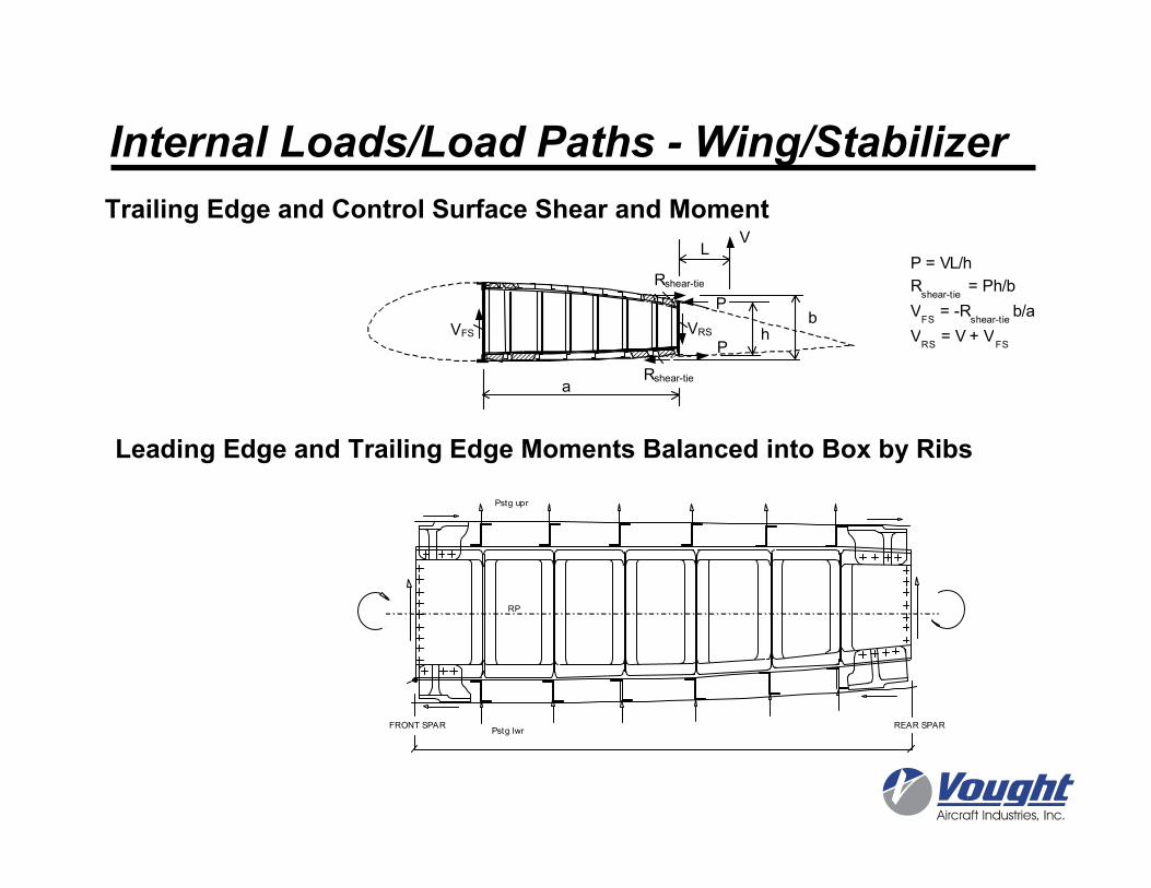
FRONT SPAR REAR SPAR
RP
Pstg upr
Pstg lwr
h P
R shear-tie
b P
R shear-tie a
V FS V RS
V L
P = VL/h
Rshear-tie
= Ph/b
VFS
= -Rshear-tie
b/a
VRS
= V + VFS
Internal Loads/Load Paths - Wing/Stabilizer
Trailing Edge and Control Surface Shear and Moment
Leading Edge and Trailing Edge Moments Balanced into Box by Ribs
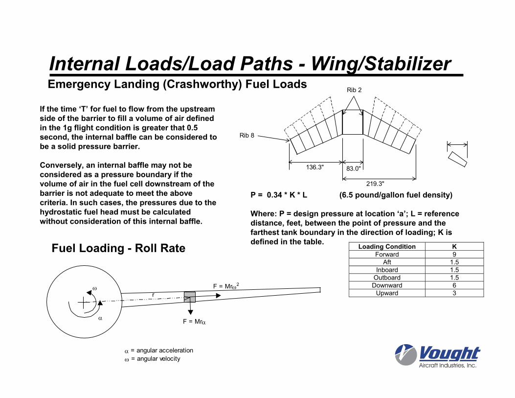
Rib 2
Rib 8
136.3" 83.0"
219.3"
If the time ‘T’ for fuel to flow from the upstream side of the barrier to fill a volume of air defined in the 1g flight condition is greater that 0.5 second, the internal baffle can be considered to be a solid pressure barrier.
Conversely, an internal baffle may not be considered as a pressure boundary if the volume of air in the fuel cell downstream of the barrier is not adequate to meet the above criteria. In such cases, the pressures due to the hydrostatic fuel head must be calculated without consideration of this internal baffle.
P = 0.34 * K * L (6.5 pound/gallon fuel density)
Where: P = design pressure at location ‘a’; L = reference distance, feet, between the point of pressure and the farthest tank boundary in the direction of loading; K is defined in the table.
Emergency Landing (Crashworthy) Fuel Loads
Fuel Loading - Roll Rate Loading Condition KForward 9
Aft 1.5
Inboard 1.5
Outboard 1.5
Downward 6
Upward 3
Internal Loads/Load Paths - Wing/Stabilizer
F = Mrω2
F = Mrα
ω
α
α = angular acceleration
ω = angular velocity
r
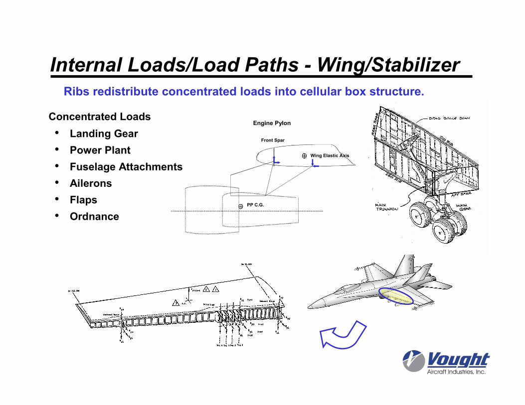
Concentrated Loads
• Landing Gear
• Power Plant
• Fuselage Attachments
• Ailerons
• Flaps
• Ordnance
Engine Pylon
Wing Elastic Axis
PP C.G.
Front Spar
Ribs redistribute concentrated loads into cellular box structure.
Internal Loads/Load Paths - Wing/Stabilizer
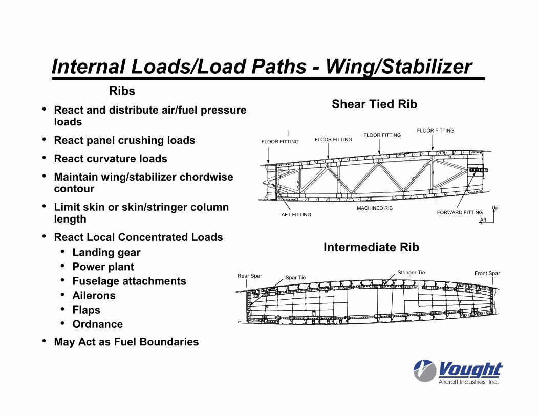
Ribs
• React and distribute air/fuel pressure loads
• React panel crushing loads
• React curvature loads
• Maintain wing/stabilizer chordwisecontour
• Limit skin or skin/stringer column length
• React Local Concentrated Loads
• Landing gear
• Power plant
• Fuselage attachments
• Ailerons
• Flaps
• Ordnance
• May Act as Fuel Boundaries
Shear Tied Rib
Intermediate Rib
Internal Loads/Load Paths - Wing/Stabilizer
Rear SparFront SparStringer Tie
Spar Tie
AFT FITTING FORWARD FITTING MACHINED RIB
FLOOR FITTINGFLOOR FITTING
FLOOR FITTING FLOOR FITTING
Up
Aft
Chord
Upright or Rib Post
Web
Chord
Strut
Rib Post
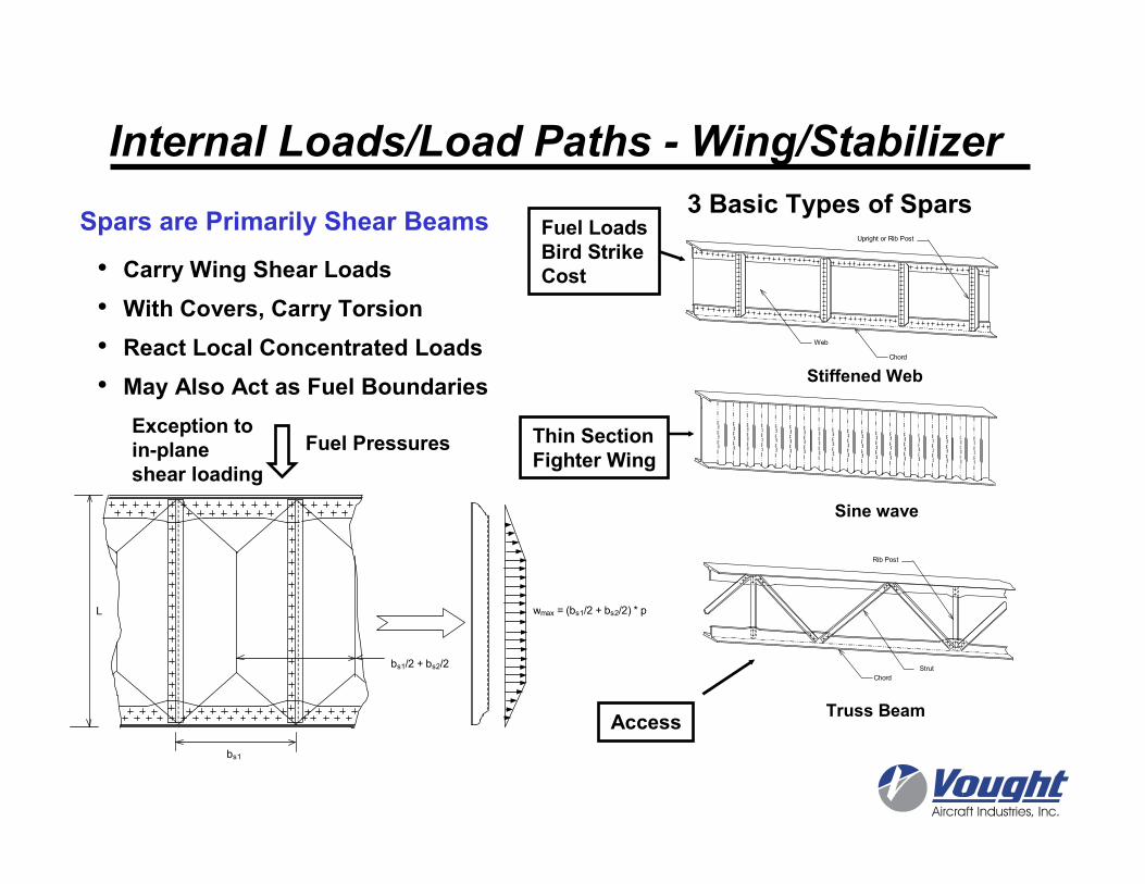
• Carry Wing Shear Loads
• With Covers, Carry Torsion
• React Local Concentrated Loads
• May Also Act as Fuel Boundaries
Spars are Primarily Shear Beams3 Basic Types of Spars
Stiffened Web
Sine wave
Truss Beam
Exception toin-plane shear loading
Fuel Pressures
Fuel LoadsBird StrikeCost
Access
Thin SectionFighter Wing
bs1
L wmax = (bs1/2 + bs2/2) * p
bs1/2 + bs2/2
Internal Loads/Load Paths - Wing/Stabilizer
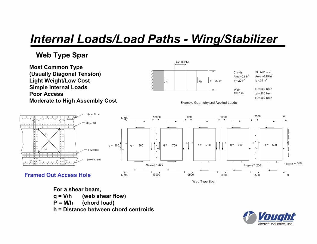
5.0" (5 PL)
20.0"
Chords:
Area =0.6 in2
Iy =.20 in4
Struts/Posts:
Area =0.45 in2
Iy =.06 in4
Web:
t =0.1 in
q1 q2 q3
q1 = 200 lbs/in
q2 = 200 lbs/in
q3 = 500 lbs/in
0
500
500700700700900
0
200200
9500 6000 250017500 13000
900 q = q =q =q =q = q =
25009500 60001300017500
q(applied) =q(applied) =q(applied) =
Web Type Spar
Example Geometry and Applied Loads
Most Common Type(Usually Diagonal Tension)Light Weight/Low CostSimple Internal LoadsPoor AccessModerate to High Assembly Cost
For a shear beam, q = V/h (web shear flow)P = M/h (chord load)h = Distance between chord centroids
Upper Chord
Lower Chord
Upper Sill
Lower Sill
L1
L2
Framed Out Access Hole
Web Type Spar
Internal Loads/Load Paths - Wing/Stabilizer
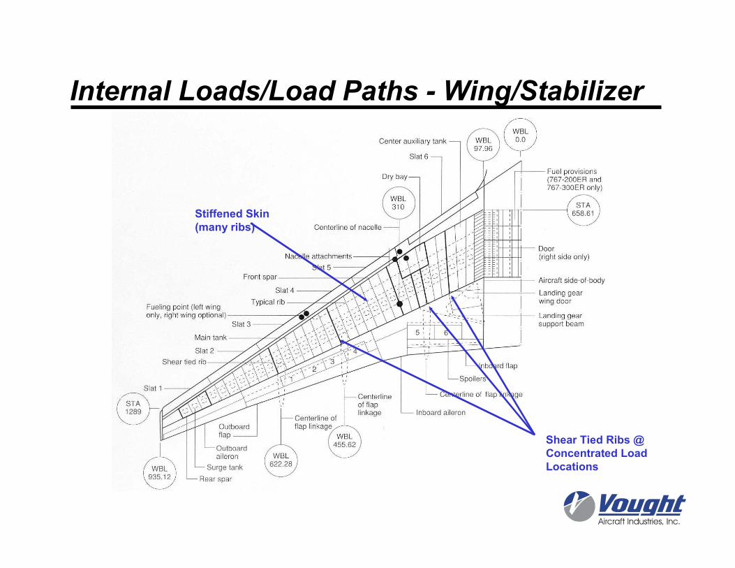
Stiffened Skin(many ribs)
Shear Tied Ribs @ Concentrated Load Locations
Internal Loads/Load Paths - Wing/Stabilizer
Internal Loads/Load Paths -Fuselage
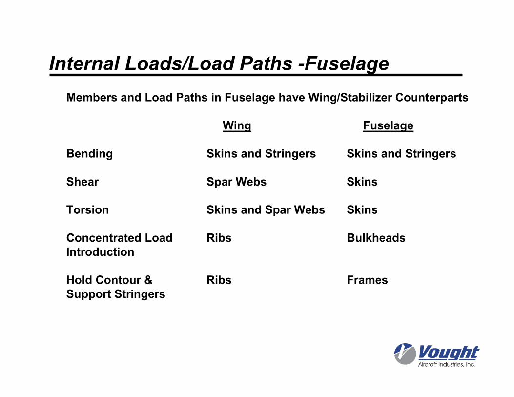
Members and Load Paths in Fuselage have Wing/Stabilizer Counterparts
Wing Fuselage
Bending Skins and Stringers Skins and Stringers
Shear Spar Webs Skins
Torsion Skins and Spar Webs Skins
Concentrated Load Ribs BulkheadsIntroduction
Hold Contour & Ribs FramesSupport Stringers
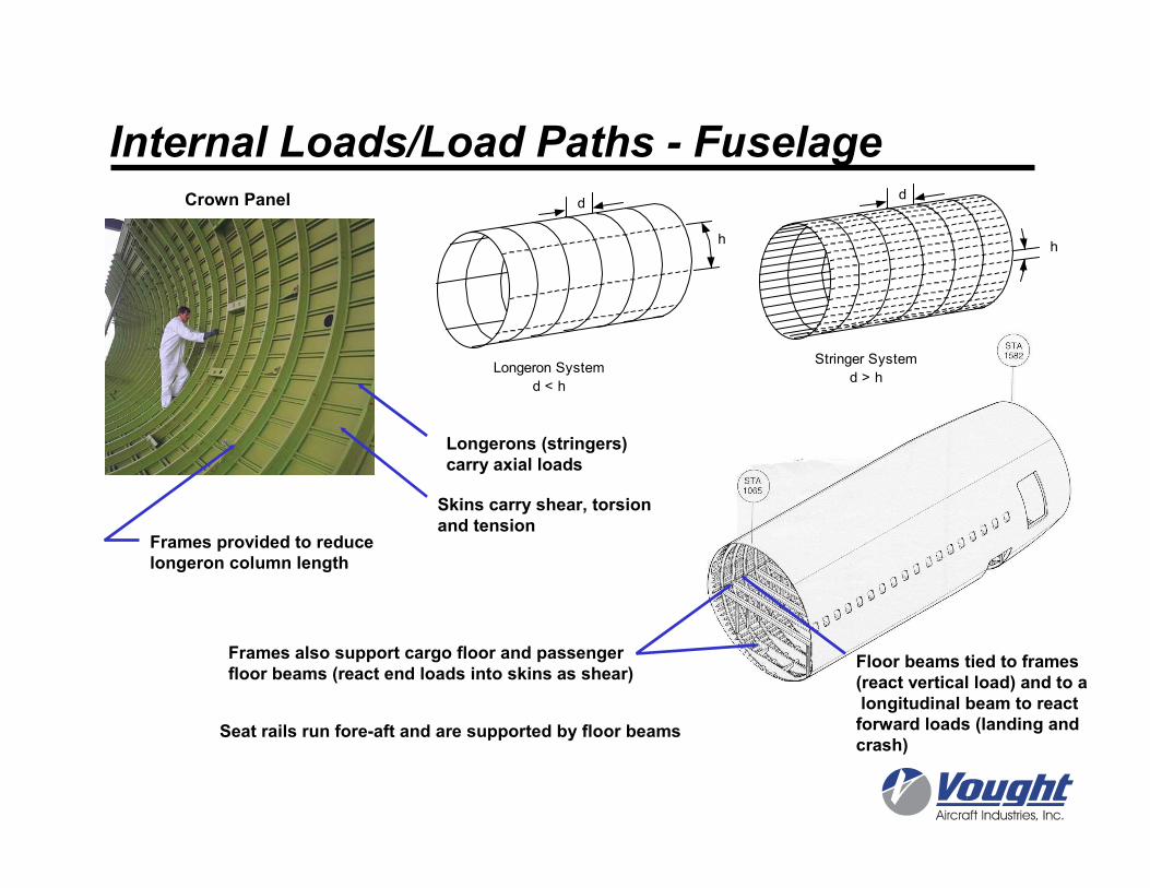
Longerons (stringers) carry axial loads
Frames provided to reducelongeron column length
Skins carry shear, torsionand tension
Frames also support cargo floor and passenger floor beams (react end loads into skins as shear)
Seat rails run fore-aft and are supported by floor beams
Floor beams tied to frames (react vertical load) and to alongitudinal beam to react forward loads (landing and crash)
d
h
Stringer System
d > h
d
h
Longeron System
d < h
Internal Loads/Load Paths - FuselageCrown Panel
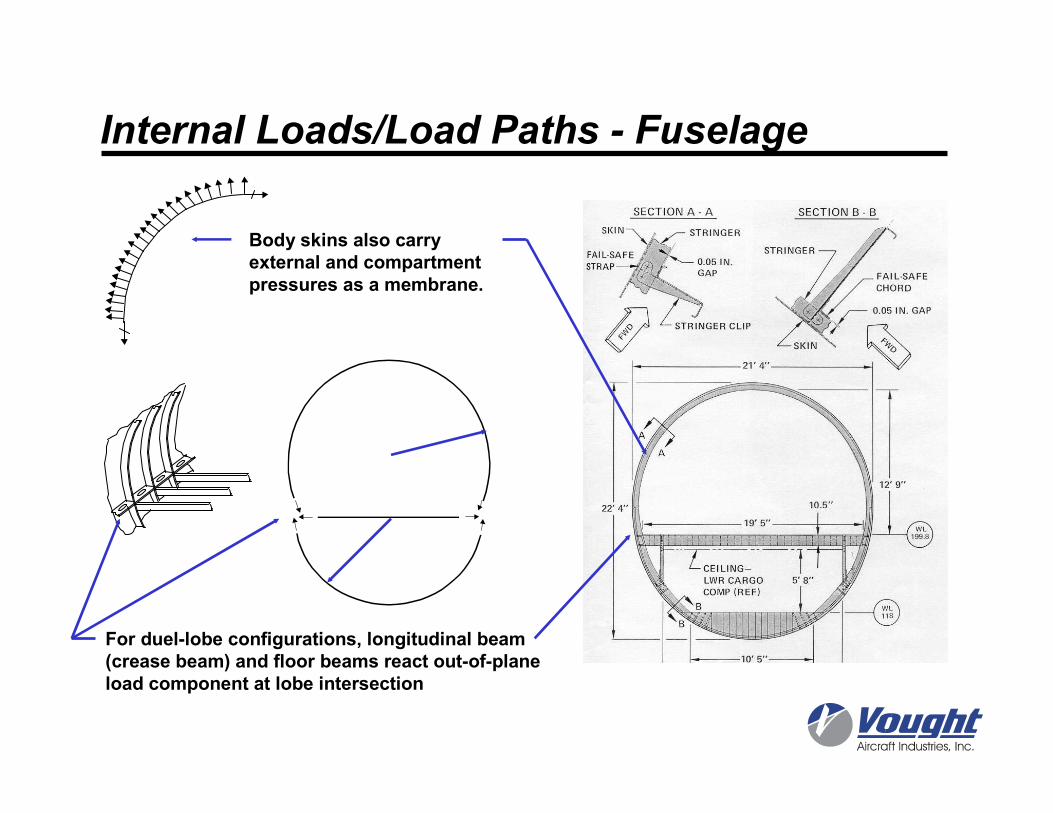
Body skins also carry external and compartmentpressures as a membrane.
For duel-lobe configurations, longitudinal beam(crease beam) and floor beams react out-of-planeload component at lobe intersection
Internal Loads/Load Paths - Fuselage
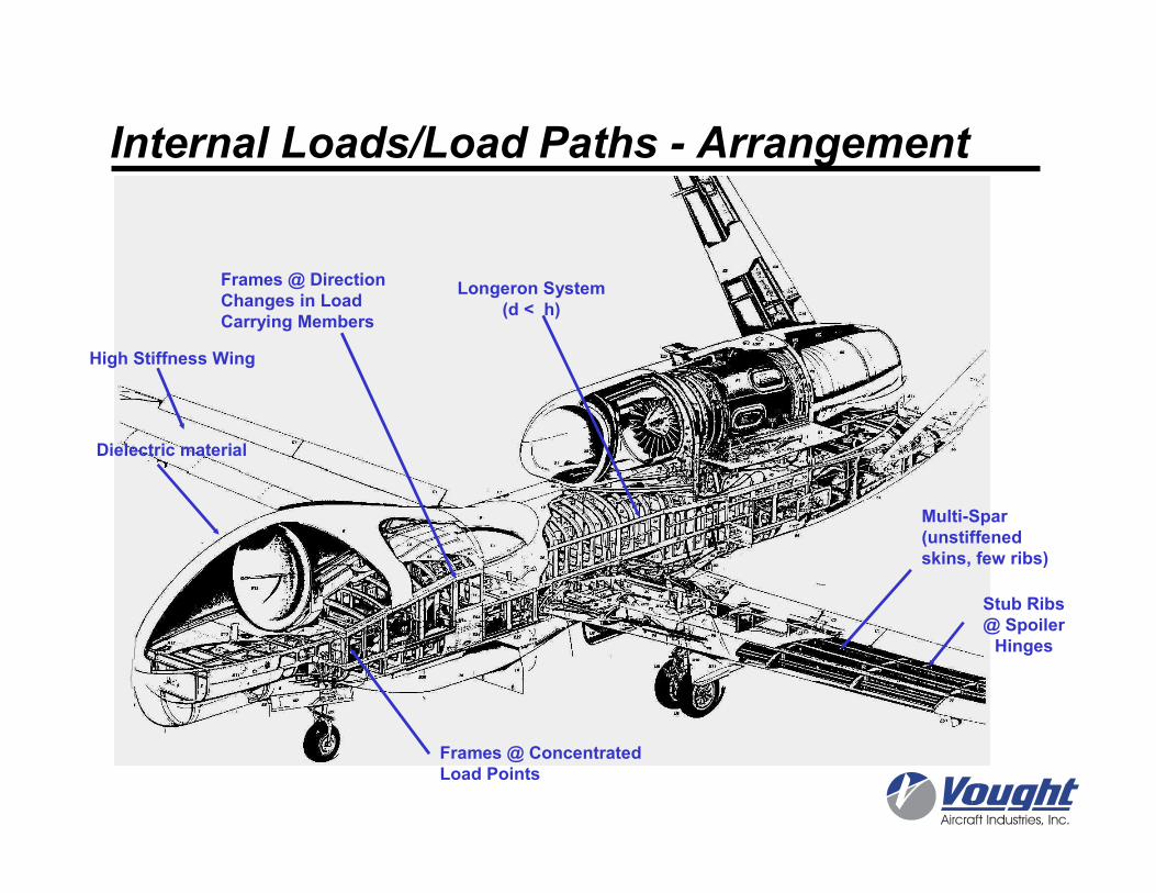
Internal Loads/Load Paths - Arrangement
Frames @ Concentrated Load Points
Frames @ Direction Changes in Load Carrying Members
Longeron System(d < h)
Multi-Spar(unstiffenedskins, few ribs)
Dielectric material
High Stiffness Wing
Stub Ribs@ SpoilerHinges
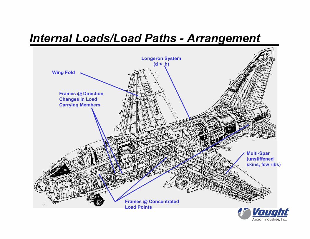
Longeron System(d < h)
Multi-Spar(unstiffenedskins, few ribs)
Frames @ Concentrated Load Points
Frames @ Direction Changes in Load Carrying Members
Wing Fold
Internal Loads/Load Paths - Arrangement
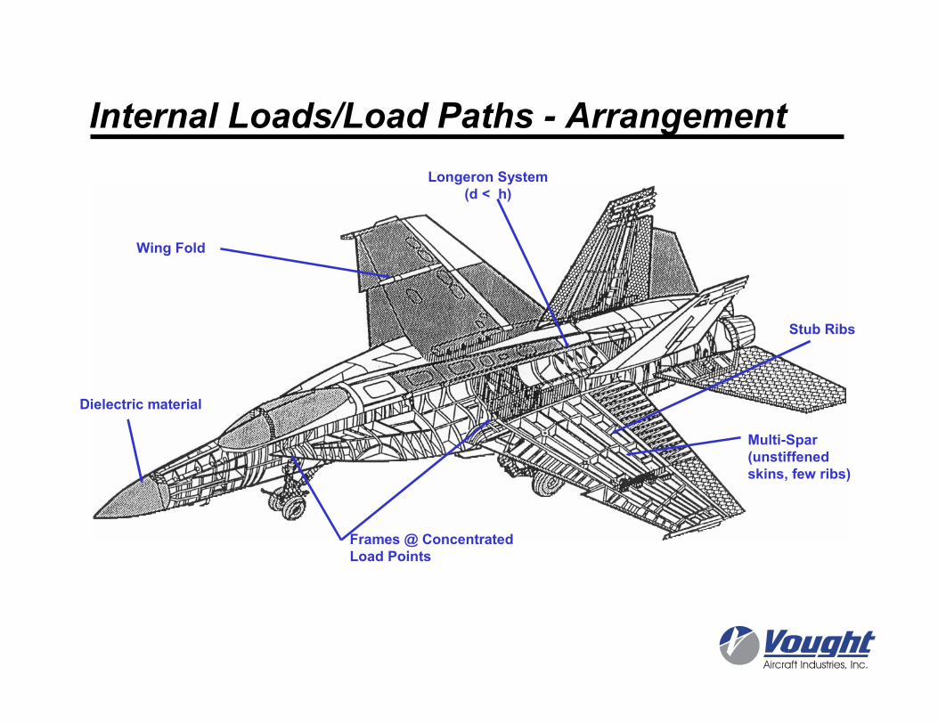
Multi-Spar(unstiffenedskins, few ribs)
Longeron System(d < h)
Dielectric material
Stub Ribs
Frames @ Concentrated Load Points
Wing Fold
Internal Loads/Load Paths - Arrangement
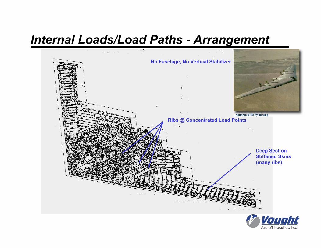
Deep SectionStiffened Skins(many ribs)
No Fuselage, No Vertical Stabilizer
Ribs @ Concentrated Load Points
Internal Loads/Load Paths - Arrangement
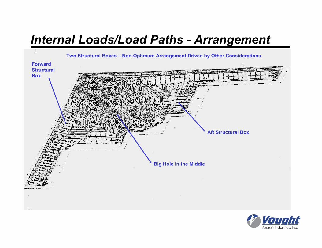
Two Structural Boxes – Non-Optimum Arrangement Driven by Other Considerations
ForwardStructuralBox
Aft Structural Box
Big Hole in the Middle
Internal Loads/Load Paths - Arrangement
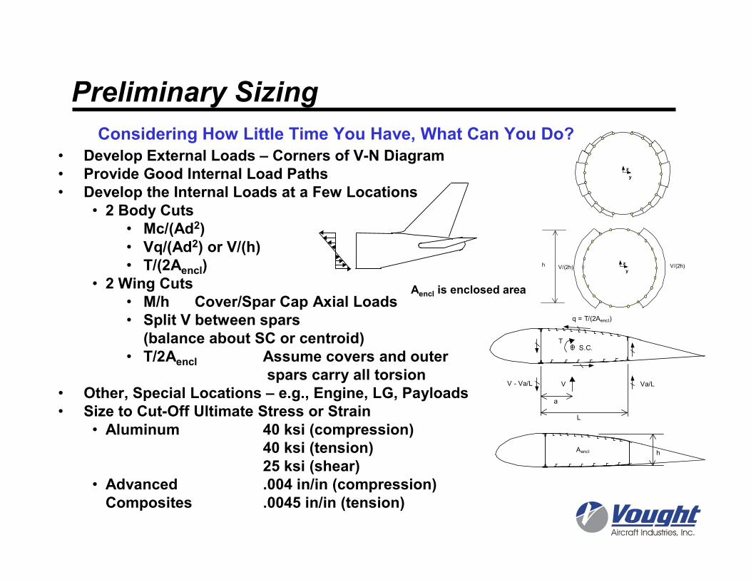
Preliminary Sizing
Considering How Little Time You Have, What Can You Do?
• Develop External Loads – Corners of V-N Diagram• Provide Good Internal Load Paths• Develop the Internal Loads at a Few Locations
• 2 Body Cuts• Mc/(Ad2)• Vq/(Ad2) or V/(h)• T/(2Aencl)
• 2 Wing Cuts• M/h Cover/Spar Cap Axial Loads• Split V between spars (balance about SC or centroid)
• T/2Aencl Assume covers and outerspars carry all torsion
• Other, Special Locations – e.g., Engine, LG, Payloads• Size to Cut-Off Ultimate Stress or Strain
• Aluminum 40 ksi (compression)40 ksi (tension)25 ksi (shear)
• Advanced .004 in/in (compression)Composites .0045 in/in (tension)
Aencl is enclosed area
Aencl h
S.C.T
V
a
L
Va/LV - Va/L
q = T/(2Aencl)
z
y
h V/(2h)V/(2h)
z
y
Some References
• Airframe Structural Design, Niu, Michael C.Y., Conmilit Press LTD., 1988.
• Airplane Design, Roskam, Dr. Jan, Roskam Aviation and Engineering Corporation, Ottawa, Kansas, 1985.• Part I: Preliminary Sizing of Airplanes• Part III: Layout Design of Cockpit, Fuselage, Wing and Empennage: Cutaways and Inboard Profiles
• http://www.aoe.vt.edu/~mason/Mason_f/SD1L32pp.pdf• http://www.theflightcollection.com/index.jsp• FAA Regulations Online, Plug “CFR 14” Into Search Engine – Look
For “Part 23”
• Analysis & Design of Flight Vehicle Structures, Bruhn, E.F., Tri-State Offset Company, Cincinnati, Ohio, 1965.
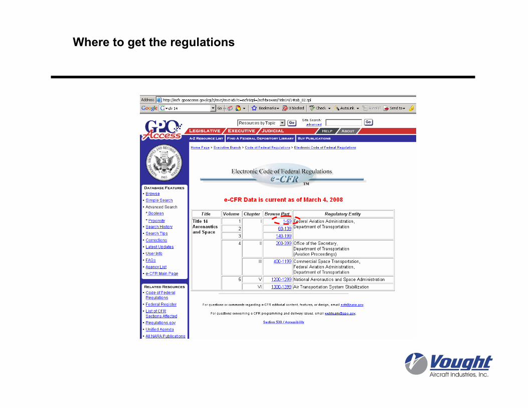
Where to get the regulations
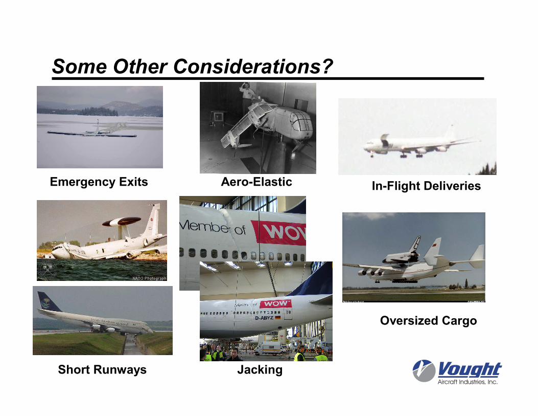
Some Other Considerations?
Short Runways
Aero-Elastic In-Flight Deliveries
Oversized Cargo
Jacking
Emergency Exits


![Theoretical considerations of static and dynamic ...prem.hanyang.ac.kr/down/Theoretical considerations of...Tribology International ] (]]]]) ]]]–]]] Theoretical considerations of](https://img.pdfslide.us/doc/110x75/5aa5e7d57f8b9a7c1a8e0cba/theoretical-considerations-of-static-and-dynamic-prem-considerations-oftribology.jpg)