Embed Size (px)
Citation preview
Aircraft Mishap Investigation
In i u ries: Number
Single Engine Disassembly Report
Fatal I Serious I Minor I None
Aircraft Registration: N1110N Mishap Time (24 hr.): 735 CST
Mishap Date: 03/27/2000 Air Safety Investigator: Robert C. Ohnmeiss
Aircraft Manufacturer: Hughes (1981) Aircraft Model: 269C Mishap Location: Del Rio, TX Aircraft SIN: 61 1064
Federal IIC: Alan Stone - NTSB, Miami On Scene Examination: Yes
Crew 1 1 0 0 I 0
Passengers
Ground
Registered Owner: Go Helicopters Operator: USDAlAPHlSNViIdlife Services 8913 Paul B. Koonce St. Houston, TX 77061
21 13 Osuna Road, NE Albuquerque, NM 871 13
1 1 0 0 0
0 0 0 0
Phone Investigation Supplement: 0 Yes a No
Phone Investigation Performed by:
Field Investigation Supplement: a y e s U N O
Field Investigation Performed by: Gerald R. James - TEXTRON (ASI)
Engine Disassembly Requested by:
Engine Disassembly Conducted by:
Engine Disassembly Date: June 27,2000
Alan Stone - NTSB
Bob Stockslager - FAA & Robert Ohnmeiss - TEXTRON
Disassembly Location: TEXTRON Lycoming
652 Oliver St.
Williamsport, PA 17701
Engine Disassembly Report (Cont.) Page: 2
Engine As Received or First Viewed I I
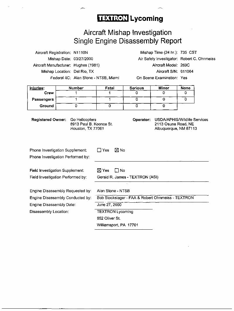
1. Fuel pump housing broken from engine in area of flange mounting.
2. Both the left and right magnetos were missing from the engine.
3. The crankcase was stamped with Ajax rework numbers 16255 & WDC 51655.
4. Oil filler tube & gage were missing from the engine.
5. The oil sump was impact broken from the engine and in pieces, with the crankcase broken at the oil sump-mounting flange.
6. The fuel injector housing was impact broken into pieces.
7. The fuel injector nozzles and injector lines were missing from the accident engine.
8. The engine oil suction screen was missing.
9. # 1 cylinder exhaust & # 2 cylinders intake, shroud tubes were impact damaged.
IO . The center oil cooler and oil breather fittings were impact broken from the accessory housing.
11. The intake and exhaust pipes were broken from all four cylinders.
12. All four-rocker covers were missing from the cylinders.
13. The ignition harness was missing from the as-received accident engine.
14. The starter and alternator were not with the as-received accident engine.
Engine Disassembly Report (Cont.) Page: 3
Enaine:
Engine Data
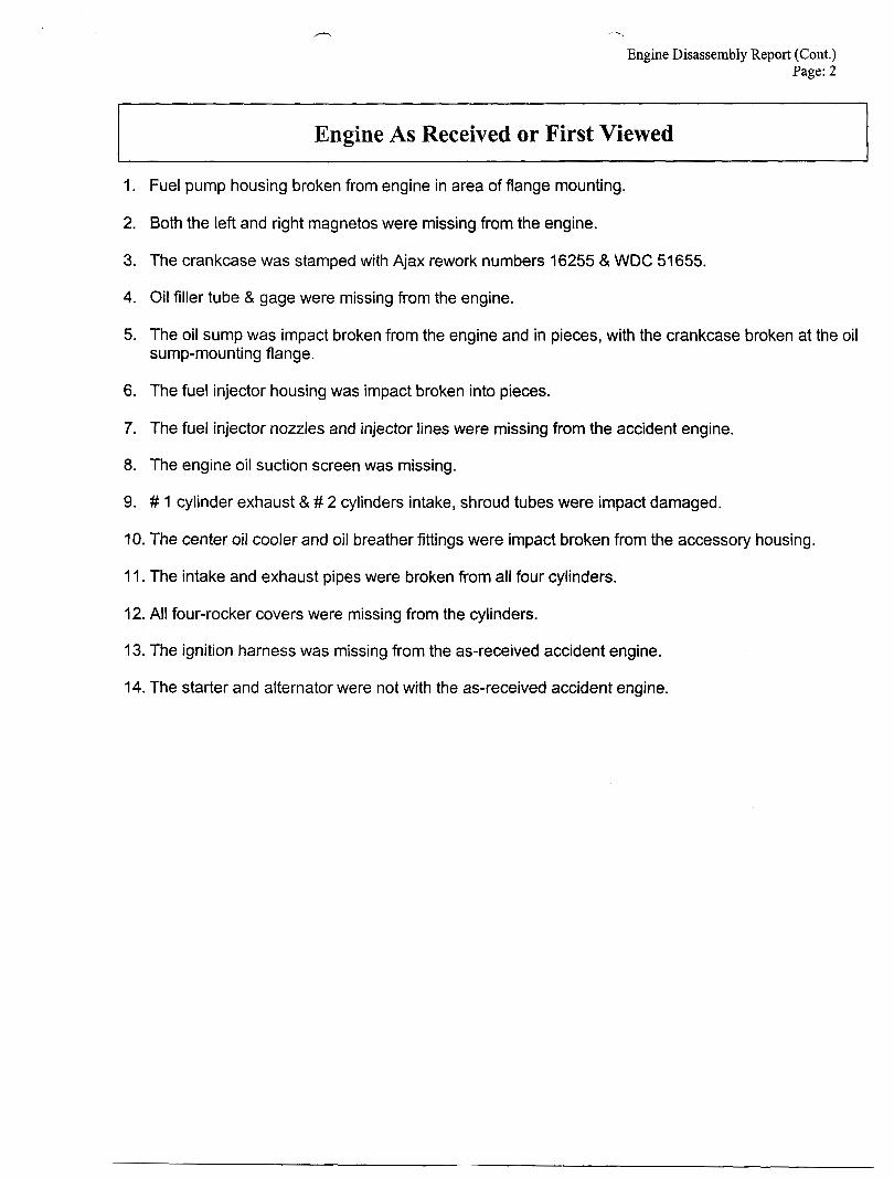
Model Serial Number Total Time H I0-360-D 1 A L-21305-51A 31.5 Hours Since Major O/H
Hours Since
Date of Last Annual Inspection: March 01, 1999
Overhauled by: Powerstroke Aviation
Maintenance Records Attached: Yes 0 No
Tach Time as of Accident: Unknown Hobbs Time as of Accident: Unknown
Engine S/N on Case: L-21305-51 A Match Number: 2784
Last Overhaul by: Powerstroke Avia. Overhaul Location: San Antonio, TX Date: 0211 6/00
Propeller Governor:
Manufacturer: Part No.: N/A
Gasket Screen Clean: Yes 0 No 0 Unknown 0 Additional Comments: No Propeller on this installation.
Governor Oil Line: Properly Secured? Correct Line Nuts?
Correct Fittings?
0 Yes 0 Yes
0 Yes
0 Unknown
0 Unknown
Unknown
Serial No.: N/A
N/A
N/A NIA
Additional Comments:

Engine Disassembly Report (Cont.) Pace: 4 r Engine Data
Magnetos:
Left or 0 Dual Magneto Manufacturer: Unk. Model: Unk. P/N Unk. S/N Unk.
Impulse Coupling? 0 Yes No Functioning? [7 Yes No 0 Unknown
Damage:
Right Magneto
Manufacturer: Unk. Model: Unk. PIN Unk. S/N Unk.
Impulse Coupling? 0 Yes No Functioning? Yes 0 No 0 Unknown
Damage:
Magneto missing from as-received accident engine.
Magneto missing from as-received accident engine.
Magneto Comments:
Fuel System IXI Injection 0 Carburetor
Manufacturer: Unk. Model: Unk. Setting: Unk.
Serial. No.: Unk. Floats: 0 Metal 0 Composite
Fuel Screens Carburetorllnjector Inlet: Clean 0 Contaminated
Flow Divider Manufacturer: Unk. Part No.: Unk. Serial No.: Unk.
Evidence of Fuel Found? 0 Yes 0 No IXI Unknown
Injector Nozzles: Type: One Piece Two Piece aunknown
Condition: Open 0 Plugged HUnknown
Fuel Pump: Diaphragm 0 Geared 0 Unknown
Manufacturer: AC Part No.: Not legible Serial No.: N/A
Fuel System Comments: The magnetos, flow divider, nozzle lines and nozzles were not received with the accident engine. The data plate was missing from the impact distroyed fuel injector servo. The engine fuel pump was impact broken from the engine at the mounting flange and missing from the as-received accident engine.
- n
Engine Disassembly Report (Cont.)
Engine Data
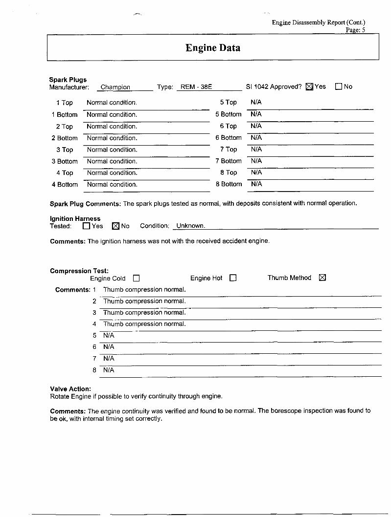
Spark Plugs Manufacturer: Champion Type: REM - 38E SI 1042 Approved? Yes 0 No
1 Top
1 Bottom
2 Top
2 Bottom
3 Top
3 Bottom
4 Top
4 Bottom
Normal condition.
Normal condition.
Normal condition.
Normal condition.
Normal condition.
Normal condition.
Normal condition.
Normal condition.
5 Top
5 Bottom
6 Top
6 Bottom
7 Top
7 Bottom
8 Top
8 Bottom
N/A
NIA
NIA
NIA
NIA
NIA
N/A
NIA
Spark Plug Comments: The spark plugs tested as normal, with deposits consistent with normal operation.
Ignition Harness Tested: Yes No Condition: Unknown.
Comments: The ignition harness was not with the received accident engine.
Compression Test: Engine Cold 0 Engine Hot 0 Thumb Method
Comments: 1 Thumb compression normal.
2 Thumb compression normal.
3 Thumb compression normal.
4 Thumb compression normal.
5 NIA
6 NIA
7 N I A
8 NIA
Valve Action: Rotate Engine if possible to verify continuity through engine.
Comments: The engine continuity was verified and found to be normal. The borescope inspection was found to be ok, with internal timing set correctly.
-
Engine Disassembly Report (Cont.) Page: 6
Engine Data
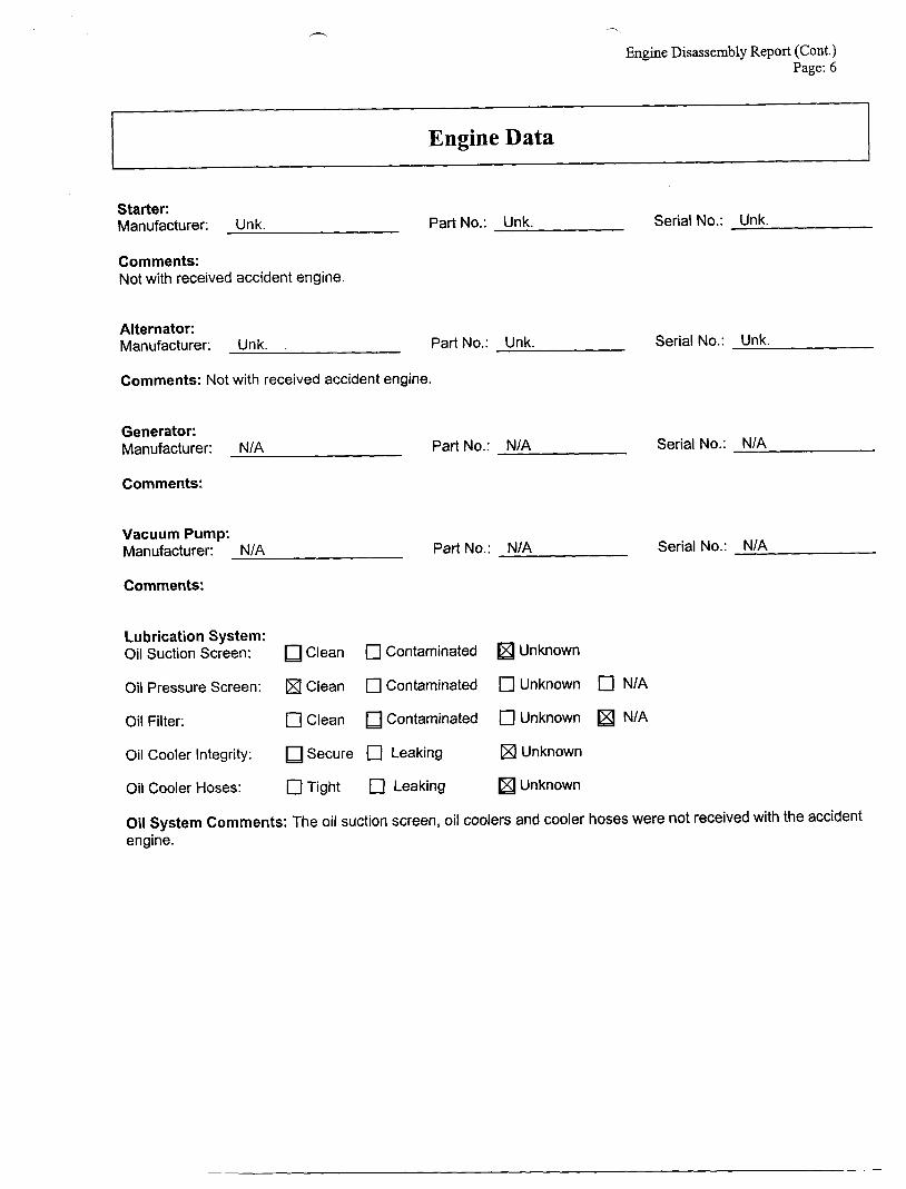
Starter: Manufacturer: Unk. Part No.: Unk. Serial No.: Unk.
Comments: Not with received accident engine.
Alternator: Manufacturer: Unk.
Comments: Not with received accident engine.
Part No.: Unk. Serial No.: Unk.
Generator: Manufacturer: N/A Part No.: N/A Serial No.: NIA
Comments:
Vacuum Pump: Manufacturer: N/A Part No.: NIA Serial No.: NIA
Comments:
Lubrication System: Oil Suction Screen: Clean 0 Contaminated Unknown
Oil Pressure Screen: (XI Clean 0 Contaminated 0 Unknown [zl N/A
Oil Filter: 0 Clean Contaminated 0 Unknown NIA
Oil Cooler Integrity: Secure 0 Leaking Unknown
Oil Cooler Hoses: 0 Tight c] Leaking Unknown
Oil System Comments: The oil suction screen, oil coolers and cooler hoses were not received with the accident engine.
Engine Disassembly Report (Cont.) Page: 7
Engine Data
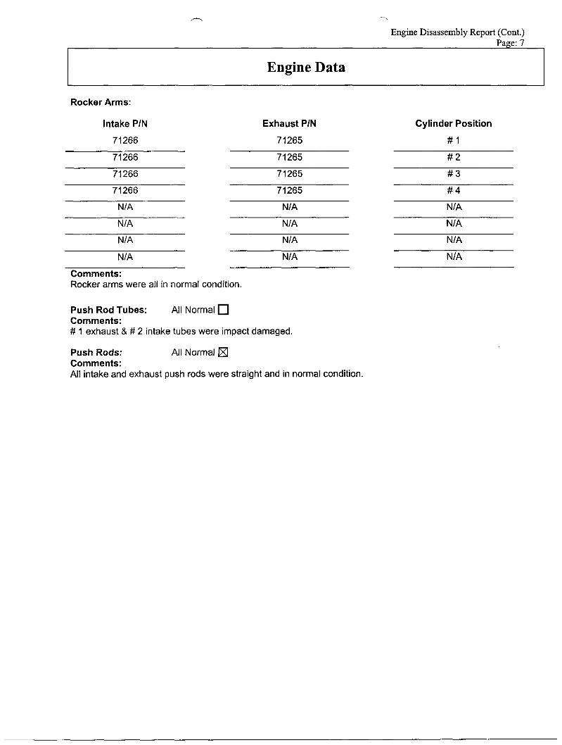
Rocker Arms:
Intake PIN Exhaust PIN Cylinder Position
71266 7 1265 # 1 ~
71 266
71266
71266
71 265
71265
71265
NIA NIA
NIA
NIA
# 2
# 3
# 4
NIA
NIA NIA
NIA
NIA NIA
Comments: Rocker arms were all in normal condition.
Push Rod Tubes: Comments: # 1 exhaust & # 2 intake tubes were impact damaged.
Push Rods: All Normal Comments: All intake and exhaust push rods were straight and in normal condition.
All Normal
NIA
NIA
- P
Engine Disassembly Report (Cont.) Page: 8
Engine Data
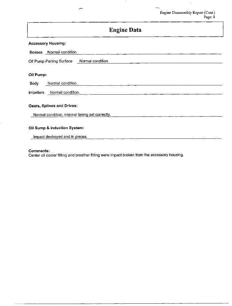
Accessory Housing:
Bosses Normal condition.
Oil Pump Parting Surface Normal condition.
Oil Pump:
Body Normal condition.
Impellers Normal condition.
Gears, Splines and Drives:
Normal condition, internal timing set correctly.
Oil Sump & Induction System:
Impact destroyed and in pieces.
Comments: Center oil cooler fitting and breather fitting were impact broken from the accessory housing.
0 -
Engine Disassembly Report (Cont.) Page: 9
I 1
Engine Data
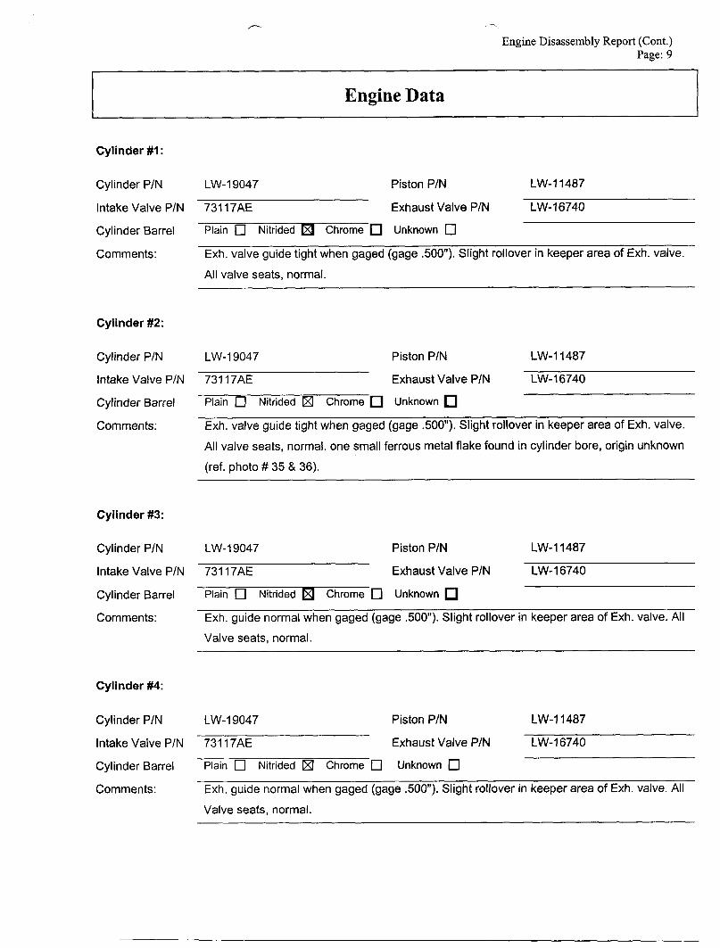
Cylinder #I :
Cylinder P/N
Intake Valve P/N
Cylinder Barrel
Comments:
LW-19047 Piston PIN LW-11487
731 17AE Exhaust Valve P/N LW-16740
Plain 0 Nitrided Chrome Unknown 0 Exh. valve guide tight when gaged (gage .SOO"). Stight rollover in keeper area of Exh. valve.
All valve seats, normal.
Cylinder #2:
Cylinder P/N LW-I 9047 Piston PIN LW-11487
Intake Valve P/N 731 17AE Exhaust Valve P/N LW-16740
Cylinder Barrel Plain 0 Nitrided Chrome Unknown
Comments: Exh. valve guide tight when gaged (gage 500"). Slight rollover in keeper area of Exh. valve.
All valve seats, normal. one small ferrous metal flake found in cylinder bore, origin unknown
(ref. photo # 35 & 36).
Cylinder #3:
Cylinder P/N LW-19047 Piston P/N LW-11487
Intake Valve P/N 731 17AE Exhaust Valve PIN LW-16740
Cylinder Barrel Plain 0 Nitrided Chrome 0 Unknown
Comments: Exh. guide normal when gaged (gage 500"). Slight rollover in keeper area of Exh. valve. All
Valve seats, normal.
Cylinder #4:
Cylinder P/N LW-19047 Piston P/N LW-11487
Intake Valve P/N 731 17AE Exhaust Valve P/N LW-16740
Cylinder Barrel Plain 0 Nitrided (XI Chrome 0 Unknown 0 Comments: Exh. guide normal when gaged (gage 500"). Slight rollover in keeper area of Exh. valve. All
Valve seats, normal.
Engine Disassembly Report (Cont.) Page: 10
I I
Engine Data
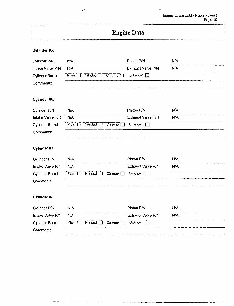
Cylinder #5:
Cylinder P/N N/A Piston PIN N/A
Intake Valve PIN N/A Exhaust Valve PIN N/A
Cylinder Barrel Plain 0 Nitrided Chrome 1 Unknown
Comments:
Cylinder #6:
Cylinder P/N N/A Piston P/N NIA -
Intake Valve P/N N/A Exhaust Valve PIN
Cylinder Barrel Plain 0 Nitrided 0 Chrome Unknown
NIA
Comments:
Cylinder #7:
Cylinder PIN NIA Piston P/N N/A
Intake Valve P/N NIA Exhaust Valve P/N N/A
Cylinder Barrel Plain 0 Nitrided 0 Chrome Unknown 0 Comments:
Cylinder #8:
Cylinder P/N N/A Piston P/N N/A
Intake Valve P/N N/A Exhaust Valve P/N N/A
Cylinder Barrel Plain 0 Nitrided Chrome 0 Unknown 0 Comments:
Engine Disassembly Report (Cont.) Page: 11
Engine Data
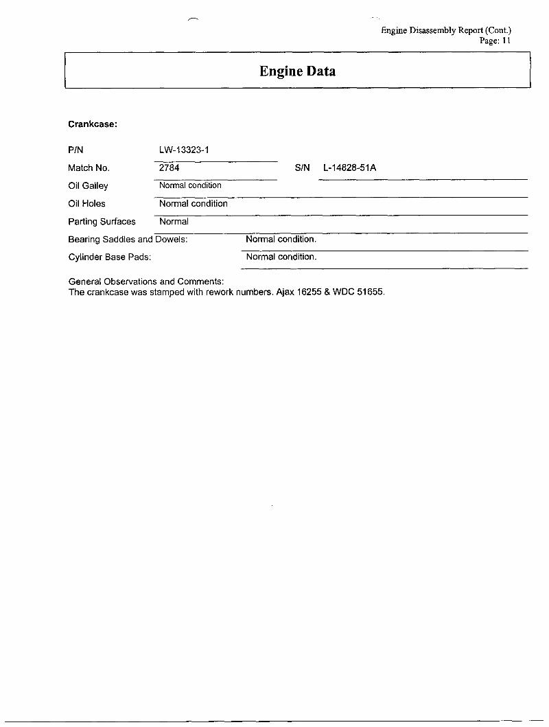
Crankcase:
P/N LW-13323-1 ~
Match No. 2784 ~ S/N L-14828-51 A
Oil Galley Normal condition
Oil Holes Normal condition
Parting Surfaces Normal
Bearing Saddles and Dowels: Normal condition.
Cylinder Base Pads: Normal condition.
General Observations and Comments: The crankcase was stamped with rework numbers. Ajax 16255 & WDC 51655.
Engine Disassembly Report (Cont.) Page: 12
Engine Data
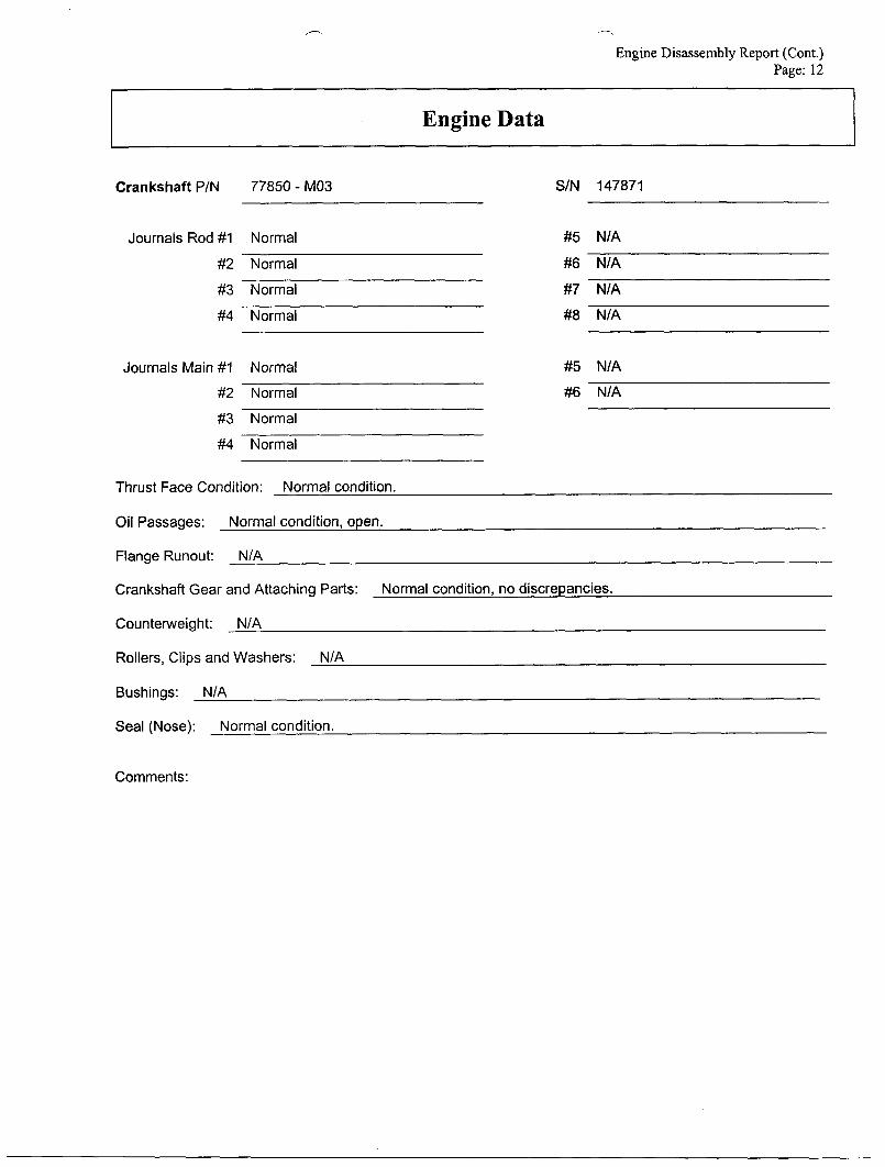
Crankshaft P/N 77850 - M03 S/N 147871
Journals Rod #1 Normal
#2 Normal
#3 Normal
#4 Normal
Journals Main #1 Normal
#2 Normal
#3 Normal
#4 Normal
#5 N/A
#6 N/A
#7 N/A
#8 N/A
#5 NIA
#6 N/A
Thrust Face Condition: Normal condition.
Oil Passages: Normal condition, open.
Flange Runout: NIA
Crankshaft Gear and Attaching Parts:
Counterweight: N/A
Rollers, Clips and Washers: N/A
Bushings: N/A
Seal (Nose): Normal condition.
Normal condition, no discrepancies.
Comments:
Engine Data
_- Engine Disassembly Report (Cont.)
Page: 13
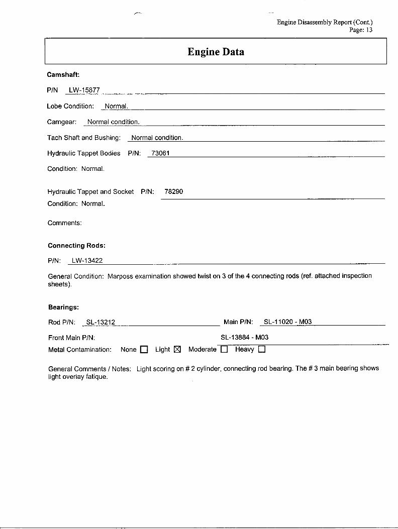
Camshaft:
P/N LW-15877
Lobe Condition: Normal.
Camgear: Normal condition.
Tach Shaft and Bushing: Normal condition.
Hydraulic Tappet Bodies P/N: 73061
Condition: Normal.
Hydraulic Tappet and Socket PIN: 78290
Condition: Normal.
Comments:
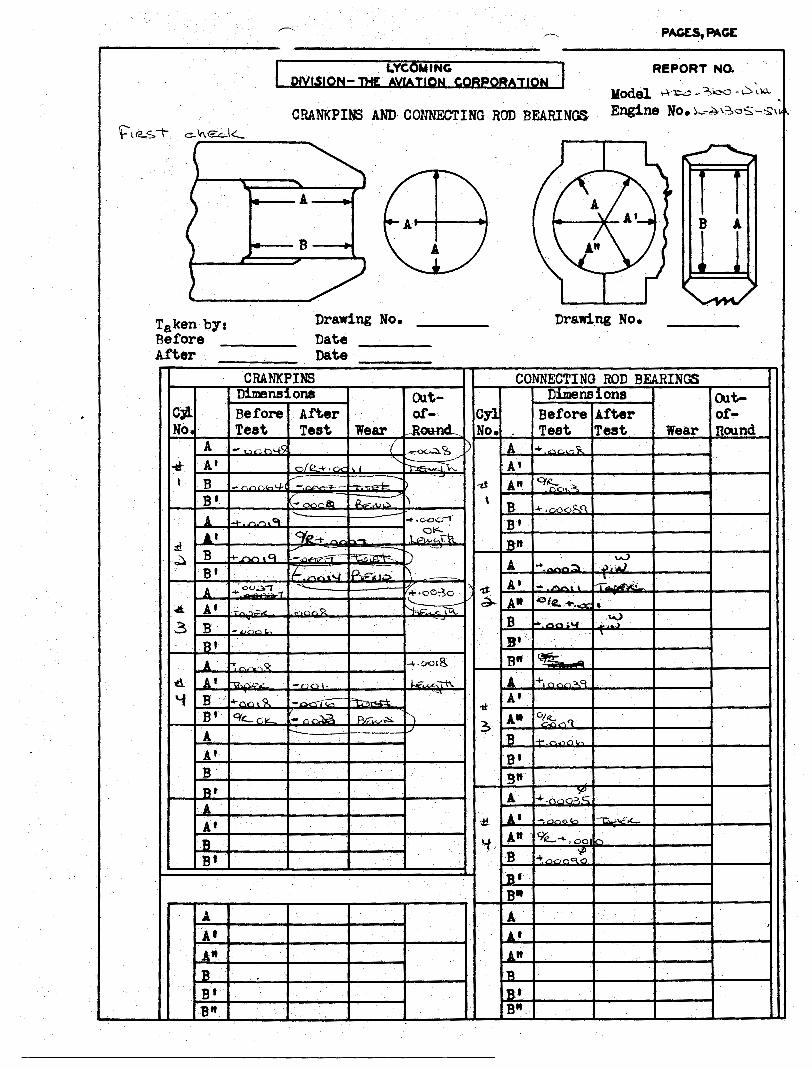
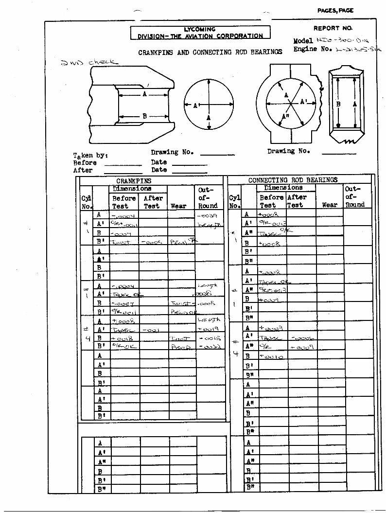
Connecting Rods:
P/N: LW-13422
General Condition: Marposs examination showed twist on 3 of the 4 connecting rods (ref. attached inspection sheets).
Bearings:
Rod P/N: SL-13212 Main P/N: SL-11020 - M03
Front Main P/N: SL-13884 - M03
Metal Contamination: None Light Moderate 0 Heavy 0
General Comments / Notes: Light scoring on # 2 cylinder, connecting rod bearing. The # 3 main bearing shows light overlay fatique.
n
Engine Disassembly Report (Cont.) Page: 14
Engine Data I-- ~~~ ~ ~ ~ ~
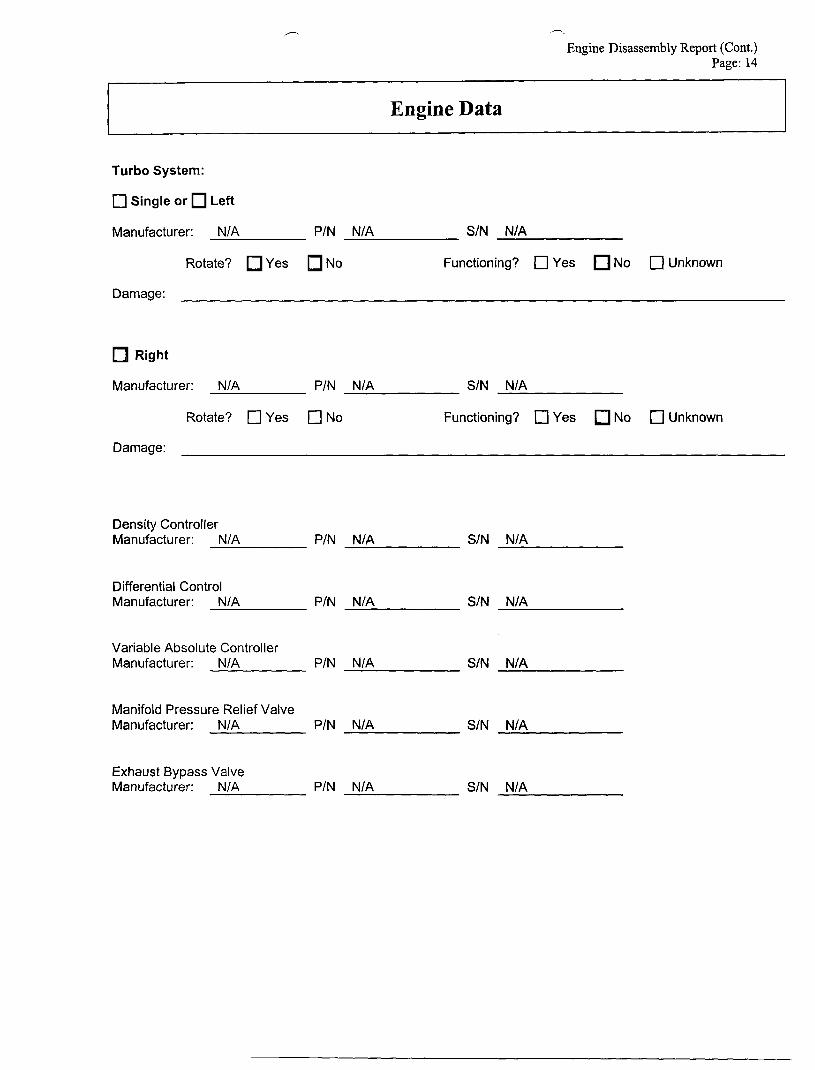
Turbo System:
0 Single or Left
Manufacturer: NIA PIN NIA S/N N/A
Rotate? Yes No Functioning? 0 Yes No 0 Unknown
Damage:
Right
Manufacturer: NIA PIN N/A S/N N/A
Rotate? c] Yes c] No Functioning? 0 Yes No c] Unknown
Damage:
Density Controller Manufacturer: NIA PIN NIA SIN NIA
Differential Control Manufacturer: NIA PIN N/A SIN NIA
Variable Absolute Controller Manufacturer: N/A PIN NIA SIN N/A
Manifold Pressure Relief Valve Manufacturer: NIA P/N NIA SIN NIA
Exhaust Bypass Valve Manufacturer: NIA PIN NIA SIN N/A
/--
Engine Disassembly Report (Cont.)
Engine Disassembly
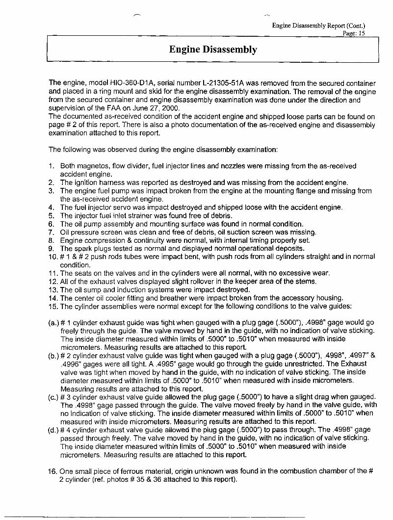
The engine, model HIO-360-D1A, serial number L-21305-51A was removed from the secured container and placed in a ring mount and skid for the engine disassembly examination. The removal of the engine from the secured container and engine disassembly examination was done under the direction and supervision of the FAA on June 27,2000. The documented as-received condition of the accident engine and shipped loose parts can be found on page # 2 of this report. There is also a photo documentation of the as-received engine and disassembly examination attached to this report.
The following was observed during the engine disassembly examination:
1. Both magnetos, flow divider, fuel injector lines and nozzles were missing from the as-received accident engine.
2. The ignition harness was reported as destroyed and was missing from the accident engine. 3. The engine fuel pump was impact broken from the engine at the mounting flange and missing from
the as-received accident engine. 4. The fuel injector servo was impact destroyed and shipped loose with the accident engine. 5. The injector fuel inlet strainer was found free of debris. 6. The oil pump assembly and mounting surface was found in normal condition. 7. Oil pressure screen was clean and free of debris, oil suction screen was missing. 8. Engine compression & continuity were normal, with internal timing properly set. 9. The spark plugs tested as normal and displayed normal operational deposits. 10. # 1 & # 2 push rods tubes were impact bent, with push rods from all cylinders straight and in normal
co nd i ti on. 11. The seats on the valves and in the cylinders were all normal, with no excessive wear. 12. All of the exhaust valves displayed slight rollover in the keeper area of the stems. 13. The oil sump and induction systems were impact destroyed. 14. The center oil cooler fitting and breather were impact broken from the accessory housing. 15. The cylinder assemblies were normal except for the following conditions to the valve guides:
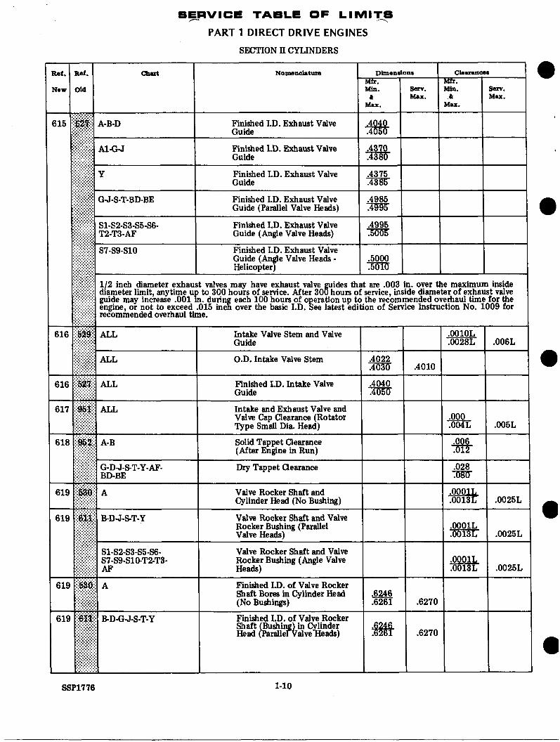
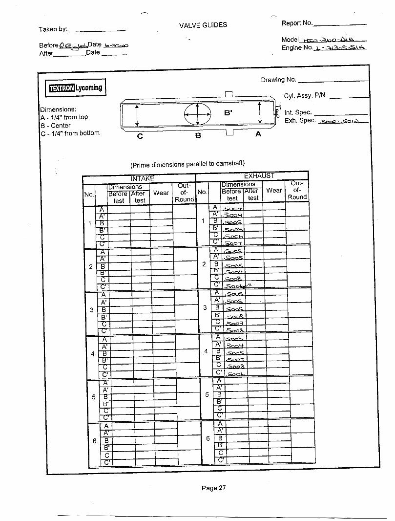
(a.) # 1 cylinder exhaust guide was tight when gauged with a plug gage ( S O O O ) , .4998” gage would go freely through the guide. The valve moved by hand in the guide, with no indication of valve sticking. The inside diameter measured within limits of .5000” to 501 0” when measured with inside micrometers. Measuring results are attached to this report.
(b.) # 2 cylinder exhaust valve guide was tight when gauged with a plug gage (.5000”), .4998, .4997” & .4996” gages were all tight. A .4995” gage would go through the guide unrestricted. The Exhaust valve was tight when moved by hand in the guide, with no indication of valve sticking. The inside diameter measured within limits of .5000” to Solo” when measured with inside micrometers. Measuring results are attached to this report.
(c.) # 3 cylinder exhaust valve guide allowed the plug gage (SOOO”) to have a slight drag when gauged. The .4998” gage passed through the guide. The valve moved freely by hand in the valve guide, with no indication of valve sticking. The inside diameter measured within limits of ,5000” to 501 0” when measured with inside micrometers. Measuring results are attached to this report.
(d.) # 4 cylinder exhaust valve guide allowed the plug gage (.5000) to pass through. The .4998” gage passed through freely. The valve moved by hand in the guide, with no indication of valve sticking. The inside diameter measured within limits of .5000” to 501 0 when measured with inside micrometers. Measuring results are attached to this report.
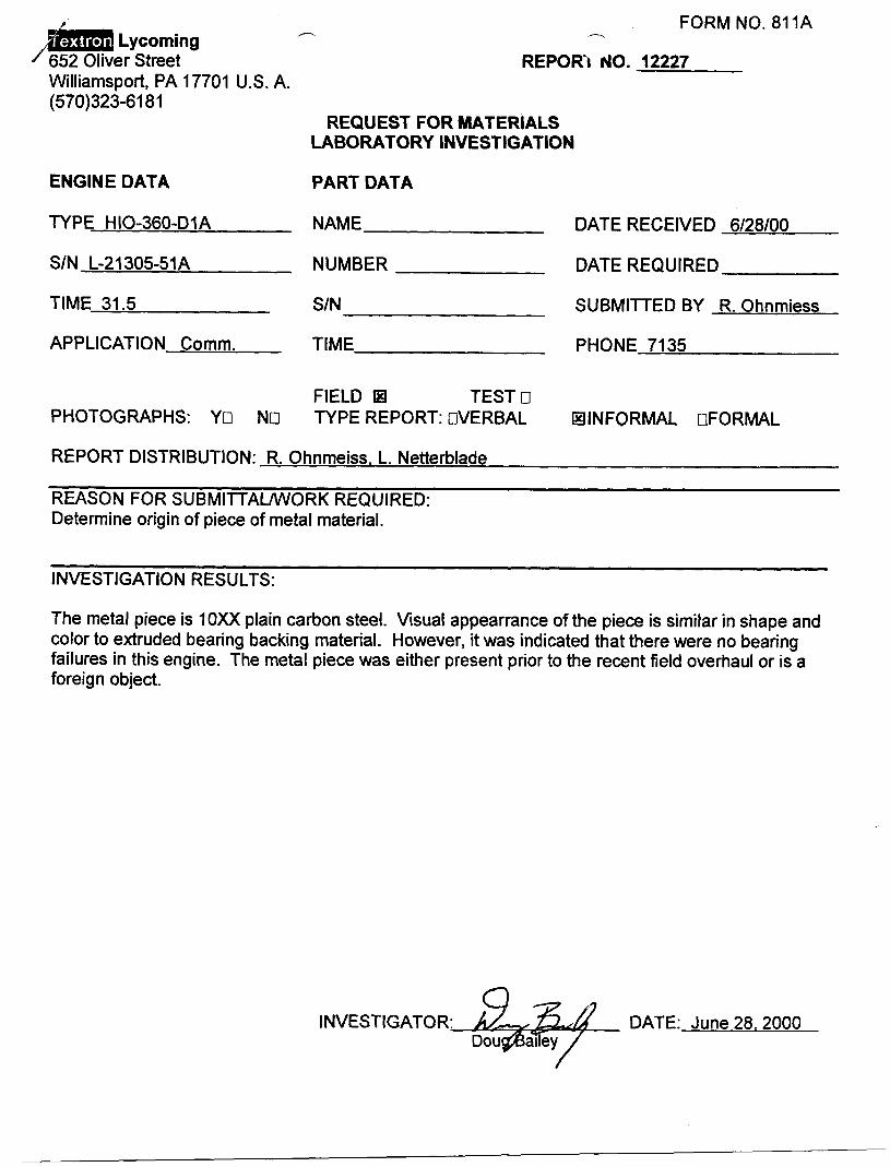
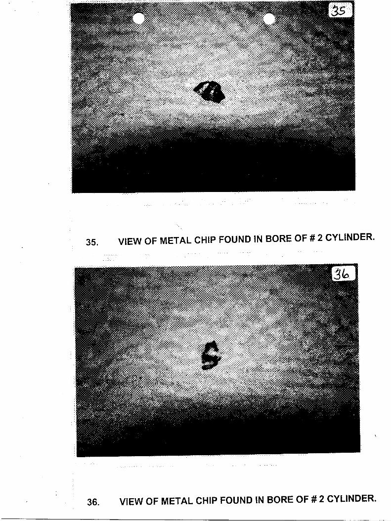
16. One small piece of ferrous material, origin unknown was found in the combustion chamber of the # 2 cylinder (ref. photos # 35 & 36 attached to this report).
h r-
Engine Disassembly Report (Cont.) Page: 16
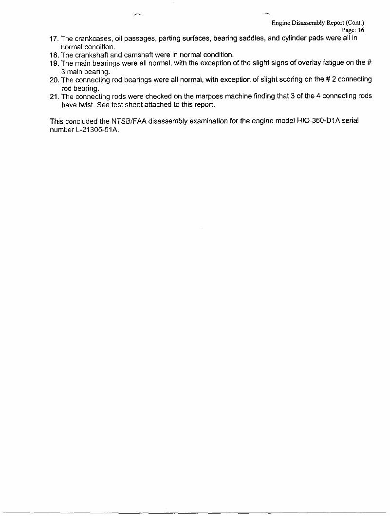
17. The crankcases, oil passages, parting surfaces, bearing saddles, and cylinder pads were all in
18. The crankshaft and camshaft were in normal condition. 19. The main bearings were all normal, with the exception of the slight signs of overlay fatigue on the #
20. The connecting rod bearings were all normal, with exception of slight scoring on the # 2 connecting
21. The connecting rods were checked on the marposs machine finding that 3 of the 4 connecting rods
normal condition.
3 main bearing.
rod bearing.
have twist. See test sheet attached to this report.
This concluded the NTSB/FAA disassembly examination for the engine model HIO-360-DIA serial number L-21305-51A.
+ M
Engine Disassembly Report (Cont.) Page: 17
Summary
The engine, serial number L-21305-51A was shipped as a new HIO-360-DIA model from TEXTRON Lycoming to Hughes Aircraft on October 26, 1979. There is no record of the engine returning to the Lycoming factory until after the mishap on October 15, 2000.
The engine L-21305-51A was field overhauled by Powerstroke Aviation, San Antonio, TX on February 16, 2000. The Field overhauled engine had a reported time of 31.5 hours at the time of the mishap. New replacement Lycoming cylinders were installed at the time of the engine overhaul.
The Lycoming cylinder & head assembly drawing number LW-19047 calls for an alignment pin of .4998” be used for the low limit diameter of the exhaust valve guide. Attached to this report is a letter to Lycoming from PCC explaining the actions taken since June of 1998 on the inside diameter of the exhaust valve guides.
The letter explains that the alignment pin used for the exhaust valve guide hone operation has a size equal to the guide inside diameter low limit of .5000”, rather than the drawing requirement of .4998”. The 5000” alignment pin is being used in the process on 100% of the assemblies LW-19047.
The engine and components were released and returned to Murray Huling, San Antonio, TX at the request of the NTSB IIC on June 28,2000.
END.
Engine Disassembly Report (Cont.) Page: 18
I I
Name and Address
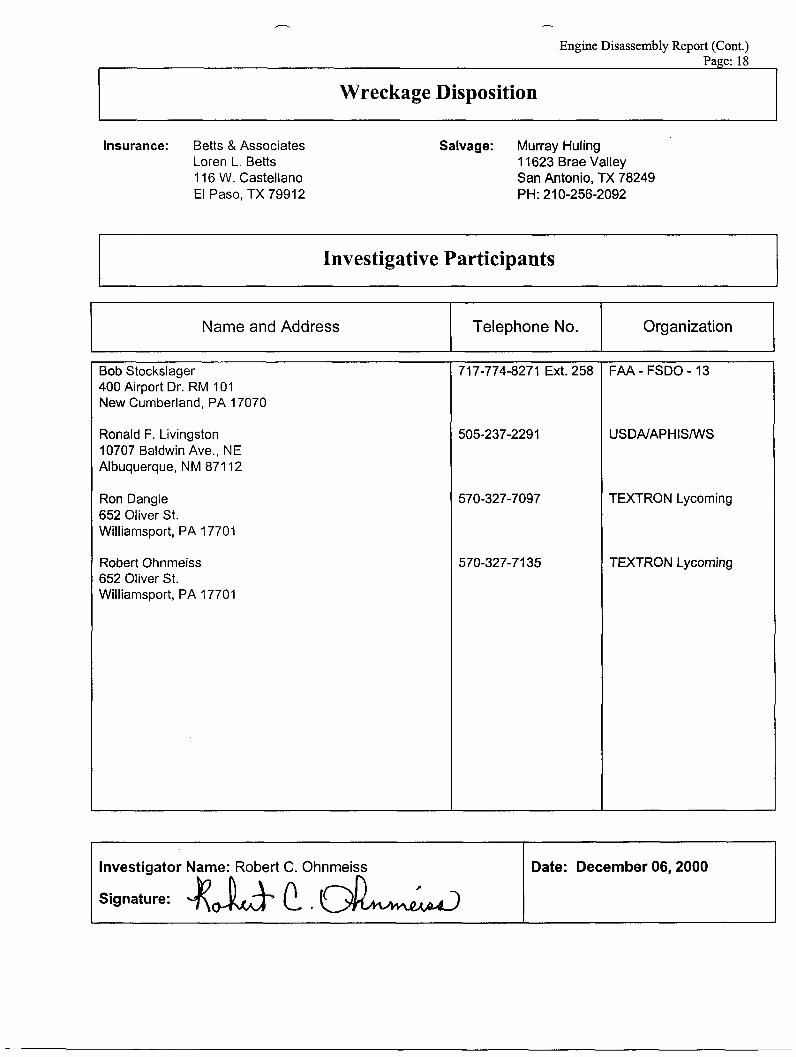
Wreckage Disposition
Telephone No. Organization
Insurance: Betts & Associates Loren L. Betts 116 W. Castellano El Paso, TX 79912
Investigator Name: Robert C. Ohnmeiss
Signature: $& t , &
Salvage: Murray Huling 1 1623 Brae Valley San Antonio, TX 78249 PH: 210-256-2092
Date: December 06,2000
Investigative Participants
Bob Stockslager 400 Airport Dr. RM 101 New Cumberland, PA 17070
Ronald F. Livingston 10707 Baldwin Ave., NE Albuquerque, NM 871 12
Ron Dangle 652 Oliver St. Williamsport, PA 17701
Robert Ohnmeiss 652 Oliver St. Williamsport, PA 17701
717-774-8271 EA. 258
505-237-2291
570-327-7097
570-327-71 35
FAA - FSDO - 13
USDNAPHISNVS
TEXTRON Lycoming
TEXTRON Lycoming
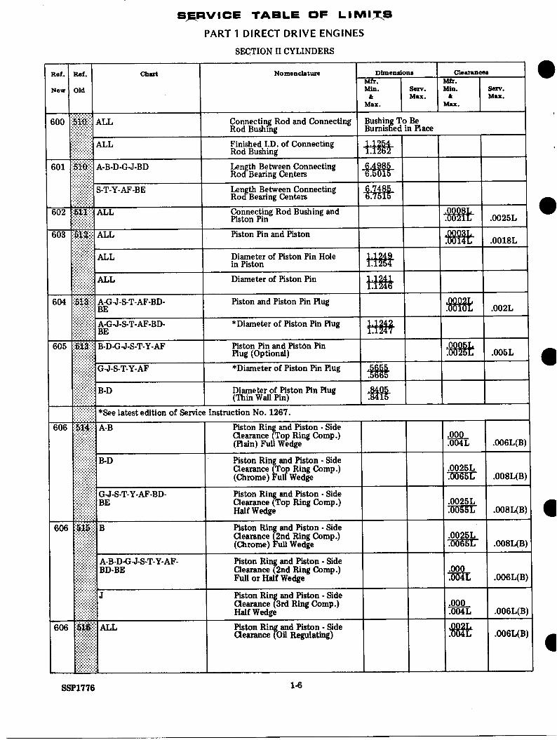
LYCOMING TABLE OF LIMITS EXCERPTS
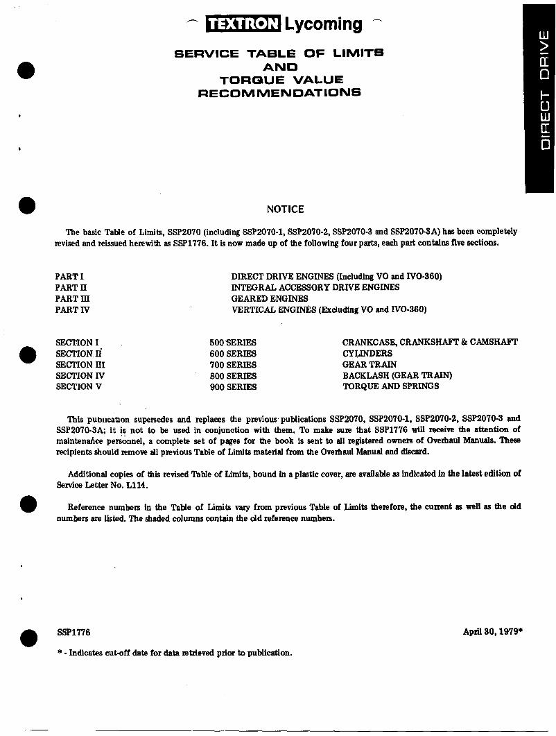
*:c ,--. n Lycoming
SERVICE TA6LE OF LIMITS AND
TORQUE VALUE RECOMMENDATIONS
NOTICE
The basic Table of Limits, SSP2070 (including SSP2070-1, SSP2070-2, SSP2070-3 and SSP20703A) has been completely revised and reissued herewith as SSP1776. It is now made up of the following four parts, each part contains five sections.
PART I PART II PART 111 PART IV
SECTION I SECTION n' SECTION II'I SECTION IV SECTION V
DIRECT DRIVE ENGINES (Including VO and IVO-360) INTEGRAL ACCESSORY DRIVE ENGINES GEARED ENGINES VERTICAL ENGImS (Excluding VO and IVO-360)
500 SERIES 600 SERIES 700 SERIES 800 SERIES 900 SERIES
CRANKCASE, CRANKSHAFT & CAMSHAFT CYLINDERS GEAR TRAIN BACKLASH (GEAR TRAIN) TORQUE AND SPRINGS
This publicanon supersedes and replaces the previous, publications SSP2070, SSP2070-1, SSP2070-2, SSP2070-3 and SSP2070-3A; it is not to be used in conjunction with them. To make sure that SSP1776 will receive the attention of maintendce personnel, a complete set of pages for the book is sent to all registered owners of Overhaul Manuals. These recipients should remove all previous Table of Limits material from the Overhaul Manual and discard.
Additional copies of this revised Table of Limits, bound in a plastic cover, are available as indicated in the latest edition of Service Letter No. L114.
Reference numbers in the Table of Limits vary from previous Table of Limits therefore, the current as well as the old numbers are listed. The shaded columns contain the d d reference numbers.
SSP1776
* - Indicates cut-off date for data letrieved prior to publication.
April 30,1979*
r‘- - INTRODUCTION
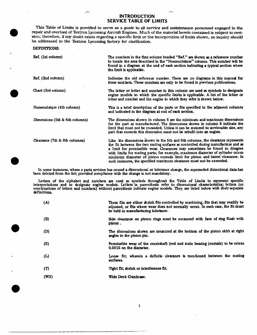
SERVICE TABLE OF LIMITS This Table of Limits is provided to serve as a *de to all service and maintenance personnel engaged in the
repair and overhaul of Textron Lycoming Aircraft Engines. Much of the material herein contained is subject to revi- sion; therefore, if any doubt exists regarding a specific limit o r the incorporation of limits shown, an inquiry should be addressed to the Textron Lycoming factory for clarification.
DEFINITIONS:
0
Ref. (1st column)
Ref. (2nd column)
Chart (3rd column) a Nomenclatyre (4th column)
Dimensions (5th & 6th columns)
Clearance (7th & 8th columns)
The numbers in the f i i t column headed “Ref.” are shown as a reference number to locate the area described in the “Nomenclature” column. This number will be found in a diagram at the end of each section indicating a typical section where the limit is applicable.
Indicates the old reference number. There are no diagrams in thii manual for these numbers. These numbers are only to be found in previous publications.
The letter or letter and number in this column are used as symbols to designate engine models to which the specific limits is applicable. A list of the letter or letter and number and the engine to which they refer is shown below.
This is a brief description of the parts or fits specified in the adjacent columns and indicated in the diagram at end of each section.
The dimensions shown in column 5 are the minimum and maximum dimensions for the part as manufactured. The dimensions shown in column 6 indicate the limit that must not be exceeded. Unless it can be restored to serviceable size, any part that exceeds this dimension must not be rebuilt into an engine.
Like the dimensions shown in the 5th and 6th columns, the clearance represents the fit between the two mating surfaces as controlled during manufacture and as a limit for permissible wear. Clearances may sometimes be found to disagree with limits for mating parts; for example, maximum diameter of cylinder minus minimum diameter of piston exceeds limit for piston and barrel clearance. In such instances, the specified maximum clearance must not be exceeded.
In some instances, where a parts revision has caused a dimensional or tolerance change, the superseded dimenional data has been deleted from the list; provided compliance with the change is not mandatory.
Letters of the alphabet and numbers are used as symbols throughout the Table of Limits to represent specific interpretations and to designate engine models. Letters in parenthesis refer to dimensional characteristics; letters (or combinations of letters and numbers) without parenthesis indicate engine models. They are listed below with their separate definitions.
These fits are either shrink fits controlled by machining, fits that may readily be adjusted, or fits where wear does not normally occur. In each caw, the fit must be held to manufacturing tolerance.
Side clearance on piston rings must be measured with face of ring flush with
The dimensions shown are measured at the bottom of the piston skirt at right angles to the piston pin.
Permissible wear of the crankshaft (rod and main bearing journals) to be minus 0.0015 on the diameter.
Loose fit; wherein a definite dearance is mentioned between the mating Surfaces.
piston.
(T)
CWD) Wide Deck Crankcaw.
Tight fit; shrink or interference fit.
i

Introduction
The illustrations shown are typical of the referenced limit or fit described in the Table and in no instance are these illustrations intended to represent a specific part or engine model unless specified. Also, the terms used to designate cylinder, piston and ring materials such as “nitride, chrome, half-wedge” are more fully explained in the latest edition of Service Instruction No. 1037.
0
CHART
A A1 B B1 D BD G G1
G2 J Y
s1 s2 53 s4
‘ 6
PART I DIRECT DRNE ENGINES (Including VO and IVO-360)
MODELS
0-235 6235-F, 6, -K, -L 6290 0-290-D2 0435-A 6320-H (76 Series)
0,IO-320 With Gov. at Front 0, IO, LIO, AEIO-320
(0-320-E1F, -ElJ, -DlF & IO-320-D1B) AIO-320 0-340 vo, IVO-360 0, IO, LIO, HIO, LHIO, TO, TIO, AEIO-360 TQ-360 AIO-360 TIO-360 6360-A With Gov. at Front (6360-A1H, -AlLD)
CHART
55 s6
\ 57 ss s 9 s10 T T1
n
T3
T4 AF BE
MODELS
IO, LIO-360-A, C (Angle Valve) IO, LI0-360-A, C With Gov. at Front (IO, LIO-360ClE6 & 10-360-AlIX) HI0-360-D HIO-360-B HI0-360-C, -E HI0-360-A 0, IO, LIO, AEIO, TIO, LTIO-540 Od4OC, -H & IO-54O-N, -R (Large Mains - Parallel Valve)
(Angle Valve)
-F, J, -N, -R (Large Mains - Angle
IO-540-A, -B, -E, 6, -P
IO-54O-K, -M, 4; “IO, LT’IOd40-&
Valve) TIO-5404, -E, 43, -H 10-720 0, LO-360-E (76 Series)
NOTE: In “Chart” column, a number appearing after a letter shows exception to the basic model.
ii
Ref.
New
- 500
Rst.
Old
50C
7
503
chut
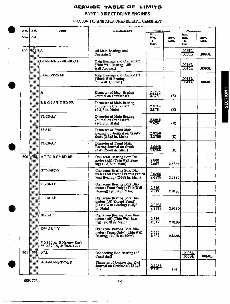
S P V I C E TABLE OF LIMIW
PART 1 DIRECT DRIVE ENGINES
SECTION I CRANKCASE, CRANKSHAFT, CAMSHAFT
Nomenclature dim en do^ CbUuN
Mfr. Mb. Min. 8an. Mia.
& Mu. & Mu. Mu.
Main Bearings and Crankshaft (Thin Wall Bearing - .09 Wall Approx.)
Main Bearings and Crankshaft (Thick Wall Bearing - .16 Wall Approx.)
Diameter of Maii Bearing Journal on Crankshaft
Diameter of Main Bearing Journal on Crankshaft
Diameter of Maii Bearing Journal on Crankshaft
Diameter of Front Main Bearing on Journal on Crank-
Diameter of Front Main Bearin Journal on Crank-
(2-3/8 in. Main)
(2-5/8 in. Main)
shaft (2-3/8 in. Main)
shaft (%-5/8 in. Main)
All Maii Bearings and Crankshaft
I * %!E-
2.3735 ?m?r (E)
mnr (E)
-!mK (E)
2.3760 (E) - (E)
2.3745
2.6245
2.3750
2.6245
Crankcase Bearine Bore Dia-
Crankcase Bearing Bore Dia- meter (All) (Thin Wall Bear- ing) (2-3/8 in. Main)
2.566 I 2.567 1 2.56851
l
Crankcase Bearing Bore Dia- meter (All Except Front) (l%ick Wall Bearing) (2-3/8 in. Main) 1 2.6875 I 2.68901
2.6865
Crankcase Bearing Bore Dia- meter (Front Only) (Thin Wall Bearing) (2-3/8 in. Main)
Crankcase Bearing Bore Dia- meter (Front Only) (Thin Wall Bearing) (25/8 in. Main)
2.818 1 2.817 1 2.81851
2.566 2.567 2.5685
Connecting Rod Bearing and Crankshaft Diameter of Connecti Rod Journal on Crmkshaf82-1/8 in.)
meters (All Excect Front) (Thick Wall Bearing) (2-5/8 2.9365 in. Maid I 2.9375 I 2.93901
* 2.1235 mx- (E)
Crankcase Bearing Bore Dia-
ing) (2-5/8 in. Main) meter (All) (Thin Wall Bear- 2.816 1 2.817 [ 2.81851
serv. Mu.
,006OL
,006OL
.0050L
.0050L
SSP1776 1-1
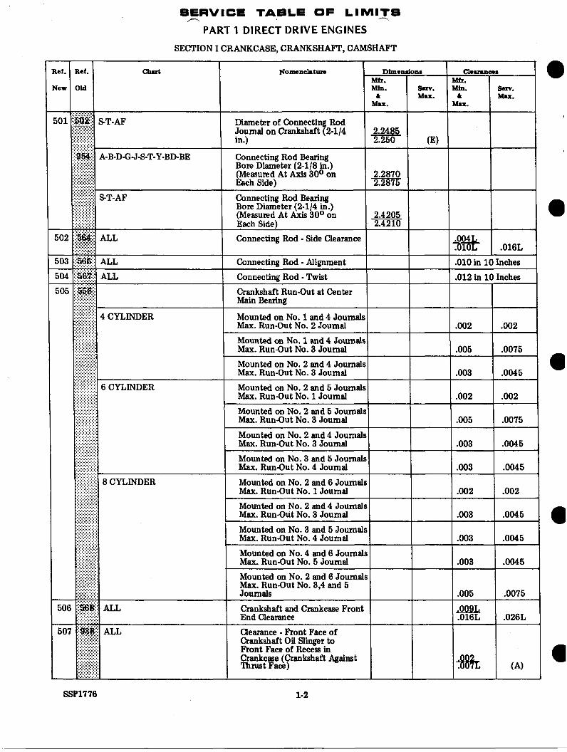
SERVICE TABLE OF LIMITS r'\ -
PART 1 DIRECT DRIVE ENGINES SECTION I CRANKCASE, CRANKSHAFT, CAMSHAFT
0
Mounted on No. 3 and 5 Journals
Clearance - Front Face of Crankshaft 01 Singer to Front Face of Recess in Crankcase (Crankshaft Against Thrust Face) * (A)
SSP1776 1-2
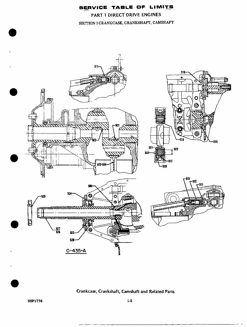
SEIIRVICE TABLE OF LIMIT-S
PART 1 DIRECT DRIVE ENGINES
SECTION I CRANKCASE, CRANKSHAFT, CAMSHAFT
SSP1776
0-435-A
Crankcase, Crankshaft, Camshaft and Related Parts
1-5
SXRVICE TABLE OF LlMlXS
PART 1 DIRECT DRIVE ENGINES
SECTION 11 CYLINDERS
SSP1776 1-6
I .006L(B)
.008L( B)
.008L(B)
.008L( B)
.006L( B)
.006L(B)
.006L(B)

SFRVICE TABLE OF LIMIXS
PART 1 DIRECT DRIVE ENGINES SECTION I1 CYLINDERS
I
Dimendom Cbarrnce8
Max. lax. Max.
O.D. Exhaust Valve Guide ,6267 ,6272 I I I I
O.D. Exhaust Valve Guide ,6638 - I I
O.D. Exhaust Valve Guide ,6958 I I I
I.D. Exhaust Valve Guide Hole in Cylinder Head
I.D. Exhaust Valve Guide Hole in Cylinder Head
I.D. Exhaust Valve Guide Hole in Cylinder Head
,6247 .6257
.6613 = I I I.D. Exhaust Valve Guide Hole in Cylinder Head
.6933 3 x 4 3 1 I
Intake Valve Guide and Cylinder Head
O.D. Intake Valve Guide .5938
I.D. Intake Valve Guide Hole in Cylinder Head
Exhaust Valve Stem and Valve Guide
.0020L I .0038L- I (A)
.004OL I .oo6oL- 1 (A) Exhaust Valve Stem and Valve Guide (Parallel Valve Heads)
Exhaust Valve Stem and Valve Guide
Exhaust Valve Stem and Valve Guide (Angle Valve Heads)
.0035L 1 I (A)
.0037L (A)
.0035L 1 I I (A)
Exhaust Valve Stem and Valve Guide (An e Valve Heads - Helico pterr
O.D. Exhaust Valve Stem
O.D. Exhaust Valve Stem
0 .D . 'EA aus t Valve Stem
O.D. Exhaust Valve Stem (Parallel Valve Heads) 1 .4935 1 .4915 I O.D. Exhaust Valve Stem (Angle Valve Heads)
applicable only to inconel or nimonic valves.
SSP1776 1-9
SEIRVICE TAELE OF LIMITS
PART 1 DIRECT DRIVE ENGINES ----.
Dimendons Mfr. Min. 8sn.
& Mu. Mu.
I , I:.:.:... ....... .......
115 ‘sg$$ ......... A-B-D Finished I.D. Exhaust Valve ,4040 .4050 ............... ................ ............... .............. ........ ............... ...............
............... Guide
Finished I.D. Exhaust Valve Guide
....... Finished I.D. Exhaust Valve
..... .. % 1
....... ........ ....... ........ ...... ........ ....... ........ ....... ........ ....... .......
Al-GJ ................
.4375 ;:::::::::::::: y
SECTION 11 CYLINDERS
Ch4NLiCO. Mfr. Min. serv.
& Mu. Mu.
.et. Bbf. CM Nomenclature Dimendons
rea OM Min. 8sn. & Mu.
Mfr.
Mu. -_ :.:.:*.. ....... ....... 115 ‘sg$$ ......... A-B-D Finished I.D. Exhaust Valve ,4040
.4050 ............... ................ ............... .............. ........ ............... ............... Guide
Guide
Finished I.D. Exhaust Valve .4375
..... .. ............... Finished I.D. Exhaust Valve Al-GJ
:::::::::::::: y
1
....... ........ ....... ........ ...... ........ ....... ........ ....... ........ ....... ....... ....... ................
Nomenclature Ch4NLiCO. Mfr. Min. serv.
& Mu. Mu.
CM
I
I
.et.
rea
Bbf.
OM
I Guide [!::?:::::::::I
Sl-P2-S3-S5-S6- T2-T3-AF
I I 1.4385 I
1 Finished I.D. Exhaust Valve Guide (Angle Valve Heads)
........ .:.:.:.:.:.:.:, .4385 Guide
.6246 -
.6261
....... ....... ....... ....... ....... ....... GJ-S-T-BD-BE ....... ....... ....... ....... ....... .......
.OOlOL I I .006L
%E Finished I.D. Exhaust Valve Guide (Parallel Valve Heads)
.4010 I I
” ....... ........ ....... ........ ....... ....... I I
..... ............... ...... \* . S7-S9-S10 Finished I.D. Exhaust Valve ........ ....... ........ ....... ........ ....... ........ ....... Guide (An e Valve Heads - .5000 .5010
1/2 inch diameter exhaust valves may have exhaust valve ides that are .003 +. oyer the maximum inside guide may increase .001 111. durin each 100 hours of o eration up to the recommended ovemaul tune for the
........ ........ ....... Helicopter$
........ ....... engine, or not to exceed .015 incf over the basic I.D. 8ee latest edition of Semce Instruction No. 1009 for
....... ........ ....... ........ ....... ........ ....... ........ ....... ........ ............... ....... ............... ....... ....... .:.:.:.:.:.:.’ ........ &?meter limit, anytime up to 300 hours of service. After 3O~hours of service, inside dlameter of exhaust valve ....... ........ ........ ....... ........ ....... ........ ............... ....... recommended overhaul time. ........
1 .ooo I .005L
.OoOlL
.OoOlL
.0013L .0025L
.6270
.6270
SSP1776 1-10
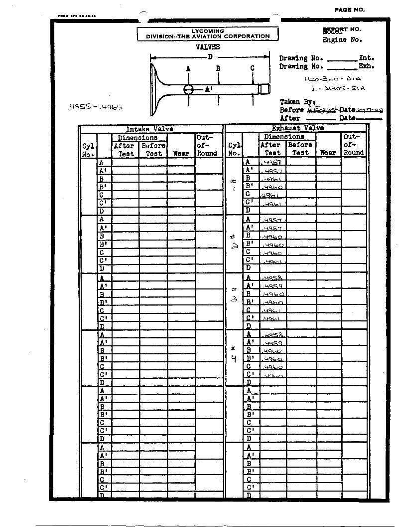
PARTS MEASUREMENT DATA
Taken by:
I -Lycoming I n / Cyl. Assy. PIN
B' .$ Int. Spec. - Dimensions: A - 1/4" from top B - Center
Exh. Spec. a-m -.do I 3 / \ U A C - 1/4" from bottom C B
B e f o r e e D a t e (n-2r-Q After Date
VALVE GUIDES
~
Report No.
Drawing NO.
Prime dimensions parallel to camshaft)
Page 27
?AGE NO. 9
f l r0.u ... .m.m...
LYCOM I N O Btb88f' No. Engine No. DIVISION--THE AVIATION CORPORATION
VALVES
Drawlng No. Drawing No. Taken by: Before Date Af
MATERIALS LABORATORY REPORT
FORM NO. 811A ,---x
652 Oliver Street Williamsport, PA 17701 U.S. A. (570)323-6181
ENGINE DATA
TYPE HIO-360-D1A
S/N L-21305-51A
TIME 31.5
AP P LI CAT1 0 N Co mm .
PHOTOGRAPHS: YO NO
REPOR’I E10. 12227
REQUEST FOR MATERIALS LABORATORY INVESTIGATION
PART DATA
NAME DATE RECEIVED 6/28/00
NUMBER DATE REQUIRED
SIN SUBMITTED BY R. Ohnmiess
TIME PHONE 7135
FIELD El TEST 0 TYPE REPORT: OVERBAL EIINFORMAL UFORMAL
REPORT DISTRIBUTION: R. Ohnmeiss. L. Netterblade
REASON FOR SUBMITTAUWORK REQUIRED: Determine origin of piece of metal material.
INVESTIGATION RESULTS:
The metal piece is IOXX plain carbon steel. Visual appearrance of the piece is similar in shape and color to extruded bearing backing material. However, it was indicated that there were no bearing failures in this engine. The metal piece was either present prior to the recent field overhaul or is a foreign object.
INVESTIGATOR DATE: June 28,2000
35. VIEW OF METAL CHIP FOUND IN BORE O F # 2 CYLINDER.
36. VIEW OF METAL CHIP FOUND IN BORE OF # 2 CYLINDER.