Embed Size (px)
Citation preview
Graduate Theses, Dissertations, and Problem Reports
2005
Aircraft intercom system design for project oculus Aircraft intercom system design for project oculus
Jay Paul Wilhelm West Virginia University
Follow this and additional works at: https://researchrepository.wvu.edu/etd
Recommended Citation Recommended Citation Wilhelm, Jay Paul, "Aircraft intercom system design for project oculus" (2005). Graduate Theses, Dissertations, and Problem Reports. 4204. https://researchrepository.wvu.edu/etd/4204
This Thesis is protected by copyright and/or related rights. It has been brought to you by the The Research Repository @ WVU with permission from the rights-holder(s). You are free to use this Thesis in any way that is permitted by the copyright and related rights legislation that applies to your use. For other uses you must obtain permission from the rights-holder(s) directly, unless additional rights are indicated by a Creative Commons license in the record and/ or on the work itself. This Thesis has been accepted for inclusion in WVU Graduate Theses, Dissertations, and Problem Reports collection by an authorized administrator of The Research Repository @ WVU. For more information, please contact [email protected].

Aircraft Intercom System Design for Project Oculus
By
Jay Paul Wilhelm
Thesis submitted to the College of Engineering and Mineral Resources
at West Virginia University in partial fulfillment of the requirements
for the degree of Master of Science
in Electrical Engineering
Approved by
Dr. Roy S. Nutter, Jr., Committee Chairperson Dr. James E. Smith
Dr. Powsiri Klinkhachorn Lane Department of Computer Science and Electrical Engineering
Morgantown, West Virginia 2005
Keywords: C-130, Aircraft Intercom, Project Oculus

Abstract
Aircraft Intercom System Design for Project Oculus
Jay Paul Wilhelm
Project Oculus is an ongoing development project at WVU that aims to create a quick and easy sensor platform for deployment on the C-130 aircraft. Because this platform will be operated inside the noisy cargo bay of the C-130, an intercom system needed to be designed in the operator station of Project Oculus that would allow for different types of headsets and future expandability.
An intercom system was designed, constructed, and tested that uses military and civilian headsets to communicate both internally for Project Oculus and externally to the C-130 crew and provides support for a headset to be connected externally of the operator station.

iii
Acknowledgements I would like to thank WVU Center for Industrial Applications (CIRA) for funding this project and this thesis. Most of all I would like to thank Dr. Roy Nutter and Dr. James Smith for allowing me to work on an exciting and ever developing project. Also Franz (Andy) Pertl, Emily Pertl, Zenovy Wowczuk, Gerald (Bear) Angle, and Dr. Klinkhachorn for keeping on my case and making sure things got done.

iv
Table of Contents Acknowledgements............................................................................................................ iii Table of Contents............................................................................................................... iv List of Figures.................................................................................................................... vi List of Tables ..................................................................................................................... ix Chapter 1. Introduction ....................................................................................................... 1
1.1. Project Oculus..................................................................................................... 1 1.2. Intercoms............................................................................................................. 6
Chapter 2. Statement of the Problem.................................................................................. 8 Chapter 3. Aircraft Intercoms ............................................................................................. 9
3.1. Different Types of Intercoms............................................................................ 10 3.1.1. Military Intercoms .................................................................................... 11 3.1.2. Civilian Intercoms..................................................................................... 11
3.2. Headsets and their impedances ......................................................................... 11 3.3. Microphones ..................................................................................................... 14
Chapter 4. Intercom Design for Project Oculus................................................................ 17 4.1. Intercom System ............................................................................................... 17 4.2. Intercom Design................................................................................................ 21 4.3. Intercom Testing ............................................................................................... 23
4.3.1. Methods of Calculation............................................................................. 24 4.3.2. Headset tests.............................................................................................. 27 4.3.3. Impedance Matching Circuitry Tests........................................................ 35 4.3.4. Sound Level Tests..................................................................................... 49 4.3.5. Dynamic Microphone Amplifier Circuit Tests ......................................... 51 4.3.6. Overall Tests Conclusion.......................................................................... 56
4.4. Conclusion ........................................................................................................ 57 4.5. Future Work ...................................................................................................... 57
Works Cited ...................................................................................................................... 58 Appendix A Custom Impedance Matching Circuit .......................................................... 60
A.1 Headset Impedance Matching Circuit Design .................................................. 60 A.1.1 Schematic of Headphone Buffer............................................................... 63
A.2 Microphone Amplifier ...................................................................................... 63 A.2.1 Microphone Amplifier Description........................................................... 63 A.2.2 Schematic of the Microphone Circuit ....................................................... 65
A.3 Complete Circuit Description ........................................................................... 67 A.4 Schematic and Layout of Impedance Matching Circuit ................................... 73
A.4.1 Schematic.................................................................................................. 73 A.4.2 Layout ....................................................................................................... 74
A.5 List of Inputs and Outputs................................................................................. 76 A.6 Parts list for PCB .............................................................................................. 77 A.7 Assembled PCB ................................................................................................ 78 A.8 Various Measured Frequency Responses and other Tests................................ 78
Appendix B Project Oculus Intercom Schematics............................................................ 79
v
B.1 Pilot and Co-Pilot Positions Schematic ............................................................ 79 B.2 Middle Position Schematic ............................................................................... 80 B.3 Intercom Tie Line Connections ........................................................................ 81 B.4 C-130 Intercom Connection.............................................................................. 82 B.5 Panel Layout of Project Oculus Intercom System ............................................ 83 B.6 Parts List for Intercom System ......................................................................... 84 B.7 Description of NAT AA83................................................................................ 84 B.8 NAT AA83 Specifications................................................................................ 85 B.9 Description of NAT AA36-100 ........................................................................ 86 B.10 NAT AA36-100 Settings .................................................................................. 87 B.11 Flightcom Denali ANR & Civilian Headset Specifications [18]...................... 88 B.12 Military Headset Specifications........................................................................ 88 B.13 Headset Plugs.................................................................................................... 89

vi
List of Figures Figure 1 - C-130 in flight .................................................................................................... 1 Figure 2 - Sensor Pallet with sensor pod extended [4] ....................................................... 2 Figure 3 - Operator Station Pallet [2] ................................................................................. 3 Figure 4 - Standardized sensor pallet system concept diagram [2] .................................... 4 Figure 5 - Pendant Control.................................................................................................. 5 Figure 6 - Various Headset Speaker configurations ......................................................... 13 Figure 7 - Dynamic Microphone....................................................................................... 14 Figure 8 - Electret Condenser Microphone....................................................................... 15 Figure 9 - Flightcom Denali ANR .................................................................................... 16 Figure 10 - Flightcom Denali ANR Military .................................................................... 16 Figure 11 - Concept Headset Selection Device per Operator Station............................... 19 Figure 12 - Basic Block Diagram of Intercom Connections............................................. 22 Figure 13 - Intercom Testing Tree .................................................................................... 23 Figure 14 - Power Triangle ............................................................................................... 26 Figure 15 - AA83 Intercom Test Setup using Microphone Input..................................... 28 Figure 16 - Voltage vs Frequency AA83 Microphone Input............................................ 29 Figure 17 - Frequency Response of AA83 using 150 & 300 Ω Speaker Loads ............... 29 Figure 18 - Calculated Voltage Gain of AA83 with 150 & 300 Ω Speaker Loads .......... 30 Figure 19 - Calculated Apparent Power @ 125mVrms to 150 & 300 Ω Speaker Loads . 30 Figure 20 - Calculated Apparent Power @ 500mVrms using 150 & 300 Ω Speaker Loads........................................................................................................................................... 31 Figure 21 - AA83 Intercom test Setup using Music Input................................................ 32 Figure 22 - Voltage vs Frequency to AA83 Music Input ................................................. 32 Figure 23 - Frequency Response of AA83 using 150 & 300 Ω Speaker Loads ............... 33 Figure 24 - Calculated Voltage Gain of AA83 using 150 & 300 Ω Speaker Loads......... 33 Figure 25 - Calculated Apparent Power @ 900 mVrms using 150 & 300 Ω Speaker Loads................................................................................................................................. 34 Figure 26 - Calculated Apparent Power @ 1.5 Vrms using 150 & 300 Ω Speaker Loads34 Figure 27 - Impedance box testing setup with AA83 mic input ....................................... 36 Figure 28 - Voltage input to AA83 (mic i/p) with box ..................................................... 36 Figure 29 - Frequency Response of AA83 (mic i/p) with box ......................................... 37 Figure 30 - Frequency Response of box with AA83(mic i/p) .......................................... 37 Figure 31 - Calculated Voltage gain of AA83(mic i/p), box, & overall gain ................... 38 Figure 32 - Calculated Apparent Power to 150 Ω HS from box & AA83(mic i/p) @ 125mVrms......................................................................................................................... 38 Figure 33 - Calculated Apparent Power to 150 Ω HS from box & AA83(mic i/p) @ 500mVrms......................................................................................................................... 39 Figure 34 - Impedance box testing setup with AA83 music input ................................... 39 Figure 35 - Voltage input to AA83 (music i/p) with box ................................................. 40 Figure 36 - Frequency Response of AA83 (music i/p) with box...................................... 40 Figure 37 - Frequency Response of box with AA83(music i/p)....................................... 41 Figure 38 - Calculated Voltage gain of AA83(music i/p), box, & overall gain ............... 41

vii
Figure 39 – Calculated Apparent Power to 150 Ω HS from box & AA83 Music I/P ...... 42 Figure 40 - Calculated Apparent Power to 150 Ω HS from box & AA83 Music I/P ....... 42 Figure 41 - Impedance Box Individual Testing Setup ...................................................... 43 Figure 42 - Voltage input from the Signal Generator to the Box ..................................... 43 Figure 43 - Frequency Response of the impedance box ................................................... 44 Figure 44 - Frequency Response of the impedance box ................................................... 44 Figure 45 - Calculated Apparent Power to the 150 Ω HS from the box........................... 45 Figure 46 - No Power impedance box testing setup ......................................................... 46 Figure 47 - Input to AA83(mic i/p) & Box without power............................................... 46 Figure 48 - Frequency Response of AA83(mic i/p) & Box without power...................... 47 Figure 49 - Calculated Voltage Gain of AA83(mic i/p) & Box without power ............... 47 Figure 50 - Calculated Apparent power to 150 Ω HS from AA83(mic i/p) & Box W/O power................................................................................................................................. 48 Figure 51 - Sound Level Test Setup ................................................................................. 50 Figure 52 - Sound level test graph .................................................................................... 50 Figure 53 – Voltage Reduction Circuit ............................................................................. 52 Figure 54 - Microphone Circuit Input Response Setup .................................................... 52 Figure 55 - Microphone Test Signal Generator Output .................................................... 53 Figure 56 - Microphone Test Reducer Output.................................................................. 53 Figure 57 - Microphone Test Impedance Box Output ...................................................... 54 Figure 58 – Calculated Voltage Gain of Reducer............................................................. 54 Figure 59 - Calculated Voltage Gain of Box .................................................................... 55 Figure 60 - Calcualted Overall Voltage Gain of Reducer & Box..................................... 55 Figure 61 - LM358 Dual Op-Amp.................................................................................... 61 Figure 62 - Headphone Buffer Block Diagram................................................................. 62 Figure 63 - Headphone Buffer Schematic ........................................................................ 63 Figure 64 - LM386 Low Voltage Power Amplifier.......................................................... 64 Figure 65 - Dynamic microphone amplifier Circuit ......................................................... 65 Figure 66 - Microphone Relay Selection Circuit.............................................................. 66 Figure 67 - Microphone Relay Control Selection Circuit................................................. 66 Figure 68 - Active Impedance Matcher Block Diagram................................................... 67 Figure 69 - Block diagram of inputs and outputs ............................................................. 68 Figure 70 - PCB Relay...................................................................................................... 70 Figure 71 - E-Switch 3 Position 2315 [15] ....................................................................... 70 Figure 72 - Dialight 3mm Tri-Color LED [16]................................................................. 71 Figure 73 - Multi Connector Phoenix Contact Block [14] ............................................... 72 Figure 74 - Schematic as Drawn in Eagle PCB ................................................................ 73 Figure 75 - Bottom Layer of PCB..................................................................................... 74 Figure 76 - Top Layer of PCB .......................................................................................... 74 Figure 77 - Parts Layout of PCB....................................................................................... 75 Figure 78 - Picture of Circuit Board ................................................................................. 78 Figure 79 – Pilot/Co-Pilot Position Intercom Connection Diagram................................. 79 Figure 80 - Middle Position Intercom diagram................................................................. 81 Figure 81 - Intercom Tie Line Connections...................................................................... 81 Figure 82 - Intercom Connection to the C-130 Intercom ................................................. 82 Figure 83 - Suggested Panel Layout ................................................................................. 83

viii
Figure 84 - NAT AA83 Front Panel ................................................................................. 85 Figure 85 - Drawing of AA36-100 ................................................................................... 86 Figure 86 - NAT AA36-100 Side view............................................................................. 87 Figure 87 - Plug Pin outs .................................................................................................. 89 Figure 88 - Nexus TP-101 (U-174/U) Plug ...................................................................... 89 Figure 89 - Switchcraft Civil. Plugs (Speaker left, Mic right).......................................... 89 Figure 90 - Hirose HR10A-10R-10S[17] ......................................................................... 89 Figure 91 - Hirose HR10A-10R-10S Pinout..................................................................... 89
ix
List of Tables Table 1 - X1 Connections ................................................................................................. 76 Table 2 - X2 Connections ................................................................................................. 76 Table 3 - X3 Connections ................................................................................................. 76 Table 4 - List of parts on the PCB .................................................................................... 77 Table 5 - Complete List of Intercom Parts........................................................................ 84 Table 6 - AA83 Specifications.......................................................................................... 85 Table 7 - AA36-100 Settings ............................................................................................ 87
1
Chapter 1. Introduction
1.1. Project Oculus
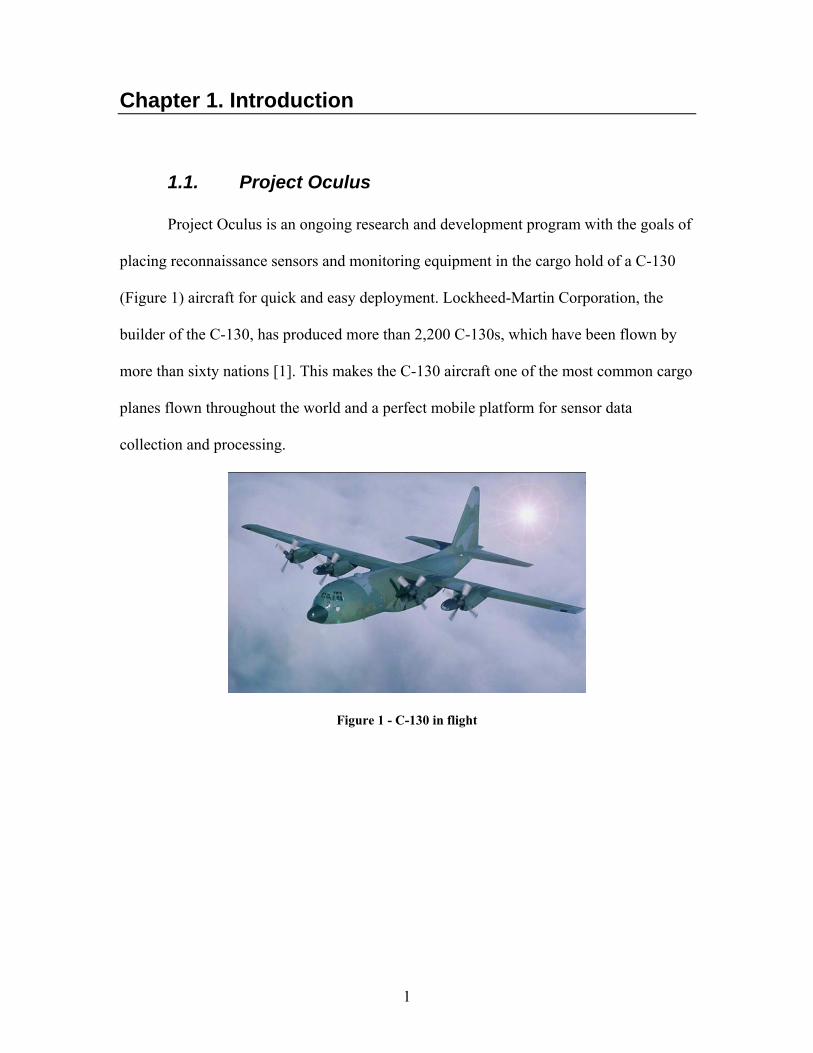
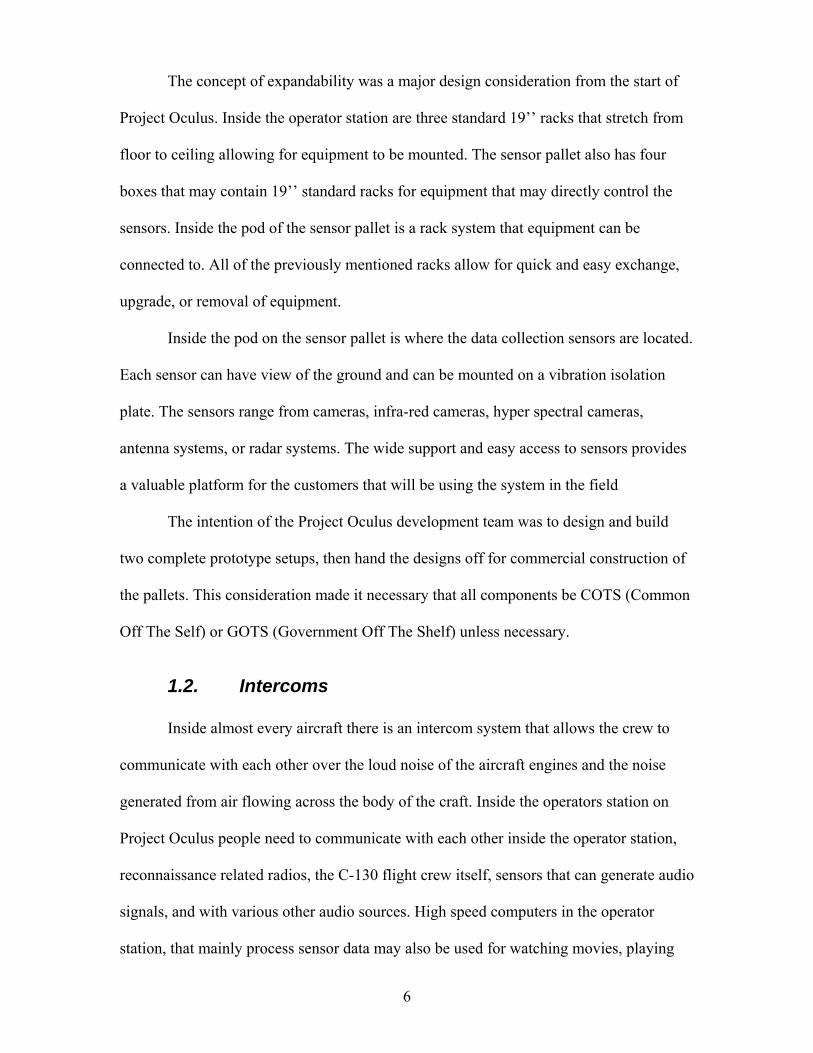
Project Oculus is an ongoing research and development program with the goals of
placing reconnaissance sensors and monitoring equipment in the cargo hold of a C-130
(Figure 1) aircraft for quick and easy deployment. Lockheed-Martin Corporation, the
builder of the C-130, has produced more than 2,200 C-130s, which have been flown by
more than sixty nations [1]. This makes the C-130 aircraft one of the most common cargo
planes flown throughout the world and a perfect mobile platform for sensor data
collection and processing.
Figure 1 - C-130 in flight
2
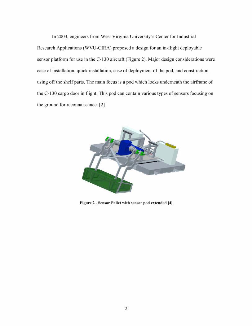
In 2003, engineers from West Virginia University’s Center for Industrial
Research Applications (WVU-CIRA) proposed a design for an in-flight deployable
sensor platform for use in the C-130 aircraft (Figure 2). Major design considerations were
ease of installation, quick installation, ease of deployment of the pod, and construction
using off the shelf parts. The main focus is a pod which locks underneath the airframe of
the C-130 cargo door in flight. This pod can contain various types of sensors focusing on
the ground for reconnaissance. [2]
Figure 2 - Sensor Pallet with sensor pod extended [4]
3
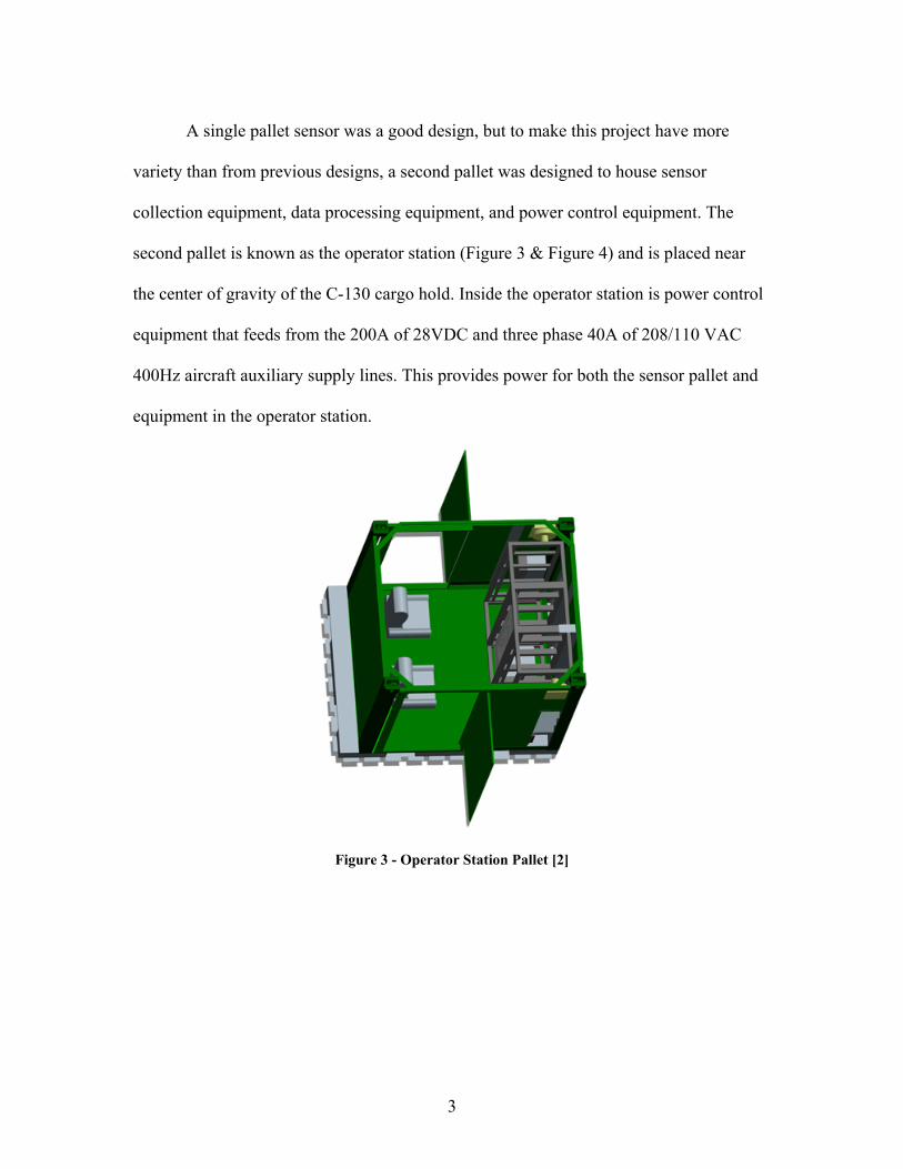
A single pallet sensor was a good design, but to make this project have more
variety than from previous designs, a second pallet was designed to house sensor
collection equipment, data processing equipment, and power control equipment. The
second pallet is known as the operator station (Figure 3 & Figure 4) and is placed near
the center of gravity of the C-130 cargo hold. Inside the operator station is power control
equipment that feeds from the 200A of 28VDC and three phase 40A of 208/110 VAC
400Hz aircraft auxiliary supply lines. This provides power for both the sensor pallet and
equipment in the operator station.
Figure 3 - Operator Station Pallet [2]
4
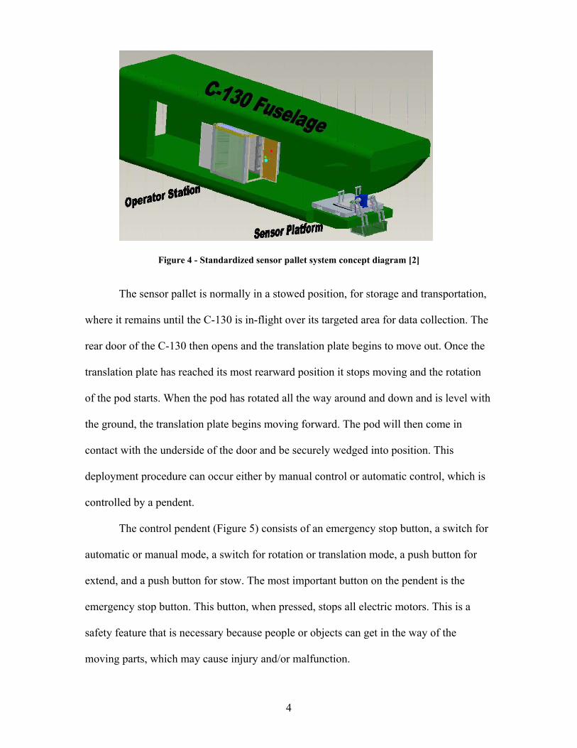
Figure 4 - Standardized sensor pallet system concept diagram [2]
The sensor pallet is normally in a stowed position, for storage and transportation,
where it remains until the C-130 is in-flight over its targeted area for data collection. The
rear door of the C-130 then opens and the translation plate begins to move out. Once the
translation plate has reached its most rearward position it stops moving and the rotation
of the pod starts. When the pod has rotated all the way around and down and is level with
the ground, the translation plate begins moving forward. The pod will then come in
contact with the underside of the door and be securely wedged into position. This
deployment procedure can occur either by manual control or automatic control, which is
controlled by a pendent.
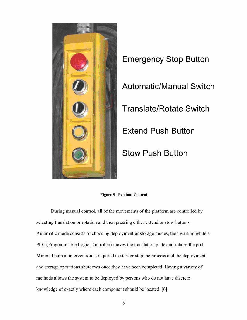
The control pendent (Figure 5) consists of an emergency stop button, a switch for
automatic or manual mode, a switch for rotation or translation mode, a push button for
extend, and a push button for stow. The most important button on the pendent is the
emergency stop button. This button, when pressed, stops all electric motors. This is a
safety feature that is necessary because people or objects can get in the way of the
moving parts, which may cause injury and/or malfunction.
5
Figure 5 - Pendant Control
During manual control, all of the movements of the platform are controlled by
selecting translation or rotation and then pressing either extend or stow buttons.
Automatic mode consists of choosing deployment or storage modes, then waiting while a
PLC (Programmable Logic Controller) moves the translation plate and rotates the pod.
Minimal human intervention is required to start or stop the process and the deployment
and storage operations shutdown once they have been completed. Having a variety of
methods allows the system to be deployed by persons who do not have discrete
knowledge of exactly where each component should be located. [6]
6
The concept of expandability was a major design consideration from the start of
Project Oculus. Inside the operator station are three standard 19’’ racks that stretch from
floor to ceiling allowing for equipment to be mounted. The sensor pallet also has four
boxes that may contain 19’’ standard racks for equipment that may directly control the
sensors. Inside the pod of the sensor pallet is a rack system that equipment can be
connected to. All of the previously mentioned racks allow for quick and easy exchange,
upgrade, or removal of equipment.
Inside the pod on the sensor pallet is where the data collection sensors are located.
Each sensor can have view of the ground and can be mounted on a vibration isolation
plate. The sensors range from cameras, infra-red cameras, hyper spectral cameras,
antenna systems, or radar systems. The wide support and easy access to sensors provides
a valuable platform for the customers that will be using the system in the field
The intention of the Project Oculus development team was to design and build
two complete prototype setups, then hand the designs off for commercial construction of
the pallets. This consideration made it necessary that all components be COTS (Common
Off The Self) or GOTS (Government Off The Shelf) unless necessary.
1.2. Intercoms
Inside almost every aircraft there is an intercom system that allows the crew to
communicate with each other over the loud noise of the aircraft engines and the noise
generated from air flowing across the body of the craft. Inside the operators station on
Project Oculus people need to communicate with each other inside the operator station,
reconnaissance related radios, the C-130 flight crew itself, sensors that can generate audio
signals, and with various other audio sources. High speed computers in the operator
station, that mainly process sensor data may also be used for watching movies, playing
7
video games, or listening to music during the time when the collection of sensor data is
not necessary such as world wide transport time to the scene of operations. These
activities are common among flight crews that have nothing to do while in transit to a
destination.
Adding to the complication of intercoms is the use of several different types of
headsets. Headset speakers can have different impedances and headset microphones can
be of completely different types with different impedances as well. This often leads to
incompatibilities often resulting in low volume levels. Most aviators and sensor operators
carry their own headset, which could be of any type, civilian or military, or they may
sometimes carry multiple types of headsets. Aviators usually prefer to use their own
personal headsets instead of ones provided by the aircraft. The most common reasons for
this are sanitation and comfort.
What is needed for Project Oculus is a design of an intercom system that can
allow the project operators to communicate with one another over the noise of the
aircraft, communicate with the C-130 intercom system, communicate with radios, be
expandable to allow for future upgrades, and allow the operators to use whichever
headsets they prefer. It was decided early because of different headset specifications that
it would be necessary for most types of headsets to be used in the intercom system.
8
Chapter 2. Statement of the Problem
A device does not exist off the shelf that meets the requirements of allowing both
commercial and military headsets to be used on an aircraft intercom system. Project
Oculus thus needed a method of allowing multiple headsets to be used with an intercom
design that allows for three positions in the operator station to communicate with one
another, with an external connection, and with a connection to the C-130 intercom
system.
It is proposed that an intercom system be developed, constructed, and tested that
can utilize military, civilian, and high quality active noise reduction headsets on the three
working positions of the operator station. In addition, this intercom system must interface
properly with the C-130 on-board internal communication intercom and with radios that
may be installed in the operator station for exclusive use by the system operators. The
load-master must in addition have a connection outside of the operator station that can
communicate directly with the operators independent of the C-130 on-board intercom
system when necessary.
9
Chapter 3. Aircraft Intercoms
Inside almost every aircraft is an intercom system. The system might be as simple
as a two person system which is also connected to a radio, or extremely complex with
many headsets being supported. In previous years, headsets were connected in series to a
single amplifier which had all the microphones as inputs. The system only worked well
when the correct numbers of headsets were connected, and with the constraint only one
person could talk at a time. Today, thanks to small components, near ideal low noise
amplifiers and digital circuits, intercom systems are much easier to construct and expand.
The market today provides a designer with a plethora of different intercom
systems to choose from. Although each manufacturer has unique and appealing attributes,
each also has downsides. The major downside to the majority of intercoms for this
project is that they are not expandable and accept only one type of headset. These types
of intercom systems are ideal for the larger numbers of small aircraft that need only the
minimum number of users. Fortunately for this project, Northern Airborne Technology
provides intercoms that can be connected together with their Tie Line technology, which
can expand the intercom system.
10
3.1. Different Types of Intercoms
Intercom systems in a aircraft are different depending upon who makes the
aircraft, when it was made, and what sector it will server. Manufacturers such as Boeing,
Lockheed-Martin, Mcdonnell-Douglas, Gulfstream, Cessna, and others all have different
intercom equipment for different purposes. The cargo planes the military flies, like the C-
130, do not have very much noise insulation, which makes the interior background noise
deafening. Headsets that cover the ear must be able to overcome that noise. Commerical
aircraft such as the Gulfstream G500 has noise insulation and is very quiet on the interior;
therefore an intercom system is mainly used as an interface to radios and the cabin
loudspeaker.
Specifications and special features of intercom systems vary depending upon the
application and buyer of the aircraft. The specifications include what type of headset is
meant for the intercom, how many headsets can be connected to the intercom, and what
connections to radios or music sources are required.
Typically when an intercom user wishes to transmit from their microphone they
must first press a “push to talk” button. The alternative to this is using VOX (voice
Activation) which is the most useful and sometimes the most annoying feature. This
allows a user to activate their microphone by speaking. A level of activation is usually set
by a knob, so when the microphone level goes over the activation threshold, the intercom
starts transmitting from the microphone. This allows a headset to be hands free, i.e. no
pushing a button to talk. The main problem is that loud background noise can start the
transmission, the level is set too high and the user has problems starting the transmission,
or a time delay to activation is so long that the first syllabus or word of whatever the user
says is cutoff.
11
3.1.1. Military Intercoms
The military usually outfits cargo planes with simple intercom systems that lack
voice activation and music inputs. The majority of these intercom systems were designed
in the 1960’s when vacuum tubes were the only solution, and the constructed intercoms
still exist on aircraft today.
The C-130 aircraft has a military specification intercom control box type
AN/AIC-18 [7]. This box accepts military headsets of 150 ohm speaker impedance and is
monorail. The microphone input to this box is required to be a dynamic microphone.
Inside the cockpit of the C-130 are military headset connections for the pilot, co-pilot,
navigator, and others. These headsets all communicate together or each connection can
communicate with a radio. Also there are several connections in the cargo hold of the C-
130 that can communicate with the cockpit. Included also in the cargo hold are numerous
other intercom connections that allow many headsets to communicate with other headsets
that are in the cargo hold.
3.1.2. Civilian Intercoms
Civilian intercom systems started with the same headset specifications that
military systems had. Because civilian intercom systems are not hindered by military
standards, the intercoms evolved more quickly. Most notable of the additional features
for civilian intercoms are the ability to mix in music to the intercom and have voice
activation. These features and others give reason for choosing civilian intercoms when
implementing a new intercom system.
3.2. Headsets and their impedances
12
The world of aircraft intercom headsets has evolved resulting in split standards
throughout the years [5]. The end result is a standard for most commercial aircraft and a
standard for all military aircraft.
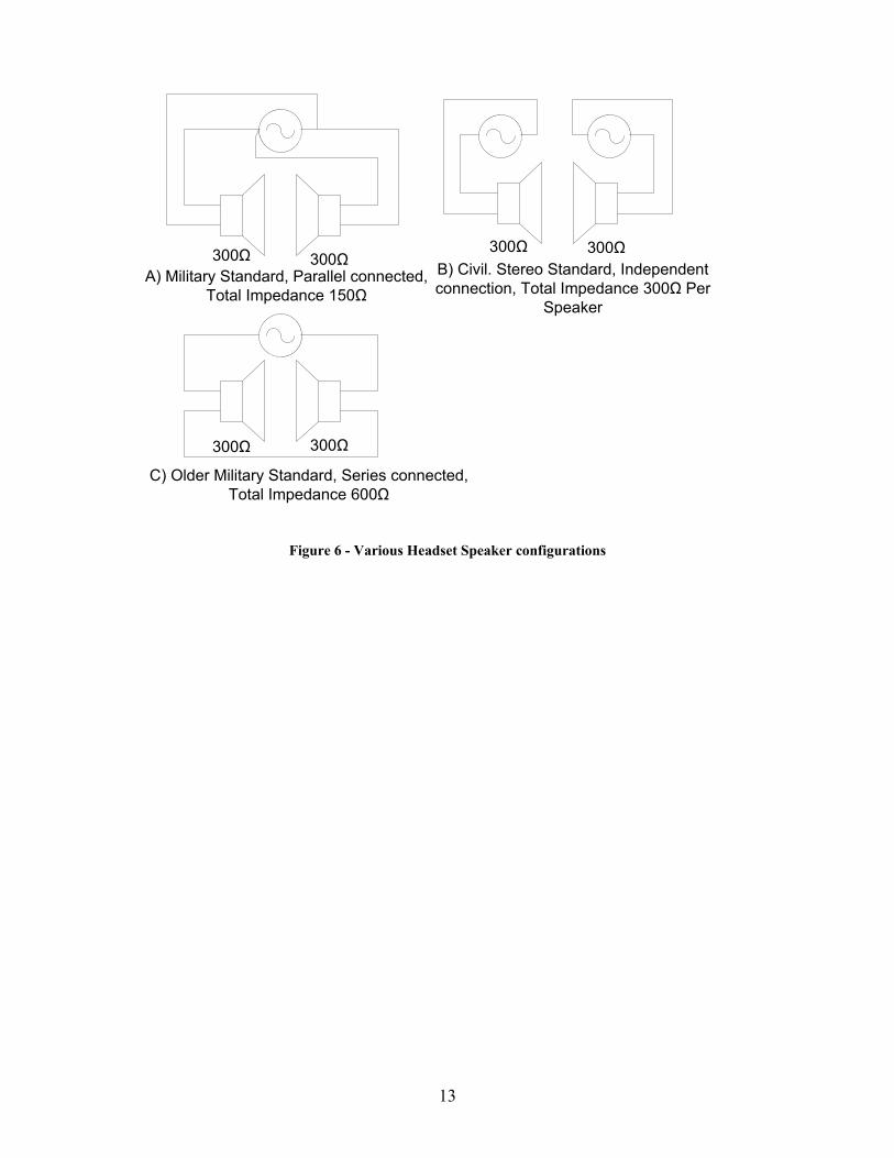
Both the military and commercial speakers in headsets started out as 300 Ohm
speakers connected in series (Figure 6 C). This created a total impedance of 600 Ohm for
a single headset. Speakers can, over time, either short circuit creating a 300 Ohm speaker
in one ear that will be half as loud or break to open circuit, which renders the headset
useless (both speakers output no sound).
The military solution (Figure 6 A) was to connect the speakers in parallel so that
if the coils in the speaker broke to open circuit, there would not be a total malfunction.
Since, the majority of the time, the coils break to open circuit instead of shorting this
created a fail-safe system for headset speakers. Now, military headsets are a 150 Ohm
headset (total of the two 300 Ohm speakers connected in parallel) that is mono (both
speakers output the same signal).
Civilian aircraft headsets took a different route (Figure 6 B) by splitting the two
speakers for stereo (each speaker has a separate signal), which kept the impedance of
each speaker at 300 Ohms. This gave civilian pilots the ability to listen to music in stereo
and not be concerned with a total failure if one speaker should fail. For specifications on
headsets see Appendix B.
13
300Ω 300Ω
300Ω 300Ω
300Ω 300Ω
C) Older Military Standard, Series connected, Total Impedance 600Ω
A) Military Standard, Parallel connected, Total Impedance 150Ω
B) Civil. Stereo Standard, Independent connection, Total Impedance 300Ω Per
Speaker
Figure 6 - Various Headset Speaker configurations
14
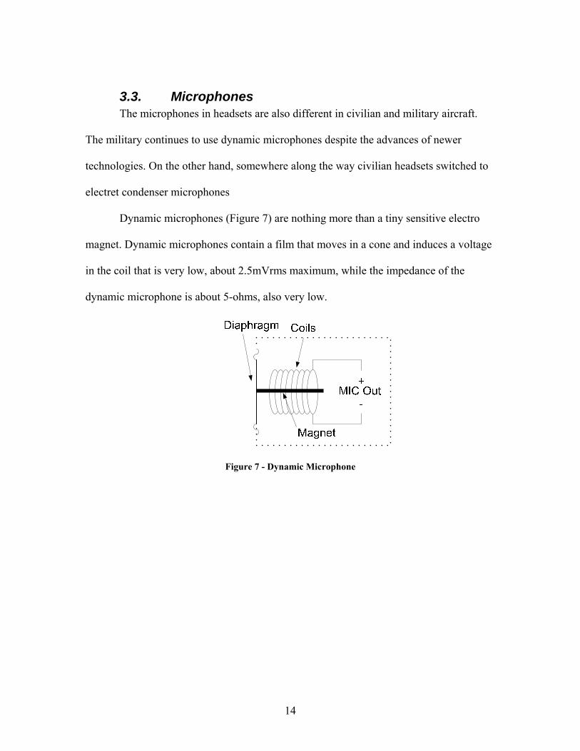
3.3. Microphones The microphones in headsets are also different in civilian and military aircraft.
The military continues to use dynamic microphones despite the advances of newer
technologies. On the other hand, somewhere along the way civilian headsets switched to
electret condenser microphones
Dynamic microphones (Figure 7) are nothing more than a tiny sensitive electro
magnet. Dynamic microphones contain a film that moves in a cone and induces a voltage
in the coil that is very low, about 2.5mVrms maximum, while the impedance of the
dynamic microphone is about 5-ohms, also very low.
Figure 7 - Dynamic Microphone
15
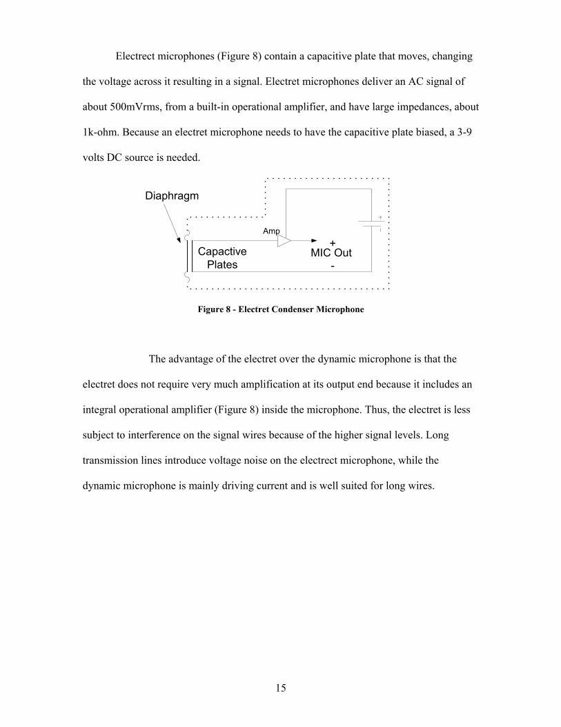
Electrect microphones (Figure 8) contain a capacitive plate that moves, changing
the voltage across it resulting in a signal. Electret microphones deliver an AC signal of
about 500mVrms, from a built-in operational amplifier, and have large impedances, about
1k-ohm. Because an electret microphone needs to have the capacitive plate biased, a 3-9
volts DC source is needed.
MIC Out+
-Capactive
Plates
Diaphragm
Amp
Figure 8 - Electret Condenser Microphone
The advantage of the electret over the dynamic microphone is that the
electret does not require very much amplification at its output end because it includes an
integral operational amplifier (Figure 8) inside the microphone. Thus, the electret is less
subject to interference on the signal wires because of the higher signal levels. Long
transmission lines introduce voltage noise on the electrect microphone, while the
dynamic microphone is mainly driving current and is well suited for long wires.
16
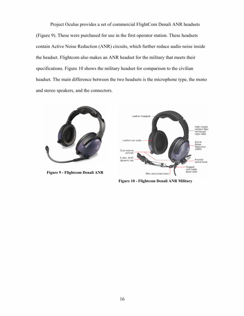
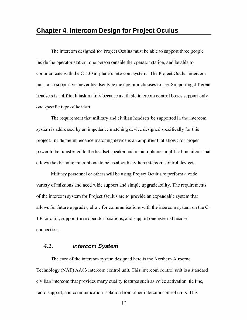
Project Oculus provides a set of commercial FlightCom Denali ANR headsets
(Figure 9). These were purchased for use in the first operator station. These headsets
contain Active Noise Reduction (ANR) circuits, which further reduce audio noise inside
the headset. Flightcom also makes an ANR headset for the military that meets their
specifications. Figure 10 shows the military headset for comparison to the civilian
headset. The main difference between the two headsets is the microphone type, the mono
and stereo speakers, and the connectors.
Figure 9 - Flightcom Denali ANR
Figure 10 - Flightcom Denali ANR Military
17
Chapter 4. Intercom Design for Project Oculus
The intercom designed for Project Oculus must be able to support three people
inside the operator station, one person outside the operator station, and be able to
communicate with the C-130 airplane’s intercom system. The Project Oculus intercom
must also support whatever headset type the operator chooses to use. Supporting different
headsets is a difficult task mainly because available intercom control boxes support only
one specific type of headset.
The requirement that military and civilian headsets be supported in the intercom
system is addressed by an impedance matching device designed specifically for this
project. Inside the impedance matching device is an amplifier that allows for proper
power to be transferred to the headset speaker and a microphone amplification circuit that
allows the dynamic microphone to be used with civilian intercom control devices.
Military personnel or others will be using Project Oculus to perform a wide
variety of missions and need wide support and simple upgradeability. The requirements
of the intercom system for Project Oculus are to provide an expandable system that
allows for future upgrades, allow for communications with the intercom system on the C-
130 aircraft, support three operator positions, and support one external headset
connection.
4.1. Intercom System
The core of the intercom system designed here is the Northern Airborne
Technology (NAT) AA83 intercom control unit. This intercom control unit is a standard
civilian intercom that provides many quality features such as voice activation, tie line,
radio support, and communication isolation from other intercom control units. This
18
device connects to the headsets, music inputs, and the tie line. Component devices such
as the NAT digital crossover device (AA36-100), allow the NAT AA83 to have proper
signals that can transmit and receive audio to the C-130 intercom system.
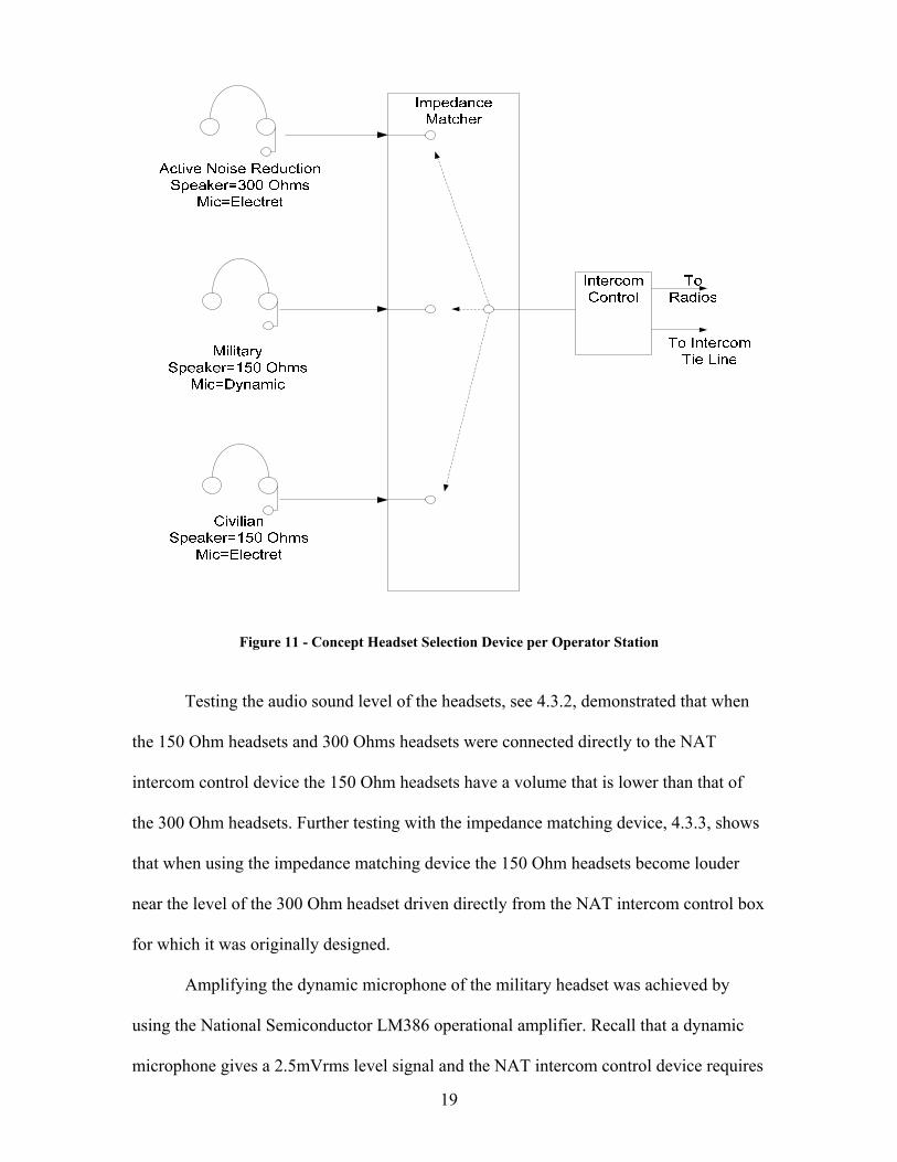
The concept of a device to support headsets that contain speakers with different
impedances and different types of microphones is shown in Figure 11. This device should
pass the speaker signals from the intercom control box to the headset making sure that the
entire signal in its original form arrives at the speaker. This means that if the impedance
of the headset does not match what the intercom control requires it will have to change
the impedance. Also, the device should convert the microphone signal level to that of the
proper signal level for the intercom control box.
19
Figure 11 - Concept Headset Selection Device per Operator Station
Testing the audio sound level of the headsets, see 4.3.2, demonstrated that when
the 150 Ohm headsets and 300 Ohms headsets were connected directly to the NAT
intercom control device the 150 Ohm headsets have a volume that is lower than that of
the 300 Ohm headsets. Further testing with the impedance matching device, 4.3.3, shows
that when using the impedance matching device the 150 Ohm headsets become louder
near the level of the 300 Ohm headset driven directly from the NAT intercom control box
for which it was originally designed.
Amplifying the dynamic microphone of the military headset was achieved by
using the National Semiconductor LM386 operational amplifier. Recall that a dynamic
microphone gives a 2.5mVrms level signal and the NAT intercom control device requires

20
500mVrms levels. The LM386 amplifier device has a built in ability to provide the
necessary amplification internally with minimal external parts. Testing of this device, see
4.3.5, shows that proper signal levels were reached.
21
4.2. Intercom Design
The custom built impedance matching device will allow the use of different
headset types that are not compatible with the AA83 intercom control device. This allows
aviators that carry their own headsets with them to use what they feel most comfortable
with. The importance of the device to pass voice frequencies to the headsets was a major
design goal.
The impedance matching device consists of three amplifier circuits. The first
amplifier has a voltage gain of 200, and is used for the amplification of the dynamic
microphone signal as described previously. The other two amplifiers are used to buffer
the signal to the headsets that are not impedance matched for the AA83 intercom control
device. For more information on the design and construction of this device see Appendix
A.
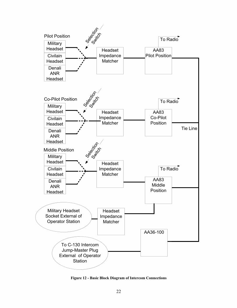
The intercom designed for Project Oculus provides for three different types of
headset connections for each operator position inside the operator station, an external
connection for a person operating outside the operator station, and another external cable
connection to provide communications with the C-130 intercom system. A basic
connection diagram is shown by Figure 12 below. The details and schematics are
discussed in Appendix B.
22
Tie Line
AA83Pilot Position
AA83Middle
Position
Headset Impedance
Matcher
Headset Impedance
Matcher
Headset Impedance
Matcher
AA83Co-Pilot Position
Headset Impedance
Matcher
To Radio
To Radio
To Radio
Military Headset Socket External of Operator Station
To C-130 IntercomJump-Master Plug
External of Operator Station
Military HeadsetCivilain HeadsetDenali ANR
Headset
Military HeadsetCivilain HeadsetDenali ANR
Headset
Military HeadsetCivilain HeadsetDenali ANR
Headset
Selec
tion
Switc
h
Selec
tion
Switc
h
Selec
tion
Switc
h
AA36-100
Pilot Position
Middle Position
Co-Pilot Position
Figure 12 - Basic Block Diagram of Intercom Connections
23
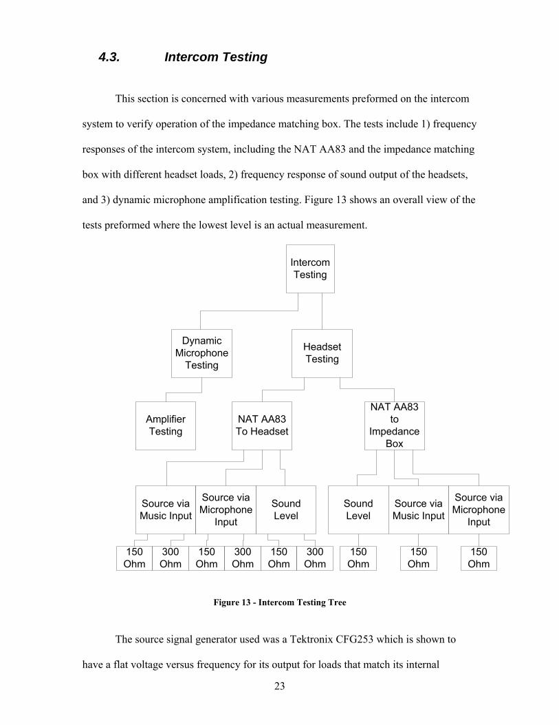
4.3. Intercom Testing
This section is concerned with various measurements preformed on the intercom
system to verify operation of the impedance matching box. The tests include 1) frequency
responses of the intercom system, including the NAT AA83 and the impedance matching
box with different headset loads, 2) frequency response of sound output of the headsets,
and 3) dynamic microphone amplification testing. Figure 13 shows an overall view of the
tests preformed where the lowest level is an actual measurement.
Intercom Testing
Headset Testing
Dynamic Microphone
Testing
NAT AA83 To Headset
NAT AA83 to
Impedance Box
Sound Level
150 Ohm
300 Ohm
Source via Music Input
Source via Microphone
Input
150 Ohm
300 Ohm
150 Ohm
300 Ohm
150 Ohm
Sound Level
Source via Music Input
Source via Microphone
Input
150 Ohm
150 Ohm
Amplifier Testing
Figure 13 - Intercom Testing Tree
The source signal generator used was a Tektronix CFG253 which is shown to
have a flat voltage versus frequency for its output for loads that match its internal

24
impedance. The output impedance of the signal generator is specified at 50 Ohms. The
oscilloscope probe used in the tests, Tektronix TDS3052B oscilloscope, is a high
impedance voltage probe. All of the tests involving the AA83 were conducted with the
volume control knob set at half the full level unless otherwise stated.
4.3.1. Methods of Calculation
The majority of the graphs show levels of either voltage gain in dB, dBm or
dBuV. A dB, or Decibel, is a logarithmic scale that allows humans to deal with large
dynamic range numbers instead of extremely large or extremely small numbers. A
decibel refers to a relative change, such as a voltage gain (voltage out divided by voltage
in). This can also assume “voltage in” to be a standard of one volt (dBV), or one micro-
volt (dBμV).
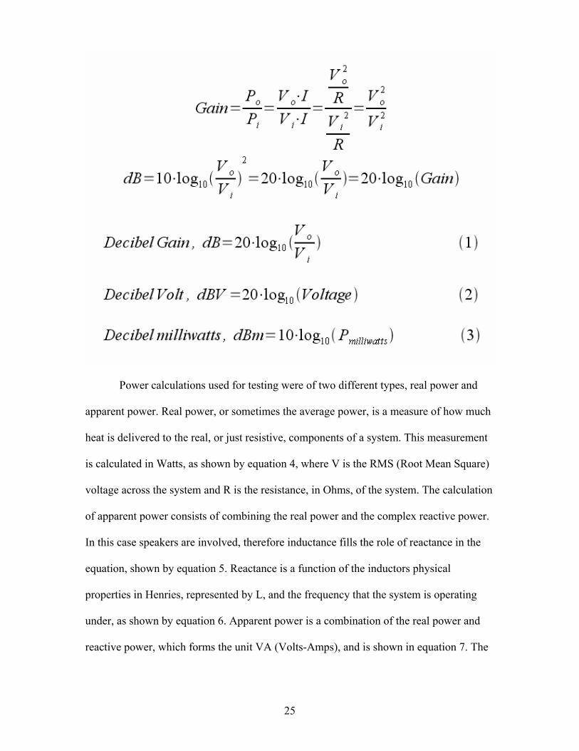
Voltage gain in terms of dB (i.e. referenced to one volt) is shown in equation (1).
Another type of decibel calculation is the dBV (decibel volt), which is nothing more than
a decibel with reference to one volt, as shown in equation (2). The calculation of power in
dBm, or dB milliwatts, is determined by ten times the log of the power in milliwatts, as
shown in equation (3) with an input power of 1mW.
25
Power calculations used for testing were of two different types, real power and
apparent power. Real power, or sometimes the average power, is a measure of how much
heat is delivered to the real, or just resistive, components of a system. This measurement
is calculated in Watts, as shown by equation 4, where V is the RMS (Root Mean Square)
voltage across the system and R is the resistance, in Ohms, of the system. The calculation
of apparent power consists of combining the real power and the complex reactive power.
In this case speakers are involved, therefore inductance fills the role of reactance in the
equation, shown by equation 5. Reactance is a function of the inductors physical
properties in Henries, represented by L, and the frequency that the system is operating
under, as shown by equation 6. Apparent power is a combination of the real power and
reactive power, which forms the unit VA (Volts-Amps), and is shown in equation 7. The
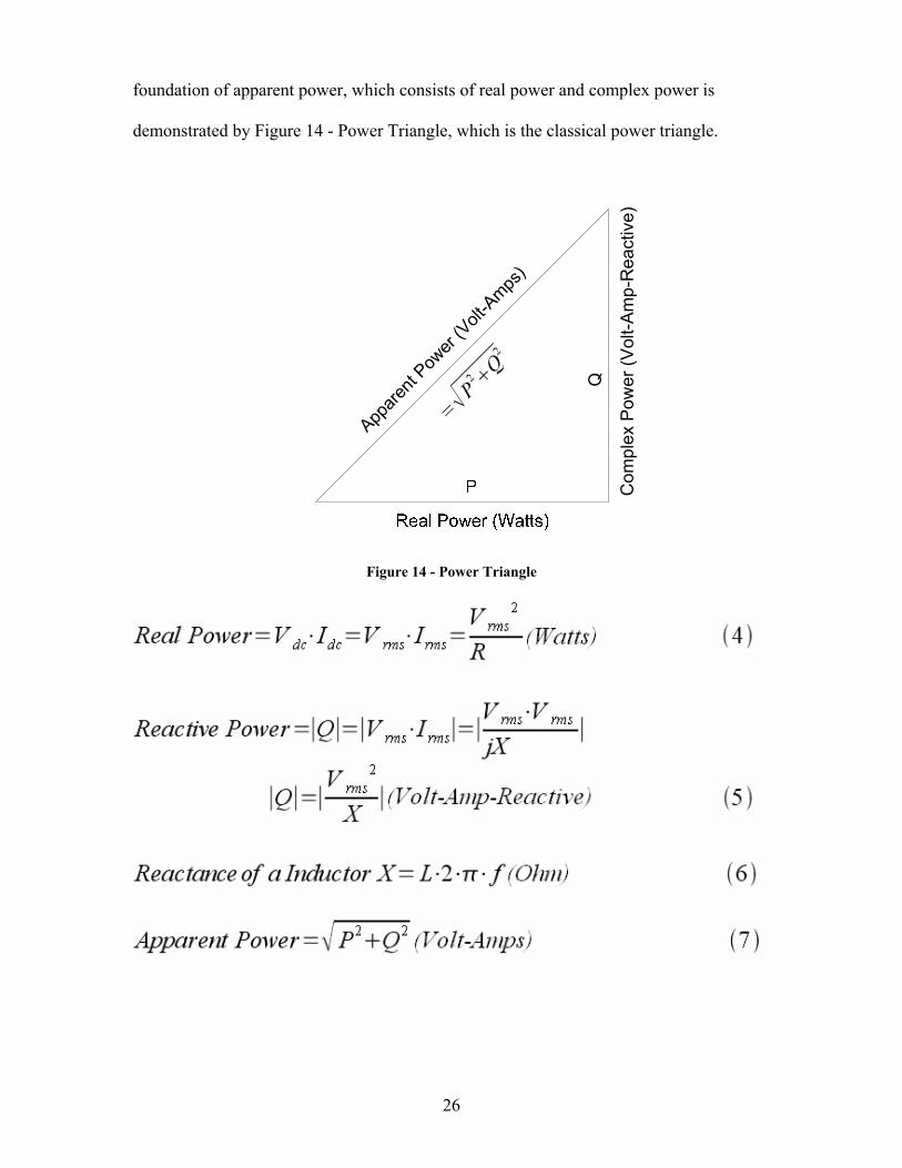
26
foundation of apparent power, which consists of real power and complex power is
demonstrated by Figure 14 - Power Triangle, which is the classical power triangle.
App
arent
Power
(Volt
-Amps
)
Com
plex
Pow
er (V
olt-A
mp-
Rea
ctiv
e)
Q
Figure 14 - Power Triangle
27
4.3.2. Headset tests
The voltage gain versus frequency tests, 20Hz to 20 kHz, of the headset are
broken down into several categories. First, testing of the NAT AA83 intercom device
with the 150 and 300 ohm headsets connected directly to the proper device outputs. The
NAT AA83 has three connections for inputs, microphone, music, and the tie line. All
three or one of the inputs can be used simultaneously, but for the following tests only the
microphone input or the music input was used. Second, measurements were taken with
the impedance matching device driving the 150 Ohm headset to determine how well it
performs. Third, a sound dB meter, type RadioShack 33-2055, was used to measure the
sound ouput in terms of sound pressure level (SPL) of the headsets.
The Military specification headset, which generally has a speaker impedance of
150 Ohms, was used as the 150 Ohm test headset. The mono civilian and military
headsets have the same speaker specification, so only one type of these is required. The
Flightcom Denali ANR headsets are 300 Ohm stereo speakers. Both speakers of the
Denali headset were connected in stereo mode. Only the left channel was used for voltage
measurements, except during the sound level tests where stereo mode was utilized.
4.3.2.1. AA83 Frequency Response Using the Microphone Input
This testing section is devoted to testing different headset impedances while using
the microphone input of the NAT AA83. The AA83 has an input that is specifically
designed for electret microphone signal level, know as the microphone input. This
connection, one of many, was used as an input to the system for these tests. The signal
generator impedance (50 Ohm) did not meet the impedance specifications that the AA83
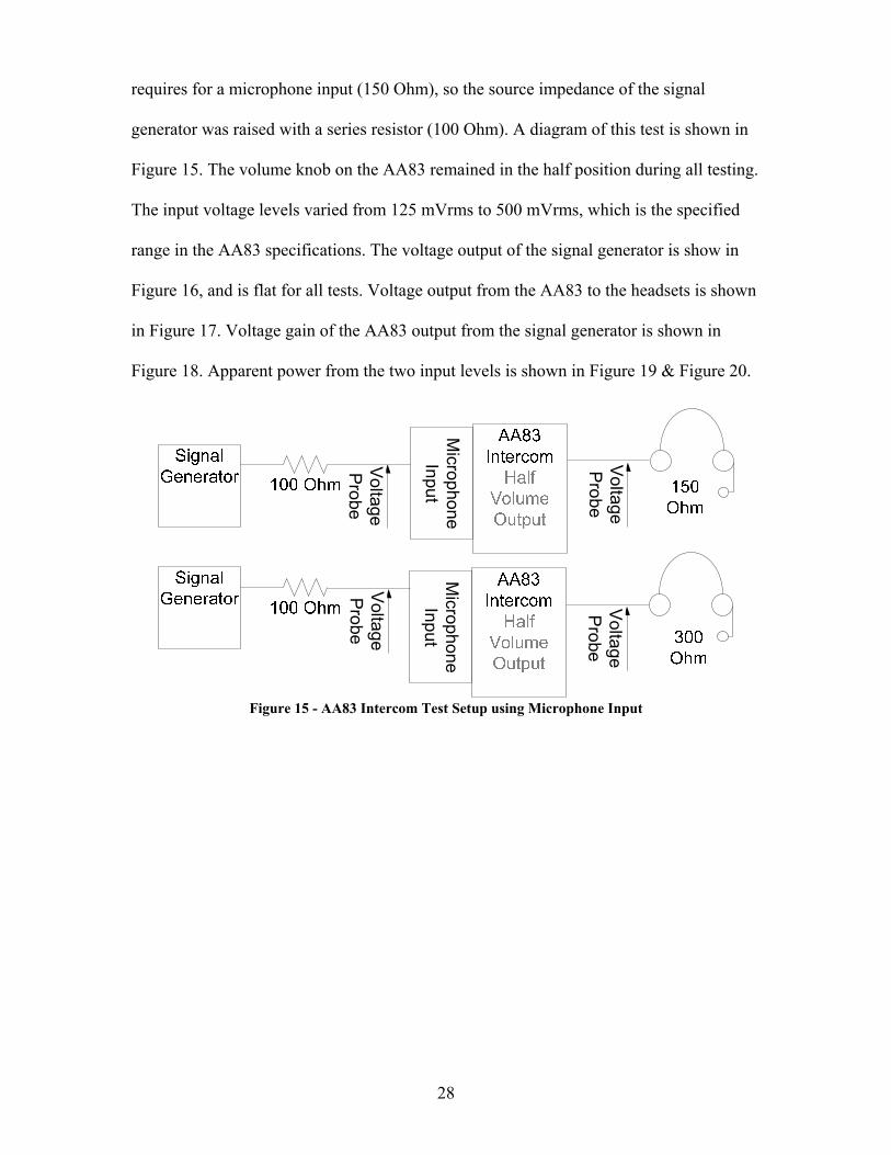
28
requires for a microphone input (150 Ohm), so the source impedance of the signal
generator was raised with a series resistor (100 Ohm). A diagram of this test is shown in
Figure 15. The volume knob on the AA83 remained in the half position during all testing.
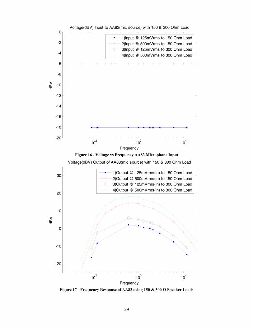
The input voltage levels varied from 125 mVrms to 500 mVrms, which is the specified
range in the AA83 specifications. The voltage output of the signal generator is show in
Figure 16, and is flat for all tests. Voltage output from the AA83 to the headsets is shown
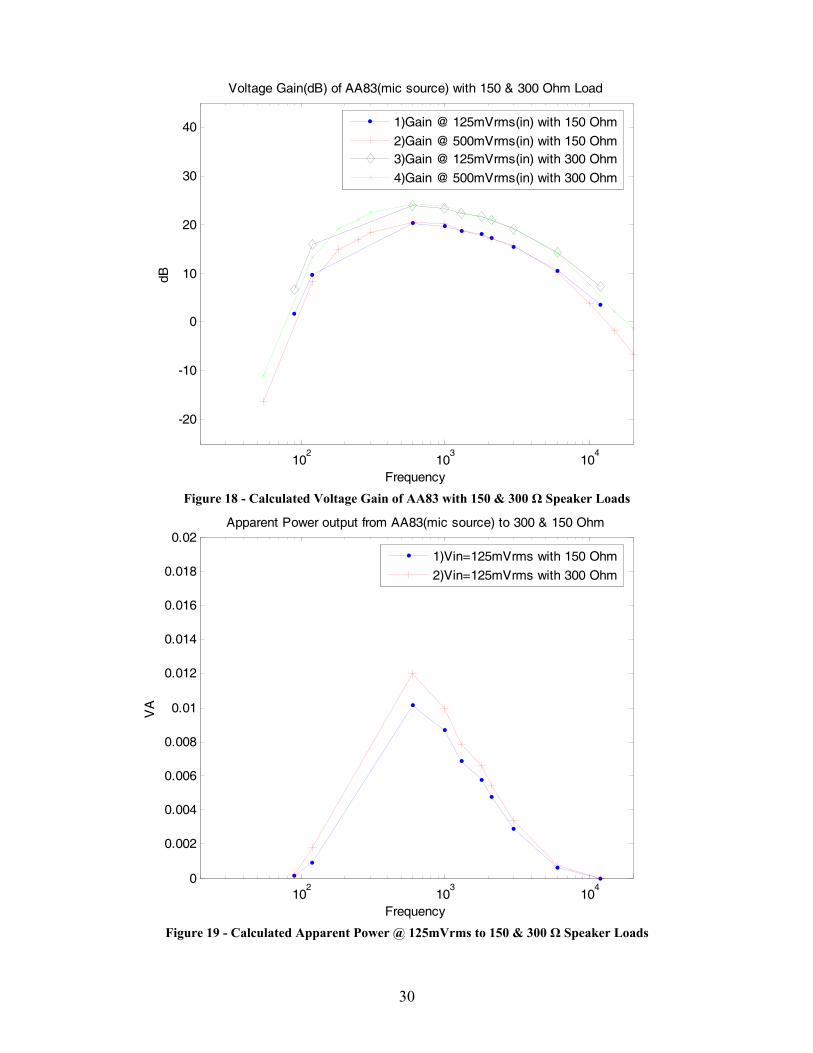
in Figure 17. Voltage gain of the AA83 output from the signal generator is shown in
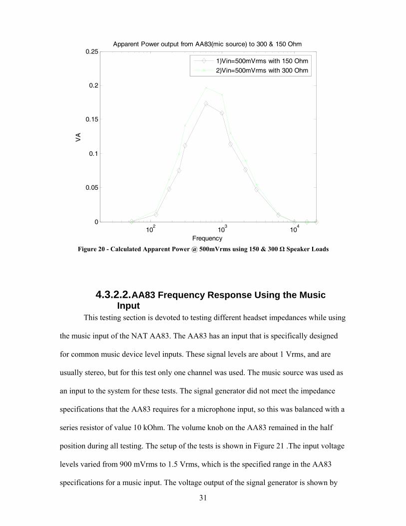
Figure 18. Apparent power from the two input levels is shown in Figure 19 & Figure 20.
Voltage
Probe
Voltage
Probe
Voltage
Probe
Microphone
Input
Voltage
Probe
Microphone
Input
Figure 15 - AA83 Intercom Test Setup using Microphone Input
29
102
103
104
-20
-18
-16
-14
-12
-10
-8
-6
-4
-2
0Voltage(dBV) Input to AA83(mic source) with 150 & 300 Ohm Load
Frequency
dBV
1)Input @ 125mVrms to 150 Ohm Load
2)Input @ 500mVrms to 150 Ohm Load3)Input @ 125mVrms to 300 Ohm Load
4)Input @ 500mVrms to 300 Ohm Load
Figure 16 - Voltage vs Frequency AA83 Microphone Input
102
103
104
-20
-10
0
10
20
30
Voltage(dBV) Output of AA83(mic source) with 150 & 300 Ohm Load
Frequency
dBV
1)Output @ 125mVrms(in) to 150 Ohm Load
2)Output @ 500mVrms(in) to 150 Ohm Load3)Output @ 125mVrms(in) to 300 Ohm Load
4)Output @ 500mVrms(in) to 300 Ohm Load
Figure 17 - Frequency Response of AA83 using 150 & 300 Ω Speaker Loads
30
102
103
104
-20
-10
0
10
20
30
40
Voltage Gain(dB) of AA83(mic source) with 150 & 300 Ohm Load
Frequency
dB
1)Gain @ 125mVrms(in) with 150 Ohm
2)Gain @ 500mVrms(in) with 150 Ohm3)Gain @ 125mVrms(in) with 300 Ohm
4)Gain @ 500mVrms(in) with 300 Ohm
Figure 18 - Calculated Voltage Gain of AA83 with 150 & 300 Ω Speaker Loads
102
103
104
0
0.002
0.004
0.006
0.008
0.01
0.012
0.014
0.016
0.018
0.02Apparent Power output from AA83(mic source) to 300 & 150 Ohm
Frequency
VA
1)Vin=125mVrms with 150 Ohm
2)Vin=125mVrms with 300 Ohm
Figure 19 - Calculated Apparent Power @ 125mVrms to 150 & 300 Ω Speaker Loads
31
102
103
104
0
0.05
0.1
0.15
0.2
0.25Apparent Power output from AA83(mic source) to 300 & 150 Ohm
Frequency
VA
1)Vin=500mVrms with 150 Ohm
2)Vin=500mVrms with 300 Ohm
Figure 20 - Calculated Apparent Power @ 500mVrms using 150 & 300 Ω Speaker Loads
4.3.2.2. AA83 Frequency Response Using the Music Input
This testing section is devoted to testing different headset impedances while using
the music input of the NAT AA83. The AA83 has an input that is specifically designed
for common music device level inputs. These signal levels are about 1 Vrms, and are
usually stereo, but for this test only one channel was used. The music source was used as
an input to the system for these tests. The signal generator did not meet the impedance
specifications that the AA83 requires for a microphone input, so this was balanced with a
series resistor of value 10 kOhm. The volume knob on the AA83 remained in the half
position during all testing. The setup of the tests is shown in Figure 21 .The input voltage
levels varied from 900 mVrms to 1.5 Vrms, which is the specified range in the AA83
specifications for a music input. The voltage output of the signal generator is shown by
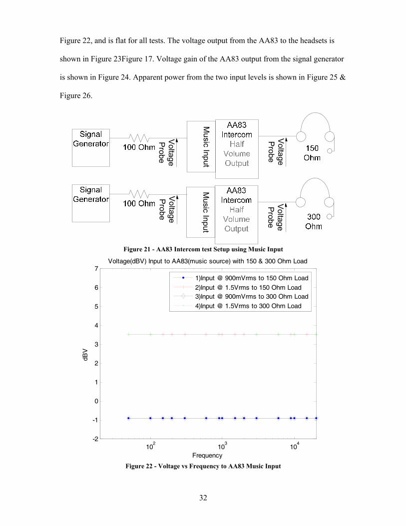
32
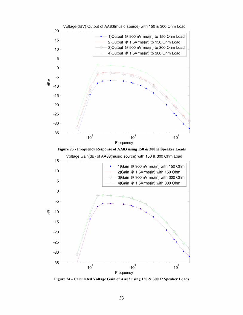
Figure 22, and is flat for all tests. The voltage output from the AA83 to the headsets is
shown in Figure 23Figure 17. Voltage gain of the AA83 output from the signal generator
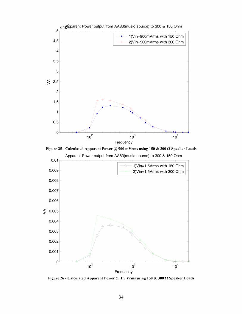
is shown in Figure 24. Apparent power from the two input levels is shown in Figure 25 &
Figure 26.
Voltage
Probe
Voltage
Probe
Voltage
Probe
Music Input
Voltage
Probe
Music Input
Figure 21 - AA83 Intercom test Setup using Music Input
102
103
104
-2
-1
0
1
2
3
4
5
6
7Voltage(dBV) Input to AA83(music source) with 150 & 300 Ohm Load
Frequency
dBV
1)Input @ 900mVrms to 150 Ohm Load
2)Input @ 1.5Vrms to 150 Ohm Load3)Input @ 900mVrms to 300 Ohm Load
4)Input @ 1.5Vrms to 300 Ohm Load
Figure 22 - Voltage vs Frequency to AA83 Music Input
33
102
103
104
-35
-30
-25
-20
-15
-10
-5
0
5
10
15
20Voltage(dBV) Output of AA83(music source) with 150 & 300 Ohm Load
Frequency
dBV
1)Output @ 900mVrms(in) to 150 Ohm Load
2)Output @ 1.5Vrms(in) to 150 Ohm Load3)Output @ 900mVrms(in) to 300 Ohm Load
4)Output @ 1.5Vrms(in) to 300 Ohm Load
Figure 23 - Frequency Response of AA83 using 150 & 300 Ω Speaker Loads
102
103
104
-35
-30
-25
-20
-15
-10
-5
0
5
10
15Voltage Gain(dB) of AA83(music source) with 150 & 300 Ohm Load
Frequency
dB
1)Gain @ 900mVrms(in) with 150 Ohm
2)Gain @ 1.5Vrms(in) with 150 Ohm3)Gain @ 900mVrms(in) with 300 Ohm
4)Gain @ 1.5Vrms(in) with 300 Ohm
Figure 24 - Calculated Voltage Gain of AA83 using 150 & 300 Ω Speaker Loads
34
102
103
104
0
0.5
1
1.5
2
2.5
3
3.5
4
4.5
5x 10
-3Apparent Power output from AA83(music source) to 300 & 150 Ohm
Frequency
VA
1)Vin=900mVrms with 150 Ohm
2)Vin=900mVrms with 300 Ohm
Figure 25 - Calculated Apparent Power @ 900 mVrms using 150 & 300 Ω Speaker Loads
102
103
104
0
0.001
0.002
0.003
0.004
0.005
0.006
0.007
0.008
0.009
0.01Apparent Power output from AA83(music source) to 300 & 150 Ohm
Frequency
VA
1)Vin=1.5Vrms with 150 Ohm
2)Vin=1.5Vrms with 300 Ohm
Figure 26 - Calculated Apparent Power @ 1.5 Vrms using 150 & 300 Ω Speaker Loads
35
4.3.2.3. Directly Driving Headsets from AA83 Conclusion
The previous tests show two major properties of the NAT AA83. First, the inputs
for both the microphone and music have a bandpass filter that is centered around the
human voice range (300 Hz-3kHz). Figure 23 demonstrates that the highest levels
coming out of the AA83 occur around the human voice range. Second, the 150 Ohm
headset does not receive as much power as the 300 Ohm headset, which is to be expected
because the AA83 is designed for a 300 Ohm load.
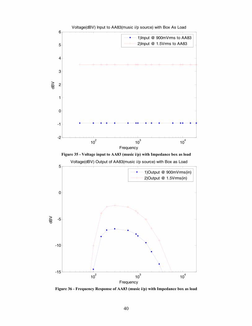
4.3.3. Impedance Matching Circuitry Tests Testing the impedance box involved three tests. First, the impedance matching
box was connected to the AA83, while the mic input was connected to the signal
generator, as shown by Figure 27, and various measurements were taken. Second, the
impedance matching box was connected to the AA83 while using the music input, shown
by Figure 34, and various measurements were taken. Third the impedance box was
subjected to different voltage level frequency sweeps to determine the response of the
impedance box by itself.
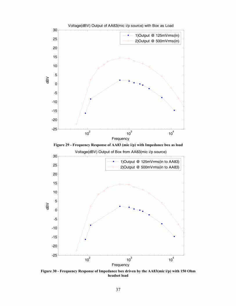
The input voltage to the AA83 using the microphone input is shown in Figure 28
and the music input is shown in Figure 35. Voltage output from the AA83 and input to
the impedance box with the microphone input can be shown by Figure 29 and music
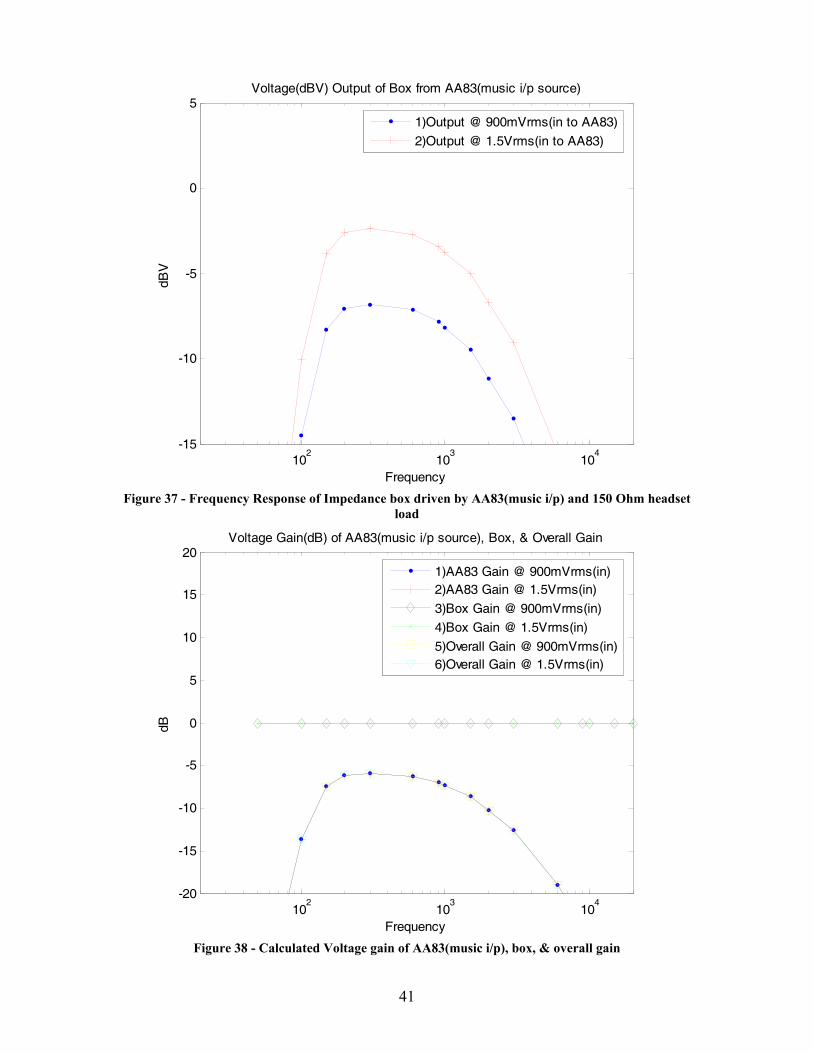
input by Figure 36. Voltage output from the impedance box with the 150 Ohm headset
load using the AA83 microphone input is shown by Figure 30 and the music input is
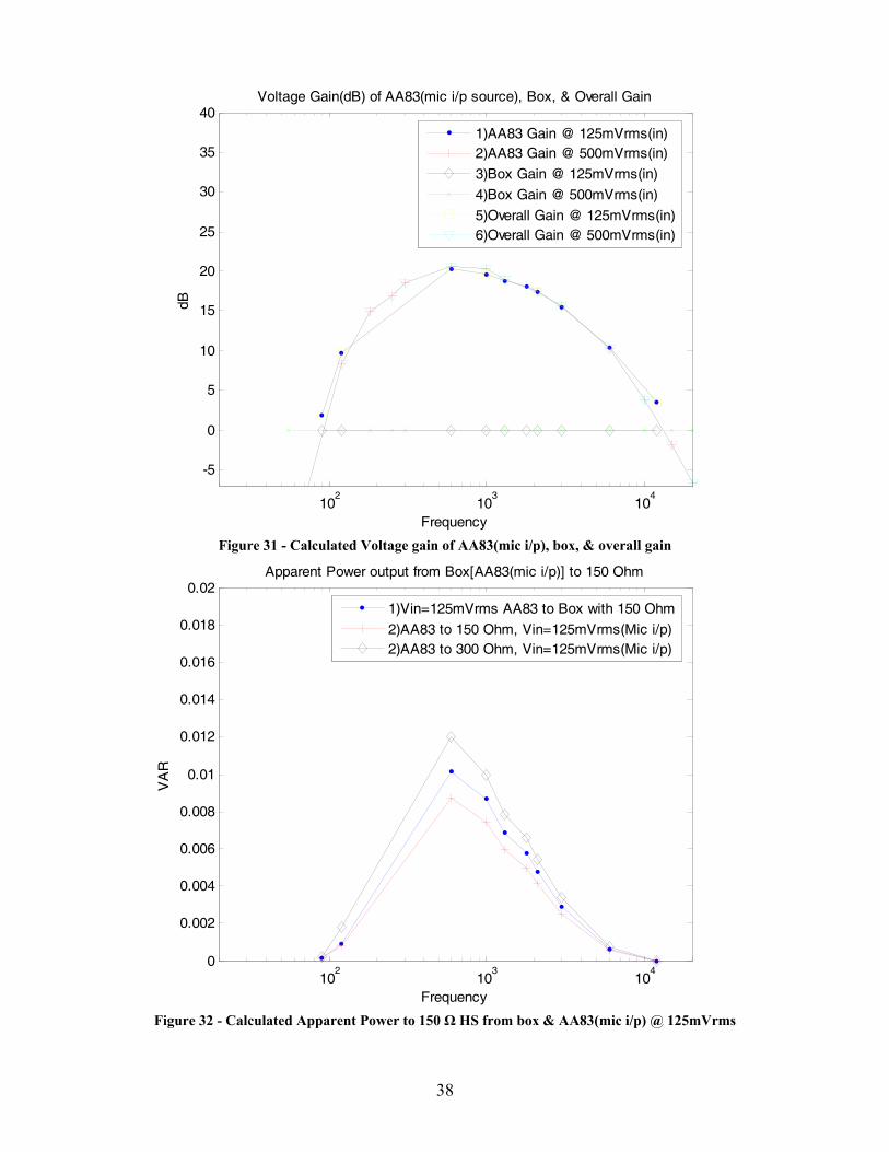
shown by Figure 37. Voltage gain of the AA83, impedance box, and overall through the
AA83 and impedance box with the AA83 microphone input is shown by Figure 31 and
the music input is shown by Figure 38. Apparent power from the 150 Ohm headset when
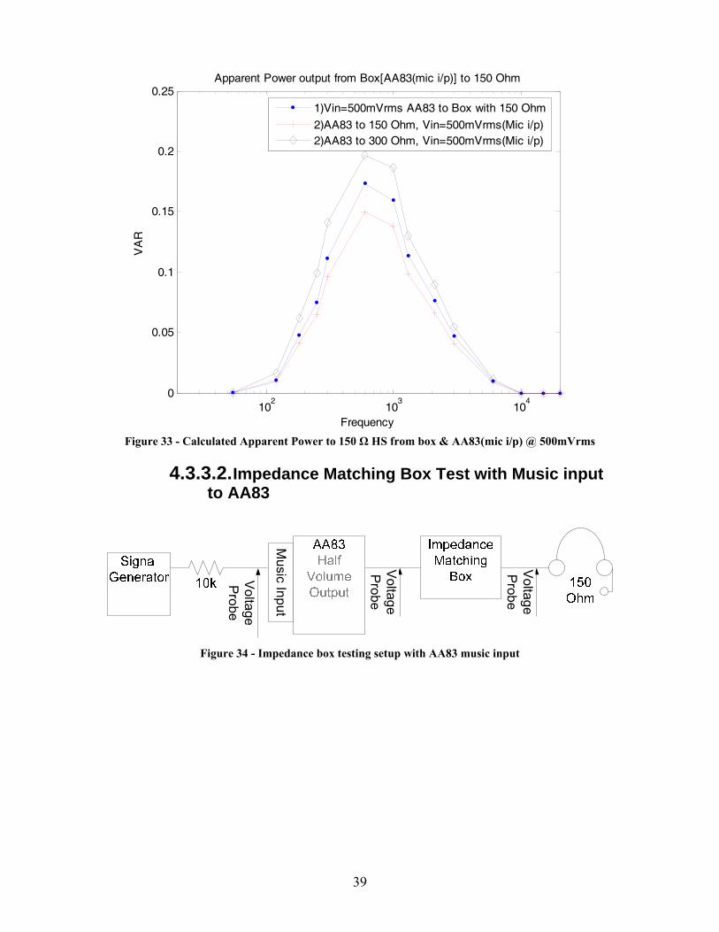
the AA83 was using the microphone input is shown by Figure 32 and Figure 33.
36
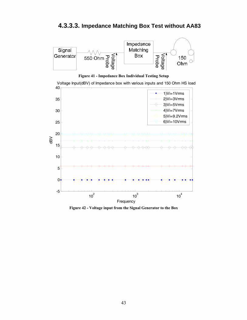
Measurements were taken with the signal generator, at different voltage levels,
connected to the impedance box to determine the frequency response of the impedance
box alone. The test setup is shown by Figure 41. Voltage delivered by the signal
generator is shown by Figure 42, output voltage is shown in Figure 43, and voltage gain
is shown in Figure 44. Apparent power is shown by Figure 45.
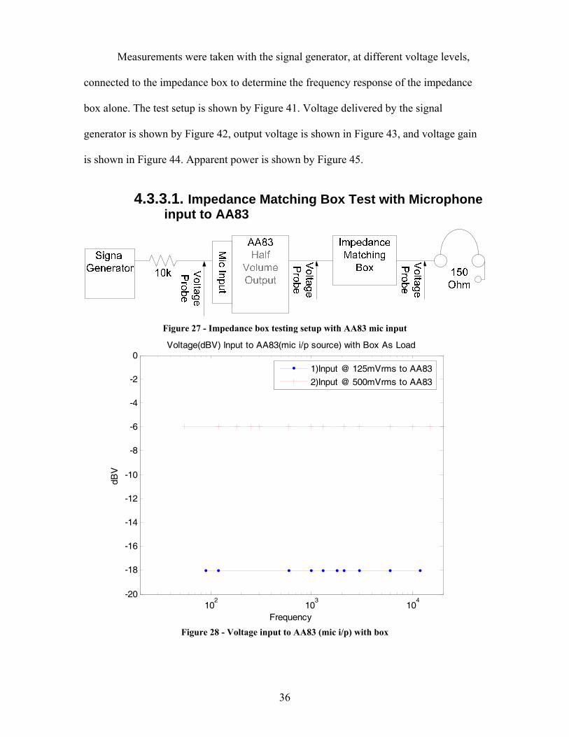
4.3.3.1. Impedance Matching Box Test with Microphone input to AA83
Figure 27 - Impedance box testing setup with AA83 mic input
102
103
104
-20
-18
-16
-14
-12
-10
-8
-6
-4
-2
0Voltage(dBV) Input to AA83(mic i/p source) with Box As Load
Frequency
dBV
1)Input @ 125mVrms to AA83
2)Input @ 500mVrms to AA83
Figure 28 - Voltage input to AA83 (mic i/p) with box
37
102
103
104
-25
-20
-15
-10
-5
0
5
10
15
20
25
30Voltage(dBV) Output of AA83(mic i/p source) with Box as Load
Frequency
dBV
1)Output @ 125mVrms(in)
2)Output @ 500mVrms(in)
Figure 29 - Frequency Response of AA83 (mic i/p) with Impedance box as load
102
103
104
-25
-20
-15
-10
-5
0
5
10
15
20
25
30Voltage(dBV) Output of Box from AA83(mic i/p source)
Frequency
dBV
1)Output @ 125mVrms(in to AA83)
2)Output @ 500mVrms(in to AA83)
Figure 30 - Frequency Response of Impedance box driven by the AA83(mic i/p) with 150 Ohm
headset load
38
102
103
104
-5
0
5
10
15
20
25
30
35
40Voltage Gain(dB) of AA83(mic i/p source), Box, & Overall Gain
Frequency
dB
1)AA83 Gain @ 125mVrms(in)2)AA83 Gain @ 500mVrms(in)
3)Box Gain @ 125mVrms(in)
4)Box Gain @ 500mVrms(in)
5)Overall Gain @ 125mVrms(in)6)Overall Gain @ 500mVrms(in)
Figure 31 - Calculated Voltage gain of AA83(mic i/p), box, & overall gain
102
103
104
0
0.002
0.004
0.006
0.008
0.01
0.012
0.014
0.016
0.018
0.02Apparent Power output from Box[AA83(mic i/p)] to 150 Ohm
Frequency
VA
R
1)Vin=125mVrms AA83 to Box with 150 Ohm
2)AA83 to 150 Ohm, Vin=125mVrms(Mic i/p)2)AA83 to 300 Ohm, Vin=125mVrms(Mic i/p)
Figure 32 - Calculated Apparent Power to 150 Ω HS from box & AA83(mic i/p) @ 125mVrms
39
102
103
104
0
0.05
0.1
0.15
0.2
0.25Apparent Power output from Box[AA83(mic i/p)] to 150 Ohm
Frequency
VA
R
1)Vin=500mVrms AA83 to Box with 150 Ohm
2)AA83 to 150 Ohm, Vin=500mVrms(Mic i/p)2)AA83 to 300 Ohm, Vin=500mVrms(Mic i/p)
Figure 33 - Calculated Apparent Power to 150 Ω HS from box & AA83(mic i/p) @ 500mVrms
4.3.3.2. Impedance Matching Box Test with Music input to AA83
Voltage
Probe
Voltage
Probe
Voltage
Probe
Music Input
Figure 34 - Impedance box testing setup with AA83 music input
40
102
103
104
-2
-1
0
1
2
3
4
5
6Voltage(dBV) Input to AA83(music i/p source) with Box As Load
Frequency
dBV
1)Input @ 900mVrms to AA83
2)Input @ 1.5Vrms to AA83
Figure 35 - Voltage input to AA83 (music i/p) with Impedance box as load
102
103
104
-15
-10
-5
0
5Voltage(dBV) Output of AA83(music i/p source) with Box as Load
Frequency
dBV
1)Output @ 900mVrms(in)
2)Output @ 1.5Vrms(in)
Figure 36 - Frequency Response of AA83 (music i/p) with Impedance box as load
41
102
103
104
-15
-10
-5
0
5Voltage(dBV) Output of Box from AA83(music i/p source)
Frequency
dBV
1)Output @ 900mVrms(in to AA83)
2)Output @ 1.5Vrms(in to AA83)
Figure 37 - Frequency Response of Impedance box driven by AA83(music i/p) and 150 Ohm headset
load
102
103
104
-20
-15
-10
-5
0
5
10
15
20Voltage Gain(dB) of AA83(music i/p source), Box, & Overall Gain
Frequency
dB
1)AA83 Gain @ 900mVrms(in)2)AA83 Gain @ 1.5Vrms(in)
3)Box Gain @ 900mVrms(in)
4)Box Gain @ 1.5Vrms(in)
5)Overall Gain @ 900mVrms(in)6)Overall Gain @ 1.5Vrms(in)
Figure 38 - Calculated Voltage gain of AA83(music i/p), box, & overall gain
42
102
103
104
0
0.5
1
1.5
2
2.5x 10
-3 Apparent Power output from Box[AA83(music i/p)] to 150 Ohm
Frequency
VA
1)Vin=900mVrms AA83 to Box with 150 Ohm
2)AA83 to 150 Ohm, Vin=900mVrms(Music i/p)2)AA83 to 300 Ohm, Vin=900mVrms(Music i/p)
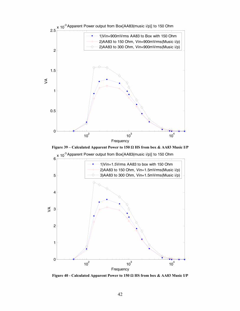
Figure 39 – Calculated Apparent Power to 150 Ω HS from box & AA83 Music I/P
102
103
104
0
1
2
3
4
5
6x 10
-3 Apparent Power output from Box[AA83(music i/p)] to 150 Ohm
Frequency
VA
1)Vin=1.5Vrms AA83 to box with 150 Ohm
2)AA83 to 150 Ohm, Vin=1.5mVrms(Music i/p)3)AA83 to 300 Ohm, Vin=1.5mVrms(Music i/p)
Figure 40 - Calculated Apparent Power to 150 Ω HS from box & AA83 Music I/P
43
4.3.3.3. Impedance Matching Box Test without AA83
Voltage
Probe
Voltage
Probe
Figure 41 - Impedance Box Individual Testing Setup
102
103
104
-5
0
5
10
15
20
25
30
35
40Voltage Input(dBV) of Impedance box with various inputs and 150 Ohm HS load
Frequency
dBV
1)Vi=1Vrms2)Vi=3Vrms
3)Vi=5Vrms
4)Vi=7Vrms
5)Vi=9.2Vrms6)Vi=10Vrms
Figure 42 - Voltage input from the Signal Generator to the Box
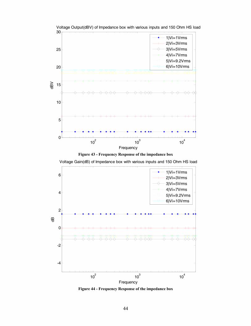
44
102
103
104
0
5
10
15
20
25
30Voltage Output(dBV) of Impedance box with various inputs and 150 Ohm HS load
Frequency
dBV
1)Vi=1Vrms2)Vi=3Vrms
3)Vi=5Vrms
4)Vi=7Vrms
5)Vi=9.2Vrms6)Vi=10Vrms
Figure 43 - Frequency Response of the impedance box
102
103
104
-4
-2
0
2
4
6
Voltage Gain(dB) of Impedance box with various inputs and 150 Ohm HS load
Frequency
dB
1)Vi=1Vrms2)Vi=3Vrms
3)Vi=5Vrms
4)Vi=7Vrms
5)Vi=9.2Vrms6)Vi=10Vrms
Figure 44 - Frequency Response of the impedance box
45
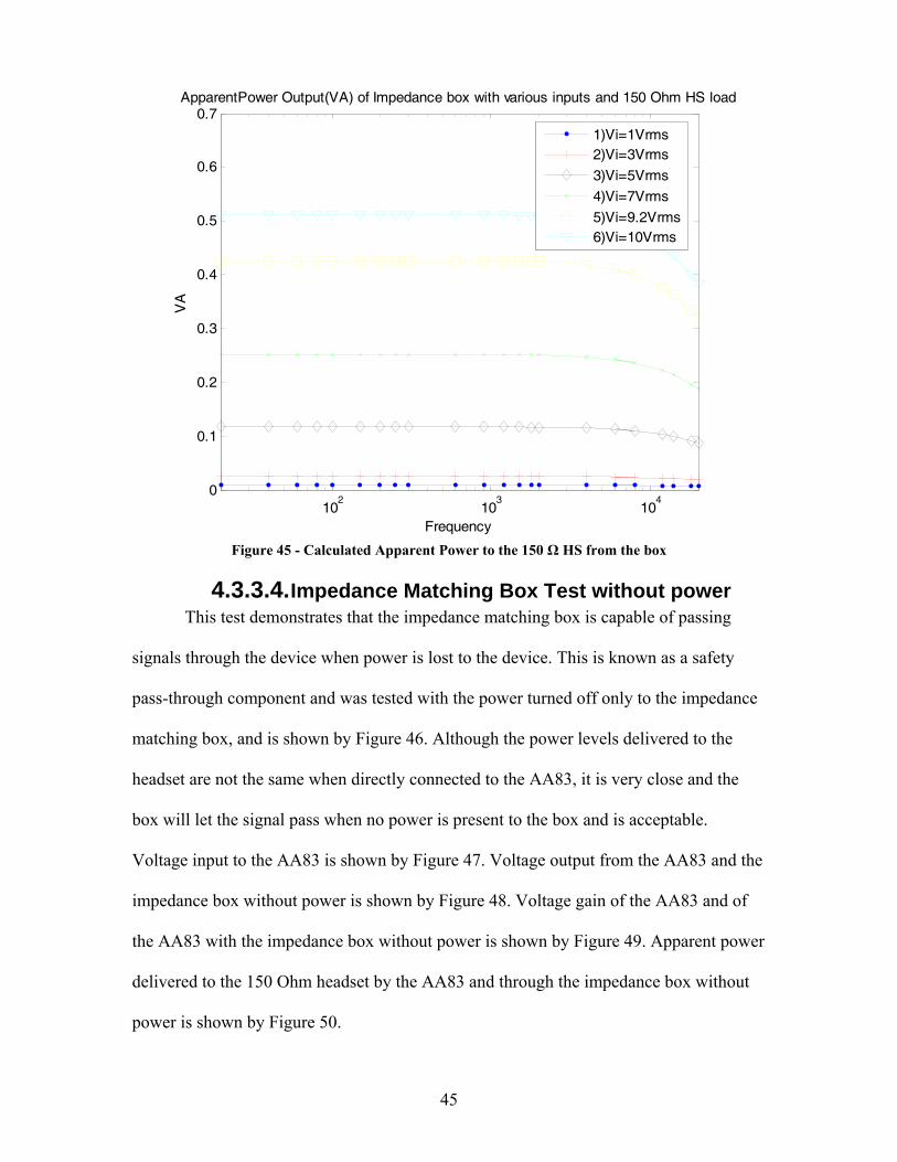
102
103
104
0
0.1
0.2
0.3
0.4
0.5
0.6
0.7ApparentPower Output(VA) of Impedance box with various inputs and 150 Ohm HS load
Frequency
VA
1)Vi=1Vrms2)Vi=3Vrms
3)Vi=5Vrms
4)Vi=7Vrms
5)Vi=9.2Vrms6)Vi=10Vrms
Figure 45 - Calculated Apparent Power to the 150 Ω HS from the box
4.3.3.4. Impedance Matching Box Test without power This test demonstrates that the impedance matching box is capable of passing
signals through the device when power is lost to the device. This is known as a safety
pass-through component and was tested with the power turned off only to the impedance
matching box, and is shown by Figure 46. Although the power levels delivered to the
headset are not the same when directly connected to the AA83, it is very close and the
box will let the signal pass when no power is present to the box and is acceptable.
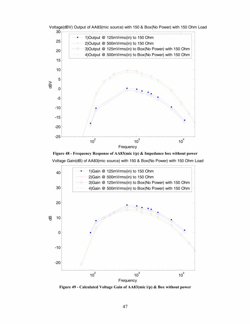
Voltage input to the AA83 is shown by Figure 47. Voltage output from the AA83 and the
impedance box without power is shown by Figure 48. Voltage gain of the AA83 and of
the AA83 with the impedance box without power is shown by Figure 49. Apparent power
delivered to the 150 Ohm headset by the AA83 and through the impedance box without
power is shown by Figure 50.
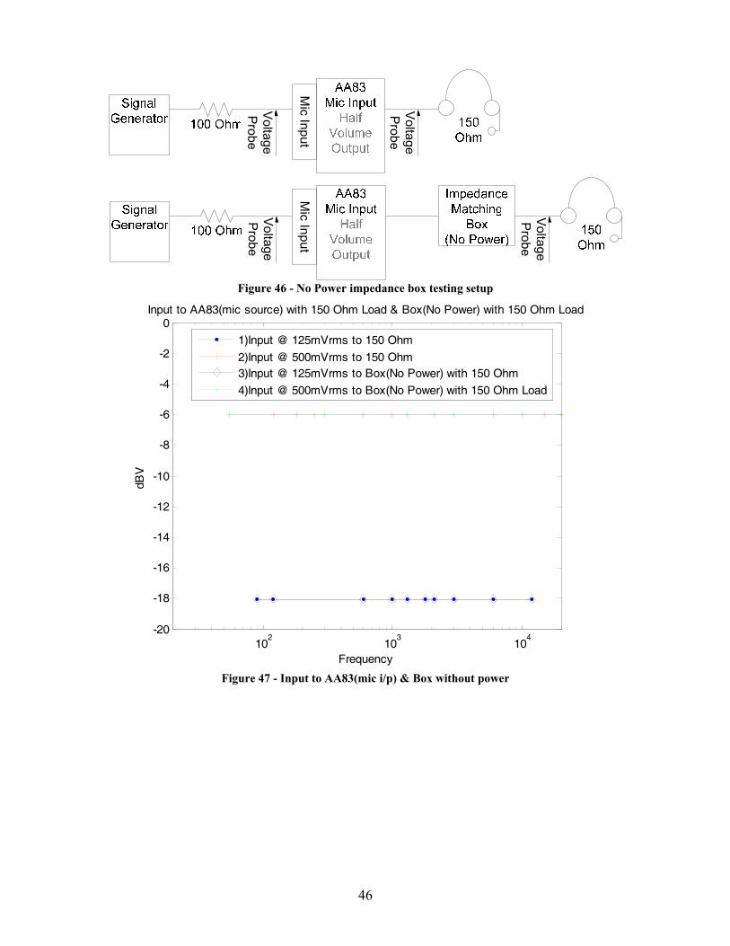
46
Voltage
Probe
Voltage
Probe
Voltage
Probe
Voltage
Probe
Mic Input
Mic Input
Figure 46 - No Power impedance box testing setup
102
103
104
-20
-18
-16
-14
-12
-10
-8
-6
-4
-2
0Input to AA83(mic source) with 150 Ohm Load & Box(No Power) with 150 Ohm Load
Frequency
dBV
1)Input @ 125mVrms to 150 Ohm
2)Input @ 500mVrms to 150 Ohm3)Input @ 125mVrms to Box(No Power) with 150 Ohm
4)Input @ 500mVrms to Box(No Power) with 150 Ohm Load
Figure 47 - Input to AA83(mic i/p) & Box without power
47
102
103
104
-25
-20
-15
-10
-5
0
5
10
15
20
25
30Voltage(dBV) Output of AA83(mic source) with 150 & Box(No Power) with 150 Ohm Load
Frequency
dBV
1)Output @ 125mVrms(in) to 150 Ohm
2)Output @ 500mVrms(in) to 150 Ohm3)Output @ 125mVrms(in) to Box(No Power) with 150 Ohm
4)Output @ 500mVrms(in) to Box(No Power) with 150 Ohm
Figure 48 - Frequency Response of AA83(mic i/p) & Impedance box without power
102
103
104
-20
-10
0
10
20
30
40
Voltage Gain(dB) of AA83(mic source) with 150 & Box(No Power) with 150 Ohm Load
Frequency
dB
1)Gain @ 125mVrms(in) to 150 Ohm
2)Gain @ 500mVrms(in) to 150 Ohm3)Gain @ 125mVrms(in) to Box(No Power) with 150 Ohm
4)Gain @ 500mVrms(in) to Box(No Power) with 150 Ohm
Figure 49 - Calculated Voltage Gain of AA83(mic i/p) & Box without power
48
102
103
104
0
0.01
0.02
0.03
0.04
0.05
0.06
0.07
0.08Apparent Power output from AA83(mic source) to 150 & Box(No Power) with 150 Ohm
Frequency
VA
R
1)Apparent Power @ 125mVrms(in) to 150 Ohm
2)Apparent Power @ 125mVrms(in) to Box(No Power) with 150 Ohm3)Apparent Power @ 500mVrms(in) to 150 Ohm
4)Apparent Power @ 500mVrms(in) to Box(No Power) with 150 Ohm
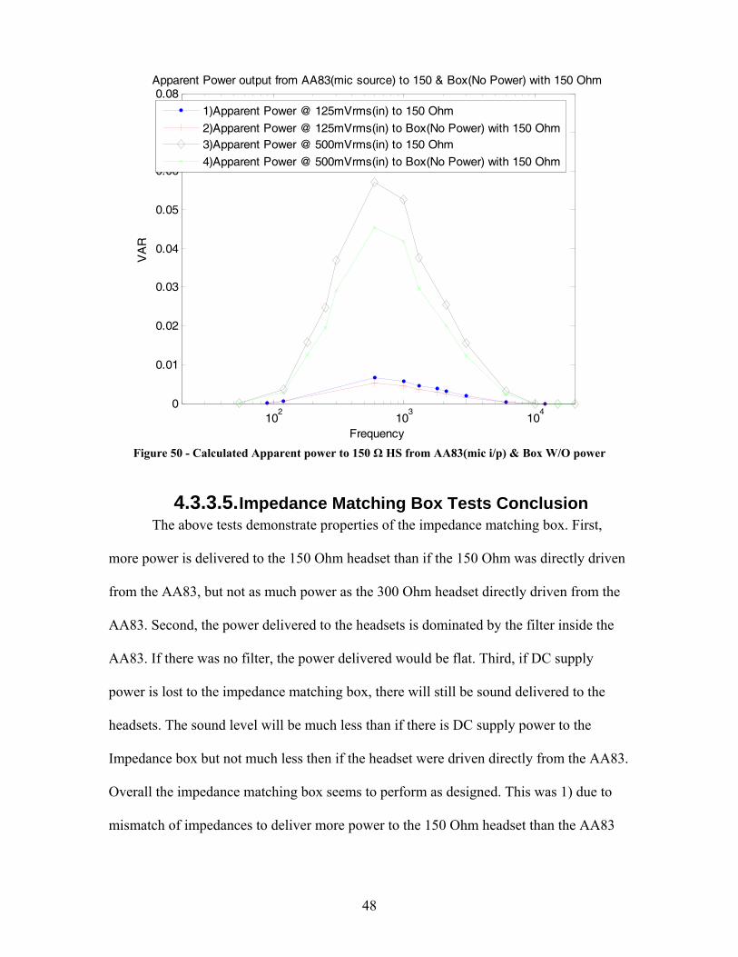
Figure 50 - Calculated Apparent power to 150 Ω HS from AA83(mic i/p) & Box W/O power
4.3.3.5. Impedance Matching Box Tests Conclusion The above tests demonstrate properties of the impedance matching box. First,
more power is delivered to the 150 Ohm headset than if the 150 Ohm was directly driven
from the AA83, but not as much power as the 300 Ohm headset directly driven from the
AA83. Second, the power delivered to the headsets is dominated by the filter inside the
AA83. If there was no filter, the power delivered would be flat. Third, if DC supply
power is lost to the impedance matching box, there will still be sound delivered to the
headsets. The sound level will be much less than if there is DC supply power to the
Impedance box but not much less then if the headset were driven directly from the AA83.
Overall the impedance matching box seems to perform as designed. This was 1) due to
mismatch of impedances to deliver more power to the 150 Ohm headset than the AA83
49
would allow and 2) to allow operation when DC supply power is lost to the impedance
matching box.
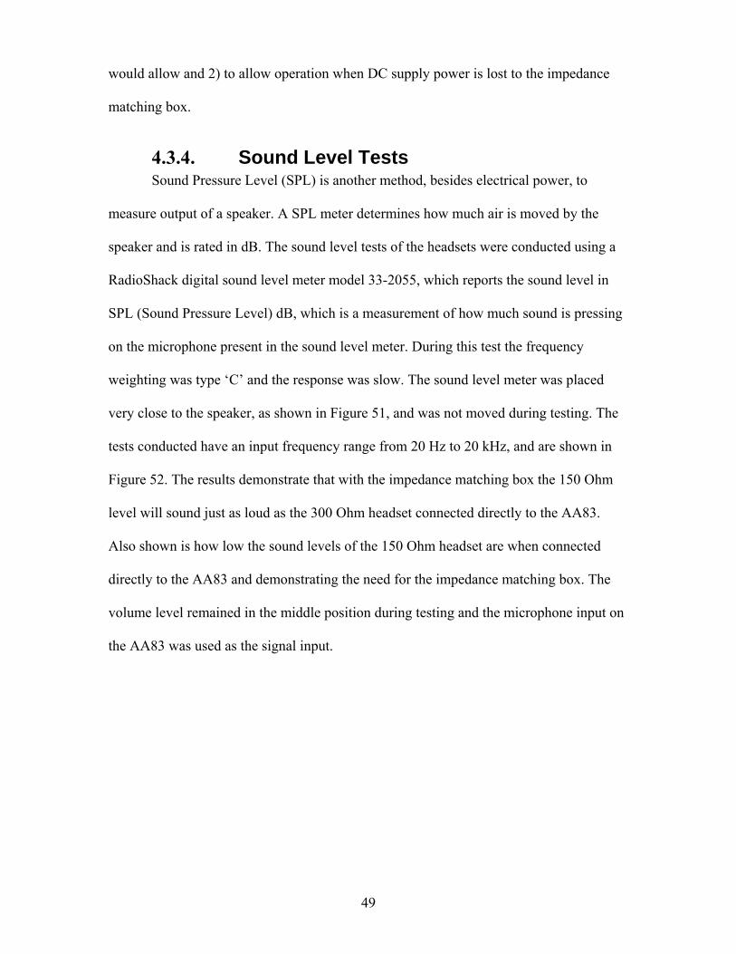
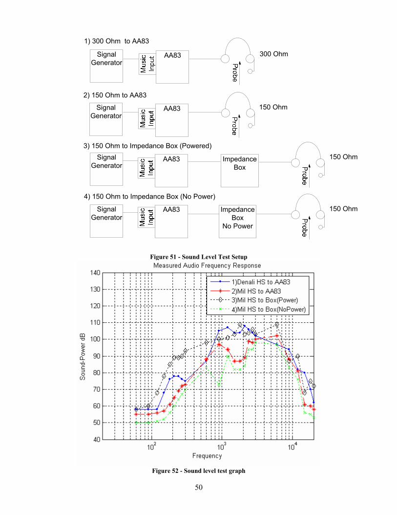
4.3.4. Sound Level Tests Sound Pressure Level (SPL) is another method, besides electrical power, to
measure output of a speaker. A SPL meter determines how much air is moved by the
speaker and is rated in dB. The sound level tests of the headsets were conducted using a
RadioShack digital sound level meter model 33-2055, which reports the sound level in
SPL (Sound Pressure Level) dB, which is a measurement of how much sound is pressing
on the microphone present in the sound level meter. During this test the frequency
weighting was type ‘C’ and the response was slow. The sound level meter was placed
very close to the speaker, as shown in Figure 51, and was not moved during testing. The
tests conducted have an input frequency range from 20 Hz to 20 kHz, and are shown in
Figure 52. The results demonstrate that with the impedance matching box the 150 Ohm
level will sound just as loud as the 300 Ohm headset connected directly to the AA83.
Also shown is how low the sound levels of the 150 Ohm headset are when connected
directly to the AA83 and demonstrating the need for the impedance matching box. The
volume level remained in the middle position during testing and the microphone input on
the AA83 was used as the signal input.
50
300 OhmSignal Generator
AA83
150 OhmSignal Generator
AA83
150 OhmSignal Generator
Impedance Box
AA83
150 OhmSignal Generator
AA83
1) 300 Ohm to AA83
2) 150 Ohm to AA83
3) 150 Ohm to Impedance Box (Powered)
4) 150 Ohm to Impedance Box (No Power)
Impedance Box
No Power
Figure 51 - Sound Level Test Setup
Figure 52 - Sound level test graph
51
4.3.5. Dynamic Microphone Amplifier Circuit Tests
The dynamic microphone amplifier test consists of frequency responses (300Hz to
3 kHz, which estimates what a human voice can produce) in various points in the circuit
with and without a load. The signal generator did not output a low enough voltage for the
circuit, so an external circuit was required to drop the voltage level to acceptable levels
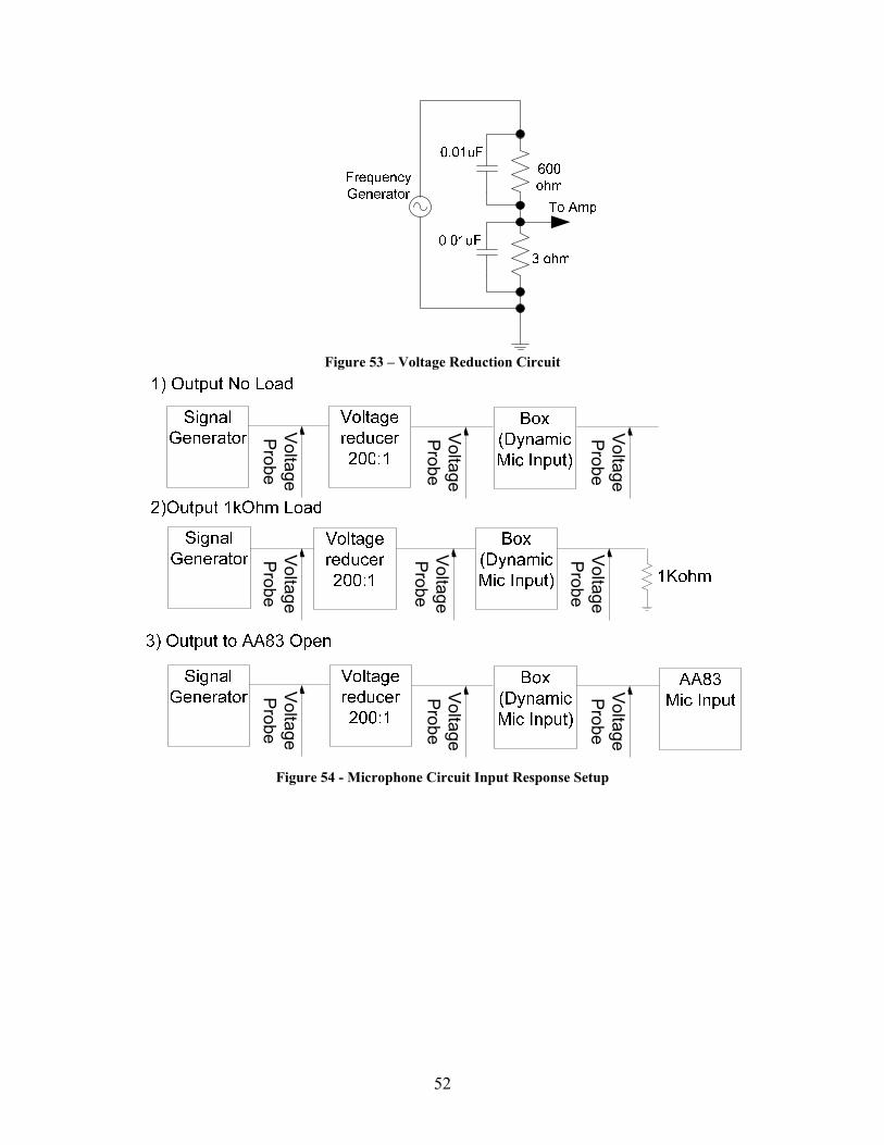
(~20mV). This circuit design of the voltage reducer, shown in Figure 53, needed
capacitors to filter the high frequency components that are not wanted and disrupted
testing during this measurement.
The voltage gain input frequency response of the microphone circuit test was
conducted to demonstrate the flat signal coming from the voltage reducer preformed as it
was designed. The test setup can be shown in Figure 54. The test setup involved the open
loop, 1 k Ohm resistive load, and the NAT AA83 microphone input response of the
impedance matching box with the dynamic microphone component.
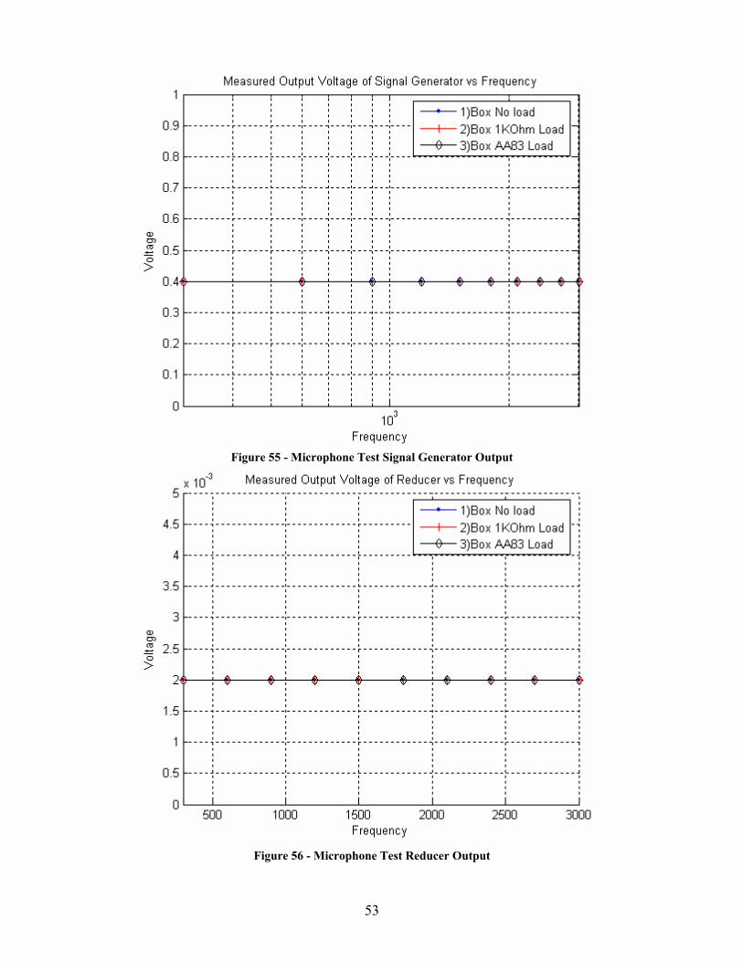
The voltage of the signal generator is shown by Figure 55. The output voltage of
the reduction circuit is shown by Figure 56. The inputs and outputs of the impedance
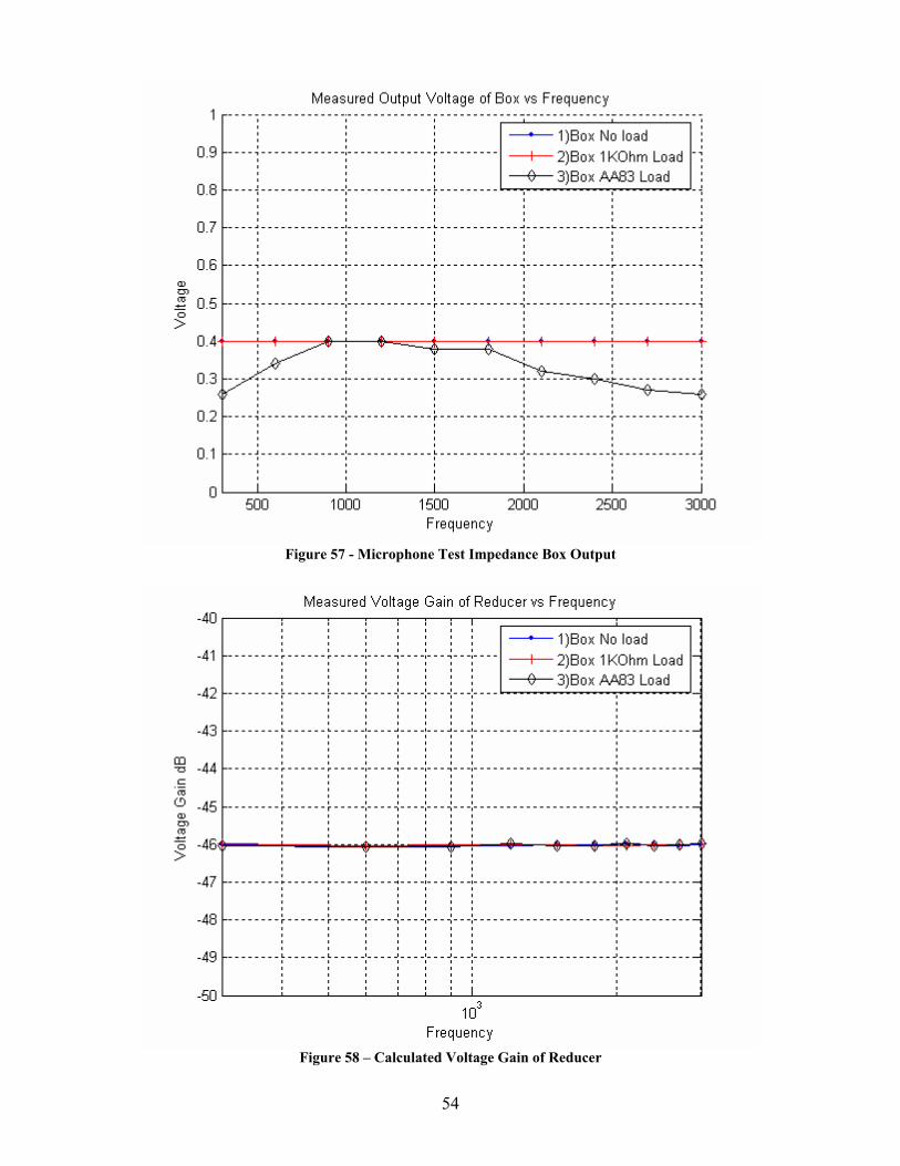
matching box in this test were the dynamic microphone input and the microphone output.
The output of the impedance box is shown by Figure 57. The voltage gain of the reducer,
shown by Figure 58, was calculated by the input to the reducer and the output of the
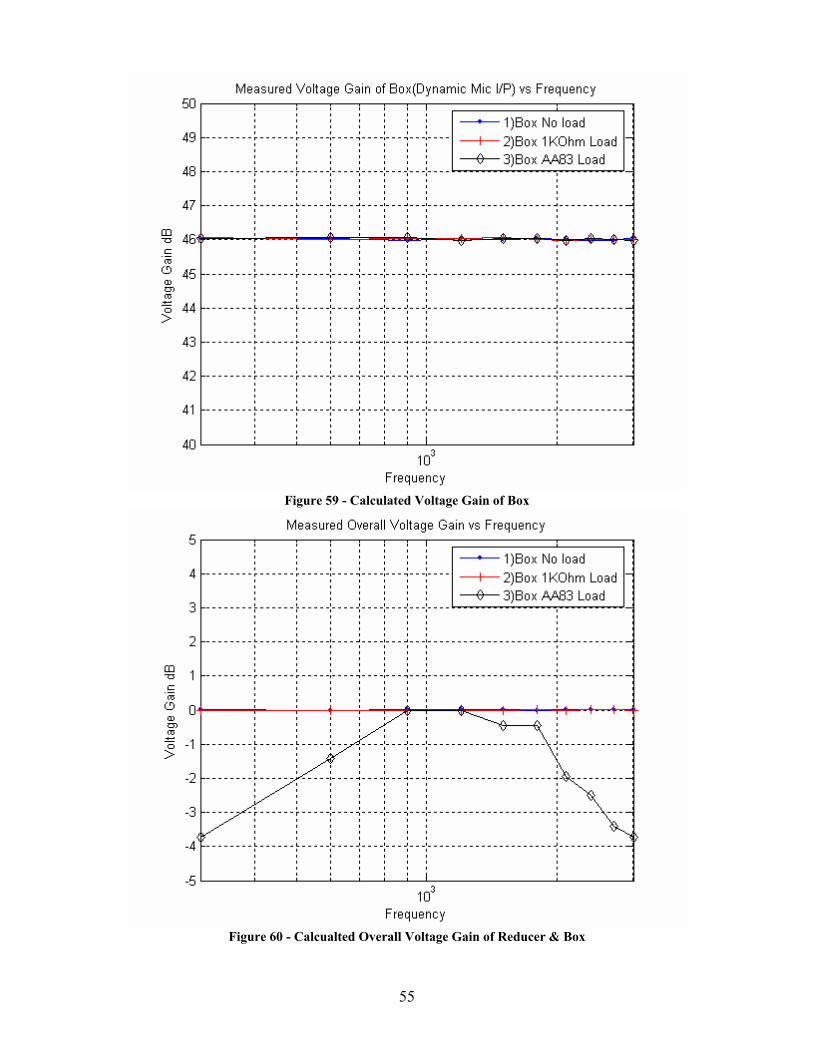
reducer. The voltage gain of the dynamic microphone circuitry of the impedance
matching box, shown by Figure 59, was calculated with the input to the box and its
output. The overall gain of the entire circuit is shown by Figure 60, and was calculated
from the signal generator input and the impedance box output.
52
Figure 53 – Voltage Reduction Circuit
Voltage
Probe
Voltage
Probe
Voltage
Probe
Voltage
Probe
Voltage
Probe
Voltage
Probe
Voltage
Probe
Voltage
Probe
Voltage
Probe
Figure 54 - Microphone Circuit Input Response Setup
53
Figure 55 - Microphone Test Signal Generator Output
Figure 56 - Microphone Test Reducer Output
54
Figure 57 - Microphone Test Impedance Box Output
Figure 58 – Calculated Voltage Gain of Reducer
55
Figure 59 - Calculated Voltage Gain of Box
Figure 60 - Calcualted Overall Voltage Gain of Reducer & Box
56
4.3.5.1. Dynamic Microphone Amplifier Circuit Tests Conclusion
The above test demonstrates that the dynamic microphone amplifier in the
impedance matching box perform as designed. The goal of the design was to have a
constant voltage gain of 200 for the input. The final test where the NAT AA83 received
input from the impedance matching box demonstrates that the AA83 contains a filter that
is centered around the middle of the human voice range, and does not affect the
performance of the impedance matching box.
4.3.6. Overall Tests Conclusion The measurements taken demonstrate two dominate properties. First, the AA83
clearly has a filter that is most likely used to remove unwanted frequencies from being
attenuated through the device. The good part about this filter is that unwanted noise will
not be propagating through the device creating a cleaner sound. The bad part is that very
high and very low frequencies are removed or greatly hindered, which will reduce sound
quality from music sources. Second, the impedance matching device and its underlying
circuitry perform as it was designed. The impedance matching device boosted the power,
which in turn boosted the sound output to let 150 Ohm appear almost as loud as 300 Ohm
headsets.
The microphone amplification circuit demonstrated a voltage gain of 46 dB or
200, and the headset circuit brings the power output of the 150 Ohm headset into range
similar to that of the 300 Ohm headset. Overall the use of a transformer would probably
have produced similar results as the op-amps. The advantage of the op-amp is that a
future version could easily increase the voltage levels so that a 150 Ohm headset was just
as loud or louder as a 300 Ohm headset.
57
4.4. Conclusion
Civilian and military aircraft headsets have evolved into two different connection
and impedance standards that are incompatible. Needed, but not available, was a device
that would allow for operators to use their favorite type of headset on any intercom.
This thesis reports on an intercom system which when tested, demonstrated full
functionality while allowing for expandability of the intercom system. This design allows
an operator to use whichever type of headset they choose, based on comfort or feature
levels. This should help ensure satisfaction with the complete Project Oculus system.
In conclusion, an intercom system was designed, constructed, and tested that uses
military and civilian headsets to communicate both internally for Project Oculus and
externally to the C-130 crew and provides support for a headset to be connected
externally of the operator station
4.5. Future Work
Time and budget constraints did not allow for certain items to be considered in
this thesis. Testing of more headsets from different manufacturers with the impedance
matching circuit would allow for more compatibility. The layout of the PCB (shown in
Appendix A) could be much smaller and more efficiently laid out. The use of surface
mount technology and smaller components would reduce board size. A loud speaker with
proper electrical connections needed implemented and installed. Finally, radio switches
need designed and installed to accommodate multiple radios for each person in the
operator station.

58
Works Cited [1]. The 20th Century's Greatest Airlifter Will Also Be the 21st Century's Greatest.
http://www.lockheedmartin.com. 2004. [2]. Wowczuk, Zenovy, “Design of a Standardized Sensor Platform for a C-130
Aircraft”, Thesis, August 2004. West Virginia University, C-130 Project Oculus. [3]. Feragotti, Lawrence A., “Sensitiviy Analysis of the C-130 Sensor Deployment
System Arm using the Finite Element Method”, Thesis, 2004, West Virginia University, C-130 Project Oculus.
[4]. Naternicola, Adam. “Dynamic Modal Analysis and Optimization of C-130 Project
Oculus’ Mechanical/Pod Sensor Deployment System using Finite Element Method”, Thesis, May 2004, West Virginia University, C-130 Project Oculus.
[5]. Shawlee, Walter. “Avionics System Design: Voodoo Audio”.
http://www.aviationtoday.com. [6]. Hayes, Robert. “Control System design for a C-130 Ro-Ro Sensor Deployment
Platform”, Thesis, May 2004, West Virginia University, C-130 Project Oculus. [7]. Communication/Navigation Systems & Specifications. http://www.aviationnow.com. [8]. Northern Airborne Technology AA83-001 Inter Music Stereo Intercom Data
Manual. April 2004, http://www.northernairborne.com. [9]. Northern Airborne Technology AA36-100 Digital Tie Line Adapter Data Manual.
November 2003, http://www.northernairborne.com. [10]. National Semiconductor LM358. http://www.national.com. March 2004. [11]. National Semiconductor LM386 Information page. http://www.national.com.
August 2000. [12]. National Semiconductor LM340 Information page. http://www.national.com.
August 2004. [13]. “Impedance Matching: A Primer. Electus Distributin”, 2001.
http://www.electusdistribution.com.au.

59
[14]. Phoenix Contact terminals specifications. http://eshop.phoenixcontact.com. June 2003
[15]. E-Switch specifications. http://www.e-switch.com. [16]. Dialight LED datasheet. http://www.dialight.com. [17]. Hirose HR10A-10R-10S Data Sheet. http://www.hirose.co.jp. [18]. Flightcom Denali ANR Headset Specifications. http://flightcom.net.
60
Appendix A Custom Impedance Matching Circuit
A.1 Headset Impedance Matching Circuit Design
Impedance matching of speakers can be achieved by two different methods. An
impedance matching transformer can be placed between the amp and the speaker or the
signal may be buffered by an amplifier which changes the impedance. The disadvantage
of using the transformer is that low frequencies can be attenuated, which degrades audio
signals. Amplifiers require power, and a bit of external circuitry, but don’t necessarily
filter frequencies. Each of the methods has advantages and disadvantages, but for this
design the amplifier method was chosen. The goal was to have a somewhat flat frequency
response from 20 Hz to 20 kHz and to match impedances with an op-amp (Operational
Amplifier).
Transformers provide a passive component that does not require power or control.
They also can be physically large and heavy mainly because they require many windings
around an iron core. Transformers are rated by the number of turns, what type and size of
wire, and the size of the iron core. Many different transformers were found that would
possibly allow for passive impedance matching, but they were too large, and heavy.
Transformers also have a specific frequency response, which if not matched to the
application could be a hindering factor.
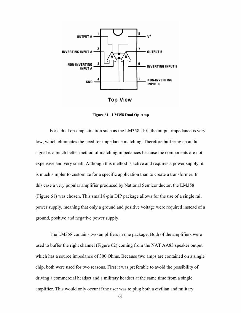
61
Figure 61 - LM358 Dual Op-Amp
For a dual op-amp situation such as the LM358 [10], the output impedance is very
low, which eliminates the need for impedance matching. Therefore buffering an audio
signal is a much better method of matching impedances because the components are not
expensive and very small. Although this method is active and requires a power supply, it
is much simpler to customize for a specific application than to create a transformer. In
this case a very popular amplifier produced by National Semiconductor, the LM358
(Figure 61) was chosen. This small 8-pin DIP package allows for the use of a single rail
power supply, meaning that only a ground and positive voltage were required instead of a
ground, positive and negative power supply.
The LM358 contains two amplifiers in one package. Both of the amplifiers were
used to buffer the right channel (Figure 62) coming from the NAT AA83 speaker output
which has a source impedance of 300 Ohms. Because two amps are contained on a single
chip, both were used for two reasons. First it was preferable to avoid the possibility of
driving a commercial headset and a military headset at the same time from a single
amplifier. This would only occur if the user was to plug both a civilian and military
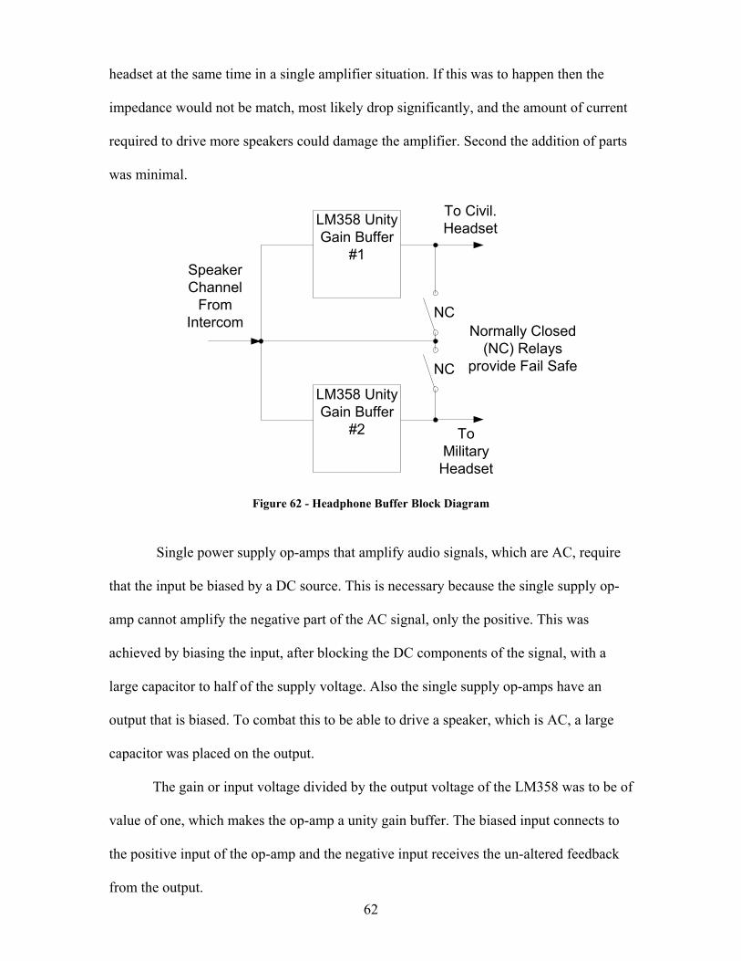
62
headset at the same time in a single amplifier situation. If this was to happen then the
impedance would not be match, most likely drop significantly, and the amount of current
required to drive more speakers could damage the amplifier. Second the addition of parts
was minimal.
LM358 Unity Gain Buffer
#2
LM358 Unity Gain Buffer
#1Speaker Channel
From Intercom
To Civil. Headset
To Military
Headset
NC
NC
Normally Closed (NC) Relays
provide Fail Safe
Figure 62 - Headphone Buffer Block Diagram
Single power supply op-amps that amplify audio signals, which are AC, require
that the input be biased by a DC source. This is necessary because the single supply op-
amp cannot amplify the negative part of the AC signal, only the positive. This was
achieved by biasing the input, after blocking the DC components of the signal, with a
large capacitor to half of the supply voltage. Also the single supply op-amps have an
output that is biased. To combat this to be able to drive a speaker, which is AC, a large
capacitor was placed on the output.
The gain or input voltage divided by the output voltage of the LM358 was to be of
value of one, which makes the op-amp a unity gain buffer. The biased input connects to
the positive input of the op-amp and the negative input receives the un-altered feedback
from the output.
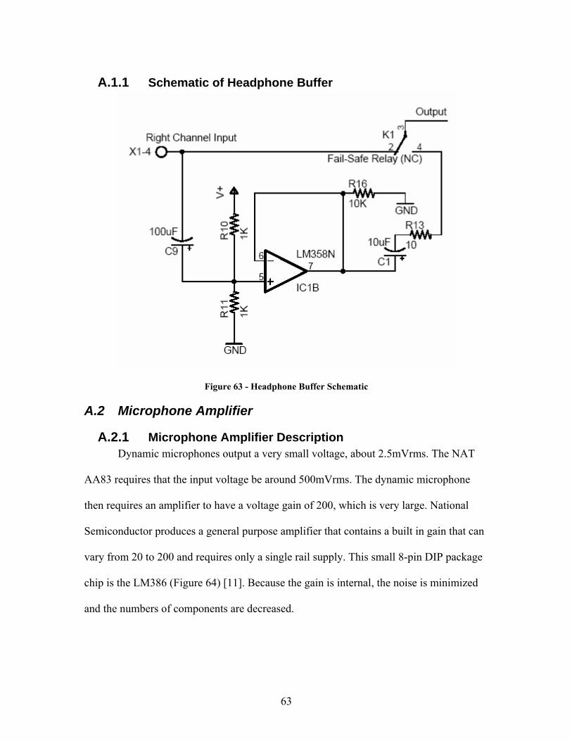
63
A.1.1 Schematic of Headphone Buffer
Figure 63 - Headphone Buffer Schematic
A.2 Microphone Amplifier
A.2.1 Microphone Amplifier Description Dynamic microphones output a very small voltage, about 2.5mVrms. The NAT
AA83 requires that the input voltage be around 500mVrms. The dynamic microphone
then requires an amplifier to have a voltage gain of 200, which is very large. National
Semiconductor produces a general purpose amplifier that contains a built in gain that can
vary from 20 to 200 and requires only a single rail supply. This small 8-pin DIP package
chip is the LM386 (Figure 64) [11]. Because the gain is internal, the noise is minimized
and the numbers of components are decreased.
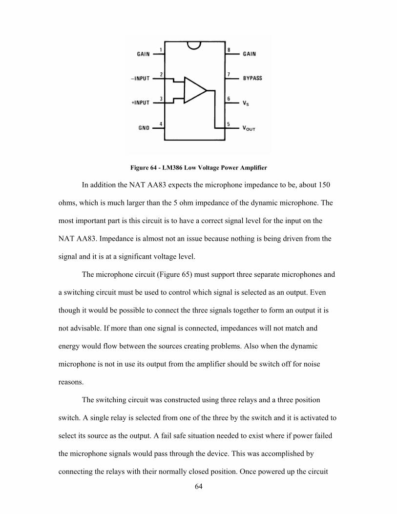
64
Figure 64 - LM386 Low Voltage Power Amplifier In addition the NAT AA83 expects the microphone impedance to be, about 150
ohms, which is much larger than the 5 ohm impedance of the dynamic microphone. The
most important part is this circuit is to have a correct signal level for the input on the
NAT AA83. Impedance is almost not an issue because nothing is being driven from the
signal and it is at a significant voltage level.
The microphone circuit (Figure 65) must support three separate microphones and
a switching circuit must be used to control which signal is selected as an output. Even
though it would be possible to connect the three signals together to form an output it is
not advisable. If more than one signal is connected, impedances will not match and
energy would flow between the sources creating problems. Also when the dynamic
microphone is not in use its output from the amplifier should be switch off for noise
reasons.
The switching circuit was constructed using three relays and a three position
switch. A single relay is selected from one of the three by the switch and it is activated to
select its source as the output. A fail safe situation needed to exist where if power failed
the microphone signals would pass through the device. This was accomplished by
connecting the relays with their normally closed position. Once powered up the circuit
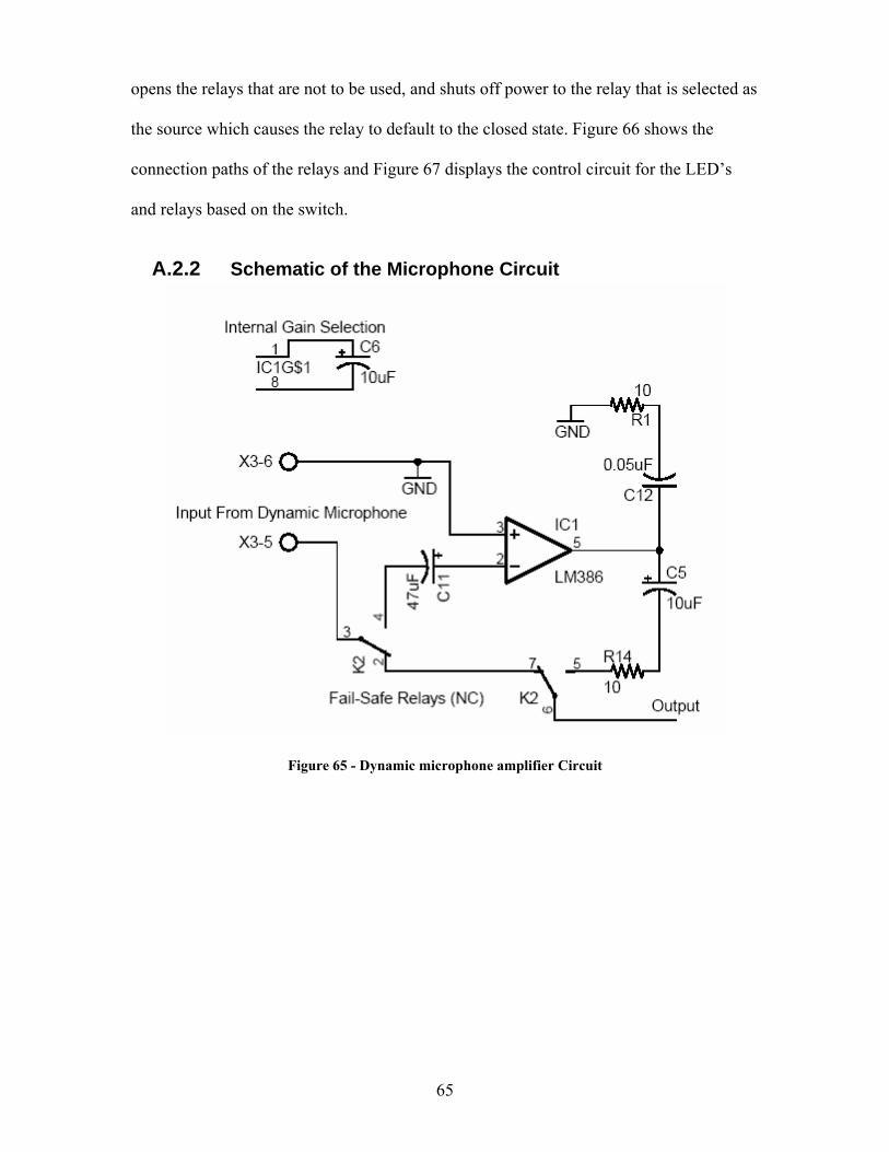
65
opens the relays that are not to be used, and shuts off power to the relay that is selected as
the source which causes the relay to default to the closed state. Figure 66 shows the
connection paths of the relays and Figure 67 displays the control circuit for the LED’s
and relays based on the switch.
A.2.2 Schematic of the Microphone Circuit
Figure 65 - Dynamic microphone amplifier Circuit
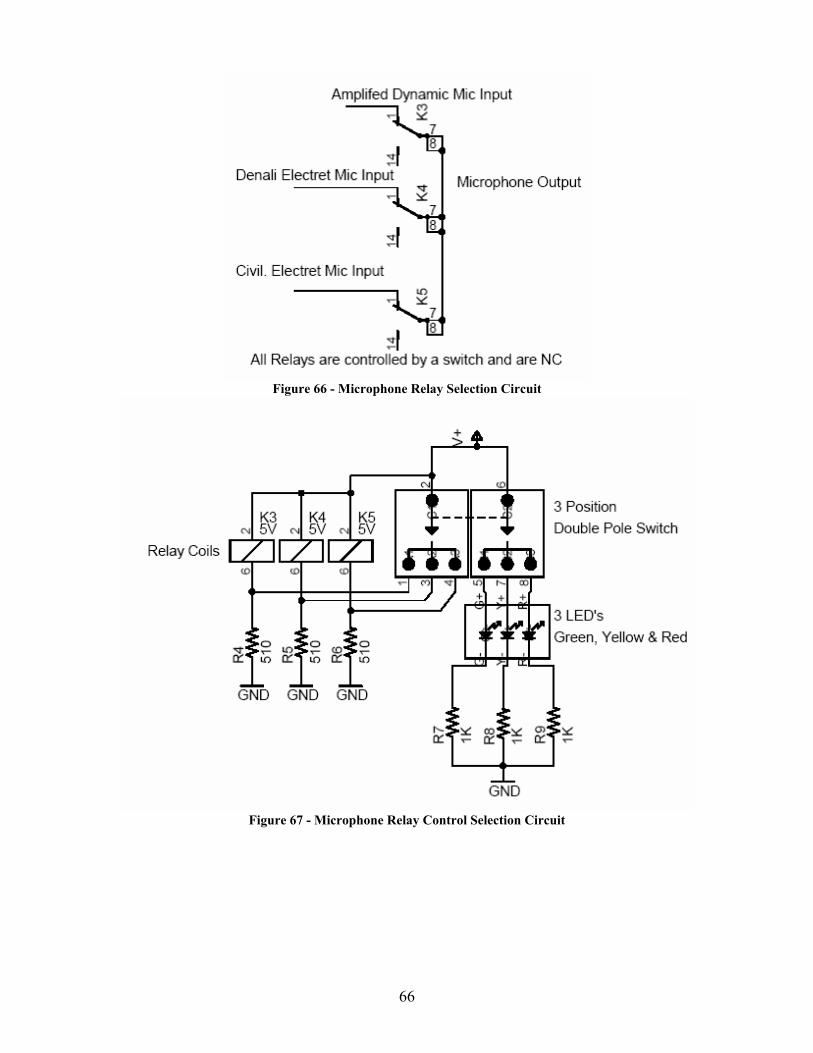
66
Figure 66 - Microphone Relay Selection Circuit
Figure 67 - Microphone Relay Control Selection Circuit
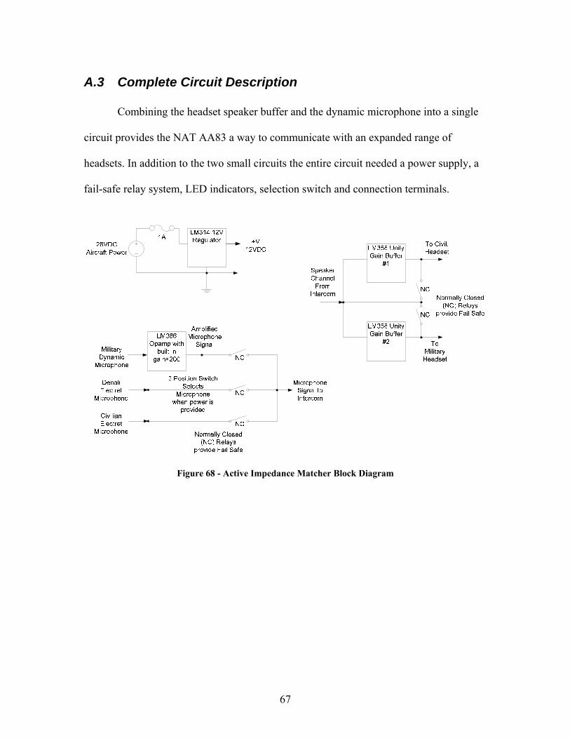
67
A.3 Complete Circuit Description Combining the headset speaker buffer and the dynamic microphone into a single
circuit provides the NAT AA83 a way to communicate with an expanded range of
headsets. In addition to the two small circuits the entire circuit needed a power supply, a
fail-safe relay system, LED indicators, selection switch and connection terminals.
Figure 68 - Active Impedance Matcher Block Diagram
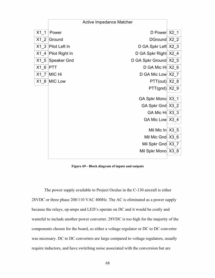
68
Active Impedance Matcher
X1_1X1_2X1_3X1_4X1_5X1_6X1_7X1_8
D GA Spkr Left
D Power X2_1X2_2X2_3X2_4X2_5X2_6X2_7X2_8
DGround
D GA Spkr RightD GA Spkr Ground
GA Spkr MonoGA Spkr Gnd
D GA Mic HiD GA Mic Low
PTT(out)
X3_1X3_2X3_3X3_4
X3_5
GA Mic HiGA Mic Low
X3_6X3_7X3_8Mil Spkr Mono
Mil Spkr Gnd
Mil Mic InMil Mic Gnd
PowerGround
Pilot Right InSpeaker GndPTTMIC HiMIC Low
Pilot Left In
PTT(gnd) X2_9
Figure 69 - Block diagram of inputs and outputs
The power supply available to Project Oculus in the C-130 aircraft is either
28VDC or three phase 208/110 VAC 400Hz. The AC is eliminated as a power supply
because the relays, op-amps and LED’s operate on DC and it would be costly and
wasteful to include another power converter. 28VDC is too high for the majority of the
components chosen for the board, so either a voltage regulator or DC to DC converter
was necessary. DC to DC converters are large compared to voltage regulators, usually
require inductors, and have switching noise associated with the conversion but are
69
extremely efficient. Most of these traits are unwanted on a small PCB that is meant for
noise free audio. A brute force, linear voltage regulator was chosen, even though they
have heat dissipation issues while conducting large amounts of current. The single chip
three pin LM340-12 [12] provides sufficient voltage regulation of 12VDC at a maximum
input of 35VDC and maximum output current of about 2A. The entire circuit of the
impedance matching uses approximately 200 mA at the worst case. The LM340-12 at the
highest PCB load will burn off approximately 3.2W of heat in the worst case, which is
easily taken care of by the heat sink on the PCB and the extra ground trace on the PCB
meant just for heat dissipation.
Power, in the form of 9-32VDC, must be provided to the Flightcom Denali ANR
(Active Noise Reduction) headset in order for the ANR to work. This is accomplished in
either one of two methods, both of which connect to the Impedance Matching PCB. The
selection is achieved by a jumper on the board which will select one or the other
methods. First power can be drawn as 28VDC from a shared 1A fuse with the impedance
matching board. This allows the LM340-12 to save on heat dissipation. Second the power
can come from the 12VDC which is regulated by the LM340-12. Either way is acceptable
and can be configured by the user.
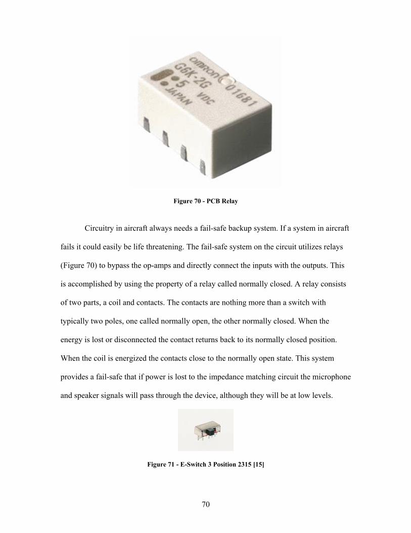
70
Figure 70 - PCB Relay
Circuitry in aircraft always needs a fail-safe backup system. If a system in aircraft
fails it could easily be life threatening. The fail-safe system on the circuit utilizes relays
(Figure 70) to bypass the op-amps and directly connect the inputs with the outputs. This
is accomplished by using the property of a relay called normally closed. A relay consists
of two parts, a coil and contacts. The contacts are nothing more than a switch with
typically two poles, one called normally open, the other normally closed. When the
energy is lost or disconnected the contact returns back to its normally closed position.
When the coil is energized the contacts close to the normally open state. This system
provides a fail-safe that if power is lost to the impedance matching circuit the microphone
and speaker signals will pass through the device, although they will be at low levels.
Figure 71 - E-Switch 3 Position 2315 [15]
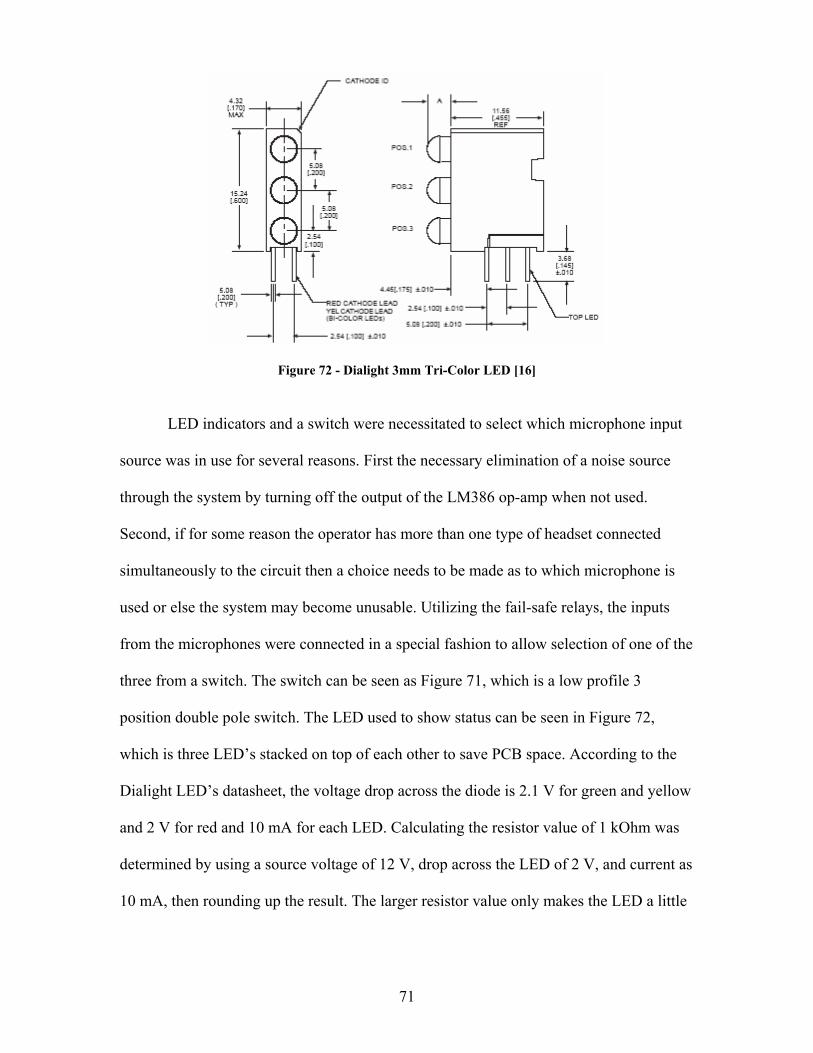
71
Figure 72 - Dialight 3mm Tri-Color LED [16]
LED indicators and a switch were necessitated to select which microphone input
source was in use for several reasons. First the necessary elimination of a noise source
through the system by turning off the output of the LM386 op-amp when not used.
Second, if for some reason the operator has more than one type of headset connected
simultaneously to the circuit then a choice needs to be made as to which microphone is
used or else the system may become unusable. Utilizing the fail-safe relays, the inputs
from the microphones were connected in a special fashion to allow selection of one of the
three from a switch. The switch can be seen as Figure 71, which is a low profile 3
position double pole switch. The LED used to show status can be seen in Figure 72,
which is three LED’s stacked on top of each other to save PCB space. According to the
Dialight LED’s datasheet, the voltage drop across the diode is 2.1 V for green and yellow
and 2 V for red and 10 mA for each LED. Calculating the resistor value of 1 kOhm was
determined by using a source voltage of 12 V, drop across the LED of 2 V, and current as
10 mA, then rounding up the result. The larger resistor value only makes the LED a little
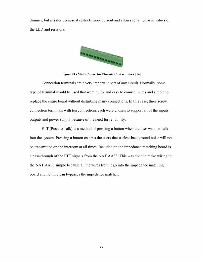
72
dimmer, but is safer because it restricts more current and allows for an error in values of
the LED and resistors.
Figure 73 - Multi Connector Phoenix Contact Block [14] Connection terminals are a very important part of any circuit. Normally, some
type of terminal would be used that were quick and easy to connect wires and simple to
replace the entire board without disturbing many connections. In this case, three screw
connection terminals with ten connections each were chosen to support all of the inputs,
outputs and power supply because of the need for reliability.
PTT (Push to Talk) is a method of pressing a button when the user wants to talk
into the system. Pressing a button ensures the users that useless background noise will not
be transmitted on the intercom at all times. Included on the impedance matching board is
a pass-through of the PTT signals from the NAT AA83. This was done to make wiring to
the NAT AA83 simple because all the wires from it go into the impedance matching
board and no wire can bypasses the impedance matcher.
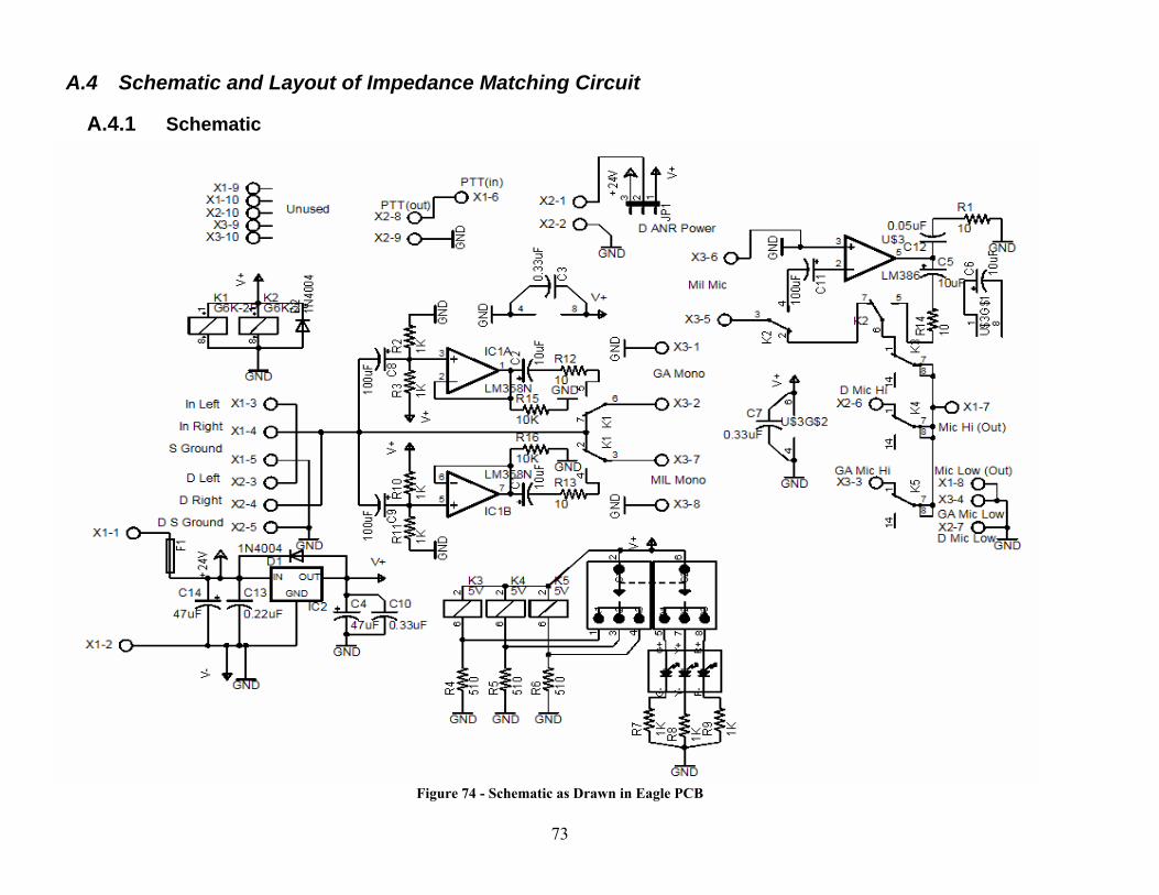
73
A.4 Schematic and Layout of Impedance Matching Circuit
A.4.1 Schematic
Figure 74 - Schematic as Drawn in Eagle PCB
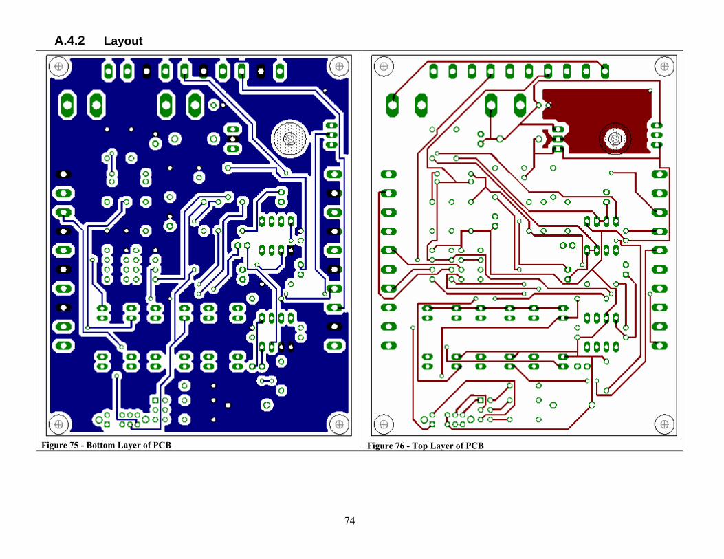
74
A.4.2 Layout
Figure 75 - Bottom Layer of PCB
Figure 76 - Top Layer of PCB
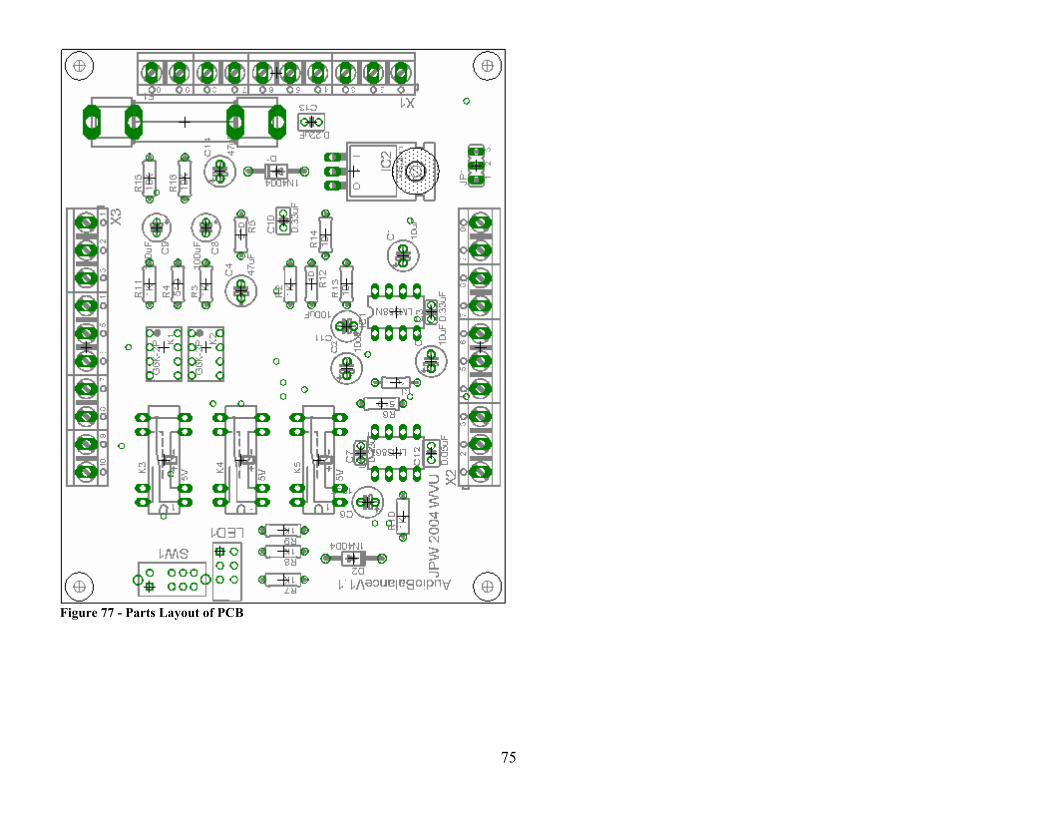
75
Figure 77 - Parts Layout of PCB
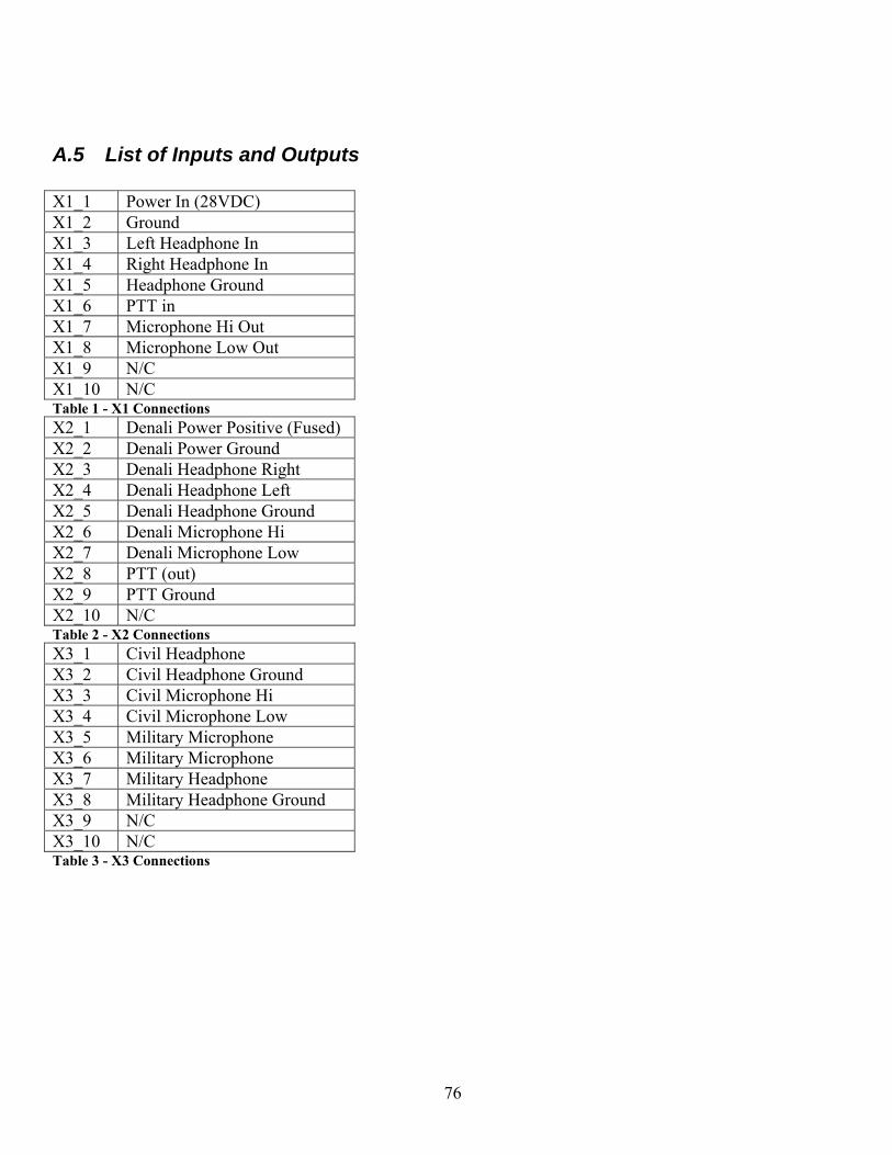
76
A.5 List of Inputs and Outputs X1_1 Power In (28VDC) X1_2 Ground X1_3 Left Headphone In X1_4 Right Headphone In X1_5 Headphone Ground X1_6 PTT in X1_7 Microphone Hi Out X1_8 Microphone Low Out X1_9 N/C X1_10 N/C Table 1 - X1 Connections X2_1 Denali Power Positive (Fused) X2_2 Denali Power Ground X2_3 Denali Headphone Right X2_4 Denali Headphone Left X2_5 Denali Headphone Ground X2_6 Denali Microphone Hi X2_7 Denali Microphone Low X2_8 PTT (out) X2_9 PTT Ground X2_10 N/C Table 2 - X2 Connections X3_1 Civil Headphone X3_2 Civil Headphone Ground X3_3 Civil Microphone Hi X3_4 Civil Microphone Low X3_5 Military Microphone X3_6 Military Microphone X3_7 Military Headphone X3_8 Military Headphone Ground X3_9 N/C X3_10 N/C Table 3 - X3 Connections
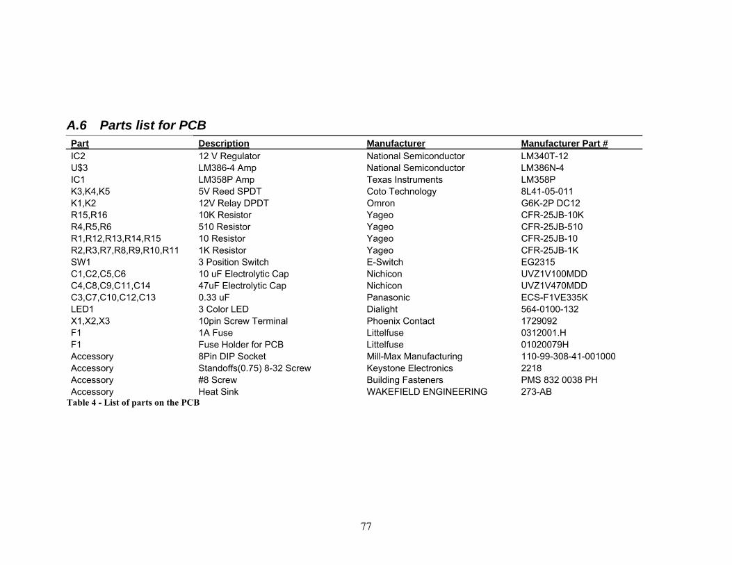
77
A.6 Parts list for PCB Part Description Manufacturer Manufacturer Part # IC2 12 V Regulator National Semiconductor LM340T-12 U$3 LM386-4 Amp National Semiconductor LM386N-4 IC1 LM358P Amp Texas Instruments LM358P K3,K4,K5 5V Reed SPDT Coto Technology 8L41-05-011 K1,K2 12V Relay DPDT Omron G6K-2P DC12 R15,R16 10K Resistor Yageo CFR-25JB-10K R4,R5,R6 510 Resistor Yageo CFR-25JB-510 R1,R12,R13,R14,R15 10 Resistor Yageo CFR-25JB-10 R2,R3,R7,R8,R9,R10,R11 1K Resistor Yageo CFR-25JB-1K SW1 3 Position Switch E-Switch EG2315 C1,C2,C5,C6 10 uF Electrolytic Cap Nichicon UVZ1V100MDD C4,C8,C9,C11,C14 47uF Electrolytic Cap Nichicon UVZ1V470MDD C3,C7,C10,C12,C13 0.33 uF Panasonic ECS-F1VE335K LED1 3 Color LED Dialight 564-0100-132 X1,X2,X3 10pin Screw Terminal Phoenix Contact 1729092 F1 1A Fuse Littelfuse 0312001.H F1 Fuse Holder for PCB Littelfuse 01020079H Accessory 8Pin DIP Socket Mill-Max Manufacturing 110-99-308-41-001000 Accessory Standoffs(0.75) 8-32 Screw Keystone Electronics 2218 Accessory #8 Screw Building Fasteners PMS 832 0038 PH Accessory Heat Sink WAKEFIELD ENGINEERING 273-AB
Table 4 - List of parts on the PCB
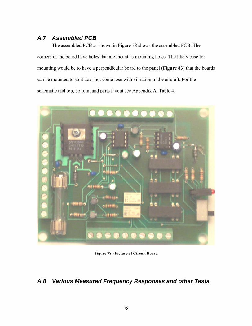
78
A.7 Assembled PCB The assembled PCB as shown in Figure 78 shows the assembled PCB. The
corners of the board have holes that are meant as mounting holes. The likely case for
mounting would be to have a perpendicular board to the panel (Figure 83) that the boards
can be mounted to so it does not come lose with vibration in the aircraft. For the
schematic and top, bottom, and parts layout see Appendix A, Table 4.
Figure 78 - Picture of Circuit Board
A.8 Various Measured Frequency Responses and other Tests
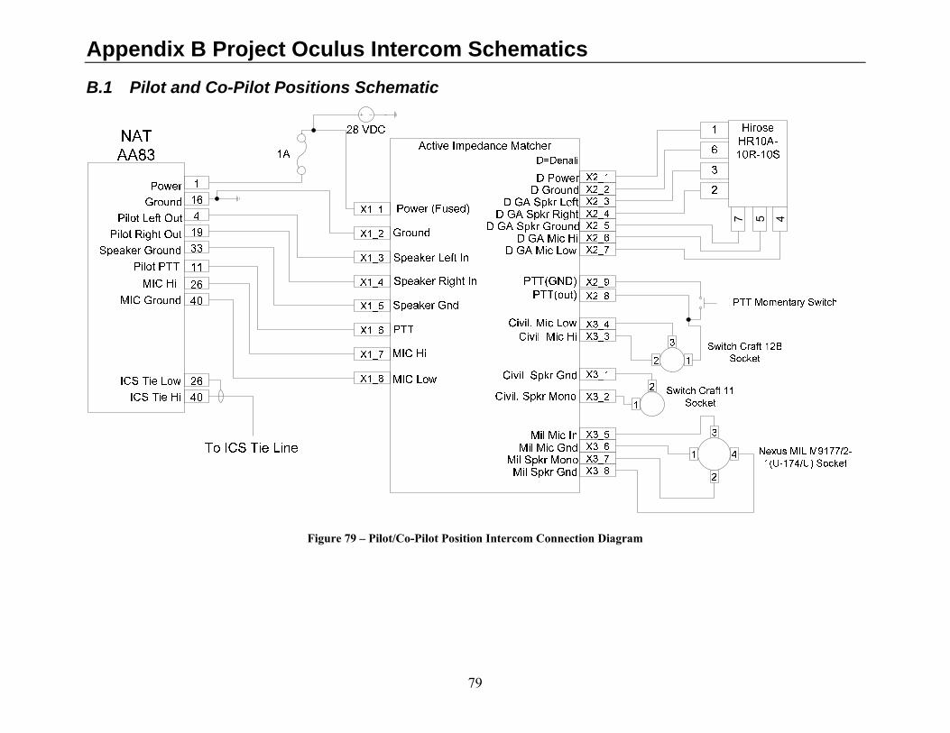
79
Appendix B Project Oculus Intercom Schematics
B.1 Pilot and Co-Pilot Positions Schematic
7 5 4
Figure 79 – Pilot/Co-Pilot Position Intercom Connection Diagram
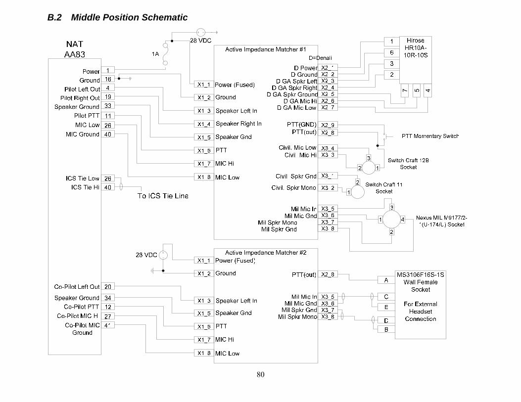
80
B.2 Middle Position Schematic
7 5 4
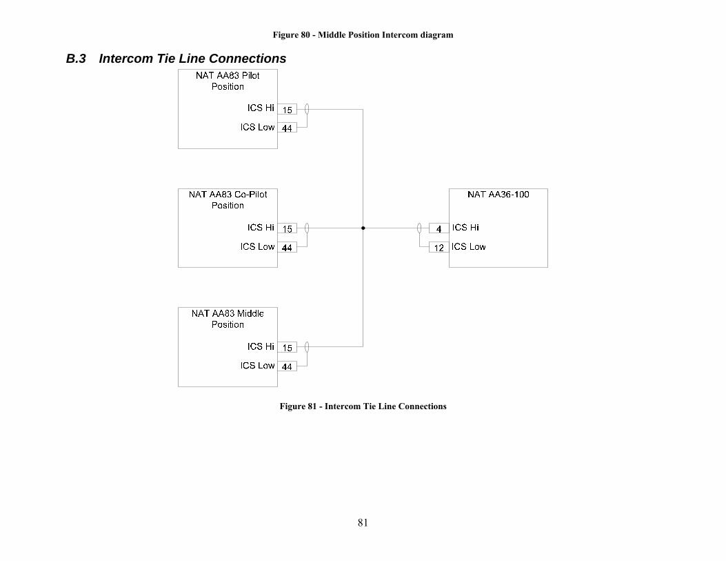
81
Figure 80 - Middle Position Intercom diagram
B.3 Intercom Tie Line Connections
Figure 81 - Intercom Tie Line Connections
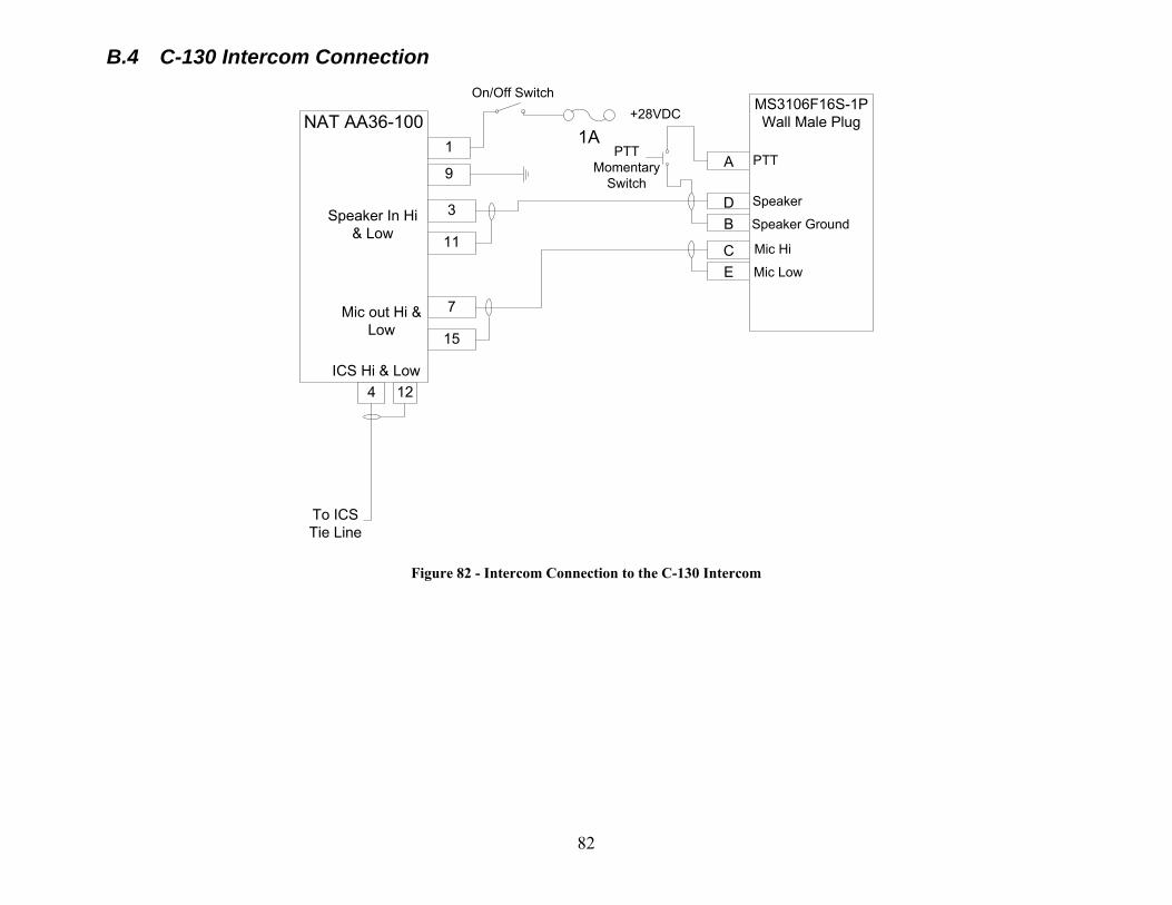
82
B.4 C-130 Intercom Connection
NAT AA36-100
3
11
7
15
4 12ICS Hi & Low
Speaker In Hi & Low
Mic out Hi & Low
1
9
+28VDC
To ICS Tie Line
MS3106F16S-1PWall Male Plug
DB
CE
APTT
Momentary Switch
On/Off Switch
PTT
Speaker
Speaker Ground
Mic Hi
Mic Low
1A
Figure 82 - Intercom Connection to the C-130 Intercom
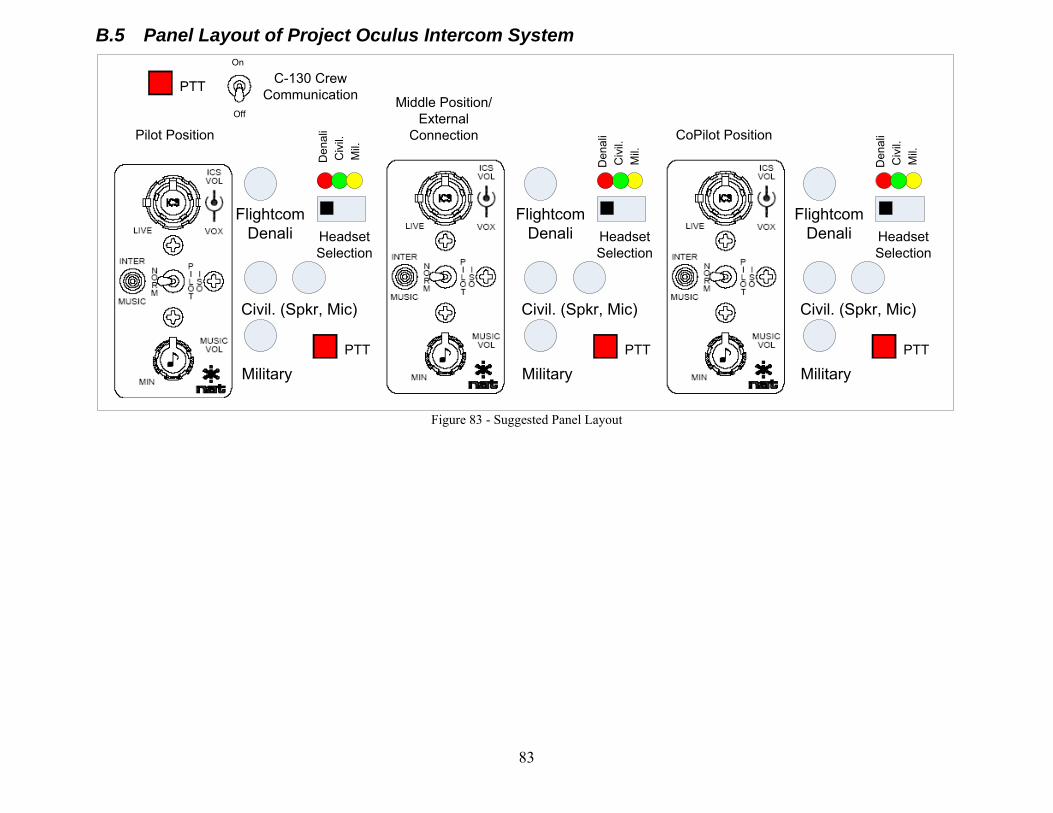
83
B.5 Panel Layout of Project Oculus Intercom System
Flightcom Denali
Civil. (Spkr, Mic)
MilitaryPTT
Headset Selection
Pilot Position
Middle Position/External
Connection CoPilot Position
Flightcom Denali
Civil. (Spkr, Mic)
MilitaryPTT
Headset Selection
Flightcom Denali
Civil. (Spkr, Mic)
MilitaryPTT
Headset Selection
C-130 Crew Communication
On
Off
Den
ali
Civ
il.M
il.
Den
ali
Civ
il.M
il.
Den
ali
Civ
il.M
il.
PTT
Figure 83 - Suggested Panel Layout
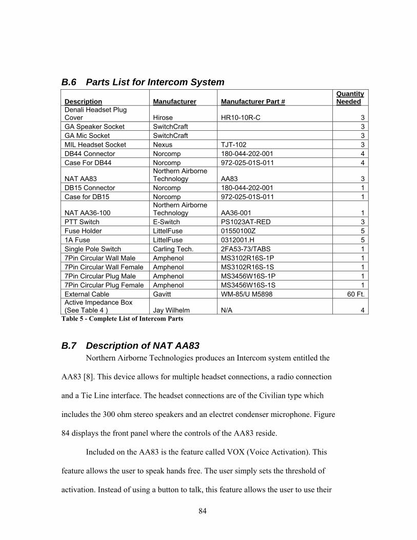
84
B.6 Parts List for Intercom System
Description Manufacturer Manufacturer Part # Quantity Needed
Denali Headset Plug Cover Hirose HR10-10R-C 3GA Speaker Socket SwitchCraft 3GA Mic Socket SwitchCraft 3MIL Headset Socket Nexus TJT-102 3DB44 Connector Norcomp 180-044-202-001 4Case For DB44 Norcomp 972-025-01S-011 4
NAT AA83 Northern Airborne Technology AA83 3
DB15 Connector Norcomp 180-044-202-001 1Case for DB15 Norcomp 972-025-01S-011 1
NAT AA36-100 Northern Airborne Technology AA36-001 1
PTT Switch E-Switch PS1023AT-RED 3Fuse Holder LittelFuse 01550100Z 51A Fuse LittelFuse 0312001.H 5Single Pole Switch Carling Tech. 2FA53-73/TABS 17Pin Circular Wall Male Amphenol MS3102R16S-1P 17Pin Circular Wall Female Amphenol MS3102R16S-1S 17Pin Circular Plug Male Amphenol MS3456W16S-1P 17Pin Circular Plug Female Amphenol MS3456W16S-1S 1External Cable Gavitt WM-85/U M5898 60 Ft.Active Impedance Box (See Table 4 ) Jay Wilhelm N/A 4
Table 5 - Complete List of Intercom Parts
B.7 Description of NAT AA83 Northern Airborne Technologies produces an Intercom system entitled the
AA83 [8]. This device allows for multiple headset connections, a radio connection
and a Tie Line interface. The headset connections are of the Civilian type which
includes the 300 ohm stereo speakers and an electret condenser microphone. Figure
84 displays the front panel where the controls of the AA83 reside.
Included on the AA83 is the feature called VOX (Voice Activation). This
feature allows the user to speak hands free. The user simply sets the threshold of
activation. Instead of using a button to talk, this feature allows the user to use their
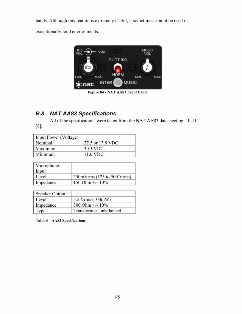
85
hands. Although this feature is extremely useful, it sometimes cannot be used in
exceptionally loud environments.
Figure 84 - NAT AA83 Front Panel
B.8 NAT AA83 Specifications All of the specifications were taken from the NAT AA83 datasheet pg. 10-11 [8]. Input Power (Voltage) Nominal 27.5 or 13.8 VDC Maximum 30.3 VDC Minimum 11.0 VDC Microphone Input
Level 250mVrms (125 to 500 Vrms) Impedance 150 Ohm +/- 10% Speaker Output Level 5.5 Vrms (100mW) Impedance 300 Ohm +/- 10% Type Transformer, unbalanced Table 6 - AA83 Specifications
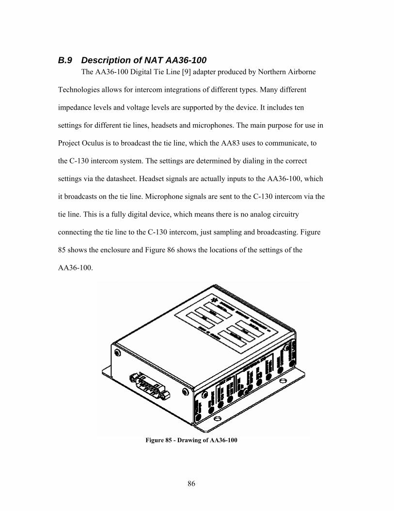
86
B.9 Description of NAT AA36-100 The AA36-100 Digital Tie Line [9] adapter produced by Northern Airborne
Technologies allows for intercom integrations of different types. Many different
impedance levels and voltage levels are supported by the device. It includes ten
settings for different tie lines, headsets and microphones. The main purpose for use in
Project Oculus is to broadcast the tie line, which the AA83 uses to communicate, to
the C-130 intercom system. The settings are determined by dialing in the correct
settings via the datasheet. Headset signals are actually inputs to the AA36-100, which
it broadcasts on the tie line. Microphone signals are sent to the C-130 intercom via the
tie line. This is a fully digital device, which means there is no analog circuitry
connecting the tie line to the C-130 intercom, just sampling and broadcasting. Figure
85 shows the enclosure and Figure 86 shows the locations of the settings of the
AA36-100.
Figure 85 - Drawing of AA36-100
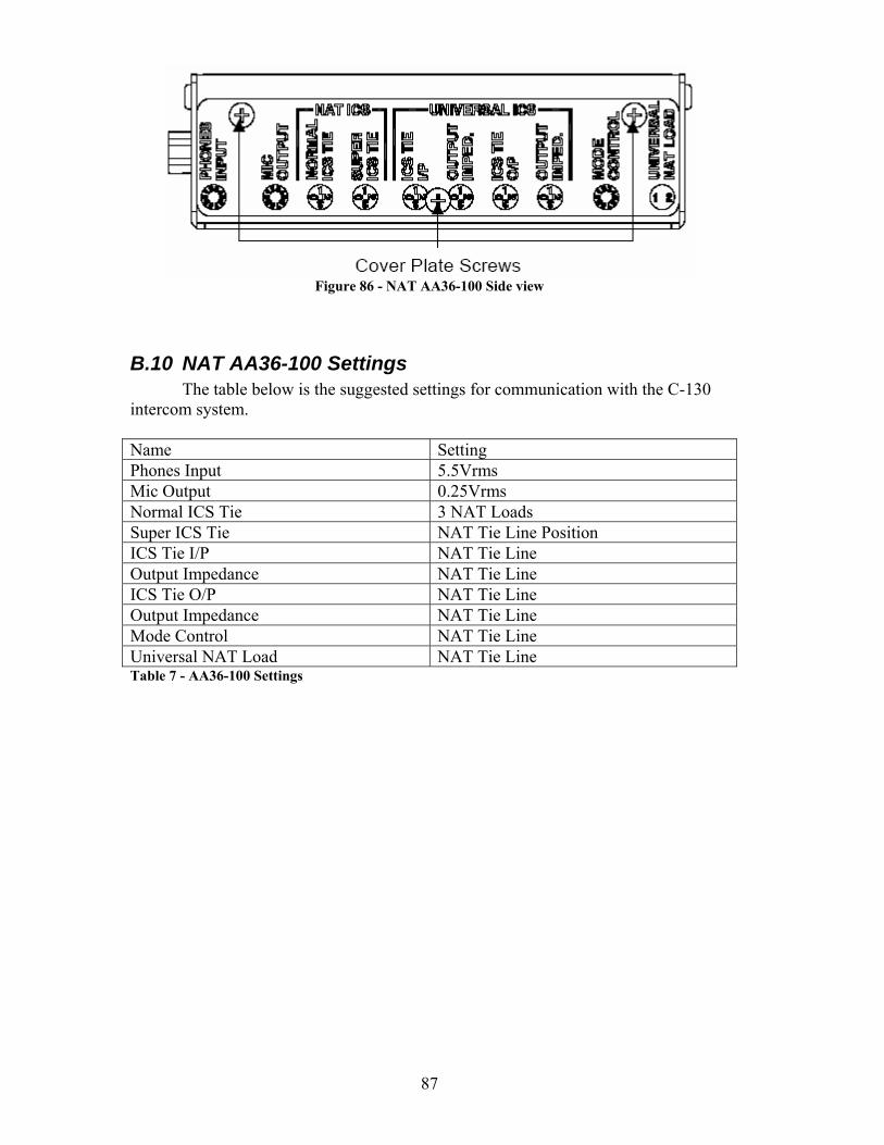
87
Figure 86 - NAT AA36-100 Side view
B.10 NAT AA36-100 Settings The table below is the suggested settings for communication with the C-130
intercom system. Name Setting Phones Input 5.5Vrms Mic Output 0.25Vrms Normal ICS Tie 3 NAT Loads Super ICS Tie NAT Tie Line Position ICS Tie I/P NAT Tie Line Output Impedance NAT Tie Line ICS Tie O/P NAT Tie Line Output Impedance NAT Tie Line Mode Control NAT Tie Line Universal NAT Load NAT Tie Line Table 7 - AA36-100 Settings
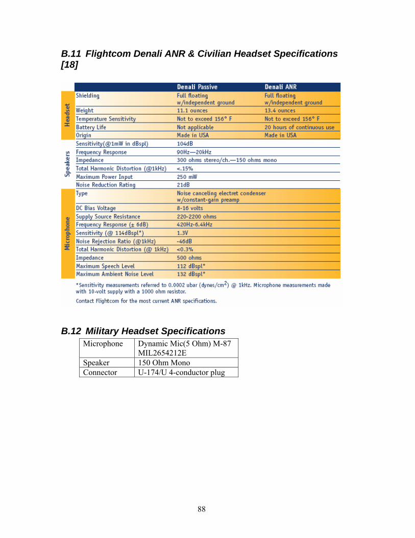
88
B.11 Flightcom Denali ANR & Civilian Headset Specifications [18]
B.12 Military Headset Specifications Microphone Dynamic Mic(5 Ohm) M-87
MIL2654212E Speaker 150 Ohm Mono Connector U-174/U 4-conductor plug
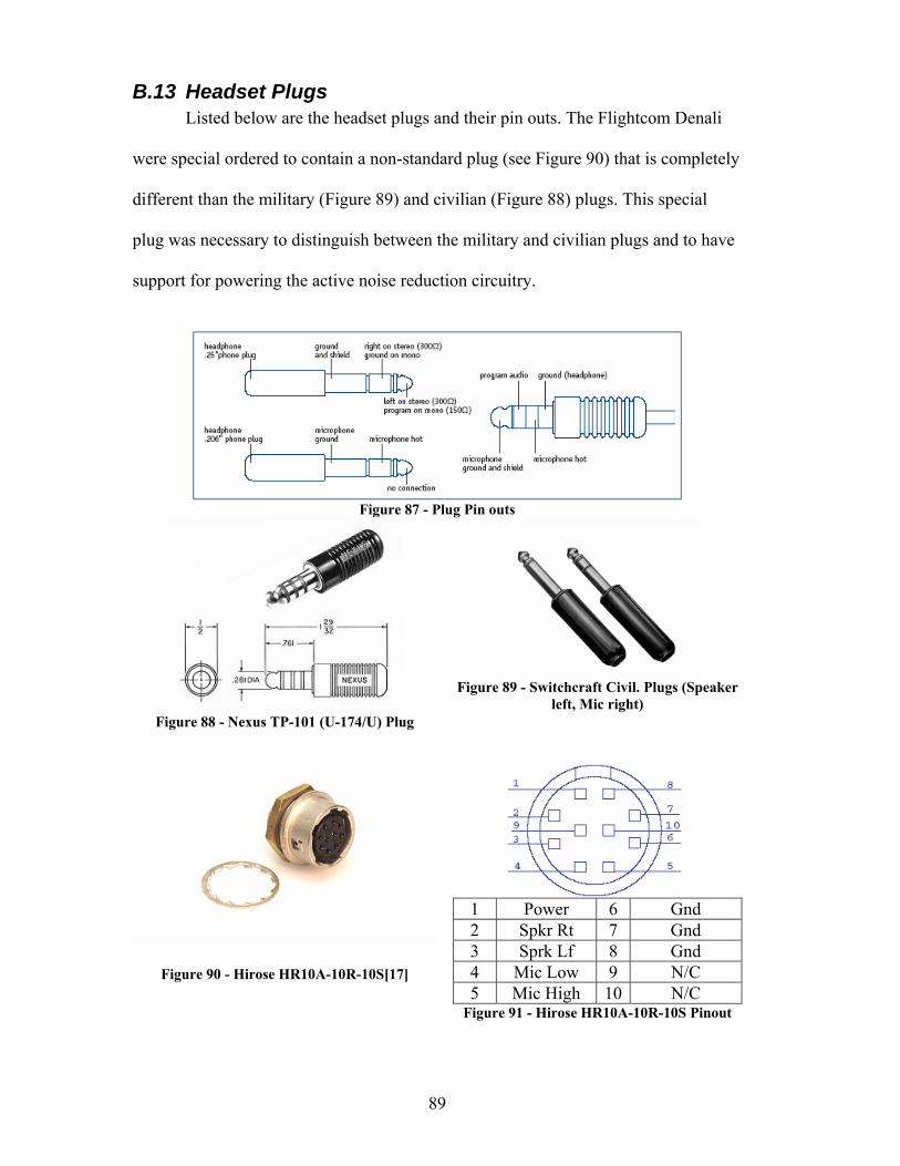
89
B.13 Headset Plugs Listed below are the headset plugs and their pin outs. The Flightcom Denali
were special ordered to contain a non-standard plug (see Figure 90) that is completely
different than the military (Figure 89) and civilian (Figure 88) plugs. This special
plug was necessary to distinguish between the military and civilian plugs and to have
support for powering the active noise reduction circuitry.
Figure 87 - Plug Pin outs
Figure 88 - Nexus TP-101 (U-174/U) Plug
Figure 89 - Switchcraft Civil. Plugs (Speaker
left, Mic right)
Figure 90 - Hirose HR10A-10R-10S[17]
1 Power 6 Gnd 2 Spkr Rt 7 Gnd 3 Sprk Lf 8 Gnd 4 Mic Low 9 N/C 5 Mic High 10 N/C
Figure 91 - Hirose HR10A-10R-10S Pinout