Embed Size (px)
Citation preview
TO 00-25-172CL-4
TECHNICAL MANUALCHECKLIST
AIRCRAFT FUEL SERVICINGWITH R-9, R-11, AND
COMMERCIAL FUEL SERVICINGTRUCKS AND WITH FUELSOPERATIONAL READINESS
CAPABILITY EQUIPMENT (FORCE)
This publication augments TO 00-25-172.
DISTRIBUTION STATEMENT A - Approved for public release; distribution is unlimited. PA CaseNumber 04-10-75. Other requests for this document shall be referred to 406 SCMS/GUEE,Robins AFB, GA 31098. Questions concerning technical content shall be referred to HQ AFMC/SE.
Published Under Authority of the Secretary of the Air Force
21 NOVEMBER 2013 CHANGE 6 - 23 OCTOBER 2015
BASIC AND ALL CHANGES HAVE BEEN MERGED TO MAKE THIS A COMPLETE PUBLICATION.
Downloaded from http://www.everyspec.com
Dates of issue for original and changed pages are:
Original . . . 0. .21 November 2013Change . . . 1 . . . 17 January 2014Change . . . 2 . . 20 February 2014Change . . . 3. . . .19 August 2014
Change . . . 4. .29 November 2014Change . . . 5. . . . .15 April 2015Change . . . 6 . . . 23 October 2015
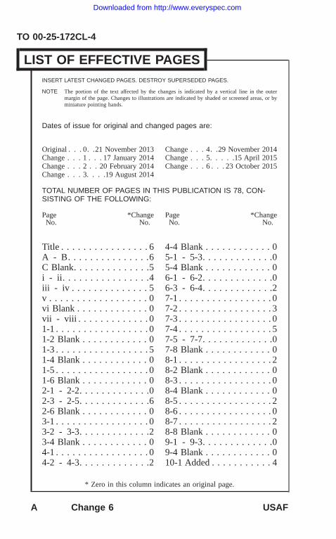
TOTAL NUMBER OF PAGES IN THIS PUBLICATION IS 78, CON-SISTING OF THE FOLLOWING:
Page *ChangeNo. No.
Page *ChangeNo. No.
Title . . . . . . . . . . . . . . . . 6A - B. . . . . . . . . . . . . . .6C Blank. . . . . . . . . . . . . .5i - ii. . . . . . . . . . . . . . . .4iii - iv . . . . . . . . . . . . . . 5v . . . . . . . . . . . . . . . . . . 0vi Blank . . . . . . . . . . . . . 0vii - viii . . . . . . . . . . . . . 01-1 . . . . . . . . . . . . . . . . . 01-2 Blank . . . . . . . . . . . . 01-3 . . . . . . . . . . . . . . . . . 51-4 Blank . . . . . . . . . . . . 01-5 . . . . . . . . . . . . . . . . . 01-6 Blank . . . . . . . . . . . . 02-1 - 2-2. . . . . . . . . . . . .02-3 - 2-5. . . . . . . . . . . . .62-6 Blank . . . . . . . . . . . . 03-1 . . . . . . . . . . . . . . . . . 03-2 - 3-3. . . . . . . . . . . . .23-4 Blank . . . . . . . . . . . . 04-1 . . . . . . . . . . . . . . . . . 04-2 - 4-3. . . . . . . . . . . . .2
4-4 Blank . . . . . . . . . . . . 05-1 - 5-3. . . . . . . . . . . . .05-4 Blank . . . . . . . . . . . . 06-1 - 6-2. . . . . . . . . . . . .06-3 - 6-4. . . . . . . . . . . . .27-1 . . . . . . . . . . . . . . . . . 07-2 . . . . . . . . . . . . . . . . . 37-3 . . . . . . . . . . . . . . . . . 07-4 . . . . . . . . . . . . . . . . . 57-5 - 7-7. . . . . . . . . . . . .07-8 Blank . . . . . . . . . . . . 08-1 . . . . . . . . . . . . . . . . . 28-2 Blank . . . . . . . . . . . . 08-3 . . . . . . . . . . . . . . . . . 08-4 Blank . . . . . . . . . . . . 08-5 . . . . . . . . . . . . . . . . . 28-6 . . . . . . . . . . . . . . . . . 08-7 . . . . . . . . . . . . . . . . . 28-8 Blank . . . . . . . . . . . . 09-1 - 9-3. . . . . . . . . . . . .09-4 Blank . . . . . . . . . . . . 010-1 Added . . . . . . . . . . . 4
TO 00-25-172CL-4
LIST OF EFFECTIVE PAGESINSERT LATEST CHANGED PAGES. DESTROY SUPERSEDED PAGES.
NOTE The portion of the text affected by the changes is indicated by a vertical line in the outermargin of the page. Changes to illustrations are indicated by shaded or screened areas, or byminiature pointing hands.
* Zero in this column indicates an original page.
A Change 6 USAF
Downloaded from http://www.everyspec.com
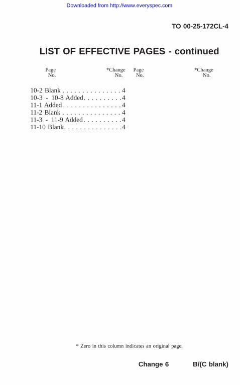
10-2 Blank . . . . . . . . . . . . . . . 410-3 - 10-8 Added. . . . . . . . . .411-1 Added . . . . . . . . . . . . . . . 411-2 Blank . . . . . . . . . . . . . . . 411-3 - 11-9 Added . . . . . . . . . . 411-10 Blank. . . . . . . . . . . . . . .4
TO 00-25-172CL-4
LIST OF EFFECTIVE PAGES - continued
Page *ChangeNo. No.
Page *ChangeNo. No.
* Zero in this column indicates an original page.
Change 6 B/(C blank)
Downloaded from http://www.everyspec.com

Downloaded from http://www.everyspec.com
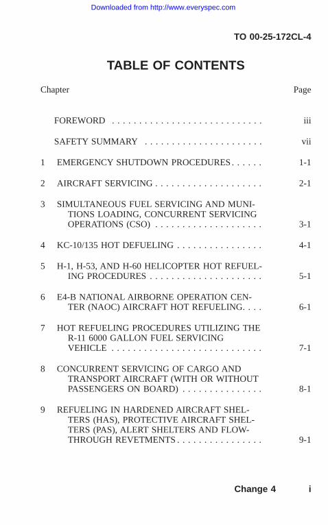
TABLE OF CONTENTS
Chapter Page
FOREWORD . . . . . . . . . . . . . . . . . . . . . . . . . . . . iii
SAFETY SUMMARY . . . . . . . . . . . . . . . . . . . . . . vii
1 EMERGENCY SHUTDOWN PROCEDURES . . . . . . 1-1
2 AIRCRAFT SERVICING . . . . . . . . . . . . . . . . . . . . 2-1
3 SIMULTANEOUS FUEL SERVICING AND MUNI-TIONS LOADING, CONCURRENT SERVICINGOPERATIONS (CSO) . . . . . . . . . . . . . . . . . . . . 3-1
4 KC-10/135 HOT DEFUELING . . . . . . . . . . . . . . . . 4-1
5 H-1, H-53, AND H-60 HELICOPTER HOT REFUEL-ING PROCEDURES . . . . . . . . . . . . . . . . . . . . . 5-1
6 E4-B NATIONAL AIRBORNE OPERATION CEN-TER (NAOC) AIRCRAFT HOT REFUELING. . . . 6-1
7 HOT REFUELING PROCEDURES UTILIZING THER-11 6000 GALLON FUEL SERVICINGVEHICLE . . . . . . . . . . . . . . . . . . . . . . . . . . . . 7-1
8 CONCURRENT SERVICING OF CARGO ANDTRANSPORT AIRCRAFT (WITH OR WITHOUTPASSENGERS ON BOARD) . . . . . . . . . . . . . . . 8-1
9 REFUELING IN HARDENED AIRCRAFT SHEL-TERS (HAS), PROTECTIVE AIRCRAFT SHEL-TERS (PAS), ALERT SHELTERS AND FLOW-THROUGH REVETMENTS . . . . . . . . . . . . . . . . 9-1
TO 00-25-172CL-4
Change 4 i
Downloaded from http://www.everyspec.com
Chapter Page
10 HOT REFUELING PROCEDURES UTILIZING FU-ELS OPERATIONAL READINESS CAPABILITYEQUIPMENT (FORCE) . . . . . . . . . . . . . . . . . . . 10-1
11 AIRCRAFT SERVICING WITH FUELS OPERA-TIONAL READINESS CAPABILITY EQUIP-MENT (FORCE) . . . . . . . . . . . . . . . . . . . . . . . . 11-1
TO 00-25-172CL-4
TABLE OF CONTENTS - CONTINUED
ii Change 4
Downloaded from http://www.everyspec.com
FOREWORD
1 PURPOSE.
This checklist is a step by step guide in abbreviated form for use as areference to ensure accomplishment of selected tasks by a predeterminedsequence procedure. The intent of this checklist is to eliminate the prob-ability of omission of a step in accomplishment of the intended task. Theprocedures contained herein are presented for use by qualified personneland are not intended to provide full technical instructions.
2 SCOPE.
This checklist provides sequenced procedures for servicing aircraft usingUSAF fuel servicing vehicles and commercial fuel servicing trucks de-signed to the requirements of the National Fire Protection Association(NFPA) Standard 407. These instructions will be used by refueling unitoperators as an aid to safe and efficient aircraft servicing.
3 ABBREVIATIONS.
All abbreviations used in this manual are in accordance with ASMEY14.38, Abbreviations and Acronyms for Use on Drawings and RelatedDocuments.
AF Air ForceAFTO Air Force Technical OrderCSO Concurrent Servicing OperationsCSS Chief Servicing SupervisorDoD Department of DefenseFCC Fuels Control Centerft FeetGPM Gallons Per MinuteHAS Hardened Aircraft Shelterslb PoundNAOC National Airborne Operation CenterNFPA National Fire Protection AssociationPAS Protective Aircraft Shelters
TO 00-25-172CL-4
Change 5 iii
Downloaded from http://www.everyspec.com
PSI Pounds Per Square Inch
4 RELATED PUBLICATIONS.
The following publications contain information in support of this techni-cal manual.
List of Related Publications
Number TitleASME Y14.38 Abbreviations and Acronyms for Use on
Drawings and Related DocumentsTO 00-5-1-WA-1 Air Force Technical Order SystemTO 00-25-172 Ground Servicing of Aircraft and Static
Grounding/BondingTO 00-25-195-WA-1 Source, Maintenance, and Recoverability
Coding of Air Force Weapons, Systems,and Equipment
TO 00-25-234-WA-1 General Shop Practice Requirements forthe Repair, Maintenance, and Test ofElectrical Equipment
5 RECORD OF APPLICABLE TIME COMPLIANCE TECHNICALORDERS (TCTOs).
List of Time Compliance Technical Orders
TCTONumber
TCTOTitle
TCTODate
None
TO 00-25-172CL-4
iv Change 5
Downloaded from http://www.everyspec.com
6 HARDNESS CRITICAL ITEMS (HCI).
The HCI symbol ( ) establishes special requirements lim-iting changes and substitutions and that the specific parts listedmust be used to ensure hardness is not degraded.
If included, items with nuclear survivability requirements are markedwith the HCI symbol ( ). All changes to, or proposed substitutions of,HCIs must be approved by the acquiring activity.
7 ELECTROSTATIC DISCHARGE SENSITIVE (ESDS)ITEMS.
All ESDS parts shall be handled in accordance with the ESDSdevice handling procedures in TO 00-25-234-WA-1.
If included, items containing ESDS parts are marked with the ESDSsymbol ( ).
8 CHANGE RECOMMENDATIONS.
Recommendations proposing changes to this technical order shall be sub-mitted on an AFTO Form 22 in accordance with TO 00-5-1-WA-1. For-ward completed AFTO Form 22 to the Technical Order ManagementAgency (TOMA) at: [email protected].
TO 00-25-172CL-4
v/(vi blank)
Downloaded from http://www.everyspec.com

Downloaded from http://www.everyspec.com
SAFETY SUMMARY
1 GENERAL SAFETY INSTRUCTIONS.
This manual describes physical and/or chemical processes which maycause injury or death to personnel, or damage to equipment, if not prop-erly followed. This safety summary includes general safety precautionsand instructions that must be understood and applied during operationand maintenance to ensure personnel safety and protection of equipment.Prior to performing any specific task, the WARNINGs, CAUTIONs, andNOTEs included in that task shall be reviewed and understood.
2 WARNINGS, CAUTIONS, AND NOTES.
WARNINGs and CAUTIONs are used in this manual to highlight oper-ating or maintenance procedures, practices, conditions, or statementswhich are considered essential to protection of personnel (WARNING) orequipment (CAUTION). WARNINGs and CAUTIONs immediately pre-cede the step or procedure to which they apply. WARNINGs and CAU-TIONs consist of four parts: heading (WARNING, CAUTION, or icon),a statement of the hazard, minimum precautions, and possible results ifdisregarded. NOTEs are used in this manual to highlight operating ormaintenance procedures, practices, conditions, or statements which arenot essential to protection of personnel or equipment. NOTEs may pre-cede or follow the step or procedure, depending upon the information tobe highlighted. The headings used and their definitions are as follows:
Highlights an essential operating or maintenance procedure,practice, condition, statement, etc., which if not strictly ob-served, could result in injury to, or death of, personnel or longterm health hazards.
TO 00-25-172CL-4
vii
Downloaded from http://www.everyspec.com
Highlights an essential operating or maintenance procedure,practice, condition, statement, etc., which if not strictly ob-served, could result in damage to, or destruction of, equipmentor loss of mission effectiveness.
NOTE
Highlights an essential operating or maintenance procedure,condition, or statement.
TO 00-25-172CL-4
viii
Downloaded from http://www.everyspec.com
CHAPTER 1EMERGENCY SHUTDOWN PROCEDURES
INTRODUCTION.
This checklist is a step by step guide in abbreviated form for use as areference to ensure accomplishment of selected tasks by a predeterminedsequence procedure. The intent of this checklist is to eliminate the prob-ability of omission of a step in accomplishment of the intended task. Theprocedures contained herein are presented for use by qualified personneland are not intended to provide full technical instructions. This checklistprovides sequenced procedures for servicing aircraft using USAF fuelservicing vehicles and commercial fuel servicing trucks designed to therequirements of the National Fire Protection Association (NFPA) Stan-dard 407. These instructions will be used by refueling unit operators asan aid to safe and efficient aircraft servicing.
TO 00-25-172CL-4
1-1/(1-2 blank)
Downloaded from http://www.everyspec.com

Downloaded from http://www.everyspec.com
EMERGENCY SHUTDOWN PROCEDURES.
During aircraft servicing, the refueling unit operator will monitor therefueler for fuel leaks, ignition sources and other indications of a possiblemalfunction. In the event of an emergency, shutdown the unit as follows:
a. Release deadman control.
b. Push engine auxiliary throttle control all the way in.
c. Turn off emergency switch.
d. Close hose reel shut off valve.
e. Close main tank emergency shut off valve.
f. Notify aircraft servicing supervisor, operations expediter and FuelsControl Center (FCC), if possible.
g. Evacuate area if instructed by servicing supervisor or fire depart-ment personnel.
NOTE
In case of fuel spill other than normal aircraft venting, do notevacuate fuel servicing vehicle until area is declared safe byfire department personnel.
TO 00-25-172CL-4
Change 5 1-3/(1-4 blank)
Downloaded from http://www.everyspec.com

Downloaded from http://www.everyspec.com
HAND SIGNALS.
a. OK or Transfer Fuel: Hand raised thumb up.
b. Negative or Malfunction or Not Clear: Hand raised thumb down.
c. Stop or Cut Engine/Power: Movement of either hand acrossthroat.
TO 00-25-172CL-4
1-5/(1-6 blank)
Downloaded from http://www.everyspec.com

Downloaded from http://www.everyspec.com
CHAPTER 2AIRCRAFT SERVICING
GENERAL PROCEDURES.
a. Stop 25 or more feet from aircraft.
b. Approach upon direction of servicing crew member.
c. Ensure servicing crew member prepositions wheel chock and usesa spotter when backing toward aircraft and keeps sight of spotter inmirror prior to and during backing operation.
d. Position vehicle for servicing.
e. Set parking brake, transmission and PTO as required.
f. Shut off radio, if defueling. (Intrinsically safe radios can remainon.)
g. Chock the unit.
h. Bond fuel servicing vehicle to aircraft.
i. Unlock control panel and clear meters, if applicable.
j. Get verification of proper fuel grade, if applicable.
NOTE
Meter rotation with the hose reel valves closed and the selectorlever in any mode other than DEFUEL or EVACUATION, in-dicates a defective defuel control valve. This condition must bereported immediately and the refueler withdrawn from serviceuntil the condition is corrected.
TO 00-25-172CL-4
2-1
Downloaded from http://www.everyspec.com
If movement of the vehicle is indicated when the auxiliarythrottle is pulled out, shut down unit by pushing the throttle“in” and placing the emergency switch to “OFF” position.
k. Prepare vehicle for appropriate servicing operation.
TO 00-25-172CL-4
2-2
Downloaded from http://www.everyspec.com
• Servicing crew member shall use no more than one aircrafttransfer/booster pump, not to exceed 175 GPM when defu-eling aircraft with Kovatch R-11 and Oshkosh R-11 fuelservicing vehicles. Failure to follow this guidance may re-sult in overfilling the vehicle’s cargo tank.
• Refueling operators shall ensure the Defuel Override Con-trol Valve is in the OFF position and locked (Oshkosh R-11)and the Red Protective Cover is closed (1st and 2nd genera-tion Kovatch R-11) prior to starting any fuel operations.Failure to do so could result in a fuel spill.
• During multiple source refueling, operators must continu-ously monitor refueling flow meters for correct indication offuel flow. If backflow is detected, immediately stop all refu-eling operations. In addition, if using 1st or 2nd generationKovatch R-11s, operator must monitor the tank wet/dry sen-sor indicator lights on the main control panel. If the wet(RED) indicator light illuminates during operation, the op-erator will immediately stop refuel (releasing deadman).
• When multiple refueling trucks are located on the same sideor wing of an aircraft, the vehicles must be positioned at theaircraft prior to initiating any fuel flow and remain posi-tioned and bonded until fuel flow is terminated on all truckson that side of the aircraft.
• During defueling with Condiesel (1981) R-9, Kovatch R-9,and Oshkosh R-11 fuel servicing vehicles, verify via pre-check/pretest that the high level shutoff is operational. Thisis accomplished by using the Defuel High Level Pretest but-ton on the main control panel. For Kovatch R-11 fuel ser-vicing vehicles equipped with the electronically controlledhigh level shutoff system, observe the cargo tank sensorgreen light on the main control panel is illuminated prior to
TO 00-25-172CL-4
Change 6 2-3
Downloaded from http://www.everyspec.com
initiating the operation.
• Refueling Operator shall ensure nozzles equipped ballstrainer valves are in the correct refuel/defuel position. Theball valve strainer must be inspected and cleaned as requiredevery time the ball valve position is switched from the re-fuel to defuel or defuel to refuel position. This strainer is thelast line of protection for preventing solid contaminates fromentering AC or the refueling vehicle components. If thestrainer is not inspected and cleaned if required, damage toAC fuel systems/refueling vehicle components and fuelspills may occur.
NOTE
Defueling in the evacuation mode is not permitted because thefuel is not filtered.
l. Extend hose and, if equipped with a ball strainer, ensure valve is inthe correct refuel/defuel position. Ensure the servicing crew mem-ber connects the SPR nozzle to the aircraft and if equipped with astrainer coupling quick disconnect, prior to pressuring the hose,servicing crew member must test the strainer coupling quick dis-connect locking device for positive engagement.
m. Test nozzle to be certain the single point servicing nozzle cannot beremoved from aircraft when valve handle is in the open and lockedposition.
n. Begin pumping operation upon direction of the servicing crewmember. Fuels servicing equipment operator activates deadmancontrol valve during fuel transfer.
o. Closely monitor control panel during operation.
TO 00-25-172CL-4
2-4 Change 6
Downloaded from http://www.everyspec.com
The pump will cavitate when the fuel level in the tank is re-duced to approximately 500 gallons. Attempting to pump fuelbeyond this point will eliminate the pump prime, prevent hoseevacuation and may result in overheating/damage of the pumpseal. Shut down the pump immediately when the pump tempoincreases indicating a loss of pump prime.
p. Record differential pressure reading if required.
q. Upon completion of fuel servicing operation, stow fuel servicinghoses, bonding wires, and deadman control.
r. Complete accounting forms, ensure identaplate is returned to ser-vicing crew member, and obtain signature.
s. Perform walkaround inspection, stow wheel chock and depart area.
TO 00-25-172CL-4
Change 6 2-5/(2-6 blank)
Downloaded from http://www.everyspec.com

Downloaded from http://www.everyspec.com
CHAPTER 3SIMULTANEOUS FUEL SERVICING ANDMUNITIONS LOADING, CONCURRENT
SERVICING OPERATIONS (CSO)
INTRODUCTION.
This checklist is a step-by-step guide in abbreviated form for use as areference to ensure accomplishment of selected tasks by a predeterminedsequence procedure. The intent of this checklist is to eliminate the prob-ability of omission of a step in the accomplishment of CSO. The proce-dures contained herein are presented for use by qualified personnel andare not intended to provide full technical instructions. CSO-qualified fu-els specialists will have a thorough working knowledge of these precau-tions, making it unnecessary for a check off of each step.
a. This procedure will be utilized to conduct cold refueling and simul-taneous munitions loading.
b. Refuelers when equipped with deadman controls are authorized foruse in CSO operations.
c. Perform a pressurized serviceability check of the refueling equip-ment once every 24 hours or when returned to service after main-tenance.
AIRCRAFT SERVICING.
a. Unless prepositioned, stop 25 feet or more from aircraft and thenapproach only upon direction from servicing crew member.
b. Position vehicle for servicing operation; have servicing crew mem-ber place wheel chocks; maintain at least a minimum 10-foot dis-tance between refueling unit and aircraft.
c. Set parking brake, transmission and PTO, as required.
d. Bond fuel servicing vehicle to aircraft.
TO 00-25-172CL-4
3-1
Downloaded from http://www.everyspec.com
e. Unlock control panel and clear meters, if applicable.
f. Get verification of proper fuel grade, if applicable.
Do not change selector valve from one mode or operation toanother without returning engine throttle to idle speed.
g. Prepare vehicle for servicing operation.
h. Fuel Servicing Equipment Operator will operate deadman controlvalve during fuel transfer.
Refueling Operator shall ensure nozzles equipped ball strainervalves are in the correct refuel/defuel position. The ball valvestrainer must be inspected and cleaned as required every timethe ball valve position is switched from the refuel to defuel ordefuel to refuel position. This strainer is the last line of protec-tion for preventing solid contaminates from entering AC or therefueling vehicle components. If the strainer is not inspectedand cleaned if required, damage to AC fuel systems/refuelingvehicle components and fuel spills may occur.
NOTE
The refueling unit operator will be provided with an intercomheadset to enable monitoring of the intercom conversation toexpedite rapid shutdown of the refueling unit in the event of anemergency. (NUCLEAR ONLY)
i. Extend hose and if equipped with a ball strainer, ensure valve is inthe correct refuel/defuel position. Ensure the servicing crew mem-ber connects the SPR nozzle to the aircraft and if equipped with astrainer coupling quick disconnect, prior to pressuring the hose,servicing crew member must test the strainer coupling quick dis-connect locking device for positive engagement.
TO 00-25-172CL-4
3-2 Change 2
Downloaded from http://www.everyspec.com
j. Test nozzle to be certain the single point servicing nozzle cannot beremoved from aircraft when valve handle is in the open and lockedposition.
k. Begin pumping operation upon direction of the servicing crewmember.
Be ready to push auxiliary throttle in and shut off emergencyswitch if any vehicle movement is noted or an unsafe conditionor situation develops.
l. During refueling, monitor control panel, aircraft fuel vent outlets,and aircraft servicing supervisor signals; be prepared to shut downequipment in case of leak or other malfunction.
m. Stow fuel servicing equipment and bonding wires after refueling iscompleted.
n. Complete paper work and obtain signature of servicing crew mem-ber on AF Form 1994 after aircraft departs; lock control panel, ifapplicable.
o. Perform walkaround inspection, stow wheel chock and depart area.
TO 00-25-172CL-4
Change 2 3-3/(3-4 blank)
Downloaded from http://www.everyspec.com

Downloaded from http://www.everyspec.com
CHAPTER 4KC-10/135 HOT DEFUELING
INTRODUCTION.
When performing hot defueling, all members of the fueling team exceptfire guard will be in contact with each other via the intercom system. Thisincludes the fuel truck operator. Tasks designated by an asterisk (*) willbe performed by the fuel servicing equipment operator (2F0X1) and allother tasks will be performed by a servicing crew member. It cannot beoveremphasized that these procedures must be followed in the propersequence to ensure a safe operation. These procedures are applicable onlyto fuel servicing vehicles that have operable automatic high-level cutoffs.Hot Defueling of JP-4 into fuel servicing vehicles is authorized onlyunder emergency conditions or combat situations and is not permitted fornormal day-to-day operations.
AIRCRAFT SERVICING.
NOTE
Due to the fire hazards associated with hot defueling opera-tions, the preferred distance between aircraft wingtips is 50feet. However, at those installations where aircraft parkingspace is limited, therefore not permitting a 50 foot wing tipclearance, the wing tip separation distance can be reduced to aminimum of 35 feet. Whenever a distance of less than 50 feetis maintained between aircraft, wing tips a crash fire rescuevehicle must be at the aircraft during hot defueling operations.
a. *Stop 25 or more feet from aircraft.
b. *Approach upon direction of servicing crew member.
c. Preposition wheel chock and use a spotter when backing towardaircraft.
d. *Position vehicle for servicing.
e. *Set parking brake, transmission and PTO as required.
TO 00-25-172CL-4
4-1
Downloaded from http://www.everyspec.com
f. *Shut off radio, if defueling.
g. Chock the unit.
h. Bond fuel servicing vehicle to aircraft.
i. *Get verification of proper fuel grade, if applicable.
Refueling Operator shall ensure nozzles equipped ball strainervalves are in the correct refuel/defuel position. The ball valvestrainer must be inspected and cleaned as required every timethe ball valve position is switched from the refuel to defuel ordefuel to refuel position. This strainer is the last line of protec-tion for preventing solid contaminates from entering AC or therefueling vehicle components. If the strainer is not inspectedand cleaned if required, damage to AC fuel systems/refuelingvehicle components and fuel spills may occur.
j. *Fuels servicing equipment operator will connect defueling hose tobottom loader. If hose is equipped with a ball strainer, ensure valveis in the correct refuel/defuel position. If hose is equipped with astrainer coupling quick disconnect, prior to pressuring the hose,fuels servicing equipment operator must test the strainer couplingquick disconnect locking device for positive engagement. Open ve-hicle loading and vent valves. Leave single point nozzle valveclosed.
k. Test nozzle to be certain the single point servicing nozzle cannot beremoved from aircraft when valve handle is in the open and lockedposition.
l. Ensure the servicing crew member connects the SPR nozzle to theaircraft. If hose is equipped with a ball strainer, ensure valve is inthe correct refuel/defuel position. If hose is equipped with a strainercoupling quick disconnect, prior to pressuring the hose, servicingcrew member must test the strainer coupling quick disconnect lock-ing device for positive engagement.
TO 00-25-172CL-4
4-2 Change 2
Downloaded from http://www.everyspec.com
m. *Perform intercom check with aircraft servicing supervisor and allmembers of the fuel servicing team.
n. Start aircraft engine farthest removed from the fuel servicing ve-hicle (Number 1 or 4 engine.)
o. Open SPR nozzle(s) on the aircraft.
p. *Open SPR nozzle on bottom loader.
q. Start aircraft aerial refueling off-load pumps.
r. *After fuel flow begins from aircraft, coordinate with servicingcrew member and perform a bottom loading automatic shut-offvalve check.
If shut-off valve is inoperative, terminate the operation imme-diately. Personnel are not authorized on top of the fuel servic-ing vehicle during hot defueling.
s. Complete the operation.
t. *Stow defueling hose.
u. *Obtain required signatures, perform walkaround inspection, stowwheel chock and depart area.
EMERGENCY PROCEDURE.
In the event of a fire and/or fuel spillage within the hot defueling area,immediately cease operations and evacuate the area.
TO 00-25-172CL-4
Change 2 4-3/(4-4 blank)
Downloaded from http://www.everyspec.com

Downloaded from http://www.everyspec.com
CHAPTER 5H-1, H-53, AND H-60 HELICOPTER HOT
REFUELING PROCEDURES
INTRODUCTION.
This chapter is a step-by-step guide in abbreviated form for use as areference to ensure accomplishment of selected tasks by a predeterminedsequence procedure. The intent of this chapter is to eliminate the prob-ability of omission of a step in the accomplishment of helicopter hotrefueling. The procedures contained herein are presented for use by a2F0X1 fuels specialist who is certified to hot refuel aircraft in accordancewith TO 00-25-172 and MAJCOM directives. This checklist does notprovide detailed technical instructions.
a. This procedure will be utilized to conduct hot refueling of H-1,H-53, and H-60 helicopters.
b. Refer to TO 00-25-172, Table 5-2 for approved/authorized singlepoint refueling (SPR) nozzles.
c. Perform a pressurized serviceability check of the refueling equip-ment once every 24 hours or when returned to service after main-tenance.
AIRCRAFT SERVICING.
a. Stop 50 ft or more from aircraft and then approach only upon di-rection from the servicing crew member. Maintain 25-foot mini-mum separation from any part of the aircraft.
b. Position vehicle for servicing operation; place wheel chock; main-tain maximum distance between refueling unit and aircraft.
c. Set parking brake, transmission and PTO.
d. Secure line badge, headgear and loose items inside pocket.
e. Ensure that servicing crew member bonds vehicle to aircraft.
TO 00-25-172CL-4
5-1
Downloaded from http://www.everyspec.com
f. Unlock control panel and clear meters, if applicable.
g. Get verification of proper fuel grade, if applicable.
h. Prepare vehicle for refueling.
• Do not change selector valve from one mode or operation toanother without returning engine throttle to idle speed.
• Refueling Operator shall ensure nozzles equipped ballstrainer valves are in the correct refuel/defuel position. Theball valve strainer must be inspected and cleaned as requiredevery time the ball valve position is switched from the re-fuel to defuel or defuel to refuel position. This strainer is thelast line of protection for preventing solid contaminates fromentering AC or the refueling vehicle components. If thestrainer is not inspected and cleaned if required, damage toAC fuel systems/refueling vehicle components and fuelspills may occur.
i. Extend hose and, if equipped with a ball strainer, ensure valve is inthe correct refuel/defuel position. Ensure the servicing crew mem-ber connects the SPR nozzle to the aircraft and if equipped with astrainer coupling quick disconnect, prior to pressuring the hose,servicing crew member must test the strainer coupling quick dis-connect locking device for positive engagement.
j. Test nozzle to be certain the single point servicing nozzle or closedcircuit refueling nozzle cannot be removed from aircraft when valvehandle is in the open and locked position.
k. Aircraft servicing supervisor will advise refueling equipment op-erator of fuel flow pressure restrictions. Aircraft servicing supervi-sor will operate the deadman control valve during fuel transfer.
TO 00-25-172CL-4
5-2
Downloaded from http://www.everyspec.com
l. Begin pumping operation upon direction of the servicing crewmember by actuating throttle to increase engine RPM. Pressure willnot exceed 25 PSI when hot refueling H-1 and H-60 helicoptersunless a pantograph or API 1529 hard hose is used.
To prevent injury to personnel or damage to equipment, beready to push auxiliary throttle in and shut off emergencyswitch if any vehicle movement is noted or an unsafe conditionor situation develops.
m. During refueling, monitor control panel and aircraft servicing su-pervisor signals; be prepared to shut down equipment in case ofleak or other malfunction; remove equipment from servicing areaimmediately after refueling is complete or for repair if safe to doso.
n. Complete paperwork and obtain signature of servicing crew mem-ber on AF Form 1994 after aircraft departs; lock control panel, ifapplicable.
o. Perform walkaround inspection, stow wheel chock and depart area.
TO 00-25-172CL-4
5-3/(5-4 blank)
Downloaded from http://www.everyspec.com

Downloaded from http://www.everyspec.com
CHAPTER 6E4-B NATIONAL AIRBORNE OPERATION
CENTER (NAOC) AIRCRAFT HOTREFUELING
INTRODUCTION.
This chapter is a step-by-step guide in abbreviated form for use as areference to ensure accomplishment of selected tasks by a predeterminedsequence procedure. The intent of this chapter is to eliminate the possi-bility of omission of a step in the accomplishment of NAOC (E4-B) HotRefueling. The procedures contained herein are presented for use byqualified personnel and are not intended to provide all technical instruc-tions. Qualified E4-B hot refueling specialists will have a thorough work-ing knowledge of these precautions, making it unnecessary to check offeach completed step.
NOTE
• R5/R9/R-11 fuel servicing vehicles with deadman controlswill be used for this operation.
• Waiver authority to fuel service without deadman controlsmay be issued on case-by-case basis by MAJCOM/DO/LG.
• A fuel equipment operator will be positioned at the fuelservicing vehicle and will be on intercom.
• All required headsets will be carried aboard the aircraft forhot refueling operations.
SAFETY PRECAUTIONS.
Aircraft servicing safety precautions regarding electrical storms, vehiclediscrepancies, handling of lighter/matches, bonding, clothing and distancecriteria apply. In addition observe the following:
a. No external maintenance will be accomplished during fuel servic-ing.
TO 00-25-172CL-4
6-1
Downloaded from http://www.everyspec.com
b. Fuel servicing team will consist of a minimum of seven personnel.
c. Telephone and radio landline may be connected to the aircraft butnot connected/disconnected during fuel servicing.
d. Passengers and NAOC personnel may stay on board but are prohib-ited from exit/entry during fuel servicing (except for emergencyevacuations).
e. Personnel must remain at least 10 feet from all lower UHF anten-nas.
Severe electrical shock and burn may result when touchingequipment/aircraft during HF transmission.
f. When notified by aircraft servicing supervisor of HF transmission,stop fuel flow, reduce RPMs to idle, and lay the deadman controldown on ground. Do not touch the skin of the aircraft or othermetal objects, including any portion of fuel servicing vehicle(s).
g. Hearing protection will be worn when aircraft engine is operating.
h. Headgear will not be worn in the immediate area of an operatingengine.
LIMITATIONS.
a. Maintenance during fuel servicing is limited to physical replace-ment of avionics components inside the aircraft.
b. Number three engine will not be operated during hot refueling.
c. Fuel servicing will be accomplished using straight nozzle connectedto the SPR on the wing opposite of the operating engine.
d. Major crash fire vehicle must be on scene during hot refuelingoperations; in addition, one 150 lb dry chemical extinguisher. If the
TO 00-25-172CL-4
6-2
Downloaded from http://www.everyspec.com
crash fire vehicle departs, fuel flow may continue until fuel servic-ing vehicle is emptied but fuel flow will not be restarted until thecrash fire vehicle returns.
AIRCRAFT SERVICING.
a. Stop 25 ft from aircraft.
b. Approach upon direction of servicing crew member.
c. Prepositions wheel chocks prior to backing toward aircraft andkeeps sight of spotter in mirror prior to and during backing opera-tion.
d. Position vehicles for servicing operation.
e. When two fuel servicing vehicles are used, maintain 10 ft mini-mum vehicle separation.
f. Set parking brake, transmission, and PTO.
g. Secure hats, line badge, and other loose items.
h. Bond vehicle to aircraft.
i. Get verification of proper fuel grade, if applicable.
j. Obtain intercom headset from servicing crew member.
k. Prepare vehicle for servicing; unlock control panel and clear metersif applicable. The fuel equipment operator maintains the deadmancontrol.
TO 00-25-172CL-4
Change 2 6-3
Downloaded from http://www.everyspec.com
Refueling Operator shall ensure nozzles equipped ball strainervalves are in correct refuel/defuel position. The ball valvestrainer must be inspected and cleaned as required every timethe ball valve position is switched from the refuel to defuel ordefuel to refuel position. This strainer is the last line of protec-tion for preventing solid contaminants from entering AC or therefueling vehicle components. If the strainer is not inspectedand cleaned if required, damage to AC fuel systems/refuelingvehicle components and fuel spills may occur.
l. Prior to pressuring the hose, servicing crew member must test thestrainer coupling quick disconnect locking device for positive en-gagement and test nozzle to be certain the single point servicingnozzle cannot be removed from aircraft when valve handle is in theopen and locked position.
m. Start fuel transfer when notified by servicing crew member. Ensuredeadman control is activated. The fuel equipment operator main-tains the deadman control.
n. Monitor fuel servicing equipment for leaks or other malfunctions.
NOTE
Monitor the flow meter on truck for indication of reverse flow.
o. Shut down fuel flow upon direction of servicing crew member.
p. Stow fuel servicing equipment, prepare paperwork, obtain signa-tures, perform walkaround inspection, stow wheel chock, and de-part area.
TO 00-25-172CL-4
6-4 Change 2
Downloaded from http://www.everyspec.com
CHAPTER 7HOT REFUELING PROCEDURES UTILIZINGTHE R-11 6000 GALLON FUEL SERVICING
VEHICLE
INTRODUCTION.
This chapter is a step-by-step guide for use as a reference by a 2F0X1fuels specialist who is certified to hot refuel aircraft in accordance withTO 00-25-172 and MAJCOM directives. This checklist is intended toprevent the omission of a sequential task in the accomplishment of au-thorized hot refueling but does not provide detailed technical instructions.These procedures are to be used in conjunction with the general andemergency aircraft refueling procedures outlined in Chapters 1 and 2 ofthis checklist.
a. R-11 fuel servicing vehicle must be equipped with American Petro-leum Institute (API) Bulletin 1529, Type C, Grade 2, hardwall avia-tion servicing hose assemblies with internally expanded forgedbrass or bar stock body couplings and brass or 300 Series stainlesssteel serrated ferrules, respectively and single point refuelingnozzles listed under the hot refueling column of TO 00-25-172.
b. Perform a pressurized serviceability inspection of the refuelingequipment once every 24 hours or when returned to service aftermaintenance.
REFUELING SITE SET UP.
a. Preposition vehicle for fuel servicing operation at designated hotrefueling pad allowing for maximum separation between vehicleand aircraft. Wind direction should be a consideration for this por-tion. Setup truck downwind of the aircraft parking location, if pos-sible.
b. Place chock between rear duals. Extend servicing hose and bondingwire and position along side of the fuel servicing vehicle.
c. Fire protection will be in accordance with TO 00-25-172.
TO 00-25-172CL-4
7-1
Downloaded from http://www.everyspec.com
d. An ARFF Vehicle will be on a standby position. The Base FireChief determines positioning for optimum response.
e. Secure line badges and other loose items inside pockets.
f. Complete preparation of vehicle for refueling. The pre-operationinspection will be done at the hot refueling site prior to arrival ofthe receiver aircraft.
g. Aircraft Refueling Supervisor will operate the deadman controlvalve during fuel transfer.
h. Refueling Supervisor (2A3X3) will provide a safety briefing, in-cluding emergency procedures, prior to arrival of first aircraft.
i. Ensure all personnel have proper hearing protection.
AIRCRAFT SERVICING.
NOTE
Ensure the bonding wire is connected prior to single pointnozzle hook-up.
a. Upon direction of Refueling Supervisor, first provide the bondingwire and then the servicing hose to the appropriate crew memberand assist in hook-up.
Refueling Operator shall ensure nozzles equipped ball strainervalves are in the correct refuel/defuel position. The ball valvestrainer must be inspected and cleaned as required every timethe ball valve position is switched from the refuel to defuel ordefuel to refuel position. This strainer is the last line of protec-tion for preventing solid contaminates from entering AC or therefueling vehicle components. If the strainer is not inspectedand cleaned if required, damage to AC fuel systems/refuelingvehicle components and fuel spills may occur.
TO 00-25-172CL-4
7-2 Change 3
Downloaded from http://www.everyspec.com
b. Test nozzle to be certain the single point servicing nozzle cannot beremoved from aircraft when valve handle is in the open and lockedposition.
c. Extend hose and if equipped with a ball strainer, ensure valve is inthe correct refuel/defuel position. Ensure the servicing crew mem-ber connects the SPR nozzle to the aircraft and if equipped with astrainer coupling quick disconnect, prior to pressuring the hose,servicing crew member must test the strainer coupling quick dis-connect locking device for positive engagement.
d. Begin the pumping operation upon direction of the Refueling Su-pervisor. Increase the fuel servicing vehicle engine speed to thedesired pressure level but not to exceed 55 psi at the single pointnozzle.
Refueling Operator shall ensure nozzles equipped ball strainervalves are in the correct refuel/defuel position. The ball valvestrainer must be inspected and cleaned as required every timethe ball valve position is switched from the refuel to defuel ordefuel to refuel position. This strainer is the last line of protec-tion for preventing solid contaminates from entering AC or therefueling vehicle components. If the strainer is not inspectedand cleaned if required, damage to AC fuel systems/refuelingvehicle components and fuel spills may occur.
e. Monitor the control panel and aircraft servicing supervisor’s sig-nals; monitor the overall operation for fuel leaks or other hazards;be prepared to shutdown servicing equipment in the event of a fuelleak or other malfunction.
f. When signaled by the Refueling Supervisor that the aircraft is full,assist the crew member with the hose disconnection and obtain thesingle point nozzle and grounding wire and stow accordingly.
TO 00-25-172CL-4
7-3
Downloaded from http://www.everyspec.com
Be alert to jet blast as aircraft departs area.
g. Using a flash board, ensure the pilot of the departing aircraft isgiven the quantity of fuel received.
HOT REFUELING PROCEDURES.
a. Emergency Shutdown Procedures. During aircraft servicing, the re-fueling unit operator will monitor the refueler for leaks, ignitionsources and other indications of a possible malfunction. In the eventof an emergency, shutdown the unit as follows:
(1) Turn off emergency switch if vehicle should not be moved.
(2) Close Main Tank shut off valve.
(3) Notify aircraft servicing supervisor, operations expediter andFuels Control Center (FCC), if possible.
(4) Evacuate area.
b. Emergency Aircraft Egress. Emergency Aircraft Egress as follows:
(1) Stop fuel flow.
(2) Aircraft servicing crew disconnects refueling hose and bondwires.
(3) Aircraft servicing crew clears aircraft for taxi.
TO 00-25-172CL-4
7-4 Change 5
Downloaded from http://www.everyspec.com
(4) Depending upon urgency, fuel truck may/may not have timeto move away from aircraft.
NOTE
In case of fuel spill do not evacuate fuel servicing vehicle untilarea is declared safe by fire department personnel.
c. Hand Signals. Hand Signals as follows:
(1) OK or Transfer Fuel: Hand raised thumbs up.
(2) A Negative Flow, Malfunction, or Not Clear: Hand raisedthumbs down.
(3) Stop Fuel Flow/Servicing Complete: Movement of eitherhand across throat.
d. General Procedures. General Procedures as follows:
(1) Preposition refueler clear of the taxiway and await the arrivalof the aircraft to be serviced.
(2) Position one 150-pound, Halon 1211 fire extinguisher in theimmediate vicinity of the refueler, where it is visible to thedeplaning aircrew member.
(3) Position servicing vehicle at rear of the aircraft, stopping 50feet or more from the aircraft and ensure cab windows areclosed; then approach only upon direction from the servicingcrew member.
(4) Position vehicle for servicing. Ensure unit is not in directpath of prop blast or engine exhaust and has a clear exit.
(5) Set parking brake, transmission and PTO.
(6) Secure line badge, headgear and loose items inside pocket,don dust goggles, gloves and hearing protection prior to ex-iting the vehicle. Close cab door upon exiting vehicle.
TO 00-25-172CL-4
7-5
Downloaded from http://www.everyspec.com
(7) Chock the unit.
(8) When the aircrew member arrives, obtain the appropriate fuelbilling card/information, verify the fuel grade to be issuedwith aircrew member and conduct a safety briefing.
(9) Ensure the 150-pound Halon fire extinguisher is positionedbetween the fuel servicing vehicle and the refueling crewmembers’ position.
(10) Give servicing hose and bonding wire to aircrew member fordeployment.
(11) Ensure the servicing crew member bonds vehicle aircraft.
(12) Prepare vehicle for refueling.
• At NO time will the vehicle operator (2F0X1) enter the areadirectly behind operating aircraft engines.
• Refueling Operator shall ensure nozzles equipped ballstrainer valves are in the correct refuel/defuel position. Theball valve strainer must be inspected and cleaned as requiredevery time the ball valve position is switched from the re-fuel to defuel or defuel to refuel position. This strainer is thelast line of protection for preventing solid contaminates fromentering AC or the refueling vehicle components. If thestrainer is not inspected and cleaned if required, damage toAC fuel systems/refueling vehicle components and fuelspills may occur.
(13) Prior to pressuring the hose, servicing crew member musttest the strainer coupling quick disconnect locking device forpositive engagement and test nozzle to be certain the singlepoint servicing nozzle cannot be removed from aircraft whenvalve handle is in the open and locked position.
TO 00-25-172CL-4
7-6
Downloaded from http://www.everyspec.com
(14) Upon notification and activation of the deadman control fromthe servicing crew member, begin pumping operation.
(15) During refueling, monitor control panel and pay close atten-tion to the aircraft servicing crew member at all times forsignals; be prepared to shut down equipment in case of leakor other malfunction.
(16) Upon completion of the operation, close all valves, stow hoseand bonding cable.
(17) Complete accounting documentation as required.
(18) Perform walk-around inspection and depart the area.
TO 00-25-172CL-4
7-7/(7-8 blank)
Downloaded from http://www.everyspec.com

Downloaded from http://www.everyspec.com
CHAPTER 8CONCURRENT SERVICING OF CARGO AND
TRANSPORT AIRCRAFT (WITH ORWITHOUT PASSENGERS ON BOARD)
INTRODUCTION.
This chapter provides in abbreviated form, procedures for concurrent fuelservicing operations of commercial, contract, and military cargo and pas-senger aircraft. This chapter is a step-by-step guide to ensure accomplish-ment of selected tasks. The intent of this chapter is to eliminate the prob-ability of a step omission in the accomplishment of an intended task. Theprocedures contained herein are presented in the shortest, practical formfor use by qualified personnel and are not intended to provide full tech-nical instructions. Those tasks preceded by an asterisk are additional stepsto be taken when concurrent servicing aircraft with passengers on board.
NOTE
On KC-135, Mobility Air Fleet (MAF) and Commercial air-craft, concurrent servicing is not required unless refueling/de-fueling with JP-4, loading/downloading munitions or explo-sives, or servicing LOX while performing maintenance.Simultaneous servicing of fuel while loading passengers andcargo, performing maintenance, aircrew members performinginspections, or operating aircraft systems is considered to be anormal servicing operation. Restrictions listed in TO 00-25-172, paragraphs 5.6 (Cargo/Baggage Handling) and 5.7 (Main-tenance Restrictions) still apply.
TO 00-25-172CL-4
Change 2 8-1/(8-2 blank)
Downloaded from http://www.everyspec.com

Downloaded from http://www.everyspec.com
EMERGENCY PROCEDURES.
In the event of an emergency, shutdown the refueling unit as follows:
a. Release deadman control.
b. Push engine auxiliary throttle control all the way in.
c. Turn off Emergency switch.
d. Close hose reel shutoff valve.
e. Close main tank emergency shutoff valve.
f. Notify aircraft fuel servicing supervisor and Fuels Control Center.
g. Evacuate area, if instructed by fuel servicing supervisor or fire de-partment personnel.
TO 00-25-172CL-4
8-3/(8-4 blank)
Downloaded from http://www.everyspec.com

Downloaded from http://www.everyspec.com
PREPARATION FOR CONCURRENT SERVICING.
a. Refuelers when equipped with deadman controls are authorized foruse in concurrent servicing operations.
b. Perform a pressurized serviceability check of the refueling equip-ment when returned to service after maintenance, as required.
c. Make sure the Chief Servicing Supervisor (CSS) notifies the FireDepartment at least 15 minutes prior to performing concurrent ser-vicing operations.
d. *If personnel are remaining on board the aircraft, make sure theCSS informs the Fire Department of the number of people involved.
AIRCRAFT SERVICING.
Simultaneous fuel and oxygen servicing on an aircraft is notauthorized.
C-130, C-141, and C-17 aircraft troop doors and emergencyhatches on the right or SPR side of the aircraft must be closedduring concurrent servicing operations to isolate the cargo de-partment from the fuel servicing safety zone.
a. Stop 25 or more feet from aircraft.
b. Approach upon direction of servicing crew member.
c. Preposition wheel chock and use a spotter when backing towardaircraft.
d. If personnel are remaining on board, make sure that the fire depart-ment is informed of the number of people involved.
TO 00-25-172CL-4
Change 2 8-5
Downloaded from http://www.everyspec.com
e. Set parking brake, place transmission and PTO in appropriate mode.
f. Chock the unit.
g. Bond fuel servicing vehicle to aircraft.
h. Unlock control panel and clear meters.
i. Get verification of proper fuel grade, if applicable and receive safetybriefings from concurrent servicing supervisor.
j. Extend hose and, if equipped with a ball strainer, ensure valve is inthe correct refuel/defuel position. Ensure the servicing crew mem-ber connects the SPR nozzle to the aircraft and if equipped with astrainer coupling quick disconnect, prior to pressuring the hose,servicing crew member must test the strainer coupling quick dis-connect locking device for positive engagement.
k. Test nozzle to be certain the single point servicing nozzle cannot beremoved from aircraft when valve handle is in the open and lockedposition.
Refueling Operator shall ensure nozzles equipped ball strainervalves are in the correct refuel/defuel position. The ball valvestrainer must be inspected and cleaned as required every timethe ball valve position is switched from the refuel to defuel ordefuel to refuel position. This strainer is the last line of protec-tion for preventing solid contaminates from entering AC or therefueling vehicle components. If the strainer is not inspectedand cleaned if required, damage to AC fuel systems/refuelingvehicle components and fuel spills may occur.
l. *Establish and maintain voice intercom contact if passengers are onboard the aircraft.
TO 00-25-172CL-4
8-6
Downloaded from http://www.everyspec.com
m. (When applicable) The Concurrent Servicing Supervisor (CSS) willwear a reflective vest with the letters CSS on the front and back.The CSS is responsible for controlling and monitoring all concur-rent servicing operations.
n. During refueling, monitor fuel control panel, aircraft fuel vent out-lets, and CSS signals; be prepared to shut down in case of fuel leakor other malfunction.
o. After fuel servicing, complete paperwork, stow hoses and bondingcable.
p. Perform walk-around inspection of refueling vehicle, stow chockand depart area.
TO 00-25-172CL-4
Change 2 8-7/(8-8 blank)
Downloaded from http://www.everyspec.com

Downloaded from http://www.everyspec.com
CHAPTER 9REFUELING IN HARDENED AIRCRAFT
SHELTERS (HAS), PROTECTIVE AIRCRAFTSHELTERS (PAS), ALERT SHELTERS AND
FLOW-THROUGH REVETMENTS
INTRODUCTION.
This chapter provides precautions and restrictions when refueling aircraftinside a shelter or FTR using an R-9 or R-11 fuel truck. Positioning atruck near or inside a shelter can create significant space and clearancelimitations. In most cases, the truck is outside the shelter or FTR, but insome critical wartime or training scenarios, it is necessary to place thetruck inside the shelter or FTR, and, in the case of a HAS/PAS, with theshelter doors closed. The general and emergency aircraft refueling proce-dures in Chapters 1 and 2 will apply to shelter/FTR operations. However,some clearance requirements will be changed as described below.
EMERGENCY PROCEDURES.
In addition to those procedures in Chapters 1 and 2, if a fuel spill or fireoccurs in a HAS/PAS, open the shelter doors.
TRUCK/SHELTER CLEARANCES.
Trucks will always be parked outside FTRs with the hose extended itsfull length. Fuel servicing vehicles can be positioned inside or outside ofshelters. When positioned inside the shelters, trucks will be backed intothe shelter on the right or left side of the aircraft. Except during nose-inor double-stuff conditions, the nearest part of the fuel-servicing vehiclemust not be closer then three feet from the shelter wall or door. (R-11fuel servicing vehicles are exempt from the minimum three feet clearancerequirements for nose-in, nose-out, and double-stuff conditions.) Whetherone or more aircraft are parked within a HAS/PAS, the FSSZ must bestrictly enforced during servicing operations.
RESTRICTIONS.
When servicing inside a HAS/PAS/FTR, the following applies:
TO 00-25-172CL-4
9-1
Downloaded from http://www.everyspec.com
a. Aircraft may utilize CSO procedures for simultaneous operations.MDS specific technical order procedures for aircraft reconfigura-tion, servicing, inspections, and munitions loading/unloading willbe followed. Only those activities specifically authorized in aircrafttechnical orders will be performed in conjunction with aircraft ser-vicing. Servicing operations inside shelters/FTR present a greaterdegree of risk than the same operations conducted outside on openramp.
NOTE
The adjacent aircraft parking criteria does not apply to FTRsince the revetment wall minimizes the probability of spread-ing fire or explosion.
b. The fuel servicing safety zone criteria shall be complied with. Re-fueling will not start until all nonessential personnel and equipmenthave been removed from the area. During servicing operations, re-strictions will be placed on the entry of nonessential personnel orequipment into the servicing area. During CSOs powered supportequipment, i.e., munitions loaders/jammers, may pass underneathaircraft fuel vent outlets but must not stop or be parked under fuelvent outlets during fuel servicing portions of CSOs.
c. A communications system or portable radio must be available andoperational.
d. Fire protection equipment requirements shall be available as speci-fied in TO 00-25-172. Operations will cease during any fuel spilland will not resume until the spill has been removed or neutralizedand the area has been deteremined safe.
e. All powered vehicles or equipment not involved in the servicingoperation shall be shut down and parked in an area that will notobstruct the operation. When powered support equipment is re-quired for the fuel servicing operations, the equipment shall bepositioned outside the shelter when possible. If the equipment can-not be positioned outside, it may be positioned inside; however, allaircraft entry doors must remain open.
TO 00-25-172CL-4
9-2
Downloaded from http://www.everyspec.com
f. The fueling supervisor shall be prepared for immediate removal ofthe refueling equipment where rapid evacuation and/or alert reac-tion may be required.
Refueler vehicle engine should not be operated more than 20minutes when aircraft entry doors are closed. When aircraftentry doors are closed, the shelter aircraft can be refueled in-side a completely closed shelter. Crew members conductingin-shelter refueling with shelter doors completely closed shouldbe limited to four refuelings per duty day and should have atleast a sixty-minute period of low or no fuel vapor exposurebetween refueling aircraft in a closed shelter.
g. Shelter doors will remain open during fuel servicing. However,HAS/PAS doors can be closed only when all of the following ap-ply:
(1) Exercise/contingency/wartime situation
(2) Aircraft engines not running (cold fuel operation)
(3) Fuel servicing equipment is inside the shelter
h. Fuel servicing vehicles will not be backed into shelters until a chockis placed to stop the vehicle in case of brake failure and a spotter isin position to direct movement.
TO 00-25-172CL-4
9-3/(9-4 blank)
Downloaded from http://www.everyspec.com

Downloaded from http://www.everyspec.com
CHAPTER 10HOT REFUELING PROCEDURES UTILIZING
FUELS OPERATIONAL READINESSCAPABILITY EQUIPMENT (FORCE)
INTRODUCTION.
This checklist is a step by step guide for use as a reference by 2F0X1fuels specialist who is certified to hot refuel aircraft in accordance withTO 00-25-172 and MAJCOM directives. This checklist is intended toprevent the omission of a sequential task in the accomplishment of au-thorized hot refueling but does not provide detailed technical instructions.
a. The R-20 servicing platform issue hoses must be equipped withAPI/EI 1529, Grade 2, Type C aviation fueling hose and testedIAW 37A-1-101, Table 4-1.
b. Couplings shall be permanent non-reusable type. They shall bemade of materials of sufficiently high strength corrosion-resistantmaterial free from porosity and other defects, meeting the designand performance specification of API/EI 1529.
c. A single point refueling nozzle listed under the hot refueling col-umn of TO 00-25-172 shall be used.
TO 00-25-172CL-4
Change 4 10-1/(10-2 blank)
Downloaded from http://www.everyspec.com

Downloaded from http://www.everyspec.com
EMERGENCY SHUTDOWN PROCEDURES.
During aircraft servicing, the R-18 Pumping Unit operator and R-20 Ser-vicing Platform operator will monitor the pumping unit and system areafor fuel leaks, ignition sources and other indications of possible malfunc-tion. In the event of an emergency, shutdown the unit as follows:
a. Release deadman and activate emergency shutdown switch onhand-held remote, R-18 pumping unit, or R-20 servicing platform.
b. Close R-18 inlet valve and the R-20 inlet valve (NOT the divertervalve (V27)).
c. Notify aircraft servicing supervisor, operations expediter, and FuelsService Center (FSC), if possible.
d. Evacuate area if instructed by servicing supervisor or fire depart-ment personnel.
EMERGENCY AIRCRAFT EGRESS.
a. Stop fuel flow.
b. Crew Chief will disconnect refueling hose and bond wire.
c. Crew Chief will clear aircraft for taxi.
TO 00-25-172CL-4
Change 4 10-3
Downloaded from http://www.everyspec.com
REFUELING SITE SET UP.
a. Position a 150-pound wheeled fire extinguisher between fuel ser-vicing vehicle and the refueling supervisor’s position. Ensure anARFF vehicle is on standby posture before starting hot refuelingoperations, if an operational fixed or skid-mounted AFFF fire sup-pression system is not available.
b. Secure line badges and other loose items inside pockets.
c. Complete preparation of FORCE for hot refueling.
(1) R-18 Pumping Unit Set-up:
(a) Establish two-way communication with R-20 servicingplatform operator.
(b) Ensure all system valves are properly positioned perlocal requirements. Refer to local checklist for propervalve configuration.
(c) Ensure pumping unit controls are properly set on allR-18’s and R-20’s in the system.
(d) Ensure all R-18’s are grounded.
(e) Set throttling control, if applicable:
1 Set MANUAL/REMOTE CONTROL switch toMANUAL POSITION.
2 Set RUN/IDLE switch to IDLE position.
3 Turn ignition switch to ON and observe indicatorlight. When light goes out, turn ignition switch toSTART. Release switch when engine starts.
4 Set RUN/IDLE switch to RUN position.
TO 00-25-172CL-4
10-4 Change 4
Downloaded from http://www.everyspec.com
5 Rotate THROTTLE CONTROL to an RPM thatprovides 150 PSI fuel discharge pressure.
6 Set RUN/IDLE switch to IDLE position.
7 The R-18 can now be shut down if the hot refuelingoperations are not immediate.
8 Set MANUAL/REMOTE CONTROL switch to RE-MOTE position.
9 Set OFFLOAD/SERVICING switch to SERVICINGposition.
(2) R-20 Servicing Platform Set-up:
(a) Establish two-way communication with R-18 pumpingunit operator, if applicable.
(b) Ensure all system valves are properly positioned perlocal requirements. Refer to local checklist for propervalve configuration.
(c) Ensure the R-20 is grounded/bonded.
(d) Clear meters, if applicable.
(e) Get verification of proper fuel grade, if applicable.
(f) Verify the R-20 sump tank is not over 75% full (manu-ally drain tank below 75% prior to starting operation).
(g) Prepare R-20 for appropriate servicing operation (lowflow or high flow).
(h) Place applicable control valve selector switches to RE-MOTE.
TO 00-25-172CL-4
Change 4 10-5
Downloaded from http://www.everyspec.com
AIRCRAFT SERVICING.
a. If applicable, start R-18 manually or using the R-18 hand-held re-mote.
b. Starting engine using the hand-held remote:
(1) Turn ignition switch to ON position, if applicable.
(2) On the hand-held, set the PUMP switch to START.
(3) Press and release the action/deadman switch.
(4) Repeat for each pumping unit required.
(5) Throttling of the engine from idle to run and back to idle willbe done automatically based on fuel demand providing com-munication systems and PLC’s are operational.
Ensure the bonding wire is connected prior to single pointnozzle hook-up.
NOTE
• Refueling Supervisor (2A3X3) will provide a safety brief-ing, including emergency procedures, prior to arrival of firstaircraft.
• Aircraft Refueling Supervisor will operate the deadmanswitch during fuel transfer.
• Deadman switch must be cycled every two minutes with aquick release of the switch. The release cannot exceed onesecond, as Control Valve(s) will close.
c. Upon direction of Refueling Supervisor, first provide the bondingwire and then the servicing hose to the appropriate crew memberand assist in hook-up.
TO 00-25-172CL-4
10-6 Change 4
Downloaded from http://www.everyspec.com
d. Extend hose, and if equipped with ball strainer, ensure valve is inthe correct refuel/defuel position. Ensure that the strainer is cleanedafter every time the ball valve is switched from the refuel to defuelor from the defuel to refuel position. Ensure the servicing crewmember connects the SPR nozzle aircraft, and, if equipped with astrainer coupling disconnect, prior to pressurizing the hose, servicecrew member must test the strainer coupling disconnect lockingdevice for positive engagement.
e. Prior to pressurizing the hose, be sure the nozzle is securely lockedto the aircraft by attempting to remove the nozzle with the nozzlecrank handle in the open position.
f. On R-20 hand-held remote, set appropriate toggle switches (leftand/or right) to the OPEN position and provide the remote to theAircraft Refueling Supervisor.
g. Begin the pumping operation upon direction of the Refueling Su-pervisor ensuring the nozzle pressure does not exceed 55 PSI.
h. Monitor the control panel and aircraft servicing supervisor’s sig-nals; monitor the overall operation for fuel leaks and other hazards;be prepared to shutdown servicing equipment in the event of a fuelleak or other malfunction.
i. Monitor/Record R-20 Micronic Filter differential pressure as re-quired.
j. Upon completion of fuel servicing operation, the pumping unitswill automatically return to idle speed.
Be alert of jet blast as aircraft departs area.
k. Complete accounting forms or APOSD transaction, ensure identa-plate is returned to servicing crew member, and obtain signature.
TO 00-25-172CL-4
Change 4 10-7
Downloaded from http://www.everyspec.com
NOTE
Allow R-18 engine to idle minimum of 3-5 minutes beforeshutting it down.
l. On the R-18 hand-held, set the PUMP switch to STOP.
m. Press and release the action/deadman switch.
n. Repeat for each pumping unit required.
o. Turn ignition switch to OFF position, if applicable.
p. Relieve pressure from the pressure relief skid upon completion ofaircraft servicing.
TO 00-25-172CL-4
10-8 Change 4
Downloaded from http://www.everyspec.com
CHAPTER 11AIRCRAFT SERVICING WITH FUELS
OPERATIONAL READINESS CAPABILITYEQUIPMENT (FORCE)
INTRODUCTION.
This checklist is a step by step guide in abbreviated form for use as areference to ensure accomplishment of selected tasks by a predeterminedsequence procedure. The intent of this checklist is to eliminate the prob-ability of omission of a step in accomplishment of the intended task. Theprocedures contained herein are presented for use by qualified personneland are not intended to provide full technical instructions. This checklistprovides sequenced procedures for servicing aircraft using USAF FuelsOperational Readiness Capability Equipment (FORCE). It includes stepsfor both normal refueling operations and concurrent servicing operations.Those steps specific to concurrent servicing operations are in bold textfor emphasis. These instructions will be used by FORCE operators as anaid to safe and efficient aircraft refueling. Two refueling operators (2F0X1)shall be used for this operation. One to man the R-18 Pumping Unit andone to operate the R-20 Servicing Platform. However, FORCE was de-signed to allow full operation with just one operator when mission re-quirements limit resources. If one operator is used to operate the R-18and R-20, the operator shall follow this checklist completely. If two op-erators are used, the R-18 operator shall follow the INTRODUCTION,EMERGENCY SHUTDOWN PROCEDURES AND R-18 PUMPINGUNIT OPERATOR PROCEDURES sections in this chapter; the R-20operator shall follow the INTRODUCTION, EMERGENCY SHUT-DOWN PROCEDURES AND R-20 SERVICING PLATFORM OPERA-TOR PROCEDURES sections in this chapter.
TO 00-25-172CL-4
Change 4 11-1/(11-2 blank)
Downloaded from http://www.everyspec.com

Downloaded from http://www.everyspec.com
EMERGENCY SHUTDOWN PROCEDURES.
During aircraft servicing, the R-18 Pumping Unit operator and R-20 Ser-vicing Platform operator will monitor the pumping unit and system areafor fuel leaks, ignition sources and other indications of possible malfunc-tion. In the event of an emergency, shutdown the unit as follows:
a. Release deadman switch and activate emergency shutdown switchon the hand-held remote, R-18 pumping unit, or R-20 servicingplatform.
b. Close R-18 inlet valve and the R-20 inlet valve (NOT the divertervalve (V27)).
c. Notify aircraft servicing supervisor, operations expediter, and FuelsService Center (FSC), if possible.
d. Evacuate area if instructed by servicing supervisor or fire depart-ment personnel.
TO 00-25-172CL-4
Change 4 11-3
Downloaded from http://www.everyspec.com
R-18 PUMPING UNIT OPERATOR PROCEDURES.
a. Establish two-way communication with R-20 servicing platformoperator.
b. Ensure all system valves are properly positioned per local CL re-quirements per TO guidance. Refer to local checklist for propervalve configuration.
c. Ensure pumping unit controls are properly set on all R-18’s andR-20’s in the system.
d. Ensure all R-18s are grounded.
e. Set throttling control, if applicable.
(1) Set MANUAL/REMOTE CONTROL switch to MANUALposition.
(2) Set RUN/IDLE switch to IDLE position.
(3) Turn ignition switch to ON and observe indicator light. Whenlight goes out, turn ignition switch to START. Release switchwhen engine starts.
(4) Set RUN/IDLE switch to RUN position.
(5) Rotate THROTTLE CONTROL to a desired RPM that pro-vides 150 PSI discharge pressure.
NOTE
Ensure net positive suction head required is sufficient to notcause pump cavitation. See TO 37A9-3-5-61 SWP 004 02Paragraph 2.2.
(6) Set RUN/IDLE switch to IDLE position, then shut down byturning ignition switch to OFF.
TO 00-25-172CL-4
11-4 Change 4
Downloaded from http://www.everyspec.com
(7) Set MANUAL/REMOTE CONTROL switch to REMOTEposition (if hand-held is to be used).
(8) Set OFFLOAD/SERVICING switch to SERVICING position.
NOTE
The R-18 pumping unit may be started manually with the ig-nition switch.
f. Start engine using the hand-held.
(1) Turn ignition switch to ON position, if applicable.
(2) On the hand-held, set the PUMP switch to START.
(3) Press and release the action/deadman switch.
(4) Repeat for each pumping unit required.
(5) Throttling of the R-18 engine (run or idle) will be done au-tomatically based on fuel demand.
g. Throughout operation, closely monitor all pumping unit controlpanels and the system area.
h. Observe and record R-19 Filter Separator differential pressure ifrequired.
i. Upon completion of fuel servicing operation, the pumping unitswill automatically return to idle speed.
NOTE
• Allow R-18 engine to idle a minimum of 3-5 minutes beforeshutting it down.
• The R-18 pumping unit may be shut down manually withthe ignition switch or via the handheld.
(1) On the hand-held, set the PUMP switch to STOP.
TO 00-25-172CL-4
Change 4 11-5
Downloaded from http://www.everyspec.com
(2) Press and release the action/deadman switch.
(3) Repeat for each pumping unit required.
(4) Turn ignition switch to OFF position, if applicable.
(5) Relieve pressure from the pressure relief skid, upon comple-tion of aircraft servicing.
R-20 SERVICING PLATFORM OPERATOR PROCEDURES.
a. Establish two-way communication with R-18 pumping unit opera-tor.
b. Ensure all system valves are properly positioned per local require-ments. Refer to local checklist for proper valve configuration.
c. Make sure the Chief Servicing Supervisor (CSS) notifies theFire Department at least 15 minutes prior to performing con-current servicing operations.
d. If personnel are remaining on board the aircraft, make sure theCSS informs the Fire Department of the number of people in-volved.
Simultaneous fuel and oxygen servicing on an aircraft isnot authorized.
C-130 and C-17 aircraft troop doors and emergency hatcheson the rights side or SPR side of the aircraft must be closedduring concurrent servicing operations to isolate the cargodepartment from the fuel servicing safety zone.
e. Ensure the R-20 is grounded and bonded to the aircraft.
TO 00-25-172CL-4
11-6 Change 4
Downloaded from http://www.everyspec.com
f. Clear meters, if applicable.
g. Get verification of proper fuel grade, if applicable.
h. Verify the R-20 sump tank is not over 75% full (manually draintank below 75% prior to starting operation).
i. Prepare R-20 for appropriate servicing operation (low flow or highflow).
j. Place applicable control valve selector switches to REMOTE if us-ing the hand-held control or MANUAL if using the control valveswitch(es).
NOTE
Perform a pressurized serviceability check of the R-20 whenreturned to service after maintenance, as required.
k. Extend hose, and if equipped with a ball strainer, ensure valve is inthe correct refuel/defuel position. Ensure that the strainer is cleanedafter every time the ball valve is switched from the refuel to defuelor from the defuel to refuel position. Ensure the servicing crewmember connects the SPR nozzle aircraft, and if equipped with astrainer coupling disconnect, prior to pressurizing the hose, servic-ing crew member must test the strainer coupling disconnect lockingdevice for positive engagement.
l. Prior to pressurizing the hose, be sure the nozzle is securely lockedto the aircraft by attempting to remove the nozzle with the nozzlecrank handle in the open position.
m. Establish and maintain voice intercom contact if passengers areon board.
n. The CSS will wear a reflective vest with the letters CSS on thefront and back. The CSS is responsible for controlling andmonitoring all concurrent servicing operations.
o. On hand-held remote, set appropriate toggle switches (left and/orright) to the OPEN position.
TO 00-25-172CL-4
Change 4 11-7
Downloaded from http://www.everyspec.com
NOTE
• If pumping in MANUAL mode, the applicable CONTROLVALVE switch on the control panel will have to be de-pressed throughout the entire operation.
• Deadman switch must be cycled every two minutes with aquick release of the switch. The release cannot exceed onesecond, as Control Valve(s) will close.
p. Begin pumping operation upon direction of the servicing crewmember by activating the deadman control switch.
Sump tank evacuation during aircraft servicing operations shallbe completed after the aircraft has performed all internal valvechecks.
q. If required (fuel level more than 1/8 full), begin sump tank evacu-ation.
(1) Stop fuel flow.
(2) Close evacuation diverter valve (V27).
(3) Open sump tank isolation valve (V29).
(4) Restart fuel flow.
(5) Observe sump tank sight gauge and operate until tank isempty.
(6) Stop fuel flow.
(7) Close sump tank isolation valve (V29).
(8) Open evacuation diverter valve (V27).
(9) Restart fuel flow.
TO 00-25-172CL-4
11-8 Change 4
Downloaded from http://www.everyspec.com
r. Closely monitor control panel, system area, and sump tank levelduring operation.
s. Record differential pressure if required.
t. Upon completion of fuel servicing operation, set the remote toggleswitch(es) to the CLOSED position and release the deadman switch.
u. If the 3” x 120’ servicing hose(s) were used, partially evacuate thehose(s) enough to ensure space for thermal expansion.
(1) Verify sump tank ullage.
(2) Ensure hose reel isolation valve(s) (V16) are closed.
(3) Ensure hose stub isolation valve(s) (V23) are open.
(4) Open hose evacuation valve(s) (V20).
(5) Open and hold spring loaded hose evacuation valve (V32).
(6) Raise lever on evacuation pump and hold until hose pressureis relieved.
(7) Lower lever to turn off pump.
(8) Release hose evacuation valve (V32), and close hose evacua-tion valve(s) (V20).
v. Stow fuel servicing hose(s) and bonding wires.
w. Complete accounting forms or APOSD transaction, ensure identa-plate is returned to servicing crew member, and obtain signature.
TO 00-25-172CL-4
Change 4 11-9/(11-10 blank)
Downloaded from http://www.everyspec.com

Downloaded from http://www.everyspec.com