Embed Size (px)
Citation preview
Aircraft Antiskid Brake Control Valve
Jeremy GoldinMechatronics: ECE 5320 Sensor/Actuator Literature Survey Assignment #1
Dept. of Electrical and Computer Engineering Utah State University
E: [email protected]; F: (435)797-3054 (ECE Dept.)
March 7, 2010
04/18/23 ECE5320 Mechatronics. Assignment#1 Survey on sensors and actuators
Slide-2
Outline – Reference list– To probe further
• Detailed References and Handbooks
– Introduction– Major Applications– History– Basic Operating Principle– Major Specifications– Limitations– Benefits
04/18/23 ECE5320 Mechatronics. Assignment#1 Survey on sensors and actuators
Slide-3
Reference list• Crane Aerospace (2010).
– [1] Antiskid Tutorial Technical Document, June 2000. From: http://www.craneae.com/Products/Landing/downloads/AntiskidTutorial.pdf
– [2] Antiskid Systems Solutions for Regional Aircraft Technical Document, June 2000. From: http://www.craneae.com/products/landing/downloads/RegionalSystems.pdf
• IEEE Transactions on Control Systems Technology, Vol. 9, No. 2– [3] I. Tunay, E. Rodin, A. Beck, Modeling and Robust
Control Design for Aircraft Brake Hydraulics, March 2001.
Reference List• [4] Norman S. Currey - Aircraft Landing Gear
Design: Principles and Practices, AIAA Education Series, 1988, ISBN 0930403-41-X
• [5] Hirzel, E.A., Antiskid and Modern Aircraft, SAE Paper 720868, Oct 1972
04/18/23 ECE5320 Mechatronics. Assignment#1 Survey on sensors and actuators
Slide-4
04/18/23 ECE5320 Mechatronics. Assignment#1 Survey on sensors and actuators
Slide-5
To explore further• http://en.wikipedia.org/wiki/Anti-lock_braking_system• MIL-H-5440 - Hydraulic Systems, Aircraft, Type 1.
Design, Installation, and Data Requirements• MIL-B-8075D-1 Brake Control Systems, Antiskid, -
Aircraft Wheels - General Specification for• SAE Aerospace Recommended Practice ARP 1070 –
Design and Testing of Antiskid Brake Control Systems for Total Aircraft Compatibility
• SAE Aerospace – AIR 1739 – Information on Antiskid Systems
Introduction• When an aircraft is implementing a landing, its
obvious primary goal is to come to a controlled stop. At some point this stopping involves the application of wheel brakes, typically once the aircraft has completely settled a majority of its weight upon the ground.
• A major concern upon applying wheel brakes for a fast moving, high load object, is the possibility of skidding the tires and thus losing control of the stop.
04/18/23 ECE5320 Mechatronics. Assignment#1 Survey on sensors and actuators
Slide-6
Introduction• One solution to preventing the tires from skidding is by
modulating the brake pressure that is being applied to the brake, so that some of that pressure is returned to the system and thus the brake pressure is reduced at the brake and the wheel will spin back up (i.e. stop skidding).
• Another form of this method is to have even the brake pedal signal be electronic so that the brake pressure doesn’t have to be released at the valve, but rather just the brake command to the valve is reduced.
• Control of the brake valve would be accomplished through the use of a controller and a speed sensing device.
04/18/23 ECE5320 Mechatronics. Assignment#1 Survey on sensors and actuators
Slide-7
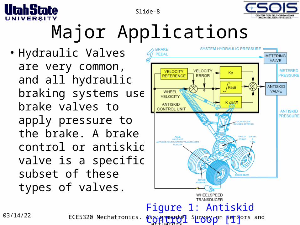
Major Applications• Hydraulic Valves are
very common, and all hydraulic braking systems use brake valves to apply pressure to the brake. A brake control or antiskid valve is a specific subset of these types of valves.
04/18/23 ECE5320 Mechatronics. Assignment#1 Survey on sensors and actuators
Slide-8
Figure 1: Antiskid Control Loop [1]
04/18/23 ECE5320 Mechatronics. Assignment#1 Survey on sensors and actuators
Slide-9
Major Applications • The brake control or antiskid valve is usually in addition
to the typical hydraulic valve that applies pressure to the brakes, although they can be combined. Its usual purpose is not to apply pressure to the brake, but rather to release pressure according to a controller that is determining over-braking conditions (e.g. skidding).
• Some systems combine the braking valve and the antiskid valve into a single valve, and so its purpose is to apply brake pressure according to a combination of pilot input and a brake controller.
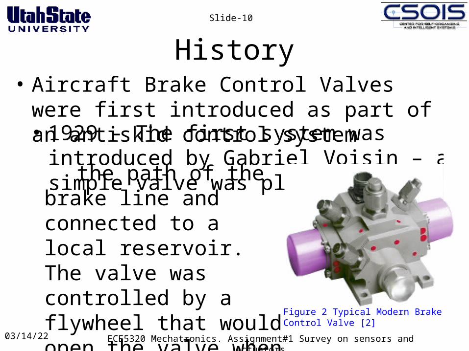
History• Aircraft Brake Control Valves were first
introduced as part of an antiskid control system
04/18/23 ECE5320 Mechatronics. Assignment#1 Survey on sensors and actuators
Slide-10
• 1929 - The first system was introduced by Gabriel Voisin – a simple valve was placed in
the path of the brake line and connected to a local reservoir. The valve was controlled by a flywheel that would open the valve when it spun faster than a drum connected to the wheel
Figure 2 Typical Modern Brake Control Valve [2]
History• 1946 – Hydro-aire Hytrol System implemented
on the B-47. Utilized a simple solenoid based valve that would either be completely closed and apply all pressure commanded by the brake master cylinder or completely release (to system pressure) all pressure going to the brake
• 1960’s – Hydro-aire Mark II System available – utilized a servo-based valve that could modulate the amount of brake pressure that would be applied to the brake
04/18/23 ECE5320 Mechatronics. Assignment#1 Survey on sensors and actuators
Slide-11
Basic Operating Principle• There are 2 broad application types of Brake
Control Valves– Antiskid Control Valve (Release Commanded Valve)– Brake By Wire Valve (Application Commanded
Valve)
• These application types are most commonly implemented as: electro-hydraulic pressure valves
04/18/23 ECE5320 Mechatronics. Assignment#1 Survey on sensors and actuators
Slide-12
Basic Operating Principle• These types of valves typically include the
following characteristic:– Two Hydraulic Stages
• The first stage is a small amount of fluid slightly separated from the body and it acts to adjust the pressure according to the movement of the lever inside which is activated by the attached electric servo
• The second stage is the primary body of the valve where the real pressure fluid fluctuations are occurring. It responds to the changes in pressure balance of the first stage to react similarly. This is similar to a cascaded controller system, where the first stage is the controller and the second stage is the plant modified by a gain
04/18/23 ECE5320 Mechatronics. Assignment#1 Survey on sensors and actuators
Slide-13
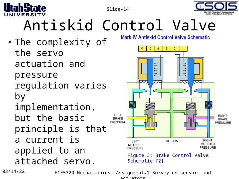
Antiskid Control Valve• The complexity of
the servo actuation and pressure regulation varies by implementation, but the basic principle is that a current is applied to an attached servo.
04/18/23 ECE5320 Mechatronics. Assignment#1 Survey on sensors and actuators
Slide-14
Figure 3: Brake Control Valve Schematic [2]
Antiskid Control Valve• Varying current levels through the solenoid will
apply various amounts of force to an internal poppet that will move between return and metered pressure, thus modulating the amount of pressure being sent to the brake.
• The key aspect to this valve is that the valve functions as a simple bypass when the servo is not activated, so it can only affect the pressure that is being applied, it cannot add pressure to the system.
04/18/23 ECE5320 Mechatronics. Assignment#1 Survey on sensors and actuators
Slide-15
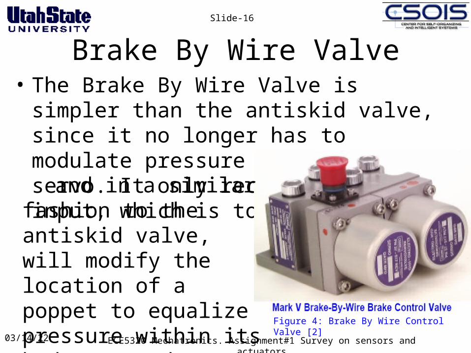
Brake By Wire Valve• The Brake By Wire Valve is simpler than the
antiskid valve, since it no longer has to modulate pressure through a servo. It only receives one input, which is to a servo,
04/18/23 ECE5320 Mechatronics. Assignment#1 Survey on sensors and actuators
Slide-16
Figure 4: Brake By Wire Control Valve [2]
and in a similar fashion to the antiskid valve, will modify the location of a poppet to equalize pressure within its body to send system pressure to the brake.
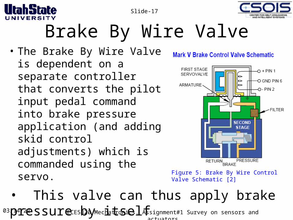
Brake By Wire Valve• The Brake By Wire Valve
is dependent on a separate controller that converts the pilot input pedal command into brake pressure application (and adding skid control adjustments) which is commanded using the servo.
04/18/23 ECE5320 Mechatronics. Assignment#1 Survey on sensors and actuators
Slide-17
Figure 5: Brake By Wire Control Valve Schematic [2]
• This valve can thus apply brake pressure by itself
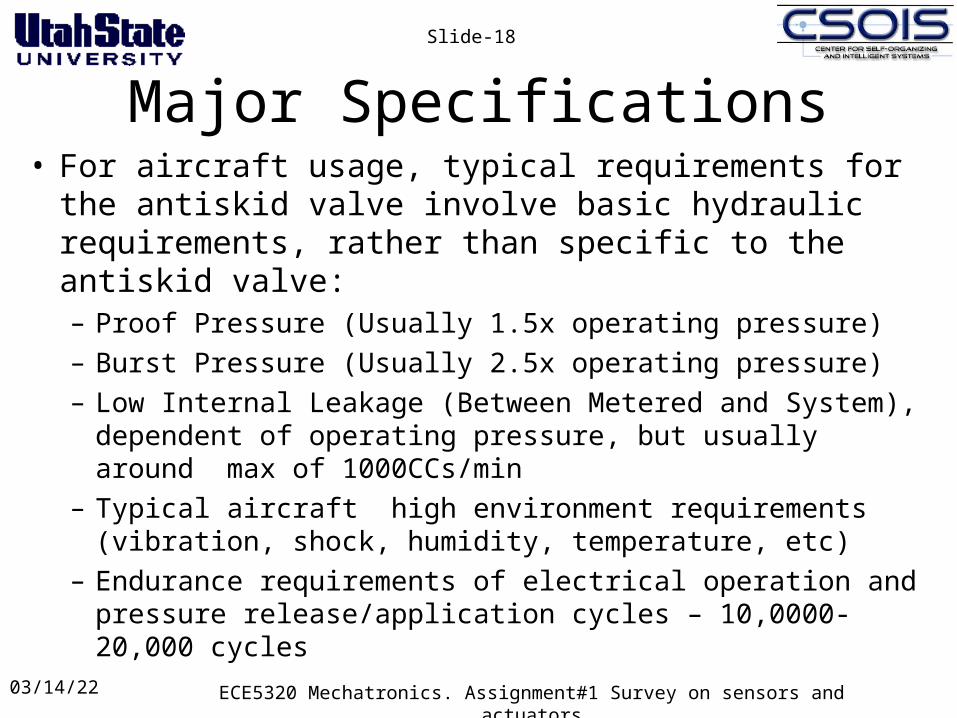
Major Specifications• For aircraft usage, typical requirements for the antiskid
valve involve basic hydraulic requirements, rather than specific to the antiskid valve:– Proof Pressure (Usually 1.5x operating pressure)
– Burst Pressure (Usually 2.5x operating pressure)
– Low Internal Leakage (Between Metered and System), dependent of operating pressure, but usually around max of 1000CCs/min
– Typical aircraft high environment requirements (vibration, shock, humidity, temperature, etc)
– Endurance requirements of electrical operation and pressure release/application cycles – 10,0000-20,000 cycles
04/18/23 ECE5320 Mechatronics. Assignment#1 Survey on sensors and actuators
Slide-18
Limitations• The use of Hydraulic Actuators are limited by the
predominantly non-linear nature of hydraulic fluid and pressure responses
• Aspects of the system are difficult to measure or to estimate during operation:– Viscosity, Temperature, oil bulk modulus
• Despite typically offering fast responses due to low inertia of the valve, there are always issues with delays due to connecting lines
04/18/23 ECE5320 Mechatronics. Assignment#1 Survey on sensors and actuators
Slide-19
Benefits• Hydraulic power/actuators offer:
– High power to weight ratio – Reliable, self-lubricating operation
• The Antiskid valve fits simply within typical hydraulic braking systems
• Long history of hydraulic systems usage – even though not well model-able, has established usage history. Modeling is worked around using Hardware in the Loop for the hydraulic systems
04/18/23 ECE5320 Mechatronics. Assignment#1 Survey on sensors and actuators
Slide-20
Future Work• Electric braking system actuators are starting to emerge
in the marketplace, such as are set for the upcoming Boeing 787 (which will have electric brakes)
• More work needs to be done on this systems regarding reliability, design capability, modeling, efficiency and cost
• It is also not well understood how much benefit will be gained by converting all these systems to electrical at this time. As has been borne out with other mechanical systems, they are piecewise converted to electrical, as design tools, software methods and other control aspects are worked out and made efficient, cheap and reliable.
04/18/23 ECE5320 Mechatronics. Assignment#1 Survey on sensors and actuators
Slide-21