Embed Size (px)
Citation preview
AIRCRAFT ACCIDENT REPORT 3/2009
Air Accidents Investigation Branch
Department for Transport
Report on the serious incident toBoeing 737-3Q8, registration G-THOF
on approach to Runway 26Bournemouth Airport, Hampshire
on 23 September 2007
This investigation was carried out in accordance withThe Civil Aviation (Investigation of Air Accidents and Incidents) Regulations 1996
The sole objective of the investigation of an accident or incident under these Regulations shall be the prevention of accidents and incidents. It shall not be the purpose of such an
investigation to apportion blame or liablility.
ii
© Crown Copyright 2009
Printed in the United Kingdom for the Air Accidents Investigation Branch
Published with the permission of the Department for Transport (Air Accidents Investigation Branch).
This report contains facts which have been determined up to the time of publication. This information is published to inform the aviation industry and the public of the general circumstances of accidents and serious incidents.
Extracts may be published without specific permission providing that the source is duly acknowledged.
Published 21 May 2009
iii
RECENT FORMAL AIRCRAFT ACCIDENT AND INCIDENT REPORTSISSUED BY THE AIR ACCIDENTS INVESTIGATION BRANCH
THE FOLLOWING REPORTS ARE AVAILABLE ON THE INTERNET AThttp://www.aaib.gov.uk
1/2008 Bombardier CL600-2B16 Challenger 604, VP-BJM January 2008 8 nm west of Midhurst VOR, West Sussex on 11 November 2005.
2/2008 Airbus A319-131, G-EUOB January 2008 during the climb after departure from London Heathrow Airport on 22 October 2005. 3/2008 British Aerospace Jetstream 3202, G-BUVC February 2008 at Wick Aerodrome, Caithness, Scotland on 3 October 2006.
4/2008 Airbus A320-214, G-BXKD February 2008 at Runway 09, Bristol Airport on 15 November 2006.
5/2008 Boeing 737-300, OO-TND April 2008 at Nottingham East Midlands Airport on 15 June 2006.
6/2008 Hawker Siddeley HS 748 Series 2A, G-BVOV August 2008 at Guernsey Airport, Channel Islands on 8 March 2006.
7/2008 Aerospatiale SA365N, G-BLUN October 2008 near the North Morecambe gas platform, Morecambe Bay on 27 December 2006.
1/2009 Boeing 737-81Q, G-XLAC January 2009 Avions de Transport Regional ATR-72-202, G-BWDA, and Embraer EMB-145EU, G-EMBO at Runway 27, Bristol International Airport on 29 December 2006 and 3 January 2007.
2/2009 Boeing 777-222, N786UA April 2009 at London Heathrow Airport on 26 February 2007.
iv
Department for TransportAir Accidents Investigation BranchFarnborough HouseBerkshire Copse RoadAldershotHampshire GU11 2HH
April 2009
The Right Honourable Geoff HoonSecretary of State for Transport
Dear Secretary of State
I have the honour to submit the report by Mr K Conradi, an Inspector of Air Accidents, on the circumstances of the incident to Boeing 737-3Q8, registration G-THOF, on approach to Runway 26, Bournemouth Airport, Hampshire on 23 September 2007.
Yours sincerely
David KingChief Inspector of Air Accidents
v
Contents
Synopsis ............................................................................................................................ 1
1 Factual Information .............................................................................................. 3
1.1 History of the flight ........................................................................................ 3
1.2 Injuries to persons .......................................................................................... 6
1.3 Damage to aircraft .......................................................................................... 7
1.4 Other damage ................................................................................................. 7
1.5 Personnel information .................................................................................... 7
1.5.1 Commander ...................................................................................... 71.5.2 First Officer ...................................................................................... 7
1.6 Aircraft information ....................................................................................... 81.6.1 Leading Particulars .......................................................................... 81.6.2 Autothrottle system .......................................................................... 81.6.3 Autothrottle disengagement ........................................................... 101.6.4 Built-in Test Equipment (BITE) fault history ................................ 111.6.5 Aircraft fault history ...................................................................... 11
1.7 Meteorological information ......................................................................... 111.7.1 Forecast .......................................................................................... 111.7.2 Meteorological information received en route. .............................. 11
1.8 Aids to navigation ........................................................................................ 12
1.9 Communications .......................................................................................... 12
1.10 Aerodrome information ................................................................................ 12
1.11 Flight Recorders ........................................................................................... 131.11.1 FDR/CVR ...................................................................................... 131.11.2 Radar Recording ............................................................................ 13
1.12 Wreckage and impact information ............................................................... 13
1.13 Medical and pathological ............................................................................. 13
1.14 Fire ............................................................................................................... 13
1.15 Survival aspects............................................................................................ 13
1.16 Tests and research ........................................................................................ 151.16.1 General ........................................................................................... 151.16.2 Autothrottle system testing ............................................................ 15
vi
1.16.3 Autothrottle computer testing ........................................................ 151.16.4 Autothrottle operation statistics ..................................................... 161.16.5 Aircraft manufacturer’s QAR performance analysis ..................... 17
1.17 Organisational and management information .............................................. 181.17.1 ASR processing .............................................................................. 181.17.2 The Mandatory Occurrence Reporting Scheme ............................. 201.17.3 MOR scheme CAP 382 - items to be reported............................... 20
1.18 Additional information ................................................................................. 211.18.1 Similar events ................................................................................ 211.18.2 EASA CS-25 certification requirements ........................................ 211.18.3 UK CAA Paper 2004/10 Flight Crew Reliance on Automation .... 231.18.4 Flight crew training and manuals ................................................. 23
1.18.4.1 Operations Manual Part B ......................................... 231.18.4.2 The operator’s Quick Reference Handbook (QRH) procedure for approach to stall recovery. .................... 241.18.4.3 The operator’s QRH procedure for upset recovery ..... 241.18.4.4 Flight Crew Training Manual ...................................... 251.18.4.5 ‘Airplane’ upset recovery training aid ........................ 26
1.18.5 Pitch power couple ......................................................................... 27
2 Analysis ................................................................................................................. 29
2.1 Introduction .................................................................................................. 292.1.1 Autothrottle disengagement ........................................................... 292.1.2 Disengagement alerting requirements ........................................... 30
2.2 Crew reactions .............................................................................................. 31
2.3 Aircraft pitch excursion ............................................................................... 32
2.4 ASR ............................................................................................................. 35
2.5 The MOR Scheme ........................................................................................ 37
3 Conclusions .......................................................................................................... 39
3.1 Findings ........................................................................................................ 39
3.2 Causal factors ............................................................................................... 41
3.3 Contributory factors ..................................................................................... 41
4 Safety Recommendations .................................................................................... 42

vii
Appendices
Appendix A Fault History
Appendix B Operator Procedures
Appendix C Extracts from: Manufacturer’s Upset Recovery Training Aid
viii
GLOSSARY OF ABBREVIATIONS USED IN THIS REPORT
AAIB Aircraft Accidents Investigation Branchaal above airfield levelAFCS Automatic Flight Control SystemsAMM Aircraft Maintenance ManualASR Air Safety ReportATC Air Traffic Control ATE Automatic Test EquipmentATIS Automatic Terminal Information SystemATP Automatic Test ProcedureBITE Built-In Test EquipmentCAA Civil Aviation AuthorityCAS Calibrated Air SpeedCS Certification StandardsCVR Cockpit Voice RecorderCWS Control Wheel Steer°M,T magnetic, trueDME Distance Measuring EquipmentEASA European Aviation Safety AgencyEICAS Engine Indication and Crew Alerting SystemFAA Federal Aviation Regualtion (USA)FCTM Flight Crew Training ManualFDM Flight Data MonitoringFDR Flight Data RecorderFFS Full Flight SimulatorFMC Flight Management ComputerF/O First OfficerFORCE Flight Operations Research Centre of Excellence
ft feethrs hours (clock time as in 12:00 hrs)ILS Instrument Landing SystemIMC Instrument Meteorological ConditionsJAA Joint Aviation Authorieskt knot(s)m metresmb millibar(s)MCP Mode Control PanelMHz MegahertzMOR Mandatory Occurrence ReportN1 engine fan or LP compressor speednm nautical mile(s)NPA Notice of Proposed AmendmentOFDM Operational Flight Date MonitoringPF Pilot FlyingPM Pilot MonitoringPNF Pilot Not FlyingQAR Quick Access RecorderQNH pressure setting to indicate elevation above mean sea levelQRH Quick Reference HandbookTAF Terminal Aerodrome ForecastTOGA Takeoff or Go-aroundTRTO Type Rating Training OrganisationUTC Co-ordinated Universal Time (GMT)VREF Reference airspeed (approach)
1
Air Accidents Investigation Branch
Aircraft Accident Report No: 3/2009 (EW/C2007/09/12)
Registered Owner and Operator Thomsonfly Ltd
Aircraft Type Boeing 737-3Q8
Nationality British
Registration G-THOF
Place of Incident On approach to Runway 26 at Bournemouth Airport, Hampshire
Date and Time 23 September 2007 at 2250 hrs (All times in this report are UTC)
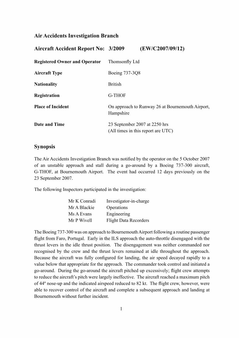
Synopsis
The Air Accidents Investigation Branch was notified by the operator on the 5 October 2007 of an unstable approach and stall during a go-around by a Boeing 737-300 aircraft, G-THOF, at Bournemouth Airport. The event had occurred 12 days previously on the 23 September 2007.
The following Inspectors participated in the investigation:
Mr K Conradi Investigator-in-chargeMr A Blackie OperationsMs A Evans EngineeringMr P Wivell Flight Data Recorders
The Boeing 737-300 was on approach to Bournemouth Airport following a routine passenger flight from Faro, Portugal. Early in the ILS approach the auto-throttle disengaged with the thrust levers in the idle thrust position. The disengagement was neither commanded nor recognised by the crew and the thrust levers remained at idle throughout the approach. Because the aircraft was fully configured for landing, the air speed decayed rapidly to a value below that appropriate for the approach. The commander took control and initiated a go-around. During the go-around the aircraft pitched up excessively; flight crew attempts to reduce the aircraft’s pitch were largely ineffective. The aircraft reached a maximum pitch of 44º nose-up and the indicated airspeed reduced to 82 kt. The flight crew, however, were able to recover control of the aircraft and complete a subsequent approach and landing at Bournemouth without further incident.
2
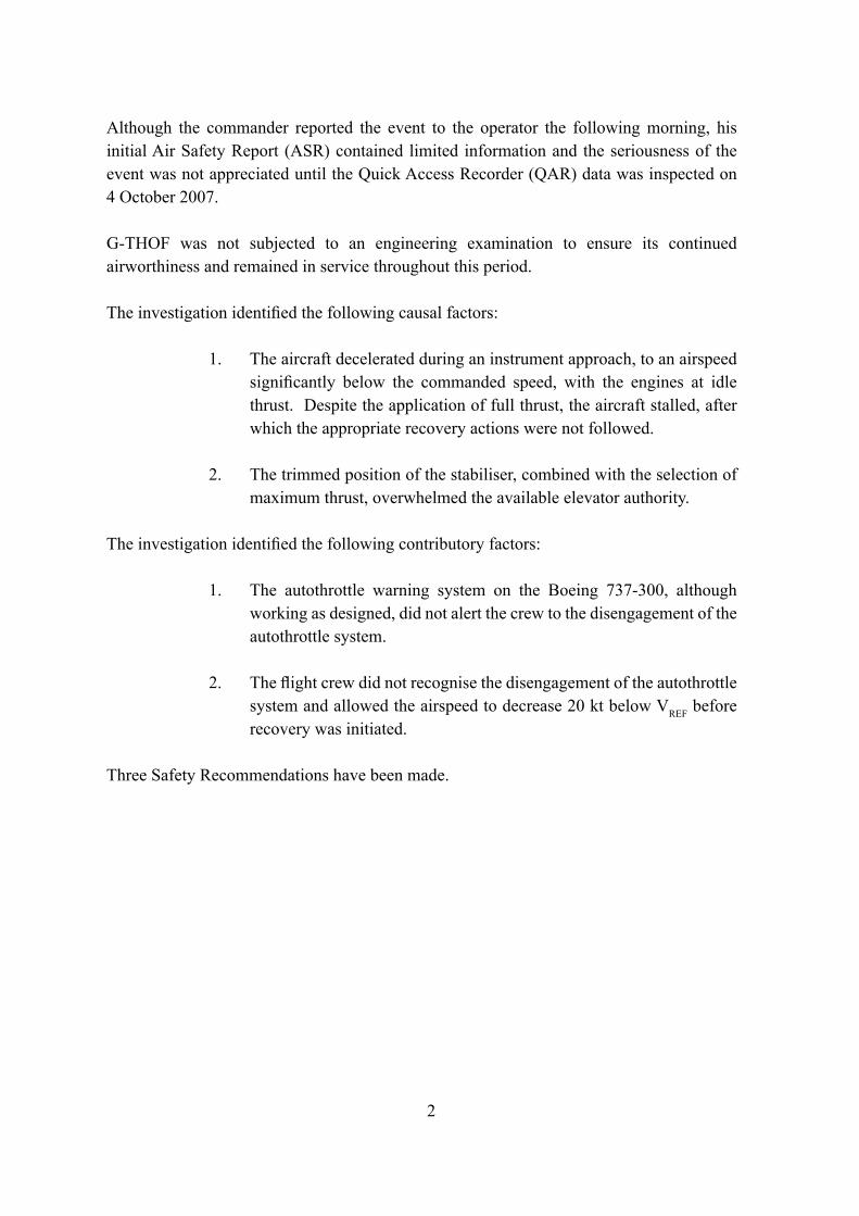
Although the commander reported the event to the operator the following morning, his initial Air Safety Report (ASR) contained limited information and the seriousness of the event was not appreciated until the Quick Access Recorder (QAR) data was inspected on 4 October 2007.
G-THOF was not subjected to an engineering examination to ensure its continued airworthiness and remained in service throughout this period.
The investigation identified the following causal factors:
1. The aircraft decelerated during an instrument approach, to an airspeed significantly below the commanded speed, with the engines at idle thrust. Despite the application of full thrust, the aircraft stalled, after which the appropriate recovery actions were not followed.
2. The trimmed position of the stabiliser, combined with the selection of maximum thrust, overwhelmed the available elevator authority.
The investigation identified the following contributory factors:
1. The autothrottle warning system on the Boeing 737-300, although working as designed, did not alert the crew to the disengagement of the autothrottle system.
2. The flight crew did not recognise the disengagement of the autothrottle system and allowed the airspeed to decrease 20 kt below VREF before recovery was initiated.
Three Safety Recommendations have been made.
3
1 Factual Information
1.1 Historyoftheflight
This section is based on information gathered during crew interviews and data retrieved from the QAR. The Cockpit Voice Recorder (CVR) and Flight Data Recorder (FDR) recordings had been overwritten and therefore the incident flight information was unavailable.
G-THOF was planned to operate from Faro in Portugal to Bournemouth, Hampshire on a scheduled night passenger flight with the First Officer (F/O) as pilot flying (PF). Before departing Faro the crew discussed the weather at Bournemouth, uplifted additional fuel to permit two approaches and decided on a full flap (flap 40) landing. As part of the pre-flight actions the PF programmed the Flight Management Computer (FMC) for a final approach commencing at 10 nm. During the cruise the PF briefed the approach and reiterated his intention to use flap 40 for the landing. Both pilots confirmed the flap 40 reference speed (VREF 40) of 129 kt and the intended final approach speed of 135 kt (VREF 40 +6). The flight was routine until the approach at Bournemouth.
There was no other traffic in the area so the crew were cleared to self-position for the ILS approach to Runway 26. At 2245 hrs the aircraft was 11 nm from Bournemouth, level at 2500 ft, with a Calibrated Air Speed (CAS) of 180 kt and flap 5 set. The autothrottle was engaged in speed mode1, with N1
2 averaging approximately 60%. Autopilot B was engaged in CMD mode with VOR-LOC and Altitude Hold modes engaged.
The aircraft was level at 2,500 ft for 90 seconds and at seven nm DME the autopilot captured the glideslope. The PF asked for the landing gear to be lowered, flap 15 to be selected and the landing check list. The commander carried out the actions although neither pilot could recall who had moved the speedbrake handle, which was placed at 12º, slightly beyond the armed setting of 9º. The PF then selected a lower speed on the mode control panel (MCP) and, as expected, the autothrottle retarded the thrust levers to idle to reduce to this speed.
The aircraft started to descend on the glideslope, and about 20 seconds later, with the thrust levers still at idle the autothrottle disconnect warning
1 Speed mode will attempt to fly the airspeed selected by the flightcrew on the mode control panel.2 N1 is the rotational speed of the first stage of the engine compressor. Expressed in a percentage it is used as a guide
to the amount of power the engine is producing.
4
was triggered and the autothrottle disengaged.3 This disengagement was not recognised by the flight crew and no manual disconnect was recorded4; the thrust levers remained at idle throughout the remainder of the approach.
The autopilot remained engaged and continued to track both the localiser and the glideslope. The aircraft’s speed decayed at about one knot per second, in line with the PF’s expectations for the approach. As the speed decreased below 150 kt, flap 25 was selected. The autopilot tracked the glideslope accurately, gradually increasing the pitch of the aircraft to minimise glideslope deviation and adjusting the stabiliser angle to keep the aircraft in trim. Temporary reductions in pitch were evident during flap position transitions.
The PF increased the illumination of his maplight to check the placard speed for the selection of flap 40, turned his light back to its previous level and called for flap 40. The commander moved the flap lever and the PF then selected 135 kt on the MCP. The commander observed the flaps move to the flap 40 position and then completed the landing checklist by calling “FLAPS”. The PF checked the flap gauge showed 40 and responded “FLAP 40 GREEN LIGHT5”. Recorded data shows the flaps had reached the flap 40 position when the airspeed was 130 kt (Final Approach Speed -5 kt) and the aircraft was slowing at approximately 1.5 kt per second. The commander stowed the checklist on top of the instrument panel and when he looked down he saw an IAS of 125 kt. He called “SPEED”, the PF made a small forward movement with the thrust levers and the commander called “I HAVE CONTROL”. The commander moved the thrust levers fully forward and called “GO-AROUND FLAP 15 CHECK
THRUST”.
Recorded data shows that, at a CAS of 110 kt and an altitude of 1,540 ft, the autothrottle manual disconnect was pressed and the thrust levers moved forward slightly. Within 1.5 seconds the stick-shaker (stall warning) activated and in the following two seconds the thrust levers were advanced to the full forward position. The autopilot mode changed from localiser and glideslope to Control Wheel Steer (CWS) pitch and CWS roll6. The aircraft pitch attitude which had been steadily increasing under the influence of pitch trim, reached 12º nose-up. The automatic pitch trim stopped at 4.9º (7.9 units) of stabiliser trim.
The commander moved the control column forward to counteract the expected
3 The methods of recording these events are different and it is plausible that they occurred in the reverse order. 4 Manual disconnect of the autothrottle is sampled eight times a second.5 Referring to the leading edge lift devices.6 With CWS mode engaged the autopilot manoeuvres the aircraft in response to manually applied pressure on either
pilot’s control column.
5
pitch-up moment from the increased thrust, which arrested the increase and reduced the pitch to 5º nose-up. The stick-shaker operation stopped and the minimum airspeed was 101 kt. A small, apparently unintended application of right aileron induced a right roll.
Four seconds after the thrust levers reached the fully forward position, with airspeed increasing and N1 on both engines increasing through 81%, the TOGA mode became active. The autopilot disengaged, the pitch attitude started to increase again and the stick-shaker reactivated. A corrective roll input was made to bring the aircraft wings level, and although the control column was positioned fully forward the nose-up pitch increased to 22º.
The airspeed increased to 118 kt CAS. The pitch attitude appeared to stabilise at 22º nose-up and the angle of attack started to decrease. Both engines were producing 96-98% N1, which was in excess of the rated go-around thrust of 94%. The first officer selected the flaps to 15 and looked at the N1 reading which he recalls as being 95%. The stick-shaker ceased but, as the flaps retracted past the flap 25 position, the nose of the aircraft began to pitch up at an increasing rate and a small continuous left rudder input started a left roll. As the flaps reached flap 15 the pitch angle was increasing through 27º and left roll was increasing through 7º. The stick-shaker reactivated, full nose-down elevator was still being applied and the airspeed began to decay. The first office called “HIGH PITCH” and the commander responded “I HAVE
FULL FORWARD STICK”.
The F/O, although he was now the Pilot Monitoring (PM)7, also held full forward stick; both pilots reported that they had no pitch control authority. The airspeed had decreased rapidly but neither pilot was fully aware of exactly what the airspeed was.
As aircraft pitch increased above 36º nose-up, the TOGA mode disengaged, the left roll increased beyond 13º and the CAS decreased below 107 kt. A small sharp right rudder input recovered the roll from a maximum of 22º left wing down to wings level as the aircraft stalled with a peak pitch of 44º nose-up. With no change in elevator position the pitch rate reversed from positive to negative, although angle of attack continued to increase as the aircraft started to descend. Despite reducing pitch, the airspeed continued to decrease for a further five seconds to a minimum recorded CAS of 82 kt when the pitch was 33º nose-up.
7 This role was previously known as Pilot Not Flying (PNF). PM is now common as it more accurately describes the role.
6
The pitch angle reduced to 20º over 10 seconds, airspeed began to rise rapidly and five seconds after the minimum recorded speed, the thrust was reduced to 86%. The pitch-down rate increased with the pitch reducing a further 15º in two seconds.
The aircraft then stabilised in a 5º nose-up attitude, the speed increased and the commander regained control of the aircraft. The TOGA mode was re-engaged as the CAS reached 147 kt.
The commander initially levelled the aircraft at 3,000 ft before climbing to 4,000 ft and self positioning for a second approach. While downwind the F/O told the commander that “THE AUTOTHROTTLE DID NOT CAPTURE IT”. The commander remained PF throughout the second approach which was conducted with the autopilot and the autothrottle engaged. Both auto systems performed normally throughout the second approach. The autopilot and autothrottle were manually disengaged at 1,200 ft and 800 ft respectively and the aircraft landed at 2301 hrs.
After the engines were shut down on stand, the commander spoke with the operator’s base engineer. He told the engineer that, although he thought that the aircraft was serviceable, there had been an incident and the company would want the flight data. No defects were entered in the technical log. The engineer assured the captain that the Operational Flight Data Monitoring (OFDM) information was sent from the aircraft by an automatic mobile telephone based datalink. The commander and F/O discussed the incident before going off duty.
The next morning the commander returned to the airfield and telephoned the operator’s safety department to advise them of the incident. He completed an operator Air Safety Report (ASR) using the company’s internet based system. This ASR was not reported to the Civil Aviation Authority until 4 October 2007.
1.2 Injuries to persons
Injuries Crew Passengers OthersFatal 0 0 0Serious 0 0 0None 5 132 0
7
1.3 Damage to aircraft
None.
1.4 Other damage
None.
1.5 Personnel information
1.5.1 Commander
Male, Age 56 yearsLicence: Airline Transport Pilot’s LicenceLPC/OPC renewed: 12 May 2007Line check renewed: 28 July 2007Medical certificate: JAA Class 1 issued 20 March 2007Flying experience: Total 11,280 hours (of which 420 were on type) Last 90 days 190 hours Last 28 days 75 hours Last 24 hours 5 hoursPrevious rest period: 15 hours 45 mins
The commander had previously spent approximately 17 years on the operator’s Boeing 757/767 fleet as a first officer and had completed a combined type conversion and command upgrade course in 2006.
1.5.2 First Officer
Male, Age 30 yearsLicence: Commercial Pilot’s LicenceLPC/OPC renewed: 12 June 2007Line check renewed: 19 April 2007Medical certificate: JAA Class 1 Issued 6 August 2007Flying experience: Total 3,170 hours (of which 845 were on type) Last 90 days 170 hours Last 28 days 58 hours Last 24 hours 0 hoursPrevious rest period: 36 hours
The first officer had previously flown DHC Dash 8-300 aircraft for a different company before joining the operator and converting to the Boeing 737 in 2006.
8
The crew, who were both based at Bournemouth, commented that flap 40 landings were not normally conducted by Bournemouth based crews as only one of their normal destinations required it’s use for performance reasons. Neither pilot reported any medical or fatigue issues which they considered could have affected their performance.
1.6 Aircraft information
1.6.1 Leading Particulars
Registration G-THOFType Boeing 737-3Q8Serial No 26314Year of Manufacture 1995Airframe life at time of incident 37,061 hours on 23/9/07Engines 2 x CFM56-3C1 (22,000lbs thrust each)Serial Numbers L/H 858302 R/H 858245Hours/Cycles L/H 32,621 hrs/18,465 cycles R/H 34,842 horus/19,667 cycles (at 16/10/07)
The aircraft held a current EASA Standard Certificate of Airworthiness, valid until 27 March 2008
The last maintenance carried out was a 1A check on 20 September 2007.
There were no relevant deferred defects or technical log entries.
The aircraft weight and balance was within the prescribed limits.
The autothrottle computer (Boeing Part No 10-62017-30, Manufacturer’s P/N 735SUE10-12, S/N 5593) had been fitted to G-THOF on 24 February 2002. It was removed following another autothrottle disengagement on 22 October 2007 described in paragraph 1.18.1 of this report (see page 21).
1.6.2 Autothrottle system
The autothrottle system automatically positions the thrust levers to maintain a computed engine thrust level and forms part of the Automatic Flight Control Systems (AFCS). It comprises a digital autothrottle computer, two autothrottle servo mechanisms, two thrust lever synchros and various pilot
9
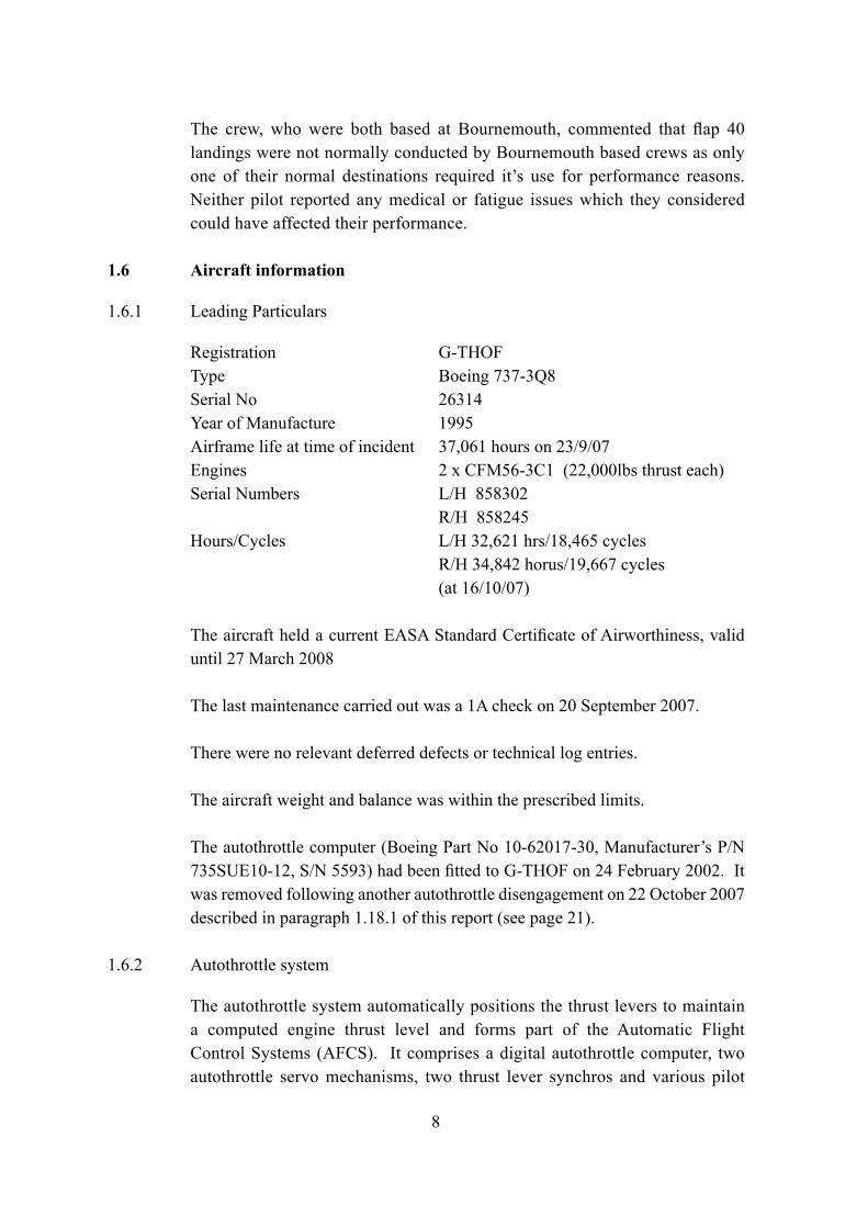
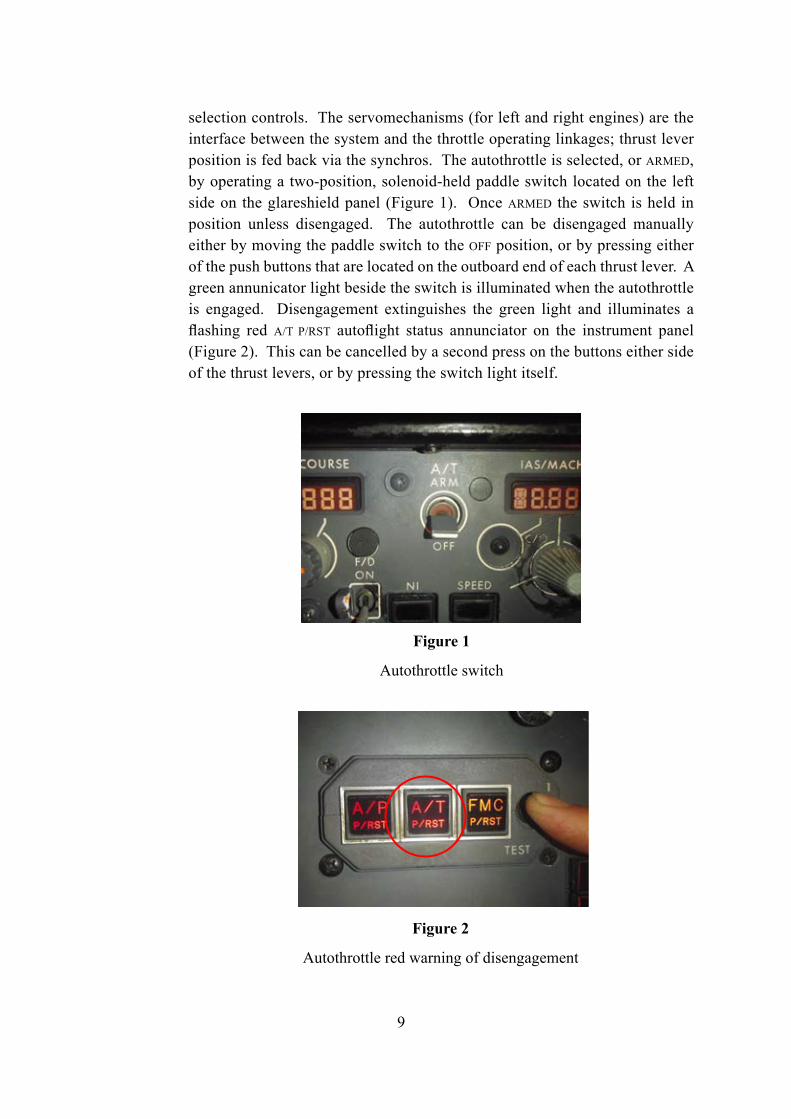
selection controls. The servomechanisms (for left and right engines) are the interface between the system and the throttle operating linkages; thrust lever position is fed back via the synchros. The autothrottle is selected, or ARMED, by operating a two-position, solenoid-held paddle switch located on the left side on the glareshield panel (Figure 1). Once ARMED the switch is held in position unless disengaged. The autothrottle can be disengaged manually either by moving the paddle switch to the OFF position, or by pressing either of the push buttons that are located on the outboard end of each thrust lever. A green annunicator light beside the switch is illuminated when the autothrottle is engaged. Disengagement extinguishes the green light and illuminates a flashing red A/T P/RST autoflight status annunciator on the instrument panel (Figure 2). This can be cancelled by a second press on the buttons either side of the thrust levers, or by pressing the switch light itself.
Figure 1
Autothrottle switch
Figure 2
Autothrottle red warning of disengagement
10
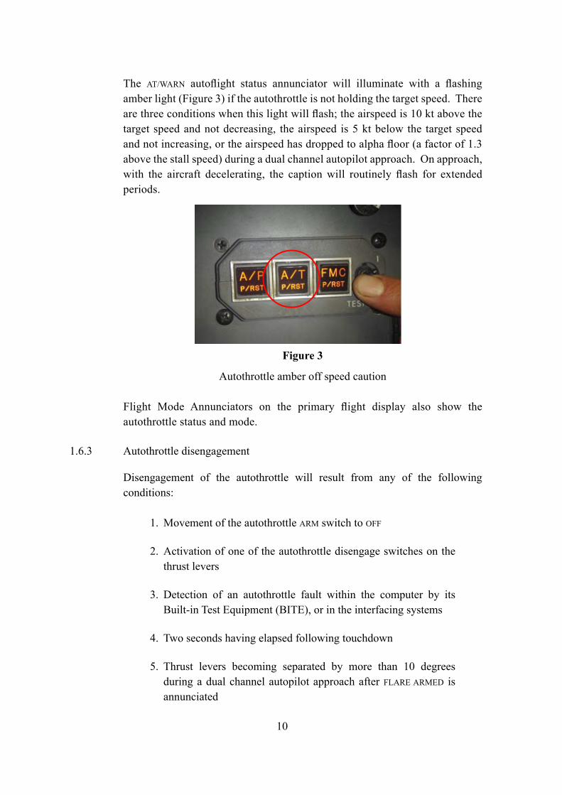
The AT/WARN autoflight status annunciator will illuminate with a flashing amber light (Figure 3) if the autothrottle is not holding the target speed. There are three conditions when this light will flash; the airspeed is 10 kt above the target speed and not decreasing, the airspeed is 5 kt below the target speed and not increasing, or the airspeed has dropped to alpha floor (a factor of 1.3 above the stall speed) during a dual channel autopilot approach. On approach, with the aircraft decelerating, the caption will routinely flash for extended periods.
Figure 3
Autothrottle amber off speed caution
Flight Mode Annunciators on the primary flight display also show the autothrottle status and mode.
1.6.3 Autothrottle disengagement
Disengagement of the autothrottle will result from any of the following conditions:
1. Movement of the autothrottle ARM switch to OFF
2. Activation of one of the autothrottle disengage switches on the thrust levers
3. Detection of an autothrottle fault within the computer by its Built-in Test Equipment (BITE), or in the interfacing systems
4. Two seconds having elapsed following touchdown
5. Thrust levers becoming separated by more than 10 degrees during a dual channel autopilot approach after FLARE ARMED is annunciated
11
6. Autopilot roll control requiring significant spoiler deployment and thrust levers becoming separated, when flaps are less than 15º8 and the autothrottle is not in take-off or go-around mode
Autothrottle disengagement results in the ARM switch releasing to OFF and the red autothrottle disengage lights flashing unless it has disengaged automatically after touchdown when the lights will not illuminate.
Manual positioning of the thrust levers does not normally cause autothrottle disengagement.
1.6.4 Built-in Test Equipment (BITE) fault history
The autothrottle computer contains a BITE program to monitor its function and non-volatile memory to store fault information for the last 10 flights. Due to the delay in notification of the incident the aircraft had completed more than 10 flights and therefore the fault history information from the incident had been overwritten.
1.6.5 Aircraft fault history
A recent fault history for the aircraft is included in Appendix A.
1.7 Meteorological information
1.7.1 Forecast
As part of the flight brief the crew received forecast weather for Bournemouth before departure from Faro.
The weather provided was the 1807 hrs TAF valid between 1900 hrs and 0100 hrs. It forecast a surface wind of 200°/14 kt, 6,000 m visibility with cloud broken at 800 ft. Temporary between 1900 hrs and 0100 hrs the visibility was expected to reduce to 2,000 m in light rain and mist with cloud broken at 300 ft and a 40% probability that temporarily, between 1900 hrs and 0100 hrs the surface wind would be 200°/15 kt gusting to 25 kt.
1.7.2 Meteorological information received en route.
The last weather report recorded by the crew as they approached Bournemouth was ATIS ‘H’ recorded at 2220 hrs. It reported Runway 26 in use with wind
8 This is monitored at the flap and not at the cockpit control. Therefore it is possible for the mode to be active with the flap lever in the Flap 15 position if the flaps have not reached 15° deployment.
12
220°/14 kt, 4,000 m visibility in light rain, cloud overcast at 400 ft, temperature and dewpoint plus 17ºC. The QNH was 1011 mb. The weather at the time of the incident was the same.
Throughout the incident the aircraft was operating in Instrument Meteorological Conditions (IMC) at night.
1.8 Aids to navigation
At the time of the incident the aircraft was established on the ILS to Runway 26 at Bournemouth Airport.
Runway 26 was equipped with a category one ILS DME transmitting on a frequency of 110.5 Mhz with an approach gradient of 3º. The ILS was orientated on the runway track of 258º.
1.9 Communications
Radio communications throughout the approach were routine.
Following the go-around the crew informed ATC that they had conducted a go-around but no mention of the incident was made.
1.10 Aerodrome information
Bournemouth (Hurn) Airport (EGHH) is located on the south coast of England some 3.5 nm NNE of the city of Bournemouth. It has a single runway orientated 26/08 of 2,271 meters length by 46 meters wide. The runway in use at the time of this incident was Runway 26 which was equipped with a CAT 1 ILS with full night lighting including high intensity approach lighting (HIALS) and 3º PAPI. The LDA for Runway 26 was 1,970 m. The standard missed approach for Runway 26 was a climb straight ahead to 4 miles DME then a left turn to return to the BIA locator at 3,000 ft. At the time of the incident a temporary restricted area was in effect over the city of Bournemouth which required a missed approach climb to 4,000 ft to remain clear. The aircraft did not enter this restricted area.

13
1.11 Flight Recorders
1.11.1 FDR/CVR
This incident was reported to the AAIB 12 days after it occurred. This resulted in the loss of Flight Data Recorder (FDR) and Cockpit Voice Recorder (CVR) recordings.
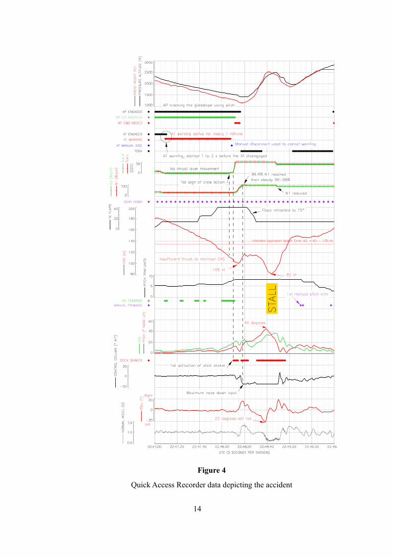
The operator was running an Operational Flight Data Monitoring (OFDM) programme using onboard equipment. This sent a copy of the QAR data to a server at the operator’s headquarters, via a mobile phone service, whenever the aircraft terminated a flight in the UK. This data was made available to the AAIB and extracts are shown in Figure 4.
1.11.2 Radar Recording
Pease Pottage radar recorded the aircraft track, as well as a number of transmitted parameters, at a rate of approximately once every 6 seconds. This information was not as comprehensive as the QAR data so it was used for checking the FDM data only.
Details from the recorded data were used in the construction of Section 1.1, History of the flight (see page 3).
1.12 Wreckage and impact information
Not applicable.
1.13 Medical and pathological
Not applicable.
1.14 Fire
Not applicable.
1.15 Survival aspects
Not applicable.
14
Figure 4
Quick Access Recorder data depicting the accident
15
1.16 Tests and research
1.16.1 General
Both pilots reported that they had not seen the autothrottle disconnect warning. The autothrottle system was functionally tested. The AAIB became aware that there had been a number of other events possibly with similar precursors, ie an autothrottle disconnect followed by a long period of warning without crew recognition. Consequently, the efficacy of the autothrottle warning became of interest to the investigation.
1.16.2 Autothrottle system testing
The autothrottle computer (P/N 735SUE10-12, S/N 5593) from the incident flight was re-fitted to G-THOF and the Aircraft Maintenance Manual (AMM) Task 22-31-00-735-060 autothrottle System Test was carried out on 15 November 2007. The purpose of this test was to confirm the correct functioning of the autothrottle system, including the autothrottle warnings. No faults were found with the system during these tests. The autothrottle computer was subsequently removed for further testing.
1.16.3 Autothrottle computer testing
The autothrottle computer was subjected to a full Automatic Test Procedure (ATP) using the manufacturer’s Automatic Test Equipment (ATE). The computer failed two of these tests which were related to analogue inputs and outputs. These failures appeared to be small tolerance errors that could have been attributable to the ATE, so the computer was then tested on a manual rig where each individual test could be performed and observed. The analogue inputs were checked and the results were within the specification requirements. The analogue outputs were found to be out of tolerance at the extreme negative (-10 Volts) end of the output range (the measured voltages were up to -10.24 Volts). These results indicated that the analogue output on the Output Interface Card was the likely source of the high voltage.
An internal visual inspection of the computer did not show any signs of damage or failure. The Output Interface Card was interchanged with a serviceable card and the analogue outputs were rechecked and were within specification. The original card was returned to the computer but attached to an ‘extender’ card allowing adjustment of the -10 Volt output to within the specified limits. With the adjustment made the computer was then subject to a further ATP which it passed successfully.
16
The Output Interface Card output voltage is used as a reference for the Digital to Analogue Converter circuit, which generates the output signals to the throttle servomechanism amplifiers and the flight director outputs. The same reference signal is used for the autothrottle servo demand signals on both engines. Another analogue output is used by the autothrottle itself as part of the built-in test and if a fault is detected, would record a Digital to Analogue Converter fault code within the fault history.
For this over-voltage to have caused an autothrottle disengagement, the thrust levers would be required to move asymmetrically to generate a ‘throttle split’. This is unlikely as the reference voltage is applied to both engine systems. Any other internal faults which could have caused an autothrottle disengagement are not dependant on the Digital to Analogue Converter reference voltage.
1.16.4 Autothrottle operation statistics
During the investigation, anecdotal information indicated that there may have been problems with the autothrottle alerting system on the Boeing 737 aircraft. The information was not considered to be precise enough alone for conclusions to be drawn. Therefore a more statistically based review of the function of the autothrottle and its warnings was generated.
UK operators of large aircraft are required to run Operational Flight Data Monitoring (OFDM) programmes. These programmes gather data on each flight and analyse it for trends or events that can lead to improved safety strategies. The analysis is largely in the form of setting thresholds of parameter combinations that, if exceeded, highlight the flight for further review. Following an approach from the AAIB a number of operators implemented the following four triggers designed to see how prevalent Boeing 737 autothrottle problems were:
1. An autothrottle warning preceding an autothrottle disconnect
2. An un-commanded autothrottle disconnect
3. An unacknowledged autothrottle disconnect warning
4. An unrecognised and un-commanded autothrottle disconnect
In order to have a high degree of confidence in the data it was decided that these events should be implemented in such a way so as to ensure minimum nuisance triggering, even at the cost of missing some genuine events. The triggered
17
events were broken down by phase of flight and only events associated with the descent, approach and final approach were included in the final results, generating a database of 5,284 sectors.
The algorithm implemented to capture the autothrottle warning preceding an autothrottle disconnect did not capture any other similar events. It is of note that whilst it would have triggered on the incident flight, it would not have triggered on the second occasion when the aircraft autothrottle disconnected itself (see 1.18.1, page 21).
0.4% of sectors flown had an autothrottle disconnect without recording any manual disconnect switch activity. However, the autothrottle can be disconnected using the switch on the mode control panel. This switch is not recorded on the FDR, which makes the action indistinguishable from an uncommanded autothrottle disconnect.
The “unacknowledged autothrottle disconnect warning” algorithm simply highlighted any occasion when the autothrottle warning was active for more than nine seconds. This was taken to be an indication that the warning had not been noticed. It was established that extended warnings occurred on 2.5% of sectors. [Note that this was based on a subset of 2,354 sectors.]
0.3% of sectors had the combination of the autothrottle disconnecting without the use of the manual disconnect switches and the resultant warning lasting for more than 9 seconds.
The study was a ‘first look’ and as such did not yield sufficiently robust results to provide definitive occurrence rates.
1.16.5 Aircraft manufacturer’s QAR performance analysis
The aircraft manufacturer was provided with the recorded data in order to conduct an engineering simulation of the approach and go-around with various configurations and power selections.
The simulation determined that during this event the nose-up pitching moment, generated as the engine thrust increased and by the stabiliser’s trimmed position, overwhelmed the elevator until the recovery after the stall.
The simulation considered the amount of elevator deflection required to trim the aircraft during the go-around manoeuvre. The initial configuration was the baseline recorded data for a point shortly after initiation of the go-around
18
and with engines at 98.4% N1. This showed that the elevator required to trim the aircraft at that stage was near the maximum nose-down deflection available for the 737-300. Therefore there was little or no nose-down pitch capability available.
Other simulations included having the stabiliser set for the intended approach speed or the use of the rated go-around thrust of 94% N1. Both of these configurations allow additional pitch authority (6.1º and 1.7º of elevator deflection respectively).
A kinematic analysis was performed which showed no significant evidence of external influences such as windshear.
The manufacturer was asked to consider the effect of changes in the flap setting. They confirmed that there was a nose-up pitching moment associated with changing the flaps from flap 40 to flap 15. This pitching moment created by the flap change would require approximately 0.1 degrees of stabiliser to maintain a trimmed condition. The trim change due to the flap change was therefore seen to be negligible compared with the trim change due to the thrust increase.
The manufacturer further commented that had the flaps remained at flap 40 and all other parameters remained as they were throughout the event, the aircraft would still have stalled. However it may have taken slightly longer to reach the maximum nose-up pitch.
1.17 Organisational and management information
1.17.1 ASR processing
The commander’s Air Safety Report was received by the operator’s flight safety office the day after the event occurred. All reports received, including this one, were initially assessed for severity by a member of the safety team. Part of this assessment was to decide if a Mandatory Occurrence Report (MOR) was required to be filed with the CAA. To determine if this was required the airline safety office referred to CAP 3829 which has a list of events that require a MOR (see 1.17.3). If additional information was required in order to assist the decision, ASRs were flagged electronically to the OFDM analyst.
This process left the ASR file open on the safety department computer system. The system would then automatically generate an alert if the ASR was going to
9 Civil Aviation Publication 382 – The Mandatory Occurrence Reporting Scheme.
19
breach the company’s internal time limit for closure. At the time of the incident this was set at 30 days.
At the time of the incident the OFDM analyst was located in the same building as the safety department but on a different floor. The OFDM analyst would receive an electronic alert to analyse a specific flight, review the data and respond back to the safety office.
The OFDM analyst was not a pilot and, when an aircrew opinion was required he referred events to one of the company’s pilot representatives (also known as an ‘honest broker’). This system is common UK industry practice.
The pilot representative’s role was to view de-identified flight data safety trends and advise the operator’s safety department. The pilot representatives also liaised with the analyst to follow up ASRs and to place recorded data in context with the ASR for the analyst. In events identified solely from OFDM, they provided the link between the aircrew involved and the management. The pilot representative role was part-time and in addition to his normal flying commitments. At the time of the incident a pilot representative was available in the OFDM office on average once every ten days. A pilot representative was in the OFDM office the day following the incident but due to workload he did not review the data downloaded from the aircraft. The next pilot representative was on duty 11 days after the incident and he reviewed the data and realised the severity of the event. The event was then progressed through the safety system and the AAIB was alerted by the operator. The company OFDM programme followed the guidance of CAP 73910 and included an agreement (known as Schedule J) with the pilot’s union regarding the conduct of OFDM and access to the data. Appendix 2 of that agreement states:
‘Where a pilot has submitted a Flight Safety Report (FSR) or similar and an incident follow-up is initiated, the crew and aircraft are known. In these circumstances, relevant FDM data could prove invaluable in improving Flight Safety and the Company Council has agreed that the associated OFDM data does not need to be de-identified.’
10 Civil Aviation Publication 739 – Flight Data Monitoring.
20
1.17.2 The Mandatory Occurrence Reporting Scheme
The CAA MOR scheme is outlined in CAP 382. The objective of the MOR scheme is:
‘to contribute to the improvement of air safety by ensuring that relevant information on safety is reported, collected, stored, protected and disseminated.’
The requirements of the scheme were highlighted in the operator’s Flight Operations Manual Part A, General/Basic section 11.3.7. This required that, unless prevented by exceptional circumstances, reports were to be despatched within 72 hours of the event.
The Air Navigation Order (ANO) specifies the categories of persons (or organisations) who are required to report occurrences. These include:
‘a) the operator and the commander of a turbine-powered aircraft which has a certificate of airworthiness issued by the CAA’
1.17.3 MOR scheme CAP 382 - items to be reported
Under Part 1 Section 1.1 Operation of the aircraft is a list of specified conditions which are to be reported. Of relevance to the G-THOF incident are:
‘E) Loss of control (including partial or temporary) regardless of cause
G) Go-around producing a hazardous or potentially hazardous situation
H) Unintentional significant deviation from airspeed, intended track or altitude (more than 300 ft) regardless of cause.
X) Operation of any primary warning system associated with manoeuvring the aircraft e.g. config warning, stall warning (stick-shaker), over-speed warning etc.’
A search of the CAA MOR database was conducted for the period 1 Oct 2002 to 10 Oct 2007 for “Stick Shaker” and “Stall Warning” events. This search returned three occurrences submitted by this operator including the incident under investigation.
21
A search of the operator’s ASR database for similar events returned 11 reports in the twelve months before the incident to G-THOF.
In the twelve months following the G-THOF incident, 18 ASRs were received, 9 of which were reported by the operator as MORs. Events regarded as false, that cause no crew difficulties, are not required to be reported to the CAA as an MOR and this accounts for the difference in the numbers.
The CAA commented that the Flight Operations Inspectorate routinely monitor operators’ ASR processes to ensure incidents are reported and tracked. Sample checks of ASRs are carried out during audits to ensure that MOR reporting requirements are satisfied.
1.18 Additional information
1.18.1 Similar events
In June 2007 a Boeing 737-300 had an uncommanded and unrecognised autothrottle disconnect during the initial stages of an approach to Belfast Aldergrove Airport. The disconnect occurred with the thrust levers at idle and the aircraft decelerated below its commanded speed of 170 kt. At 112 kt with a 16° nose-up attitude the crew advanced the engines to 96% N1 and a rapid change of pitch to 22° ensued. The aircraft lost some 300 feet before recovering to manoeuvre speed and level flight.
On 22 October 2007, G-THOF was subject to a similar autothrottle disconnect event. In this case the autothrottle warning was shown as active for 31 seconds. No manual disconnect was recorded at the time the warning stopped, although a manual disconnect was recorded approximately 10 seconds later. During the event, speed decreased to a minimum of 128 KIAS. The crew on this flight applied approximately 75%N1 and the aircraft recovered without the pitch attitude exceeding 8° nose-up. They also used two small applications of forward trim.
1.18.2 EASA CS-25 certification requirements
The original certification basis for the B737-300 was Federal Aviation Regulation (FAR) 25 which did not require an indication for autothrottle disconnect.
Current requirements also do not require any aural indication of autothrottle/autothrust disengagement. Certification Standard (large aeroplanes) CS-25 Amendment 4, effective 27 December 2007, contained a revision to CS 25.1329
22
for Flight Guidance Systems as proposed by Notice of Proposed Amendment (NPA) 18/2006. It included requirements for an autopilot and autothrust disengagement caution:
‘(j) Following disengagement of the autopilot, a warning (visual and aural) must be provided to each pilot and be timely and distinct from all other cockpit warnings.
(k) Following disengagement of the autothrust function, a caution must be provided to each pilot.’
Definitions of ‘Warning’ and ‘Caution’ are in AMC 25.1322 ‘Alerting Systems’:
‘Warning: Immediate recognition and corrective or compensatory action by the crew is required.
Caution: Immediate crew awareness is required and subsequent crew action will be required.’
CS-25 AMC 25.1329 included some explanatory text:
‘8.3.2 Autothrust Disengagement
Autothrust disengagement should not cause any unsafe condition (e.g., pitch attitude, pitching moment, or significant thrust transient), to show compliance with CS 25.1329(d), and the disengagement should not preclude, inhibit, or interfere with timely thrust changes for go-around, landing, or other manoeuvres requiring manual thrust changes. The autothrust normally should be designed to preclude inadvertent disengagement during activation of autothrust modes of operation. Following disengagement of the autothrust function, positive indication of disengagement should include at least a visual flight crew alert and deletion of autothrust ‘engaged’ status annunciations (to show compliance with CS 25.1329(k)). For automatic disengagement, visual indications should persist until cancelled by flight crew action. For manual disengagement, if an aural is provided, visual indications should persist for some minimum period. If an aural is not provided, the visual indications should persist until cancelled by flight crew action. For aural indication, if provided, an aural alert of sufficient duration and volume should be provided to assure that the flight crew has been
23
alerted that disengagement has occurred. An extended cycle of an aural alert is not acceptable following disengagement if such an alert can significantly interfere with flight crew coordination or radio communication. Disengagement of the autothrust function is considered a Caution alert.’
1.18.3 UK CAA Paper 2004/10 Flight Crew Reliance on Automation
In 2004 the CAA published a paper relating to the use of automation. This paper reviewed literature related to flight deck automation, and in Section 2.2.1 the paper states:
‘Detection of automation failures was poor under constant reliability automation, even following a catastrophic failure. However, monitoring was efficient under variable-reliability automation. These effects do not significantly alter following training.’
The CAA had been funding studies by the Flight Operations Research Centre of Excellence (FORCE) at Cranfield University into flight crew performance and interaction with automated flight decks. These studies are being concluded as responsibility in this area has passed to the EASA. The work that has been completed is expected to be finalised and published as a CAA research paper by 2010 timeframe and should produce further insights in an increasingly important field.
1.18.4 Flight crew training and manuals
Both pilots attended a Type Rating Training Organisation (TRTO) and completed the approved syllabus. They had subsequently completed simulator renewal checks. During the TRTO course the pilots were taught approach to stall recovery and unusual attitudes on the Boeing 737 Full Flight Simulator (FFS).
1.18.4.1 Operations Manual Part B
The initial actions in the operators Boeing 737-300/500 Operations Manual Part B - Go-around procedure is set out in Appendix B1. The drill requires the PM to:
‘Verify that the thrust is sufficient for the go-around or adjust as needed’
24
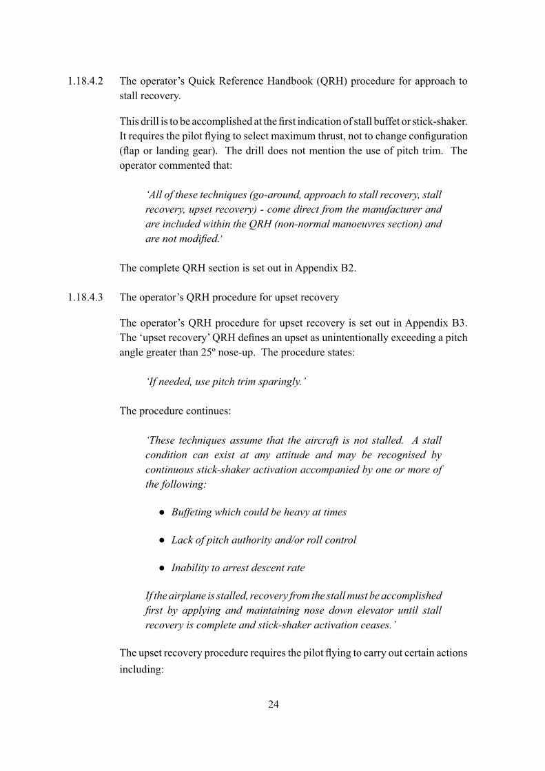
1.18.4.2 The operator’s Quick Reference Handbook (QRH) procedure for approach to stall recovery.
This drill is to be accomplished at the first indication of stall buffet or stick-shaker. It requires the pilot flying to select maximum thrust, not to change configuration (flap or landing gear). The drill does not mention the use of pitch trim. The operator commented that:
‘All of these techniques (go-around, approach to stall recovery, stall recovery, upset recovery) - come direct from the manufacturer and are included within the QRH (non-normal manoeuvres section) and are not modified.’
The complete QRH section is set out in Appendix B2.
1.18.4.3 The operator’s QRH procedure for upset recovery
The operator’s QRH procedure for upset recovery is set out in Appendix B3. The ‘upset recovery’ QRH defines an upset as unintentionally exceeding a pitch angle greater than 25º nose-up. The procedure states:
‘If needed, use pitch trim sparingly.’
The procedure continues:
‘These techniques assume that the aircraft is not stalled. A stall condition can exist at any attitude and may be recognised by continuous stick-shaker activation accompanied by one or more of the following:
Buffeting which could be heavy at times ●
Lack of pitch authority and/or roll control ●
Inability to arrest descent rate ●
If the airplane is stalled, recovery from the stall must be accomplished first by applying and maintaining nose down elevator until stall recovery is complete and stick-shaker activation ceases.’
The upset recovery procedure requires the pilot flying to carry out certain actions including:
25
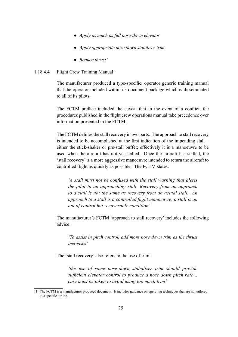
Apply as much as full nose-down elevator ●
Apply appropriate nose down stabilizer trim ●
Reduce thrust’ ●
1.18.4.4 Flight Crew Training Manual11
The manufacturer produced a type-specific, operator generic training manual that the operator included within its document package which is disseminated to all of its pilots.
The FCTM preface included the caveat that in the event of a conflict, the procedures published in the flight crew operations manual take precedence over information presented in the FCTM.
The FCTM defines the stall recovery in two parts. The approach to stall recovery is intended to be accomplished at the first indication of the impending stall – either the stick-shaker or pre-stall buffet; effectively it is a manoeuvre to be used when the aircraft has not yet stalled. Once the aircraft has stalled, the ‘stall recovery’ is a more aggressive manoeuvre intended to return the aircraft to controlled flight as quickly as possible. The FCTM states:
‘A stall must not be confused with the stall warning that alerts the pilot to an approaching stall. Recovery from an approach to a stall is not the same as recovery from an actual stall. An approach to a stall is a controlled flight manoeuvre, a stall is an out of control but recoverable condition’
The manufacturer’s FCTM ‘approach to stall recovery’ includes the following advice:
‘To assist in pitch control, add more nose down trim as the thrust increases’
The ‘stall recovery’ also refers to the use of trim:
‘the use of some nose-down stabalizer trim should provide sufficient elevator control to produce a nose down pitch rate…care must be taken to avoid using too much trim’
11 The FCTM is a manufacturer produced document. It includes guidance on operating techniques that are not tailored to a specific airline.
26
FCTM advice for upset recovery includes a section similar to the operator’s QRH regarding initially recovering from the stall. However, FCTM advice also states:
‘Under certain conditions, it may be necessary to reduce some thrust in order to prevent the angle of attack from continuing to increase.’
The FCTM goes on to say:
‘In a situation where the airplane pitch attitude is unintentionally more than 25 degrees nose high and increasing, the airspeed is decreasing rapidly. As airspeed decreases, the pilot’s ability to maneuver the airplane also decreases. If the stabilizer trim setting is nose up, as for slow-speed flight, it partially reduces the nose-down authority of the elevator. Further complicating this situation, as the airspeed decreases, the pilot could intuitively make a large thrust increase. This causes an additional pitch up. At full thrust settings and very low airspeeds, the elevator, working in opposition to the stabilizer, has limited control to reduce the pitch attitude.’
The full FCTM advice on stall recovery and upset recovery is set out in Appendix B4-7.
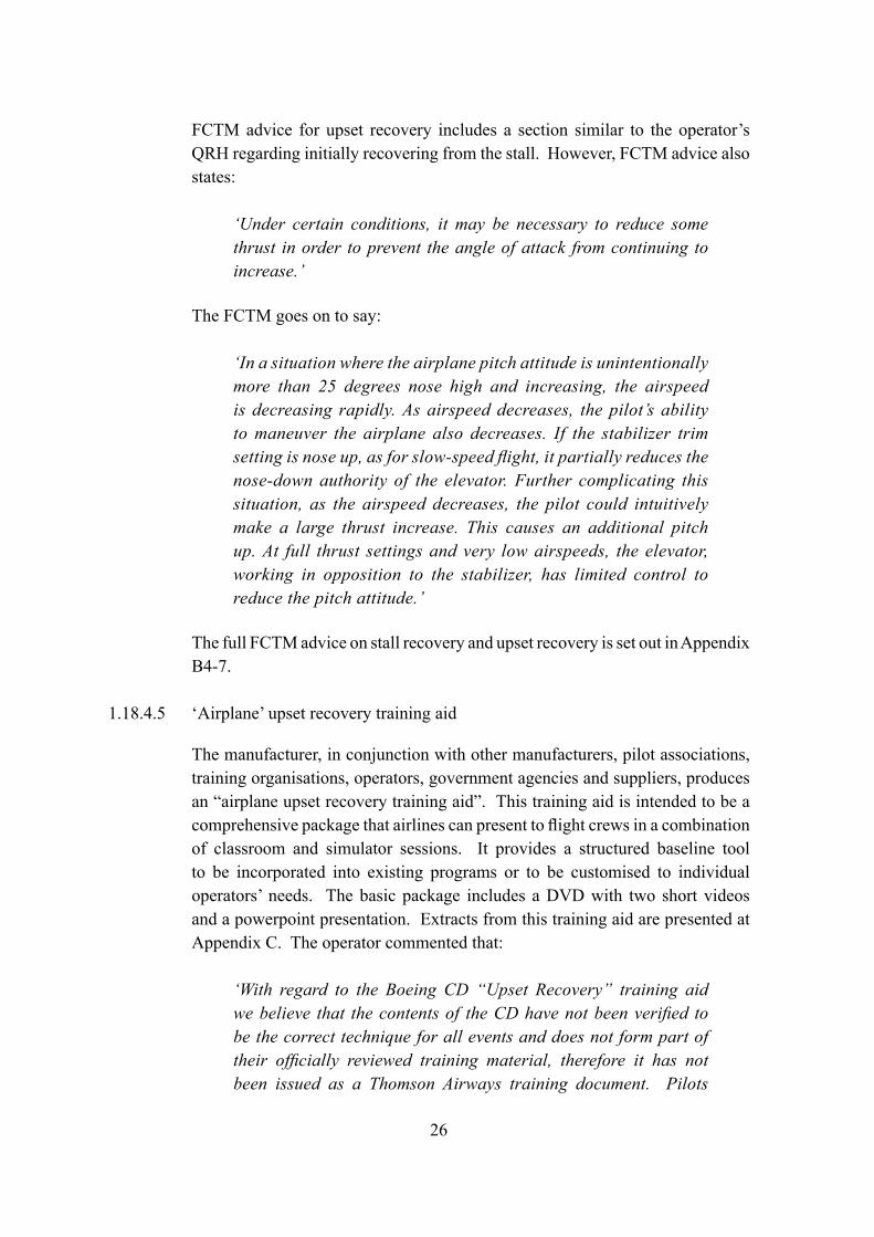
1.18.4.5 ‘Airplane’ upset recovery training aid
The manufacturer, in conjunction with other manufacturers, pilot associations, training organisations, operators, government agencies and suppliers, produces an “airplane upset recovery training aid”. This training aid is intended to be a comprehensive package that airlines can present to flight crews in a combination of classroom and simulator sessions. It provides a structured baseline tool to be incorporated into existing programs or to be customised to individual operators’ needs. The basic package includes a DVD with two short videos and a powerpoint presentation. Extracts from this training aid are presented at Appendix C. The operator commented that:
‘With regard to the Boeing CD “Upset Recovery” training aid we believe that the contents of the CD have not been verified to be the correct technique for all events and does not form part of their officially reviewed training material, therefore it has not been issued as a Thomson Airways training document. Pilots
27
are trained according to requirements in early recognition and counter measures on approaching stall in all configurations and recovery from full stall or after activation of stall warning device in all phases of flight, in all configurations.’
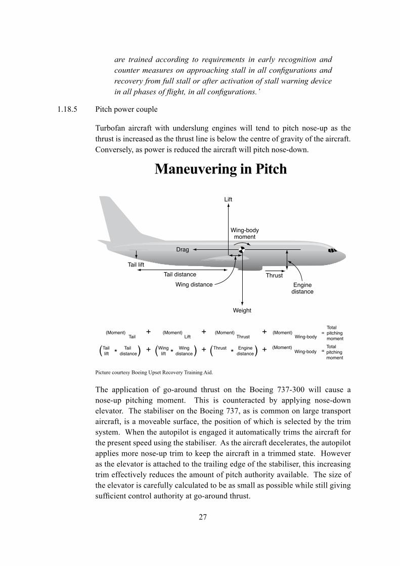
1.18.5 Pitch power couple
Turbofan aircraft with underslung engines will tend to pitch nose-up as the thrust is increased as the thrust line is below the centre of gravity of the aircraft. Conversely, as power is reduced the aircraft will pitch nose-down.
Picture courtesy Boeing Upset Recovery Training Aid.
The application of go-around thrust on the Boeing 737-300 will cause a nose-up pitching moment. This is counteracted by applying nose-down elevator. The stabiliser on the Boeing 737, as is common on large transport aircraft, is a moveable surface, the position of which is selected by the trim system. When the autopilot is engaged it automatically trims the aircraft for the present speed using the stabiliser. As the aircraft decelerates, the autopilot applies more nose-up trim to keep the aircraft in a trimmed state. However as the elevator is attached to the trailing edge of the stabiliser, this increasing trim effectively reduces the amount of pitch authority available. The size of the elevator is carefully calculated to be as small as possible while still giving sufficient control authority at go-around thrust.
Maneuvering in Pitch
Figure 3-B.47
Tail lift
Weight
Lift
Wing distance Enginedistance
ThrustTail distance
Drag
Wing-bodymoment
(Moment)Tail
(Moment)Lift
(Moment)Thrust
(Moment) =Wing-body
(Moment)Wing-body
Total
pitching
moment
=Total
pitching
moment
+ + +
+Tail Tail + +* * *lift
Wing Wing
distancelift distance
Thrust Engine
distance
28
The Boeing 737-300 engines are not thrust limited; if a pilot selects the thrust levers to the forward stop the engine will produce the maximum thrust available given the altitude and temperature. On days colder than standard12 this could be in excess of the maximum rated thrust of the engine. The N1 to generate rated thrust is automatically calculated and displayed on the N1 gauges; during a go-around pilots are expected to select that N1.
As the thrust increases during a go-around a large nose-up pitch couple is produced. This needs to be counteracted by nose-down elevator deflection to maintain level flight. If the elevator authority is reduced because of the amount of nose-up trim applied and the go-around thrust is greater than the rated thrust there may be insufficient elevator authority remaining to counteract the nose-up pitching moment.
12 International Standard Atmosphere Sea Level Temperature +15C Pressure 1013 millibars.
29
2 Analysis
2.1 Introduction
This serious incident occurred during a routine ILS approach at night in IMC. The investigation focussed on three areas: the incident itself, the operator’s response and a review of the efficacy of the autothrottle warning on the Boeing 737.
2.1.1 Autothrottle disengagement
The autothrottle disengaged during the approach. There are six possible conditions where the autothrottle system would disengage as detailed in paragraph 1.6.3 (page 10). The QAR information showed that there was no split between the thrust levers. The aircraft had not touched down. The crew did not report disconnecting the autothrottle at this stage and the QAR did not record a manual disconnect. The only condition that remained was an internal fault within the autothrottle computer.
The autothrottle system continued to operate normally on the subsequent approach and during flights following the incident. It was comprehensively tested on the aircraft and no faults were found. After removal from the aircraft the autothrottle computer did not pass the ATP. However, it was demonstrated that this fault would not necessarily have caused an in-flight disengagement of the autothrottle system.
An uncommanded disconnect, however, is not an unusual event. The analysis conducted on the OFDM data indicated that 0.4% of sectors flown had an autothrottle disconnect without any manual disconnect switch activity. The maintenance history on G-THOF’s autothrottle system recorded five defects in the nine months prior to this incident; in each case the system was checked with no fault found.
The autothrottle is a single-channel system. It is not required for flight operations on the Boeing 737-300 and the aircraft can be flown without the use of the autothrottle. The crew did not respond to the autothrottle’s disconnection either because the autothrottle warning did not work, or if it did work, the crew did not notice it. The recorded flight data shows the autothrottle warning as active; function testing could find no fault with the warning system. The subsequent event on 22 October and the other event discussed in 1.18 (page 21) showed that there may be a wider issue of the warning system not alerting flight crews.
30
The data gathering exercise carried out by the AAIB identified that 0.3% of Boeing 737 sectors had a combination of no recorded manual disconnection of the autothrottle and a warning lasting over nine seconds. The purpose of this limited study was to examine anecdotal and other information in order to establish the efficacy or otherwise of the autothrottle warning. The data gathering, although limited in scope, returned results which appear to justify the need for a much larger study of the autothrottle warning system on the Boeing 737. Therefore:
It is recommended that Boeing, in conjunction with the Federal Aviation Administration, conduct a study of the efficacy of the Boeing 737-300/400/500 autothrottle warning system and if necessary take steps to improve crew alerting. (Safety Recommendation 2009-043)
2.1.2 Disengagement alerting requirements
The autothrottle warning on G-THOF was typical of its era. Many later generation aircraft incorporate an autothrottle warning, including an audio alert, into an Engine Indication and Crew Alerting System (EICAS). Aircraft in general and automation technology specifically has advanced rapidly in reliability. Pilots familiar with operating older aircraft, which had more variable reliability, are nearing the end of their careers and there is a generation of pilots whose only experience is of operating aircraft with highly reliable automated systems. With this increasing reliability there is concern about flight crew encountering the issues outlined by the CAA paper 10/2004: that of a normally reliable system failing.
An illuminated warning should be distinct and gain the crew’s attention. The use of a multifunction caption whereby it flashes one colour (amber) for one reason and then another colour (red) for a different reason may reduce the crew’s awareness of the caption. The autothrottle warning on the Boeing 737-300 flashes amber routinely for extended periods during the approach phase of flight. It is likely that flight crews are subconsciously filtering out what is perceived as a nuisance message. This combined with the general high levels of reliability of modern automation could lead to a lack of awareness of autoflight modes.
The EASA Certification Standards (CS) set the standards for new aircraft designs. The current CS-25.1329 requirements treat autothrottle disconnection as a caution requiring immediate crew awareness but not immediate crew action as set out in 1.18.2. The regulators rationale for this was that although
31
the flight crew needs to be made continually aware of the autothrust system status, including disengagement, normal disengagement of the autothrust would not require immediate thrust control changes. A less specific indication, rather than a warning, is therefore allowable. The system fitted to the 737-300 would meet the current CS for a newly designed aircraft.
This incident, along with those in 1.18.1 (page 21) and the OFDM study highlight the limitations of the Boeing 737-300 alerting system despite it meeting current certification standards. Therefore:
It is recommended that The European Aviation Safety Agency review the requirements of Certification Standard 25 to ensure that the disengagement of autoflight controls, including autothrottle, is suitably alerted to flight crews. (Safety Recommendation 2009-044)
2.2 Crew reactions
Both pilots were qualified to operate the flight in accordance with company and national requirements. There is no reason to believe the crew’s performance was degraded by fatigue or for medical reasons. There is no evidence that the aircraft or flight crew were affected by any external factor during the approach. There also appears to be no technical failure of the autothrottle warnings or any of the aircraft’s engine or airspeed indications.
The aircraft was on target to be configured for landing by 1,400 ft aal, within the operator’s requirement to be stabilised1 by 1,000 ft aal, and there is no evidence that the crew were rushing the approach.
The use of flap 40 was not common for crews operating out of the Bournemouth base. The F/O needed to increase the brightness of his map light to ensure he was below the flap limiting speed for flap 40 before asking for it to be selected. This activity surrounding the selection of flap 40 was the only point where the reported flight deck activity appeared to vary from what was usual.
Regardless of the status of the autothrottle and its warnings, both pilots appear to have been distracted at a critical phase of flight. This lack of effective monitoring of automated systems allowed the aircraft to enter a low energy state following disconnection of the autothrottle.
1 Landing gear down, flaps in the landing position, on approach speed and engines spooled up.
32
The CAA funded studies by the Flight Operations Research Centre of Excellence (FORCE) at Cranfield University into flight crew performance and interaction with automated flight decks (section 1.18.3, page 23). It has completed its study phase and the report into its findings is expected to be available in the public domain in due course.
2.3 Aircraft pitch excursion
The go-around decision.
A go-around is a routine flight manoeuvre and flight crew are encouraged to go-around if an approach becomes unstable. When the captain reportedly took control, the aircraft was approximately 20 kt below the approach speed, decelerating with the thrust at or close to idle and fully configured for landing. The approach was unstable and action was required to recover the aircraft. The aircraft was on the verge of a stall warning and had the stall warning been active the commander should have carried out the ‘approach to stall recovery’ actions as a priority over the go-around. The evidence suggests that, at the time the commander made the decision to go-around, the stall warning was not active.
Go-around execution
The execution of a go-around involves both crew members carrying out specific tasks. The commander advanced the thrust levers to the forward limit of their travel. He called “GO-AROUND, FLAP 15 CHECK THRUST” and, in accordance with his training, applied forward column to counteract the expected nose-up pitch. When the commander took control, the F/O became the PM. It is the role of the PM to position the flap lever and adjust the N1.
Immediately after the go-around was commenced the stall warning activated. At this point responding to the stall warning became the highest priority, but the commander initiated a large increase in thrust as required by both the ‘approach to stall recovery’ and the ‘go-around’ procedures. The ‘approach to stall recovery’ calls for maximum thrust as opposed to ‘sufficient’ thrust for the go-around. The crew had maximum thrust selected. The commander attempted to control the pitch using the control column but, as shown by the manufacturer’s analysis, there was insufficient elevator authority available to counteract the thrust/pitch couple in the as-trimmed condition.
As the rate of pitch-up decayed briefly around 22º nose-up, the crew had maximum thrust selected. They had not yet changed configuration and were
33
adhering to the ‘approach to stall recovery’ drill. It is therefore probable that, whatever decision the commander made at the point he took control, the aircraft was going to pitch-up to at least 22º. The only way to avoid this would have been either to select a lower thrust setting or to trim forward during the thrust application.
Thrust
The operator’s ‘approach to stall recovery’ QRH drill requires the PF to ‘Advance thrust levers to maximum thrust’. Maximum is defined by the Oxford English dictionary as the ‘greatest amount possible.’ The ‘approach to stall recovery’ drill has to be an instinctive and straightforward drill and the technique of advancing the thrust levers to maximum meets these criteria. Unlike a go-around which can occur throughout the approach speed range, an ‘approach to stall recovery’ is only likely to occur with the aircraft in a low energy state. This drill makes no allowance for the pitch couple produced by the engines and the subsequent risk of the engine thrust overcoming the available elevator authority. A requirement to select less than maximum thrust may reduce the risk of an upset similar to the one in this incident but could result in too little thrust being used, increasing the risk of a stall. A technique that allows the use of maximum thrust while protecting the aircraft from the pitch couple is required.
Safety action taken by the manufacturer
Boeing stated that they:
‘recognise that there may be confusion with the wording of “maximum thrust” in the Approach to Stall Recovery procedure. The engine control system installed on the 737-600-900 (NG’s) are set so that in normal operation, selection of full forward thrust levers will result in a very small overboost and prevent exceedance of N1 and N2 rotor speeds. However the older control system of the 737 300-500 (Classics) will allow the engines to overboost if maximum thrust lever movement is selected. As such we plan to revise the definition of ‘maximum thrust’ for the Classic models to mean go-around or takeoff thrust unless ground contact is imminent.’
34
Trimming
Trimming is not mentioned in either the operator’s QRH ‘approach to stall recovery’ or the ‘go-around’ drills. In this incident the commander did not consider trimming the aircraft. The FCTM includes advice on trimming in both the ‘approach to stall recovery’ and the ‘stall recovery’ sections. This was available to both pilots but it is a generic document and not tailored to a particular airline. The company operations manuals, including the QRH, were the primary documents referred to by the flight crew for aircraft operation. Pilots are required to follow drills and procedures outlined in the operator’s QRH and deviation from these drills is discouraged. The FCTM itself states that in the event of a conflict, the procedures published in the flight crew operations manual take precedence over information presented in the FCTM. Therefore;
It is recommended that Boeing clarify the wording of the Boeing 737 300-500 approach to stall recovery Quick Reference Handbook Non-normal Manoeuvres to ensure that pilots are aware that trimming forward may be required to enhance pitch control authority. (Safety Recommendation 2009-045)
Flap retraction
Approximately 11 seconds after the thrust increased, the flaps were retracted to flap 15 even though the stall recovery checklist specifically states not to change the configuration. The manufacturer’s opinion is that on this occasion it made little difference to the outcome.
Upset recovery - general
Once the nose-up pitch angle exceeded 25º, the aircraft was outside the normal flying regime and an upset, as defined by the QRH, had occurred. At this stage, regardless of their initial actions, the crew needed to use ‘upset recovery’ techniques.
Upset recovery is defined in both the QRH and the FCTM. There is a caveat included:
‘if the airplane is stalled, recovery from the stall must be accomplished first by applying and maintaining nose down elevator until stall recovery is complete and stick-shaker activation ceases.’
35
The definition of a stall:
‘A stall condition..…may be recognized by continuous stick-shaker activation accompanied by one or more of the following:
• Buffeting which could be heavy at times• Lack of pitch authority and/or roll control• Inability to arrest descent rate…
Under certain conditions, it may be necessary to reduce some thrust in order to prevent the angle of attack from continuing to increase.’
By this definition the aircraft was recognisably stalled and the crew needed to effect a stall recovery.
Upset recovery - nose-high specific techniques
The first requirement of upset recovery is to recognise that the aircraft is in an upset condition as defined by the FCTM. For nose-high recovery the PF should apply as much as full nose-down elevator, appropriate stabiliser trim and reduce thrust.
Apart from holding the control column fully forward, the flight crew made no other pitch control actions throughout the 44º nose-up excursion until the aircraft had stalled and the nose had dropped towards the horizon. At this stage the thrust was reduced to go-around thrust. This thrust reduction allowed sufficient control authority to recover the aircraft and all three upset training documents include reducing thrust as one of their techniques. The techniques outlined in the manufacturer’s FCTM, the upset recovery training aid and the operator’s operations manual deal with this type of upset. Had these actions been carried out the aircraft was unlikely to have reached the extreme angles and speeds encountered and would have recovered to controlled flight sooner.
2.4 ASR
Company response
The initial reviewer decided not to file the ASR as an MOR. Although the ASR included a number of factors such that an MOR would have been appropriate, he decided to get more information from OFDM. This decision to seek additional information from the OFDM system was an optional
36
company procedure. However once the event passed out of sight of the safety department there was no process in place to ensure a timely follow-up of the incident. Although the company’s system would have provided a backstop of 30 days for the incident to be highlighted, there was a risk, borne out by this incident, that the processing of safety-critical information could be delayed between the two office locations.
The OFDM review policy was biased to dealing with ‘de-identified’ events where only a pilot representative reviewed the data. At the time of the incident the pilot representative workload did not allow for timely review of the data and when the 72 hour time limit for MOR submission was reached, there was no alert. When the next pilot representative came on duty 11 days after the event it was identified and appropriate action was taken.
There was no requirement for this incident to be de-identified. The commander had already filed an ASR and spoken with the safety department about the incident. The Schedule J, Appendix 2 agreement allowed for events that had been identified by ASR to be reviewed by an appropriate person and set out a process to facilitate this. Had the Schedule J, Appendix 2 process been followed it is likely that the severity of the event would have been captured within the MOR scheme time limits.
There were potential safety implications of the aircraft remaining in service for an extended period following this incident. The aircraft had operated outside the normal envelope although no damage had occurred. The flight crew operated additional sectors whilst expecting to be contacted regarding the incident. Had the severity of the incident been realised by the operator, the crew would have been suspended pending an investigation by the company.
Timeliness of OFDM analysis
OFDM as a mandatory activity is a relatively recent requirement. CAP 739 talks of batching data but also of ‘ideally’ reviewing data before the next flight. OFDM systems are valuable in the identification of trends in pilot handling and use this information to devise training programmes which improve standards across operators and the industry generally. A balance has to be struck between protecting the rights of the individual against unreasonable monitoring and the need to expedite data processing. Where an event has occurred and the pilots themselves have identified this, a rapid review of the data would seem appropriate.
37
2.5 The MOR Scheme
The ASR filed to the company by the captain stated ‘…..Speed decreased to 110 ……stick-shaker during initial part of G/A….’ Following the guidance of CAP 382 this would suggest that an MOR be filed under condition G (Go-around producing a hazardous or potentially hazardous situation.) The loss of at least 25 kt below the target speed of 135 kt should be reported under section H (Unintentional significant deviation from airspeed). The activation of the stick-shaker is covered by section X (Operation of any primary warning system associated with manoeuvring the aircraft eg config warning, stall warning (stick-shaker), over-speed warning etc.)
The search of the CAA MOR database showed that the operator had only filed two previous reports under the scheme for stick-shaker events in the five years prior to this incident. This contrasts with 11 ASRs received in the twelve months before this incident. The purpose of the MOR scheme is to collate statistical information to be used by regulators, designers and accident investigators. Significant under-reporting of events reduces the availability of safety trend analysis information to assist the industry to improve its safety standards. The step change in reporting levels from the operator following this incident is indicative that the company had reviewed its MOR submission policy throughout its organisation.
Safety action taken by the operator
Following the incident the operator conducted an internal review of the incident and their response to it. The following actions have been taken or are planned:
Pilot training
Additional training in general handling, specifically stalling and upset recovery has been added to the next set of simulator training. All pilots were due to have had this training by the end of June 2008. This stall recovery training included the possibility of using nose-down pitch trim during the recovery. The operator is trialling an eye position monitor for use during simulator training to determine where pilots are looking during critical phases of flight. Pilot information
The operator issued a number of operational notices to pilots highlighting the event and the need for vigilance in monitoring autoflight modes.
38
ASR and data handling
The operator moved its OFDM office to a secure office within the safety management team. This improved communication and integrated OFDM within the safety department while still protecting the flight crew from unreasonable monitoring.
The company also increased its establishment to two full-time data analysts and now has a pilot representative available in the data office daily.
The operator intends further investment to introduce an OFDM system that allows 24 hour access to certain functions by maintenance control to ensure continued airworthiness of aircraft involved in incidents. Its intention is to standardise its fleet on a telephone data link system such as was already installed on G-THOF at the time of this event.
General
The operator notified the AAIB of their intent of carrying out a general audit to review operational standards across all fleets by the end of 2008.
Operator comment
The operator commented that the commander should have telephoned the duty pilot manager as soon as he landed following the incident. While, in their view, the ASR system was robust and quick enough for routine events it is their belief that an event as serious as this should have been notified to the management by telephone immediately. The operator also commented that the initial ASR submitted by the commander did not accurately report the speed loss and did not address the degradation of pitch control. In the operator’s opinion, had either of the above procedures been followed, it would have prevented the issues surrounding the ASR processing.
39
3 Conclusions
3.1 Findings
Flight operations
1. The flight crew were properly licensed and qualified to conduct the flight. They were medically fit and there was no evidence of fatigue. Their training was in accordance with national regulations and the operator’s requirements.
2. The aircraft was certified, equipped and maintained in accordance with
existing regulations and approved procedures. At the time of the incident there were no recorded defects that might have contributed to the event.
3. The mass and centre of gravity of the aircraft were within the prescribed
limits.
4. The flight had been routine until the approach at Bournemouth.
5. The autothrottle retarded the thrust to idle in response to crew inputs.
6. The autothrottle disengaged for undetermined reasons.
7. No significant fault could be found with the autothrottle warning or associated systems.
8. The disengagement of the autothrottle was not recognised by the crew.
9. The aircraft’s Indicated Airspeed (IAS) decayed in line with crew expectations for an idle thrust approach and this constant deceleration approach masked the disengagement of the autothrottle.
10. No external factors degraded the flight crew’s ability to monitor the aircraft.
11. The pilots were distracted at a critical phase of flight and did not properly monitor the airspeed.
12. The aircraft stalled and descended in a nose-up attitude and slowed to a minimum airspeed of 82 kt.
40
13. The thrust levers remained at full thrust for 26 seconds and N1 exceeded the target N1 for 31 seconds.
14. The flaps retraction did not materially affect the event.
15. The stall recovery techniques recommended in the manufacturer’s Flight Crew Training Manual (FCTM) were not fully applied.
16. Forward trim was not used during the stall recovery.
17. A reduction in thrust lever position to a go-around (GA) thrust setting occurred 40 seconds after the go-around was initiated, which allowed sufficient nose-down elevator authority to control the pitch-up couple.
18. The speeds and pitch angles were outside the flight test envelope and outside the validated flight modelling envelope.
Flight procedures
1. The wording of the go-around drill in the Quick Reference Handbook (QRH) has the potential to prejudice pilots away from reducing thrust to match the required go-around thrust.
2. The ‘go-around’ drill and ‘approach to stall’ drill in the QRH do not mention trimming the aircraft.
3. The upset recovery techniques outlined in the QRH, FCTM and the manufacturer’s training aid are effective and would have resulted in earlier recovery of the aircraft.
Safety management
1. The Air Safety Report (ASR) as filed by the commander did not depict the event accurately.
2. The ASR was received at the operator’s offices the morning after the event but was not initially filed as an Mandatory Occurrence Report (MOR).
3. The ASR was passed to the Operational Flight Data Monitoring (OFDM) analyst on the day after the event and was reviewed that day when the OFDM analyst flagged the event for a pilot representative.
41
4. The flight data was not viewed by a pilot representative until 11 days after the event. This delay in reviewing the data resulted in the loss of information of value to the investigation.
5. The delay in reviewing the data allowed both the aircraft and the crew to continue operating without the incident being reviewed.
6. There was no requirement in the company OFDM agreement to de-identify the data and the data could have been reviewed on the day after the event.
7. The operator has undertaken significant changes in their OFDM and safety
management system following this event.
3.2 Causal factors
The investigation identified the following causal factors:
1. The aircraft decelerated during an instrument approach, to an airspeed significantly below the commanded speed, with the engines at idle thrust. Despite the application of full thrust, the aircraft stalled, after which the appropriate recovery actions were not followed.
2. The trimmed position of the stabiliser, combined with the selection of maximum thrust, overwhelmed the available elevator authority.
3.3 Contributory factors
The investigation identified the following contributory factors:
1. The autothrottle warning system on the Boeing 737-300, although working as designed, did not alert the crew to the disengagement of the autothrottle system.
2. The flight crew did not recognise the disengagement of the autothrottle system and allowed the airspeed to decrease 20 kt below VREF before recovery was initiated.
42
4 Safety Recommendations
4.1 Safety Recommendation 2009-043: It is recommended that Boeing, in conjunction with the Federal Aviation Administration, conduct a study of the efficacy of the Boeing 737-300/400/500 autothrottle warning and if necessary take steps to improve crew alerting.
4.2 Safety Recommendation 2009-044: It is recommended that The European Aviation Safety Agency review the requirements of Certification Standard 25 to ensure that the disengagement of autoflight controls including autothrottle is suitably alerted to flightcrews.
4.3 Safety Recommendation 2009-045: It is recommended that Boeing clarify the wording of the approach to stall recovery Quick Reference Handbook Non-normal Manoeuvres to ensure that pilots are aware that trimming forward may be required to enhance pitch control authority.
K ConradiPrincipal Inspector of Air AccidentsAir Accidents Investigation BranchDepartment for TransportApril 2009
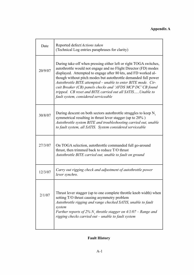
A-1
Appendix A
Date Reported defect/Actions taken(Technical Log entries paraphrases for clarity)
20/9/07
During take-off when pressing either left or right TOGA switches, autothrottle would not engage and no Flight Director (FD) modes displayed. Attempted to engage after 80 kts, and FD worked al-though without pitch modes but autothrottle demanded full powerAutothrottle BITE attempted – unable to enter BITE mode. Cir-cuit Breaker (CB) panels checks and ‘AFDS MCP DC’ CB found tripped. CB reset and BITE carried out all SATIS…..Unable to fault system, considered serviceable
30/8/07 During descent on both sectors autothrottle struggles to keep N1 symmetrical resulting in thrust lever stagger (up to 20% )Autothrottle system BITE and troubleshooting carried out, unable to fault system, all SATIS. System considered serviceable
27/3/07 On TOGA selection, autothrottle commanded full go-around thrust, then trimmed back to reduce T/O thrustAutothrottle BITE carried out, unable to fault on ground
12/3/07 Carry out rigging check and adjustment of autothrottle power lever synchro.
2/1/07 Thrust lever stagger (up to one complete throttle knob width) when setting T/O thrust causing asymmetry problemAutothrottle rigging and range checked SATIS, unable to fault systemFurther reports of 2% N1 throttle stagger on 4/1/07 – Range and rigging checks carried out – unable to fault system
Fault History
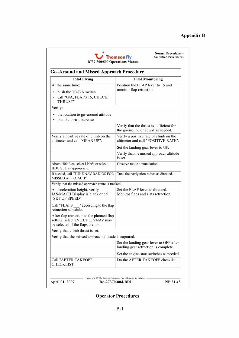
B-1
Appendix B
Normal Procedures -
Amplified Procedures
Copyright © The Boeing Company. See title page for details.
D6-27370-804-BRI NP.21.43
B737-300/500 Operations Manual
Go–Around and Missed Approach Procedure
Pilot Flying Pilot Monitoring
At the same time:
• push the TO/GA switch
• call "G/A, FLAPS 15, CHECK THRUST"
Position the FLAP lever to 15 and monitor flap retraction
Verify:
• the rotation to go–around attitude
• that the thrust increases
Verify that the thrust is sufficient for the go-around or adjust as needed.
Verify a positive rate of climb on the altimeter and call "GEAR UP".
Verify a positive rate of climb on the altimeter and call "POSITIVE RATE".
Set the landing gear lever to UP.
Verify that the missed approach altitude is set.
Above 400 feet, select LNAV or select
HDG SEL as appropriate.
Observe mode annunciation.
If needed, call "TUNE NAV RADIOS FOR
MISSED APPROACH".
Tune the navigation radios as directed.
Verify that the missed approach route is tracked.
At acceleration height, verify IAS/MACH Display is blank or call "SET UP SPEED".
Call "FLAPS ___" according to the flap retraction schedule.
Set the FLAP lever as directed. Monitor flaps and slats retraction.
After flap retraction to the planned flap setting, select LVL CHG. VNAV may be selected if the flaps are up.
Verify that climb thrust is set.
Verify that the missed approach altitude is captured.
Set the landing gear lever to OFF after landing gear retraction is complete.
Set the engine start switches as needed.
Call "AFTER TAKEOFF CHECKLIST"
Do the AFTER TAKEOFF checklist.
April 01, 2007
Operator Procedures
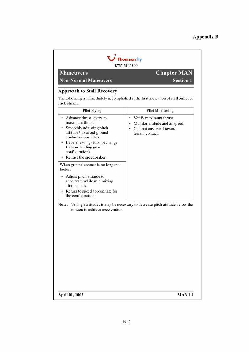
B-2
Appendix B
B737-300/-500
Maneuvers Chapter MAN
Non-Normal Maneuvers Section 1
MAN.1.1
MAN.1 Maneuvers-Non-Normal ManeuversApproach to Stall Recovery
The following is immediately accomplished at the first indication of stall buffet or
stick shaker.
Note: *At high altitudes it may be necessary to decrease pitch attitude below the
horizon to achieve acceleration.
Pilot Flying Pilot Monitoring
• Advance thrust levers to maximum thrust.
• Smoothly adjusting pitch attitude* to avoid ground contact or obstacles.
• Level the wings (do not change flaps or landing gear configuration).
• Retract the speedbrakes.
• Verify maximum thrust.
• Monitor altitude and airspeed.
• Call out any trend toward terrain contact.
When ground contact is no longer a factor:
• Adjust pitch attitude to accelerate while minimizing altitude loss.
• Return to speed appropriate for the configuration.
April 01, 2007
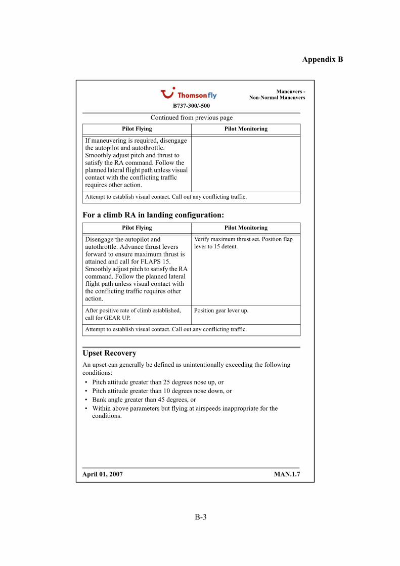
B-3
Appendix B
B737-300/-500
Maneuvers -
Non-Normal Maneuvers
MAN.1.7
Continued from previous page
For a climb RA in landing configuration:
Upset Recovery
An upset can generally be defined as unintentionally exceeding the following
conditions:
• Pitch attitude greater than 25 degrees nose up, or
• Pitch attitude greater than 10 degrees nose down, or
• Bank angle greater than 45 degrees, or
• Within above parameters but flying at airspeeds inappropriate for the conditions.
Pilot Flying Pilot Monitoring
If maneuvering is required, disengage the autopilot and autothrottle. Smoothly adjust pitch and thrust to satisfy the RA command. Follow the planned lateral flight path unless visual contact with the conflicting traffic requires other action.
Attempt to establish visual contact. Call out any conflicting traffic.
Pilot Flying Pilot Monitoring
Disengage the autopilot and autothrottle. Advance thrust levers forward to ensure maximum thrust is attained and call for FLAPS 15. Smoothly adjust pitch to satisfy the RA command. Follow the planned lateral flight path unless visual contact with the conflicting traffic requires other action.
Verify maximum thrust set. Position flap
lever to 15 detent.
After positive rate of climb established,
call for GEAR UP.
Position gear lever up.
Attempt to establish visual contact. Call out any conflicting traffic.
April 01, 2007
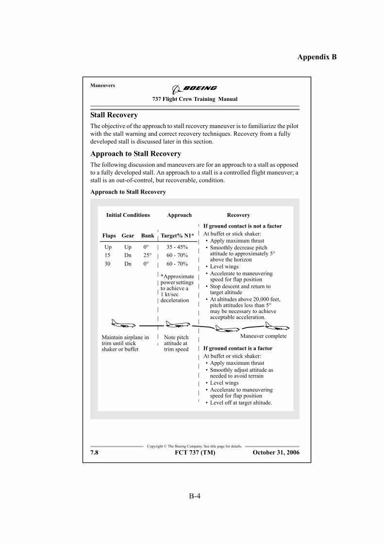
B-4
Appendix B
737 Flight Crew Training Manual
Maneuvers
Copyright © The Boeing Company. See title page for details.
7.8 FCT 737 (TM)
Stall Recovery
The objective of the approach to stall recovery maneuver is to familiarize the pilot
with the stall warning and correct recovery techniques. Recovery from a fully
developed stall is discussed later in this section.
Approach to Stall Recovery
The following discussion and maneuvers are for an approach to a stall as opposed
to a fully developed stall. An approach to a stall is a controlled flight maneuver; a
stall is an out-of-control, but recoverable, condition.
Approach to Stall Recovery
*Approximate power settings to achieve a 1 kt/sec deceleration
If ground contact is not a factor
At buffet or stick shaker:
• Apply maximum thrust
• Smoothly decrease pitch attitude to approximately 5° above the horizon
• Level wings
• Accelerate to maneuvering speed for flap position
• Stop descent and return to target altitude
• At altitudes above 20,000 feet, pitch attitudes less than 5° may be necessary to achieve acceptable acceleration.
Target% N1*GearFlaps Bank
Maneuver complete
Initial Conditions Approach Recovery
Note pitch attitude at trim speed
Up Up
Dn
Dn
15
30
0°
25°
0°
35 - 45%
60 - 70%
60 - 70%
Maintain airplane in trim until stick shaker or buffet If ground contact is a factor
At buffet or stick shaker:
• Apply maximum thrust
• Smoothly adjust attitude as needed to avoid terrain
• Level wings
• Accelerate to maneuvering speed for flap position
• Level off at target altitude.
October 31, 2006
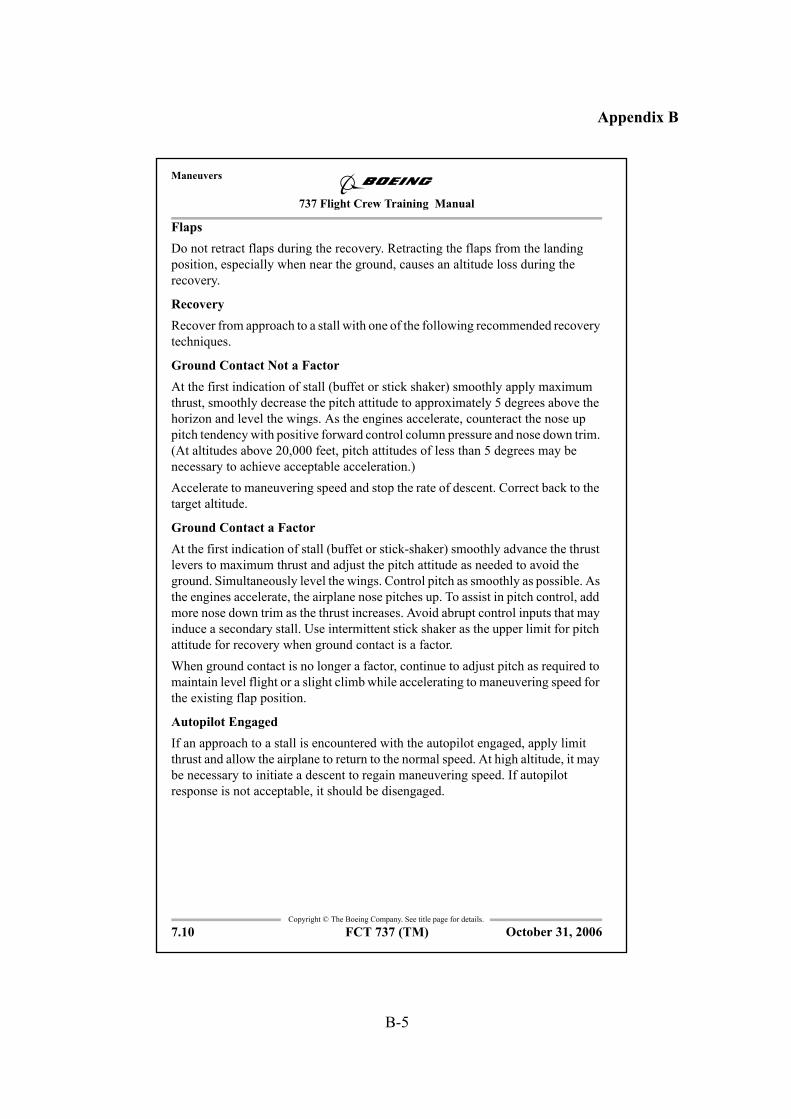
B-5
Appendix B
737 Flight Crew Training Manual
Maneuvers
Copyright © The Boeing Company. See title page for details.
7.10 FCT 737 (TM)
Flaps
Do not retract flaps during the recovery. Retracting the flaps from the landing
position, especially when near the ground, causes an altitude loss during the
recovery.
Recovery
Recover from approach to a stall with one of the following recommended recovery
techniques.
Ground Contact Not a Factor
At the first indication of stall (buffet or stick shaker) smoothly apply maximum
thrust, smoothly decrease the pitch attitude to approximately 5 degrees above the
horizon and level the wings. As the engines accelerate, counteract the nose up
pitch tendency with positive forward control column pressure and nose down trim.
(At altitudes above 20,000 feet, pitch attitudes of less than 5 degrees may be
necessary to achieve acceptable acceleration.)
Accelerate to maneuvering speed and stop the rate of descent. Correct back to the
target altitude.
Ground Contact a Factor
At the first indication of stall (buffet or stick-shaker) smoothly advance the thrust
levers to maximum thrust and adjust the pitch attitude as needed to avoid the
ground. Simultaneously level the wings. Control pitch as smoothly as possible. As
the engines accelerate, the airplane nose pitches up. To assist in pitch control, add
more nose down trim as the thrust increases. Avoid abrupt control inputs that may
induce a secondary stall. Use intermittent stick shaker as the upper limit for pitch
attitude for recovery when ground contact is a factor.
When ground contact is no longer a factor, continue to adjust pitch as required to
maintain level flight or a slight climb while accelerating to maneuvering speed for
the existing flap position.
Autopilot Engaged
If an approach to a stall is encountered with the autopilot engaged, apply limit
thrust and allow the airplane to return to the normal speed. At high altitude, it may
be necessary to initiate a descent to regain maneuvering speed. If autopilot
response is not acceptable, it should be disengaged.
October 31, 2006
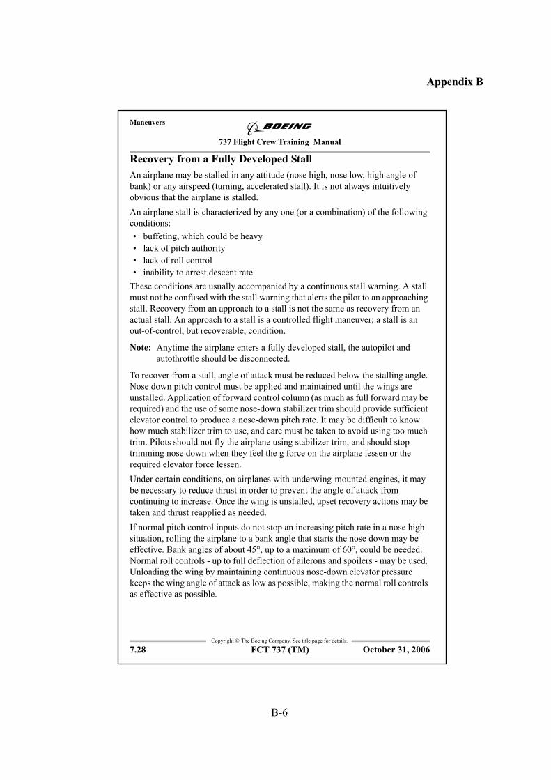
B-6
Appendix B
737 Flight Crew Training Manual
Maneuvers
Copyright © The Boeing Company. See title page for details.
7.28 FCT 737 (TM)
Recovery from a Fully Developed Stall
An airplane may be stalled in any attitude (nose high, nose low, high angle of
bank) or any airspeed (turning, accelerated stall). It is not always intuitively
obvious that the airplane is stalled.
An airplane stall is characterized by any one (or a combination) of the following
conditions:
• buffeting, which could be heavy
• lack of pitch authority
• lack of roll control
• inability to arrest descent rate.
These conditions are usually accompanied by a continuous stall warning. A stall
must not be confused with the stall warning that alerts the pilot to an approaching
stall. Recovery from an approach to a stall is not the same as recovery from an
actual stall. An approach to a stall is a controlled flight maneuver; a stall is an
out-of-control, but recoverable, condition.
Note: Anytime the airplane enters a fully developed stall, the autopilot and
autothrottle should be disconnected.
To recover from a stall, angle of attack must be reduced below the stalling angle.
Nose down pitch control must be applied and maintained until the wings are
unstalled. Application of forward control column (as much as full forward may be
required) and the use of some nose-down stabilizer trim should provide sufficient
elevator control to produce a nose-down pitch rate. It may be difficult to know
how much stabilizer trim to use, and care must be taken to avoid using too much
trim. Pilots should not fly the airplane using stabilizer trim, and should stop
trimming nose down when they feel the g force on the airplane lessen or the
required elevator force lessen.
Under certain conditions, on airplanes with underwing-mounted engines, it may
be necessary to reduce thrust in order to prevent the angle of attack from
continuing to increase. Once the wing is unstalled, upset recovery actions may be
taken and thrust reapplied as needed.
If normal pitch control inputs do not stop an increasing pitch rate in a nose high
situation, rolling the airplane to a bank angle that starts the nose down may be
effective. Bank angles of about 45°, up to a maximum of 60°, could be needed.
Normal roll controls - up to full deflection of ailerons and spoilers - may be used.
Unloading the wing by maintaining continuous nose-down elevator pressure
keeps the wing angle of attack as low as possible, making the normal roll controls
as effective as possible.
October 31, 2006
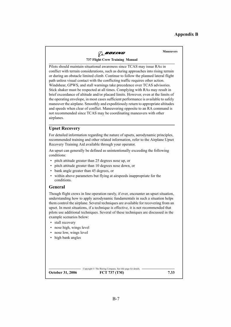
B-7
Appendix B
737 Flight Crew Training Manual
Maneuvers
Copyright © The Boeing Company. See title page for details.
FCT 737 (TM) 7.33
Pilots should maintain situational awareness since TCAS may issue RAs in
conflict with terrain considerations, such as during approaches into rising terrain
or during an obstacle limited climb. Continue to follow the planned lateral flight
path unless visual contact with the conflicting traffic requires other action.
Windshear, GPWS, and stall warnings take precedence over TCAS advisories.
Stick shaker must be respected at all times. Complying with RAs may result in
brief exceedance of altitude and/or placard limits. However, even at the limits of
the operating envelope, in most cases sufficient performance is available to safely
maneuver the airplane. Smoothly and expeditiously return to appropriate altitudes
and speeds when clear of conflict. Maneuvering opposite to an RA command is
not recommended since TCAS may be coordinating maneuvers with other
airplanes.
Upset Recovery
For detailed information regarding the nature of upsets, aerodynamic principles,
recommended training and other related information, refer to the Airplane Upset
Recovery Training Aid available through your operator.
An upset can generally be defined as unintentionally exceeding the following
conditions:
• pitch attitude greater than 25 degrees nose up, or
• pitch attitude greater than 10 degrees nose down, or
• bank angle greater than 45 degrees, or
• within above parameters but flying at airspeeds inappropriate for the conditions.
General
Though flight crews in line operation rarely, if ever, encounter an upset situation,
understanding how to apply aerodynamic fundamentals in such a situation helps
them control the airplane. Several techniques are available for recovering from an
upset. In most situations, if a technique is effective, it is not recommended that
pilots use additional techniques. Several of these techniques are discussed in the
example scenarios below:
• stall recovery
• nose high, wings level
• nose low, wings level
• high bank angles
October 31, 2006
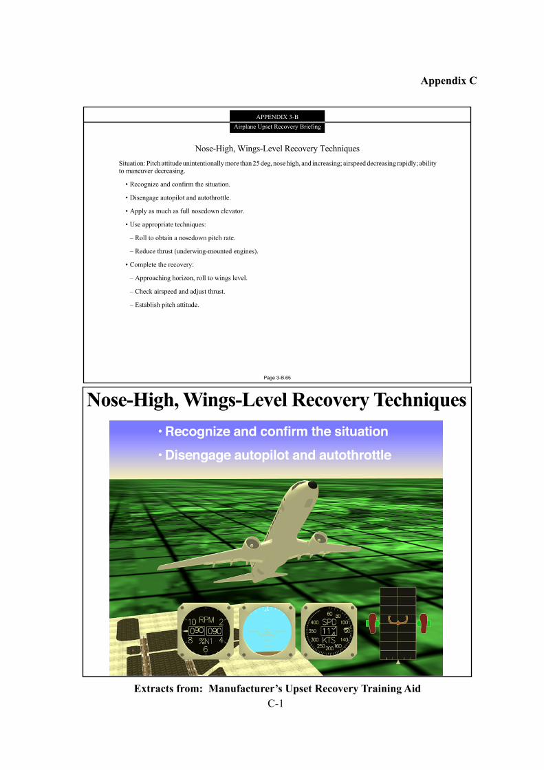
C-1
Appendix C
APPENDIX 3-B
Airplane Upset Recovery Briefing
Nose-High, Wings-Level Recovery Techniques
Situation: Pitch attitude unintentionally more than 25 deg, nose high, and increasing; airspeed decreasing rapidly; abilityto maneuver decreasing.
• Recognize and confirm the situation.
• Disengage autopilot and autothrottle.
• Apply as much as full nosedown elevator.
• Use appropriate techniques:
– Roll to obtain a nosedown pitch rate.
– Reduce thrust (underwing-mounted engines).
• Complete the recovery:
– Approaching horizon, roll to wings level.
– Check airspeed and adjust thrust.
– Establish pitch attitude.
Page 3-B.65
Nose-High, Wings-Level Recovery Techniques
• Recognize and confirm the situation
• Disengage autopilot and autothrottle
Figure 3-B.65Extracts from: Manufacturer’s Upset Recovery Training Aid
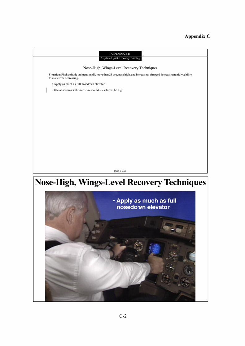
C-2
Appendix C
APPENDIX 3-B
Airplane Upset Recovery Briefing
Nose-High, Wings-Level Recovery Techniques
Situation: Pitch attitude unintentionally more than 25 deg, nose high, and increasing; airspeed decreasing rapidly; abilityto maneuver decreasing.
• Apply as much as full nosedown elevator.
• Use nosedown stabilizer trim should stick forces be high.
Page 3-B.66
Nose-High, Wings-Level Recovery Techniques
• Apply as much as fullnosedown elevator
Figure 3-B.66
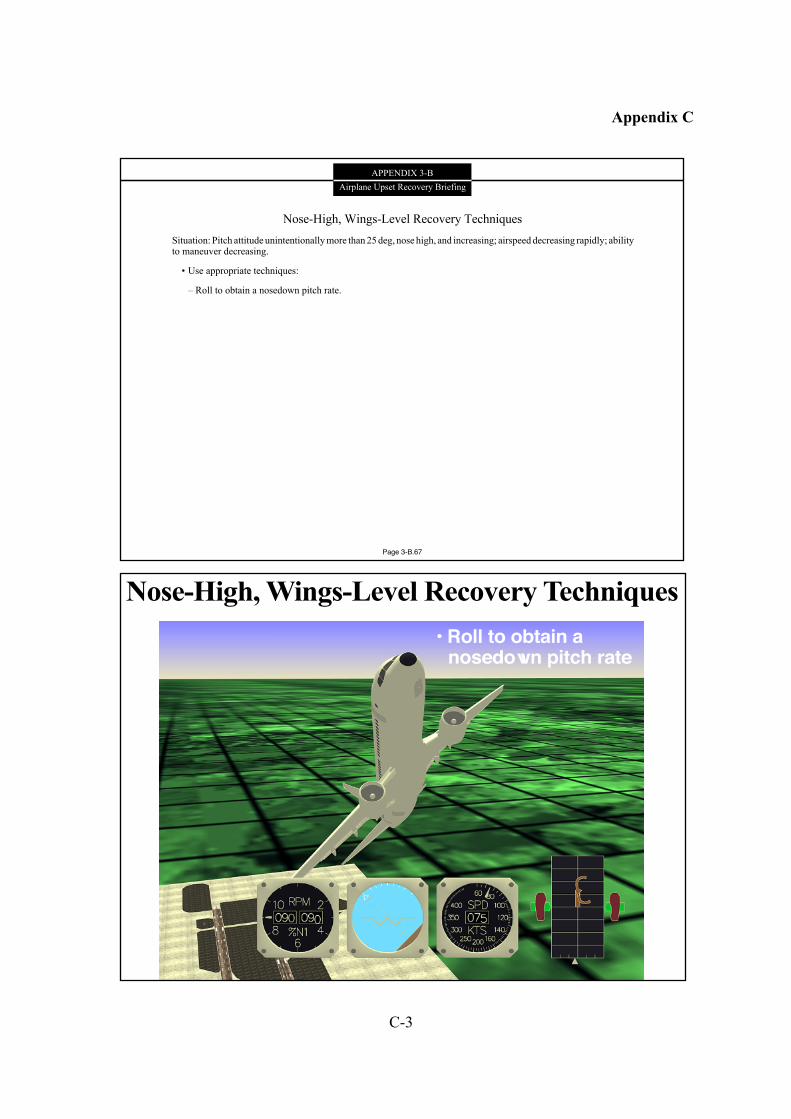
C-3
Appendix C
APPENDIX 3-B
Airplane Upset Recovery Briefing
Nose-High, Wings-Level Recovery Techniques
Situation: Pitch attitude unintentionally more than 25 deg, nose high, and increasing; airspeed decreasing rapidly; abilityto maneuver decreasing.
• Use appropriate techniques:
– Roll to obtain a nosedown pitch rate.
Page 3-B.67
Nose-High, Wings-Level Recovery Techniques
• Roll to obtain anosedown pitch rate
Figure 3-B.67
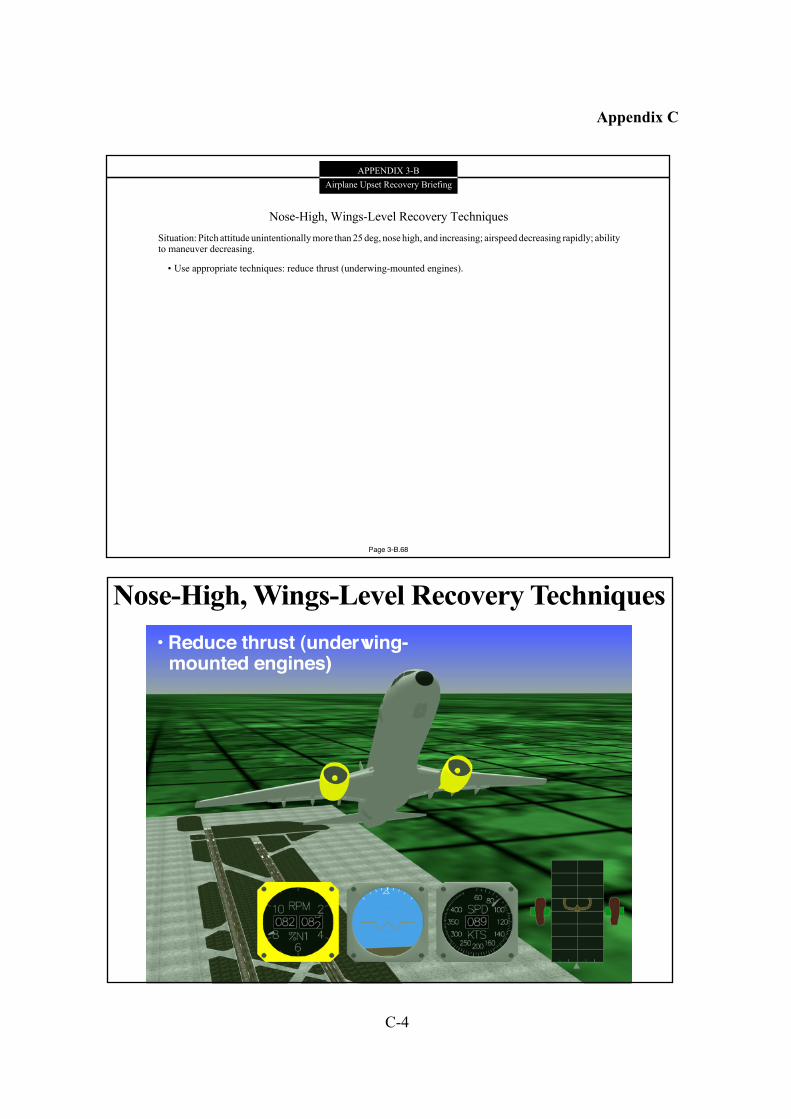
C-4
Appendix C
APPENDIX 3-B
Airplane Upset Recovery Briefing
Nose-High, Wings-Level Recovery Techniques
Situation: Pitch attitude unintentionally more than 25 deg, nose high, and increasing; airspeed decreasing rapidly; abilityto maneuver decreasing.
• Use appropriate techniques: reduce thrust (underwing-mounted engines).
Page 3-B.68
Nose-High, Wings-Level Recovery Techniques
• Reduce thrust (underwing-mounted engines)
Figure 3-B.68
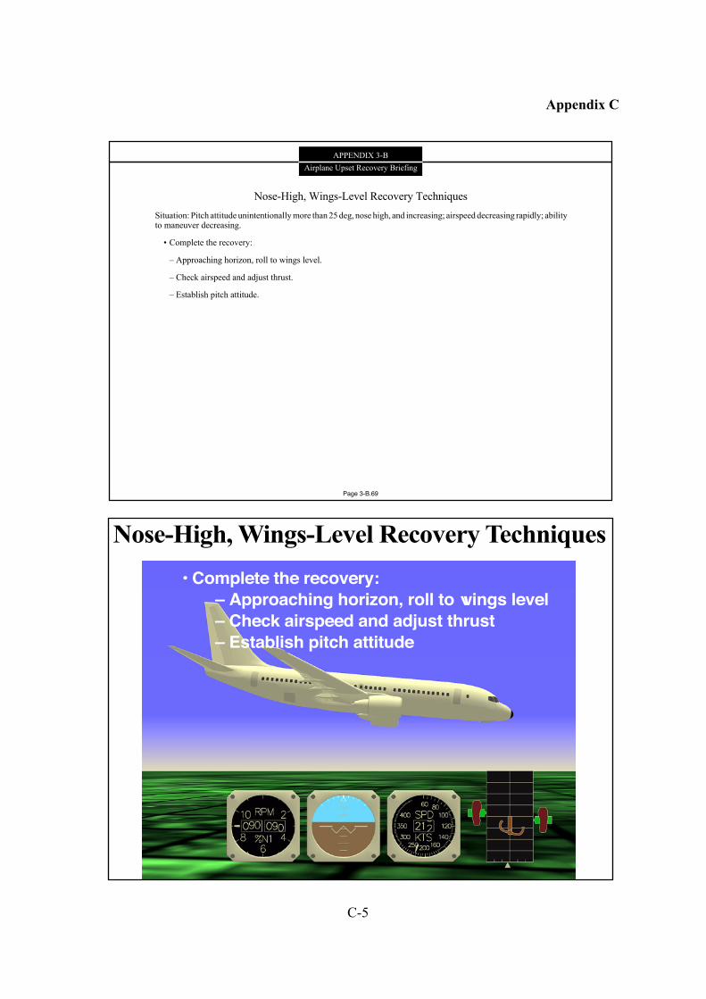
C-5
Appendix C
APPENDIX 3-B
Airplane Upset Recovery Briefing
Nose-High, Wings-Level Recovery Techniques
Situation: Pitch attitude unintentionally more than 25 deg, nose high, and increasing; airspeed decreasing rapidly; abilityto maneuver decreasing.
• Complete the recovery:
– Approaching horizon, roll to wings level.
– Check airspeed and adjust thrust.
– Establish pitch attitude.
Page 3-B.69
Nose-High, Wings-Level Recovery Techniques
• Complete the recovery:
– Approaching horizon, roll to wings level
– Check airspeed and adjust thrust
– Establish pitch attitude
Figure 3-B.69
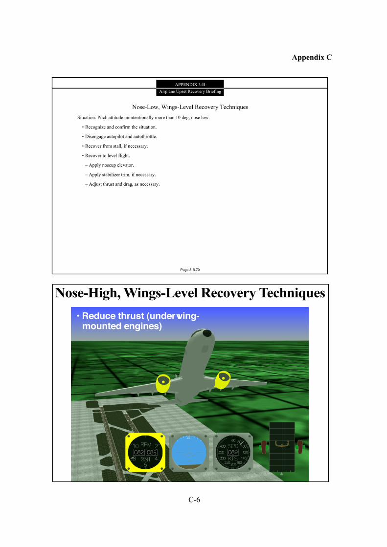
C-6
Appendix C
APPENDIX 3-B
Airplane Upset Recovery Briefing
Nose-Low, Wings-Level Recovery Techniques
Situation: Pitch attitude unintentionally more than 10 deg, nose low.
• Recognize and confirm the situation.
• Disengage autopilot and autothrottle.
• Recover from stall, if necessary.
• Recover to level flight.
– Apply noseup elevator.
– Apply stabilizer trim, if necessary.
– Adjust thrust and drag, as necessary.
Page 3-B.70
Nose-High, Wings-Level Recovery Techniques
• Reduce thrust (underwing-mounted engines)
Figure 3-B.68