Embed Size (px)
Citation preview
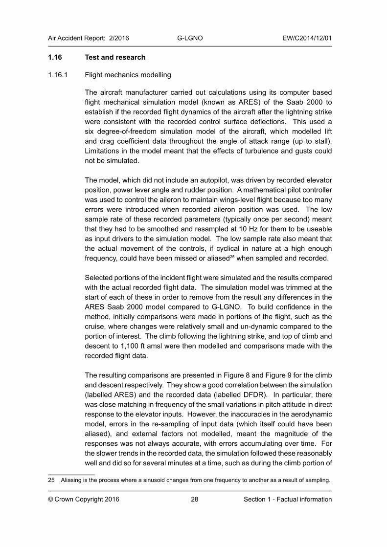
AIRCRAFT ACCIDENT REPORT 2/2016
Report on the serious incident toSaab 2000, G-LGNO
Approximately 7 nm east of Sumburgh Airport, Shetland15 December 2014
AAIBAir Accidents Investigation Branch

Unless otherwise indicated, recommendations in this report are addressed to the appropriate regulatory authorities having responsibility for the matters with which the recommendation is concerned. It is for those authorities to decide what action is taken. In the United Kingdom the responsible authority is the Civil Aviation Authority, CAA House, 45-49 Kingsway, London WC2B 6TE or the European Aviation Safety Agency, Postfach 10 12 53, D-50452 Koeln, Germany.
AIRCRAFT ACCIDENT REPORT 2/2016
Air Accidents Investigation Branch
Report on the serious incident toSaab 2000, G-LGNO
Approximately 7 nm east of Sumburgh Airport, Shetland15 December 2014
This investigation has been conducted in accordance with Annex 13 to the ICAO Convention on International Civil Aviation,
EU Regulation No 996/2010 and The Civil Aviation (Investigation of Air Accidents and Incidents) Regulations 1996.
The sole objective of the investigation of an accident or incident under these Regulations is the prevention of future accidents and incidents. It is not the purpose of such
an investigation to apportion blame or liability.
Accordingly, it is inappropriate that AAIB reports should be used to assign fault or blame or determine liability, since neither the investigation nor the reporting process has been
undertaken for that purpose.
ii
© Crown Copyright 2016
Printed in the United Kingdom for the Air Accidents Investigation Branch
This report contains facts which have been determined up to the time of publication. This information is published to inform the aviation industry and the public of the general circumstances of accidents and serious incidents.
Extracts may be published without specific permission providing that the source is duly acknowledged, the material is reproduced accurately and it is not used in a derogatory manner or in a misleading context.
Published 6 September 2016
iii© Crown Copyright 2016
Department for TransportAir Accidents Investigation BranchFarnborough HouseBerkshire Copse RoadAldershotHampshire GU11 2HH
August 2016
The Right Honourable Chris Grayling Secretary of State for Transport
Dear Secretary of State
I have the honour to submit the report on the circumstances of the serious incident to Saab 2000, registration G-LGNO, approximately 7 nm east of Sumburgh Airport, Shetland on 15 December 2014.
Yours sincerely
Keith ConradiChief Inspector of Air Accidents

Intentionally left blank
v
Air Accident Report: 2/2016 G-LGNO EW/C2014/12/01
© Crown Copyright 2016 Contents
Contents
Summary .......................................................................................................................... 1
1 Factual Information ................................................................................................ 31.1 History of the flight .......................................................................................... 3
1.1.1 Flight crew recollection of the event .................................................. 6
1.2 Injuries to persons ........................................................................................... 6
1.3 Damage to the aircraft .................................................................................... 7
1.4 Other damage ................................................................................................. 7
1.5 Personnel Information ..................................................................................... 71.5.1 Commander ...................................................................................... 71.5.2 Co-pilot .............................................................................................. 71.5.3 Flight crew information ...................................................................... 8
1.6 Aircraft Information .......................................................................................... 91.6.1 General information .......................................................................... 91.6.2 Flight envelope .................................................................................. 91.6.3 Flight control system ....................................................................... 101.6.4 Autopilot system ...............................................................................111.6.5 Air Data Computer system .............................................................. 141.6.6 Maintenance history ........................................................................ 141.6.7 Autopilot system requirements for initial Saab 2000 certification .... 15
1.6.7.1 Current requirements.................................................... 151.6.7.2 EASA and FAA interpretation on whether the Saab 2000 would meet the current 25.1329(l) requirements ......... 191.6.7.3 Design rationale for the Saab 2000 autopilot system during flight crew override ............................................ 19
1.6.8 Aircraft examination ........................................................................ 20
1.7 Meteorological information ............................................................................ 211.7.1 Conditions in flight ........................................................................... 211.7.2 Handbook of Aviation Meteorology ................................................. 211.7.3 Triggered lightning .......................................................................... 211.7.4 Saab 2000 and Saab 340 response to lightning strikes .................. 221.7.5 Instructions and information provided to flight crew concerning lightning strikes ............................................................................... 22
1.8 Aids to navigation .......................................................................................... 22
1.9 Communications ........................................................................................... 22
1.10 Aerodrome information ................................................................................. 22
1.11 Flight recorders ............................................................................................. 231.11.1 Cockpit voice recorder .................................................................... 231.11.2 Flight data recorder ......................................................................... 23
vi
Air Accident Report: 2/2016 G-LGNO EW/C2014/12/01
© Crown Copyright 2016 Contents
1.12 Wreckage and impact information ................................................................ 27
1.13 Medical and pathological information ............................................................ 27
1.14 Fire ................................................................................................................ 27
1.15 Survival aspects ............................................................................................ 27
1.16 Test and research ......................................................................................... 281.16.1 Flight mechanics modelling ............................................................. 281.16.2 Crew override effects on autopilot systems on other commercial aircraft types ................................................................................... 311.16.3 Previous occurrences involving flight crew override of the autopilot ..35
1.16.3.1 Accident to Airbus A300, registration B-1816, on approach to Nagoya Airport, Japan on 26 April 1994 ... 351.16.3.2 Serious incident to Fokker F28 Mark 0100 (Fokker 100), registration G-BYDN, on approach to Paris Charles de Gaulle Airport, France on 3 November 2000 ................. 361.16.3.3 Serious incident to Cessna 550 Citation II, registration G-JBIZ, on approach to Edinburgh Airport, UK on 14 March 2008.............................................................. 37
1.16.4 Previous serious incident involving a significant out-of-trim condition .. 381.16.5 FAA survey of aircraft without autopilot disengagement during flight crew override ........................................................................... 38
1.17 Organisational and management information ............................................... 39
1.18 Additional information ................................................................................... 391.18.1 Human performance ....................................................................... 39
1.18.1.1 Identification of flight control malfunctions .................... 39
2 Analysis ................................................................................................................ 412.1 Aircraft examination ...................................................................................... 41
2.2 Aircraft response during the incident ............................................................ 41
2.3 Operation of the aircraft ............................................................................... 42
2.4 Analysis of the Saab 2000 autopilot system ................................................. 44
2.5 Analysis of autopilot system certification requirements ................................ 47
3 Conclusions .......................................................................................................... 51
4 Safety Recommendations and safety action ..................................................... 534.1 Safety Recommendations ............................................................................. 53
4.2 Safety action ................................................................................................. 544.2.1 Safety action by the aircraft manufacturer ...................................... 544.2.2 Safety action by the operator .......................................................... 55
AppendicesAppendix A ............................................................................................................. 57
Appendix B ............................................................................................................. 60
vii
Air Accident Report: 2/2016 G-LGNO EW/C2014/12/01
© Crown Copyright 2016 Glossary of abbreviations
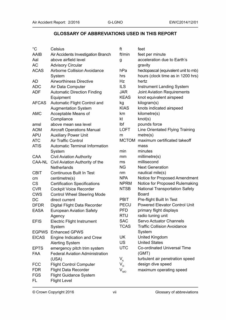
GLOSSARY OF ABBREVIATIONS USED IN THIS REPORT
°C CelsiusAAIB Air Accidents Investigation BranchAal above airfield levelAC Advisory CircularACAS Airborne Collision Avoidance
SystemAD Airworthiness DirectiveADC Air Data ComputerADF Automatic Direction Finding
EquipmentAFCAS Automatic Flight Control and
Augmentation SystemAMC Acceptable Means of
Complianceamsl above mean sea levelAOM Aircraft Operations ManualAPU Auxiliary Power UnitATC Air Traffic ControlATIS Automatic Terminal Information
SystemCAA Civil Aviation AuthorityCAA-NL Civil Aviation Authority of the
NetherlandsCBIT Continuous Built In Testcm centimetre(s)CS Certification SpecificationsCVR Cockpit Voice RecorderCWS Control Wheel Steering ModeDC direct currentDFDR Digital Flight Data RecorderEASA European Aviation Safety
AgencyEFIS Electric Flight Instrument
SystemEGPWS Enhanced GPWSEICAS Engine Indication and Crew
Alerting SystemEPTS emergency pitch trim systemFAA Federal Aviation Administration
(USA)FCC Flight Control ComputerFDR Flight Data RecorderFGS Flight Guidance SystemFL Flight Level
ft feetft/min feet per minuteg acceleration due to Earth’s
gravityhPa hectopascal (equivalent unit to mb)hrs hours (clock time as in 1200 hrs)Hz hertzILS Instrument Landing SystemJAR Joint Aviation RequirementsKEAS knot equivalent airspeedkg kilogram(s)KIAS knots indicated airspeedkm kilometre(s)kt knot(s)lbf pounds forceLOFT Line Orientated Flying Trainingm metre(s)MCTOM maximum certificated takeoff
massmin minutesmm millimetre(s)ms millisecondNG Next Generationnm nautical mile(s)NPA Notice for Proposed AmendmentNPRM Notice for Proposed RulemakingNTSB National Transportation Safety
BoardPBIT Pre-flight Built In TestPECU Powered Elevator Control UnitPFD primary flight displaysRTU radio tuning unitSAC Servo Actuator ChannelsTCAS Traffic Collision Avoidance
SystemUK United KingdomUS United StatesUTC Co-ordinated Universal Time
(GMT)VA turbulent air penetration speedVD design dive speedVMO maximum operating speed

Intentionally left blank
1
Air Accident Report: 2/2016 G-LGNO EW/C2014/12/01
© Crown Copyright 2016 Introduction and Summary
Air Accidents Investigation Branch
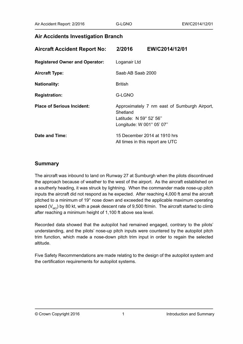
Aircraft Accident Report No: 2/2016 EW/C2014/12/01
Registered Owner and Operator: Loganair Ltd
Aircraft Type: Saab AB Saab 2000
Nationality: British
Registration: G-LGNO
Place of Serious Incident: Approximately 7 nm east of Sumburgh Airport, Shetland Latitude: N 59° 52’ 56’’ Longitude: W 001° 05’ 07’’
Date and Time: 15 December 2014 at 1910 hrs All times in this report are UTC
Summary
The aircraft was inbound to land on Runway 27 at Sumburgh when the pilots discontinued the approach because of weather to the west of the airport. As the aircraft established on a southerly heading, it was struck by lightning. When the commander made nose-up pitch inputs the aircraft did not respond as he expected. After reaching 4,000 ft amsl the aircraft pitched to a minimum of 19° nose down and exceeded the applicable maximum operating speed (VMO) by 80 kt, with a peak descent rate of 9,500 ft/min. The aircraft started to climb after reaching a minimum height of 1,100 ft above sea level.
Recorded data showed that the autopilot had remained engaged, contrary to the pilots’ understanding, and the pilots’ nose-up pitch inputs were countered by the autopilot pitch trim function, which made a nose-down pitch trim input in order to regain the selected altitude.
Five Safety Recommendations are made relating to the design of the autopilot system and the certification requirements for autopilot systems.

Intentionally left blank
3
Air Accident Report: 2/2016 G-LGNO EW/C2014/12/01
© Crown Copyright 2016 Section 1 - Factual information
1 Factual Information
1.1 History of the flight
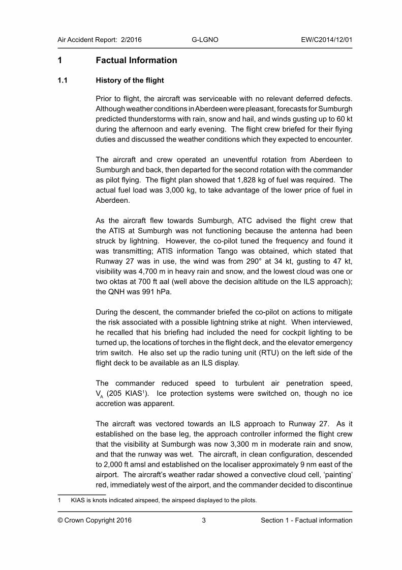
Prior to flight, the aircraft was serviceable with no relevant deferred defects. Although weather conditions in Aberdeen were pleasant, forecasts for Sumburgh predicted thunderstorms with rain, snow and hail, and winds gusting up to 60 kt during the afternoon and early evening. The flight crew briefed for their flying duties and discussed the weather conditions which they expected to encounter.
The aircraft and crew operated an uneventful rotation from Aberdeen to Sumburgh and back, then departed for the second rotation with the commander as pilot flying. The flight plan showed that 1,828 kg of fuel was required. The actual fuel load was 3,000 kg, to take advantage of the lower price of fuel in Aberdeen.
As the aircraft flew towards Sumburgh, ATC advised the flight crew that the ATIS at Sumburgh was not functioning because the antenna had been struck by lightning. However, the co-pilot tuned the frequency and found it was transmitting; ATIS information Tango was obtained, which stated that Runway 27 was in use, the wind was from 290° at 34 kt, gusting to 47 kt, visibility was 4,700 m in heavy rain and snow, and the lowest cloud was one or two oktas at 700 ft aal (well above the decision altitude on the ILS approach); the QNH was 991 hPa.
During the descent, the commander briefed the co-pilot on actions to mitigate the risk associated with a possible lightning strike at night. When interviewed, he recalled that his briefing had included the need for cockpit lighting to be turned up, the locations of torches in the flight deck, and the elevator emergency trim switch. He also set up the radio tuning unit (RTU) on the left side of the flight deck to be available as an ILS display.
The commander reduced speed to turbulent air penetration speed, VA (205 KIAS1). Ice protection systems were switched on, though no ice accretion was apparent.
The aircraft was vectored towards an ILS approach to Runway 27. As it established on the base leg, the approach controller informed the flight crew that the visibility at Sumburgh was now 3,300 m in moderate rain and snow, and that the runway was wet. The aircraft, in clean configuration, descended to 2,000 ft amsl and established on the localiser approximately 9 nm east of the airport. The aircraft’s weather radar showed a convective cloud cell, ‘painting’ red, immediately west of the airport, and the commander decided to discontinue
1 KIAS is knots indicated airspeed, the airspeed displayed to the pilots.
4
Air Accident Report: 2/2016 G-LGNO EW/C2014/12/01
© Crown Copyright 2016 Section 1 - Factual information
the approach. He informed the controller, and selected a southerly heading on the mode control panel. The autopilot remained engaged; the modes were heading select and altitude tracking2. The aircraft experienced turbulence but not to the degree that the crew had difficulty seeing flight deck instruments and displays.
As the aircraft rolled out on the heading, it was struck by lightning, which entered the airframe at the radome and exited at the APU exhaust (in the tail). ‘Ball lightning’ appeared briefly in the forward cabin immediately before the lightning strike. The commander was making a radio transmission to ATC about his intentions at the time, but when the lightning struck, he uttered an expletive and stopped transmitting.
The commander recalled3 that he informed the co-pilot that he (the commander) had control of the aircraft and began making nose-up pitch inputs, which he augmented with nose-up pitch trim inputs using the pitch trim switches on the control wheel. The co-pilot transmitted a MAYDAY to ATC, and the controller offered “all options” to the flight crew for an approach or diversion.
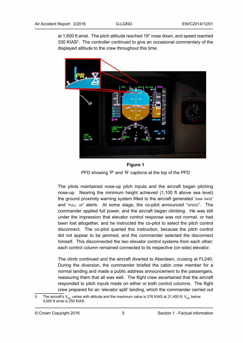
The aircraft climbed, but the commander perceived that his increasingly purposeful pitch control inputs did not appear to be having the expected effect. The co-pilot also applied nose-up pitch inputs and pitch trim inputs, but similarly perceived that the aircraft was not responding as expected. Pitch and roll mistrim indications were presented on the primary flight displays (PFDs) in the form of a flashing ‘P’ and an ‘R’ for the respective condition (Figure 1) and autopilot pitch and roll mistrim cautions were presented.
The commander instructed the co-pilot to select the elevator emergency trim switch on the flight deck overhead panel. This was done, and both pilots then made further inputs on the control-wheel-mounted pitch trim switches4. However, these had no effect, as the system had not detected the failure condition necessary to arm the emergency switch. The co-pilot asked the controller to read out the aircraft’s altitude as displayed on radar, which he did.
As the aircraft reached 4,000 ft amsl, the pitch attitude tended towards nose-down and a descent began. Invalid data from one of the air data computers then caused the autopilot to disengage. The pitch trim was, by this time, almost fully nose-down, and the aircraft continued to pitch nose-down and descend; full aft control column inputs were made. The peak rate of descent was 9,500 ft/min
2 In altitude tracking mode, the autopilot maintains the appropriate altitude or, if disturbed, endeavours to return the aircraft to it.
3 The duration of the CVR was 30 minutes and was overwritten by later recordings which began as the aircraft taxied to the stand at Aberdeen Airport.
4 The emergency elevator trim switch is armed when the system senses multiple failures. With the system operating, the control-wheel-mounted trim switches operate the emergency elevator actuators.
5
Air Accident Report: 2/2016 G-LGNO EW/C2014/12/01
© Crown Copyright 2016 Section 1 - Factual information
at 1,600 ft amsl. The pitch attitude reached 19° nose down, and speed reached 330 KIAS5. The controller continued to give an occasional commentary of the displayed altitude to the crew throughout this time.
Figure 1
PFD showing ‘P’ and ‘R’ captions at the top of the PFD
The pilots maintained nose-up pitch inputs and the aircraft began pitching nose-up. Nearing the minimum height achieved (1,100 ft above sea level) the ground proximity warning system fitted to the aircraft generated ‘sink rate’ and ‘pull up’ alerts. At some stage, the co-pilot announced “speed”. The commander applied full power, and the aircraft began climbing. He was still under the impression that elevator control response was not normal, or had been lost altogether, and he instructed the co-pilot to select the pitch control disconnect. The co-pilot queried this instruction, because the pitch control did not appear to be jammed, and the commander selected the disconnect himself. This disconnected the two elevator control systems from each other; each control column remained connected to its respective (on-side) elevator.
The climb continued and the aircraft diverted to Aberdeen, cruising at FL240. During the diversion, the commander briefed the cabin crew member for a normal landing and made a public address announcement to the passengers, reassuring them that all was well. The flight crew ascertained that the aircraft responded to pitch inputs made on either or both control columns. The flight crew prepared for an ‘elevator split’ landing, which the commander carried out
5 The aircraft’s VMO varies with altitude and the maximum value is 276 KIAS at 21,400 ft; VMO below 4,000 ft amsl is 250 KIAS.
6
Air Accident Report: 2/2016 G-LGNO EW/C2014/12/01
© Crown Copyright 2016 Section 1 - Factual information
without incident. The APU was not started after landing, because the flight crew were aware that the lightning strike might have caused damage in the tail area.
1.1.1 Flight crew recollection of the event
When interviewed, both pilots recalled that immediately the lightning struck, the autopilot disconnected and the ‘cavalry charge’ tone sounded. They had no recall of the climb above 2,000 ft amsl, but remembered that the aircraft began descending immediately after the lightning struck. Both remembered making nose-up pitch inputs in an effort to regain height, and the commander remembered endeavouring to follow the flight director, which he recalled was commanding nose-up pitch.
The commander did not recall having seen or heard any EICAS cautions or warnings during the event. He recalled that he had not considered selecting the flight controls page on the EICAS and suggested that this was a consequence of his long experience on a previous aircraft type (the Saab 340) which does not have such a display.
The commander recalled that, during the event, he found it necessary to make rudder inputs; he described having seen the slip indicator moving from its neutral position, and that the aircraft had been “lurching oddly”.
The co-pilot recalled seeing ‘PB’ or ‘PR’ annunciations on the PFD, and knew that the ‘P’ annunciation referred to an autopilot pitch mistrim, and ‘R’ likewise in roll. She was not aware of a ‘B’ annunciation having been mentioned in training or in the aircraft manual6, but did consider the possibility that this annunciation meant that a PBIT7 was in progress. She did not recall any mistrim cautions or warnings presented on the EICAS.
1.2 Injuries to persons
Injuries Crew Passengers Others
Fatal 0 0 0
Serious 0 0 0
Minor/None 3 30 0
6 There is no ‘B’ annunciation in this location on the PFD.7 Pre-flight Built In Test of the flight control system (see section 1.6.3).
7
Air Accident Report: 2/2016 G-LGNO EW/C2014/12/01
© Crown Copyright 2016 Section 1 - Factual information
1.3 Damage to the aircraft
Minor damage to the radome and APU exhaust.
1.4 Other damage
There was no other damage.
1.5 Personnel Information
1.5.1 Commander
Age: 42 years Licence: Airline Transport Pilot’s LicenceAircraft Rating: Saab 2000Licence Proficiency Check: Valid to 31 August 2015Instrument Rating: Valid to 31 August 2015Operator’s Line Check: Valid to 8 August 2015Medical Certificate: Valid to 3 June 2015Flying Experience: Total all types 5,780 hours On Type: 143 hours Last 90 days: 108 hours Last 28 days: 5 hours Last 24 hours: 5 hoursPrevious rest period: 17 hours
1.5.2 Co-pilot
Age: 35 yearsLicence: Commercial Pilot’s LicenceAircraft Rating: Saab 2000Licence Proficiency Check: Valid to 31 May 2015Instrument Rating: Valid to 31 May 2015Operator’s Line Check: Valid to 31 January 2015Medical Certificate: Valid to 13 April 2015Flying Experience: Total all types 1,054 hours On Type: 260 hours Last 90 days: 181 hours Last 28 days: 85 hours Last 24 hours: 3 hoursPrevious rest period: 17 hours
8
Air Accident Report: 2/2016 G-LGNO EW/C2014/12/01
© Crown Copyright 2016 Section 1 - Factual information
1.5.3 Flight crew information
The commander had flown privately and then worked as a flying instructor on single-engine piston aircraft until he joined the operator in 2005. He flew the Saab 340 aircraft, first as a co-pilot and then as commander. He converted to the Saab 2000, obtaining the type rating, in August 2014. At the time of the incident he had accrued a total of 5,780 hours, of which 4,640 were on the Saab 340, and 143 on the Saab 2000.
The co-pilot had flown single-engine piston aircraft privately from 2001 to 2012 before obtaining employment flying twin piston and Fairchild Metroliner aircraft from 2012 to 2014. She joined the operator in early 2014 and obtained the Saab 2000 type rating in May 2014. At the time of the incident she had accrued a total of 1,054 hours, of which 260 were on the Saab 2000.
During both pilots’ simulator training on the Saab 2000, elevator malfunctions were demonstrated, and a landing was carried out using only the elevator emergency pitch trim system for control in pitch.
The commander’s understanding of the functioning of the autopilot was explored during interview. Although he was aware that, in automatic flight, the control wheel moved in roll in response to autopilot action, he was not certain that the column moved similarly in pitch. Asked how the autopilot might be disengaged, he stated that operation of the pitch trim switches on the control wheels would cause it to disconnect, as would operation of the disconnect buttons on the control wheels, and a stall sensed by the aircraft’s systems. He was not aware of the meaning of the ‘P’ symbol presented on the PFD during the incident.
His expectation was that momentary loss of engine-driven generators was a likely consequence of a lightning strike in flight, and that this would result in loss of autopilot and EFIS8 screens. This understanding led to him ensuring his torch was to hand, and setting up the RTU as a back-up navigation display. He had not experienced a lightning strike before, nor did he recall any conversation with a Saab 2000 pilot who had experienced one. However, he had built up an understanding of the likely effects of a lightning strike on a Saab 340 during his time operating the type, and his expectation was built on that understanding.
The operator had included a Line Orientated Flying Training (LOFT) exercise within its Saab 340 training programme, in which a lightning strike was assumed to be the trigger for a double generator failure, as a consequence of which the autopilot disconnected. The commander of G-LGNO had received this training.
8 EFIS refers to the electronic flight instrument system which includes the PFDs, navigation displays and EICAS.
9
Air Accident Report: 2/2016 G-LGNO EW/C2014/12/01
© Crown Copyright 2016 Section 1 - Factual information
The operator had set out requirements on crew experience, which defined flight crew members as ‘inexperienced’ until they had accrued 100 flying hours and 10 sectors on the aircraft type within 120 days or 150 hours and 20 sectors (with no time limit) after completion of line flying under supervision, and prohibited ‘inexperienced’ pilots from flying together. Neither pilot was ‘inexperienced’ according to these criteria.
1.6 Aircraft Information
1.6.1 General information
Manufacturer: Saab ABType: Saab 2000Aircraft serial No: 2000-013Year of manufacture: 1995Number and type of engines: 2 x Allison AE 2100A turboprop enginesTotal airframe hours: 26,672 hoursTotal airframe cycles: 25,357 cyclesAirworthiness Review Certificate: Valid to 10 September 2015
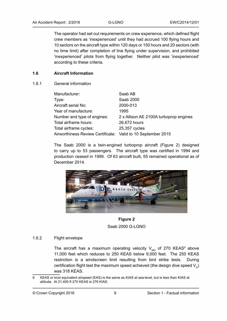
The Saab 2000 is a twin-engined turboprop aircraft (Figure 2) designed to carry up to 53 passengers. The aircraft type was certified in 1994 and production ceased in 1999. Of 63 aircraft built, 55 remained operational as of December 2014.
Figure 2
Saab 2000 G-LGNO
1.6.2 Flight envelope
The aircraft has a maximum operating velocity VMO of 270 KEAS9 above 11,000 feet which reduces to 250 KEAS below 9,000 feet. The 250 KEAS restriction is a windscreen limit resulting from bird strike tests. During certification flight test the maximum speed achieved (the design dive speed VD) was 318 KEAS.
9 KEAS or knot equivalent airspeed (EAS) is the same as KIAS at sea-level, but is less than KIAS at altitude. At 21,400 ft 270 KEAS is 276 KIAS.
10
Air Accident Report: 2/2016 G-LGNO EW/C2014/12/01
© Crown Copyright 2016 Section 1 - Factual information
1.6.3 Flight control system
The aircraft has a fly-by-wire elevator and rudder control system and a conventional mechanical aileron system for roll control. It has a fixed horizontal stabiliser and no elevator trim tabs. Pitch trim consists of elevator movement without associated control column movement.
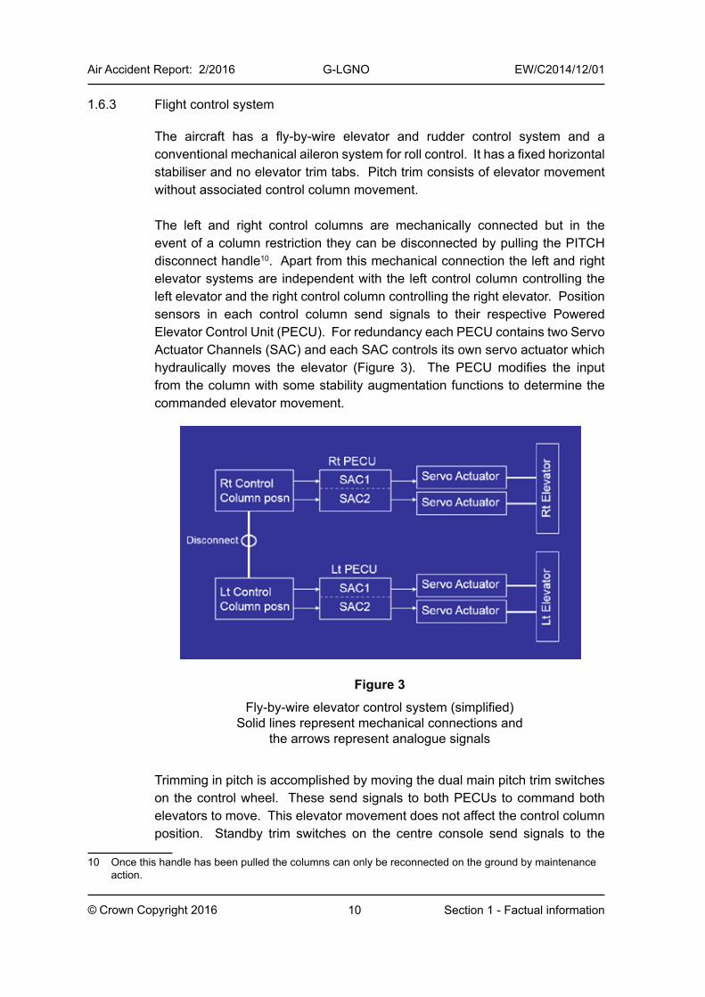
The left and right control columns are mechanically connected but in the event of a column restriction they can be disconnected by pulling the PITCH disconnect handle10. Apart from this mechanical connection the left and right elevator systems are independent with the left control column controlling the left elevator and the right control column controlling the right elevator. Position sensors in each control column send signals to their respective Powered Elevator Control Unit (PECU). For redundancy each PECU contains two Servo Actuator Channels (SAC) and each SAC controls its own servo actuator which hydraulically moves the elevator (Figure 3). The PECU modifies the input from the column with some stability augmentation functions to determine the commanded elevator movement.
Figure 3
Fly-by-wire elevator control system (simplified)Solid lines represent mechanical connections and
the arrows represent analogue signals
Trimming in pitch is accomplished by moving the dual main pitch trim switches on the control wheel. These send signals to both PECUs to command both elevators to move. This elevator movement does not affect the control column position. Standby trim switches on the centre console send signals to the
10 Once this handle has been pulled the columns can only be reconnected on the ground by maintenance action.
11
Air Accident Report: 2/2016 G-LGNO EW/C2014/12/01
© Crown Copyright 2016 Section 1 - Factual information
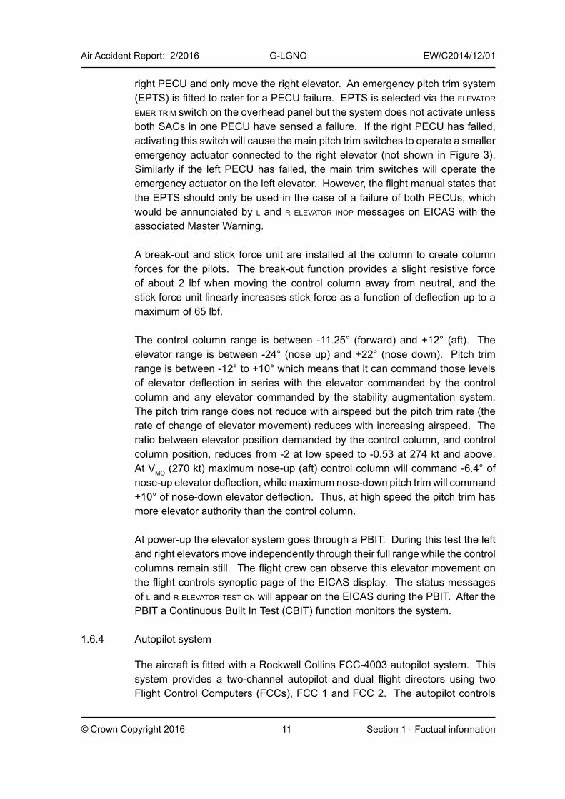
right PECU and only move the right elevator. An emergency pitch trim system (EPTS) is fitted to cater for a PECU failure. EPTS is selected via the elevator emer trim switch on the overhead panel but the system does not activate unless both SACs in one PECU have sensed a failure. If the right PECU has failed, activating this switch will cause the main pitch trim switches to operate a smaller emergency actuator connected to the right elevator (not shown in Figure 3). Similarly if the left PECU has failed, the main trim switches will operate the emergency actuator on the left elevator. However, the flight manual states that the EPTS should only be used in the case of a failure of both PECUs, which would be annunciated by l and r elevator inop messages on EICAS with the associated Master Warning.
A break-out and stick force unit are installed at the column to create column forces for the pilots. The break-out function provides a slight resistive force of about 2 lbf when moving the control column away from neutral, and the stick force unit linearly increases stick force as a function of deflection up to a maximum of 65 lbf.
The control column range is between -11.25° (forward) and +12° (aft). The elevator range is between -24° (nose up) and +22° (nose down). Pitch trim range is between -12° to +10° which means that it can command those levels of elevator deflection in series with the elevator commanded by the control column and any elevator commanded by the stability augmentation system. The pitch trim range does not reduce with airspeed but the pitch trim rate (the rate of change of elevator movement) reduces with increasing airspeed. The ratio between elevator position demanded by the control column, and control column position, reduces from -2 at low speed to -0.53 at 274 kt and above. At VMO (270 kt) maximum nose-up (aft) control column will command -6.4° of nose-up elevator deflection, while maximum nose-down pitch trim will command +10° of nose-down elevator deflection. Thus, at high speed the pitch trim has more elevator authority than the control column.
At power-up the elevator system goes through a PBIT. During this test the left and right elevators move independently through their full range while the control columns remain still. The flight crew can observe this elevator movement on the flight controls synoptic page of the EICAS display. The status messages of l and r elevator test on will appear on the EICAS during the PBIT. After the PBIT a Continuous Built In Test (CBIT) function monitors the system.
1.6.4 Autopilot system
The aircraft is fitted with a Rockwell Collins FCC-4003 autopilot system. This system provides a two-channel autopilot and dual flight directors using two Flight Control Computers (FCCs), FCC 1 and FCC 2. The autopilot controls
12
Air Accident Report: 2/2016 G-LGNO EW/C2014/12/01
© Crown Copyright 2016 Section 1 - Factual information
the aircraft in pitch by mechanically moving both control columns via an electric pitch servo mechanically connected to the right column. It also sends pitch trim signals to both PECUs to move the elevators to offload the servo and allow the control column to centralise in trimmed flight. The autopilot controls roll by mechanically moving the control wheels via an electric roll servo, but does not control roll trim. The system also provides yaw damping and yaw trim commands to the rudder control system.
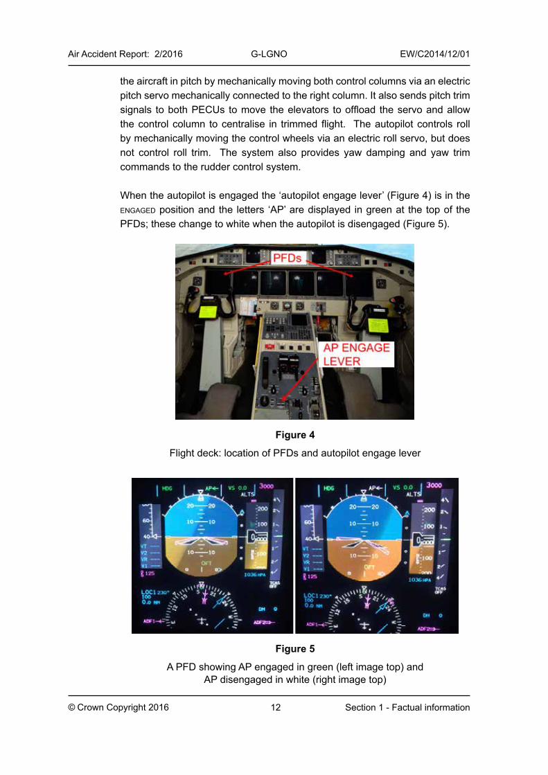
When the autopilot is engaged the ‘autopilot engage lever’ (Figure 4) is in the engaged position and the letters ‘AP’ are displayed in green at the top of the PFDs; these change to white when the autopilot is disengaged (Figure 5).
Figure 4
Flight deck: location of PFDs and autopilot engage lever
Figure 5
A PFD showing AP engaged in green (left image top) and AP disengaged in white (right image top)
13
Air Accident Report: 2/2016 G-LGNO EW/C2014/12/01
© Crown Copyright 2016 Section 1 - Factual information
The autopilot can be manually disengaged in the following ways:
● pressing the disengage button on either control wheel
● moving the autopilot engage lever on the centre pedestal to disengaged
● moving the standby trim switches on the centre pedestal
● pushing the power lever go-around palm switches
The autopilot will automatically disengage if it receives invalid system input data. It will also disengage if bank angle exceeds 45°, or pitch attitude exceeds -17° (nose down) or 25° (nose up). Autopilot disengagement is accompanied by an audible ‘cavalry charge’ alert, which continues until an autopilot disengage button is depressed.
The main pitch trim switches on the control wheel are inhibited when the autopilot is engaged and moving these switches will not cause the autopilot to disengage or trim to occur. If the pilot tries to move the control column while the autopilot is engaged the pilot can overpower the autopilot pitch servo, but the autopilot remains engaged and may, depending on selected settings, command opposing pitch trim. For example, if altitude tracking mode is engaged and the pilot pulls the column aft, the pilot will feel a higher force than if the mode were not engaged, and the autopilot will trim nose down to regain the selected altitude. This will also result in a flashing ‘P’ being displayed on the PFD. If the pilot’s inputs are maintained continuously for at least 10 seconds an ap pitch mistrim caution message will appear on the EICAS with an associated flashing amber Master Caution light and a single aural chime; the ‘P’ will stop flashing, but the autopilot will remain engaged. Similarly, if the pilot overpowers the autopilot roll servo by moving the control wheel a flashing ‘R’ will be displayed on the PFD. If this input is maintained for at least 10 seconds an ap roll mistrim caution message will be triggered and the ‘R’ will stop flashing.
The Aircraft Operations Manual (AOM) for the Saab 200011 stated the following regarding autopilot mistrim:
‘The aircraft must be trimmed out before autopilot engagement. With the autopilot engaged, any pitch and roll mistrim is announced by an amber P and R on the PFD respectively. If a mistrim condition exists longer than 10 seconds, an AP PITCH MISTRIM and/or AP ROLL MISTRIM caution is announced.’
11 Saab 2000 Aircraft Operations Manual Revision 44, Oct 01/14.
14
Air Accident Report: 2/2016 G-LGNO EW/C2014/12/01
© Crown Copyright 2016 Section 1 - Factual information
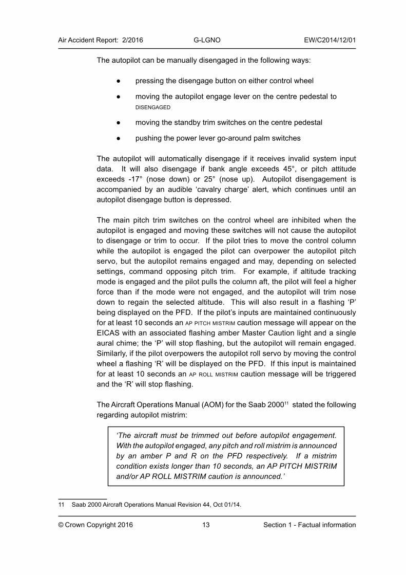
The AOM did not state that a ‘P’ or ‘R’ on the PFD could be an indication that the pilot was overriding the autopilot. There was no checklist in the AOM for the flight crew to follow for a flashing ‘P’ or ‘R’ on the PFD; however, there was a checklist to follow for the ap pitch mistrim and ap roll mistrim cautions as shown in Figure 6.
The additional control forces required to overpower the autopilot pitch servo and the roll servo are approximately 25 lbf and 50 lbf respectively as measured at the control wheel.
Figure 6
Saab 2000 Malfunction Checklists for ap pitch mistrim and ap roll mistrim
1.6.5 Air Data Computer system
The aircraft is fitted with two Rockwell Collins ADC-850 Air Data Computers (ADCs). These ADCs independently determine airspeed, pressure altitude and other parameters. ADC 1 provides data to the captain’s flight displays and FCC 1, while ADC 2 provides data to the co-pilot’s flight displays and FCC 2. If an FCC detects invalid data from its ADC it will cause the autopilot to disengage.
1.6.6 Maintenance history
The aircraft had accumulated 26,672 hours and 25,357 cycles at the time of the incident. There was no recent maintenance or any deferred defects in the technical log of relevance to this incident. Three sectors prior to the incident, after engine start, the crew received left elevator maintenance and
15
Air Accident Report: 2/2016 G-LGNO EW/C2014/12/01
© Crown Copyright 2016 Section 1 - Factual information
right elevator maintenance status messages on the EICAS but these cleared after the PBIT. A download of the maintenance messages revealed that on 10 December 2014 an adc invalid data message was recorded but this occurred on the ground prior to departure and did not require maintenance action. The adc invalid data message can be triggered on the ground due to an electrical power cycle between the APU and engine generators.
1.6.7 Autopilot system requirements for initial Saab 2000 certification
The Saab 2000 was certificated in 1994 to Joint Aviation Requirement12 JAR-25 Change 13 (1989) and FAA Federal Aviation Regulation FAR-25 as amended by 25-1 through 25-71 (1990). The requirements for the ‘Automatic Pilot System’ were in JAR 25.1329 and FAR 25.1329. Both requirements stated that the autopilot must be designed so that it can be quickly and positively disengaged by the pilots using quick release controls on both control wheels, and means must be provided to indicate to the flight crew the current mode of operation and any modes armed by the pilot. Selector switch position was not acceptable as a means of indication.
There were no requirements related to how the autopilot should respond if the flight crew applied an override force to the flight controls. However, in the Acceptable Means of Compliance document for JAR-25.1329 (ACJ 25.1329) it stated that: ‘It should be possible to disengage the automatic pilot at any time without unacceptable out-of-trim forces’ and that for systems with Control Wheel Steering Mode (CWS)13: ‘It should be possible for the pilot to overpower the automatic pilot and to achieve the maximum available control surface deflection without using forces so high that the controllability requirements of JAR 25.143(c) are not met.’ The Saab 2000, however, was not fitted with CWS and therefore according to EASA and the aircraft manufacturer this latter provision was not applicable.
1.6.7.1 Current requirements
In May 2006 the FAA published a revised and more detailed set of requirements for the autopilot system on Part 25 aircraft14. This was in response to a series of incidents and accidents that highlighted difficulties for flight crews interacting with the increasing automation of flight decks. It was also in response to recommendations made in the FAA’s Human Factors Team report titled ‘The Interfaces between Flightcrews and Modern Flight Deck Systems’ (published 18 June 1996).
12 The Joint Aviation Requirements were the requirements of the Joint Aviation Authorities which have been superseded by the European Aviation Safety Agency (EASA) Certification Specifications (CS).
13 Control Wheel Steering Mode is an autopilot mode that takes inputs from pilot movement of the control wheel
14 ‘Part 25 aircraft’ in this report refers to aircraft certified to FAR-25, JAR-25 or CS-25 which are primarily large turbine powered aeroplanes with a maximum takeoff mass of greater than 5,670 kg.
16
Air Accident Report: 2/2016 G-LGNO EW/C2014/12/01
© Crown Copyright 2016 Section 1 - Factual information
Amendment 25-119 to FAR 25.1329, effective from 11 May 2006, renamed section 1329 to ‘Flight guidance system’ (FGS) and introduced a number of new requirements including 25.1329(l) which stated that:
‘The autopilot may not create a potential hazard when the flightcrew applies an override force to the flight controls.’ (FAR 25.1329(l))
EASA introduced a similar series of amendments to CS 25.1329 in December 2007 with Amendment 4 which included a new requirement under 25.1329(l) which stated that:
‘The autopilot must not create an unsafe condition when the flight crew applies an override force to the flight controls.’ (CS 25.1329(l))
Both of these requirements were still current at the time of writing. The FAA uses the terms ‘may’ and ‘potential hazard’ whereas EASA uses the terms ‘must’ and ‘unsafe condition’. However, EASA considered that this difference in wording was not significant and the regulations would still be considered to be harmonised.
The rationale behind this new requirement and the reason for using the term ‘potential hazard’ in the FAA requirement is explained in the FAA’s Notice for Proposed Rulemaking (NPRM15) which states the following concerning 25.1329(l):
‘This new paragraph requires that flightcrew override of the autopilot must not create a potential hazard when the flightcrew applies an override force to the flight controls. As stated previously in the discussion on Sec. 25.1329(d), an override occurs when the pilot or first officer applies input to the flight deck controls without first manually disengaging the autopilot. Pilot override may not always result in autopilot disengagement. If the autopilot does not disengage during override, the result might be an out-of-trim condition (for example, a horizontal stabilizer/elevator jackknife, where the surfaces are aerodynamically opposing each other). This could result in a significant transient and/or loss of control if the autopilot were to be disconnected or if the pilot were to suddenly release the force being applied to the flight deck controls while the airplane is in this configuration. Several accidents and incidents have occurred after flightcrew override of the autopilot. Nevertheless, it is not advisable to prohibit flightcrew override in all cases, because override might be the last resort for the
15 FAA NPRM 14 CFR Part 25 RIN 2120-AI41 ‘Safety Standards for Flight Guidance Systems’, published 13 August 2004.
17
Air Accident Report: 2/2016 G-LGNO EW/C2014/12/01
© Crown Copyright 2016 Section 1 - Factual information
flightcrew to regain control of the airplane in certain abnormal (failure) conditions or in an emergency avoidance maneuver.
This rule paragraph is changed from the original ARAC recommendation. That proposed rule language used the term “unsafe condition.” The FAA revised this rule paragraph to use the term “potential hazard” instead of “unsafe condition.” The reason behind this revision is that the term “unsafe condition” has a very definite meaning within the context of FAA regulations. Under 14 CFR part 39, we issue airworthiness directives when we determine that an “unsafe condition” is likely to exist or develop on other products of the same type design. Proposed paragraph (l) addresses a specific type of hazard, and so the use of the broad term “unsafe condition,” with its many implications under part 39, is inappropriate. Also, Sec. 21.21(b)(2) prohibits certification of any aircraft which contains unsafe design features, so the original wording of this paragraph would be redundant of the part 21 rule. Therefore, the FAA revised this rule paragraph to refer to “potential hazard” instead.
This preamble does not attempt to give a complete definition of the term “potential hazard.” The FAA cannot define all airplane configurations that should be considered potentially hazardous that may occur during a flightcrew override. To do so would be too restrictive, as this would assume the FAA is able to fully define all hazardous or potentially hazardous conditions that might result for all current and future FGS and airplane designs. What this term means is anything that could significantly reduce safety margins or invalidate any assumption or premise made by the System Safety Assessment.
The term “potential hazard” used above is intended to describe possible future hazards if another event were to happen with the airplane in a specific configuration during the override. That event might be an autopilot disengagement, the pilot abruptly releasing the controls, or another failure that occurs during the flightcrew override. Therefore, the term “potential hazard” is not fully defined. Rather, a description of the concept has been used to explain what is meant and how compliance with this paragraph could be demonstrated. Proposed paragraph (l) should be evaluated under “normal conditions” discussed elsewhere in this document.’
18
Air Accident Report: 2/2016 G-LGNO EW/C2014/12/01
© Crown Copyright 2016 Section 1 - Factual information
Both the FAA and EASA publish acceptable means for showing compliance with their respective 25.1329 requirements. The FAA published Advisory Circular (AC) 25.1329-1B in July 2006 to explain how the requirements in FAR 25.1329 (Amdt 25-119) could be met. This has since been updated to AC 25.1329-1C (October 2014). EASA include Acceptable Means of Compliance (AMC) material within the CS-25 publication, and its revised AMC to 25.1329 was introduced with Amendment 4 of CS-25 in 2007. This section is now at Amendment 12 (13 July 2012). The wording in AC 25.1329-1C and AMC 25.1329 is similar but there are some differences. This report will quote sections from AC 25.1329-1C; the equivalent sections of AMC 25.1329 are included in Appendix A.
Section 30(b)(1) of AC 25.1329-1C concerns autopilot override with automatic disengagement. It states that:
‘The autopilot should disengage when the flightcrew applies a significant override force to the controls. The applicant should interpret “significant” as a force that is consistent with an intention to overpower the autopilot by either or both pilots.’
A subsequent note states that 25 lbf has been determined to be significant for other than approach operations.
The same section states that:
‘Sustained application of force below the disengagement threshold may not result in a potential hazard. See 25.1329(l). For example, the automatic trim should not run to oppose the override of the autopilot by the flightcrew that would result in unacceptable airplane motion, if the autopilot were to automatically disengage or be manually disengaged.’
However, section 30(b)(2) of AC 25.1329-1C permits autopilot override without automatic disengagement. It states that:
‘If the FGS is not designed to disengage in response to any override force, then the response to an override may not result in a potential hazard. Sustained application of an override force may not result in a potential hazard, such as when the flightcrew abruptly releases the force on the controls. See 25.1329(l). Mitigation may be accomplished through provision of an appropriate alert and flightcrew procedure.’
19
Air Accident Report: 2/2016 G-LGNO EW/C2014/12/01
© Crown Copyright 2016 Section 1 - Factual information
AC 25.1329-1C includes a section on ‘Alternative means of autopilot disengagement’. It states that ‘activating the trim switch on the wheel’ is an acceptable means of providing an alternative autopilot disengagement. In terms of ‘Flightcrew pitch trim input’ it states that:
‘If the autopilot is engaged and the pilot applies manual pitch trim input, and the autopilot is designed to disengage because of that flightcrew action, the autopilot must disengage with no more than a minor transient. See 25.1329(c). Alternatively, pitch trim changes may be inhibited, such that the potential for a transient is removed.’
The FAA has clarified to the AAIB that this means manual pitch trim input changes may be inhibited. It does not mean that trim changes commanded by the autopilot in opposition to the pilot’s manual pitch trim inputs should be inhibited.
1.6.7.2 EASA and FAA interpretation on whether the Saab 2000 would meet the current 25.1329(l) requirements
The FAA reported to the AAIB that it did not think the Saab 2000 would meet the current requirement in FAR 25.1329(l) as it considered that the Saab 2000’s autopilot system could create a potential hazard during a flight crew force override, particularly given that the automatic trim can apply full nose-up or nose-down trim to oppose the override to the extent that the pilot’s inputs become ineffective, resulting in an unacceptable aircraft response. The FAA did not think that the Saab 2000’s pitch mistrim alerting system would meet the ‘appropriate alert’ criteria of AC 25.1329, but that regardless of the alerting system it would be difficult to show compliance with 25.1329(l) because of the aircraft’s trim response.
The EASA reported to the AAIB that it could not determine the compliance of the Saab 2000 design to CS 25.1329(l) and the associated AMC, which involves a combination of autopilot disconnect logics and cockpit alerts. Furthermore, it stated that establishing compliance would require analysis of detailed design data, including safety assessment, and an in-flight and simulator evaluation.
1.6.7.3 Design rationale for the Saab 2000 autopilot system during flight crew override
The aircraft manufacturer did not provide any documentation to explain the design decisions that led to an autopilot system that would not disengage following flight crew force override or main pitch trim switch operation, while allowing the auto-trim system to oppose the crew’s inputs. The people involved in the system design had since retired from the company. The aircraft manufacturer stated that the design decision to inhibit the pitch trim
20
Air Accident Report: 2/2016 G-LGNO EW/C2014/12/01
© Crown Copyright 2016 Section 1 - Factual information
switches during autopilot engagement was taken by the autopilot avionics manufacturer. The autopilot avionics manufacturer stated that this design decision came from the aircraft manufacturer but could not produce any supporting documentation.
The aircraft manufacturer stated that modifying the aircraft to allow the pitch trim switches to disengage the autopilot would not improve the system design as the frequency of inadvertent disengagement would increase. It stated that the autopilot system’s main objective was:
‘not to disconnect, but to provide assistance to a crew who is rated for the aircraft and are able to provide system monitoring in a professional manner.’
The aircraft manufacturer also stated that for the G-LGNO incident:
‘it can be noted that an autopilot system with a different design, causing the autopilot to disconnect, combined with a crew with such a high level of disorientation and causing contradictory control inputs could have resulted in more serious outcome.’
1.6.8 Aircraft examination
A detailed post-lightning strike inspection of the aircraft was performed. There were a few small soot marks with some surface damage on the radome but no holes, and some heat damage to a stiffener inside the radome. There was also damage to a rivet and one screw aft of the radome. The APU exhaust was damaged with sections of molten metal around its trailing edges. An overspeed inspection was also performed which did not reveal any damage.
Functional tests and inspections of the elevator control system and autopilot system did not reveal any faults. The autopilot disengaged when the autopilot disconnect switches were pressed. Applying a force override to the controls caused a flashing ‘P’ and ‘R’ to be displayed, and when the force was held for at least 10 seconds the master caution and associated pitch and roll ‘mistrim’ indications were triggered (this test was performed on the ground with both engines running).
A download of the fault history revealed that FCC 2 had caused the autopilot to disengage at 1913 hrs due to invalid data from ADC 2. This could have been due to missing data or bad data from the ADC for a period of at least 99 ms. However, there was no adc invalid data message stored in the maintenance messages file indicating that there had probably been a very short period of invalid data. A pitot static test was performed to check the primary ADC
21
Air Accident Report: 2/2016 G-LGNO EW/C2014/12/01
© Crown Copyright 2016 Section 1 - Factual information
parameters and all measurements were within specification. The aircraft has since flown in service without any reported flight control or autopilot problems (as of 20 March 2015). On 20 January 2015 there was one maintenance message for adc invalid data but this occurred on the ground 52 minutes after arrival while the aircraft may have been undergoing maintenance16.
1.7 Meteorological information
1.7.1 Conditions in flight
The event occurred at an altitude of 2,000 ft; the outside air temperature was -0.5°C. Precipitation was ‘painting’ in red on the aircraft’s weather radar, but this could not be associated with a specific rate of rainfall.
1.7.2 Handbook of Aviation Meteorology
The Handbook of Aviation Meteorology17 states ‘A lightning strike can be very unpleasant for the occupants of an aircraft… The brilliant flash, the smell of burning and the explosive noise may be alarming and distracting…’. The Handbook notes that many aircraft have been struck by lightning without sustaining significant damage, but adds ‘…there is a danger that in the turbulence of a storm the disconcerting effects may lead to disorientation and loss of control unless pilots are fully prepared’.
1.7.3 Triggered lightning
Examination of meteorological information shows that the aircraft experienced a ‘triggered’ lightning strike, which was detected and recorded in the aircraft’s position at 1910:20 hrs by a lightning detection system used by the Met Office.
‘Triggered’ lightning is a phenomenon previously identified as being of particular relevance to helicopter operations in the North Sea. Joint work by the CAA and Met Office to address this hazard in that region has identified that it occurs:
● between October and early April,
● when the temperature between 2,000 and 3,000 ft is between -2 and -6°C,
● precipitation is above 4mm/hr,
● the height of the freezing level is between 1,000 and 3,000 ft.
16 Placing the aircraft on jacks can trigger this message.17 Meterological Office ISBN 0 11 400365 3, third edition.
22
Air Accident Report: 2/2016 G-LGNO EW/C2014/12/01
© Crown Copyright 2016 Section 1 - Factual information
Electrical charge builds up in convective clouds but is insufficient to release lightning without external influence. Aircraft gather charge as they fly, and an aircraft close to the cloud may trigger a strike. Normal techniques for avoiding significant convective weather, such as use of airborne weather radar, do not guard against triggered lightning strikes. Forecasts are provided to North Sea helicopter operators, but not fixed-wing operators.
1.7.4 Saab 2000 and Saab 340 response to lightning strikes
The aircraft manufacturer reviewed reports received from operators of lightning strikes on Saab 340 and Saab 2000 aircraft. There were three lightning strike reports for the Saab 2000 and none of these reported a disengagement of the autopilot. There were 13 lightning strike reports for the Saab 340 of which:
● One reported that the autopilot disengaged due to a loss of DC generation.
● Five reported a loss of DC generation which may have led to autopilot disengagement if it had been engaged at the time.
● The remaining seven did not report a loss of DC generation or autopilot disengagement.
These reports do not represent a complete list of all Saab 340 and Saab 2000 lightning strikes as these events are not required to be reported to the manufacturer.
1.7.5 Instructions and information provided to flight crew concerning lightning strikes
The operator’s operations manual Parts A and B gave instructions and information relating to flight near thunderstorms. For details see Appendix B.
1.8 Aids to navigation
Not relevant.
1.9 Communications
Not relevant.
1.10 Aerodrome information
Not relevant.
23
Air Accident Report: 2/2016 G-LGNO EW/C2014/12/01
© Crown Copyright 2016 Section 1 - Factual information
1.11 Flight recorders
The aircraft was fitted with a solid state flight data recorder (FDR) and cockpit voice recorder (CVR). These were downloaded at the AAIB where the recordings were analysed.
1.11.1 Cockpit voice recorder
The duration of the CVR was 30 minutes and was overwritten by later recordings which began as the aircraft taxied to the stand at Aberdeen Airport.
The absence of relevant cockpit voice recordings in previous occurrences has prompted recommendations for the duration of CVRs to be increased. This has resulted in the requirement that CVRs with a minimum duration of 2 hours be fitted to commercial air transport aircraft with a MCTOM18 greater than 5,700 kg, issued with an individual certificate of airworthiness on or after 1 April 1998 (G-LGNO was manufactured in 1995). Further changes are proposed in EASA NPA19 2013-26 and EASA Opinion 01/2014 (Amendment of requirements for flight recorders and underwater locating devices) that, in part, will phase out all 30-minute CVRs by 1 January 2019, and replace them with CVRs with a minimum duration of 2 hours. This Opinion also introduces the requirement for larger aircraft (MCTOM greater than 27,000 kg) to be fitted with even longer duration CVRs. This and other opinions are being reviewed as part of the legislative process to update the current regulations.
1.11.2 Flight data recorder
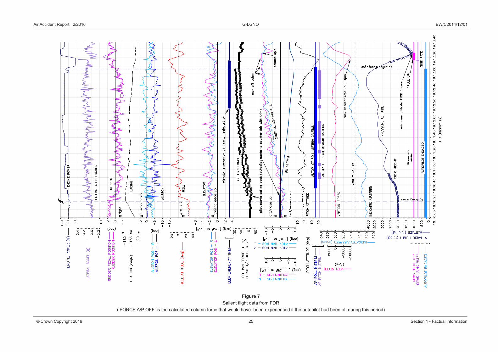
Relevant data from the FDR is presented at Figure 7. The figure starts at 1910 hrs, 20 seconds before the lightning strike, with the aircraft in a left turn, at 2,000 ft amsl (991 hPa), 220 KIAS, with the autopilot engaged in heading select and altitude tracking modes. At this altitude the outside air temperature was -0.5°C.
Immediately after the lightning strike, the aircraft rolled wings level. Aft control column pilot inputs were then made together with small increases in engine power which caused the aircraft to climb20. The pitch trim (commanded by the autopilot) then began to move in the opposite direction trying to regain the selected altitude of 2,000 ft. With the autopilot engaged, the pilots needed to apply an additional 24 lbf on top of the forces generated by the break-out and stick force unit, in order to move the elevator.
18 MCTOM is the maximum certificated takeoff mass.19 NPA is a Notice for Proposed Amendment.20 As the autopilot was engaged in altitude tracking at 2,000 ft any aft column inputs while the aircraft was
at or above 2,000 feet must have been commanded by the pilot(s).
24
Air Accident Report: 2/2016 G-LGNO EW/C2014/12/01
© Crown Copyright 2016 Section 1 - Factual information
Over the next two and a half minutes, increasing (aft) force21 was applied to the column that continually overpowered the autopilot, while the autopilot continued to command opposite pitch trim. With these control column inputs and several engine power changes, the aircraft continued to climb, in a number of steps, towards 4,000 ft amsl. The airspeed also increased, gaining an additional 20 kt to 240 KIAS by the time 4,000 ft was reached but peaking at 265 KIAS, 15 kt in excess of the VMO.
During this period, a small right rudder input was applied with varying amounts of aileron input, causing the aircraft to bank between zero and about 20° left; however, the overall effect was some lateral acceleration to the right and for the aircraft to turn gently to the right through about 45° onto a south-westerly heading.
Also during this period, as the aircraft climbed through 2,100 ft, an autopilot roll mistrim caution was recorded, followed between 8 and 16 seconds later by an autopilot pitch mistrim caution (with the corresponding flashing ‘R’ and ‘P’ indications on the PFD becoming steady)22. The roll mistrim caution remained active for the next two and a half minutes whereas the pitch mistrim caution was intermittent during the same period but active for the majority of it. The elevator emergency trim switch was selected on as the aircraft passed through 3,325 ft amsl; however, this had no effect (as the system had not detected a failure condition necessary to arm the switch).
As the aircraft reached 4,000 ft amsl, the pilots were pulling in excess of 80 lbf on the control column, with the column almost fully aft. The autopilot continued to command nose-down pitch trim and for about 10 seconds the aircraft remained at just over 4,000 ft during which the pitch attitude started to decrease and the aircraft accelerated. The pitch trim then stopped at just under 9° nose-down (out of a maximum of 10°) and within 5 seconds the aircraft was descending at 1,500 ft/min and accelerating, at which point the engine power was reduced to 50%.
The aircraft continued to descend and accelerate and the power was further reduced to about 5% (flight idle); however, within 6 seconds, as the aircraft descended though 3,600 ft at a rate of 4,250 ft/min (and increasing), the autopilot disengaged (time 19:13:06 on Figure 7). The pitch attitude at this point was 10° nose down.
21 Column force was calculated from the column position parameter recorded by the FDR and the force versus position data provided by the manufacturer.
22 The uncertainty in the timing of the mistrim cautions is a consequence of the FDR discretes for the autopilot mistrim cautions (and ‘P’ and ‘R’ out of trim conditions) being recorded once every four seconds.
Air Accident Report: 2/2016 G-LGNO EW/C2014/12/01
Figure 7Salient flight data from FDR
(‘FORCE A/P OFF’ is the calculated column force that would have been experienced if the autopilot had been off during this period)
25© Crown Copyright 2016 Section 1 - Factual information

27
Air Accident Report: 2/2016 G-LGNO EW/C2014/12/01
© Crown Copyright 2016 Section 1 - Factual information
During the next 5 seconds, with the column fully aft, the pitch trim still at about 90% of maximum nose down, and engine power still at about 5%, the aircraft passed through 2,800 ft at a rate of descent of 6,800 ft/min (and increasing). The airspeed was now 292 KIAS.
The pilots maintained full aft control column and applied nose-up pitch trim inputs23, and the aircraft began pitching up just as the EGPWS issued a ‘sink rate’ alert. This was followed by ‘pull up’ alerts for the next 9 seconds during which the peak rate of descent recorded was 9,500 ft/min as the aircraft descended through 1,600 ft amsl. Full power was also applied.
Shortly afterwards, and just before the aircraft started to climb, the pitch control disconnect was selected24 (necessitating independent control column pitch control inputs for the remainder of the flight back to Aberdeen). As the aircraft started to climb away the EGPWS ‘pull up’ alerts stopped.
The minimum pitch attitude recorded during the descent was 19° nose down and the maximum airspeed was 330 KIAS. The peak normal acceleration during the recovery was 2.3 g. The minimum recorded height was between 1,050 and 1,100 ft amsl from the left and right ADCs respectively. (The minimum recorded radio height was 1,190 ft a couple of seconds earlier.)
1.12 Wreckage and impact information
Not relevant.
1.13 Medical and pathological information
Not relevant.
1.14 Fire
There was no fire.
1.15 Survival aspects
Not relevant.
23 These pitch trim inputs were now effective because the autopilot had disengaged.24 The disconnection between the columns is evident in the large split between the left and right column
position parameters.
28
Air Accident Report: 2/2016 G-LGNO EW/C2014/12/01
© Crown Copyright 2016 Section 1 - Factual information
1.16 Test and research
1.16.1 Flight mechanics modelling
The aircraft manufacturer carried out calculations using its computer based flight mechanical simulation model (known as ARES) of the Saab 2000 to establish if the recorded flight dynamics of the aircraft after the lightning strike were consistent with the recorded control surface deflections. This used a six degree-of-freedom simulation model of the aircraft, which modelled lift and drag coefficient data throughout the angle of attack range (up to stall). Limitations in the model meant that the effects of turbulence and gusts could not be simulated.
The model, which did not include an autopilot, was driven by recorded elevator position, power lever angle and rudder position. A mathematical pilot controller was used to control the aileron to maintain wings-level flight because too many errors were introduced when recorded aileron position was used. The low sample rate of these recorded parameters (typically once per second) meant that they had to be smoothed and resampled at 10 Hz for them to be useable as input drivers to the simulation model. The low sample rate also meant that the actual movement of the controls, if cyclical in nature at a high enough frequency, could have been missed or aliased25 when sampled and recorded.
Selected portions of the incident flight were simulated and the results compared with the actual recorded flight data. The simulation model was trimmed at the start of each of these in order to remove from the result any differences in the ARES Saab 2000 model compared to G-LGNO. To build confidence in the method, initially comparisons were made in portions of the flight, such as the cruise, where changes were relatively small and un-dynamic compared to the portion of interest. The climb following the lightning strike, and top of climb and descent to 1,100 ft amsl were then modelled and comparisons made with the recorded flight data.
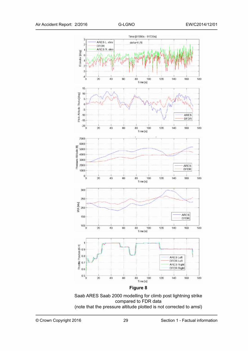
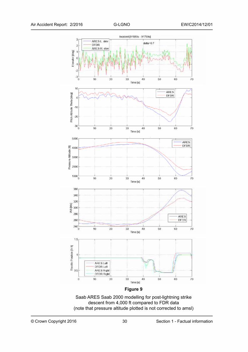
The resulting comparisons are presented in Figure 8 and Figure 9 for the climb and descent respectively. They show a good correlation between the simulation (labelled ARES) and the recorded data (labelled DFDR). In particular, there was close matching in frequency of the small variations in pitch attitude in direct response to the elevator inputs. However, the inaccuracies in the aerodynamic model, errors in the re-sampling of input data (which itself could have been aliased), and external factors not modelled, meant the magnitude of the responses was not always accurate, with errors accumulating over time. For the slower trends in the recorded data, the simulation followed these reasonably well and did so for several minutes at a time, such as during the climb portion of
25 Aliasing is the process where a sinusoid changes from one frequency to another as a result of sampling.
Air Accident Report: 2/2016 G-LGNO EW/C2014/12/01
29© Crown Copyright 2016 Section 1 - Factual information
Figure 8
Saab ARES Saab 2000 modelling for climb post lightning strike compared to FDR data
(note that the pressure altitude plotted is not corrected to amsl)
30
Air Accident Report: 2/2016 G-LGNO EW/C2014/12/01
© Crown Copyright 2016 Section 1 - Factual information
Figure 9
Saab ARES Saab 2000 modelling for post-lightning strike descent from 4,000 ft compared to FDR data
(note that pressure altitude plotted is not corrected to amsl)
31
Air Accident Report: 2/2016 G-LGNO EW/C2014/12/01
© Crown Copyright 2016 Section 1 - Factual information
the flight after the lightning strike. For the shorter modelling period of the top of climb and descent portion of the flight the simulation better matched the flight data and smaller differences were achieved.
In summary, however, the Saab modelling work confirmed that the pitch, altitude and airspeed excursions of G-LGNO following the lightning strike were consistent with the flight control deflections. A separate calculation was made which confirmed that the elevator deflections were consistent with the control column deflections and pitch trim inputs.
The simulation model was then used to assess the effect of power during the pull-up from the descent to 1,100 ft amsl. This demonstrated that by leaving the power levers at the flight idle position the aircraft still would have recovered from the dive with a similar minimum altitude.
1.16.2 Crew override effects on autopilot systems on other commercial aircraft types
The autopilot system on the Saab 2000 has the following attributes when flight crew override inputs are made with the autopilot engaged:
1. Applying an override force to the column will move the elevator but will not cause the autopilot to disengage
2. The autopilot can trim in the opposite direction to the pilot applied column input
3. Pressing the main pitch trim switches has no effect and will not cause the autopilot to disengage
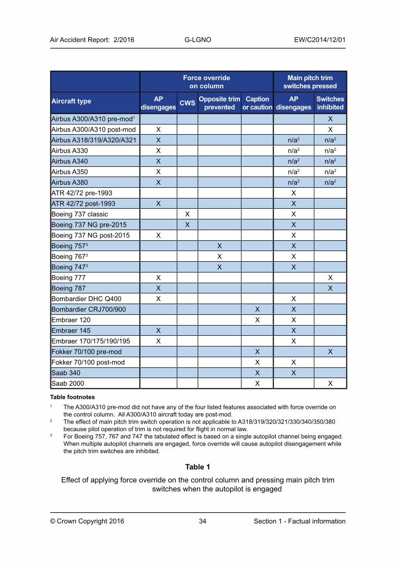
The AAIB conducted a survey of the autopilot systems of other commercial aircraft types to determine if any other systems shared these three attributes. A summary of the findings is shown in Table 1, which does not list all current in-service commercial aircraft.
On all the fly-by-wire Airbus types: A318, A319, A320, A321, A330, A340, A350 and A380, applying force above a certain threshold to the sidestick control causes the autopilot to disengage. These aircraft have auto-trim during manual flight so there are no pitch trim switches on the sidestick. There is a pitch trim wheel on A318/A319/A320/A321/A330/A340 which is used to set trim before takeoff but it is not used in the air unless there is a failure causing a loss of auto-trim. Moving the trim wheel causes the autopilot to disengage. On the A350 and A380 the pitch trim wheel has been replaced with pitch trim switches which only operate on the ground and in ‘direct law’26.
26 ‘Direct law’ is a reversionary flight control law following system failures. The autopilot on A350 and A380 will not operate in direct law.
32
Air Accident Report: 2/2016 G-LGNO EW/C2014/12/01
© Crown Copyright 2016 Section 1 - Factual information
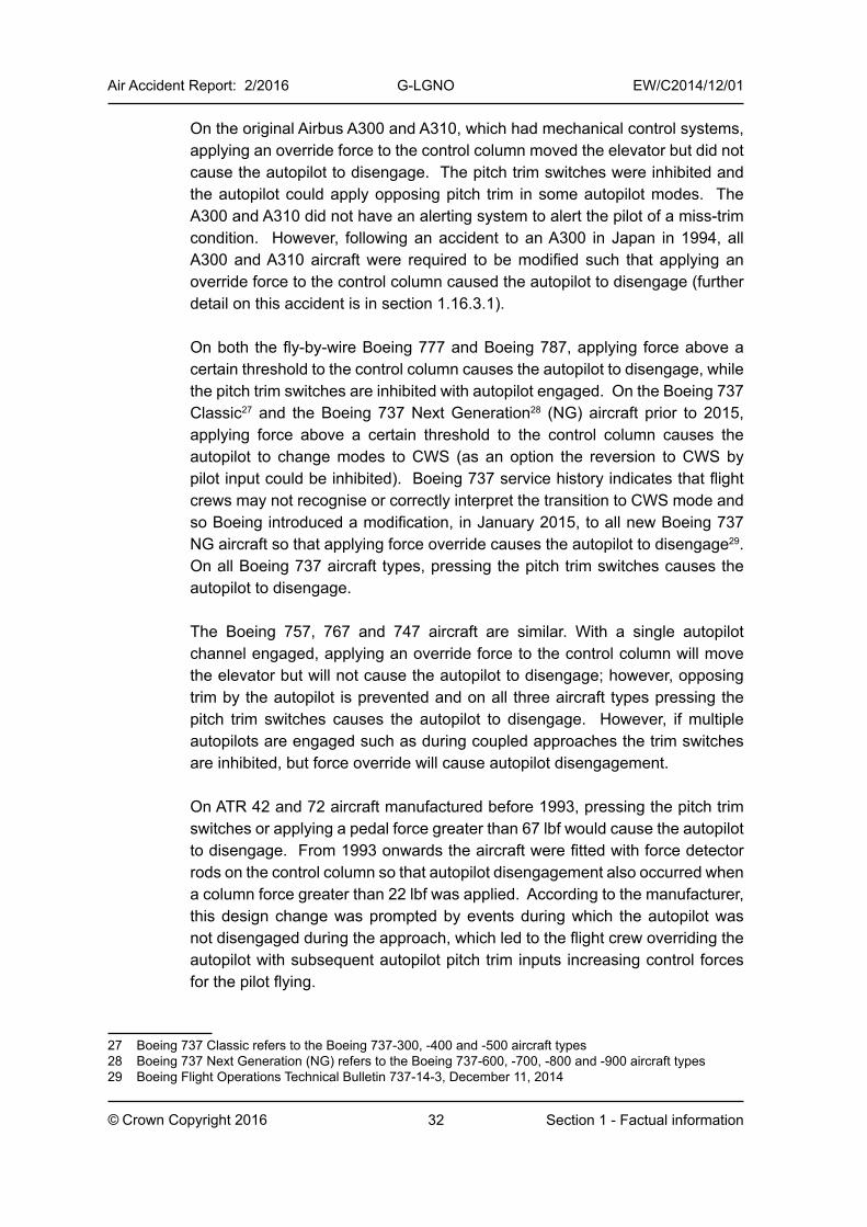
On the original Airbus A300 and A310, which had mechanical control systems, applying an override force to the control column moved the elevator but did not cause the autopilot to disengage. The pitch trim switches were inhibited and the autopilot could apply opposing pitch trim in some autopilot modes. The A300 and A310 did not have an alerting system to alert the pilot of a miss-trim condition. However, following an accident to an A300 in Japan in 1994, all A300 and A310 aircraft were required to be modified such that applying an override force to the control column caused the autopilot to disengage (further detail on this accident is in section 1.16.3.1).
On both the fly-by-wire Boeing 777 and Boeing 787, applying force above a certain threshold to the control column causes the autopilot to disengage, while the pitch trim switches are inhibited with autopilot engaged. On the Boeing 737 Classic27 and the Boeing 737 Next Generation28 (NG) aircraft prior to 2015, applying force above a certain threshold to the control column causes the autopilot to change modes to CWS (as an option the reversion to CWS by pilot input could be inhibited). Boeing 737 service history indicates that flight crews may not recognise or correctly interpret the transition to CWS mode and so Boeing introduced a modification, in January 2015, to all new Boeing 737 NG aircraft so that applying force override causes the autopilot to disengage29. On all Boeing 737 aircraft types, pressing the pitch trim switches causes the autopilot to disengage.
The Boeing 757, 767 and 747 aircraft are similar. With a single autopilot channel engaged, applying an override force to the control column will move the elevator but will not cause the autopilot to disengage; however, opposing trim by the autopilot is prevented and on all three aircraft types pressing the pitch trim switches causes the autopilot to disengage. However, if multiple autopilots are engaged such as during coupled approaches the trim switches are inhibited, but force override will cause autopilot disengagement.
On ATR 42 and 72 aircraft manufactured before 1993, pressing the pitch trim switches or applying a pedal force greater than 67 lbf would cause the autopilot to disengage. From 1993 onwards the aircraft were fitted with force detector rods on the control column so that autopilot disengagement also occurred when a column force greater than 22 lbf was applied. According to the manufacturer, this design change was prompted by events during which the autopilot was not disengaged during the approach, which led to the flight crew overriding the autopilot with subsequent autopilot pitch trim inputs increasing control forces for the pilot flying.
27 Boeing 737 Classic refers to the Boeing 737-300, -400 and -500 aircraft types28 Boeing 737 Next Generation (NG) refers to the Boeing 737-600, -700, -800 and -900 aircraft types29 Boeing Flight Operations Technical Bulletin 737-14-3, December 11, 2014
33
Air Accident Report: 2/2016 G-LGNO EW/C2014/12/01
© Crown Copyright 2016 Section 1 - Factual information
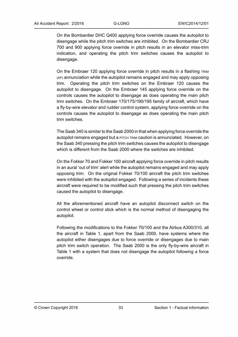
On the Bombardier DHC Q400 applying force override causes the autopilot to disengage while the pitch trim switches are inhibited. On the Bombardier CRJ 700 and 900 applying force override in pitch results in an elevator miss-trim indication, and operating the pitch trim switches causes the autopilot to disengage.
On the Embraer 120 applying force override in pitch results in a flashing trim (ap) annunciation while the autopilot remains engaged and may apply opposing trim. Operating the pitch trim switches on the Embraer 120 causes the autopilot to disengage. On the Embraer 145 applying force override on the controls causes the autopilot to disengage as does operating the main pitch trim switches. On the Embraer 170/175/190/195 family of aircraft, which have a fly-by-wire elevator and rudder control system, applying force override on the controls causes the autopilot to disengage as does operating the main pitch trim switches.
The Saab 340 is similar to the Saab 2000 in that when applying force override the autopilot remains engaged but a pitch trim caution is annunciated. However, on the Saab 340 pressing the pitch trim switches causes the autopilot to disengage which is different from the Saab 2000 where the switches are inhibited.
On the Fokker 70 and Fokker 100 aircraft applying force override in pitch results in an aural ‘out of trim’ alert while the autopilot remains engaged and may apply opposing trim. On the original Fokker 70/100 aircraft the pitch trim switches were inhibited with the autopilot engaged. Following a series of incidents these aircraft were required to be modified such that pressing the pitch trim switches caused the autopilot to disengage.
All the aforementioned aircraft have an autopilot disconnect switch on the control wheel or control stick which is the normal method of disengaging the autopilot.
Following the modifications to the Fokker 70/100 and the Airbus A300/310, all the aircraft in Table 1, apart from the Saab 2000, have systems where the autopilot either disengages due to force override or disengages due to main pitch trim switch operation. The Saab 2000 is the only fly-by-wire aircraft in Table 1 with a system that does not disengage the autopilot following a force override.
34
Air Accident Report: 2/2016 G-LGNO EW/C2014/12/01
© Crown Copyright 2016 Section 1 - Factual information
Force override on column
Main pitch trim switches pressed
Aircraft type AP disengages CWS Opposite trim
preventedCaption
or cautionAP
disengagesSwitches inhibited
Airbus A300/A310 pre-mod1 XAirbus A300/A310 post-mod X XAirbus A318/319/A320/A321 X n/a2 n/a2
Airbus A330 X n/a2 n/a2
Airbus A340 X n/a2 n/a2
Airbus A350 X n/a2 n/a2
Airbus A380 X n/a2 n/a2
ATR 42/72 pre-1993 XATR 42/72 post-1993 X XBoeing 737 classic X XBoeing 737 NG pre-2015 X XBoeing 737 NG post-2015 X XBoeing 7573 X XBoeing 7673 X XBoeing 7473 X XBoeing 777 X XBoeing 787 X XBombardier DHC Q400 X XBombardier CRJ700/900 X XEmbraer 120 X XEmbraer 145 X XEmbraer 170/175/190/195 X XFokker 70/100 pre-mod X XFokker 70/100 post-mod X XSaab 340 X XSaab 2000 X X
Table footnotes1 The A300/A310 pre-mod did not have any of the four listed features associated with force override on
the control column. All A300/A310 aircraft today are post-mod.2 The effect of main pitch trim switch operation is not applicable to A318/319/320/321/330/340/350/380
because pilot operation of trim is not required for flight in normal law.3 For Boeing 757, 767 and 747 the tabulated effect is based on a single autopilot channel being engaged.
When multiple autopilot channels are engaged, force override will cause autopilot disengagement while the pitch trim switches are inhibited.
Table 1
Effect of applying force override on the control column and pressing main pitch trim switches when the autopilot is engaged
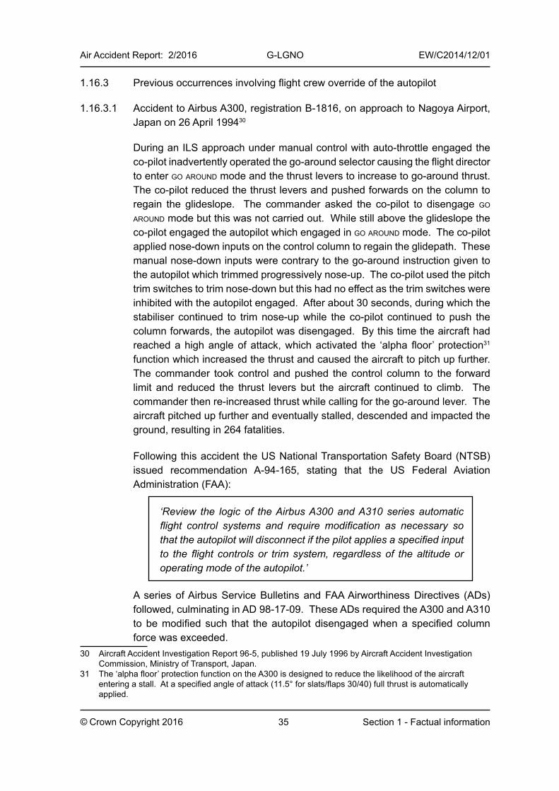
35
Air Accident Report: 2/2016 G-LGNO EW/C2014/12/01
© Crown Copyright 2016 Section 1 - Factual information
1.16.3 Previous occurrences involving flight crew override of the autopilot
1.16.3.1 Accident to Airbus A300, registration B-1816, on approach to Nagoya Airport, Japan on 26 April 199430
During an ILS approach under manual control with auto-throttle engaged the co-pilot inadvertently operated the go-around selector causing the flight director to enter go around mode and the thrust levers to increase to go-around thrust. The co-pilot reduced the thrust levers and pushed forwards on the column to regain the glideslope. The commander asked the co-pilot to disengage go around mode but this was not carried out. While still above the glideslope the co-pilot engaged the autopilot which engaged in go around mode. The co-pilot applied nose-down inputs on the control column to regain the glidepath. These manual nose-down inputs were contrary to the go-around instruction given to the autopilot which trimmed progressively nose-up. The co-pilot used the pitch trim switches to trim nose-down but this had no effect as the trim switches were inhibited with the autopilot engaged. After about 30 seconds, during which the stabiliser continued to trim nose-up while the co-pilot continued to push the column forwards, the autopilot was disengaged. By this time the aircraft had reached a high angle of attack, which activated the ‘alpha floor’ protection31 function which increased the thrust and caused the aircraft to pitch up further. The commander took control and pushed the control column to the forward limit and reduced the thrust levers but the aircraft continued to climb. The commander then re-increased thrust while calling for the go-around lever. The aircraft pitched up further and eventually stalled, descended and impacted the ground, resulting in 264 fatalities.
Following this accident the US National Transportation Safety Board (NTSB) issued recommendation A-94-165, stating that the US Federal Aviation Administration (FAA):
‘Review the logic of the Airbus A300 and A310 series automatic flight control systems and require modification as necessary so that the autopilot will disconnect if the pilot applies a specified input to the flight controls or trim system, regardless of the altitude or operating mode of the autopilot.’
A series of Airbus Service Bulletins and FAA Airworthiness Directives (ADs) followed, culminating in AD 98-17-09. These ADs required the A300 and A310 to be modified such that the autopilot disengaged when a specified column force was exceeded.
30 Aircraft Accident Investigation Report 96-5, published 19 July 1996 by Aircraft Accident Investigation Commission, Ministry of Transport, Japan.
31 The ‘alpha floor’ protection function on the A300 is designed to reduce the likelihood of the aircraft entering a stall. At a specified angle of attack (11.5° for slats/flaps 30/40) full thrust is automatically applied.
36
Air Accident Report: 2/2016 G-LGNO EW/C2014/12/01
© Crown Copyright 2016 Section 1 - Factual information
1.16.3.2 Serious incident to Fokker F28 Mark 0100 (Fokker 100), registration G-BYDN, on approach to Paris Charles de Gaulle Airport, France on 3 November 200032
The incident began when the aircraft started to oscillate gently in pitch while in level flight at FL110 with the autopilot engaged. This pitch oscillation was the consequence of an elevator restriction which was probably caused by ice accretion on the servo capstan. The autopilot was unable to move the elevator so it was trying to maintain level flight using the stabiliser which was resulting in the aircraft undershooting and overshooting its target altitude. The co-pilot disengaged the autopilot and took control but he could only move the control column about 2 cm fore and aft which reduced to no movement. The commander took control and confirmed that the control column had jammed, but by exerting a large force he was able to free the controls partially. The crew declared a MAYDAY and at about this time the autopilot was engaged, although neither pilot could recall making this selection or noticing that the autopilot was engaged. The aircraft then began to pitch up so the crew pushed the column forwards. As the aircraft decelerated both pilots needed to apply almost full forward control column to maintain level flight. Without the crew realising it the ice had cleared but they were now fighting the autopilot which was trimming the stabiliser nose-up. The commander instructed the cabin crew to move passengers from the rear of the aircraft to fill up all the seats at the front to assist in pitching the aircraft nose-down. This was accomplished but still almost full forward column was required.
At various points during the incident the commander had operated the pitch trim switches but these had not had any effect because the trim switches were inhibited with the autopilot engaged. He then tried moving the manual trim wheel which caused the autopilot to disengage and he was able to trim the aircraft nose-down and re-establish full control. A normal landing was carried out.
An investigation by the Civil Aviation Authority of the Netherlands (CAA-NL) revealed that as of 14 July 2006 there had been at least 10 reported events on Fokker 70 (F28 Mark 0070) and Fokker 100 (F28 Mark 0100) aircraft where the flight crew manually overpowered the autopilot, inadvertently neglecting to disengage the autopilot. Detailed investigation of these incidents revealed that this usually occurred in a high workload environment that demanded immediate manual control of the aircraft by the pilot flying. If the autopilot is not disengaged the Automatic Flight Control and Augmentation System (AFCAS) auto-trims in the opposite direction of the manual inputs, causing very high control forces. The CAA-NL stated in Airworthiness Directive NL-2006-1033 that:
32 AAIB Monthly Bulletin 8/2001.33 Airworthiness Directive NL-2006-010 was published on 14 July 2006 and was applicable to Fokker 70
and Fokker 100 aircraft.
37
Air Accident Report: 2/2016 G-LGNO EW/C2014/12/01
© Crown Copyright 2016 Section 1 - Factual information
‘This condition, if not corrected, could cause the stabilizer to move to an extreme out-of-trim position, creating the (remote) possibility of loss of control of the aircraft, due to the extreme control loads. In the original design of AFCAS, operation of the control wheel-mounted stabilizer trim switches has no effect when the autopilot is engaged. Based on the assumption that stabilizer trim switches will be operated by the pilot flying when encountering high control forces, an Autopilot Disconnect Unit has been developed that disconnects the autopilot when the stabilizer trim switches are operated. Since a potentially unsafe condition has been identified that may exist or develop on aircraft of this type design, this Airworthiness Directive requires the installation of Autopilot Disconnect Units and associated wiring changes.’
The modification required by this AD caused the autopilot to disengage, with associated aural and visual alerts, if the pitch trim switches were operated for more than 1.5 seconds. The compliance time for the AD was 36 months. As of April 2015 Fokker reported that they have not received any further reports of incidents involving overpowering of the autopilot since the modification was introduced.
1.16.3.3 Serious incident to Cessna 550 Citation II, registration G-JBIZ, on approach to Edinburgh Airport, UK on 14 March 200834
During the climb after departure the air duct o’heat caption illuminated intermittently. During the descent, with autopilot engaged, the flt/hr equip cool circuit breaker tripped. The flight crew were very concerned about the state of the aircraft and wanted to land as soon as possible. They subsequently encountered a problem with the air conditioning system temperature control. The commander recalled making an autopilot selection and was surprised when the autopilot did not respond. He noticed that the autopilot and yaw damper engaged lights were off, but there had been no visual or aural annunciation that the autopilot had disengaged. The aircraft was not fitted with an FDR but it was probable that the autopilot was still engaged but the ac switch circuit breaker had also tripped which removed power from the autopilot and yaw damper-engaged switch lights. Believing that the autopilot was disengaged the commander tried the controls but felt that they were “unresponsive and very stiff”; this was because he was feeling the autopilot servo resistance. He encountered further control difficulties as the aircraft slowed and felt that he could only maintain control at a minimum of 220 kt, so he planned a high speed approach maintaining 200 kt to the runway threshold and touching down at 193 kt. With maximum braking applied the aircraft stopped 50 m from the end of the runway. Subsequent examination of the aircraft did not reveal any
34 AAIB Monthly Bulletin 1/2010.
38
Air Accident Report: 2/2016 G-LGNO EW/C2014/12/01
© Crown Copyright 2016 Section 1 - Factual information
defects that would explain a control problem. On the Cessna 550 pressing the pitch trim switches causes the autopilot to disengage but because of the lack of recorded data it was not clear if these had been pressed.
1.16.4 Previous serious incident involving a significant out-of-trim condition
The serious incident to Boeing 737-300, registration G-THOF, on approach to Bournemouth Airport, UK on 23 September 200735, did not involve the flight crew overriding the autopilot but resulted in a significant out-of-trim condition.
During a decelerating ILS approach with the autopilot engaged and the thrust levers at idle, the autothrottle disengaged without the flight crew being aware. The airspeed reduced to 110 kt (25 kt below the final approach speed) before the commander began recovery actions, moving the thrust levers forward and initiating a go-around. The stall warning stick shaker activated and the thrust levers were moved fully forward. The autopilot mode changed from localiser and glideslope to ‘control wheel steering’ and then it was disengaged. During subsequent manoeuvring the flight crew had difficulty controlling the pitch attitude of the aircraft because the autopilot had trimmed the stabiliser significantly nose-up during the approach while it was trying to maintain the glideslope with insufficient thrust. Full thrust from the underslung engines was providing additional pitch-up moment. As the aircraft pitched up beyond 20° the commander applied full forward control column and held it there for a period of 30 seconds. The co-pilot also applied full forward control column. During this period neither pilot activated the pitch trim switches. The aircraft stalled, reaching a maximum nose-up pitch attitude of 44° and a minimum airspeed of 82 kt. The pitch trim switches were first used 50 seconds after full forward control column was first applied. The aircraft was recovered to level flight and landed normally.
1.16.5 FAA survey of aircraft without autopilot disengagement during flight crew override
In the lead-up to the new autopilot certification requirements the FAA carried out a survey of many major aeroplane manufacturers with aeroplane models common to the US fleet: Boeing, Airbus, Bombardier, Gulfstream, Embraer, ATR, and Dassault. The survey did not include the Saab 2000 or the Fokker 70/100. For all the aircraft surveyed which did not have automatic autopilot disengagement during force override, the autopilot either disengaged due to pitch trim switch operation or had a type of cut-out system which either stopped trimming or disengaged the autopilot when it detected manual control inputs opposing the trim commands.
35 AAIB Formal Report 3/2009.
39
Air Accident Report: 2/2016 G-LGNO EW/C2014/12/01
© Crown Copyright 2016 Section 1 - Factual information
1.17 Organisational and management information
Not relevant.
1.18 Additional information
1.18.1 Human performance
1.18.1.1 Identification of flight control malfunctions
In an aircraft with purely mechanical flying controls, a jammed flight control can be identified by resistance to movement of the control wheel or column. Failure of a control linkage will be apparent as the control will move without the usual resistance. In either case, the absence of the usual aircraft response to an input will be apparent. In this control system, the ‘loop’ from pilot input, to response felt through the controls, to aircraft response, is complete.
In an aircraft with powered or fly-by-wire controls, and without any physical feedback, it may be harder to determine a malfunction because effect of control inputs can only be assessed from aircraft response. In manoeuvring flight or turbulence, this assessment may be more difficult.
In the Saab 2000, the forces required to achieve particular control column displacement are greater when the autopilot is engaged, but this is not a usual mode of operation and pilots are unlikely to be familiar with it. A pilot feeling abnormal control resistance may not readily determine that the reason for the unusual forces is that the autopilot is engaged.
Mental models are developed by experience and/or training, and more experience leads to more detailed mental models. Mental models guide interaction with systems: an accurate mental model can facilitate good performance, but poor mental models can lead to misunderstanding of system functioning, increasing the risk of error. Designers can promote good mental models by optimising feedback, for example by providing indicators of system status and performance which are easily assimilated, even under stress.
Automation surprise36 can occur if the autopilot does not behave as expected, for example if the system remains engaged when the flight crew believes it is not. Clear feedback of the system’s status can help to prevent this inconsistency.
Stress, which might be experienced in the moments after a lightning strike, leads to an increase in physiological arousal. This may lead to ‘cognitive tunnelling’, in which individuals exhibit a tendency to focus on a small number
36 Sarter, N. B., & Woods, D. D. (1995). How in the world did we ever get into that mode? Mode error and awareness in supervisory control. Human Factors, 37(1), 5-19.
40
Air Accident Report: 2/2016 G-LGNO EW/C2014/12/01
© Crown Copyright 2016 Section 1 - Factual information
of the most salient or expected information, and only information that supports the prevailing understanding of the situation may be processed. Cognitive tunnelling not only affects perception of visual signals, it can also affect auditory processing at times of high cognitive load; this is ‘inattentional deafness’. Clear and prominent status indicators can assist.
The results from a study on ‘inattentional deafness’ in pilots in a cockpit environment were published in a paper entitled ‘Failure to Detect Critical Auditory Alerts in the Cockpit: Evidence for Inattentional Deafness’37. In this study 28 pilots of different experience levels were placed in a full motion flight simulator. They were given time to practise landings and then told to expect one of 5 different events to occur including an antiskid failure, an engine failure, a ground proximity warning and a landing gear failure. The aural warnings and visual indications associated with these conditions were shown to them. All the pilots were then given the landing gear failure scenario. Half the pilots were also given a windshear scenario (to simulate high workload) and the other half were not (to simulate normal workload). Of the pilots who were given the windshear scenario 57% failed to detect the aural gear failure warning. Of the pilots who were given the non-windshear scenario all of them detected the aural gear failure warning.
37 Dehais, Causse, Vachon, Regis, Menant & Tremblay (2013). Failure to Detect Critical Auditory Alerts in the Cockpit: Evidence for Inattentional Deafness. Human Factors: The Journal of the Human Factors and Ergonomics Society (published online 11 November 2013). http://hfs.sagepub.com/
41© Crown Copyright 2016
Air Accident Report: 2/2016 G-LGNO EW/C2014/12/01
Section 2 - Analysis
2 Analysis
2.1 Aircraft examination
The aircraft was struck by lightning that caused only minor damage to the radome and APU exhaust. Functional tests, and inspections of the elevator control system and autopilot system, did not reveal any faults. Evidence from the manufacturer’s simulation work indicated that the aircraft had responded as expected to the recorded control deflections. The reason for the high control forces experienced by the commander was a combination of the additional 25 lbf and 50 lbf required to override the autopilot pitch and roll servos respectively, and the additional aft column deflections required to counter the autopilot’s nose-down pitch trim inputs.
A download of the fault history, confirmed by FDR data, revealed that FCC 2 had caused the autopilot to disengage at 1913 hrs. The autopilot had disengaged because FCC 2 had missed data or received bad data from ADC 2 for a period of at least 99 ms. There were no subsequent in-flight ADC faults to March 2015 so ADC 2 was not removed for further investigation.
No technical faults occurred during the incident other than the brief ADC fault.
2.2 Aircraft response during the incident
After the lightning strike the aircraft climbed from 2,000 ft to 4,000 ft amsl, but there were two brief descents during this period. The ARES modelling replicated these two brief descents and they were the result of the changes in pitch attitude which were caused by the varying control column position. The control column position did not change in a linear manner; it oscillated fore and aft while moving in an overall aft direction. As the control column was relaxed the aircraft pitched nose-down into a brief descent because the pitch trim was able to overcome the column inputs. Shortly after reaching 4,000 ft amsl the control column was fully aft while the pitch trim was almost fully nose-down. The airspeed also increased and the pitch trim authority became greater than the authority from fully-aft control column causing the aircraft to pitch nose-down and enter a steep descent which could not be arrested. However, when the autopilot automatically disengaged due to the ADC 2 fault, the nose-down pitch trim stopped and the commander’s subsequent pitch trim switch inputs started to reduce the nose-down pitch trim causing the aircraft to start pitching up.
The autopilot disengaged at a 10° nose-down pitch attitude due to the ADC 2 fault. If this had not occurred the autopilot would have disengaged when the aircraft reached the autopilot pitch limit of 17° nose-down.
42© Crown Copyright 2016
Air Accident Report: 2/2016 G-LGNO EW/C2014/12/01
Section 2 - Analysis
2.3 Operation of the aircraft
Although the incident was precipitated by the triggered lightning strike, several pre-existing factors may have had an influence.
Although both pilots were qualified on type, they did not have extensive experience of the Saab 2000. However, they were not ‘inexperienced’ in the context of the requirements in the operator’s operations manual, and nothing prohibited them flying together.
The weather in Sumburgh placed additional demands upon the operation, but the normal commercial practice of loading ‘round trip’ fuel provided some mitigation, and the flight crew had discussed the forecasts prior to their first return trip to Sumburgh earlier that day. Although it was windy and turbulent, with low cloud and rain, the weather did not preclude an ILS approach and landing.
The information that the Sumburgh ATIS antenna had been struck by lightning provided a reminder to the flight crew that lightning might be encountered. The commander expected that a lightning strike would likely cause momentary loss of the engine-driven generators and that this would result in loss of the autopilot.
The operations manual provided comprehensive guidance on flight near thunderstorms but it did not offer guidance relevant to triggered lightning strikes. Previous events illustrated the possible catastrophic effects of triggered lightning on helicopter operations, but no similar evidence was found relating to fixed-wing flying.
There were indications of an increase in stress evident in the commander’s actions before the lightning strike. Although he was pilot flying, he made the transmission announcing the intended manoeuvre away from the localiser himself, when the normal operating procedure would have been for the co-pilot, as pilot monitoring, to do this. Although there are circumstances in which action needs to be taken instantly and such deviation from usual procedures is appropriate, the circumstances in which this occurred do not appear to have been especially urgent. The commander’s decision to make the transmission himself may indicate that he was under an increased level of stress and wanted to resolve the situation rapidly. Deviation from procedures can also place stress upon the monitoring pilot.
Notwithstanding the additional stress under which the commander was operating, and a possibly elevated level of stress in the case of the co-pilot, the flight crew were behaving normally prior to the lightning strike. Their cognitive
43© Crown Copyright 2016
Air Accident Report: 2/2016 G-LGNO EW/C2014/12/01
Section 2 - Analysis
functioning appeared to be intact, they were responsive to cues presented to them, and they were communicating and comparing their respective mental models. Thus the behaviour that followed, and in particular their response to the lightning strike itself, also appears consistent with normal human performance.
The lightning strike caused the commander to utter an expletive and cease transmitting to ATC, which accords with the unpleasant and surprising nature of lightning strike events. His next action, to begin making manual inputs on the flying controls, appears to have been instinctive and may have been based on his previous assumption that the autopilot would disconnect when lightning struck. The next events were a consequence of his inputs and their interaction with the aircraft’s systems.
Neither the manual pitch inputs, nor action on the pitch trim switches, caused the autopilot to disengage. The autopilot, sensing that the aircraft was now above the selected altitude of 2,000 ft amsl, began applying nose-down pitch to regain that altitude. Because the autopilot was still engaged, the control forces the commander experienced (opposing his inputs) were higher than usual for a given column displacement, and he identified that the aircraft did not feel normal. He may have attributed this to a flight control malfunction caused by the lightning strike.
Once the discrepancy between the commander’s control inputs and their apparent consequences was identified, the co-pilot’s inputs added a further influence to the feedback which the commander was experiencing through his controls. The co-pilot’s own experience, sensing the control response as inputs were made, would also not have been in line with expectations.
The AP pitch and roll mistrim indications, presented on the PFDs, were not acted upon. The commander was not aware of the meaning of these presentations, and the co-pilot was not certain, retrospectively, whether the familiar ‘P’ and ‘R’ annunciations or other similar captions had been seen.
Pilots who are experiencing difficulty simply in achieving the desired flight path may accord lower priorities to non-handling tasks, at least until the flight path is under control. Their ability to seek and process information, and then analyse it and diagnose the root cause of their difficulty may be impaired. There is uncertainty over the effectiveness of simulator training in altering the fundamental behaviour exhibited by pilots under such stress. Previous regulatory action, which required modification of other aircraft types to address similarly confusing and stressful conditions, is consistent with this conclusion.
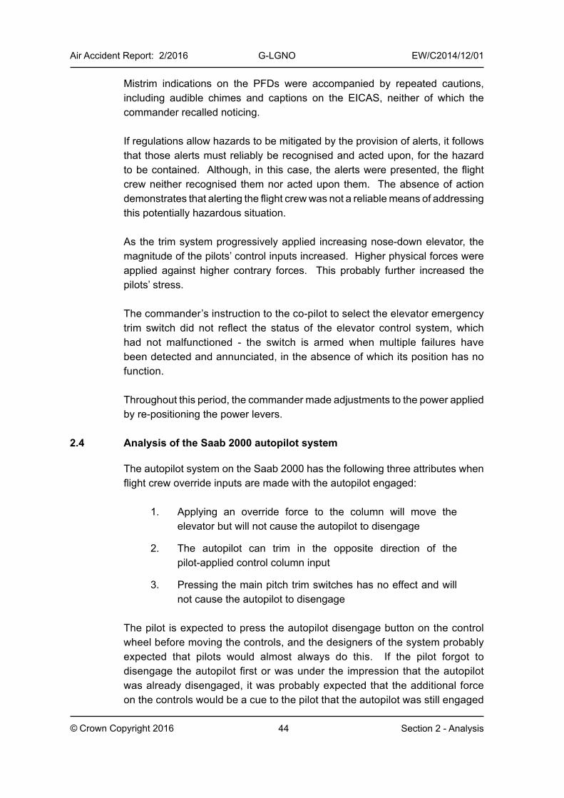
44© Crown Copyright 2016
Air Accident Report: 2/2016 G-LGNO EW/C2014/12/01
Section 2 - Analysis
Mistrim indications on the PFDs were accompanied by repeated cautions, including audible chimes and captions on the EICAS, neither of which the commander recalled noticing.
If regulations allow hazards to be mitigated by the provision of alerts, it follows that those alerts must reliably be recognised and acted upon, for the hazard to be contained. Although, in this case, the alerts were presented, the flight crew neither recognised them nor acted upon them. The absence of action demonstrates that alerting the flight crew was not a reliable means of addressing this potentially hazardous situation.
As the trim system progressively applied increasing nose-down elevator, the magnitude of the pilots’ control inputs increased. Higher physical forces were applied against higher contrary forces. This probably further increased the pilots’ stress.
The commander’s instruction to the co-pilot to select the elevator emergency trim switch did not reflect the status of the elevator control system, which had not malfunctioned - the switch is armed when multiple failures have been detected and annunciated, in the absence of which its position has no function.
Throughout this period, the commander made adjustments to the power applied by re-positioning the power levers.
2.4 Analysis of the Saab 2000 autopilot system
The autopilot system on the Saab 2000 has the following three attributes when flight crew override inputs are made with the autopilot engaged:
1. Applying an override force to the column will move the elevator but will not cause the autopilot to disengage
2. The autopilot can trim in the opposite direction of the pilot-applied control column input
3. Pressing the main pitch trim switches has no effect and will not cause the autopilot to disengage
The pilot is expected to press the autopilot disengage button on the control wheel before moving the controls, and the designers of the system probably expected that pilots would almost always do this. If the pilot forgot to disengage the autopilot first or was under the impression that the autopilot was already disengaged, it was probably expected that the additional force on the controls would be a cue to the pilot that the autopilot was still engaged
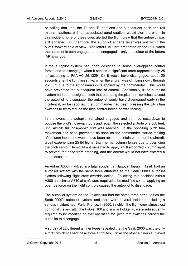
45© Crown Copyright 2016
Air Accident Report: 2/2016 G-LGNO EW/C2014/12/01
Section 2 - Analysis
or, failing that, that the ‘p’ and ‘r’ captions and subsequent pitch and roll mistrim captions, with an associated aural caution, would alert the pilot. In this incident none of these cues alerted the flight crew that the autopilot was still engaged. Furthermore, the autopilot engage lever was not within the pilots’ forward field of view. The letters ‘AP’ are presented on the PFD when the autopilot is both engaged and disengaged – only the colour of the letters ‘AP’ changes.
If the autopilot system had been designed to sense pilot-applied control forces and to disengage when it sensed a significant force (approximately 25 lbf according to FAA AC 25.1329-1C), it would have disengaged, about 20 seconds after the lightning strike, when the aircraft was climbing slowly through 2,200 ft, due to the aft column inputs applied by the commander. This would have prevented the subsequent loss of control. Additionally, if the autopilot system had been designed such that operating the pitch trim switches caused the autopilot to disengage, the autopilot would have disengaged early in the incident if, as he reported, the commander had been pressing the pitch trim switches to try to reduce the high control forces he was feeling.
In the event, the autopilot remained engaged and trimmed nose-down to oppose the pilot’s nose-up inputs and regain the selected altitude of 2,000 feet, until almost full nose-down trim was reached. If the opposing pitch trim movement had been prevented as soon as the commander started making aft column inputs, he would have been able to maintain control of the aircraft, albeit experiencing 25 lbf higher than normal column forces due to overriding the pitch servo. He would not have had to apply a full aft control column input to prevent the nose from dropping, and the aircraft would not have entered a steep descent.
An Airbus A300, involved in a fatal accident at Nagoya, Japan in 1994, had an autopilot system with the same three attributes as the Saab 2000’s autopilot system following flight crew override action. Following this accident Airbus A300 and similar A310 aircraft were required to be modified so that applying an override force on the flight controls caused the autopilot to disengage.
The autopilot system on the Fokker 100 had the same three attributes as the Saab 2000’s autopilot system, and there were several incidents including a serious incident near Paris, France, in 2000, in which the flight crew almost lost control of the aircraft. The Fokker 100 and similar Fokker 70 were subsequently required to be modified so that operating the pitch trim switches caused the autopilot to disengage.
A survey of 22 different airliner types revealed that the Saab 2000 was the only aircraft which still had these three attributes. On all the other airliners surveyed
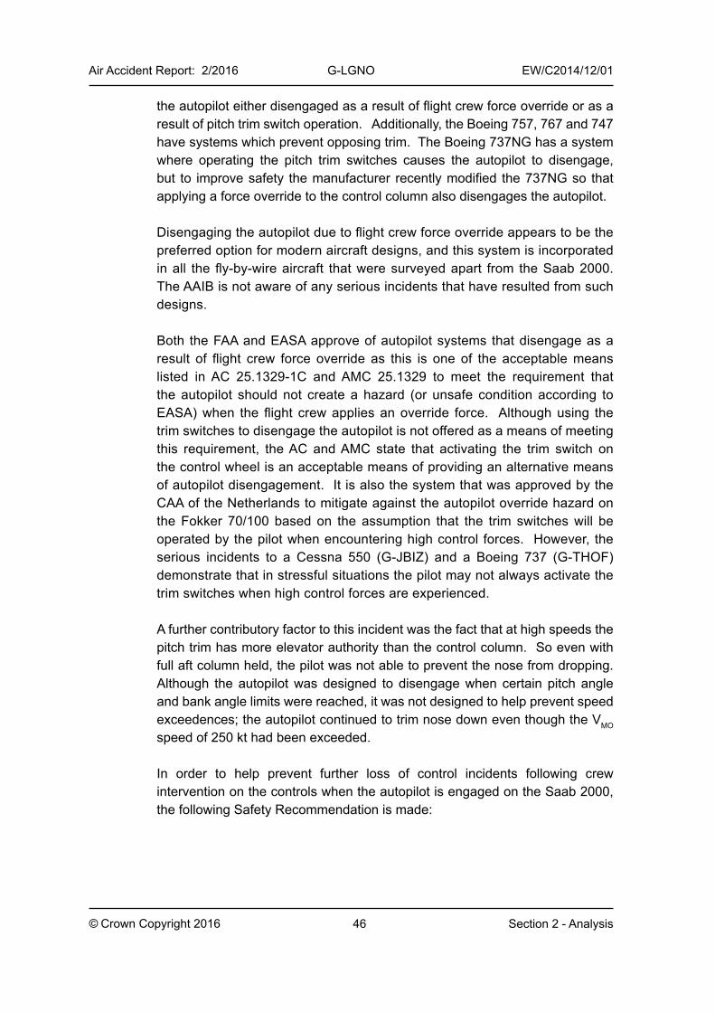
46© Crown Copyright 2016
Air Accident Report: 2/2016 G-LGNO EW/C2014/12/01
Section 2 - Analysis
the autopilot either disengaged as a result of flight crew force override or as a result of pitch trim switch operation. Additionally, the Boeing 757, 767 and 747 have systems which prevent opposing trim. The Boeing 737NG has a system where operating the pitch trim switches causes the autopilot to disengage, but to improve safety the manufacturer recently modified the 737NG so that applying a force override to the control column also disengages the autopilot.
Disengaging the autopilot due to flight crew force override appears to be the preferred option for modern aircraft designs, and this system is incorporated in all the fly-by-wire aircraft that were surveyed apart from the Saab 2000. The AAIB is not aware of any serious incidents that have resulted from such designs.
Both the FAA and EASA approve of autopilot systems that disengage as a result of flight crew force override as this is one of the acceptable means listed in AC 25.1329-1C and AMC 25.1329 to meet the requirement that the autopilot should not create a hazard (or unsafe condition according to EASA) when the flight crew applies an override force. Although using the trim switches to disengage the autopilot is not offered as a means of meeting this requirement, the AC and AMC state that activating the trim switch on the control wheel is an acceptable means of providing an alternative means of autopilot disengagement. It is also the system that was approved by the CAA of the Netherlands to mitigate against the autopilot override hazard on the Fokker 70/100 based on the assumption that the trim switches will be operated by the pilot when encountering high control forces. However, the serious incidents to a Cessna 550 (G-JBIZ) and a Boeing 737 (G-THOF) demonstrate that in stressful situations the pilot may not always activate the trim switches when high control forces are experienced.
A further contributory factor to this incident was the fact that at high speeds the pitch trim has more elevator authority than the control column. So even with full aft column held, the pilot was not able to prevent the nose from dropping. Although the autopilot was designed to disengage when certain pitch angle and bank angle limits were reached, it was not designed to help prevent speed exceedences; the autopilot continued to trim nose down even though the VMO speed of 250 kt had been exceeded.
In order to help prevent further loss of control incidents following crew intervention on the controls when the autopilot is engaged on the Saab 2000, the following Safety Recommendation is made:
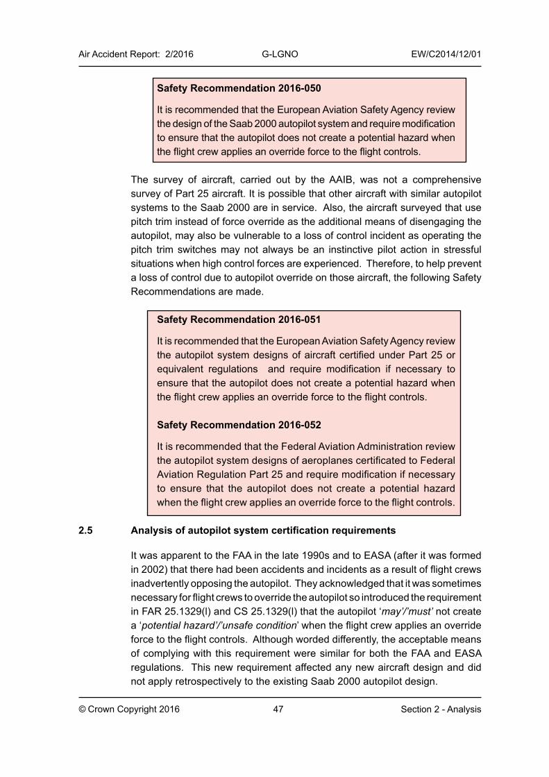
47© Crown Copyright 2016
Air Accident Report: 2/2016 G-LGNO EW/C2014/12/01
Section 2 - Analysis
Safety Recommendation 2016-050
It is recommended that the European Aviation Safety Agency review the design of the Saab 2000 autopilot system and require modification to ensure that the autopilot does not create a potential hazard when the flight crew applies an override force to the flight controls.
The survey of aircraft, carried out by the AAIB, was not a comprehensive survey of Part 25 aircraft. It is possible that other aircraft with similar autopilot systems to the Saab 2000 are in service. Also, the aircraft surveyed that use pitch trim instead of force override as the additional means of disengaging the autopilot, may also be vulnerable to a loss of control incident as operating the pitch trim switches may not always be an instinctive pilot action in stressful situations when high control forces are experienced. Therefore, to help prevent a loss of control due to autopilot override on those aircraft, the following Safety Recommendations are made.
Safety Recommendation 2016-051
It is recommended that the European Aviation Safety Agency review the autopilot system designs of aircraft certified under Part 25 or equivalent regulations and require modification if necessary to ensure that the autopilot does not create a potential hazard when the flight crew applies an override force to the flight controls.
Safety Recommendation 2016-052
It is recommended that the Federal Aviation Administration review the autopilot system designs of aeroplanes certificated to Federal Aviation Regulation Part 25 and require modification if necessary to ensure that the autopilot does not create a potential hazard when the flight crew applies an override force to the flight controls.
2.5 Analysis of autopilot system certification requirements
It was apparent to the FAA in the late 1990s and to EASA (after it was formed in 2002) that there had been accidents and incidents as a result of flight crews inadvertently opposing the autopilot. They acknowledged that it was sometimes necessary for flight crews to override the autopilot so introduced the requirement in FAR 25.1329(l) and CS 25.1329(l) that the autopilot ‘may’/’must’ not create a ‘potential hazard’/’unsafe condition’ when the flight crew applies an override force to the flight controls. Although worded differently, the acceptable means of complying with this requirement were similar for both the FAA and EASA regulations. This new requirement affected any new aircraft design and did not apply retrospectively to the existing Saab 2000 autopilot design.
48© Crown Copyright 2016
Air Accident Report: 2/2016 G-LGNO EW/C2014/12/01
Section 2 - Analysis
The FAA considered that the Saab 2000 autopilot design would not meet the current 25.1329(l) requirement, whereas EASA considered that it would need to conduct further research to determine this. According to AC and AMC 25.1329, designers could still design an autopilot that did not disengage following a significant override force, and that allowed opposing pitch trim, as long as the risk was mitigated ‘through provision of an appropriate alert and flight crew procedure.’ However, the alerting system on the Saab 2000 proved ineffective in this incident. Aural and visual alerting systems are less effective in situations when a flight crew is under stress, and if the flight crew is overriding the autopilot there is a high probability that they are doing so because of an unusual and possibly stressful situation. It is questionable whether any alerting system in this incident could have raised sufficient awareness among the flight crew to cause them to disengage the autopilot manually. It would be safer if the AC and AMC did not permit mitigation via an alerting system, and instead required the autopilot to disengage following a force override. Most new airliner designs appear to be following this route.
However, there are a number of airliners that appear to have avoided similar incidents to G-LGNO by having an autopilot system that disengages when the pitch trim switches are operated. This type of design has probably helped to avoid such incidents because it is natural for pilots to try to trim away any excessive forces they experience when inadvertently opposing the autopilot. Therefore, an autopilot system that disengages due to pitch trim switch operation may help to improve safety on those aircraft where the autopilot does not disengage due to force override. However, evidence from the Cessna 550 and Boeing 737 incidents shows that a pitch trim disengagement solution may not always be as effective in stressful situations as a force override disengagement system.
If an aircraft is designed with an autopilot that disengages due to force override then it is important to ensure that it does not disengage due to the crew inadvertently knocking the controls. For this reason the AC states that the autopilot should only disengage following a ‘significant’ force override, which should not occur from knocking the controls but would occur in a situation where a pilot wants to regain control of an aircraft quickly. The system can be designed such that control deflections below the ‘significant force’ threshold have no effect on the flight path (the Airbus fly-by-wire solution), but if the aircraft does respond below the threshold, then it is important that the autopilot does not oppose the pilot’s inputs. AC 25.1329 states that for autopilots that disengage automatically following force override, ‘the automatic trim should not run to oppose the override of the autopilot by the flightcrew.’ However, this requirement does not apply to autopilots that do not disengage following force override.
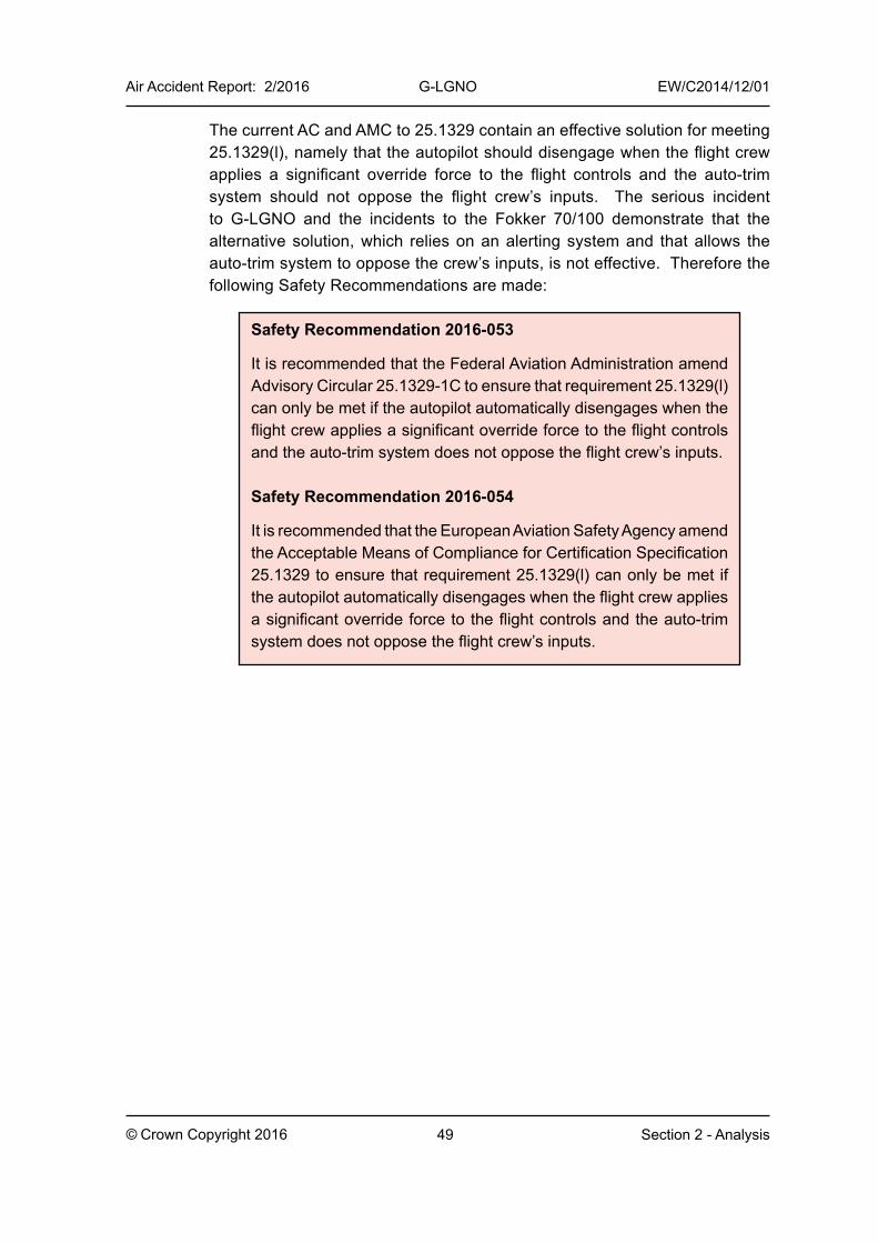
49© Crown Copyright 2016
Air Accident Report: 2/2016 G-LGNO EW/C2014/12/01
Section 2 - Analysis
The current AC and AMC to 25.1329 contain an effective solution for meeting 25.1329(l), namely that the autopilot should disengage when the flight crew applies a significant override force to the flight controls and the auto-trim system should not oppose the flight crew’s inputs. The serious incident to G-LGNO and the incidents to the Fokker 70/100 demonstrate that the alternative solution, which relies on an alerting system and that allows the auto-trim system to oppose the crew’s inputs, is not effective. Therefore the following Safety Recommendations are made:
Safety Recommendation 2016-053
It is recommended that the Federal Aviation Administration amend Advisory Circular 25.1329-1C to ensure that requirement 25.1329(l) can only be met if the autopilot automatically disengages when the flight crew applies a significant override force to the flight controls and the auto-trim system does not oppose the flight crew’s inputs.
Safety Recommendation 2016-054
It is recommended that the European Aviation Safety Agency amend the Acceptable Means of Compliance for Certification Specification 25.1329 to ensure that requirement 25.1329(l) can only be met if the autopilot automatically disengages when the flight crew applies a significant override force to the flight controls and the auto-trim system does not oppose the flight crew’s inputs.

Intentionally left blank
51
Con
clus
ions
Air Accident Report: 2/2016 G-LGNO EW/C2014/12/01
© Crown Copyright 2016 Section 3 - Conclusions
3 Conclusions
During the approach phase of a routine flight the aircraft was struck by triggered lightning. Procedures intended to prevent flight in areas where lightning may be encountered do not protect against triggered strikes. The lightning caused only minor damage to the aircraft’s radome and APU exhaust. Functional tests after the flight, and inspections of the elevator control system and autopilot system, did not reveal any faults.
Evidence from the manufacturer’s simulation work indicated that the aircraft had responded as expected to the recorded control deflections.
The commander’s actions following the lightning strike were to make manual inputs on the flying controls, which appear to have been instinctive and may have been based on his assumption that the autopilot would disconnect when lightning struck. However, the autopilot did not disconnect and was attempting to maintain a target altitude of 2,000 ft amsl by trimming nose-down while the commander was making nose-up pitch inputs. The control forces felt by the commander were higher than normal because the autopilot was opposing his inputs and he may have attributed this to a flight control malfunction caused by the lightning strike. He did not recall having seen or heard any of the aural or visual mistrim cautions which were a cue that the autopilot was still engaged. This was probably the result of cognitive tunnelling.
The commander applied and maintained full aft control column (nose-up elevator) input; however, the autopilot’s nose-down elevator trim authority exceeded the commander’s elevator nose-up authority and the aircraft pitched nose-down and descended, reaching a peak descent rate of 9,500 ft/min. The autopilot then disengaged due to an ADC fault and this allowed the commander’s nose-up pitch trim inputs to become effective. The aircraft started to pitch up just before reaching a minimum height of 1,100 ft above sea level.
If the autopilot system had been designed to sense pilot applied control forces and to disengage when it sensed a significant force (about 25 lbf according to FAA AC 25.1329-1C), the autopilot would have disengaged shortly after the aircraft climbed above 2,000 ft, in response to the aft column inputs applied by the commander. This would have prevented the subsequent loss of control. If the autopilot system had been designed such that operating the pitch trim switches resulted in autopilot disengagement, the autopilot would also have disengaged early in the sequence of events.
Of 22 airliner types surveyed, the Saab 2000 was the only type that had an autopilot which, when engaged, had the following three attributes:
52
Air Accident Report: 2/2016 G-LGNO EW/C2014/12/01
© Crown Copyright 2016 Section 3 - Conclusions
1. Applying an override force to the column will move the elevator but will not cause the autopilot to disengage
2. The autopilot can trim in the opposite direction to the pilot applied control column input
3. Pressing the main pitch trim switches has no effect and will not cause the autopilot to disengage
The Airbus A300 and Fokker 70/100 aircraft previously had such attributes, and suffered one accident (A300) and several incidents (Fokker 70/100) due to pilots overriding the autopilot; these resulted in autopilot redesigns on both aircraft types.
In order to help prevent a similar recurrence of a loss of control due to autopilot override on the Saab 2000 and other aircraft types, five Safety Recommendations are made.
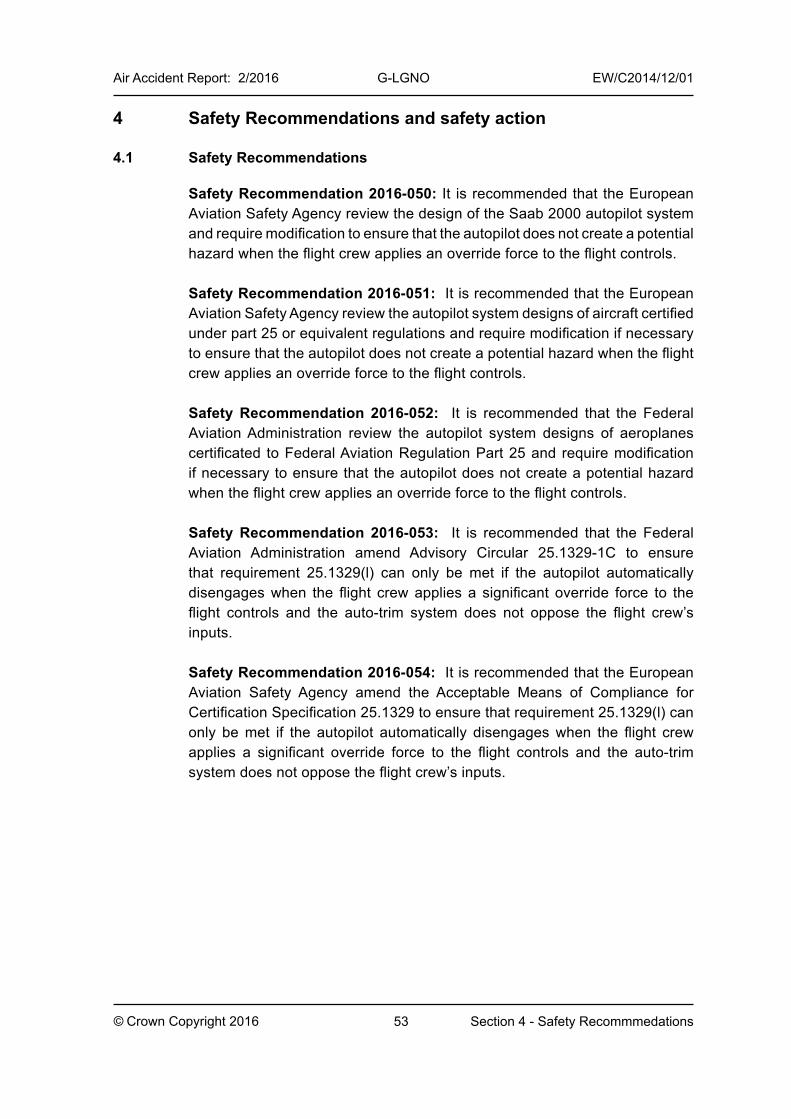
53© Crown Copyright 2016
Air Accident Report: 2/2016 G-LGNO EW/C2014/12/01
Section 4 - Safety Recommmedations
4 Safety Recommendations and safety action
4.1 Safety Recommendations
Safety Recommendation 2016-050: It is recommended that the European Aviation Safety Agency review the design of the Saab 2000 autopilot system and require modification to ensure that the autopilot does not create a potential hazard when the flight crew applies an override force to the flight controls.
Safety Recommendation 2016-051: It is recommended that the European Aviation Safety Agency review the autopilot system designs of aircraft certified under part 25 or equivalent regulations and require modification if necessary to ensure that the autopilot does not create a potential hazard when the flight crew applies an override force to the flight controls.
Safety Recommendation 2016-052: It is recommended that the Federal Aviation Administration review the autopilot system designs of aeroplanes certificated to Federal Aviation Regulation Part 25 and require modification if necessary to ensure that the autopilot does not create a potential hazard when the flight crew applies an override force to the flight controls.
Safety Recommendation 2016-053: It is recommended that the Federal Aviation Administration amend Advisory Circular 25.1329-1C to ensure that requirement 25.1329(l) can only be met if the autopilot automatically disengages when the flight crew applies a significant override force to the flight controls and the auto-trim system does not oppose the flight crew’s inputs.
Safety Recommendation 2016-054: It is recommended that the European Aviation Safety Agency amend the Acceptable Means of Compliance for Certification Specification 25.1329 to ensure that requirement 25.1329(l) can only be met if the autopilot automatically disengages when the flight crew applies a significant override force to the flight controls and the auto-trim system does not oppose the flight crew’s inputs.
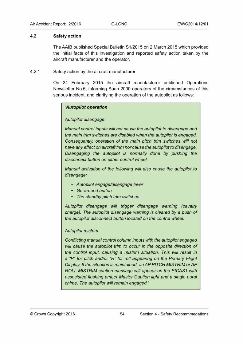
54© Crown Copyright 2016
Air Accident Report: 2/2016 G-LGNO EW/C2014/12/01
Section 4 - Safety Recommmedations
4.2 Safety action
The AAIB published Special Bulletin S1/2015 on 2 March 2015 which provided the initial facts of this investigation and reported safety action taken by the aircraft manufacturer and the operator.
4.2.1 Safety action by the aircraft manufacturer
On 24 February 2015 the aircraft manufacturer published Operations Newsletter No.6, informing Saab 2000 operators of the circumstances of this serious incident, and clarifying the operation of the autopilot as follows:
‘Autopilot operation
Autopilot disengage:
Manual control inputs will not cause the autopilot to disengage and the main trim switches are disabled when the autopilot is engaged. Consequently, operation of the main pitch trim switches will not have any effect on aircraft trim nor cause the autopilot to disengage.Disengaging the autopilot is normally done by pushing the disconnect button on either control wheel.
Manual activation of the following will also cause the autopilot to disengage:
− Autopilot engage/disengage lever− Go-around button− The standby pitch trim switches
Autopilot disengage will trigger disengage warning (cavalry charge). The autopilot disengage warning is cleared by a push of the autopilot disconnect button located on the control wheel.
Autopilot mistrim
Conflicting manual control column inputs with the autopilot engaged will cause the autopilot trim to occur in the opposite direction of the control input, causing a mistrim situation. This will result in a “P” for pitch and/or “R” for roll appearing on the Primary Flight Display. If the situation is maintained, an AP PITCH MISTRIM or AP ROLL MISTRIM caution message will appear on the EICAS1 with associated flashing amber Master Caution light and a single aural chime. The autopilot will remain engaged.’

55© Crown Copyright 2016
Air Accident Report: 2/2016 G-LGNO EW/C2014/12/01
Section 4 - Safety Recommmedations
4.2.2 Safety action by the operator
The operator put in place a number of ‘Mitigations to prevent an unsafe condition occurring when a pilot inadvertently applies an override force to the flight controls’. It provided a description of these measures as follows:
‘1. Notice to Aircrew (NOTAC)
NOTAC 123/14 was issued to all [the operator’s] SAAB 2000 pilots on 23rd December 2014 advising to ensure that the autopilot is disconnected in the event of experiencing control abnormalities:
Background
The Saab 2000 autopilot does not disconnect when overpowered or when the control wheel pitch trim switches are operated. If the autopilot is engaged and the autopilot is overpowered it is possible to fly the aircraft and not be aware that the autopilot is engaged. However, in this situation, the autopilot pitch trim will operate to compensate for pilot input and can lead to increased control forces.
Action
In the event that increased control forces are experienced, pilots should ensure that the autopilot is disengaged.
2. Pilot Briefings
On the 19th December 2014 all SAAB 2000 pilots received a briefing on the incident. These briefings were either face-to- face or via telephone and included the reasons behind the NOTAC.
3. Operator Conversion Training
Following Type Rating Training all pilots new to the SAAB 2000 undergo 8 hours of simulator conversion training on [the operator’s] procedures. All pilots are now exposed to this condition in the simulator and the corrective action required.
4. Triennial Training
All SAAB 2000 pilots are to be exposed to this condition and the corrective actions required in the simulator during recurrent training on a three yearly cycle.
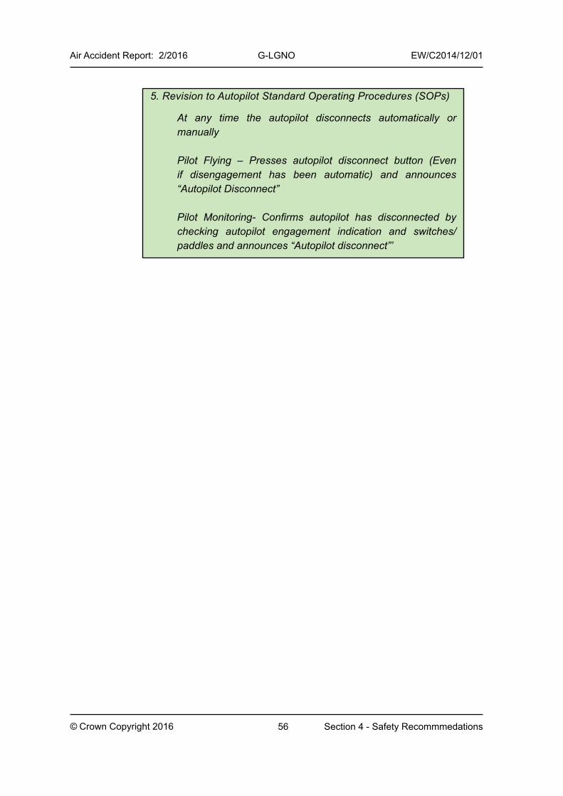
56© Crown Copyright 2016
Air Accident Report: 2/2016 G-LGNO EW/C2014/12/01
Section 4 - Safety Recommmedations
5. Revision to Autopilot Standard Operating Procedures (SOPs)
At any time the autopilot disconnects automatically or manually
Pilot Flying – Presses autopilot disconnect button (Even if disengagement has been automatic) and announces “Autopilot Disconnect”
Pilot Monitoring- Confirms autopilot has disconnected by checking autopilot engagement indication and switches/paddles and announces “Autopilot disconnect”’
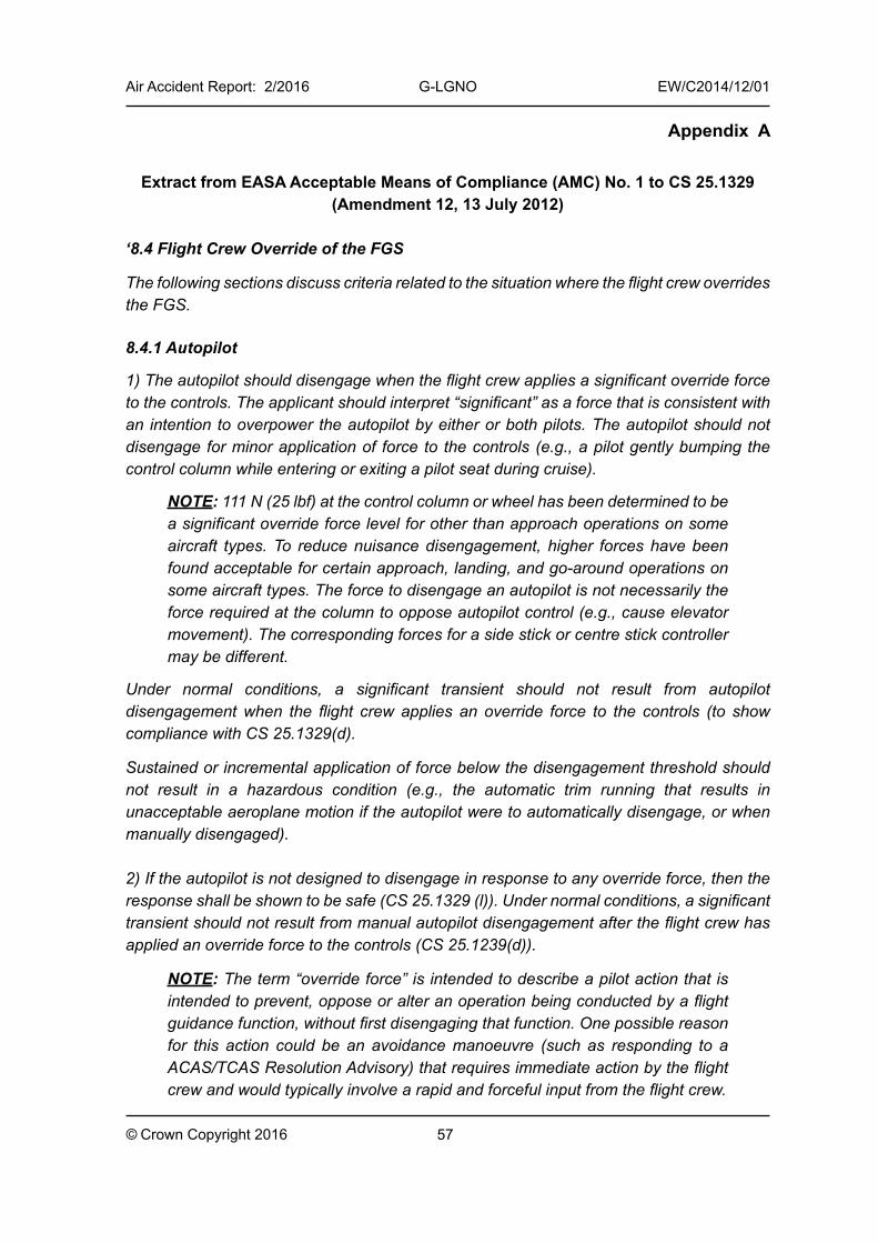
57
Air Accident Report: 2/2016 G-LGNO EW/C2014/12/01
© Crown Copyright 2016
Appendix A
Extract from EASA Acceptable Means of Compliance (AMC) No. 1 to CS 25.1329 (Amendment 12, 13 July 2012)
‘8.4 Flight Crew Override of the FGS
The following sections discuss criteria related to the situation where the flight crew overrides the FGS.
8.4.1 Autopilot
1) The autopilot should disengage when the flight crew applies a significant override force to the controls. The applicant should interpret “significant” as a force that is consistent with an intention to overpower the autopilot by either or both pilots. The autopilot should not disengage for minor application of force to the controls (e.g., a pilot gently bumping the control column while entering or exiting a pilot seat during cruise).
NOTE: 111 N (25 lbf) at the control column or wheel has been determined to be a significant override force level for other than approach operations on some aircraft types. To reduce nuisance disengagement, higher forces have been found acceptable for certain approach, landing, and go-around operations on some aircraft types. The force to disengage an autopilot is not necessarily the force required at the column to oppose autopilot control (e.g., cause elevator movement). The corresponding forces for a side stick or centre stick controller may be different.
Under normal conditions, a significant transient should not result from autopilot disengagement when the flight crew applies an override force to the controls (to show compliance with CS 25.1329(d).
Sustained or incremental application of force below the disengagement threshold should not result in a hazardous condition (e.g., the automatic trim running that results in unacceptable aeroplane motion if the autopilot were to automatically disengage, or when manually disengaged).
2) If the autopilot is not designed to disengage in response to any override force, then the response shall be shown to be safe (CS 25.1329 (l)). Under normal conditions, a significant transient should not result from manual autopilot disengagement after the flight crew has applied an override force to the controls (CS 25.1239(d)).
NOTE: The term “override force” is intended to describe a pilot action that is intended to prevent, oppose or alter an operation being conducted by a flight guidance function, without first disengaging that function. One possible reason for this action could be an avoidance manoeuvre (such as responding to a ACAS/TCAS Resolution Advisory) that requires immediate action by the flight crew and would typically involve a rapid and forceful input from the flight crew.
58
Air Accident Report: 2/2016 G-LGNO EW/C2014/12/01
© Crown Copyright 2016
Appendix A - cont
Sustained application of an override force should not result in a hazardous condition. Mitigation may be accomplished through provision of an appropriate Alert and flight crew procedure.
NOTE: The term “sustained application of override force” is intended to describe a force that is applied to the controls that may be small, slow, and sustained for some period of time. This may be due to an inadvertent crew action, or may be an intentional crew action meant to “assist” the autopilot in a particular manoeuvre. See Section 14.1.5.
NOTE: For CWS – refer to Section 11.6’
Extract from FAA AC 25.1329-1C (October 2014)
‘30. Override of the FGS.
a. General. An override of an engaged FGS function is defined as an action taken by the flightcrew intended to prevent, oppose, or alter an operation being conducted by the FGS function without first disengaging that function.
b. Autopilot override.
(1) With automatic disengagement.
(a) Override force. The autopilot should disengage when the flightcrew applies a significant override force to the controls. The applicant should interpret “significant” as a force that is consistent with an intention to overpower the autopilot by either or both pilots. The autopilot should not disengage by minor application of force to the controls, such as a pilot gently bumping the control column while entering or exiting a pilot seat during cruise.
Note: Twenty-five pounds (25 lbs) of force at the control column or wheel has been determined to be a significant override force level for other than approach operations on some aircraft types. To reduce nuisance disengagement, higher forces have been found acceptable for certain approach, landing, and go-around operations on some aircraft. The force to disengage an autopilot is not necessarily the force required at the column to oppose autopilot control, that is, to cause elevator movement. The corresponding forces for a sidestick controller may be different.
(b) Transients resulting from override. In normal operating conditions, a transient larger than a minor transient may not result from autopilot disengagement when the flightcrew applies an override force to the controls. See § 25.1329(d). Mitigation may be accomplished through provision of an appropriate alert and flightcrew procedure.
59
Air Accident Report: 2/2016 G-LGNO EW/C2014/12/01
© Crown Copyright 2016
Appendix A - cont
(c) Sustained override force below level required for automatic disconnect.
Sustained application of force below the disengagement threshold may not result in a potential hazard. See § 25.1329(l). For example, the automatic trim should not run to oppose the override of the autopilot by the flightcrew that would result in unacceptable airplane motion, if the autopilot were to automatically disengage or be manually disengaged.
(2) Without automatic disengagement.
(a) Potential hazard. If the FGS is not designed to disengage in response to any override force, then the response to an override may not result in a potential hazard. Sustained application of an override force may not result in a potential hazard, such as when the flightcrew abruptly releases the force on the controls. See § 25.1329(l). Mitigation may be accomplished through provision of an appropriate alert and flightcrew procedure.
Note: The term “sustained application of override force” is intended to describe a force that is applied to the controls, which may be small, slow, and sustained for some period of time. This may be due to an inadvertent crew action or may be an intentional crew action meant to “assist” the autopilot in a particular maneuver. (See Chapter 9, Compliance Demonstration Using Flight
Test and Simulation, paragraph 99.f, Flightcrew Override of the FGS, of this AC for more information.)
(b) Transients resulting from override. In normal operating conditions, a transient larger than a minor transient may not result from manual autopilot disengagement after the flightcrew has applied an override force to the controls. See § 25.1329(d). Mitigation may be accomplished through provision of an appropriate alert and flightcrew procedure.
Note 1: The term “override force” is intended to describe a pilot action that is intended to prevent, oppose, or alter an operation being conducted by a flight guidance function without first disengaging that function. One possible reason for this action could be an avoidance maneuver, such as responding to a traffic alert and collision avoidance system (TCAS) resolution advisory that requires immediate action by the flightcrew and would typically involve a rapid and forceful input from the flightcrew.
Note 2: For control wheel steering considerations, see Chapter 6,
Characteristics of Specific Modes, paragraph 68, Control Wheel Steering
(Control Steering through the Autopilot), of this AC.’
60
Air Accident Report: 2/2016 G-LGNO EW/C2014/12/01
© Crown Copyright 2016
Appendix B
Operator’s operations manual Part A extracts
‘8.3.8.1.1 Recommended Technique for Flying through Areas of Thunderstorm Activity
Irrespective of the equipment fitted the latest meteorological forecasts and actual weather reports should be used to plan routes along which the risk of a thunderstorm encounter is low. If, despite these precautions, the commander finds himself committed to flying through an area of thunderstorm activity, the following procedures are recommended.
a. Approaching the thunderstorms area:
i. Ensure that crew members’ and passengers’ safety belts or harnesses are firmly fastened and any loose articles are secured.
ii. One pilot should control the aeroplane and the other monitor the flight instruments and electrical supplies continuously.
iii. Select an altitude for penetration whilst ensuring adequate terrain clearance.
iv. Set the power to give the recommended speed for flight in turbulence, adjust the trim and note its position so that any excessive changes due to autopilot or mach trim can be quickly assessed.
v. Ensure that the pitot heaters are switched on.
vi. Check the operation of all anti-icing and de-icing equipment and operate all these systems in accordance with Company instructions.
vii. Disregard any radio navigation indications subject to interference from static, e.g. ADF.
viii. Turn the cockpit lighting fully on and lower the crew seats and sun visors to minimise the blinding effect of lightning flashes.
ix. Follow the recommendations of the manufacturer on the use of the flight director, autopilot and manometric locks. If these are not stated, height, mach no., rate of climb or descent and airspeed locks should be disengaged but the yaw damper(s), if fitted, should be operative.
x. Continue monitoring the weather radar in order to select the safest track for penetration.
xi. In turbine powered aeroplane switch on the continuous ignition system considering any system limitations that may exist.
xii. Avoid flying in close proximity to a thunderstorm whenever possible.
61
Air Accident Report: 2/2016 G-LGNO EW/C2014/12/01
© Crown Copyright 2016
Appendix B - cont
Within the storm area:
i. Maintain control of the aeroplane whilst concentrating on maintaining a constant pitch attitude appropriate to climb, cruise or descent, by reference to the attitude indicators, avoid harsh or excessive control movements. Do not be misled by conflicting indications on other instruments. Do not allow large attitude excursions in the rolling plane to persist.
ii. Attempt to maintain the original heading.
iii. Do not correct for altitude gained or lost through up and down draughts unless absolutely necessary.
iv. Maintain the trim settings and avoid changing the power setting except when necessary to restore margins from stall warning or high speed buffet.
v. If trim variation due to the autopilot (auto-trim) are large the autopilot should be disengaged. Movement of the mach trim, where it occurs, is however necessary and desirable. Check that the yaw-damper remains engaged.
vi. If negative G is experienced, temporary warnings (e.g. low oil pressure) may occur. These should be ignored.
vii. On no account climb in an attempt to get over the top of the storm.’
Operator’s operations manual Part B extracts
3.5 Lightning Strikes
Lightning can occur both within and away from cumulonimbus clouds, with discharges taking place either within the cloud or between neighbouring clouds. They commonly occur between a cloud and the ground and less commonly from the top of a cloud upwards. No physical danger exists to the occupants of a correctly bonded metal aircraft, but there is a danger that the disconcerting effects, particularly of dazzle, may lead to loss of control unless the pilots are fully prepared.
If flying at night when lightning occurs, all cockpit and instrument lighting should be turned on and the intensity turned up to max using the potentiometers. One of the pilots should wear dark glasses.
Direct reading magnetic compasses and magnetically slaved compasses can be severely affected by lightning strikes. Magnetic compasses should not be relied upon after an aircraft strike and should be checked as soon as possible against a runway QDM, remembering to satisfy the requirements of use of the standby compass on the deviation card.
To enable a thorough de-brief of the engineering staff, any system malfunctions or abnormalities should be noted following a lightning strike.’


Unless otherwise indicated, recommendations in this report are addressed to the appropriate regulatory authorities having responsibility for the matters with which the recommendation is concerned. It is for those authorities to decide what action is taken. In the United Kingdom the responsible authority is the Civil Aviation Authority, CAA House, 45-49 Kingsway, London WC2B 6TE or the European Aviation Safety Agency, Postfach 10 12 53, D-50452 Koeln, Germany.

Unless otherwise indicated, recommendations in this report are addressed to the appropriate regulatory authorities having responsibility for the matters with which the recommendation is concerned. It is for those authorities to decide what action is taken. In the United Kingdom the responsible authority is the Civil Aviation Authority, CAA House, 45-49 Kingsway, London WC2B 6TE or the European Aviation Safety Agency, Postfach 10 12 53, D-50452 Koeln, Germany.