Embed Size (px)
Citation preview
AA2016-9
AIRCRAFT ACCIDENT
INVESTIGATION REPORT
ASIANA AIRLINES, INC. H L 7 7 6 2
November 24, 2016
The objective of the investigation conducted by the Japan Transport Safety Board in
accordance with the Act for Establishment of the Japan Transport Safety Board and with
Annex 13 to the Convention on International Civil Aviation is to determine the causes of
an accident and damage incidental to such an accident, thereby preventing future
accidents and reducing damage. It is not the purpose of the investigation to apportion
blame or liability.
Kazuhiro Nakahashi
Chairman,
Japan Transport Safety Board
Note:
This report is a translation of the Japanese original investigation report. The text in Japanese shall
prevail in the interpretation of the report.
AIRCRAFT ACCIDENT INVESTIGATION REPORT
ASIANA AIRLINES, INC.
AIRBUS A320-200, HL7762
COLLISION WITH
THE AERONAUTICAL RADIO NAVIGATION AIDS
CAUSED BY UNDERSHOOTING
HIROSHIMA AIRPORT
AT 20:05 JST, APRIL 14, 2015
November 18, 2016
Adopted by the Japan Transport Safety Board
Chairman Kazuhiro Nakahashi
Member Toru Miyashita
Member Toshiyuki Ishikawa
Member Sadao Tamura
Member Keiji Tanaka
Member Miwa Nakanishi
SYNOPSIS
Summary of the Accident
On Tuesday, April 14, 2015, an Airbus A320-200, registered HL7762, operated by
Asiana Airlines, Inc., as the scheduled Flight 162 of the company, approached lower than
the prescribed approach path during approach to Hiroshima airport. The aircraft collided
with the Aeronautical Radio Navigation Aids located in front of the runway 28 at 20:05
JST and KST, and it touched down in front of the threshold of the runway. Subsequently,
it moved forward on the runway, and then deviated to the south side of the runway and
came to a stop inside the runway strip of the airport.
There were 81 people on board, consisting of the Pilot-in-Command (PIC), six other
crew members, a boarding mechanic and 73 passengers. Among them, 26 passengers and
two crew members, 28 people in total, were slightly injured.
The aircraft was substantially damaged, but there was no fire breakout.
Probable Causes
It is certain that when landing on runway 28 at Hiroshima airport, the aircraft
undershot and the PIC commenced executing a go-around; however, it collided with the
Aeronautical Radio Navigation Aids located in front of runway 28 threshold, just before
turning to climb.
Regarding the fact that the aircraft undershot, it is probable that there might be
following aspects in causes: The PIC continued approaching without executing a go-
around while the position of the aircraft could not be identified by visual references
which should have been in view and identified continuously at or below the approach
height threshold (Decision Altitude: DA); and as well, the first officer, as pilot-monitoring
who should have monitored meteorological conditions and flight operations, did not make
a call-out of go-around immediately when he could not see the runway at DA.
Regarding the fact that the PIC continued approaching without executing a go-
around while the position of the aircraft could not be identified by visual references
which should have been in view and identified continuously at or below DA, he did not
comply with the regulations and Standard Operating Procedures (SOP), and it is
probable that there was a background factor that the education and trainings for
compliance of rules in the company was insufficient. In addition, regarding the fact that
the first officer did not make an assertion of go-around, it is probable that the Crew
Resource Management (CRM) did not function appropriately.
Safety Recommendations
It is certain that when landing on runway 28 at Hiroshima airport, the aircraft
undershot and the Pilot-in-Command (PIC) commenced executing a go-around; however,
it collided with the Aeronautical Radio Navigation Aids located in front of runway 28
threshold, just before turning to climb.
In this accident, the PIC did not comply with the regulations and Standard
Operating Procedures (SOP): He continued approaching below the approach height
threshold (Decision Altitude: DA) without executing a go-around in a situation while the
position of the aircraft could not be identified by visual references which should have
been in view and identified continuously at or below DA. Other than that, there were
several non-compliance with regulations and SOP in his operations.
The Company, taking into account the lessons learned from the accident, should
reemphasize and reinforce the significance of compliance by flight crew members, while
reviewing company procedures and ensuring comprehensive training.
Moreover, it should surely implement the education and training that flight crew
members should refer primarily to visual references, using flight instruments as
supplementary tools appropriately, when approaching below DA.
In order to contribute to prevention of recurrence of similar accidents based on the
results of this accident investigation, Japan Transport Safety Board makes the safety
recommendations that Ministry of Land Infrastructure and Transport, Republic of Korea
should supervise Asiana Airlines, Inc. in the following items:
(1) The Company should reemphasize and reinforce the significance of compliance by
flight crew members, while reviewing company procedures and ensuring
comprehensive training.
(2) The Company should surely implement the education and training that flight
crew members should refer primarily to visual references, using flight instruments
as supplementary tools appropriately, when approaching below DA.
Abbreviations used in this report are as follows:
AIC: Aeronautical Information Circular
AIP: Aeronautical Information Publication
ALT: Altitude
AP: Autopilot
APP: Approach
APU: Auxiliary Power Unit
ARAIB: Aviation and Railway Accident Investigation Board
ASM: Airport Services Manual
ATIS: Automatic Terminal Information Service
A/THR: Auto Thrust
Baro-VNAV: Barometric Vertical Navigation
BRK: Brake
CAPT: Captain
CAT: Category
CCM: Cabin Crew Manual
CRM: Crew Resource Management
CTL: Control
CVR: Cockpit Voice Recorder
DA: Decision Altitude
DH: Decision Height
DME: Distance Measuring Equipment
EGPWS: Enhanced Ground Proximity Warning System
ENG: Engine
EVAC: Evacuation
FA: Flight Attendant
FAF: Final Approach FIX
FAP: Final Approach Point
FCOM: Flight Crew Operating Manual
FCTM: Flight Crew Training Manual
FCU: Flight Control Unit
FD: Flight Director
FDR: Flight Data Recorder
FL: Flight Level
FMA: Flight Mode Annunciator
FMGC: Flight Management Guidance Computer
FOM: Flight Operations Manual
FOQA: Flight Operations Quality Assurance
FPA: Flight Path Angle
FPV: Flight Path Vector
GND: Ground
GNSS: Global Navigation Satellite System
GPWS: Ground Proximity Warning System
GS: Ground Speed
HDG: Heading
IAF: Initial Approach Fix
ICAO: International Civil Aviation Organization
IF: Intermediate Approach Fix
ILS: Instrument Landing System
IMC: Instrument Meteorological Conditions
JST: Japan Standard Time
LGT: Light (s)
LNAV: Lateral Navigation
LOC: Localizer
MAC: Mean Aerodynamic Chord
MAHF: Missed Approach Holding Fix
MAPt: Missed Approach Point
MDA: Minimum Descent Altitude
MSL: Mean Sea Level
MSAW: Minimum Safe Altitude Warning
ND: Navigation Display
PA: Passengers Address
PAPI: Precision Approach Path Indicator
pb: push button
PF: Pilot Flying
PFD: Primary Flight Display
PIC: Pilot In Command
PM: Pilot Monitoring
POM: Pilot Operating Manual
PTT: Push To Talk
PURS: Purser
QRH: Quick Reference Handbook
RA: Radio Altitude
RDH: Reference Datum Height
RET: Retract
RFF: Rescue and Firefighting
RAIM: Receivers Autonomous Integrity Monitoring
RNAV: Area Navigation
RVR: Runway Visual Range
RWY: Runway
SALS: Simple Approach Lighting System
SDF: Step Down Fix
SOP: Standard Operating Procedures
SPD: Speed
SPLY: Supply
sw: switch
TAF: Terminal Aerodrome Forecast
TOGA: Take Off / Go Around
TRK: Track
V/DEV: Vertical Deviation
VDP: Visual Descent Point
VHF: Very High Frequency
VIS: Visibility
VMC: Visual Meteorological Conditions
VNAV: Vertical Navigation
VOR: VHF Omni-directional Radio Range
VPA: Vertical Path Angle
VS: Vertical Speed
XTK: Cross Track
Unit Conversion Table
1 ft: 0.3048 m
1 kt: 1.852 km/h(0.5144 m/s)
1 nm: 1,852 m
1 lb: 0.4536 kg
1 inHg: 33.86 hPa

Table of Content (i)
Table of Content
1. PROCESS AND PROGRESS OF INVESTIGATION ........................................... 1
1.1 Summary of the Accident ..................................................................................... 1
1.2 Outline of the Accident Investigation .................................................................. 1
1.2.1 Investigation Organization ........................................................................... 1
1.2.2 Representatives of the Relevant States ....................................................... 1
1.2.3 Implementation of the Investigation ........................................................... 1
1.2.4 Comments from the Parties Relevant to the Cause of the Accident ......... 2
1.2.5 Comments from the Relevant States ........................................................... 2
2. FACTUAL INFORMATION ................................................................................... 3
2.1 History of the Flight ............................................................................................. 3
2.1.1 History of the Flight Based on Flight Records and ATC Communication Records ..... 4
2.1.2 Statements of the Crew Members, Air Traffic Controllers and others ..... 8
2.2 Injuries to Persons .............................................................................................. 15
2.3 Damage to the Aircraft ....................................................................................... 15
2.3.1 Extent of Damage ........................................................................................ 15
2.3.2 Damages to the Aircraft Components ........................................................ 15
2.4 Information Relevant to Damaged Properties other than the Aircraft .......... 16
2.5 Personnel Information ........................................................................................ 16
2.5.1 Flight Crew Members ................................................................................. 16
2.5.2 Air Traffic Controllers ................................................................................. 17
2.6 Information Relevant to the Aircraft ................................................................. 17
2.6.1 Aircraft ......................................................................................................... 17
2.6.2 Weight and Balance .................................................................................... 18
2.7 Meteorological Information ................................................................................ 18
2.7.1 Meteorological Summary ............................................................................ 18
2.7.2 Observation Value of TAF and Aviation Weather at the Airport ............ 18
2.7.3 Meteorological Information that the Aircraft Obtained ........................... 20
2.7.4 Wind Data Before the Accident Occurred ................................................. 21
2.7.5 RVR .............................................................................................................. 22
2.7.6 Fog Generation at the Airport .................................................................... 23
2.8 Information Relevant to Aeronautical Radio Navigation Aids and Other Facilities .. 25
2.8.1 Aerodrome Lightings and others ................................................................ 25
2.8.2 Aeronautical Radio Navigation Aids and others....................................... 26
2.8.3 MSAW .......................................................................................................... 27
Table of Content (ii)
2.9 Information Relevant to the Airport and the Ground Aids ............................. 27
2.9.1 Runway and Runway strip ......................................................................... 27
2.9.2 Approach Procedure .................................................................................... 28
2.9.3 Localizer ....................................................................................................... 28
2.10 Information on the Flight Recorders ............................................................... 29
2.11 Information on the Accident Site and the Airframe ....................................... 29
2.11.1 Situation at the Accident Site .................................................................. 29
2.11.2 Details of Damage of the Airframe .......................................................... 31
2.11.3 Situation in the Cockpit and Cabin ......................................................... 33
2.11.4 Situation of Main Doorways, Emergency Exits and Evacuation Slides .. 34
2.12 Rules and Standards Relevant to Approach ................................................... 34
2.12.1 Rules of Ordinance for Enforcement of the Civil Aeronautics Act Relevant to Approach by IFR ... 34
2.12.2 Rules of Annex 6 to the Convention on International Civil Aviation (Chicago Convention) .. 35
2.12.3 Continuing Approach by Instrument Approach Procedures described in AIP . 35
2.12.4 RNAV (GNSS) RWY 28 Approach Procedure in AIP ............................. 36
2.12.5 Baro-VNAV Approach Operational Standard ......................................... 37
2.12.6 RNAV (GNSS) Approach .......................................................................... 38
2.13 Rules and Document Relevant to Operation in the Company ....................... 39
2.13.1 Rules General in the Company ................................................................ 39
2.13.2 Rules and Policy in FOM .......................................................................... 40
2.13.2.1 Landing Minima …………………………………………………..……...40
2.13.2.2 Switching to Manual Flight Operation………………………..……....41
2.13.2.3 Missed Approach (Go-Around) ………………………..……....………..41
2.13.2.4 Use of Radio Altimeter………………………..……....………...............41
2.13.3 SOP stipulated in A320 POM ................................................................... 42
2.13.3.1 Approach Briefing …………………………………………………..…….42
2.13.3.2 Standard Callout ............……………………………….........................42
2.13.3.3 Continuing Approach………………………………………...................43
2.13.3.4 Approach Procedures of RNAV (GNSS)………………….....…….......43
2.13.3.5 Descent below DH or MDA and Visual References ……......……......44
2.14 Items Relevant to Operation of the Type ........................................................ 44
2.14.1 Instrument Panel of the Type .................................................................. 44
2.14.2 Bird ............................................................................................................. 45
2.15 Emergency Evacuation ..................................................................................... 47
2.15.1 Periodical Trainings in the Company ...................................................... 47
2.15.2 EMERGENCY EVACUATION Checklist................................................ 47
Table of Content (iii)
2.15.3 FA’s Role in Emergency Evacuation ........................................................ 48
2.15.4 CAPT and PURS/CAPT Switch ................................................................ 48
2.16 Information about Rescue and Firefighting Services ..................................... 48
2.16.1 Emergency System at Airport when an Aviation Accident Occurs ....... 48
2.16.2 RFF Activities and Actions taken by the Office ...................................... 50
2.16.3 Accident Notifications from the Office ..................................................... 50
2.17 Additional Information ..................................................................................... 51
2.17.1 Trainings and Examinations for Flight Crew Members and the Status of Follow-up ... 51
2.17.2 CRM Skills ................................................................................................. 53
2.17.3 Importance of SOP Compliance ............................................................... 54
2.17.4 Rules in Japan Relevant to Air Traffic Control ...................................... 54
2.17.4.1 Selection of Runway in Use ............................................................... 54
2.17.4.2 Reporting of RVR Value ..................................................................... 55
2.17.5 ICAO rules Relevant to Air Control ......................................................... 56
2.17.6 EGPWS ...................................................................................................... 56
3. ANALYSIS ............................................................................................................... 57
3.1 Qualification of Personnel .................................................................................. 57
3.2 Aircraft Airworthiness Certificate ..................................................................... 57
3.3 Relations to the Meteorological Conditions ...................................................... 57
3.4 History of the Flight ........................................................................................... 57
3.4.1 From Cruise to Preparation for Approach ................................................. 57
3.4.2 From Approach Briefing to the Final Approach ....................................... 58
3.4.3 From Initiating the Final Approach to Disengagement of AP ................. 58
3.4.4 Approach after AP Disengagement ............................................................ 59
3.4.5 Approach after Callout of "Minimum" ....................................................... 60
3.4.6 Collision with the LOC frame stand and Touchdown .............................. 61
3.4.7 Landing Roll, and Runway Excursion and Stop ....................................... 62
3.5 Continuing Approach .......................................................................................... 63
3.5.1 Weather Information obtained until Commencing Approach .................. 63
3.5.2 RVR Notification by Hiroshima Tower ...................................................... 64
3.5.3 Company Minima ........................................................................................ 65
3.5.4 Requirements for RNAV (GNSS) Approach .............................................. 65
3.5.5 Change to Visual Flying by Hand Maneuver ............................................ 65
3.5.6 Need for Go-around ..................................................................................... 66
3.5.7 Rules and Regulations on Continuation of Approach ............................... 66
3.6 Approach below DA ............................................................................................. 68
Table of Content (iv)
3.6.1 Approach Primarily Referred to Instruments ........................................... 68
3.6.2 Significance of Approach Primarily Referred to Visual References ........ 68
3.7 Instruction of Reading the Radio Altimeter ................................................... 69
3.8 Go-around Call .................................................................................................... 70
3.8.1 Situation of the FO ...................................................................................... 70
3.8.2 Roles of PM .................................................................................................. 70
3.8.3 Practical Use of CRM Skills ....................................................................... 70
3.9 Response of ATC Facilities ................................................................................. 71
3.9.1 Selection of Runway in Use ........................................................................ 71
3.9.2 RVR Value Notification .............................................................................. 72
3.9.2.1 Description in the Standards ............................................................... 72
3.9.2.2 Situation of Hiroshima Tower ............................................................. 72
3.9.2.3 Usefulness of RVR Value Notification ................................................ 73
3.9.3 Brightness Setting of Aerodrome Lightings .............................................. 73
3.10 Emergency Evacuation ..................................................................................... 74
3.10.1 Response by Flight Crew Members.......................................................... 74
3.10.2 Actions Taken by FAs ............................................................................... 74
3.10.3 Selection of CAPT and PURS/CAPT Switch ........................................... 75
3.11 Rescue and Firefighting (RFF) ......................................................................... 75
4. CONCLUSIONS ...................................................................................................... 76
4.1 Summary of Analysis .......................................................................................... 76
4.2 Probable Causes .................................................................................................. 83
5. SAFETY ACTIONS ................................................................................................. 83
5.1 Safety Actions Taken .......................................................................................... 83
5.1.1 Actions Taken by the Company.................................................................. 83
5.1.2 Actions Taken by JCAB .............................................................................. 85
5.1.3 Actions Taken by the Office ........................................................................ 86
5.2 Safety Actions Required ..................................................................................... 86
6. SAFETY RECOMMENDATIONS .......................................................................... 86
- 1 -
1. PROCESS AND PROGRESS OF INVESTIGATION
1.1 Summary of the Accident
On Tuesday, April 14, 2015, an Airbus A320-200, registered HL7762, operated by
Asiana Airlines, Inc. as the scheduled Flight 162 of the company, undershot*1 during
approach to Hiroshima Airport. The aircraft collided with the Aeronautical Radio
Navigation Aids located in front of the runway 28 at 20:05 Japan Standard Time and
Korea Standard Time (JST and KST, UTC+9 hrs: unless otherwise stated all times are
indicated in JST and KST), and it touched down in front of the threshold of the runway.
Subsequently, it moved forward on the runway, and then deviated to the south side of
the runway and came to a stop inside the runway strip*2 of the airport.
There were 81 people on board, consisting of the Pilot-in-Command, six other crew
members, a boarding mechanic and 73 passengers. Among them, 26 passengers and two
crew members, 28 people in total, were slightly injured.
The aircraft was substantially damaged, but there was no fire breakout.
1.2 Outline of the Accident Investigation
1.2.1 Investigation Organization
The Japan Transport Safety Board (JTSB) designated an investigator-in-charge
and two investigators on April 14, 2015 to investigate the accident, and it designated two
other investigators on the following day.
1.2.2 Representatives of the Relevant States
An accredited representative and advisers to Korea, as the State of Registry and
the Operator of the aircraft in accident, and an accredited representative and advisers
to France, as the State of Design and Manufacture of it, participated in the investigation.
1.2.3 Implementation of the Investigation
April 15–18, 2015 Site investigations, aircraft examinations and interviews
May 27 and 28, 2015 Interviews and examinations with a simulator
*1 "Undershoot" is to approach lower than the designated approach path and to touch down short of the designated
landing point during landing.
*2 "Runway strip" is a rectangular area of an aerodrome provided for take-off or landing. Runway strip at Hiroshima
Airport is classified as “C” and is defined that the length from runway centerline to its long side must be 150 m or
longer.

- 2 -
1.2.4 Comments from the Parties Relevant to the Cause of the Accident
Comments on the draft report were invited from parties relevant to the cause of
the accident.
1.2.5 Comments from the Relevant States
Comments on the draft report were invited from the relevant States.
- 3 -
2. FACTUAL INFORMATION
2.1 History of the Flight
At 18:34 on April 14, 2015, an Airbus A320-200, registered HL7762 (hereinafter
referred to as "the Aircraft"), operated by Asiana Airlines, Inc., (hereinafter referred to
as "the Company") as the scheduled Flight 162 of the Company, departed from Incheon
International Airport (Republic of Korea) was heading for Hiroshima Airport
(hereinafter referred to as "the Airport") and commenced an approach to the Runway 28
(hereinafter referred to as "RWY 28") at the Airport.
The outline of the flight plan for the Aircraft was as follows:
Flight rules: Instrument flight rules (IFR)
Departure aerodrome: Incheon International Airport
Estimated off-block time: 18:30
Cruising speed: 457 kt
Cruising altitude: FL*3 330
Route: (Omitted) to G597 (air route) to KABKI
(way point) to STAGE (way point) to
OPERA (way point) to AKANA (way
point) to HGE (Hongo VOR/DME)
Destination aerodrome: Hiroshima Airport
Total estimated elapsed time: 1 hr and 16 min
Fuel load expressed in endurance: 3 hr and 33 min
Alternate aerodrome: Fukuoka Airport
There were 81 people on board, consisting of the Pilot-in-Command (hereinafter
referred to as "the PIC"), six crew members, a boarding mechanic and 73 passengers.
The PIC sat in the left seat as PF*4 and the First Officer (hereinafter referred to as "the
FO") in the right seat as PM*4 in the cockpit.
According to the records of the flight data recorder (hereinafter referred to as
"FDR") and the cockpit voice recorder (hereinafter referred to as "CVR") and air traffic
control (hereinafter referred to as "ATC") communication, and the statements of crew
members, air traffic controller (hereinafter referred to as "the Controller") and others,
*3 "FL" stands for flight level and is pressure altitude of the standard atmosphere. It is the altitude indicated by
value divided by 100 of the index of the altitude indicator (unit: ft) when QNH is set to 29.92 inHg. FL is usually
applied when flight altitude is 14,000 ft or above in Japan. E.g., FL 140 indicates an altitude of 14,000 ft.
*4 PF (Pilot-Flying) and PM (Pilot-Monitoring) are the terms to identify pilots on the basis of role sharing when
operating an aircraft by two pilots: The PF is mainly in charge of aircraft control and the PM is mainly in charge of
monitoring of the aircraft in flying status, cross-checking of PF’s operations and performing tasks other than flying.
- 4 -
the history of the flight up to the accident was summarized as below.
2.1.1 History of the Flight Based on Flight Records and ATC Communication Records
Around 18:58 During the cruise at FL 330, having asked the FO, the PIC
obtained meteorological information on the Airport.
Around 19:27 The PIC told the FO that they would make an approach and
land on Runway 10 (hereinafter referred to as "RWY 10") at
the Airport by radar vector*5, and about their taxi route after
landing, and so on.
Around 19:30 The PIC told the FO that they should be cautious when
landing on RWY 28 because its end cannot be seen from its
threshold; besides, the runway at the Airport has a slope, the
center part is a little high, which might lead them to a hard
landing.
Around 19:31 The PIC asked the FO for any advice at any time when noticed
and talked about considering that the runway elevation was
high.
Around 19:37 Upon receiving ATIS *6 information, the FO confirmed that
RNAV(GNSS) RWY 28 *7 (hereinafter referred to as "RNAV
RWY 28") approach was in progress and set it in FMGC*8.
19:37:30 The Aircraft commenced to descend from FL 330.
Around 19:41 The PIC told the FO that he would set all configurations for
landing prior to FAF*9, and then fly along runway magnetic
direction (runway track) following runway insight and he had
confirmed the settings of RNAV RWY 28 in FMGC;
consequently, he asked the FO for making a callout if the
descent rate excessively increased and told the FO that they
would follow the standard procedures.
Around 19:50 The Aircraft was transferred from Fukuoka Area Control
Center to Hiroshima Radar Approach (hereinafter referred to
as "Hiroshima Radar")
*5 "Radar vector" means radar guidance of flight path provided by the Controller with magnetic heading.
*6 "ATIS " is a continuous broadcast of recorded aeronautical information which contains essential information, such
as weather information, current runway in use and type of approach in progress.
*7 See 2.12.4 and 2.12.5 for "RNAV (GNSS) RWY 28.
*8 "FMGC" is a computer to manage a flight.
*9 "FAF" used in the report indicates "the final approach fix" in the horizontal surface described in RNAV RWY 28
approach to specify the area.
- 5 -
19:57:10 Hiroshima Radar told the Aircraft that it would provide
radar-guidance to VISTA, the intermediate approach fix.
19:57:57 The Aircraft, radar-vectored, passed the vicinity of MONTA
(IAF) at a pressure altitude (hereinafter simply referred to as
"altitude"*10) of about 4,800 ft and at an airspeed of 207 kt
with magnetic heading of 150°.
19:58:45 The Aircraft commenced right turn.
19:59:14 Hiroshima Radar issued clearance for descent to 3,300 ft and
making RNAV RWY 28 approach. The Aircraft read back
them.
20:00:23 The Aircraft turned right and passed VISTA at 3,700 ft and
at 178 kt.
20:00:30 The Aircraft established communication with the Aerodrome
Control Tower in Hiroshima Airport (hereinafter referred to
as "Hiroshima Tower"). Hiroshima Tower issued landing
clearance on RWY 28 to the Aircraft with information on wind
direction of 150° and wind speed of 4 kt. The Aircraft read
back the landing clearance.
20:00:46 Hiroshima Tower reported QNH*11 of 29.73 and the value was
set to the pressure altimeter of the Aircraft.
20:00:57 The FO muttered, "Nevertheless the wind of 150/4 and why
RNAV (RWY 28) approach?" (in Korean language, hereinafter
referred to as "in Korean").
20:01:05 The PIC ordered, "Gear down" to the FO. The landing gears
were extended.
20:01:30 Flaps position of the Aircraft was set to Flaps 2, Flaps 3 and
then Flaps full.
20:01:42 The PIC and the FO started Landing Checklist. They
confirmed such as auto thrust (hereinafter referred to as
"A/THR") in "SPD"*12 mode and the auto brake in LOW
position.
20:01:53 Landing Checklist was completed.
*10 "XXXX ft" used in the report indicates a pressure altitude of XXXX ft, which is corrected by QNH (see footnote *11)
of Hiroshima Airport.
*11 "QNH" is one of the altimeter settings and usually provided with inHg unit. In Japan, a pilot is needed to set a
QNH of the nearest point of flight course when flying at or below 14,000 ft above mean sea level. *12 "SPD" mode of A/THR is the mode to maintain speed that was set.
- 6 -
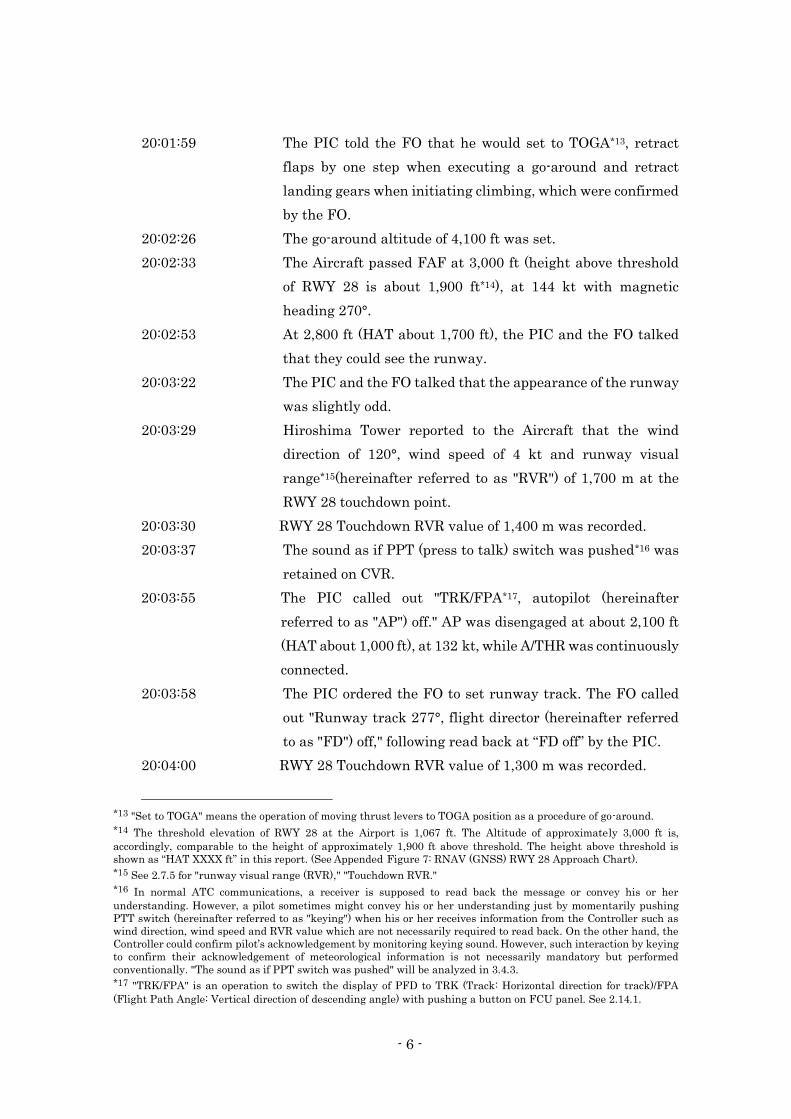
20:01:59 The PIC told the FO that he would set to TOGA*13, retract
flaps by one step when executing a go-around and retract
landing gears when initiating climbing, which were confirmed
by the FO.
20:02:26 The go-around altitude of 4,100 ft was set.
20:02:33 The Aircraft passed FAF at 3,000 ft (height above threshold
of RWY 28 is about 1,900 ft*14), at 144 kt with magnetic
heading 270°.
20:02:53 At 2,800 ft (HAT about 1,700 ft), the PIC and the FO talked
that they could see the runway.
20:03:22 The PIC and the FO talked that the appearance of the runway
was slightly odd.
20:03:29 Hiroshima Tower reported to the Aircraft that the wind
direction of 120°, wind speed of 4 kt and runway visual
range*15(hereinafter referred to as "RVR") of 1,700 m at the
RWY 28 touchdown point.
20:03:30 RWY 28 Touchdown RVR value of 1,400 m was recorded.
20:03:37 The sound as if PPT (press to talk) switch was pushed*16 was
retained on CVR.
20:03:55 The PIC called out "TRK/FPA*17, autopilot (hereinafter
referred to as "AP") off." AP was disengaged at about 2,100 ft
(HAT about 1,000 ft), at 132 kt, while A/THR was continuously
connected.
20:03:58 The PIC ordered the FO to set runway track. The FO called
out "Runway track 277°, flight director (hereinafter referred
to as "FD") off," following read back at “FD off” by the PIC.
20:04:00 RWY 28 Touchdown RVR value of 1,300 m was recorded.
*13 "Set to TOGA" means the operation of moving thrust levers to TOGA position as a procedure of go-around.
*14 The threshold elevation of RWY 28 at the Airport is 1,067 ft. The Altitude of approximately 3,000 ft is,
accordingly, comparable to the height of approximately 1,900 ft above threshold. The height above threshold is
shown as “HAT XXXX ft” in this report. (See Appended Figure 7: RNAV (GNSS) RWY 28 Approach Chart).
*15 See 2.7.5 for "runway visual range (RVR)," "Touchdown RVR."
*16 In normal ATC communications, a receiver is supposed to read back the message or convey his or her
understanding. However, a pilot sometimes might convey his or her understanding just by momentarily pushing
PTT switch (hereinafter referred to as "keying") when his or her receives information from the Controller such as
wind direction, wind speed and RVR value which are not necessarily required to read back. On the other hand, the
Controller could confirm pilot’s acknowledgement by monitoring keying sound. However, such interaction by keying
to confirm their acknowledgement of meteorological information is not necessarily mandatory but performed
conventionally. "The sound as if PPT switch was pushed" will be analyzed in 3.4.3. *17 "TRK/FPA" is an operation to switch the display of PFD to TRK (Track: Horizontal direction for track)/FPA
(Flight Path Angle: Vertical direction of descending angle) with pushing a button on FCU panel. See 2.14.1.
- 7 -
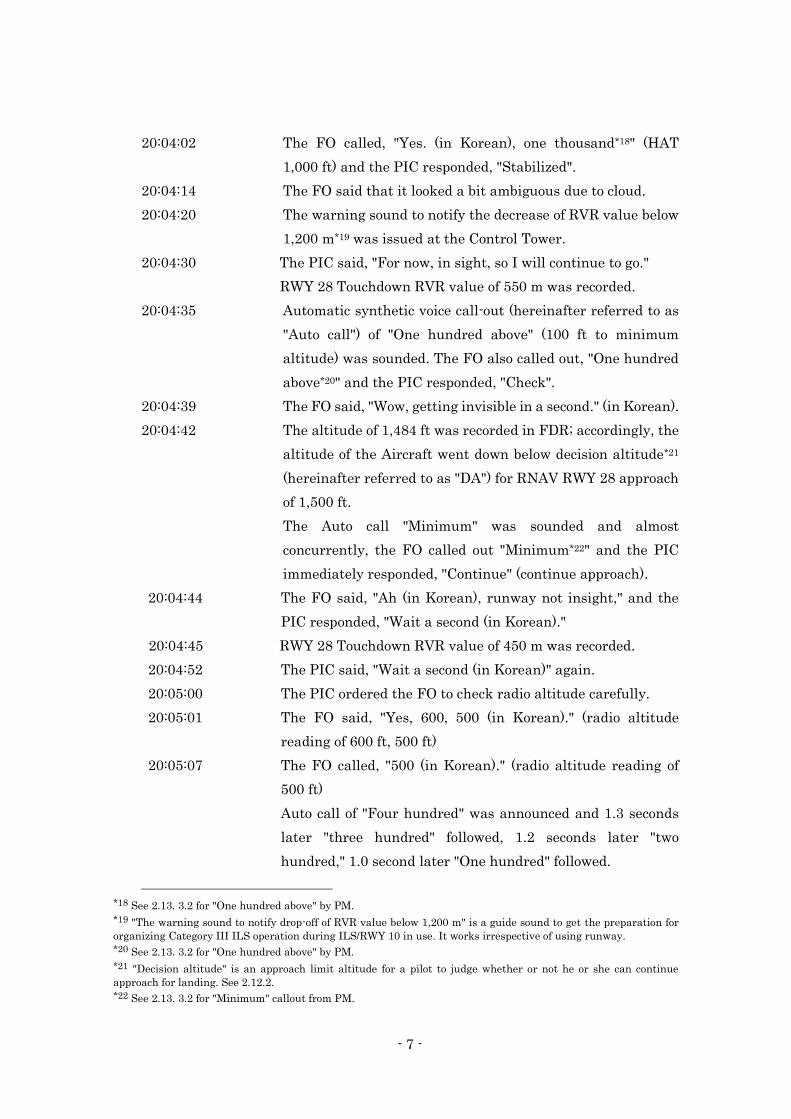
20:04:02 The FO called, "Yes. (in Korean), one thousand*18" (HAT
1,000 ft) and the PIC responded, "Stabilized".
20:04:14 The FO said that it looked a bit ambiguous due to cloud.
20:04:20 The warning sound to notify the decrease of RVR value below
1,200 m*19 was issued at the Control Tower.
20:04:30 The PIC said, "For now, in sight, so I will continue to go."
RWY 28 Touchdown RVR value of 550 m was recorded.
20:04:35 Automatic synthetic voice call-out (hereinafter referred to as
"Auto call") of "One hundred above" (100 ft to minimum
altitude) was sounded. The FO also called out, "One hundred
above*20" and the PIC responded, "Check".
20:04:39 The FO said, "Wow, getting invisible in a second." (in Korean).
20:04:42 The altitude of 1,484 ft was recorded in FDR; accordingly, the
altitude of the Aircraft went down below decision altitude*21
(hereinafter referred to as "DA") for RNAV RWY 28 approach
of 1,500 ft.
The Auto call "Minimum" was sounded and almost
concurrently, the FO called out "Minimum*22" and the PIC
immediately responded, "Continue" (continue approach).
20:04:44 The FO said, "Ah (in Korean), runway not insight," and the
PIC responded, "Wait a second (in Korean)."
20:04:45 RWY 28 Touchdown RVR value of 450 m was recorded.
20:04:52 The PIC said, "Wait a second (in Korean)" again.
20:05:00 The PIC ordered the FO to check radio altitude carefully.
20:05:01 The FO said, "Yes, 600, 500 (in Korean)." (radio altitude
reading of 600 ft, 500 ft)
20:05:07 The FO called, "500 (in Korean)." (radio altitude reading of
500 ft)
Auto call of "Four hundred" was announced and 1.3 seconds
later "three hundred" followed, 1.2 seconds later "two
hundred," 1.0 second later "One hundred" followed.
*18 See 2.13. 3.2 for "One hundred above" by PM.
*19 "The warning sound to notify drop-off of RVR value below 1,200 m" is a guide sound to get the preparation for
organizing Category III ILS operation during ILS/RWY 10 in use. It works irrespective of using runway.
*20 See 2.13. 3.2 for "One hundred above" by PM.
*21 "Decision altitude" is an approach limit altitude for a pilot to judge whether or not he or she can continue
approach for landing. See 2.12.2.
*22 See 2.13. 3.2 for "Minimum" callout from PM.
- 8 -
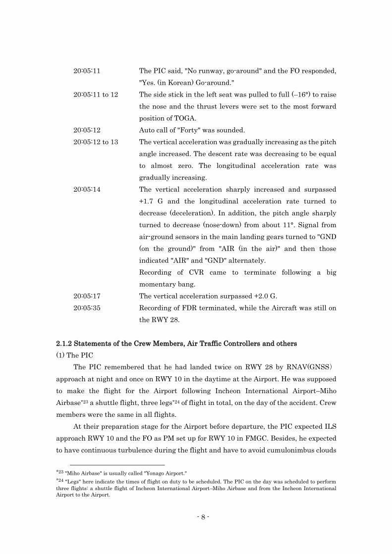
20:05:11 The PIC said, "No runway, go-around" and the FO responded,
"Yes. (in Korean) Go-around."
20:05:11 to 12 The side stick in the left seat was pulled to full (–16°) to raise
the nose and the thrust levers were set to the most forward
position of TOGA.
20:05:12 Auto call of "Forty" was sounded.
20:05:12 to 13 The vertical acceleration was gradually increasing as the pitch
angle increased. The descent rate was decreasing to be equal
to almost zero. The longitudinal acceleration rate was
gradually increasing.
20:05:14 The vertical acceleration sharply increased and surpassed
+1.7 G and the longitudinal acceleration rate turned to
decrease (deceleration). In addition, the pitch angle sharply
turned to decrease (nose-down) from about 11°. Signal from
air-ground sensors in the main landing gears turned to "GND
(on the ground)" from "AIR (in the air)" and then those
indicated "AIR" and "GND" alternately.
Recording of CVR came to terminate following a big
momentary bang.
20:05:17 The vertical acceleration surpassed +2.0 G.
20:05:35 Recording of FDR terminated, while the Aircraft was still on
the RWY 28.
2.1.2 Statements of the Crew Members, Air Traffic Controllers and others
(1) The PIC
The PIC remembered that he had landed twice on RWY 28 by RNAV(GNSS)
approach at night and once on RWY 10 in the daytime at the Airport. He was supposed
to make the flight for the Airport following Incheon International Airport–Miho
Airbase*23 a shuttle flight, three legs*24 of flight in total, on the day of the accident. Crew
members were the same in all flights.
At their preparation stage for the Airport before departure, the PIC expected ILS
approach RWY 10 and the FO as PM set up for RWY 10 in FMGC. Besides, he expected
to have continuous turbulence during the flight and have to avoid cumulonimbus clouds
*23 "Miho Airbase" is usually called "Yonago Airport."
*24 "Legs" here indicate the times of flight on duty to be scheduled. The PIC on the day was scheduled to perform
three flights: a shuttle flight of Incheon International Airport–Miho Airbase and from the Incheon International
Airport to the Airport.
- 9 -
during the approach, and shared the expectation with flight attendants (hereinafter
referred to as "FAs"). He, as always, asked for the FO to proactively give advices without
hesitation about anything anytime when he noticed, while trying to create a good
atmosphere in a cockpit where the FO felt free to speak out.
The PIC and the FO confirmed with each other such characteristics of the Airport
that it is located in the mountainous area; therefore, only its light is visible in a pitch-
dark at night, there is a slope on the runway and its both ends have cliffs, and the
approach light system of RWY 28 is short.
As the PIC could not get ATIS information about the Airport during cruise, he
provisionally performed an approach briefing for RWY 10 ILS approach which was
already set. He came to know RNAV RWY 28 approach in use by receiving ATIS
information during descent, in which the meteorological conditions were not reported in
a bad way.
During approach, the PIC flew the Aircraft toward VISTA and began a final
approach while avoiding the scattered cumulonimbus areas with AP and A/THR
engaged. The Aircraft was cleared for landing with information about light wind
following transferred to Hiroshima Tower. In conformity with the POM, the PIC had
completed Landing checklist before beginning a final approach and the FO called out in
a proper manner. The PIC disengaged AP because the runway was clearly in sight at
about HAT 1,200 ft. At about HAT 800 ft, although it became slightly difficult to see the
runway since it has been covered with fog, he continued approach referring to
instruments as well and gradually he could see PAPI*25. In the course of the approach,
PAPI often became difficult to see; however, when the FO called out, "One hundred
above" and "Minimum", the PIC responded, "Continue", because he could continuously
see the runway. Subsequently, he had never lost the sight of the runway and continued
approach occasionally referring to the instruments. Then, the PIC asked the FO to read
out the RA (radio altitude) at the final stage of the approach.
The PIC was never conscious of flying lower in the approach; however, he decided
to execute a go-around because he noticed an instrument indicating the deviation to the
right of the course. He pulled the side-stick hard to have the Aircraft pitch up and
increased the power. He does not know if the thrust levers were completely set to TOGA
position at the moment and does not remember if he checked the TOGA display on
FMA*26.
*25 "PAPI": precision approach path indicator is the indication of "white: 2 and red: 2 (On Glide Path)" shows that
the position of an aircraft is on the approach path of the standard 3°, "white: 1 and red: 3 (Slightly Low)" on the
slightly low approach path and "red 4 (Low)" on low approach path.
*26 "FMA" is an annunciator that displays modes for horizontal and vertical directions of AP/FD.
- 10 -
As the Aircraft was beginning to pitch up, in the next moment, the fuselage tail hit
something and contacted with the ground. Then, it went into the runway and bounded
about three times. The PIC applied the maximum brake to stop it and tried to maintain
the direction of the runway; however, it veered off to the left (south side) of the runway
and stopped in the grass area with turning the nose.
The PIC ordered the FO to perform EMERGENCY EVACUATION Checklist*27.
During proceeding the checklist, the purser came into the cockpit. He ordered her to be
out and wait for an instruction because he gave priority to performing the checklist. He
tried to notify Hiroshima Tower which is one of the checklist items; however, he could
not successfully communicate with him due to bad communication conditions, though he
remembered that he could hear the response from Hiroshima Tower at the beginning.
He realized that the FAs had already set to evacuate as well as the passengers because
he could monitor the situation in the cabin while in the cockpit. He evacuated with an
evacuation slide following completion of the checklist.
The passengers and FAs seemed to have already started walking toward the
terminal. Although the firefighters had arrived near the site, neither they seemed to
work actively nor gave instructions to the PIC.
While flying with AP, usually, the PIC used to disengaging AP and changing to
manual flying when he could see the runway in a good weather, even if above HAT 1,000
ft.
When the accident occurred, the PIC was monitoring PAPI and instruments in the
ratio of three to seven while flying below DA with visual maneuvering for landing. In
addition, he asked the FO to read out of RA; however, it was not because he counted on
RA and was going to use it to continue approach but because he intended to use it as a
supplementary measure to comprehend the general picture of descent. In hindsight, the
PIC thought that it was meaningless.
The PIC thought that he could have made a little more careful approach if he had
received the information about the weather worsening. He remembers that he was not
informed of RVR value but only informed of wind information when the Aircraft was
cleared for landing. He could not anticipate the meteorological conditions might
deteriorate.
In the Company, pilots shall use the approach chart based on officially notified
AIP*28 and the PIC thought that his own weather minima applied to the RNAV RWY 28
*27 See 2.15.2 for "EMERGENCY EVACUATION Checklist." *28 "Approach chart based on officially notified AIP" conform to Appended Figure 7: RNAV (GNSS) RWY 28
Approach Chart. See 2.12.4.
- 11 -
approach was the minima of RVR 1,400 m described in the approach charts. He
presumed that he would have executed a go-around if he had been informed of RVR value
below the weather minima during the final approach.
(2) The FO
It was the first time for the FO to fly with the PIC. The PIC flew the outward flight
to Miho Airbase as PF in the shuttle flight between Incheon International Airport and
Miho Airbase and the FO flew the returning flight as PF. Then, the PIC flew the flight
to the Airport as PF. As bumpy air conditions were presented in every flight, the FO had
some fatigue.
The FO had landed once on the Airport by ILS RWY 10 at night and it was the first
time for him to land on RWY 28. The whole view around the Airport was completely
dark; however, he could clearly see the lightings of the Airport after passing 3,000 ft.
The Aircraft was cleared landing and the Landing checklist was completed during the
final approach. The PIC disengaged AP at approximately HAT 1,000 ft and switched to
manual operation. He set FD off and switched to TRK/FPA mode, and then confirmed
“Bird*29 ” displayed on PFD. After that, the visibility was getting worsened and it was
getting difficult to see the runway. Although he was monitoring instrument such as
runway track and descent rate, he does not remember if the Aircraft was flying along an
appropriate approach path angle with checking indication of PAPI or V/DEV*30 of PFD.
The FO could see the runway when calling "One hundred above." Although he does
not remember for sure if he could see it when calling, "Minimum" and the PIC responded,
"Continue". Therefore, as he lost sight of it, he said, "I could not see the runway;"
however, he thinks there was no reaction from the PIC. He was suddenly asked by the
PIC to watch RA, and then he began reading out RA value because he, at that time,
thought the bad meteorological conditions led the PIC to do so. After that, when the PIC
declared go-around and was about to commence the procedure, the FO saw some kinds
of lights and the Aircraft collided with something.
Looking back, the FO should have asserted a go-around immediately after he lost
sight of the runway; moreover, considering the topographic aspect around the Airport, it
was wrong to read out RA.
The FO felt a kind of deceleration when the Aircraft was in a landing roll on the
runway, and the Aircraft veered off the runway and came to a stop. The PIC made an
*29 "Bird" is displayed when TRK/FPA is selected. See 2.14.2.
*30 "V/DEV" is an indicator that shows deviation amount from standard descent path during RNAV approach. See
2.12.6(2).
- 12 -
urgent call of MAYDAY*31 to Hiroshima Tower. When they completed EMERGENCY
EVACUATION Checklist and stepped out from the cockpit, he found that the passengers
and FAs had already evacuated from the Aircraft. He evacuated as well with an
evacuation slide.
(3) Hiroshima Tower
Hiroshima Tower was on duty from the afternoon on that day. The meteorological
conditions around the Airport was not so bad, though clouds area from the south were
intermittently covering up. Hiroshima Tower established communication with the
Aircraft at around 10 nm final and issued landing clearance with information on wind
direction and wind speed.
When the Aircraft approached approximately three to four nm on the final
approach, meteorological conditions suddenly got deteriorated and the RVR value was
decreased; therefore, he informed the Aircraft of the RVR value as well as wind direction
and speed by one-way transmission. Afterwards, he monitored RVR values decreased
further. As the Aircraft was just close to land, Hiroshima Tower assumed that the pilot
would spontaneously execute a go-around if he could not see the runway; besides, the
possibility was high. Thus Hiroshima Tower was thinking of the procedures to be taken,
including handling of departure aircraft, prepared for the case that the Aircraft executed
a go-around.
Hiroshima Tower was continuing to carefully watch outside such as the direction
in which the Aircraft approached. When he saw it emerging from the fog bank and
running on the runway with sparks as if scraping, he asked the Flight Data Position
Controller to activate crash phone*32.
(4) The Flight Data Position Controller
Based on the TAF*33 information, the Flight Data Position Controller assumed that
the weather was not clear. He thought that there was possibility to change runway to
RWY 10 from RWY 28 which was in use, depending on wind and visibility. As he received
a report from the pilot, landed 10 minutes before the arrival of the Aircraft, that runway
was in sight around altitude of 2,000 ft; therefore, he was carefully watching the final
approach of the Aircraft. It was getting foggy slightly and Hiroshima Tower informed
the Aircraft of RVR value of 1,700 m.
*31 MAYDAY is a distress traffic from a pilot starting previously with MAYDAY, MAYDAY, MAYDAY.
*32 "Crash phone" is a mean of contact to inform promptly the command desk in the fire department building of the
Office and aeronautical information officer of emergency inside/vicinity of the airport from the control tower.
*33 "TAF" stands for Terminal Aerodrome Forecast.
- 13 -
The Flight Data Position Controller could not exactly see how the Aircraft was
landing; however, he heard big bang twice. He promptly pushed the button of a crash
phone and called airport rescue and firefighting service for dispatch because he saw
sparks around the touchdown zone area.
(5) Purser
The purser took a seat backwards in the forward of the cabin.
The Aircraft had been continuously shaking by turbulence; however, it was getting
settled around when it initiated a final approach for the Airport. Just when she was
expecting to land soon, there was a sudden big impact and the Aircraft landed
abnormally. The purser shouted continuously "Heads down, hold your uncles," in a loud
voice.
After the Aircraft stopped, the purser found the cockpit door open and asked the
PIC if the Aircraft was all right. She was instructed to close the door and wait outside.
After that, she heard FAs in the rear of the cabin tense call, "Manager*34, Manager," and
it seemed that smoke was coming up in the rear. She decided that emergency evacuation
was required, and then opened L1 door in the front left. Having confirmed the inflation
of the evacuation slide, she instructed the passengers to evacuate.
Although the purser thought that she could announce emergency evacuation by PA
(passenger address system), she did not know whether it actually worked or not. Having
confirmed the completion of all passengers’ evacuation, she told the PIC that the FAs
would evacuate immediately as well. On the ground, she instructed the passengers to
step away from the Aircraft. She could see the boarding mechanic evacuating; however,
she saw neither the PIC nor the FO there. After evacuation, she saw three fire engines
around L1 and L2 side; however, neither instructions nor supports were provided.
(6) Other FAs
While the Aircraft was landing roll after a big impact, FAs saw oxygen masks
dropping from the ceiling. As it became dark in the cabin, FAs were continuously
shouting at passengers to brace for impact. After the Aircraft stopped, they could not
talk with the purser with the interphone. They thought that emergency evacuation was
necessary because something like smoke seemed to come up. They think that the
emergency evacuation signal did not sound. An FA in the middle section of the cabin
asked the passengers to open the emergency exit in the middle left cabin and deploy the
slide. On the ground after evacuation, they noticed the passengers remained staying
*34 "Manager" is the same meaning of purser.
- 14 -
near the evacuation slides. As they were afraid that the Aircraft might explode by some
chance, they instructed them to step away from it using a megaphone, then they walked
towards the terminal. No fire engines were coming close to the Aircraft and fire fighters
did not provide them with any instructions such as an evacuation guidance.
(7) Boarding mechanic
Boarding mechanic was seated at 27 F in the right rear of the cabin. He experienced
a big impact at landing and saw the fire breaking out from the left engine. Smoke was
coming up in the cabin and something odd smelled. FAs continuously shouted for bracing
for impact. The Aircraft suddenly veered and stopped. When he raised his head, the
inside of the cabin was dark; however, the emergency lights and such in the cabin were
illuminated. FAs in the rear cabin tried to call for Manager and loudly spoke out that
the interphone system did not work. No fire broke out and the smoke was gradually
getting better.
He helped FAs carry out emergency evacuation procedures. They were checking no
passengers left in the cabin. After that, they evacuated with slides and he followed them.
Two flight crew members seemed to remain in the cockpit and he did not see them
outside of the Aircraft immediately after evacuation. It was raining outside and the grass
areas were muddy. Fire fighters were preparing for firefighting activities with sirens of
fire engines sounding.
(8) Passengers
Passengers felt bigger impact than usual at landing. The doors of the overhead
storage bins were open and the baggage dropped out from them, and the oxygen masks
fell from the ceiling. FAs were shouting to lower the heads to the passengers. It seemed
to have fire come out from both left and right of the engines and smoke intruded into the
cabin; however, the situation was not so bad. As the cabin was not completely dark, they
could manage to see things to some extent.
They were informed of emergency situation in various languages such as English,
Korean, and Japanese, and they were instructed to evacuate after the Aircraft stopped.
On the ground, they saw FAs guiding passengers with gestures, announcement through
megaphone and with flashlights. In addition, an FA announced in Japanese through
megaphone to step away from the Aircraft immediately and they left for the terminal
voluntarily. There were fire engines coming nearby; however, no guidance was provided
by firefighters.
- 15 -
(9) Information from departure aircraft
There was a scheduled flight aircraft being preparing for departure at the Airport
when the Aircraft was arriving. When the aircraft was about to leave the apron following
fully prepared for departure, the flight crew members heard Hiroshima Tower notifying
the Aircraft of the RVR value. The visibility, when the departure aircraft was moving on
the taxiway for RWY 28 for take-off, was not so bad. When it was approaching to RWY
28, they saw a vague orange light in the distance from the threshold of RWY 28.
The flight crew members saw the sparks while the Aircraft was in the landing roll.
Afterwards, during they were holding on the taxiway, suddenly a fogbank emerged onto
the runway in a minute or two.
The accident occurred at the point of 325 m east of the threshold of RWY 28 at the
Airport (34° 26' 10" N, 132° 56' 21" E) , at the time of 20:05, on April 14, 2015.
(See Appended Figure 1: Estimated Flight Route, Appended Figure 2: Estimated
Descent Path, Appended Figure 3: FDR Records, Appended Figure 4: Situation of
Collision and the Parts Damaged, Appended Figure 5 Track and Traces on the Runway,
Appended Figure 7: RNAV(GNSS) RWY 28 Approach Procedure, Appended Figure 8:
Meteorological Conditions, Photo 1: The Aircraft, Photo 2: The Parts Damaged of the
Aircraft, Photo 3-1: The Site of the Accident (1), Photo 3-2: The Site of the Accident (2),
Photo 4: The Vicinity of the Aircraft Stop Position, Attachment 1: ATC Communication
Records, Attachment 2-1, 2-2: CVR Records)
2.2 Injuries to Persons
Among 81 people on board, 28 persons in total were slightly injured, consisting of
26 passengers and two FAs.
2.3 Damage to the Aircraft
2.3.1 Extent of Damage
The Aircraft was substantially damaged.
2.3.2 Damages to the Aircraft Components
Fuselage: Lower surface, Side surface and Tail:
Broken extensively from around the center portion to the tail
Wing: Flaps: Broken, partly fractured in right flap
Left wing tip: Damaged
Main landing gears: Both landing gears: Damaged
- 16 -
Gear well door and gear lock stay of
the left main landing gear: Broken
Engines: Both engines and LH pylon: Significantly Damaged
Both engine cowls: Damaged
Horizontal stabilizers: Left horizontal stabilizer: Fractured from around the center
(external part detached from the Aircraft)
: Right horizontal stabilizer: Damaged in leading edge
(See Appended Figure 4: Situation of Collision and the Parts Damaged, Photo 1:
The Aircraft, Photo 2: The Parts Damaged of the Aircraft)
2.4 Information Relevant to Damaged Properties other than the Aircraft
Aeronautical Radio Navigation Aids:
Frame stand of localizer antenna (hereinafter referred to as "the LOC frame stand")
Destroyed
Aerodrome beacon:
Light of SALS (15) and their poles Damaged
Lights of wide-angle ALS (two) and their poles Damaged
Runway edge light, runway centerline light and overrun area edge light
Damaged
Surface of runway: Scratch marks at a plurality of locations
(See Figure 3: Aerodrome Lightings at RWY 28 side, Figure 6: Traces in front of
RWY 28 Threshold, Appended Figure 4: Situation of Collision and the Parts
Damaged, Appended Figure 5: Track and Traces on the Runway)
2.5 Personnel Information
2.5.1 Flight Crew Members
(1) PIC: Male, Age 47
Airline Transport pilot certificate (Airplane) May 19, 2010
Type rating for Airbus A320 March 6, 2013
Class 1 aviation medical certificate
Validity November 30, 2015
Total flight time 8,242 hr and 38 min
Flight time in the last 30 days 65 hr and 47 min
Total flight time on the type of the aircraft 1,318 hr and 38 min
Flight time in the last 30 days 65 hr and 47 min
- 17 -
(2) FO: Male, Age 35
Commercial pilot certificate (Airplane) December 5, 2011
Type rating for Airbus A320 April 1, 2013
Instrument flight certificate October 6, 2011
Class 1 aviation medical certificate
Validity November 30, 2015
Total flight time 1,588 hr and 00 min
Flight time in the last 30 days 59 hr and 49 min
Total flight time on the type of the aircraft 1,298 hr and 00 min
Flight time in the last 30 days 59 hr and 49 min
2.5.2 Air Traffic Controllers
(1) Hiroshima Tower: Male, age 45
Air traffic control certificate
Ground control approach service June 1, 1998
Medical certificate
Validity June 29, 2016
Aviation English Language Proficiency Certificate
Validity March 31, 2018
(2) The Flight Data Position Controller: Male, age 59
Air traffic control certificate
Ground control approach service April 1, 1977
Medical certificate
Validity June 30, 2016
Aviation English Language Proficiency Certificate
Validity March 31, 2018
2.6 Information Relevant to the Aircraft
2.6.1 Aircraft
Type Airbus A320-200
Serial number 3244
Date of manufacture August 30, 2007
Certificate of airworthiness AB07024
Validity Since September 25, 2012 until discontinued/limited
Category of airworthiness Aircraft Transport T
- 18 -
Total flight time 23,595 hr 17 min
Flight time since Inspection C performed on October 14, 2014 1,263 hr 55 min
(See Appended Figure 6: Three-view drawing of Airbus A320-200)
2.6.2 Weight and Balance
When the accident occurred, the weight of Aircraft is estimated to have been
125,000 lb, and the position of the center of gravity is estimated to have been 33.3% mean
aerodynamic chord (MAC)*35; accordingly, both of which are estimated to have been
within the allowable ranges (the maximum landing weight of 142,198 lb and the center
of gravity range of 18.2 to 40.7% MAC corresponding to the weight at the time of the
accident).
2.7 Meteorological Information
2.7.1 Meteorological Summary
At 16:00 on the day of the accident, the Kansai Aviation Weather Service Center
announced meteorological summary as follows (excerpts):
(1) Meteorological summary of Kinki, Chugoku and Shikoku area
Through tomorrow: April 15, middle and upper cloud might spread and it would be
rainy in some areas in consequence of trough and cold air mass in the air. Besides,
convective clouds would be developing and thunder might be generated in some areas
because the state of the air becomes unstable. (omitted)
(2) Comments on Hiroshima Airport
From early tonight through early tomorrow morning, convective clouds would be
developing, thunder might be generated, and VIS (visibility) would be getting worse and
the airport would become IMC*36 due to rain or BR (mist). (omitted)
(See Appended Figure 8: Meteorological Conditions)
2.7.2 Observation Value of TAF and Aviation Weather at the Airport
(1) Terminal Aerodrome Forecast (TAF)
TAF at the Airport announced at 14:00 on the day of the accident was as follows:
15:00 to 21:00 on the following day:
*35 "MAC" stands for Mean Aerodynamic Chord, which is a blade chord representing aerodynamic characteristic of
a blade. MAC is the typical chord length when they are not identical, such as those of a sweptwing. The value 28.3%
MAC indicates the position at 28.3% from the leading edge of the aerodynamic average of blade chords.
*36 When meteorological condition at airport becomes ground visibility below 5,000 m, or ceiling below 1,000 ft, the
airport is "IMC" (instrument meteorological condition).
- 19 -
Wind direction: 220°, wind speed: 6 kt, prevailing visibility: 10 km or more
Rain shower
Cloud Amount: FEW*37, height of cloud ceiling: 2,000 ft
Amount: BKN*38, height of cloud ceiling: 4,500 ft
Temporary changes occurred during 19:00 to 22:00:
Prevailing visibility: 4,000 m, light thunderstorm, mist
Cloud Amount: FEW, height of cloud ceiling: 1,500 ft
Amount: FEW, height of cloud ceiling: 2,500 ft, cumulonimbus
Amount: SCT*39, height of cloud ceiling: 3,000 ft
Amount: BKN, height of cloud ceiling: 4,000 ft
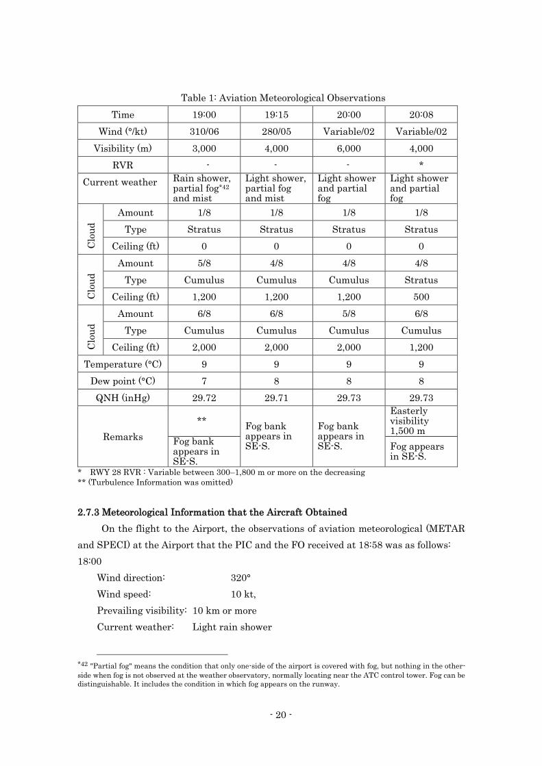
(2) Aviation Meteorological Observations
Aviation Meteorological Observatory Values (METAR*40 and SPECI*41) at the
Airport from 19:00 to the time immediately after the accident on the day of the accident
were as follows:
(The time of the accident occurred was 20:05)
*37 "FEW" indicates clouds amount of 1/8 to 2/8.
*38 "BKN" indicates clouds amount of 5/8 to 7/8.
*39 "SCT" indicates clouds amount of 3/8 to 4/8.
*40 "METAR" means “Aviation Routine Weather Report.”
*41 "SPECI" means “Aviation Special Weather Report.”
- 20 -
Table 1: Aviation Meteorological Observations
Time 19:00 19:15 20:00 20:08
Wind (°/kt) 310/06 280/05 Variable/02 Variable/02
Visibility (m) 3,000 4,000 6,000 4,000
RVR - - - *
Current weather Rain shower, partial fog*42 and mist
Light shower, partial fog and mist
Light shower and partial fog
Light shower and partial fog
Clo
ud
Amount 1/8 1/8 1/8 1/8
Type Stratus Stratus Stratus Stratus
Ceiling (ft) 0 0 0 0
Clo
ud
Amount 5/8 4/8 4/8 4/8
Type Cumulus Cumulus Cumulus Stratus
Ceiling (ft) 1,200 1,200 1,200 500
Clo
ud
Amount 6/8 6/8 5/8 6/8
Type Cumulus Cumulus Cumulus Cumulus
Ceiling (ft) 2,000 2,000 2,000 1,200
Temperature (°C) 9 9 9 9
Dew point (°C) 7 8 8 8
QNH (inHg) 29.72 29.71 29.73 29.73
Remarks
**
Fog bank appears in SE-S.
Fog bank appears in SE-S.
Easterly visibility 1,500 m
Fog bank appears in SE-S.
Fog appears in SE-S.
* RWY 28 RVR : Variable between 300–1,800 m or more on the decreasing
** (Turbulence Information was omitted)
2.7.3 Meteorological Information that the Aircraft Obtained
On the flight to the Airport, the observations of aviation meteorological (METAR
and SPECI) at the Airport that the PIC and the FO received at 18:58 was as follows:
18:00
Wind direction: 320°
Wind speed: 10 kt,
Prevailing visibility: 10 km or more
Current weather: Light rain shower
*42 "Partial fog" means the condition that only one-side of the airport is covered with fog, but nothing in the other-
side when fog is not observed at the weather observatory, normally locating near the ATC control tower. Fog can be
distinguishable. It includes the condition in which fog appears on the runway.
- 21 -
Cloud: Amount: FEW, Type: Cumulus, Cloud base: 1,500 ft
Amount: BKN, Type: Cumulus, Cloud base: 2,000 ft,
Amount: BKN, cloud type: Stratocumulus, height of cloud ceiling: 5,000 ft
Temperature: 10°C
Dew-point: 6°C
QNH: 29.69 inHg
18:23
Wind direction: Variable
Wind speed: 2 kt
Prevailing visibility: 4,000 m
Current weather: Rain shower, mist
Cloud: Amount: FEW, Type: Stratus, Cloud base: 200 ft
Amount: BKN, Type: Cumulus, Cloud base: 1,200 ft
Amount: BKN, Type: Cumulus, Cloud base: 2,000 ft
Temperature: 9°C
Dew-point: 7°C
QNH: 29.71 inHg
In addition, ATIS information "T" at the Airport which the PIC and the FO received
during descent showed RWY 28 was in use, and included the same content as the
aviation meteorological observatory at 19:15 described in 2.7.2(2). However, there were
no descriptions of the remarks: "Fogbank in southeast to south," in the memo which was
left in the cockpit.
According to the CVR records, although there were some noises, reception condition
was not so bad to monitor the ATIS information.
2.7.4 Wind Data Before the Accident Occurred
Data*43 of wind direction (magnetic direction) and wind speed (the two-minute
average value of the value observed by three-second intervals) observed for 40 minutes
around the time when the accident occurred is shown in Table 2.
*43 Anemometers are located at two places in the vicinity of RWY 10 and RWY 28 touchdown points at the Airport.
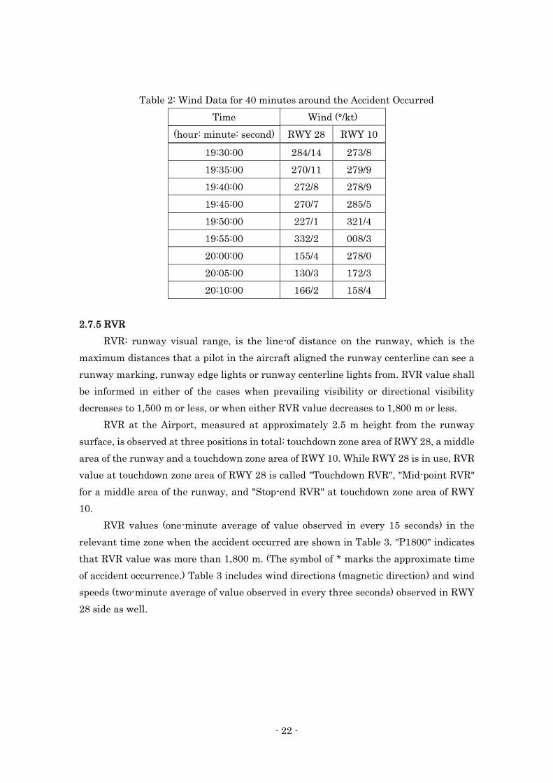
- 22 -
Table 2: Wind Data for 40 minutes around the Accident Occurred
Time Wind (°/kt)
(hour: minute: second) RWY 28 RWY 10
19:30:00 284/14 273/8
19:35:00 270/11 279/9
19:40:00 272/8 278/9
19:45:00 270/7 285/5
19:50:00 227/1 321/4
19:55:00 332/2 008/3
20:00:00 155/4 278/0
20:05:00 130/3 172/3
20:10:00 166/2 158/4
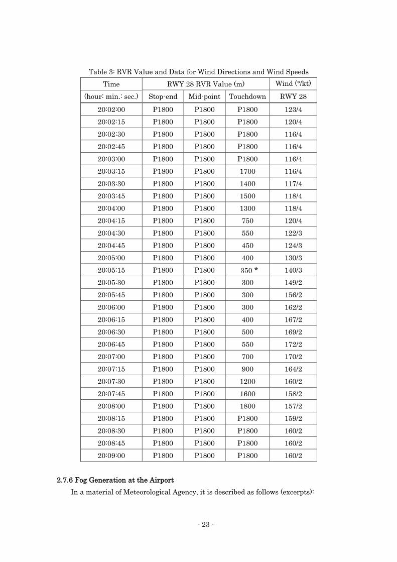
2.7.5 RVR
RVR: runway visual range, is the line-of distance on the runway, which is the
maximum distances that a pilot in the aircraft aligned the runway centerline can see a
runway marking, runway edge lights or runway centerline lights from. RVR value shall
be informed in either of the cases when prevailing visibility or directional visibility
decreases to 1,500 m or less, or when either RVR value decreases to 1,800 m or less.
RVR at the Airport, measured at approximately 2.5 m height from the runway
surface, is observed at three positions in total: touchdown zone area of RWY 28, a middle
area of the runway and a touchdown zone area of RWY 10. While RWY 28 is in use, RVR
value at touchdown zone area of RWY 28 is called "Touchdown RVR", "Mid-point RVR"
for a middle area of the runway, and "Stop-end RVR" at touchdown zone area of RWY
10.
RVR values (one-minute average of value observed in every 15 seconds) in the
relevant time zone when the accident occurred are shown in Table 3. "P1800" indicates
that RVR value was more than 1,800 m. (The symbol of * marks the approximate time
of accident occurrence.) Table 3 includes wind directions (magnetic direction) and wind
speeds (two-minute average of value observed in every three seconds) observed in RWY
28 side as well.
- 23 -
Table 3: RVR Value and Data for Wind Directions and Wind Speeds
Time RWY 28 RVR Value (m) Wind (°/kt)
(hour: min.: sec.) Stop-end Mid-point Touchdown RWY 28
20:02:00 P1800 P1800 P1800 123/4
20:02:15 P1800 P1800 P1800 120/4
20:02:30 P1800 P1800 P1800 116/4
20:02:45 P1800 P1800 P1800 116/4
20:03:00 P1800 P1800 P1800 116/4
20:03:15 P1800 P1800 1700 116/4
20:03:30 P1800 P1800 1400 117/4
20:03:45 P1800 P1800 1500 118/4
20:04:00 P1800 P1800 1300 118/4
20:04:15 P1800 P1800 750 120/4
20:04:30 P1800 P1800 550 122/3
20:04:45 P1800 P1800 450 124/3
20:05:00 P1800 P1800 400 130/3
20:05:15 P1800 P1800 350 * 140/3
20:05:30 P1800 P1800 300 149/2
20:05:45 P1800 P1800 300 156/2
20:06:00 P1800 P1800 300 162/2
20:06:15 P1800 P1800 400 167/2
20:06:30 P1800 P1800 500 169/2
20:06:45 P1800 P1800 550 172/2
20:07:00 P1800 P1800 700 170/2
20:07:15 P1800 P1800 900 164/2
20:07:30 P1800 P1800 1200 160/2
20:07:45 P1800 P1800 1600 158/2
20:08:00 P1800 P1800 1800 157/2
20:08:15 P1800 P1800 P1800 159/2
20:08:30 P1800 P1800 P1800 160/2
20:08:45 P1800 P1800 P1800 160/2
20:09:00 P1800 P1800 P1800 160/2
2.7.6 Fog Generation at the Airport
In a material of Meteorological Agency, it is described as follows (excerpts):
- 24 -
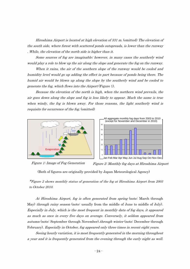
Hiroshima Airport is located at high elevation of 331 m. (omitted) The elevation of
the south side, where forest with scattered ponds outspreads, is lower than the runway
. While, the elevation of the north side is higher than it.
Some sources of fog are imaginable; however, in many cases the southerly wind
would play a role to blow up the air along the slope and generate the fog on the runway.
When it rains, the air of the southern slope of the runway would be cooled and
humidity level would go up adding the effect in part because of ponds being there. The
humid air would be blown up along the slope by the southerly wind and be cooled to
generate the fog, which flows into the Airport (Figure 1).
Because the elevation of the north is high, when the northern wind prevails, the
air goes down along the slope and fog is less likely to appear. Much the same is true
when windy, the fog is blown away. For those reasons, the light southerly wind is
requisite for occurrence of the fog. (omitted)
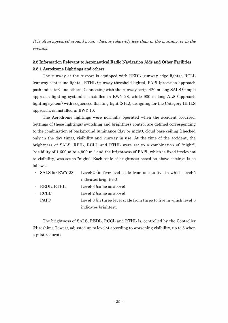
*Figure 2 shows monthly status of generation of the fog at Hiroshima Airport from 2003
to October 2010.
At Hiroshima Airport, fog is often generated from spring (note: March through
May) through rainy season (note: usually from the middle of June to middle of July).
Especially in July, which is the most frequent in monthly data of fog days, it appeared
as much as once in every five days on average. Conversely, it seldom appeared from
autumn (note: September through November).through winter (note: December through
February). Especially in October, fog appeared only three times in recent eight years.
Seeing hourly variation, it is most frequently generated in the morning throughout
a year and it is frequently generated from the evening through the early night as well.
All aggregate monthly fog days from 2003 to 2010 (except for November and December in 2010)
Evaporation
Figure 1: Image of Fog Generation Figure 2: Monthly fog days at Hiroshima Airport
Jan Feb Mar Apr May Jun Jul Aug Sep Oct Nov Dec
(Both of figures are originally provided by Japan Meteorological Agency)
- 25 -
It is often appeared around noon, which is relatively less than in the morning, or in the
evening.
2.8 Information Relevant to Aeronautical Radio Navigation Aids and Other Facilities
2.8.1 Aerodrome Lightings and others
The runway at the Airport is equipped with REDL (runway edge lights), RCLL
(runway centerline lights), RTHL (runway threshold lights), PAPI (precision approach
path indicator) and others. Connecting with the runway strip, 420 m long SALS (simple
approach lighting system) is installed in RWY 28, while 900 m long ALS (approach
lighting system) with sequenced flashing light (SFL), designing for the Category III ILS
approach, is installed in RWY 10.
The Aerodrome lightings were normally operated when the accident occurred.
Settings of these lightings: switching and brightness control are defined corresponding
to the combination of background luminance (day or night), cloud base ceiling (checked
only in the day time), visibility and runway in use. At the time of the accident, the
brightness of SALS, REIL, RCLL and RTHL were set to a combination of "night",
"visibility of 1,600 m to 4,900 m," and the brightness of PAPI, which is fixed irrelevant
to visibility, was set to "night". Each scale of brightness based on above settings is as
follows:
- SALS for RWY 28: Level-2 (in five-level scale from one to five in which level-5
indicates brightest)
- REDL, RTHL: Level-3 (same as above)
- RCLL: Level-2 (same as above)
- PAPI: Level-3 (in three-level scale from three to five in which level-5
indicates brightest.
The brightness of SALS, REDL, RCCL and RTHL is, controlled by the Controller
(Hiroshima Tower), adjusted up to level-4 according to worsening visibility, up to 5 when
a pilot requests.
- 26 -
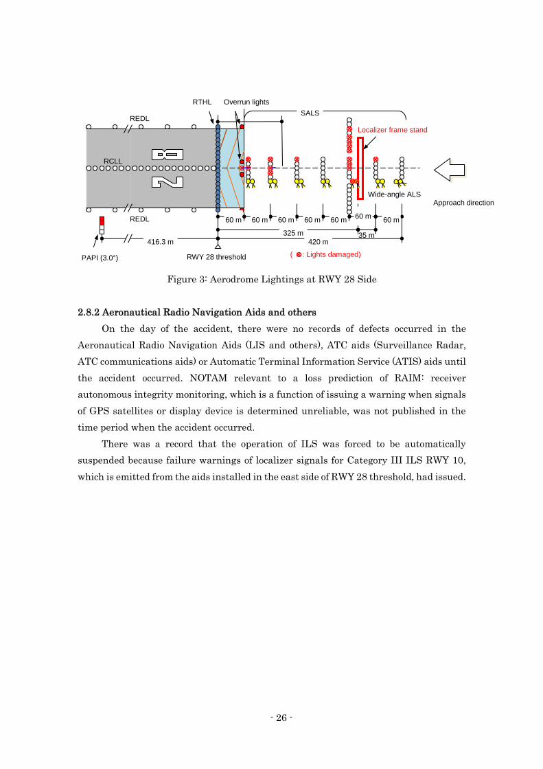
Figure 3: Aerodrome Lightings at RWY 28 Side
2.8.2 Aeronautical Radio Navigation Aids and others
On the day of the accident, there were no records of defects occurred in the
Aeronautical Radio Navigation Aids (LIS and others), ATC aids (Surveillance Radar,
ATC communications aids) or Automatic Terminal Information Service (ATIS) aids until
the accident occurred. NOTAM relevant to a loss prediction of RAIM: receiver
autonomous integrity monitoring, which is a function of issuing a warning when signals
of GPS satellites or display device is determined unreliable, was not published in the
time period when the accident occurred.
There was a record that the operation of ILS was forced to be automatically
suspended because failure warnings of localizer signals for Category III ILS RWY 10,
which is emitted from the aids installed in the east side of RWY 28 threshold, had issued.
35 m
60 m 60 m 60 m 60 m 60 m 60 m 325 m
416.3 m
RWY 28 threshold
RCLL
REDL
REDL
RTHL Overrun lights SALS
Wide-angle ALS
Localizer frame stand
( : Lights damaged) PAPI (3.0°)
420 m
60 m Approach direction
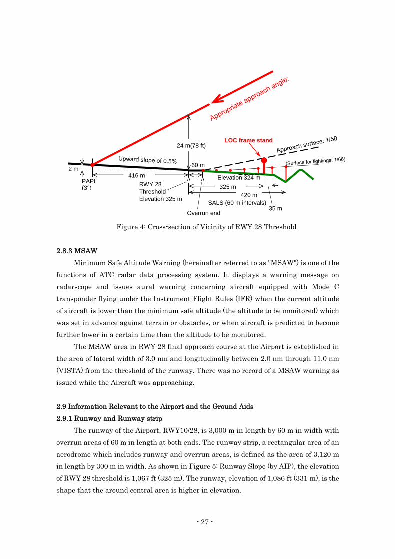
- 27 -
Figure 4: Cross-section of Vicinity of RWY 28 Threshold
2.8.3 MSAW
Minimum Safe Altitude Warning (hereinafter referred to as "MSAW") is one of the
functions of ATC radar data processing system. It displays a warning message on
radarscope and issues aural warning concerning aircraft equipped with Mode C
transponder flying under the Instrument Flight Rules (IFR) when the current altitude
of aircraft is lower than the minimum safe altitude (the altitude to be monitored) which
was set in advance against terrain or obstacles, or when aircraft is predicted to become
further lower in a certain time than the altitude to be monitored.
The MSAW area in RWY 28 final approach course at the Airport is established in
the area of lateral width of 3.0 nm and longitudinally between 2.0 nm through 11.0 nm
(VISTA) from the threshold of the runway. There was no record of a MSAW warning as
issued while the Aircraft was approaching.
2.9 Information Relevant to the Airport and the Ground Aids
2.9.1 Runway and Runway strip
The runway of the Airport, RWY10/28, is 3,000 m in length by 60 m in width with
overrun areas of 60 m in length at both ends. The runway strip, a rectangular area of an
aerodrome which includes runway and overrun areas, is defined as the area of 3,120 m
in length by 300 m in width. As shown in Figure 5: Runway Slope (by AIP), the elevation
of RWY 28 threshold is 1,067 ft (325 m). The runway, elevation of 1,086 ft (331 m), is the
shape that the around central area is higher in elevation.
PAPI (3°)
416 m
325 m
Overrun end
60 m
RWY 28
Threshold Elevation 325 m (1,067 ft)
420 m
2 m
24 m(78 ft)
Elevation 324 m
35 m SALS (60 m intervals)
LOC frame stand
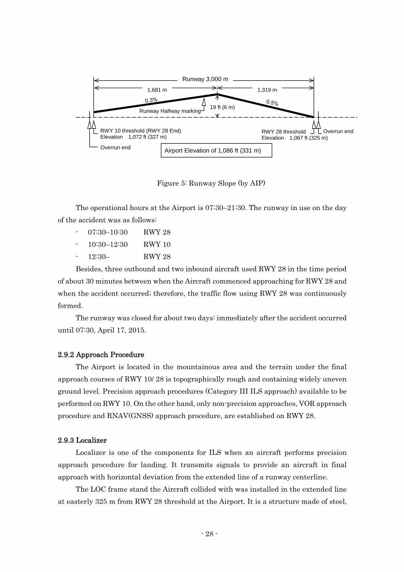
- 28 -
Figure 5: Runway Slope (by AIP)
The operational hours at the Airport is 07:30–21:30. The runway in use on the day
of the accident was as follows:
- 07:30–10:30 RWY 28
- 10:30–12:30 RWY 10
- 12:30– RWY 28
Besides, three outbound and two inbound aircraft used RWY 28 in the time period
of about 30 minutes between when the Aircraft commenced approaching for RWY 28 and
when the accident occurred; therefore, the traffic flow using RWY 28 was continuously
formed.
The runway was closed for about two days: immediately after the accident occurred
until 07:30, April 17, 2015.
2.9.2 Approach Procedure
The Airport is located in the mountainous area and the terrain under the final
approach courses of RWY 10/ 28 is topographically rough and containing widely uneven
ground level. Precision approach procedures (Category III ILS approach) available to be
performed on RWY 10. On the other hand, only non-precision approaches, VOR approach
procedure and RNAV(GNSS) approach procedure, are established on RWY 28.
2.9.3 Localizer
Localizer is one of the components for ILS when an aircraft performs precision
approach procedure for landing. It transmits signals to provide an aircraft in final
approach with horizontal deviation from the extended line of a runway centerline.
The LOC frame stand the Aircraft collided with was installed in the extended line
at easterly 325 m from RWY 28 threshold at the Airport. It is a structure made of steel,
1,681 m 1,319 m
Runway 3,000 m
Runway Halfway marking 19 ft (6 m)
RWY 28 threshold Elevation 1,067 ft (325 m)
RWY 10 threshold (RWY 28 End) Elevation 1,072 ft (327 m)
Overrun end Airport Elevation of 1,086 ft (331 m)
Overrun end
- 29 -
approximately 40 m in width and 7 m in depth (including stairs part), supporting 24
antennas. The height is approximately 6.5 m above the ground and it does not protrude
from the approach surface*44 of RWY 28.
(See Appended Figure 1: Estimated Flight Route, Appended Figure 4: Situation of
Collision and the Parts Damaged, Figure 4: Cross-section of Vicinity of RWY 28
Threshold)
2.10 Information on the Flight Recorders
The Aircraft was equipped with a FDR capable of recording for a duration of about
25 hours and a CVR capable of recording for a duration of about two hours, manufactured
by Honeywell, U.S.A. The records concerning this accident were retained in both
recorders.
The time data on the FDR and CVR were corrected by correlating the time signals
on the ATC communication records with the VHF transmission keying signals in the
FDR and ATC communication records in the CVR.
2.11 Information on the Accident Site and the Airframe
2.11.1 Situation at the Accident Site
(1) Vicinity of the LOC frame stand
A light of the ALS located at 360 m east from RWY 28 threshold had a damage and
its post was twisted. The LOC frame stand, located at the position of 35 m from the ALS
light closer to the runway, suffered from substantial damage of spreading to
approximately 22 m width. Lots of debris of the localizer antenna and some parts of the
Aircraft were scattered around in front of it (to the runway side).
Many of ALS lights and their posts located in front of the LOC frame stand were
damaged as described in (5).
(See Appended Figure 4: Situation of Collision and the Parts Damaged, Photo 3-1 and 3-
2: The Site of the Accident (1) and (2), Figure 3: Aerodrome Lightings in RWY 28 and
Others)
(2) Vicinity of RWY 28 threshold
A hole of approximately 9 m long (about 1 m in width by 10 cm in depth) was dug
*44 "Approach surface" means an area abutting on the shorter side of a runway strip and sloping upwards at a
gradient of more than 1/50th from the horizontal plane (in case of Hiroshima Airport) and the projection of which
corresponds to the approach area. The approach area in Hiroshima airport means a plain surface defined by two
connected points parallel to the shorter side of the runway strip 600 meters distant from a point on a straight line
crossing at a point 3,000 meters distant from that side and forming a rectangle.
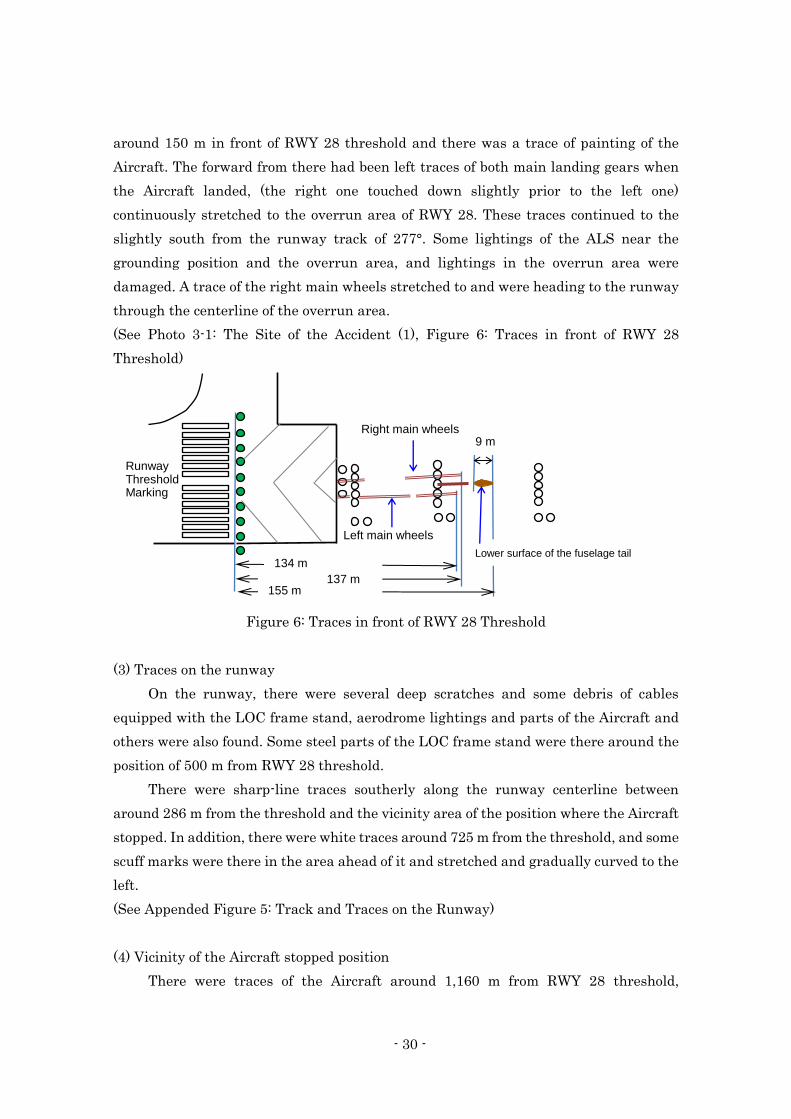
- 30 -
around 150 m in front of RWY 28 threshold and there was a trace of painting of the
Aircraft. The forward from there had been left traces of both main landing gears when
the Aircraft landed, (the right one touched down slightly prior to the left one)
continuously stretched to the overrun area of RWY 28. These traces continued to the
slightly south from the runway track of 277°. Some lightings of the ALS near the
grounding position and the overrun area, and lightings in the overrun area were
damaged. A trace of the right main wheels stretched to and were heading to the runway
through the centerline of the overrun area.
(See Photo 3-1: The Site of the Accident (1), Figure 6: Traces in front of RWY 28
Threshold)
Figure 6: Traces in front of RWY 28 Threshold
(3) Traces on the runway
On the runway, there were several deep scratches and some debris of cables
equipped with the LOC frame stand, aerodrome lightings and parts of the Aircraft and
others were also found. Some steel parts of the LOC frame stand were there around the
position of 500 m from RWY 28 threshold.
There were sharp-line traces southerly along the runway centerline between
around 286 m from the threshold and the vicinity area of the position where the Aircraft
stopped. In addition, there were white traces around 725 m from the threshold, and some
scuff marks were there in the area ahead of it and stretched and gradually curved to the
left.
(See Appended Figure 5: Track and Traces on the Runway)
(4) Vicinity of the Aircraft stopped position
There were traces of the Aircraft around 1,160 m from RWY 28 threshold,
134 m 137 m
155 m
9 m
Lower surface of the fuselage tail
Right main wheels
Left main wheels
Runway Threshold Marking
- 31 -
indicating it veered from the runway to the left (to the south). In the grass area ahead of
it, three line traces were stretching to the vicinity of where the Aircraft stopped. Just in
front of there, several large and deep traces were dug; accordingly, they revealed that
the nose of the Aircraft came to ground with veering to the left.
The Aircraft came to a stop, heading for south-east in the runway strip: at the
position of around 1,480 m from RWY 28 threshold (around the central part of the 3,000
m long runway) by around 140 m south from the runway centerline (around 20 m in front
of the southern boundary of the Airport grounds abutting a cliff).
(See Photo 4: The Vicinity of the Aircraft Stop Position, Appended Figure 5: Track and
Traces on the Runway)
(5) Damage to aerodrome lightings
As shown in Figure 3, quite number of lights of SALS of RWY 28 were damaged:
one of the five cross-bar lights at 360 m in front of RWY 28 threshold, eight of 21 cross-
bar lights at 300 m, one of five cross-bar lights at 180 m, three of five cross-bar lights at
120 m, and two of five cross-bar lights at 60 m were damaged; accordingly, many of the
poles of those lights were damaged. The two Wide Approach Lights*45 at 300 m in front
of RWY 28 threshold and one of overrun area edge lights (ORL) in RWY 28 were damaged.
Other than those, one RCLL (embedded type) at 465 m from RWY 28 threshold and
one REDL in the south edge at 1,140 m from it were damaged.
2.11.2 Details of Damage of the Airframe
(1) The lower surface, the side surface and the fuselage tail
- There were considerable damages such as breakings, scratches, cracks, holes and
dents.
- Electrical wirings were broken and damaged.
- The Aircraft Radio Altimeter antenna have been stripped out.
- Left side surface was damaged by a steel frame of the LOC frame stand stuck in.
- Some access doors were dropped off and damaged.
(2) Main wings
- Inboard and outboard of flaps and flap tracks were damaged.
- An outboard flap of right main wing was partially fractured, and a part of the
LOC frame stand and antenna cables were wound around the right outboard
flaps.
*45 "Wide Approach Lights (WALS)" is the lightings used for a circling approach.
- 32 -
- Left main wing tip was damaged.
(3) Main landing gears
- Some steel frames of the LOC frame stand and the cables were wound around
both main landing gears.
- Air-ground sensors of main landing gears were damaged and the electrical wirings
of the gears were broken.
- Hydraulic lines (for brakes) were broken.
- Shock-struts of main landing gears were compressed to the bottom and had some
cracks in the cylinders.
- Down-lock stay in the left main landing gear was broken. (Nose gears and the
right main landing gear were secured in the down-locked position, while the left
main landing gear was superficially extended nevertheless it was not secured in
the down-locked position.)
- Gear well door of left main landing gear was damaged. Outside of it had a tire
mark.
- Outboard tires of the left main landing gear was detached from the wheel and
seriously damaged.
- Inboard tires of the left main landing gear rubber was peeled off.
- Inboard and outboard tires of the right main landing gear were damaged.
(4) Engine
- There were some scars of impact with the LOC frame stand around the intake
areas of both engines.
- Fan blades, low-pressure compressor blades and those circumferential parts in
both engines were seriously damaged.
- The lower cowl of No. 1 (the left) Engine was seriously damaged.
- A left engine cowl of No.1 Engine was partially fallen off.
- The pylon of No. 1 Engine was damaged.
- The pylon of No. 2 (the right) Engine and its peripheral of the lower surface of the
right main wing were blackened with soot.
(5) Horizontal stabilizer
- The left horizontal stabilizer was fractured.
- The leading edge of the right horizontal stabilizer was damaged. (Stuck with the
steel frame of the LOC frame stand)
- 33 -
2.11.3 Situation in the Cockpit and Cabin
The investigation revealed the following:
(1) Situation in the cockpit
- Thrust levers: "0" (idle position)
- Speed brake lever: "RET"(retracted) and "ARMED"
(automatically extended after touchdown)*46
- Flap lever: "FULL" (full down)
- Parking brake: "ON"
- Engine master switches: "OFF" (both Engines)
- Engine fire buttons: "PUSH"
- APU fire button: "PUSH"
- Emergency escape panel:
COMMAND pb*47: The operational status of the button could
not be confirmed.
CAPT and CAPT/PURS sw*48 "CAPT"
- Circuit breakers:
"CVR-CTL" and "CVR-SPLY": Pop out
"Brake temperature detecting unit": Pop out
- ND settings (The same settings for the PIC and the FO)
Display: "ARC"
Range: "10"
Both of NAV 1 and NAV 2: "VOR"
It should be noted that the instrument displays or the situation of the
warning lights could not be confirmed because electric power could not be
supplied with the Aircraft.
(2) Situation in the cabin
The five panel doors of oxygen mask units were left open (Seat A, B and C in the
7th row, Seat D, E and F in the 11th row, Seat D, E and F in the 18th row, Seat D, E and
F in 21st row and in aft galley), and the oxygen masks dropped. As well as in the cockpit,
the operational status of PA, interphone systems and others could not be confirmed
because electric power could not be supplied with the Aircraft.
*46 The setting position of the lever was "RET" and "ARMED" (automatically extended after touchdown) status.
*47 "COMMAND pb" is the button that lets warning signal (horn) sound to instruct emergency evacuation.
*48 See 2.15.4 for "CAPT and CAPT/PURS sw"
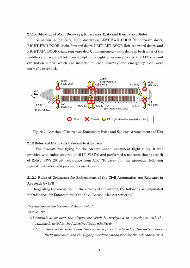
- 34 -
2.11.4 Situation of Main Doorways, Emergency Exits and Evacuation Slides
As shown in Figure 7, main doorways: LEFT FWD DOOR (left forward door),
RIGHT FWD DOOR (right forward door), LEFT AFT DOOR (left rearward door), and
RIGHT AFT DOOR (right rearward door), and emergency exits doors in both sides of the
middle cabin were all let open except for a right emergency exit of the 11th row and
evacuation slides, which are installed in each doorway and emergency exit, were
normally extended.
Figure 7: Location of Doorways, Emergency Exits and Seating Arrangements of FAs
2.12 Rules and Standards Relevant to Approach
The Aircraft was flying for the Airport under instrument flight rules. It was
provided with radar-vectored until IF (VISTA) and performed a non-precision approach
of RNAV RWY 28 with clearance from ATC. To carry out this approach, following
regulations, rules, and procedures are defined:
2.12.1 Rules of Ordinance for Enforcement of the Civil Aeronautics Act Relevant to
Approach by IFR
Regarding the navigation in the vicinity of the airport, the following are stipulated
in Ordinance for Enforcement of the Civil Aeronautics Act (excerpts):
(Navigation in the Vicinity of Airport etc.)
Article 189
(1) Aircraft at or near the airport etc. shall be navigated in accordance with the
standards listed in the following items. (Omitted)
(i) The aircraft shall follow the approach procedure based on the instrumental
flight procedure and the flight procedure established for the relevant airport
Purser (L1A)
FA (L1B) FA (Exit Row Seat: 11C)
FA (L2)
FA (R2)
Right FWD door
Raw 11 Raw 12
FA: flight attendant (seated position) : Open : Closed
Left FWD door
Right AFT door
Left AFT door
Cabin EMERGENCY EXITS
FWD
- 35 -
etc. (Omitted)
(iii) The landing approach shall not be continued when the Instrumental Flight
Rules is being used for landing and one of the conditions listed below exists:
(omitted)
(a) The meteorological condition does not meet the minimum condition for
continuing the landing approach at the relevant airport when the aircraft
passes above the approach height threshold at a specified location.
(b) The position of the aircraft cannot be identified by visual references which
should have been in view and identified continuously at or below the approach
height threshold.(omitted)
(2) The Minister of Land, Infrastructure, Transport and Tourism shall establish for
each airport the flight method for item (i) of the previous paragraph, the
meteorological conditions in accordance with the provisions in items (ii) and (iii) of
the same paragraph and the approach height threshold, the specific location at a
higher altitude than the approach height threshold and visual landmarks in
accordance with item (iii) of the same paragraph.
2.12.2 Rules of Annex 6 to the Convention on International Civil Aviation (Chicago
Convention)
The following rules are defined in Annex 6 to the Convention on International Civil
Aviation (Operation of Aircraft) (excerpts):
Chapter 1. DEFINITIONS
Decision altitude (DA) or Decision height (DH)
A specified altitude or height in a 3D instrument approach operation at which a
missed approach must be initiated if the required visual reference to continue the
approach has not been established.
Note 2. - The required visual reference means that section of the visual aids or of
the approach area which should have been in view for sufficient time for the pilot
to have made an assessment of the aircraft position and rate of change of positions,
in relation to the desired path.
2.12.3 Continuing Approach by Instrument Approach Procedures described in AIP
Continuing approach by Instrument Approach Procedures is stipulated in ENR 1.5
of AIP*49 as follows (excerpts):
*49 "AIP" stands for aeronautical information publication published by State. It contains permanent information
required for aircraft operation.
- 36 -
2.1.1.5 After commenced an instrument approach (after determined continuation
of approach beyond predetermined point such as FAF, OM, 1,000 ft above
aerodrome elevation or other points accepted by the authority *50), if the
weather conditions at the airport of intended landing has worsened to
below published or pilot's minima, he may continue an instrument
approach down to the DA/H or MDA/H, and an approach to land may be
continued if he, upon reaching the DA/H or MDA/H, finds the actual
weather conditions are at or above the lowest weather condition for
landing*51
NOTE: < from AIP AD 1.1 6.10.1(a) >
Pilot may continue the approach below DA/H or MDA/H provided that the
required visual reference is established at the DA/H or MDA/H and is
maintained in order that the landing might be completed. The required
visual references are as follows:
(a) For non-precision approach, ILS approach (CAT I) and PAR approach,
at least one of the followings:
i) Elements of approach light system
ii) Threshold
iii) Threshold markings
iv) Threshold lights
v) Threshold identification light
vi) Precision approach path indicator
vii) Touchdown zone or touchdown zone markings
viii) Touchdown zone lights
ix) Runway edge lights
x) Other visual reference accepted by the authority
(omitted)
2.12.4 RNAV (GNSS) RWY 28 Approach Procedure in AIP
As shown in Appended Figure 7, final approach course for RNAV RWY 28 approach
procedure is 277° as same as that of runway track, descent path angle 3°, and DA is
*50 “Operating minima for continuation of approach, which are applied to the determination whether approach may
be continued beyond the predetermined point such as FAF, OM, 1000ft above aerodrome elevation or other points
accepted by the authority,” are defined as RVR. Converted Meteorological Visibility (CMV) is applied instead when,
and only when, RVR is not available.
*51 See AIP AD 1.1-34, 6.10.1 for “The lowest weather condition for landing.
- 37 -
1,500 ft (HAT 433 ft). As the Aircraft belongs to the Category C described in the bottom
table of Appended Figure 7 and capable of performing LNAV/VNAV (approach with
horizontal and vertical guidance), it comes up with state minima*52 and the aerodrome
weather minimum is RVR: 1,400 m.
(See Appended Figure 7: RNAV (GNSS) RWY 28 Approach Chart)
2.12.5 Baro-VNAV Approach Operational Standard
When the accident occurred, the Aircraft was performing RNAV RWY 28 approach,
which is Baro-VNAV approach: Barometric Vertical Navigation for instrument
approach, established in RWY 28 at the Airport.
Baro-VNAV Approach Operational Standard*53, defined by Japan Civil Aviation
Bureau of the Ministry of Land, Infrastructure, Transport and Tourism (hereinafter
referred to as "JCAB") stipulates as follows: as equipment requirement, an aircraft must
be equipped with integrated RNAV*54 system with VNAV functions*55 approved for
Instrument Approach Procedure; as operational equipment, pilots must use FD or
AP/FD when flying a vertical path based on VNAV*56; pilots must fly, correctly adjusting
the aircraft altimeter for a current local QNH of the airport where VNAV approach is
going to be performed and other regulations. Besides, as for operator requirement, it is
stipulated that operators must define required items in the operation manuals and rules,
they must provide the pilots with required knowledge by offering educations for
determination when vertical deviations occurred, they must carry out sufficient training
on the aircraft VNAV capabilities including confirmations of operational procedure, to
the extent that the pilots will not be just task oriented. In addition, as requirements for
operations of foreign registered aircraft, they must obtain an approval from the authority
of the State of Registry or the Operator that their Baro-VNAV Instrument Approach
Procedures operation comply with the requirements that are equivalent to this
standards.
*52 "State minima" is operation condition minima officially announced in AIP.
*53 "Baro-VNAV approach operational standard," stipulated by JCAB conforming to Doc. 9613: Performance-based
Navigation Manual (hereinafter referred to as "PBN manual") related to Annex 6 to the Convention on International Civil Aviation, was officially published in AIC04/08 when the accident occurred.
*54 "RNAV" indicates area navigation.
*55 "VNAV function" is a function to navigate for vertical element of flight. *56 The Standard states that since vertical deviation scaling and sensitivity varies widely, eligible aircraft must also
be equipped with and operationally using either FD or AP/FD capable of following the vertical path.
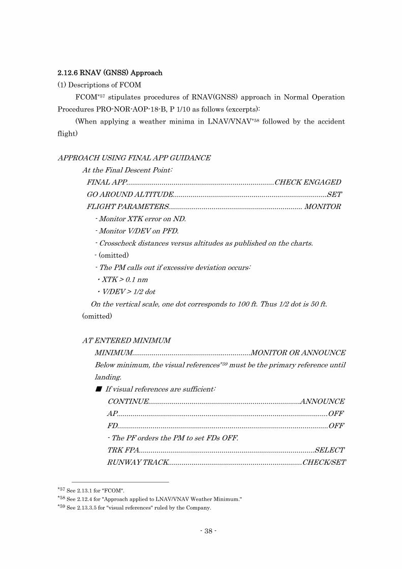
- 38 -
2.12.6 RNAV (GNSS) Approach
(1) Descriptions of FCOM
FCOM*57 stipulates procedures of RNAV(GNSS) approach in Normal Operation
Procedures PRO-NOR-AOP-18-B, P 1/10 as follows (excerpts):
(When applying a weather minima in LNAV/VNAV*58 followed by the accident
flight)
APPROACH USING FINAL APP GUIDANCE
At the Final Descent Point:
FINAL APP...........................................................................CHECK ENGAGED
GO AROUND ALTITUDE..............................................................................SET
FLIGHT PARAMETERS.................................................................... MONITOR
- Monitor XTK error on ND.
- Monitor V/DEV on PFD.
- Crosscheck distances versus altitudes as published on the charts.
- (omitted)
- The PM calls out if excessive deviation occurs:
・XTK > 0.1 nm
・V/DEV > 1/2 dot
On the vertical scale, one dot corresponds to 100 ft. Thus 1/2 dot is 50 ft.
(omitted)
AT ENTERED MINIMUM
MINIMUM............................................................MONITOR OR ANNOUNCE
Below minimum, the visual references*59 must be the primary reference until
landing.
■ If visual references are sufficient:
CONTINUE.............................................................................ANNOUNCE
AP...........................................................................................................OFF
FD...........................................................................................................OFF
- The PF orders the PM to set FDs OFF.
TRK FPA.........................................................................................SELECT
RUNWAY TRACK....................................................................CHECK/SET
*57 See 2.13.1 for "FCOM".
*58 See 2.12.4 for "Approach applied to LNAV/VNAV Weather Minimum." *59 See 2.13.3.5 for "visual references" ruled by the Company.
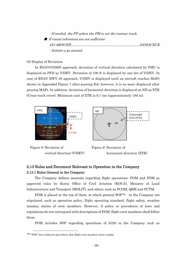
- 39 -
- If needed, the PF orders the PM to set the runway track.
■ If visual references are not sufficient:
GO AROUND...........................................................................ANNOUNCE
- Initiate a go around.
(2) Display of Deviation
In RNAV(GNSS) approach, deviation of vertical direction calculated by FMC is
displayed on PFD as V/DEV. Deviation of 100 ft is displayed by one dot of V/DEV. In
case of RNAV RWY 28 approach, V/DEV is displayed until an aircraft reaches MAPt
shown in Appended Figure 7 after passing DA; however, it is no more displayed after
passing MAPt. In addition, deviation of horizontal direction is displayed on ND as XTK
(Cross-track error). Minimum unit of XTK is 0.1 nm (approximately 180 m).
2.13 Rules and Document Relevant to Operation in the Company
2.13.1 Rules General in the Company
The Company defines manuals regarding flight operations: FOM and POM as
approved rules by Korea Office of Civil Aviation (KOCA), Ministry of Land
Infrastructure and Transport (MOLIT), and others such as FCOM, QRH and FCTM.
FOM is placed at the top of them, in which general SOP*60 in the Company are
stipulated, such as operation policy, flight operating standard, flight safety, weather
minima, duties of crew members. However, if policy or procedures of laws and
regulations do not correspond with descriptions of FOM, flight crew members shall follow
them.
POM includes SOP regarding operations of A320 in the Company such as
*60 "SOP" here indicates procedures that flight crew members must comply.
.5R
Cross-track
Error (XTK)
ND
1.0 dot
PFD
V/DEV
Figure 8: Deviation of
vertical direction (V/DEV)
Figure 9: Deviation of
horizontal direction (XTK)
- 40 -
procedures, performances, operations in adverse weather, Category II/III flight
operation. All subjects that are not included in POM, should be referred to other manuals
relevant to flight operations. Flight crew members should follow the restrictions stated
in POM when it is more restricted than other flight operational manuals such as FOM.
Moreover, FCOM describes normal and emergency operation procedures the
manufacturer of the type of the aircraft (hereinafter referred to as "the Type")
recommends, besides operating limitations, performances, system descriptions, and
others. QRH describes normal and abnormal/emergency procedures in format of
checklists. Furthermore, FCTM supplements FCOM and provides pilots with practical
information on how to operate the Type; it should be compared with to FCOM. However,
in the case of any conflict, the FCOM is the over-riding authority.
2.13.2 Rules and Policy in FOM
2.13.2.1 Landing Minima
FOM stipulates the Company minima*61 in 6.1.3. Landing Minima as follows
(excerpts):
6.1.3.1 Application of Landing Minima
(omitted)
b. Landing Minima shall be applied to whichever is higher of the local published
minima in Route Guide (Airway Manual) and Company Minima.
(omitted)
6.1.3.4 Minima for Non-Precision Approaches
Approach Facility
Touchdown Zone (TDZ)
RVR/Visibility Remarks
Category C
Localizer approach (LOC)
(with ALS)
Published MDA
800 m (2,400 ft)/800 m Use Mid RVR if TDZ RVR
is not available.
Others
(LOC, VOR, NDB, ASR)
Published MDA
1,600 m (5,000 ft)/1,600 m Use Mid RVR if TDZ RVR
is not available.
*61 "Company minima" is aerodrome weather minimum that each operator defines for its aircraft. It is a setting for
an aircraft according to each runway and each approach procedure to be used. Some restrictions may be added
depending on flight experience of the PIC, Category ILS approach qualification and so on.
- 41 -
2.13.2.2 Switching to Manual Flight Operation
FOM stipulates transfer procedure from autopilot to manual flight in 2.2
Controlling Airplane as follows (excerpts):
2.2.2.3 Manual Flight Operation Guidelines
a. The point of switching between Autopilot and Manual Flight should be decided
considering the weather condition and air traffic, workload in the cockpit, skill
of the PF and comfort of the passengers, etc.
(omitted)
d. Although the flight has utilized automation system in approach phase, when
decided to perform manual landing, PF can disengage autopilot before 1,000
feet for the adoption of the control.
2.13.2.3 Missed Approach (Go-Around)
FOM stipulates missed approach (go-around) procedure in 7.11 Missed
Approach/Go-Around as follows (excerpts):
7.11.2 Performing Missed Approach (Go-Around)
a. Missed approach (go-around) is one of the primary method of ensuring flight
safety, it is essential for the flight crew to make precise decision and perform
proper procedure.
b. Do not hesitate to perform missed approach (go-around). Missed approaches
and go-arounds are part of a normal procedure for flight safety. This maneuver
should not be understood as correcting a mistake.
c. Determination to perform Missed Approach (Go-Around) shall be made by
1) Above 1,000 ft: PIC’s decision.
2) Below 1,000 ft: Any flight crew member in the cockpit (both operating and
non-operating) calls out “GO-AROUND”, PF must perform
GO-AROUND without hesitation.
d. Refer to type POM for conditions to perform missed approach (go-around) and
descent procedure below DA/DH, MDA and etc.
2.13.2.4 Use of Radio Altimeter
FOM stipulates the use of radio altimeter in 7.8 Approach as follows (excerpts):
7.8.8 Barometric Setting
(omitted)
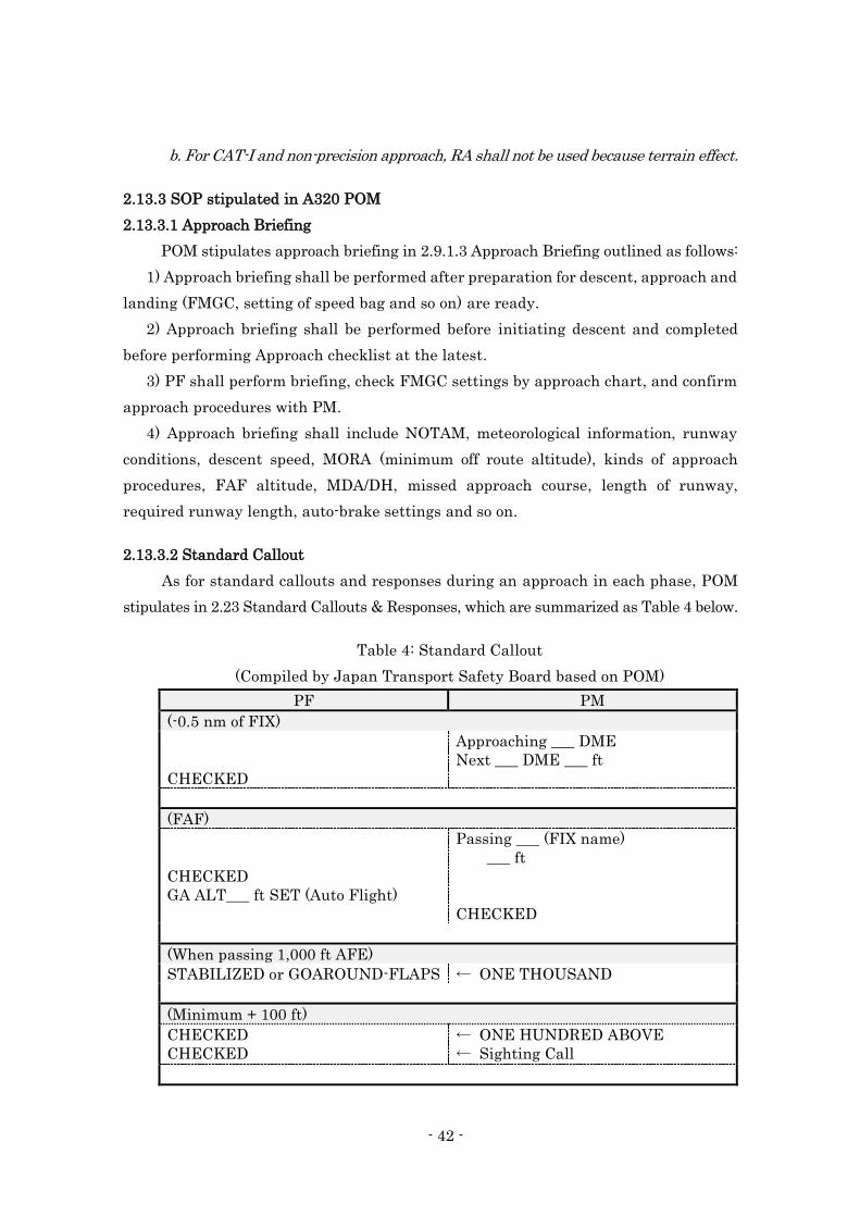
- 42 -
b. For CAT-I and non-precision approach, RA shall not be used because terrain effect.
2.13.3 SOP stipulated in A320 POM
2.13.3.1 Approach Briefing
POM stipulates approach briefing in 2.9.1.3 Approach Briefing outlined as follows:
1) Approach briefing shall be performed after preparation for descent, approach and
landing (FMGC, setting of speed bag and so on) are ready.
2) Approach briefing shall be performed before initiating descent and completed
before performing Approach checklist at the latest.
3) PF shall perform briefing, check FMGC settings by approach chart, and confirm
approach procedures with PM.
4) Approach briefing shall include NOTAM, meteorological information, runway
conditions, descent speed, MORA (minimum off route altitude), kinds of approach
procedures, FAF altitude, MDA/DH, missed approach course, length of runway,
required runway length, auto-brake settings and so on.
2.13.3.2 Standard Callout
As for standard callouts and responses during an approach in each phase, POM
stipulates in 2.23 Standard Callouts & Responses, which are summarized as Table 4 below.
Table 4: Standard Callout
(Compiled by Japan Transport Safety Board based on POM)
PF PM
(-0.5 nm of FIX)
CHECKED
Approaching ___ DME
Next ___ DME ___ ft
(FAF)
CHECKED
GA ALT___ ft SET (Auto Flight)
Passing ___ (FIX name)
___ ft
CHECKED
(When passing 1,000 ft AFE)
STABILIZED or GOAROUND-FLAPS ← ONE THOUSAND
(Minimum + 100 ft)
CHECKED
CHECKED
← ONE HUNDRED ABOVE
← Sighting Call
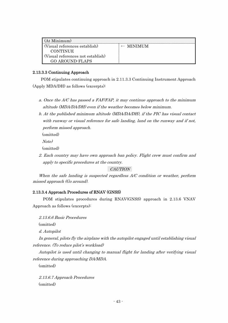
- 43 -
(At Minimum)
(Visual references establish)
CONTINUE
(Visual references not establish)
GO AROUND-FLAPS
← MINIMUM
2.13.3.3 Continuing Approach
POM stipulates continuing approach in 2.11.3.3 Continuing Instrument Approach
(Apply MDA/DH) as follows (excerpts):
a. Once the A/C has passed a FAF/FAP, it may continue approach to the minimum
altitude (MDA/DA/DH) even if the weather becomes below minimum.
b. At the published minimum altitude (MDA/DA/DH), if the PIC has visual contact
with runway or visual reference for safe landing, land on the runway and if not,
perform missed approach.
(omitted)
Note)
(omitted)
2. Each country may have own approach ban policy. Flight crew must confirm and
apply to specific procedures at the country.
CAUTION
When the safe landing is suspected regardless A/C condition or weather, perform
missed approach (Go around).
2.13.3.4 Approach Procedures of RNAV (GNSS)
POM stipulates procedures during RNAV(GNSS) approach in 2.13.6 VNAV
Approach as follows (excerpts):
2.13.6.6 Basic Procedures
(omitted)
d. Autopilot
In general, pilots fly the airplane with the autopilot engaged until establishing visual
reference. (To reduce pilot’s workload)
Autopilot is used until changing to manual flight for landing after verifying visual
reference during approaching DA/MDA.
(omitted)
2.13.6.7 Approach Procedures
(omitted)
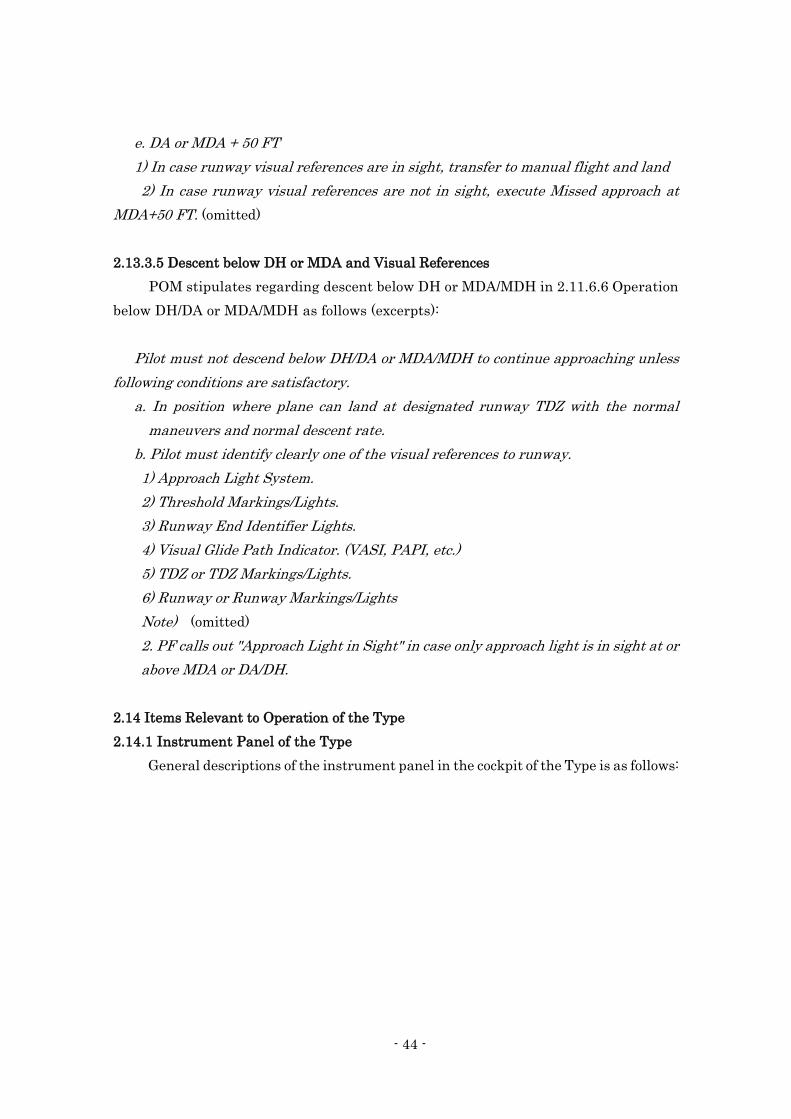
- 44 -
e. DA or MDA + 50 FT
1) In case runway visual references are in sight, transfer to manual flight and land
2) In case runway visual references are not in sight, execute Missed approach at
MDA+50 FT. (omitted)
2.13.3.5 Descent below DH or MDA and Visual References
POM stipulates regarding descent below DH or MDA/MDH in 2.11.6.6 Operation
below DH/DA or MDA/MDH as follows (excerpts):
Pilot must not descend below DH/DA or MDA/MDH to continue approaching unless
following conditions are satisfactory.
a. In position where plane can land at designated runway TDZ with the normal
maneuvers and normal descent rate.
b. Pilot must identify clearly one of the visual references to runway.
1) Approach Light System.
2) Threshold Markings/Lights.
3) Runway End Identifier Lights.
4) Visual Glide Path Indicator. (VASI, PAPI, etc.)
5) TDZ or TDZ Markings/Lights.
6) Runway or Runway Markings/Lights
Note) (omitted)
2. PF calls out "Approach Light in Sight" in case only approach light is in sight at or
above MDA or DA/DH.
2.14 Items Relevant to Operation of the Type
2.14.1 Instrument Panel of the Type
General descriptions of the instrument panel in the cockpit of the Type is as follows:
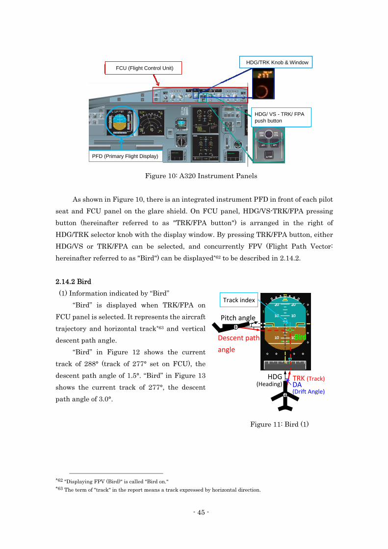
- 45 -
FCU (Flight Control Unit) HDG/TRK Knob & Window
HDG/ VS - TRK/ FPA push button
PFD (Primary Flight Display)
Figure 10: A320 Instrument Panels
As shown in Figure 10, there is an integrated instrument PFD in front of each pilot
seat and FCU panel on the glare shield. On FCU panel, HDG/VS-TRK/FPA pressing
button (hereinafter referred to as "TRK/FPA button") is arranged in the right of
HDG/TRK selector knob with the display window. By pressing TRK/FPA button, either
HDG/VS or TRK/FPA can be selected, and concurrently FPV (Flight Path Vector:
hereinafter referred to as "Bird") can be displayed*62 to be described in 2.14.2.
2.14.2 Bird
(1) Information indicated by “Bird”
“Bird” is displayed when TRK/FPA on
FCU panel is selected. It represents the aircraft
trajectory and horizontal track*63 and vertical
descent path angle.
“Bird” in Figure 12 shows the current
track of 288° (track of 277° set on FCU), the
descent path angle of 1.5°. “Bird” in Figure 13
shows the current track of 277°, the descent
path angle of 3.0°.
*62 "Displaying FPV (Bird)" is called "Bird on."
*63 The term of "track" in the report means a track expressed by horizontal direction.
Figure 11: Bird (1)
HDG TRK (Track) DA (Drift Angle)
Pitch angle
Descent path
angle
(Heading)
Bird
Track index
2 2 2 2

- 46 -
(2) FCTM descriptions
FCTM*64 describes how to utilize “Bird” in SI-020 P 1/4 as follows (excerpts):
THE FLIGHT PATH VECTOR
When TRK/FPA is selected on the FCU, the "bird" (the FPV) is the flight
reference with the TRK and FPA as basic guidance parameters.
In dynamic maneuvers, the "bird" is directly affected by the aircraft inertia
and has a delayed reaction. As a result, the "bird" should not be used as a flight
reference in dynamic maneuvers.
The "bird" is the flying reference that should be used when flying a stabilized
segment of trajectory, e.g. a non-Precision Approach or visual circuit.
PRACTICAL USES OF THE FPV
As a general rule, when using the bird, the pilot should first change attitude,
and then check the result with reference to the bird.
NON-PRECISION APPROACH
The FPV is particularly useful for non-precision approaches. The pilot can
select values for the inbound track and final descent path angle on the FCU. Once
established inbound, only minor corrections should be required to maintain an
accurate approach path. The pilot can monitor the tracking and descent flight path,
with reference to the track indicator and the bird.
However, pilots should understand that the bird only indicates a flight path
*64 See 2.13.1 for "FCTM."
Figure 13: Bird (3) Figure 12: Bird (2)
Current track
1.5°
Gap of track Track index (Track being set on FCU)
26 27
28 29
Descent
path
angle
26 27 28 29
3.0° Descent
path
angle
- 47 -
angle and track, and does not provide guidance to a ground-based radio facility.
Therefore, even if the bird indicates that the aircraft is flying with the correct flight
path angle and track, this does not necessarily mean that the aircraft is on the
correct final approach path.
2.15 Emergency Evacuation
2.15.1 Periodical Trainings in the Company
The Company provides FAs with annual evacuation training in which they are
checked their knowledge about the usage of emergency equipment, the evacuation
procedures, handling hazardous goods, first-aid treatment and others, and given a
practical evacuation training.
Besides, it provides flight crew members in each type of aircraft annually with
the usage of emergency equipment, the procedure to open main doors and emergency
exits at an emergency situation in their ground school session. In addition, it provides
them with simulator recurrent trainings, in which an emergency evacuation practice
is provided. Both the PIC and the FO have been done these.
2.15.2 EMERGENCY EVACUATION Checklist
The PIC shall perform EMERGENCY EVACUATION Checklist in QRH when
executing emergency evacuation (excerpts):
EMERGENCY EVACUATION
AIRCRAFT/PARKING BRK…………………………………………… STOP/ON
ATC (VHF 1) …………………………………………………………………NOTIFY
CABIN CREW (PA) ………………………………………………………….ALERT
ΔP(only if MAN CAB PR has been used)…………………………CHECK ZERO
if not zero, MODE selector on MAN,V/S CTL FULL UP
ENG MASTERS (ALL) …………………………………………………….…..OFF
FIRE Pushbuttons (ALL : ENG and APU) …………………………….... PUSH
AGENTS (ENG and APU)…………………………………………….…AS RQRD
■If evacuation required:
EVACUATION ……………………………………………………………INITIATE
■If evacuation not required:
CABIN CREW and PASSENGERS (PA)………………..…………..… NOTIFY
- 48 -
2.15.3 FA’s Role in Emergency Evacuation
FCOM states regarding the success and failure in emergency evacuation that
crew members’ high knowledge and practical performance of their roles are key points.
FOM stipulates that FAs shall notify flight crew members of emergency situation
by interphone; if they cannot contact them, they shall try to report by any other ways
such as going to cockpit. It also stipulates that flight crew members shall promptly
respond to emergency notification from FAs. Further, it is stipulated that if flight crew
members do not take appropriate necessary measures in the situation where
emergency evacuation is surely required, the purser shall direct and execute it.
2.15.4 CAPT and PURS/CAPT Switch
The type of the Aircraft has equipped with CAPT and PURS/CAPT Selector Switch
for a command of Emergency Evacuation in the cockpit. Depending on the switch
position selected, when emergency evacuation is required, the emergency evacuation
warning signal may either activated only from the cockpit or both from the cockpit and
the cabin.
FCOM prescribes for the switch position to be set "as required" in the preliminary
cockpit preparation and an operator would have its discretion over the standard
position of the switch. The Company prescribed in POM that it shall be set in "CAPT":
an emergency evacuation can be activated only from the cockpit.
2.16 Information about Rescue and Firefighting Services
2.16.1 Emergency System at Airport when an Aviation Accident Occurs
(1) International standard relevant to rescue and fire fighting
Regarding rescue and firefighting activities (RFF activities) when aviation
accidents occur at airports, ICAO DOC-9137 Airport Services Manual (hereinafter
referred to as "Airport Services Manual") generally describes below, which is to secure
uniform application in the course of enforcing rules of Annex 14 (Aerodromes) to the
Convention on International Civil Aviation,
- The prime mission of the airport RFF (Rescue and Firefighting) service is to
control the fire in the critical area to be protected in any post-accident fire
situations with a view to permitting the evacuation of the aircraft occupants.
- The rescue must be taken to include protection of the routes followed by
occupants of the aircraft who are able to escape from the aircraft. The activities
external to the aircraft may include firefighting, the blanketing of fuel wetted
areas adjacent to the aircraft, the assistance in the effective use of the emergency
- 49 -
escape equipment deployed from the aircraft and the provision of lighting where
this would expedite the evacuation of the aircraft and the assembly of its
occupants in a safe area.
- It will be a duty of the airport RFF personnel to assist air crew in any way
possible. RFF personnel should take immediate steps to establish direct contact
between the pilots and the on-scene commander.
(2) “Hiroshima Airport Emergency Plan"
The Hiroshima airport office (hereinafter referred to as "the Office") stipulates
“Emergency Plan (hereinafter referred to as "the Plan") conformity to Annex 14
(Aerodromes) to the Convention on International Civil Aviation, which contains
activities preparing for the case of aircraft accident and others.
The Plan stipulates that when an emergency occurred, the Office shall notify the
relevant organizations with the urgent message and the request for RFF services by
Emergency Contact System*65 (hereinafter referred to as “the System”) separately
defined, moreover, it will organize "The Rescue and Firefighting Corps (hereinafter
referred to as "the RFF Corps")*66 with the cooperation of the relevant parties in the
airport to support RFF services performed by official agencies when it finds necessary.
Besides, the Plan stipulates that in preparation for the exercises against an
emergency situation involved with aircraft the Office shall collaborate with the relevant
organizations and implement a full-scale emergency exercise at least once every two
years; it shall take into consideration for meteorological conditions or the occurrence
time of emergency situation (at night) and other factors when planning for joint exercises
and large-scale exercises.
(3) Deployment of the emergency vehicles and Comprehensive trainings for RFF at the
Airport
The Airport is classified as Category-9 airport described in Annex 14
(Aerodromes) to the Convention on International Civil Aviation. Three chemical fire
engines, a water tank vehicle, an illumination vehicle, a vehicle for emergency
*65 "Emergency Contact System" is included in the Plan as an attachment: The Office is supposed to notify the
relevant organizations of the urgent message in sequence as follows: It shall notify, as the first report, the public
organizations of the Police and the Fire Fighting by a dedicated line, as the second the companies in the Airport and
CIQ offices and others, as the third the telecommunication company and the medical association, as the fourth the
airport construction office and the neighbor local government offices.
*66 "The Rescue and Firefighting Corps" is composed of three groups of rescue/ firefighting, first-aid and security.
The Airport Director of Hiroshima Airport serves as the commander. The role of each group is as follows: The
rescue/firefighting group supports for firefighting, handles a water wagon and an illumination vehicle and guides
passengers/crew members evacuated. The first-aid group establishes a first-aid station and carries the injured by
stretchers. The security group controls the traffic around the accident site.
- 50 -
medication are deployed. Seven airport RFF personnel were arranged when the
accident occurred.
In addition, following the Plan, a full-scale emergency exercise preparing for
aircraft accident was held at the Airport on October 16, 2013, in which 435 people from
54 organizations joined, such as personnel from the Office, the fire departments, Japan
Coast Guard, Hiroshima prefectural government office and others. According to the
records of exercises on and after 2008 at the Airport, the Office had not implemented
any full-scale emergency exercise under the assumption that accident occurred at night
or in an adverse condition like at night, except for operation trainings of fire engines.
2.16.2 RFF Activities and Actions taken by the Office
According to the records of the Office, actions taken by the Office and the activities
at the site after the accident occurred were outlined as follows:
The personnel in the command desk in the fire department building of the Office
(hereinafter referred to as “the Command desk”), who received an emergency call from
Hiroshima Tower with “Crash Phone,” immediately ordered the deployment of each
airport fire engines as the third-class dispatch*67 to the site. When the airport fire
engines arrived at the runway (around 20:07), no fire broke out, most of evacuated
occupants were heading for the International Terminal Building, and FAs were
providing guidance with a megaphone for evacuated occupants who were near the
Aircraft.
The airport firefighters got started providing evacuation guidance by onboard
microphones or beckon and performing safety check such as on-site investigation for fuel
leakage or fire detection.
The Office received reports that there were neither fuel leakage nor fire breakout
from an airport firefighter, and that all occupants on board had evacuated from an
aeronautical information officer *68 at the site of the accident.
From these report, the Office did not organize "The Rescue and Firefighting
Corps."
2.16.3 Accident Notifications from the Office
When taken together the information from the Office and the fire department of
*67 Deployment of fire engines in airport fire department were categorized into three classes in JCAB regulations:
The first-class dispatch (Stand-by phase), the second-class dispatch (Dangerous situation arising phase) and the
third-class dispatch (Actual accident phase).
*68 “Aeronautical information officer” is responsible for safe and smooth operations of aircraft at the airport and
performs tasks of collecting and providing essential information for daily flight operations, approving items relevant
to flight operations, working operational matters about the airport and managing airport safety.
- 51 -
local government office, accident notifications from the Office to the relevant
organizations are summarized as below.
At 20:07, after receiving an emergency call with "Crash Phone," the Command desk
notified the Operations Center in the neighbor local government offices (hereinafter
referred to as “the Operation Center”) and the Police of the accident of the Aircraft. The
Operation Center received that an arrival aircraft seemed to contact the fuselage tail
with the runway and personnel saw a pillar of flame blazing up, the airport fire engines
deployed; the fire, in this moment, seemed to be subdued; this was delivered only for
provision of information. Therefore, The Operation Center dispatched fire vehicles for
investigation*69. At 20:26, the Command desk provided information to the relevant
airlines, the owner company of airport building and Japan Coast Guard with information
respectively; however, it did not notify other relevant organizations*70 in accordance
with the System.
At 20:29, when fire engines of the fire department of local government office arrived
at the site of the accident, passengers and crew members had already evacuated to the
International Terminal Building. At 20:33, a staff member of the airport requested the
dispatch of the ambulances to the Operation Center; accordingly, the ambulance arrived
at the International Terminal Building at 20:48 and they initiated their rescue activities.
2.17 Additional Information
2.17.1 Trainings and Examinations for Flight Crew Members and the Status of Follow-
up
(1) Status of training and examinations for the PIC and the FO before the accident
occurred
- The PIC
February 5, 2013 Evaluation to qualify A320 type rating (simulator)
April 15, 2013 Route Check
November 4, 2013 Evaluation to certify as a captain (simulator)
January 14, 2014 Route Check
April 9, 2014 Ground school training including CRM
May 5, 2014 Recurrent training including emergency evacuation
(simulator)
*69 “Dispatch for investigation” is a style of dispatch of fire department, which intends to confirm the situation when
they discovered or received information about suspicious something like smoke, not so easy to be determine as a fire
breakout.
*70 To carry out “notifying the relevant organizations,” the Office was preparing for the system that enabled to
broadcast all together.
- 52 -
May 6, 2014 Proficiency check including emergency evacuation
(simulator)
October 16, 2014 Ground school training including CRM
November 1, 2014 Recurrent training (simulator)
November 2, 2014 Proficiency check (simulator)
November 3, 2014 Line Oriented Flight Training (LOFT)*71 (simulator)
February 15, 2015 Route Check
March 26, 2015 Ground school training including CRM
- The FO
March 7, 2013 Evaluation to qualify for A320 type rating
(simulator)
May 29, 2013 Route Check
September 20, 2013 Recurrent training including emergency evacuation
(simulator)
February 25, 2014 Ground school training including CRM
March 30, 2014 Proficiency check including emergency evacuation
included (simulator)
March 31, 2014 Recurrent training including emergency evacuation
(simulator)
May 30, 2014 Route Check
August 20, 2014 Ground school training including CRM
September 10, 2014 Recurrent training (simulator)
September 11, 2014 Proficiency check (simulator)
September 12, 2014 LOFT (simulator)
March 2, 2015 Proficiency check (simulator)
March 3, 2015 Recurrent training (simulator)
February 26, 2015 Ground school training including CRM
Follow-up systems in the Company
In the simulator or route training, the Company provides flight crew members with
debriefings among instructors and flight crew members in training to review the matters
noted in the session. In addition, it organizes a follow-up system, where in case that a
certain flight crew member in training received a comment to be improved, the instructor
*71 LOFT is a training using simulator, in which flight crew members could learn how to properly handle various
situations, while simulating regular flight operations, to make a practical use of knowledge and methods in CRM.
- 53 -
who has responsible for him or her in the next training can share contents of the
comment through electronic data.
The assessments of evaluation of the PIC in recent recurrent trainings and
proficiency check were generally "Good," and he had received some comments regarding
non-compliance with the rules; however, he was assessed "Good" after having an
additional attempt within a designated examination period of time. While, the FO had
"Good" assessments with no particular comments.
2.17.2 CRM Skills
"Crew Resource Management: An Introductory Handbook" (hereinafter referred to
as "CRM HDBK") published by Federal Aviation Administration describes that CRM
skills*72 are classified in "Communication Processes and Decision Making," "Team
Building and Maintenance" and "Workload Management and Situational Awareness".
Among those, it describes the necessity of "Assertiveness", which is an element of
"Communication Processes and Decision Making" on ground of followings: There are
number of instances in which crew members failed to speak up even when they had
critical flight information that might have averted a disaster; in these cases, crew
members were often unwilling to state an opinion or take a course of action even when
the operation of the airplane was clearly outside acceptable parameters. In addition, it
describes that "Assertiveness" includes skill elements as follows (excerpts):
・Inquiry: inquiring about actions taken by others and asking for clarification when
required.
・Advocacy: the willingness to state what is believed to be a correct position and to
advocate a course of action consistently and forcefully.
・Assertion: stating and maintaining a course of action until convinced otherwise by
further information.
Besides, CRM HDBK describes on "Leadership", which is an element of "Team
Building and Maintenance": Leadership skill is not relevant only to the captain, but each
flight crew member must play a role of a functional leader who takes on his or her own
responsibility assigned during take-off and landing or other phases. In addition,
*72 CRM HDBK describes that elements of CRM skills shall be not just knowledge but practical tools in regular
flight operations, and that CMR trainings must corresponds with operator’s needs and goals, in which operators
should try to have flight crew members acquire basic CMR skills at the recognizing session in the ground school,
master them at the practicing and feed-backing session, where LOFT is said to be most appropriate, maintain them
at the reinforcing sessions through such as periodic recurrent trainings.
- 54 -
leadership would more appropriately be called leadership/followership: Leadership is a
reciprocal process, and requires both leader actions and effective crew member
responses; Effective leaders perform following functions: asking for opinions or
suggestions, reassuring mutual communication, providing feedback towards response
from the follower, promoting good relationship between crew members and creating and
maintaining positive environment to have crew members participate in their flight
operation with full efforts.
2.17.3 Importance of SOP Compliance
"Strengthen Procedural Compliance" is a theme of "the Most Wanted List*73 in
2015," which was advocated by NTSB in U.S., generally being described as below.
The issue is finding ways to strengthen procedural compliance, from rooting
out inadequate company procedures, to ensuring comprehensive training, to
reemphasizing and reinforcing crew compliance. Recent accidents underscore the
importance of procedural compliance. (omitted)
Both air carrier management and professional pilots must put safety first.
Collective and collaborative leadership of company officers, pilots, and especially
captains is needed to promote and reinforce a culture of compliance - a culture
essential to safety. (omitted)
Better procedures, training, and compliance can help ensure a culture of safety.
2.17.4 Rules in Japan Relevant to Air Traffic Control
ATC Procedures for the Controller in Japan is defined by JCAB in Ⅲ Standards
for Air Traffic Control Procedure, Fifth Air Traffic Services Procedure Handbook of Air
Traffic Services Procedure Handbook.(hereinafter referred to as "the Standards")
2.17.4.1 Selection of Runway in Use
Selection of runway in use is stipulated at "1 General Rules (6), III Aerodrome
Control Procedure" in the Standards as below. (excerpts)
Departure runways or landing runways shall be selected according to the
following criteria. Provided; however, that this shall not apply when selection
*73 「The Most Wanted List」is a yearly list of prioritized issues which NTSB advocates to secure transportation
safety improvements. It is designed to increase awareness of, and support for, the most critical changes needed to
reduce transportation accidents and save lives.
- 55 -
according to the criteria is not desirable for reasons such as the length of runways,
flight routes, noise abatement or landing aid aids, or when aircraft requests to use
another runway.
(a) When the surface wind velocity is not less than 5 kt, the runway whose
orientation is closest to the wind direction is designated.
(b) When the surface wind velocity is less than 5 kt and a calm wind runway is
designated as appropriate.
A calm wind runway is not designated at the Airport.
2.17.4.2 Reporting of RVR Value
Reporting of RVR Value is stipulated at in "3 Meteorological information (4), I
General Rules" in the Standards as below. (excerpts)
a The time of report
Arriving aircraft ( limited to aircraft that makes instrument approach for which RVR
value is set as the minimum meteorological conditions to allow continued
approach ( excluding aircraft landing by circling approach))
(i) When initial communication is established or at the earliest time possible after that
time;
(ii) When approach clearance is issued or relayed, or at the earliest time possible after
radar approach is commenced;
(iii) When landing clearance is issued or relayed; however, the report may be omitted
when there is no change in the value already reported.
(iv) When RVR value has changed from the reported value. In this case, it shall be
reported to the extent which is practicable.
b RVR value
(omitted)
(d) When more than one observation equipment are installed and if any of their RVR
values is 1,800 meter or less: all the RVR that have been observed; In this case, values
shall be reported in the order of touchdown RVR value, mid-point RVR value, stop-
end RVR value.
- 56 -
2.17.5 ICAO rules Relevant to Air Control
PANS-ATM*74, in which procedures to complement Annex 11 to the Convention on
International Civil Aviation (Air Traffic Services), are described, stipulates about
reporting for arriving aircraft on a final approach as below. (excerpts)
6.6 INFORMATION FOR ARRIVING AIRCRAFT
6.6.5 During final approach, the following information shall be transmitted without
delay:
a) the sudden occurrence of hazards (e.g. unauthorized traffic on the
runway);
b) significant variations in the current surface wind, expressed in terms of
minimum and maximum values;
c) significant changes in runway surface conditions;
d) changes in the operational status of required visual or non-visual aids;
e) changes in observed RVR value(s), in accordance with the reported scale
in use, or changes in the visibility representative of the direction of
approach and landing.
The Standards stipulates about the timing of the reporting RVR value that " In this
case, it shall be reported to the extent which is practicable," adding a specific description
which is not including in PANS-ATM. JCAB states about adding in the Standards as
below.
There are some cases in a practical operational situation, for example, the case
where he or she must handle several aircraft simultaneously. In the situations like this,
the Controller might be unable to inform of every fluctuating RVR value without delay.
Accordingly, the Standards additionally describes as "in this case, it shall be reported to
the extent which is practicable."
2.17.6 EGPWS
The Aircraft was equipped with EGPWS: Enhanced Ground Proximity Warning
System, enhanced function added on GPWS. EGPWS has global geographical data in the
system and issues cautions or warnings against terrains ahead of the aircraft by the
indication to ND and automatic sound, comparing the geographical data with flying
position data of the aircraft.
Any modes of EGPWS warnings of the Aircraft was not activated in this accident.
*74 "PANS-ATM" stands for ICAO Doc. 4444 which describes procedures and others in ATC organizations.
- 57 -
3. ANALYSIS
3.1 Qualification of Personnel
Both the PIC and the FO held valid airman competence certificates and valid
aviation medical certificates.
3.2 Aircraft Airworthiness Certificate
The Aircraft had a valid airworthiness certificate and had been maintained and
inspected as prescribed.
3.3 Relations to the Meteorological Conditions
As described in 2.7.2(2), 2.7.3 and as shown in Table 3 in 2.7.5 the meteorological
conditions at the Airport around the time period of the accident was that it was light
shower of rain covered with lower and middle-level clouds, dew point came close to air
temperature, very light southeasterly wind was blowing. From these, it is probable that
it has become a situation in which fog is easily generated at and around the Airport and
fog is likely flow into the Airport because of the topographic characteristics as described
in 2.7.6.
As described in 2.7.5, while the Aircraft was making the approach for RWY 28, only
Touchdown RVR value, among three RVR measuring points at the Airport, was getting
worse rapidly after 20:03 and decreased as low as 350 m just after 20:05 (around the
time when the accident occurred). After that, the value recovered and returned to more
than 1,800 m around 20:08. It is probable that the RVR value decreased locally and
transiently because fog flowed into around the touchdown point of RWY 28 from the
south and passed by in approximately five minutes.
As described in 2.1.2(9), when the Aircraft was arriving, the flight crew members
who were in the cockpit of departure aircraft from the Airport for a scheduled flight
stated that a fogbank suddenly came into the runway; accordingly it supported the
presumption that fog flowed into RWY 28 threshold.
3.4 History of the Flight
3.4.1 From Cruise to Preparation for Approach
As described in 2.1.1, it is probable that while the Aircraft was cruising for the
Airport FL 330, the PIC received SPECI of 18:23 described in 2.7.3 and he recognized
rain and prevailing visibility of 4,000 m at the Airport. As he said in the interview, it is
probable that he expected ILS RWY10.
- 58 -
It is probable that while the FO was receiving ATIS "T" and making a note of it
around 19:37 during cruise, the Aircraft was instructed for descent and the PIC followed
it. It is probable that the PIC confirmed visibility of 4,000 m and approach procedure of
RNAV RWY 28 after checking ATIS "T" while descending.
3.4.2 From Approach Briefing to the Final Approach
According to the Attachment 2-1 CVR records, it is probable that the FO set RNAV
RWY 28 in FMGC and the PIC checked it. At 19:41:15, the PIC talked to the FO about
the approach procedure; however, it is somewhat likely that the talk which he made was
not appropriate enough to fulfill the approach briefing stipulated in POM 2.13.3.1.
Because the approach procedure at the Airport was changed from ILS RWY10,
which they planned at first, to RNAV RWY28, it is desirable that the PIC should make
an additional briefing to the FO about not only the items stipulated in POM but also
specific points on RNAV approach.
According to the Attachment 1: ATC Communication Records and the
Attachment 2-1: CVR Records, around 19:59 the Aircraft was cleared for approach of
RNAV RWY 28 by Hiroshima Radar and transferred to Hiroshima Tower at 20:00:30,
and instantly it was cleared for landing on RWY 28. It is highly probable that the PIC
and the FO set landing configuration of the Aircraft (flaps: FULL, landing gears: Down,
A/THR: speed mode, auto brake setting: LOW, the altitude settings after go-around:
4,100 ft) and completed Landing checklist before reaching FAF.
3.4.3 From Initiating the Final Approach to Disengagement of AP
As described in 2.1.1, the Aircraft passed FAF at about 3,000 ft (HAT about 1,900
ft) at 20:02:33 and the PIC and the FO talked that they could see the runway during
20:02:53 to 20:03:02, it is probable that at that time it was passing about 2,800 ft (HAT
about 1,700 ft).
According to the FDR records and as shown in Appended Figure 1, it is highly
probable that the Aircraft had been flying almost on course along RNAV RWY 28 lateral
route until when the accident occurred after passing FAF.
As shown in Table 3 in 2.7.5, after the Aircraft was passing FAF around 20:03:15,
only Touchdown RVR of RWY 28 was getting worse, while Stop-end and Mid-point RVR
continuously maintain the value of "above 1,800 m." At 20:03:22, the PIC and the FO
talked that the appearance of the runway was slightly odd. It is probable that the
Aircraft at that time was passing about 2,500 ft (HAT about 1,400 ft).
At 20:03:29, Hiroshima Tower reported to the Aircraft that Touchdown RVR was
- 59 -
1,700 m with following wind of 120° at 4 kt (The Aircraft was flying around Point A in
Appended Figure 2, passing 2,400 ft (HAT about 1,300 ft)). According to Attachment 2-2
CVR records, immediately after this, sound like "keying" as if PTT switch had been
momently pushed was recorded. However, the PIC and the FO had not confirmed the
reported RVR value, and they had neither cross-checked it with weather minima of the
RNAV(GNSS) approach nor talked about any effects for safe approach.
As described in 2.1.1, the PIC disengaged AP following selection of TRK/FPA
(around Point B in Appended Figure 2) at 20:03:55 around 2,100 ft (HAT about 1,000 ft).
The FO called "FD OFF" a few seconds later. It is highly probable that the PIC changed
over to visual flying by hand maneuver at that moment.
3.4.4 Approach after AP Disengagement
After the PIC started hand maneuver flying at 20:04:02, they made a standard
callout: "ONE THOUSAND" (The Aircraft passed HAT 1,000 ft) by the FO and
"STABILIZED" (The Aircraft was stably flying) by the PIC, which is described in
2.13.3.2. Because the Aircraft had flown with AP and FD until just before it, it is probable
that it was making a stabilized approach along designated path of the RNAV(GNSS)
approach (almost in the center of standard approach path of 3°: two whites and two reds
if PAPI was visible).
As described in 2.1.1, at 20:04:14, the FO said, "It looked a bit ambiguous due to
clouds." According to FDR records, the Aircraft was passing about 1,800 ft (HAT about
700 ft) (around Point C in Appended Figure 2) at that time, it is probable that it was
flying along the approach path of standard 3°: two whites and two reds if PAPI was
visible. However, as shown in Appended Figures 2 and 3, thereafter, the approach path
of the Aircraft was gradually going lower than standard 3° path and a rather large
descent rate was continuing.
At 20:04:30, the PIC said, "For now, in sight, so I will continue to go," it is somewhat
likely that he continued approaching until DA since he could see a part of the approach-
lights or the runway. When an Auto call of "One hundred above" at 20:04:35 was issued,
it was passing 1,600 ft (HAT 533 ft) (Point D in Appended Figure 2), where PAPI
indicated one white and three reds if visible (a slightly lower path than the standard);
however, its approach path was not corrected.
At 20:04:39, the FO said, "Wow, getting invisible in a second," subsequently at
20:04:42 when the Aircraft passed the decision altitude (DA) of 1,500 ft (HAT 433 ft), an
Auto call of "Minimum" and the FO’s callout of "Minimum" followed. The PIC responded,
"Continue" and continued descending. (Point E in Appended Figure 2) At this moment,
- 60 -
it is somewhat likely that the PIC could partially or intermittently see a part of visual
references such as the approach-lights and the runway. Then, it is somewhat likely that
on the specific ground of that he could see a visual reference, he might decide to continue
approaching.
Immediately after the PIC’s callout of "Continue," the FO concernedly said,
"Runway was not in sight." It is probable that the Aircraft was flying slightly lower
where PAPI indicated one white and three reds if visible. Its approach path was getting
even lower but still remained uncorrected.
Accordingly, it is probable that the PIC possibly could see visual references
partially or intermittently below DA; however, as later described in 3.5.7, he might have
been caught in a situation where the position of the aircraft could not be identified by
visual references which should have been in view and identified continuously at or below
DA. In spite of these condition, it is probable that he continued descending and
approaching without executing a go-around.
3.4.5 Approach after Callout of "Minimum"
When the FO concernedly said "Runway was not in sight." in response, the PIC
said, "Wait a second" in Korean at 20:04:46; however, the PIC mentioned nothing about
whether he had runway in sight. Subsequently, it is probable that after the Aircraft was
passing about 1,400 ft (HAT about 300 ft) (Point F in Appended Figure 2) around
20:04:50, it was flying into the zone where PAPI indicated four reds if visible (a lower
path than the standard). Despite such a situation, the PIC told him again, "Wait a
second" at 20:04:52, and then referred to radio altimeter at 20:04:55 and instructed the
FO to check radio altitude carefully at 20:05:00 about 1,300 ft (HAT about 200 ft). The
Aircraft at that time continued approach with a constant descent rate slightly deeper
than standard 3°.
After 20:05:07, there was an Auto RA call of "400 ft", and then "300 ft" and "200 ft"
were recorded straight in a short interval. These recorded Auto calls indicate that the
Aircraft was passing over a steep cliff. At 20:05:11 the PIC called out that he had runway
not in sight and would execute a go-around. It is highly probable that he then advanced
thrust levers to TOGA position and pulled side-stick to the full to commence raising the
nose. Accordingly, the pitch angle of the Aircraft was just about to increase; however,
immediately after that, it is highly probable that the Aircraft collided with the LOC
frame stand.
- 61 -
3.4.6 Collision with the LOC frame stand and Touchdown
As described in 2.1.1 and 2.8.2, it is certain that the Aircraft first hit a part of
approach lights of 4 m high, located 360 m east from RWY 28 threshold, with the wheels
of the left main landing gear at 20:05:14; subsequently, it collided with the central parts
of the LOC frame stand 6 m high, located 325 m east from RWY 28 threshold, with the
both engines, the both main landing gears, the flaps, the lower surface of fuselage and
the horizontal stabilizers. According to FDR records, the attitude of the Aircraft at the
moment of the collision was a roll angle of slightly right approximately + 1°, a pitch
angle of upward approximately + 11° as illustrated in Appended Figure 4; however, the
Aircraft was on nearly level flight of the descent rate of about 30-50 fpm with the
airspeed of 137 kt.
In such a situation, it is highly probable that the damage to the Aircraft suffered
from the collision with the LOC frame stand is outlined as follows:
(See Photo 3-1 and 3-2: Site of the Accident (1) and (2))
- Both engines were substantially damaged because they ingested pieces of broken steel
frames of the LOC frame stand, accordingly, it lost thrust.
- Steel frames were wound around the main landing gears and cut out pipe fittings and
lines installed in their struts; therefore, brake hoses, air-ground sensor lines attached
to the main landing gears, main wheel brake temperature signal lines and others
suffered from cutting. Furthermore, air-ground sensors were also damaged.
- Wheel brakes became inoperative due to cutting of brake hoses.
- Air-ground sensors in the main landing gears stopped working properly, as described
in 2.1.1, became to repeatedly indicate "AIR" and "GND".
- Ground spoilers, which help aircraft reduce the aerodynamic lift of main wings, stopped
deploying.
- Auto brake system stopped working properly.
- The down-lock stay to hold the left main landing gears to extend was broken;
accordingly, the Aircraft, proceeding on the runway, was moving with its left main
landing gear unlocked and partially folded up.- Both main wing flaps in the full-down
position were damaged due to the collision and parts of them were stripped away.
- The lower body surface of the airframe was damaged in a wide range.
- The PA and interphone systems in the cabin were unable to work and the cockpit door
was unlocked and left open most probably due to damage of the electrical systems.
Having collided with the LOC frame stand, it is probable that the Aircraft, while
- 62 -
barely flying, was badly damaging lights of SALS placed in east side of RWY 28 threshold
and scattering debris; besides, broken steel pieces of the LOC frame stand, parts of the
Aircraft and others; accordingly, it was gradually coming close to the ground. According
to FDR records, it is highly probable that it, at the pitch angle of about + 14° nose-up,
touched down on the grass area about 155 m east of RWY 28 threshold with the
fuselage tail, right and left main wheels followed. Maximum vertical acceleration at the
touchdown marked 2 G or more in the FDR records.
(See Figure 3: Aerodrome Lightings of RWY 28 side, Appended Figure 6: Traces in front
of RWY 28 Threshold, Photo 1: The Aircraft, Photo 2: The Parts Damaged of the Aircraft,
and Photo 3-1: Site of the Accident (1), Photo 3-2: The Site of the Accident (2))
3.4.7 Landing Roll, and Runway Excursion and Stop
After the Aircraft had touched down on the grass area short of RWY 28 threshold,
it smashed down lights of ALS and ORL, and pushed forward nearly along the extended
line of runway centerline. Then it proceeded on the runway via the overrun area. It is
probable that initially it could proceed with both sides of landing gears along the runway
centerline but the Aircraft became less able to hold the left main landing gear extended
and let it partially folded up because its left down-lock stay was damaged due to impact
of the collision. Consequently, as described in 2.11.1(3), it is highly probable that the left
engine cowl became to touch on the runway surface after the Aircraft passed around 725
m from RWY 28 threshold; accordingly, gradually veered off to the left side of the runway
as proceeding forward. (See Figure 14: Appearance during Proceeding and the Damage)
It is highly probable that the sharp-line traces on the runway described in 2.11.1(3),
were marks created when the parts of steel frames wound around the main landing gear
scratched the runway surface.
As described in 2.11.1(4), the Aircraft commenced to veer off the runway to the left
(the south) from around 1,160 m west of RWY 28 threshold. It is probable that the
Aircraft was gradually changed the direction to the left because while proceeding
forward the left main landing gear was not properly extended and the left engine cowl
became to touch on the runway surface and generated scratch resistance.
According to meteorological conditions described in 2.7.2(2), it is probable that
because it lightly showered the grass-covered runway strip around the runway was wet
and turned to the slippery and muddy condition. It is also probable that the Aircraft,
veered off the runway, proceeded through this area on the nose landing gear and the
right main landing gears, while the left engine cowl was contacting the ground and
temporarily bouncing to some extent. Eventually, the Aircraft with all landing gear
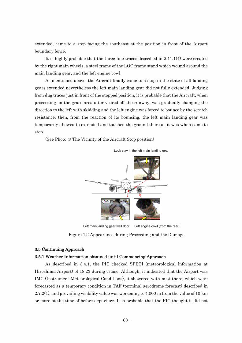
- 63 -
extended, came to a stop facing the southeast at the position in front of the Airport
boundary fence.
It is highly probable that the three line traces described in 2.11.1(4) were created
by the right main wheels, a steel frame of the LOC frame stand which wound around the
main landing gear, and the left engine cowl.
As mentioned above, the Aircraft finally came to a stop in the state of all landing
gears extended nevertheless the left main landing gear did not fully extended. Judging
from dug traces just in front of the stopped position, it is probable that the Aircraft, when
proceeding on the grass area after veered off the runway, was gradually changing the
direction to the left with skidding and the left engine was forced to bounce by the scratch
resistance, then, from the reaction of its bouncing, the left main landing gear was
temporarily allowed to extended and touched the ground there as it was when came to
stop.
(See Photo 4: The Vicinity of the Aircraft Stop position)
Figure 14: Appearance during Proceeding and the Damage
3.5 Continuing Approach
3.5.1 Weather Information obtained until Commencing Approach
As described in 3.4.1, the PIC checked SPECI (meteorological information at
Hiroshima Airport) of 18:23 during cruise. Although, it indicated that the Airport was
IMC (Instrument Meteorological Conditions), it showered with mist there, which were
forecasted as a temporary condition in TAF (terminal aerodrome forecast) described in
2.7.2(1), and prevailing visibility value was worsening to 4,000 m from the value of 10 km
or more at the time of before departure. It is probable that the PIC thought it did not
Lock stay in the left main landing gear
Left main landing gear well door Left engine cowl (from the rear)
- 64 -
affect the landing to the Aircraft. Besides, it is probable that the PIC, during descent or
before commencing an approach, could not recognize fog generation around the Airport
because the FO did not take a note about fog bank in ATIS “T” which he monitored during
descent. As described in 3.4.3, after passing FAF around 20:03, the PIC and the FO
talked that the appearance of the runway was slightly odd. Therefore, it is somewhat
likely that they saw the runway partially covered with fog and were getting to feel
something unusual about the appearance of it.
3.5.2 RVR Notification by Hiroshima Tower
As described in 2.12.1, 2.12.3 and 2.13.3.3, pilots can continue approach when they
could confirm that the meteorological conditions, when they intended to continue
approach beyond the predetermined point (FAF in this case), met the landing minima as
described in 2.13.2.1, while, once after passed the predetermined point, they may
continue approach descent to approach height threshold, even if the meteorological
conditions become worsened to below the landing minima.
As described in 2.1.1, at 20:03:29, Hiroshima Tower reported RVR value of 1,700
m. Checking the records of CVR, it seemed quite normal about the sound volume and
sound quality of the notice reported by Hiroshima Tower; however, the PIC, as described
in 2.1.2(1), did not remember the report of RVR value from Hiroshima Tower. Regarding
the reason that PIC did not remember the report of RVR value from Hiroshima Tower,
it is probable that he did not recognize it because he had already identified the runway,
or he did not take notice of it providing the reported RVR value was not too bad to affect
a safe landing. In addition, it is somewhat likely that the following fact was background
factor; when Hiroshima Tower reported the RVR value the Aircraft had already passed
FAF; irrespective of the reported RVR value, he could continue approach until DA and
should make a decision there whether he could continue approach or not, in accordance
with the rules of the Company.
In addition, the FO did not mention anything about the report of the RVR value
from Hiroshima Tower at all; however, as described in 3.4.3, there was a record of the
sound like "keying" after Hiroshima Tower reported the RVR value. It is somewhat likely
that FO might hear the RVR value from Hiroshima Tower and perform "keying" to send
acknowledge to him.
Around that time, although the FO talked with the PIC that that the appearance
of the runway was slightly odd, it is somewhat likely that he did not take particular care
for the report of the RVR value because he could see the runway on the whole.
- 65 -
3.5.3 Company Minima
As described in 2.1.2(1), it is probable that the PIC believed that the
RNAV(GNSS) approach weather minima applied for himself was the published one in
AIP: approach procedure chart in Appended Figure 7, it means the RVR value of 1,400
m; accordingly, and he considered that the meteorological condition satisfied the weather
minima for commencing RNAV RWY 28 approach. However, as described in 2.13.2.1,
FOM in the Company does not explicitly stipulate the RNAV(GNSS) approach company
weather minima, despite including a general description about non-precision approach.
On that basis, the Company explains about that this RNAV(GNSS) approach company
weather minima is the RVR value of 1,600 m. This means that it is probable that the
PIC had a false recognition of it. It is somewhat likely that the Company does not share
the information among the flight crew members, with respect to having the common
understanding to apply the weather minima which is one of the most important items
for flight operations. It is desirable that the Company properly should organize the rules
and regulations on flight operations, eliminate misunderstandings and consider to take
appropriate measures to promote better understanding for important matters of them.
3.5.4 Requirements for RNAV (GNSS) Approach
As described in 2.12.5, Baro-VNAV Approach Operational Standard stipulates that
pilots must use FD or AP/FD down to DA, and as described in 2.12.6(1), FCOM in the
Company stipulates RNAV(GNSS) approach procedure that if pilots sufficiently identify
visual references at DA, they can continue approach with AP and FD off .
As described in 2.12.1, Ordinance for Enforcement of the Civil Aeronautics Act
stipulates that the aircraft shall follow approach procedures based on the instrumental
flight procedures; the aircraft shall not conduct any other approach than what the
Controller instructed without any instructions or permissions from him or her.
However, the PIC, when the accident occurred, disengaged AP at about 2,100 ft
(HAT about 1,000 ft) then disconnected FD after a second. The FO followed the PIC’s
sequence of operational orders without any objections. Therefore, it is probable that the
PIC and the FO did not understand that pilots must use FD or AP/FD in RNAV (GNSS)
approach until DA. It is probable that the Company shall encourage the flight crew
members to reconfirm that FD or AP/FD must be used until DA when conducting RNAV
(GNSS) approach.
3.5.5 Change to Visual Flying by Hand Maneuver
As shown in Table 3 in 2.7.5, after the Aircraft was passing FAF around 20:03,
- 66 -
only Touchdown RVR values of RWY 28 was getting worse, while Stop-end and Mid-
point RVR continuously maintain the values of “above 1,800 m.” Hiroshima Tower
reported Touchdown RVR of 1,700 m at 20:03:29 and the PIC disengaged AP at 20:03:55.
It is probable that the PIC could confirm the relative position of the Aircraft towards the
runway because it seemed that the PIC and the FO could see an area from center to west
side (RWY 10 side) of the runway despite some difficulties in seeing RWY 28 threshold
just before when the PIC was about to disengage AP/FD.
Besides, it is somewhat likely that although it was occasionally getting difficult
to see RWY 28 threshold due to fog, the PIC was presuming that the weather condition
was not bad to affect the visual flying to maintain an approach path.
From these, it is probable that the PIC changed over to visual flying by hand
maneuver following his usual procedures, as described in 2.1.2(1), of changing to manual
flying from flying with AP/FD when runway in sight.
3.5.6 Need for Go-around
It is probable that while the PIC was assuming that he could make an approach
and maintain the RNAV trajectory in a visual flying manner, as shown in Table 3 in
2.7.5, after disengaging AP at 20:03:55, Touchdown RVR value of RWY 28 was rapidly
getting worse. Around that time, it is probable that fog covered RWY 28 threshold and
the area around the front side of RWY 28, the threshold through the touchdown zone,
including the area where PAPI was placed, was hardly visible for them. As described in
3.4.4, after the Aircraft passed around 1,800 ft (HAT about 700 ft) from 20:04:14 through
20:04:30, the PIC and the FO talked about the runway which looked a bit ambiguous due
to clouds. It is probable that it was difficult to identify visual references continuously to
make a safe landing. While flying visually, it is essential for pilots to continuously
identify visual references required for landing, the PIC should have discontinued an
approach and executed a go-around at this stage.
It is desirable that the Company should surely implement the education and
training of flight crew members to make a right decision of meteorological conditions
while flying visually and execute a go-around immediately after they felt any uncertain
concern for a safe landing.
3.5.7 Rules and Regulations on Continuation of Approach
As described in 2.12.1, Ordinance for Enforcement of the Civil Aeronautics Act
stipulates that when the Instrumental Flight Rules is being used for landing and the
position of the aircraft cannot be confirmed by visual references of landmarks which are
- 67 -
visible and identifiable on a continuing basis at a point below the approach height
threshold, the landing approach shall not be continued. Also, as described in 2.12.2,
Annex 6 to the Convention on International Civil Aviation stipulates that the required
visual reference should have been in view for sufficient time for the pilot to have made
an assessment of the aircraft position and rate of change of positions, in relation to the
desired path. In addition, the same descriptions are found in AIP as described in 2.12.3,
and in POM as described in 2.13.3.4.
As described in 3.4.4, it is probable that there was a possibility that the PIC
possibly could see visual references partially or intermittently below DA. However, it is
probable that he might have been caught in a situation where the position of the aircraft
could not be identified by visual references which should have been in view and identified
continuously at or below DA; therefore, he should have executed a go-around
immediately. In addition, as described later in 3.9.2.3, there might be some cases when
the report of RVR value from the Controller become useful for pilots; however, pilots are
required to make a decision on their own whether continuing descent below DA or
executing a go-around.
As described above, the PIC did not comply with the rules: he continued
approaching below DA even in a situation where the position of the aircraft could not be
identified by visual references which should have been in view and identified
continuously at or below DA. It is probable that there might be a certain background
factor for it that educations and trainings on compliance of the rules were insufficient in
the Company.
It should reemphasize and reinforce crew compliance, while reviewing company
procedures and ensuring comprehensive training.
In addition, as described in 2.17.1(2), the PIC had been generally evaluated "Good"
in the recent proficiency checks or periodic recurrent trainings; however, some relevant
comments on non-compliance of the rules were recorded. It is probable that the Company
had organized a follow-up system and taken proper actions against flight crew members
who had been received a comment. Nevertheless, it is somewhat likely that the follow-
up activities the Company provided for the comments on the PIC were not sufficient. It
is probable that the Company should surely enhance its follow-up systems for flight crew
members who were given comments in the trainings and evaluations, and consider
effective measures in which comments on a certain flight crew member would be properly
addressed and corrected.
- 68 -
3.6 Approach below DA
3.6.1 Approach Primarily Referred to Instruments
As described in 3.4.5, in response to the FO’s concerned word, "Runway not insight,"
the PIC said, "Wait a second" repeatedly and he would not turn down the FO’s word and
mentioned nothing about his recognition of runway. Around 20:04:50, at 1,400 ft (HAT
about 300 ft) the Aircraft was flying into the zone where PAPI, if visible, indicated four
reds (lower path). As shown in Appended Figure 2, however, the descent path angle of
the Aircraft had not been corrected at all until just before the PIC commenced executing
a go-around. Therefore, it is probable that the PIC, as described in 3.5.7, continued
approaching even below DA in a situation where the position of the aircraft could not be
identified by visual references which should have been in view and identified
continuously.
As described in 2.1.2(1), the PIC told as follows: He did never lose sight of runway
even at the final stage of approach. He was making an approach referring to instrument.
He was not conscious that the descent path was getting lower. He decided to execute a
go-around because when he was monitoring instrument he was aware of lateral course
deviation. He was monitoring PAPI and instrument in the ratio of three to seven while
flying below DA.
On the other hand, as described in 2.12.6(2), during RNAV(GNSS) approach,
V/DEV which indicates vertical deviation is not displayed after passing MAPt.
Accordingly, there are no instruments to which a pilot can continuously refer to check
an appropriate approach path below DA (after passing MAPt), but as described in
2.14.2(1), he or she could check the descent path angle and the flying track on the basis
of the aircraft’s position by monitoring "Bird". From these, it is probable that the PIC
was primarily referring to instruments, especially it was somewhat likely that he was
referring to "Bird", while flying below DA.
3.6.2 Significance of Approach Primarily Referred to Visual References
As described in 2.14.2(2), the Manufacturer of the Type states that "Bird" is a
supplementary tool to confirm operational results and even if "Bird" indicates the
descent path angle and the flying track, this does not necessarily mean that the aircraft
is flying on the correct final approach trajectory, and that these are key points when
using "Bird". In other words, the manufacturer does not assume that a pilot might use
"Bird" as if it were a guidance to maintain a descent angle of 3° under the condition of
that he or she cannot see PAPI.
As described in 3.4.4, 3.4.5, in this accident, descent angle of the Aircraft was
- 69 -
gradually getting deeper than the appropriate 3.0° path and its approach path started
deviating from the standard. Without reducing the deviation, its slightly deeper descent
angle was continuously maintained, its vertical deviation did not correct at all.
Consequently it undershot and collided with the LOC frame stand. As described in 3.6.1,
it is somewhat likely that the PIC, in a situation where the position of the aircraft could
not be identified by visual references which should have been in view and identified
continuously, was trying to make an approach primarily referring to instruments,
especially using "Bird" to adjust 3.0° descent angle. However, it is probable that it is
difficult for a pilot to adjust a descent angle of 3.0° with a small reference of "Bird" in
PFD in a precise manner. Therefore, it is somewhat likely that the Aircraft descended
with a slightly deeper descent angle than 3.0° and started deviating from the appropriate
path, then it undershot because it continued approach with the deeper angle.
As described in 2.12.1, 2.12.3 and 2.12.6(1), for a pilot, visual references must be
the primary reference while making an approach below DA in accordance with IFR. It is
probable that the Company should surely implement the education and training that
flight crew members shall fly visually below DA on the basis that visual references must
be the primary reference, using flight instruments as supplementary tools in an
appropriate manner.
3.7 Instruction of Reading the Radio Altimeter
As described in 2.1.2(1) the PIC had landed the Airport three times, and as
described in 2.1.1 during cruise for the Airport, the PIC talked to the FO about the
Airport characteristics of high elevation of the Airport and others. It is probable that he
had understood the topographical aspect around the Airport.
However, as described in 3.4.5, it is probable that the PIC instructed the FO to
check RA (radio altitude) after callout of "Continue." It is probable that this is because
the PIC had been making an approach primarily referring to instruments under the
condition of that position of the Aircraft for runway could not be identified due to fog,
and he temporarily forgot that he was flying over the cliff in front of RWY 28 threshold
and that he presumed that RA could be helpful for referring to the height above the
runway.
As described in 2.13.2.4, FOM stipulates that for non-precision approach, RA shall
not be used because of terrain effect. In addition, it is clear that a pilot should not use of
RA under such a circumstance as shown in Appended Figure1, the final approach course
of RWY 28 passes through the mountains; accordingly, it is not only impractical for a
pilot to assess the tendency of proximity to the ground by checking current and trend of
- 70 -
RA value, but it also might mislead him or her about the height above the runway. It is
probable that the Company shall provide all the flight crew members with educations
once again that they should surely understand rules on flight operations and comply
with them.
3.8 Go-around Call
3.8.1 Situation of the FO
As described in 3.4.4, 3.4.5, the FO called out "Minimum," the PIC responded
"Continue," and the FO concernedly said "Runway not in sight." Afterward, the PIC
repeatedly said "Wait a second" which was not stipulated in SOP; however, the FO did
not make an objection to the PIC. It is somewhat likely that the FO took the PIC’s word
of "Wait a second" as an instruction.
Afterward, the FO was instructed to read out RA and he did not refute and followed
it. When the accident occurred, the PIC was trying to descend below DA while the
position of the aircraft could not be identified by visual references which should have
been in view and identified continuously at or below the approach height threshold (DA).
Under such a circumstances, he normally should have called out "Go-around"
immediately. It is somewhat likely that because he was said "Wait a second" by the PIC,
while being puzzled, he turned his attention to RA following the PIC’s instruction.
3.8.2 Roles of PM
As described in 3.8.1, it is somewhat likely that the cockpit, when the accident
occurred, had an atmosphere in which the FO hesitated to call "Go-around" to the PIC
who was senior and more experienced than him; however, it is probable that even though
he had been instructed "Wait a second" by the PIC, he should have recognized PM’s role
to ensure a safe flight operation, denied the non-compliant operation and called out "Go-
around" immediately, reflecting on the significance of "assertion," which was one of CRM
skills as described in 2.17.2.
3.8.3 Practical Use of CRM Skills
According to the description on CRM HDBK as described in 2.17.2, it emphasizes
that the necessity of "Assertiveness" with the background of a number of instances in
which crew members failed to speak up even when they had critical flight information
that might have averted a disaster, and crew members were often unwilling to state an
opinion or take a course of action even when the operation of the airplane was clearly
outside acceptable parameters. Moreover, it shows some elements of "Assertiveness"
- 71 -
skills as below:
Advocacy: the willingness to state what is believed to be a correct position and to
advocate a course of action consistently and forcefully.
Assertion: stating and maintaining a course of action until convinced otherwise by
further information.
According to the Attachment 2-2: CVR Records, after the PIC commenced an
approach by visual flying, it is probable that the FO was trying to convey his feedbacks
to the PIC over and over again that it was getting difficult for them to identify visual
references and they were making an insecure approach by saying such as "It looks
ambiguous in cloud," "Ah", "What’s the hell." However, he could not make a clear
assertion of concerns on flight safety during the approach. Although he said "Runway
was not in sight" upon descending below DA, the PIC would not express his intension
explicitly and said "Wait a seconds," which led the FO to perceive it as an instruction.
Consequently, the FO had fallen into the situation in which he could not help but follow
the PIC’s instruction.
Besides, according to the description on CRM HDBK as described in 2.17.2,
“Leadership” is a reciprocal process, and requires both leader actions and effective crew
member responses; Effective leaders perform following functions: asking for opinions or
suggestions, reassuring mutual communication, providing feedback towards response
from the follower. When the accident occurred, the FO could not make a clear assertion,
the PIC did not handle the FO’s concerned word properly. Moreover, it is somewhat likely
that the PIC’s leadership was not sufficient while building a good cockpit environment
to promote the FO’s assertion.
As described in 2.17.1, the Company provides the flight crew members with
biannual CRM educations and annual LOFT training and presents implementation of
effective CRM in 5.1.1 (2) "Establish Solid Safety Foundation, " to be described later, as
one of the safety actions. Hereafter, the Company is expected to make every efforts to
enhance CRM skills of all the flight crew members in order that PM could make an
appropriate assertion and they could maintain a good cockpit environment in which
leadership and followership are exerted in a good way.
3.9 Response of ATC Facilities
3.9.1 Selection of Runway in Use
As described in 2.1.1, 2.1.2(1) and 2.7.3, it is highly probable that the PIC and the
FO received ATIS information "T" at around 19:37, which indicated light westerly wind
of 5 kt at the Airport, and recognized RWY 28 was in use instead of RWY 10 in which
- 72 -
precision approach using ILS could be performed. At 19:59:14, the Aircraft was cleared
for RNAV RWY 28 by Hiroshima Radar.
At 20:00:30, the Aircraft established initial communication with Hiroshima Tower
and received a landing clearance with wind information (wind direction 150°, wind speed
4 kt). The FO wondered aloud about RWY 28 landing despite tail wind from the
southeast; however, according to Attachment 2-2: CVR Records, there were no
conversations about the request of runway change in the cockpit. It is somewhat likely
that the PIC and the FO thought that light tail wind had little effect on landing.
As described in 2.7.4, westerly wind for RWY28 had been prevailing since before
the Aircraft commenced an approach (around 19:59) at the Airport, as described in 2.9.1,
traffic flow for RWY 28 operation was continuously established and any runway change
request from it had not been received. In addition, as described in 2.17.4.1, a calm wind
runway is not designated at the Airport. It is highly probable that Hiroshima Tower had
considered these meteorological conditions and aircraft traffic flows and continued RWY
28 operation and his decision did not deviate from the rules of the Standards as described
in 2.17.4.1.
3.9.2 RVR Value Notification
3.9.2.1 Description in the Standards
As described in 2.17.4.2, the Standards stipulates that the RVR value shall be
reported to an arrival aircraft when RVR value has changed from the reported value. In
this case, it shall be reported to the extent which is practicable. On the other hand, as
described in 2.17.5, PANS-ATM stipulates that it shall be done, when changes in
observed RVR value; it does not include any exceptional clause such as "It shall be
reported to the extent which is practicable."
JCAB states about the discrepancy, as described in 2.17.5. It is probable that
because JCAB assumes that there might be some cases in which the Controller might be
unable to inform of every fluctuating RVR value without delay, the Standards stipulates
that the Controller shall report it to the extent feasible.
3.9.2.2 Situation of Hiroshima Tower
As described in Table 3 in 2.7.5, Touchdown RVR was rapidly getting worse after
20:03:15, then Hiroshima Tower reported its RVR value of 1,700 m at 20:03:29. It is
highly probable that, as described in 2.7.5, this report was made in accordance with the
rule because RVR value decreased below 1,800 m. Because Mid-point and Stop-end RVR
value continued to be above 1,800 m around this time, it is somewhat likely that
- 73 -
Hiroshima Tower placed priority on brief notification of a critical information and
reported solely on Touchdown RVR value which was worsening.
However, as described in 2.17.4.2, the Standards stipulates that if any of other RVR
values is 1,800 m or less, all the observed RVR shall be reported. Therefore, it is desirable
that Hiroshima Tower should have reported Mid-point and Stop-end RVR value
following Touchdown RVR value of 1,700 m.
Afterward, Touchdown RVR value continued to decrease, and as described in 2.1.1,
the warning sound to inform the Controller of preparing for Category Ⅲ ILS operation
during ILS RWY10 in use was issued at the Control Tower at 20:04:20. It is probable
that Hiroshima Tower heard it and he was aware of further decreasing RVR value;
however, he did not deliver the second report of the RVR value to the Aircraft which was
close to land. As described in 2.1.2(3), it is somewhat likely that there were following
background factors: Hiroshima Tower presumed that a pilot would execute a go-around
on his or her judgment if he or she noticed unsure conditions during approach such as
the case where runway was not in sight, and he commenced thinking about separation
between the Aircraft and the departure flight while he was prioritizing watching outside.
3.9.2.3 Usefulness of RVR Value Notification
As described in 3.5.2, the RVR value reported by the Controller is necessary
information for a pilot to decide whether commencing a final approach or not at FAF,
however, even after passing FAF (after commencing a final approach), in some cases, it
might become useful information for a pilot to have an image of appearance of visual
references such as runway at DA and recognize the possible go-around.
As described 3.9.2.1, the Standards stipulates that the Controller shall report RVR
values to the extent feasible. Meanwhile, as described in 3.9.2.2, it is somewhat likely
that there were background factors for Hiroshima Tower not to deliver the worsened
RVR value again. Accordingly, it is desirable that Hiroshima Tower should have reported
worsened RVR values to the Aircraft once again, based on the consideration of the
usefulness of reporting RVR value for a pilot in a final approach.
Besides, it is considered necessary that in light of this accident, JCAB should make
a study on the descriptions about RVR report for a pilot in the Standards and its
operating procedures, especially when the RVR value is rapidly decreasing.
3.9.3 Brightness Setting of Aerodrome Lightings
As described in 2.8.1, aerodrome lightings at RWY 28: SALS, REDL, RCCL, RTHL
and PAPI were normally operated to light up in accordance with the specified operational
- 74 -
standards and set the brightness in response to RVR value which Hiroshima Tower
reported.
As described in 3.3, at that timing, RVR value rapidly decreased only in the
touchdown zone, and then Touchdown RVR value recovered in about five minutes from
20:03 to 20:08. Actually, it is not always appropriate for authorities to change the
brightness of aerodrome lightings too frequently in response to RVR values which
fluctuates locally and shortly; therefore, it is highly probable that Hiroshima Tower did
not change the brightness of the lightings.
3.10 Emergency Evacuation
3.10.1 Response by Flight Crew Members
As described in 2.1.2(1), it is probable that the PIC, after complete stop of the
Aircraft, ordered the purser who came into the cockpit to wait and gave priority to
performing EMERGENCY EVACUATION CHECKLIST. It is probable that he noticed
that the emergency evacuation had been initiated in the cabin while performing the
checklist; however, he prioritized carrying out it and it took a longer time to complete.
Therefore, it is probable that when he came out of the cockpit after completing it all the
passengers and FAs in the cabin had already evacuated and he could not play a role as
a PIC that directed and supported emergency evacuation for passengers.
As described in 2.15.1, the PIC and the FO had received emergency evacuation
trainings at the simulator recurrent trainings; however, it is probable that performances
demonstrated by the PIC and the FO at the accident were lacking in readiness. It is
desirable that the Company should review how to handle EMERGENCY EVACUATION
CHECKLIST and re-examine educations and trainings about coordination between
flight crew members and FAs in emergency cases, based on the fact that the PIC who
was the most responsible person for flight operations had not joined the emergency
evacuation in this event.
3.10.2 Actions Taken by FAs
It is probable that the purser was ordered to wait by the PIC, and could not have
talked with FAs in the rear of the cabin due to the failure of interphone systems
described in 3.4.6, and she heard their tense call and confirmed that it seemed smoke
coming up in the rear of the cabin. Therefore, it is probable that she decided that an
emergency evacuation was inevitable and conducted it, in compliance with the rules in
FOM as described in 2.15.3, which enabled the purser to perform emergency evacuation
in case that the flight crew members cannot take appropriate measures even when
- 75 -
emergency situation occurs, that is, she made L1 door open in an urgent manner and
instructed all the passengers to evacuate. In addition, as described in 2.1.2(6), it is
probable that other FAs also instructed passengers to evacuate concurrently followed by
operating main doors and emergency exits for which they are responsible;
consequently, the FAs conducted emergency evacuation procedures in an adequate and
brief manner, in which they could make all the 73 passengers evacuate successfully
under the circumstances that they had no order from the PIC and could not use
interphone and PA systems in the cabin.
As described in 2.11.4, it is probable that all the main doors and three emergency
exits, except the one located right front of center of the cabin, were made open in an
urgent manner, associated evacuation slides were deployed normally and emergency
lightings in the cabin and external emergency lightings for evacuation slides worked
properly.
On the other hand, it is probable that the evacuated passengers commenced
walking to the terminal building respectively, not being gathered together, partly
because FAs were guiding them to step away from the Aircraft. It is somewhat likely
that because the airport RFF personnel and crew members could not make an adequate
coordination each other, to be described later in 3.11(2), both sides accepted those
evacuated passenger’s behavior.
3.10.3 Selection of CAPT and PURS/CAPT Switch
As described in 2.15.4, the type of the Aircraft has equipped with CAPT and
PURS/CAPT Selector Switch for a command of Emergency Evacuation in the cockpit.
Depending on the switch position selected, when emergency evacuation is required, the
emergency evacuation warning signal may either activated only from the cockpit or
both from the cockpit and the cabin. It is supposed to be set in "CAPT" position in POM.
As described in 2.15.3, the Company stipulates in FOM that if flight crew
members do not take appropriate necessary measures in the situation where
emergency evacuation is surely required, the purser shall direct and execute it.
It is desirable that the Company should make a study on selection of the switch:
it might allow to set in "PURS/CAPT" position and provide purser in the cabin for the
additional way of using Evacuation signal to notify emergency evacuation.
3.11 Rescue and Firefighting (RFF)
(1) Notifications to relevant organizations
As described in 2.16.3, the Command desk who received an urgent notification of
- 76 -
the accident occurrence with ”Crash Phone” provided the accident information for the
Operations Center; however, he did not request to dispatch emergency vehicles. In
addition, described in 2.16.2, the Office did not organize "the RFF Corps," which have a
role to support firefighting and medical aid activities. There was no seriously injured
person in this accident; however, triage and ambulance arrangement were delayed.
Consequently, the start of first aid measures for the injured and transportations to
medical institutions of those who treatments were required were considerably delayed.
In addition, the Command desk provided the accident information for several relevant
organizations but he did not inform many other relevant organizations listed in the
System.
It is difficult for administrative office of airports to correctly understand the whole
context of the damage caused by an accident and estimate how wide the damage would
spread immediately after an aircraft accident occurred. If the damage exceeds an
assumption and an emergency notification to relevant organizations and a call for RFF
activities service leaves behind, it would widely spread out. Therefore, a prompt response
is required at the time of the occurrence of the aircraft accident. For this reason, the
Office, in accordance with the described procedure in the Plan, should have sent
emergency notifications, in which calls for service to relevant organizations listed in the
System should be included, and organized the RFF Corps immediately after dispatching
of airport fire engines when the accident occurred.
(2) Escape Guidance after the emergency evacuation
As described in 2.16.2, the airport RFF personnel provided escape guidance for
evacuated passengers; meanwhile, they state that most of evacuated passengers have
started walking toward the International Terminal Building when they arrived at the
site. On the other hand, as described in 2.1.2(5) and (6), the FAs stated that they were
not provided any guidance by the airport RFF personnel. From this, it is somewhat likely
that because the airport RFF personnel and crew members could not make an adequate
coordination; consequently, both sides could not provide guidance for the evacuated
passengers in an appropriate manner.
4. CONCLUSIONS
4.1 Summary of Analysis
(1) The PIC and the FO held both valid airman competence certificates and valid
- 77 -
aviation medical certificates. Besides, the Aircraft had valid airworthiness
certificate and had been maintained and inspected as prescribed. (3.1, 3.2)*75
(2) While the Aircraft making an approach to RWY 28, only Touchdown RVR decreased
rapidly as low as 350 m. After that, the value recovered and returned to the value of
more than 1,800 m. It is probable that the RVR value decreased locally and
transiently because fog flowed into around the touchdown point of RWY 28 from the
south and passed by in approximately five minutes. (3.3)
(3) It is probable that the PIC recognized rain and prevailing visibility of 4,000 m at
the Airport during cruise. He confirmed approach procedure of RNAV RWY 28 while
descending. (3.4.1)
(4) It is somewhat likely that the talk which they made was not appropriate enough to
fulfill the approach briefing stipulated in POM. (3.4.2)
(5) After the PIC and the FO talked that the appearance of the runway was slightly
odd, Hiroshima Tower reported Touchdown RVR of 1,700 m. After that the PIC
disengaged AP and the FO called "FD OFF." It is highly probable that the PIC
changed over to visual flying by hand maneuver at that moment. (3.4.3)
(6) After the FO said, "It looked a bit ambiguous due to clouds," the approach path of
the Aircraft was gradually going lower than standard 3° path. Then, it was flying
into the zone where PAPI indicated one white and three reds if visible (a slightly
lower path than the standard); however, its approach path was not corrected.
Afterward, the FO said, "Getting invisible in a second," the Aircraft passed DA, the
PIC called, "Continue," and continued descending. Immediately after this, the FO
concernedly said, "Runway was not in sight." At this stage, its approach path was
getting even lower but still remained uncorrected. Accordingly, it is probable that
the PIC possibly could see a part of visual references partially or intermittently
below DA, however, he might have been caught in a situation where the position of
the aircraft could not be identified by visual references which should have been in
view and identified continuously at or below DA. In spite of these condition, it is
probable that he continued descending and approaching without executing a go-
*75 The number described in the end of each paragraph starting with (1) and so on in this section corresponds with
the section in the Chapter 3. ANALYSIS.
- 78 -
around. (3.4.4)
(7) When the FO concernedly said, ”Runway was not in sight,” in response, the PIC
said, ”Wait a second,” then the Aircraft was flying into the zone where PAPI
indicated four reds if visible (a lower path than the standard) the PIC instructed the
FO to check radio altitude carefully. Afterward, an Auto RA call of "300 ft" and "200
ft" announced in a short interval, then, the PIC called out for executing a go-around,
and commenced raising the nose. Accordingly, the pitch angle of the Aircraft was
just about to increase; however, immediately after that, the Aircraft collided with
the LOC frame stand. (3.4.5)
(8) It is highly probable that the Aircraft collided with the central parts of the LOC
frame stand 6 m high with the both engines, the both main landing gears, the flaps,
the lower surface of fuselage and the horizontal stabilizers. Having collided with the
LOC frame stand, it is probable that the Aircraft badly damaged lights of SALS and
touched down on the grass area at the east of RWY 28 threshold with the fuselage
tail, then right and left main wheels followed. (3.4.6)
(9) The Aircraft smashed down ORL lights and proceeded on the runway. Aircraft
became less able to hold the left main landing gear extended due to impact of the
collision, the left engine cowl became to touch on the runway surface; accordingly, it
gradually veered off the runway to the left (the south) as proceeding forward. The
Aircraft, with all landing gears extended, finally came to a stop facing the southeast
at the position in front of the Airport boundary fence. (3.4.7)
(10) It is probable that the PIC, during descent or before commencing an approach,
could not recognize fog generation around the Airport. After passing FAF, the PIC
and the FO talked that the appearance of the runway was slightly odd. Therefore, it
is somewhat likely that they saw the runway partially covered with fog and were
getting to feel something unusual about the appearance of it. (3.5.1)
(11) The PIC stated that he did not remember the report of RVR value of 1,700 m from
Hiroshima Tower. It is somewhat likely that the FO did not take particular care for
the report of the RVR value because he could identify the runway on the whole.
(3.5.2)
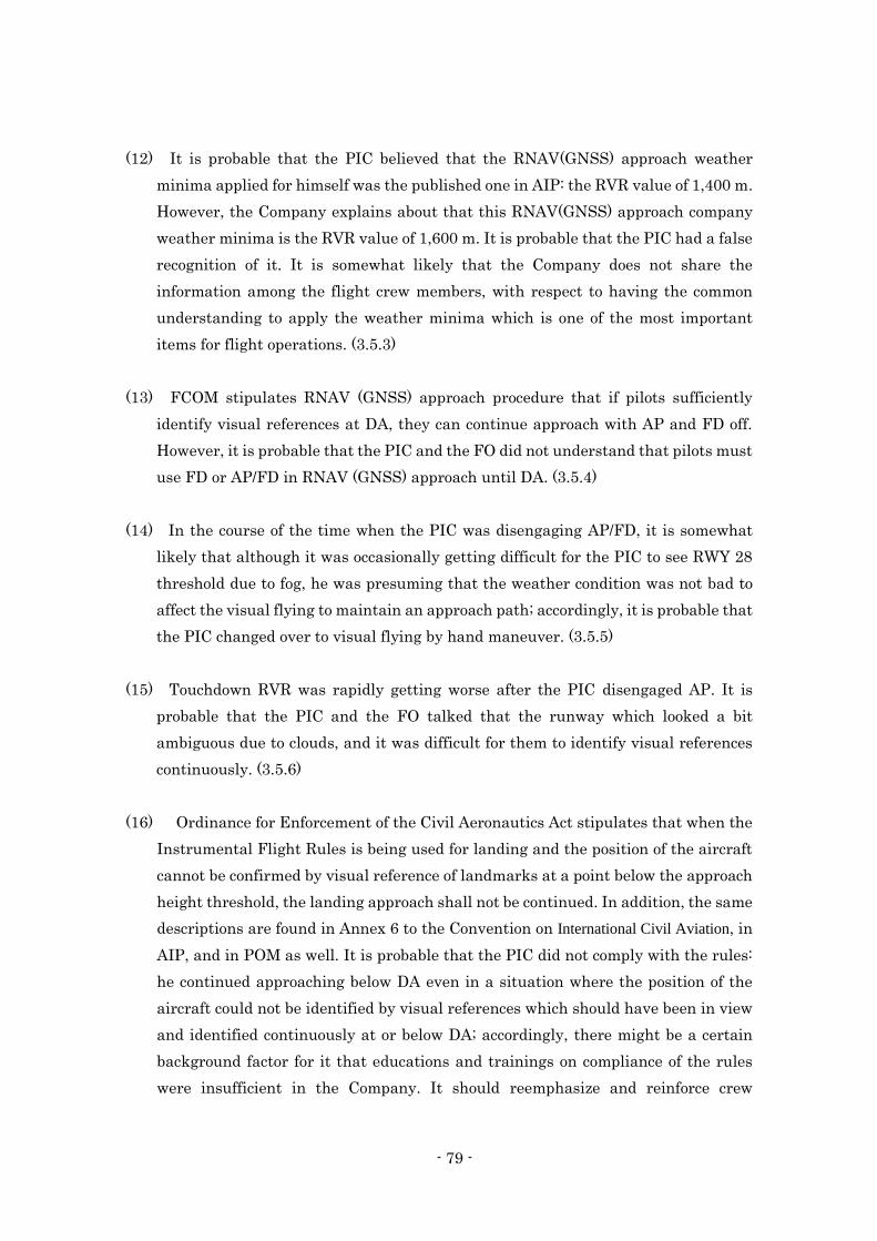
- 79 -
(12) It is probable that the PIC believed that the RNAV(GNSS) approach weather
minima applied for himself was the published one in AIP: the RVR value of 1,400 m.
However, the Company explains about that this RNAV(GNSS) approach company
weather minima is the RVR value of 1,600 m. It is probable that the PIC had a false
recognition of it. It is somewhat likely that the Company does not share the
information among the flight crew members, with respect to having the common
understanding to apply the weather minima which is one of the most important
items for flight operations. (3.5.3)
(13) FCOM stipulates RNAV (GNSS) approach procedure that if pilots sufficiently
identify visual references at DA, they can continue approach with AP and FD off.
However, it is probable that the PIC and the FO did not understand that pilots must
use FD or AP/FD in RNAV (GNSS) approach until DA. (3.5.4)
(14) In the course of the time when the PIC was disengaging AP/FD, it is somewhat
likely that although it was occasionally getting difficult for the PIC to see RWY 28
threshold due to fog, he was presuming that the weather condition was not bad to
affect the visual flying to maintain an approach path; accordingly, it is probable that
the PIC changed over to visual flying by hand maneuver. (3.5.5)
(15) Touchdown RVR was rapidly getting worse after the PIC disengaged AP. It is
probable that the PIC and the FO talked that the runway which looked a bit
ambiguous due to clouds, and it was difficult for them to identify visual references
continuously. (3.5.6)
(16) Ordinance for Enforcement of the Civil Aeronautics Act stipulates that when the
Instrumental Flight Rules is being used for landing and the position of the aircraft
cannot be confirmed by visual reference of landmarks at a point below the approach
height threshold, the landing approach shall not be continued. In addition, the same
descriptions are found in Annex 6 to the Convention on International Civil Aviation, in
AIP, and in POM as well. It is probable that the PIC did not comply with the rules:
he continued approaching below DA even in a situation where the position of the
aircraft could not be identified by visual references which should have been in view
and identified continuously at or below DA; accordingly, there might be a certain
background factor for it that educations and trainings on compliance of the rules
were insufficient in the Company. It should reemphasize and reinforce crew
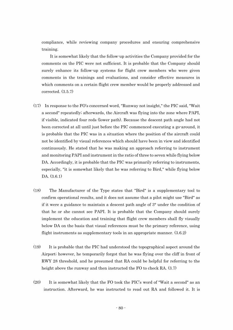
- 80 -
compliance, while reviewing company procedures and ensuring comprehensive
training.
It is somewhat likely that the follow-up activities the Company provided for the
comments on the PIC were not sufficient. It is probable that the Company should
surely enhance its follow-up systems for flight crew members who were given
comments in the trainings and evaluations, and consider effective measures in
which comments on a certain flight crew member would be properly addressed and
corrected. (3.5.7)
(17) In response to the FO’s concerned word, "Runway not insight," the PIC said, "Wait
a second" repeatedly; afterwards, the Aircraft was flying into the zone where PAPI,
if visible, indicated four reds (lower path). Because the descent path angle had not
been corrected at all until just before the PIC commenced executing a go-around, it
is probable that the PIC was in a situation where the position of the aircraft could
not be identified by visual references which should have been in view and identified
continuously. He stated that he was making an approach referring to instrument
and monitoring PAPI and instrument in the ratio of three to seven while flying below
DA. Accordingly, it is probable that the PIC was primarily referring to instruments,
especially, "it is somewhat likely that he was referring to Bird," while flying below
DA. (3.6.1)
(18) The Manufacturer of the Type states that "Bird" is a supplementary tool to
confirm operational results, and it does not assume that a pilot might use "Bird" as
if it were a guidance to maintain a descent path angle of 3° under the condition of
that he or she cannot see PAPI. It is probable that the Company should surely
implement the education and training that flight crew members shall fly visually
below DA on the basis that visual references must be the primary reference, using
flight instruments as supplementary tools in an appropriate manner. (3.6.2)
(19) It is probable that the PIC had understood the topographical aspect around the
Airport; however, he temporarily forgot that he was flying over the cliff in front of
RWY 28 threshold, and he presumed that RA could be helpful for referring to the
height above the runway and then instructed the FO to check RA. (3.7)
(20) It is somewhat likely that the FO took the PIC’s word of "Wait a second" as an
instruction. Afterward, he was instructed to read out RA and followed it. It is
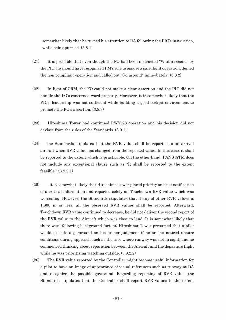
- 81 -
somewhat likely that he turned his attention to RA following the PIC’s instruction,
while being puzzled. (3.8.1)
(21) It is probable that even though the FO had been instructed "Wait a second" by
the PIC, he should have recognized PM’s role to ensure a safe flight operation, denied
the non-compliant operation and called out "Go-around" immediately. (3.8.2)
(22) In light of CRM, the FO could not make a clear assertion and the PIC did not
handle the FO’s concerned word properly. Moreover, it is somewhat likely that the
PIC’s leadership was not sufficient while building a good cockpit environment to
promote the FO’s assertion. (3.8.3)
(23) Hiroshima Tower had continued RWY 28 operation and his decision did not
deviate from the rules of the Standards. (3.9.1)
(24) The Standards stipulates that the RVR value shall be reported to an arrival
aircraft when RVR value has changed from the reported value. In this case, it shall
be reported to the extent which is practicable. On the other hand, PANS-ATM does
not include any exceptional clause such as "It shall be reported to the extent
feasible." (3.9.2.1)
(25) It is somewhat likely that Hiroshima Tower placed priority on brief notification
of a critical information and reported solely on Touchdown RVR value which was
worsening. However, the Standards stipulates that if any of other RVR values is
1,800 m or less, all the observed RVR values shall be reported. Afterward,
Touchdown RVR value continued to decrease, he did not deliver the second report of
the RVR value to the Aircraft which was close to land. It is somewhat likely that
there were following background factors: Hiroshima Tower presumed that a pilot
would execute a go-around on his or her judgment if he or she noticed unsure
conditions during approach such as the case where runway was not in sight, and he
commenced thinking about separation between the Aircraft and the departure flight
while he was prioritizing watching outside. (3.9.2.2)
(26) The RVR value reported by the Controller might become useful information for
a pilot to have an image of appearance of visual references such as runway at DA
and recognize the possible go-around. Regarding reporting of RVR value, the
Standards stipulates that the Controller shall report RVR values to the extent
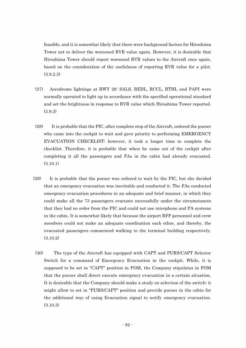
- 82 -
feasible, and it is somewhat likely that there were background factors for Hiroshima
Tower not to deliver the worsened RVR value again. However, it is desirable that
Hiroshima Tower should report worsened RVR values to the Aircraft once again,
based on the consideration of the usefulness of reporting RVR value for a pilot.
(3.9.2.3)
(27) Aerodrome lightings at RWY 28: SALS, REDL, RCCL, RTHL and PAPI were
normally operated to light up in accordance with the specified operational standard
and set the brightness in response to RVR value which Hiroshima Tower reported.
(3.9.3)
(28) It is probable that the PIC, after complete stop of the Aircraft, ordered the purser
who came into the cockpit to wait and gave priority to performing EMERGENCY
EVACUATION CHECKLIST; however, it took a longer time to complete the
checklist. Therefore, it is probable that when he came out of the cockpit after
completing it all the passengers and FAs in the cabin had already evacuated.
(3.10.1)
(29) It is probable that the purser was ordered to wait by the PIC, but she decided
that an emergency evacuation was inevitable and conducted it. The FAs conducted
emergency evacuation procedures in an adequate and brief manner, in which they
could make all the 73 passengers evacuate successfully under the circumstances
that they had no order from the PIC and could not use interphone and PA systems
in the cabin. It is somewhat likely that because the airport RFF personnel and crew
members could not make an adequate coordination each other, and thereby, the
evacuated passengers commenced walking to the terminal building respectively.
(3.10.2)
(30) The type of the Aircraft has equipped with CAPT and PURS/CAPT Selector
Switch for a command of Emergency Evacuation in the cockpit. While, it is
supposed to be set in "CAPT" position in POM, the Company stipulates in FOM
that the purser shall direct execute emergency evacuation in a certain situation.
It is desirable that the Company should make a study on selection of the switch: it
might allow to set in "PURS/CAPT" position and provide purser in the cabin for
the additional way of using Evacuation signal to notify emergency evacuation.
(3.10.3)
- 83 -
(31) The Office, in accordance with the described procedure in the Plan, should have
sent emergency notifications, in which calls for service to relevant organizations
listed in the System should be included, and organized the RFF Corps. It is
somewhat likely that because the airport RFF personnel and crew members could
not make an adequate coordination; consequently, both sides could not provide
guidance for the evacuated passengers in an appropriate manner. (3.11)
4.2 Probable Causes
It is certain that when landing on RWY 28 at the Airport, the Aircraft undershot
and the PIC commenced executing a go-around; however, it collided with the
Aeronautical Radio Navigation Aids located in front of RWY 28 threshold, just before
turning to climb.
Regarding the fact that the Aircraft undershot, it is probable that there might be
following aspects in causes: The PIC continued approaching without executing a go-
around while the position of the Aircraft could not be identified by visual references
which should have been in view and identified continuously at or below the approach
height threshold (Decision Altitude: DA); and as well, the FO, as pilot-monitoring who
should have monitored meteorological conditions and flight operations, did not make a
call-out of go-around immediately when he could not see the runway at DA.
Regarding the fact that the PIC continued approaching without executing a go-
around while the position of the Aircraft could not be identified by visual references
which should have been in view and identified continuously at or below DA, he did not
comply with the regulations and SOP, and it is probable that there was a background
factor that the education and trainings for compliance of rules in the Company was
insufficient. In addition, regarding the fact that the FO did not make an assertion of go-
around, it is probable that the CRM did not function appropriately.
5. SAFETY ACTIONS
5.1 Safety Actions Taken
5.1.1 Actions Taken by the Company
The Company has taken the following safety actions to prevent recurrence in
response to Notice of Improvement and Recommendations*76 given from Korea Office of
*76 Korea Office of Civil Aviation, Ministry of Land Infrastructure and Transport submitted the Company nine
Notice of Improvement and five Recommendations in June 12, 2015.
- 84 -
Civil Aviation, Ministry of Land Infrastructure and Transport as below.
(1) Safety Actions Taken after the accident occurred
1. The Company held face-to-face briefing education session about the importance
of safe flight.
2. It implemented special simulator trainings for flight crew members such as
improvement of visual approach skill, situation-awareness skill under the low
visibility condition, and situation management skill in a non-precision approach.
3. It provided educations for flight crew members such as compliance to conditions
for a stabilized approach, surely encouraging PM’s duty to monitor deviation of
aircraft and go-around calls and PF’s response in a timely and appropriate manner.
Moreover, as CRM related matters, it instructed the importance of information
sharing between PF and PM about a visual approach in an approach briefing.
4. It revised in-house airport information about Hiroshima airport.
5. It unified standard callouts of each aircraft type.
6. It upgraded several functions of simulator of the Type.
7. It established "Monthly check analysis meeting" to analyze the result of
recurrent checks (both in simulator and in route) of flight crew and seek out
"Monitoring required flight crew" who have shown deficiencies on flight skills or
procedure adherence and arrange them to go through random or other checks.
(2) Plans to be taken to establish solid safety foundation
1. The Company presses forward with establishment of integrated safety
information management system.
2. It implements effective CRM to improve competency of flight crew members.
3. It establishes afresh Safety Investigation Division in Safety and Security
department and Flight Crew Training Division becomes independent from
Flight Operation Headquarters.
4. It reviews following matters to establish a safety culture in the Company; it
establishes FOQA*77 committee and enables to utilize FOQA data in reference to
each flight crew member, it promotes penalty free reporting system, it conducts
safety survey of the Company structure by external organization and reviews
countermeasures against its result, and it establishes Safety Education Center
(tentative title).
*77 "FOQA" stands for Flight Operational Quality Assurance. It is a program to take countermeasures by analyzing
flight data in daily flight operation and finding possibilities of unsafe elements that might lead accidents in order to
prevent accident before they occur.
- 85 -
5.1.2 Actions Taken by JCAB
(1) Related matters in ATC
On the basis of consideration that reporting of RVR value is useful for a pilot
when RVR value is rapidly changing, JCAB has been having an exchange of views
over "useful RVR value for the operator" with airline companies in Japan. Moreover,
it has been proceeding examination for the measures including the revision of rules
and regulations relevant to reporting of RVR value.
(2) Related matters in RFF
JCAB decided to implement following measures to ensure RFF services to be
conducted appropriately in case of an emergency.
1. In order that personnel in charge can deliver urgent message including
requests for emergency dispatch to relevant organizations in the System and
organize the RFF Corps in a prompt and appropriate manner, JCAB has
undertaken revision works of "Standards for Establishment of RFF System in
Airport" as a national standard for RFF services and "Ⅲ Fire-fighting and
Rescue Services Rules in the Air Navigation Services Handbook"
2. In order that involved parties and personnel in RFF organizations can take
initial actions in a prompt and appropriate manner; they shall recognize the
emergency, assess the situation, request emergency dispatch for sure as well as
place an urgent call to staff members in the facility to readily establish the
framework to deploy, JCAB decided to provide practical education and training
with them at the Education and Training Center for Airport Security and
Disaster Prevention*78, in parallel with keeping personnel informed about the
significance of actions to be taken as well as the actions themselves at the
occasion such as "The manager meeting over the airport security and disaster
prevention."
JCAB decided to implement practical training such as receiving and
recording information on an emergency, giving an instruction for dispatch, and
requesting involved personnel in the Office and relevant organizations to deploy,
realized that services the Command desk provides was one of the important
works when proceeding RFF activities.
*78 "The Education and Training Center for Airport Security and Disaster Prevention" is the national facility where government
service personnel involved in the aviation security and nationwide personnel in the airports involved in disaster prevention and RFF are educated and trained.
- 86 -
5.1.3 Actions Taken by the Office
After the accident, the Office implemented a full-scale emergency exercise to
prepare for aircraft accident from 13:00 to 15:00 on November 25, 2015, in which
308 people from 49 organizations including the Office, the fire department, Police,
Japan Coast Guard and Hiroshima Prefectural office participated in.
5.2 Safety Actions Required
As described in 5.1.1, the Company has taken actions such as surely
encouraging PM’s go-around call and PF’s response in a timely and appropriate
manner. It decides to implement a measure that it examines comments which flight
crew members received in the training and the proficiency check, identifies a specific
flight crew member to be monitored, and takes a necessary action for him or her.
However, reviewing flight operations in the accident, there were several non-
compliance with regulations and SOP, for example, flying without referring to FD
or AP/FD during RNAV(GNSS) approach, using RA inappropriately which was
brought by insufficient understanding of regulations.
The Company, taking into account the lessons learned from the accident,
should reemphasize and reinforce crew compliance, while reviewing company
procedures and ensuring comprehensive training.
In addition, it should surely implement the education and training that flight
crew members shall fly visually below DA on the basis that visual references must
be the primary reference, using flight instruments as supplementary tools in an
appropriate manner.
6. SAFETY RECOMMENDATIONS
It is certain that when landing on runway 28 at Hiroshima airport, the aircraft
undershot and the Pilot-in-Command (PIC) commenced executing a go-around; however,
it collided with the Aeronautical Radio Navigation Aids located in front of runway 28
threshold, just before turning to climb.
In this accident, the PIC did not comply with the regulations and Standard
Operating Procedures (SOP): He continued approaching below the approach height
threshold (Decision Altitude: DA) without executing a go-around in a situation while the
position of the aircraft could not be identified by visual references which should have
been in view and identified continuously at or below DA. Other than that, there were
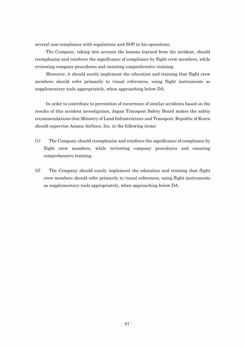
- 87 -
several non-compliance with regulations and SOP in his operations.
The Company, taking into account the lessons learned from the accident, should
reemphasize and reinforce the significance of compliance by flight crew members, while
reviewing company procedures and ensuring comprehensive training.
Moreover, it should surely implement the education and training that flight crew
members should refer primarily to visual references, using flight instruments as
supplementary tools appropriately, when approaching below DA.
In order to contribute to prevention of recurrence of similar accidents based on the
results of this accident investigation, Japan Transport Safety Board makes the safety
recommendations that Ministry of Land Infrastructure and Transport, Republic of Korea
should supervise Asiana Airlines, Inc. in the following items:
(1) The Company should reemphasize and reinforce the significance of compliance by
flight crew members, while reviewing company procedures and ensuring
comprehensive training.
(2) The Company should surely implement the education and training that flight
crew members should refer primarily to visual references, using flight instruments
as supplementary tools appropriately, when approaching below DA.
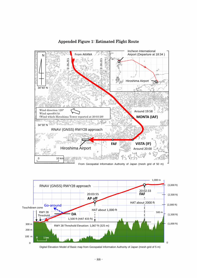
- 88 -
Appended Figure 1: Estimated Flight Route
FAF VISTA (IF)
MONTA (IAF)
Hiroshima Airport
34°40′ N
From Geospatial Information Authority of Japan (mesh grid of 50 m)
Around 19:58
Around 20:00
34°30′ N
N
RNAV (GNSS) RWY28 approach 132°5
0’ E
133°0
0’ E
Incheon International Airport (Departure at 18:34 )
Hiroshima Airport
10 km 0
From AKANA
Wind direction 120° Wind speed04 kt (Wind which Hiroshima Tower reported at 20:03:29)
1 km 0
Digital Elevation Model of Basic map from Geospatial Information Authority of Japan (mesh grid of 5 m)
20:03:55 AP off
RWY 28 Threshold
Touchdown zone
RNAV (GNSS) RWY28 approach
200 m
0
300 m
100 m
DA 1,500 ft (HAT 433 ft)
RWY 28 Threshold Elevation: 1,067 ft (325 m)
HAT about 1,000 ft
HAT about 2000 ft Go-around
(1,000 ft)
(2,000 ft)
(3,000 ft)
(1,500 ft)
(2,500 ft)
1,000 m
500 m
0
N
20:02:33 FAF
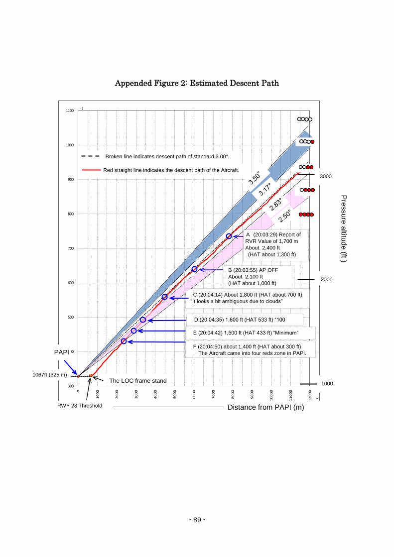
- 89 -
Appended Figure 2: Estimated Descent Path
300
400
500
600
700
800
900
1000
1100
0
10
00
20
00
30
00
40
00
50
00
60
00
70
00
80
00
90
00
10
00
0
11
00
0
12
00
0
RWY 28 Threshold
THR Elevation
(
(
PAPI
B (20:03:55) AP OFF
About. 2,100 ft
(HAT about 1,000 ft)
Distance from PAPI (m)
3000
2000
1000
Pre
ssure
altitu
de (ft )
E (20:04:42) 1,500 ft (HAT 433 ft) “Minimum“
D (20:04:35) 1,600 ft (HAT 533 ft) “100
above”
F (20:04:50) about 1,400 ft (HAT about 300 ft)
The Aircraft came into four reds zone in PAPI.
C (20:04:14) About 1,800 ft (HAT about 700 ft) “It looks a bit ambiguous due to clouds”
The LOC frame stand
Red straight line indicates the descent path of the Aircraft.
Broken line indicates descent path of standard 3.00°.
A (20:03:29) Report of
RVR Value of 1,700 m
About. 2,400 ft
(HAT about 1,300 ft)
1067ft (325 m)
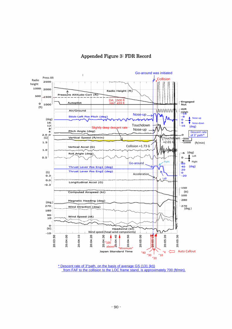
- 90 -
Appended Figure 3: FDR Record
Collision
Go-around was initiated Press Alt
(G)
(G)
Acceleration
Go-around
Nose-up
Nose-up Slightly deep descent rate
(ft/min)
(deg.)
(deg)
(deg)
(deg)
(deg.)
(kt)
(kt)
(deg) Nose-up
Nose-down
Left
Descent rate of 3° path* path
Collision +1.73 G
Left
Radio height
DA: 1500 ft HAT 433 ft
“Minimum” “40
“30“20
“10“4
“100 above”
Auto Callout
Wind speed (head wind components)
Touchdown
Touchdown +2.01 G
* Descent rate of 3°path, on the basis of average GS (131 (kt)) from FAF to the collision to the LOC frame stand, is approximately 700 (ft/min).
Right Right
(ft)
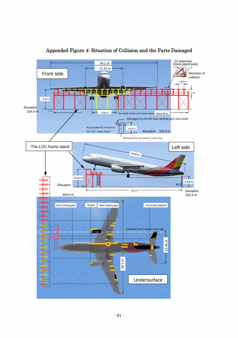
- 91 -
Appended Figure 4: Situation of Collision and the Parts Damaged
下面
Left side
Front
The LOC frame stand
Damaged by the left main landing gear (one bulb)
G.L.
G.L. Elevation 323.9 m
6.44 m
ALS located 35 m short of the LOC frame stand
The width of the LOC frame stand : about 40 m
11.51 m 34.1 m
7.59 m
1.63 m
2 m
Extended line of runway center line
24 antennas (steel-piped pole)
Direction of collision
Elevation
324.0 m
4.04 m
G.L.
6.44 m
35 m
4.04 m
Elevation
323.9 m
ALS
Nose landing gear Engine Main landing gear Horizontal stabilizer
Extended line of runway center line
34.1
m
12.4
5 m
Front side
Left side
Undersurface
Elevation
324.0 m
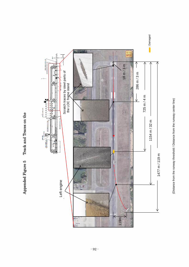
- 92 -
Ap
pen
ded
Fig
ure
5 T
rack
an
d T
race
s on
th
e
Ru
nw
ay
11
54
m / 3
2 m
72
5 m
/ 4
m
28
6 m
/ 3
m
Left
eng
ine
tra
ce
14
77
m / 1
19
m
Scra
tch tra
ces b
y s
tee
l part
s o
f th
e L
OC
fra
me s
tand
11
9
(Dis
tance
fro
m t
he
ru
nw
ay t
hre
sh
old
/ D
ista
nce
fro
m t
he
ru
nw
ay c
en
ter
line
)
: D
am
aged
18
m / 3
m
11
9m
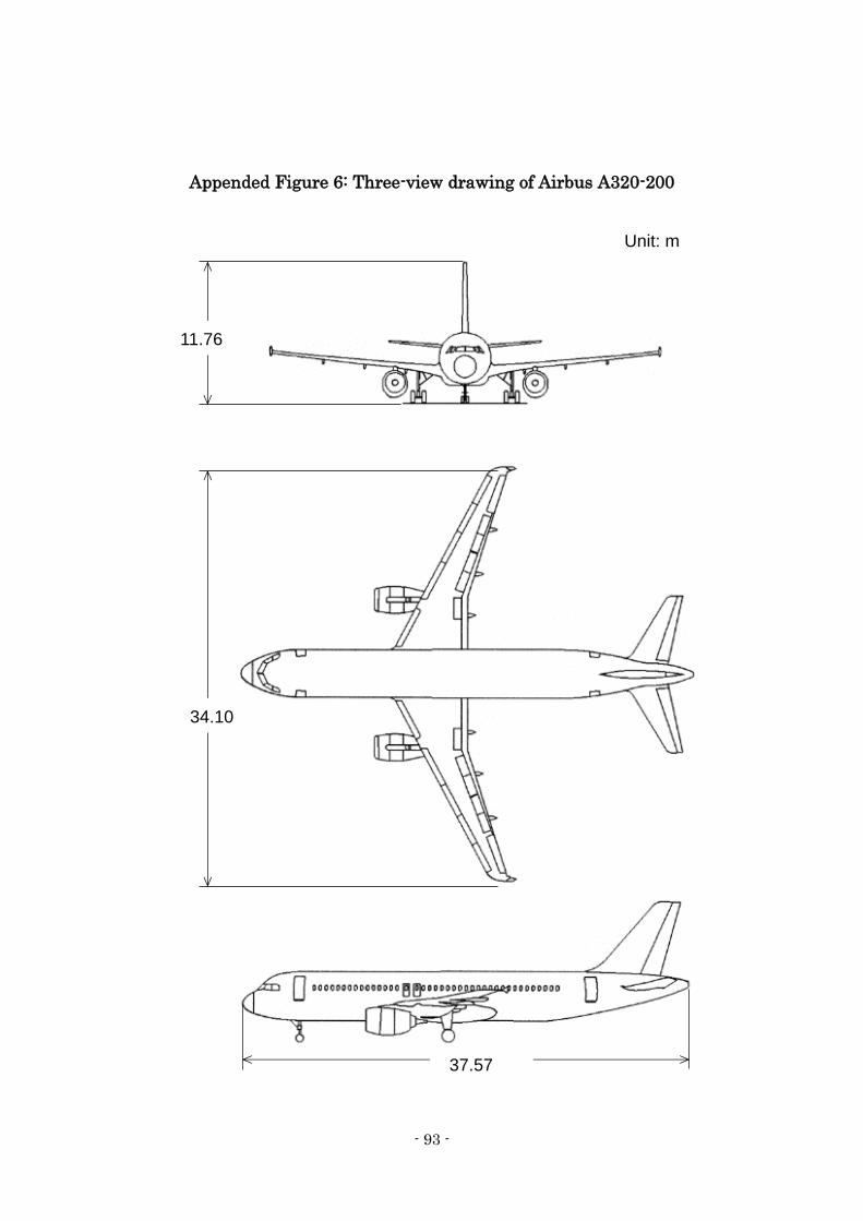
- 93 -
Appended Figure 6: Three-view drawing of Airbus A320-200
11.76
34.10
37.57
Unit: m
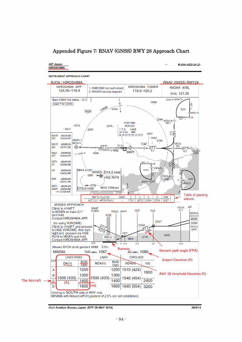
- 94 -
Appended Figure 7: RNAV (GNSS) RWY 28 Approach Chart
The Aircraft
Descent path angle (FPA)
RWY 28 threshold Elevation (ft)
Runway
Airport Elevation (ft)
(ft)
(m)
Table of passing
altitude
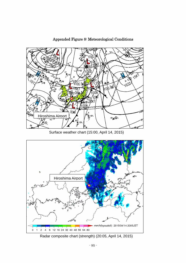
- 95 -
Appended Figure 8: Meteorological Conditions
Surface weather chart (15:00, April 14, 2015)
Radar composite chart (strength) (20:05, April 14, 2015)
Hiroshima Airport
Hiroshima Airport
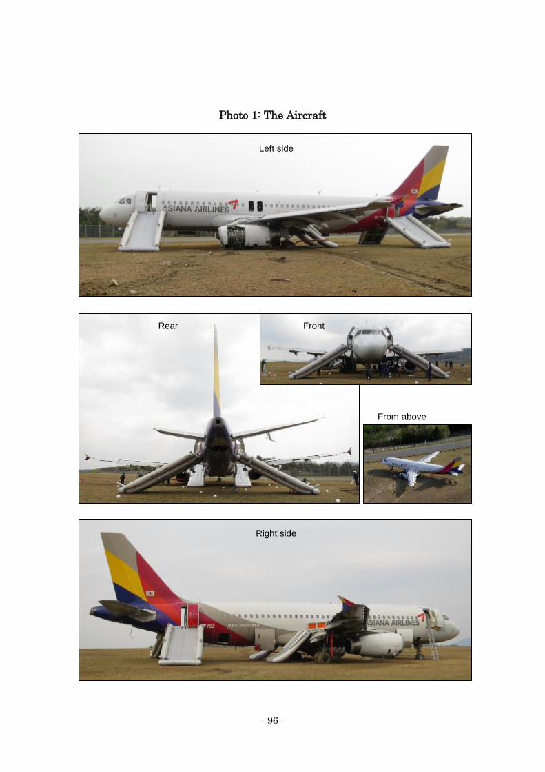
- 96 -
Photo 1: The Aircraft
Left side
Front Rear
Right side
From above
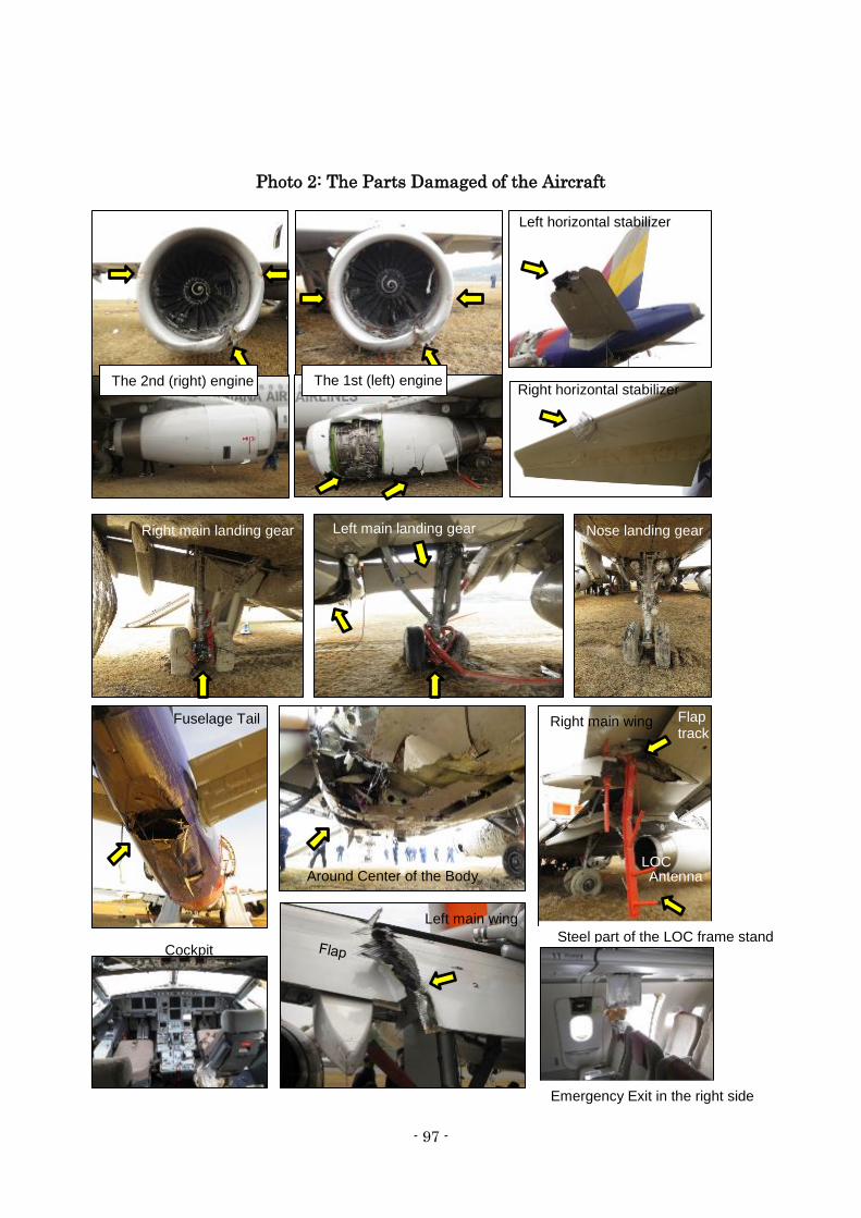
- 97 -
Photo 2: The Parts Damaged of the Aircraft
Left horizontal stabilizer
Right horizontal stabilizer
Nose landing gear Right main landing gear Left main landing gear
Fuselage Tail Right main wing
Around Center of the Body
Left main wing
Cockpit
Emergency Exit in the right side
The 2nd (right) engine The 1st (left) engine
Flap track
Steel part of the LOC frame stand
LOC Antenna
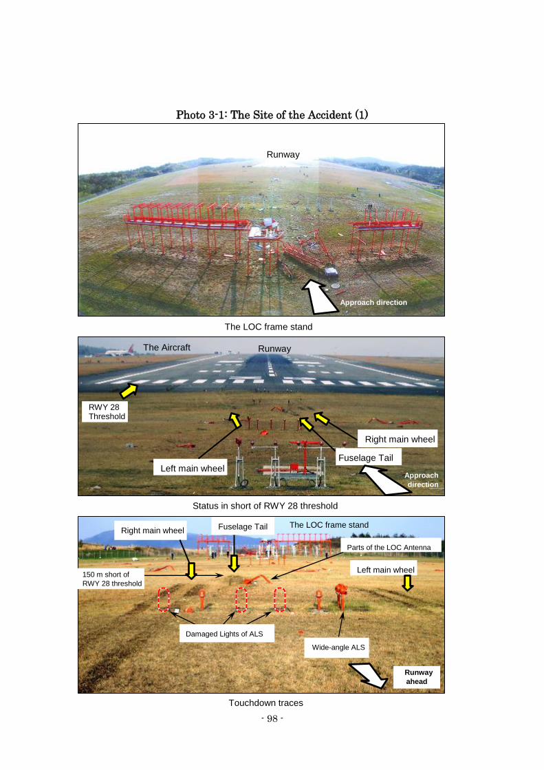
- 98 -
Photo 3-1: The Site of the Accident (1)
Left main wheel
Fuselage Tail
Runway
ahead
Left main wheel
Right main wheel
Fuselage Tail
The Aircraft
Touchdown traces
Status in short of RWY 28 threshold
The LOC frame stand
RWY 28 Threshold
Runway
Runway
The LOC frame stand
Approach direction
Approach direction
Damaged Lights of ALS Wide-angle ALS
150 m short of RWY 28 threshold
Right main wheel
Parts of the LOC Antenna
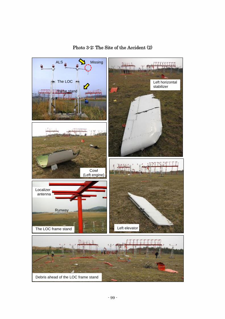
- 99 -
Photo 3-2: The Site of the Accident (2)
Missing
Cowl (Left engine)
ALS
Left horizontal stabilizer
Left elevator
Debris ahead of the LOC frame stand
Localizer antenna
The LOC
frame stand
Runway
The LOC frame stand
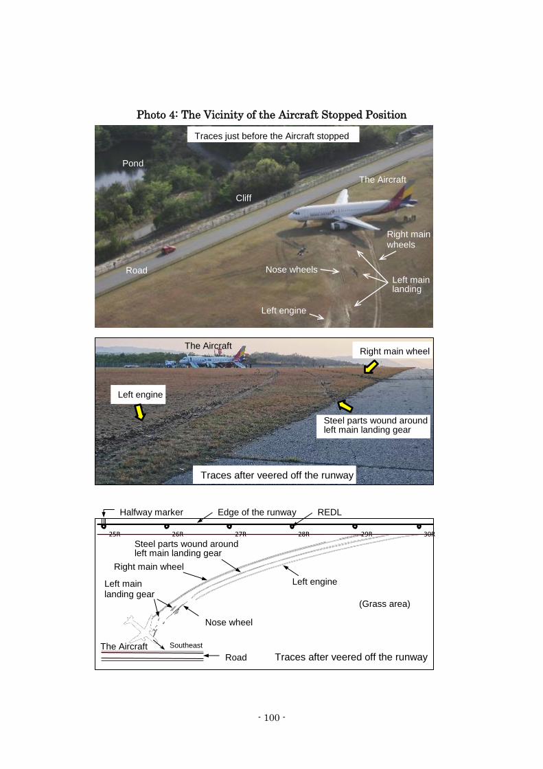
- 100 -
Photo 4: The Vicinity of the Aircraft Stopped Position
Right main wheel
Steel parts wound around left main landing gear
Left engine
Right main wheels
Nose wheels Left main landing
Left engine
Traces just before the Aircraft stopped
Traces after veered off the runway
Right main wheel
Left main landing gear
Nose wheel
Left engine
Cliff
Pond
The Aircraft
The Aircraft
The Aircraft
30R 29R 28R 27R 26R 25R
Southeast Road
Halfway marker Edge of the runway REDL
(Grass area)
Steel parts wound around left main landing gear
Road
Traces after veered off the runway
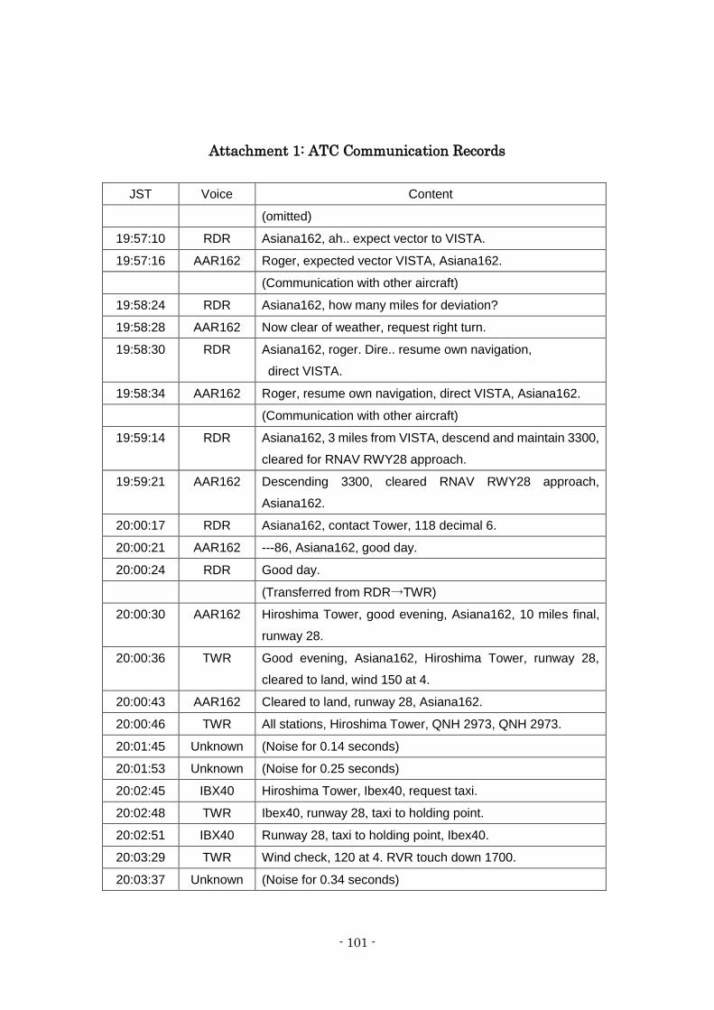
- 101 -
Attachment 1: ATC Communication Records
JST Voice Content
(omitted)
19:57:10 RDR Asiana162, ah.. expect vector to VISTA.
19:57:16 AAR162 Roger, expected vector VISTA, Asiana162.
(Communication with other aircraft)
19:58:24 RDR Asiana162, how many miles for deviation?
19:58:28 AAR162 Now clear of weather, request right turn.
19:58:30 RDR Asiana162, roger. Dire.. resume own navigation,
direct VISTA.
19:58:34 AAR162 Roger, resume own navigation, direct VISTA, Asiana162.
(Communication with other aircraft)
19:59:14 RDR Asiana162, 3 miles from VISTA, descend and maintain 3300,
cleared for RNAV RWY28 approach.
19:59:21 AAR162 Descending 3300, cleared RNAV RWY28 approach,
Asiana162.
20:00:17 RDR Asiana162, contact Tower, 118 decimal 6.
20:00:21 AAR162 ---86, Asiana162, good day.
20:00:24 RDR Good day.
(Transferred from RDR→TWR)
20:00:30 AAR162 Hiroshima Tower, good evening, Asiana162, 10 miles final,
runway 28.
20:00:36 TWR Good evening, Asiana162, Hiroshima Tower, runway 28,
cleared to land, wind 150 at 4.
20:00:43 AAR162 Cleared to land, runway 28, Asiana162.
20:00:46 TWR All stations, Hiroshima Tower, QNH 2973, QNH 2973.
20:01:45 Unknown (Noise for 0.14 seconds)
20:01:53 Unknown (Noise for 0.25 seconds)
20:02:45 IBX40 Hiroshima Tower, Ibex40, request taxi.
20:02:48 TWR Ibex40, runway 28, taxi to holding point.
20:02:51 IBX40 Runway 28, taxi to holding point, Ibex40.
20:03:29 TWR Wind check, 120 at 4. RVR touch down 1700.
20:03:37 Unknown (Noise for 0.34 seconds)
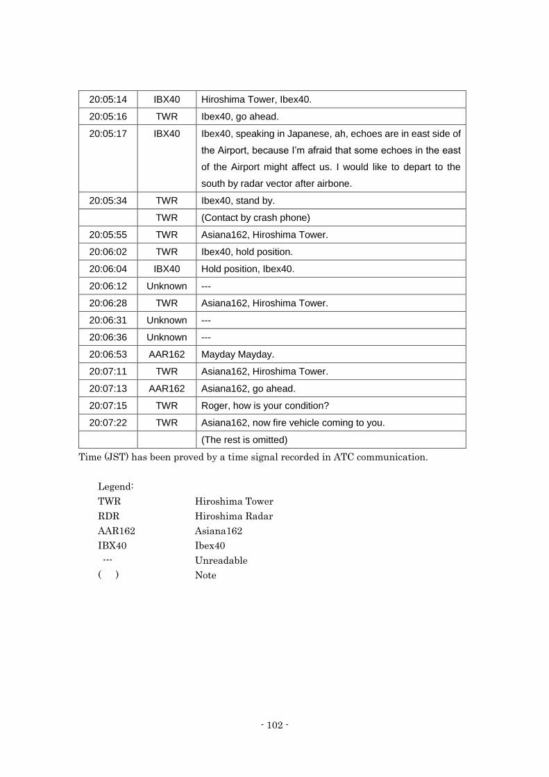
- 102 -
20:05:14 IBX40 Hiroshima Tower, Ibex40.
20:05:16 TWR Ibex40, go ahead.
20:05:17 IBX40 Ibex40, speaking in Japanese, ah, echoes are in east side of
the Airport, because I’m afraid that some echoes in the east
of the Airport might affect us. I would like to depart to the
south by radar vector after airbone.
20:05:34 TWR Ibex40, stand by.
TWR (Contact by crash phone)
20:05:55 TWR Asiana162, Hiroshima Tower.
20:06:02 TWR Ibex40, hold position.
20:06:04 IBX40 Hold position, Ibex40.
20:06:12 Unknown ---
20:06:28 TWR Asiana162, Hiroshima Tower.
20:06:31 Unknown ---
20:06:36 Unknown ---
20:06:53 AAR162 Mayday Mayday.
20:07:11 TWR Asiana162, Hiroshima Tower.
20:07:13 AAR162 Asiana162, go ahead.
20:07:15 TWR Roger, how is your condition?
20:07:22 TWR Asiana162, now fire vehicle coming to you.
(The rest is omitted)
Time (JST) has been proved by a time signal recorded in ATC communication.
Legend:
TWR Hiroshima Tower
RDR Hiroshima Radar
AAR162 Asiana162
IBX40 Ibex40
--- Unreadable
( ) Note
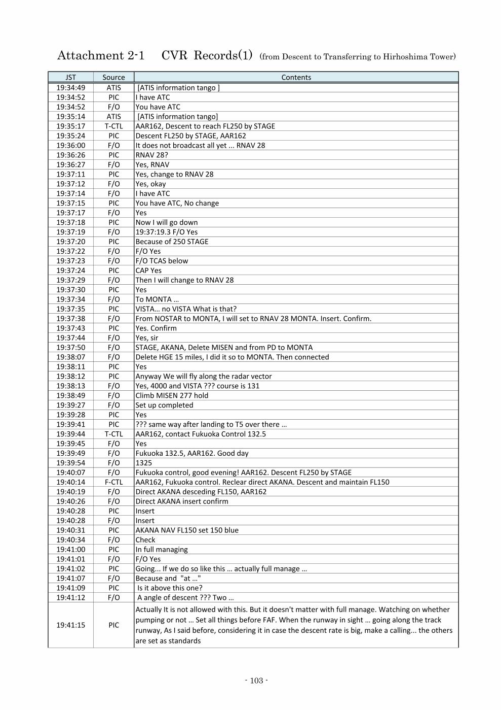
Attachment 2-1 CVR Records(1) (from Descent to Transferring to Hirhoshima Tower)
JST Source Contents
19:34:49 ATIS [ATIS information tango ]19:34:52 PIC I have ATC19:34:52 F/O You have ATC19:35:14 ATIS [ATIS information tango]19:35:17 T-CTL AAR162, Descent to reach FL250 by STAGE19:35:24 PIC Descent FL250 by STAGE, AAR16219:36:00 F/O It does not broadcast all yet ... RNAV 2819:36:26 PIC RNAV 28?19:36:27 F/O Yes, RNAV19:37:11 PIC Yes, change to RNAV 2819:37:12 F/O Yes, okay19:37:14 F/O I have ATC19:37:15 PIC You have ATC, No change19:37:17 F/O Yes19:37:18 PIC Now I will go down19:37:19 F/O 19:37:19.3 F/O Yes19:37:20 PIC Because of 250 STAGE19:37:22 F/O F/O Yes19:37:23 F/O F/O TCAS below19:37:24 PIC CAP Yes19:37:29 F/O Then I will change to RNAV 2819:37:30 PIC Yes19:37:34 F/O To MONTA …19:37:35 PIC VISTA… no VISTA What is that?19:37:38 F/O From NOSTAR to MONTA, I will set to RNAV 28 MONTA. Insert. Confirm.19:37:43 PIC Yes. Confirm19:37:44 F/O Yes, sir19:37:50 F/O STAGE, AKANA, Delete MISEN and from PD to MONTA19:38:07 F/O Delete HGE 15 miles, I did it so to MONTA. Then connected19:38:11 PIC Yes19:38:12 PIC Anyway We will fly along the radar vector19:38:13 F/O Yes, 4000 and VISTA ??? course is 13119:38:49 F/O Climb MISEN 277 hold19:39:27 F/O Set up completed19:39:28 PIC Yes19:39:41 PIC ??? same way after landing to T5 over there …19:39:44 T-CTL AAR162, contact Fukuoka Control 132.519:39:45 F/O Yes19:39:49 F/O Fukuoka 132.5, AAR162. Good day19:39:54 F/O 132519:40:07 F/O Fukuoka control, good evening! AAR162. Descent FL250 by STAGE19:40:14 F-CTL AAR162, Fukuoka control. Reclear direct AKANA. Descent and maintain FL15019:40:19 F/O Direct AKANA desceding FL150, AAR16219:40:26 F/O Direct AKANA insert confirm19:40:28 PIC Insert19:40:28 F/O Insert19:40:31 PIC AKANA NAV FL150 set 150 blue19:40:34 F/O Check19:41:00 PIC In full managing19:41:01 F/O F/O Yes19:41:02 PIC Going... If we do so like this … actually full manage …19:41:07 F/O Because and "at …"19:41:09 PIC Is it above this one?19:41:12 F/O A angle of descent ??? Two …
19:41:15 PIC
Actually It is not allowed with this. But it doesn't matter with full manage. Watching on whether
pumping or not … Set all things before FAF. When the runway in sight … going along the track
runway, As I said before, considering it in case the descent rate is big, make a calling... the others
are set as standards
- 103 -
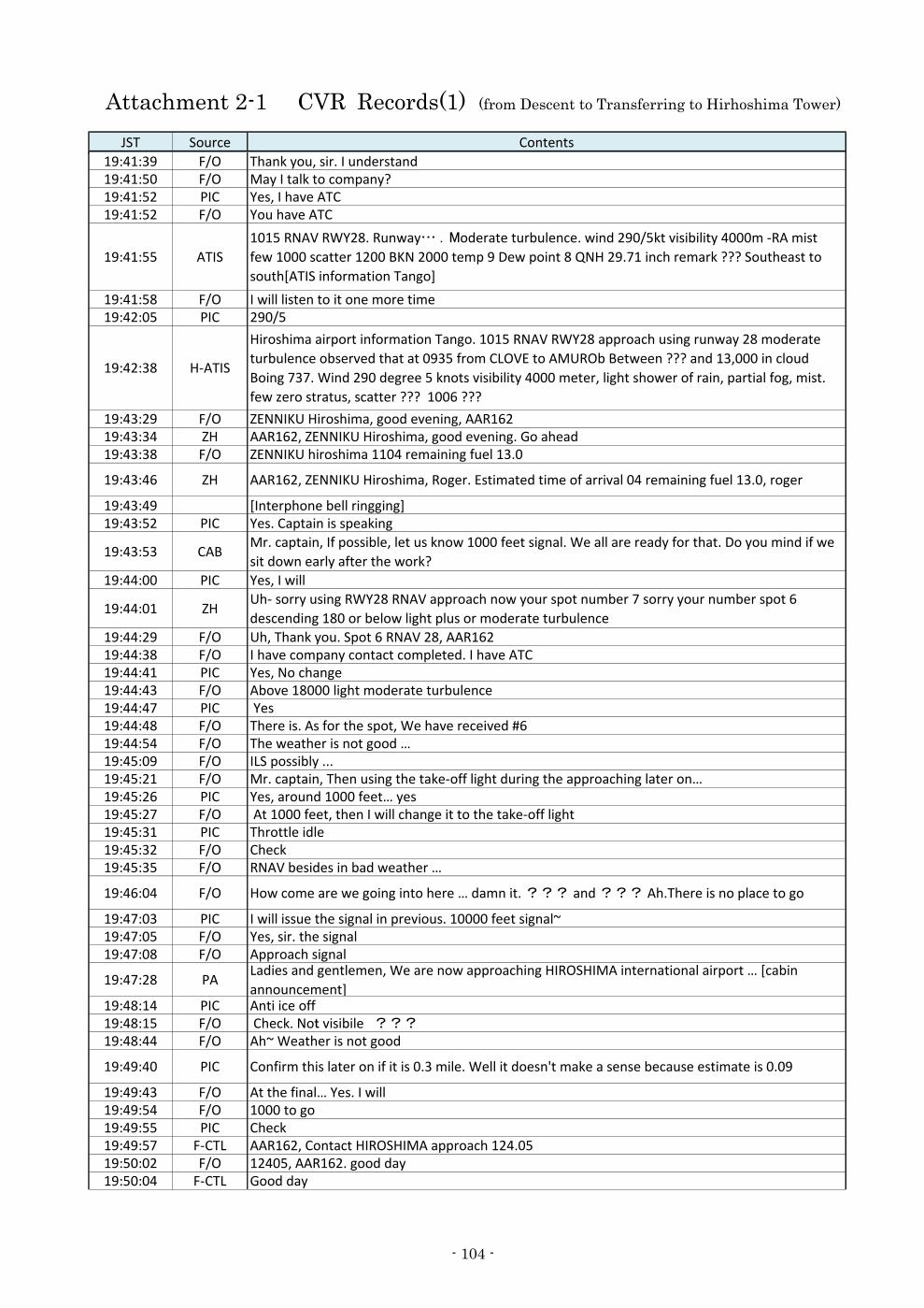
Attachment 2-1 CVR Records(1) (from Descent to Transferring to Hirhoshima Tower)
JST Source Contents
19:41:39 F/O Thank you, sir. I understand19:41:50 F/O May I talk to company?19:41:52 PIC Yes, I have ATC19:41:52 F/O You have ATC
19:41:55 ATIS
1015 RNAV RWY28. Runway… .Moderate turbulence. wind 290/5kt visibility 4000m -RA mist
few 1000 scatter 1200 BKN 2000 temp 9 Dew point 8 QNH 29.71 inch remark ??? Southeast to
south[ATIS information Tango]
19:41:58 F/O I will listen to it one more time19:42:05 PIC 290/5
19:42:38 H-ATIS
Hiroshima airport information Tango. 1015 RNAV RWY28 approach using runway 28 moderate
turbulence observed that at 0935 from CLOVE to AMUROb Between ??? and 13,000 in cloud
Boing 737. Wind 290 degree 5 knots visibility 4000 meter, light shower of rain, partial fog, mist.
few zero stratus, scatter ??? 1006 ???
19:43:29 F/O ZENNIKU Hiroshima, good evening, AAR16219:43:34 ZH AAR162, ZENNIKU Hiroshima, good evening. Go ahead19:43:38 F/O ZENNIKU hiroshima 1104 remaining fuel 13.0
19:43:46 ZH AAR162, ZENNIKU Hiroshima, Roger. Estimated time of arrival 04 remaining fuel 13.0, roger
19:43:49 [Interphone bell ringging]19:43:52 PIC Yes. Captain is speaking
19:43:53 CABMr. captain, If possible, let us know 1000 feet signal. We all are ready for that. Do you mind if we
sit down early after the work?
19:44:00 PIC Yes, I will
19:44:01 ZHUh- sorry using RWY28 RNAV approach now your spot number 7 sorry your number spot 6
descending 180 or below light plus or moderate turbulence
19:44:29 F/O Uh, Thank you. Spot 6 RNAV 28, AAR16219:44:38 F/O I have company contact completed. I have ATC19:44:41 PIC Yes, No change19:44:43 F/O Above 18000 light moderate turbulence19:44:47 PIC Yes19:44:48 F/O There is. As for the spot, We have received #619:44:54 F/O The weather is not good …19:45:09 F/O ILS possibly ...19:45:21 F/O Mr. captain, Then using the take-off light during the approaching later on…19:45:26 PIC Yes, around 1000 feet… yes19:45:27 F/O At 1000 feet, then I will change it to the take-off light19:45:31 PIC Throttle idle19:45:32 F/O Check19:45:35 F/O RNAV besides in bad weather …
19:46:04 F/O How come are we going into here … damn it. ??? and ??? Ah.There is no place to go
19:47:03 PIC I will issue the signal in previous. 10000 feet signal~19:47:05 F/O Yes, sir. the signal19:47:08 F/O Approach signal
19:47:28 PALadies and gentlemen, We are now approaching HIROSHIMA international airport … [cabin
announcement]19:48:14 PIC Anti ice off19:48:15 F/O Check. Not visibile ???19:48:44 F/O Ah~ Weather is not good
19:49:40 PIC Confirm this later on if it is 0.3 mile. Well it doesn't make a sense because estimate is 0.09
19:49:43 F/O At the final… Yes. I will19:49:54 F/O 1000 to go19:49:55 PIC Check19:49:57 F-CTL AAR162, Contact HIROSHIMA approach 124.0519:50:02 F/O 12405, AAR162. good day19:50:04 F-CTL Good day
- 104 -
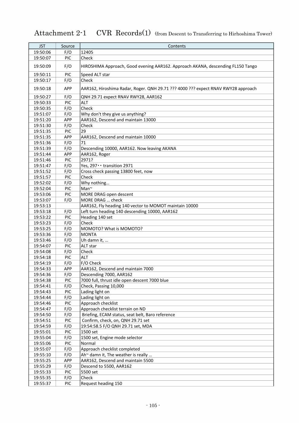
Attachment 2-1 CVR Records(1) (from Descent to Transferring to Hirhoshima Tower)
JST Source Contents
19:50:06 F/O 1240519:50:07 PIC Check
19:50:09 F/O HIROSHIMA Approach, Good evening AAR162. Approach AKANA, descending FL150 Tango
19:50:11 PIC Speed ALT star19:50:17 F/O Check
19:50:18 APP AAR162, Hiroshima Radar, Roger. QNH 29.71 ??? 4000 ??? expect RNAV RWY28 approach
19:50:27 F/O QNH 29.71 expect RNAV RWY28, AAR16219:50:33 PIC ALT19:50:35 F/O Check19:51:07 F/O Why don't they give us anything?19:51:20 APP AAR162, Descend and maintain 1300019:51:30 F/O Check19:51:35 PIC 2919:51:35 APP AAR162, Descend and maintain 1000019:51:36 F/O 7119:51:39 F/O Descending 10000, AAR162. Now leaving AKANA19:51:44 APP AAR162, Roger19:51:46 PIC 2971?19:51:47 F/O Yes, 297・・ transition 297119:51:52 F/O Cross check passing 13800 feet, now19:51:57 PIC Check19:52:02 F/O Why nothing…19:52:04 PIC Man~19:53:06 PIC MORE DRAG open descent19:53:07 F/O MORE DRAG … check19:53:13 AAR162, Fly heading 140 vector to MOMOT maintain 1000019:53:18 F/O Left turn heading 140 descending 10000, AAR16219:53:22 PIC Heading 140 set19:53:23 F/O Check19:53:25 F/O MOMOTO? What is MOMOTO?19:53:36 F/O MONTA19:53:46 F/O Uh damn it, …19:54:07 PIC ALT star19:54:08 F/O Check19:54:18 PIC ALT19:54:19 F/O F/O Check19:54:33 APP AAR162, Descend and maintain 700019:54:36 F/O Descending 7000, AAR16219:54:38 PIC 7000 full, thrust idle open descent 7000 blue19:54:41 F/O Check, Passing 10,00019:54:43 PIC Lading light on19:54:44 F/O Lading light on19:54:46 PIC Approach checklist19:54:47 F/O Approach checklist terrain on ND19:54:50 F/O Briefing, ECAM status, seat belt, Baro reference19:54:51 PIC Confirm, check, on, QNH 29.71 set19:54:59 F/O 19:54:58.5 F/O QNH 29.71 set, MDA19:55:01 PIC 1500 set19:55:04 F/O 1500 set, Engine mode selector19:55:06 PIC Normal19:55:07 F/O Approach checklist completed19:55:10 F/O Ah~ damn it, The weather is really …19:55:25 APP AAR162, Descend and maintain 550019:55:29 F/O Descend to 5500, AAR16219:55:33 PIC 5500 set19:55:35 F/O Check19:55:37 PIC Request heading 150
- 105 -
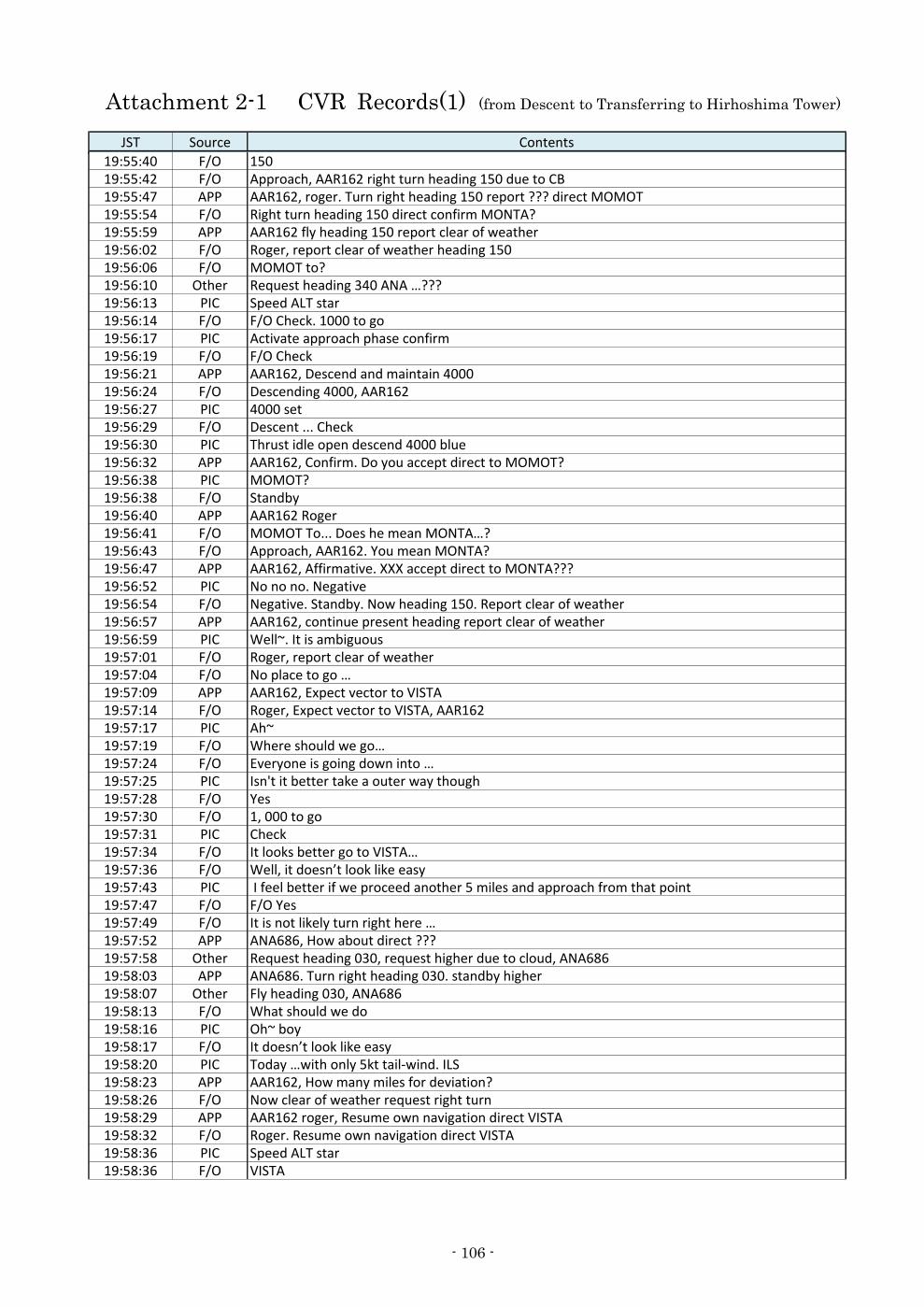
Attachment 2-1 CVR Records(1) (from Descent to Transferring to Hirhoshima Tower)
JST Source Contents
19:55:40 F/O 15019:55:42 F/O Approach, AAR162 right turn heading 150 due to CB19:55:47 APP AAR162, roger. Turn right heading 150 report ??? direct MOMOT19:55:54 F/O Right turn heading 150 direct confirm MONTA?19:55:59 APP AAR162 fly heading 150 report clear of weather19:56:02 F/O Roger, report clear of weather heading 15019:56:06 F/O MOMOT to?19:56:10 Other Request heading 340 ANA …???19:56:13 PIC Speed ALT star19:56:14 F/O F/O Check. 1000 to go19:56:17 PIC Activate approach phase confirm19:56:19 F/O F/O Check19:56:21 APP AAR162, Descend and maintain 400019:56:24 F/O Descending 4000, AAR16219:56:27 PIC 4000 set19:56:29 F/O Descent ... Check19:56:30 PIC Thrust idle open descend 4000 blue19:56:32 APP AAR162, Confirm. Do you accept direct to MOMOT?19:56:38 PIC MOMOT?19:56:38 F/O Standby19:56:40 APP AAR162 Roger19:56:41 F/O MOMOT To... Does he mean MONTA…?19:56:43 F/O Approach, AAR162. You mean MONTA?19:56:47 APP AAR162, Affirmative. XXX accept direct to MONTA???19:56:52 PIC No no no. Negative19:56:54 F/O Negative. Standby. Now heading 150. Report clear of weather19:56:57 APP AAR162, continue present heading report clear of weather19:56:59 PIC Well~. It is ambiguous19:57:01 F/O Roger, report clear of weather19:57:04 F/O No place to go …19:57:09 APP AAR162, Expect vector to VISTA19:57:14 F/O Roger, Expect vector to VISTA, AAR16219:57:17 PIC Ah~19:57:19 F/O Where should we go…19:57:24 F/O Everyone is going down into …19:57:25 PIC Isn't it better take a outer way though19:57:28 F/O Yes19:57:30 F/O 1, 000 to go19:57:31 PIC Check19:57:34 F/O It looks better go to VISTA…19:57:36 F/O Well, it doesn’t look like easy19:57:43 PIC I feel better if we proceed another 5 miles and approach from that point19:57:47 F/O F/O Yes19:57:49 F/O It is not likely turn right here …19:57:52 APP ANA686, How about direct ???19:57:58 Other Request heading 030, request higher due to cloud, ANA68619:58:03 APP ANA686. Turn right heading 030. standby higher19:58:07 Other Fly heading 030, ANA68619:58:13 F/O What should we do19:58:16 PIC Oh~ boy19:58:17 F/O It doesn’t look like easy19:58:20 PIC Today …with only 5kt tail-wind. ILS19:58:23 APP AAR162, How many miles for deviation?19:58:26 F/O Now clear of weather request right turn19:58:29 APP AAR162 roger, Resume own navigation direct VISTA19:58:32 F/O Roger. Resume own navigation direct VISTA19:58:36 PIC Speed ALT star19:58:36 F/O VISTA
- 106 -
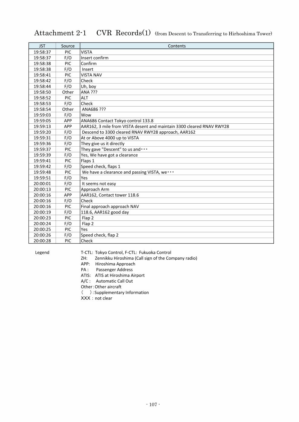
Attachment 2-1 CVR Records(1) (from Descent to Transferring to Hirhoshima Tower)
JST Source Contents
19:58:37 PIC VISTA19:58:37 F/O Insert confirm19:58:38 PIC Confirm19:58:38 F/O Insert19:58:41 PIC VISTA NAV19:58:42 F/O Check19:58:44 F/O Uh, boy19:58:50 Other ANA ???19:58:52 PIC ALT19:58:53 F/O Check19:58:54 Other ANA686 ???19:59:03 F/O Wow19:59:05 APP ANA686 Contact Tokyo control 133.819:59:13 APP AAR162, 3 mile from VISTA desent and maintain 3300 cleared RNAV RWY2819:59:20 F/O Descend to 3300 cleared RNAV RWY28 approach, AAR16219:59:31 F/O At or Above 4000 up to VISTA19:59:36 F/O They give us it directly19:59:37 PIC They gave "Descent" to us and・・・19:59:39 F/O Yes, We have got a clearance19:59:41 PIC Flaps 119:59:42 F/O Speed check, flaps 119:59:48 PIC We have a clearance and passing VISTA, we・・・19:59:51 F/O Yes20:00:01 F/O It seems not easy20:00:13 PIC Approach Arm20:00:16 APP AAR162, Contact tower 118.620:00:16 F/O Check20:00:16 PIC Final approach approach NAV20:00:19 F/O 118.6, AAR162 good day20:00:23 PIC Flap 220:00:24 F/O Flap 220:00:25 PIC Yes20:00:26 F/O Speed check, flap 220:00:28 PIC Check
Legend T-CTL: Tokyo Control, F-CTL: Fukuoka ControlZH: Zennikku Hiroshima (Call sign of the Company radio)APP: Hiroshima ApproachPA : Passenger AddressATIS: ATIS at Hiroshima AirportA/C : Automatic Call OutOther:Other aircraft( ):Supplementary InformationXXX : not clear
- 107 -
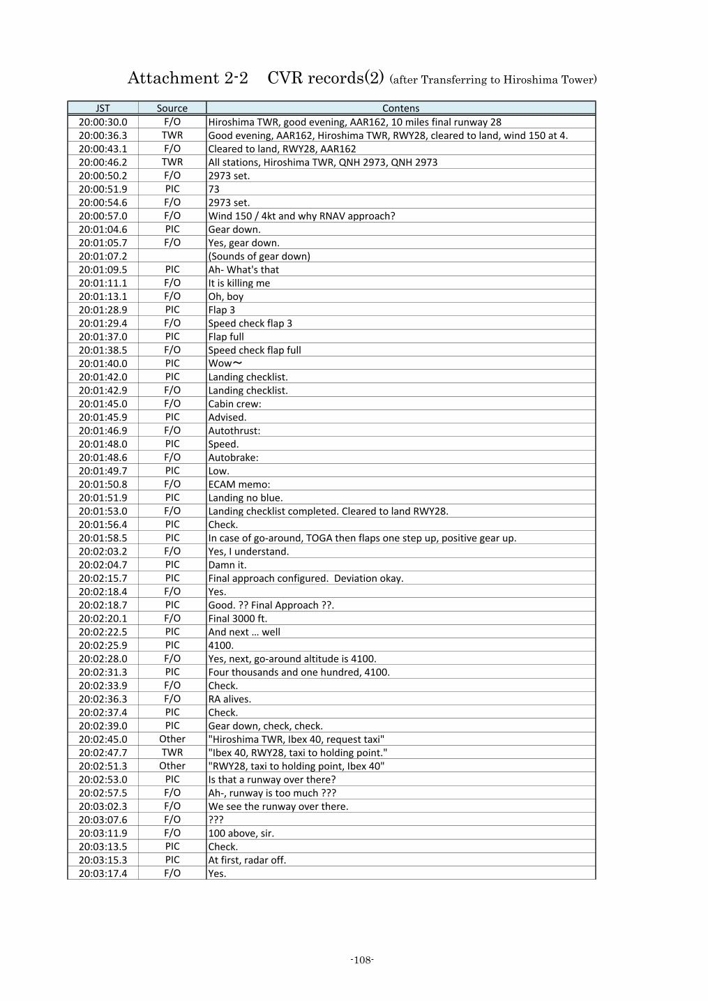
Attachment 2-2 CVR records(2) (after Transferring to Hiroshima Tower)
JST Source Contens20:00:30.0 F/O Hiroshima TWR, good evening, AAR162, 10 miles final runway 2820:00:36.3 TWR Good evening, AAR162, Hiroshima TWR, RWY28, cleared to land, wind 150 at 4.20:00:43.1 F/O Cleared to land, RWY28, AAR16220:00:46.2 TWR All stations, Hiroshima TWR, QNH 2973, QNH 297320:00:50.2 F/O 2973 set.20:00:51.9 PIC 7320:00:54.6 F/O 2973 set.20:00:57.0 F/O Wind 150 / 4kt and why RNAV approach?20:01:04.6 PIC Gear down.20:01:05.7 F/O Yes, gear down.20:01:07.2 (Sounds of gear down)20:01:09.5 PIC Ah- What's that20:01:11.1 F/O It is killing me20:01:13.1 F/O Oh, boy20:01:28.9 PIC Flap 320:01:29.4 F/O Speed check flap 320:01:37.0 PIC Flap full20:01:38.5 F/O Speed check flap full20:01:40.0 PIC Wow~20:01:42.0 PIC Landing checklist.20:01:42.9 F/O Landing checklist.20:01:45.0 F/O Cabin crew:20:01:45.9 PIC Advised.20:01:46.9 F/O Autothrust:20:01:48.0 PIC Speed.20:01:48.6 F/O Autobrake:20:01:49.7 PIC Low.20:01:50.8 F/O ECAM memo:20:01:51.9 PIC Landing no blue.20:01:53.0 F/O Landing checklist completed. Cleared to land RWY28.20:01:56.4 PIC Check.20:01:58.5 PIC In case of go-around, TOGA then flaps one step up, positive gear up.20:02:03.2 F/O Yes, I understand.20:02:04.7 PIC Damn it.20:02:15.7 PIC Final approach configured. Deviation okay.20:02:18.4 F/O Yes.20:02:18.7 PIC Good. ?? Final Approach ??.20:02:20.1 F/O Final 3000 ft.20:02:22.5 PIC And next … well20:02:25.9 PIC 4100.20:02:28.0 F/O Yes, next, go-around altitude is 4100.20:02:31.3 PIC Four thousands and one hundred, 4100.20:02:33.9 F/O Check.20:02:36.3 F/O RA alives.20:02:37.4 PIC Check.20:02:39.0 PIC Gear down, check, check.20:02:45.0 Other "Hiroshima TWR, Ibex 40, request taxi"20:02:47.7 TWR "Ibex 40, RWY28, taxi to holding point."20:02:51.3 Other "RWY28, taxi to holding point, Ibex 40"20:02:53.0 PIC Is that a runway over there?20:02:57.5 F/O Ah-, runway is too much ???20:03:02.3 F/O We see the runway over there.20:03:07.6 F/O ???20:03:11.9 F/O 100 above, sir.20:03:13.5 PIC Check.20:03:15.3 PIC At first, radar off.20:03:17.4 F/O Yes.
-108-
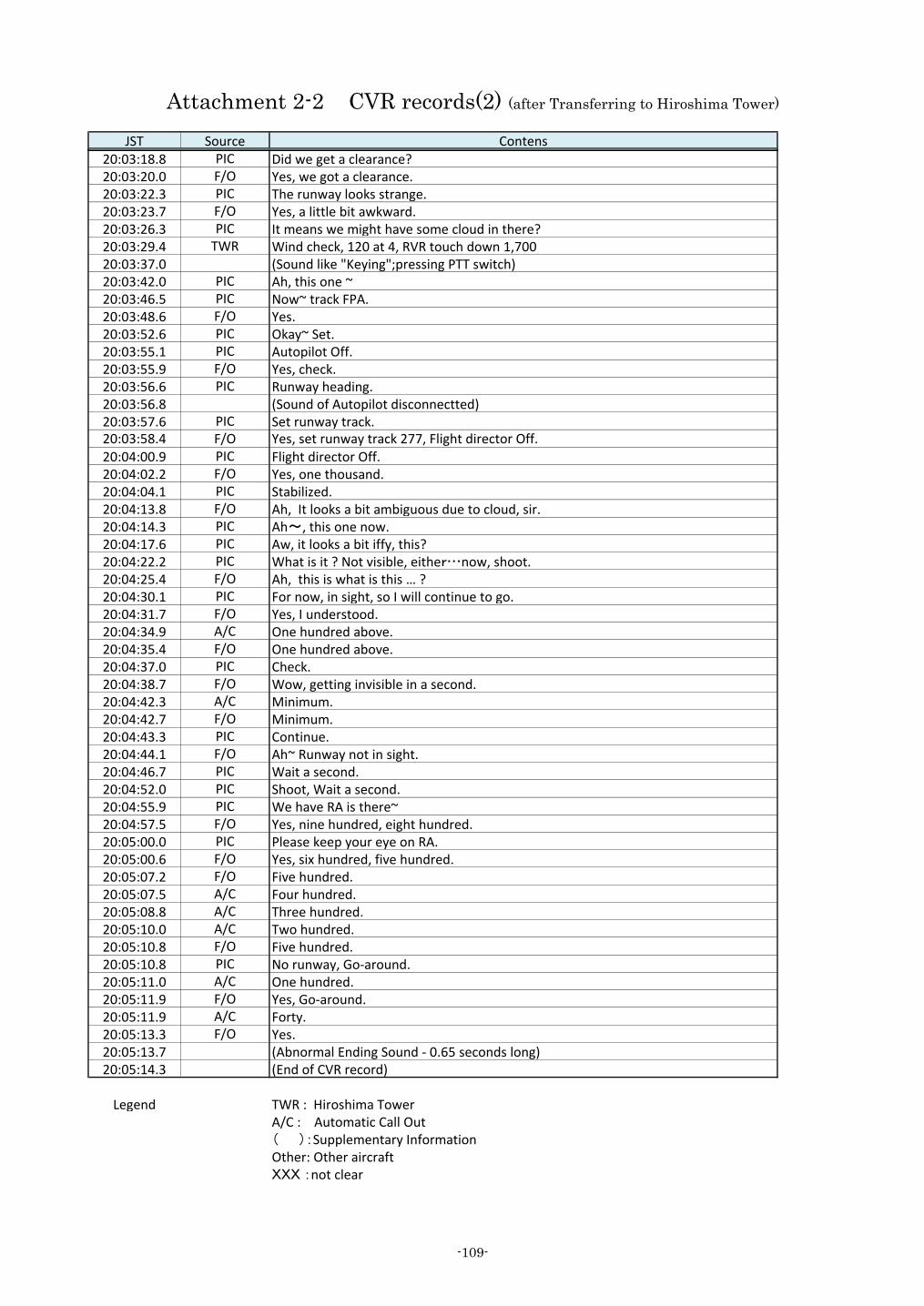
Attachment 2-2 CVR records(2) (after Transferring to Hiroshima Tower)
JST Source Contens20:03:18.8 PIC Did we get a clearance?20:03:20.0 F/O Yes, we got a clearance.20:03:22.3 PIC The runway looks strange.20:03:23.7 F/O Yes, a little bit awkward.20:03:26.3 PIC It means we might have some cloud in there?20:03:29.4 TWR Wind check, 120 at 4, RVR touch down 1,70020:03:37.0 (Sound like "Keying";pressing PTT switch)20:03:42.0 PIC Ah, this one ~20:03:46.5 PIC Now~ track FPA.20:03:48.6 F/O Yes.20:03:52.6 PIC Okay~ Set.20:03:55.1 PIC Autopilot Off.20:03:55.9 F/O Yes, check.20:03:56.6 PIC Runway heading.20:03:56.8 (Sound of Autopilot disconnectted)20:03:57.6 PIC Set runway track.20:03:58.4 F/O Yes, set runway track 277, Flight director Off.20:04:00.9 PIC Flight director Off.20:04:02.2 F/O Yes, one thousand.20:04:04.1 PIC Stabilized.20:04:13.8 F/O Ah, It looks a bit ambiguous due to cloud, sir.20:04:14.3 PIC Ah~, this one now.20:04:17.6 PIC Aw, it looks a bit iffy, this?20:04:22.2 PIC What is it ? Not visible, either…now, shoot.20:04:25.4 F/O Ah, this is what is this … ?20:04:30.1 PIC For now, in sight, so I will continue to go.20:04:31.7 F/O Yes, I understood.20:04:34.9 A/C One hundred above.20:04:35.4 F/O One hundred above.20:04:37.0 PIC Check.20:04:38.7 F/O Wow, getting invisible in a second.20:04:42.3 A/C Minimum.20:04:42.7 F/O Minimum.20:04:43.3 PIC Continue.20:04:44.1 F/O Ah~ Runway not in sight.20:04:46.7 PIC Wait a second.20:04:52.0 PIC Shoot, Wait a second.20:04:55.9 PIC We have RA is there~20:04:57.5 F/O Yes, nine hundred, eight hundred.20:05:00.0 PIC Please keep your eye on RA.20:05:00.6 F/O Yes, six hundred, five hundred.20:05:07.2 F/O Five hundred.20:05:07.5 A/C Four hundred.20:05:08.8 A/C Three hundred.20:05:10.0 A/C Two hundred.20:05:10.8 F/O Five hundred.20:05:10.8 PIC No runway, Go-around.20:05:11.0 A/C One hundred.20:05:11.9 F/O Yes, Go-around.20:05:11.9 A/C Forty.20:05:13.3 F/O Yes.20:05:13.7 (Abnormal Ending Sound - 0.65 seconds long)20:05:14.3 (End of CVR record)
Legend TWR : Hiroshima TowerA/C : Automatic Call Out( ):Supplementary InformationOther: Other aircraftXXX :not clear
-109-