Embed Size (px)
Citation preview
AirChek® XR5000Operating Instructions
SKC Inc.863 Valley View Road
Eighty Four, PA 15330 USA
Form #38047 Rev 0805
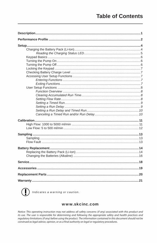
Description .......................................................................................................................1
Performance Profi le ........................................................................................................2
Setup .................................................................................................................................4Charging the Battery Pack (Li-Ion) ...........................................................................4
Reading the Charging Status LED ................................................................5Keypad Basics .........................................................................................................6Turning the Pump On ...............................................................................................6Turning the Pump Off ...............................................................................................6Locking the Keypad .................................................................................................7Checking Battery Charge Level ...............................................................................7Accessing User Setup Functions .............................................................................7
Entering Functions ........................................................................................7Exiting Functions ...........................................................................................7
User Setup Functions ..............................................................................................8Function Overview ........................................................................................8Clearing Accumulated Run Time ...................................................................8Setting Flow Rate ..........................................................................................8Setting a Timed Run......................................................................................9Setting a Run Delay ......................................................................................9Setting a Run Delay and Timed Run ...........................................................10Canceling a Timed Run and/or Run Delay ..................................................10
Calibration ...................................................................................................................... 11High Flow: 1000 to 5000 ml/min ............................................................................ 11Low Flow: 5 to 500 ml/min .....................................................................................12
Sampling ........................................................................................................................13Sampling ................................................................................................................13Flow Fault ..............................................................................................................13
Battery Replacement .....................................................................................................14Replacing the Battery Pack (Li-Ion) .......................................................................14Changing the Batteries (Alkaline) ..........................................................................16
Service ............................................................................................................................18
Accessories ...................................................................................................................19
Replacement Parts ........................................................................................................20
Warranty .........................................................................................................................21
Indicates a warning or caution.
www.skcinc.com
Notice: This operating instruction may not address all safety concerns (if any) associated with this product and its use. The user is responsible for determining and following the appropriate safety and health practices and regulatory limitations (if any) before using the product. The information contained in this document should not be construed as legal advice, opinion, or as a fi nal authority on legal or regulatory procedures.
Table of Contents
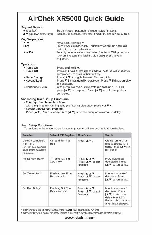
AirChek XR5000 Quick GuideKeypad Basics
(star key) Scrolls through parameters in user setup functions. (up/down arrow keys) Increase or decrease fl ow rate, timed run, and run delay time.
Key Sequences Press keys individually.
[ ] Press keys simultaneously. Toggles between Run and Hold and exits user setup functions.
Security code to access user setup functions. With pump in a non-running state (no fl ashing blue LED), press keys in sequence.
Operation• Pump On Press and hold .• Pump Off Press and hold through countdown. Auto-off will shut down
pump after 5 minutes without activity.• Mode Change Press [ ] to toggle between Run and Hold.• Keypad Lock Press 5 times quickly to activate. Press 5 times quickly
to deactivate.• Continuous Run With pump in a non-running state (no fl ashing blue LED),
press [ ] to run pump. Press [ ] to Hold pump when completed.
Accessing User Setup Functions• Entering User Setup Functions
With pump in a non-running state (no fl ashing blue LED), press .• Exiting User Setup Functions
Press [ ]. Pump is ready. Press [ ] to run the pump or to start a run delay.
User Setup FunctionsTo navigate while in user setup functions, press until the desired function displays.
Function When LCD Displays User Action ResultClear Accumulated Run TimeFunction only available when accumulated run time exists.
CLr and fl ashing Hold
Press [ ]. Clears run and run time and exits func-tions. Press [ ] to run pump.
Adjust Flow Rate* “---” and fl ashing ADJ Flow
Press or . Press [ ] to exit functions.
Flow increases/decreases. Press [ ] to run pump.
Set Timed Run† Flashing Set Timed Run and min
Press or . Press [ ] to exit functions.
Minutes increase/decrease. Press [ ] to run pump.
Set Run Delay† Flashing Set Run Delay and min
Press or . Press [ ] to exit functions.
Minutes increase/decrease. Press [ ] to start run delay. Blue LED fl ashes. Pump starts after delay elapses.
* Changing fl ow rate in user setup functions will not clear accumulated run time.† Changing timed run and/or run delay settings in user setup functions will clear accumulated run time.
www.skcinc.com
1
Description
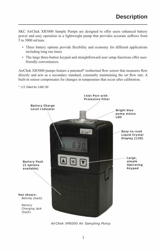
SKC AirChek XR5000 Sample Pumps are designed to offer users enhanced battery power and easy operation in a lightweight pump that provides accurate airfl ows from 5 to 5000 ml/min.
• Three battery options provide fl exibility and economy for different applications including long run times
• The large three-button keypad and straightforward user setup functions offer user-friendly conveniences.
AirChek XR5000 pumps feature a patented* isothermal fl ow sensor that measures fl ow directly and acts as a secondary standard, constantly maintaining the set fl ow rate. A built-in sensor compensates for changes in temperature that occur after calibration.
* U.S. Patent No. 5,892,160
Battery Charge Level Indicator
Inlet Port with Protective Filter
Easy-to-readLiquid CrystalDisplay (LCD)
Large,simpleOperatingKeypad
Battery Pack (3 options available)
Not shown:Beltclip (back)
BatteryCharging Jack(back)
AirChek XR5000 Air Sampling Pump
Bright blue pump status LED
2
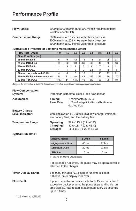
Flow Range: 1000 to 5000 ml/min (5 to 500 ml/min requires optional low fl ow adapter kit)
Compensation Range: 5000 ml/min at 10 inches water back pressure4000 ml/min at 20 inches water back pressure2000 ml/min at 50 inches water back pressure
Typical Back Pressure of Sampling Media (inches water)
Compare the information in this table to pump compensation range to determine appropriate applications.
Flow CompensationSystem: Patented* isothermal closed loop fl ow sensor
Accuracies: Timing: 1 min/month @ 25 C Flow Rate: ± 5% of set-point after calibration to
desired fl ow
Battery Charge Level Indicator: Icon displays on LCD at full, mid, low charge, imminent
low battery fault, and low battery fault.
Temperature Range: Operating: 32 to 113 F (0 to 45 C) Charging: 32 to 113 F (0 to 45 C) Storage: -4 to 113 F (-20 to 45 C)
Typical Run Time†:XR5000 Model 2 L/min 5 L/min
High-power Li-Ion 40 hrs 22 hrs
Standard Li-Ion 20 hrs 11 hrs
Alkaline 18 hrs 8 hrs
† Using a 37-mm 0.8-μm MCE filter
For extended run times, the pump may be operated while attached to the charger.
Timer Display Range: 1 to 9999 minutes (6.8 days). If run time exceeds 6.8 days, timer display rolls over.
Flow Fault: If pump is unable to compensate for > 15 seconds due to excessive back pressure, the pump stops and holds run time display. Auto-restart is attempted every 15 seconds up to 5 times.
Performance Profi le
* U.S. Patent No. 5,892,160
Flow Rate (L/min) 1.0 1.5 2.0 2.5 3.0 3.5 4.0 5.0Filter/Pore Size (μm)25-mm MCE/0.8 6 9 12 15 18 21 25 3125-mm MCE/0.45 14 22 28 35 40 44 50 6337-mm MCE/0.8 2 3 4 5 6 7 9 1137-mm PVC/5.0 1 1 2 2 2.5 3 3 437-mm, polycarbonate/0.45 4 6 8 10 12 15 17 2125-mm MCE/0.45 microvacuum 21 31 40 48 59 69 79 10037-mm Tefl on/1.0 7.5 11 14.5 19 22 26 30 40
3
(model dependent)
Performance Profi le
Low Battery Fault: 15 seconds to sleep
Auto-off: 5 minutes of inactivity
Battery Pack: High-power Li-Ion (4 cell), rechargeable, 7.4 V, 4.4 Ah capacity (Cat. No. P85004 for UL Listed pump)
or Standard Li-Ion (2 cell), rechargeable, 7.4 V, 2.2 Ah
capacity (Cat. No. P85002 for UL Listed pump) or Alkaline (6 cells), disposable, size AA, 1.5 V (nominal), Cat.
No. P75715 - not UL Listed for intrinsic safety
Battery Recharge Time: Standard Li-Ion (2 cell): approximately 4 hrsHigh-power Li-Ion (4 cell): approximately 8 hrs
Size: High-power Li-Ion and alkaline models: 5.5 x 3 x 2.3 in (14 x 7.6 x 5.8 cm)
Standard Li-Ion model: 4.3 x 3 x 2.3 in (10.9 x 7.6 x 5.8 cm)
Weight: High-power Li-Ion: 21 oz (0.6 kg) Standard Li-Ion model: 16 oz (0.45 kg)Alkaline model: 17 oz (0.48 kg)
Case: Anti-static plastic
RFI/EMI Shielding: CE marked for RFI/EMI protection
Approvals: for use in hazardous locations. Models that are UL Listed for intrinsic safety contain the logo on the label. These models must be used with battery pack Cat. No. P85004 or P85002 to maintain the UL intrinsic safety listing.
Cautions:• For safe operation in hazardous locations, ensure the pump label contains the
logo and the battery pack label contains Cat. No. P85004 or P85002. Use of any other battery pack (including alkaline) or device to power the pump voids the UL Listing for intrinsic safety.
• Use only the charger and battery packs designed for the AirChek XR5000 pump to ensure reliable performance and retain the SKC warranty.
• Use only SKC-approved parts to ensure reliable performance, retain the SKC warranty, and to maintain the UL Listing for intrinsic safety.
(with SKC-approved charger)
4
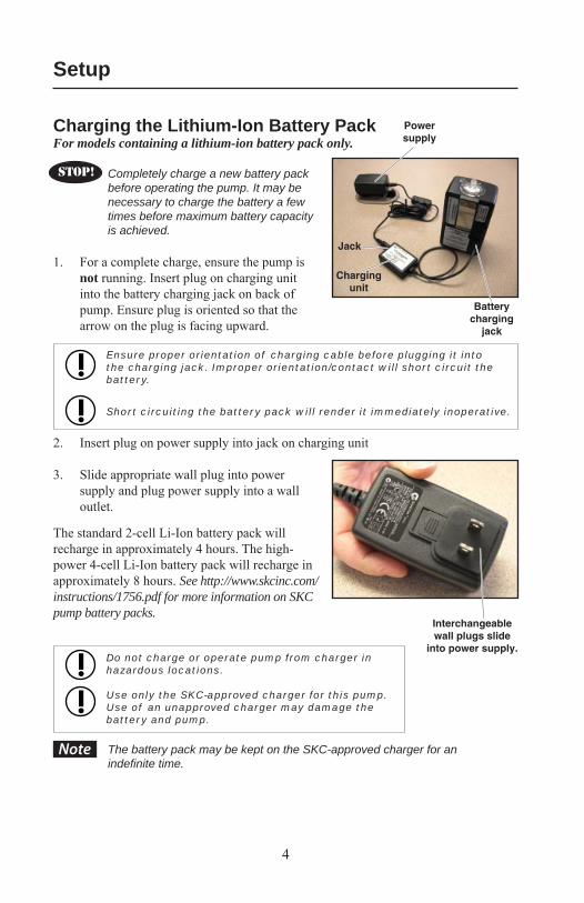
Charging the Lithium-Ion Battery PackFor models containing a lithium-ion battery pack only.
Completely charge a new battery pack before operating the pump. It may be necessary to charge the battery a few times before maximum battery capacity is achieved.
1. For a complete charge, ensure the pump is not running. Insert plug on charging unit into the battery charging jack on back of pump. Ensure plug is oriented so that the arrow on the plug is facing upward.
Ensure proper orientation of charging cable before plugging it into the charging jack. Improper orientation/contact will short circuit the battery.
Short circuiting the battery pack will render it immediately inoperative.
2. Insert plug on power supply into jack on charging unit
3. Slide appropriate wall plug into power supply and plug power supply into a wall outlet.
The standard 2-cell Li-Ion battery pack will recharge in approximately 4 hours. The high-power 4-cell Li-Ion battery pack will recharge in approximately 8 hours. See http://www.skcinc.com/instructions/1756.pdf for more information on SKC pump battery packs.
Do not charge or operate pump from charger in hazardous locations.
Use only the SKC-approved charger for this pump. Use of an unapproved charger may damage the battery and pump.
The battery pack may be kept on the SKC-approved charger for an indefi nite time.
Power supply
Battery charging
jack
Jack
Charging unit
Interchangeable wall plugs slide
into power supply.
STOP!
Setup
Note
5
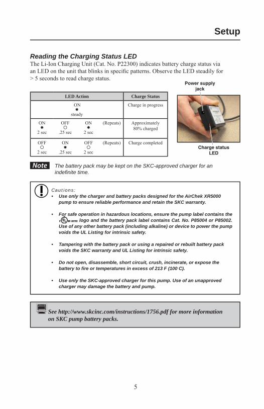
Power supply jack
Charge status LED
See http://www.skcinc.com/instructions/1756.pdf for more information on SKC pump battery packs.
Reading the Charging Status LEDThe Li-Ion Charging Unit (Cat. No. P22300) indicates battery charge status via an LED on the unit that blinks in specifi c patterns. Observe the LED steadily for > 5 seconds to read charge status.
LED Action Charge Status
ON
steady
Charge in progress
ON
2 sec
OFF
.25 sec
ON
2 sec
(Repeats) Approximately 80% charged
OFF
2 sec
ON
.25 sec
OFF
2 sec
(Repeats) Charge completed
The battery pack may be kept on the SKC-approved charger for an indefi nite time.
Cautions:• Use only the charger and battery packs designed for the AirChek XR5000
pump to ensure reliable performance and retain the SKC warranty.
• For safe operation in hazardous locations, ensure the pump label contains the logo and the battery pack label contains Cat. No. P85004 or P85002.
Use of any other battery pack (including alkaline) or device to power the pump voids the UL Listing for intrinsic safety.
• Tampering with the battery pack or using a repaired or rebuilt battery pack voids the SKC warranty and UL Listing for intrinsic safety.
• Do not open, disassemble, short circuit, crush, incinerate, or expose the battery to fi re or temperatures in excess of 213 F (100 C).
• Use only the SKC-approved charger for this pump. Use of an unapproved charger may damage the battery and pump.
Setup
Note
6
Setup
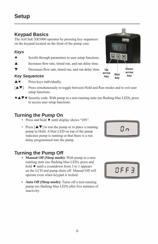
Keypad BasicsThe AirChek XR5000 operates by pressing key sequences on the keypad located on the front of the pump case.
Keys Scrolls through parameters in user setup functions.
Increases fl ow rate, timed run, and run delay time.
Decreases fl ow rate, timed run, and run delay time.
Key Sequences Press keys individually.
[ ] Press simultaneously to toggle between Hold and Run modes and to exit user setup functions.
Security code. With pump in a non-running state (no fl ashing blue LED), press to access user setup functions.
Turning the Pump On• Press and hold until display shows “ON”.
• Press [ ] to run the pump or to place a running pump in Hold. A blue LED on top of the pump indicates pump is running or that there is a run delay programmed into the pump.
Turning the Pump Off• Manual Off (Sleep mode): With pump in a non-
running state (no flashing blue LED), press and hold until a countdown from 3 to 1 appears on the LCD and pump shuts off. Manual Off will operate even when keypad is locked.
• Auto Off (Sleep mode): Turns off a non-running pump (no flashing blue LED) after five minutes of inactivity.
Down arrow keyStar
key
Up arrow key
7
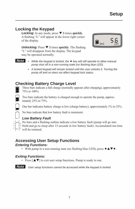
Locking the KeypadLocking: In any mode, press 5 times quickly. A flashing “L” will appear in the lower right corner of the display.
Unlocking: Press 5 times quickly. The flashing “L” will disappear from the display. The keypad may be operated normally.
• While the keypad is locked, the key will still operate to allow manual pump shut off in a non-running state (no fl ashing blue LED).
• A locked keypad will remain locked until the user unlocks it. Turning the pump off and on does not affect keypad lock status.
Checking Battery Charge LevelThree bars indicate a full charge (normally appears after charging), approximately 75% to 100%.
Two bars indicate the battery is charged enough to operate the pump, approx-imately 25% to 75%.
One bar indicates battery charge is low (charge battery), approximately 1% to 25%.
No bars indicate that low battery fault is imminent.
Low Battery FaultNo bars and a fl ashing outline indicate a low battery fault (pump will go into Hold and go to sleep after 15 seconds in low battery fault). Accumulated run time will be retained.
Accessing User Setup FunctionsEntering Functions:
• With pump in a non-running state (no flashing blue LED), press .
Exiting Functions:• Press [ ] to exit user setup functions. Pump is ready to run.
User setup functions cannot be accessed while the keypad is locked.
Setup
Note
Note
8
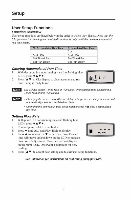
User Setup FunctionsFunction OverviewUser setup functions are listed below in the order in which they display. Note that the CLr function for clearing accumulated run time is only available when accumulated run time exists.
No Accumulated Run Time Accumulated Run TimeCLr
ADJ Flow ADJ FlowSet Timed Run Set Timed RunSet Run Delay Set Run Delay
Clearing Accumulated Run Time1. With the pump in a non-running state (no fl ashing blue
LED), press .2. Press [ ] at CLr display to clear accumulated run
time. Pump is ready to run.
CLr will not cancel Timed Run or Run Delay time settings (see Canceling a Timed Run and/or Run Delay).
• Changing the timed run and/or run delay settings in user setup functions will automatically clear accumulated run time.
• Changing the fl ow rate in user setup functions will not clear accumulated run time.
Setting Flow Rate1. With pump in a non-running state (no fl ashing blue
LED), press .2. Connect pump inlet to a calibrator.3. Press until ADJ and Flow fl ash on display.4. Press to increase or to decrease fl ow. Dashed
lines will move up and down on the LCD to indicate direction of adjustment. Flow rate will not display on the pump LCD. Observe the calibrator for fl ow reading.
5. Press [ ] to accept fl ow setting and to exit user setup functions.
See Calibration for instructions on calibrating pump fl ow rate.
Setup
Note
Note
9
Note
Note
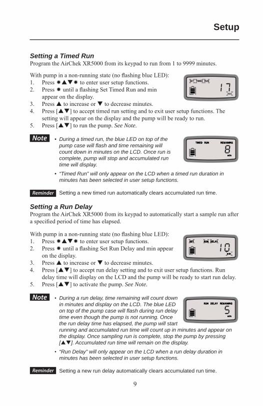
Setting a Timed RunProgram the AirChek XR5000 from its keypad to run from 1 to 9999 minutes.
With pump in a non-running state (no fl ashing blue LED):1. Press to enter user setup functions.2. Press until a fl ashing Set Timed Run and min
appear on the display.3. Press to increase or to decrease minutes.4. Press [ ] to accept timed run setting and to exit user setup functions. The
setting will appear on the display and the pump will be ready to run.5. Press [ ] to run the pump. See Note.
• During a timed run, the blue LED on top of the pump case will fl ash and time remaining will count down in minutes on the LCD. Once run is complete, pump will stop and accumulated run time will display.
• “Timed Run” will only appear on the LCD when a timed run duration in minutes has been selected in user setup functions.
Setting a new timed run automatically clears accumulated run time.
Setting a Run DelayProgram the AirChek XR5000 from its keypad to automatically start a sample run after a specifi ed period of time has elapsed.
With pump in a non-running state (no fl ashing blue LED):1. Press to enter user setup functions.2. Press until a fl ashing Set Run Delay and min appear
on the display.3. Press to increase or to decrease minutes.4. Press [ ] to accept run delay setting and to exit user setup functions. Run
delay time will display on the LCD and the pump will be ready to start run delay.5. Press [ ] to activate the pump. See Note.
• During a run delay, time remaining will count down in minutes and display on the LCD. The blue LED on top of the pump case will fl ash during run delay time even though the pump is not running. Once the run delay time has elapsed, the pump will start running and accumulated run time will count up in minutes and appear on the display. Once sampling run is complete, stop the pump by pressing [ ]. Accumulated run time will remain on the display.
• “Run Delay” will only appear on the LCD when a run delay duration in minutes has been selected in user setup functions.
Setting a new run delay automatically clears accumulated run time.
Setup
Reminder
Reminder
10
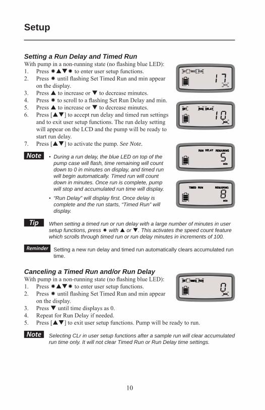
Setting a Run Delay and Timed RunWith pump in a non-running state (no fl ashing blue LED):1. Press to enter user setup functions.2. Press until fl ashing Set Timed Run and min appear
on the display.3. Press to increase or to decrease minutes.4. Press to scroll to a fl ashing Set Run Delay and min.5. Press to increase or to decrease minutes.6. Press [ ] to accept run delay and timed run settings
and to exit user setup functions. The run delay setting will appear on the LCD and the pump will be ready to start run delay.
7. Press [ ] to activate the pump. See Note.
• During a run delay, the blue LED on top of the pump case will fl ash, time remaining will count down to 0 in minutes on display, and timed run will begin automatically. Timed run will count down in minutes. Once run is complete, pump will stop and accumulated run time will display.
• “Run Delay” will display fi rst. Once delay is complete and the run starts, “Timed Run” will display.
When setting a timed run or run delay with a large number of minutes in user setup functions, press with or . This activates the speed count feature which scrolls through timed run or run delay minutes in increments of 100.
Setting a new run delay and timed run automatically clears accumulated run time.
Canceling a Timed Run and/or Run DelayWith pump in a non-running state (no fl ashing blue LED):1. Press to enter user setup functions.2. Press until fl ashing Set Timed Run and min appear
on the display.3. Press until time displays as 0. 4. Repeat for Run Delay if needed.5. Press [ ] to exit user setup functions. Pump will be ready to run.
Selecting CLr in user setup functions after a sample run will clear accumulated run time only. It will not clear Timed Run or Run Delay time settings.
Setup
Note
Tip
Reminder
Note
11
Note
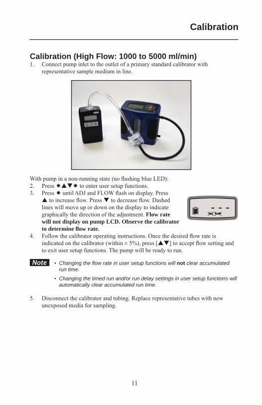
Calibration (High Flow: 1000 to 5000 ml/min)1. Connect pump inlet to the outlet of a primary standard calibrator with
representative sample medium in line.
With pump in a non-running state (no fl ashing blue LED):2. Press to enter user setup functions.3. Press until ADJ and FLOW fl ash on display. Press
to increase fl ow. Press to decrease fl ow. Dashed lines will move up or down on the display to indicate graphically the direction of the adjustment. Flow rate will not display on pump LCD. Observe the calibrator to determine fl ow rate.
4. Follow the calibrator operating instructions. Once the desired fl ow rate is indicated on the calibrator (within ± 5%), press [ ] to accept fl ow setting and to exit user setup functions. The pump will be ready to run.
• Changing the fl ow rate in user setup functions will not clear accumulated run time.
• Changing the timed run and/or run delay settings in user setup functions will automatically clear accumulated run time.
5. Disconnect the calibrator and tubing. Replace representative tubes with new unexposed media for sampling.
Calibration
12
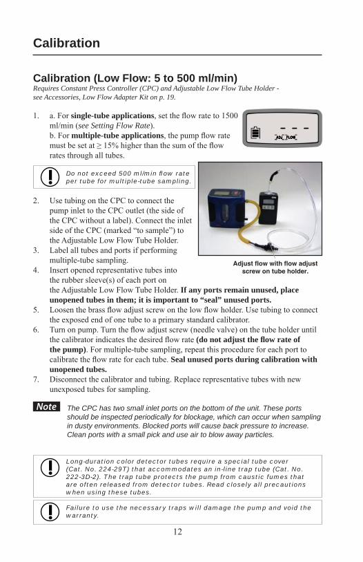
Calibration (Low Flow: 5 to 500 ml/min)Requires Constant Press Controller (CPC) and Adjustable Low Flow Tube Holder - see Accessories, Low Flow Adapter Kit on p. 19.
1. a. For single-tube applications, set the fl ow rate to 1500 ml/min (see Setting Flow Rate).
b. For multiple-tube applications, the pump fl ow rate must be set at ≥ 15% higher than the sum of the fl ow rates through all tubes.
Do not exceed 500 ml/min fl ow rate per tube for multiple-tube sampling.
2. Use tubing on the CPC to connect the pump inlet to the CPC outlet (the side of the CPC without a label). Connect the inlet side of the CPC (marked “to sample”) to the Adjustable Low Flow Tube Holder.
3. Label all tubes and ports if performing multiple-tube sampling.
4. Insert opened representative tubes into the rubber sleeve(s) of each port on the Adjustable Low Flow Tube Holder. If any ports remain unused, place unopened tubes in them; it is important to “seal” unused ports.
5. Loosen the brass fl ow adjust screw on the low fl ow holder. Use tubing to connect the exposed end of one tube to a primary standard calibrator.
6. Turn on pump. Turn the fl ow adjust screw (needle valve) on the tube holder until the calibrator indicates the desired fl ow rate (do not adjust the fl ow rate of the pump). For multiple-tube sampling, repeat this procedure for each port to calibrate the fl ow rate for each tube. Seal unused ports during calibration with unopened tubes.
7. Disconnect the calibrator and tubing. Replace representative tubes with new unexposed tubes for sampling.
The CPC has two small inlet ports on the bottom of the unit. These ports should be inspected periodically for blockage, which can occur when sampling in dusty environments. Blocked ports will cause back pressure to increase. Clean ports with a small pick and use air to blow away particles.
Long-duration color detector tubes require a special tube cover (Cat. No. 224-29T) that accommodates an in-line trap tube (Cat. No. 222-3D-2). The trap tube protects the pump from caustic fumes that are often released from detector tubes. Read closely all precautions when using these tubes.
Failure to use the necessary traps will damage the pump and void the warranty.
Note
Calibration
Adjust fl ow with fl ow adjust screw on tube holder.
13
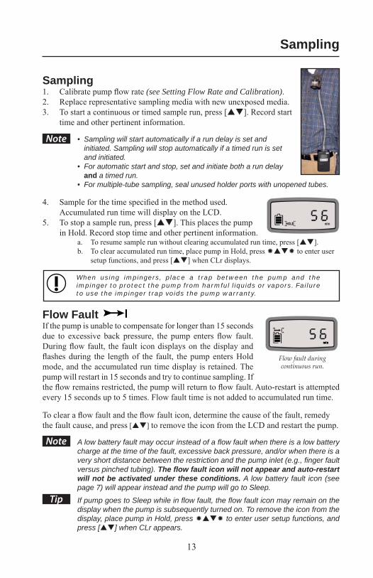
Sampling1. Calibrate pump fl ow rate (see Setting Flow Rate and Calibration).2. Replace representative sampling media with new unexposed media.3. To start a continuous or timed sample run, press [ ]. Record start
time and other pertinent information.
• Sampling will start automatically if a run delay is set and initiated. Sampling will stop automatically if a timed run is set and initiated.
• For automatic start and stop, set and initiate both a run delay and a timed run.
• For multiple-tube sampling, seal unused holder ports with unopened tubes.
4. Sample for the time specifi ed in the method used. Accumulated run time will display on the LCD.
5. To stop a sample run, press [ ]. This places the pump in Hold. Record stop time and other pertinent information.
a. To resume sample run without clearing accumulated run time, press [ ].b. To clear accumulated run time, place pump in Hold, press to enter user
setup functions, and press [ ] when CLr displays.
When using impingers, place a trap between the pump and the impinger to protect the pump from harmful liquids or vapors. Failure to use the impinger trap voids the pump warranty.
Flow FaultIf the pump is unable to compensate for longer than 15 seconds due to excessive back pressure, the pump enters fl ow fault. During fl ow fault, the fault icon displays on the display and fl ashes during the length of the fault, the pump enters Hold mode, and the accumulated run time display is retained. The pump will restart in 15 seconds and try to continue sampling. If the fl ow remains restricted, the pump will return to fl ow fault. Auto-restart is attempted every 15 seconds up to 5 times. Flow fault time is not added to accumulated run time.
To clear a fl ow fault and the fl ow fault icon, determine the cause of the fault, remedy the fault cause, and press [ ] to remove the icon from the LCD and restart the pump.
A low battery fault may occur instead of a fl ow fault when there is a low battery charge at the time of the fault, excessive back pressure, and/or when there is a very short distance between the restriction and the pump inlet (e.g., fi nger fault versus pinched tubing). The fl ow fault icon will not appear and auto-restart will not be activated under these conditions. A low battery fault icon (see page 7) will appear instead and the pump will go to Sleep.
If pump goes to Sleep while in fl ow fault, the fl ow fault icon may remain on the display when the pump is subsequently turned on. To remove the icon from the display, place pump in Hold, press to enter user setup functions, and press [ ] when CLr appears.
Note
Tip
Note
Sampling
Flow fault during continuous run.
14
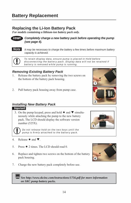
Replacing the Li-Ion Battery PackFor models containing a lithium-ion battery pack only.
Completely charge a new battery pack before operating the pump (see page 4).
It may be necessary to charge the battery a few times before maximum battery capacity is achieved.
To retain display data, ensure pump is placed in Hold before disconnecting the battery pack. Display data will not be retained if battery is removed while pump is running.
Removing Existing Battery Pack1. Release the battery pack by removing the two screws on
the bottom of the battery pack housing.
2. Pull battery pack housing away from pump case.
Installing New Battery Pack
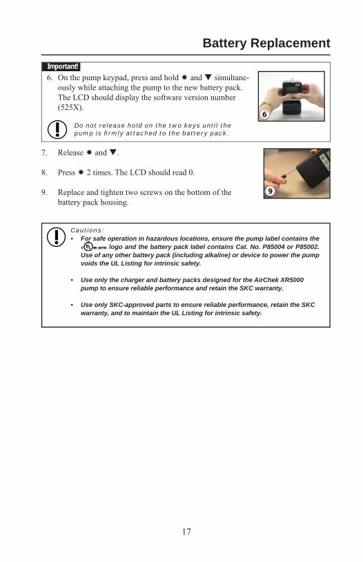
3. On the pump keypad, press and hold and simulta-neously while attaching the pump to the new battery pack. The LCD should display the software version number (525X).
Do not release hold on the two keys until the pump is fi rmly attached to the battery pack.
4. Release and .
5. Press 2 times. The LCD should read 0.
6. Replace and tighten two screws on the bottom of the battery pack housing.
7. Charge the new battery pack completely before use.
Note
Battery Replacement
1
3
6
STOP!
See http://www.skcinc.com/instructions/1756.pdf for more information on SKC pump battery packs.
Important!
15
Cautions:• For safe operation in hazardous locations, ensure the pump label contains the
logo and the battery pack label contains Cat. No. P85004 or P85002. Use of any other battery pack (including alkaline) or device to power the pump voids the UL Listing for intrinsic safety.
• Do not charge or operate pump from charger in hazardous locations.
• Use only the charger and battery packs designed for the AirChek XR5000 pump to ensure reliable performance and retain the SKC warranty.
• Use only SKC-approved parts to ensure reliable performance, retain the SKC warranty, and to maintain the UL Listing for intrinsic safety.
• Tampering with the battery pack or using a repaired or rebuilt battery pack voids the SKC warranty and UL Listing for intrinsic safety.
• Do not open, disassemble, short circuit, crush, incinerate, or expose the battery to fi re or temperatures in excess of 213 F (100 C).
• Use only the SKC-approved charger for this pump. Use of an unapproved charger may damage the battery and pump.
Battery Replacement
16
5
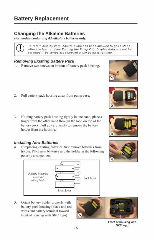
Front of housing with SKC logo
4
Polarity is marked inside the
batt ery holder.
Front layer
Back layer
1
3
Changing the Alkaline BatteriesFor models containing AA alkaline batteries only.
To retain display data, ensure pump has been allowed to go to sleep after the last run (see Turning the Pump Off). Display data will not be retained if batteries are removed while pump is running.
Removing Existing Battery Pack1. Remove two screws on bottom of battery pack housing.
2. Pull battery pack housing away from pump case.
3. Holding battery pack housing tightly in one hand, place a fi nger from the other hand through the loop on top of the battery pack. Pull upward fi rmly to remove the battery holder from the housing.
Installing New Batteries4. If replacing existing batteries, fi rst remove batteries from
holder. Place new batteries into the holder in the following polarity arrangement.
5. Orient battery holder properly with battery pack housing (black and red wires and battery terminal toward front of housing with SKC logo).
Battery Replacement
17
6
9
6. On the pump keypad, press and hold and simultane-ously while attaching the pump to the new battery pack. The LCD should display the software version number (525X).
Do not release hold on the two keys until the pump is fi rmly attached to the battery pack.
7. Release and .
8. Press 2 times. The LCD should read 0.
9. Replace and tighten two screws on the bottom of the battery pack housing.
Cautions:• For safe operation in hazardous locations, ensure the pump label contains the
logo and the battery pack label contains Cat. No. P85004 or P85002. Use of any other battery pack (including alkaline) or device to power the pump voids the UL Listing for intrinsic safety.
• Use only the charger and battery packs designed for the AirChek XR5000 pump to ensure reliable performance and retain the SKC warranty.
• Use only SKC-approved parts to ensure reliable performance, retain the SKC warranty, and to maintain the UL Listing for intrinsic safety.
Battery ReplacementImportant!
18
Note
Service PolicyTo return products to SKC for servicing:
1. Call 800-752-8472 (724-941-9701 for international customers) to obtain a Return Materials Authorization (RMA) number and Product Decontamination Form.
2. Carefully package the product. Mark the RMA number on any correspondence relating to the return and on the outside of the package.
Package product carefully to prevent damage during transit. Include a contact name, phone number, shipping address, RMA number, and a brief description of the problem. For nonwarranty repairs, a purchase order number and billing address are also required. The Service Department will contact nonwarranty customers with an estimate before proceeding with repairs.
Rechargeable lithium-ion batteries for use with SKC sampling pumps have been tested in accordance with the UN Manual of Tests and Criteria and are designated as UN3091. To be exempt from Dangerous Goods Shipping requirements, the box must contain 24 or fewer cells. Therefore, limit any box to be shipped to the following number of pumps:
Leland Legacy Pump - 2 pumpsQuickTake 15 - 12 pumpsQuickTake 30 - 3 pumpsAirChek XR5000 - 6 standard Li-Ion model pumps or 3 high-power Li-Ion model pumpsSee shaded box below.
3. Ship to SKC, freight prepaid, to the following address:SKC Inc.National Service Center863 Valley View RoadEighty Four, PA 15330
SKC Inc. will accept for repair any SKC product that is not contaminated with hazardous materials. Products determined to be contaminated will be returned unserviced.
* Li-Ion Battery Shipment Rechargeable, lithium-Ion batteries for use with SKC sampling pumps have been tested in accordance with the UN
Manual of Tests and Criteria and are designated as UN3091.
For air shipments: Rechargeable lithium-Ion batteries in SKC pumps are subject to the A-45 exemption to the IATA regulations and are
not regulated for air shipments. This information must be written on the shipping document when shipping by air.
For ground shipments: US DOT regulations specify a limit of 24 or fewer battery cells in one shipping box. If you exceed 6 standard Li-Ion
model or 3 high-power Li-Ion model AirChek XR5000 pumps with battery packs in one shipping box, specifi c shipping requirements must be followed. Contact SKC for more information or refer to the regulatory authority in your area.
Note: 5-pack kits of the high-power XR5000 sample pump exceed DOT limitations for ground shipments. Two pumps need to be shipped in a separate box to be exempt OR additional requirements have to be met to place the shipment. Contact SKC for details.
The SKC warranty and UL Listing for intrinsic safety are void if pumps are not repaired by SKC or authorized SKC repair centers. Use only SKC-approved parts to ensure reliable performance, retain the SKC warranty, and maintain the UL Listing for intrinsic safety.
Service
19
Description Cat. No.
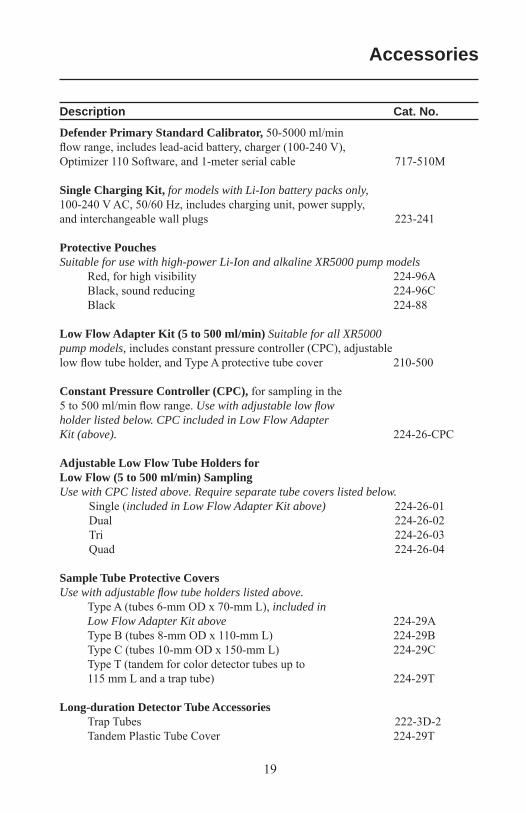
Defender Primary Standard Calibrator, 50-5000 ml/min fl ow range, includes lead-acid battery, charger (100-240 V), Optimizer 110 Software, and 1-meter serial cable 717-510M
Single Charging Kit, for models with Li-Ion battery packs only, 100-240 V AC, 50/60 Hz, includes charging unit, power supply, and interchangeable wall plugs 223-241
Protective PouchesSuitable for use with high-power Li-Ion and alkaline XR5000 pump models Red, for high visibility 224-96A Black, sound reducing 224-96C Black 224-88
Low Flow Adapter Kit (5 to 500 ml/min) Suitable for all XR5000 pump models, includes constant pressure controller (CPC), adjustable low fl ow tube holder, and Type A protective tube cover 210-500
Constant Pressure Controller (CPC), for sampling in the 5 to 500 ml/min fl ow range. Use with adjustable low fl ow holder listed below. CPC included in Low Flow Adapter Kit (above). 224-26-CPC
Adjustable Low Flow Tube Holders for Low Flow (5 to 500 ml/min) SamplingUse with CPC listed above. Require separate tube covers listed below. Single (included in Low Flow Adapter Kit above) 224-26-01 Dual 224-26-02 Tri 224-26-03 Quad 224-26-04
Sample Tube Protective CoversUse with adjustable fl ow tube holders listed above. Type A (tubes 6-mm OD x 70-mm L), included in Low Flow Adapter Kit above 224-29A Type B (tubes 8-mm OD x 110-mm L) 224-29B Type C (tubes 10-mm OD x 150-mm L) 224-29C Type T (tandem for color detector tubes up to 115 mm L and a trap tube) 224-29T
Long-duration Detector Tube Accessories Trap Tubes 222-3D-2 Tandem Plastic Tube Cover 224-29T
Accessories
20
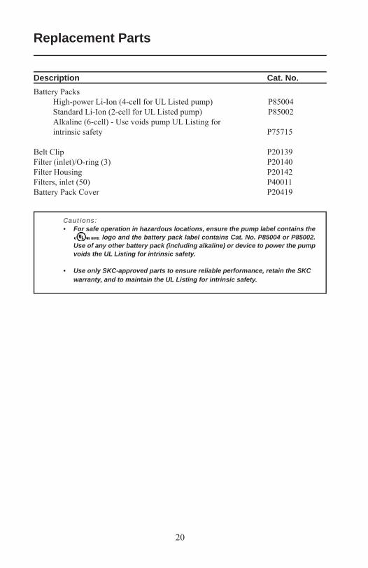
Description Cat. No.Battery Packs High-power Li-Ion (4-cell for UL Listed pump) P85004 Standard Li-Ion (2-cell for UL Listed pump) P85002 Alkaline (6-cell) - Use voids pump UL Listing for intrinsic safety P75715
Belt Clip P20139Filter (inlet)/O-ring (3) P20140Filter Housing P20142Filters, inlet (50) P40011Battery Pack Cover P20419
Cautions:• For safe operation in hazardous locations, ensure the pump label contains the
logo and the battery pack label contains Cat. No. P85004 or P85002. Use of any other battery pack (including alkaline) or device to power the pump voids the UL Listing for intrinsic safety.
• Use only SKC-approved parts to ensure reliable performance, retain the SKC warranty, and to maintain the UL Listing for intrinsic safety.
Replacement Parts
21
SKC INC.LIMITED ONE YEAR WARRANTY
1. SKC warrants that its instruments provided for industrial hygiene, environmental, gas analysis, and safety and health applications are free from defects in workmanship and materials under normal and proper use in accordance with operating instructions provided with said instruments. The term of this warranty begins on the date the instrument is delivered to the buyer and continues for a period of one (1) year. This warranty does not cover claims due to abuse, misuse, neglect, alteration, accident, or use in application for which the instrument was neither designed nor approved by SKC Inc. This warranty does not cover the buyer’s failure to provide for normal maintenance, or improper selection or misapplication. This warranty shall further be void if changes or adjustments to the instrument are made by other than an employee of the seller, or if the operating instructions furnished at the time of installation are not complied with.
2. SKC Inc. hereby disclaims all warranties either expressed or implied, including any implied warranties of merchantability or fi tness for a particular purpose, and neither assumes nor authorizes any other person to assume for it any liability in connection with the sale of these instruments. No description of the goods being sold has been made a part of the basis of the bargain or has created or amounted to an express warranty that the goods will conform to any such description. Buyer shall not be entitled to recover from SKC Inc. any consequential damages, damages to property, damages for loss of use, loss of time, loss of profi ts, loss of income, or other incidental damages. Nor shall buyer be entitled to recover from SKC Inc. any consequential damages resulting from defect of the instrument including, but not limited to, any recovery under section 402A of the Restatement, Second of Torts.
3. This warranty extends only to the original purchaser of the warranted instrument during the term of the warranty. The buyer may be required to present proof of purchase in the form of a paid receipt for the instrument.
4. This warranty covers the instrument purchased and each of its component parts.
5. In the event of a defect, malfunction, or other failure of the instrument not caused by any misuse or damage to the instrument while in possession of the buyer, SKC Inc. will remedy the failure or defect without charge to the buyer. The remedy will consist of service or replacement of the instrument. SKC Inc. may elect refund of the purchase price if unable to provide replacement and repair is not commercially practicable.
6. (a) To obtain performance of any obligation under this warranty, the buyer shall return the instrument, freight prepaid, to SKC Inc., at the following address: SKC Inc., National Service Center 863 Valley View Road Eighty Four, PA 15330 USA (b) To obtain return authorization information or for further information on the warranty performance you may telephone 724-941-9701 at the above address. See Service Policy section in operating manual (if applicable).
7. This warranty shall be construed under the laws of the Commonwealth of Pennsylvania which shall be deemed to be the situs of the contract for purchase of SKC Inc. instruments.
8. No other warranty is given by SKC Inc. in conjunction with this sale.
Form #3755 Rev 0207
Warranty