Embed Size (px)
Citation preview
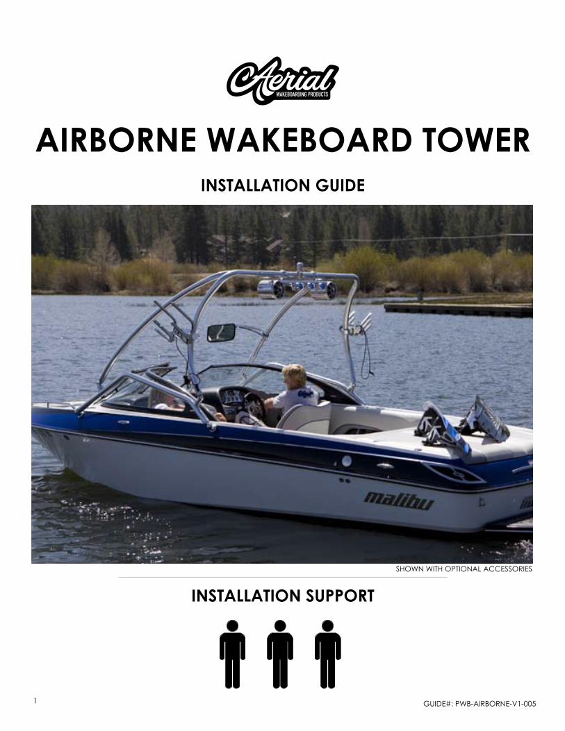
installation guide
GUIDE#: pwb-AIrbornE-v1-0051
airborne WaKeboard toWer
installation suPPort
shown wIth optIonAl AccEssorIEs

GUIDE#: pwb-AIrbornE-v1-0052
This Aerial wakeboard tower fits motor boats with 76-108 inch wide beam widths. • This measurement is taken from the Port to Starboard mounting points. Do not fold the tower without having the top section securely fastened to the side sections with • the fasteners provided.Lubricate the telescopic side section tubes that slide in and out of the top section during instal-• lation. We recommend using a light grease to help the tubes slide together without binding.Do not fold the tower by yourself.• Do not assemble tower on the ground and then try to install it on the boat.• Do not use impact drivers to install any hardware.• Torque set screws to 35ft-lbs • Torque M12 bolts 50 ft-lbs • We recommend using threadlocker on the threads of all fasteners that will not be adjusted • while lowering or raising the tower.Check the top section for burrs before installing side sections to prevent the scratching and • marking of tubes. Aerial does not cover damage caused by burrs during installation.If the area of the deck where the tower will be mounted has a fiberglass thickness of less than • ¼ inch, a backing plate kit must be purchased and installed to provide adequate support.Please leave the foam wrap on the tower until the installing is complete.• Please note that when towing your boat you may notice what appears to be movement in • your tower. It is important to understand that the boat is also moving on the trailer and that this movement can be visually deceiving.
Frequently wash your tower with soap and water.• As required, use Mothers Mag & Aluminum polish to restore your tower to its original finish.•
BE CAREFUL when assembling this product• . We CANNOT be liable for any burring or scratch-ing that may occur when sliding sections in and out of each other.NEVER modify this product in any way.• NEVER climb, stand or ride on this product.• NEVER tow watersport tubes or inflatable’s with this or any other Aerial Wakeboard Tower.• ALWAYS use caution with approaching bridges or overpasses.• ALWAYS inspect this product for loose bolts, fittings or damage before each use.• Always carefully CONSULT the user manual for proper installation, maintenance and usage.• Aerial is not liable for personal injury or property damage from the use of this or any other • Aerial product.
IMPORTANT INFORMATION
cleaning
Warning
GUIDE#: pwb-AIrbornE-v1-0053
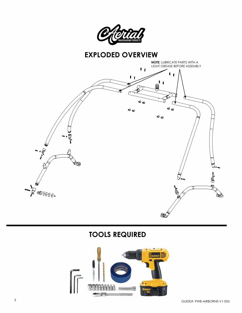
note: lUbrIcAtE pArts wIth A lIGht GrEAsE bEforE AssEmbly
eXPloded oVerVieW
tools reQuired

GUIDE#: pwb-AIrbornE-v1-0054
STNEMMOCYTQNOITPIRCSED# METI
1 2.25" TOWER JOINT - THREADED (INCL. M6 X 12mm BOLT) 4
2 2.25" TOWER JOINT - THRU HOLE (INCL. M6 X 12mm BOLT) 8
4TNUOM KCED3
2 ,1 - SMETI HTIW ESU ROF61TLOB mm04 X 21M4
3 - SMETI HTIW ESU ROF4TLOB mm54 X 21M5
3 - SMETI HTIW ESU ROF4TLOB mm57 & X 21M6
6 ,5 ,4 - SMETI HTIW ESU ROF42REHSAW KCOL GNIRPS 21M7
91 - SMETI HTIW ESU ROF8TLOB DAEH NOTTUB mm57 X 01M8
8 - SMETI HTIW ESU ROF8M10 LOGO NUT9
6 - SMETI HTIW ESU ROF4TUN KCOL NOLYN 21M01
6 - SMETI HTIW ESU ROF4REHSAW TALF NOLYN 21M11
3 - SMETI HTIW ESU ROF4)mm07 = DO( REHSAW TALF NOLYN EGRAL21
3 - SMETI HTIW ESU ROF4)mm07 = DO( REHSAW REBBUR DEVRUC31
3 - SMETI HTIW ESU ROF4)mm07 = DO( REHSAW TALF MUNIMULA EGRAL41
1YEK NELLA 21M51
1YEK NELLA 8M61
1YEK NELLA 6M71
1REKCOLDAERHT81
1EBUT NOITCES POT91
2SLIAR EDIS REWOL02
DRAOBRATS 1 & TROP 12SGEL TNORF12
DRAOBRATS 1 & TROP 12SGEL RAER22
TOWER PACKAGE
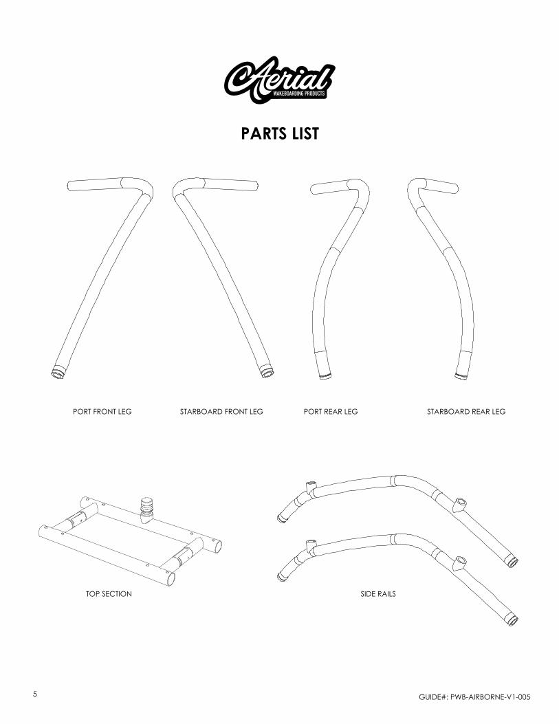
Parts list
GUIDE#: pwb-AIrbornE-v1-0055
Parts list
stArboArD front lEG port rEAr lEG stArboArD rEAr lEGport front lEG
top sEctIon sIDE rAIls
GUIDE#: pwb-AIrbornE-v1-0056
STEP 1
STEP 2
STEP 3
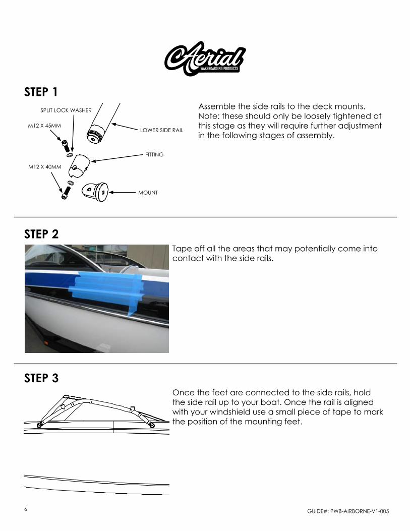
Assemble the side rails to the deck mounts. note: these should only be loosely tightened at this stage as they will require further adjustment in the following stages of assembly.
tape off all the areas that may potentially come into contact with the side rails.
once the feet are connected to the side rails, hold the side rail up to your boat. once the rail is aligned with your windshield use a small piece of tape to mark the position of the mounting feet.
lowEr sIDE rAIlm12 x 45mm
m12 x 40mm
splIt lock wAshEr
moUnt
fIttInG

GUIDE#: pwb-AIrbornE-v1-0057
STEP 2
steP 4
STEP 5
once the desired position is achieved, place one of the large nylon whasers over the piece of tape and trace around it with a permanent marker.
Transferring marks from the other side.this step is very important! After taping the second side of the boat in approximately the same areas as the first side you will need to measure the distance that you marked on the first side of the boat
It is best to take measurements from the back of the boat and mark with blue tape. be sure to measure from the same point on both sides.

GUIDE#: pwb-AIrbornE-v1-0058
STEP 2
STEP 6Drillingonce you have marked your 4 holes, check the underside of the deck for wires.
If necessary, you should move the wires out ofthe way while you drill. we recommend drilling a small pilot hole which will keep the 17/32” drill bit from walk-ing (moving). A small rat tail file can be used to ease the edge and keep the gel coat from chipping. be careful of wires!
A B C
Gelcoat
Fibreglass
SMALL DAIMETER Pilot Hole
17/32” DRILL BIT countersinK(tHrougH gelcoat)

GUIDE#: pwb-AIrbornE-v1-0059
STEP 7
STEP 8measuring from your windshield, check the distance to the side rail to make sure both sides are symmetric.
Install the tower mounts to the boat deck in the order shown in the diagram.Note: in the case where the deck of your boat is less than 1/4” thick, a reinforcing kit is required to thicken and reinforce the deck in the mounting locations.
m12 x 75mm
m12 x 75mm
blAck nylon wAshEr
blAck nylon wAshEr
FLAT DECK - MOUNT ASSEMBLY CURVED DECK - MOUNT ASSEMBLY
moUnt
moUnt
nylon wAshErnylon wAshEr
flAt DEck
cUrvED rUbbEr wAshEr
cUrvED DEck
rEInforcEmEnt rEInforcEmEntrUbbEr wAshEr rUbbEr wAshEr
AlUmInUm bAckInG plAtEAlUmInUm bAckInG plAtE
splIt lock wAshEr splIt lock wAshErnylon lock nUt nylon lock nUt
GUIDE#: pwb-AIrbornE-v1-00510
STEP 8 - CONTINUED...
steP 9
STEP 10
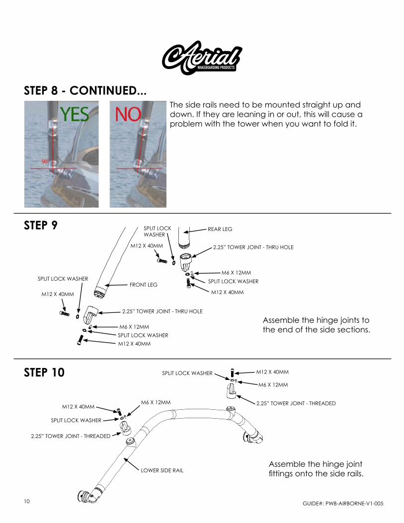
the side rails need to be mounted straight up and down. If they are leaning in or out, this will cause a problem with the tower when you want to fold it.
Assemble the hinge joints to the end of the side sections.
Assemble the hinge joint fittings onto the side rails.
m12 x 40mm
m12 x 40mm
m12 x 40mm
m12 x 40mm
m6 x 12mm
m6 x 12mm
splIt lock wAshEr
splIt lock wAshEr
splIt lockwAshEr
splIt lock wAshEr
2.25” towEr joInt - thrU holE
2.25” towEr joInt - thrU holE
front lEG
rEAr lEG
lowEr sIDE rAIl
m6 x 12mm
m6 x 12mm
splIt lock wAshEr
splIt lock wAshEr
2.25” towEr joInt - thrEADED
2.25” towEr joInt - thrEADEDm12 x 40mm
m12 x 40mm
GUIDE#: pwb-AIrbornE-v1-00511
STEP 2
STEP 11
STEP 12
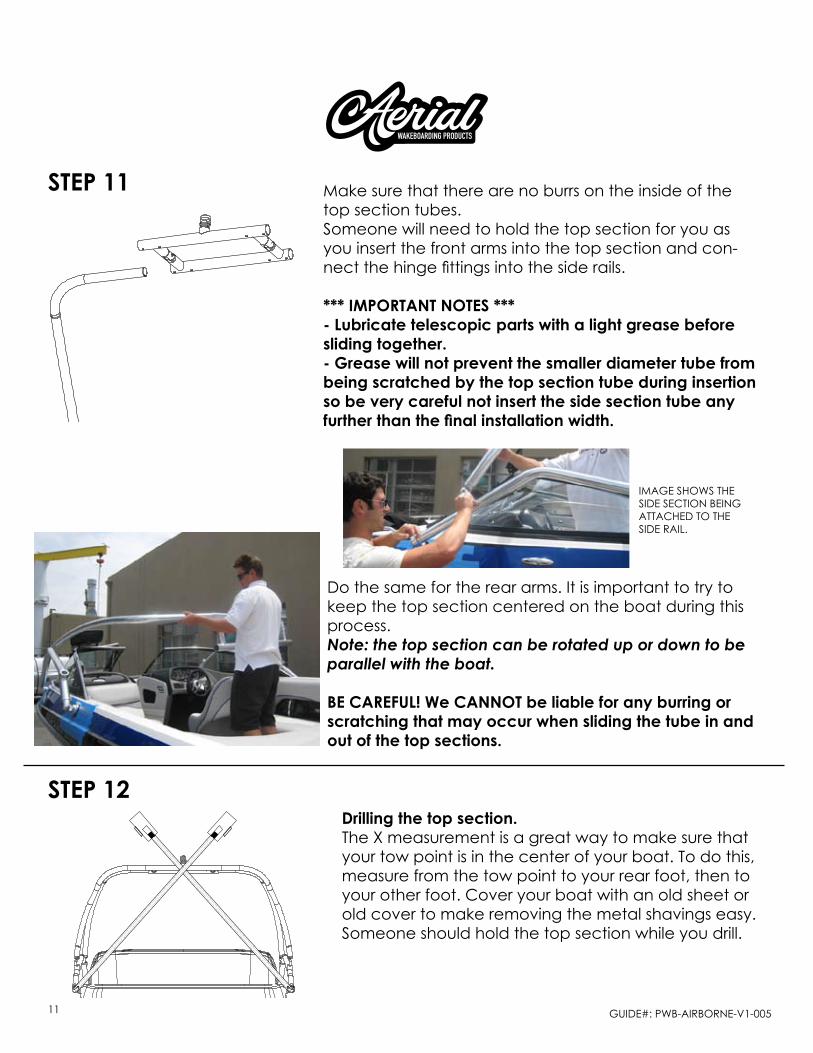
make sure that there are no burrs on the inside of the top section tubes. someone will need to hold the top section for you as you insert the front arms into the top section and con-nect the hinge fittings into the side rails.
*** IMPORTANT NOTES ***- Lubricate telescopic parts with a light grease before sliding together.- Grease will not prevent the smaller diameter tube from being scratched by the top section tube during insertion so be very careful not insert the side section tube any further than the final installation width.
Do the same for the rear arms. It is important to try to keep the top section centered on the boat during this process.Note: the top section can be rotated up or down to be parallel with the boat.
BE CAREFUL! We CANNOT be liable for any burring or scratching that may occur when sliding the tube in and out of the top sections.
Drilling the top section. the x measurement is a great way to make sure that your tow point is in the center of your boat. to do this, measure from the tow point to your rear foot, then to your other foot. cover your boat with an old sheet or old cover to make removing the metal shavings easy. someone should hold the top section while you drill.
ImAGE shows thE sIDE sEctIon bEInG AttAchED to thE sIDE rAIl.
GUIDE#: pwb-AIrbornE-v1-00512
STEP 12 - CONTINUED...
STEP 13
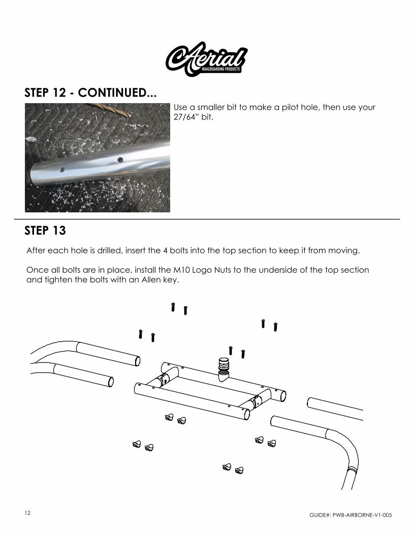
Use a smaller bit to make a pilot hole, then use your 27/64” bit.
After each hole is drilled, insert the 4 bolts into the top section to keep it from moving.
once all bolts are in place, install the m10 logo nuts to the underside of the top section and tighten the bolts with an Allen key.

GUIDE#: pwb-AIrbornE-v1-00513
STEP 15
Lowering the Tower. loosen the rear tower hinges about 1/4 turn. the front tower hinges need to be disconnected with the help of an Allen key to allow the tower to fold back.once the tower is folded back, remove the 2 Allen bolts from the top section hinge which will allow the arms to fold down for storage.
STEP 14 - LOCKING ThE ROTATING FITTINGS
once you are happy with your tower installation and all of the fittings are lined up to allow the tower to fold and function correctly it will then be important to firmly lock the rotating fittings in place to prevent any unwanted rota-tion or loosening. to do this the m12 x 40mm bolts that run through the center of the fittings will need to be firmly tight-ened. next, the pre-instaleld m6 x 10mm fasteners found in the fittings will then need to be firmly tightened with an Allen key. we recommend using threadlocker during this step.
m6 x 12mm
GUIDE#: pwb-AIrbornE-v1-00514
Questions?
www.aerialwakeboarding.com
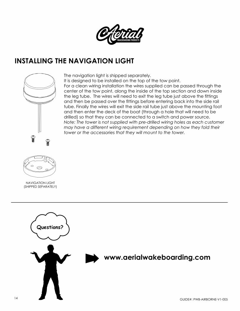
installing tHe naVigation ligHt
the navigation light is shipped separately.It is designed to be installed on the top of the tow point.for a clean wiring installation the wires supplied can be passed through the center of the tow point, along the inside of the top section and down inside the leg tube. The wires will need to exit the leg tube just above the fittings and then be passed over the fittings before entering back into the side rail tube. finally the wires will exit the side rail tube just above the mounting foot and then enter the deck of the boat (through a hole that will need to be drilled) so that they can be connected to a switch and power source.Note: The tower is not supplied with pre-drilled wiring holes as each customer may have a different wiring requirement depending on how they fold their tower or the accessories that they will mount to the tower.
nAvIGAtIon lIGht (shIppED sEpArAtEly)