Embed Size (px)
Citation preview

To b e l e f t w i t h t h e u s e r
www.glow-worm.co.uk
Instructions for Use
www.glow-worm.co.uk
Air / Water Heat PumpEnvirosorb

www.glow-worm.co.uk2
Customer service call: 01773 828100 Technical helpline: 01773 828300General and Sales enquiries Tel: 01773 824639 Fax: 01773 820569
• Do not insert fingers or objects in the air inlets and outlets while the unit is operating as the high speed fan can cause injuries.
• Do not cover the heat pump.
• Do not use water to clean the unit, refer to 2.1.
• Disconnect the power source when cleaning the unit, this will avoid the risk of short-circuiting or injury.
• Do not dismantle the heat pump, exposing the fan or internal parts can be very dangerous.
• This appliance contains metal parts (components) and care should be taken when handling and cleaning, with particular regard to edges.
• Under no circumstances must the User interfere with or adjust sealed parts.
WARNING
Benchmark places responsibilities on both manufacturers and installers. The purpose is to ensure that customers are provided with the correct equipment for their needs, that it is installed, commissioned and serviced in accordance with the manufacturer’s instructions by competent persons and that it meets the requirements of the appropriate Building Regulations. The Benchmark Checklist can be used to demonstrate compliance with Building Regulations and should be provided to the customer for future reference.Installers are required to carry out installation, commissioning and servicing work in accordance with the Benchmark Code of Practice which is available from the Heating and Hotwater Industry Council who manage and promote the Scheme.Visit www.centralheating.co.uk for more information.

www.glow-worm.co.uk3
Envirosorb 8Envirosorb 10Envirosorb 14
1541
0
30
psi
bar
20
40
10
0
4
1
3
2
50
58
www.glow-worm.co.uk4
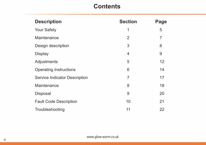
Description Section PageYour Safety 1 5
Maintenance 2 7
Design description 3 8
Display 4 9
Adjustments 5 12
Operating Instructions 6 14
Service Indicator Description 7 17
Maintenance 8 18
Disposal 9 20
Fault Code Description 10 21
Troubleshooting 11 22
Contents

www.glow-worm.co.uk5
1.1 SAFETY WARNINGSThe appliance MUST be earthed.
The appliance MUST be connected to a separately fused sub-circuit protected by a correctly sized circuit breaker and earth leakage protection.
Connection of the whole electrical system of the appliance, including any heating controls, to the electrical supply must be through one common isolator.
In your own interests and that of safety, it is the Law that ALL appliances have been installed by a competent person and used in accordance with the Regulations and Standards for refrigeration, electrical, hydraulic and mechanical equipment prevailing in relation to the location of such installations.
This appliance has been designed and manufactured for heating and circulating water in a central heating system. The use thereof for other domestic or industrial purposes shall be the exclusive responsibility of the persons designing, managing, installing or using them in that way. As part of its policy for ongoing improvments of its products, Glow-worm reserves the right to modify these specifications without prior notice. Glow-worm cannot foresee all the possible circumstances that could pose a potential risk.
Prior to handling, installing, starting up, using or performing maintenance on the appliance, the persons assigned to perform these tasks should be familiar with all the instructions and recommendations set forth in the appliances installation manual and in the user manual.
1 Your safety
In the event that the heat pump is removed and subsequently reinstalled, its proper reinstallation must be adequately verified. Otherwise, water or refrigerant leakage could occur, as well as short-circuiting or even fire.
Do not handle the appliance with wet or damp hands as this would cause a risk of electrocution.
The appliance must not be installed near a heat source, flammable or corrosive materials or the air vent from an adjoining building.
Disconnect the power source when cleaning the appliance. This will avoid the risk of short-circuiting or injury. Connect the earth cable to the right connection point (not to the gas pipe, water pipe, neutral cable or telephone line). Incorrect earthing may cause electrical risk. Install the correct electrical protection and correct size and rated cable to ensure electrical safety.
Do not place the equipment in areas open to insecticides or pesticides. Poisonous chemicals may settle in the appliance and harm the health of persons with allergies to chemical substances.
No part of this manual can be reproduced without written consent. This appliance contains R410a refrigerant which is covered by the F-gas regulations. Periodic inspections for refrigerant leaks may be required depending on current European and local legislation.
For further information, please contact your nearest Glow-worm distributor.NOTE: Keep the manuals throughout the service life of the appliance. The information relating to this unit is divided between two manuals: installation manual and user manual.
www.glow-worm.co.uk6
1.2 Testing and CertificationThis appliance is certificated for performance and safety in use.
It is important that no alteration is made to the appliance unless approved, in writing, by Glow-worm.
Any alteration not approved by Glow-worm, could invalidate the certification, appliance warranty and may also infringe the current issue of the statutory requirements.
1.3 CE MarkThe CE mark on this appliance shows compliance with:
1. Directive 97/23/EEC on pressure equipment
2. Directive 73/23/EEC on the harmonisation of the Laws of the Member States relating to electrical equipment designed for use within certain voltage limits.
3. Directive 89/336/EEC on the approximation of the Laws of the Member States relating to electromagnetic compatibility.
1.4 General NoteServicing/maintenance should be carried out by a competent person in accordance with the rules in force in the countries of destination.
1.5 ServicingThis appliance should be serviced regularly to optimise its safety, efficiency and performance.
To ensure the continued efficient and safe operation of the
appliance it is recommended that it is checked and serviced at regular intervals. The frequency of servicing will depend upon the site conditions and usage, but in general, once a year should be enough.
To obtain service, please call your installer or Glow-worm’s own service organisation using the telephone number on the inside front cover of this booklet.
1.6 Spare PartsREMEMBER: When replacing a part on this appliance, use only spare parts that you can be assured conform to the safety and performance specification that we require. Do not use reconditioned or copy parts that have not been clearly authorised by Glow-worm.
If replacement parts are required contact Glow-worm’s own service organisation using the telephone number on the inside front cover of this booklet.
Please quote the name and model of the appliance. The name and model badge is on the outer case above the hydraulic connections.
If in doubt seek advice from Glow-worm’s own service organisation using the telephone number on the inside front cover of this booklet.
1 Your safety

www.glow-worm.co.uk7
2.1 CLEANING THE UNITIMPORTANT: Before cleaning, ensure that the Envirosorb is switched off.
Wipe the outer part of the appliance with a dry cloth.
Occasionally remove dust leaves and other build up from the external heat exchanger inlet surface.
Occasionally check the base of the Envirosorb to ensure to the drain pan is clean and there is no build up of corrosion.
DANGER: of injury and physical damage.
• Do not dismantle the appliance outlet. Exposing the fan can be very dangerous.
DANGER: Danger of electric shock.
• Do not clean the appliance with water.
• Do not use petrol, solvents or polishes when cleaning the appliance.
2 Maintenance
www.glow-worm.co.uk8
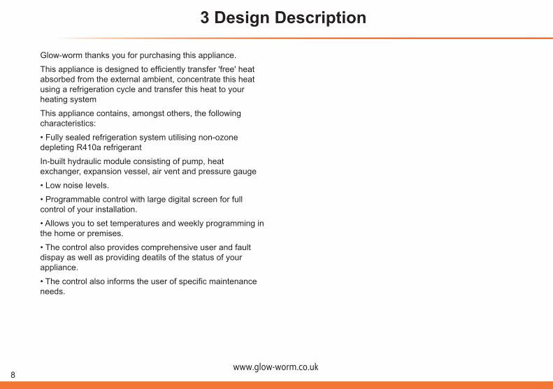
3 Design Description
Glow-worm thanks you for purchasing this appliance.
This appliance is designed to efficiently transfer 'free' heat absorbed from the external ambient, concentrate this heat using a refrigeration cycle and transfer this heat to your heating system
This appliance contains, amongst others, the following characteristics:
• Fully sealed refrigeration system utilising non-ozone depleting R410a refrigerant
In-built hydraulic module consisting of pump, heat exchanger, expansion vessel, air vent and pressure gauge
• Low noise levels.
• Programmable control with large digital screen for full control of your installation.
• Allows you to set temperatures and weekly programming in the home or premises.
• The control also provides comprehensive user and fault dispay as well as providing deatils of the status of your appliance.
• The control also informs the user of specific maintenance needs.
www.glow-worm.co.uk9
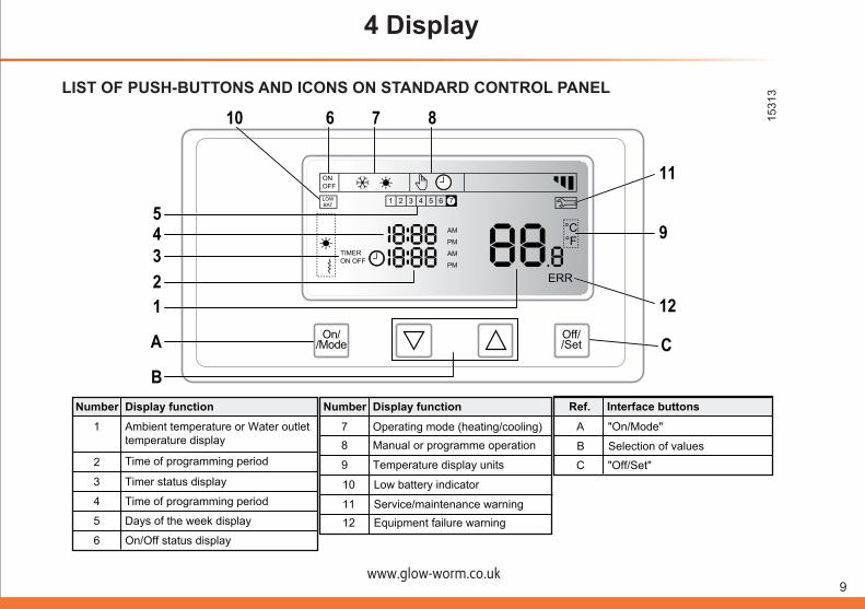
4 Display
LIST OF PUSH-BUTTONS AND ICONS ON STANDARD CONTROL PANEL
°C °F
ERR
AM
PM
AM
PM
ON OFF
1 2 3 4 5 6 7 LOW BAT
TIMER ON OFF
10 6 7 8
A
B
C
54321
11
9
12On/
/ModeOff//Set
Display functionNumber
1
2
Ambient temperature or Water outlettemperature display
Time of programming period
3 Timer status display
4 Time of programming period
5 Days of the week display
6 On/Off status display
Display functionNumber
7 Operating mode (heating/cooling)8 Manual or programme operation
9 Temperature display units C "Off/Set"
B Selection of values
Interface buttonsRef.
A "On/Mode"
10 Low battery indicator
11 Service/maintenance warning12 Equipment failure warning
1531
3

www.glow-worm.co.uk10
4 Display
4.1 USING THE PUSH-BUTTONS
Name FunctionNumber
A
B
For switching the appliance on and to navigate through different functions by pressing several times
"On/Mode"
"Off/Set"C
For lowering and raising the values of aparameter respectively
▲ and ▼
For switching off the appliance or validating input
4.2 WARNING SYMBOLS
Equipment shut down warning, ERR
°C °F
ERR
AM
PM
AM
PM
6 7
12Off//Set
The control can show a series of alpha numeric error codes in the event of specific situations occurring. They result in the system shut down.
The control will show the ERR indication and a code which indicates the error type according to the fault code description table, refer to section 9.
1531
5
1531
6

www.glow-worm.co.uk11
4 Display
4.3 EQUIPMENT STATUS DISPLAY
On//Mode
Off//Set
AM
PM
1 2 3 4 5 6 7
°C °F
LOW BAT
ON OFF
TIMER ON OFF
If the equipment is switched off, "OFF" is shown: Press "On/Mode" once and the equipment will switch on.
Note: There may be a short delay before the unit starts
If the equipment is switched on, "ON" is shown: Press "Off/Set" once and the equipment will switch off.
4.4 OPERATION DISPLAY On/
/Mode
Off//Set
AM
PM
1 2 3 4 5 6 7
°C °F
LOW BAT
ON OFF
TIMER ON OFF
On//Mode
Off//Set
AM
PM
1 2 3 4 5 6 7
°C °F
LOW BAT
ON OFF
TIMER ON OFF
On//Mode
Off//Set
AM
PM
1 2 3 4 5 6 7
°C °F
LOW BAT
ON OFF
TIMER ON OFF
Manual Mode - unit operates continuously or timer delay
on or off using the delay timer
On//Mode
Off//Set
AM
PM
1 2 3 4 5 6 7
°C °F
LOW BAT
ON OFF
TIMER ON OFF
Programmable Mode - unit operates only for the user
set timed periods
Press the On//Mode
Off//Set
AM
PM
1 2 3 4 5 6 7
°C °F
LOW BAT
ON OFF
TIMER ON OFF
key several times until the
On//Mode
Off//Set
AM
PM
1 2 3 4 5 6 7
°C °F
LOW BAT
ON OFF
TIMER ON OFF
On//Mode
Off//Set
AM
PM
1 2 3 4 5 6 7
°C °F
LOW BAT
ON OFF
TIMER ON OFF
symbol blinks. Select the desired function using the▲and▼push-buttons.
Confirm using the
On//Mode
Off//Set
AM
PM
1 2 3 4 5 6 7
°C °F
LOW BAT
ON OFF
TIMER ON OFF
key or go to the next function using
the On//Mode
Off//Set
AM
PM
1 2 3 4 5 6 7
°C °F
LOW BAT
ON OFF
TIMER ON OFF
key.
The unit can be programmed to set several operating time slots so it is enabled and disabled automatically.
NOTE: To set programmer, see section 6.
www.glow-worm.co.uk12
5 Adjustments
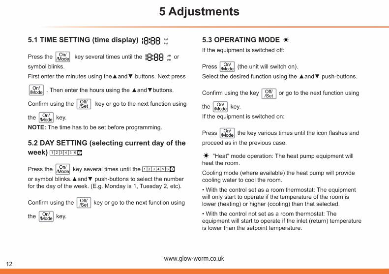
5.1 TIME SETTING (time display)
On//Mode
Off//Set
AM
PM
1 2 3 4 5 6 7
°C °F
LOW BAT
ON OFF
TIMER ON OFF
Press the On//Mode
Off//Set
AM
PM
1 2 3 4 5 6 7
°C °F
LOW BAT
ON OFF
TIMER ON OFF
key several times until the
On//Mode
Off//Set
AM
PM
1 2 3 4 5 6 7
°C °F
LOW BAT
ON OFF
TIMER ON OFF
or
symbol blinks.
First enter the minutes using the▲and▼ buttons. Next press
On//Mode
Off//Set
AM
PM
1 2 3 4 5 6 7
°C °F
LOW BAT
ON OFF
TIMER ON OFF
. Then enter the hours using the ▲and▼buttons.
Confirm using the
On//Mode
Off//Set
AM
PM
1 2 3 4 5 6 7
°C °F
LOW BAT
ON OFF
TIMER ON OFF
key or go to the next function using
the On//Mode
Off//Set
AM
PM
1 2 3 4 5 6 7
°C °F
LOW BAT
ON OFF
TIMER ON OFF
key.
NOTE: The time has to be set before programming.
5.2 DAY SETTING (selecting current day of the week)
On//Mode
Off//Set
AM
PM
1 2 3 4 5 6 7
°C °F
LOW BAT
ON OFF
TIMER ON OFF
Press the On//Mode
Off//Set
AM
PM
1 2 3 4 5 6 7
°C °F
LOW BAT
ON OFF
TIMER ON OFF
key several times until the
On//Mode
Off//Set
AM
PM
1 2 3 4 5 6 7
°C °F
LOW BAT
ON OFF
TIMER ON OFF
or symbol blinks.▲and▼ push-buttons to select the number for the day of the week. (E.g. Monday is 1, Tuesday 2, etc).
Confirm using the
On//Mode
Off//Set
AM
PM
1 2 3 4 5 6 7
°C °F
LOW BAT
ON OFF
TIMER ON OFF
key or go to the next function using
the On//Mode
Off//Set
AM
PM
1 2 3 4 5 6 7
°C °F
LOW BAT
ON OFF
TIMER ON OFF
key.
5.3 OPERATING MODE
On//Mode
Off//Set
AM
PM
1 2 3 4 5 6 7
°C °F
LOW BAT
ON OFF
TIMER ON OFF
If the equipment is switched off:
Press On//Mode
Off//Set
AM
PM
1 2 3 4 5 6 7
°C °F
LOW BAT
ON OFF
TIMER ON OFF
(the unit will switch on).
Select the desired function using the ▲and▼ push-buttons.
Confirm using the key
On//Mode
Off//Set
AM
PM
1 2 3 4 5 6 7
°C °F
LOW BAT
ON OFF
TIMER ON OFF
or go to the next function using
the On//Mode
Off//Set
AM
PM
1 2 3 4 5 6 7
°C °F
LOW BAT
ON OFF
TIMER ON OFF
key.
If the equipment is switched on:
Press On//Mode
Off//Set
AM
PM
1 2 3 4 5 6 7
°C °F
LOW BAT
ON OFF
TIMER ON OFF
the key various times until the icon flashes and
proceed as in the previous case.
On//Mode
Off//Set
AM
PM
1 2 3 4 5 6 7
°C °F
LOW BAT
ON OFF
TIMER ON OFF
"Heat" mode operation: The heat pump equipment will heat the room.
Cooling mode (where available) the heat pump will provide cooling water to cool the room.
• With the control set as a room thermostat: The equipment will only start to operate if the temperature of the room is lower (heating) or higher (cooling) than that selected.
• With the control not set as a room thermostat: The equipment will start to operate if the inlet (return) temperature is lower than the setpoint temperature.
www.glow-worm.co.uk13
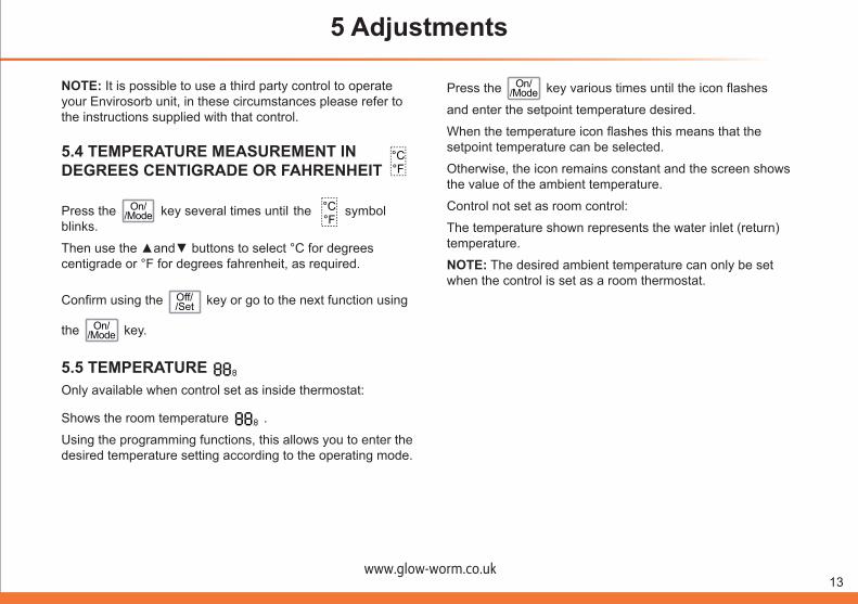
NOTE: It is possible to use a third party control to operate your Envirosorb unit, in these circumstances please refer to the instructions supplied with that control.
5.4 TEMPERATURE MEASUREMENT IN DEGREES CENTIGRADE OR FAHRENHEIT
Press the On//Mode
Off//Set
AM
PM
1 2 3 4 5 6 7
°C °F
LOW BAT
ON OFF
TIMER ON OFF
key several times until the
On//Mode
Off//Set
AM
PM
1 2 3 4 5 6 7
°C °F
LOW BAT
ON OFF
TIMER ON OFF
symbol blinks.
Then use the ▲and▼ buttons to select °C for degrees centigrade or °F for degrees fahrenheit, as required.
Confirm using the
On//Mode
Off//Set
AM
PM
1 2 3 4 5 6 7
°C °F
LOW BAT
ON OFF
TIMER ON OFF
key or go to the next function using
the On//Mode
Off//Set
AM
PM
1 2 3 4 5 6 7
°C °F
LOW BAT
ON OFF
TIMER ON OFF
key.
5.5 TEMPERATURE
On//Mode
Off//Set
AM
PM
1 2 3 4 5 6 7
°C °F
LOW BAT
ON OFF
TIMER ON OFF
Only available when control set as inside thermostat:
Shows the room temperature
On//Mode
Off//Set
AM
PM
1 2 3 4 5 6 7
°C °F
LOW BAT
ON OFF
TIMER ON OFF
.
Using the programming functions, this allows you to enter the desired temperature setting according to the operating mode.
5 Adjustments
Press the On//Mode
Off//Set
AM
PM
1 2 3 4 5 6 7
°C °F
LOW BAT
ON OFF
TIMER ON OFF
key various times until the icon flashes
and enter the setpoint temperature desired.
When the temperature icon flashes this means that the setpoint temperature can be selected.
Otherwise, the icon remains constant and the screen shows the value of the ambient temperature.
Control not set as room control:
The temperature shown represents the water inlet (return)temperature.
NOTE: The desired ambient temperature can only be set when the control is set as a room thermostat.
On//Mode
Off//Set
AM
PM
1 2 3 4 5 6 7
°C °F
LOW BAT
ON OFF
TIMER ON OFF
www.glow-worm.co.uk14
6 Operating instructions
6.1 ADVANCE MODE On/
/Mode
Off//Set
AM
PM
1 2 3 4 5 6 7
°C °F
LOW BAT
ON OFF
TIMER ON OFF
On//Mode
Off//Set
AM
PM
1 2 3 4 5 6 7
°C °F
LOW BAT
ON OFF
TIMER ON OFF
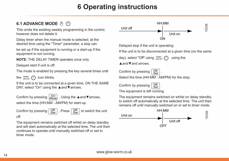
This omits the existing weekly programming in the control, however does not delete it.
Delay timer when the manual mode is selected, at the desired time using the "Timer" parameter, a stop can
be set up if the equipment is running or a start-up if the equipment is not running.
NOTE: THE DELAY TIMER operates once only
Delayed start if unit is off:
The mode is enabled by pressing the key several times until
the
On//Mode
Off//Set
AM
PM
1 2 3 4 5 6 7
°C °F
LOW BAT
ON OFF
TIMER ON OFF icon blinks.
If the unit is to be connected at a given time, ON THE SAME DAY, select "On" using the ▲and▼arrows.
Confirm by pressing On//Mode
Off//Set
AM
PM
1 2 3 4 5 6 7
°C °F
LOW BAT
ON OFF
TIMER ON OFF
. Using the ▲and▼arrows,
select the time (HH:MM - AM/PM) for start-up.
Confirm by pressing
On//Mode
Off//Set
AM
PM
1 2 3 4 5 6 7
°C °F
LOW BAT
ON OFF
TIMER ON OFF
. Press
On//Mode
Off//Set
AM
PM
1 2 3 4 5 6 7
°C °F
LOW BAT
ON OFF
TIMER ON OFF
to switch the unit
off.
The equipment remains switched off whilst on delay standby and will start automatically at the selected time. The unit then continues to operate until manually switched off or set to timer mode.
Unit offUnit on
ON
HH:MM
Delayed stop if the unit is operating:
If the unit is to be disconnected at a given time (on the same
day), select "Off" using
On//Mode
Off//Set
AM
PM
1 2 3 4 5 6 7
°C °F
LOW BAT
ON OFF
TIMER ON OFF using the
▲and▼and arrows.
Confirm by pressing
On//Mode
Off//Set
AM
PM
1 2 3 4 5 6 7
°C °F
LOW BAT
ON OFF
TIMER ON OFF
.
Select the time (HH:MM - AM/PM) for the stop.
Confirm by pressing
On//Mode
Off//Set
AM
PM
1 2 3 4 5 6 7
°C °F
LOW BAT
ON OFF
TIMER ON OFF
.
The equipment is left running.
The equipment remains switched on whilst on delay standby to switch off automatically at the selected time. The unit then remains off until manually switched on or set to timer mode.
Unit onUnit off
OFF
HH:MM
1533
915
338

www.glow-worm.co.uk15
6 Operating instructions
6.2 PROGRAMMABLE MODE
On//Mode
Off//Set
AM
PM
1 2 3 4 5 6 7
°C °F
LOW BAT
ON OFF
TIMER ON OFF
For temperature control the control must be set as a room thermostat.
The contol responds to the time and weekly programming as set. To set up programming, follow the steps below:
1st step:
Press On//Mode
Off//Set
AM
PM
1 2 3 4 5 6 7
°C °F
LOW BAT
ON OFF
TIMER ON OFF
until the day of the week that you want to
program blinks.
2nd step:Select the days for which the same programming is going to be carried out.
Example: 1st block: Working days M-T-W-T-F correspond to the numbers 1-2-3-4-5
Use the▲and▼arrows to select block days 1, 2, 3, 4, 5.
On//Mode
Off//Set
AM
PM
1 2 3 4 5 6 7
°C °F
LOW BAT
ON OFF
TIMER ON OFF
3rd step:
Press On//Mode
Off//Set
AM
PM
1 2 3 4 5 6 7
°C °F
LOW BAT
ON OFF
TIMER ON OFF
The start-up time flashes. The start-up time
must ALWAYS be earlier than the stop time.
Using the▲and▼arrows select the start-up time (for example 7:00 AM)
4th step:
Press On//Mode
Off//Set
AM
PM
1 2 3 4 5 6 7
°C °F
LOW BAT
ON OFF
TIMER ON OFF
The stop time blinks.
Using the▲and▼arrows select the stop time (for example 13:00 PM)
Press On//Mode
Off//Set
AM
PM
1 2 3 4 5 6 7
°C °F
LOW BAT
ON OFF
TIMER ON OFF
to confirm.
5th step:Now select the desired temperature (for example 23.0°C) using the▲and▼arrows. The operating mode will be set later
Press On//Mode
Off//Set
AM
PM
1 2 3 4 5 6 7
°C °F
LOW BAT
ON OFF
TIMER ON OFF
to confirm.
6th stepGeneration of another programming section within the day block.
Steps 1 to 5 are repeated.
The next programming period must come after the first one.
For example: Start-up: 16:00 PM
Stop: 20:00 PM
Temperature: 25°C
NOTE: A different temperature can be selected in each time section.
www.glow-worm.co.uk16
7th step. End program:To conclude the programming of the day block, a time period which shows the same start and end time must be entered.
Press On//Mode
Off//Set
AM
PM
1 2 3 4 5 6 7
°C °F
LOW BAT
ON OFF
TIMER ON OFF
to confirm.
8th step. New Block:Generation of another block of days:
Having confirmed the end of the first block of days, the next block is started. These must be different days to the previous setting.
Example:Programming 1: Monday to Friday from 7:00 to 13:00 and from 16:00 to 20:00
Programming 2: Saturday from 10:00 to 14:00 and from 17:00 to 22:00
Programming 3: Sunday from 10:00 to 14:00
NOTE: In the programmable mode, the operating mode will
be the enabled for
On//Mode
Off//Set
AM
PM
1 2 3 4 5 6 7
°C °F
LOW BAT
ON OFF
TIMER ON OFF
heat or where fitted, cool. The unit will only operate for ambient temperature values above the setpoint values.
6 Operating instructions
www.glow-worm.co.uk17
7 Service Indicator Description
1533
3
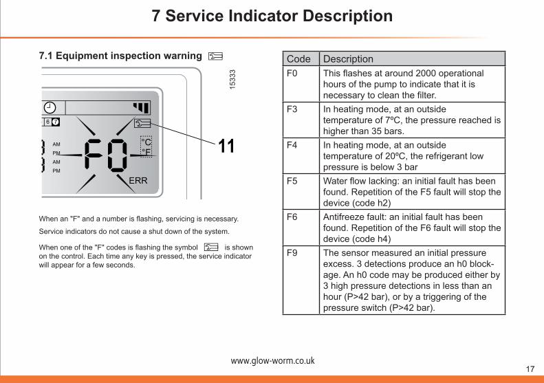
7.1 Equipment inspection warning
On//Mode
Off//Set
AM
PM
1 2 3 4 5 6 7
°C °F
LOW BAT
ON OFF
TIMER ON OFF
°C °F
ERR
AM
PM
AM
PM
ON OFF
1 2 3 4 5 6 7 LOW BAT
TIMER ON OFF
11
On//Mode
Off//Set
When an "F" and a number is flashing, servicing is necessary.
Service indicators do not cause a shut down of the system.
When one of the "F" codes is flashing the symbol
On//Mode
Off//Set
AM
PM
1 2 3 4 5 6 7
°C °F
LOW BAT
ON OFF
TIMER ON OFF
is shown on the control. Each time any key is pressed, the service indicator will appear for a few seconds.
Code DescriptionF0 This flashes at around 2000 operational
hours of the pump to indicate that it is necessary to clean the filter.
F3 In heating mode, at an outsidetemperature of 7ºC, the pressure reached is higher than 35 bars.
F4 In heating mode, at an outsidetemperature of 20ºC, the refrigerant low pressure is below 3 bar
F5 Water flow lacking: an initial fault has been found. Repetition of the F5 fault will stop the device (code h2)
F6 Antifreeze fault: an initial fault has been found. Repetition of the F6 fault will stop the device (code h4)
F9 The sensor measured an initial pressure excess. 3 detections produce an h0 block-age. An h0 code may be produced either by 3 high pressure detections in less than an hour (P>42 bar), or by a triggering of the pressure switch (P>42 bar).
www.glow-worm.co.uk18
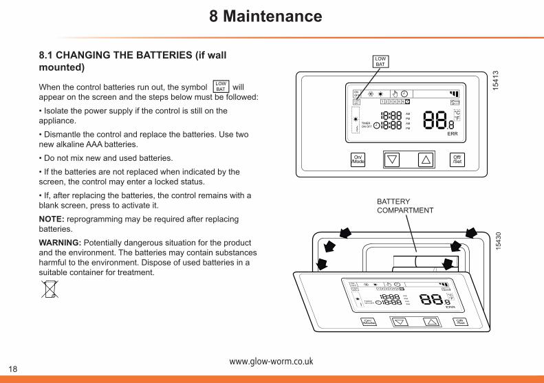
8.1 CHANGING THE BATTERIES (if wall mounted)
When the control batteries run out, the symbol
On//Mode
Off//Set
AM
PM
1 2 3 4 5 6 7
°C °F
LOW BAT
ON OFF
TIMER ON OFF
will appear on the screen and the steps below must be followed:
• Isolate the power supply if the control is still on the appliance.
• Dismantle the control and replace the batteries. Use two new alkaline AAA batteries.
• Do not mix new and used batteries.
• If the batteries are not replaced when indicated by the screen, the control may enter a locked status.
• If, after replacing the batteries, the control remains with a blank screen, press to activate it.
NOTE: reprogramming may be required after replacing batteries.
WARNING: Potentially dangerous situation for the product and the environment. The batteries may contain substances harmful to the environment. Dispose of used batteries in a suitable container for treatment.
On//Mode
Off//Set
AM
PM
1 2 3 4 5 6 7
°C °F
LOW BAT
ON OFF
TIMER ON OFF
8 Maintenance
1541
315
430
On//Mode
Off//Set
AM
PM
1 2 3 4 5 6 7
°C °F
LOW BAT
ON OFF
TIMER ON OFF
°C °F
ERR
AM
PM
AM
PM
ON OFF
1 2 3 4 5 6 7 LOW BAT
TIMER ON OFF
On//Mode
Off//Set
°C °F
ERR
AM PM AM PM
ON OFF
1 2 3 4 5 6 7 LOW BAT
TIMER ON OFF
On//Mode
Off//Set
BATTERYCOMPARTMENT
www.glow-worm.co.uk19
8 Maintenance
NOTE:• This procedure must only be carried out when the Envirosorb control is installed inside your dwelling or premises.
• When the control is installed on the appliance, the procedure must be carried out by a competent person, since there is a danger of electrocution.
8.2 GENERAL CAREWARNING:• If you are not planning to use the appliance for a while, never disconnect the circuit breaker.
The appliance must always have a power supply. If the power supply is disconnected, the pump anti-freeze and anti-wear protection devices cannot work. The appliance may be seriously damaged.
• Never shut off the water circuit valves. If the valves are shut off, pump antifreeze and anti-wear protection devices cannot work. The appliance may be seriously damaged.
• Occasionally check the appliance base. If the base is damaged or deteriorated, the appliance could fall down and cause physical or material damage.
www.glow-worm.co.uk20
9 Disposal
WARNING:Potentially dangerous situation for the appliance and the environment. To avoid this, follow the instructions described in this section.
Your product bears the recycling symbol
On//Mode
Off//Set
AM
PM
1 2 3 4 5 6 7
°C °F
LOW BAT
ON OFF
TIMER ON OFF
which
means that the following must be observed when you dispose of it:
• Dispose of the equipment in accordance with the relevant local and national standards, correctly and in an enironmentally-friendly way.
• Do not put the appliance with other domestic, unclassified waste.
• Hand the appliance in to a waste management company that is authorised by the local authorities to transport it to a proper treatment plant.
• If the appliance is being replaced with a new product destined for the same use, hand in the old product to the distributor of the new unit for waste management as appropriate.

www.glow-worm.co.uk21
10 Fault Code Description
Code Description
t1 Failure of the high-pressure refrigerant circuit sensor (Chp)t3 Failure of the (NTC 2) thermistor (external heat exchanger sensor)t4 Failure of the (NTC 1) outside ambient sensort6 Failure of the (NTC 4) water flow thermistort7 Failure of the (NTC 5) water return thermistort8 Failure of the (NTC 3) plate heat exchanger anti-freeze protection thermistort9 Failure of the user interface thermistor (on back of control pad)c0 Poor communication between the interface and the main circuit boardc2 Main circuit board faultc5 Floor temperature sensor fault where fitted (accessory)c7 Ambient humidity sensor fault where fitted (accessory)h0 Excessive compressor discharge pressure (HP pressure switch operated 3 times)h1 Excessive heat on discharging the compressorh4 Temperature too low in the plate exchanger: risk of freezing in the plate exchangerh5 Failure, lack of, or poor polarisation of the humidity sensor (floor cooling only) accessoryh6 Failure, lack of or poor polarisation of the hygrometer sensor (floor cooling only) accessoryh7 Failure, lack of or poor polarisation of the hot water tank thermistor (where fitted - accessory)
www.glow-worm.co.uk22
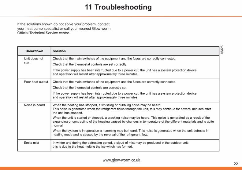
Breakdown Solution
Unit does notstart
Check that the main switches of the equipment and the fuses are correctly connected.
Poor heat output
Check that the thermostat controls are set correctly.
If the power supply has been interrupted due to a power cut, the unit has a system protection deviceand operation will restart after approximately three minutes.
Check that the main switches of the equipment and the fuses are correctly connected.
Check that the thermostat controls are correctly set.
If the power supply has been interrupted due to a power cut, the unit has a system protection deviceand operation will restart after approximately three minutes.
When the unit is started or stopped, a cracking noise may be heard. This noise is generated as a result of theexpanding or contracting of the housing caused by changes in temperature of the different materials and is quite normal.
Noise is heard When the heating has stopped, a whistling or bubbling noise may be heard.This noise is generated when the refrigerant flows through the unit, this may continue for several minutes after the unit has stopped.
Emits mist In winter and during the defrosting period, a cloud of mist may be produced in the outdoor unit;this is due to the heat melting the ice which has formed.
When the system is in operation a humming may be heard. This noise is generated when the unit defrosts in heating mode and is caused by the reversal of the refrigerant flow.
1532
5
If the solutions shown do not solve your problem, contact your heat pump specialist or call your nearest Glow-worm Official Technical Service centre.
11 Troubleshooting

www.glow-worm.co.uk23
www.high-efficiency.info
Because of our constant endeavour for improvement, details may vary slightly from those shown in these instructions.
Glow-worm, Nottingham Road, Belper, Derbyshire. DE56 1JT
0020084984-02 06.09