Embed Size (px)
Citation preview

Air Valves for Vertical Pump Applications
Table of Contents
Introduction . . . . . . . . . . . . . . . . . . . . . . . . . . . . . . . 2 Surges. . .. . . . . . . . . . . . . . . . . . . . . . . . . . . . . . . . . . 2 Entrapped Air. . . . . . . . . . . . . . . . . . . . . . . . . . . . . . 3 Vertical Pumps. . . . . . . . . . . . . . . . . . . . . . . . . . . . . 3 Air/Vacuum Valve Operation . . . . . . . . . . . . . . . . . 3 Regulated ‐Exhaust Devices. . . . . . . . . . . . . . . . . .. 5 Dual Port Throttling Devices . . . . . . . . . . . . . . . . .. 5 Application Criteria . . . . . . . . . . . . . . . . . . . . . . . . . 6 Sizing Pump Service Air Valves . . . . . . . . . . . . . . . . 7 Installation Guidelines . . . . . . . . . . . . . . . . . . . . . .. 8
VM‐AVVP/WP
Val‐Matic Valve & Mfg. Corp. • www.valmatic.com • [email protected] • PH: 630‐941‐7600 Copyright © 2018 Val‐Matic Valve & Mfg. Corp.
White Paper

Air Valves for Vertical Pump Applications
2
Introduction The purpose of this white paper is to provide guidance on specifying and installing Air/Vacuum Valves for vertical pumps. A vertical turbine or deep well pump (Figure 1), lifts water from a water reservoir or well into a pipeline. When the pump is off, the water level in the pump column is below the pump discharge pipe and the pump column refills with air after each pump stoppage. Air valves play an important roll in automatically venting air and controlling surges in pump columns. Air/Vacuum valves with optional devices are designed to slowly exhaust air on pump start‐up and rapidly admit air upon pump shut down. Smaller Air/Vacuum Valves are equipped with Dual Port Throttling Devices on ½ to 3 inch sizes (Figure 2) and Regulated‐Exhaust Devices on 4 inch and larger sizes (Figure 3). The Air/Vacuum Valve is normally‐open and float‐operated to automatically vent or admit air at high rates. When water enters the air valve, the float automatically rises and closes to prevent discharge of the water. The requirements for Air Valves are described in American Water Works Standard AWWA C512. AWWA Air/Vacuum Valves have a large orifice equal to the inlet size for discharging air in large volumes at low pressures, typically 2 psi.
FIGURE 1. Vertical Pump with Well Service Air Valve
To properly select Air/Vacuum Valves for pump discharge, some fundamentals of surge control and entrapped air must first be understood.
Surges Surges (or water hammer) result from sudden changes in flow velocity. The effects of surges can be devastating because the magnitude of surges are approximately 100ft(43 psi) for every 1 ft/sec change in flow velocity. And, the surge pressure is additive to the static pressure in the pipe.

Air Valves for Vertical Pump Applications
3
For example, if a flow of 8 ft/sec is suddenly stopped in a pipe, a surge pressure as high as 350 psi above the static pressure may be produced. Hence, pumping systems are carefully designed with consideration to the starting and stopping sequences of the pumps. Many pumps are furnished with variable frequency motor starters that ramp up and ramp down the speed of the pump so that the fluid velocity changes more slowly. Nevertheless, pumps starting with an air‐filled pump column provide rapid flow initially and the discharge of the air in the pump column should be regulated, yet fully vented before the check valve opens.
Entrapped Air For a pumping system to operate efficiently, any free air in the pipeline must be automatically removed. If air collects at the high points, a restriction occurs, which will cause headloss and potentially lead to surges when the pocket of air moves from one location to another. The combination of air and water will also accelerate corrosion of the pipe wall. Air pockets can also move along the pipeline and pass through partially open valves causing sudden changes in the water velocity and surges. For example, if air is rapidly discharged from a hydrant, the high velocity water will be suddenly slowed because water is 200 times more dense than the air and cannot pass as quickly through the hydrant. Finally, air that reaches the end of the main will disturb the water systems of the end user.
Vertical Pumps Vertical pumps have air‐filled discharge columns when not running. For example, a well pump is typically submerged several hundred feet and isolated from the pipeline by a check valve mounted at ground level. When the pump is off, the water level drops to the normal water level in the well and a large column of air collects in the pump column (Figure 1). Air is always present in the column of a vertical turbine pump installed over a wet well. If the vertical turbine pump is started without an air valve, the air in the pump column would be pressurized and forced through the check valve into the pipeline causing air related problems. All vertical pumps should have an air valve installed just upstream of the check valve.
Air/Vacuum Valve Operation Air/Vacuum Valves are mounted on the pump discharge pipe upstream of the check valve and are designed to vent the air before the check valve is pushed open by the pump pressure. When the pump stops, the air/vacuum valve will reopen and admit air into the pump column to prevent the formation of a vacuum as the water column drains. When the valve is closed, the float is held upward tight against the resilient seat. The seat is contained in a precision register in the valve cover and held in place with a baffle assembly, which also guides the float.

Air Valves for Vertical Pump Applications
4
FIGURE 2. 1”‐3” Air Valve
Pump service is a severe application for air valves because when the pump is started, it runs for the first few seconds against little or no head. Hence, the actual flow rate is often as high as 150% of the normal flow rate while the air is being vented. Also, because of the high dynamics involved, the air discharge can reach sonic velocities and water may bypass the rapidly closing air valve. Therefore, the valve outlet should be piped back to the wet well or an open drain. Not only is the flow high, but there is a moment of time when the last of the air is vented and the water reaches the air valve with virtually no place to go. The water column can crash into the closing air valve and the closed check valve disc. If the water velocity striking the closed check valve is high, high surges may occur in the pump column and discharge pipe. Therefore, Throttling Devices (Figure 4) are provided to control the rate of air release. Surges in the pump column can also be minimized by using soft‐start pump motor controls.
Air Valves for Vertical Pump Applications
5
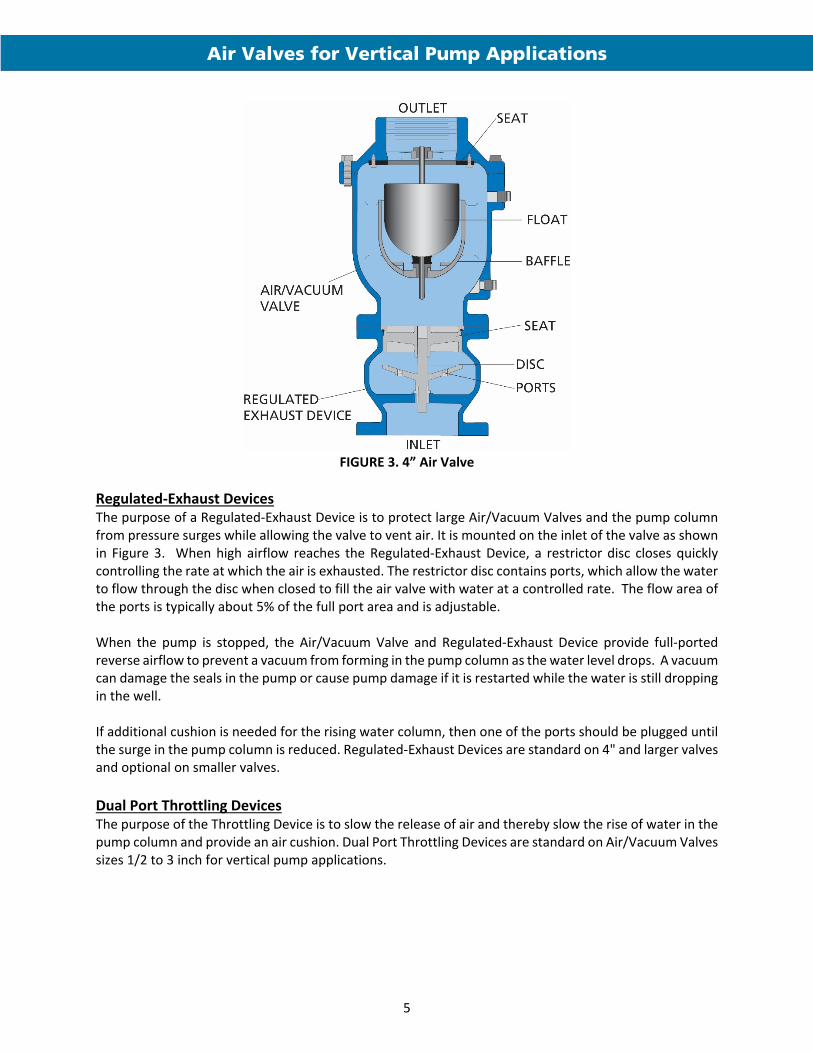
FIGURE 3. 4” Air Valve
Regulated‐Exhaust Devices The purpose of a Regulated‐Exhaust Device is to protect large Air/Vacuum Valves and the pump column from pressure surges while allowing the valve to vent air. It is mounted on the inlet of the valve as shown in Figure 3. When high airflow reaches the Regulated‐Exhaust Device, a restrictor disc closes quickly controlling the rate at which the air is exhausted. The restrictor disc contains ports, which allow the water to flow through the disc when closed to fill the air valve with water at a controlled rate. The flow area of the ports is typically about 5% of the full port area and is adjustable. When the pump is stopped, the Air/Vacuum Valve and Regulated‐Exhaust Device provide full‐ported reverse airflow to prevent a vacuum from forming in the pump column as the water level drops. A vacuum can damage the seals in the pump or cause pump damage if it is restarted while the water is still dropping in the well. If additional cushion is needed for the rising water column, then one of the ports should be plugged until the surge in the pump column is reduced. Regulated‐Exhaust Devices are standard on 4" and larger valves and optional on smaller valves.
Dual Port Throttling Devices The purpose of the Throttling Device is to slow the release of air and thereby slow the rise of water in the pump column and provide an air cushion. Dual Port Throttling Devices are standard on Air/Vacuum Valves sizes 1/2 to 3 inch for vertical pump applications.

Air Valves for Vertical Pump Applications
6
FIGURE 4. Dual‐Port Throttling Device A Throttling Device has an exhaust disc, which is typically adjusted between 5% and 30% open to control the venting rate. The valve needs to be set in the field and tuned to the operation of the pump. The Throttling Device should be opened just enough so that all of the air is discharged before the check valve opens. Opening the throttling device further will increase the pressure surge in the pump column. The Throttling Device also allows air to re‐enter the pump column when the pump is stopped to prevent a vacuum. A vacuum can damage the seals in the pump or cause pump damage if it is restarted while the water is still dropping in the well. To provide positive assurance against a vacuum, a Dual‐Port Throttling Device is needed where the vacuum port is separate from the exhaust port. If there is a common outlet, then the vacuum flow will be greatly restricted through the air discharge pipe. The discharge of vertical pump air valves are piped to drains and can be a source of cross connection. A Dual‐Port Throttling Device reduces any potential for contaminated water being drawn into the system by vacuum during pump shut down. The separate hooded port allows entry of atmospheric air instead of suction from the discharge pipe.

Air Valves for Vertical Pump Applications
7
Application Criteria The general operating parameters for the vertical pump air valves are summarized in the table below. A comprehensive presentation of features and dimensions is presented in Val‐Matic Air Valve Bulletin 1500.
Standard Operating Parameters Valve Series 100ST‐112FSS
Parameter Typical Range of Use
Size Range 1/2” – 12”
CWP Ratings 150 and 300 psig
Max Temp 250F
Orientation Vertical
Connection
½ to 3 in., NPT 4‐12 in., Flanged
Sizing Pump Service Air Valves Traditionally, valves used for vertical pump service applications were sized very conservatively at a differential pressure of 0.5 psi so that the water velocity entering the valve was not excessive. When using a Dual Port Throttling Device or Regulated‐Exhaust Device, a differential pressure of 2 psi is used as shown in the table below.
Air Valve Sizing For Pump Service
Size Pump GPM (at 0 head)
150 PSI Model No.
300 PSI Model No.
½"
0‐350
100ST
1"
351‐1350
101ST
2"
1351‐4000
102ST
3"
4001‐7000
103ST
4"
7001‐11,000
104SS
154SS
6"
11,001‐24,000
106SS
156SS
8"
24,001‐50,000
108SS
158SS
10"
50,001‐70,000
110FSS
160FSS
12"
70,001‐110,000
112FSS
162FSS
(T = Throttling Device, SS = Reg‐Exhaust Device)
Air Valves for Vertical Pump Applications
8
Installation Guidelines General recommendations for Pump Service Air Valves are based on the following parameters: 1. Type of Pump: All Vertical pumps require Air/Vacuum Valves or air will be forced into the pipeline
(Figure 1).
2. Type of Check Valve: Mechanical check valves such as Silent Check, Swing‐Flex® or Tilted‐Disc® Check
Valves require an Air/Vacuum Valve. Power actuated check valves such as a control valve or butterfly valve may use either an Air/Vacuum Valve or an Air Release Valve with delayed opening.
3. Sizing Pressure: Vertical Pump Service Air/Vacuum Valves are sized using the pump no‐load flow rate
and a differential pressure of 2 psi. 4. Piping: Vertical Pump Air Valves should be piped to the top of the discharge pipe with an isolation
valve. The pump discharge pipe should slope back to the well so that there is not water in the pipe when the pump starts or the air valve may close prematurely. The outlet of the air valve should be piped back to the wet well or to an open drain with an air gap.
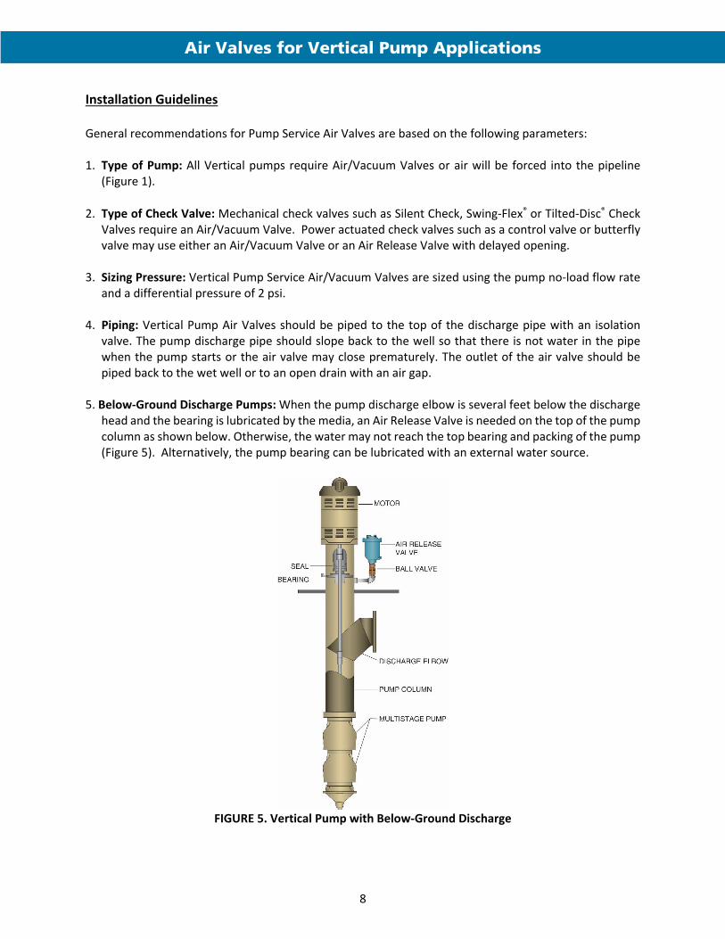
5. Below‐Ground Discharge Pumps: When the pump discharge elbow is several feet below the discharge
head and the bearing is lubricated by the media, an Air Release Valve is needed on the top of the pump column as shown below. Otherwise, the water may not reach the top bearing and packing of the pump (Figure 5). Alternatively, the pump bearing can be lubricated with an external water source.
FIGURE 5. Vertical Pump with Below‐Ground Discharge

Air Valves for Vertical Pump Applications
9
Disclaimer Val‐Matic White Papers are written to train and assist design engineers in the understanding of valves and fluid systems. Val‐Matic offers no warranty or representation as to design information and methodologies in these papers. Use of this material should be made under the direction of trained engineers exercising independent judgement.