Embed Size (px)
Citation preview
999 Robert-Bourassa Boulevard
Montréal, Quebec
Canada H3C 5H7
Tel.: +1 514 954-8219-
Fax: +1 514 954-6077-
Email: [email protected]
www.icao.int
International
Civil Aviation
Organization
Organisation
de l’aviation civile
internationale
Organización
de Aviación Civil
Internacional
Международная
организация
гражданской
авиации
Tel.: +1 (514) 954-8219 ext. 6718
Ref.: SP 65/4-15/22 13 May 2015
Subject: Proposal for the amendment of Annexes 4, 11,
15 and the PANS-OPS, Volumes I and II regarding
procedure design and oversight; harmonization
chart/database avionics requirements; existing work;
maintenance/ update of provisions; development of new
PBN design criteria; and provision of information for the
strategic development of PBN
Action required: Comments to reach Montréal by
13August 2015
Sir/Madam,
1. I have the honour to inform you that the Air Navigation Commission, at the eighth
meeting of its 198th Session on 10 March 2015, considered proposals developed by the twelfth meeting
of the Instrument Flight Procedures Panel (IFPP/12) to amend Annex 4 — Aeronautical Charts,
Annex 11 — Air Traffic Services, Annex 15 — Aeronautical Information Services and the Procedures for
Air Navigation Services — Aircraft Operations, Volume I — Flight Procedures and Volume II —
Construction of Visual and Instrument Flight Procedures (PANS-OPS, Doc 8168) regarding: procedure
design and oversight Standards and Recommended Practices (SARPs); harmonization chart/database
avionics requirements; existing work; work related to maintenance and update of provisions; development
of new performance-based navigation (PBN) design criteria to support current and future PBN operations;
and provision of information for the strategic development of PBN.
2. The amendment proposals address specific areas as listed and explained in Attachment A.
3. The proposed amendments to Annexes 4, 11, 15 and the PANS-OPS, Volumes I and II
are in Attachments B through F, respectively.
4. Attachment G presents, for your information, a draft Foreword and Table of Contents (in
English) for the Manual on the Development of a Regulatory Framework for Instrument Flight Procedure
Design Service (Doc xxxx) supporting the proposed Annex 11 amendment. This manual is being
developed to assist States with establishing a regulatory framework for instrument procedure design
service.

- 2 -
5. To facilitate your review of the proposed amendments, the rationale for each proposal has
been provided in the text boxes immediately following the proposals throughout Attachments B, C, D, E
and F.
6. In examining the proposed amendments, you should not feel obliged to comment on
editorial aspects as such matters will be addressed by the Air Navigation Commission during its final
review of the draft amendments.
7. May I request that any comments you may wish to make on the proposed amendments to
Annexes 4, 11, 15 and the PANS-OPS, Volumes I and II be dispatched to reach me not later than
13 August 2015. The Air Navigation Commission has asked me to specifically indicate that comments
received after the due date may not be considered by the Commission and the Council. In this connection,
should you anticipate a delay in the receipt of your reply, please let me know in advance of the due date.
8. In addition, the proposed amendments to Annexes 4, 11, 15 and the PANS-OPS,
Volumes I and II are envisaged for applicability on 10 November 2016. Any comments you may have
thereon would be appreciated.
9. The subsequent work of the Air Navigation Commission and the Council would be
greatly facilitated by specific statements on the acceptability or otherwise of the amendment proposal.
10. Please note that, for the review of your comments by the Air Navigation Commission and
the Council, replies are normally classified as “agreement with or without comments”, “disagreement
with or without comments”, or “no indication of position”. If in your reply the expressions “no
objections” or “no comments” are used, they will be taken to mean “agreement without comment” and
“no indication of position”, respectively. In order to facilitate proper classification of your response, a
form has been included in Attachment H which may be completed and returned together with your
comments, if any, on the proposals in Attachments B to F.
Accept, Sir/Madam, the assurances of my highest consideration.
Raymond Benjamin
Secretary General
Enclosures:
A — Background
B — Proposed amendment to Annex 4
C — Proposed amendment to Annex 11
D — Proposed amendment to Annex 15
E — Proposed amendment to PANS-OPS, Volume I
F — Proposed amendment to PANS-OPS, Volume II
G — Draft Foreword and Table of Contents for the Manual on the Development of Regulatory
Framework for Instrument Flight Procedure Design Service (Doc xxxx) (English only)
H — Response Form

ATTACHMENT A to State letter SP 65/4-15/22
BACKGROUND
The amendment proposals to Annexes 4, 11, 15 and PANS-OPS, Volumes I and II
address the following specific areas:
1. State responsibilities for instrument procedure design service: current ICAO provisions
are deficient with respect to State responsibilities for instrument design service. The Instrument Flight
Procedure Panel (IFPP), therefore, was tasked to develop the required Standard and Recommended
Practices (SARPs) to address this deficiency. Coordination was conducted with the Safety Management
Panel (SMP) to determine the requirement for a service to have a safety management system in place. The
SMP recommended that the extension of safety management system (SMS) requirements to instrument
procedure design should be considered at a later time. Consequently, the proposed amendment to
Annex 11 — Air Traffic Services provides the necessary SARPs for implementation today. The SMP and
the IFPP will continue to collaborate on the SMS requirement for instrument procedure design and
propose a future amendment to Annex 11, if necessary.
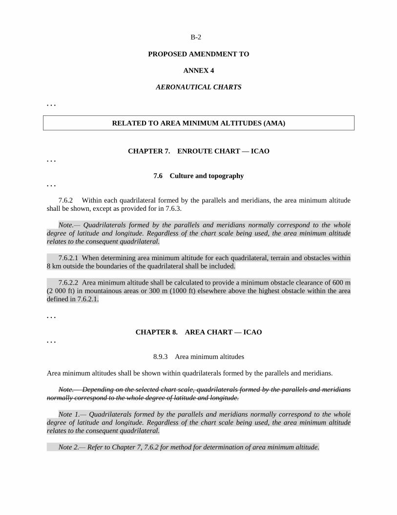
2. Harmonization chart/database/avionics requirements: area minimum altitude (AMA) is
defined in Annex 4 — Aeronautical Charts, but interpreting and determining an AMA is unclear. The
proposed amendment to Annex 4 provides clarification on establishing and publishing an AMA.
Conflicting information in ICAO provisions regarding en-route airway directional use restrictions has led
to confusion on how it is depicted in State aeronautical information publications (AIPs). The proposed
amendments to Annex 4, Annex 15 — Aeronautical Information Services and the Aeronautical
Information Services Manual (Doc 8126) resolves this issue and presents the necessary changes to
remove any confusion.
3. SBAS lines of minima: with the recent Amendment 6 to PANS-OPS, Volume II regarding
satellite-based augmentation system (SBAS) lines of minima, consequential amendments to Annex 4 and
the Aeronautical Chart Manual (Doc 8697) are now required.
4. Work related to maintenance/update of provisions: refinements to the criteria for
minimum obstacle clearance (MOC) for turning departures resulted in the proposed amendment to
PANS-OPS, Volumes I and II. This amendment supports application of independent parallel take-off
operations, facilitates application of 400 ft turn height for noise abatement and maximizes the flexibility
of PBN departure procedures.
5. Finally, additional proposed amendments to PANS-OPS, Volume II address both the
maximum length of a course to a fix (CF) on departure legs and Baro-vertical navigation (Baro-VNAV)
offset procedure criteria. The offset criteria allows design of instrument procedures with vertical guidance
at airports where a straight in Baro-VNAV approach cannot be designed, thus improving safety. The
amendment to CF provides additional clarity on the application for procedure designers.
6. Maintenance and update of provisions resulted in proposed amendments to Annex 4
regarding CAT H publication depiction requirements for all phases of helicopter flight and clarification of
fly-by and fly-over significant points depictions and functionality.
A-2
7. Use of PBN with ILS/MLS/GLS: new criteria that allow for the use of area navigation
(RNAV) or required navigation performance (RNP) with instrument landing system/microwave landing
system/GBAS landing system (ILS/MLS/GLS) resulted in proposed amendments to PANS-OPS,
Volume II. The amendments allow for transition from RNAV or RNP to ILS/MLS/GLS intermediate
segments and transition from ILS/MLS/GLS to RNAV or RNP missed approach, resulting in more
efficient terminal operations.
8. Amendment of SBAS and GBAS procedure design requirements: two main areas were
addressed under this issue – ground-based augmentation system (GBAS) information and approach with
vertical guidance II (APV II) criteria. The proposed amendment to PANS-OPS, Volume II includes the
removal of SBAS APV II criteria which are no longer required, changes to address inconsistencies
between Annex 10 — Aeronautical Telecommunications and PANS-OPS, Volume II regarding GBAS
final approach segment (FAS) data block, and the incorporation of GBAS system background information
that the procedure designer requires.
9. Visual segment surfaces: the safety requirement to have obstacle penetrations of the
visual segment surface (VSS) charted and the related proposed amendment to PANS-OPS, Volume II was
discussed in detail. Today, there is no requirement to chart penetrations of the VSS and, therefore, pilots
are unaware, creating a potential safety hazard.
— — — — — — — —

ATTACHMENT B to State letter SP 65/4-15/22
PROPOSED AMENDMENT TO ANNEX 4
NOTES ON THE PRESENTATION OF THE AMENDMENT
The text of the amendment is arranged to show deleted text with a line through it and new text highlighted
with grey shading, as shown below:
Text to be deleted is shown with a line through it. Text to be deleted
New text to be inserted is highlighted with grey shading. New text to be inserted
Text to be deleted is shown with a line through it
followed by the replacement text which is highlighted
with grey shading.
New text to replace existing text
B-2
PROPOSED AMENDMENT TO
ANNEX 4
AERONAUTICAL CHARTS
. . .
RELATED TO AREA MINIMUM ALTITUDES (AMA)
CHAPTER 7. ENROUTE CHART — ICAO
. . .
7.6 Culture and topography
. . .
7.6.2 Within each quadrilateral formed by the parallels and meridians, the area minimum altitude
shall be shown, except as provided for in 7.6.3.
Note.— Quadrilaterals formed by the parallels and meridians normally correspond to the whole
degree of latitude and longitude. Regardless of the chart scale being used, the area minimum altitude
relates to the consequent quadrilateral.
7.6.2.1 When determining area minimum altitude for each quadrilateral, terrain and obstacles within
8 km outside the boundaries of the quadrilateral shall be included.
7.6.2.2 Area minimum altitude shall be calculated to provide a minimum obstacle clearance of 600 m
(2 000 ft) in mountainous areas or 300 m (1000 ft) elsewhere above the highest obstacle within the area
defined in 7.6.2.1.
. . .
CHAPTER 8. AREA CHART — ICAO
. . .
8.9.3 Area minimum altitudes
Area minimum altitudes shall be shown within quadrilaterals formed by the parallels and meridians.
Note.— Depending on the selected chart scale, quadrilaterals formed by the parallels and meridians
normally correspond to the whole degree of latitude and longitude.
Note 1.— Quadrilaterals formed by the parallels and meridians normally correspond to the whole
degree of latitude and longitude. Regardless of the chart scale being used, the area minimum altitude
relates to the consequent quadrilateral.
Note 2.— Refer to Chapter 7, 7.6.2 for method for determination of area minimum altitude.

B-3
. . .
CHAPTER 9. STANDARD DEPARTURE CHART —
INSTRUMENT (SID) — ICAO
. . .
9.9.3 Minimum sector altitude
9.9.3.1 The established minimum sector altitude shall be shown with a clear indication of the sector
to which it applies.
9.9.3.2 Where the minimum sector altitude has not been established, the chart shall be drawn to scale
and area minimum altitudes shall be shown within quadrilaterals formed by the parallels and meridians.
Area minimum altitudes shall also be shown in those parts of the chart not covered by the minimum
sector altitude.
Note.— Depending on the selected chart scale, quadrilaterals formed by the parallels and meridians
normally correspond to the half-degree of latitude and longitude.
Note 1.— Quadrilaterals formed by the parallels and meridians normally correspond to the half
degree of latitude and longitude. Regardless of the chart scale being used, the area minimum altitude
relates to the consequent quadrilateral.
Note 2.— Refer to Chapter 7, 7.6.2 for method for determination of area minimum altitude.
. . .
CHAPTER 10. STANDARD ARRIVAL CHART —
INSTRUMENT (STAR) — ICAO
. . .
10.9.3 Minimum sector altitude
10.9.3.1 The established minimum sector altitude shall be shown with a clear indication of the
sector to which it applies.
10.9.3.2 Where the minimum sector altitude has not been established, the chart shall be drawn to
scale and area minimum altitudes shall be shown within quadrilaterals formed by the parallels and
meridians. Area minimum altitudes shall also be shown in those parts of the chart not covered by the
minimum sector altitude.
Note.— Depending on the selected chart scale, quadrilaterals formed by the parallels and meridians
normally correspond to the half-degree of latitude and longitude.
Note 1.— Quadrilaterals formed by the parallels and meridians normally correspond to the half
degree of latitude and longitude. Regardless of the chart scale being used, the area minimum altitude
relates to the consequent quadrilateral.
Note 2.— Refer to Chapter 7, 7.6.2 for method for determination of area minimum altitude.
B-4
. . .
Origin
IFPP/12
Rationale
Area Minimum Altitude is defined in Annex 4, Aeronautical Chart Manual
(Doc 8697) and PANS-OPS, Volume I. However, the implementation of AMA
by the States has been inconsistent, creating difficulty in interpretation by
operators and data providers. The notes in the proposed amendment address the
confusion and will lead to consistent implementation of AMAs.
RELATED TO EN-ROUTE AIRWAY DIRECTIONAL USE RESTRICTIONS
7.9 Aeronautical data
. . . 7.9.3 Air traffic services system
7.9.3.1 Where appropriate, the components of the established air traffic services system shall be
shown.
7.9.3.1.1 The components shall include the following:
. . .
d) All ATS routes for en-route flight including route designators, the track to the nearest degree in
both directions along each segment of the routes and, where established, the designation of the
navigation specification(s) including any limitations and the direction of traffic flow;
Note.— Guidance material on the organization of ATS routes for en-route flight publication which
may be used to facilitate charting is contained in the Aeronautical Information Services Manual
(Doc 8126).
. . .
Origin
IFPP/12
Rationale
There is conflicting information in ICAO provisions today regarding en-route
airway directional use restrictions. Annex 4, Annex 15 and the Aeronautical
Information Services Manual (Doc 8126) and the Aeronautical Chart Manual
(Doc 8697) all provide information on publishing en-route airways of all types.
The provisions in these documents is not sufficient or consistent to clearly
publish these kinds of restrictions. This leads to a significant amount of
interpretation by the data houses and there are examples where that
interpretation has not been compliant with the intent. This proposal addresses
inconsistency.
B-5
RELATED TO SBAS LINES OF MINIMA
CHAPTER 11. INSTRUMENT APPROACH CHART — ICAO
. . .
11.10 Aeronautical data
. . .
11.10.8 Supplementary information
. . .
11.10.8.8 If the final approach descent gradient/angle for any type of instrument approach
procedure exceeds the maximum value specified in the Procedures for Air Navigation Services —
Aircraft Operations (PANS-OPS, Doc 8168), Volume II, Part I, Section 4, Chapter 5, a cautionary note
shall be included.
. . .
Origin
IFPP/12
Rationale
The current reference is not appropriate as it does not include specific
requirements with regard to the specified maximum descent gradient/angle for
all the type of procedure being flown; hence the generalized text.
RELATED TO CAT H PUBLICATION REQUIREMENTS
FOR DEPARTURE AND ARRIVALS
CHAPTER 9. STANDARD DEPARTURE CHART —
INSTRUMENT (SID) — ICAO
. . .
9.9.4 Air traffic services system
9.9.4.1 The components of the established relevant air traffic services system shall be shown.
9.9.4.1.1 The components shall comprise the following:
a) a graphic portrayal of each standard departure route — instrument, including:

B-6
l) for departure procedures designed specifically for helicopters the term “CAT H” shall be
depicted in the departure chart plan view;
1) 2) route designator;
Editorial note.— Renumber subsequent paragraphs
accordingly.
. . .
CHAPTER 10. STANDARD ARRIVAL CHART —
INSTRUMENT (STAR) — ICAO
. . . 10.9.4 Air traffic services system
10.9.4.1 The components of the established relevant air traffic services system shall be shown.
10.9.4.1.1 The components shall comprise the following:
j) an indication of “flyover” significant waypoints. ;
k) for arrival procedures to an instrument approach designed specifically for helicopters the term
“CAT H” shall be depicted in the arrival chart plan view.
. . .
Origin
IFPP/12
Rationale
To clearly denote when an arrival and/or departure is specific to helicopter use
only.

B-7
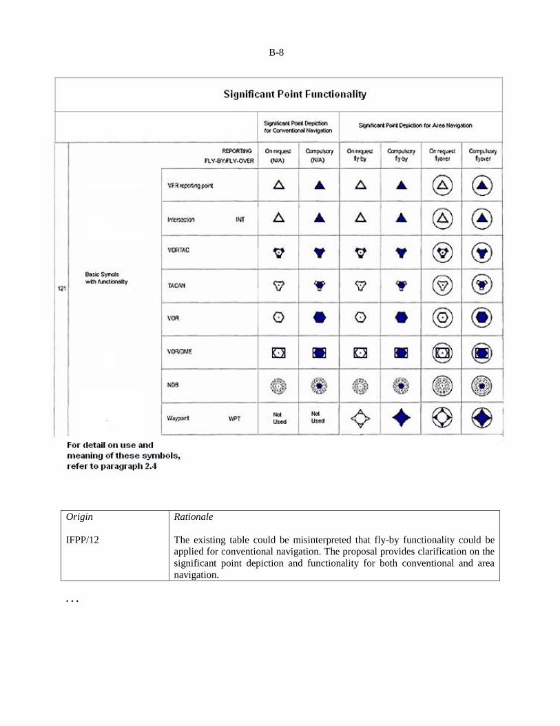
RELATED TO FLY-BY AND FLY-OVER FUNCTIONALITY FIXES
APPENDIX 2. ICAO CHART SYMBOLS
. . .
AIR TRAFFIC SERVICES
. . .
Editorial note.— Replace the section below by the new section
as follows:
B-8
Origin
IFPP/12
Rationale
The existing table could be misinterpreted that fly-by functionality could be
applied for conventional navigation. The proposal provides clarification on the
significant point depiction and functionality for both conventional and area
navigation.
. . .
B-9
RELATED TO VISUAL SEGMENT SURFACES (VSS)
CHAPTER 11. INSTRUMENT APPROACH CHART — ICAO
. . .
11.10 Aeronautical data
. . .
11.10.2 Obstacles
. . .
11.10.2.7 Where an obstacle free zone has not been established for a precision approach runway
Category I, this shall be indicated.
11.10.2.8 Obstacles that penetrate the visual segment surface shall be identified on the chart.
Note.— Guidance on the charting of VSS penetrations can be found in the Aeronautical Chart Manual
(Doc 8697).
. . .
Origin
IFPP/12
Rationale
PANS-OPS, Volume II allows for visual segment surface (VSS) penetration
under limited circumstances after an appropriate aeronautical study. This is a
consequential amendment.
— — — — — — — —

ATTACHMENT C to State letter SP 65/4-15/22
PROPOSED AMENDMENT TO ANNEX 11
NOTES ON THE PRESENTATION OF THE AMENDMENT
The text of the amendment is arranged to show deleted text with a line through it and new text highlighted
with grey shading, as shown below:
Text to be deleted is shown with a line through it. Text to be deleted
New text to be inserted is highlighted with grey shading. New text to be inserted
Text to be deleted is shown with a line through it
followed by the replacement text which is highlighted
with grey shading.
New text to replace existing text

C-2
TEXT OF PROPOSED AMENDMENT TO
ANNEX 11
AIR TRAFFIC SERVICES
. . .
RELATED TO STATE RESPONSIBILITIES FOR
INSTRUMENT PROCEDURE DESIGN SERVICE
CHAPTER 1. DEFINITIONS
. . .
Instrument flight procedure design service. A service established for the design, documentation,
validation, continuous maintenance and periodic review of instrument flight procedures necessary for
the safety, regularity and efficiency of air navigation.
. . .
CHAPTER 2. GENERAL
. . .
2.32 Instrument flight procedure design service
States shall ensure that an instrument flight procedure design service is in place in accordance with
Appendix 6.
. . .
Editorial note.— Insert new Appendix 6 as follows:
APPENDIX 6. STATE RESPONSIBILITIES CONCERNING
AN INSTRUMENT FLIGHT PROCEDURE DESIGN SERVICE (Note.— See Chapter 2, 2.32)
1. A State shall:
a) provide an instrument flight procedure design service; and/or
b) agree with one or more Contracting State(s) to provide a joint service; and/or
c) delegate the provision of the service to external agency(ies).
2. In all cases in paragraph 1 above, the State concerned shall approve and remain responsible
for all instrument flight procedures for aerodromes and airspace under the authority of the State.

C-3
3. Instrument flight procedures shall be designed in accordance with State-approved design
criteria.
4. Each State shall ensure that an instrument flight procedure design service provider intending
to design an instrument flight procedure for aerodromes or airspace under the responsibility of that State
meets the requirements established by that State’s regulatory framework.
Note.—Guidance material for regulatory framework for the oversight of instrument flight procedure
design service is contained in the Manual on the Development of a Regulatory Framework for Instrument
Flight Procedure Design Service (Doc XXXX).
5. A State shall ensure that an instrument flight procedure design service provider utilize a
quality management system at each stage of the instrument flight procedure design process.
Note.— This requirement can be met by means of a quality assurance methodology, such as that
described in PANS-OPS (Doc 8168), Volume II, Part I, Section 2, Chapter 4 — Quality Assurance.
Guidance for implementing such a methodology is contained in The Quality Assurance Manual for Flight
Procedure Design (Doc 9906).
6. A State shall ensure that continuous maintenance and periodic review of instrument flight
procedures for aerodromes and airspace under the responsibility of the State are conducted. Each State
shall establish an interval for periodic review of instrument flight procedures not exceeding five years.
Note.— Guidance on continuous maintenance and periodic review is contained in the Quality
Assurance Manual for Flight Procedure Design (Doc 9906).
End of new text
. . .
Origin
IFPP/12
Rationale
Responsibility by Contracting States on the provision of safe flight procedures
needs to be governed from SARPs, yet none exist in any Annex today. This
proposal addresses the deficiency and defines State responsibilities for
instrument procedure design service.
— — — — — — —

ATTACHMENT D to State letter SP 65/4-15/22
PROPOSED AMENDMENT TO ANNEX 15
NOTES ON THE PRESENTATION OF THE AMENDMENT
The text of the amendment is arranged to show deleted text with a line through it and new text highlighted
with grey shading, as shown below:
Text to be deleted is shown with a line through it. Text to be deleted
New text to be inserted is highlighted with grey shading. New text to be inserted
Text to be deleted is shown with a line through it
followed by the replacement text which is highlighted
with grey shading.
New text to replace existing text
D-2
TEXT OF PROPOSED AMENDMENT TO
ANNEX 15
AERONAUTICAL INFORMATION SERVICES
. . .
RELATED TO EN-ROUTE AIRWAY DIRECTIONAL USE RESTRICTIONS
APPENDIX 1. CONTENTS OF THE
AERONAUTICAL INFORMATION PUBLICATION (AIP)
(see Chapter 4)
. . .
PART 2 — EN-ROUTE (ENR)
. . .
ENR 3. ATS ROUTES
Note 1.— Bearings, tracks and radials are normally magnetic. In areas of high latitude, where it is
determined by the appropriate authority that reference to Magnetic North is impractical, another suitable
reference, i.e. True North or Grid North, may be used.
Note 2.— Changeover points established at the midpoint between two radio navigation aids, or at the
intersection of the two radials in the case of a route which changes direction between the navigation aids,
need not be shown for each route segment if a general statement regarding their existence is made.
Note 3.— Guidance material on the organization of ATS Route publication is contained in the
Aeronautical Information Services Manual (Doc 8126).
. . .
Origin
IFPP/12
Rationale
There is conflicting information in ICAO provisions today regarding en-route
airway directional use restrictions. Annexes 4, 15 and the Aeronautical
Information Services Manual (Doc 8126) and the Aeronautical Chart Manual
(Doc 8697) all provide information on publishing en-route airways of all types.
The provisions in these documents is not sufficient or consistent to clearly
publish these kinds of restrictions. This leads to a significant amount of
interpretation by the data houses and there are examples where that
interpretation has not been compliant with the intent. This proposal addresses
inconsistency.
— — — — — — — —

ATTACHMENT E to State letter SP 65/4-15/22
PROPOSED AMENDMENT TO PANS-OPS, VOLUME I
NOTES ON THE PRESENTATION OF THE AMENDMENT
The text of the amendment is arranged to show deleted text with a line through it and new text highlighted
with grey shading, as shown below:
Text to be deleted is shown with a line through it. Text to be deleted
New text to be inserted is highlighted with grey shading. New text to be inserted
Text to be deleted is shown with a line through it
followed by the replacement text which is highlighted
with grey shading.
New text to replace existing text
E-2
PROPOSED AMENDMENT TO
PROCEDURES FOR AIR NAVIGATION SERVICES —
AIRCRAFT OPERATIONS (DOC 8168)
VOLUME I
FLIGHT PROCEDURES
. . .
RELATED TO MINIMUM OBSTACLE CLEARANCE (MOC) REDUCTION DURING
TURNING DEPARTURES
PART I. FLIGHT PROCEDURES — GENERAL
. . .
SECTION 3. DEPARTURE PROCEDURES
. . .
Chapter 1
GENERAL CRITERIA FOR DEPARTURE PROCEDURES
. . .
1.4 OBSTACLE CLEARANCE
1.4.1 The minimum obstacle clearance equals zero at the departure end of the runway (DER). From
that point, it increases by 0.8 per cent of the horizontal distance in the direction of flight assuming a
maximum turn of 15°.
1.4.2 In the turn initiation area and turn area, a minimum obstacle clearance of 90 m (295 ft) 75 m
(246 ft) (Cat H, 65 m (213 ft)) is provided.
. . .
Chapter 3
OMNIDIRECTIONAL DEPARTURES
. . .
3.3 PROCEDURE DESIGN GRADIENT (PDG)
3.3.1 Unless otherwise specified, departure procedures assume a 3.3 per cent (helicopters, 5 per
cent) PDG and a straight climb on the extended runway centre line until reaching 120 m (394 ft)
(helicopters, 90 m (295 ft)) above the aerodrome elevation.
3.3.2 The basic procedure ensures:
a) the aircraft climbs on the extended runway centre line to 120 m (394 ft) (helicopters, 90 m
(295 ft)) before turns can be specified; and
E-3
b) at least 90 m (295 ft) 75 m (246 ft) (Cat H, 65 m (213 ft)) of obstacle clearance is provided before
turns greater than 15° are specified.
3.3.3 The omnidirectional departure procedure is designed using any one of a combination of the
following:
a) Standard case: Where no obstacles penetrate the 2.5 per cent obstacle identification surface
(OIS), and 90 m (295 ft) 75 m (246 ft) (Cat H, 65 m (213 ft)) of obstacle clearance prevails, a
3.3 per cent climb to 120 m (394 ft) (helicopters, 90 m (295 ft)) will satisfy the obstacle clearance
requirements for a turn in any direction (see Figure I-3-3-1 — Area 1).
. . .
Section 7
NOISE ABATEMENT PROCEDURES
. . .
Chapter 2
NOISE PREFERENTIAL RUNWAYS AND ROUTES
. . .
2.2.2 In establishing noise preferential routes:
a) turns during take-off and climb should not be required unless:
1) the aeroplane has reached (and can maintain throughout the turn) a height of not less than
150 m (500 ft) above terrain and the highest obstacles under the flight path;
Note.— PANS-OPS, Volume II, permits turns after take-off at 120 m (400 ft 394 ft)
(helicopters, 90 m (295 ft)) and obstacle clearance of at least 90 m (300 ft) 75 m (246 ft) (Cat H,
65 m (213 ft)) during the aeroplane’s turn. These are minimum requirements for noise abatement
purposes.
. . .
Origin
IFPP/12
Rationale
The changed MOC addresses misalignments and addresses better the
application of independent parallel take-off operations, maximizing the
flexibility through implementation of PBN departure procedures.
— — — — — — — —

ATTACHMENT F to State letter SP 65/4-15/22
PROPOSED AMENDMENT TO PANS-OPS, VOLUME II
NOTES ON THE PRESENTATION OF THE AMENDMENT
The text of the amendment is arranged to show deleted text with a line through it and new text highlighted
with grey shading, as shown below:
Text to be deleted is shown with a line through it. Text to be deleted
New text to be inserted is highlighted with grey shading. New text to be inserted
Text to be deleted is shown with a line through it
followed by the replacement text which is highlighted
with grey shading.
New text to replace existing text

F-2
PROPOSED AMENDMENT TO
PROCEDURES FOR AIR NAVIGATION SERVICES —
AIRCRAFT OPERATIONS (DOC 8168)
VOLUME II
CONSTRUCTION OF VISUAL AND INSTRUMENT FLIGHT PROCEDURES
. . .
RELATED TO MINIMUM OBSTACLE CLEARANCE (MOC) REDUCTION DURING
TURNING DEPARTURES
Part I
GENERAL
. . .
Section 3
DEPARTURE PROCEDURES
. . .
Chapter 2
GENERAL CONCEPTS FOR DEPARTURE PROCEDURES
. . .
2.2 DESIGN PRINCIPLES
. . .
2.2.9 Before any turn greater than 15° 15 degrees may be executed, a minimum obstacle clearance
of 90 m (295 ft) (Cat H, 80 m (265 ft)) 75 m (246 ft) (Cat H, 65 m (213 ft)) must be reached.
Alternatively, 0.8 per cent of the distance from the DER may be used, if this value is higher. This
minimum obstacle clearance must be maintained during subsequent flight.
. . .
2.5 MINIMUM OBSTACLE CLEARANCE (MOC)
. . .
2.5.3 In addition to the above prior to the commencement of a turn of more than 15 degrees, MOC
of 90 m (295 ft) (Cat H, 80 m (265 ft)) 75 m (246 ft) (Cat H, 65 m (213 ft)) is required.
. . .

F-3
Chapter 3
DEPARTURE ROUTES
. . .
3.3 TURNING DEPARTURES
3.3.1 General
. . .
3.3.1.3 The areas considered in the design of turning departures are defined as:
a) the turn initiation area; and
b) the turn area.
The turn initiation area is an area within which the aircraft conducts a straight climb in order to reach the
MOC required prior to the beginning of a turn (90 m (295 ft) (Cat H, 80 m (265 ft)) 75 m (246 ft) (Cat H,
65 m (213 ft)). The turn area is the area in which the aircraft is considered to be turning.
. . .
3.3.5 Turn at a specified altitude/height
. . .
3.3.5.3 Obstacle clearance calculation
a) Turn initiation area. The minimum obstacle clearance in the turn initiation area is calculated
using the horizontal distance from the DER measured along the nominal track, at the design PDG.
(See Chapter 2, 2.5, “Minimum obstacle clearance”.) Note that a turn may be commenced at the
specified turn altitude, and that normal aircraft performance will often result in this altitude being
reached before the end of the turn initiation area (TP). Therefore, the minimum obstacle clearance
for turning must also be provided above all obstacles in the turn initiation area. This criterion will
be met if the maximum obstacle elevation in the turn initiation area is:
1) maximum obstacle elevation/height = TNA/H – 90 m (295 ft) 75 m (246 ft) for aeroplanes;
and
2) maximum obstacle elevation/height = TNA/H – 80 m (265 ft) 65 m (213 ft) for helicopters.
b) Turn area. The minimum obstacle clearance in the turn area is calculated as follows.
1) Obstacles located before the TP (K-line). MOC is the greater of the minimum MOC for
turning (90 m (295 ft) (75 m (246 ft) (Cat H, 80 m/265 ft)) and 0.008 (dr* + do) where:
dr* is the distance measured along the departure track corresponding to the point on the turn
initiation area boundary where the distance do is measured, and
do is the shortest distance from the turn initiation area boundary to the obstacle.
F-4
2) Obstacles located after the TP (K-line). MOC is the greater of the minimum MOC for turning
(90 m (295 ft) (Cat H, 80 m/265 ft)) 75 m (246 ft) (Cat H, 65 m (213 ft)), and 0.008 (dr + do)
where:
. . .
3.3.6 Turn at a designated TP
. . .
3.3.6.4 Obstacle clearance in the turn area
. . .
where: do = shortest distance from obstacle to line K-K (see Figure I-3-3-11 c)
dr = horizontal distance from DER to line K-K (earliest TP)
PDG = promulgated procedure design gradient
H = OIS height at DER (5 m or 16 ft)
MOC = the greater of 0.008 (dr + do) and 90 m (295 ft) (Cat H, 80 m (265 ft)) 75 m (246 ft)
(Cat H, 65 m (213 ft))
. . .
Chapter 4
OMNIDIRECTIONAL DEPARTURES
. . .
4.3 OBSTACLE IDENTIFICATION
. . .
4.3.2 Identification of obstacles in the turn area
4.3.2.1 An obstacle in the turn area shall be considered if it penetrates a 2.5 per cent gradient (Cat H,
4.2 per cent) which starts at the boundary of the turn initiation area at a height of 90 m/295 ft (Cat H,
80 m/265 ft) 75 m (246 ft) (Cat H, 65 m (213 ft)) above the elevation of the DER. The gradient is
computed using the shortest distance from the boundary of the turn initiation area to the obstacle.
. . .
4.4 OBSTACLE CLEARANCE
. . .
4.4.2 Obstacle clearance in the turn area
a) The minimum obstacle clearance in the turn area is the greater of:
1) 90 m (295 ft) (Cat H, 80 m/265 ft) 75 m (246 ft) (Cat H, 65 m (213 ft)); and
F-5
. . .
Part III
PERFORMANCE-BASED NAVIGATION PROCEDURES
. . .
Section 3
PROCEDURE CONSTRUCTION
. . .
Chapter 1
DEPARTURE PROCEDURES
. . .
1.4 TURNING DEPARTURES
1.4.1 General
. . .
1.4.1.3 Modified straight departure criteria are applied to any Radius to Fix (RF) leg. The design
methodology for RF turns on departure is as follows:
. . .
f) If the MOC is less than or equal to 90m 75 m (246 ft), as defined in Part I, Section 3, Chapter 2,
the OIS is lowered to take account of body geometry (BG) from a point “ATT” prior to the start
of the RF leg. The OIS is kept level from that point until BG protection has been reached. The 0.8
per cent D + BG OIS is maintained during the RF turn until 90 m 75 m (246 ft) MOC is reached.
. . .
Origin
IFPP/12
Rationale
The changed MOC addresses misalignments and addresses better the
application of independent parallel take-off operations, maximizing the
flexibility through implementation of PBN departure procedures.
F-6
RELATED TO USE OF A COURSE TO A FIX (CF) ON DEPARTURE LEGS
Part III
PERFORMANCE-BASED NAVIGATION PROCEDURES
. . .
Section 2
GENERAL CRITERIA
. . .
Appendix to Chapter 5
PATH TERMINATOR CODING RULES
. . .
2. Table III-2-5-App-1 defines the path terminators that can support the initial and final legs of an
RNAV procedure (SID, STAR, approach and missed approach).
. . .
3. If a course to fix (CF) is used as the first leg of a sequence, the design shall be validated for
inadvertent low altitude banking of an aircraft.
. . .
Note 3.— As one of the methods to alleviate the possibility of inadvertent low altitude banking, the
use of a course to altitude (CA) leg type to an altitude of at least 400 ft above the DER elevation may be
considered before the course to fix (CF) leg type.
Note 4. — FM or VM may be used to terminate ‘Open STARs’ when radar vectoring is provided to
final approach. The choice of track (FM) or heading (VM) depends upon ATC requirements.
Note 4 5.— RF may only be used for RNP procedures flown by aircraft equipped with systems that
are compatible with ARINC 424-17, or later.
Editorial note.— Renumber subsequent
paragraphs accordingly.
. . .
Origin
IFPP/12
Rationale
The use of a CF leg type as the first leg type of a departure procedure can
result in unacceptable aircraft banking at low level. The proposed Note warns
the procedure designer and recommends a solution.

F-7
RELATED TO BAROMETRIC VERTICAL NAVIGATION (BARO-VNAV)
OFFSET PROCEDURES
Part III
PERFORMANCE-BASED NAVIGATION PROCEDURES
. . .
Section 3
PROCEDURE CONSTRUCTION
. . .
Chapter 4
APV/BAROMETRIC VERTICAL NAVIGATION
(BARO-VNAV)
. . .
4.3 APV SEGMENT
4.3.1 General
The APV segment for the Baro-VNAV approach contains the final descent segment for landing, and the
initial and intermediate segments of the missed approach. It shall should be aligned with the extended
runway centre line. Where it is physically impracticable to align the final approach segment with the
runway centre line, see paragraph 4.6. A turn at the FAF of up to 15° is allowed.
. . .
Editorial note.— Insert new paragraph 4.6 below and
renumber existing paragraph 4.6 to 4.7 accordingly.
4.6 BARO-VNAV APPROACH WITH
OFFSET FINAL APPROACH TRACK ALIGNMENT
4.6.1 Use of Baro-VNAV approach with offset alignment
4.6.1.1 In certain cases it may not be physically practicable to align the final approach segment
with the runway centreline because of obstacle problems. An offset final approach track shall not be
established as a noise abatement measure.
The final approach track shall intersect the runway extended centreline:
a) at an angle not exceeding 15 degrees; and
b) at a distance D before threshold providing at least a minimum stabilization distance (MSD) before
the point where the promulgated VPA reaches a height of 75 m (246 ft) above threshold elevation
(see Figure III-3-4-7).

F-8
4.6.1.2 The minimum stabilization distance (MSD) is the sum of L1 and L2, where:
L1 is the distance between the intercept point and the end of the turn
L2 is a 3 second delay to take into account the roll out distance
L1 = r × tan (θ/2)
L2 = 3 × V/3600
r = turn radius calculated with a 15° bank angle and the TAS (at aerodrome elevation) corresponding to
the final approach IAS + 19 km/h (10 kt)
θ = turn angle
In the above equations, if distances and turn radii are in NM, V is in kt; or
if distances and turn radii are in km, V is in km/h.
4.6.1.3 The general arrangement is shown in Figure III-3-4-7.
4.6.2 Obstacle clearance criteria
The provisions contained in 4.1 to 4.6 apply except that:
a) all the obstacle clearance surfaces and calculations are based on a fictitious runway aligned with
the final approach track. This fictitious runway has the same landing threshold elevation as the
real one;
b) the OCA/H for this procedure shall be at least equal to altitude/height of the promulgated VPA at
the intercept point plus MSD × tanVPA (see Figure III-3-4-7).
Figure III-3-4-7. Baro-VNAV with offset final approach track alignment
End of new text
. . .

F-9
Origin
IFPP/12
Rationale
Criteria does not currently exist for the design of a Baro-VNAV approach with
an offset final approach track alignment, resulting in approaches without
vertical guidance at some runways. This proposal addresses the deficiency and
leads to increased safety.
RELATED TO THE USE OF PBN WITH ILS/MLS/GLS
Part II
CONVENTIONAL PROCEDURES
. . .
Section 1
PRECISION APPROACHES
. . .
Chapter 1
INSTRUMENT LANDING SYSTEM (ILS)
. . .
Editorial note.— Amend Chapter 1 as follows and renumber references
to figures accordingly.
1.2 INITIAL APPROACH SEGMENT
1.2.1 General
The initial approach segment must ensure that the aircraft is positioned within the operational service
volume of the localizer on a heading that will facilitate localizer interception. For this reason, the general
criteria which apply to the initial segment (see Part I, Section 4, Chapter 3) are modified in accordance
with 1.2.2, “Initial approach segment alignment” and 1.2.3, “Initial approach segment area”. The initial
approach segment may be defined by an RNAV or RNP route, using RNAV or RNP systems for track
guidance. Only the systems capable of navigation accuracy of 1 NM or better in this phase of flight can be
considered. Refer to Part III, Section 1, Chapter 1, Table III-1-1-1 for the navigation specifications that
can be used for initial approach. The RNAV or RNP route shall terminate at an IF defined by RNAV or
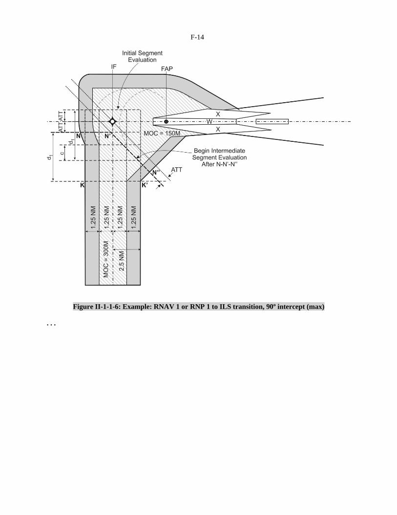
RNP located on the LOC course. RNAV/RNP turn construction is applicable for turns within the initial
segment and for the turn at the IF on the LOC course (see Figures II-1-1-5 and II-1-1-6). For RNAV or
RNP initial approach segments, the criteria in the applicable RNAV chapters Part III apply. If a course
reversal is required with an RNAV or RNP initial approach segment, only a racetrack can be used. The fix
and the inbound leg shall be located on the LOC course and the inbound segment defined by the LOC.

F-10
1.2.2 Initial approach segment alignment
The angle of interception between the initial approach track and the intermediate track should not exceed
90°. In order to permit the autopilot to couple on to the localizer, an interception angle not exceeding 30°
is desirable. When the angle exceeds 70° a radial, bearing, radar vector, or DME or RNAV information
providing at least 4 km (2 NM) (Cat H, 1.9 km (1 NM)) of lead shall be identified to assist the turn onto
the intermediate track. When the angle exceeds 90°, the use of a reversal, racetrack, or dead reckoning
(DR) track procedure should be considered (see Part I, Section 4, Chapter 3, “Initial Approach Segment”
and Part I, Section 4, Appendix A to Chapter 3, “Initial approach using dead reckoning (DR)”).
. . .
1.5 MISSED APPROACH SEGMENT
. . .
1.5.1.4 Missed approach segment using RNAV or RNP systems for track guidance can be
utilized. Only the systems capable of navigation accuracy of 1 NM or better in this phase of flight can be
considered. Refer to Part III, Section 1, Chapter 1, Table III-1-1-1 for the navigation specifications that
can be used for missed approach.
1.5.2 Straight missed approach
1.5.2.1 General. The precision segment terminates at the point where the Z surface reaches a
height 300 m above threshold. The width of the Z surface at that distance defines the initial width of the
final missed approach area which splays at an angle of 15 degrees from that point, as shown in
Figure II-1-1-15 II-1-1-17. There are no secondary areas.
1.5.2.2 Straight missed approach obstacle clearance. (See Figure II-1-1-16 II-1-1-18.) Obstacle
elevation/height in this final missed approach area shall be less than
. . .
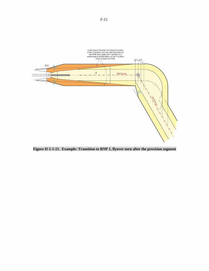
1.5.2.3 Transition to an RNAV or RNP missed approach may be designated with an RNAV or RNP
fix located on the extended LOC course, or with a turn at an altitude direct to a waypoint (see
Figure II-1-1-23). If the RNAV or RNP designated track is collinear with the LOC course, the area shall
be expanded at 15 degrees from abeam the SOC until it reaches the applicable width of the RNAV or
RNP area. In the region between the lateral boundaries of the Z surface and the outer boundaries of the
area, the obstacle evaluation shall be based on the Y surface and a mathematical extrapolation of the Y
surface where the area is outside the lateral boundaries of the OAS 300m contour. The Z surface shall
continue to splay at the same angle until reaching the width of the RNAV or RNP area. Secondary areas
shall apply from the point where the width of Z surface exceeds the width of RNAV or RNP primary area
(see Figure II-1-1-21). Obstacle clearance up to this point for the extended Y and Z surfaces shall be the
same as in the precision segment (see 1.4.8 “Obstacle clearance of the precision segment using obstacle
assessment surface (OAS) criteria”), and this shall also apply further out to all portions of the Z surface
that are within the RNAV or RNP primary area. The principle of secondary areas shall apply between
edge of the RNAV or RNP primary area and the edge of the total area. If an obstacle penetrates either the
extended Y or the Z surface within the secondary area, its elevation/height shall be less than:
(OCA/Hps – HL) + do tan Z + M
F-11
where:
a) OCA/H of the precision segment (OCA/Hps) and HL (Table II-1-1-2 value) both relate to the
same aircraft category.
b) do is measured from SOC parallel to the straight missed approach track;
c) Z is the angle of the missed approach surface with the horizontal plane; and
d) M is zero at the edge of the primary area increasing linearly to 30 m (98 ft) at the edge of the
total area.
1.5.3 Turning missed approach
1.5.3.1 General. Turns may be prescribed at a designated turning point (TP), at a designated
altitude/height, or “as soon as practicable”. The criteria used depend on the location of the turn relative to
the normal termination of the precision segment (see 1.4.6, “Termination”) and are as follows:
. . .
2) because SOC is related to OCA/H, it is not possible to obtain obstacle clearance by the means
used in non-precision approaches (that is, by independent adjustment of OCA/H or MAPt); and
b) turn before normal termination of the precision segment. If a turn is prescribed at a designated
altitude/height, which is less than 300 m above threshold, or at a designated TP such that the
earliest TP is within the normal termination range, the criteria specified in 1.5.3.2 and 1.5.3.3
below shall be applied. ;
c) for missed approaches using RNAV or RNP, fly-by or flyover turns should be limited to
90 degrees. RF turns are not permitted as the first RNP leg of the missed approach since there
would be no tangent RNP entry track specified. In this case a TF leg with the first waypoint
located on the extended LOC course is required preceding the RF leg;
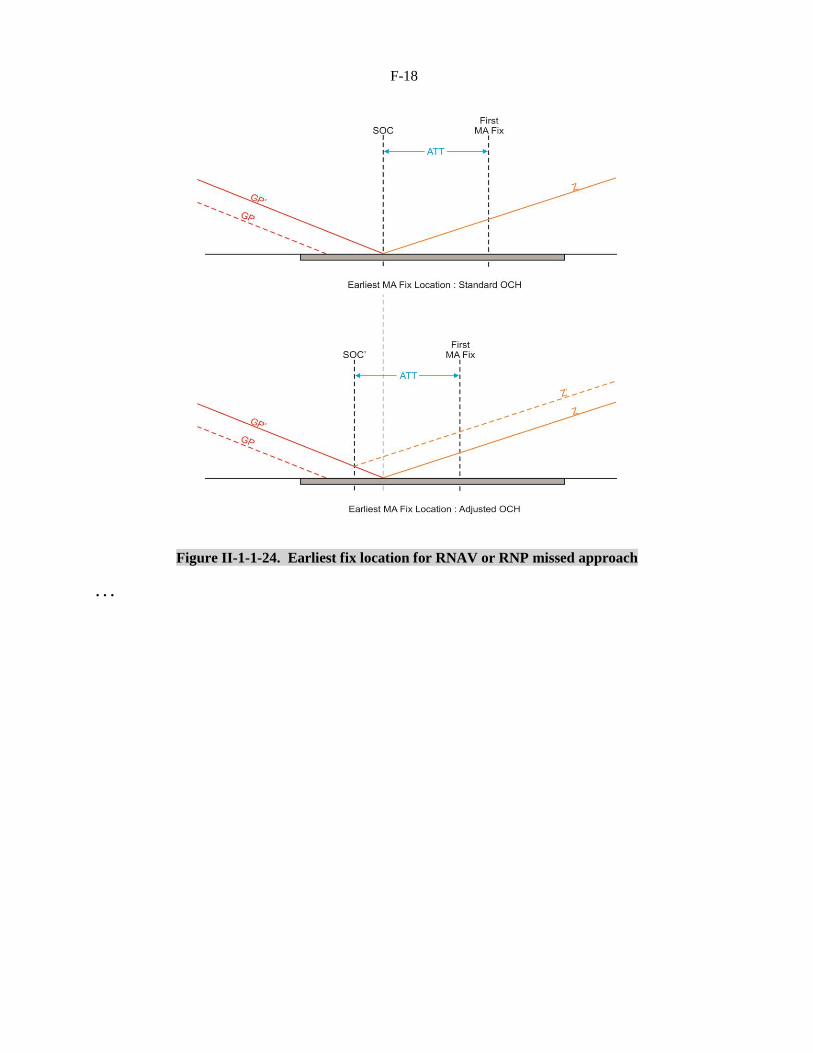
d) the earliest location of the first RNAV or RNP fix is at a distance of ATT after the SOC (see
Figure II-1-1-24). If the fix designates a fly-by turn, the additional distance d1+3 sec shall be
added prior to the fix (d1 = r tan A/2); and
e) for an RNAV or RNP missed approach, RNAV/RNP turn construction and turning MOC (50 m
(164 ft) for turns of more than 15º and 30 m (98 ft) for all other turns) shall apply after the earliest
turning point. Secondary areas shall apply between the standard width of the RNAV or RNP
primary area and the edge of the total area, except that obstacles located under the Y surface or its
extension on the outer side of the turn need not be considered. See Figures II-1-1-21 and II-1-1-22.
. . .
F-12
1.7 PROMULGATION
1.7.1 General
1.7.1.1 The general criteria in Part I, Section 2, Chapter 1, 1.9, “Promulgation” apply as amplified by
criteria in Part III, Section 5, Chapter 1, 1.3.4 for chart notes. The instrument approach chart for an ILS
approach procedure shall be identified by the title ILS Rwy XX. If Category II and/or III minima are
included on the chart, the title shall read ILS Rwy XX CAT II or ILS Rwy XX CAT II & III, as
appropriate. If more than one ILS approach is published for the same runway, the Duplicate Procedure
Title convention shall be applied, with the approach having the lowest minima being identified as ILS Z
RWY XX.
. . .

F-13
Editorial note.— Insert new Figures II-1-1-5 and II-1-1-6 as
follows and renumber existing figures and references
accordingly.
Figure II-1-1-5. Example: RNAV 1 or RNP 1 to ILS transition, 60° intercept
F-14
Figure II-1-1-6: Example: RNAV 1 or RNP 1 to ILS transition, 90º intercept (max)
. . .
F-15
Figure II-1-1-21. Example: Transition to RNP 1, flyover turn after the precision segment

F-16
Figure II-1-1-22. Example: Transition to RNAV 1 or RNP 1,
fly-by turn before the end of the precision segment

F-17
Figure II-1-1-23. Example: Turn at an altitude direct to an RNAV 1 or RNP 1 fix
F-18
Figure II-1-1-24. Earliest fix location for RNAV or RNP missed approach
. . .
F-19
Editorial note.— Amend Chapter 3 as follows and renumber references
to figures accordingly.
Chapter 3
MLS
. . .
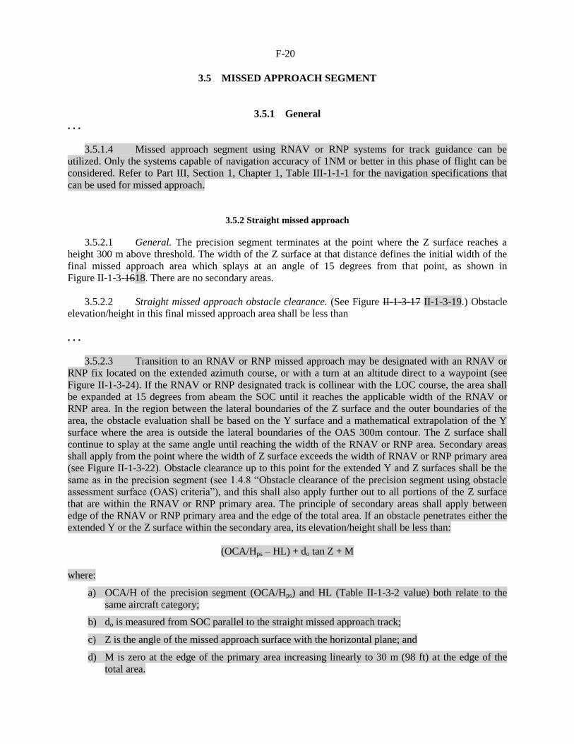
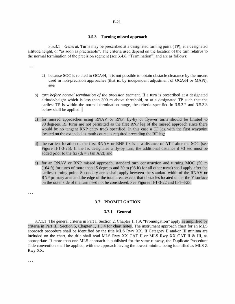
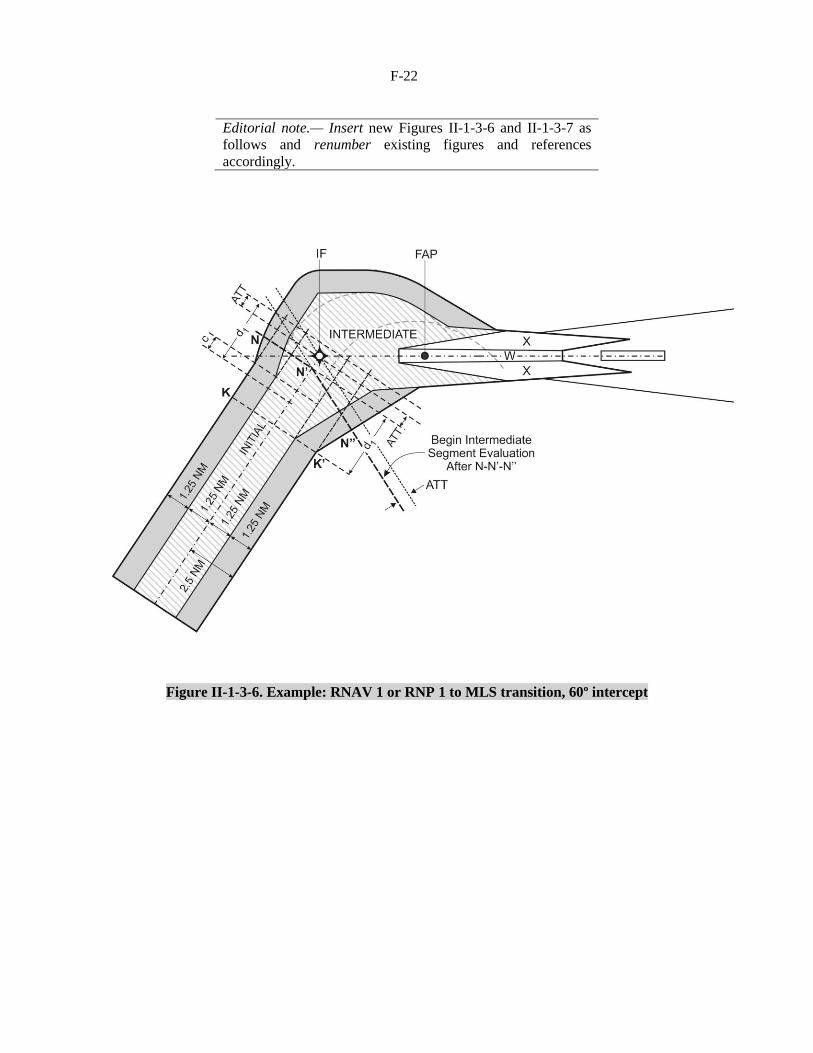
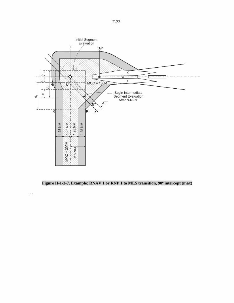
3.2 INITIAL APPROACH SEGMENT
3.2.1 General
The initial approach segment for MLS must ensure that the aircraft is positioned within the operational
service volume of the azimuth on a track that will facilitate azimuth interception. Consequently, the
general criteria applicable to the initial segment (see Part I, Section 4, Chapter 3) are modified in
accordance with 3.2.2, “Initial approach segment alignment” and 3.2.3, “Initial approach segment area”,
below. The initial approach segment may be defined by an RNAV or RNP route, using RNAV or RNP
systems for track guidance. Only the systems capable of navigation accuracy of 1 NM or better in this
phase of flight can be considered. Refer to Part III, Section 1, Chapter 1, Table III-1-1-1 for the
navigation specifications that can be used for initial approach. The RNAV or RNP route shall terminate at
an IF defined by RNAV or RNP located on the azimuth course. RNAV/RNP turn construction is
applicable for turns within the initial segment and for the turn at the IF on the azimuth course (see Figures
II-1-3-6 and II-1-3-7). For RNAV or RNP initial approach segments, the criteria in the applicable RNAV
chapters Part III apply. If a course reversal is required with an RNAV or RNP initial approach segment,
only a racetrack can be used. The fix and the inbound leg shall be located on the azimuth course and the
inbound segment defined by the azimuth.
3.2.2 Initial approach segment alignment
The angle of interception between the initial approach track and the intermediate track should not exceed
90°. In order to permit the autopilot to couple on to the azimuth, an interception angle not exceeding 30°
is desirable. When the angle exceeds 70°, a radial, bearing, radar vector, or DME or RNAV information
providing at least 4 km (2 NM) of lead shall be identified to assist the turn onto the intermediate track.
When the angle exceeds 90°, the use of a reversal, racetrack, or dead reckoning (DR) track procedure
should be considered (see Part I, Section 4, Chapter 3, “Initial approach segment” and Part I, Section 4,
Appendix A to Chapter 3, “Initial approach using dead reckoning (DR)”).
. . .
F-20
3.5 MISSED APPROACH SEGMENT
3.5.1 General
. . .
3.5.1.4 Missed approach segment using RNAV or RNP systems for track guidance can be
utilized. Only the systems capable of navigation accuracy of 1NM or better in this phase of flight can be
considered. Refer to Part III, Section 1, Chapter 1, Table III-1-1-1 for the navigation specifications that
can be used for missed approach.
3.5.2 Straight missed approach
3.5.2.1 General. The precision segment terminates at the point where the Z surface reaches a
height 300 m above threshold. The width of the Z surface at that distance defines the initial width of the
final missed approach area which splays at an angle of 15 degrees from that point, as shown in
Figure II-1-3-1618. There are no secondary areas.
3.5.2.2 Straight missed approach obstacle clearance. (See Figure II-1-3-17 II-1-3-19.) Obstacle
elevation/height in this final missed approach area shall be less than
. . .
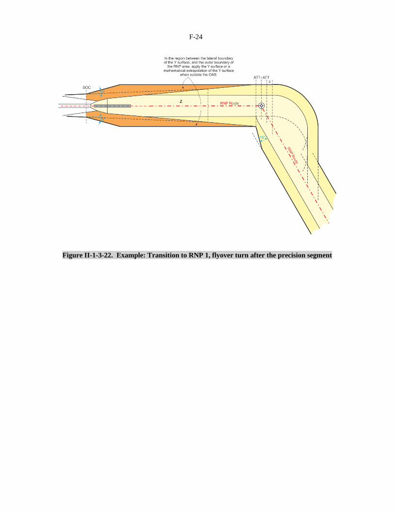
3.5.2.3 Transition to an RNAV or RNP missed approach may be designated with an RNAV or
RNP fix located on the extended azimuth course, or with a turn at an altitude direct to a waypoint (see
Figure II-1-3-24). If the RNAV or RNP designated track is collinear with the LOC course, the area shall
be expanded at 15 degrees from abeam the SOC until it reaches the applicable width of the RNAV or
RNP area. In the region between the lateral boundaries of the Z surface and the outer boundaries of the
area, the obstacle evaluation shall be based on the Y surface and a mathematical extrapolation of the Y
surface where the area is outside the lateral boundaries of the OAS 300m contour. The Z surface shall
continue to splay at the same angle until reaching the width of the RNAV or RNP area. Secondary areas
shall apply from the point where the width of Z surface exceeds the width of RNAV or RNP primary area
(see Figure II-1-3-22). Obstacle clearance up to this point for the extended Y and Z surfaces shall be the
same as in the precision segment (see 1.4.8 “Obstacle clearance of the precision segment using obstacle
assessment surface (OAS) criteria”), and this shall also apply further out to all portions of the Z surface
that are within the RNAV or RNP primary area. The principle of secondary areas shall apply between
edge of the RNAV or RNP primary area and the edge of the total area. If an obstacle penetrates either the
extended Y or the Z surface within the secondary area, its elevation/height shall be less than:
(OCA/Hps – HL) + do tan Z + M
where:
a) OCA/H of the precision segment (OCA/Hps) and HL (Table II-1-3-2 value) both relate to the
same aircraft category;
b) do is measured from SOC parallel to the straight missed approach track;
c) Z is the angle of the missed approach surface with the horizontal plane; and
d) M is zero at the edge of the primary area increasing linearly to 30 m (98 ft) at the edge of the
total area.
F-21
3.5.3 Turning missed approach
3.5.3.1 General. Turns may be prescribed at a designated turning point (TP), at a designated
altitude/height, or “as soon as practicable”. The criteria used depend on the location of the turn relative to
the normal termination of the precision segment (see 3.4.6, “Termination”) and are as follows:
. . .
2) because SOC is related to OCA/H, it is not possible to obtain obstacle clearance by the means
used in non-precision approaches (that is, by independent adjustment of OCA/H or MAPt);
and
b) turn before normal termination of the precision segment. If a turn is prescribed at a designated
altitude/height which is less than 300 m above threshold, or at a designated TP such that the
earliest TP is within the normal termination range, the criteria specified in 3.5.3.2 and 3.5.3.3
below shall be applied. ;
c) for missed approaches using RNAV or RNP, fly-by or flyover turns should be limited to
90 degrees. RF turns are not permitted as the first RNP leg of the missed approach since there
would be no tangent RNP entry track specified. In this case a TF leg with the first waypoint
located on the extended azimuth course is required preceding the RF leg;
d) the earliest location of the first RNAV or RNP fix is at a distance of ATT after the SOC (see
Figure II-1-3-25). If the fix designates a fly-by turn, the additional distance d1+3 sec must be
added prior to the fix (d1 = r tan A/2); and
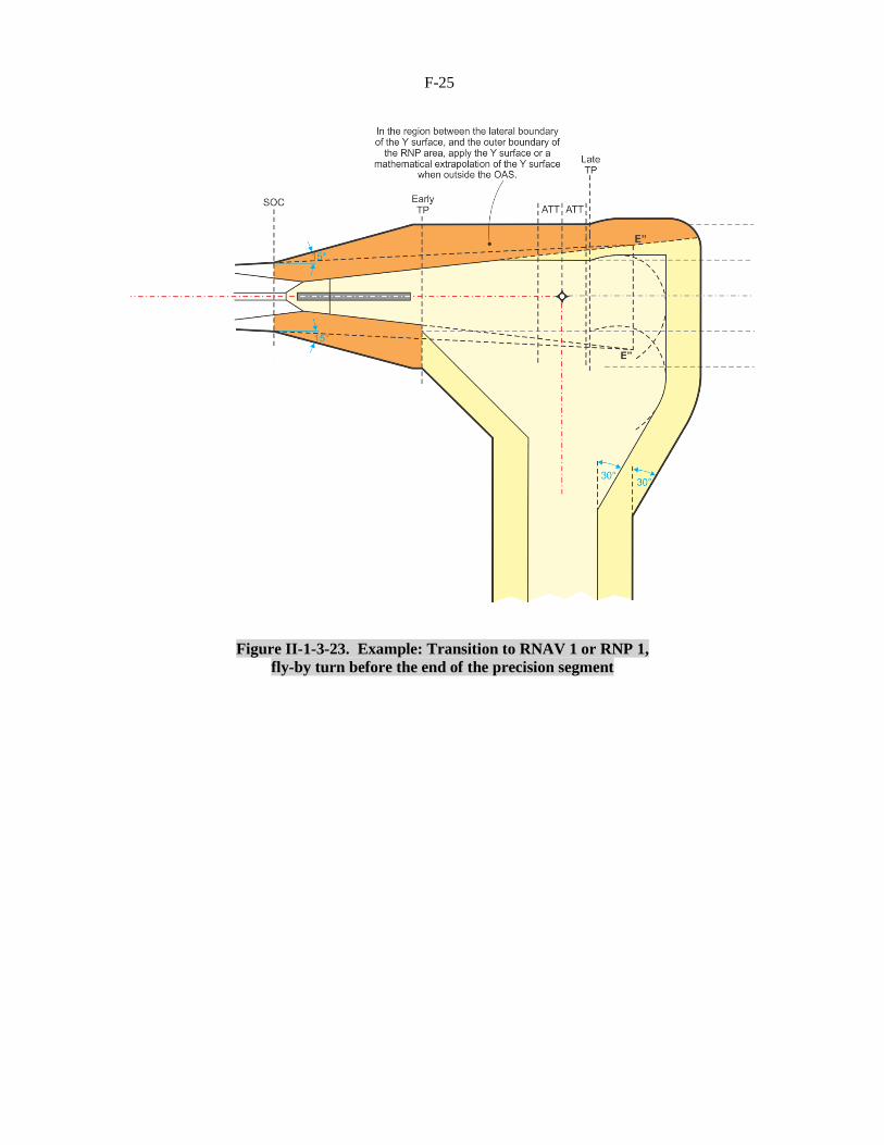
e) for an RNAV or RNP missed approach, standard turn construction and turning MOC (50 m
(164 ft) for turns of more than 15 degrees and 30 m (98 ft) for all other turns) shall apply after the
earliest turning point. Secondary areas shall apply between the standard width of the RNAV or
RNP primary area and the edge of the total area, except that obstacles located under the Y surface
on the outer side of the turn need not be considered. See Figures II-1-3-22 and II-1-3-23.
. . .
3.7 PROMULGATION
3.7.1 General
3.7.1.1 The general criteria in Part I, Section 2, Chapter 1, 1.9, “Promulgation” apply as amplified by
criteria in Part III, Section 5, Chapter 1, 1.3.4 for chart notes. The instrument approach chart for an MLS
approach procedure shall be identified by the title MLS Rwy XX. If Category II and/or III minima are
included on the chart, the title shall read MLS Rwy XX CAT II or MLS Rwy XX CAT II & III, as
appropriate. If more than one MLS approach is published for the same runway, the Duplicate Procedure
Title convention shall be applied, with the approach having the lowest minima being identified as MLS Z
Rwy XX.
. . .
F-22
Editorial note.— Insert new Figures II-1-3-6 and II-1-3-7 as
follows and renumber existing figures and references
accordingly.
Figure II-1-3-6. Example: RNAV 1 or RNP 1 to MLS transition, 60º intercept
F-23
Figure II-1-3-7. Example: RNAV 1 or RNP 1 to MLS transition, 90º intercept (max)
. . .
F-24
Figure II-1-3-22. Example: Transition to RNP 1, flyover turn after the precision segment
F-25
Figure II-1-3-23. Example: Transition to RNAV 1 or RNP 1,
fly-by turn before the end of the precision segment

F-26
Figure II-1-3-24. Example: Turn at an altitude
direct to an RNAV 1 or RNP 1 fix

F-27
Figure II-1-3-25. Earliest fix location for RNAV or RNP missed approach
. . .

F-28
Part III
PERFORMANCE-BASED NAVIGATION PROCEDURES
. . .
Section 3
PROCEDURE CONSTRUCTION
. . .
Chapter 5
SBAS NON-PRECISION APPROACH, APPROACH
WITH VERTICAL GUIDANCE AND PRECISION APPROACH
CATEGORY I PROCEDURES
. . .
5.7.1.3 The general arrangement is shown in Figure III-3-6-18 III-3-6-24.
. . .
Chapter 6
PRECISION APPROACH PROCEDURES — GBAS
. . .
6.2 INITIAL APPROACH SEGMENT
6.2.1 General
The initial approach segment for GBAS must ensure that the aircraft is positioned within the operational
service volume of the GBAS on a track or heading that will facilitate final approach course interception.
For this reason, the general criteria, which apply to the initial segment (see Chapter 2), are modified in
accordance with 6.2.2, “Alignment” and 6.2.3, “Area”. The initial approach segment may be defined by
an RNAV or RNP route, using RNAV or RNP systems for track guidance. Only the systems capable of
navigation accuracy of 1 NM or better in this phase of flight can be considered. Refer to Part III, Section
1, Chapter 1, Table III-1-1-1 for the navigation specifications that can be used for initial approach. The
RNAV or RNP route shall terminate at an IF defined by RNAV or RNP located on the final approach
course. RNAV/RNP turn construction is applicable for turns within the initial segment and for the turn at
the IF on the final approach course (see Figures III-3-6-4 and III-3-6-5). For RNAV or RNP initial
approach segments, the criteria in the applicable RNAV chapters Part III apply. If a course reversal is
required with an RNAV or RNP initial approach segment, only a racetrack can be used. The fix and the
inbound leg shall be located on the final approach course and the inbound segment defined by GBAS.
6.2.2 Initial approach segment alignment
The angle of interception between the initial approach track and the intermediate track should not exceed
90°. In order to permit the auto pilot to couple on to the final approach course, an interception angle not
exceeding 30° is desirable. When the angle exceeds 70° a radial, bearing, radar vector, DME or RNAV
information providing at least 4 km (2 NM) (Cat H, 1.9 km (1 NM)) of lead shall be identified to assist
F-29
the turn onto the intermediate track. When the angle exceeds 90°, the use of a reversal, racetrack, or dead
reckoning (DR) track procedure (see Part I, Section 4, Chapter 3, Appendix A, “Initial approach using
dead reckoning (DR)”) should be considered.
. . .
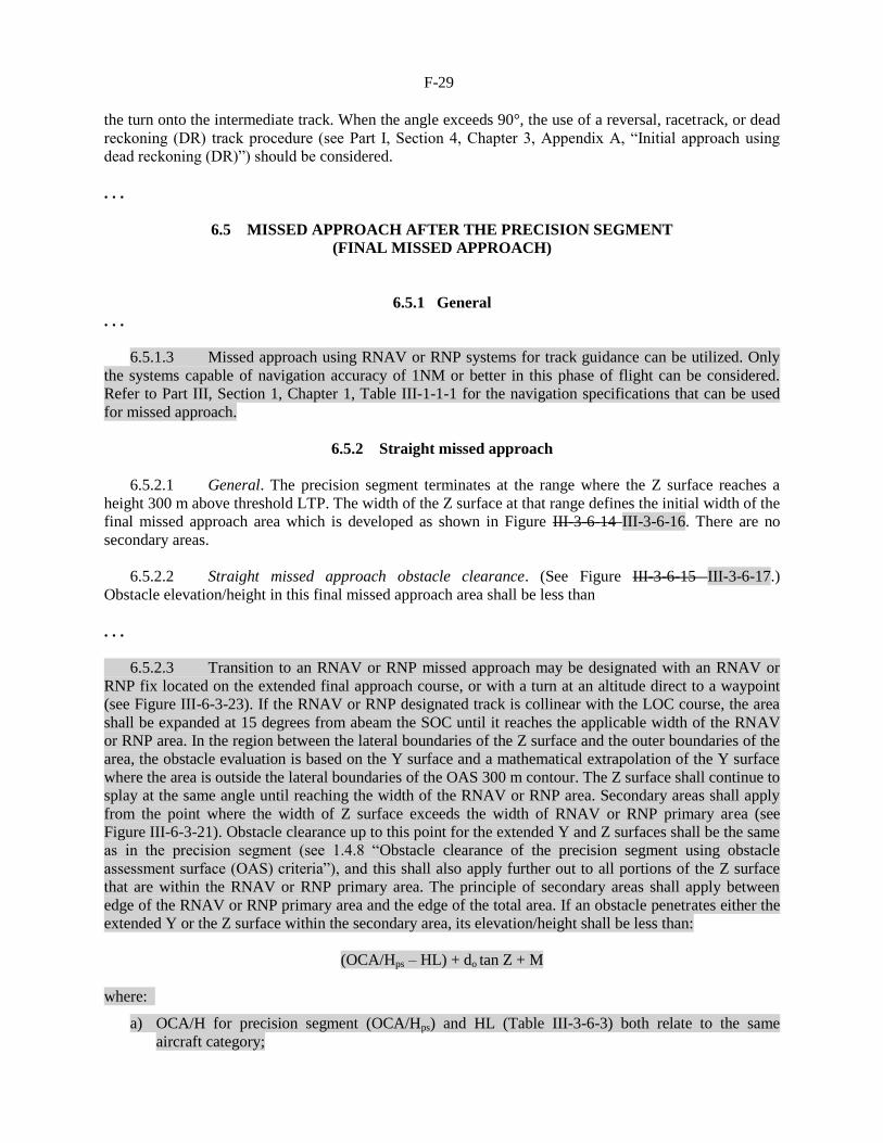
6.5 MISSED APPROACH AFTER THE PRECISION SEGMENT
(FINAL MISSED APPROACH)
6.5.1 General
. . .
6.5.1.3 Missed approach using RNAV or RNP systems for track guidance can be utilized. Only
the systems capable of navigation accuracy of 1NM or better in this phase of flight can be considered.
Refer to Part III, Section 1, Chapter 1, Table III-1-1-1 for the navigation specifications that can be used
for missed approach.
6.5.2 Straight missed approach
6.5.2.1 General. The precision segment terminates at the range where the Z surface reaches a
height 300 m above threshold LTP. The width of the Z surface at that range defines the initial width of the
final missed approach area which is developed as shown in Figure III-3-6-14 III-3-6-16. There are no
secondary areas.
6.5.2.2 Straight missed approach obstacle clearance. (See Figure III-3-6-15 III-3-6-17.)
Obstacle elevation/height in this final missed approach area shall be less than
. . .
6.5.2.3 Transition to an RNAV or RNP missed approach may be designated with an RNAV or
RNP fix located on the extended final approach course, or with a turn at an altitude direct to a waypoint
(see Figure III-6-3-23). If the RNAV or RNP designated track is collinear with the LOC course, the area
shall be expanded at 15 degrees from abeam the SOC until it reaches the applicable width of the RNAV
or RNP area. In the region between the lateral boundaries of the Z surface and the outer boundaries of the
area, the obstacle evaluation is based on the Y surface and a mathematical extrapolation of the Y surface
where the area is outside the lateral boundaries of the OAS 300 m contour. The Z surface shall continue to
splay at the same angle until reaching the width of the RNAV or RNP area. Secondary areas shall apply
from the point where the width of Z surface exceeds the width of RNAV or RNP primary area (see
Figure III-6-3-21). Obstacle clearance up to this point for the extended Y and Z surfaces shall be the same
as in the precision segment (see 1.4.8 “Obstacle clearance of the precision segment using obstacle
assessment surface (OAS) criteria”), and this shall also apply further out to all portions of the Z surface
that are within the RNAV or RNP primary area. The principle of secondary areas shall apply between
edge of the RNAV or RNP primary area and the edge of the total area. If an obstacle penetrates either the
extended Y or the Z surface within the secondary area, its elevation/height shall be less than:
(OCA/Hps – HL) + do tan Z + M
where:
a) OCA/H for precision segment (OCA/Hps) and HL (Table III-3-6-3) both relate to the same
aircraft category;

F-30
b) do is measured from SOC parallel to the straight missed approach track;
c) Z is the angle of the missed approach surface with the horizontal plane; and
d) M is zero at the edge of the primary area increasing linearly to 30 m (98 ft) at the edge of the total
area.
6.5.3 Turning missed approach
6.5.3.1 General. Turns may be prescribed at a designated TP, at a designated altitude/height, or “as
soon as practicable”. The criteria used depend on the location of the turn relative to the normal
termination of the precision segment and are as follows:
a) turn after normal termination of the precision segment. If a turn is prescribed after the normal
termination range of the precision segment, the criteria of Part I, Section 4, Chapter 6, 6.4.5,
“Turn initiated at a designated altitude/height” apply with the following exceptions:
. . .
2) Because SOC is related to OCA/H, it is not possible to obtain obstacle clearance by the
means used in non-precision approaches by independent adjustment of OCA/H or MAPt; and
b) turn before normal termination of the precision segment. If a turn is prescribed at a designated
altitude/height less than 300 m above threshold or at a designated TP such that the earliest TP is
within the normal termination range, the criteria specified in 6.5.3.2 and 6.5.3.3 below shall be
applied. ;
c) for missed approaches using RNAV or RNP, fly-by or flyover turns should be limited to 90
degrees. RF turns are not permitted as the first RNP leg of the missed approach since there would
be no tangent RNP entry track specified. In this case a TF leg with the first waypoint located on
the extended LOC course is required preceding the RF leg;
d) the earliest location of the first RNAV or RNP fix is at a distance of ATT after the SOC (see
Figure III-6-3-24). If the fix designates a fly-by turn, the additional distance d1+3 sec must be
added prior to the fix (d1 = r tan A/2); and
e) for an RNAV or RNP missed approach, standard turn construction and turning MOC (50 m
(164 ft) for turns of more than 15 degrees and 30 m (98 ft) for all other turns) shall apply after the
earliest turning point. Secondary areas shall apply between the standard width of the RNAV or
RNP primary area and the edge of the total area, except that obstacles located under the Y surface
on the outer side of the turn need not be considered. See Figures III-6-3-21 and III-6-3-22.
. . .
F-31
6.8 PROMULGATION
6.8.1 General
The general criteria in Part I, Section 4, Chapter 9, 9.5 apply as amplified by criteria in Part III, Section 5,
Chapter 1, 1.3.4 for chart notes. The instrument approach chart for a GBAS approach procedure shall be
identified by the title GLS Rwy XX. If more than one GBAS approach is published for the same runway,
the Duplicate Procedure Title convention shall be applied, with the approach having the lowest minima
being identified as GLS Z Rwy XX.
. . .
F-32
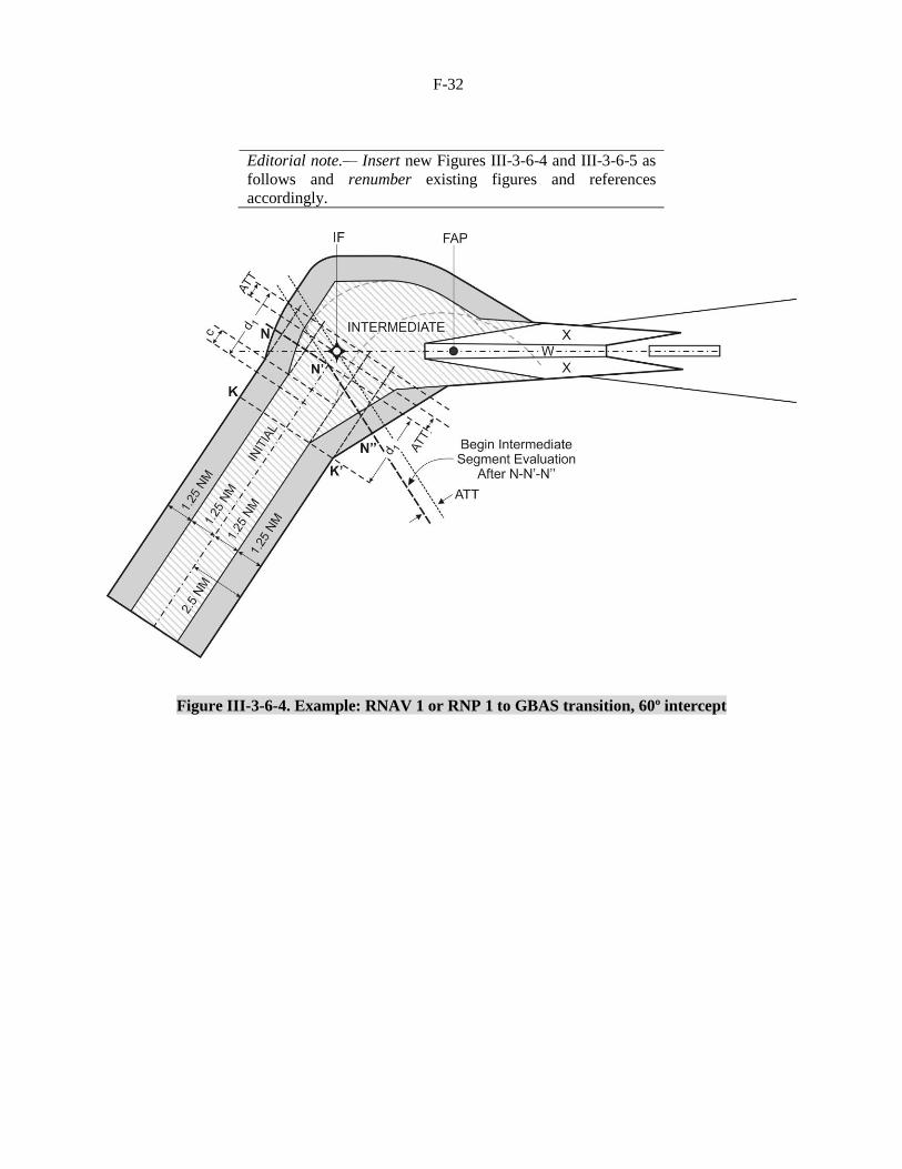
Editorial note.— Insert new Figures III-3-6-4 and III-3-6-5 as
follows and renumber existing figures and references
accordingly.
Figure III-3-6-4. Example: RNAV 1 or RNP 1 to GBAS transition, 60º intercept

F-33
Figure III-3-6-5. Example: RNAV 1 or RNP 1 to GBAS transition, 90º intercept (max)
. . .

F-34
Figure III-6-3-21. Example: Transition to RNP 1,
flyover turn after the precision segment
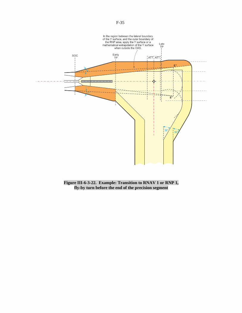
F-35
Figure III-6-3-22. Example: Transition to RNAV 1 or RNP 1,
fly-by turn before the end of the precision segment
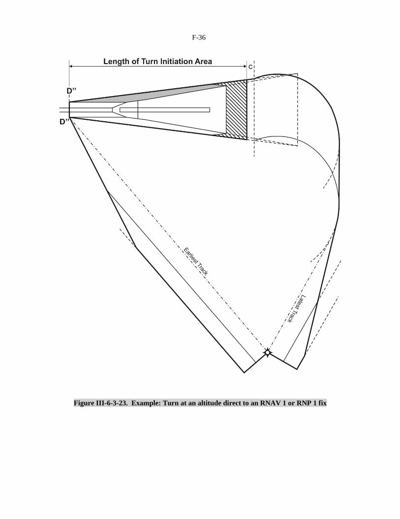
F-36
Figure III-6-3-23. Example: Turn at an altitude direct to an RNAV 1 or RNP 1 fix

F-37
Figure III-6-3-24. Earliest fix location for RNAV or RNP missed approach
. . .
Origin
IFPP/12
Rationale
Criteria does not currently exist for the RNAV and/or RNP transition to/from
ILS/MLS/GLS (intermediate and missed approach segments). This proposal
addresses this deficiency leading to improved efficiency in the terminal area.
F-38
RELATED TO GBAS FINAL APPROACH SEGMENT (FAS) DATA BLOCK
INCONSISTENCIES
Part III
PERFORMANCE-BASED NAVIGATION PROCEDURES
. . .
Section 2
GENERAL CRITERIA
. . .
Chapter 6.
APPLICATION OF FAS DATA BLOCK FOR SBAS AND GBAS
. . .
Appendix B to Chapter 6
ENCODING OF THE GBAS FAS DATA BLOCK
. . .
2. STRUCTURE AND CONTENT OF THE GBAS FAS DATA BLOCK
Note.— The definition and encoding of the GBAS FAS data block are found in Annex 10, Volume I,
Appendix B, Section 3.6.4.5 and Table B-66.
Editorial note.— Renumber subsequent paragraphs accordingly.
. . .
Origin
IFPP/12
Rationale
There are inconsistencies between Annex 10 and PANS-OPS, Volume II
regarding the GBAS final approach segment (FAS) data block creating
confusion for the procedure designer. This proposal removes the
inconsistencies.
F-39
RELATED TO THE REMOVAL OF APV II CRITERIA
Part III
PERFORMANCE-BASED NAVIGATION PROCEDURES
. . .
Section 3
PROCEDURE CONSTRUCTION
. . .
Chapter 5
SBAS NON-PRECISION APPROACH, APPROACH
WITH VERTICAL GUIDANCE AND PRECISION APPROACH
CATEGORY I PROCEDURES
5.1 INTRODUCTION
5.1.1 Procedure construction
This chapter describes the SBAS criteria for the NPA, APV APV I and PA Category I procedure segment,
which are specific to the performance of SBAS systems. Throughout this Chapter SBAS OAS refers to
both SBAS APV OAS and SBAS Category I OAS. The APV or Category I segment includes the final
approach, and the initial and the intermediate phases of the missed approach segment. The other phases of
flight are generic in character and are presented in Part III, Section 3, Chapter 1 and Chapter 2.
. . .
5.4 APV OR CATEGORY I SEGMENT
5.4.1 General. The APV APV I or Category I segment of an SBAS APV I, APV II or Category
I approach procedure shall be aligned with the runway centre line and contain the final approach, the
initial and the intermediate missed approach segments.
5.4.2 Origin. The APV APV I or Category I segment starts at the final approach point (the
intersection of the nominal vertical path and the minimum altitude specified for the preceding segment).
For navigation database coding purposes, the waypoint located at the FAP shall not be considered as a
descent fix. The SBAS OAS surfaces extend into the intermediate approach segment but not beyond this
segment (see Figure III-3-5-2).
. . .
5.4.4 Termination. The APV APV I or Category I segment terminates at the point where the
final phase of the missed approach commences or where the missed approach climb surface Z reaches a
semi-width of 1.76 km (0.95 NM) (for helicopters 1.48 km (0.8 NM)), whichever occurs first.
F-40
5.4.5 Obstacle clearance of the SBAS APV APV I or Category I segment
5.4.5.1 General. The method of calculating OCA/H involves a set of obstacle assessment
surfaces (SBAS APV OAS or SBAS Category I OAS). If the SBAS OAS are not penetrated, the OCA/H
is still defined by the aircraft category margins. However, if the SBAS OAS are penetrated, the aircraft
category margin is added to the highest approach obstacle, or the adjusted height of the largest missed
approach penetration, whichever is greater. This value becomes the OCA/H.
5.4.5.2 The SBAS OAS dimensions are related to the approach geometry (GARP/THR distance,
GP, RDH) and the category of SBAS operation procedure type (APV I, APV II or Category I). The
obstacles penetrating the SBAS OAS are divided into two classes, approach obstacles and missed
approach obstacles. The height of the highest approach obstacle or the adjusted missed approach surface
penetration (see 5.4.5.9.2) is determined and added to an aircraft category related margin to obtain the
appropriate OCA/H. Thus, a table of OCA/H values for each aircraft category may be promulgated for
SBAS operations at the particular aerodrome.
Note.— At this stage, the SBAS APV OAS method is the only one applicable to calculate the OCA/H
of the APV APV I segment. A CRM for these operations procedures is currently under development. Use
of the ILS Cat I CRM is permitted to calculate the SBAS Category I OCA/H.
5.4.5.3 Definition of surfaces. The SBAS APV OAS consists of up to seven sloping plane
surfaces (denoted by letters W, W’, X, Y, and Z) disposed symmetrically about the APV APV I or
Category I segment track and the horizontal plane containing the threshold (see Figure III-3-5-2). The
SBAS Category I OAS contains the following sloping surfaces: W, X, Y and Z, which are equal to the
ILS Category I OAS surfaces. The geometry of the sloping surfaces is precisely defined by four simple
linear equations of the form z = Ax + By + C. In these equations x and y are position coordinates and z is
the height of the surface at that position. For each surface the constants A, B and C are obtained from the
PANS-OPS OAS software (see http://www.icao.int/safety/AirNavigation/OPS/Pages/PANS-OPS-OAS-
Software.aspx) for the operational range of GARP/THR distances and GP. Separate sets of constants are
provided for APV I, APV II or Category I. The SBAS Category I OAS uses the ILS Cat I OAS constants.
The constants may be modified by the programme to account for the following:
. . .
5.4.5.6 Calculation of SBAS APV APV I OAS heights. To calculate the height z of any of the
sloping surfaces at a location x’, y’, the appropriate constants should be first obtained from the PANS-
OPS OAS software. These values are then substituted in the equation z = Ax’ + By’ + C. If it is not
apparent which SBAS APV APV I OAS is above the obstacle location, this should be repeated for the
other sloping surfaces. The SBAS APV OAS height is the highest of the X, Y, Z plane heights and the
height of the lowest W-W’ plane heights (zero if all the plane heights are negative). The SBAS Category I
OAS heights are calculated in the same way using the ILS Cat I OAS constants.
For APV I or APV II OAS, W and W’ planes intersect, and the accountable W-W’ plane is always the
lower of these two planes, i.e. height of OAS = max [ZX; ZY; ZZ; min ZW; ZW’]
Where ZX, ZY, ZZ, ZW and ZW’ are the heights of the X, Y, Z, W and W’ planes.
Note.— The PANS-OPS software also contains an OCH calculator that will show the height of the
SBAS APV or Category I OAS surface Z above any X, Y location. It includes all the adjustments specified
for the APV APV I or Category I approach geometry, aircraft dimensions, missed approach climb
gradient and RDH.

F-41
5.4.5.7 SBAS OAS template construction. Templates, or plan views of the SBAS OAS contours
to map scale, are sometimes used to assist identification of obstacles for detail survey (see Figure III-3-5-
5). The SBAS OAS data in the PANS-OPS software includes the coordinates of the points of intersection
of the sloping surfaces at threshold level and at 1.9 km (1.0 NM) laterally from the final approach track
(see Figure III-3-5-5). The intersection coordinates at threshold level are labelled as C, D and E.
. . .
5.4.5.9 Determination of OCA/H
5.4.5.9.1 General. The OCA/H is determined by accounting for all obstacles which penetrate the
SBAS OAS surfaces applicable to the SBAS category operation type being considered. The surfaces
which apply to each SBAS category of operations operation type are:
APV I operationType A, 3D operation: SBAS APV I OAS.
APV II operation: SBAS APV II OAS.
SBAS Category I operation Type B, 3D operation: ILS Category I OAS.
5.4.5.9.2 Determination of approach and missed approach obstacles. The accountable obstacles,
as determined in 5.4.5.9.1, are divided into approach and missed approach obstacles. The simplest method
of partition is by range: approach obstacles are those between the FAP and range XE after threshold, and
missed approach obstacles are those in the remainder of the APV APV I segment (see Figure III-3-5-6).
However, in some cases it may produce an excessive penalty for certain missed approach obstacles.
Where desired by the appropriate authority, missed approach obstacles may therefore be defined as those
above a plane surface parallel to the plane of the GP and with origin at – XE (see Figure III-3-5-7), i.e.
obstacle height greater than [(XE + x) tan θ].
5.4.5.9.3 Calculation of OCA/H. After the approach and missed approach obstacles have been
identified by one of the above described methods, the OCA/H is determined as follows:
a) determine the height of the highest approach obstacle;
b) reduce the heights of all missed approach obstacles to the heights of equivalent approach
obstacles by the formula given below; and
c) determine OCA/H by adding the appropriate Table II-1-1-2, “Height loss altimeter margin”
aircraft category related margin to the height of the highest approach obstacle (real or equivalent).
ha = hma ∗ cot Z + (X − XE)
[cot Z + cot θ]
where: ha = height of equivalent approach obstacle
hma = height of missed approach obstacle
θ = VPA
Z = angle of missed approach surface
X = range of obstacle relative to threshold (negative after threshold)
XE = 900 + (38/tan θ) for APV I and XE = 900 + (8/tan θ) for APV II
For Cat H, XE = 700 + (38/tan θ) for APV I and XE = 700 + (8/tan θ) for APV II.
F-42
hma, X and XE are expressed in metres (m).
. . .
5.4.5.9.4.2 Steep glide path angle. Procedures involving glide paths greater than 3.5° or any angle
when the nominal rate of descent (Vat for the aircraft type multiplied by the sine of the glide path angle)
exceeds 5 m/s (1 000 ft/min) are non-standard for fixed-wing aircraft. They require the following:
. . .
c) adjustment of the slope of the SBAS APV APV I OAS W and W’ surfaces or for SBAS
Category I OAS adjustment of the W surface;
. . .
5.5 MISSED APPROACH SEGMENT
5.5.1 General
5.5.1.1 The criteria for the final missed approach are based on those for the general criteria (see
Part I, Section 4, Chapter 6) with certain modifications to allow for the different areas and surfaces
associated with the APV APV I or Category I segment and the possible variation in OCA/H for that
segment with aircraft category.
. . .
5.5.1.3 Where obstacles identified in the final missed approach segment result in an increase in
any of the OCA/H calculated for the APV APV I or Category I segment, a higher gradient of the missed
approach surface (Z) may be specified in addition if this will provide clearance over those obstacles at a
specified lower OCA/H (see Part I, Section 4, Chapter 6, 6.2.2.2).
5.5.2 Straight missed approach
5.5.2.1 Termination of the APV APV I or Category I segment. The APV APV I or Category I
segment terminates at the range where the Z surface reaches a semi-width of 1.76 km (0.95 NM) (for
helicopters 1.48 km (0.8 NM)). For the straight part of the final missed approach the area semi-width is
equal to 1.76 km (0.95 NM) (for helicopters 1.48 km (0.8 NM)). Secondary areas are not applied. (See
Figure III-3-5-8).
. . .
5.5.3 Turning missed approach
5.5.3.1 General. For SBAS APV APV I procedures, the missed approach turn shall be prescribed
at a designated TP. Turns at a designated altitude/height or “as soon as practicable” cannot be
implemented because of the current SBAS receiver capabilities. The criteria used depend on the location
of the turn relative to the threshold and the normal termination of the APV or Category I segment and are
as follows:

F-43
a) turn outside APV APV I or Category I segment. If a turn is prescribed after the normal
termination range of the APV APV I or Category I segment, the general criteria of Part I, Section
4, Chapter 6, 6.4.6.4 apply with the following exceptions:
. . .
b) turn inside APV APV I or Category I segment. If a turn is prescribed at a designated TP such that
the earliest TP is within the normal termination range, the criteria specified in 5.5.3.2 and 5.5.3.3
below shall be applied.
5.5.3.2 Turn at a designated TP after the threshold with earliest TP before normal termination of
APV APV I or Category I segment. Where a turn is specified at a designated TP after the threshold, and
the earliest TP is before the normal termination range of the APV APV I or Category I segment, the APV
APV I or Category I segment is curtailed and terminates at the earliest TP. This allows the calculation of
OCA/HAPV and (OCA/HAPV – HL); SOC is then determined.
. . .
5.5.3.3.1 Turning point. A latest turning point is chosen to allow the aircraft to avoid obstacles
straight ahead. Then the turning point (TP) is plotted before the latest TP at a distance equivalent to 0.6
km (0.3 NM) plus 6 seconds of flight (pilot reaction and bank establishing time) at the final missed
approach speed (or maximum published missed approach speed) plus 56 km/h (30 kt) tailwind. For this
kind of turn the SOC is coincident with the earliest TP and the APV APV I or Category I segment
terminates at this point. The OCA/HAPV is equal to the altitude/height of the SOC increased by the HL
value.
5.5.3.3.2 Areas. The turn area is constructed as specified in Part I, Section 4, Chapter 6, except that
it is based on the width of the SBAS OAS Y surface contours at the earliest and latest TP (see Figure III-
3-5-11).
. . .
5.6 SIMULTANEOUS ILS/MLS/GBAS/APV SBAS
APPROACHES TO PARALLEL OR NEAR-PARALLEL
INSTRUMENT RUNWAYS
. . .
5.6.1 General
When it is intended to use an APV APV I or Cat I SBAS approach procedure to parallel runways,
simultaneously with ILS, MLS, GBAS or another APV APV I or Cat I SBAS approach procedure, the
following additional criteria shall be applied in the design of both procedures:
. . .
5.6.2 Obstacle clearance
The obstacle clearance criteria for APV APV I and Category I SBAS and precision approaches, as
specified in the designated chapters, apply for each of the parallel approach procedures. In addition to
these criteria, a check of obstacles shall be made in the area on the side opposite the other parallel
runway, in order to safeguard early turns required to avoid potential intruding aircraft from the adjacent
F-44
runway. This check can be made using a set of separately defined parallel approach obstacle assessment
surfaces (PAOAS). An example of a method to assess obstacles for these procedures is included in Part II,
Section 1, Chapter 1, Appendix D.
. . .
5.9 PROMULGATION
. . .
5.9.3 Minima box. A table of OCA/H values for each aircraft category may be promulgated for
SBAS operations at the particular aerodrome. All APV APV I and Cat I SBAS OCA/H’s OCA/Hs are
promulgated as LPV lines of minima. All non-precision approach SBAS OCA/Hs shall be promulgated as
LP (localizer performance) lines of minima. LPV and LP lines of minima shall not be published on the
same chart.
. . .
Origin
IFPP/12
Rationale
This proposal clarifies that only APV-I is relevant for SBAS.
F-45
RELATED TO GBAS SYSTEM BACKGROUND INFORMATION
Part III
PERFORMANCE-BASED NAVIGATION PROCEDURES
. . .
Section 3
PROCEDURE CONSTRUCTION
. . .
Editorial note.— Amend Chapter 6 as follows and renumber references
to figures accordingly.
Chapter 6
PRECISION APPROACH PROCEDURES — GBAS
6.1 INTRODUCTION
6.1.1 Application
The GBAS criteria in this chapter are based on ILS criteria and are related to the ground and airborne
equipment performance and integrity required to meet the Category I operational objectives described in
Annex 10. An illustration of the specific definitions used in this chapter is given in Figure III-3-6-1.
Note 1.— While specific GBAS Category I criteria are in preparation, the criteria contained in this
chapter are based on an ILS Category I equivalency method. Development of Annex 10 requirements for
Category II and III approaches is in progress; pending their finalization, procedure design criteria will
be made available.
Note 2.— GBAS is the ground-based GNSS augmentation system. The ground facility includes GBAS
reference receivers, a processor which prepares messages for broadcast and a VHF data broadcast
(VDB) system. The VDB is automatically tuned with the selection of the channel number in the range of
20 000 to 39 999.
Note 3.— The sensor minimum operational performance standards are found in RTCA DO-253C or
equivalent documents.
Note 4.— For each runway end supported by the system, the minimum Category I service volume is
described in Annex 10, Volume I, Chapter 3.7.3.5.3 and Attachment D, Chapter 7, paragraph 7.3 and
Figure D-4.
. . .
F-46
Origin
IFPP/12
Rationale
The additional notes provide GBAS background information that is considered
necessary for the procedure designer.
RELATED TO VISUAL SEGMENT SURFACES (VSS)
Part I
GENERAL
. . .
Section 4
ARRIVAL AND APPROACH PROCEDURES
. . .
Chapter 5
FINAL APPROACH SEGMENT
. . .
5.4 OBSTACLE CLEARANCE ALTITUDE/HEIGHT (OCA/H)
. . .
5.4.6 Protection for the visual segment of the approach procedure
. . .
5.4.6.4 If the VSS is penetrated, the approach procedure should shall not be promulgated without
an aeronautical study. Mitigation action as a result of such a study may result in the removal or lowering
of the obstacle, an increase of the descent gradient/angle and/or runway threshold displacement. Obstacles
with a height less than 15 m above the threshold may be disregarded when assessing the VSS. Temporary
moving obstacles such as aircraft holding at the runway hold-point are allowed.
5.4.6.5 Any penetration of the VSS shall be identified on the instrument approach chart.
. . .
Origin
IFPP/12
Rationale
There is no requirement to depict VSS penetration allowed by an aeronautical
study. This is considered a safety issue. The proposal makes it compulsory that
the penetration be depicted.
— — — — — — — —

ATTACHMENT G to State letter SP 65/4-15/22
DRAFT FOREWORD AND TABLE OF CONTENTS FOR THE
MANUAL ON THE DEVELOPMENT OF REGULATORY FRAMEWORK FOR
INSTRUMENT FLIGHT PROCEDURE DESIGN SERVICE (DOC XXXX)
FOREWORD
The instrument flight procedure (IFP) is an essential component of the aviation system. Every day and
during every flight, thousands of aircraft around the world are flying instrument departure, arrival or
approach procedures to airports in every country. It is a responsibility of ICAO Contracting States to
provide an instrument flight procedure design service (IFPDS) so operators are able to fly safe and
effective IFPs.
However, many States are still struggling with the implementation of an IFPDS. Contributing to this is
the lack of a standardized ICAO regulatory framework for the service, as well as guidance material to
support this. As a result, in some States, instrument flight procedures are developed and published
without appropriate regulatory involvement by the State and, in some cases, may even be completely
unregulated.
To address this, ICAO recognized the necessity to establish Standards and Recommended Practices
(SARPs) in Annex 11 — Air Traffic Services regarding the State responsibility for an IFPDS. In order to
support the SARPs, guidance material is developed describing how a regulatory framework for the
provision of an IFPDS may be implemented. This guidance material aims to enhance compliance to the
IFPDS SARPs found in Annex 11.
Chapter 2 of this document provides guidance material for States on developing a regulatory framework
for the provision of an IFPDS. The responsibilities of States (as per Annex 11) are reviewed (Section 2.1)
followed by a description of the components which comprise the regulatory framework to be established
by States (Section 2.2).
Chapter 3 of this document provides guidance material for the service provider(s) on developing their
work procedures (Section 3.2 and 3.3). In addition, other issues concerning procurement (Section 3.4),
quality assurance (Section 3.5), training and qualification of personnel (Section 3.6) and safety
management system (SMS) (Section 3.7) are addressed.
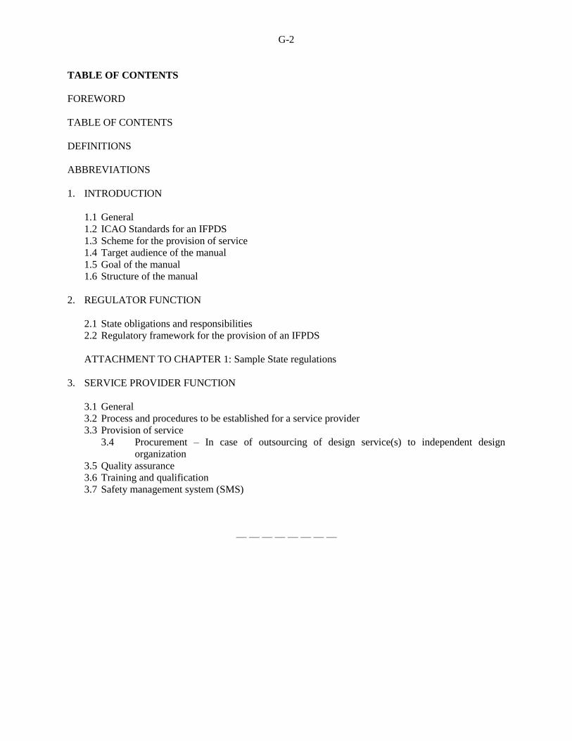
G-2
TABLE OF CONTENTS
FOREWORD
TABLE OF CONTENTS
DEFINITIONS
ABBREVIATIONS
1. INTRODUCTION
1.1 General
1.2 ICAO Standards for an IFPDS
1.3 Scheme for the provision of service
1.4 Target audience of the manual
1.5 Goal of the manual
1.6 Structure of the manual
2. REGULATOR FUNCTION
2.1 State obligations and responsibilities
2.2 Regulatory framework for the provision of an IFPDS
ATTACHMENT TO CHAPTER 1: Sample State regulations
3. SERVICE PROVIDER FUNCTION
3.1 General
3.2 Process and procedures to be established for a service provider
3.3 Provision of service
3.4 Procurement – In case of outsourcing of design service(s) to independent design
organization
3.5 Quality assurance
3.6 Training and qualification
3.7 Safety management system (SMS)
— — — — — — — —

ATTACHMENT H to State letter SP 65/4-15/22
RESPONSE FORM TO BE COMPLETED AND RETURNED TO ICAO TOGETHER
WITH ANY COMMENTS YOU MAY HAVE ON THE PROPOSED AMENDMENTS
To: The Secretary General
International Civil Aviation Organization
999 Robert-Bourassa Boulevard
Montréal, Quebec
Canada, H3C 5H7
(State)
Please make a checkmark () against one option for each amendment. If you choose options “agreement
with comments” or “disagreement with comments”, please provide your comments on separate sheets.
Agreement
without
comments
Agreement
with
comments*
Disagreement
without
comments
Disagreement
with
comments
No position
Amendment to Annex 4 — Aeronautical Charts
(Attachment B refers)
Amendment to Annex 11 — Air Traffic Services
(Attachment C refers)
Amendment to Annex 15 — Aeronautical
Information Services (Attachment D refers)
Amendment to Doc 8168, Procedures for Air
Navigation Services — Aircraft Operations,
Volume I — Flight Procedures (Attachment E
refers)
Amendment to Doc 8168, Procedures for Air
Navigation Services — Aircraft Operations,
Volume II — Construction of Visual and
Instrument Flight Procedures (Attachment F refers)
*“Agreement with comments” indicates that your State or organization agrees with the intent and overall
thrust of the amendment proposal; the comments themselves may include, as necessary, your reservations
concerning certain parts of the proposal and/or offer an alternative proposal in this regard.
Signature: Date:
— END —