Embed Size (px)
Citation preview
CODE:MK3045/MK3058
metran
AIR TO WATER ALL IN ONE HEAT PUMP
Installation & Instruction Manual
AIR TO WATER ALL IN ONE HEAT PUMP
1
metran
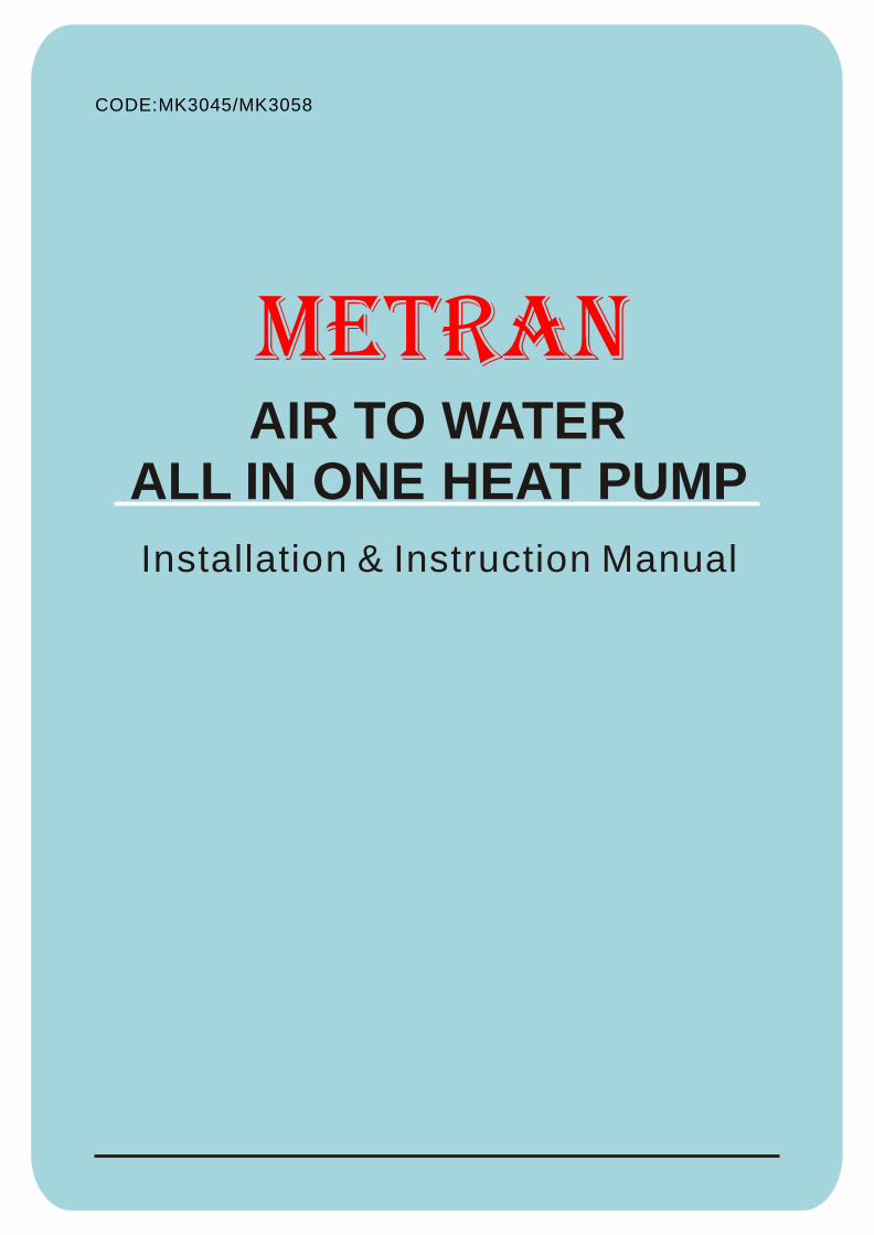
Contents
1. ONE OF THE WORLD'S MOST ENERGY EFFICIENT METHODS OF WATER
HEATING PRODUCTION.................................................................................. 3
2. FEATURES OF YOUR metran HEAT PUMP WATER HEATER............................. 3
2.1 With dynamic cycle flow heating system................................................... 3
2.2 High efficient and energy saving................................................................ 3
2.3 Safe, reliable and long operating life ,good durability................................. 4
2.4 Simple installation and convenience to use................................................ 4
2.5 Wide application to save your money......................................................... . 4
2.6 Model Nomenclature ................................................................................. 4
3. SPECIFICATIONS & DIMENSIONS.................................................................... 5
3.1 Technical parameters for the main unit................................................. 5
3.2 Main unit appearance and mounting dimension..................................... 6
4. INSTALLATION DETAILS................................................................................. . 6
4.1 General Installation Requirements............................................................. 6
4.2 Air Flow...................................................................................................... 6
4.3 Evaporator Drain........................................................................................ 6
4.4 Pressure & Temperature Relief Valve (PTR)................................................ 7
4.5 Expansion Control Valve (ECV).................................................................. 7
4.6 Cold Water Connection.............................................................................. 7
4.7 Pressure Reducing Valve........................................................................... 8
4.8 Suitability For Installation In Frost Areas................................................... 8
4.9 Draining Of Tank................................. ....................................................... 8
4.10 Hot Water Connection.............................................................................. 8
4.11 Tempering Valves..................................................................... ................ 8
4.12 Electrical Connection.............................................................................. 8
4.13 Caution Regarding Drilling Metal Jacket.................................................. 9
5. OPERATING INSTRUCTIONS........................................................................... 9
5.1 Filling The Water Heater............................................................................. 9
5.2 Air Expelling Of The Circulating Water Pump.......................... .................... 9
5.3 Water Quality............................................................................................. 9
5.4 Caution When Left Operating But Unused.................................................. 9
6: SAFETY INFORMATION.................................................................................. .10
6.1 Safety Devices.......................................................................................... .10
6.2 Important Note Regarding PTR Valve........................................................ . 10
AIR TO WATER ALL IN ONE HEAT PUMP
2
metran
Contents
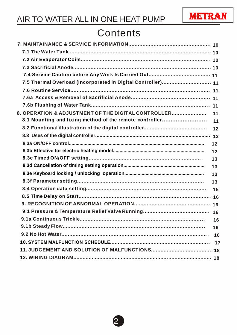
7. MAINTAINANCE & SERVICE INFORMATION................................................... . 10
7.1 The Water Tank.......................................................................................... 10
7.2 Air Evaporator Coils................................................................................. . 10
7.3 Sacrificial Anode....................................................................................... 10
7.4 Service Caution before Any Work Is Carried Out...................................... . 11
7.5 Thermal Overload (Incorporated in Digital Controller).............................. . 11
7.6 Routine Service.................................................................................. ...... 11
7.6a Access & Removal of Sacrificial Anode................................................. . 11
7.6b Flushing of Water Tank.......................................................................... . 11
8. OPERATION & ADJUSTMENT OF THE DIGITAL CONTROLLER...................... 11
8.1 Mounting and fixing method of the remote controller......................... . 11
8.2 Functional illustration of the digital controller....................................... . 12
8.3 Uses of the digital controller................................................................................ 12
8.3a ON/OFF control...................................................................................................... 12
8.3b Effective for electric heating model..................................................................... 12
8.3c Timed ON/OFF setting....................................................................... . 13
8.3d Cancellation of timing setting operation............................................................. 13
8.3e Keyboard locking / unlocking operation............................................................ 13
8.3f Parameter setting.......................................................................... ...... 13
8.4 Operation data setting........................................................................... . 15
8.5 Time Delay on Start................................................................................... . 16
9. RECOGNITION OF ABNORMAL OPERATION................................................ 16
9.1 Pressure & Temperature Relief Valve Running......................................... . 16
9.1a Continuous Trickle............................................................................. .. 16
9.1b Steady Flow......................................................................................... . 16
9.2 No Hot Water............................................................................................ . 16
10. SYSTEM MALFUNCTION SCHEDULE............................................................... . 17
11. JUDGEMENT AND SOLUTION OF MALFUNCTIONS...................................... . 18
12. WIRING DIAGRAM.............................................................. ............................ 18
AIR TO WATER ALL IN ONE HEAT PUMP
3
metran
metran ENERGY-SAVING HEAP PUMP
1. ONE OF THE WORLD'S MOST ENERGY EFFICIENT METHODS OF
WATER HEATING PRODUCTION We thank you for your decision to purchase a MACON Energy-Saving Heat Pump Water
Heater, which will reward you with many years of low energy hot water production.
metran Cooling & Heating Energy-Saving Equipment Co. Ltd. designs and manufactures
energy efficient Heat Pump water heaters. The simple way to explain the advantage of this heater
is that it saves energy in any weather, even at during the night & rainy or cloudy periods.
The All in one heat pump is a Compact model (heat pump and water storage tank) with
breakthrough technology- dynamic cycle flow & externally wrapped tank heating system; and for
every 1kW of electrical energy consumed, they are able to generate up to 3.60kW of heat energy into the
water when operated at 20°c ambient. The system can save between 75% & 80% of conventional hot
water energy utilization; greatly assisting in the worldwide greenhouse gas reduction campaign.
As the name indicates, a Heat Pump is a machine that pumps heat from a low temperature
source to a high temperature reservoir. It has a cold side to absorb heat at low temperatures and
a hot side to deliver heat at high temperatures.
The metran all in one heat pump has series of product with different volumes to meet different
demands by ordinary households, factory, school , hotels, restaurants, hospitals, beauty salons,
laundries and so on , and it will work in temperatures from as low as -10 to + 43 during day as
well as the night time very efficiently without any need for electrical boosting.
metran water heaters can save energy in countries all around the world. They are used in all
weather conditions for domestic, commercial and industrial applications, and are regarded as the
most energy efficient and practical water heater available.
This is your assurance that you have purchased one of the highest quality water heaters on
the market, one that will provide continuous hot water for all your needs safely, economically,
and for many years to come.
2. FEATURES OF YOUR metran HEAT PUMP WATER HEATER
2.1 With dynamic cycle flow heating system
A metran all in one heat pump is a Compact model (heat pump and water storage tank) with
cycle heating type & with externally wrapped condenser hot water system, that is different from
the traditional all in one heat pump. On the principles, we heat the water by a dynamic cycle flow
system, whereby heat from the ambient air is absorbed by a refrigerant gas-R134a ,this
refrigeration gas is then compressed using a small compressor which causes the gas's
temperature and pressure to be raised, and the high temperature gas will go into a free-standing
double layer double-tube heat exchanger, or through the externally wrapped copper condenser .
The water in the tank flows from the tank into this heat exchanger and b a c k to the tank again.
The alternative version circulates the super heated refrigerant vapor through the externally
condenser that is wrapped around the outside of the storage tank therefore providing the heat
pump with higher efficiency making the COP higher.
2.2 High efficient and energy saving
Besides the advantage of the principle structure, the heat exchanger is an integrated
accessory and is installed in the heat pump to maintain the heat and temperature, and what's more
metran all in one heat pump use AC single inlet type centrifugal blower instead of normal fan
blade, which make the air heat exchange greatly increased which in turn increases efficiency.
AIR TO WATER ALL IN ONE HEAT PUMP
4
metran
2.3 Safe, reliable and long operating life, good durability
The metran all in one heat pump is fully welded steel tank with double-tube heat exchanger have 2
layers of copper tube, so even if the inner tube broke, the refrigerant also will not touch the water ,
because it's a integrity accessories, so you can change it any time. All the major accessories in the
heat pump water heater, such as compressor and four-way valve are high-quality products
manufactured by world-famous factories. The outer shell is super-thick coated steel plate resistant
to corrosion so as to guarantee high quality of the product with a life span as long as more than ten to
15 years, which is generally longer than the life span of other types of water heater.
2.4 Simple installation and convenience to use
To install metran all in one heat pump only requires the collection of the inlet and outlet pipes
and the electrical connection and the system will provide 60°C hot water within a very short
time after the initial preheating period.
2.5 Wide application to save your money This all in one heat pump has a series of product with different volumes to meet different
demands by ordinary households, factory, school , hotels, restaurants, hospitals, beauty salons,
laundries and so on , and it will work in temperatures from as low as -10 to + 43 during day
and night very efficiently without need boosting. The product is b capable of saving energy
efficiently; even in cold colder climatic conditions.
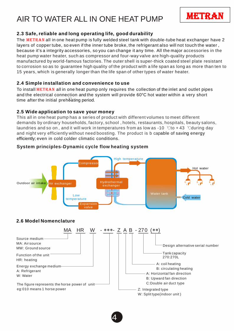
System principles-Dynamic cycle flow heating system
Compressor
High temperature
Hot water
Outdoor air intake Air exchanger
Hydrothermal exchanger
Low temperature
Expansion valve
Water tank Cold water
2.6 Model Nomenclature
MA HR W - - Z A B - 27 0 ( )
Source medium
MA: Air source
MW: Ground source
Function of the unit
HR: heating
Energy exchange medium
A: Refrigerant
W: Water
The figure represents the horse power of unit
eg:010 means 1 horse power
Design alternative serial number
Tank capacity 270:270L
A: coil heating
B: circulating heating
A: Horizontal fan direction
B: Upward fan direction
C:Double air duct type
Z: Integrated type
W: Split type(indoor unit )
AIR TO WATER ALL IN ONE HEAT PUMP
5
metran
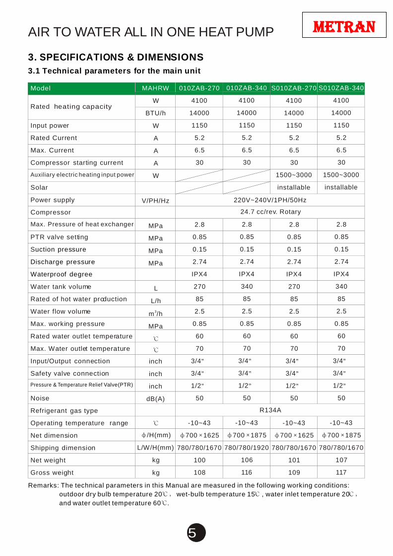
3. SPECIFICATIONS & DIMENSIONS
3.1 Technical parameters for the main unit
Model MAHRW 010ZAB-270 010ZAB-340 S010ZAB-270 S010ZAB-340
Rated heating capacity
W 4100 4100 4100 4100
BTU/h 14000 14000 14000 14000
Input power W 1150 1150 1150 1150
Rated Current A 5.2 5.2 5.2 5.2
Max. Current A 6.5 6.5 6.5 6.5
Compressor starting current A 30 30 30 30
Auxiliary electric heating input power W 1500~3000 1500~3000
Solar installable installable
Power supply V/PH/Hz 220V~240V/1PH/50Hz
Compressor 24.7 cc/rev. Rotary
Max. Pressure of heat exchanger MPa 2.8 2.8 2.8 2.8
PTR valve setting
MPa 0.85 0.85 0.85 0.85
Suction pressure
MPa 0.15 0.15 0.15 0.15
Discharge pressure
MPa 2.74 2.74 2.74 2.74
Waterproof degree IPX4 IPX4 IPX4 IPX4
Water tank volume
L 270 340 270 340
Rated of hot water production
L/h 85 85 85 85
Water flow volume
m3/h 2.5 2.5 2.5 2.5
Max. working pressure
MPa 0.85 0.85 0.85 0.85
Rated water outlet temperature 60 60 60 60
Max. Water outlet temperature 70 70 70 70
Input/Output connection inch 3/4 3/4 3/4 3/4
Safety valve connection inch 3/4 3/4 3/4 3/4
Pressure & Temperature Relief Valve(PTR) inch 1/2 1/2 1/2 1/2
Noise dB(A) 50 50 50 50
Refrigerant gas type R134A
Operating temperature range -10~43 -10~43 -10~43 -10~43
Net dimension /H(mm) 700 1625 700 1875 700 1625 700 1875
Shipping dimension L/W/H(mm) 780/780/1670 780/780/1920 780/780/1670 780/780/1670
Net weight kg 100 106 101 107
Gross weight kg 108 116 109 117
Remarks: The technical parameters in this Manual are measured in the following working conditions:
outdoor dry bulb temperature 20 wet-bulb temperature 15 , water inlet temperature 20
and water outlet temperature 60 .
AIR TO WATER ALL IN ONE HEAT PUMP
6
metran
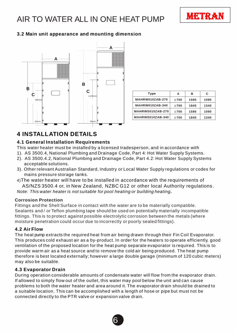
Type A B C
MAHRW010ZAB-270 700 1595 1090
MAHRW010ZAB-340 700 1845 1340
MAHRWS010ZAB-270 700 1595 1090
MAHRWS010ZAB-340 700 1845 1340
3.2 Main unit appearance and mounting dimension
A
A
B
C 885mm
B
C 1135mm
30mm 30mm
4 INSTALLATION DETAILS
4.1 General Installation Requirements This water heater must be installed by a licensed tradesperson, and in accordance with
1). AS 3500.4, National Plumbing and Drainage Code, Part 4: Hot Water Supply Systems.
2). AS 3500.4.2, National Plumbing and Drainage Code, Part 4.2: Hot Water Supply Systems
acceptable solutions.
3). Other relevant Australian Standard, Industry or Local Water Supply regulations or codes for
mains pressure storage tanks.
4)The water heater will have to be installed in accordance with the requirements of
AS/NZS 3500.4 or, in New Zealand, NZBC G12 or other local Authority regulations. Note: This water heater is not suitable for pool heating or building heating.
Corrosion Protection
Fittings and the Shell Surface in contact with the water are to be materially compatible.
Sealants and / or Teflon plumbing tape should be used on potentially materially incompatible
fittings. This is to protect against possible electrolytic corrosion between the metals (where
moisture penetration could occur due to incorrectly or poorly sealed fittings).
4.2 Air Flow The heat pump extracts the required heat from air being drawn through their Fin Coil Evaporator.
This produces cold exhaust air as a by-product. In order for the heaters to operate efficiently, good
ventilation of the proposed location for the heat pump separate evaporator is required. This is to
provide warm air as a heat source and to remove the cold air being produced. The heat pump
therefore is best located externally; however a large double garage (minimum of 120 cubic meters)
may also be suitable.
4.3 Evaporator Drain During operation considerable amounts of condensate water will flow from the evaporator drain.
If allowed to simply flow out of the outlet, this water may pool below the unit and can cause
problems to both the water heater and area around it. The evaporator drain should be drained to
a suitable location. This can be accomplished with a length of hose or pipe but must not be
connected directly to the PTR valve or expansion valve drain.
AIR TO WATER ALL IN ONE HEAT PUMP
7
metran
4.4 Pressure & Temperature Relief Valve (PTR) The Pressure and Temperature relief valve, which is supplied with the unit, must be fitted and
made accessible so that the release mechanism can be operated and, if required, the valve
replaced. The outlet of the PTR valve must be suitably drained to remove the water discharged
during the normal heating cycle. The valve thread is G1/2 /20mm and must be installed into the
connection point as indicated on the tank.
Warning:
A separate drain line must be run for this relief valve. It is not permitted to couple the drain lines
from the relief valve and evaporator into a single common line. The use of a tundish under the
evaporator drain with this then connected to the drain of the PTR valve is acceptable.
Following installation The valve lever MUST be operated AT LEAST ONCE A YEAR by the hot water tank owner to ensure that the water-ways are clear. Certain naturally occurring mineral deposits may adhere to the valve, rendering it inoperative. When manually operating the lever, water will discharge and precautions must be taken to avoid contact with hot water and to avoid water damage. BEFORE operating lever, check to see that a discharge line is connected to this valve directing the flow of hot water from the valve to a proper place of disposal otherwise personal injury may result. If no water flows, valve is inoperative. TURN OFF THE WATER HEATER AND CALL A PLUMBER IMMEDIATELY. This device is designed for emergency safety relief and shall not be used as an operating control.
IMPORTANT: INQUIRE WITH GOVERNING AUTHORITIES FOR LOCAL INSTALLATION
REQUIREMENTS AND FOLLOW THESE REGULATIONS CAREFULLY.
4.5 Expansion Control Valve (ECV) Where an Expansion Control Valve is fitted to the cold water supply, the ECV should be rated at
150kPa lower than the Pressure & Temperature Relief valve (PTR). It is a State requirement for
SA & QLD that an ECV be fitted on the cold water supply line between the non- return valve and
the water heater.
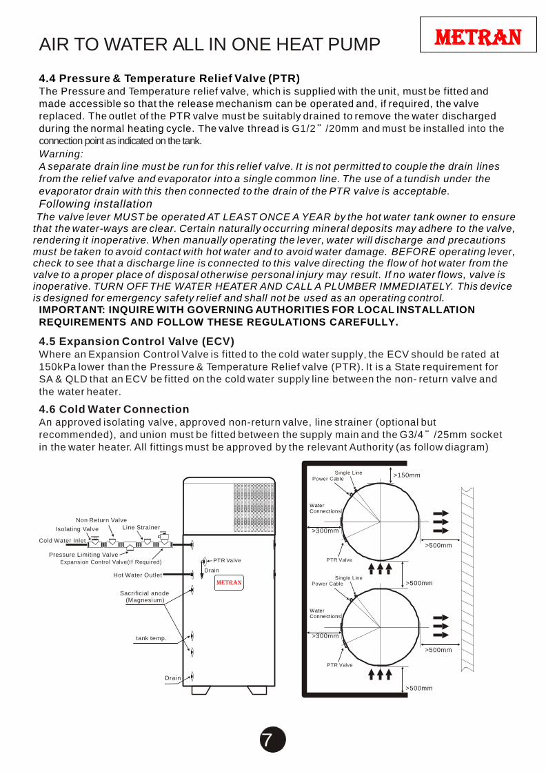
4.6 Cold Water Connection An approved isolating valve, approved non-return valve, line strainer (optional but
recommended), and union must be fitted between the supply main and the G3/4 /25mm socket
in the water heater. All fittings must be approved by the relevant Authority (as follow diagram)
Single Line >150mm
Power Cable
Non Return Valve
Water Connections
Isolating Valve
Cold Water Inlet
Pressure Limiting Valve
Line Strainer >300mm
>500mm
Expansion Control Valve(If Required)
Hot Water Outlet
Sacrificial anode
(Magnesium)
PTR Valve
Drain
metran
PTR Valve
Single Line
Power Cable
Water Connections
>500mm
tank temp. >300mm
>500mm
PTR Valve
Drain
>500mm
AIR TO WATER ALL IN ONE HEAT PUMP
8
metran
4.7 Pressure Reducing Valve This water heater is designed for direct connection to a maximum water supply pressure of
600kpa. Where the mains pressure exceeds this or fluctuate beyond this pressure, a pressure-
limiting device (complying with AS1357) must be fitted in the cold-water supply line. This device
must be installed after the isolating valve and set at or below 500kPa (or 350kPa if a 600kPa
expansion control valve fitted). An ECV is fitted when the water supply has a tendency for form
scale. This type of water is referred to as scaling water because calcium carbonate is deposited
out of the water onto any hot metallic surface. The fitting of an ECV is mandatory in WA, SA and
some other areas of Australia as dictated by local regulations.
4.8 Suitability for Installation The R134a refrigerant used has a boiling point of 26 so there is no risk of damage to the
heat pump from frost. Performance may be reduced in very low temperatures but the system will
not be damaged by such climatic conditions. The unit should be installed at outdoor or open place
and installed base for concrete structure ,also can be use the angle steel bracket and add rubber
cushion on the ground or house roof for shockproof, and ensure the unit in a horizontal position.
4.9 Draining Of Tank Consideration should be given to the possible necessity of draining the tank at some point.
Draining of the tank can be accomplished by the connection of a hose to the cold water inlet and
running to a suitable drain. It will be necessary to disconnect the hot water outlet or PTR valve to
the expansion of water during heating and relieve any partial vacuum created as the water flows
out.
4.10 Hot Water Connection The hot water pipe should be connected to the G3/4”/ 25mm socket as shown in the Installation
Diagram. NOTE: Plugs are supplied with the water heater to plug off the inlet / outlet entries that
are not required. Ensure that adequate sealing tape is applied to the plugs for a tight, leak proof
seal.
4.11 Tempering Valves
Where a tempering valve is fitted on the hot water outlet of a metran (to reduce water
temperature to 50 as per the plumbing code) ONLY high performance valves suitable for Solar
type water heaters are recommended to be used. Standard tempering valves may not function
correctly.
4.12 Electrical Connection
metran water heaters are designed for single-phase 220/240V A.C supply only. A certified
electrician must carry out all electrical work according to the local supply authority regulations
and AS3000. A 15-amp circuit breaker must be installed at the power supply for the hot water unit.
A separate circuit breaker is recommended for each unit in the case of multiple installations. The
power connection rating is 220-240VAC 50Hz 15A. 60 Hz Models are also available on request.
It is not recommended to wire the system to an earth leakage circuit breaker. There is lot of
moisture present while in operation and this can lead to nuisance tripping.
The connection will require an approved, standard 240V 15A On / Off switch or Junction Box in
close proximity to the heater. The unit should be connected to Standard Domestic tariff. Off Peak
connection is NOT recommended for metran heat pump units. If the unit is connected to an Off
Peak tarrif, the minimum power availability must be at least 18 hours per day. The fitted power cord is not to be removed; this cord should be connected with the building wiring in an On / Off switch enclosure or Junction Box. Faulty wiring may void the warranty if damage has been sustained to the compressor or heat pump from such faulty or sub-standard wiring.
AIR TO WATER ALL IN ONE HEAT PUMP
9
metran
Safety Notes
Note.1: This water heater is fitted with a thermostat and over-temperature energy cut-out (both
incorporated into the digital controller). Under no circumstances should the water heater be
operated without both of these devices being in the circuit. Only a qualified electrician or the
manufacturer should carry out replacement.
Note.2: If the supply cord is damaged, its local service agent or other similarly qualified person
must replace it in order to avoid hazard.
Caution: The water heater must be filled with water before turning on the electricity
4.13 Caution Regarding Drilling Metal Jacket This is extremely important and MUST be adhered to without exception!
DO NOT DRILL ANY HOLES IN OUTER METAL JACKET IT MAY BE DAMAGE TO WATER LINES MAY RESULT
5. OPERATING INSTRUCTIONS
5.1 Filling the Water Heater Open all hot water taps. Open isolating valve at the cold-water inlet and allow the water heater to
fill until water flows through the system. Close each hot water tap after the air is expelled from it’s
line.
5.2 Air Expelling Of the Circulating Water Pump before Power Up For the First Time After the system is filled with water, keep all the hot water taps and isolating valve at the cold-water inlet open to let the water flow out for a minute, then power up the unit (Or use the digital controller to push the button of ON/ OFF ) to operating unit, if the unit does not stop after 5 minutes, indicating the unit is operating normally, then close the all the hot water taps to let the heat pump start its initial start-up heating cycle. If not, Power off (Or use the digital controller to push button of the ON/ OFF ) , and open the hot water tap again for a minute to let the water flow out, then power up the unit (Or use the digital controller to push the button of ON/ OFF ) to operating unit, if the unit not stop during 5 minute, that means the unit normal operation, then close the all the hot water taps to let the heat pump work normally, Repeat the same process to let the air expelled from the water pump .
5.3 Water Quality
Your metran water heater has been manufactured to suit the water conditions of most
Australian metropolitan supplies. Please note that harsh water supplies can have a detrimental
effect on the water heater and its life expectancy. If you are unsure about your water quality you
can obtain information from your local water supply authority. The PH of water is 7.2--7.6 which is
better for human consumption.
By using the correct anode this water heater can be used in areas where the Total Dissolved
Solids (TDS) content of the water supply is up to 2500 mg/L. In areas where the TDS exceeds
750mg/L it is possible that the magnesium alloy anode (supplied in the heater) may become over
reactive. To alleviate this, the magnesium alloy anode should be replaced with an aluminum alloy
anode (Note: metran only supplies the anode in the vitreous enamel lined steel cylinder
products).
5.4 Caution When Left Operating but Unused If the water heater is left in an operating condition but unused for two weeks or more, a quantity of
hydrogen gas (which is highly flammable) may accumulate in the top of the water cylinder. To
dissipate this gas safely it is recommended that a hot tap be turned on for several minutes at a sink,
basin or bath, but not a dishwasher, clothes washer or other appliance. During this procedure there
must be no smoking, open flame or any other electrical appliance operating nearby. If hydrogen
gas is discharged through the tap it will probably make an unusual sound similar to air escaping.
AIR TO WATER ALL IN ONE HEAT PUMP
10
metran
6. SAFETY INFORMATION 6.1 Safety Devices WARNING: For safe performance this water heater is fitted with:
1). Digital Controller. 2). A thermostat (connected to the digital controller) to manage water temperature. 3). A thermostat (connected to the digital controller) to manage compressor temperature. 4). A non self-setting thermal cut out (incorporated into the digital controller). 5). Combination Pressure & Temperature relief valve.
These devices must not be tampered with or removed. The water heater must not be operated unless each of these devices is fitted and in working
order. This appliance is not intended for use by persons (including children) with reduced physical,
sensory or mental capabilities, or lack of experience and knowledge, unless they have been given supervision or instruction concerning use of the appliance by a person responsible for their safety. Children should be supervised to ensure that they do not play with the appliance
6.2 Important Note Regarding PTR Valve The Pressure & Temperature relief valve should be checked for adequate performance or
replaced at intervals not exceeding 5 years, or less in areas where there is a high incidence of
water deposits. Providing there is some discharge from the relief valve during each heating cycle
there is no requirement to manually activate the release mechanism on the relief valve. There is
a possibility that manually opening the relief valve may allow contamination / grit etc to settle in
the valve seat causing continuous leakage. If the relief valve is operated manually it should be
done with care.
The Pressure & Temperature relief valve and the drain outlet pipe must not be sealed or blocked.
It is normal for small amounts of water to leak from the valve during each heating cycle.
DO NOT TURN ON POWER UNLESS THE TANK IS FULL OF WATER
7. MAINTAINANCE & SERVICE INFORMATION Your metran water heater is a completely sealed refrigeration system, similar to a household
refrigerator. The maintenance program to be employed on your metran is not much different to
that required for the maintenance of a standard electric water heater. However, metran warranty
may be void if any of the following conditions are not met or if the refrigeration lines or
components are damaged or altered in any unauthorized way.
7.1 The Water Tank The water tank must not be drilled or punctured. Drilled holes or punctures, may damage the
water pipes located in the water tank.
7.2 Air Evaporator Coils
metran water heaters use evaporator coils to extract heat from the air. The coil is extremely
efficient in warm humid weather; however, as temperatures drop to ten degrees or less the coil
will begin to collect ice. The coil has been designed with auto-defrost for the coil under such
conditions. The defrost is automatic and is managed by the digital controller. It is important that
the air inlet vents are kept clean. Restriction of air-inlet or outlet vents may void warranty if the
system has been damaged because of insufficient airflow.
7.3 Sacrificial Anode A sacrificial anode is fitted inside the vitreous enamel lined cylinder. Its purpose is to help protect
the cylinder from the corrosive effects of water. Normally, the sacrificial anode should be inspected
every fifth year and replaced if necessary. In areas where hard water or where poor quality water
conditions exist, the sacrificial anode must be inspected every second year. Replacement
anodes must meet metran quality specifications and must be appropriate for local water
conditions. The anode socket in the tank can be either a ½” or ¾” connection.

AIR TO WATER ALL IN ONE HEAT PUMP
11
metran
7.4 Service Caution Before Any Work Is Carried Out Before any electrical components are inspected the System MUST be turned off at the power
switch / hot water circuit breaker. Do not touch wiring or any electrical components without
supervision or training to Australian (or equivalent) standards.
7.5 Thermal Overload (Incorporated in Digital Controller) All models are fitted with a digital controller for heat pump management. One function of the
digital controller is to initiate a shut down and lockout if the compressor reaches a temperature
of 105 . The system will not automatically restart from this. Turning the power off then back on
will also perform a reset.
7.6 Routine Service
7.6a Access & Removal of Sacrificial Anode
The anode can be accessed via the heat pump section, to remove.
1). Turn off power to the unit, cut into water valve, open PTR valve to release pressure on the system.
2). The anode head is now accessible and can be unscrewed with a suitable socket wrench.
3). Once unscrewed the anode can be drawn out through the flank of the tank / heat pump section.
4). The new anode can then be fitted and the heater reassembled.
7.6b Flushing of Water Tank
As with other hot water heater tanks, dissolved solids in the water or scale may accumulate in
the bottom of the water tank forming sludge. This is generally less of a problem with metran units
as no internal elements or burners are used.
If such sludge build-up does occur the following procedure can be followed to clean out the tank.
1). Turn Off power to the unit.
2). Turn Off water supply to the unit.
3). Remove the blanking plug (brass fitting) from the unused inlet (normally on the right hand side
for left hand connected tanks) the inlets are at the bottom of the tank about 300mm up from the
base.
4). Remove the blanking plug from the unused hot water outlet (normally on the right hand side
for left hand connected tanks) the outlets are at the top of the tank.
5). Allow the water to drain from tank, while the water is draining a non-metallic rod may be inserted
through the open cold-water inlet and used to break up any sludge and assist in its removal.
6). Turning the cold water supply back on while the tank is emptying or after the tank has drained
and continuing with the mechanical agitation will further assist with the removal of the sludge.
8. OPERATION & ADJUSTMENT OF THE DIGITAL CONTROLLER Caution:
Alteration of the Digital Controllers programming & settings without authorization from metran
International Pty. Ltd. will void your warranty. This section is provided ONLY for qualified
refrigeration technicians to assist in servicing, repairs or trouble shooting.
8.1 Mounting and fixing method of the remote controller:
AIR TO WATER ALL IN ONE HEAT PUMP
12
metran
2 2
Illustration 1 Illustration 2
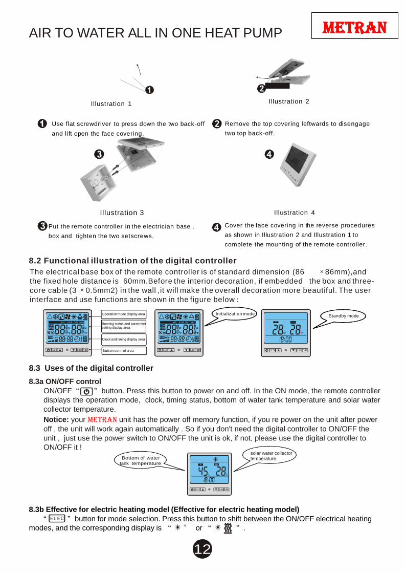
Use flat screwdriver to press down the two back-off
and lift open the face covering.
Remove the top covering leftwards to disengage
two top back-off.
Illustration 3 Illustration 4
Put the remote controller in the electrician base .
box and tighten the two setscrews.
Cover the face covering in the reverse procedures
as shown in Illustration 2 and Illustration 1 to
complete the mounting of the remote controller.
8.2 Functional illustration of the digital controller
The electrical base box of the remote controller is of standard dimension (86 86mm),and
the fixed hole distance is 60mm.Before the interior decoration, if embedded the box and three-
core cable (3 0.5mm2) in the wall ,it will make the overall decoration more beautiful. The user
interface and use functions are shown in the figure below
Operation mode display area Initialization mode Standby mode
Running status and parameter setting display area
IN O UT
1 Clock and timing display area 1
Button control area
8.3 Uses of the digital controller
8.3a ON/OFF control
ON/OFF button. Press this button to power on and off. In the ON mode, the remote controller
displays the operation mode, clock, timing status, bottom of water tank temperature and solar water
collector temperature.
Notice: your metran unit has the power off memory function, if you re power on the unit after power
off , the unit will work again automatically . So if you don't need the digital controller to ON/OFF the
unit , just use the power switch to ON/OFF the unit is ok, if not, please use the digital controller to
ON/OFF it !
Bottom of water tank temperature
solar water collector temperature.
8.3b Effective for electric heating model (Effective for electric heating model)
button for mode selection. Press this button to shift between the ON/OFF electrical heating
modes, and the corresponding display is or .
AIR TO WATER ALL IN ONE HEAT PUMP
13
metran
OUT
Water heating mode
OUT
Manual mode for electric-heating is on
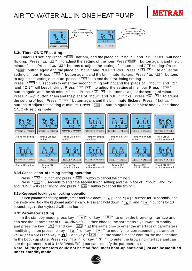
8.3c Timer ON/OFF setting.
Timer ON setting: Press bottom, and the place of hour and 1 ON will keep
flicking. Press to adjust the setting of the hour. Press button again, and the bit
minute flicks. Press buttons to adjust the setting of minute; timed OFF setting: Press
button again and the place of hour and OFF flicks. Press to adjust the
setting of hour. Press button again, and the bit minute flickers. Press buttons
to adjust the setting of minute. press to end the first timing setting.
Press 3 seconds to enter the second timing setting; and the place of hour and 2
and ON will keep flicking. Press to adjust the setting of the hour. Press
button again, and the bit minute flicks. Press buttons to adjust the setting of minute;
Press button again and the place of hour and OFF flicks. Press to adjust
the setting of hour. Press button again, and the bit minute flickers. Press
buttons to adjust the setting of minute. Press button again to complete and exit the timed
ON/OFF setting mode.
Timing ON setting Timing ON hour
setting Timing ON minute setting
Timing ON setting completed
Timing OFF hour s etting
Timing OFF minute setting
Timed ON/OFF setting completed
Timing ON setting Timing ON Timing ON Timing ON Timing OFF Timing OFF Timed ON/OFF
hour setting minute setting setting completed hour setting minute setting setting completed
8.3d Cancellation of timing setting operation
Press button and press button to cancel the timing 1. Press 3 seconds to enter the second timing setting; and the place of hour and 2
and ON will keep flicking, and press button to cancel the timing 2.
8.3e Keyboard locking / unlocking operation
In non-parameter setting mode, press and hold down and buttons for 10 seconds, and
the system will lock the keyboard automatically. Press and hold down and buttons for 10
seconds again, the keyboard will be unlocked.
8.3f Parameter setting
In the standby mode, press key or key to enter the browsing interface and
can see the parameters of 0-14/A/b/c/d/E/F , then choose the parameters you want to modify ,
and press the key and key at the same time to enter the interface of parameters
modifying , then press the key or key to modify the corresponding parameter
value ,then press the key and key at the same time for confirm the modification .
In the boot - up state. Press key or key to enter the browsing interface and can
see the parameters of 0-14/A/b/c/d/E/F .( but can't modify the parameters )
Note: All the parameters could not be modified under boot-up state and just can be modified under standby mode.
AIR TO WATER ALL IN ONE HEAT PUMP
14
metran
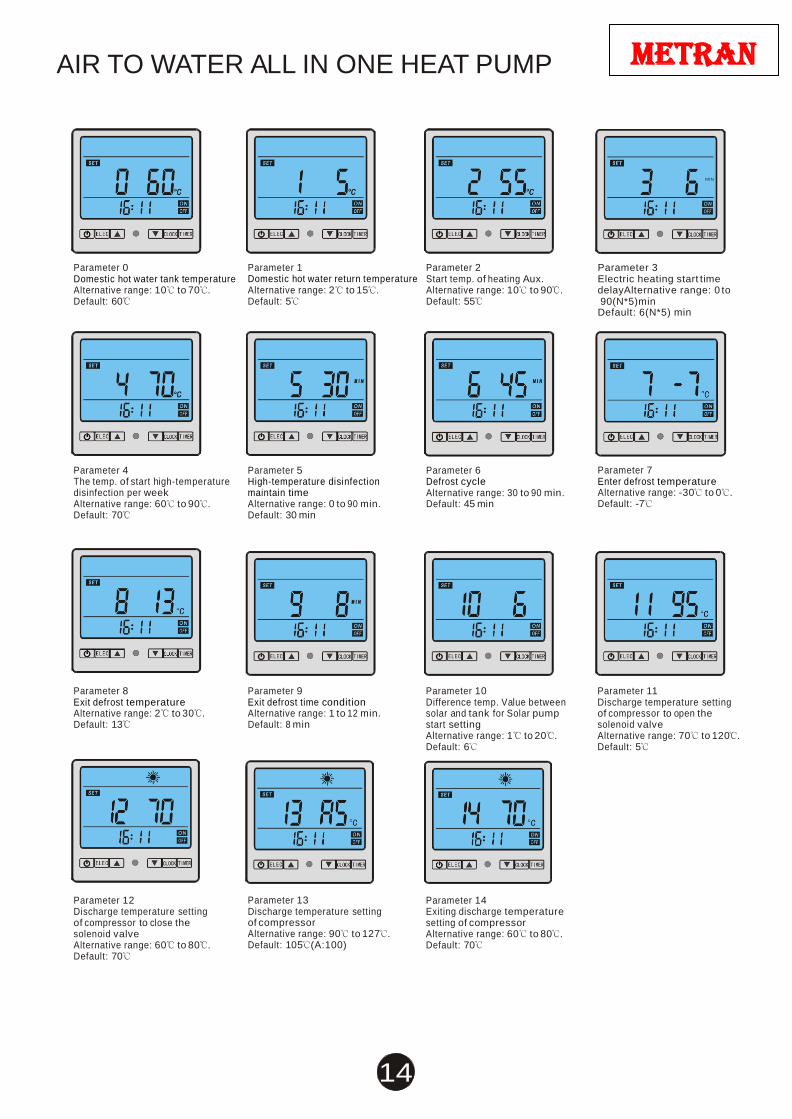
Parameter 0 Domestic hot water tank temperature Alternative range: 10 to 70 . Default: 60
Parameter 4 The temp. of start high-temperature disinfection per week Alternative range: 60 to 90 . Default: 70
Parameter 1 Domestic hot water return temperature Alternative range: 2 to 15 . Default: 5
Parameter 5 High-temperature disinfection maintain time Alternative range: 0 to 90 min. Default: 30 min
Parameter 2 Start temp. of heating Aux. Alternative range: 10 to 90 . Default: 55
Parameter 6 Defrost cycle Alternative range: 30 to 90 min. Default: 45 min
MIN
Parameter 3 Electric heating start time delayAlternative range: 0 to 90(N*5)min Default: 6(N*5) min
Parameter 7 Enter defrost temperature Alternative range: -30 to 0 . Default: -7
Parameter 8 Exit defrost temperature Alternative range: 2 to 30 . Default: 13
Parameter 12 Discharge temperature setting of compressor to close the solenoid valve Alternative range: 60 to 80 . Default: 70
Parameter 9 Exit defrost time condition Alternative range: 1 to 12 min. Default: 8 min
Parameter 13 Discharge temperature setting of compressor Alternative range: 90 to 127 . Default: 105 (A:100)
Parameter 10 Difference temp. Value between solar and tank for Solar pump start setting Alternative range: 1 to 20 . Default: 6
Parameter 14 Exiting discharge temperature setting of compressor Alternative range: 60 to 80 . Default: 70
Parameter 11 Discharge temperature setting of compressor to open the solenoid valve Alternative range: 70 to 120 . Default: 5
AIR TO WATER ALL IN ONE HEAT PUMP
15
metran
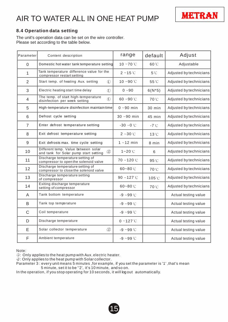
8.4 Operation data setting
The unit's operation data can be set on the wire controller. Please set according to the table below.
Parameter
Content description range default Adjust
0 Domestic hot water tank temperature setting 10 70 60 Adjustable
1 Tank temperature difference value for the compressor restart setting
2 15 5 Adjusted by technicians
2 Start temp. of heating Aux. setting 1 10 90 55 Adjusted by technicians
3 Electric heating start time delay 1 0 90 6(N*5) Adjusted by technicians
4 The temp. of start high-temperature disinfection per week setting
1
60 90 70 Adjusted by technicians
5 High-temperature disinfection maintain time 0 90 min
30 min Adjusted by technicians
6 Defrost cycle setting 30 90 min
45 min Adjusted by technicians
7 Enter defrost temperature setting -30 0
-7 Adjusted by technicians
8 Exit defrost temperature setting 2 30
13 Adjusted by technicians
9
Exit defrosts max. time cycle setting 1 12 min
8 min Adjusted by technicians
10 Different temp. Value between solar and tank for Solar pump start setting 1~20
6 Adjusted by technicians
11 Discharge temperature setting of compressor to open the solenoid valve
70 120
95 Adjusted by technicians
12 Discharge temperature setting of compressor to close the solenoid valve
60~80
70 Adjusted by technicians
13 Discharge temperature setting of compressor
90 127
105
Adjusted by technicians
14 Exiting discharge temperature setting of compressor
60~80
70
Adjusted by technicians
A Tank bottom temperature
-9 99
Actual testing value
B Tank top temperature
-9 99
Actual testing value
C Coil temperature
-9 99
Actual testing value
D
Discharge temperature
0 127
Actual testing value
E Solar collector temperature
-9 99
Actual testing value
F Ambient temperature
-9 99
Actual testing value
Note:
: Only applies to the heat pump with Aux. electric heater. : Only applies to the heat pump with Solar collector.
Parameter 3 : every unit means 5 minutes ,for example, if you set the parameter is '1' ,that's mean 5 minute, set it to be ''2', it's 10 minute, and so on.
In the operation, if you stop operating for 10 seconds, it will log out automatically.
AIR TO WATER ALL IN ONE HEAT PUMP
16
metran
8.5. Time Delay on Start
NOTE: The system has a 3-minute time delay on restart. When the power is after a disconnection then re connection, the time delay on start will commence. The compressor and fan will not operate until the completion of this delay period.
9. RECOGNITION OF ABNORMAL OPERATION
9.1 Pressure & Temperature Relief Valve Running It is not unusual for the Pressure & Temperature Relief valve to allow a small quantity of water to
escape during the heating cycle. The amount of discharge will depend on hot water usage. As
a guide, if it discharges more than 20 litres of water in 24 hours then there may be a problem.
9.1a Continuous Trickle
Likely build up of foreign matter. Try gently operating the release mechanism on the Pressure & Temperature Relief valve for a few seconds. This may dislodge any small particles of foreign matter and rectify the fault. 9.1b Steady Flow
Likely causes are excessive water supply pressure (500kPa Pressure Limiting valve should be
fitted), a faulty Pressure & Temperature Relief valve, a faulty or no pressure limiting valve or a
faulty Thermostat / Digital Controller. Turn off the electricity supply and contact your metran
distributor or service agent.
9.2 No Hot Water
1). Check if the Electricity switched on? Check that the isolating switch, to which the metran Unit is connected, is on. Check that the switch marked Water Heater in the
switchboard is on. Are all circuit breakers on? If on Off Peak, is the meter switching on when it
should? Note if the system is connected to any form of Off Peak, running out of hot water can be
quite common Off Peak tariffs are not recommended for metran water heaters.
2). Check that the thermal overload (on the digital controller) has not been tripped. Turning
the power off then back on will also perform a reset.
3). Check if the Pressure & Temperature Relief valve discharging too much water? See "Pressure & Temperature Relief Valve Running".
4). Do you have the correct size water heater for your requirements? Sizing details are
available from your metran supplier.
5). Check if one outlet (such as the shower) is using more hot water than you think?
Carefully review the family's hot water usage and if necessary check the shower flow rates with
a bucket and a watch. If it is not possible to adjust water usage patterns, an inexpensive flow
control valve can easily be fitted to the shower outlet.
AIR TO WATER ALL IN ONE HEAT PUMP
17
metran
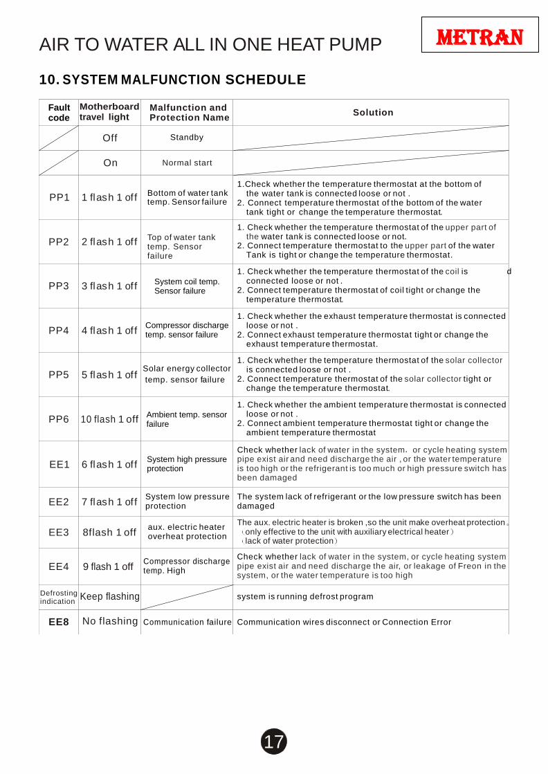
Fault code
Motherboard travel light
Malfunction and Protection Name
Solution
Off
Standby
On
Normal start
PP1
1 fl as h 1 of f
Bottom of water tank temp. Sensor failure
1.Check whether the temperature thermostat at the bottom of the water tank is connected loose or not .
2. Connect temperature thermostat of the bottom of the water tank tight or change the temperature thermostat.
PP2
2 fl as h 1 of f
Top of water tank temp. Sensor failure
1. Check whether the temperature thermostat of the upper part of the water tank is connected loose or not.
2. Connect temperature thermostat to the upper part of the water Tank is tight or change the temperature thermostat.
PP3
3 fl as h 1 of f
System coil temp. Sensor failure
1. Check whether the temperature thermostat of the coil is connected loose or not .
2. Connect temperature thermostat of coil tight or change the temperature thermostat.
PP4
4 fl as h 1 of f
Compressor discharge temp. sensor failure
1. Check whether the exhaust temperature thermostat is connected loose or not .
2. Connect exhaust temperature thermostat tight or change the exhaust temperature thermostat.
PP5
5 fl as h 1 of f
Solar energy collector
temp. sensor failure
1. Check whether the temperature thermostat of the solar collector is connected loose or not .
2. Connect temperature thermostat of the solar collector tight or change the temperature thermostat.
PP6
10 flash 1 off
Ambient temp. sensor failure
1. Check whether the ambient temperature thermostat is connected loose or not .
2. Connect ambient temperature thermostat tight or change the ambient temperature thermostat
EE1
6 fl as h 1 of f
System high pressure protection
Check whether lack of water in the system or cycle heating system pipe exist air and need discharge the air , or the water temperature is too high or the refrigerant is too much or high pressure switch has been damaged
EE2
7 fl as h 1 of f System low pressure protection
The system lack of refrigerant or the low pressure switch has been damaged
EE3
8flash 1 off
aux. electric heater overheat protection
The aux. electric heater is broken ,so the unit make overheat protection only effective to the unit with auxiliary electrical heater lack of water protection
EE4
9 flash 1 off
Compressor discharge temp. High
Check whether lack of water in the system, or cycle heating system pipe exist air and need discharge the air, or leakage of Freon in the system, or the water temperature is too high
Defrosting indication
Keep flashing
system is running defrost program
EE8
No flashing Communication failure
Communication wires disconnect or Connection Error
10. SYSTEM MALFUNCTION SCHEDULE
d
AIR TO WATER ALL IN ONE HEAT PUMP
18
metran
Se
lf-ch
eck k
ey
Tu
rn o
n/o
ff R
un
ind
ica
tor
Re
se
rva
tion
Wire
co
ntro
ller
So
lar c
ircu
latin
g
wa
ter p
um
p
Hig
h p
ressu
re s
witc
h
Lo
w p
res
su
r e s
witc
h
Ove
r he
atin
g p
rote
ctio
n
Blu
e
Blu
e
Blu
e
Bla
ck
B
lue
Blu
e
Re
d
Wh
ite
B
row
n
Blu
e
11. JUDGEMENT AND SOLUTION OF MALFUNCTIONS
Malfunction Reason Solution
Unit does
not work
1.Power failure
2.Loose power wire connection
3.Fuse of controller burn-out
1.Turn off power and inspect power supply
2.Identify the cause and rectify
3.Identify the cause and replace with new fuse
The pump is
operating, but
water isn't
circulatory or the
noise of pump is
to loud
1. Shortage of the water or exist air
in the water system.
2.Water pump damage
3.Valve of water system is not all opened
4.Water filter is blocked
1.Check water supply equipment and replenish
water remove the air of the water system
2. Change to another pump.
3.Open the valve of the water system
4.Clean the water filter and the pump
Unit heating
capacity is low or
compressor
long term working
1.Shortage of refrigerant or leakage
2.Poor thermal insulation of water system
3.Poor heat dissipation of the air heat exchanger
4.Shortage of water flow
1.Check the system for leakage and fill refrigerant
2.Strengthen thermal insulation of the system pipeline
3.Clean the air heat exchanger and improve the
condensation condition
4.Clean the filter
Compressor
discharge pressure
too high
1.Excessive refrigerant
2.Poor cooling capacity of air heat exchanger
1.Release the excess refrigerant
2.Clean the air heat exchanger and improve
condensation conditions
Compressor
suction pressure
too low
1.Shortage of refrigerant or leakage
2.Filter or capillary blocked
3.Poor condenser heat dissipation
1.Check the system for leakage and fill refrigerant
2.Replace capillary tube or filter
3. Clean the heat exchanger.
Compressor is
out off
operation
1.Power failure
2.Compressor contactor breaks down
3.Loose connection
4.Overload protection of compressor
5.Incorrect setting of the return water
temperature in the water tank
6.Compressor capacitance break down
1.Check the power supply and debug
2.Replace the contactor
3. Check the loose place and maintenance it.
4. Overload protection of the compressor.
5. Reset the return temp.
6. Replace the capacitance.
Loud compressor
noise
1.Liquid refrigerant enters the compressor
2.Compressor breads down
1.Check the cause for liquid impact and solve the problem
2.replace the compressor
Fan is out of
operation 1.The relay or capacitance of the fan breaks down
2.Burnt the fan motor
1.Replace the fan relay or capacitance
2.Replace the fan motor
The compressor
is in operation,
but the unit
doesn't heating
1.All the refrigerants leak out
2.Compressor breaks down
1.Check the system for leakage and fill refrigerant
2.Check the reason and replace the compressor
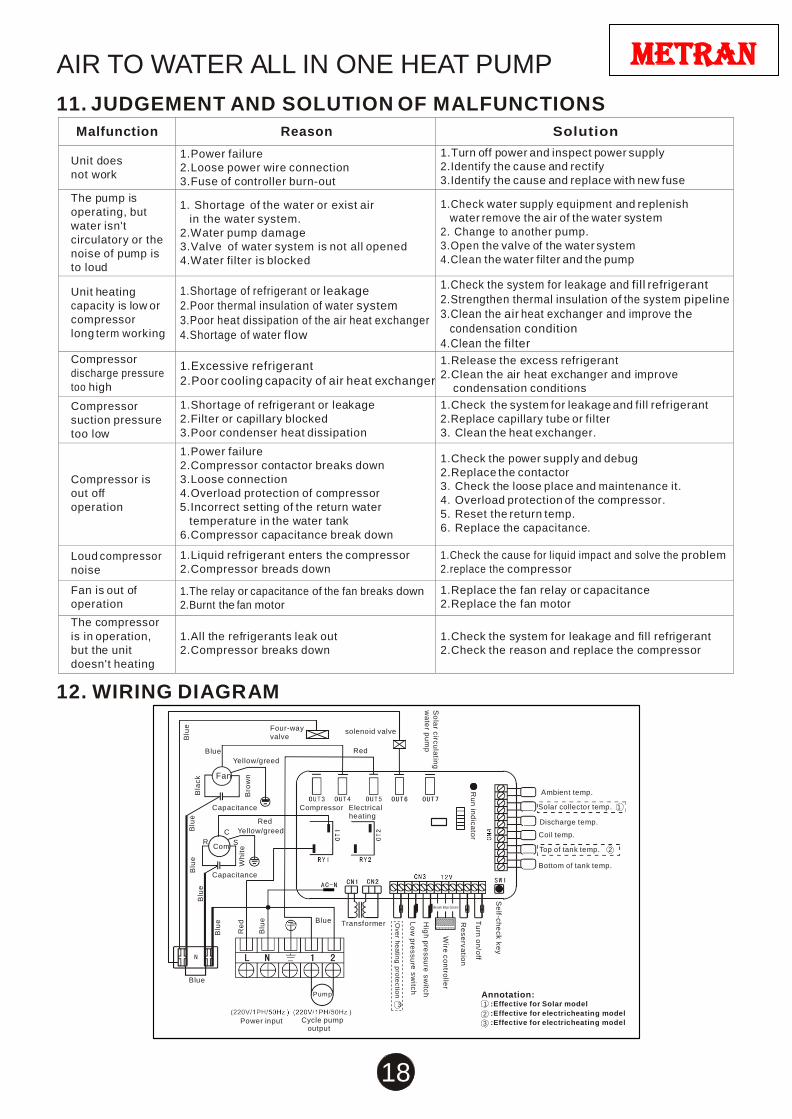
12. WIRING DIAGRAM
Blue
Fan
Four-way valve
Yellow/greed
solenoid valve
Red
Capacitance
Red
Compressor Electrical
heating
Ambient temp.
Solar collector temp. 1
Discharge temp.
C Yellow/greed Coil temp.
R Com
S Top of tank temp. 2
Capacitance
Bottom of tank temp.
Blue Transformer
Brown Blue Green
Blue
Power input
Pump
3 Cycle pump
output
Annotation: 1 :Effective for Solar model
2 :Effective for electricheating model
3 :Effective for electricheating model
CODE:MK3045/MK3058
metran
AIR TO WATER ALL IN ONE HEAT PUMP
Metran International Pty. Ltd.
8 Lochern Court
North Lakes 4509
Queensland – Australia
Email: [email protected]
Website: http://www.metrangroup.com