Embed Size (px)
Citation preview
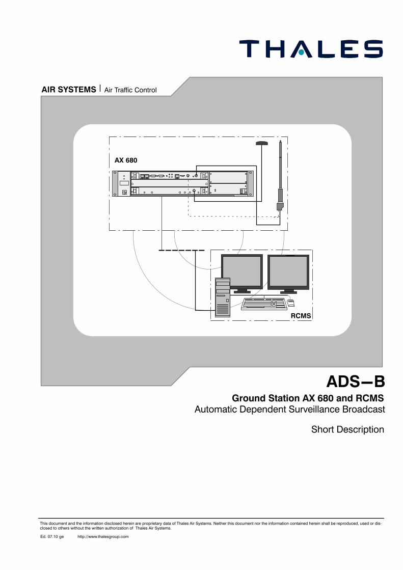
ADS−B
Short Description
Ed. 07.10 ge
This document and the information disclosed herein are proprietary data of Thales Air Systems. Neither this document nor the information contained herein shall be reproduced, used or dis-closed to others without the written authorization of Thales Air Systems.
Ground Station AX 680 and RCMS
http://www.thalesgroup.com
Air Traffic ControlAIR SYSTEMS
RCMS
AX 680
Automatic Dependent Surveillance Broadcast
Conventional NavaidsAIR SYSTEMS
1) Microsoft and MS−DOS are registered trademarks, WINDOWS is a trademark of the Microsoft Corporation. IBM is a registered trademark of the International Business Machines
Corporation. Pentium is a registered trademark of the Intel Corporation. All other mentioned product names may be trademarks of the respective manufacturers and must be
observed.
2) Despite of careful editing work technical inaccuracies and printing faults cannot be excluded in this publication. Change of text remains reserved without notification.
AX 680Short Description System Description
ADS−B
1−1Ed. 07.10
CHAPTER 1SYSTEM DESCRIPTION
1.1 GENERAL
ADS−B is a data link application or principle thatmakes use of navigational data that are avail-able onboard an aircraft. Aircraft avionics per-manently determines the aircraft’s navigationalposition and movement vector. Most air trans-port aircraft are also equipped with a flight man-agement system that guides the aircraft alongwaypoints programmed by the pilot. The princi-ple of ADS−B refers to making this informationavailable by means of an automatic broadcastvia digital data link.
ADS−B is an acronym for Automatic DependentSurveillance Broadcast:
Automatic no human intervention requiredDependent the surveillance solution is not
determined by the observer, butprovided by the observed object
Surveillance data provided include position,velocity vector etc.
Broadcast transmitted without external trigger (e.g. interrogation)without any specific addressee
The broadcast information may be received andprocessed by other aircraft or ground systemsfor use in improved situational awareness, con-flict avoidance and airspace management.Three ADS−B data link technologies are emerg-ing as possible contenders − namely, UniversalAccess Transceiver (UAT), VHF Data Link (VDL)Mode 4 and 1090 MHz Extended Squitter (ModeS data link).
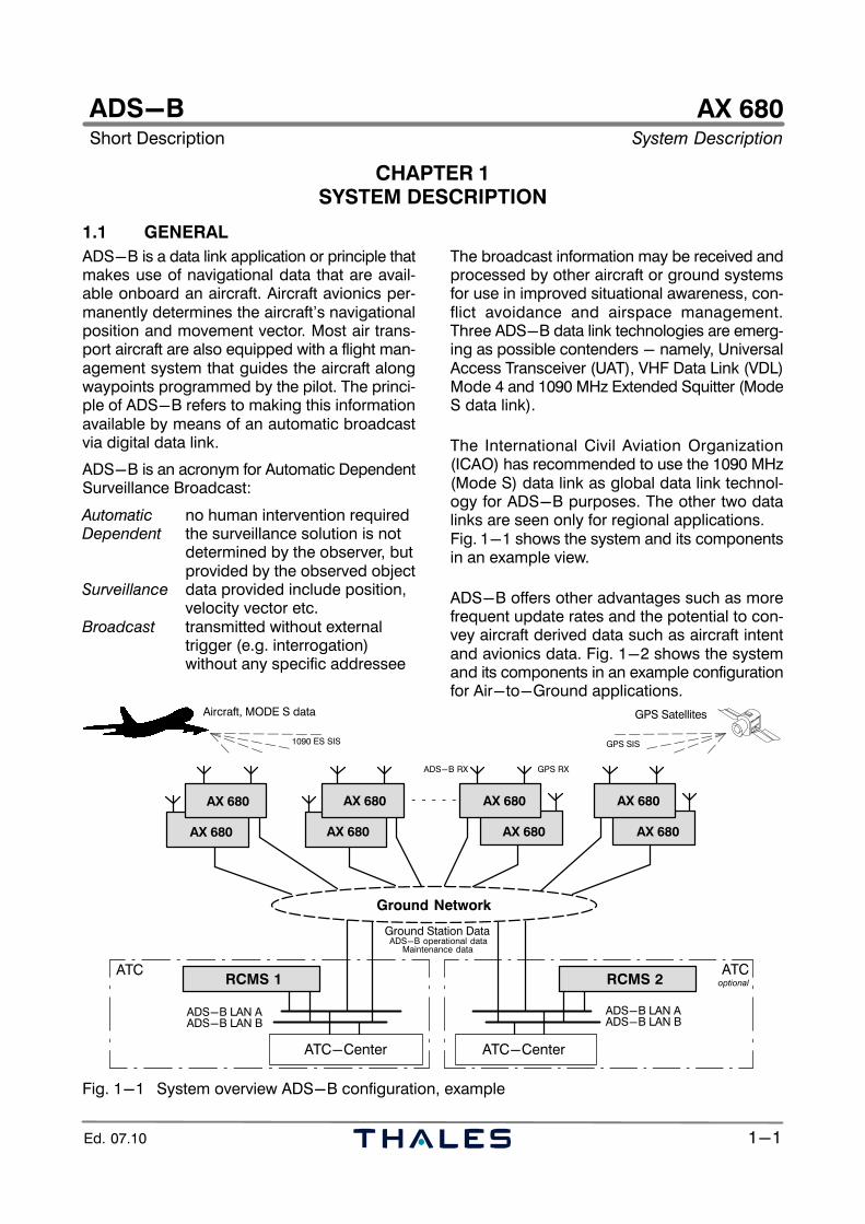
The International Civil Aviation Organization(ICAO) has recommended to use the 1090 MHz(Mode S) data link as global data link technol-ogy for ADS−B purposes. The other two datalinks are seen only for regional applications. Fig. 1−1 shows the system and its componentsin an example view.
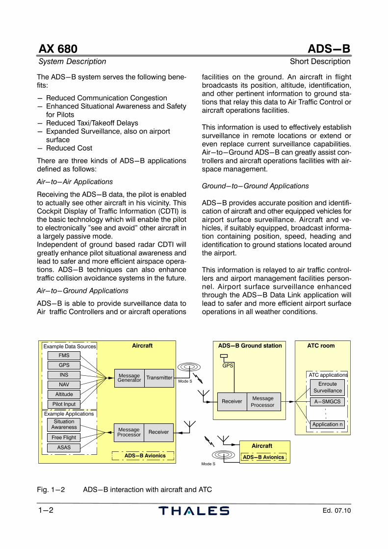
ADS−B offers other advantages such as morefrequent update rates and the potential to con-vey aircraft derived data such as aircraft intentand avionics data. Fig. 1−2 shows the systemand its components in an example configurationfor Air−to−Ground applications.
ADS−B LAN A
RCMS 1
AX 680
Ground Network
RCMS 2
ADS−B LAN BADS−B LAN AADS−B LAN B
ATC−Center ATC−Center
GPS SatellitesAircraft, MODE S data
Ground Station DataADS−B operational data
Maintenance data
1090 ES SIS GPS SIS
ATCATC
ADS−B RX GPS RX
optional
AX 680
AX 680
AX 680
AX 680
AX 680
AX 680
AX 680
Fig. 1−1 System overview ADS−B configuration, example
AX 680System Description Short Description
ADS−B
1−2 Ed. 07.10
The ADS−B system serves the following bene-fits:
− Reduced Communication Congestion − Enhanced Situational Awareness and Safety
for Pilots− Reduced Taxi/Takeoff Delays− Expanded Surveillance, also on airport
surface − Reduced Cost
There are three kinds of ADS−B applicationsdefined as follows:
Air−to−Air Applications
Receiving the ADS−B data, the pilot is enabledto actually see other aircraft in his vicinity. ThisCockpit Display of Traffic Information (CDTI) isthe basic technology which will enable the pilotto electronically "see and avoid" other aircraft ina largely passive mode. Independent of ground based radar CDTI willgreatly enhance pilot situational awareness andlead to safer and more efficient airspace opera-tions. ADS−B techniques can also enhancetraffic collision avoidance systems in the future.
Air−to−Ground Applications
ADS−B is able to provide surveillance data toAir traffic Controllers and or aircraft operations
facilities on the ground. An aircraft in flightbroadcasts its position, altitude, identification,and other pertinent information to ground sta-tions that relay this data to Air Traffic Control oraircraft operations facilities.
This information is used to effectively establishsurveillance in remote locations or extend oreven replace current surveillance capabilities.Air−to−Ground ADS−B can greatly assist con-trollers and aircraft operations facilities with air-space management.
Ground−to−Ground Applications
ADS−B provides accurate position and identifi-cation of aircraft and other equipped vehicles forairport surface surveillance. Aircraft and ve-hicles, if suitably equipped, broadcast informa-tion containing position, speed, heading andidentification to ground stations located aroundthe airport.
This information is relayed to air traffic control-lers and airport management facilities person-nel. Airport surface surveillance enhancedthrough the ADS−B Data Link application willlead to safer and more efficient airport surfaceoperations in all weather conditions.
GPS
INS
NAV
Altitude
Pilot Input
FMS
MessageGenerator
Example Data Sources
Transmitter
MessageProcessor Receiver
SituationAwareness
ASAS
Free Flight
Example Applications
Aircraft
ADS−B Avionics
MessageProcessor
Receiver
ADS−B Ground station
EnrouteSurveillance
Application n
A−SMGCS
ATC applications
ATC room
Aircraft
ADS−B Avionics
GPS
Mode S
Mode S
Fig. 1−2 ADS−B interaction with aircraft and ATC
AX 680Short Description System Description
ADS−B
1−3Ed. 07.10
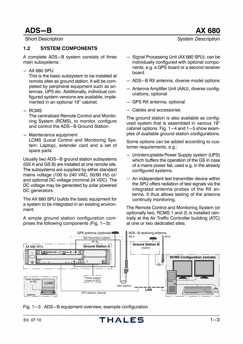
1.2 SYSTEM COMPONENTS
A complete ADS−B system consists of threemain subsystems:
− AX 680 SPUThis is the basic subsystem to be installed atremote sites as ground station. It will be com-pleted by peripheral equipment such as an-tennas, UPS etc. Additionally, individual con-figured system versions are available, imple-mented in an optional 19" cabinet.
− RCMSThe centralized Remote Control and Monito-ring System (RCMS), to monitor, configureand control the ADS−B Ground Station.
− Maintenance equipmentLCMS (Local Control and Monitoring Sys-tem: Laptop), extender card and a set ofspare parts
Usually two ADS−B ground station subsystems(GS A and GS B) are installed at one remote site.The subsystems are supplied by either standardmains voltage (100 to 240 VAC, 50/60 Hz) or/and optional DC voltage (nominal 24 VDC). TheDC voltage may be generated by solar poweredDC generators.
The AX 680 SPU builds the basic equipment fora system to be integrated in an existing environ-ment.
A simple ground station configuration com-prises the following components (Fig. 1−3):
− Signal Processing Unit (AX 680 SPU); can beindividually configured with optional compo-nents, e.g. a GPS board or a second receiverboard.
− ADS−B RX antenna, diverse model options
− Antenna Amplifier Unit (AAU), diverse config-urations, optional
− GPS RX antenna, optional
− Cables and accessories
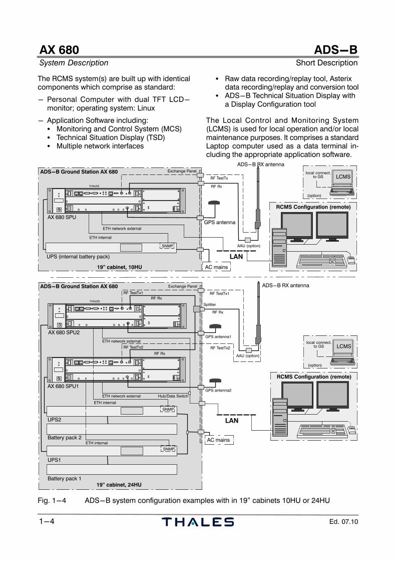
The ground station is also available as config-ured system that is assembled in various 19"cabinet options. Fig. 1−4 and 1−5 show exam-ples of available ground station configurations.
Some options can be added according to cus-tomer requirements, e.g.:
− Uninterruptable Power Supply system (UPS)which buffers the operation of the GS in caseof a mains power fail, used e.g. in the alreadyconfigured systems.
− An independent test transmitter device withinthe SPU offers radiation of test signals via theintegrated antenna probes of the RX an-tenna. It thus allows testing of the antennacontinuity monitoring.
The Remote Control and Monitoring System (oroptionally two, RCMS 1 and 2) is installed cen-trally at the Air Traffic Controller building (ATC)at one or two dedicated sites.
RCMS Configuration (remote)
Ground Station A
GPS antenna (optional) ADS−B receiving antenna
AAU (option)
AX 680 SPU
local connect.
LCMS
RX A
LAN
Ground Station B
to GS
(option)
(option)
Power supply
RX BTest Transmision (option)
ETH network, external
RF Rx
(mains or DC)
Fig. 1−3 ADS−B equipment overview, example configuration
AX 680System Description Short Description
ADS−B
1−4 Ed. 07.10
The RCMS system(s) are built up with identicalcomponents which comprise as standard:
− Personal Computer with dual TFT LCD−monitor; operating system: Linux
− Application Software including:� Monitoring and Control System (MCS)� Technical Situation Display (TSD)� Multiple network interfaces
� Raw data recording/replay tool, Asterixdata recording/replay and conversion tool
� ADS−B Technical Situation Display with a Display Configuration tool
The Local Control and Monitoring System(LCMS) is used for local operation and/or localmaintenance purposes. It comprises a standardLaptop computer used as a data terminal in-cluding the appropriate application software.
ADS−B Ground Station AX 680
GPS antenna
THALES
LAN
19" cabinet, 10HU
AX 680 SPU
RF Rx
ADS−B RX antennaExchange Panel
UPS (internal battery pack)
local connect.LCMS
(option)
to GS
AC mains
RCMS Configuration (remote)
RF TestTx
SNMP
ETH network external
ETH internal
AAU (option)
ADS−B Ground Station AX 680
GPS antenna1
THALES
LAN
19" cabinet, 24HU
AX 680 SPU2
AAU (option)
RF Rx
ADS−B RX antennaExchange Panel
UPS2
local connect.LCMS
(option)
to GS
AC mains
RCMS Configuration (remote)
RF TestTx1
SNMP
ETH network external
GPS antenna2
RF TestTx2
Splitter
RF Rx
RF Rx
RF TestTx1
RF TestTx2
UPS1
ETH network external
AX 680 SPU1
ETH internal
ETH internal
SNMP
Battery pack 1
Battery pack 2
Hub/Data Switch
Fig. 1−4 ADS−B system configuration examples with in 19" cabinets 10HU or 24HU
AX 680Short Description System Description
ADS−B
1−5Ed. 07.10
AS 680 SPU
UPS, basic unit
blank panel
free to guide cables
free to guide cables
19" cabinet, 10HU, assembledfront door open front door
Sockets, spare
(incl. battery pack)(incl. battery pack)
19" cabinet, 10HU, mounted to a wallclosed
SPU 2
SPU 1
Drawer, key−locked
UPS, basic unit 1
UPS, battery pack 1
UPS, battery pack 2
Sockets, spare
Intrusion sensor, front
UPS, basic unit 2
blank panel
blank panel
free to guide cables
blank panel
free to guide cables
8 fold sockets
free to guide cables
(excl. battery pack)
(excl. battery pack)
area for opt. hub or modem etc.
19" cabinet, 24HU,
front door open
assembled
front door
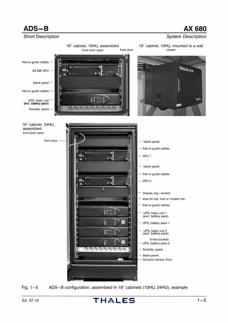
Fig. 1−5 ADS−B configuration, assembled in 19" cabinets (10HU, 24HU), example
AX 680System Description Short Description
ADS−B
1−6 Ed. 07.10
AX 680ADS−BShort Description System Description
1−1Ed. 07.10
1.3 TECHNICAL CHARACTERISTICS
1.3.1 Dimensions and Weight
Ground Station equipment:− AX 680 SPU (HxWxD); weight 19", 2HU; 87 x 482* x 250 mm; approx. 7.1 kg
Configured system versions (optional):
− Small indoor cabinet; HxWxD; weight 19", 10HU; 600 x 600 x 600 mm; approx. 90 kgAX 680 SPU, HxWxD; weight (1x) 19", 2HU; 87 x 482* x 250 mm; approx. 7.1 kgUPS, RT1000, HxWxD; weight (1x) 19", 2HU; 87 x 440** x 400 mm; approx. 17.5 kg
− Medium indoor cabinet, HxWxD; weight 19", 24HU; 1200 x 600 x 600 mm; approx. 150 kgAX 680 SPU, HxWxD; weight (2x) 19", 2HU; 87 x 482* x 250 mm; approx. 7.1 kgUPS, RT2000, HxWxD; weight (2x) 19", 2HU; 87 x 440** x 400 mm; approx. 6.6 kgUPS, battery pack, HxWxD; weight (2x) 19", 2HU; 87 x 440** x 400 mm; approx. 20.5 kg
Medium outdoor cabinet option, HxWxD; weight 19", 24HU; 1530 x 730 x 870 mm; approx. 220 kg* inclusive angle brackets ** exclusive angle brackets
1.3.2 Peripheral Equipment
ADS−B RX antenna options:− Omnidirect. Kathrein, 11.5 dBi, H,∅; weight max. 3420 mm, 60 mm; approx. 26 kg max.− Omnidirectional FAN96, 9 dBi, H,∅; weight max. 2700 mm, 60 mm; approx. 24 kg max.− Omnidirectional AAN186, 6 dBi, H,∅; weight max. 1640 mm, 90 mm; approx. 10 kg max.
Antenna Amplifier Unit (AAU), HxWxD; weight 280 x 180 x 105 mm; approx. 4 kg− AAU support and cover, HxWxD; weight 300 x 255 x 220 mm; approx. 5 kg
GPS antenna (option), (HxW); weight (2x) 60 x 100 mm; approx. 0.3 kg
1.3.3 Power Supply
AX 680 SPU:AC voltage input (AC/DC converter) nom. 115/240 VAC (90 to 264 VAC), 47/63 Hz,
single phasePower consumption AC typ. 100 VA, max. 250 VADC voltage input (DC/DC option) nom. 24 VDC (18 to 36 VDC)Power consumption DC typ. 85 VA, max. 200 VA
UPS types (option) RT1000 or RT2000 with 1 battery packAC voltage input (rated) 230 VAC (186 to 288 VAC), 50 Hz, single phasemax. Current input 3.8 A (RT1000) or 7.8 A (RT2000)AC voltage output 220 VAC (std.), 230/240 VAC (configurable) / 50 Hzeffective Power rating approx. 700 W (RT1000) or 1400 W (RT2000)Batteries (internal or battery pack) 3x 12 V, 7.2 Ah (RT1000), 6x 12 V, 7.2 Ah (RT2000)Typical battery time (battery mode) in [min] standard (intern. battery): 17/6 (50 % / 100 % load)Typical battery time (battery mode) in [min] 1 battery pack: 18/6 (50 % / 100 % load)
Ground Station 19" cabinets (no device assembled):− AC voltage input 100 to 240 VAC, 50/60 Hz, single phase
Connecting power indoor cabinet approx. 490 VA (heating and ventilation)Connecting power outdoor cabinet nom. 590 W (a/c), max. 1000 W (heating)
1.3.4 Environmental Conditions
Ambient temperatureOperation indoor (SPU, UPS) +10 to +40 °COperation outdoor equipment (antennas) −40 to +70 °CTransport / Storage (UPS) −55 to +70 °C / UPS: −25 to +55 °C
AX 680System Description
ADS−BShort Description
1−2 Ed. 07.10
Relative humidityindoor max. 90 %, non condensingoutdoor max. 95 % (−10...39 °C); max. 50 % (−40...70 °C)non operation and transport up to 100 % with condensation
Max. wind velocity optional antennasAntenna Kathrein (11.5 dBi) max. 130 km/hAntenna FAN96 (9 dBi) max. 150 km/hAntenna AAN186 (6 dBi) max. 180 km/h
1.3.5 System Data Ground Station AX 680
ADS−B System basic Ground station built by 1 SPU, coupled to ADS−BLAN, UPS option
ADS−B System option Ground station with redundant equipment, builtby 2 SPU, coupled to ADS−B LAN, UPS option
Receiving signals 1090 ES ADS−B, GPS L1−band 1575.42 MHzCoverage range (within a line of sight) up to 250 NM at flight level > 300, omnidirectionalCapacity (GS) > 250 targets
Communication interface UP/IP, SNMP on UDP/IP, SSH, SCP on TCP/IPReport generation ASTERIX CAT 21 reports (ADS−B),
ASTERIX CAT 23 (status) and Thales Raw Data
1.3.6 Interfaces
AX 680 SPU− RF input receive interface (RX signal) SMA, female− RF input receive interface (GPS signal) SMA, female (with PTM option)− Test Transmitter interface (RF signal) SMA, female− Data interface connector: */** Network RJ45, 8/8, Ethernet 10/100Base−T (rear, NET1, 2)
Auxiliary RJ45, 8/8, Ethernet 10/100Base−T (front, ETH2)Mainten. RJ45, 8/8, Ethernet 10/100Base−T (front, ETH1)Program. Serial, V.24, MicroSubD, 9pin, female (front)
− BITE (GS1 − GS2 status exchange) */** RJ12, 6/6− I/O Status Interface (e.g. ext. equipment) */** SubD, 15pin, male (three−row)− TX control digital (AN1030/1090)*/**not used SubD, 15pin, female (three−row)− TX Control (1090) */** not applicable SubD, 25pin, female (SPU rear)− TX Control (UAT) */** not applicable SubD, 25pin, female (SPU rear)
UPS (optional via SNMP board CS121) */**Data interface connector RJ45, 8/8, Ethernet 10/100Base−T (COM1)Data interface connector (sensors etc.) Mini Din, 8pin (COM2)Auxiliary signalling contacts RJ11, 6/6 (AUX), 4 configurable Input/Output
* according IEC60950 ** SELV−circuit (Safety Extra Low Voltage)
1.3.7 Conformity and Licensing Approval
The AX 680 ground station SPU is compliant to ICAO Annex 10 and to current European Regulationsfor human health (low voltage directive) and electromagnetic compatibility (EMC). It complies withthe requirements of EC Guideline 89/336/EEC in its implementation. It also fulfills the requirementsof the following EMC Guidelines:
− Emission Test: EN 55022 (1998); EN 61000−3−2 (1995); EN 61000−3−3 (1995) − Immunity Tests: EN 55024 (1998); (EN 61000−4−2 (1995); EN 61000−4−11 (1994))
AX 680Short Description Subsystem Description
ADS−B
2−1Ed. 07.10
CHAPTER 2SYSTEM AND SUBSYSTEM DESCRIPTION
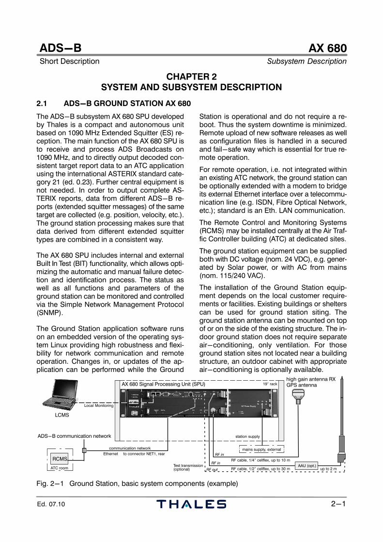
2.1 ADS−B GROUND STATION AX 680
The ADS−B subsystem AX 680 SPU developedby Thales is a compact and autonomous unitbased on 1090 MHz Extended Squitter (ES) re-ception. The main function of the AX 680 SPU isto receive and process ADS Broadcasts on1090 MHz, and to directly output decoded con-sistent target report data to an ATC applicationusing the international ASTERIX standard cate-gory 21 (ed. 0.23). Further central equipment isnot needed. In order to output complete AS-TERIX reports, data from different ADS−B re-ports (extended squitter messages) of the sametarget are collected (e.g. position, velocity, etc.).The ground station processing makes sure thatdata derived from different extended squittertypes are combined in a consistent way.
The AX 680 SPU includes internal and externalBuilt In Test (BIT) functionality, which allows opti-mizing the automatic and manual failure detec-tion and identification process. The status aswell as all functions and parameters of theground station can be monitored and controlledvia the Simple Network Management Protocol(SNMP).
The Ground Station application software runson an embedded version of the operating sys-tem Linux providing high robustness and flexi-bility for network communication and remoteoperation. Changes in, or updates of the ap-plication can be performed while the Ground
Station is operational and do not require a re-boot. Thus the system downtime is minimized.Remote upload of new software releases as wellas configuration files is handled in a securedand fail−safe way which is essential for true re-mote operation.
For remote operation, i.e. not integrated withinan existing ATC network, the ground station canbe optionally extended with a modem to bridgeits external Ethernet interface over a telecommu-nication line (e.g. ISDN, Fibre Optical Network,etc.); standard is an Eth. LAN communication.
The Remote Control and Monitoring Systems(RCMS) may be installed centrally at the Air Traf-fic Controller building (ATC) at dedicated sites.
The ground station equipment can be suppliedboth with DC voltage (nom. 24 VDC), e.g. gener-ated by Solar power, or with AC from mains(nom. 115/240 VAC).
The installation of the Ground Station equip-ment depends on the local customer require-ments or facilities. Existing buildings or shelterscan be used for ground station siting. Theground station antenna can be mounted on topof or on the side of the existing structure. The in-door ground station does not require separateair−conditioning, only ventilation. For thoseground station sites not located near a buildingstructure, an outdoor cabinet with appropriateair−conditioning is optionally available.
high gain antenna RX
LCMS
Local Monitoring
communication network
ADS−B communication network
19" rack
to connector NET1, rear
RF in
Ethernet
station supply
RF cable, 1/2" cellflex, up to 30 m
mains supply, external
Test transmission
RF in
RF out
GPS antenna
AAU (opt.)
RCMS
ATC room
RF cable, 1/4" cellflex, up to 10 m
up to 2 m
AX 680 Signal Processing Unit (SPU)
(optional)
Fig. 2−1 Ground Station, basic system components (example)
AX 680Subsystem Description Short Description
ADS−B
2−2 Ed. 07.10
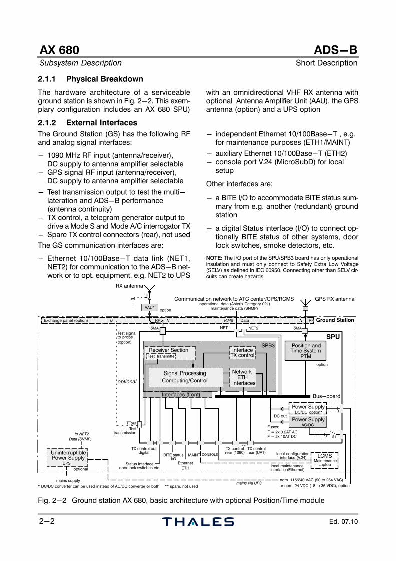
2.1.1 Physical Breakdown
The hardware architecture of a serviceableground station is shown in Fig. 2−2. This exem-plary configuration includes an AX 680 SPU)
with an omnidirectional VHF RX antenna withoptional Antenna Amplifier Unit (AAU), the GPSantenna (option) and a UPS option
2.1.2 External Interfaces
The Ground Station (GS) has the following RFand analog signal interfaces:
− 1090 MHz RF input (antenna/receiver), DC supply to antenna amplifier selectable
− GPS signal RF input (antenna/receiver), DC supply to antenna amplifier selectable
− Test transmission output to test the multi−lateration and ADS−B performance (antenna continuity)
− TX control, a telegram generator output todrive a Mode S and Mode A/C interrogator TX
− Spare TX control connectors (rear), not used
The GS communication interfaces are:
− Ethernet 10/100Base−T data link (NET1,NET2) for communication to the ADS−B net-work or to opt. equipment, e.g. NET2 to UPS
− independent Ethernet 10/100Base−T , e.g. for maintenance purposes (ETH1/MAINT)
− auxiliary Ethernet 10/100Base−T (ETH2)− console port V.24 (MicroSubD) for local
setup
Other interfaces are:
− a BITE I/O to accommodate BITE status sum-mary from e.g. another (redundant) groundstation
− a digital Status interface (I/O) to connect op-tionally BITE status of other systems, doorlock switches, smoke detectors, etc.
NOTE: The I/O port of the SPU/SPB3 board has only operationalinsulation and must only connect to Safety Extra Low Voltage(SELV) as defined in IEC 60950. Connecting other than SELV cir-cuits can create hazards.
Signal Processing
SPB3
Computing/Control
Power Supply
F
AC/DC
S1
nom. 115/240 VAC (90 to 264 VAC)
DC out
Bus−board
SPU
Ethernet
Ground Station
NET1 NET2
door lock switches etc.
local configuration interface (V.24)
operational data (Asterix Category 021)maintenance data (SNMP)
BITE status
MaintenanceLaptop
LCMS
or nom. 24 VDC (18 to 36 VDC), option
F = 2x 3.2AT AC
DC/DC option* F
Fuses:
local maintenance interface (Ethernet)
Communication network to ATC center/CPS/RCMS
* DC/DC converter can be used instead of AC/DC converter or both
RX antenna
Exchange panel (option)
Interfaces
NetworkETH
MAINT
ETH
InterfaceTX control
I/O
TX control TX controlrear (1090) rear (UAT)
GPS RX antenna
Position andTime System
option
DataRF
TX control out
Status Interface
PTM
Interfaces (front)
mains supply
optional
mains via UPS
RF
SMA
RJ45
SMA
Power Supply
** spare, not used
**
UninterruptiblePower Supply
UPS
Data (SNMP)
Testtransmission
TTout
digital
Receiver SectionTest transmitter
Test signal
(option)to probe
F = 2x 10AT DC
NNN
CONSOLE
optional
to NET2
optionAAU*
Fig. 2−2 Ground station AX 680, basic architecture with optional Position/Time module
AX 680Short Description Subsystem Description
ADS−B
2−3Ed. 07.10
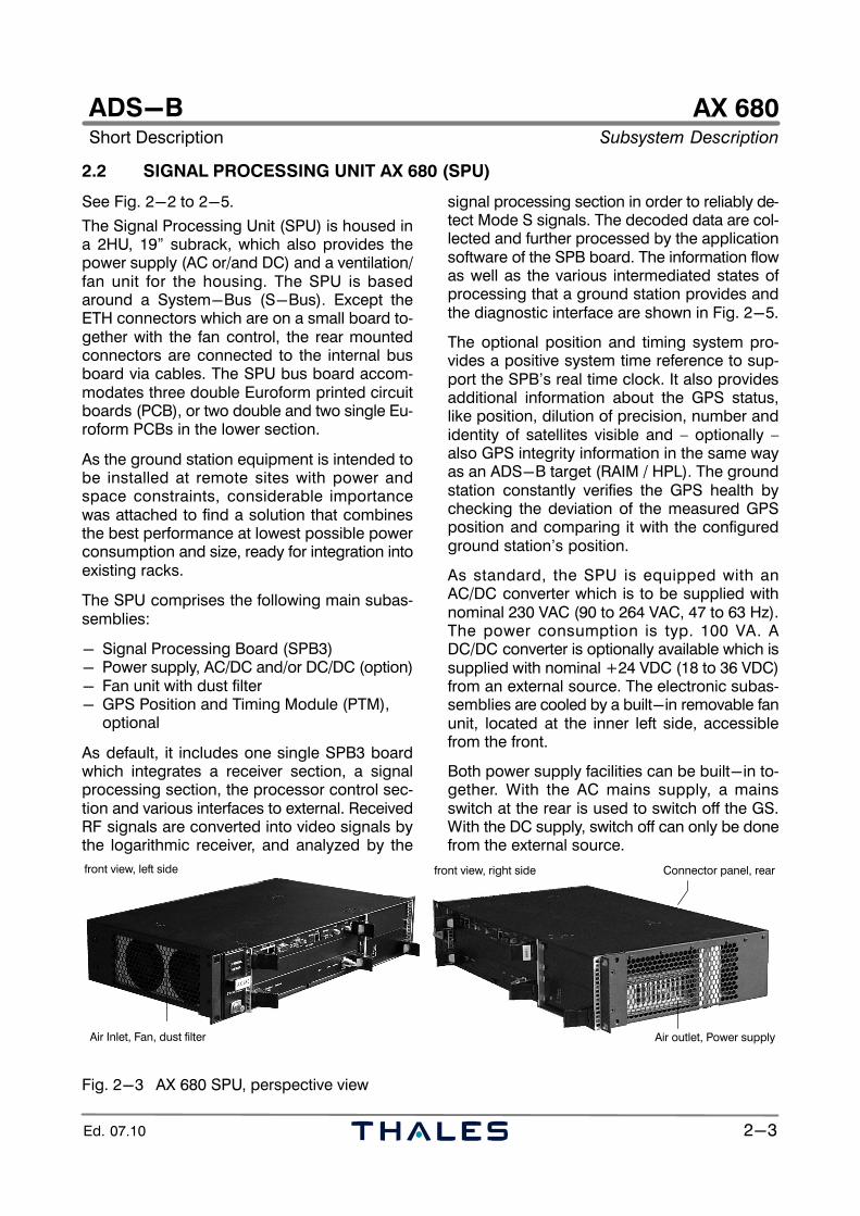
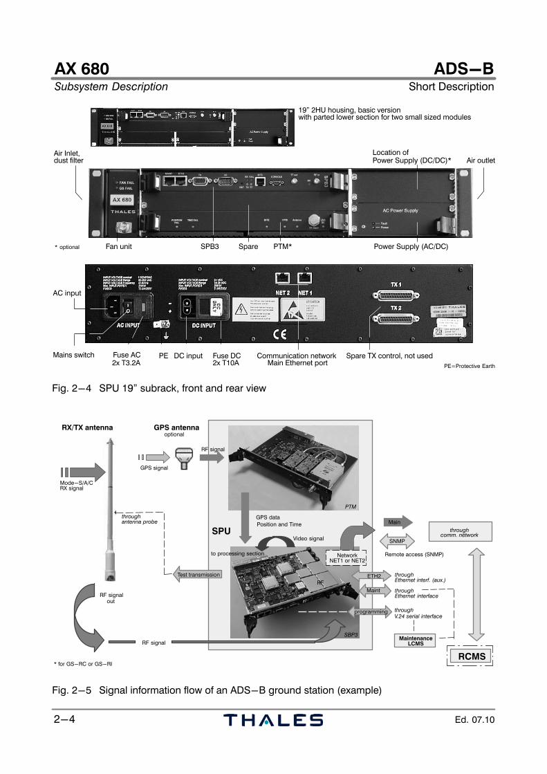
2.2 SIGNAL PROCESSING UNIT AX 680 (SPU)
See Fig. 2−2 to 2−5.
The Signal Processing Unit (SPU) is housed ina 2HU, 19" subrack, which also provides thepower supply (AC or/and DC) and a ventilation/fan unit for the housing. The SPU is basedaround a System−Bus (S−Bus). Except theETH connectors which are on a small board to-gether with the fan control, the rear mountedconnectors are connected to the internal busboard via cables. The SPU bus board accom-modates three double Euroform printed circuitboards (PCB), or two double and two single Eu-roform PCBs in the lower section.
As the ground station equipment is intended tobe installed at remote sites with power andspace constraints, considerable importancewas attached to find a solution that combinesthe best performance at lowest possible powerconsumption and size, ready for integration intoexisting racks.
The SPU comprises the following main subas-semblies:
− Signal Processing Board (SPB3)− Power supply, AC/DC and/or DC/DC (option)− Fan unit with dust filter− GPS Position and Timing Module (PTM),
optional
As default, it includes one single SPB3 boardwhich integrates a receiver section, a signalprocessing section, the processor control sec-tion and various interfaces to external. ReceivedRF signals are converted into video signals bythe logarithmic receiver, and analyzed by the
signal processing section in order to reliably de-tect Mode S signals. The decoded data are col-lected and further processed by the applicationsoftware of the SPB board. The information flowas well as the various intermediated states ofprocessing that a ground station provides andthe diagnostic interface are shown in Fig. 2−5.
The optional position and timing system pro-vides a positive system time reference to sup-port the SPB’s real time clock. It also providesadditional information about the GPS status,like position, dilution of precision, number andidentity of satellites visible and – optionally –also GPS integrity information in the same wayas an ADS−B target (RAIM / HPL). The groundstation constantly verifies the GPS health bychecking the deviation of the measured GPSposition and comparing it with the configuredground station’s position.
As standard, the SPU is equipped with anAC/DC converter which is to be supplied withnominal 230 VAC (90 to 264 VAC, 47 to 63 Hz).The power consumption is typ. 100 VA. ADC/DC converter is optionally available which issupplied with nominal +24 VDC (18 to 36 VDC)from an external source. The electronic subas-semblies are cooled by a built−in removable fanunit, located at the inner left side, accessiblefrom the front.
Both power supply facilities can be built−in to-gether. With the AC mains supply, a mainsswitch at the rear is used to switch off the GS.With the DC supply, switch off can only be donefrom the external source.
Air Inlet, Fan, dust filter
front view, left side
Air outlet, Power supply
front view, right side Connector panel, rear
Fig. 2−3 AX 680 SPU, perspective view
AX 680Subsystem Description Short Description
ADS−B
2−4 Ed. 07.10
Power Supply (DC/DC)*Air Inlet,
SPB3Fan unit PTM*
Air outlet
* optional
19" 2HU housing, basic version
Power Supply (AC/DC)
with parted lower section for two small sized modules
Spare
dust filterLocation of
DC inputFuse AC
AC input
Fuse DCMains switch PE
PE=Protective Earth
Communication network Spare TX control, not used2x T3.2A 2x T10A Main Ethernet port
Fig. 2−4 SPU 19" subrack, front and rear view
GPS signal
RF signal
GPS data
Video signalSPU
Remote access (SNMP)
RF signal
SNMP
Main
GPS antenna
throughEthernet interf. (aux.)
throughV.24 serial interface
throughantenna probe
Mode−S/A/C
optionaloptional
RF signalout
RCMS
throughcomm. network
RX/TX antenna
Position and Time
Test transmission
MaintenanceLCMS
RF
to processing section NetworkNET1 or NET2
* for GS−RC or GS−RI
ETH2
throughEthernet interface
programming
RX signal
Maint
PTM
SBP3
Fig. 2−5 Signal information flow of an ADS−B ground station (example)
AX 680Short Description Subsystem Description
ADS−B
2−5Ed. 07.10
2.3 OPTIONAL EQUIPMENT
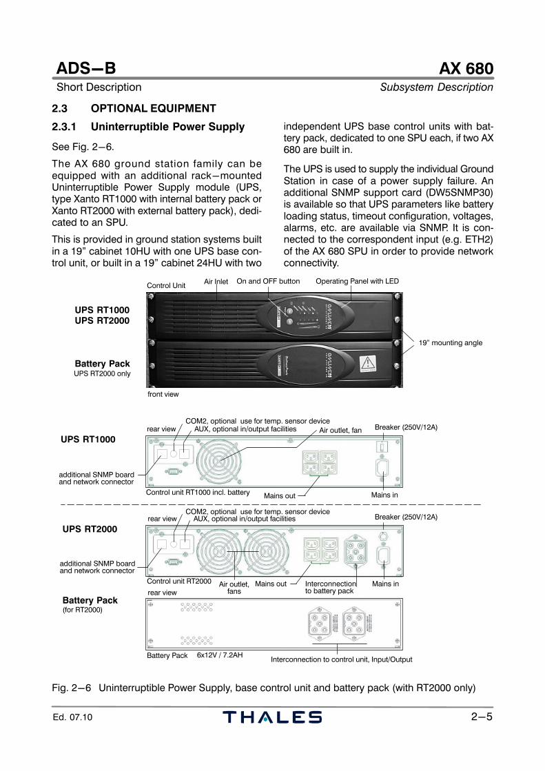
2.3.1 Uninterruptible Power Supply
See Fig. 2−6.
The AX 680 ground station family can beequipped with an additional rack−mountedUninterruptible Power Supply module (UPS,type Xanto RT1000 with internal battery pack orXanto RT2000 with external battery pack), dedi-cated to an SPU.
This is provided in ground station systems builtin a 19" cabinet 10HU with one UPS base con-trol unit, or built in a 19" cabinet 24HU with two
independent UPS base control units with bat-tery pack, dedicated to one SPU each, if two AX680 are built in.
The UPS is used to supply the individual GroundStation in case of a power supply failure. Anadditional SNMP support card (DW5SNMP30)is available so that UPS parameters like batteryloading status, timeout configuration, voltages,alarms, etc. are available via SNMP. It is con-nected to the correspondent input (e.g. ETH2)of the AX 680 SPU in order to provide networkconnectivity.
Operating Panel with LEDOn and OFF button
UPS RT1000UPS RT2000
Battery Pack
Control Unit
UPS RT2000 only
front view
19" mounting angle
Air Inlet
rear view
Mains out
Mains in
Interconnectionto battery pack
rear view
and network connectoradditional SNMP board
Battery Pack 6x12V / 7.2AH
Mains out
Mains in
and network connectoradditional SNMP board
rear view
UPS RT1000
UPS RT2000
Battery Pack
Control unit RT2000
Control unit RT1000 incl. battery
(for RT2000)
AUX, optional in/output facilities
COM2, optional use for temp. sensor deviceAUX, optional in/output facilities
COM2, optional use for temp. sensor deviceBreaker (250V/12A)
Breaker (250V/12A)
Interconnection to control unit, Input/Output
Air outlet, fan
Air outlet,fans
Fig. 2−6 Uninterruptible Power Supply, base control unit and battery pack (with RT2000 only)
AX 680Subsystem Description Short Description
ADS−B
2−6 Ed. 07.10
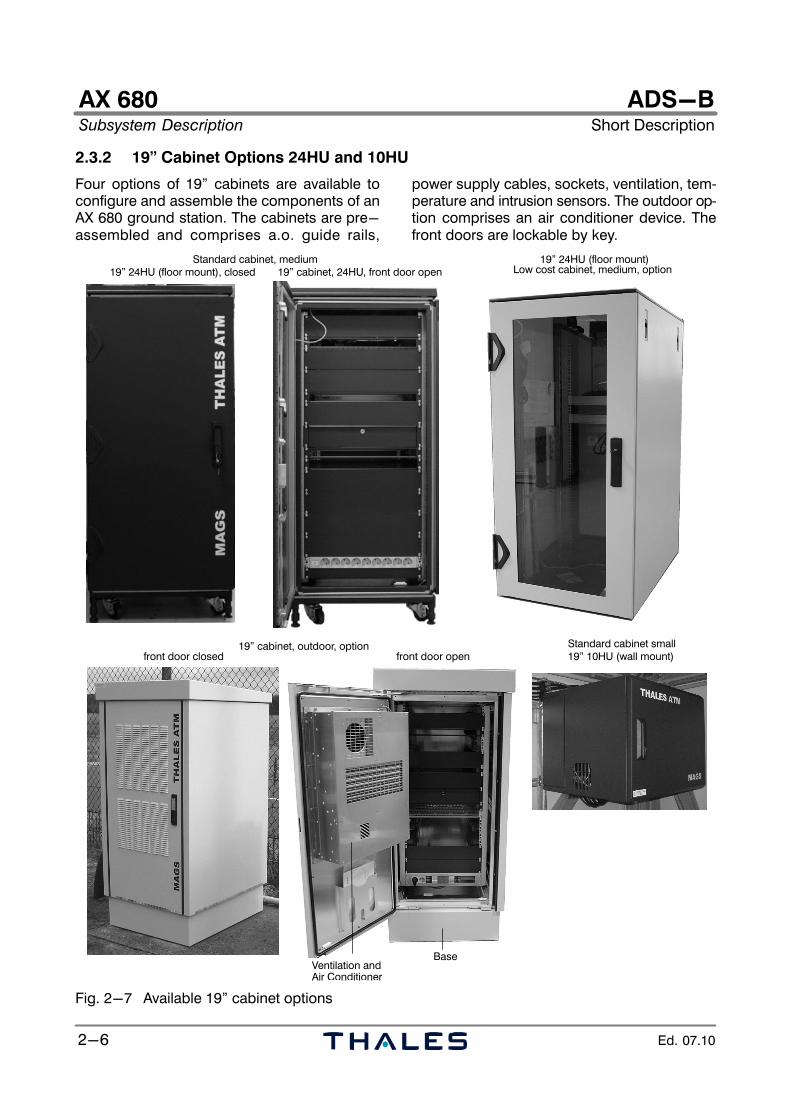
2.3.2 19" Cabinet Options 24HU and 10HU
Four options of 19" cabinets are available toconfigure and assemble the components of anAX 680 ground station. The cabinets are pre−assembled and comprises a.o. guide rails,
power supply cables, sockets, ventilation, tem-perature and intrusion sensors. The outdoor op-tion comprises an air conditioner device. Thefront doors are lockable by key.
Standard cabinet, medium19" 24HU (floor mount), closed
Standard cabinet small
Low cost cabinet, medium, option19" 24HU (floor mount)
19" cabinet, 24HU, front door open
19" 10HU (wall mount)19" cabinet, outdoor, option
Ventilation and
front door openfront door closed
Air Conditioner
Base
Fig. 2−7 Available 19" cabinet options
AX 680Short Description Subsystem Description
ADS−B
2−7Ed. 07.10
2.4 PERIPHERAL EQUIPMENT
2.4.1 Omnidirectional Antenna and Antenna Amplifier Unit (AAU)
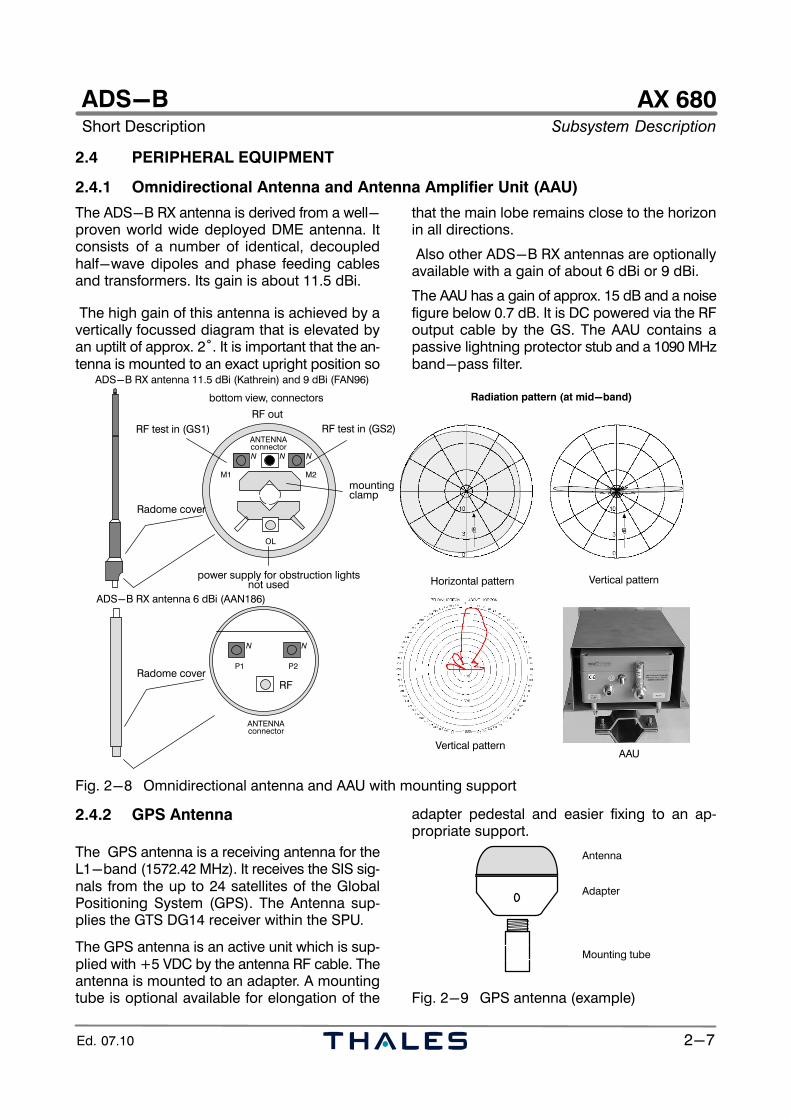
The ADS−B RX antenna is derived from a well−proven world wide deployed DME antenna. Itconsists of a number of identical, decoupledhalf−wave dipoles and phase feeding cablesand transformers. Its gain is about 11.5 dBi.
The high gain of this antenna is achieved by avertically focussed diagram that is elevated byan uptilt of approx. 2°. It is important that the an-tenna is mounted to an exact upright position so
that the main lobe remains close to the horizonin all directions.
Also other ADS−B RX antennas are optionallyavailable with a gain of about 6 dBi or 9 dBi.
The AAU has a gain of approx. 15 dB and a noisefigure below 0.7 dB. It is DC powered via the RFoutput cable by the GS. The AAU contains apassive lightning protector stub and a 1090 MHzband−pass filter.
bottom view, connectors
RF out
RF test in (GS1) RF test in (GS2)
power supply for obstruction lightsnot used
mountingclamp
Radome cover
OL
M1 M2
ANTENNAconnectorN N N
RF
P1 P2
ANTENNAconnector
N N
ADS−B RX antenna 6 dBi (AAN186)
Radome cover
ADS−B RX antenna 11.5 dBi (Kathrein) and 9 dBi (FAN96)
Vertical patternHorizontal pattern
Vertical pattern
Radiation pattern (at mid−band)
AAU
Fig. 2−8 Omnidirectional antenna and AAU with mounting support
2.4.2 GPS Antenna
The GPS antenna is a receiving antenna for theL1−band (1572.42 MHz). It receives the SIS sig-nals from the up to 24 satellites of the GlobalPositioning System (GPS). The Antenna sup-plies the GTS DG14 receiver within the SPU.
The GPS antenna is an active unit which is sup-plied with +5 VDC by the antenna RF cable. Theantenna is mounted to an adapter. A mountingtube is optional available for elongation of the
adapter pedestal and easier fixing to an ap-propriate support.
Antenna
Adapter
Mounting tube
Fig. 2−9 GPS antenna (example)
AX 680Subsystem Description Short Description
ADS−B
2−8 Ed. 07.10
AX 680Short Description Subsystem Description
ADS−B
2−9Ed. 07.10
2.5 REMOTE/LOCAL CONTROL AND MONITORING SYSTEM (RCMS/LCMS)
See Figs. 2−10 to .
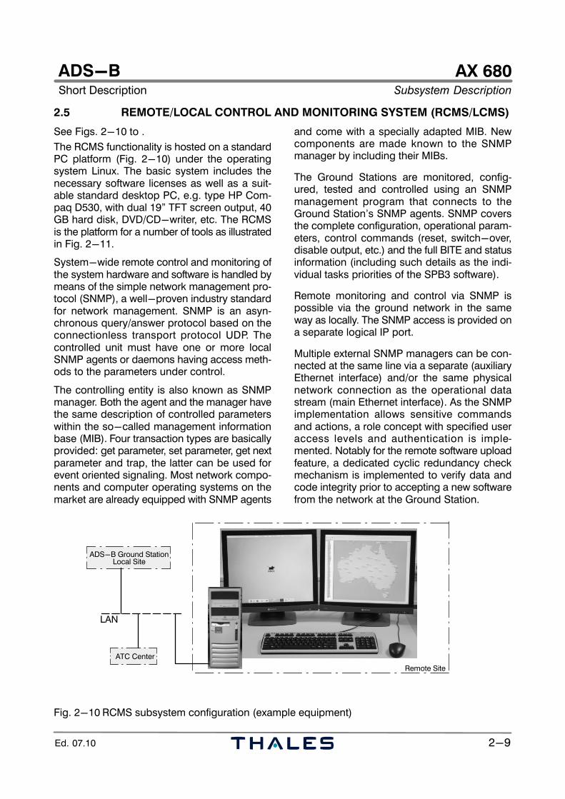
The RCMS functionality is hosted on a standardPC platform (Fig. 2−10) under the operatingsystem Linux. The basic system includes thenecessary software licenses as well as a suit-able standard desktop PC, e.g. type HP Com-paq D530, with dual 19" TFT screen output, 40GB hard disk, DVD/CD−writer, etc. The RCMSis the platform for a number of tools as illustratedin Fig. 2−11.
System−wide remote control and monitoring ofthe system hardware and software is handled bymeans of the simple network management pro-tocol (SNMP), a well−proven industry standardfor network management. SNMP is an asyn-chronous query/answer protocol based on theconnectionless transport protocol UDP. Thecontrolled unit must have one or more localSNMP agents or daemons having access meth-ods to the parameters under control.
The controlling entity is also known as SNMPmanager. Both the agent and the manager havethe same description of controlled parameterswithin the so−called management informationbase (MIB). Four transaction types are basicallyprovided: get parameter, set parameter, get nextparameter and trap, the latter can be used forevent oriented signaling. Most network compo-nents and computer operating systems on themarket are already equipped with SNMP agents
and come with a specially adapted MIB. Newcomponents are made known to the SNMPmanager by including their MIBs.
The Ground Stations are monitored, config-ured, tested and controlled using an SNMPmanagement program that connects to theGround Station’s SNMP agents. SNMP coversthe complete configuration, operational param-eters, control commands (reset, switch−over,disable output, etc.) and the full BITE and statusinformation (including such details as the indi-vidual tasks priorities of the SPB3 software).
Remote monitoring and control via SNMP ispossible via the ground network in the sameway as locally. The SNMP access is provided ona separate logical IP port.
Multiple external SNMP managers can be con-nected at the same line via a separate (auxiliaryEthernet interface) and/or the same physicalnetwork connection as the operational datastream (main Ethernet interface). As the SNMPimplementation allows sensitive commandsand actions, a role concept with specified useraccess levels and authentication is imple-mented. Notably for the remote software uploadfeature, a dedicated cyclic redundancy checkmechanism is implemented to verify data andcode integrity prior to accepting a new softwarefrom the network at the Ground Station.
LAN
ADS−B Ground Station
Remote Site
ATC Center
Local Site
Fig. 2−10 RCMS subsystem configuration (example equipment)
AX 680Subsystem Description Short Description
ADS−B
2−10 Ed. 07.10
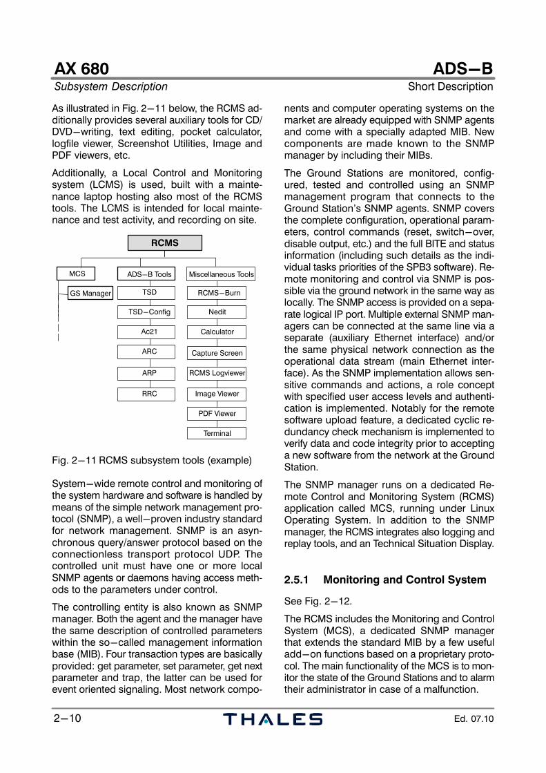
As illustrated in Fig. 2−11 below, the RCMS ad-ditionally provides several auxiliary tools for CD/DVD−writing, text editing, pocket calculator,logfile viewer, Screenshot Utilities, Image andPDF viewers, etc.
Additionally, a Local Control and Monitoringsystem (LCMS) is used, built with a mainte-nance laptop hosting also most of the RCMStools. The LCMS is intended for local mainte-nance and test activity, and recording on site.
MCS ADSB
GS Manager
ADS−B Tools Miscellaneous Tools
RCMS−Burn
Nedit
Calculator
RCMS Logviewer
Image Viewer
PDF Viewer
Terminal
RRC
ARC
ARP
TSD
Ac21
RCMS
Capture Screen
TSD−Config
Fig. 2−11 RCMS subsystem tools (example)
System−wide remote control and monitoring ofthe system hardware and software is handled bymeans of the simple network management pro-tocol (SNMP), a well−proven industry standardfor network management. SNMP is an asyn-chronous query/answer protocol based on theconnectionless transport protocol UDP. Thecontrolled unit must have one or more localSNMP agents or daemons having access meth-ods to the parameters under control.
The controlling entity is also known as SNMPmanager. Both the agent and the manager havethe same description of controlled parameterswithin the so−called management informationbase (MIB). Four transaction types are basicallyprovided: get parameter, set parameter, get nextparameter and trap, the latter can be used forevent oriented signaling. Most network compo-
nents and computer operating systems on themarket are already equipped with SNMP agentsand come with a specially adapted MIB. Newcomponents are made known to the SNMPmanager by including their MIBs.
The Ground Stations are monitored, config-ured, tested and controlled using an SNMPmanagement program that connects to theGround Station’s SNMP agents. SNMP coversthe complete configuration, operational param-eters, control commands (reset, switch−over,disable output, etc.) and the full BITE and statusinformation (including such details as the indi-vidual tasks priorities of the SPB3 software). Re-mote monitoring and control via SNMP is pos-sible via the ground network in the same way aslocally. The SNMP access is provided on a sepa-rate logical IP port. Multiple external SNMP man-agers can be connected at the same line via aseparate (auxiliary Ethernet interface) and/orthe same physical network connection as theoperational data stream (main Ethernet inter-face). As the SNMP implementation allows sen-sitive commands and actions, a role conceptwith specified user access levels and authenti-cation is implemented. Notably for the remotesoftware upload feature, a dedicated cyclic re-dundancy check mechanism is implemented toverify data and code integrity prior to acceptinga new software from the network at the GroundStation.
The SNMP manager runs on a dedicated Re-mote Control and Monitoring System (RCMS)application called MCS, running under LinuxOperating System. In addition to the SNMPmanager, the RCMS integrates also logging andreplay tools, and an Technical Situation Display.
2.5.1 Monitoring and Control System
See Fig. 2−12.
The RCMS includes the Monitoring and ControlSystem (MCS), a dedicated SNMP managerthat extends the standard MIB by a few usefuladd−on functions based on a proprietary proto-col. The main functionality of the MCS is to mon-itor the state of the Ground Stations and to alarmtheir administrator in case of a malfunction.
AX 680Short Description Subsystem Description
ADS−B
2−11Ed. 07.10
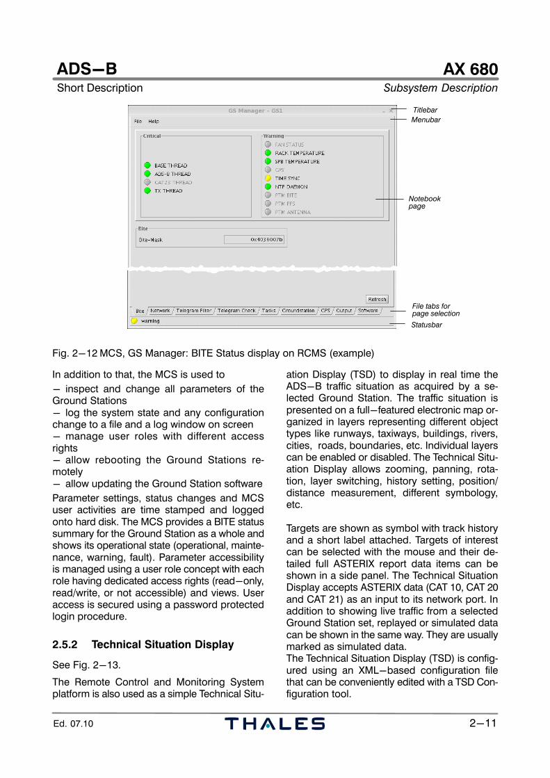
Titlebar
Menubar
Statusbar
Notebookpage
File tabs forpage selection
Fig. 2−12 MCS, GS Manager: BITE Status display on RCMS (example)
In addition to that, the MCS is used to
− inspect and change all parameters of theGround Stations− log the system state and any configurationchange to a file and a log window on screen− manage user roles with different accessrights− allow rebooting the Ground Stations re-motely− allow updating the Ground Station software
Parameter settings, status changes and MCSuser activities are time stamped and loggedonto hard disk. The MCS provides a BITE statussummary for the Ground Station as a whole andshows its operational state (operational, mainte-nance, warning, fault). Parameter accessibilityis managed using a user role concept with eachrole having dedicated access rights (read−only,read/write, or not accessible) and views. Useraccess is secured using a password protectedlogin procedure.
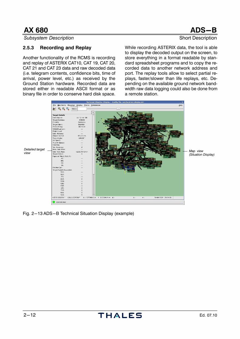
2.5.2 Technical Situation Display
See Fig. 2−13.
The Remote Control and Monitoring Systemplatform is also used as a simple Technical Situ-
ation Display (TSD) to display in real time theADS−B traffic situation as acquired by a se-lected Ground Station. The traffic situation ispresented on a full−featured electronic map or-ganized in layers representing different objecttypes like runways, taxiways, buildings, rivers,cities, roads, boundaries, etc. Individual layerscan be enabled or disabled. The Technical Situ-ation Display allows zooming, panning, rota-tion, layer switching, history setting, position/distance measurement, different symbology,etc.
Targets are shown as symbol with track historyand a short label attached. Targets of interestcan be selected with the mouse and their de-tailed full ASTERIX report data items can beshown in a side panel. The Technical SituationDisplay accepts ASTERIX data (CAT 10, CAT 20and CAT 21) as an input to its network port. Inaddition to showing live traffic from a selectedGround Station set, replayed or simulated datacan be shown in the same way. They are usuallymarked as simulated data.The Technical Situation Display (TSD) is config-ured using an XML−based configuration filethat can be conveniently edited with a TSD Con-figuration tool.
AX 680Subsystem Description Short Description
ADS−B
2−12 Ed. 07.10
2.5.3 Recording and Replay
Another functionality of the RCMS is recordingand replay of ASTERIX CAT10, CAT 19, CAT 20,CAT 21 and CAT 23 data and raw decoded data(i.e. telegram contents, confidence bits, time ofarrival, power level, etc.) as received by theGround Station hardware. Recorded data arestored either in readable ASCII format or asbinary file in order to conserve hard disk space.
While recording ASTERIX data, the tool is ableto display the decoded output on the screen, tostore everything in a format readable by stan-dard spreadsheet programs and to copy the re-corded data to another network address andport. The replay tools allow to select partial re-plays, faster/slower than life replays, etc. De-pending on the available ground network band-width raw data logging could also be done froma remote station.
Detailed targetview
Map view(Situation Display)
Fig. 2−13 ADS−B Technical Situation Display (example)

Points of Contact:
THALES Air Systems GmbH P.O. Box 1140 · D−70807 Korntal−Münchingen Germany
Telephone: +49 711 86032−151 · Telefax: +49 711 86032 804e−mail: [email protected]
THALES ATM Inc. 23501 West 84th Street · Shawnee, Kansas 66227 USA
Telephone: +1 913 42226−00 · Telefax: +1 913 42229 62e−mail: [email protected]
THALES Italia S.p.A.Via E. Mattei 1 · 20064 Gorgonzola (MI) Italy
Telephone: +39 02 9509−51 · Telefax: +39 02 9509 5321e−mail: [email protected]
AIR SYSTEMS DIVISION