Embed Size (px)
Citation preview
Air Stripping Designs and Reactive Water PurificationProcesses for the Lunar Surface
Peter J. Boul'ERC Inc., Engineering and Science Contract Group, 2224 Bay Area Blvd., Houston, Tx. 77058
Kevin E. LangezJacobs Engineering, Engineering and Science Contract Group, 2224 Bay Area Blvd., Houston, Tx. 77058
Bruce Conger'Hamilton Sundstrand, Engineering and Science Contract Group, 2224 Bay Area Blvd., Houston, Tx. 77058
and
Molly Anderson NASA-Johnson Space Center, Houston, Tx. 77058
Air stripping designs are considered to reduce the presence of volatile organic compounds in the purified water.Components of the wastewater streams are ranked by Henry's Law Constant and the suitability of air stripping in thepurification of wastewater in teens of component removal is evaluated. Distillation processes are modeled intandem with air stripping to demonstrate the potential effectiveness and utility of these methods in recyclingwastewater on the Moon. Scaling factors for distillation and air stripping columns are presented to account for thedifference in the lunar gravitation environment. Commercially available distillation and air stripping units which areconsidered suitable for Exploration Life Support are presented. The advantages to the various designs aresummarized with respect to water purity levels, power consumption, and processing rates.
An evaluation of reactive distillation and air stripping is presented with regards to the reduction of volatile organiccompounds in the contaminated water and air. Among the methods presented, an architecture is presented for theevaluation of the simultaneous oxidation of organics in air and water. These and other designs are presented in lightof potential improvements in power consumptions and air and water purities for architectures which includecatalytic activity integrated into the water processor. In particular, catalytic oxidation of organics may be useful as atool to remove contaminants that more traditional distillation and/or air stripping colun ns may not remove. Areview of the current leading edge at the conniercial level and at the research frontier in catalytically activematerials is presented. Themes and directions from the engineering developments in catalyst design are presentedconceptually in light of developments in the nanoscale chemistry of a variety of catalyst materials.
Nomenclature°C = Degrees Celsiuscm = CentimeterCOz = Carbon DioxideEPA = Environmental Protection Agency
' Staff Scientist, ERC Inc. ; Engineering and Science Contract Group, 2224 Bay Area Blvd.. Houston, Tx. 77058 andnot an AIAA Member.'` Project Engineer, Engineering and Science Contract Group, 2224 Bay Area Blvd.. Houston, Tx. 77058, and AIAAMember Grade for second author.3 Project Manager, Engineering and Science Contract Group, 2224 Bay Area Blvd.. Houston, Tx. 77058, and AIAA.4 ELS SIMA Element Lead, NASA-Johnson Space Center, Houston, Tx. 77058
American Institute of Aeronautics and Astronautics
https://ntrs.nasa.gov/search.jsp?R=20100016329 2018-02-01T03:48:52+00:00Z
:allect
-ipper
water sprayed overpacking material
packing material
air rises through packing material
water trickles to bottom
— air blower
clean water
Ft = Footg = gramHCA = Humidity Condensate Model AHETP = Height Equivalent Theoretical PlateISS = International Space StationJSC = Johnson Space CenterkW = KilowattMCL = Maximum Concentration Levelyg/L = Micro grams per LitermL = MilliliterMM = Millimeterm/S = Meters per secondNaOH = Sodium HvdroxideNASA = National Aeronautics and Space Administration02 = OxygenPa = PascalRD = Reactive DistillationVOC = Volatile Organic CompoundW = Watt
I. Introduction
any designs for water purification feature disposable parts or processes that produce waste. For example,carbon dioxide (CO2) removal with lithium hydroxide is an effective, but not readily regenerable process [1].
The reaction product of CO2 and lithium hydroxide is lithium carbonate, which makes this process non-regenerable.Biocatalytic processes are also less than favorable due to their high maintenance requirements. Distillation and airstripping are physico -chemicalprocesses, which are robust and well established. This report evaluates the powerconsumptions, component removal feasibility, and scaling factors for the purification of wastewater on the lunarsurface through these processes.
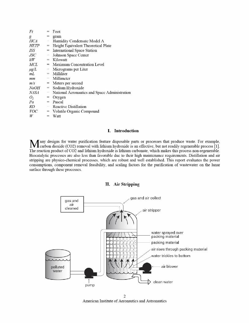
II. Air Stripping
pump
2American Institute of Aeronautics and Astronautics
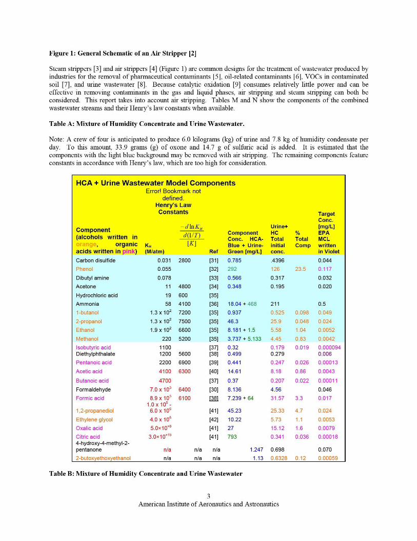
Figure 1: General Schematic of an Air Stripper [2]
Steam strippers [3] and air strippers [4] (Figure 1) are common designs for the treatment of wastewater produced byindustries for the removal of pharmaceutical contannants [5], oil-related contaminants [6], VOCs in contaminatedsoil [7], and urine wastewater [8]. Because catalytic oxidation [9] consumes relatively little power and can beeffective in removing contaminants in the gas and liquid phases, air stripping and steam stripping can both beconsidered. This report takes into account air stripping. Tables M and N show the components of the combinedwastewater streams and their Henry's law constants when available.
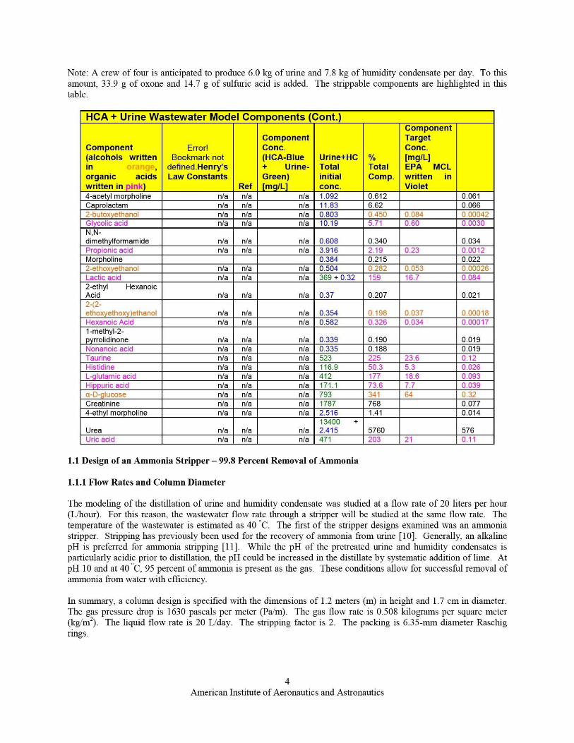
Table A: Mixture of Humidity Concentrate and Urine Wastewater.
Note: A crew of four is anticipated to produce 6.0 kilograms (kg) of urine and 7.8 kg of humidity condensate perday. To this amount, 33.9 grams (g) of oxone and 14.7 g of sulfuric acid is added. It is estimated that thecomponents with the light blue background may be removed with air stripping. The remaining components featureconstants in accordance with Henry's law, which are too high for consideration.
HCA + Urine Wastewater Model ComponentsError! Bookmark not
defined.Henry's LawConstants Target
Conc.-din K„ Urine+ [mg/L]
Componentd(11T) Component HC % EPA
alcohols written in Conc. HCA- Total Total MCL^taYiy^, organic K„ [K] Blue + Urine- initial Comp writtenacids written in pink) (M/atm) Ref Green [mg/L] Conc. in VioletCarbon disulfide 0.031 2800 [31] 0.785 .4396 0.044Phenol 0.055 [32] 292 126 23.5 0.117Dibutyl amine 0.078 [33] 0.566 0.317 0.032Acetone 11 4800 [34] 0.348 0.195 0.020Hydrochloric acid 19 600 [35]Ammonia 58 4100 [36] 18.04+468 211 0.51-butanol 1.3 x 10 2 7200 [35] 0.937 0.525 0.098 0.0492-propanol 1.3 x 10 2 7500 [35] 46.3 25.9 0.048 0.024Ethanol 1.9 x 10 2 6600 [35] 8.181 + 1.5 5.58 1.04 0.0052Methanol 220 5200 [35] 3.737 + 5.133 4.45 0.83 0.0042Isobutyric acid 1100 [37] 0.32 0.179 0.019 0.000094Diethylphthalate 1200 5600 [38] 0.499 0.279 0.006Pentanoic acid 2200 6900 [39] 0.441 0.247 0.026 0.00013Acetic acid 4100 6300 [40] 14.61 8.18 0.86 0.0043Butanoic acid 4700 [37] 0.37 0.207 0.022 0.00011Formaldehyde 7.0 x 10 3 6400 [30] 8.136 4.56 0.046Formic acid 8.9 x 10 3 6100 ]381 7.239+64 31.57 3.3 0.017
1.0 x 10 5 -1,2-propanediol 6.0 x 10 6 [41] 45.23 25.33 4.7 0.024Ethylene glycol 4.0 x 10⁶ [42] 10.22 5.73 1.1 0.0053Oxalic acid 5.0x10+8 [41] 27 15.12 1.6 0.0079Citric acid 3.0x10"8 [41] 793 0.341 0.036 0.000184-hyd roxy-4-m ethyl -2-pentanone n/a n/a n/a 1.247 0.698 0.0702-butoxyethoxyethanol n/a n/a n/a 1.13 0.6328 0.12 0.00059
Table B: Mixture of Humidity Concentrate and Urine Wastewater
3American Institute of Aeronautics and Astronautics
Note: A crew of four is anticipated to produce 6.0 kg of urine and 7.8 kg of humidity condensate per day. To thisamount, 33.9 g of oxone and 14.7 g of sulfuric acid is added. The strippable components are highlighted in thistable.
HCA+ Urine Wastewater Model Components (Cont.)
Component(alcohols writtenin oranae,organic acidswritten in pink)
Error!Bookmark not
defined-Henry'sLaw Constants
Ref
ComponentConc.(HCA-Blue+ Urine-Green)[mg/L]
Urine+HCTotalinitialconc.
%TotalComp.
ComponentTargetConc.[mg/L]EPA MCLwritten inViolet
4-acetyl morpholine n/a n/a n/a 1.092 0.612 0.061Ca rolactam n/a n/a n/a 11.83 6.62 0.066.'-butox ethanol n/a n/a n/a 0.803 0.450 0.084 0.00042Glycolic acid n/a n/a n/a 10.19 5.71 0.60 0.0030N,N-
dimethylformamide n/a n/a n/a 0.608 0.340 0.034Nropionic acid n/a n/a n/a 3.916 2.19 0.23 0.0012Morpholine 0.384 0.215 0.022?-ethoxyethanol n/a n/a n/a 0.504 0.282 0.053 0.00026_attic acid n/a n/a n/a 369+0.32 159 16.7 0.0842-ethyl HexanoicAcid n/a n/a n/a 0.37 0.207 0.021
- l L-
Ahoxyethoxy)ethanol n/a n/a n/a 0.354 1 0.198 0.037 J.00018Hexanoic Acid n/a n/a n/a 0.582 0.326 0.034 0.000171-methyl-2-pyrrolidinone n/a n/a n/a 0.339 0.190 0.019Vonanoic acid n/a n/a n/a 0.335 0.188 0.019Taurine n/a n/a n/a 523 225 23.6 0.12Histidine n/a n/a n/a 116.9 50.3 5.3 0.026L-glutamic acid n/a n/a n/a 412 177 18.6 0.093Hippuric acid n/a n/a n/a 171.1 73.6 7.7 0.039>D-glucose n/a n/a n/a 793 341 64 0.32Creatinine n/a n/a n/a 1787 768 0.0774-ethyl morpholine n/a n/a n/a 2.516 1.41 0.014
Urea n/a n/a n/a13400 +2.415 5760 1 576
Uric acid n/a n/a n/a 471 203 1 21 0.11
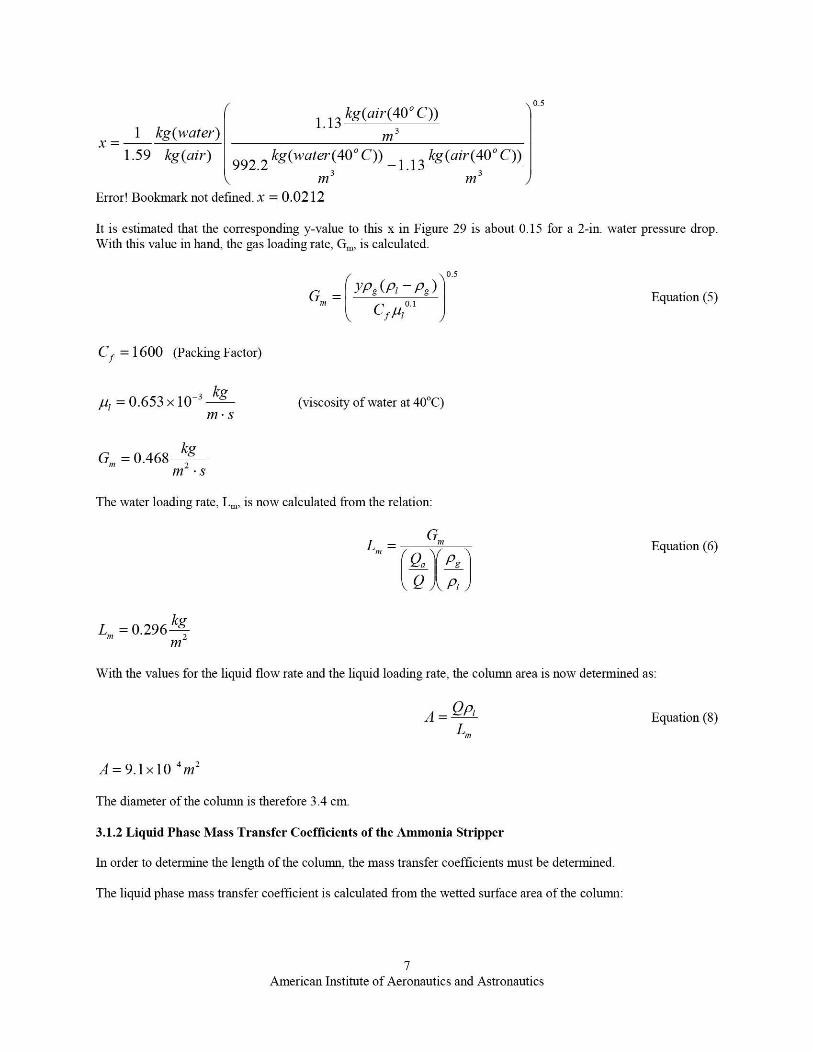
1.1 Design of an Ammonia Stripper - 99.8 Percent Removal of Ammonia
1.1.1 Flow Rates and Column Diameter
The modeling of the distillation of urine and humidity condensate was studied at a flow rate of 20 liters per hour(L/hour). For this reason, the wastewater flow rate through a stripper will be studied at the same flow rate. Thetemperature of the wastewater is estimated as 40 ` C. The first of the stripper designs examined was an anunoniastripper. Stripping has previously been used for the recovery of ammonia from trine [10]. Generally, an alkalinepH is preferred for ammonia stripping [11]. While the pH of the pretreated urine and humidity condensates isparticularly acidic prior to distillation, the pH could be increased in the distillate by systematic addition of lime. AtpH 10 and at 40 ^C, 95 percent of anm7onia is present as the gas. These conditions allow for successful removal ofanunonia from water with efficiency.
In surnmary, a colunni design is specified with the dimensions of 1.2 meters (m) in height and 1.7 cm in diameter.The gas pressure drop is 1630 pascals per meter (Pa/m). The gas flow rate is 0.508 kilograms per square meter(kg/m2). The liquid flow rate is 20 L/day. The stripping factor is 2. The packing is 6.35-mm diameter Raschigrings.
American Institute of Aeronautics and Astronautics
The packing factor for 6.35-mm ceramic Raschig rings is 1600 [12]. The dimensionless Henry's law constant foraininonia at 40 * C, H, is 0.001436 [46]. The minimum air-to-water ratio corresponds to the condition when theeffluent gas from the stripper is in equilibrium with the incoming water. It is represented as follows:
(
Q. — C° — CQ
Equation (1)Q in
HC,
The influent concentration of a mixed stream of urine and humidity condensate, as described in Appendix A. is 211mg,-L. The target concentration is 0.5 mg/L. In the equation above; the influent concentration is Co and the effluent(or target concentration is C z). The minimum air-to-water ratio under these conditions is calculated to be 695.
In the next part of the design study, the cross-sectional area for the packed tower is determined. In order to calculatethis value, the actual air-to-water ratio (taking into account the strippin g factor); the air pressure drop at half thevalue for flooding, the gas loading rate; and the liquid loading rate are required.
The air-to-water ratio was calculated with the following equation:
Q,, ^Q — Equation (2)
min Hammonia
Where S is the stripping factor (in this case, 2) and Hanm,muz is the dimensionless Henry's law constant for airunoniaat 40 C. The air-to-water ratio is calculated to be 1390.
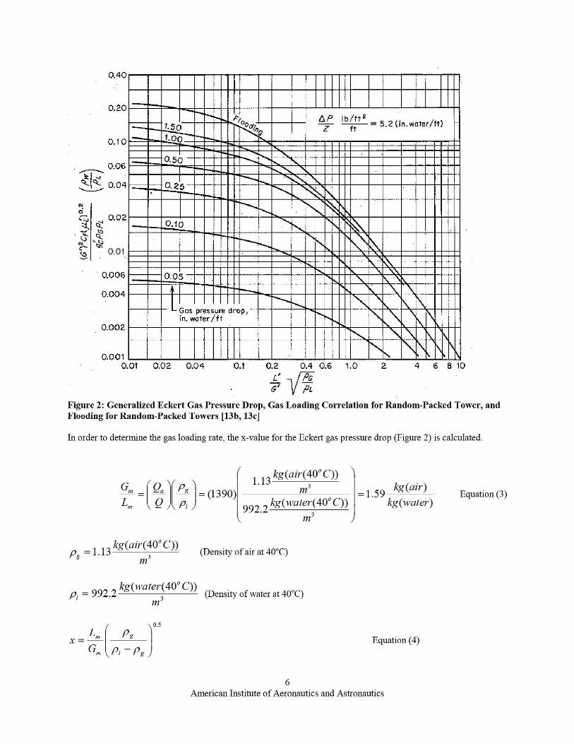
Raschig rings with a diameter of 6.35 nun are reported to have a pressure drop of 4 inches of water per foot atflooding [ 13a]. The pressure drop used will behalf of that value (1630 Pa%m`m). See Figure 29.
American Institute of Aeronautics and Astronautics
0.40
0.20
--1,50AP Ib/ft2Z ft
— 5.2 (in. water/ft)
0,10
0.06
0.04
NO♦„ 0.02
w.i7
N ^^0.01
0.006
0.004
OM2
0.50
0.25
0.10
o.os
Gas pressure drop,in. water/ft
0.001 I l i l{ t l t I I l 1] 1 1 1 1 I ^• T I r l IV
0.01 0.02 0.04 0.1 0.2 0.4 0.6 1.0 2 4 6 8 10
L' JTG
Figure 2: Generalized Eckert Gas Pressure Drop, Gas Loading Correlation for Random-Packed Tower, andFlooding for Random-Packed Towers [13b, 13c]
In order to deternune the gas loading rate, the x-value for the Eckert gas pressure drop (Figure 2) is calculated.
1.13kg(air(40°C))
3G""' = Qa Pg = (1390) m —= 1.59
kg(air)Equation (3)
L"' Q Pr 992. 2 kg(water(40°C)) kg(water)
M3
kg(air C))pg =1.13
(40 °3 (Density of air at 40°C)
rn
kg(water(40' C))Pr = 992 2 3 (Density of water at 40°C)
M
0.s
X = L,n )Og Equation (4)
G,,, Pr — Pg
6American Institute of Aeronautics and Astronautics
kg(ai7°(40° C))0.5
x=1 kg(water^)
1.13m 3
1.59 kg(air) 992. 2
kg(water(40° C)) _ 1. 13
kg(air(40° C))3 3
177 M
Error! Bookmark not defined. x = 0.0212
It is estimated that the corresponding y-value to this x in Figure 29 is about 0- 15 for a 2-in. water pressure drop.With this value in hand, the gas loading rate, G,,,, is calculated.
0.5
G = YPg (Pr O Pg )
Cff1r
C f = 1600 (Packing Factor)
Equation (5)
P, =0.653x 10⁻³ kg
I7I•s
G,,, = 0.468 kgI7r- • s
(viscosity of water at 40°C)
The water loading rate, L,,,, is now calculated from the relation:
GL,»
)(PP9,
L » = 0.296 kg177
Equation (6)
With the values for the liquid flow rate and the liquid loading rate, the column area is now determined as:
A = QPr
L,,,
A=9.1x10⁻⁴m2
The diameter of the column is therefore 3.4 cm.
3.1.2 Liquid Phase Mass Transfer Coefficients of the Ammonia Stripper
In order to deternune the length of the column, the mass transfer coefficients must be deternned.
The liquid phase mass transfer coefficient is calculated from the wetted surface area of the column:
Equation (8)
7American Institute of Aeronautics and Astronautics
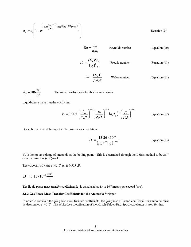
0 75-1.45 ` (Re)o.1 (Fr) -0.05 (we )U
L711, = at 1— e Equation (9)
Re= L
"' Reynolds number Equation (10)al,u,
2
Fr —_(Lm ) al
Froude number Equation (11)(p, )2 g
2
i'Ve = (L.) Weber number Equation (11)
PAU
za . =106 m3 The wetted surface area for this column design
M
Liquid-phase mass transfer coefficient:
213 -0.5 -1/3
kl = 0.005 1 L_
P1 (a
1
d )04 Pr Equation (12)
a ll-A PrDIP
Ag
Dl can be calculated through the Havduk-Laurie correlation:
_ 13.26 x 10⁻⁵
D1 — (P11 )1.14 (Vb
)0.589 Equation (1 )
Vb is the molar volume of ainmonia at the boiling point. This is determined through the LeBas method to be 26.7cubic centimeters (cm 3)iMole.
The viscosity of grater at 40'C, µl, is 0-563 cP.
2A=3.11x10
-5 cm
S
The liquid phase mass transfer coefficient, kl, is calculated as 8.4 x 10 -5 meters per second (m/s).
3.1.3 Gas Phase Mass Transfer Coefficients for the Ammonia Stripper
In order to calculate the gas phase mass transfer coefficients, the gas phase diffusion coefficient for ainmonia mustbe determined at 40 *C. The Wilke-Lee modification of the Hirsch-Felder-Bird-Spotz correlation is used for this:
8American Institute of Aeronautics and Astronautics
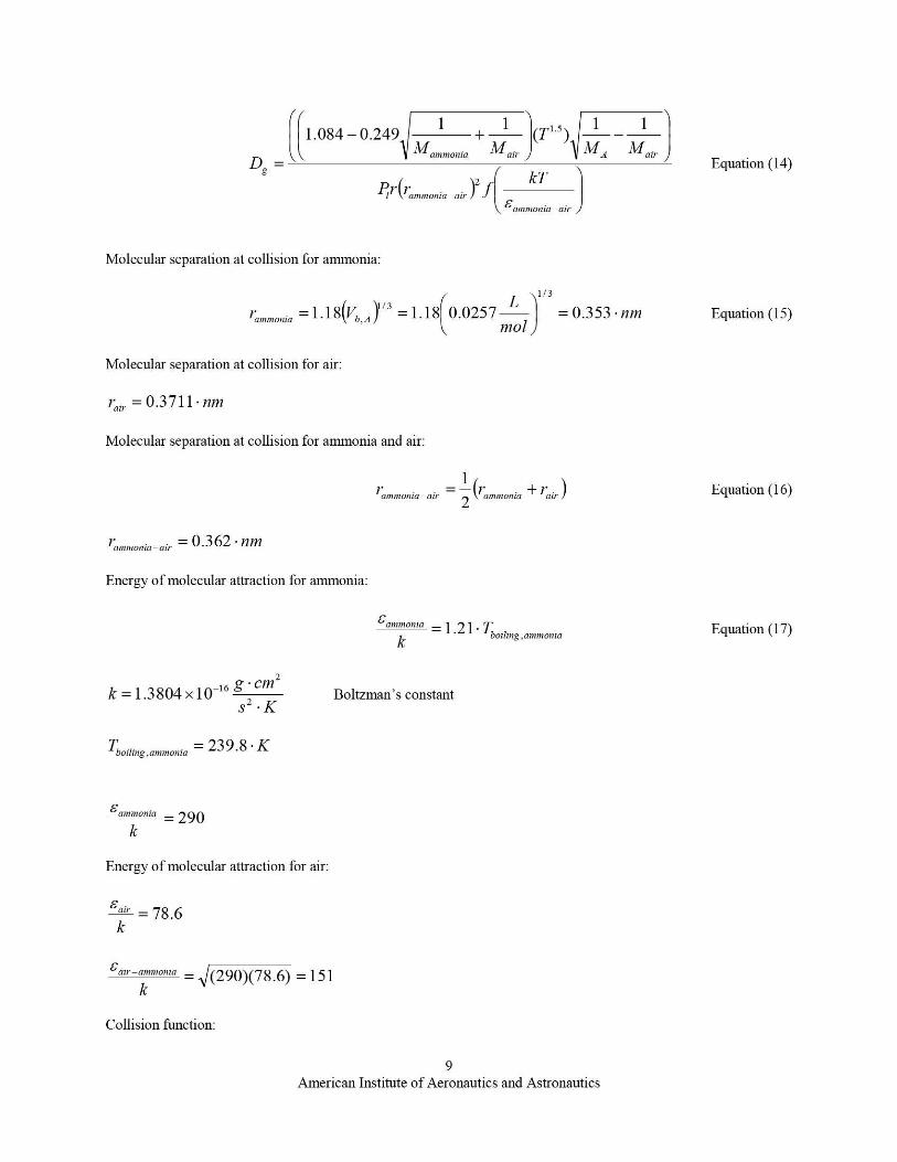
1.084 — 0.2491 + 1 (T1.5) 1 — 1
Mannnanin lair ^MA fairDg =
(( ll
Equation (14)
^ T l'ammonia-air /2 .fkT )
f' amwoMa -air
Molecular separation at collision for ammonia:
)1/3
y^mmania = 1.18(Vb A =1.18(0.0257 01
= 0.353 • nm Equation (15)
Molecular separation at collision for air:
I'ah. =0.3711• nm
Molecular separation at collision for ammonia and air:
inn»»onta-air — (ammonia + air' ^ Equation (16)
I a»maonia-air — 0.362 . nn7
Energy of molecular attraction for ammonia:
£a»mronia = 1 .21 • Tboiling.am Equation (17)k
monia
2
k =1.3804x 10⁻¹⁶ g. cms 2 -K
Tboiling,ammonia = 239.8 • K
Boltzman's constant
£amn1onia = 290
k
Energy of molecular attraction for air:
£air = 78.6k
£air-am»or,7a
k= (290)(78.6) =151
Collision function:
9American Institute of Aeronautics and Astronautics
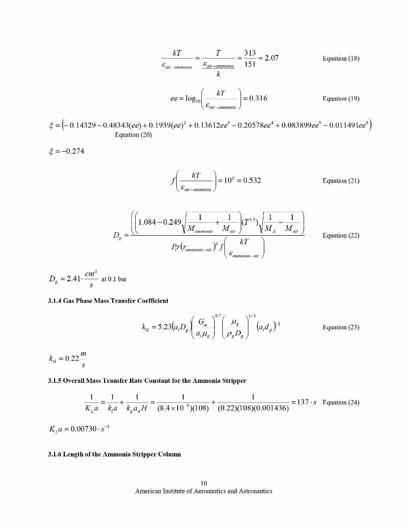
kT T 313= 2.07 Equation (18)
£air—mnmonia Canr—ammonin 151
k
ee = 109 10 kT = 0.316 Equation (19)£air—ammonia
_ 0.14329 — 0.48343(ee) + 0.1939(ee) 2 + 0.13612ee 3 — 0.20578ee 4 + 0.083899ee 5 —0.01 1 49 lee 6Equation (20)
^ _ —0.274
kTf
onia
=10' = 0.532 Equation (21)£air—amm
1.084 — 0.249FIV,
+ 1 (T, .5) 1 — 1onia 1 A ' a ir
Dg = Equation (22)
PI•(r•)2
f U1 nnmionia—airammonia—air
2
Dg =2.4l. cm
at 0.1 barS
3.1.4 Gas Phase Mass Transfer Coefficient
0.7 1/3
kG = 5.23(a,DGmfig
(ard Y2 Equation (23)g ar,ug PgDg
P
k =0.22 mS
3.1.5 Overall Mass Transfer Rate Constant for the Ammonia Stripper
1 1 + 1 — 15+
1=137-s Equation (24)
KLa kia kg a,,,H (8.4 x 10- )(108) (0.22)(108)(0.001436)
KL a = 0.00730 • s-'
3.1.6 Length of the Ammonia Stripper Column
10
American Institute of Aeronautics and Astronautics
L=S In
AKL a S —1
1+ Co
(S-1)
CTO
SEquation (25)
L=2x2.3x10 7.M In
9.1 x 10⁻⁴ (0.00730)
1+211
0.5 = 0.37 - m2
It has been demonstrated that removal of ammonia may be achieved at the target levels described in the beginning ofthis report for a colunmi, which is about 1 ft in height and 0.7 in. in diameter. This design is compatible with andrequires basic wastewater. One architecture, which may be worth considering, is to have an ammonia stripperupstream from a distillation column. In this way, ammrnonia can be removed along with other VOCs initially andthen organic acids (such as acetic acid) may be removed with the brine water at the distillation column.
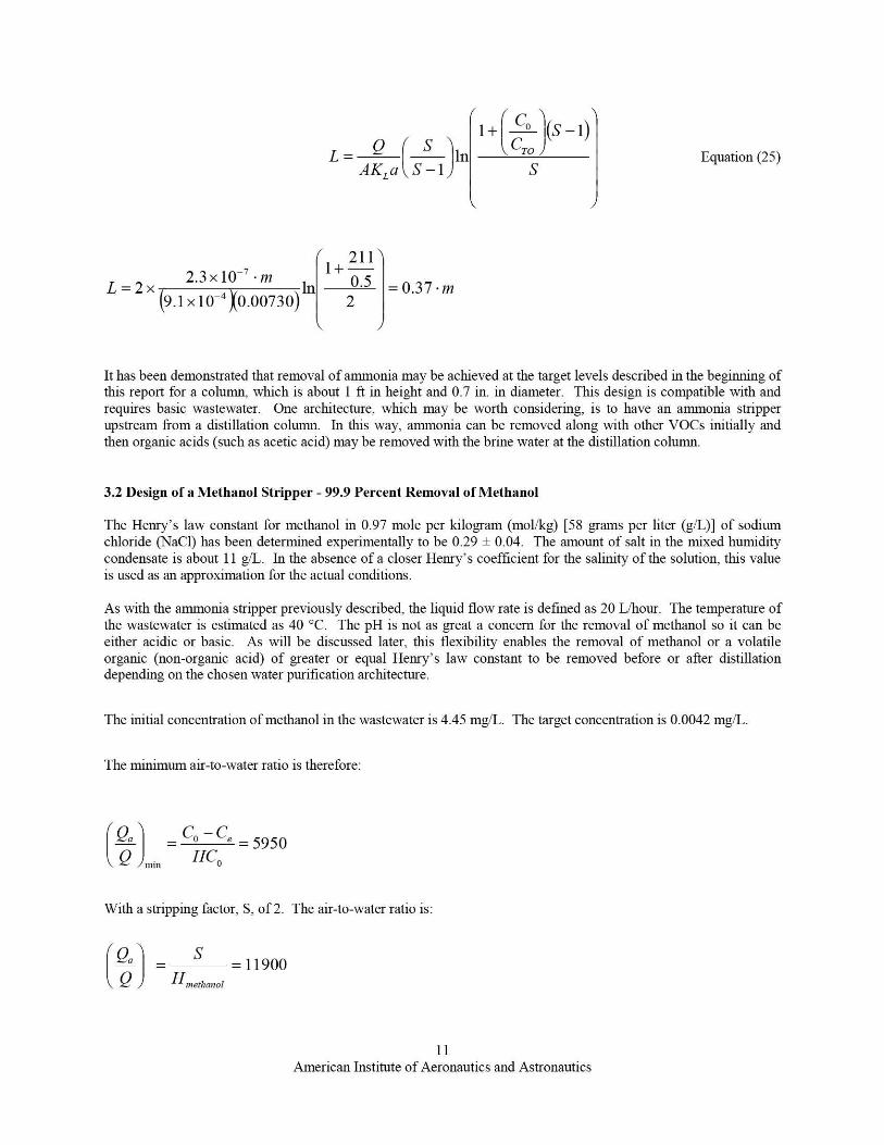
3.2 Design of a Methanol Stripper - 99.9 Percent Removal of Methanol
The Henry's law constant for methanol in 0.97 mole per kilogram (mol/kg) [58 grams per liter (g/L)] of sodiumchloride (NaCl) has been determined experimentally to be 0.29 f 0.04. The amount of salt in the mixed humiditycondensate is about 11 g/L. In the absence of a closer Henry's coefficient for the salinity of the solution, this valueis used as an approximation for the actual conditions.
As with the ammonia stripper previously described, the liquid flow rate is defined as 20 L/hour. The temperature ofthe wastewater is estimated as 40 °C. The pH is not as great a concern for the removal of methanol so it can beeither acidic or basic. As will be discussed later, this flexibility enables the removal of methanol or a volatileorganic (non-organic acid) of greater or equal Henry's law constant to be removed before or after distillationdepending on the chosen water purification architecture.
The initial concentration of methanol in the wastewater is 4.45 mg/L. The target concentration is 0.0042 mg/L.
The minimum air-to-water ratio is therefore:
`Gn — Cp — Ce = 5950
min HCO
With a stripping factor, S, of 2. The air-to-water ratio is:
Qn = S —11900Hnrerhanol
11American Institute of Aeronautics and Astronautics
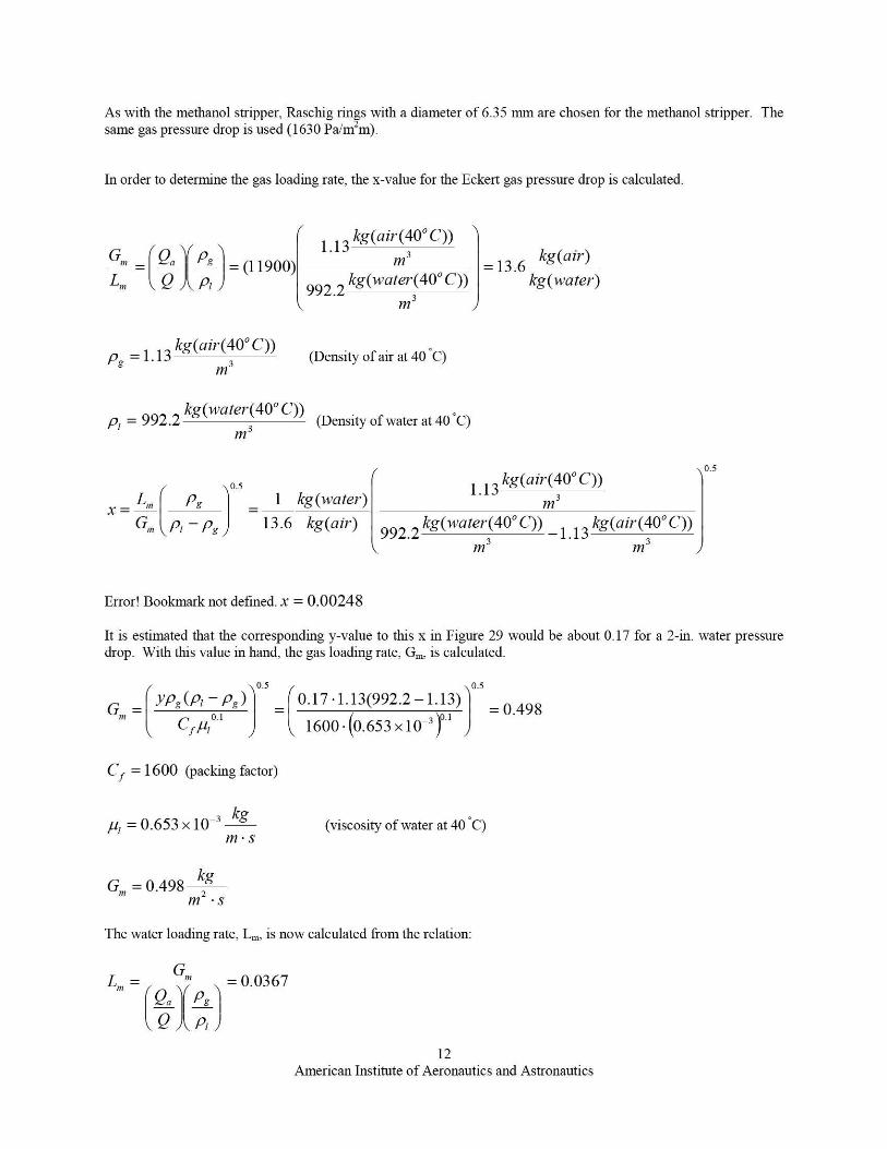
As with the methanol stripper, Raschig rings with a diameter of 6.35 mm are chosen for the methanol stripper. Thesame gas pressure drop is used (1630 Pa/1117'm).
In order to determine the gas loading rate, the x-value for the Eckert gas pressure drop is calculated.
1.13 kg(ah-(40°C))
Q° pg = (11900) m3L.
Q '°, 992.2 kg(w C))ater°(40°
m3
kg(air°(40°C))pg =1.13 3 (Density of air at 40'C)
M
kg(water^(40° C))p, = 992.2 3 (Density of water at 40'Q
M
kg(ah-)=13.6
kg(water)
0.5
x=
° 5 1.13 kg(ah-(40' C))
L 1 kg(water) m3_
G, p, — pg 13.6 kg(ah-) 992.2 kg(wate7°(40°C))
_ 1.13 kg(ah-(40°C))
3 3M m
Error! Bookmark not defined. x = 0.00248
It is estimated that the corresponding y-value to this x in Figure 29 would be about 0.17 for a 2-in. water pressuredrop. With this value in hand, the gas loading rate, G,,,, is calculated.
O.s 0.5
ypg (p, 0. pg ) 0.17-1.13(992.2-1.13)G„o = o.i = o.i = 0.498
C fA 1600 • (0.653 X 10 -3 )
Cf =1600 (packing factor)
u, = 0.653 X 10⁻³ k9m•s
G,,, = 0.498 kgM .s
(viscosity of water at 40'C)
The water loading rate, L,,,, is now calculated from the relation:
L» = G'» = 0.0367Q^ pg
Q Pr
12
American Institute of Aeronautics and Astronautics
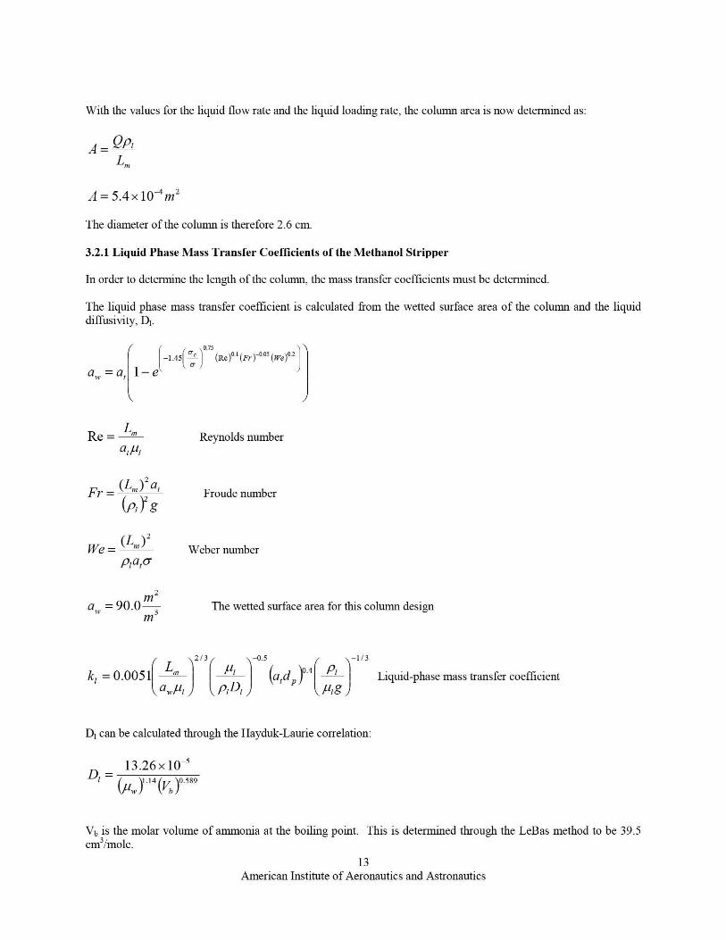
With the values for the liquid flow rate and the liquid loading rate, the column area is now determined as:
4 = QP1L.
.4=5.4x10 -4 n,2
The diameter of the column is therefore 2.6 cm.
3.2.1 Liquid Phase Mass Transfer Coefficients of the Methanol Stripper
In order to determine the length of the column, the mass transfer coefficients must be determined.
The liquid phase mass transfer coefficient is calculated from the wetted surface area of the column and the liquiddiffusivity, Dl.
f .7s
-1.45(-̀ 1o
(Re)o.I (F"
)-o.os
(we )0.2
a,,. =a t 1—e a
Re = L. Reynolds number01/11
z
Fr = (L"'^, a` Froude number
(PI) g
z
We = ^L'"^ Weber numberPAC
z
a . = 90.0 3 The wetted surface area for this column designm
2/3 -1/3
k, = 0.0051 " P1
-0.5
(a,d^,Y.4 P' Liquid-phase mass transfer coefficient
O.P1 P1 D, ,uzg
D, can be calculated throu gh the Hayduk-Laurie correlation:
_ 13.26 x 10⁻⁵
D7
\Uv \1.14
`Vb 10.589
Vv is the molar volume of almmonia at the boiling point. This is determined through the LeBas method to be 39.5cm3imole.
13
American Institute of Aeronautics and Astronautics
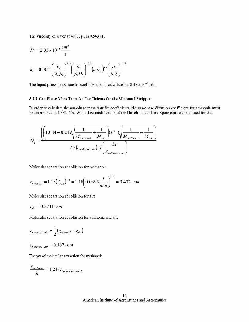
The viscosity of water at 40 _C, µ l, is 0.563 cP.
2
Dl = 2.93 x 10⁻⁵ cm
S
) 2/3 —0.5 —113
k, =0.0051 Lna f-^l (atdyl°4 P1
a ,rf^1 P1Dj ` J pig
The liquid phase mass transfer coefficient, k,, is calculated as 8.47 x 10 -6 m/s.
3.2.2 Gas-Phase Mass Transfer Coefficients for the Methanol Stripper
In order to calculate the gas-phase mass transfer coefficients, the gas-phase diffusion coefficient for ammonia mustbe determined at 40 *C. The Wilke-Lee modification of the Hirsch-Felder-Bird-Spotz correlation is used for this:
1.084-0.2491 + 1 /7.1.5\
^IhmwlD_Mmethanol ai,
111 M
,n Mai,Dg
2 kT
P' ^jnaetnanal-air .f£methmaol —air
Molecular separation at collision for methanol:
1/3
1 naetlaanol = 1.18(Vb , 13 =1.18 0.0395 L = 0.402 • nmmol
Molecular separation at collision for air:
Fair = 0.3711 . nm
Molecular separation at collision for almnonia and air:
methanol—air 2 k""Imnol + air,
1 naethanol—air — 0.387 . nm
Energy of molecular attraction for methanol:
£methanol = 1.21 , TUoiling.methanolk
14
American Institute of Aeronautics and Astronautics
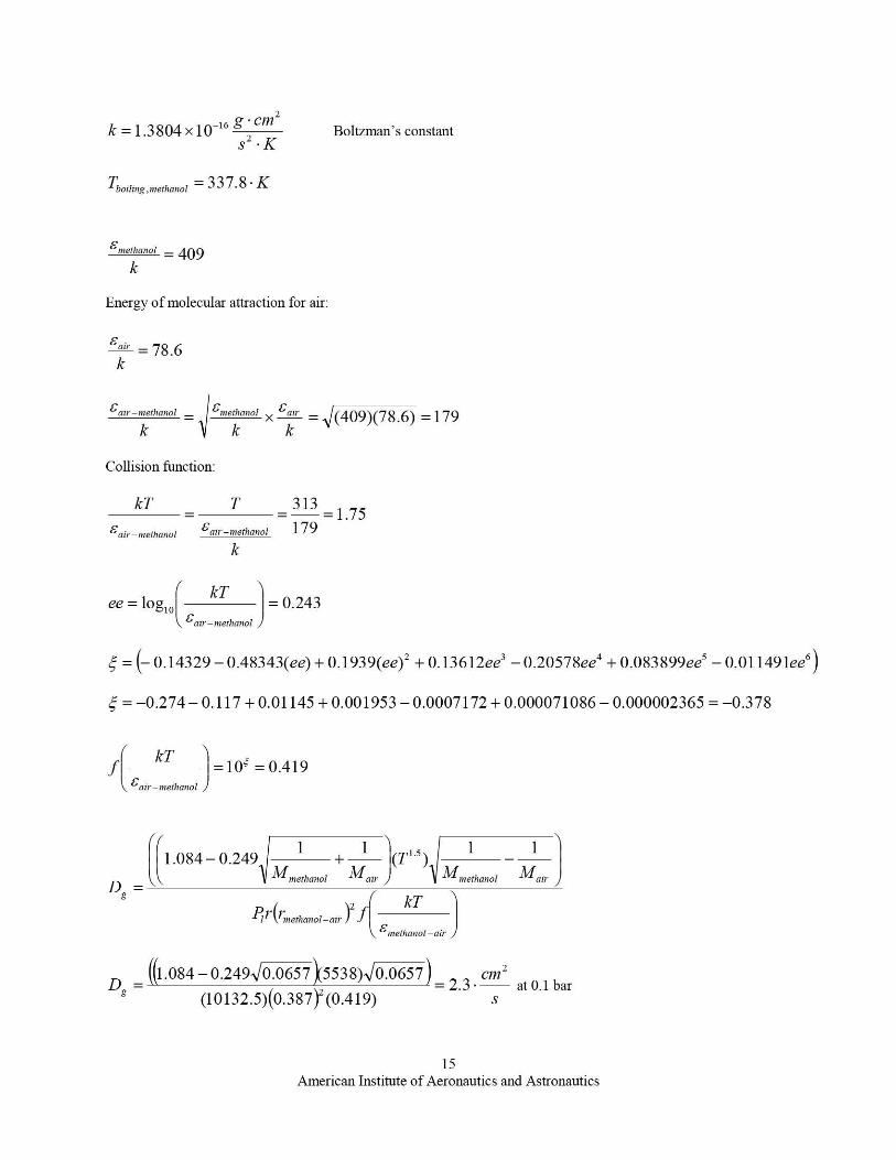
k =1.3804 x 10⁻¹⁶ g cm z
Boltzman's constantS • K
Tboiling,methanol 337.8 . K
£methanol --409k
Energy of molecular attraction for air:
"" = 78.6k
£air—methanol _ £methanol x £ah = (409)(78.6) =179k k k
Collision function:
kTT 313_ _ =1.75£air—methanol Con—methanol 179
k
ee = log,,, kT = 0.243irn£a —ethanol )
5 = 0.14329 — 0.48343(ee) + 0.1939(ee) 2 + 0.13612ee 3 — 0.20578ee4 + 0.083899ee 5 — 0.01149 lee 6)
5 = —0.274 — 0.117 + 0.01145 + 0.001953 — 0.0007172 + 0.000071086 — 0.000002365 = —0.378
kTf =10' = 0.419
Fair—methanol )
1.084 — 0.249FM
+ 1 (T1.5)
D
1 _ 1
_ nol Mai,
1Mmethanol Mair
Dg
P11' Y'methanoi—air z JkT
£methanol —air
— ((1 - 084-0.249 0.0657 k5538) 0.0657 — Cm2D — —g (10132.5)(0.387 )2
2.3 -
(0.419) s at 0.l bar
15American Institute of Aeronautics and Astronautics
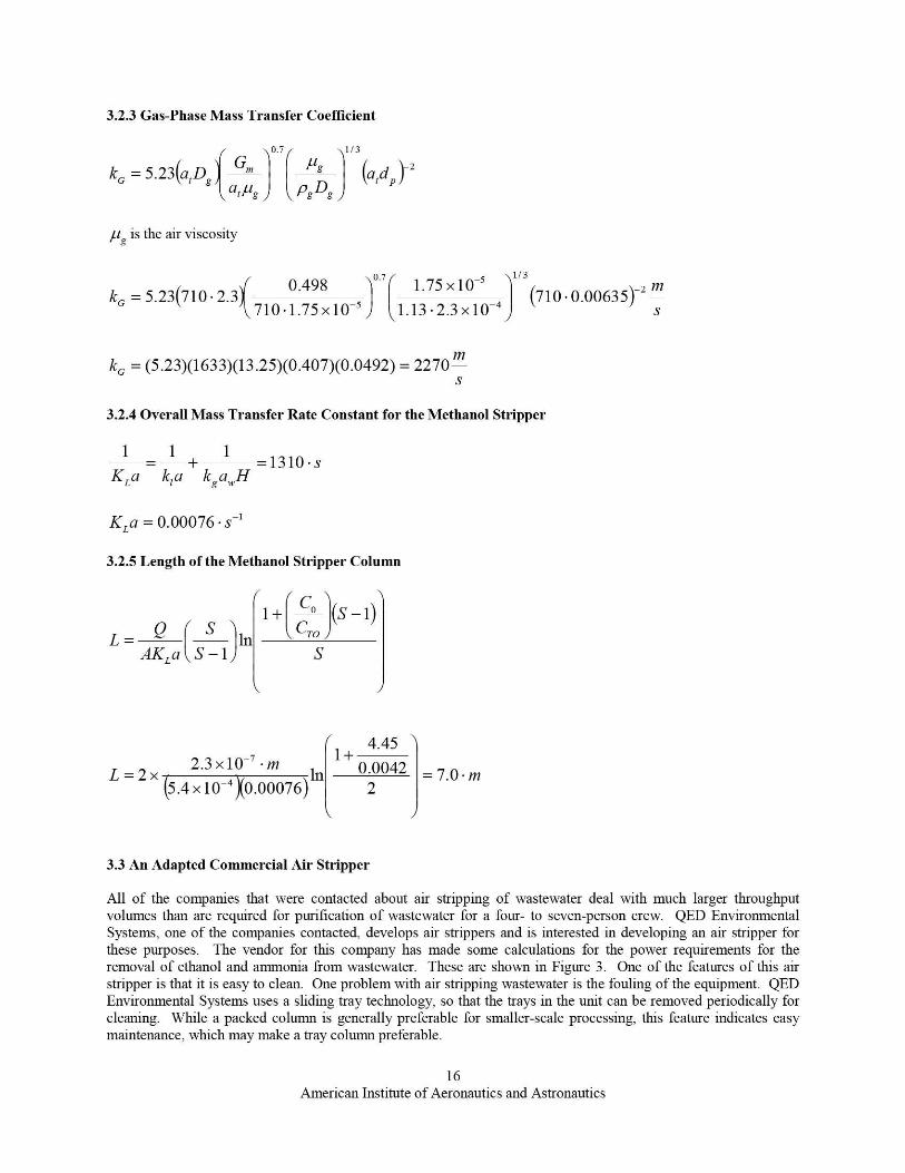
3.2.3 Gas-Phase Mass Transfer Coefficient
0.7 1 / 3
k = 5.23(a,L g G (a do r2
anus ogDg
,ug is the air viscosity
k = 5.23710 . 2.3 N0.498 1. 7 1.75 x 10⁻⁵
710 . 1.75x10') 1.13.2.3x10-4
1/3
(710.0.00635)-2 mS
kG = (5.23)(1633)(13.25)(0.407)(0.0492) = 2270 m
3.2.4 Overall Mass Transfer Rate Constant for the Methanol Stripper
1 — I + 1 =1310•sKLa k,a kga,,,H
KL a = 0.00076 • s-1
3.2.5 Length of the Methanol Stripper Column
S
I+( ^° (S-1)L = In
ro
AKLa S —1 S
4.45
L=2x2.3x40-7 m In
1+0.0042 =7.0•m
5.4 x 10 0.00076) 2
3.3 An Adapted Commercial Air Stripper
All of the companies that were contacted about air stripping of wastewater deal with much larger throughputvolumes than are required for purification of wastewater for a four- to seven-person crew. QED EnvironmentalSystems, one of the companies contacted, develops air strippers and is interested in developing an air stripper forthese purposes. The vendor for this company has made some calculations for the power requirements for theremoval of ethanol and arrnnonia from wastewater. These are shown in Figure 3. One of the features of this airstripper is that it is easy to clean. One problem with air stripping wastewater is the fouling of the equipment. QEDEnvironmental Systems uses a sliding tray technology, so that the trays in the unit can be removed periodically forcleaning. While a packed column is generally preferable for smaller-scale processing, this feature indicates easymaintenance, which may make a tray column preferable.
16
American Institute of Aeronautics and Astronautics
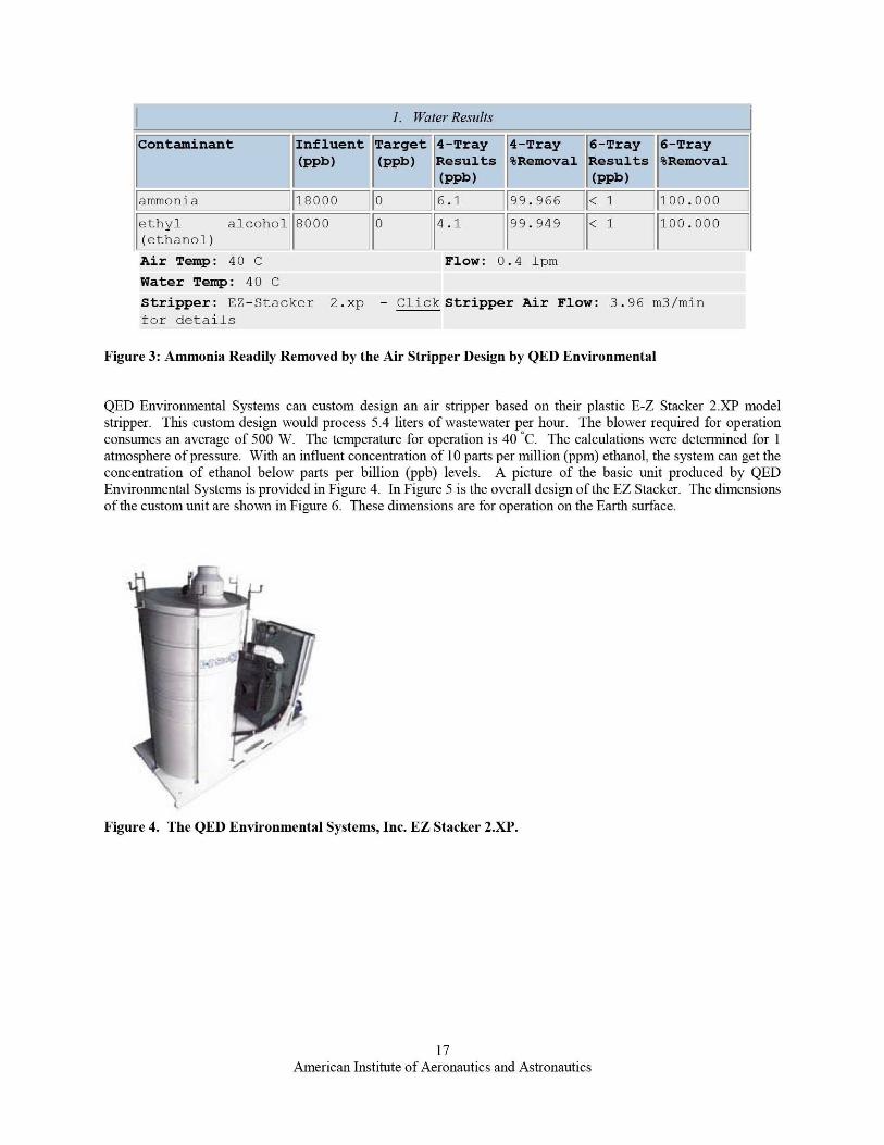
1. Water Results
Contaminant Influent Target 4-Tray 4-Tray 6-Tray 6-Tray(ppb) (ppb) Results %Removal Results %Removal
(ppb ) _ f _`(ppb)
ammonia 18000 +0 ^6.1 99.966 < 1 100.000
ethyl alcohol 80004.1 99.949 < 1 `100.000(ethanol)
I^ II
Air Temp: 40 C Flow: 0.4 1pmWater Temp: 40 CStripper: EZ-Stacker 2.xp - Click Stripper Air Flow: 3.96 m3/minF--
Figure 3: Ammonia Readily Removed by the Air Stripper Design by QED Environmental
QED Environmental Systems can custom design an air stripper based on their plastic E-Z Stacker 2-XP modelstripper. This custom design would process 5.4 liters of wastewater per hour. The blower required for operationconsumes an average of 500 W. The temperature for operation is 40 'C. The calculations were determined for 1atmosphere of pressure. With an influent concentration of 10 parts per million (ppm) ethanol, the system can get theconcentration of ethanol below parts per billion (ppb) levels. A picture of the basic unit produced by QEDEnvironmental Systems is provided in Figure 4. In Figure 5 is the overall design of the EZ Stacker. The dimensionsof the custom unit are show i in Figure 6. These dimensions are for operation on the Earth surface.
Figure 4. The QED Environmental Systems, Inc. EZ Stacker 2.XP.
17
American Institute of Aeronautics and Astronautics
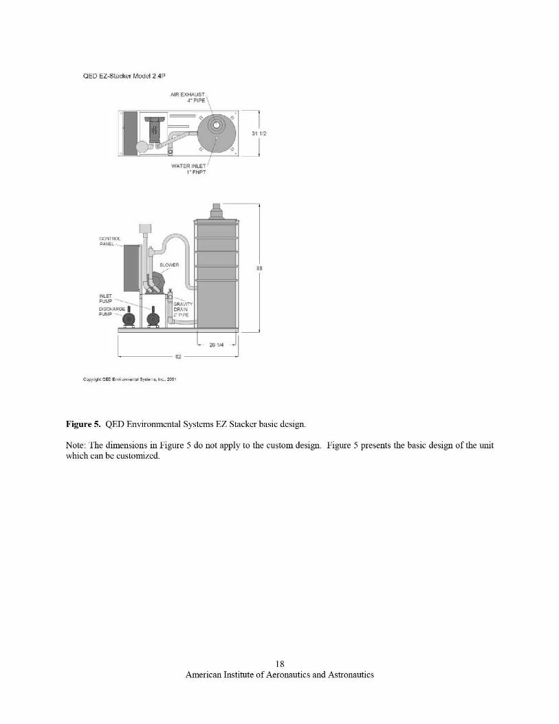
131 1121
I- 82 -
CONTFPANEL
1\LETPUMP
DISMPU61P
sa
QED EZ-Stacker Model 2AP
AIR FXHAI J.CT
WATER INLET1" FNPT
CQPYNhc OED Envifaallantal Systems. rnc.. 2411
Figure 5. QED Environmental Systems EZ Stacker basic design.
Note: The dimensions in Figure 5 do not apply to the custom design. Figure 5 presents the basic design of the unitwhich can be customized.
18American Institute of Aeronautics and Astronautics
56"
r
IT0 2 0"
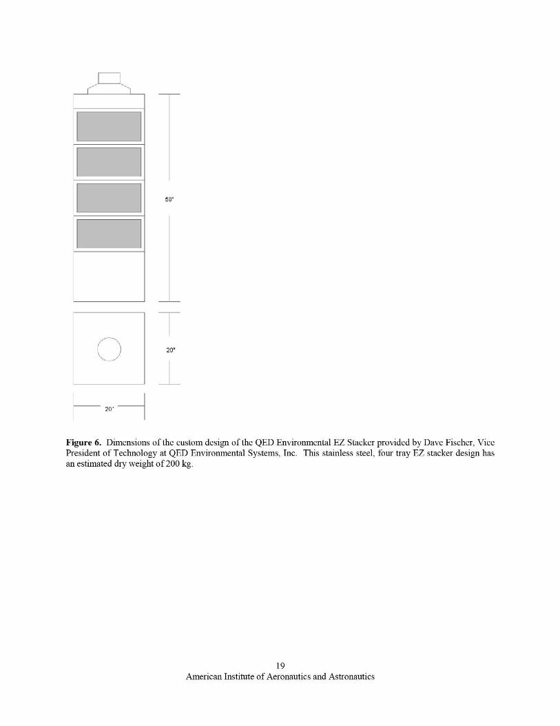
Figure 6. Dimensions of the custom design of the QED Environmental EZ Stacker provided by Dave Fischer, VicePresident of Technology at QED Environmental Systems, Inc. This stainless steel, four tray EZ stacker design hasan estimated dry weight of 200 kg.
19American Institute of Aeronautics and Astronautics
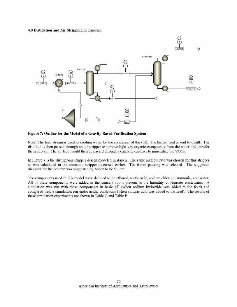
4.0 Distillation and Air Stripping in Tandem
Figure 7: Outline for the Model of a Gravity-Based Purification System
Note: The feed stream is used as cooling water for the condenser of the still. The heated feed is sent to distill. Thedistillate is then passed through an air stripper to remove light key organic compounds from the water and transferthem into air. The air feed would then be passed through a catalytic oxidizer to mineralize the VOCs.
In Figure 7 is the distiller-air stripper design modeled in Aspen. The same air flow rate was chosen for this stripperas was calculated in the ammonia stripper discussed earlier. The 6-mm packing was selected. The suggesteddiameter for the column was suggested by Aspen to be 5.3 cm. yy
The components used in this model were decided to be ethanol, acetic acid, sodium chloride, ammonia, and water.All of these components were added in the concentrations present in the humidity condensate wastewater. Asimulation was run with these components in basic pH (when sodium hydroxide was added to the feed) andcompared with a simulation run under acidic conditions (when sulfuric acid was added to the feed). The results ofthese simulation experiments are shown in Table O and Table P.
20American Institute of Aeronautics and Astronautics
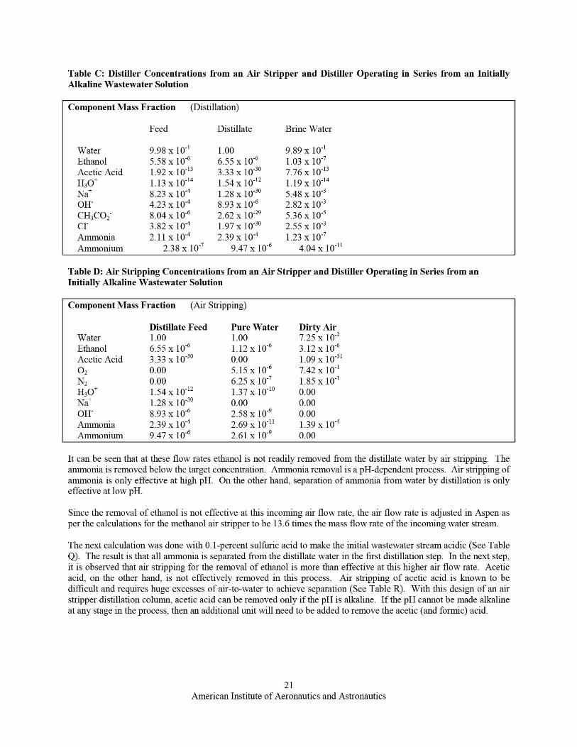
Table C: Distiller Concentrations from an Air Stripper and Distiller Operating in Series from an InitiallyAlkaline «'astewater Solution
Component Mass Fraction (Distillation)
Feed Distillate Brine Water
Water 9.98 x 10 -1 1.00 9.89 x 10-'Ethanol 5.58 x 10 -6 6.5.5 x 10"6 1.03 x 10 -7
Acetic Acid 1.92 x 10"13 3.33 x 10 -30 7.76 x 10"13H30+ 1.13 x 10⁻¹⁴ 1.54 x 10⁻¹² 1.19 x 10"14
Na+ 8.23 x 10⁻⁴ 1.28 x 10⁻³⁰ 5.48 x 10"3OH" 4.23 x 10 -4 8.93 x 10⁻⁶ 2.82 x 10⁻³CH3CO2 8.04 x 10 -6 2.62 x 10⁻²⁹ 5.36 x 10'5Cl 3.82x10⁴ 1.97x1030 2.55x10³Annnonia 2.11 x 10 -4 2.39 x 10⁻⁴ 1.23 x 10 -7
Amnnonium 2.38 x 10 -7 9.47 x 10 -6 4.04 x 10 -11
Table D: Air Stripping Concentrations from an Air Stripper and Distiller Operating in Series from anInitially Alkaline Wastewater Solution
Component Mass Fraction (Air Stripping)
Distillate Feed Pure Water Dirty AirWater 1.00 1.00 7.25 x 10⁻²
Ethanol 6.55 x 10 -6 1.12 x 10⁻⁶ 3.12 x 10⁻⁶
Acetic Acid 3.33 x 10 -30 0.00 1.09 x 10-3102 0.00 5.15 x 10⁻⁶ 7.42 x 10-'N2 0.00 6.25 x 10 -7 1.85 x 10-'H30+ 1.54 x 10⁻¹² 1.37 x 10⁻¹⁰ 0.00Na+ 1.28 x 100 0.00 0.00OH- 8.93 x 10⁻⁶ 2.58 x 10⁻⁹ 0.00Aninonia 2.39 x 10⁻⁴ 2.69 x 10⁻¹¹ 1.39 x 10⁻⁴
Arrimonium 9.47 x 10 -6 2.61 x 10 -9 0.00
It can be seen that at these flow rates ethanol is not readily removed from the distillate water by air stripping. Theannrnonia is removed below the target concentration. Ammonia removal is a pH-dependent process. Air stripping ofammonia is only effective at high pH. On the other hand, separation of ammonia from water by distillation is onlyeffective at low pH.
Since the removal of ethanol is not effective at this incoming air flow rate, the air flow rate is adjusted in Aspen asper the calculations for the methanol air stripper to be 13.6 times the mass flow rate of the incoming water stream.
The next calculation was done with 0.1-percent sulfuric acid to make the initial wastewater stream acidic (See TableQ). The result is that all ammonia is separated from the distillate water in the first distillation step. In the next step,it is observed that air stripping for the removal of ethanol is more than effective at this higher air flow rate. Aceticacid, on the other hand, is not effectively removed in this process. Air stripping of acetic acid is known to bedifficult and requires huge excesses of air-to-water to achieve separation (See Table R). With this design of an airstripper distillation column, acetic acid can be removed only if the pH is alkaline. If the pH cannot be made alkalineat any stage in the process, then an additional unit will need to be added to remove the acetic (and formic) acid.
21American Institute of Aeronautics and Astronautics
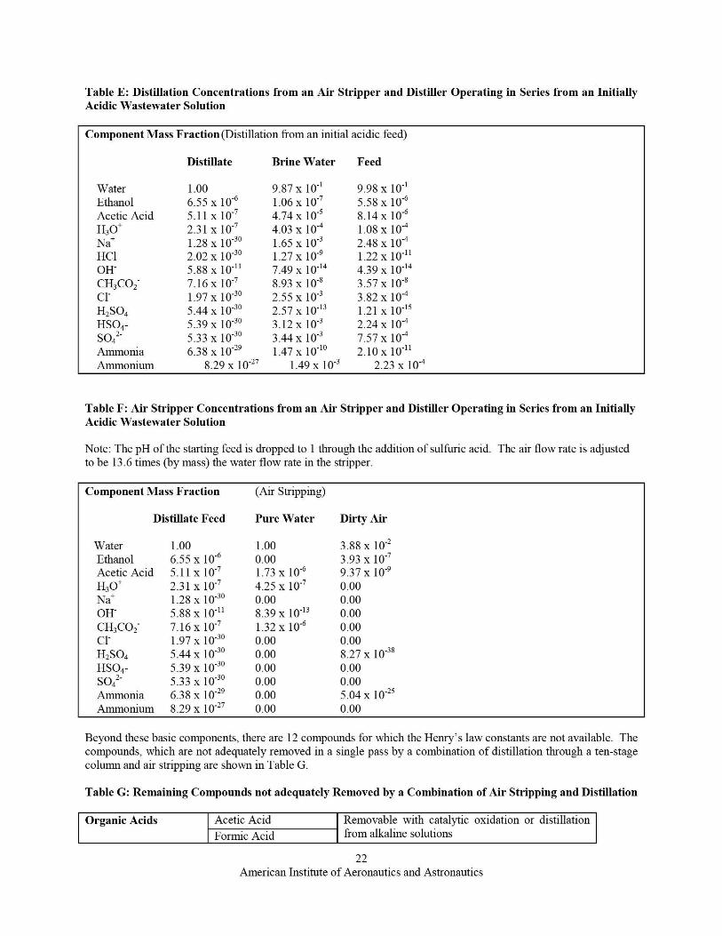
Table E: Distillation Concentrations from an Air Stripper and Distiller Operating in Series from an InitiallyAcidic Wastewater Solution
Component Mass Fraction (Distillation from an initial acidic feed)
Distillate Brine Water Feed
Water 1.00 9.87 x 10 -1 9.98 x 10 -1
Ethanol 6.5.5 x 10 -6 1.06 x 10 -7 5.58 x 10 -6
Acetic Acid 5.11 x 10 -7 4.74 x 10 -5 8.14 x 10 -6
H30+ 2.31 x 10⁻⁷ 4.03 x 10⁻⁴ 1.08 x 10"4Na+ 1.28 x 10⁻³⁰ 1.6.5 x 10-3 2.48 x 10⁻⁴HCl 2.02 x 10 -30 1.27 x 10⁻⁹ 1.22 x 10 -11
011" 5.88 x 10 -11 7.49 x 10⁻¹⁴ 4.39 x 10⁻¹⁴CH3 CO2 7.16 x 10⁻⁷ 8.93 x 10-' 3.57 x 10-'Cl 1.97X1030 2.55x10³ 3.82x10⁴H2 SO4 5.44 x 10⁻³⁰ 2.57 x 10⁻¹³ 1.21 x 10 -15
HSO4- 5.39 x 10 -30 3.12 x 10 -3 2.24 x 10-45042 5.33x1030 3.44x10³ 7.57x10⁴Annnonia 6.38 x 10 -29 1.47 x 10⁻¹⁰ 2.10 x 10⁻¹¹Annnonium 8.29 x 10 -27 1.49 x 10 -3 2.23 x 10⁻⁴
Table F: Air Stripper Concentrations from an Air Stripper and Distiller Operating in Series from an InitiallyAcidic Wastewater Solution
Note: The pH of the starting feed is dropped to 1 through the addition of sulfuric acid. The air flow rate is adjustedto be 13.6 times (by mass) the water flow rate in the stripper.
Component Mass Fraction (Air Stripping)
Distillate Feed Pure Water Dirty Air
Water 1.00 1.00 3.88 x 10⁻²
Ethanol 6.55 x 10 -6 0.00 3.93 x 10⁻⁷
Acetic Acid 5.11 x 10⁻⁷ 1.73 x 10⁻⁶ 9.37 x 10⁻⁹
H30+ 2.31 x 10-' 4.25 x 10-' 0.00Na+ 1.28 x 100 0.00 0.00OH 5.88 x 10 -" 8.39 x 10-" 0.00CH3CO2- 7.16 x 10-' 1.32 x 10⁻⁶ 0.00Cl 1.97 x 10 30 0.00 0.00H2 SO4 5.44 x 100 0.00 8.27 x 10"38HSO4- 5.39 x 100 0.00 0.00SO4
2- 5.33 x 100 0.00 0.00Ammonia 6.38 x 10 -29 0.00 5.04 x 10 -21
Annnonium 8.29 x 10⁻²⁷ 0.00 0.00
Beyond these basic components, there are 12 compounds for which the Henry's law constants are not available. Thecompounds, which are not adequately removed in a single pass by a combination of distillation through a ten-stagecolumn and air stripping are shown in Table G.
Table G: Remaining Compounds not adequately Removed by a Combination of Air Stripping and Distillation
Organic Acids Acetic Acid Removable with catalytic oxidation or distillationFormic Acid from alkaline solutions
22American Institute of Aeronautics and Astronautics
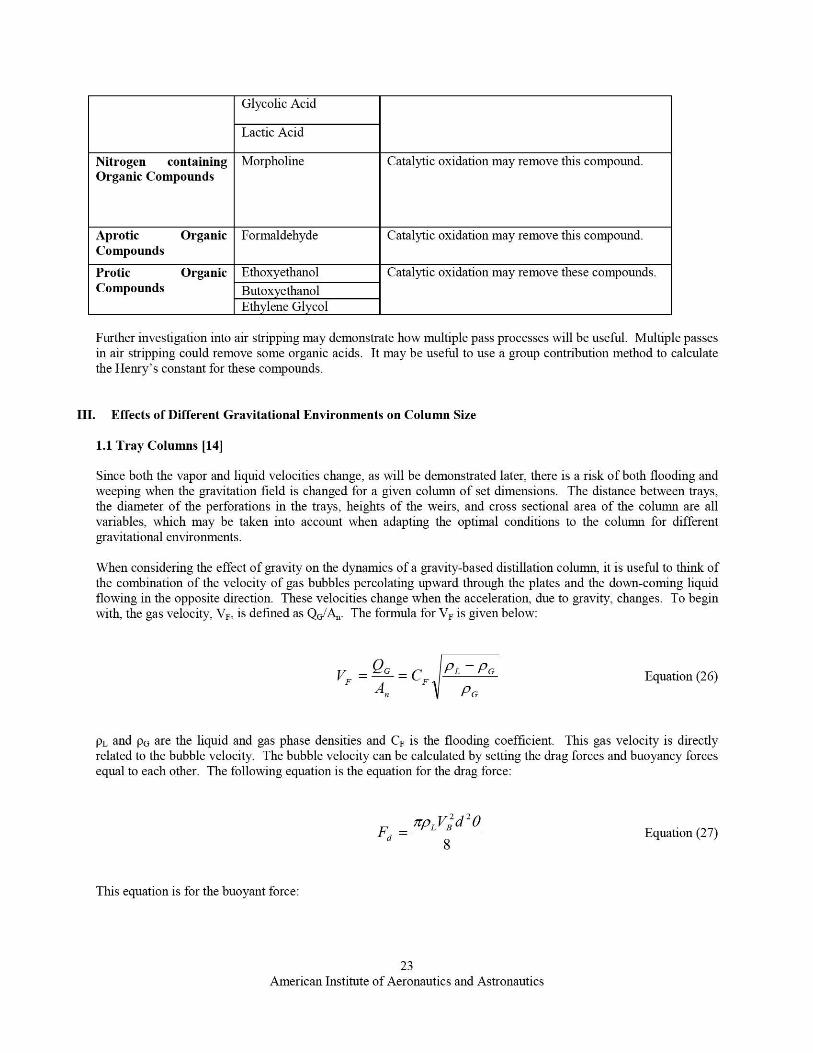
Glycolic Acid
Lactic Acid
Nitrogen containingOrganic Compounds
Morpholine Catalytic oxidation may remove this compound.
Aprotic OrganicCompounds
Formaldehyde Catalytic oxidation may remove this compound.
Protic OrganicCompounds
Ethoxyethanol Catalytic oxidation may remove these compounds.Butox ethanolEthvlene Glycol
Further investigation into air stripping may demonstrate how multiple pass processes will be useful. Multiple passesin air stripping could remove some organic acids. It may be useiill to use a group contribution method to calculatethe Henry's constant for these compounds.
III. Effects of Different Gravitational Environments on Column Size
1.1 Tray Columns [14]
Since both the vapor and liquid velocities change, as will be demonstrated later, there is a risk of both flooding andweeping when the gravitation field is changed for a given column of set dimensions. The distance between trays;the diameter of the perforations in the trays, heights of the weirs; and cross sectional area of the colunul are allvariables, which may be taken into account when adapting the optimal conditions to the column for differentgravitational environments.
When considering the effect of gravity on the dynamics of a gravity-based distillation column, it is useful to think ofthe combination of the velocity of gas bubbles percolating upward throu gh the plates and the down-coming liquidflowing in the opposite direction. These velocities change when the acceleration, due to gravity, changes. To beginwith, the gas velocity, VF, is defined as QG/A,,. The formula for VF is given below:
^G PL _PG
VF _ = C F Equation (26)A, 1 PG
PL and pc, are the liquid and gas phase densities and CF is the flooding coefficient. This gas velocity is directlyrelated to the bubble velocity. The bubble velocity can be calculated by setting the drag forces and buoyancy forcesequal to each other. The following equation is the equation for the drag force:
rcpL VB Zd 8Fd = Equation (27)
8
This equation is for the buoyant force:
23American Institute of Aeronautics and Astronautics
_ CPL PG )g,- 3
Fb6
Equation (28)
A^G
^^
Equation (31)
An i Sz
A„ z giEquation (32)
(Ad )2 PL g^L
tc8,uLEquation (33)
After setting Equations 6 and 7 equal to each other and solving for V B, the following equation is obtained:
Error! Bookmark not defined. VB 36
= 4dg PL —
PL
PG Equation uation 29)
From Equation 8 it follows that
VB a ^ Equation (30)
Since from Equation 5 k=Ag/VF , and since VB is proportional to VF, the following equation must hold true:
If the colunui pressure, feed, and reflux ratio are kept constant, then Q G will be the same between Earth, Mars, andthe Moon. From here one can obtain a generalized ratio for how the area scales from one lunar or planetary body (1)to the next (2):
Scaling the area of the downer is now of interest. In order to do this one must consider the liquid flow rate, QL.The equation for the rate of laminar flow due to gravity in a vertical pipe is as follows:
From this equation one sees the same relation as inverse proportionality between area, A, and the square root ofacceleration due to gravity, g, as in Equation 10. See the following equation:
1Error! Bookmark not defined. Ad oc Equation (34)
Similarly to Equation 11, the scaling ratio is:
24American Institute of Aeronautics and Astronautics
V i/zKL a(a^ Equation (40)
Error! Bookmark not defined. Ad '
=ri^ Equation (35)
Ad 2
Taking Equation 9, one can determine the ratio of bubble velocities to be as follows:
V B i F'^ 2
Equation (36)
VB 2 2
Thus, Equations 12, 15, 16 provide the scaling ratios for the plate area, downer area, and bubble velocity for agravity-based column on one heavenly body to another.
In designing a column, one can determine the size of the perforations in each plate and optimize them for thegravitational force experienced by the different droplets. For this reason the following relation is also ofimportance:
Mg 1W9i = 2 Equation (37)
6D 6D
Taking into account the diameter of the perforations, we are interested in calculating how column efficiencies maybe affected by changes in gravitational field. Equation 5 is a useful proportionality in this regard. From thisproportionality, the ratio of the ln(E) on celestial body 1 to celestial body 2 can be determined to be:
ln(1- E) Ja i hi kL VB 2Error! Bookmark not defined. Equation
ln(1- E) z az h kL 2 VB
(38)
To get to the perforation diameter, one needs to consider them to have a direct influence on the bubble diameter.Then the bubble mass transfer coefficient can be reviewed to get a relation for how the mass transfer relates tochanges in bubble contact time in the liquid, which is related to the bubble diameter.
iiz
Kr = Dab Equation (39)^zt
t is the bubble contact time in Equation 19. The contact time for the bubble in the liquid is going to be proportionalto the size of the bubble divided by its velocity.
Taking the ratio of Ki, between two bodies, 1 and 2, and substituting into Equation 18 gives Equation 21.
ln(1-E) 1 al h l d2 )112(
VB z
ln(1- E) z a2 h2 dl VB 1Equation (41)
1.2 Randomly-Packed Columns [151
25American Institute of Aeronautics and Astronautics
Thus far, only the general case for distillation with plates has been discussed. If distillation is looked at on a small-scale basis, the best option is to use a fractional column with some kind of packing.
The way Pettit (1986) determined the scaling factors in the case of random packing was to consider the liquid flowas laminar flow and the sum of a group of "filmlets." Between all these filmlets is gas flowing in the oppositedirection. From this, the volumetric flow of a given individual filmlet is:
Q f a b 3 Wr g Cos '3 Equation (42)
From this equation 6 is the total film thickness, Wf is the filmlet width, and P is the fihnnlet angle to the direction ofgravitational pull. Summing the filmlets according the cross-sectional area will help achieve a cross-sectionalpacking area. To sum up the filmlets, the total width of all the filmlets must be IA,, were 1 is the length of wettedpacking surface per unit of cross sectional area and A, is the cross sectional area of the column. 1 and R areindependent of gravity -- their values depend on the packing material. Hence, the proportionality of concern for thisstudy is:
Qz = J'A,g Equation (43)
If one makes the assumption that the filmlet thicknesses do not change when changing the acceleration due togravity and if QL is constant, the scaling ratio for change in liquid area is:
A° ' = 92 Equation (44)AC z gi
It is now important to scale in relation to the gas flow. In order to determine these relations, Pettit (1986) equatedthe drag force and the gravitational force as he did previously with the bubble colummns. Pettit found that theinterface for turbulent gas flow is proportional to a fVz, where V is the gas velocity and o f is the film area parallel tothe gas flow (see Darcy friction factor). The gravitational force from the liquid is proportional to ga f6 where af5 isthe column of liquid contained in the packed bed. Equating the drag force and gravity forces one gets this equation:
fizA, f gz Equation (45)A, z gi ^
With this scaling factor for gas one gets that the lunar column area will increase by a factor of 2.45. If the scalingfactor for liquid is used, the factor for scaling to the Moon will increase the column diameter by 6.
1.3 Moon-Adapted Distillers and Air Strippers
From Section 5.2, scaling gravitational effects according to the gas flow rate and scaling according to the liquid flowrate in a packed column give two different results. It may be necessary to run computational fluid dynamicscalculations to get a clearer picture of what the requirements would be for a packed column. The data presentedbelow (see Table H) describing scaled distillation columns for use on the lunar surface shows a range. The low endof the range is from the scaling factor of 2.45 for the gas-flow scaled column and the high end of the range is thescaling factor, 6, as calculated for the liquid-scaled column. The liquid scaling factor provides a more conservativeestimate for the column design so as to avoid flooding.
26American Institute of Aeronautics and Astronautics
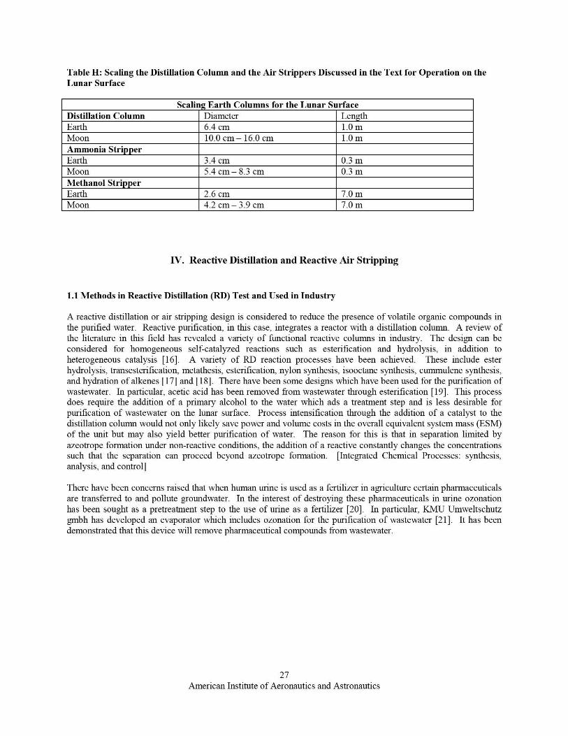
Table H: Scaling the Distillation Column and the Air Strippers Discussed in the Teat for Operation on theLunar Surface
Scaling Earth Columns for the Lunar SurfaceDistillation Column Diameter LenathEarth 6.4 cm 1.0 mMoon 10.0 cm— 16.0 cm 1.0 mAmmonia StripperEarth 3.4 cm 0.3 mMoon 5.4 cm— 8.3 cm 0.3 mMethanol StripperEarth 2.6 cm 7.0 mMoon 4.2 cm — 3.9 cm 7.0 in
IV. Reactive Distillation and Reactive Air Stripping
1.1 Methods in Reactive Distillation (RD) Test and Used in Industry
A reactive distillation or air stripping design is considered to reduce the presence of volatile organic compounds inthe purified water. Reactive purification, in this case, integrates a reactor with a distillation column. A review ofthe literature in this field has revealed a variety of functional reactive colunms in industry. The design can beconsidered for homogeneous self-catalyzed reactions such as esterification and hydrolysis, in addition toheterogeneous catalysis [16]. A variety of RD reaction processes have been achieved. These include esterhydrolysis, transesterification. metathesis, esterification, nylon synthesis, isooctane synthesis, cummulene synthesis,and hydration of alkenes [17] and [18]. There have been some designs which have been used for the purification ofwastewater. In particular, acetic acid has been removed from wastewater through esterification [19]. This processdoes require the addition of a primary alcohol to the water which ads a treatment step and is less desirable forpurification of wastewater on the lunar surface. Process intensification through the addition of a catalyst to thedistillation column would not only likely save power and volume costs in the overall equivalent system mass (ESM)of the unit but may also yield better purification of water. The reason for this is that in separation limited byazeotrope formation under non-reactive conditions, the addition of a reactive constantly changes the concentrationssuch that the separation can proceed beyond azeotrope formation. [Integrated Chemical Processes: synthesis,analysis, and control]
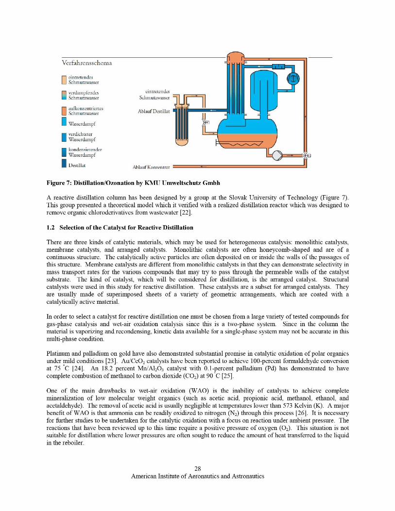
There have been concerns raised that when human urine is used as a fertilizer in agriculture certain pharmaceuticalsare transferred to and pollute groundwater. In the interest of destroying these pharmaceuticals in urine ozonationhas been sought as a pretreatment step to the use of urine as a fertilizer [20]. In particular, KMU Umweltschutzgmbh has developed an evaporator which includes ozonation for the purification of wastewater [21]. It has beendemonstrated that this device will remove pharmaceutical compounds from wastewater.
27American Institute of Aeronautics and Astronautics
Verfahrensschedna
ntretendesZhmurzwasser
verdampfendes eintretendesSchniutzwasser Schmurnvasser
adkonzentriertesAblautDestillatSchniuumasser
Wasserdampf
verdichteterWasserdampf
kondensierenderWasserdampf
Destillat AblaufKonzentrat
Figure 7: Distillation/Ozonation by KMU Umweltschutz Gmbh
A reactive distillation column has been designed by a group at the Slovak University of Technology (Figure 7).This group presented a theoretical model which it verified with a realized distillation reactor which was designed toremove organic chloroderivatives from wastewater [22].
1.2 Selection of the Catalyst for Reactive Distillation
There are three kinds of catalytic materials, which may be used for heterogeneous catalysis: monolithic catalysts,membrane catalysts, and arranged catalysts. Monolithic catalysts are often honeycomb-shaped and are of acontinuous structure. The catalytically active particles are often deposited on or inside the walls of the passages ofthis structure. Membrane catalysts are different from monolithic catalysts in that they can demonstrate selectivity inmass transport rates for the various compounds that may try to pass through the permeable walls of the catalystsubstrate. The kind of catalyst, which will be considered for distillation, is the arranged catalyst. Structuralcatalysts were used in this study for reactive distillation. These catalysts are a subset for arranged catalysts. Theyare usually made of superimposed sheets of a variety of geometric arrangements, which are coated with acatalytically active material.
In order to select a catalyst for reactive distillation one must be chosen from a large variety of tested compounds forgas-phase catalysis and wet-air oxidation catalysis since this is a two-phase system. Since in the column thematerial is vaporizing and recondensing ; kinetic data available for a single-phase system may not be accurate in thismulti-phase condition.
Platinum and palladium on gold have also demonstrated substantial promise in catalytic oxidation of polar organicsunder mild conditions [23]. Au/CeO2 catalysts have been reported to achieve 100-percent formaldehyde conversionat 7.5 C [24]. An 18.2 percent Mn.%Al2O3 catalyst with 0.1-percent palladium (Pd) has demonstrated to havecomplete combustion of methanol to carbon dioxide (CO 2) at 90 'C [25].
One of the main drawbacks to wet-air oxidation (WAO) is the inability of catalysts to achieve completemineralization of low molecular weight organics (such as acetic acid, propionic acid, methanol, ethanol, andacetaldehyde). The removal of acetic acid is usually negligible at temperatures lower than 573 Kelvin (K). A majorbenefit of WAO is that ammonia can be readily oxidized to nitrogen (N 2) through this process [26]. It is necessaryfor further studies to be undertaken for the catalytic oxidation with a focus on reaction under ambient pressure. Thereactions that have been reviewed up to this time require a positive pressure of oxygen (0 2). This situation is notsuitable for distillation where lower pressures are often sought to reduce the amount of heat transferred to the liquidin the reboiler.
28American Institute of Aeronautics and Astronautics
New catalysts have been tested for the treatment of wastewater. One area of heterogeneous catalysis is dedicated tothe destruction of halogenated organic compounds (HOCs). In this way, wastewater is detoxified by Pd onnanoscale supports, which catalyze the hydrodehalogenation of HOCs. Nanoscale supports previously used includegold, zero-valent iron, or magnetite [27] [28].
At this time the best catalyst for use in the reactive distillation column for wastewater purification may be theAu/CeO2 catalyst reported to achieve 100-percent formaldehyde conversion at 75 *C [29]. If this catalyst isincorporated into the distillation column, it needs to be tested for oxidation of a variety of other volatile organiccompounds (VOCs). The durability, kinetics, and lifetime of the catalyst would also need to be deternvned. Alongthese lines, I contacted KMU Umweltschutz about the possibility of developing a packing material (e.g. Raschigrings) impregnated with a nanogold catalyst. They were interested in the concept and referred me to a colleague oftheirs in Leipzig for further discussions.
Thermal catalytic oxidation is preferable to photocatalytic oxidation so long as the catalyst achieved completeoxidation of polar organics at 100 'C or below. Photocatalytic oxidation requires an additional power source tooperate an external light source. The design of the column with regards to the placement of the bulbs and theintegration of the cooling water would also be a concern for the photocatalytic system. Additionally, the coolingwater would have an additional heat load from the ultraviolet (UV) light. Since catalysts have been reported to beactive for methanol mineralization below 100 ^C, the simplest solution is to use a thermally-activated catalyst.
IV. Conclusion
Air stripping is useful for the removal of annnonia and some of the volatile organics, which are not removed by thedistillation process. This process requires relatively low power to remove components from water. Acoimnercially-available unit was found, which would require 500 W to process 5.4 L of wastewater in one hour.
The scaling of these purification systems for the lunar gravitational environment is taken into account. Previousanalysis of this particular problem reveals that scaling factors can be applied to the diameter of the columns toachieve the same purity levels that are achieved on earth. It will also be necessary to assess the role a low gravityenvironment would play in the physics of the water/air nuxture (froth) and also containment and flow. Studies incomputational fluid dynamics may shed additional li ght on this process for a more precise scaling factor fordistillation columns and air strippers operating on the lunar surface.
The processing rate for the processes modeling in this report has been set to be 20 L/day. It may be of interest todetermine the optimum processing time for a system architecture of an air stripper, fractional distillation colurrui,catalytic oxidizer, and a CO, removal bed. In this way, the total processing time can be optinuzed with respect tothe required blower power, heating requirements, and cooling requirements. A study comparing the benefits of thecomplete water recovery system with air stripping as compared to steam stripping may also potentially be ofinterest.
References
[1] Trachtenberg, M.C.: Bao, L.: Goldman, S.L.: Smith, D.A. "Dynamic Maintenance of CO 2 Levels in ClosedEnvironments" ICES 2004-01-2376.
[2] Saxena, P., and L.M. Hildemann (1996). Water-Soluble Organics in Atmospheric Particles: A Critical Review ofthe Literature and Application of Therniodynamics to Identify Candidate Compounds. Journal of AtmosphericChemistry 24:59-109.
[3] (a) Mullen, W.; Kranz, V.: Schroeder, R.; O'Brien, P.J., Design of a Steam Stripper / Distillation Process toTreat Pharmaceutical Wastewater, 8 `1' Annual Industrial Wastes Technical and Regulatory Conference — August 1I-
29American Institute of Aeronautics and Astronautics
14, 2002- (b) Wijmans, J.G.: Kamaruddin ; H.D.: Segelke, S.V.; Wessling, M.; Baker, R.W. "Removal of DissolvedVOCs from Water with an Air Stripper/Membrane Vapor Separation System" Separation Science and Technology,32, 14, 2267-2287, 1997- (c) Ortiz-Del Castillo, J.R.; Guerrero-Medina, G.; Lopez-Toledo, J.; Rocha, J.A. "Designof Steam-Stripping Columns for Removal of Volatile Organic Compounds from Water Using Random andStructural Packings" 39, 731-739, 2000- (d) Hwang, Y.-L.; Keller, G.E.; Olson, J.D. "Steam Strippin g for Removalof Organic Pollutants from Water. 1. Stripping Effectiveness and Stripper Design" 31, 1753-1759, 1992- (e) Hwang,Y.-L. Olson, J.D.; Keller, G.E. "Steam Strippin g for Removal of Organic Pollutants from Water. 2. Vapor-LiquidEquilibrium Data" 31, 1759-1768, 1992- (f) Bomberger, D.C.; Marynowski, C.W. "Design of Steam-StrippingProcesses" Environmental Progresses 3, 4, 217-222, 1984.
[4] (a) Advanced Physiochemical Treatment Processes, Lawrence K. Man (Editor), Yang-Tse Hung (Editor), Na-ihK. Shammas(Editor), Huang, Ju-Chang: Shang, Chil Vol. 4, Chapter 2, 2006. (b) Kutzer, S., Wintrich, H. Mersmann"Air Stripping — A Method for Treatment of Wastewater" Chem. Eng. Technol. 18, 149-155, 1955. (c) Akiyama, Y.,Valsaraj, K.T.; Wetzel, D.M.; Harrison, D.P. "On the Performance of a Cascade Crossflow Air Stripping Column"Ind. Eng. Chem. Res. 35, 3597-3606, 1996. (d) W"mans, J.G.; Kamaruddin, H.D.; Segelke, S.V.; Wessling ; M.;Baker, R.W. "Removal of Dissolved VOCs from Water with an Air Stripper/Membrane Vapor Separation System"Separation Science and Technology 32, 14, 2267-2287, 1997. (e) Linek, V., Sinkule, J.; Janda, V. "Design ofPacked Aeration Towers to Strip Volatile Organic Contaminants from Water." Wat. Res. 32, 4, 1264-1270 7 1998. (f)Blackwell, B.R.; Murray, F.E.; Oldham ; W.K. "Analysis of Simultaneous Heat and Mass Transfer in the Strippingof Methanol from Aqueous Solutions." Canadian Journal of Chemical Engineering 62, 845-856, 1984. (g) Ball,W.P. Jones, M.D.; Kavanaugh, M.C. "Mass Transfer of Volatile Organic Compounds in Packed Tower Aeration" J.Water Pollut. Contr. Federation 56. 2, 127-136, 1984.
[5] Mullen, Q.: Kranz, V.; Schroeder, R., O'Brien, P.J. "Design of a Steam Stripper/Distillation Process to TreatPharmaceutical Wastewater" 8th Annual Industrial Wastes Technical and Regulatory Conference 2002.
[6] Chao, K.-P.; Ong, S.K.; Huan g, M.-C. "Mass Transfer of VOCs in laboratory-scale air sparging tank" Journal ofHazardous Materials, 152, 1098-1107, 2008. (c) Reed, B.E.; Lin, W.; Matsumoto, M.R.: Jensen, J.N."Physicochemical Processes" 9-ater Environment Research 69, 4, 444-462, 1997.
[7] Shah, F.H.; Hadim, H.A.; Korfiatis, G.P. "Laboratory Studies of Air Stripping of VOC-Contaminated Soils,Journal of Soil Contamination, 4(1):93-109, 199.5.
[8] Ba^akgilardan-Kabakci, S.; Ipekoglu, A.N.; Ilhan, T. "Recovery of Arnrnonia from Human Urine by Strippingand Absorption" Environmental Engineering Science 24, 5, 2007, 615-624.
[9] Boul, P. "The Evaluation of Photocatalytic Oxidation and Thermal Catalytic Oxidation for a Trace ContaminantControl System" ESCG-4470-09-TEAN-DOC-0096, 2009.[10] Mullen. Q.; Kranz, V.; Schroeder, R.; O'Brien, P.J. "Design of a Steam Stripper/Distillation Process to TreatPharmaceutical Wastewater" 8th Annual Industrial Wastes Technical and Regulatory Conference 2002-
[11] (a) Huang. J.-C.; Shang, C. Advanced Physicochemical Processes Ed. Lawrence K. Wang, Yunb Tse Hung,Nazih K. Sharnmas, Vol. 4, Chapter 2, 2006- (b) Crittenden, J.C.; Trussell, R.R.: Hand, D.W.; Howe, K.J.:Tchobanoglous, G. Water Treatment Principles and Desi gn John Wiley & Sons, Inc. 2005.
[12] <http://www.cheresources.com/packcolzz.shtml>.
[13] (a) Perry and Green, Perry's Chemical Engineers Handbook, Sixth Edition, McGraw Hill, Inc. 1984. (b)Treybal, R.E. Mass Transfer Operations, McGraw Hill Inc., 1980. (c) Ball ; W. P., Jones, M. D., and Kavanaugh, M.C. "Mass Transfer of Volatile Organic Compounds in Packed Tower Aeration." Journal Water Polhrtion Control,56(2), 127-136 7 1984.
[14] (a) Pettit, D.R. "Fractional Distillation in a Lunar Environment." In Lunar Bases and Space Activities in the 21"Century, Lunar Planetary Institute (1985), 507-518. (b) Pettit, D.R.; Allen ; D.T. "Unit Operations for Gas-Liquid
30American Institute of Aeronautics and Astronautics
Mass Transfer in Reduced Gravity Environments." The Second Conference on Lunar Bases and Space Activities ofthe 21st Century, Vo1.2, 647-651, 1988.
[15] Pettit, D.R. "Performance of Absorption and Distillation Coluirms in a Lunar Environment." Chem. Engr.Commun., 46, 111-122, 1985.
[16] Tade, M.O.; Bisowarno, B.H.; Tian, Y.-C. "Modeling and Control of Reactive Distillation Systems."
[ 17] Sunmacher, Kai; Mariyana, I. "Moderne Trenn- and Reaktionstechniken: Die Reaktivdestillation" Chem.Unserer Zeit, 2003, 37, 268-278.
[18] Muhammad, A.-A., Luyben, W.L. "Comparison of Alternative Control Structures for an Ideal Two-ProductReactive Distillation Column- Ind. Eng. Chem. Res. 2000, 39, 3298-3307.
[19] Saha, B.: Chopade, S.P.: Mahajam, S.M. "Recovery of dilute acetic acid through esterification in a reactivedistillation column" Catalvsis Today 2000, 60, 147-157.
[20] (a) Gajurel, D.R.; Kucharek, K., Skwiot, R., Hamner, M.; Furmanska, M., Gulyas, H.: Otterpohl, R."Ozonisier uzg von Urin zur Entfernung von Pharmaka." Wasser Abwasser, 148, 4, 2007 (b) Tettenborn, F.:Behrendt, J., Otterpohl, R. "Exemplary Treatment Processes for Yellow Water - Nutrients and PharmaceuticalResidues" Science of the Total Environment, 399, 1-3, 96-104 ; 2008.
[21] European Patent Office, 06021670.2, 2007/16.
[22] Kotora, M., Markos, J.; Camaj, V. "Design of a reactive distillation column for ecological decomposition oforganic chloroderivatives in waste water" Chemical Engineering Sciences 62, 5193-5197, 2007.
[23] Bond, G.C. "The Electronic Structure of Platinum-Gold Alloy Particles" Platinum Metals Rev. 2007, 51, 2, 63-68.
[24] Jun Zhang, Ying Jin, Changyan Li, Yuenian Shen, Li Han, Zhongxue Hu, Xiaowei Di, Zhiliang Liu "Creationof three-dimensionally ordered macroporous Au/CeO, catalysts with controlled pore sizes and their enhancedcatalytic performance for formaldehyde oxidation" Applied Catalysis B: Environmental, 2009, 91, 1-2, 11-20.
[25] Alvarez-Galvin, M.C.: Pawelec, B.: de la Pena O'Shea, V.A.; Fierro, J.L.G.; Arias, P.L."Formaldehyde/methanol combustion on alumina-supported manganese-palladium oxide catalyst" 2004, 51, 83-91.
[26] Levec, J.: Pintar, A. "Catalytic wet-air oxidation processes: A review" 2007, 124, 172-184.
[27] Hildebrand, H.: Mackenzie, K.: Kopinke, F.-D. "Novel Nano-catalysts for Wastewater Treatment" 10, 1, 47-53,2008-
[28] Wong, M.S.: Alvarez, P.J.J.: Fang, Y.-L: Akin, N.: Nutt, M.O.: Miller, J.T.: Heck, K.N. "Cleaner water usingbimetallic nanoparticle catalysts" 2008, 84, 158-66.
[29] Jun Zhang, Ying Jin, Changyan Li, Yuenian Shen, Li Han, Zhongxue Hu, Xiaowei Di, Zhiliang Liu "Creationof three-dimensionally ordered macroporous Au/CeO 2 catalysts with controlled pore sizes and their enhancedcatalytic performance for formaldehyde oxidation" Applied Catalysis B: Environmental, 2009, 91, 1-2 7 11-20.
31American Institute of Aeronautics and Astronautics