Embed Size (px)
Citation preview

5.aSMC NO RT H AM E R I C A
AI R PR E PA R AT I O N PR O D U C T S
AI R PR E PA R AT I O N PR O D U C T S
SE R I E S PA G E NU M B E R
(N)AC1000-6000 5.1FRL CO M B I N AT I O N UN I T S - MO D U L A R TY P E
(N)AC1010-4010 5.2FRL CO M B I N AT I O N UN I T S - MO D U L A R TY P E
(N)AF 5.3AI R F I LT E R
(N)AR 5.4AI R RE G U L AT O R
(N)AL 5.6AI R LU B R I C AT O R
(N)AW 5.7AI R F I LT E R -RE G U L AT O R CO M B I N AT I O N UN I T - MO D U L A R TY P E
(N)AFM 5.9MI S T SE PA R AT O R
(N)AFD 5.10MI C R O-MI S T SE PA R AT O R
(N)AV2000/3000/4000 5.11SO F T STA RT-UP VA LV E
IS1000 5.13PR E S S U R E SW I T C H
Courtesy of Steven Engineering, Inc. ! 230 Ryan Way, South San Francisco, CA 94080-6370 ! Main Office: (650) 588-9200 ! Outside Local Area: (800) 258-9200 ! www.stevenengineering.com

5.b SMC NO RT H AM E R I C A
AI R PR E PA R AT I O N PR O D U C T S
SE R I E S PA G E NU M B E R
(N)VHS 5.14SH U T-OF F VA LV E - 3 PO RT RE L I E V I N G
Y - SPA C E R 5.15APP AC C E S S O R I E S - MO D U L A R TY P E
L TY P E BR A C K E T / T TY P E BR A C K E T 5.15APP AC C E S S O R I E S - MO D U L A R TY P E
E - EN D BL O C K AD A P T O R 5.16APP AC C E S S O R I E S - MO D U L A R TY P E
(N)AKM 5.16CH E C K VA LV E
T TA K E-OF F / X TA K E-OF F 5.17BR A N C H I N G UN I T S
(N)AF 5.18HI G H FL O W AI R F I LT E R
(N)AM 5.19HI G H EF F I C I E N C Y MI S T SE PA R AT O R
(N)AMD 5.20HI G H EF F I C I E N C Y MI C R O-MI S T SE PA R AT O R
(N)AMF 5.21HI G H EF F I C I E N C Y OD O R RE M O VA L F I LT E R
AMG 5.22WAT E R SE PA R AT O R
Courtesy of Steven Engineering, Inc. ! 230 Ryan Way, South San Francisco, CA 94080-6370 ! Main Office: (650) 588-9200 ! Outside Local Area: (800) 258-9200 ! www.stevenengineering.com
5.cSMC NO RT H AM E R I C A
AI R PR E PA R AT I O N PR O D U C T S
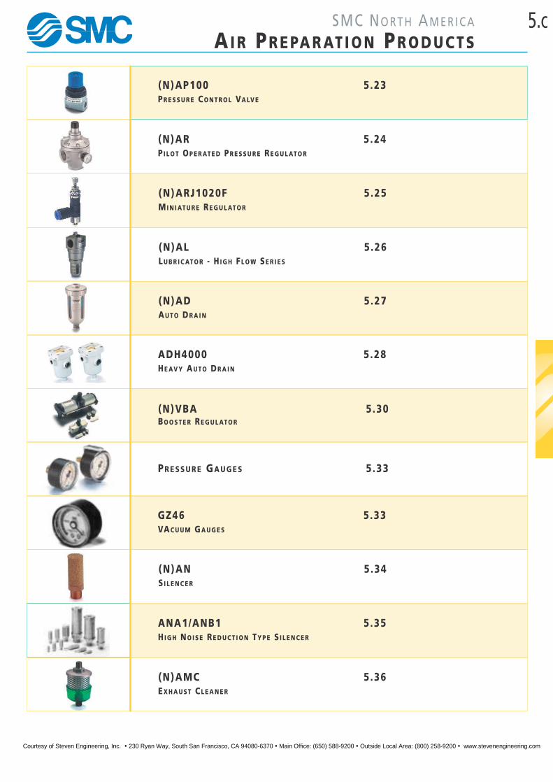
(N)AP100 5.23PR E S S U R E CO N T R O L VA LV E
(N)AR 5.24PI L O T OP E R AT E D PR E S S U R E RE G U L AT O R
(N)ARJ1020F 5.25MI N I AT U R E RE G U L AT O R
(N)AL 5.26LU B R I C AT O R - H I G H FL O W SE R I E S
(N)AD 5.27AU T O DR A I N
ADH4000 5.28HE AV Y AU T O DR A I N
(N)VBA 5.30BO O S T E R RE G U L AT O R
PR E S S U R E GA U G E S 5.33
GZ46 5.33VAC U U M GA U G E S
(N)AN 5.34SI L E N C E R
ANA1/ANB1 5.35HI G H NO I S E RE D U C T I O N TY P E S I L E N C E R
(N)AMC 5.36EX H A U S T CL E A N E R
Courtesy of Steven Engineering, Inc. ! 230 Ryan Way, South San Francisco, CA 94080-6370 ! Main Office: (650) 588-9200 ! Outside Local Area: (800) 258-9200 ! www.stevenengineering.com

5.d SMC NO RT H AM E R I C A
AI R PR E PA R AT I O N PR O D U C T S
Some of the Materials that wil l Attack Polycarbonate Plastic Bowls
Acetaldehyde Cresol Milk of l ime (CaOH)
Acetic acid Cyclohexanol Nitric acid
Acetone Cyclohexanone Nitrobenzene
Acrylonitri le Cyclohexene Nitrocellulose lacquer
Caustic soda solution Methanol Perchlorethylene and others
Ammonia Dimethyl formamide Phenol
Ammonium fluoride Dioxane Phosphorous Hydroxychloride
Ammonium hydroxide Ethane tetrachloride Phosphorous Trichloride
Ammonium sulphide Ethyl acetate Propionic acid
Antifreeze Ethyl ether Pyridine
Benzene Ethylamine Sodium hydroxide
Benzoic acid Ethlene chlorohydrin Sodium sulphide
Benzyl alcohol Ethlene dichloride Styrene
Bromobenzene Formic acid Sulphural chloride
Brake fluids Ethlene glycol Sulphuric acid
Butyric acid Freon (refrigerant & propellant) Tetrahydronaphthalene
Carbolic acid Gasoline Thiophene
Carbon disulphide Hydrazine Toluene
Carbon tetrachloride Hydrochloric acid Turpentine
Caustic potash solution Lacquer thinner Xylene
Chlorobenzene Methylene chloride
Chloroform Methylene sal icylate
SAFETYCompressed Air
1. Polycarbonate Bowls can be attacked by a wide variety of chemicals (see List
below for examples). These cause embrittlement and subsequent brittle failure,
or softening. Metal Bowls should be specified for use in the presence of
aggressive chemicals.
2. It is strongly recommended that metal bowl guards are specified to provide
additional protection from mechanical damage to polycarbonate bowls.
3. Before air treatment units are commissioned, and after any adjustment or
maintenance has been carries out, the following points should be checked before
connection to air supplies.
- All fittings and spacers are finally attached
- All removable bowls are securely screwed/latched into position
4. Polycarbonate bowls should be regularly inspected.
Courtesy of Steven Engineering, Inc. ! 230 Ryan Way, South San Francisco, CA 94080-6370 ! Main Office: (650) 588-9200 ! Outside Local Area: (800) 258-9200 ! www.stevenengineering.com

5.1F.R.L . CO M B I N AT I O N UN I T S
FOR FURTHER TECHNICALDETAILS ON THISPRODUCT, REQUESTCATALOG REFERENCEE5G, N5-G1 & N5-G3
S E E I N S I D E F R O N T C O V E R F O R
DETAILS OF YOUR LOCAL SALES OFFICE
MO D U L A R TY P E(N)AC1000–(N)AC6000 M5–1"
C o m b i n a t i o n o f f i l t e r, r e g u l a t o r a n d l u b r i c a t o r i n c l u d i n gmoun t i ng b r a cke t and p re s su re gauge
T E C H N I C A L
SPECIFICATIONS
S Y M B O L S
D I M E N S I O N S
N A C 1 0 0 0 , 2 0 0 0
H O W T O
O R D E R
FILTER/REGULATOR/LUBRICATOR
(N)AC 00 G
B O D Y S I Z E10 …M520 … 1⁄8 1⁄430 … 3⁄840 … 1⁄250 … 3⁄460 …1
D R A I N- ……Manua l d r a i nD ……Auto d r a i n
P O R T S I Z EM5 …M5X0 .801 … 1⁄802 … 1⁄403 … 3⁄804 … 1⁄206 … 3⁄410 …1
*Conditions: Supply pressure—7 Bar. Setting pressure—5 Bar Flow quoted at 1 bar pressure drop
Model Port size A B C D E F G H
With auto drain
J K L M N PFloat type Differential
pressure typeN.O.
B B
NAC1000 M5X0.8 91 84.5 25.5 25 26 25 33 20 4.5 7.5 5 17.5 16 38.5 — 86.5
NAC2000 1⁄8 1⁄4 140 125 38 40 56.8 30 50 24 5.5 8.5 5 22 23 50 — 120.5
NAC3000 3⁄8 181 156.5 38 53 60.8 41 64 35 7 11 7 34.2 26 70.5 182 —
NAC4000 1⁄2 238 191.5 41 70 65.5 50 84 40 9 13 7 42.2 33 88 217 —
NAC5000 3⁄4 300 271.5 48 90 75.5 70 105 50 12 16 10 55.2 40 115 297 —
NAC6000 1 315 285.5 48 95 78 70 110 50 12 16 10 55.2 40 117.5 311
D I M E N S I O N S
N A C 3 0 0 0 , 4 0 0 0 , 5 0 0 0 , 6 0 0 0
Model NAC1000 NAC2000 NAC3000 NAC4000 NAC5000 NAC6000
Combination
Air fi lter NAF1000 NAF2000 NAF3000 NAF4000 NAF5000 NAF6000
Regulator NAR1000 NAR2000 NAR3000 NAR4000 NAR5000 NAR6000
Lubricator NAL1000 NAL2000 NAL3000 NAL4000 NAL5000 NAL6000
Port Size M5X0.8 1⁄8, 1⁄4 3⁄8 1⁄2 3⁄4 1
Port Size for pressure gauge 1⁄161⁄8 1⁄8 1⁄4 1⁄4 1⁄4
Max Supply Pressure 15 Bar / 220PSI
Max Operating Pressure 9.9 Bar / 145PSI
Regulating Range 0.5~7 Bar 0.5 ~ 8.5 Bar / 8~125PSI
Max flow rate ln/min* 90 500 2000 4000 5000 7000
Min. operating conditions for autodrain 1 Bar / 14.5 PSI
Filtration Standard: 5µm
Recommended oil Turbin oil ISO VG32
Bowl material Polycarbonate
Construction/Regulator Relieving type
Accessories (standard) — — • • • •Bowl guard
Ambient and media temperature 5 ~ 60ºC / 40~140ºF
—
FOR MORE TECHNICAL INFORMATION
ON THIS SERIES, PLEASE REFER TO
CAT:E5G, N5-G1 & N5-G3
0.5 ~ 7 Bar / 8 ~100PSI
P O R T T H R E A D- ……Rc ( PT )* Remove (N ) when o rde r i ngN ……NPT*F ………G(PF )* Remove (N ) when o rde r i ng
Note)0.5 Bar = 0.05MPa7 Bar = 0.7MPa8.5 Bar = 0.85MPa
- ……Japane seN ……Nor th Ame r i c an
Courtesy of Steven Engineering, Inc. ! 230 Ryan Way, South San Francisco, CA 94080-6370 ! Main Office: (650) 588-9200 ! Outside Local Area: (800) 258-9200 ! www.stevenengineering.com
5.2 AI R PR E PA R AT I O N
F.R.L . CO M B I N AT I O N UN I T S
FOR FURTHER TECHNICALDETAILS ON THISPRODUCT, REQUESTCATALOG REFERENCEE5G, N5-G1 & N5-G3
T E C H N I C A L
SPECIFICATIONS
S Y M B O L S
D I M E N S I O N S
N A C 1 0 1 0 , 2 0 1 0
D I M E N S I O N S
N A C 3 0 1 0 , 4 0 1 0
H O W T O
O R D E R
FILTER/REGULATOR, LUBRICATOR
(N)AC 10 G
B O D Y S I Z E10 …M520 … 1⁄8 1⁄430 … 3⁄840 … 1⁄2
D R A I N- ……Manua l D r a i nD ……Auto D ra i n
P O R T S I Z EM5 …M5X0 .801 … 1⁄802 … 1⁄403 … 3⁄804 … 1⁄2
*Conditions: Supply pressure—7 Bar. Setting pressure—5 Bar Flows quoted at 1 Bar pressure drop0.5~7 Bar = 8~100PSI
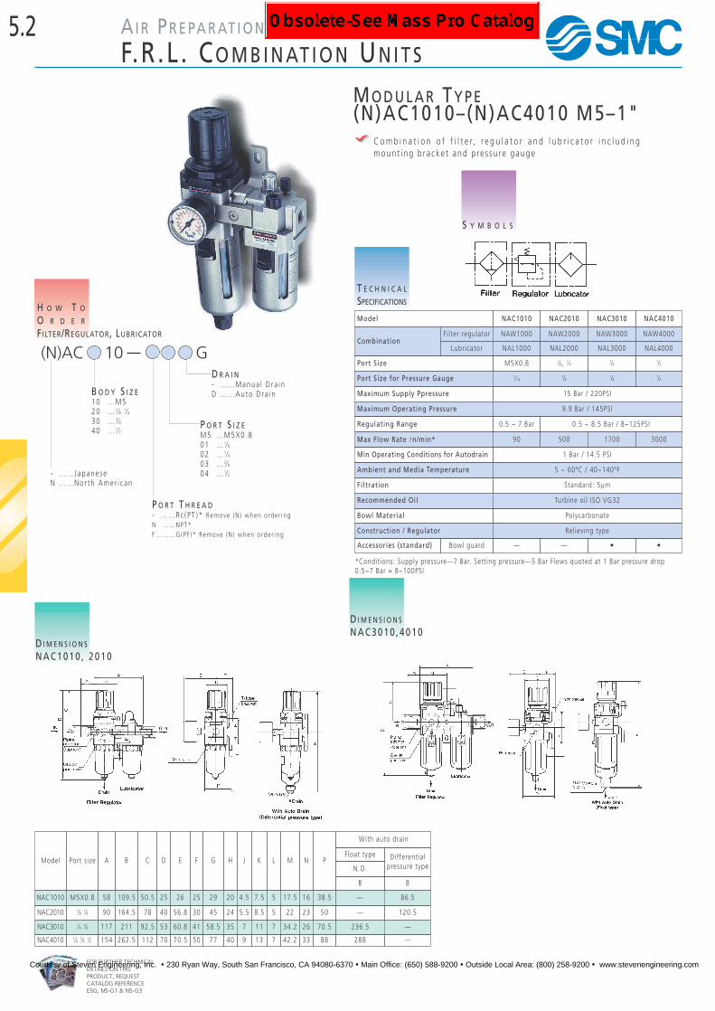
MO D U L A R TY P E(N)AC1010–(N)AC4010 M5–1"
C o m b i n a t i o n o f f i l t e r, r e g u l a t o r a n d l u b r i c a t o r i n c l u d i n gmoun t i ng b r a cke t and p re s su re gauge
Model
Ambient and Media Temperature
NAC1010 NAC2010 NAC3010 NAC4010
5 ~ 60ºC / 40~140ºF
CombinationFi lter regulator NAW1000 NAW2000 NAW3000 NAW4000
Lubricator NAL1000 NAL2000 NAL3000 NAL4000
Port Size M5X0.8 1⁄8, 1⁄4 3⁄8 1⁄2
Port Size for Pressure Gauge 1⁄161⁄8 1⁄8 1⁄4
Maximum Supply Ppressure 15 Bar / 220PSI
Maximum Operating Pressure 9.9 Bar / 145PSI
Regulating Range 0.5 ~ 7 Bar 0.5 ~ 8.5 Bar / 8~125PSI
Max Flow Rate ln/min* 90 500 1700 3000
Min Operating Conditions for Autodrain 1 Bar / 14.5 PSI
Filtration Standard: 5µm
Recommended Oil Turbine oil ISO VG32
Bowl Material Polycarbonate
Construction / Regulator Relieving type
Accessories (standard) Bowl guard — — • •
Model Port size A B C D E F G H J K L M N P
With auto drain
Float type Differential pressure typeN.O.
B B
NAC1010 M5X0.8 58 109.5 50.5 25 26 25 29 20 4.5 7.5 5 17.5 16 38.5 — 86.5
NAC2010 1⁄8 1⁄4 90 164.5 78 40 56.8 30 45 24 5.5 8.5 5 22 23 50 — 120.5
NAC3010 1⁄4 3⁄8 117 211 92.5 53 60.8 41 58.5 35 7 11 7 34.2 26 70.5 236.5 —
NAC4010 1⁄4 3⁄8 1⁄2 154 262.5 112 70 70.5 50 77 40 9 13 7 42.2 33 88 288 —
P O R T T H R E A D- ……Rc ( PT )* Remove (N ) when o rde r i ngN ……NPT*F ………G(PF )* Remove (N ) when o rde r i ng
- ……Japane seN ……Nor th Ame r i c an
Courtesy of Steven Engineering, Inc. ! 230 Ryan Way, South San Francisco, CA 94080-6370 ! Main Office: (650) 588-9200 ! Outside Local Area: (800) 258-9200 ! www.stevenengineering.com

5.3
FOR FURTHER TECHNICALDETAILS ON THISPRODUCT REQUESTCATALOG REFERENCEE5G, N5-G1 & N5-G3
A I R PR E PA R AT I O N
MO D U L A R TY P E
S E E I N S I D E F R O N T C O V E R F O R
DETAILS OF YOUR LOCAL SALES OFFICE
A I R F I LT E R SE R I E S (N)AFPo r t S i z e M5 – 1”Au tod ra i n a va i l ab l eNew supe r e f f i c i en t 5µm Po l y - e l emen tQu i c k re l e a s e bow l gua rd on some s i z e sH igh f l ow
(N)AF
1000 M52000 1⁄8• 1⁄43000 1⁄4• 3⁄84000 3⁄8• 1⁄25000 3⁄4•16000 1
B O D Y S I Z E
M5 …M501 … 1⁄802 … 1⁄403 … 3⁄804 … 1⁄206 … 3⁄410 …1
P O R T S I Z E
- ……W i thou tD ……W/Auto D ra i nB ……Bracke t
A C C E S S O R I E S
H O W T O
O R D E R
A I R F I L T E R
S Y M B O L S
D I M E N S I O N S
N A F 1 0 0 0 • 2 0 0 0
D I M E N S I O N S
N A F 3 0 0 0 • 4 0 0 0
D I M E N S I O N S
N A F 5 0 0 0 • 6 0 0 0
A B D E F G H J K L M P
NAF1000 25 66 7 25 - - - - - - - - 26.5 86.5 Differential pressure
NAF2000 40 97.5 11 40 17 30 27 22 5.4 8.4 40 2.3 40 120.5 Differential pressure
NAF3000 53 132.5 14 53 16 41 40 23 6.5 8 53 2.3 56 158 Float
NAF4000 70 168.5 18 70 17 50 54 26 8.5 10.5 70 2.3 73 194 Float
NAF5000 90 247.5 24 90 23 70 66 35 11 13 90 3.2 90 273 Float
NAF6000 95 261.5 24 95 23 70 66 35 11 13 90 3.2 95 287 Float
B Type
With Auto Drain
T E C H N I C A L
SPECIFICATIONS
ACCESSORIES
A I R F I L T E R
Po l y F i l t e r S i n t e red B ronze App l i c ab l eE l emen t F i l t e r E l emen t 5µm F i l t e r S e r i e s111344 . . . . . . . . . 11134 -5B . . . . . . . . . . . . . . . . . . .NAF10001129116A . . . . . . 11294 -5B . . . . . . . . . . . . . . . . . . .NAF2000111585A . . . . . . . 111511 -5B . . . . . . . . . . . . . . . . . .NAF30001116103A . . . . . . 11104 -5B . . . . . . . . . . . . . . . . . . .NAF4000111724A . . . . . . . 11173 -5B . . . . . . . . . . . . . . . . . . .NAF5000111825A . . . . . . . 11074 -5B . . . . . . . . . . . . . . . . . . .NAF6000No te : Sintered bronze and Poly-elements are not interchangableB r a cke tB240 . . . . . . . . . . . .NAF2000B340 . . . . . . . . . . . .NAF3000B440 . . . . . . . . . . . .NAF4000B640 . . . . . . . . . . . .NAF5000 /6000
CModel
* 0.7MPa supply, Pressure drop �P = 0.05MPa* Flow data is for new Poly-Element
FOR MORE TECHNICAL INFORMATION
ON THIS SERIES, PLEASE REFER TO
CAT:E5G, N5-G1 & N5-G3
Port size M5x0.8 1⁄8 1⁄4 1⁄4 3⁄8 3⁄8 1⁄2 3⁄4 1 1
Max supply pressure
Min . ope r a t i ng cond i t i on f o r au tod ra i n t ype
Flow rate ln/min* 140 1050 2800 5000 7000
Minimum flow 100 nl/min
8000
1.5MPa / 220PSI
Max. operating pressure
Minimum Pressure 0.1MPa / 14.5 PSI
1MPa / 145PSI
Ambient and media temperature 5 ~ 60°C / 40~140ºF
Bowl capacity cm3 4 15 20 45 130 130
Bowl material Polycarbonate
Filtration Standard: 5µm
Model NAF1000 NAF2000 NAF3000 NAF4000 NAF5000 NAF6000
- ……Rc ( P T )* Remove (N ) when o rde r i ngN ……NPTF ……G(PF )* Remove (N ) when o rde r i ng
P O R T T H R E A D
- ……Japane seN ……Nor th Ame r i c an
Courtesy of Steven Engineering, Inc. ! 230 Ryan Way, South San Francisco, CA 94080-6370 ! Main Office: (650) 588-9200 ! Outside Local Area: (800) 258-9200 ! www.stevenengineering.com

0 ……W i th gauge po r t1 ……W i th Bu i l t - i n Gauge
(Ava i l ab l e f o r body s i z e s 20~40 on l y )
G A U G E
0 ……Re l i e v i ng6 ……W i th Check Va l v e
* Bu i l t - i n Gauge no ta va i l ab l e w i t h t h i s op t i on .S t anda rd on AR1000
B O D Y S I Z E
5.4
FOR FURTHER TECHNICALDETAILS ON THISPRODUCT REQUESTCATALOG REFERENCEE5G, N5-G1 & N5-G3
A I R PR E PA R AT I O N
MO D U L A R TY P E
RE G U L AT O R SE R I E S (N)ARPo r t S i z e M5 – 1””Q“ and ”P“ compensa t i onDes i gn i n c l ude s pane l moun t r i ngH igh f l owNon -modu l a r, h i ghe r f l ow and p re c i s i on t yperegu l a to r s a re a va i l ab l e ( s e e i ndex )Check v a l v e op t i on a va i l ab l eBu i l t i n gauge a va i l ab l e
(N)AR
10 …M520 … 1⁄8• 1⁄425 … 1⁄4• 3⁄830 … 1⁄4• 3⁄840 … 3⁄8• 1⁄2• 1⁄450 … 3⁄4•1”60 …1”
M5 …M501 … 1⁄802 … 1⁄403 … 3⁄804 … 1⁄206 … 3⁄410 …1”
P O R T S I Z E
- ……Standa rd1 ……Low p re s su re 0 . 2~2 Ba rR ……For r i gh t t o l e f t f l ow (w i t h Bu i l t - I n
Gauge Type on l y )M ……Meta l S ea l TypeN ……Non-Re l i e v i ng Type
R E G U L A T O R R A N G E
H O W T O
O R D E R
P R E S S U R E R E G U L A T O R
S Y M B O L S
ACCESSORIES
P R E S S U R E R E G U L A T O R
B ra cke tB120 ……………………………NAR1000B220 ……………………………NAR2000 /2500B320 ……………………………NAR3000B420 ……………………………NAR4000B540 ……………………………NAR5000B640 ……………………………NAR6000
T E C H N I C A L
SPECIFICATIONS
See P re s su re Gauge s Page
P R E S S U R E G A U G E S
Port Size M5x0.8 1⁄8 1⁄4 1⁄4 3⁄8 1⁄4 3⁄8 3⁄8 1⁄2 3⁄4 1 1
1⁄4
Flow Rate ln/min* 100 550 2000 2500 6000 8000 10000
1⁄4
Max Supply Pressure
Optional low pressure regulator range 0.02~0.2MPa / 3~30PSI
1.5MPa / 220PSI
Max Operating Pressure 1MPa / 145PSI
Pressure Regulating Range 0.05-0.7MPa 0.05~0.8MPa/ 8~125PSI (AR*000 ); see Note 1 below
Port Size for Pressure Gauge 1⁄161⁄8 1⁄8 1⁄8 1⁄4
Ambient and Media Temperature 5 ~ 60°C / 40~140ºF
Construction Relieving Type
Model NAR1000 NAR2000 NAR3000 NAR4000 NAR5000 NAR6000
* 0.7MPa supply, pressure = 0.5MPa, Pressure drop �P = 0.1MPa; Note 1) 14.4~125PSI (AR*060)
NAR2500
- ……W i thou tG ……Gauge fo r NAR**01 t ypeB ……Bracke t
Relieving type Check valvetype
FOR MORE TECHNICAL INFORMATION
ON THIS SERIES, PLEASE REFER TO
CAT:E5G, N5-G1 & N5-G3
FOR MORE TECHNICAL INFORMATION
ON THIS SERIES, PLEASE REFER TO
CAT:E5G, N5-G1 & N5-G3
- ……Rc ( PT )* Remove (N )when o rde r i ng
F … … PFN ……NPT* Remove (N )
when o rde r i ng
P O R T T H R E A D
A C C E S S O R I E S
- ……Japane seN ……Nor th Ame r i c an
Courtesy of Steven Engineering, Inc. ! 230 Ryan Way, South San Francisco, CA 94080-6370 ! Main Office: (650) 588-9200 ! Outside Local Area: (800) 258-9200 ! www.stevenengineering.com

5.5
FOR FURTHER TECHNICALDETAILS ON THISPRODUCT REQUESTCATALOG REFERENCEE5G, N5-G1 & N5-G3
A I R PR E PA R AT I O N
MO D U L A R TY P E
S E E I N S I D E F R O N T C O V E R F O R
DETAILS OF YOUR LOCAL SALES OFFICE
D I M E N S I O N S
N A R 1 0 0 0 ~ N A R 5 0 0 0D I M E N S I O N S
N A R 6 0 0 0
Model A B C D E F G H J K L M N
NAR1000 25 61.5 11 25 26 25 18 30 4.5 6.5 40 2 20.5
NAR2000 40 95 17 40 56.8 30 30 45 5.4 15.4 55 2.3 33.5
NAR2500 53 102.5 25 48 60.8 30 34 44 5.4 15.4 55 2.3 33.5
NAR3000 53 127.5 35 53 60.8 41 40 46 6.5 8 53 2.3 42.5
NAR4000 70 149.5 37.5 70 65.5 50 54 54 8.5 10 .5 70 2.3 52.5
NAR5000 90 168 48 90 75.5 70 66 65.8 11 13 90 3.2 52.5
NAR6000 95 204.5 48 95 78 70 66 65.8 11 13 90 3.2 -
D I M E N S I O N S
N A R 2 0 0 1 ~ N A R 4 0 0 1
Model Part Size A B C D E Bracket Dimensions NF G H J K L M
NAR2001 1 /8 • 1 / 4 40 95 17 40 35 30 34 44 5 .4 15 .4 55 2 .3 33 .5NAR25O1 1 /4 • 3 / 8 53 102 .5 25 48 32 30 34 34 44 5 .4 15 .4 55 2 .3NAR3001 1 /4 • 3 / 8 53 127 .5 35 53 29 .5 41 40 46 6 .5 8 53 2 .3 42 .5NAR4001 1 /4 • 3 / 8 • 1 / 2 70 149 .5 37 .5 70 38 50 54 54 8 .5 10 .5 70 2 .3 52 .5
Bracket
Port Size
Courtesy of Steven Engineering, Inc. ! 230 Ryan Way, South San Francisco, CA 94080-6370 ! Main Office: (650) 588-9200 ! Outside Local Area: (800) 258-9200 ! www.stevenengineering.com

5.6
FOR FURTHER TECHNICALDETAILS ON THISPRODUCT REQUESTCATALOG REFERENCEE5G, N5-G1 & N5-G3
A I R PR E PA R AT I O N
MO D U L A R TY P E
LU B R I C AT O R SE R I E S (N)ALPo r t S i z e M5 – 1”P re c i s e ad j u s tmen tUn i f o rm l ub r i c a t i on e ven a t e x t reme l y l ow f l ow r a t e sOve r 97% o f a tom i zed o i l p a r t i c l e s <10 m i c ron sQu i c k re l e a s e bow l gua rd on some s i z e s
(N)AL
1000 M52000 1⁄8• 1⁄43000 1⁄4• 3⁄84000 3⁄8• 1⁄25000 3⁄4•16000 1
B O D Y S I Z E
M5 …M501 … 1⁄802 … 1⁄403 … 3⁄804 … 1⁄206 … 3⁄410 …1
P O R T S I Z E
H O W T O
O R D E R
L U B R I C A T O R
S Y M B O L S
ACCESSORIES
L U B R I C A T O R
B ra cke tB240 ……………………………AL2000B340 ……………………………AL3000B440 ……………………………AL4000B640 ……………………………AL5000 /6000
D I M E N S I O N S
N A L 1 0 0 0 • N A L 2 0 0 0D I M E N S I O N S
N A L 3 0 0 0 • N A L 4 0 0 0D I M E N S I O N S
N A L 5 0 0 0 • N A L 6 0 0 0
T E C H N I C A L
SPECIFICATIONS
Model A B C D F G H J K L M P
NAL1000 25 81.5 25.5 25 - - - - - - - 27
NAL2000 40 122 38 40 30 27 22 5.4 8.4 40 2.3 40
NAL3000 53 142 38 53 41 40 23 6.5 8 53 2.3 56
NAL4000 70 177 41 70 50 54 26 8.5 10.5 70 2.3 73
NAL5000 90 254 45 90 70 66 35 11 13 90 3.2 90
NAL6000 95 268 45 95 70 66 35 11 13 90 3.2 95
FOR MORE TECHNICAL INFORMATION
ON THIS SERIES, PLEASE REFER TO
CAT:E5G, N5-G1 & N5-G3
Model NAL1000 NAL2000 NAL3000 NAL4000 NAL5000 NAL6000
Port size M5x0.8 1⁄8 1⁄4 1⁄4 3⁄8 3⁄8 1⁄2 3⁄4 1 1
Flow Rate ln/min 95 800 1700 5000 7000 7500
Max Supply Pressure 1.5MPa / 220PSI
Max Operating Pressure 1MPa / 145PSI
Min Operating Flow ln/min* 4 151⁄4: 303⁄8: 40
3⁄8: 401⁄2: 50
190 220
Bowl Capacity cm3 7 25 50 130 130 130
Recommended Oil ISO VG32
Ambient and Media Temperature 5 ~ 60°C / 40~140ºF
Bowl Material Polycarbonate
Accessory (Standard) Bowl Guard - - • • • •
*Conditions: Supply pressure - 0.5MPa Number of DROPS - 5 drops/min ISOVG32, 20°CMax Flow Data @0.5Mpa Supply 0.03MPa Pressure Drop
- ……Rc (PT )* Remove (N ) when o rde r i ngF … … PFN ……NPT* Remove (N ) when o rde r i ng
P O R T T H R E A D
- ……W/O B r a cke tB ……W i th B r a cke t
A C C E S S O R I E S
Re fe r t o CAT: E5G
O P T I O N A L S P E C S- ……Japane seN ……Nor th Ame r i c an
Courtesy of Steven Engineering, Inc. ! 230 Ryan Way, South San Francisco, CA 94080-6370 ! Main Office: (650) 588-9200 ! Outside Local Area: (800) 258-9200 ! www.stevenengineering.com
0 ……Standa rd1 ……W i th Bu i l t - i n Gauge 2 ……W i th Bu i l t - i n Gauge
fo r r i gh t t o l e f t f l ow(1 & 2 a va i l ab l e f o r bodys i z e s 20~40 on l y )
0
5.7
FOR FURTHER TECHNICALDETAILS ON THISPRODUCT REQUESTCATALOG REFERENCEE5G, N5-G1 & N5-G3
A I R PR E PA R AT I O N
MO D U L A R TY P E
S E E I N S I D E F R O N T C O V E R F O R
DETAILS OF YOUR LOCAL SALES OFFICE
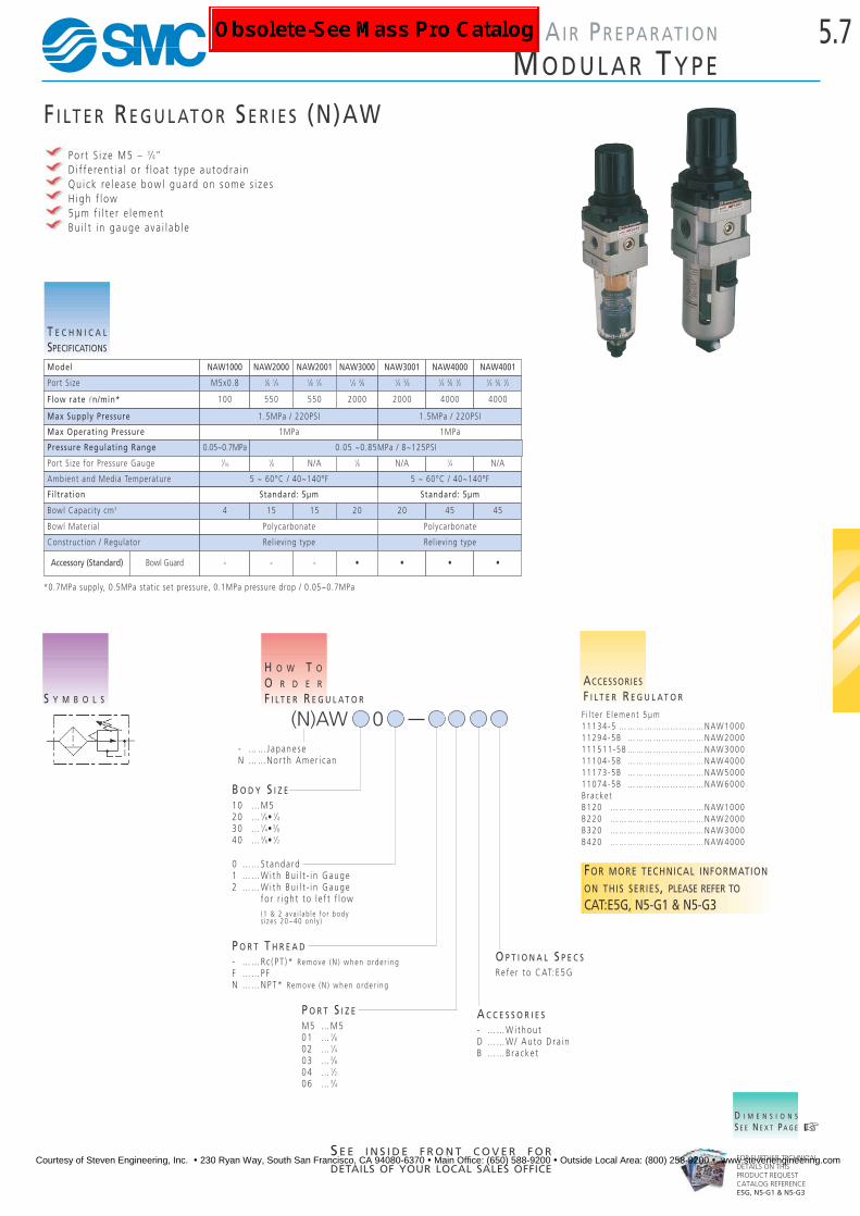
F I LT E R RE G U L AT O R SE R I E S (N)AWPo r t S i z e M5 – 3⁄4”D i f f e ren t i a l o r f l o a t t ype au tod ra i nQu i c k re l e a s e bow l gua rd on some s i z e sH igh f l ow5µm f i l t e r e l emen tBu i l t i n gauge a va i l ab l e
S Y M B O L S
ACCESSORIES
F I L T E R R E G U L A T O R
F i l t e r E l emen t 5µm11134 -5 …………………………NAW100011294 -5B ………………………NAW2000111511 -5B ………………………NAW300011104 -5B ………………………NAW400011173 -5B ………………………NAW500011074 -5B ………………………NAW6000B ra cke tB120 ……………………………NAW1000B220 ……………………………NAW2000B320 ……………………………NAW3000B420 ……………………………NAW4000
(N)AW
10 …M520 … 1⁄8• 1⁄430 … 1⁄4• 3⁄840 … 3⁄8• 1⁄2
B O D Y S I Z E
M5 …M501 … 1⁄802 … 1⁄403 … 3⁄804 … 1⁄206 … 3⁄4
P O R T S I Z E
- ……W i thou tD ……W/ Au to D ra i nB ……Bracke t
A C C E S S O R I E S
H O W T O
O R D E R
F I L T E R R E G U L A T O R
T E C H N I C A L
SPECIFICATIONS
*0.7MPa supply, 0.5MPa static set pressure, 0.1MPa pressure drop / 0.05~0.7MPa
FOR MORE TECHNICAL INFORMATION
ON THIS SERIES, PLEASE REFER TO
CAT:E5G, N5-G1 & N5-G3
Model NAW3001NAW1000 NAW2000 NAW2001 NAW3000 NAW4000
Port Size M5x0.8 1⁄8 1⁄4 1⁄8 1⁄4 1⁄4 3⁄8
NAW4001
Flow rate ln/min* 100 550 550 2000
Max Supply Pressure
1⁄4 3⁄8 1⁄4 3⁄8 1⁄2 1⁄4 3⁄8 1⁄2
1.5MPa / 220PSI
Max Operating Pressure
2000 4000 4000
1MPa
Pressure Regulating Range 0.05~0.7MPa
1.5MPa / 220PSI
1MPa
0.05 ~0.85MPa / 8~125PSI
Port Size for Pressure Gauge 1⁄161⁄8 N/A 1⁄8
Ambient and Media Temperature
N/A 1⁄4 N/A
5 ~ 60°C / 40~140ºF
Filtration
5 ~ 60°C / 40~140ºF
Standard: 5µm
20
Standard: 5µm
45Bowl Capacity cm3 4 15 15 20 45
Bowl Material Polycarbonate
Relieving type
Polycarbonate
•
Construction / Regulator
• •
Relieving type
Accessory (Standard) Bowl Guard - - - •
D I M E N S I O N S
S E E N E X T P A G E ☞
- ……Rc ( PT )* Remove (N ) when o rde r i ngF … … PFN ……NPT* Remove (N ) when o rde r i ng
P O R T T H R E A D
Re fe r t o CAT: E5G
O P T I O N A L S P E C S
- ……Japane seN ……Nor th Ame r i c an
Courtesy of Steven Engineering, Inc. ! 230 Ryan Way, South San Francisco, CA 94080-6370 ! Main Office: (650) 588-9200 ! Outside Local Area: (800) 258-9200 ! www.stevenengineering.com

5.8
FOR FURTHER TECHNICALDETAILS ON THISPRODUCT REQUESTCATALOG REFERENCEE5G, N5-G1 & N5-G3
A I R PR E PA R AT I O N
MO D U L A R TY P E
Type
W i th au to d r a i n
H ØNMODEL A B C D E F G J K L M PB
NAW1000 25 109.5 50.5 25 26 25 28 30 4.5 6.5 40 2.0 20.5 28 86.5 Differential pressure
NAW2000 40 164.5 78 40 56.8 30 34 45 5.4 15.4 55 2.3 33.5 40 120.5 Differential pressure
NAW3000 53 211 92.5 53 60.8 41 40 46 6.5 8.0 53 2.3 42.5 56 236.5 Float
NAW4000 70 262.5 112 70 70.5 50 54 54 8.5 10.5 70 2.3 52.5 73 288 Float
D I M E N S I O N S
N AW 3 0 0 0 • 4 0 0 0D I M E N S I O N S
N AW 1 0 0 0 • 2 0 0 0
D I M E N S I O N S
N AW 3 0 0 1 - 4 0 0 1
PressureGauge
PortSize
Drain
Minimum spacerequired formaintenance
D I M E N S I O N S
N AW 2 0 0 1
B
L KG
JC
A
Drain
PressureGauge
Port Size
H
FM
E
S
D
P
Minimum space requiredfor maintenance
B
With auto drain(differential pressure type)
Type
W i th au to d r a i n
H ØNMODEL A B C D E F G J K L M PB
NAW2001 40 164.5 78 40 56.8 30 34 45 5.4 15.4 55 2.3 33.5 40 120.5 Differential pressure
NAW3001 53 211 92.5 53 60.8 41 40 46 6.5 8.0 53 2.3 42.5 56 236.5 Float
NAW4001 70 262.5 112 70 70.5 50 54 54 8.5 10.5 70 2.3 52.5 73 288 Float
Courtesy of Steven Engineering, Inc. ! 230 Ryan Way, South San Francisco, CA 94080-6370 ! Main Office: (650) 588-9200 ! Outside Local Area: (800) 258-9200 ! www.stevenengineering.com
5.9
FOR FURTHER TECHNICALDETAILS ON THISPRODUCT REQUESTCATALOG REFERENCEE5G, N5-G1 & N5-G3
A I R PR E PA R AT I O N
MO D U L A R TY P E
S E E I N S I D E F R O N T C O V E R F O R
DETAILS OF YOUR LOCAL SALES OFFICE
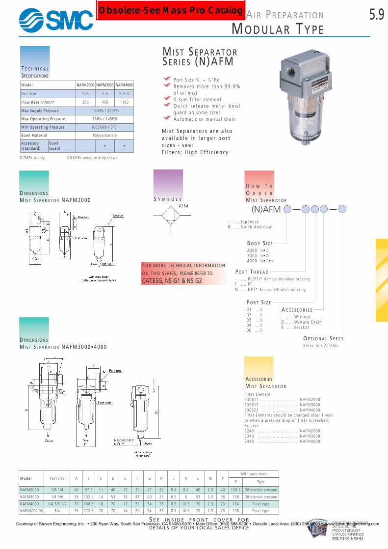
MI S T SE PA R AT O RSE R I E S (N)AFM
Po r t S i z e 1⁄8 – 3⁄4”RcR e m o v e s m o r e t h a n 9 9 . 9 %of o i l m i s t0 . 3µm f i l t e r e l emen tQ u i c k r e l e a s e m e t a l b o w lgua rd on some s i z e sAu toma t i c o r manua l d r a i n
(N)AFM
2000 1⁄8• 1⁄43000 1⁄4• 3⁄84000 3⁄8• 1⁄2• 3⁄4
B O D Y S I Z E
- ……Rc ( PT )* Remove (N ) when o rde r i ngF …… PFN ……NPT* Remove (N ) when o rde r i ng
P O R T T H R E A D
- ……W i thou tD ……W/Auto D ra i nB ……Bracke t
A C C E S S O R I E S
H O W T O
O R D E R
M I S T S E P A R A T O RS Y M B O L S
ACCESSORIES
M I S T S E P A R A T O R
F i l t e r E l emen t630611 …………………………NAFM2000630617 …………………………NAFM3000630623 …………………………NAFM4000F i l t e r E l emen t s s hou ld be changed a f t e r 1 y ea ro r when a p re s su re d rop o f 1 Ba r i s re a ched .B r a cke tB240 ……………………………NAFM2000B340 ……………………………NAFM3000B440 ……………………………NAFM4000
M i s t S e p a r a t o r s a r e a l s oa v a i l a b l e i n l a r g e r p o r ts i z e s - s e e :F i l t e r s : H i g h E f f i c i e n c y
Model AWith auto drain
1/8 1/4
Port size B C D E F G H J K L M PB Type
NAFM2000 40 97.5 11 40 17 30 27 22 5.4 8.4 40 2.3 40 120.5 Differential pressure
NAFM3000 1/4 3/6 53 132.5 14 53 16 41 40 23 6.5 8 53 2.3 56 158 Differential pressure
NAFM4000 1/4 3/8 1/2 70 168.5 18 70 17 50 54 26 8.5 10.5 70 2.3 73 194 Float type
NAFM4000-06 3/4 75 172.5 20 70 14 50 54 25 8.5 10.5 70 2.3 73 198 Float type
D I M E N S I O N S
M I S T S E P A R AT O R N A F M 2 0 0 0
D I M E N S I O N S
M I S T S E P A R AT O R N A F M 3 0 0 0 • 4 0 0 0
T E C H N I C A L
SPECIFICATIONS
0.7MPa supply, 0.01MPa pressure drop (new)
FOR MORE TECHNICAL INFORMATION
ON THIS SERIES, PLEASE REFER TO
CAT:E5G, N5-G1 & N5-G3
Model NAFM2000 NAFM3000 NAFM4000
Port Size 1⁄8 1⁄4 1⁄4 3⁄8 3⁄8 1⁄2 3⁄4
Flow Rate ln/min* 200 450 1100
Max Supply Pressure 1.5MPa / 220PSI
Max Operating Pressure 1MPa / 145PSI
Min Operating Pressure 0.05MPa / 8PSI
Bowl Material Polycarbonate
Accessory(Standard)
BowlGuard
- • •
01 … 1⁄802 … 1⁄403 … 3⁄804 … 1⁄206 … 3⁄4
P O R T S I Z E
Re fe r t o CAT: E5G
O P T I O N A L S P E C S
- ……Japane seN ……Nor th Ame r i c an
Courtesy of Steven Engineering, Inc. ! 230 Ryan Way, South San Francisco, CA 94080-6370 ! Main Office: (650) 588-9200 ! Outside Local Area: (800) 258-9200 ! www.stevenengineering.com

5.10
FOR FURTHER TECHNICALDETAILS ON THISPRODUCT REQUESTCATALOG REFERENCEE5G, N5-G1 & N5-G3
A I R PR E PA R AT I O N
MO D U L A R TY P E
MI C R O-MI S T SE PA R AT O RSE R I E S (N)AFD
Po r t S i z e 1⁄8 – 3⁄4 “Remove s mo re t han 99 .9999% o f o i l m i s t0 . 01µm f i l t e r e l emen tQuick release metal bowl guard on some sizesAu toma t i c o r manua l d r a i n
(N)AFD
2000 1⁄8• 1⁄43000 1⁄4• 3⁄84000 3⁄8• 1⁄2• 3⁄4
B O D Y S I Z E
M5 …M501 … 1⁄802 … 1⁄403 … 3⁄804 … 1⁄206 … 3⁄4
P O R T S I Z E
- ……W i thou tD ……W i th
A U T O D R A I N
H O W T O
O R D E R
M I S T S E P A R A T O R
S Y M B O L S
ACCESSORIES
M I S T S E P A R A T O R
F i l t e r E l emen t63092 ……………………………NAFD200063093 ……………………………NAFD300063094 ……………………………NAFD4000F i l t e r E l emen t s s hou ld be changed a f t e r 1 y ea ro r when a p re s su re d rop o f 1 Ba r i s re a ched .B r a cke tB240 ……………………………NAFD2000B340 ……………………………NAFD3000B440 ……………………………NAFD4000B540 ……………………………NAFD4000 -06
M i c r o - M i s t S e p a r a t o r s a r e a l s oa v a i l a b l e i n l a r g e r p o r t s i z e s - s e e :F i l t e r s : H i g h E f f i c i e n c y
Model AWith auto drain
1/8 1/4
Port size B C D E F G H J K L M PB Type
NAFD2000 40 97.5 11 40 17 30 27 22 5.4 8.4 40 2.3 40 120.5 Differential pressure
NAFD3000 1/4 3/8 53 132.5 14 53 16 41 40 23 6.5 8 53 2.3 56 158 Differential pressure
NAFD4000 1/4 3/8 1/2 70 168.5 18 70 17 50 54 26 8.5 10.5 70 2.3 73 194 Float type
NAFD4000-06 3/4 75 172.5 20 70 14 50 54 25 8.5 10.5 70 2.3 73 198 Float type
D I M E N S I O N S
M I S T S E P A R AT O R N A F D 2 0 0 0
D I M E N S I O N S
M I S T S E P A R AT O R N A F D 3 0 0 0 • 4 0 0 0
T E C H N I C A L
SPECIFICATIONS
Model NAFD2000 NAFD3000 NAFD4000
Port Size 1⁄8 1⁄4 1⁄4 3⁄8 3⁄8 1⁄2 3⁄4
Flow Rate ln/min* 120 240 600
Max Supply Pressure 1.5MPa / 220PSI
Max Operating Pressure 1MPa / 145PSI
Min Operating Pressure 0.05MPa / 8PSI
Bowl Material Polycarbonate
Accessory(Standard)
BowlGuard
- • •
0.7MPa supply, 0.01MPa pressure drop (new)
FOR MORE TECHNICAL INFORMATION
ON THIS SERIES, PLEASE REFER TO
CAT:E5G, N5-G1 & N5-G3
- ……Rc ( PT )* Remove (N ) when o rde r i ngN ……NPTF ……G(PF )* Remove (N ) when o rde r i ng
P O R T T H R E A D
- ……Japane seN ……Nor th
Amer i c an
Courtesy of Steven Engineering, Inc. ! 230 Ryan Way, South San Francisco, CA 94080-6370 ! Main Office: (650) 588-9200 ! Outside Local Area: (800) 258-9200 ! www.stevenengineering.com

5.11
FOR FURTHER TECHNICALDETAILS ON THISPRODUCT REQUESTCATALOG REFERENCEE5G & N5-G1
A I R PR E PA R AT I O N
MO D U L A R TY P E – AC C E S S O R I E S
S E E I N S I D E F R O N T C O V E R F O R
DETAILS OF YOUR LOCAL SALES OFFICE
SO F T STA RT-U P VA LV ESE R I E S (N)AV 2000, 3000, 4000 1⁄4, 3⁄8, 1⁄2"
Comb ined So f t S t a r t and Dump Va l v eCompa t i b l e w i t h Modu l a r S e r i e s FR LLa rge Cv F a c to rLow Powe rA i r Supp l y and E xhau s t c an be ope r a t ed manua l l y
T E C H N I C A L
SPECIFICATIONS
S Y M B O L S
*Use dry air when temperature is low.
The NAV va l v e p i c t u red t oge the r w i t han NAW se r i e s F i l t e r / Regu l a to r and anNAN s e r i e s S i l en ce r. ( To o rde r t he sei t ems , s ee A i r P repa r a t i on s e c t i on{NAW} and Va l v e s s e c t i on {NAN }
D I M E N S I O N S
S E E N E X T P A G E ☞
Model NAV2000 NAV3000 NAV4000
Port Size 1⁄4 3⁄8 1⁄2
Proof Pressure 1.5MPa / 220PSI
Operating Pressure Range 1MPa / 145PSI
Pressure Gauge Port Size 1⁄8
Ambient and Fluid Temperature 0 ~ 60ºC* / 32~140ºF
CV FactorP→A 1.19 2.20 3.60
A→R 1.39 2.89 4.49
Weight (kg) 0.27 0.48 0.74
ElectricalSpec
Coil Rated Voltage 110, 240V AC (50/60Hz); 12, 24V DC
Allowable Voltage Fluctuation -15% to +10% of rated voltage
Coil Insulation Type Type B equivalent (130ºC)
Apparent Power AC(Power Consumption)
Inrush 5.6VA (50Hz)
Holding 3.4VA (2.1W)/50Hz
Power Consumption DC 1.8W
Electrical Connector DIN 43650 (industrial form)
Semi-Standard Spec With indicator l ight and surge voltage suppressor
Pilot Valve Manual Override Non-locking push type
H O W T O
O R D E R
SOFT START-UP VALVE
(N)AV 00 D
B O D Y S I Z E20 … 1⁄430 … 3⁄840 … 1⁄2
I N D I C A T O R L I G H T A N D
S U R G E V O L T A G E S U P R E S S O R- ……NoneS ……W i th su rge vo l t age
supp re s so r on l yZ ……W i th I nd i c a to r l i gh t and
su rge vo l t age supp re s so r
C O I L R A T E D V O L T A G E3 ……110V AC ( 50 /60Hz )4 ……240V AC ( 50 /60Hz )5 ……24V DC6 ……12V DC
P O R T S I Z E02 … 1⁄4 (NAV2000 on l y )03 … 3⁄8 (NAV3000 on l y )04 … 1⁄2 (NAV4000 on l y )
P O R T T H R E A D- ……Rc ( PT )* Remove (N ) when o rde r i ngF ……G(PF )* Remove (N ) when o rde r i ngN ……NPT
- ……Japane seN ……Nor th
Amer i c an
Courtesy of Steven Engineering, Inc. ! 230 Ryan Way, South San Francisco, CA 94080-6370 ! Main Office: (650) 588-9200 ! Outside Local Area: (800) 258-9200 ! www.stevenengineering.com

5.12
FOR FURTHER TECHNICALDETAILS ON THISPRODUCT REQUESTCATALOG REFERENCEE5G & N5-G1
A I R PR E PA R AT I O N
MO D U L A R TY P E – AC C E S S O R I E S
Model Port size A B C D E
Pressure gaugeMounting port G H I J K L M N P Q R
F
NAV2000- 02- D1⁄4 66 125.5 31 22 40 1⁄8 38 0 — —
67.5 — 10.5— 29 23.5
M4X0.7depth 4.5
NAV2000- 02- DZ — 84.5 27.5
NAV3000- 03- D3⁄8 76 132.5 36 24 48 1⁄8 43 2 — —
70.5 — 3.5— 28 27.5
M5X0.8depth 5
NAV3000- 03- DZ — 87.5 20.5
NAV4000- 04- D1⁄2 98 147.5 47 32 52 1⁄8 57 3 — —
82.5 — —— 42 37
M6X1depth 6
NAV4000- 04- DZ — 99.5 10.5
D I M E N S I O N S
D I N C O N N E C T O R
D I M E N S I O N S
E X A M P L E O F N A C 3 0 0 0 + S O F T S TA R T- U P VA LV E Safety Note
1 . Th i s v a l v e c anno t p re ven t c y l i nde r s s hoo t i ng ou t whena c l o s ed - cen t e r s o l eno id v a l v e i s u s ed , o r equ ipmen td r i v i ng w i t h a l o ad f a c to r o f 50% o r mo re .
2 . When a regu l a to r i s t o be moun ted on t he s e conda r ys i de , u s e a check v a l v e regu l a to r (NAR**60 ) . S t anda rdregu l a to r s (NAR2000 , 3000 , 4000 ) do no t a l l ow l a rgevo l ume back - f l ow.
3 . Moun t a l ub r i c a to r, a s ne ce s s a r y, on t he p r ima r y s i de( P po r t s i d e ) o f t he v a l v e . When the l ub r i c a to r i smoun ted on t he s e conda r y s i de (A po r t s i d e ) , o i l b a ck -f l ows and i s e xhau s t ed f rom po r t R .
Courtesy of Steven Engineering, Inc. ! 230 Ryan Way, South San Francisco, CA 94080-6370 ! Main Office: (650) 588-9200 ! Outside Local Area: (800) 258-9200 ! www.stevenengineering.com
5.13
FOR FURTHER TECHNICALDETAILS ON THISPRODUCT REQUESTCATALOG REFERENCEE5G & N5-G1
A I R PR E PA R AT I O N
MO D U L A R TY P E – AC C E S S O R I E S
S E E I N S I D E F R O N T C O V E R F O R
DETAILS OF YOUR LOCAL SALES OFFICE
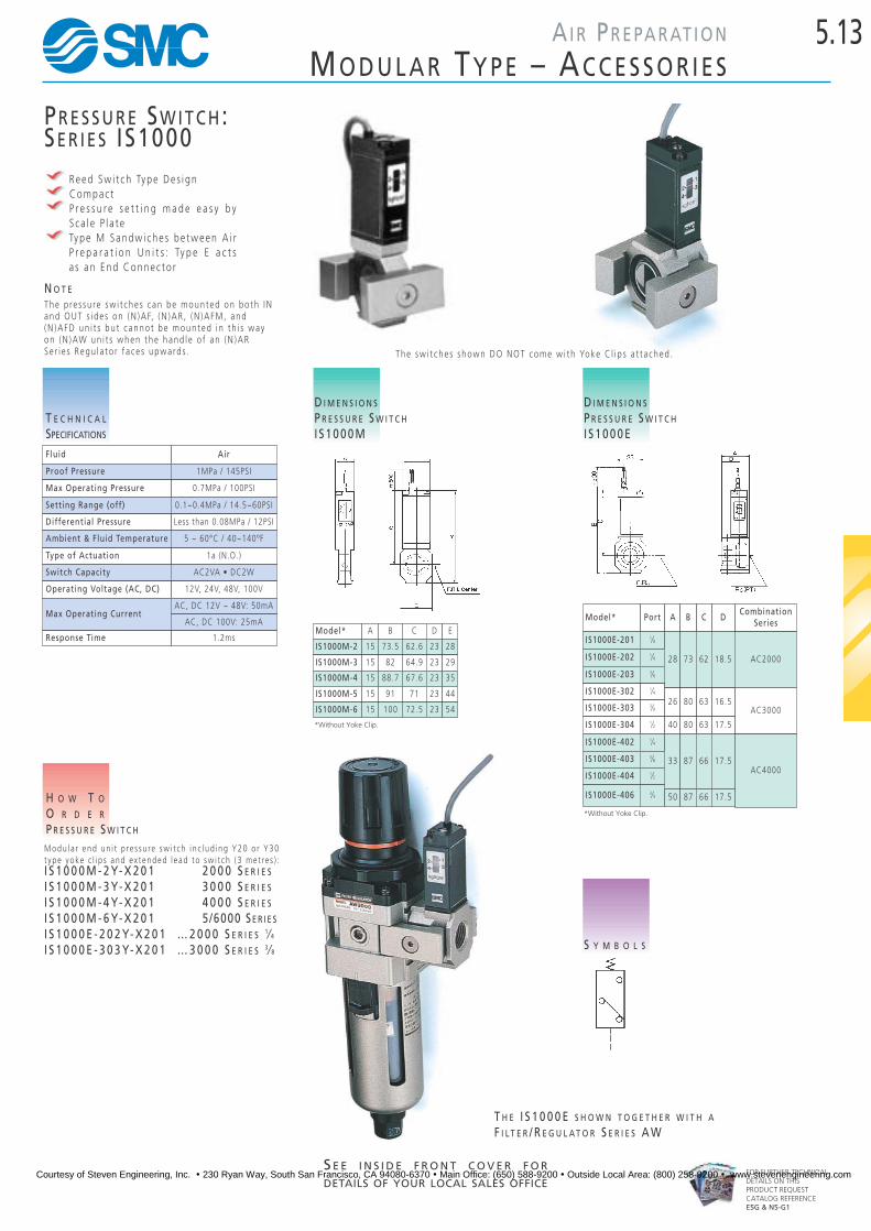
PR E S S U R E SW I T C H:SE R I E S IS1000
Reed Sw i t ch Type De s i gnCompac tP r e s s u r e s e t t i n g m a d e e a s y b yS ca l e P l a t eType M Sandw i che s be tween A i rP r e p a r a t i o n U n i t s : Ty p e E a c t sa s an End Connec to r
T E C H N I C A L
SPECIFICATIONS
S Y M B O L S
D I M E N S I O N S
P R E S S U R E S W I T C H
I S 1 0 0 0 M
D I M E N S I O N S
P R E S S U R E S W I T C H
I S 1 0 0 0 E
H O W T O
O R D E R
P R E S S U R E S W I T C H
Modu l a r end un i t p re s su re sw i t ch i n c l ud i ng Y20 o r Y30t ype yoke c l i p s and e x t ended l e ad t o sw i t ch ( 3 me t re s ) :I S 1 0 0 0 M - 2 Y- X 2 0 1 2 0 0 0 S E R I E S
I S 1 0 0 0 M - 3 Y- X 2 0 1 3 0 0 0 S E R I E S
I S 1 0 0 0 M - 4 Y- X 2 0 1 4 0 0 0 S E R I E S
I S 1 0 0 0 M - 6 Y- X 2 0 1 5/6000 SE R I E S
I S 1 0 0 0 E - 2 0 2 Y- X 2 0 1 … 2 0 0 0 S E R I E S 1⁄ 4
I S 1 0 0 0 E - 3 0 3 Y- X 2 0 1 … 3 0 0 0 S E R I E S 3 ⁄ 8
The p re s su re sw i t che s c an be moun ted on bo th INand OUT s i de s on (N )AF, (N )AR , (N )AFM, and(N )AFD un i t s bu t c anno t be moun ted i n t h i s wayon (N )AW un i t s when the hand l e o f an (N )ARSe r i e s Regu l a to r f a ce s upwa rd s .
N O T E
Model* Port A B C D
IS1000E-201 1⁄8
28 73 62 18.5IS1000E-202 1⁄4
AC4000
AC3000
IS1000E-203 3⁄8
AC2000
CombinationSeries
IS1000E-302 1⁄426 80 63 16.5
IS1000E-303 3⁄8
IS1000E-304 1⁄2 40 80 63 17.5
IS1000E-402 1⁄4
33 87 66 17.5IS1000E-403 3⁄8
IS1000E-404 1⁄2
IS1000E-406 3⁄4 50 87 66 17.5
T H E I S 1 0 0 0 E S H O W N T O G E T H E R W I T H A
F I L T E R / R E G U L A T O R S E R I E S A W
Fluid Air
Proof Pressure 1MPa / 145PSI
Max Operating Pressure 0.7MPa / 100PSI
Setting Range (off) 0.1~0.4MPa / 14.5~60PSI
Differential Pressure Less than 0.08MPa / 12PSI
Ambient & Fluid Temperature 5 ~ 60°C / 40~140ºF
Type of Actuation 1a (N.O.)
Switch Capacity AC2VA • DC2W
Operating Voltage (AC, DC) 12V, 24V, 48V, 100V
Max Operating CurrentAC, DC 12V ~ 48V: 50mA
AC, DC 100V: 25mA
Response Time 1.2msModel* A B C D E
IS1000M-2 15 73.5 62.6 23 28
IS1000M-3 15 82 64.9 23 29
IS1000M-4 15 88.7 67.6 23 35
IS1000M-5 15 91 71 23 44
IS1000M-6 15 100 72.5 23 54
The sw i t che s shown DO NOT come w i th Yoke C l i p s a t t a ched .
*Without Yoke Clip.
*Without Yoke Clip.
Courtesy of Steven Engineering, Inc. ! 230 Ryan Way, South San Francisco, CA 94080-6370 ! Main Office: (650) 588-9200 ! Outside Local Area: (800) 258-9200 ! www.stevenengineering.com

5.14
FOR FURTHER TECHNICALDETAILS ON THISPRODUCT REQUESTCATALOG REFERENCEE5G & N5-G1
A I R PR E PA R AT I O N
MO D U L A R TY P E – AC C E S S O R I E S
SH U T OF F VA LV ESE R I E S (N)VHS (3 PO RT RE L I E V I N G)
Re l i e v e s t he Downs t ream P re s su re f o r S y s t em Se r v i c i ngV i sua l Po s i t i on I i nd i c a t i on
SMC Pneuma t i c s ’ S e r i e s NVHS 3 Po r t Va l v e s p ro v i de a means t o p re ven ta c c i d e n t a l s t a r t - u p s w h i l e p e r s o n n e l a r e c l e a n i n g o r s e r v i c i n ge q u i p m e n t . W h e n i n t h e e x h a u s t p o s i t i o n , t h e v a l v e m a y b e p a d l o c k -s e cu red . To e l i m i n a t e a n y u n c e r t a i n t y o f v a l v e s t a t u s , a w i n d o w d i s p l a y s w h e nthe v a l v e i s i n s upp l y o r e xhau s t po s i t i on .
* Simple user modif icat ion al lows lock in pressure supply posit ion.
D I M E N S I O N S
S E R I E S ( N ) V H S S H U T- O F F VA LV E
D I M E N S I O N S
S E R I E S ( N ) V H S 3 P O R T VA LV E
W I T H L O C K I N G FA C I L I T Y
S Y M B O L S
H O W T O
O R D E R
S E R I E S ( N ) V H S S H U T- O F F V A L V E S
(N)VHS 00
2 …… 20003 ……2500 , 30004 …… 40005 ……5000 , 6000
B O D Y S I Z E A N D
A P P L I C A B L E F R L S E R I E S
0 ……Standa rd5 ……Lockab l e
L O C K I N G O P T I O N
01 …1/802 …1/403 …3/804 …1/206 …3/410 …1
I N P U T P O R T S I Z E
- …………Black Hand l e ; S i l v e r BodyX116 ……Red Hand l e ( Lo ckab l e ) ; S i l v e r Body - S t anda rdX1 …………Red Hand l e ; Red Body
H A N D L E C O L O R O P T I O N S
Model Port Size Exh Port A B C D E ØF G ØHNVHS2500 1/8, 1/4 1/8 60 20 12.8 40 44 33 28 7.5NVHS3500 1/4, 3/8 1/4 73 29 12.8 53 53 42 29 7.7NVHS4500 1/4, 3/8, 1/2 3/8 85 32 12.6 70 64 49 36 10NVHS5500 3/4, 1 1/2 136 56 32 90 80 65 54 10
Model Port Size Exh. Port A B C D E FNVHS2000 1/8, 1/4 1/8 40 56 36 28 22 25NVHS3000 1/4, 3/8 1/4 53 74 45 48 28 30NVHS4000 1/4, 3/8, 1/2 3/8 70 80 48 54 36 30
Lockable Unit. Color may not be available as shown.Please consult SMC Customer Service.
- ……Standa rdN ……Nor th Ame r i c an
Courtesy of Steven Engineering, Inc. ! 230 Ryan Way, South San Francisco, CA 94080-6370 ! Main Office: (650) 588-9200 ! Outside Local Area: (800) 258-9200 ! www.stevenengineering.com

5.15
FOR FURTHER TECHNICALDETAILS ON THISPRODUCT REQUESTCATALOG REFERENCEE5G & N5-G1
A I R PR E PA R AT I O N
MO D U L A R TY P E – AC C E S S O R I E S
S E E I N S I D E F R O N T C O V E R F O R
DETAILS OF YOUR LOCAL SALES OFFICE
L TY P E BR A C K E T
D I M E N S I O N S
L T Y P E B R A C K E T
H O W T O
O R D E R
L T Y P E B R A C K E TSpacer with Bracket B r a cke t On l y
1 0 0 0 S E R I E S … … Y 1 0 L . . . . B 1 1 0 L2 0 0 0 S E R I E S … … Y 2 0 L . . . . B 2 1 0 L3 0 0 0 S E R I E S … … Y 3 0 L . . . . B 3 1 0 L4 0 0 0 S E R I E S … … Y 4 0 L . . . . B 4 1 0 L4 0 0 0 - 0 6 S E R I E S … Y 5 0 L . . . . B 5 1 0 L5 / 6 0 0 0 S E R I E S … Y 5 0 L . . . . B 6 1 0 L
T TY P E BR A C K E T
D I M E N S I O N S
T T Y P E B R A C K E T
Spacer withT-type bracket
A B C D E F G R L
Y10T 20 12 4.5 3 25 5 8 2.25 27
Y20T 24 15 5.5 3 30 5 10 2.75 33
Y30T 35 16 7 4 41 7 11 3.5 45
Y40T 40 22 9 4 50 7 14 4.5 50
Y50T 40 22 9 4 50 7 14 4.5 50
Y60T 50 24 12 4 70 10 15 6 62.5
H
40
40
70
80
80
100
Spacer withL-type bracket
A B C D E F G R L
Y10L 20 12 4.5 3 25 5 8 2.25 27
Y20L 24 15 5.5 3 30 5 10 2.75 33
Y30L 35 16 7 4 41 7 11 3.5 45
Y40L 40 22 9 4 50 7 14 4.5 50
Y50L 40 22 9 4 50 7 14 4.5 50
Y60L 50 24 12 4 70 10 15 6 62.5
H O W T O
O R D E R
S P A C E R
Y 1 0 … ( 1 0 0 0 S E R I E S )Y 2 0 … ( 2 0 0 0 S E R I E S )Y 3 0 … ( 3 0 0 0 S E R I E S )Y 4 0 … ( 4 0 0 0 S E R I E S )Y 5 0 … ( 4 0 0 0 - 0 6 S E R I E S )Y 6 0 … ( 5 / 6 0 0 0 S E R I E S )
SPA C E R
D I M E N S I O N S
S P A C E R
Model A Applicable Model
Y10 8 NAC100~NAC1040
Y20 10 NAC2000~NAC2040
Y30 11NAC2500~NAC2540NAC3000~NAC3040
Y40 14 NAC4000~NAC4040
Y50 14 NAC4000-06~NAC4040-60
Y60 15NAC5000/5500/6000NAC5020/5520/6020
H O W T O
O R D E R
T T Y P E B R A C K E TSpacer with BracketB r a cke t On l y
1 0 0 0 S E R I E S … … Y 1 0 T . . . . B 1 1 0 T2 0 0 0 S E R I E S … … Y 2 0 T . . . . B 2 1 0 T3 0 0 0 S E R I E S … … Y 3 0 T . . . . B 3 1 0 T4 0 0 0 S E R I E S … … Y 4 0 T . . . . B 4 1 0 T4 0 0 0 - 0 6 S E R I E S … Y 5 0 T . . . . B 5 1 0 T5 / 6 0 0 0 S E R I E S … Y 6 0 T . . . . B 6 1 0 T
Courtesy of Steven Engineering, Inc. ! 230 Ryan Way, South San Francisco, CA 94080-6370 ! Main Office: (650) 588-9200 ! Outside Local Area: (800) 258-9200 ! www.stevenengineering.com

5.16
FOR FURTHER TECHNICALDETAILS ON THISPRODUCT REQUESTCATALOG REFERENCEE201, E5G & N5-G1
A I R PR E PA R AT I O N
MO D U L A R TY P E – AC C E S S O R I E S
EN D BL O C K AD A P T O R
Po r t S i z e s : M5 ~ 1”Rc A l l ows f o r e a s y i n s t a l l a t i on and ma in t enance
D I M E N S I O N S
P I P I N G A D A P T O R
H O W T O
O R D E R
P I P I N G A D A P T O R
E 1 0 - M 5 … … 1 0 0 0 S E R I E S
E 2 0 - N 0 1 … … 2 0 0 0 S E R I E S
E 2 0 - N 0 2 … … 2 0 0 0 S E R I E S
E 2 0 - N 0 3 … … 2 0 0 0 S E R I E S
E 3 0 - N 0 2 … … 3 0 0 0 S E R I E S
E 3 0 - N 0 3 … … 3 0 0 0 S E R I E S
E 3 0 - N 0 4 … … 3 0 0 0 S E R I E S
E 4 0 - N 0 3 … … 4 0 0 0 S E R I E S
E 4 0 - N 0 4 … … 4 0 0 0 S E R I E S
E 4 0 - N 0 6 … … 4 0 0 0 S E R I E S
E 6 0 - N 0 6 … … 5 / 6 0 0 0 S E R I E S
E 6 0 - N 1 0 … … 5 / 6 0 0 0 S E R I E S
CH E C K VA LV ESE R I E S (N)AKMT h e C h e c k Va l v e S p a c e r i s d e s i g n e d t o p r e v e n tback f l ow o f l ub r i c a t ed a i r f rom a l ub r i c a to r whenb o t h l u b r i c a t e d a n d n o n - l u b r i c a t e d s u p p l i e s a r erequ i red .
D I M E N S I O N S
C H E C K VA LV E S E R I E S N A K M
H O W T O
O R D E R
C H E C K VA LV E S E R I E S ( N ) A K M
(N)AKM
2 0 0 0 … … 2 0 0 0 S e r i e s3 0 0 0 … … 3 0 0 0 S e r i e s4 0 0 0 … … 4 0 0 0 S e r i e s
B O D Y S I Z E01 … 1⁄802 … 1⁄403 … 3⁄8
P O R T S I Z E
S Y M B O L S
Model Port Size A B C D
NAKM2000 1⁄8 1⁄4 40 40 28 11
NAKM3000 1⁄8 1⁄4 53 48 34 14
NAKM4000 1⁄4 3⁄8 70 54 42 18
E
11
13
15
Model Port size A B C
E10-M5 M5x0.8 16 17.5 14
E20-N01 1⁄8
E20-N02 1⁄4
E20-N03 3⁄8
23 22 22
E30-N02 1⁄4
E30-N03 3⁄826 34.2 29
E30-N04 1⁄2 40 34.2 29
E40-N03 3⁄8
E40-N04 1⁄233 42.2 35
E40-N06 3⁄4 50 42.2 35
E50-N06 3⁄4 36 44 46.2
E60-N06 3⁄4
E60-N10 140 54 55.2
- ……Rc ( PT )* Remove (N ) when o rde r i ngN ……NPT
P O R T T H R E A D
- …………Japane seN ………Nor th Ame r i c an
mm
mm
Courtesy of Steven Engineering, Inc. ! 230 Ryan Way, South San Francisco, CA 94080-6370 ! Main Office: (650) 588-9200 ! Outside Local Area: (800) 258-9200 ! www.stevenengineering.com

5.17
FOR FURTHER TECHNICALDETAILS ON THISPRODUCT REQUESTCATALOG REFERENCEE5G & N5-G1
A I R PR E PA R AT I O N
MO D U L A R TY P E – AC C E S S O R I E S
S E E I N S I D E F R O N T C O V E R F O R
DETAILS OF YOUR LOCAL SALES OFFICE
BR A N C H I N G UN I T S
D I M E N S I O N S
T TA K E O F F
D I M E N S I O N S
X TA K E O F F
Model Port Size A B CY11-M5 M5X0.8 8 12 8Y21-01 1/8 10 29 19Y21-02 1/4 10 29 19Y31-01 1/8 11 33 19Y31-02 1/4 11 33 19Y41-02 1/4 14 39 24Y41-03 3/8 14 39 24Y51-02 1/4 14 24 41Y52-03 3/8 14 24 41Y61-03 3/8 15 30 50.5Y61-04 1/2 15 30 50.5
Model Port Size A B C DY14-M5 M5 23 16 14 25Y24-01 1/8 40 40 22 40Y24-02 1/4 40 40 22 40Y34-02 1/8 49 43 28 48Y44-02 1/4 60 48 36 54Y44-03 3/8 60 48 36 54Y54-03 3/8 72 62 40 62Y54-04 1/2 72 62 40 62
H O W T O
O R D E R
" T " T A K E - O F F Y
1 … … 1 00 02 … … 2 00 03 … … 3 00 04 … … 4 00 05 ……4000 -066 ……5000 , 6000
A P P L I C A B L E F R L S E R I E S
1 ……"T" Type4 ……"X" Type
T A K E - O F F T Y P E
M5 …M5 x 0 .801 …1/802 …1/403 …3/804 …1/2
P O R T S I Z E
F i t s be tween modu l a r un i t su s i ng 'Y ' Type Connec to r s
Canno t be i n s t a l l ed ad j a cen t t ocomb ined f i l t e r / regu l a to r un i t
N i l …Rc ( PT )N ……NPT
T H R E A D T Y P E
mm mm
Courtesy of Steven Engineering, Inc. ! 230 Ryan Way, South San Francisco, CA 94080-6370 ! Main Office: (650) 588-9200 ! Outside Local Area: (800) 258-9200 ! www.stevenengineering.com

5.18
FOR FURTHER TECHNICALDETAILS ON THISPRODUCT CONSULTSMC CUSTOMER SERVICE
AI R PR E PA R AT I O N
F I LT E R S : H I G H EF F I C I E N C Y
HI G H FL O W AI R F I LT E R SE R I E S (N)AFPo r t S i z e s 1 1⁄2- 2”Rc , NPT, P F5µm F i l t e r E l emen tH igh E f f i c i en c y D r a i nageBow l Gua rd S t anda rd
S Y M B O L S
D I M E N S I O N S
A I R F I LT E R M O D E L S ( N ) A F 8 0 0 / 9 0 0D I M E N S I O N S
A I R F I LT E R M O D E L S ( N ) A F 8 1 1 / 9 1 1
ACCESSORIES
A I R F I LT E R
F i l t e r E l emen t s11345 -5B ………………………NAF80011352 -5B ………………………NAF900
T E C H N I C A L
SPECIFICATIONS
H O W T O
O R D E R
A I R F I LT E R
(N)AF800-12 (1 1⁄4)
(N)AF800-14 (1 1⁄2)
(N)AF900-20 (2 )
H O W T O
O R D E R
A I R F I LT E R W I T H A U T O D R A I N
(N)AF811-12 (1 1⁄4)
(N)AF811-14 (1 1⁄2)
(N)AF911-20 (2 )
Model A B C Pipe Size
(N)AF811 150 439 33 11⁄2, 11⁄4
(N)AF911 200 519 46 2
Model A B C Pipe Size
(N)AF800 150 410 33 11⁄2, 11⁄4
(N)AF900 200 488 46 2
Flows are for 0.7MPa Supply, 0.01MPa Pressure Drop
FOR FURTHER TECHNICAL DETAILS ON THIS
PRODUCT CONSULT SMC CUSTOMER SERVICE
FOR FURTHER TECHNICAL DETAILS ON THIS
PRODUCT CONSULT SMC CUSTOMER SERVICE
Pipe Size
(N)AF800 (N)AF900
Max Operating Pressure
11⁄2" 2"
Max Flow Rate ln/min 9000 15000
Drain Capacity (cm3) 180 180
1MPa / 145PSI
Ambient & Fluid Temp 5~60ºC / 40~140ºF
Bowl Polycarbonate
Note) (N)AFAF - JapaneseNAF - North American
Courtesy of Steven Engineering, Inc. ! 230 Ryan Way, South San Francisco, CA 94080-6370 ! Main Office: (650) 588-9200 ! Outside Local Area: (800) 258-9200 ! www.stevenengineering.com
5.19
FOR FURTHER TECHNICALDETAILS ON THISPRODUCT CONSULTSMC CUSTOMER SERVICE
AI R PR E PA R AT I O N
F I LT E R S : H I G H EF F I C I E N C Y
S E E I N S I D E F R O N T C O V E R F O R
DETAILS OF YOUR LOCAL SALES OFFICE
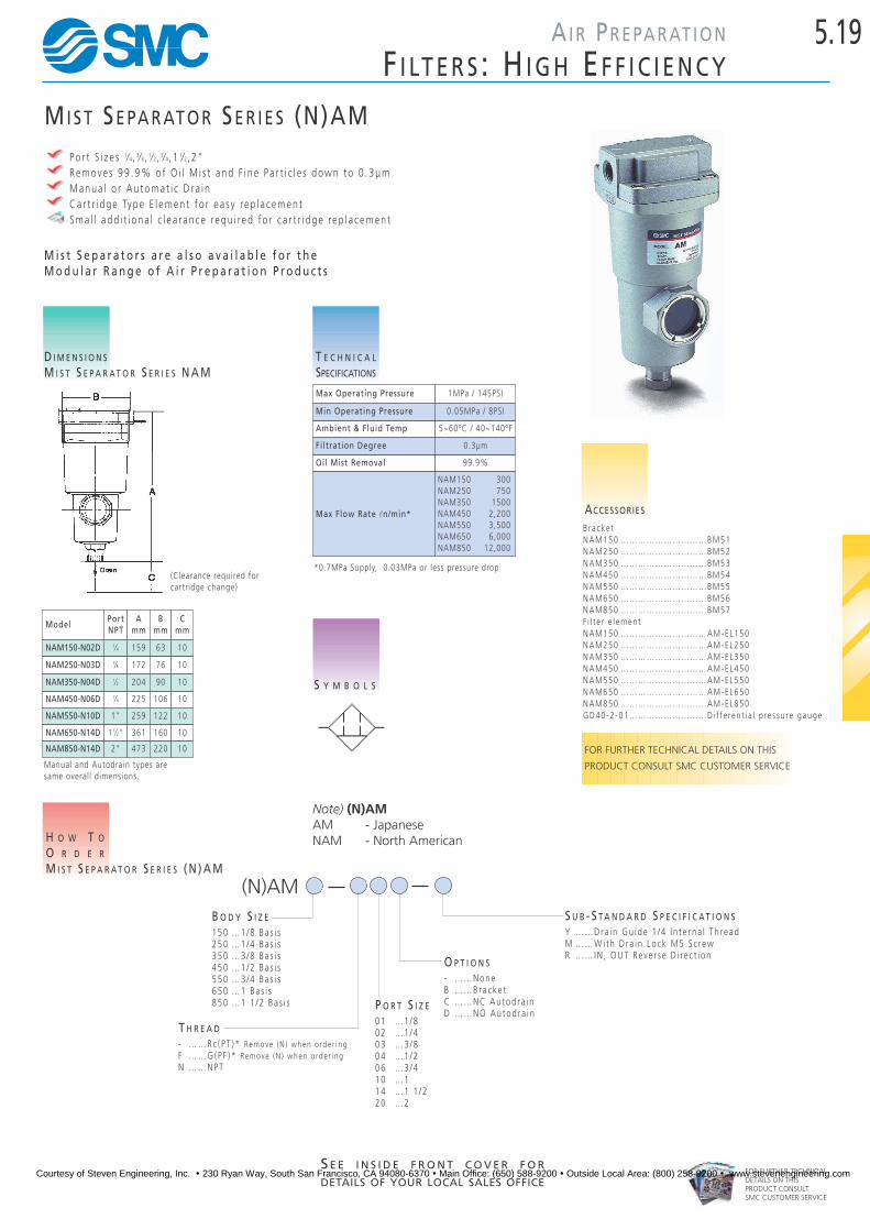
M i s t S e p a r a t o r s a r e a l s o a v a i l a b l e f o r t h eM o d u l a r R a n g e o f A i r P r e p a r a t i o n P r o d u c t s
MI S T SE PA R AT O R SE R I E S (N)AMPo r t S i z e s 1⁄4, 3⁄8, 1⁄2, 3⁄4, 1 1⁄2, 2"Remove s 99 .9% o f O i l M i s t and F i ne Pa r t i c l e s down to 0 .3µmManua l o r Au toma t i c D r a i nCa r t r i dge Type E l emen t f o r e a s y rep l a cemen tSma l l add i t i ona l c l e a r ance requ i red f o r c a r t r i dge rep l a cemen t
T E C H N I C A L
SPECIFICATIONS
H O W T O
O R D E R
M I S T S E P A R A T O R S E R I E S ( N ) A M
D I M E N S I O N S
M I S T S E P A R A T O R S E R I E S N A M
S Y M B O L S
(Clearance required forcartridge change)
Manual and Autodrain types aresame overall dimensions.
ACCESSORIES
B ra cke tNAM150 …………………………BM51NAM250 …………………………BM52NAM350 …………………………BM53NAM450 …………………………BM54NAM550 …………………………BM55NAM650 …………………………BM56NAM850 …………………………BM57F i l t e r e l emen tNAM150 …………………………AM-EL150NAM250 …………………………AM-EL250NAM350 …………………………AM-EL350NAM450 …………………………AM-EL450NAM550 …………………………AM-EL550 NAM650 …………………………AM-EL650NAM850 …………………………AM-EL850 GD40 -2 -01 ………………………Di f f e ren t i a l p re s su re gauge
*0.7MPa Supply, 0.03MPa or less pressure drop
ModelPortNPT
Amm
Bmm
Cmm
NAM450-N06D 3⁄4 225 106 10
NAM550-N10D 1" 259 122 10
NAM650-N14D 11⁄2" 361 160 10
NAM850-N14D 2" 473 220 10
NAM150-N02D 1⁄4 159 63 10
NAM250-N03D 3⁄8 172 76 10
NAM350-N04D 1⁄2 204 90 10
Max Operating Pressure 1MPa / 145PSI
Min Operating Pressure 0.05MPa / 8PSI
Ambient & Fluid Temp 5~60ºC / 40~140ºF
Filtration Degree 0.3µm
Oil Mist Removal 99.9%
Max Flow Rate ln/min*
NAM150 300NAM250 750NAM350 1500NAM450 2,200NAM550 3,500NAM650 6,000NAM850 12,000
FOR FURTHER TECHNICAL DETAILS ON THIS
PRODUCT CONSULT SMC CUSTOMER SERVICE
(N)AM
150 …1/8 Ba s i s250 …1/4 Ba s i s350 …3/8 Ba s i s450 …1/2 Ba s i s550 …3/4 Ba s i s650 …1 Ba s i s850 …1 1 /2 Ba s i s
B O D Y S I Z E
- ……Rc ( PT )* Remove (N ) when o rde r i ngF ……G(PF )* Remove (N ) when o rde r i ngN ……NPT
T H R E A D01 …1/802 …1/403 …3/804 …1/206 …3/410 …114 …1 1 /220 …2
P O R T S I Z E
- ……NoneB ……Bracke tC ……NC Au tod ra i nD ……NO Au tod ra i n
O P T I O N S
Y ……Dra in Gu ide 1 /4 I n t e r na l Th readM ……W i th D ra i n Lo ck M5 S c rewR ……IN , OUT Reve r s e D i re c t i on
S U B - S T A N D A R D S P E C I F I C A T I O N S
Note) (N)AMAM - JapaneseNAM - North American
Courtesy of Steven Engineering, Inc. ! 230 Ryan Way, South San Francisco, CA 94080-6370 ! Main Office: (650) 588-9200 ! Outside Local Area: (800) 258-9200 ! www.stevenengineering.com

5.20
FOR FURTHER TECHNICALDETAILS ON THISPRODUCT CONSULTSMC CUSTOMER SERVICE
AI R PR E PA R AT I O N
F I LT E R S : H I G H EF F I C I E N C Y
MI C R O MI S T SE PA R AT O R SE R I E S (N)AMDPo r t S i z e s 1⁄4, 3⁄8, 1⁄2, 3⁄4, 1" ,1 1⁄2, 2"Remove s O i l . Wa te r and D i r t f rom Compre s s ed A i r99 .9999% E f f i c i en tPa r t i c l e remova l down to 0 .01µmO i l Ca r r y -o ve r l e s s t han 0 .08 p .p .m .Ca r t r i dge Type E l emen t f o r e a s y rep l a cemen tSma l l add i t i ona l c l e a r ance requ i red f o r c a r t r i dge rep l a cemen t
H O W T O
O R D E R
M I S T S E P A R A T O R S E R I E S ( N ) A M D
D I M E N S I O N S
M I S T S E P A R A T O R S E R I E S N A M D
ACCESSORIES
M I S T S E P A R A T O R S E R I E S ( N ) A M DB ra cke t sNAMD150 ………………………BM51NAMD250 ………………………BM52NAMD350 ………………………BM53NAMD450 ………………………BM54NAMD550 ………………………BM55NAMD650 ………………………BM56NAMD850 ………………………BM57F i l t e r E l emen tNAMD150 ………………………AMD-EL150NAMD250 ………………………AMD-EL250NAMD350 ………………………AMD-EL350NAMD450 ………………………AMD-EL450NAMD550 ………………………AMD-EL550NAMD650 ………………………AMD-EL650NAMD850 ………………………AMD-EL850GD40 -2 -01 ………………………Di f f e ren t i a l p re s su re gauge
T E C H N I C A L
SPECIFICATIONS
ModelPortNPT
Amm
Bmm
Cmm
NAMD450-N06 3⁄4" 225 106 10
NAMD550-N10 1" 259 122 10
NAMD650-N14 11⁄2" 361 160 10
S Y M B O L S
(Clearance required forcartridge change)
Manual and Autodrain Types aresame overall dimensions.
*0.7MPa supply, 0.02MPa pressure drop
NAMD850-N20 2" 473 220 10
NAMD150-N02 1⁄4 159 63 10
NAMD250-N03 3⁄8 172 76 10
NAMD350-N04 1⁄2 204 90 10
Max Operating Pressure 1MPa / 145PSI
Minimum Operating Pressure 0.05MPa / 8 PSI
Ambient and Fluid Temperatures 5 - 60°C / 40~140ºF
Filtration Degree 0.01µm
Oil Mist Removal 99.9%
Max Flow Rate ln/min*
NAMD150 - 200NAMD250 - 250
NAMD350 - 1000NAMD450 - 2000NAMD550 - 3500NAMD650 - 6000
NAMD850 - 12000
(N)AMD
150 …1/8 Ba s i s250 …1/4 Ba s i s350 …3/8 Ba s i s450 …1/2 Ba s i s550 …3/4 Ba s i s650 …1 Ba s i s850 …1 1 /2 Ba s i s
B O D Y S I Z E
- ……Rc ( PT )* Remove (N ) when o rde r i ngF ……G(PF )* Remove (N ) when o rde r i ngN ……NPT
T H R E A D01 …1/802 …1/403 …3/804 …1/206 …3/410 …114 …1 1 /220 …2
P O R T S I Z E
- ……NoneB ……Bracke tC ……NC Au tod ra i nD ……NO Au tod ra i n
O P T I O N S
Y ……Dra in Gu ide 1 /4 I n t e r na lTh readM ……W i th D ra i n Lo ck M5 S c rewR ……IN , OUT Reve r s e D i re c t i on
S U B - S T A N D A R D S P E C I F I C A T I O N S
Note) (N)AMDAMD - JapaneseNAMD - North American
Courtesy of Steven Engineering, Inc. ! 230 Ryan Way, South San Francisco, CA 94080-6370 ! Main Office: (650) 588-9200 ! Outside Local Area: (800) 258-9200 ! www.stevenengineering.com
5.21
FOR FURTHER TECHNICALDETAILS ON THISPRODUCT CONSULTSMC CUSTOMER SERVICE
AI R PR E PA R AT I O N
F I LT E R S : H I G H EF F I C I E N C Y
S E E I N S I D E F R O N T C O V E R F O R
DETAILS OF YOUR LOCAL SALES OFFICE
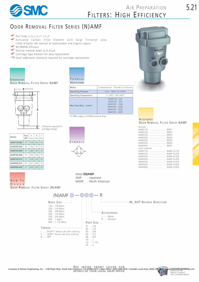
OD O R RE M O VA L F I LT E R SE R I E S (N)AMFPo r t S i z e s 1⁄4, 3⁄8, 1⁄2, 3⁄4, 1" ,1 1⁄2, 2"A c t i v a t e d C a r b o n F i l t e r E l e m e n t w i t h l a r g e f i l t r a t i o n a r e a ( 1420 m 2/ g ) f o r t he remova l o f h yd roca rbon and o rgan i c v apo r s99 .9999% E f f i c i en tPa r t i c l e remova l down to 0 .01µmCa r t r i dge Type E l emen t f o r e a s y rep l a cemen tSma l l add i t i ona l c l e a r ance requ i red f o r c a r t r i dge rep l a cemen t
T E C H N I C A L
SPECIFICATIONS
H O W T O
O R D E R
O D O R R E M O V A L F I L T E R S E R I E S ( N ) A M F
D I M E N S I O N S
O D O R R E M O V A L F I L T E R S E R I E S N A M F
ACCESSORIES
O D O R R E M O V A L F I L T E R S E R I E S N A M FB ra cke tNAMF150 ………………………BM51NAMF250 ………………………BM52NAMF350 ………………………BM53NAMF450 ………………………BM54NAMF550 ………………………BM55NAMF650 ………………………BM56NAMF850 ………………………BM57F i l t e r e l emen tNAMF150 ………………………NAMF-EL150NAMF250 ………………………NAMF-EL250NAMF350 ………………………NAMF-EL350NAMF450 ………………………NAMF-EL450NAMF550 ………………………NAMF-EL550NAMF650 ………………………NAMF-EL650NAMF850 ………………………NAMF-EL850
S Y M B O L S
(Clearance required forcartridge change)
ModelPortNPT
Amm
Bmm
Cmm
NAMF150-N02 1⁄4" 139 63 10
NAMF250-N03 3⁄8" 152 76 10
NAMF350-N04 1⁄2" 184 90 10
NAMF450-N06 3⁄4" 205 106 10
NAMF550-N10 1" 239 122 10
NAMF650-N14 11⁄2" 321 160 10
Media Compressed air - f i ltered to 10 micron
Operating Pressure 0.05 - 1MPa / 8~145PSI
Operating Temperature 5 - 60°C / 40~140ºF
Max Flow Rate ln/min*
NAMF150 - 200NAMF250 - 500
NAMF350 - 1000NAMF450 - 2000NAMF550 - 3500NAMF650 - 6000
*0.7MPa supply, 0.015MPa pressure drop
NAMF850-N20 2" 403 220 10
(N)AMF
150 …1/8 Ba s i s250 …1/4 Ba s i s350 …3/8 Ba s i s450 …1/2 Ba s i s550 …3/4 Ba s i s650 …1 Ba s i s850 …1 1 /2 Ba s i s
B O D Y S I Z E
- ……Rc ( PT )* Remove (N ) when o rde r i ngF ……G(PF )* Remove (N ) when o rde r i ngN ……NPT
T H R E A D01 …1/802 …1/403 …3/804 …1/206 …3/410 …114 …1 1 /220 …2
P O R T S I Z E
- ……NoneB ……Bracke t
A C C E S S O R I E S
I N , O U T R E V E R S E D I R E C T I O N
R
Note) (N)AMFAMF - JapaneseNAMF - North American
Courtesy of Steven Engineering, Inc. ! 230 Ryan Way, South San Francisco, CA 94080-6370 ! Main Office: (650) 588-9200 ! Outside Local Area: (800) 258-9200 ! www.stevenengineering.com

5.22
FOR FURTHER TECHNICALDETAILS ON THISPRODUCT CONSULTSMC CUSTOMER SERVICE
AI R PR E PA R AT I O N
F I LT E R S : WAT E R SE PA R AT O R
WAT E R SE PA R AT O R SE R I E S AMGPo r t S i z e s 1⁄4, 3⁄8, 1⁄2, 3⁄4, 1 , 1 1⁄2, 2"Remove s 99 .9% o f Wa te r D rop l e t sAu toma t i c D r a i n a s S t anda rdE l emen t i s re s i s t an t t o c l ogg ingSma l l add i t i ona l c l e a r ance requ i red f o r c a r t r i dge rep l a cemen t
T E C H N I C A L
SPECIFICATIONS
H O W T O
O R D E R
W A T E R S E P A R A T O R S E R I E S A M G
D I M E N S I O N S
W A T E R S E P A R A T O R S E R I E S A M G
S Y M B O L S
(Clearance required forcartridge change)
ACCESSORIES
B ra cke tAMG150 …………………………BM51AMG250 …………………………BM52AMG350 …………………………BM53AMG450 …………………………BM54AMG550 …………………………BM55AMG650 …………………………BM56AMG850 …………………………BM57
*0.7MPa Supply, 0.03MPa or less pressure drop
Max Operating Pressure 1MPa / 145PSI
Min Operating Pressure 0.15MPa / 22PSI
Ambient & Fluid Temp 5~60ºC / 40~140ºF
Max Flow Rate ln/min*
AMG150 300AMG250 750AMG350 1500AMG450 2200AMG550 3500AMG650 6000AMG850 12000
ModelPortNPT
Amm
Bmm
Cmm
AMG150 1⁄4 170 63 10
AMG250 3⁄8 191 76 10
AMG350 1⁄2 220 90 10
AMG450 3⁄4 241 106 10
AMG550 1 279 122 10
AMG650 1 1⁄2 388 160 10
AMG850 2 479 220 10
FOR FURTHER TECHNICAL INFORMATION
ON THIS SERIES, REFER TO CAT:E508
AMG
150 …1/8 Ba s i s250 …1/4 Ba s i s350 …3/8 Ba s i s450 …1/2 Ba s i s550 …3/4 Ba s i s650 …1 Ba s i s850 …1 1 /2 Ba s i s
B O D Y S I Z E
- ……Rc ( PT )* Remove (N ) when o rde r i ngF ……G(PF )* Remove (N ) when o rde r i ngN … …NPT
T H R E A D01 …1/802 …1/403 …3/804 …1/206 …3/410 …114 …1 1 /220 …2
P O R T S I Z E
N i l …NoneB ……Bracke tC ……NC Au tod ra i nD ……NO Au tod ra i n
O P T I O N S
S U B - S T A N D A R D S P E C I F I C A T I O N S
Courtesy of Steven Engineering, Inc. ! 230 Ryan Way, South San Francisco, CA 94080-6370 ! Main Office: (650) 588-9200 ! Outside Local Area: (800) 258-9200 ! www.stevenengineering.com

5.23AI R PR E PA R AT I O N
SE R I E S NAP100
FOR FURTHER TECHNICALDETAILS ON THISPRODUCT CONSULTSMC CUSTOMER SERVICE
S E E I N S I D E F R O N T C O V E R F O R
DETAILS OF YOUR LOCAL SALES OFFICE
PR E S S U R E CO N T R O L VA LV E
The (N )AP Se r i e s p re s su re re l i e f regu l a to r i s an ad j u s t ab l er e l i e f v a l v e w i t h a c o n t r o l r a n g e o f 1 8 ~ 1 0 0 P S I . I f ap r e s s u r e g r e a t e r t h a n t h e s e t p r e s s u r e i s r e a c h e d , t h eu n i t w i l l o p e n , c l o s i n g w h e n p r e s s u r e i s l e s s t h a n s e tp re s su re .
T E C H N I C A L
SPECIFICATIONSS Y M B O L S
ACCESSORIES
SERIES (N)AP100B ra cke t …………………………B21-1P
H O W T O
O R D E R
S E R I E S ( N ) A P 1 0 0
(N)AP100
01 … 1⁄8"02 … 1⁄4"
P O R T S I Z E
D I M E N S I O N S
( N ) A P S E R I E S
FOR FURTHER TECHNICAL DETAILS ON THIS
PRODUCT CONSULT SMC CUSTOMER SERVICE
Rc
Characteristics (N)AP100
Port Size 1⁄8" (01), 1⁄4" (02)
Max Operating Pressure 1MPa / 145PSI
Relieving Range 0.05 - 0.7MPa / 18~100PSI
Temperature Range 5 - 60ºC / 40~140ºF
Body Material Aluminum Die Cast - ……Rc ( PT )* Remove (N ) when o rde r i ngN ……NPT
T H R E A D
*BLACK HANDLE AVAILABLE IN NORTH AMERICA
- ……Japane seN ……Nor th Ame r i c an
Courtesy of Steven Engineering, Inc. ! 230 Ryan Way, South San Francisco, CA 94080-6370 ! Main Office: (650) 588-9200 ! Outside Local Area: (800) 258-9200 ! www.stevenengineering.com

5.24
FOR FURTHER TECHNICALDETAILS ON THISPRODUCT CONSULTSMC CUSTOMER SERVICE
AI R PR E PA R AT I O N
HI G H FL O W SE R I E S
PR E S S U R E RE G U L AT O RP I L O T AS S I S T E D
Compac t , L i gh twe igh t Cons t r u c t i onH igh F l ow Capac i t yS t ab l e Ac cu r a t e P re s su re Con t ro l
S Y M B O L S
ACCESSORIES
P I L O T O P E R AT E D P R E S S U R E R E G U L AT O R
Mount i ng B r a cke tB24 ………………………………NAR425B25 ………………………………NAR625
H O W T O
O R D E R
P I L O T O P E R AT E D P R E S S U R E R E G U L AT O R
D I M E N S I O N S
P I L O T O P E R AT E D P R E S S U R E R E G U L AT O R
T E C H N I C A L
SPECIFICATIONS
Bracket DimensionsModel A B C D E F
G H J
NAR425 80 141 37 67 71 (72) 3 50 48 80
NAR625 98 152 40 78 76.5 (77.5) 7 87 52 90
NAR825 126 217 75 110 92.5 (93.5) 5 - - -
NAR925 160 242 89 140 107.5 (108.5) 10 - - - -
-
B25
B24
BracketNo.
Pressure Regulating Range (Bar) 0.5 ~ 8.5 NAR425 NAR625 NAR825 NAR925
Pipe Size 1⁄4 3⁄8 1⁄2 3⁄4 1 11⁄2 2
Flow Rate ln/min 7bar suply, 1 bar pressure drop 8,000 14,000 18,000 22,000
1MPa = 145 PSI
(N)AR
4 ……1/26 …… 18 ……1 1 /29 …… 2
B O D Y S I Z E
25 …0.05~0 .83MPa
P R E S S U R E 01 …1/802 …1/403 …3/804 …1/206 …3/410 …114 …1 1 /220 …2
P O R T S I Z E
B ……Bracke tG ……Gauge
O P T I O N S
25
- ……Rc (PT )* Remove (N ) when o rde r i ngF ……F(PF )N ……NPT
T H R E A D
- ……Japane seN ……Nor th Ame r i c an
Courtesy of Steven Engineering, Inc. ! 230 Ryan Way, South San Francisco, CA 94080-6370 ! Main Office: (650) 588-9200 ! Outside Local Area: (800) 258-9200 ! www.stevenengineering.com

S E E I N S I D E F R O N T C O V E R F O R
DETAILS OF YOUR LOCAL SALES OFFICE
5.25AI R PR E PA R AT I O N
MI N I AT U R E RE G U L AT O R SE R I E S NARJ
FOR FURTHER TECHNICALDETAILS ON THISPRODUCT CONSULTSMC CUSTOMER SERVICE
MI N I AT U R E RE G U L AT O R (N)ARJ1020FCompac t De s i gnP i s t on Cons t r u c t i on o f f e r s H i gh F requency and Long L i f eOne -Touch Tube Connec t i onPane l Moun t
T E C H N I C A L
SPECIFICATIONS
S Y M B O L S
F L O W
SPECIFICATIONS
Flow ln/min
Primary Pressure – 7 Bar
Test condition–(init ialsettingPrimary pressure–7 BarSecondary pressure–2 BarFlow rate–10ln/min
Seco
ndar
y pr
essu
re B
ar
P R E S S U R E
SPECIFICATIONS
Primary pressure Bar
Seco
ndar
y pr
essu
re B
ar
H O W T O
O R D E R
M I N I A T U R E R E G U L A T O R ( N ) A R J 1 0 2 0 F
(N)ARJ1020F M504 …4mm06 …6mm
M5 …M5X0 .8
D I M E N S I O N S
S E R I E S N A R J
Panel Mount Dimension
Model A B C D E F G H J
NARJ1020F-M5-04 21 10.4 4M5X0.8 6 10.6 3.5 15.5 50
NARJ1020F-M5-06 22 12.8 6
Model
Media
Operating Pressure
Max Pressure
Temperature
PipingIN
OUT Ø4, Ø6
M5X0.8 male
5-60ºC / 40~140ºF
0.8MPa / 120PSI
0.1~0.7MPa / 14.5~100PSI
Air
NARJ1020F
- ……Japane seN ……Nor th Ame r i c an
Ø4, Ø6
Courtesy of Steven Engineering, Inc. ! 230 Ryan Way, South San Francisco, CA 94080-6370 ! Main Office: (650) 588-9200 ! Outside Local Area: (800) 258-9200 ! www.stevenengineering.com
5.26
FOR FURTHER TECHNICALDETAILS ON THISPRODUCT CONSULTSMC CUSTOMER SERVICE
AI R PR E PA R AT I O N
HI G H FL O W SE R I E S
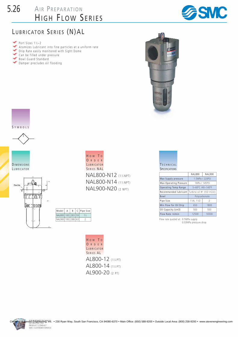
LU B R I C AT O R SE R I E S (N)ALPo r t S i z e s 1 1⁄2~2A tom i ze s Lub r i c an t i n to f i n e pa r t i c l e s a t a un i f o rm r a t eD r i p Ra t e ea s i l y mon i t o red w i t h S i gh t DomeCan be f i l l e d unde r p re s su reBow l Gua rd S t anda rdDampe r p re c l ude s o i l f l ood ing
S Y M B O L S
T E C H N I C A L
SPECIFICATIONS
D I M E N S I O N S
L U B R I C AT O R
H O W T O
O R D E R
L U B R I C AT O R
S E R I E S N A L
NAL800-N12 (1 1⁄4 NPT )
NAL800-N14 (1 1⁄2 NPT )
NAL900-N20 (2 NPT )
Model A B C Pipe Size
NAL800 100 283 59 11⁄2
NAL900 100 288 63 2
NAL800 NAL900
Max Supply pressure 1.5MPa / 220PSI
Max Operating Pressure 1MPa / 145PSI
Operating Temp Range 5~60ºC /40~140ºF
Recommended lubricant Turbine oil #1 ( ISO VG32)
Bowl Polycarbonate
Pipe Size 11⁄4, 11⁄2 2
Min Flow for Oil Drip 650 1800
Oil Capacity (cm3) 500 500
Flow Rate ln/min 12500 16500
Flow rate quoted at: 0.5MPa supply0.03MPa pressure drop
H O W T O
O R D E R
L U B R I C AT O R
S E R I E S A L
AL800-12 (1 1⁄4 P T )
AL800-14 (1 1⁄2 P T )
AL900-20 (2 PT )
Courtesy of Steven Engineering, Inc. ! 230 Ryan Way, South San Francisco, CA 94080-6370 ! Main Office: (650) 588-9200 ! Outside Local Area: (800) 258-9200 ! www.stevenengineering.com

5.27
FOR FURTHER TECHNICALDETAILS ON THISPRODUCT CONSULTSMC CUSTOMER SERVICE
AI R PR E PA R AT I O N
AU T O DR A I N S
S Y M B O L S
T E C H N I C A L
SPECIFICATIONS
H O W T O
O R D E R
A U T O D R A I N S E R I E S A D
AD402-02 (1/4) PTAD402-03 (3/8) PTAD402-04 (1/2) PTAD600-06 (3/4) PTAD600-10 (1) PT
D I M E N S I O N S
A D S E R I E S A U I T O D R A I N S
AU T O DR A I N SE R I E S (N)ADPo r t S i z e s 1⁄4~1F l oa t Type Au toma t i c D r a i n Va l v e
FOR FURTHER TECHNICAL DETAILS ON THIS
PRODUCT CONSULT SMC CUSTOMER SERVICE
Type
Operating Pressure
Max Supply Pressure
Max Operating Pressure
Ambient & Fluid Temperature
Port Size
Drain Port
(N)AD402 (N)AD600
1.5~9.9 Bar 3~9.9 Bar
22~145PSI 45~145PSI
15 Bar / 220PSI
9.9 Bar / 145PSI
5 ~ 60ºC / 40~140ºF
1/2 3/4, 1
3/4 3/4, 1
H O W T O
O R D E R
A U T O D R A I N S E R I E S N A D
NAD402-N02 (1/4) NPTNAD402-N03 (3/8) NPTNAD402-N04 (1/2) NPTNAD600-N06 (3/4) NPTNAD600-N10 (1) NPT
Courtesy of Steven Engineering, Inc. ! 230 Ryan Way, South San Francisco, CA 94080-6370 ! Main Office: (650) 588-9200 ! Outside Local Area: (800) 258-9200 ! www.stevenengineering.com

5.28
FOR FURTHER TECHNICALDETAILS ON THISPRODUCT CONSULTSMC CUSTOMER SERVICE
AI R PR E PA R AT I O N
AU T O DR A I N S
SE R I E S ADH 4000 HE AV Y AU T O DR A I N
Long L i f eRe l i ab l eLa rge Capac i t yNo R i s k o f Ba ck P re s su reEa s y Ope ra t i on and Ma in t enance
H O W T O
O R D E R
S E R I E S A D H 4 0 0 0 H E A V Y A U T O D R A I N
D I M E N S I O N S
S E E N E X T P A G E ☞
ADH4 00 04
M A X . O P E R A T I N G P R E S S U R E0 . . . . . . . . . . 1 . 0MPa1 . . . . . . . . . . 1 . 6MPa
Au to D ra i n Type F l oa t TypeAu to D ra i n Va l v e Type No rma l l y OpenMax Supp l y P re s su re 1 .5MPa / 220PS IMax Ope ra t i ng P re s su re 1 .0 MPa / 145PS IOpe ra t i ng P re s su re Range 0 .05 ~ 1 .0 MPa { 8~145PS I )Amb i en t and F l u i d Tempe ra tu re Compre s s ed A i r 5 ~ 60 ºC ( non - f ree z i ng ) Max E xhau s t D r a i n 400cc /m in ( a t p re s su re 0 . 7MPa , wa te r )We igh t 1 .2kg (w i t h b r a cke t : 1 . 3kg )Co lo r L i gh t G re y
T E C H N I C A L
SPECIFICATIONS
S Y M B O L S
FOR FURTHER TECHNICAL DETAILS ON THIS
PRODUCT CONSULT SMC CUSTOMER SERVICE
Bracket BM58Ball Valve Piping Kit ADH-C400(See note below)Silencer for Drain 2506-004-X228
ACCESSORIES
Note : The Ba l l Va l v e P i p i ng K i t i n c l ude s a ba l l v a l v e , two ba r re ln i pp l e s and an e l bow. I t c an be f i t t ed t o t he i n l e t o f t he un i tand a l l ows i t t o be i s o l a t ed f o r e xam ina t i on and ma in t enance .
FOR FURTHER TECHNICAL INFORMATION ON
THIS SERIES, PLEASE REFER TO CAT:E408
T H R E A D- . . . . . . . . . . R c ( PT )N . . . . . . . . . .NPT
Courtesy of Steven Engineering, Inc. ! 230 Ryan Way, South San Francisco, CA 94080-6370 ! Main Office: (650) 588-9200 ! Outside Local Area: (800) 258-9200 ! www.stevenengineering.com

5.29
FOR FURTHER TECHNICALDETAILS ON THISPRODUCT CONSULTSMC CUSTOMER SERVICE
AI R PR E PA R AT I O N
AU T O DR A I N S
M6 Hex Cap Bolt(applicable hex. wrench normal size 5)
M6 Hex Cap Bolt(applicable hex. wrench normal size 5)
D I M E N S I O N S
Pilot Exhaust Port (both sides)
Bleed Valve
Label
Flushing Button
Bracket Mounting Hole (both sides)
Drain Inlet 1⁄2 Female ThreadSee “How To Order” for type of thread.
Drain Inlet 1⁄2 Female ThreadSee “How To Order” for type of thread.
Bracket (Option)
(Space for maintenance)
Sight Glass (both sides)
Width across flat part
Optional SpecificationReference Figure of Assembly
Piping example of ball valve piping set
Courtesy of Steven Engineering, Inc. ! 230 Ryan Way, South San Francisco, CA 94080-6370 ! Main Office: (650) 588-9200 ! Outside Local Area: (800) 258-9200 ! www.stevenengineering.com

5.30 AI R OP E R AT E D PR O D U C T S
BO O S T E R RE G U L AT O R
FOR FURTHER TECHNICALDETAILS ON THISPRODUCT REQUESTCATALOG REFERENCEN1-02
BO O S T E R RE G U L AT O R SE R I E S (N)VBAI n c rea se s Ma in L i ne P re s su reCompac t De s i gnP ro t e c t s Downs t ream Equ ipmen t f rom P re s su re F l u c tua t i on sI n c rea se s t he powe r o f a c tua to r w i t hou t chang ing t o a l a r ge r c y l i nde rNo need f o r e l e c t r i c a l i npu tOp t i ona l A i r Tank s f o r h i gh demandP re s su re Gauge s and S i l en ce r s i n c l udedRemote Ad ju s tmen t po s s i b l e
H O W T O
O R D E R
( N ) V B A B O O S T E R R E G U L A T O R
(N)VBA 0
1 … … 1⁄4”2 … … 3⁄8”4 … … 1⁄2”
B O D Y S I Z E
1 ……Hand l e2 ……Ai r P i l o t ( VBA 2000 , 4000 on l y )
P R E S S U R E A D J U S T M E N T
02 …1/4” ( 1110 )03 …3/8” ( 2100 , 2200 )04 …1/2” ( 4100 , 4200 )
P O R T I N G
0 ……1MPa Max ( 2000 , 4000 Se r i e s )1 ……2MPa Max ( 1000 Se r i e s )
P R E S S U R E R A N G E
ACCESSORIES
(N)VBA BOOSTER REGULATOR
S P A R E S K I T SKT-VBA2100 -P …………………(N)VBA2000 Se r i e sKT-VBA4100 -P …………………(N)VBA4000 Se r i e s
T E C H N I C A L
SPECIFICATIONS
The Boo s t e r Regu l a to r s hou ld be i n s t a l l ed w i t hi t s p i s t on i n a ho r i zon t a l po s i t i on .
INSTALLATION
D I M E N S I O N S
S E E N E X T P A G E ☞
S Y M B O L
*Pressure IN=OUT=10 Bar**Pressure IN=OUT=5 Bar
Specification (N)VBA1
Media Air
Proof Pressure 3MPa
Max Working Pressure 2MPa
Set Pressure Range 0.2 ~ 2MPa
Ambient and Media Temp Range 0 ~ 50°C / 32~125ºF
Lubrication Not Required
Installation Horizontal
Pressure Adjustable Mechanism Relieving Type
(N)VBA2, (N)VBA4
Air
1.5MPa
1MPa
0.2 ~ 1MPa
0 ~ 50°C / 32~125ºF
Not Required
Horizontal
Relieving Type
Pressure Increase Ratio Max. 2:1 Max. 2:1
3⁄8
Handle Type
3⁄8
Air Pilot Operated Type
Weight
Type(N)VBA2100-03 (N)VBA4100-04 (N)VBA2200-03 (N)VBA4200-04
Max Flow* 1000 ln/min** 1900 ln/min** 1000 ln/min** 1900 ln/min*
Port Size (IN, OUT) 3⁄8 1⁄2 3⁄8 1⁄2
EXH Port Size 1⁄2
7.5 kg
1⁄2
7.5 kg
Pilot EXH Port Size –
3.8 kg
1⁄8
3.8 kg
Pilot Pressure –
0.85 kg
1 ~ 5 Bar
(N)VBA1110-02
400 ln/min*
1⁄4
1⁄4
FOR FURTHER TECHNICAL DETAILS ON THIS
PRODUCT CONSULT SMC CUSTOMER SERVICE
T ……NPTF* Remove (N ) when o rde r i ngF ……G(PF )* Remove (N ) when o rde r i ngN ……NPT
P O R T T H R E A D
G ……Pre s su re GaugeN ……S i l ence r
O P T I O N
1MPa = 145PSI
- ……Japane seN ……Nor th Ame r i c an
Courtesy of Steven Engineering, Inc. ! 230 Ryan Way, South San Francisco, CA 94080-6370 ! Main Office: (650) 588-9200 ! Outside Local Area: (800) 258-9200 ! www.stevenengineering.com

5.31AI R OP E R AT E D PR O D U C T S
BO O S T E R RE G U L AT O R
FOR FURTHER TECHNICALDETAILS ON THISPRODUCT REQUESTCATALOG REFERENCEN1-02
( N ) V B A 2 , ( N ) V B A 4F L O W C H A R A C T E R I S T I C S
( N ) V B A 1F L O W C H A R A C T E R I S T I C S
D I M E N S I O N S
H A N D L E T Y P E
( N ) V B A 1 1 1 0 - 0 2
Secondary air flow ln/min
Pre
ssur
e P
2B
ar
Secondary air flow ln/min
Pre
ssur
e P
2B
ar
N V B A 1C H A R G E C H A R A C T E R I S T I C S
Pressure increase ratio (P2/P1)
Cha
rgin
g tim
e fo
r 10
lt(
s)
( N ) V B A 2 , ( N ) V B A 4C H A R G E C H A R A C T E R I S T I C S
Pressure increase ratio (P2/P1)
Cha
rgin
g tim
e fo
r 10
lt(
s)
Mounting Hole
Examp l e :(N )VBA 4P1 = 5 ba rP2 = 8 ba rThen max imum f l ow demand = 1000 � n /m in
These graphs illustrate the time required to inrease pressure in a closed tank e.g. (V)BA 1If we wish to increase tank pressure to 8 bar, where P1� 4 bar and tank pressure� 6.4 bar:
initial � � 1.6 (charging line from graph � 15 seconds)
final � � 2 (charging line from graph � 65 seconds)
Time taken to increase pressure � 65 � 15 seconds� 50 seconds per 10 litre volume of tank
8�4
p2�p1
6.4�4
p2�p1
PressureGauge
Port
Port SilencerIN/Port
OUT/Port
Courtesy of Steven Engineering, Inc. ! 230 Ryan Way, South San Francisco, CA 94080-6370 ! Main Office: (650) 588-9200 ! Outside Local Area: (800) 258-9200 ! www.stevenengineering.com

5.32 AI R OP E R AT E D PR O D U C T S
BO O S T E R RE G U L AT O R
FOR FURTHER TECHNICALDETAILS ON THISPRODUCT REQUESTCATALOG REFERENCEN1-02
D I M E N S I O N S
H A N D L E T Y P E
( N ) V B A 2 1 0 0 - 0 3 , ( N ) V B A 4 1 0 0 - 0 4
Model Port Size A B C D E F G H J K L ØM
(N)VBA2100-(N)03 3⁄8 300 170 53 118 98 44 45 60.5 18 15 – 31
(N)VBA4100-(N)04 1⁄2 404 207.5 96 150 130 62.8 62 90 17 15 40 40
Model Port Size A B C D E F G H J K L
(N)VBA2200-(N)03 3⁄8 300 126.5 53 118 98 44 45 60.5 18 15 –
(N)VBA4200-(N)04 1⁄2 404 167 96 150 130 62.8 62 90 17 15 40
D I M E N S I O N S
A I R P I L O T O P E R AT E D T Y P E
( N ) V B A 2 2 0 0 - 0 3 , ( N ) V B A 4 2 0 0 - 0 4
mm
mm
Courtesy of Steven Engineering, Inc. ! 230 Ryan Way, South San Francisco, CA 94080-6370 ! Main Office: (650) 588-9200 ! Outside Local Area: (800) 258-9200 ! www.stevenengineering.com

5.33AI R PR E PA R AT I O N: AC C E S S O R I E S
PR E S S U R E GA U G E S
FOR FURTHER TECHNICALDETAILS ON THISPRODUCT CONSULT SMC CUSTOMER SERVICE
PR E S S U R E GA U G E S
3 P re s su re Range sCen te r Ba ck o r P ane l Moun t1⁄8 o r 1⁄4 Connec t i on40 o r 50mm D i ame te r F a ce
H O W T O
O R D E R
P R E S S U R E G A U G E S
Fo r A i r P repa r a t i on s e r i e s (N )AR / (N )AW1000 , u s e SMC Gauge Pa r t Numbe r :
G27-10-R1 1⁄16 Connec t i on
N O T E
D I M E N S I O N S
G 2 7 - 1 0 - R 1D I M E N S I O N S
5 K 8 - 1 0 P / 4 P / 2 . 5 PD I M E N S I O N S
4 K 8 - 1 0 P / 4 P / 2 . 5 P
VA C U U M GA U G E S
Sca l e i n mmHgCen te r Ba ck Moun t1⁄8 o r 1⁄4 Connec t i on42mm D i ame te r F a ce
H O W T O
O R D E R
V A C U U M G A U G E S
GZ46 A
01 …1/802 …1/4
C O N N E C T I O N T H R E A D
- ……Rc ( PT )N ……NPT
T H R E A D T Y P E
M ……M5 (10 -32Nom) F ema l e
I N T E R N A L T H R E A D
- ……Standa rdC ……Pane l
Moun t i ng
M O U N T I N G
MODEL PORT SIZE PRESSURE RANGE APPLICABLE MODEL
G27-P10-R1 Rc(PT)1/16 0 ~ 150PSI NAR1000 • NAW1000
K10 1/8NPT 0 ~ 160PSI NAR2000 • 2500 • NAW2000 • 3000
K12 1/4NPT 0 ~ 160PSI NAR4000 • NAW4000
K13 1/4NPT 0 ~ 30PSI NAR4000 • NAW4000
K20 1/8NPT 0 ~ 30PSI NAR2000 • 2500 • NAW2000 • 3000
Courtesy of Steven Engineering, Inc. ! 230 Ryan Way, South San Francisco, CA 94080-6370 ! Main Office: (650) 588-9200 ! Outside Local Area: (800) 258-9200 ! www.stevenengineering.com

5.34 AI R PR E PA R AT I O N: AC C E S S O R I E S
S I L E N C E R S SE R I E S (N)AN
FOR FURTHER TECHNICALDETAILS ON THISPRODUCT, REQUESTCATALOG REFERENCEN510
Model NAN101-01 NAN110-01 NAN120-M3 NAN120-M5
Port Size 1⁄8”* 1⁄8”* M3 M5
Noise Reduction (dB) 16 21 13 18
Max Operating Pressure 1MPa / 145PSI
Ambient & Fluid Temperature 5~150°C / 40~300ºF
Effective Orifice mm2 (Cv) 20 (1.1) 35 (1.9) 1 (0.05) 5 (0.27)
Weight (gf) 9.5 20 1 3.3
ModelPort Size*
NPTEffective Orif ice
mm2 (Cv)
NAN200-N02 1⁄4” 35 (1.9)
NAN300-N03 3⁄8” 60 (3.3)
NAN400-N04 1⁄2” 90 (5.0)
NAN500-N06 3⁄4” 160 (8.8
NAN600-N10 1 270 (15)
NAN700-N12 11⁄4 440 (24)
NAN800-N14 11⁄2 590 (33)
NAN900-N20 2 960 (53)
Model A ØB
NAN101-N01 22.5 11
NAN110-N01 38 13
NAN120-M3 9 6
NAN120-M5 17 8
ModelDimensions (mm)
A B D
NAN200-N02 63 22 19
NAN300-N03 84 25 22
NAN400-N04 92 30 27
NAN500-N06 107 46 36
NAN600-N10 132 50 41
NAN700-N12 200 74 55
NAN800-N14 233 74 60
NAN900-N20 263 86 70
SE R I E S (N)AN S I L E N C E RM3, M5, 1⁄ 8 S I N T E R E D BR O N Z E
Su i t ab l e f o r m in i a tu re v a l v e s and p i l o t a i r e xhau s t po r t s13 - 21 dB no i s e reduc t i on
T E C H N I C A L
SPECIFICATIONS
S Y M B O L S
D I M E N S I O N S
SERIES NAN SILENCER
NAN120-M3 (M3)NAN120-M5 (M5)NAN110-N01 (1⁄8 NPT)NAN101-N01 (1⁄8 NPT)
SE R I E S (N)AN S I L E N C E R1⁄ 4~2
Ove r 30 dB no i s e reduc t i onLow back p re s su reCompac t and ea s y moun t i ng
S Y M B O L S
D I M E N S I O N S
SERIES NAN SILENCER
T E C H N I C A L
SPECIFICATIONS
H O W T O
O R D E R
SERIES NAN SILENCER
H O W T O
O R D E R
SERIES NAN SILENCER
*Tapered thread ISO7/1
Max Operating Pressure 1MPa / 145PSI
Noise Reduction 30dB or more
Ambient & Fluid Temperature 5~60°C / 40~140ºF
AN120-M3 (M3)AN120-M5 (M5)AN110-01 (1⁄8 PT)AN101-01 (1⁄8 PT)
H O W T O
O R D E R
SERIES AN SILENCER
Note: When ordering PT Ports, remove (N) from Model NumberEg: AN200-02
Courtesy of Steven Engineering, Inc. ! 230 Ryan Way, South San Francisco, CA 94080-6370 ! Main Office: (650) 588-9200 ! Outside Local Area: (800) 258-9200 ! www.stevenengineering.com
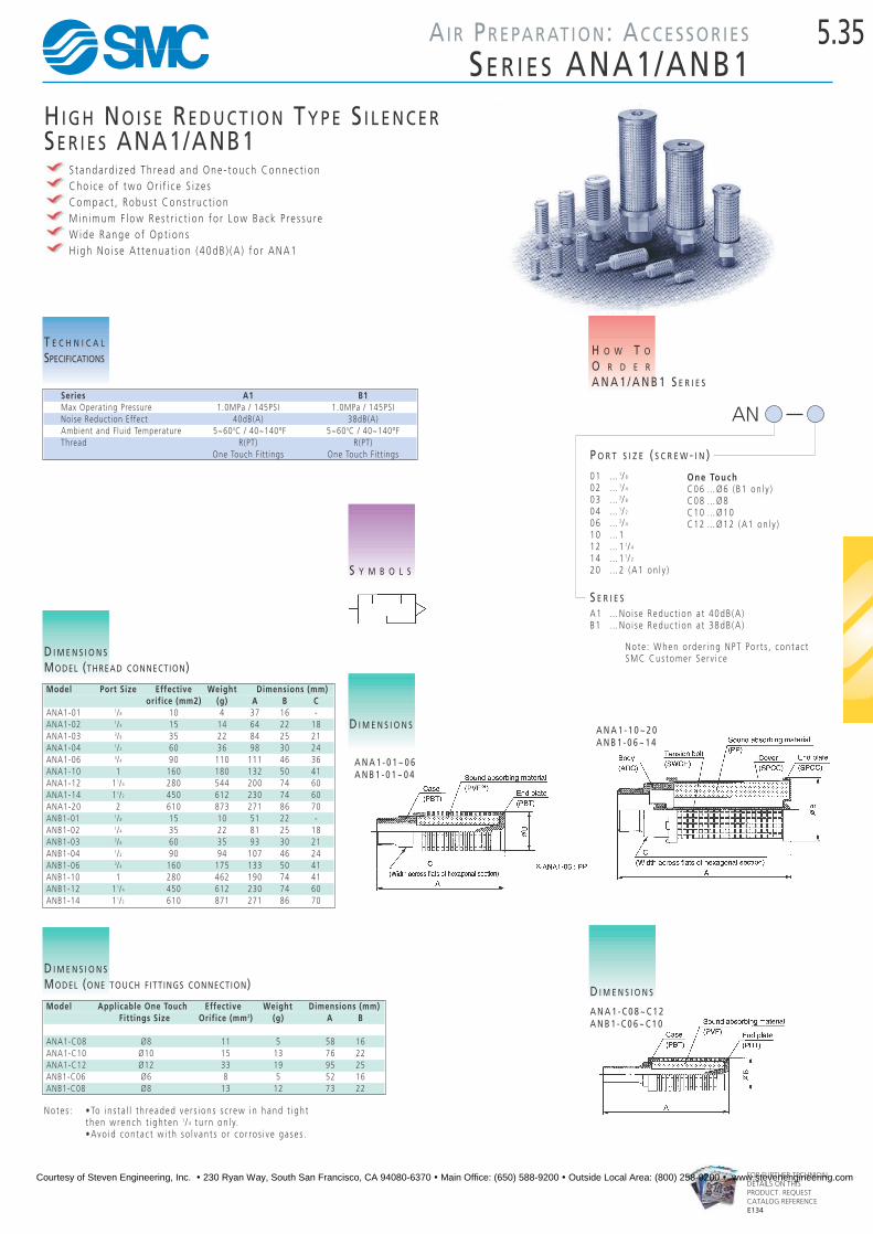
5.35AI R PR E PA R AT I O N: AC C E S S O R I E S
SE R I E S ANA1/ANB1
FOR FURTHER TECHNICALDETAILS ON THISPRODUCT. REQUESTCATALOG REFERENCEE134
H I G H NO I S E RE D U C T I O N TY P E S I L E N C E RSE R I E S ANA1/ANB1
S t anda rd i z ed Th read and One - touch Connec t i onCho i c e o f two O r i f i c e S i z e sCompac t , Robus t Cons t r u c t i onM in imum F l ow Re s t r i c t i on f o r Low Back P re s su reW ide Range o f Op t i on sH igh No i s e A t t enua t i on ( 40dB ) (A ) f o r ANA1
Series A1 B1Max Operating Pressure 1.0MPa / 145PSI 1.0MPa / 145PSINoise Reduction Effect 40dB(A) 38dB(A)Ambient and Fluid Temperature 5~600C / 40~140ºF 5~600C / 40~140ºFThread R(PT) R(PT)
One Touch Fitt ings One Touch Fitt ings
T E C H N I C A L
SPECIFICATIONS
AN
H O W T O
O R D E R
A N A 1 / A N B 1 S E R I E S
A1 …No i s e Reduc t i on a t 40dB (A )B1 …No i s e Reduc t i on a t 38dB (A )
S E R I E S
01 … 1/ 8
02 … 1/ 4
03 … 3/ 8
04 … 1/ 2
06 … 3/ 4
10 …112 …1 1/ 4
14 …1 1/ 2
20 …2 (A1 on l y )
P O R T S I Z E ( S C R E W - I N )
S Y M B O L S
Model Port Size Effective Weight Dimensions (mm)orifice (mm2) (g) A B C
ANA1-01 1/8 10 4 37 16 -ANA1-02 1/4 15 14 64 22 18ANA1-03 3/8 35 22 84 25 21ANA1-04 1/2 60 36 98 30 24ANA1-06 3/4 90 110 111 46 36ANA1-10 1 160 180 132 50 41ANA1-12 11/4 280 544 200 74 60ANA1-14 11/2 450 612 230 74 60ANA1-20 2 610 873 271 86 70ANB1-01 1/8 15 10 51 22 -ANB1-02 1/4 35 22 81 25 18ANB1-03 3/8 60 35 93 30 21ANB1-04 1/2 90 94 107 46 24ANB1-06 3/4 160 175 133 50 41ANB1-10 1 280 462 190 74 41ANB1-12 11/4 450 612 230 74 60ANB1-14 11/2 610 871 271 86 70
D I M E N S I O N S
MODEL (THREAD CONNECTION)
Model Applicable One Touch Effective Weight Dimensions (mm)Fittings Size Orifice (mm2) (g) A B
ANA1-C08 Ø8 11 5 58 16ANA1-C10 Ø10 15 13 76 22ANA1-C12 Ø12 33 19 95 25ANB1-C06 Ø6 8 5 52 16ANB1-C08 Ø8 13 12 73 22
D I M E N S I O N S
MODEL (ONE TOUCH FITTINGS CONNECTION)
Note s : •To i n s t a l l t h readed v e r s i on s s c rew i n hand t i gh tthen w rench t i gh t en 1/ 4 t u r n on l y.•Avo id con t a c t w i t h so l v an t s o r co r ro s i v e ga se s .
D I M E N S I O N S
A N A 1 - 1 0 ~ 2 0A N B 1 - 0 6 ~ 1 4
A N A 1 - C 0 8 ~ C 1 2A N B 1 - C 0 6 ~ C 1 0
One TouchC06 …Ø6 (B1 on l y )C08 …Ø8C10 …Ø10C12 …Ø12 (A1 on l y )
D I M E N S I O N S
A N A 1 - 0 1 ~ 0 6A N B 1 - 0 1 ~ 0 4
Note : When o rde r i ng NPT Po r t s , con t a c tSMC Cus tome r Se r v i c e
Courtesy of Steven Engineering, Inc. ! 230 Ryan Way, South San Francisco, CA 94080-6370 ! Main Office: (650) 588-9200 ! Outside Local Area: (800) 258-9200 ! www.stevenengineering.com

5.36 AI R PR E PA R AT I O N: AC C E S S O R I E S
EX H A U S T CL E A N E R SE R I E S NAMC
FOR FURTHER TECHNICALDETAILS ON THISPRODUCT, REQUESTCATALOG REFERENCEE5G
ModelMale Female
NAMC310 NAMC510 NAMC610 NAMC810 NAMC910 NAMC220 NAMC320 NAMC520
Port Size NPT 3⁄8” 3⁄4” 1 11⁄2 2 1⁄4” 1⁄4•3⁄8” 1⁄2•3⁄4”
Max Air Flow (Nl/min) 300 1,000 3,000 6,000 10,000 200 300 1,000
Effective Orifice mm2 (Cv) 16 (0.88) 55 (3.1) 165 (9.2) 330 (18.3) 550 (31) 12 (0.66) 16 (0.88) 55 (3.1)
Element Model No 635321 635521 635619 635812P 635917P 63522 635321 635521
Bracket Model No BE30 BE50 BE60 – – BE20 BE30 BE50
Max Operating Temperature 60°C / 140ºF
Noise Reduction 35dB or more
Oil Mist Removal 99.9% or more
Exhaust of Oil Mist Drain cock
Option Bracket*
*Bracket not available on NAMC810 and 910
SE R I E S (N)AMCEX H A U S T CL E A N E R
E n s u re s C l e a n P l a n t A i r a n d N o i s e R e d u c t i o no f d i s t r i bu t i ng no i s e con t am ina t i onOve r 35 dB No i s e Reduc t i onOve r 99 .9% O i l M i s t Remova lT E C H N I C A L
SPECIFICATIONS
ACCESSORIES
SERIES (N)AMC EXHAUST CLEANER
E l emen t …………………………See ”How To O rde r“B ra cke t …………………………See ”How To O rde r“
S Y M B O L S
H O W T O
O R D E R
N A M C S E R I E S
FOR MORE TECHNICAL INFORMATION ON THIS
SERIES, PLEASE CONSULT SMC CUSTOMER SERVICE
(N)AMC
2 ……1/43 ……3/85 ……3/46 …… 18 ……1 1 /29 …… 2
B O D Y S I Z E
- ……R(PT )* Remove (N ) when o rde r i ngN ……NPT
T H R E A D1 ……Ma le2 ……Fema l e(On l y NAMC220 , 320 , 520Spec i a l O rde r On l y )
T H R E A D
02 …1/403 …3/804 …1/206 …3/410 …114 …1 1 /220 …2
P O R T S I Z E
H O W T O
O R D E R
E X H A U S T C L E A N E R S E R I E S ( N ) A M C
0
B ……Bracke tD ……Threaded D ra i n Po r t ( F ema l e )
O P T I O N
- ……Japane seN ……Nor th Ame r i c an
Courtesy of Steven Engineering, Inc. ! 230 Ryan Way, South San Francisco, CA 94080-6370 ! Main Office: (650) 588-9200 ! Outside Local Area: (800) 258-9200 ! www.stevenengineering.com