Embed Size (px)
Citation preview
Air Motors
aerospaceclimate control electromechanicalfiltrationfluid & gas handlinghydraulicspneumaticsprocess controlsealing & shielding
P1V-S, stainless steel type - 0.02 to 1.2 kWP1V-S, high torque type - 0.28, 0.57 & 0.86 kWP1V-S, drilling, milling & grinding types - 0.08 to 1 kWCatalogue PDE2554TCUK October 2015
2
Parker Hannifin CorporationPneumatic Division - Europe
PDE2554TCUK
P1V-S - Air Motors
SALE CONDITIONSThe items described in this document are available for sale by Parker Hannifin Corporation, its subsidiaries or its authorized distributors. Any sale contract entered into by Parker will be governed by the provisions stated in Parker’s standard terms and conditions of sale (copy available upon request).
WARNING
FAILURE OR IMPROPER SELECTION OR IMPROPER USE OF THE PRODUCTS AND/OR SYSTEMS DESCRIBED HEREIN OR RELATED ITEMS CAN CAUSE DEATH, PERSONAL INJURY ANDPROPERTY DAMAGE.This document and other information from Parker Hannifin Corporation, its subsidiaries and authorized distributors provide product and/or system options for further investigation by users having technical expertise. It is important that you analyze all aspects of your application and review the information concerning the product or system in the current product catalog. Due to the variety of operating conditions and applications for these products or systems, the user, through its own analysis and testing, is solely responsible for making the final selection of the products and systems and assuring that all performance, safety and warning requirements of the application are met. The products described herein, including without limitation, product features, specifications, designs, availability and pricing, are subject to change by Parker Hannifin Corporation and its subsidiaries at any time without notice.
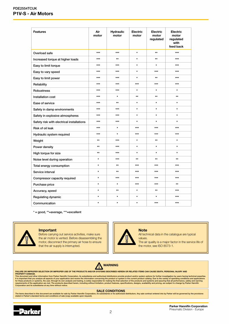
NoteAll technical data in the catalogue are typical values. The air quality is a major factor in the service life of the motor, see ISO 8573-1.
ImportantBefore carrying out service activities, make sure the air motor is vented. Before disassembling the motor, disconnect the primary air hose to ensure that the air supply is interrupted.
Features Air Hydraulic Electric Electric Electric motor motor motor motor motor regulated regulated with feed back
Overload safe *** *** * ** ***
Increased torque at higher loads *** ** * ** ***
Easy to limit torque *** *** * * ***
Easy to vary speed *** *** * *** ***
Easy to limit power *** *** * ** ***
Reliability *** *** *** *** ***
Robustness *** *** * * *
Installation cost *** * ** ** **
Ease of service *** ** * * *
Safety in damp environments *** *** * * *
Safety in explosive atmospheres *** *** * * *
Safety risk with electrical installations *** *** * * *
Risk of oil leak *** * *** *** ***
Hydraulic system required *** * *** *** ***
Weight ** *** * ** *
Power density ** *** * * *
High torque for size ** *** * * *
Noise level during operation * *** ** ** **
Total energy consumption * ** *** *** ***
Service interval * ** *** *** ***
Compressor capacity required * *** *** *** ***
Purchase price * * *** *** **
Accuracy, speed * ** * ** ***
Regulating dynamic * * * * ***
Communication * * * *** ***
* = good, **=average, ***=excellent
3
Parker Hannifin CorporationPneumatic Division - Europe
PDE2554TCUK
P1V-S - Air Motors
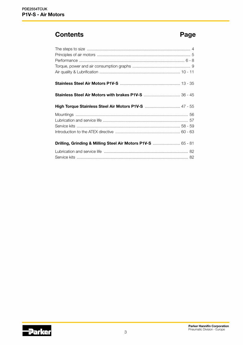
Contents Page
The steps to size ........................................................................................... 4Principles of air motors .................................................................................. 5Performance ............................................................................................. 6 - 8Torque, power and air consumption graphs ................................................... 9Air quality & Lubrification ....................................................................... 10 - 11
Stainless Steel Air Motors P1V-S ..................................................... 13 - 35
Stainless Steel Air Motors with brakes P1V-S ................................ 36 - 45
High Torque Stainless Steel Air Motors P1V-S ............................... 47 - 55
Mountings ................................................................................................... 56Lubrication and service life ........................................................................... 57Service kits ........................................................................................... 58 - 59Introduction to the ATEX directive ......................................................... 60 - 63
Drilling, Grinding & Milling Steel Air Motors P1V-S ........................ 65 - 81
Lubrication and service life .......................................................................... 82Service kits .................................................................................................. 82
4
Parker Hannifin CorporationPneumatic Division - Europe
PDE2554TCUK
P1V-S - Air Motors
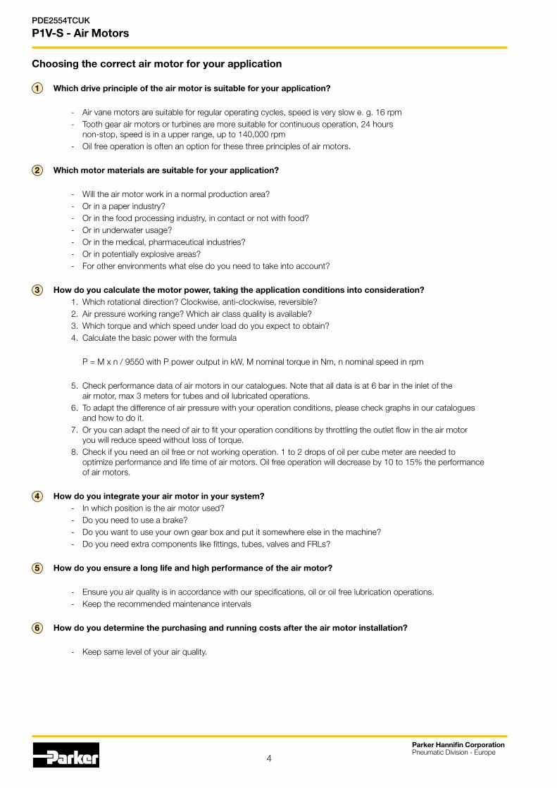
Choosing the correct air motor for your application
1 Which drive principle of the air motor is suitable for your application?
- Air vane motors are suitable for regular operating cycles, speed is very slow e. g. 16 rpm - Tooth gear air motors or turbines are more suitable for continuous operation, 24 hours non-stop, speed is in a upper range, up to 140,000 rpm - Oil free operation is often an option for these three principles of air motors.
2 Which motor materials are suitable for your application?
- Will the air motor work in a normal production area? - Or in a paper industry? - Or in the food processing industry, in contact or not with food? - Or in underwater usage? - Or in the medical, pharmaceutical industries? - Or in potentially explosive areas? - For other environments what else do you need to take into account?
3 How do you calculate the motor power, taking the application conditions into consideration? 1. Which rotational direction? Clockwise, anti-clockwise, reversible? 2. Air pressure working range? Which air class quality is available? 3. Which torque and which speed under load do you expect to obtain? 4. Calculate the basic power with the formula
P = M x n / 9550 with P power output in kW, M nominal torque in Nm, n nominal speed in rpm
5. Check performance data of air motors in our catalogues. Note that all data is at 6 bar in the inlet of the air motor, max 3 meters for tubes and oil lubricated operations. 6. To adapt the difference of air pressure with your operation conditions, please check graphs in our catalogues and how to do it. 7. Or you can adapt the need of air to fit your operation conditions by throttling the outlet flow in the air motor you will reduce speed without loss of torque. 8. Check if you need an oil free or not working operation. 1 to 2 drops of oil per cube meter are needed to optimize performance and life time of air motors. Oil free operation will decrease by 10 to 15% the performance of air motors.
4 How do you integrate your air motor in your system? - In which position is the air motor used? - Do you need to use a brake? - Do you want to use your own gear box and put it somewhere else in the machine? - Do you need extra components like fittings, tubes, valves and FRLs?
5 How do you ensure a long life and high performance of the air motor?
- Ensure you air quality is in accordance with our specifications, oil or oil free lubrication operations. - Keep the recommended maintenance intervals
6 How do you determine the purchasing and running costs after the air motor installation?
- Keep same level of your air quality.
5
Parker Hannifin CorporationPneumatic Division - Europe
PDE2554TCUK
P1V-S - Air Motors
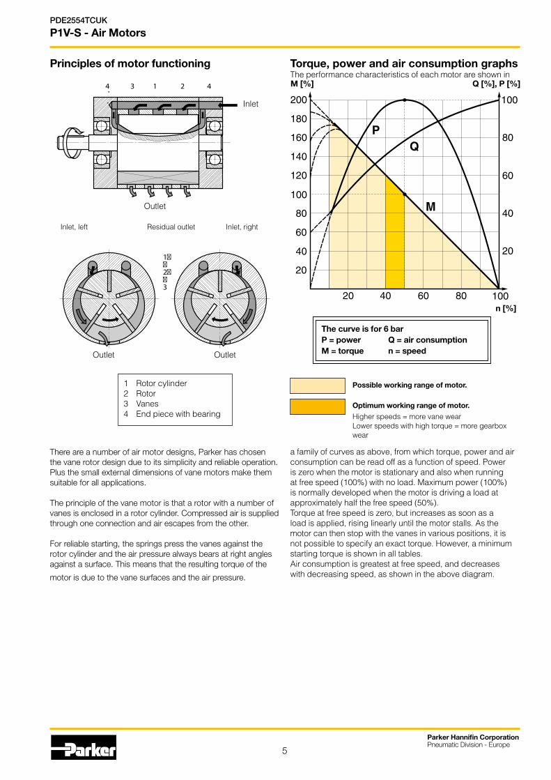
Principles of motor functioning
There are a number of air motor designs, Parker has chosen the vane rotor design due to its simplicity and reliable operation. Plus the small external dimensions of vane motors make them suitable for all applications.
The principle of the vane motor is that a rotor with a number of vanes is enclosed in a rotor cylinder. Compressed air is supplied through one connection and air escapes from the other.
For reliable starting, the springs press the vanes against the rotor cylinder and the air pressure always bears at right angles against a surface. This means that the resulting torque of the
motor is due to the vane surfaces and the air pressure.
Inlet
Inlet, left Residual outlet Inlet, right
1 Rotor cylinder2 Rotor3 Vanes4 End piece with bearing
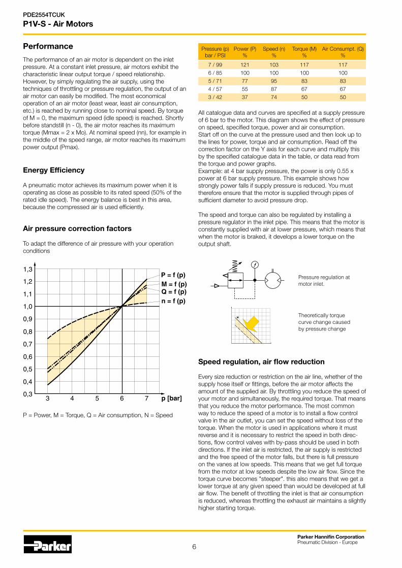
a family of curves as above, from which torque, power and airconsumption can be read off as a function of speed. Poweris zero when the motor is stationary and also when runningat free speed (100%) with no load. Maximum power (100%)is normally developed when the motor is driving a load atapproximately half the free speed (50%).Torque at free speed is zero, but increases as soon as aload is applied, rising linearly until the motor stalls. As themotor can then stop with the vanes in various positions, it isnot possible to specify an exact torque. However, a minimumstarting torque is shown in all tables.Air consumption is greatest at free speed, and decreaseswith decreasing speed, as shown in the above diagram.
Torque, power and air consumption graphsThe performance characteristics of each motor are shown in
1��2��3
Outlet Outlet
4 3 1 2 4
Outlet
4020 60 80 100
160
120
140
200
180
100
100
20
40
60
80
20
40
60
80M
QP
Q [%], P [%]M [%]
n [%]
Possible working range of motor.
Optimum working range of motor.
Higher speeds = more vane wearLower speeds with high torque = more gearbox wear
The curve is for 6 barP = power Q = air consumption M = torque n = speed
6
Parker Hannifin CorporationPneumatic Division - Europe
PDE2554TCUK
P1V-S - Air Motors
Performance
The performance of an air motor is dependent on the inlet pressure. At a constant inlet pressure, air motors exhibit the characteristic linear output torque / speed relationship. However, by simply regulating the air supply, using the techniques of throttling or pressure regulation, the output of an air motor can easily be modified. The most economical operation of an air motor (least wear, least air consumption, etc.) is reached by running close to nominal speed. By torque of M = 0, the maximum speed (idle speed) is reached. Shortly before standstill (n - 0), the air motor reaches its maximum torque (Mmax = 2 x Mo). At nominal speed (nn), for example in the middle of the speed range, air motor reaches its maximum power output (Pmax).
Energy Efficiency
A pneumatic motor achieves its maximum power when it is operating as close as possible to its rated speed (50% of the rated idle speed). The energy balance is best in this area, because the compressed air is used efficiently.
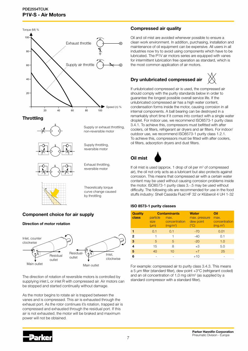
Air pressure correction factors
To adapt the difference of air pressure with your operation conditions
n = f (p)
p [bar]
Q = f (p)M = f (p)P = f (p)
0,4
0,3
0,5
0,6
0,7
0,8
0,9
1,0
1,1
1,2
1,3
3 4 5 6 7
P = Power, M = Torque, Q = Air consumption, N = Speed
All catalogue data and curves are specified at a supply pressure of 6 bar to the motor. This diagram shows the effect of pressure on speed, specified torque, power and air consumption. Start off on the curve at the pressure used and then look up to the lines for power, torque and air consumption. Read off the correction factor on the Y axis for each curve and multiply this by the specified catalogue data in the table, or data read from the torque and power graphs.Example: at 4 bar supply pressure, the power is only 0.55 x power at 6 bar supply pressure. This example shows how strongly power falls if supply pressure is reduced. You must therefore ensure that the motor is supplied through pipes of sufficient diameter to avoid pressure drop.
The speed and torque can also be regulated by installing a pressure regulator in the inlet pipe. This means that the motor is constantly supplied with air at lower pressure, which means that when the motor is braked, it develops a lower torque on the output shaft.
Speed regulation, air flow reduction
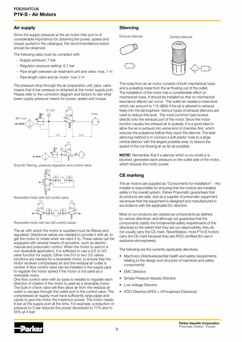
Every size reduction or restriction on the air line, whether of the supply hose itself or fittings, before the air motor affects the amount of the supplied air. By throttling you reduce the speed of your motor and simultaneously, the required torque. That means that you reduce the motor performance. The most common way to reduce the speed of a motor is to install a flow control valve in the air outlet, you can set the speed without loss of the torque. When the motor is used in applications where it must reverse and it is necessary to restrict the speed in both direc-tions, flow control valves with by-pass should be used in both directions. If the inlet air is restricted, the air supply is restricted and the free speed of the motor falls, but there is full pressure on the vanes at low speeds. This means that we get full torque from the motor at low speeds despite the low air flow. Since the torque curve becomes "steeper". this also means that we get a lower torque at any given speed than would be developed at full air flow. The benefit of throttling the inlet is that air consumption is reduced, whereas throttling the exhaust air maintains a slightly higher starting torque.
Pressure regulation at motor inlet.
M Theoretically torque curve change caused by pressure change
Pressure (p) Power (P) Speed (n) Torque (M) Air Consumpt. (Q) bar / PSI % % % %
7 / 99 121 103 117 117
6 / 85 100 100 100 100
5 / 71 77 95 83 83
4 / 57 55 87 67 67
3 / 42 37 74 50 50
7
Parker Hannifin CorporationPneumatic Division - Europe
PDE2554TCUK
P1V-S - Air Motors
Supply or exhaust throttling, non-reversible motor
M
Throttling
Theoretically torque curve change causedby throttling
Exhaust throttling, reversible motor
Supply throttling, reversible motor
Component choice for air supply
Direction of motor rotation
Exhaust throttle
Supply air throttle
Speed (n) %
Torque (M) % Compressed air quality
Oil and oil mist are avoided whenever possible to ensure a clean work environment. In addition, purchasing, installation and maintenance of oil equipment can be expensive. All users in all industries now try to avoid using components which have to be lubricated. The P1V air motors series are equipped with vanes for intermittent lubrication free operation as standard, which is the most common application of air motors.
Dry unlubricated compressed air
If unlubricated compressed air is used, the compressed air should comply with the purity standards below in order to guarantee the longest possible overall service life. If the unlubricated compressed air has a high water content, condensation forms inside the motor, causing corrosion in all internal components. A ball bearing can be destroyed in a remarkably short time if it comes into contact with a single water droplet. For indoor use, we recommend ISO8573-1 purity class 3.4.1. To achieve this, compressors must befitted with after coolers, oil filters, refrigerant air dryers and air filters. For indoor/outdoor use, we recommend ISO8573-1 purity class 1.2.1. To achieve this, compressors must be fitted with after coolers, oil filters, adsorption dryers and dust filters.
Oil mist
If oil mist is used (approx. 1 drop of oil per m3 of compressed air), the oil not only acts as a lubricant but also protects against corrosion. This means that compressed air with a certain water content may be used without causing corrosion problems inside the motor. ISO8573-1 purity class 3.-.5 may be used without difficulty. The following oils are recommended for use in the food stuffs industry: Shell Cassida Fluid HF 32 or Klüberoil 4 UH 1-32
ISO 8573-1 purity classes
Quality Contaminants Water Oil class particle max. max. pressure max. size concentration dew point concentration (µm) (mg/m3) (°C) (mg.m3)
1 0.1 0.1 -70 0.01
2 1 1 -40 0.1
3 5 5 -20 1.0
4 15 8 +3 5.0
5 40 10 +7 25
6 - - +10 -
For example: compressed air to purity class 3.4.3. This means a 5 µm filter (standard filter), dew point +3°C (refrigerant cooled) and an oil concentration of 1,0 mg oil/m3 (as supplied by a standard compressor with a standard filter).
Main outlet Main outlet
Residual outlet
Residual-outlet
Inlet, counter clock wise
Inlet, clockwise
The direction of rotation of reversible motors is controlled by supplying inlet L or inlet R with compressed air. Air motors can be stopped and started continually without damage. As the motor begins to rotate air is trapped between the vanes and is compressed. This air is exhausted through the exhaust port. As the rotor continues it’s rotation, trapped air is compressed and exhausted through the residual port. If this air is not exhausted, the motor will be braked and maximum power will not be obtained.
8
Parker Hannifin CorporationPneumatic Division - Europe
PDE2554TCUK
P1V-S - Air Motors
Air supply
Since the supply pressure at the air motor inlet port is of considerable importance for obtaining the power, speed and torque quoted in the catalogue, the recommendations below should be observed.
The following data must be complied with:
- Supply pressure: 7 bar
- Regulator pressure setting: 6.7 bar
- Pipe length between air treatment unit and valve: max. 1 m
- Pipe length valve and air motor: max 2 m
Shut-off, filtering, pressure regulation and control valve
Reversible motor with 5/3 control valve
Reversible motor with two 3/2 control valves
13
2
15
3 24
13
2 13
2
The pressure drop through the air preparation unit, pipe, valve means that 6 bar pressure is obtained at the motor supply port. Please refer to the correction diagram and factors to see what lower supply pressure means for power, speed and torque.
The air with which the motor is supplied must be filtered and regulated. Directional valves are needed to provide it with air, to get the motor to rotate when we want it to. These valves can be equipped with several means of actuation, such as electric, manual and pneumatic control. When the motor is used in a non-reversible application, it is sufficient to use a 2/2 or 3/2 valve function for supply. Either one 5/3 or two 3/2 valves functions are needed for a reversible motor, to ensure that the motor receives compressed air and the residual air outlet is vented. A flow control valve can be installed in the supply pipe to regulate the motor speed if the motor is not used as a reversible motor.One flow control valve with by-pass is needed to regulate each direction of rotation if the motor is used as a reversible motor. The built-in check valve will then allow air from the residual air outlet to escape through the outlet port in the control valve. The compressed air supply must have sufficiently large pipes and valves to give the motor the maximum power. The motor needs 6 bar at the supply port all the time. For example, a reduction of pressure to 5 bar reduces the power developed to 77% and to 55% at 4 bar!
Exhaust silencer Central silencer
Silencing
CE marking
The air motors are supplied as “Components for installation” – the installer is responsible for ensuring that the motors are installed safely in the overall system. Parker Pneumatic guarantees that its products are safe, and as a supplier of pneumatic equipment we ensure that the equipment is designed and manufactured in accordance with the applicable EU directive. Most of our products are classed as components as defined by various directives, and although we guarantee that the components satisfy the fundamental safety requirements of the directives to the extent that they are our responsibility, they do not usually carry the CE mark. Nevertheless, most P1V-S motors carry the CE mark because they are ATEX certified (for use in explosive atmospheres).
The following are the currently applicable directives:
• Machinery Directive(essential health and safety requirements relating to the design and structure of machines and safety components)
• EMC Directive
• Simple Pressure Vessels Directive
• Low Voltage Directive
• ATEX Directive (ATEX = ATmosphere EXplosive)
The noise from an air motor consists of both mechanical noise and a pulsating noise from the air flowing out of the outlet. The installation of the motor has a considerable effect on mechanical noise. It should be installed so that no mechanical resonance effects can occur. The outlet air creates a noise level which can amount to 115 dB(A) if the air is allowed to exhaust freely into the atmosphere. Various types of exhaust silencers are used to reduce this level. The most common type screwsdirectly onto the exhaust port of the motor. Since the motor function causes the exhaust air to pulsate, it is a good idea to allow the air to exhaust into some kind of chamber first, which reduces the pulsations before they reach the silencer. The best silencing method is to connect a soft plastic hose to a large central silencer with the largest possible area, to reduce the speed of the out-flowing air as far as possible.
NOTE! Remember that if a silencer which is too small or is blocked, generates back pressure on the outlet side of the motor, which reduces the motor power.
9
Parker Hannifin CorporationPneumatic Division - Europe
PDE2554TCUK
P1V-S - Air Motors
4020
7 bar6 bar5 bar4 bar3 bar
60 80 100
160
120
140
200
220
240
180
100
100
120
20
40
60
80
20
40
60
80
M
M [%]
n [%]
Q
P
Q [%], P [%]
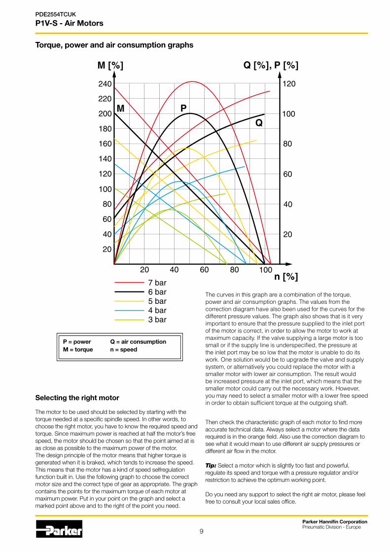
Torque, power and air consumption graphs
P = power Q = air consumption M = torque n = speed
The curves in this graph are a combination of the torque, power and air consumption graphs. The values from the correction diagram have also been used for the curves for the different pressure values. The graph also shows that is it very important to ensure that the pressure supplied to the inlet port of the motor is correct, in order to allow the motor to work at maximum capacity. If the valve supplying a large motor is too small or if the supply line is underspecified, the pressure at the inlet port may be so low that the motor is unable to do its work. One solution would be to upgrade the valve and supply system, or alternatively you could replace the motor with a smaller motor with lower air consumption. The result would be increased pressure at the inlet port, which means that the smaller motor could carry out the necessary work. However, you may need to select a smaller motor with a lower free speed in order to obtain sufficient torque at the outgoing shaft.
Selecting the right motor
The motor to be used should be selected by starting with the torque needed at a specific spindle speed. In other words, to choose the right motor, you have to know the required speed and torque. Since maximum power is reached at half the motor’s free speed, the motor should be chosen so that the point aimed at is as close as possible to the maximum power of the motor.The design principle of the motor means that higher torque is generated when it is braked, which tends to increase the speed. This means that the motor has a kind of speed selfregulation function built in. Use the following graph to choose the correct motor size and the correct type of gear as appropriate. The graph contains the points for the maximum torque of each motor at maximum power. Put in your point on the graph and select a marked point above and to the right of the point you need.
Then check the characteristic graph of each motor to find more accurate technical data. Always select a motor where the data required is in the orange field. Also use the correction diagram to see what it would mean to use different air supply pressures or different air flow in the motor.
Tip: Select a motor which is slightly too fast and powerful, regulate its speed and torque with a pressure regulator and/or restriction to achieve the optimum working point.
Do you need any support to select the right air motor, please feel free to consult your local sales office.
10
Parker Hannifin CorporationPneumatic Division - Europe
PDE2554TCUK
P1V-S - Air Motors
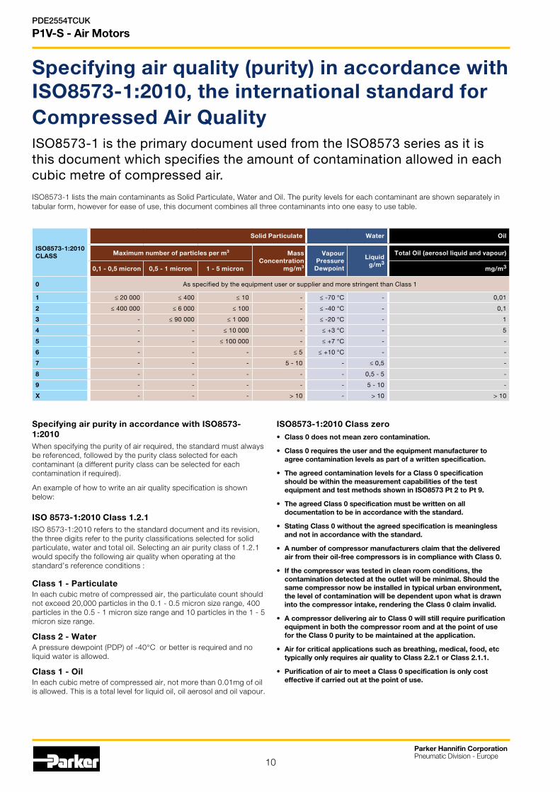
Specifying air quality (purity) in accordance with ISO8573-1:2010, the international standard for Compressed Air QualityISO8573-1 is the primary document used from the ISO8573 series as it is this document which specifies the amount of contamination allowed in each cubic metre of compressed air.
ISO8573-1 lists the main contaminants as Solid Particulate, Water and Oil. The purity levels for each contaminant are shown separately in tabular form, however for ease of use, this document combines all three contaminants into one easy to use table.
ISO8573-1:2010 CLASS
Solid Particulate Water Oil
Maximum number of particles per m3 MassConcentration
mg/m3
Vapour Pressure
Dewpoint
Liquid g/m3
Total Oil (aerosol liquid and vapour)
0,1 - 0,5 micron 0,5 - 1 micron 1 - 5 micron mg/m3
0 As specified by the equipment user or supplier and more stringent than Class 1
1 ≤ 20 000 ≤ 400 ≤ 10 - ≤ -70 °C - 0,01
2 ≤ 400 000 ≤ 6 000 ≤ 100 - ≤ -40 °C - 0,1
3 - ≤ 90 000 ≤ 1 000 - ≤ -20 °C - 1
4 - - ≤ 10 000 - ≤ +3 °C - 5
5 - - ≤ 100 000 - ≤ +7 °C - -
6 - - - ≤ 5 ≤ +10 °C - -
7 - - - 5 - 10 - ≤ 0,5 -
8 - - - - - 0,5 - 5 -
9 - - - - - 5 - 10 -
X - - - > 10 - > 10 > 10
Specifying air purity in accordance with ISO8573-1:2010When specifying the purity of air required, the standard must always be referenced, followed by the purity class selected for each contaminant (a different purity class can be selected for each contamination if required).
An example of how to write an air quality specification is shown below:
ISO 8573-1:2010 Class 1.2.1ISO 8573-1:2010 refers to the standard document and its revision, the three digits refer to the purity classifications selected for solid particulate, water and total oil. Selecting an air purity class of 1.2.1 would specify the following air quality when operating at the standard’s reference conditions :
Class 1 - ParticulateIn each cubic metre of compressed air, the particulate count should not exceed 20,000 particles in the 0.1 - 0.5 micron size range, 400 particles in the 0.5 - 1 micron size range and 10 particles in the 1 - 5 micron size range.
Class 2 - WaterA pressure dewpoint (PDP) of -40°C or better is required and no liquid water is allowed.
Class 1 - OilIn each cubic metre of compressed air, not more than 0.01mg of oil is allowed. This is a total level for liquid oil, oil aerosol and oil vapour.
ISO8573-1:2010 Class zero • Class 0 does not mean zero contamination.
• Class 0 requires the user and the equipment manufacturer to agree contamination levels as part of a written specification.
• The agreed contamination levels for a Class 0 specification should be within the measurement capabilities of the test equipment and test methods shown in ISO8573 Pt 2 to Pt 9.
• The agreed Class 0 specification must be written on all documentation to be in accordance with the standard.
• Stating Class 0 without the agreed specification is meaningless and not in accordance with the standard.
• A number of compressor manufacturers claim that the delivered air from their oil-free compressors is in compliance with Class 0.
• If the compressor was tested in clean room conditions, the contamination detected at the outlet will be minimal. Should the same compressor now be installed in typical urban environment, the level of contamination will be dependent upon what is drawn into the compressor intake, rendering the Class 0 claim invalid.
• A compressor delivering air to Class 0 will still require purification equipment in both the compressor room and at the point of use for the Class 0 purity to be maintained at the application.
• Air for critical applications such as breathing, medical, food, etc typically only requires air quality to Class 2.2.1 or Class 2.1.1.
• Purification of air to meet a Class 0 specification is only cost effective if carried out at the point of use.
11
Parker Hannifin CorporationPneumatic Division - Europe
PDE2554TCUK
P1V-S - Air Motors
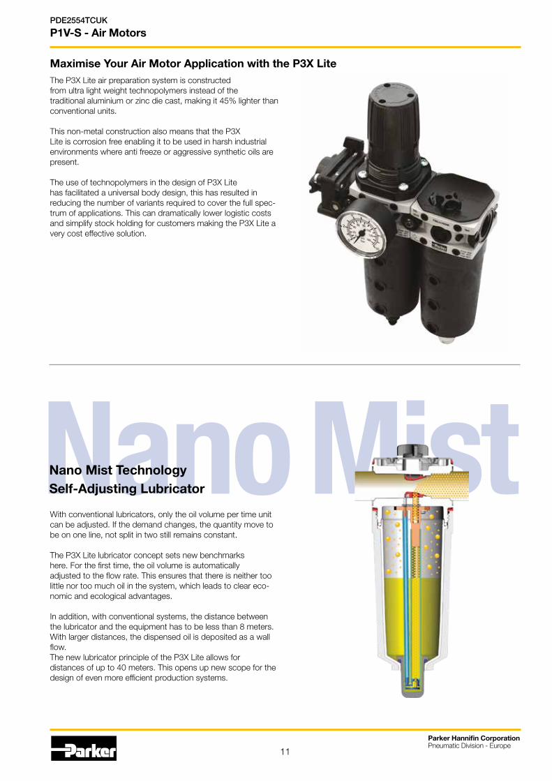
NanoMistNano Mist TechnologySelf-Adjusting Lubricator
Maximise Your Air Motor Application with the P3X Lite
With conventional lubricators, only the oil volume per time unit can be adjusted. If the demand changes, the quantity move to be on one line, not split in two still remains constant.
The P3X Lite lubricator concept sets new benchmarks here. For the first time, the oil volume is automatically adjusted to the flow rate. This ensures that there is neither too little nor too much oil in the system, which leads to clear eco-nomic and ecological advantages. In addition, with conventional systems, the distance between the lubricator and the equipment has to be less than 8 meters. With larger distances, the dispensed oil is deposited as a wall flow. The new lubricator principle of the P3X Lite allows for distances of up to 40 meters. This opens up new scope for the design of even more efficient production systems.
The P3X Lite air preparation system is constructedfrom ultra light weight technopolymers instead of the traditional aluminium or zinc die cast, making it 45% lighter than conventional units.
This non-metal construction also means that the P3X Lite is corrosion free enabling it to be used in harsh industrial environments where anti freeze or aggressive synthetic oils are present.
The use of technopolymers in the design of P3X Lite has facilitated a universal body design, this has resulted in reducing the number of variants required to cover the full spec-trum of applications. This can dramatically lower logistic costs and simplify stock holding for customers making the P3X Lite a very cost effective solution.
12
Parker Hannifin CorporationPneumatic Division - Europe
PDE2554TCUK
P1V-S - Stainless Steel Air Motors
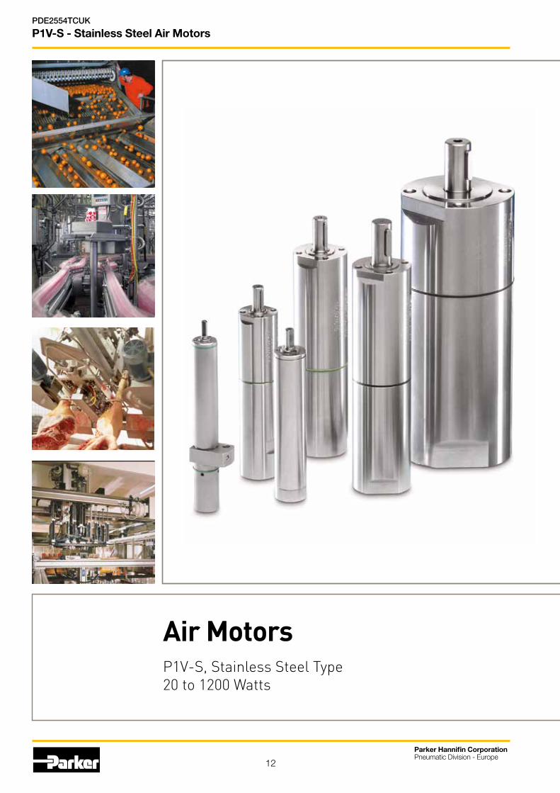
Air MotorsP1V-S, Stainless Steel Type20 to 1200 Watts
13
Parker Hannifin CorporationPneumatic Division - Europe
PDE2554TCUK
P1V-S - Stainless Steel Air Motors
Contents Page
Stainless Steel Air Motors P1V-S ................................................................. 15Choice of air motor ...................................................................................... 16Overview ..................................................................................................... 17Technical data ............................................................................................. 18Material specification ................................................................................... 18 Permitted shaft loadings .............................................................................. 19Order key .................................................................................................... 20Choice of vanes ........................................................................................... 20Reversible air motor 20 watts ..................................................................... 21Torque and power graphs ............................................................................ 21Dimensions .................................................................................................. 21Reversible air motor right direction 30 watts ................................................ 22Torque and power graphs ............................................................................ 22Dimensions .................................................................................................. 22Reversible air motor 80 watts ...................................................................... 23Torque and power graphs ............................................................................ 23Dimensions .................................................................................................. 23Reversible air motor 120 watts .................................................................... 24Torque and power graphs ............................................................................ 24Dimensions .................................................................................................. 25Reversible air motor 200 watts .................................................................... 26Torque and power graphs ............................................................................ 26Dimensions .................................................................................................. 27Reversible air motor 300 watts .................................................................... 28Torque and power graphs ............................................................................ 28Dimensions .................................................................................................. 29Reversible air motor 600 watts .................................................................... 30Torque and power graphs ............................................................................ 30Dimensions .................................................................................................. 31Reversible air motor 900 watts .................................................................... 32Torque and power graphs ............................................................................ 32Dimensions .................................................................................................. 33Reversible air motor 1200 watts .................................................................. 34Torque and power graphs ............................................................................ 34Dimensions .................................................................................................. 35
Stainless Steel Air Motors with brakes P1V-S ....................................... 36 - 45
High Torque Stainless Steel Air Motors P1V-S ....................................... 47 - 55
Mountings ................................................................................................... 56
Lubrication and service life ........................................................................... 57
Service kits ........................................................................................... 58 - 59
Introduction to the ATEX directive ......................................................... 60 - 64
14
Parker Hannifin CorporationPneumatic Division - Europe
PDE2554TCUK
P1V-S - Stainless Steel Air Motors
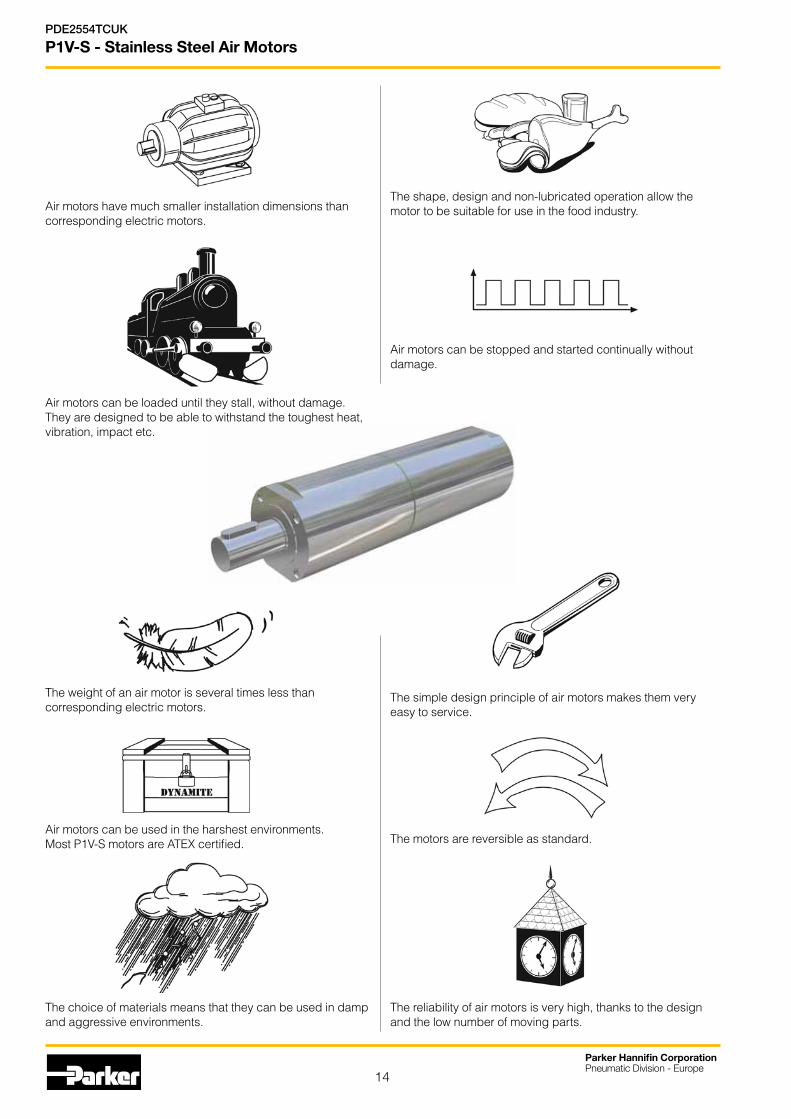
Air motors have much smaller installation dimensions than corresponding electric motors.
Air motors can be loaded until they stall, without damage. They are designed to be able to withstand the toughest heat, vibration, impact etc.
The weight of an air motor is several times less than corresponding electric motors.
Air motors can be used in the harshest environments. Most P1V-S motors are ATEX certified.
The shape, design and non-lubricated operation allow the motor to be suitable for use in the food industry.
Air motors can be stopped and started continually without damage.
The simple design principle of air motors makes them very easy to service.
The motors are reversible as standard.
The reliability of air motors is very high, thanks to the design and the low number of moving parts.
The choice of materials means that they can be used in damp and aggressive environments.
15
Parker Hannifin CorporationPneumatic Division - Europe
PDE2554TCUK
P1V-S - Stainless Steel Air Motors
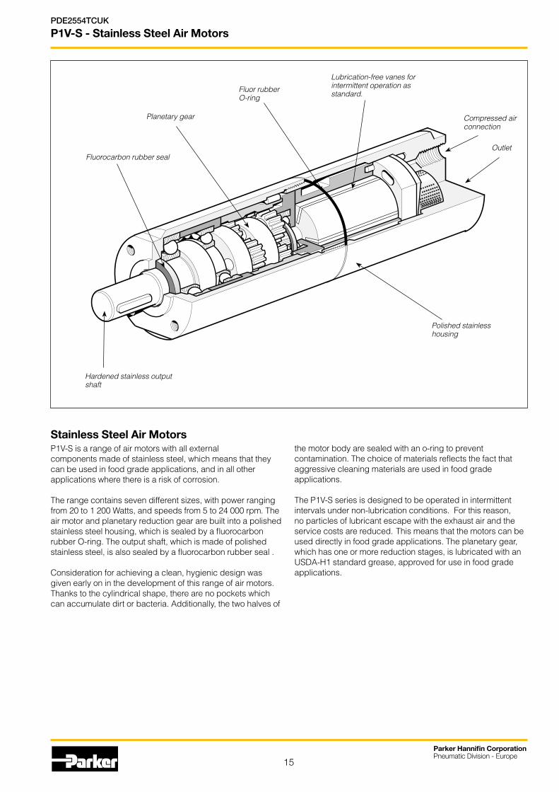
Stainless Steel Air MotorsP1V-S is a range of air motors with all external components made of stainless steel, which means that they can be used in food grade applications, and in all other applications where there is a risk of corrosion. The range contains seven different sizes, with power ranging from 20 to 1 200 Watts, and speeds from 5 to 24 000 rpm . The air motor and planetary reduction gear are built into a polished stainless steel housing, which is sealed by a fluorocarbon rubber O-ring. The output shaft, which is made of polished stainless steel, is also sealed by a fluorocarbon rubber seal . Consideration for achieving a clean, hygienic design was given early on in the development of this range of air motors. Thanks to the cylindrical shape, there are no pockets which can accumulate dirt or bacteria. Additionally, the two halves of
Fluorocarbon rubber seal
Planetary gear
Fluor rubber O-ring
Lubrication-free vanes for intermittent operation as standard.
Compressed air connection
Outlet
Polished stainless housing
Hardened stainless output shaft
the motor body are sealed with an o-ring to prevent contamination. The choice of materials reflects the fact that aggressive cleaning materials are used in food grade applications. The P1V-S series is designed to be operated in intermittent intervals under non-lubrication conditions. For this reason, no particles of lubricant escape with the exhaust air and the service costs are reduced. This means that the motors can be used directly in food grade applications. The planetary gear, which has one or more reduction stages, is lubricated with an USDA-H1 standard grease, approved for use in food grade applications.
16
Parker Hannifin CorporationPneumatic Division - Europe
PDE2554TCUK
P1V-S - Stainless Steel Air Motors
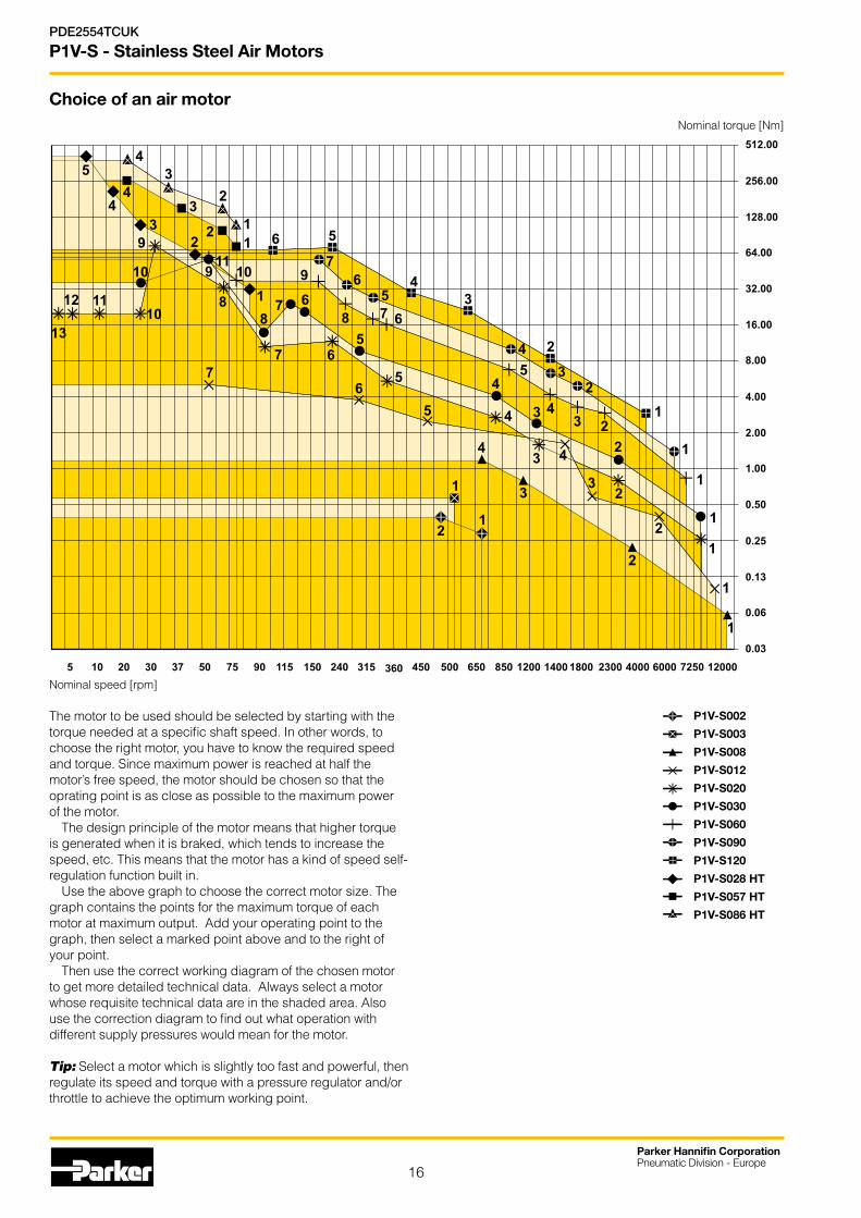
The motor to be used should be selected by starting with the torque needed at a specific shaft speed. In other words, to choose the right motor, you have to know the required speed and torque. Since maximum power is reached at half the motor’s free speed, the motor should be chosen so that the oprating point is as close as possible to the maximum power of the motor.
The design principle of the motor means that higher torque is generated when it is braked, which tends to increase the speed, etc. This means that the motor has a kind of speed self-regulation function built in.
Use the above graph to choose the correct motor size. The graph contains the points for the maximum torque of each motor at maximum output. Add your operating point to the graph, then select a marked point above and to the right of your point.
Then use the correct working diagram of the chosen motor to get more detailed technical data. Always select a motor whose requisite technical data are in the shaded area. Also use the correction diagram to find out what operation with different supply pressures would mean for the motor.
Tip: Select a motor which is slightly too fast and powerful, then regulate its speed and torque with a pressure regulator and/or throttle to achieve the optimum working point.
Choice of an air motorNominal torque [Nm]
Nominal speed [rpm]
P1V-S002
P1V-S003
P1V-S008
P1V-S012
P1V-S020
P1V-S030
P1V-S060
P1V-S090
P1V-S120
P1V-S028 HT
P1V-S057 HT
P1V-S086 HT
17
Parker Hannifin CorporationPneumatic Division - Europe
PDE2554TCUK
P1V-S - Stainless Steel Air Motors
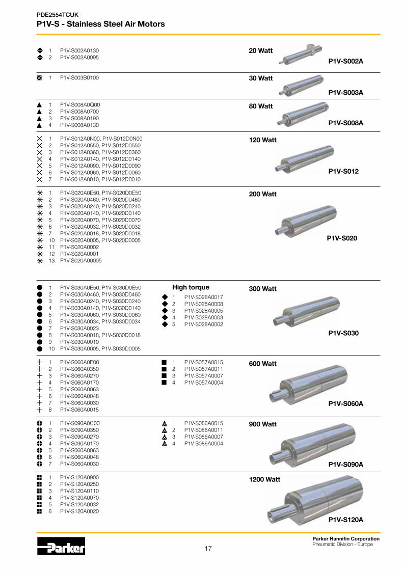
1 P1V-S002A01302 P1V-S002A0095
1 P1V-S003B0100
1 P1V-S008A0Q002 P1V-S008A07003 P1V-S008A01904 P1V-S008A0130 1 P1V-S012A0N00, P1V-S012D0N002 P1V-S012A0550, P1V-S012D05503 P1V-S012A0360, P1V-S012D03604 P1V-S012A0140, P1V-S012D01405 P1V-S012A0090, P1V-S012D00906 P1V-S012A0060, P1V-S012D00607 P1V-S012A0010, P1V-S012D0010 1 P1V-S020A0E50, P1V-S020D0E502 P1V-S020A0460, P1V-S020D04603 P1V-S020A0240, P1V-S020D02404 P1V-S020A0140, P1V-S020D01405 P1V-S020A0070, P1V-S020D00706 P1V-S020A0032, P1V-S020D00327 P1V-S020A0018, P1V-S020D001810 P1V-S020A0005, P1V-S020D000511 P1V-S020A000212 P1V-S020A000113 P1V-S020A00005
1 P1V-S030A0E50, P1V-S030D0E502 P1V-S030A0460, P1V-S030D04603 P1V-S030A0240, P1V-S030D02404 P1V-S030A0140, P1V-S030D01405 P1V-S030A0060, P1V-S030D00606 P1V-S030A0034, P1V-S030D00347 P1V-S030A00238 P1V-S030A0018, P1V-S030D00189 P1V-S030A001010 P1V-S030A0005, P1V-S030D0005 1 P1V-S060A0E002 P1V-S060A03503 P1V-S060A02704 P1V-S060A01705 P1V-S060A00636 P1V-S060A00487 P1V-S060A00308 P1V-S060A0015 1 P1V-S090A0C002 P1V-S090A03503 P1V-S090A02704 P1V-S090A01705 P1V-S060A00636 P1V-S060A00487 P1V-S060A0030
1 P1V-S120A09002 P1V-S120A02503 P1V-S120A01104 P1V-S120A00705 P1V-S120A00326 P1V-S120A0020
P1V-S002A
P1V-S008A
P1V-S012
P1V-S020
P1V-S030
P1V-S060A
P1V-S120A
20 Watt
80 Watt
120 Watt
200 Watt
300 Watt
600 Watt
1200 Watt
30 Watt
900 Watt
P1V-S003A
P1V-S090A
1 P1V-S057A00152 P1V-S057A00113 P1V-S057A00074 P1V-S057A0004
1 P1V-S086A00152 P1V-S086A00113 P1V-S086A00074 P1V-S086A0004
High torque
1 P1V-S028A0017 2 P1V-S028A00083 P1V-S028A00054 P1V-S028A00035 P1V-S028A0002
18
Parker Hannifin CorporationPneumatic Division - Europe
PDE2554TCUK
P1V-S - Stainless Steel Air Motors
Air motor size& type
P1V-S002
P1V-S003
P1V-S008
P1V-S012
P1V-S020
P1V-S030
P1V-S060
P1V-S090
P1V-S120
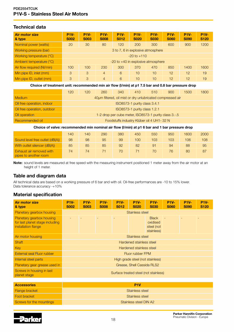
Nominal power (watts) 20 30 80 120 200 300 600 900 1200
Working pressure (bar) 3 to 7, 6 in explosive atmosphere
Working temperature (°C) -20 to +110
Ambient temperature (°C) -20 to +40 in explosive atmosphere
Air flow required (NI/min) 100 100 230 300 370 470 850 1400 1600
Min pipe ID, inlet (mm) 3 3 4 6 10 10 12 12 19
Min pipe ID, outlet (mm) 3 3 4 6 10 10 12 12 19
Choice of treatment unit: recommended min air flow (l/min) at p1 7.5 bar and 0.8 bar pressure drop
120 120 260 340 410 510 900 1500 1800
Medium 40µm filtered, oil mist or dry unlubricated compressed air
Oil free operation, indoor ISO8573-1 purity class 3.4.1
Oil free operation, outdoor ISO8573-1 purity class 1.2.1
Oil operation 1-2 drop per cube meter, ISO8573-1 purity class 3.-.5
Recommended oil Foodstuffs industry Klüber oil 4 UH1- 32 N
Choice of valve: recommended min nominal air flow (l/min) at p1 6 bar and 1 bar pressure drop
140 140 290 380 450 550 950 1600 2000
Sound level free outlet (dB(A)) 98 98 95 99 100 103 103 106 108
With outlet silencer (dB(A)) 85 85 85 92 82 91 94 88 95
Exhaust air removed with pipes to another room
74 74 71 70 71 70 76 80 87
Technical data
Note: sound levels are measured at free speed with the measuring instrument positioned 1 meter away from the air motor at an height of 1 meter.
Table and diagram dataAll technical data are based on a working pressure of 6 bar and with oil. Oil-free performances are -10 to 15% lower. Data tolerance accuracy -+10%
Material specification
Air motor size& type
P1V-S002
P1V-S003
P1V-S008
P1V-S012
P1V-S020
P1V-S030
P1V-S060
P1V-S090
P1V-S120
Planetary gearbox housing Stainless steel
Planetary gearbox housing for last planet stage including installation flange
- - - - Black oxidised steel (not stainless)
- - -
Air motor housing Stainless steel
Shaft Hardened stainless steel
Key Hardened stainless steel
External seal Fluor rubber Fluor rubber FPM
Internal steel parts High grade steel (not stainless)
Planetary gear grease used in Grease, Shell Cassida RLS2
Screws in housing in last planet stage
Surface treated steel (not stainless)
Accessories P1V
Flange bracket Stainless steel
Foot bracket Stainless steel
Screws for the mountings Stainless steel DIN A2
19
Parker Hannifin CorporationPneumatic Division - Europe
PDE2554TCUK
P1V-S - Stainless Steel Air Motors
rad
axFax
Frada
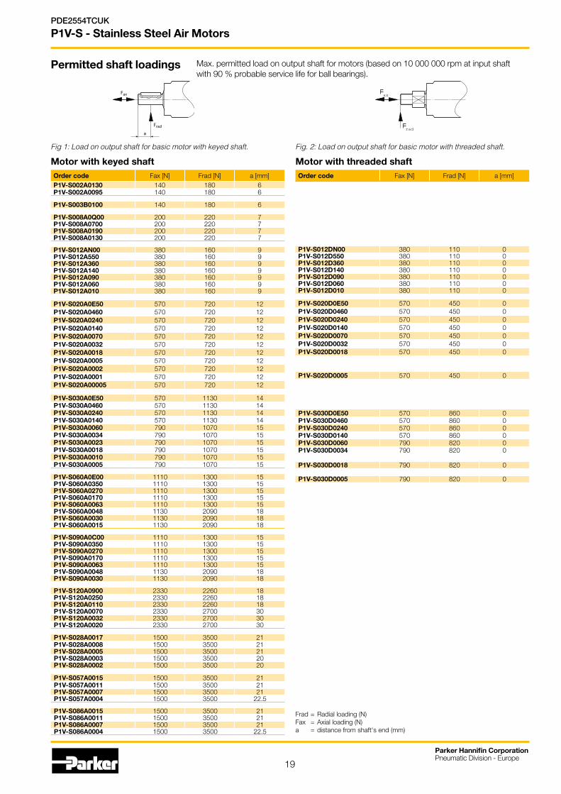
Max. permitted load on output shaft for motors (based on 10 000 000 rpm at input shaftwith 90 % probable service life for ball bearings).
Fig 1: Load on output shaft for basic motor with keyed shaft. Fig. 2: Load on output shaft for basic motor with threaded shaft.
Order code Fax [N] Frad [N] a [mm]P1V-S002A0130 140 180 6P1V-S002A0095 140 180 6
P1V-S003B0100 140 180 6
P1V-S008A0Q00 200 220 7P1V-S008A0700 200 220 7P1V-S008A0190 200 220 7P1V-S008A0130 200 220 7
P1V-S012AN00 380 160 9P1V-S012A550 380 160 9P1V-S012A360 380 160 9P1V-S012A140 380 160 9P1V-S012A090 380 160 9P1V-S012A060 380 160 9P1V-S012A010 380 160 9
P1V-S020A0E50 570 720 12P1V-S020A0460 570 720 12P1V-S020A0240 570 720 12P1V-S020A0140 570 720 12P1V-S020A0070 570 720 12P1V-S020A0032 570 720 12P1V-S020A0018 570 720 12P1V-S020A0005 570 720 12P1V-S020A0002 570 720 12P1V-S020A0001 570 720 12P1V-S020A00005 570 720 12
P1V-S030A0E50 570 1130 14P1V-S030A0460 570 1130 14P1V-S030A0240 570 1130 14P1V-S030A0140 570 1130 14P1V-S030A0060 790 1070 15P1V-S030A0034 790 1070 15P1V-S030A0023 790 1070 15P1V-S030A0018 790 1070 15P1V-S030A0010 790 1070 15P1V-S030A0005 790 1070 15
P1V-S060A0E00 1110 1300 15P1V-S060A0350 1110 1300 15P1V-S060A0270 1110 1300 15P1V-S060A0170 1110 1300 15P1V-S060A0063 1110 1300 15P1V-S060A0048 1130 2090 18P1V-S060A0030 1130 2090 18P1V-S060A0015 1130 2090 18
P1V-S090A0C00 1110 1300 15P1V-S090A0350 1110 1300 15P1V-S090A0270 1110 1300 15P1V-S090A0170 1110 1300 15P1V-S090A0063 1110 1300 15P1V-S090A0048 1130 2090 18P1V-S090A0030 1130 2090 18
P1V-S120A0900 2330 2260 18P1V-S120A0250 2330 2260 18P1V-S120A0110 2330 2260 18P1V-S120A0070 2330 2700 30P1V-S120A0032 2330 2700 30P1V-S120A0020 2330 2700 30
P1V-S028A0017 1500 3500 21P1V-S028A0008 1500 3500 21P1V-S028A0005 1500 3500 21P1V-S028A0003 1500 3500 20P1V-S028A0002 1500 3500 20
P1V-S057A0015 1500 3500 21P1V-S057A0011 1500 3500 21P1V-S057A0007 1500 3500 21P1V-S057A0004 1500 3500 22.5
P1V-S086A0015 1500 3500 21P1V-S086A0011 1500 3500 21P1V-S086A0007 1500 3500 21P1V-S086A0004 1500 3500 22.5
Motor with keyed shaft
Permitted shaft loadings
Order code Fax [N] Frad [N] a [mm]
P1V-S012DN00 380 110 0P1V-S012D550 380 110 0P1V-S012D360 380 110 0P1V-S012D140 380 110 0P1V-S012D090 380 110 0P1V-S012D060 380 110 0P1V-S012D010 380 110 0
P1V-S020D0E50 570 450 0P1V-S020D0460 570 450 0P1V-S020D0240 570 450 0P1V-S020D0140 570 450 0P1V-S020D0070 570 450 0P1V-S020D0032 570 450 0P1V-S020D0018 570 450 0
P1V-S020D0005 570 450 0
P1V-S030D0E50 570 860 0P1V-S030D0460 570 860 0P1V-S030D0240 570 860 0P1V-S030D0140 570 860 0P1V-S030D0060 790 820 0P1V-S030D0034 790 820 0
P1V-S030D0018 790 820 0
P1V-S030D0005 790 820 0
Motor with threaded shaft
Frad = Radial loading (N)Fax = Axial loading (N)a = distance from shaft's end (mm)
20
Parker Hannifin CorporationPneumatic Division - Europe
PDE2554TCUK
P1V-S - Stainless Steel Air Motors
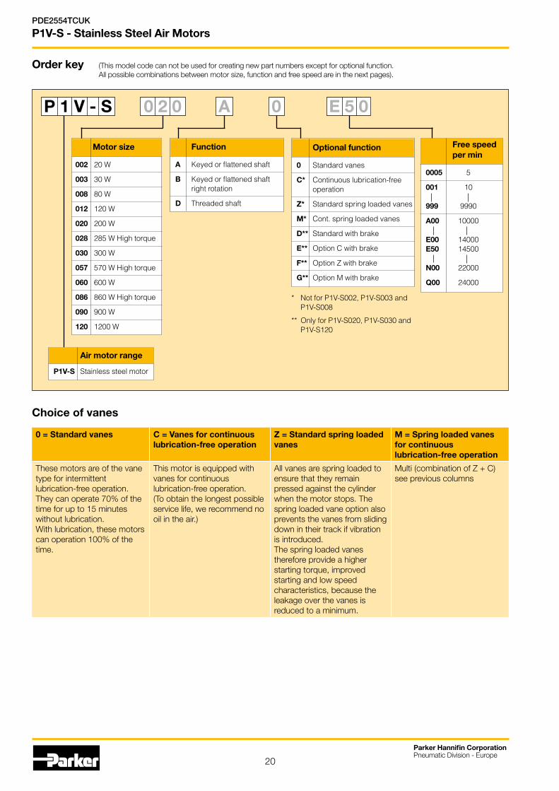
Order key (This model code can not be used for creating new part numbers except for optional function. All possible combinations between motor size, function and free speed are in the next pages).
Function
A Keyed or flattened shaft
B Keyed or flattened shaft right rotation
D Threaded shaft
Motor size
002 20 W
003 30 W
008 80 W
012 120 W
020 200 W
028 285 W High torque
030 300 W
057 570 W High torque
060 600 W
086 860 W High torque
090 900 W
120 1200 W
Optional function
0 Standard vanes
C* Continuous lubrication-free operation
Z* Standard spring loaded vanes
M* Cont. spring loaded vanes
D** Standard with brake
E** Option C with brake
F** Option Z with brake
G** Option M with brake
* Not for P1V-S002, P1V-S003 and P1V-S008
** Only for P1V-S020, P1V-S030 and P1V-S120
Free speed per min
0005 5
001 10 999 9990
A00 10000 E00 14000 E50 14500 N00 22000
Q00 24000
Air motor range
P1V-S Stainless steel motor
P 1 V - S 0 2 0 A 0 E 5 0
Choice of vanes
0 = Standard vanes C = Vanes for continuous lubrication-free operation
Z = Standard spring loaded vanes
M = Spring loaded vanes for continuous lubrication-free operation
These motors are of the vane type for intermittentlubrication-free operation.They can operate 70% of the time for up to 15 minuteswithout lubrication.With lubrication, these motors can operation 100% of the time.
This motor is equipped with vanes for continuouslubrication-free operation. (To obtain the longest possible service life, we recommend no oil in the air.)
All vanes are spring loaded to ensure that they remain pressed against the cylinder when the motor stops. The spring loaded vane option also prevents the vanes from sliding down in their track if vibration is introduced. The spring loaded vanes therefore provide a higher starting torque, improved starting and low speed characteristics, because the leakage over the vanes is reduced to a minimum.
Multi (combination of Z + C) see previous columns
21
Parker Hannifin CorporationPneumatic Division - Europe
PDE2554TCUK
P1V-S - Stainless Steel Air Motors 20 watts
400200 600 800 1000
5
10
15
20
0,2
0,4
0,6
0,8M
P
P1V-S002A0095M, torque [Nm] P, power [W]
P1V-S002A0130M, torque [Nm] P, power [W]
600300 900 1200 1500
5
10
15
20
0,2
0,4
0,6M
P
n, speed [rpm] n, speed [rpm]
Possible working range of motor.
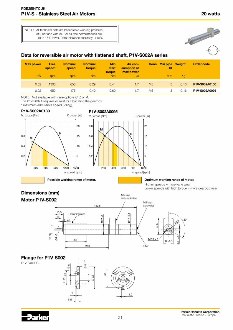
NOTE! All technical data are based on a working pressure of 6 bar and with oil. For oil-free performances are -10 to 15% lower. Data tolerance accuracy -+10%
Dimensions (mm)Motor P1V-S002
132,5
13,5
10
70,5
35Ø8
e8
Ø4
k6
1 -0,1
Ø17
e8
Ø17
-0,
1
17 -0,1M2,5 x 5
27,5 Ø12
120°
3,5
-0,1
M5 Inlet anticlockwise
M5 Inlet clockwise
Clamping area
Outlet
Optimum working range of motor.
Higher speeds = more vane wearLower speeds with high torque = more gearbox wear
Flange for P1V-S002P1V-S4002B
Data for reversible air motor with flattened shaft, P1V-S002A series
Max power Free Nominal Nominal Min Air con- Conn. Min pipe Weight Order code speed* speed torque start sumption at ID torque max power kW rpm rpm Nm Nm l/s mm Kg
0.02 1300 650 0.29 0.44 1.7 M5 3 0.16 P1V-S002A0130
0.02 950 475 0.40 0.60 1.7 M5 3 0.16 P1V-S002A0095
NOTE! Not available with vane options C. Z or M.The P1V-S002A requires oil mist for lubricating the gearbox.* maximum admissible speed (idling)
22
Parker Hannifin CorporationPneumatic Division - Europe
PDE2554TCUK
P1V-S - Stainless Steel Air Motors
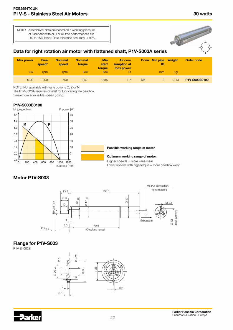
Motor P1V-S003
(Chucking range)
M5 (Air connection right rotation)
30 watts
Exhaust air
(Hol
e pa
ttern
)
Flange for P1V-S003P1V-S4002B
Data for right rotation air motor with flattened shaft, P1V-S003A series
Max power Free Nominal Nominal Min Air con- Conn. Min pipe Weight Order code speed* speed torque start sumption at ID torque max power kW rpm rpm Nm Nm l/s mm Kg
0.03 1000 500 0,57 0,85 1,7 M5 3 0,13 P1V-S003B0100
NOTE! Not available with vane options C, Z or M.The P1V-S003A requires oil mist for lubricating the gearbox.* maximum admissible speed (idling)
NOTE! All technical data are based on a working pressure of 6 bar and with oil. For oil-free performances are -10 to 15% lower. Data tolerance accuracy -+10%
P1V-S003B0100M, torque [Nm] P, power [W]
n, speed [rpm]
Possible working range of motor.
Optimum working range of motor.
Higher speeds = more vane wearLower speeds with high torque = more gearbox wear
23
Parker Hannifin CorporationPneumatic Division - Europe
PDE2554TCUK
P1V-S - Stainless Steel Air Motors
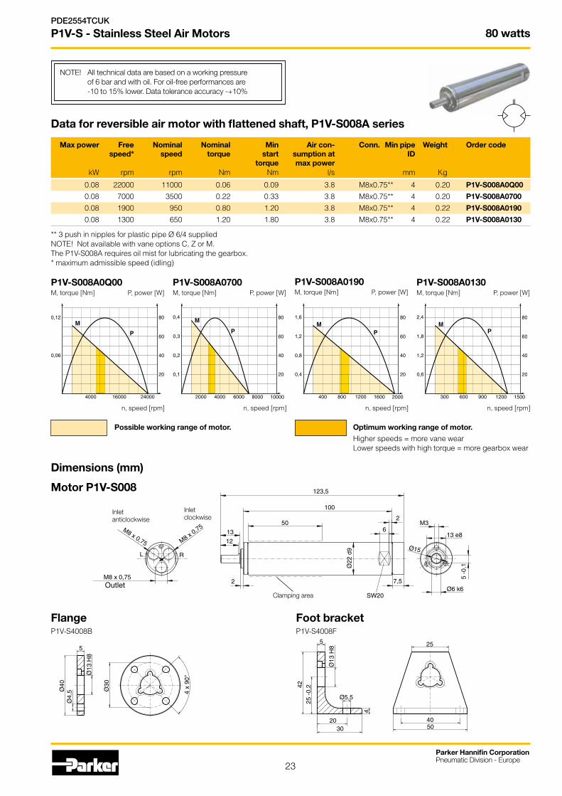
Data for reversible air motor with flattened shaft, P1V-S008A series
Max power Free Nominal Nominal Min Air con- Conn. Min pipe Weight Order code speed* speed torque start sumption at ID torque max power kW rpm rpm Nm Nm l/s mm Kg
0.08 22000 11000 0.06 0.09 3.8 M8x0.75** 4 0.20 P1V-S008A0Q00
0.08 7000 3500 0.22 0.33 3.8 M8x0.75** 4 0.20 P1V-S008A0700
0.08 1900 950 0.80 1.20 3.8 M8x0.75** 4 0.22 P1V-S008A0190
0.08 1300 650 1.20 1.80 3.8 M8x0.75** 4 0.22 P1V-S008A0130
** 3 push in nipples for plastic pipe Ø 6/4 suppliedNOTE! Not available with vane options C, Z or M.The P1V-S008A requires oil mist for lubricating the gearbox.* maximum admissible speed (idling)
P1V-S008A0700M, torque [Nm] P, power [W]
P1V-S008A0Q00M, torque [Nm] P, power [W]
P1V-S008A0190M, torque [Nm] P, power [W]
P1V-S008A0130M, torque [Nm] P, power [W]
2000 4000 6000 8000 10000
20
40
60
80
0,1
0,2
0,3
0,4 M
P
4000 16000 24000
20
40
60
80
0,06
0,12M
P
400 800 1200 1600 2000
20
40
60
80
0,4
0,8
1,2
1,6
MP
300 600 900 1200 1500
20
40
60
80
0,6
1,2
1,8
2,4
MP
n, speed [rpm]
80 watts
NOTE! All technical data are based on a working pressure of 6 bar and with oil. For oil-free performances are -10 to 15% lower. Data tolerance accuracy -+10%
n, speed [rpm] n, speed [rpm] n, speed [rpm]
Possible working range of motor. Optimum working range of motor.
Higher speeds = more vane wearLower speeds with high torque = more gearbox wear
Dimensions (mm)
Motor P1V-S008
FlangeP1V-S4008B
Foot bracketP1V-S4008F
Ø40
5
Ø4,
5
Ø13
H8
Ø30
4 x
90°
5
4225
-0,
2
Ø13
H8
2030
Ø5,5
4
4050
25
M8 x 0,75
M8 x 0,75 M8 x 0,75
L R
13
12
2
50
100
123,5
6
2
7,5
Ø22
d9
SW20
M3
13 e8
Ø6 k6
Ø15
5 -0
,1
Clamping area
Inlet anticlockwise
Inlet clockwise
Outlet
24
Parker Hannifin CorporationPneumatic Division - Europe
PDE2554TCUK
P1V-S - Stainless Steel Air Motors
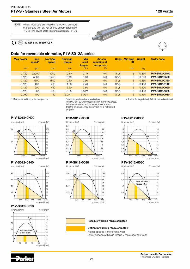
II2 GD c IIC T6 (80 °C) X
120 watts
P1V-S012•0550 P1V-S012•0360
P1V-S012•0140 P1V-S012•0090 P1V-S012•0060
P1V-S012•0010
P1V-S012•0N00
2000 4000 6000
15
45
75
105
30
60
90
120
0,1
0,2
0,3
0,4
0,9
0,5
0,6
0,7
0,8M
P
1600800 2400 3200 4000
15
45
75
105
30
60
90
120
0,2
0,4
0,6
0,8
1,0
1,2
1,4
1,6
MP
600300 900 1200 1500
15
45
75
105
30
60
90
120
1,0
2,0
3,0
4,0
M P
400200 600 800 1000
15
45
75
105
30
60
90
120
1,25
2,50
3,75
5,00M
P
300150 450 600 750
15
45
75
105
30
60
90
120
2,0
4,0
6,0
8,0
M P
5025 75 100 125
15
45
75
105
30
60
90
120
5
10
15
20M
P
4000 16000 24000
15
45
75
105
30
60
90
120
0,1
0,2M
P
Max permitted torque 5 Nm
Possible working range of motor.
Optimum working range of motor.
Higher speeds = more vane wearLower speeds with high torque = more gearbox wear
M, torque [Nm] P, power [W]
n, speed [rpm]
M, torque [Nm] P, power [W]
n, speed [rpm]
M, torque [Nm] P, power [W]
n, speed [rpm]
Max permitted torque 5 Nm
M, torque [Nm] P, power [W]
n, speed [rpm]
M, torque [Nm] P, power [W]
n, speed [rpm]
M, torque [Nm] P, power [W]
n, speed [rpm]
M, torque [Nm] P, power [W]
n, speed [rpm]
Data for reversible air motor, P1V-S012A series Max power Free Nominal Nominal Min Air con- Conn. Min pipe Weight Order code speed* speed torque start sumption at ID torque max power kW rpm rpm Nm Nm l/s mm Kg
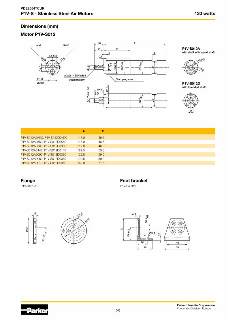
0.120 22000 11000 0.10 0.15 5.0 G1/8 6 0.350 P1V-S012•0N00 0.120 5500 2750 0.40 0.60 5.0 G1/8 6 0.350 P1V-S012•0550 0.120 3600 1800 0.60 0.90 5.0 G1/8 6 0.350 P1V-S012•0360 0.120 1400 700 1.60 2.40 5.0 G1/8 6 0.400 P1V-S012•0140 0.120 900 450 2.50 3.80 5.0 G1/8 6 0.400 P1V-S012•0090 0.120 600 300 3.80 5.00** 5.0 G1/8 6 0.400 P1V-S012•0060 0.090 100 50 5.00** 5.00** 5.0 G1/8 6 0.450 P1V-S012•0010
NOTE! All technical data are based on a working pressure of 6 bar and with oil. For oil-free performances are -10 to 15% lower. Data tolerance accuracy -+10%
** Max permitted torque for the gearbox * maximum admissible speed (idling)The P1V-S012D with threaded shaft may be reversed, but when operated anticlockwise, there is a risk that the driven unit may disconnect if it is not locked properly.
• A letter for keyed shaft, D for threaded end shaft
25
Parker Hannifin CorporationPneumatic Division - Europe
PDE2554TCUK
P1V-S - Stainless Steel Air Motors 120 watts
Dimensions (mm)
Motor P1V-S012
Ø4,5
Ø40
Ø13
H8
5
Ø50
40
50
Ø13
H84,5
42
-0,2
25
Ø5,5
4,5
20
30
OutletStainless key Clamping area
InletInletP1V-S012Awith shaft with keyed shaft
P1V-S012Dwith threaded shaft
M4x4,5
Ø21L R
6,8 6,8
47,
9
G1/8 G1/81//
G1/8/
Ø13
e8
SW
24
Ø27
e8
Ø27
d977
24
8
A
0,84
17 B
A2x2x14 DIN 6885
Ø8
k65/
16"-
24 U
NF
9,519,5 Ø
12,5
11
18
M4x4,5
Ø21L R
6,8 6,8
47,
9
G1/8 G1/81//
G1/8/Ø
13e8
SW
24
Ø27
e8
Ø27
d977
24
8
A
0,84
17 B
A2x2x14 DIN 6885
Ø8
k65/
16"-
24 U
NF
9,519,5 Ø
12,5
11
18
A B
P1V-S012A0N00, P1V-S012D0N00 117.0 46.5P1V-S012A0550. P1V-S012D0550 117.0 46.5P1V-S012A0360. P1V-S012D0360 117.0 46.5P1V-S012A0140. P1V-S012D0140 129.5 59.0P1V-S012A0090. P1V-S012D0090 129.5 59.0P1V-S012A0060. P1V-S012D0060 129.5 59.0P1V-S012A0010. P1V-S012D0010 142.0 71.5
FlangeP1V-S4012B
Foot bracketP1V-S4012F
26
Parker Hannifin CorporationPneumatic Division - Europe
PDE2554TCUK
P1V-S - Stainless Steel Air Motors 200 watts
NOTE! All technical data are based on a working pressure of 6 bar and with oil. For oil-free performances are -10 to 15% lower. Data tolerance accuracy -+10%
60003000 9000 12000 15000
25
75
125
175
50
100
150
200
0,15
0,30
0,45
0,60
M P
20001000 3000 4000 5000
25
75
125
175
50
100
150
200
0,4
0,8
1,2
1,6M
P
1000500 1500 2000 2500
25
75
125
175
50
100
150
200
0,75
1,50
2,25
3,00
M P
600300 900 1200 1500
25
75
125
175
50
100
150
200
1,5
3,0
4,5
6,0
M P
300150 450 600 750
25
75
125
175
50
100
150
200
3
6
9
12
M P
15075 225 300 375
25
75
125
175
50
100
150
200
6
12
18
24M
P
40 6020 80 100 140 160 200120 180
2,5
5,0
7,5
10,0
12,5
15,0
17,5
20,0
M
P
25
75
125
175
50
100
150
200
2010 30 40 50
25
75
125
175
50
100
150
200
20
40
60
80 M
P
Max permitted torque 20 Nm
2 4 6 8 10 12 14 16 18 20
25
75
125
175
50
100
150
200
20
40
60
80M
P
Max permitted torque 20 Nm
1P1V-S020A0001
P1V-S020A000051
2
2
3
3
4
4
5
5
6 7 8 9 10
30
90
150
60
120
180
20
40
60
MP
Max permitted torque 20 Nm
M, torque [Nm] P, power [W]
n, speed [rpm]
M, torque [Nm] P, power [W]
n, speed [rpm]
M, torque [Nm] P, power [W]
n, speed [rpm]
M, torque [Nm] P, power [W]
n, speed [rpm] n, speed [rpm]
M, torque [Nm] P, power [W]
n, speed [rpm]
M, torque [Nm] P, power [W]
n, speed [rpm]
M, torque [Nm] P, power [W]
n, speed [rpm]
M, torque [Nm] P, power [W]
n, speed [rpm]
M, torque [Nm] P, power [W]
n, speed [rpm]
P1V-S020•0E50 P1V-S020•0460 P1V-S020•0240 P1V-S020•0140
P1V-S020•0070 P1V-S020•0018 P1V-S020•0005
P1V-S020A0002 P1V-S020A0001 & P1V-S020A00005
P1V-S020•0032M, torque [Nm] P, power [W]
II2 GD c IIC T6 (80 °C) X
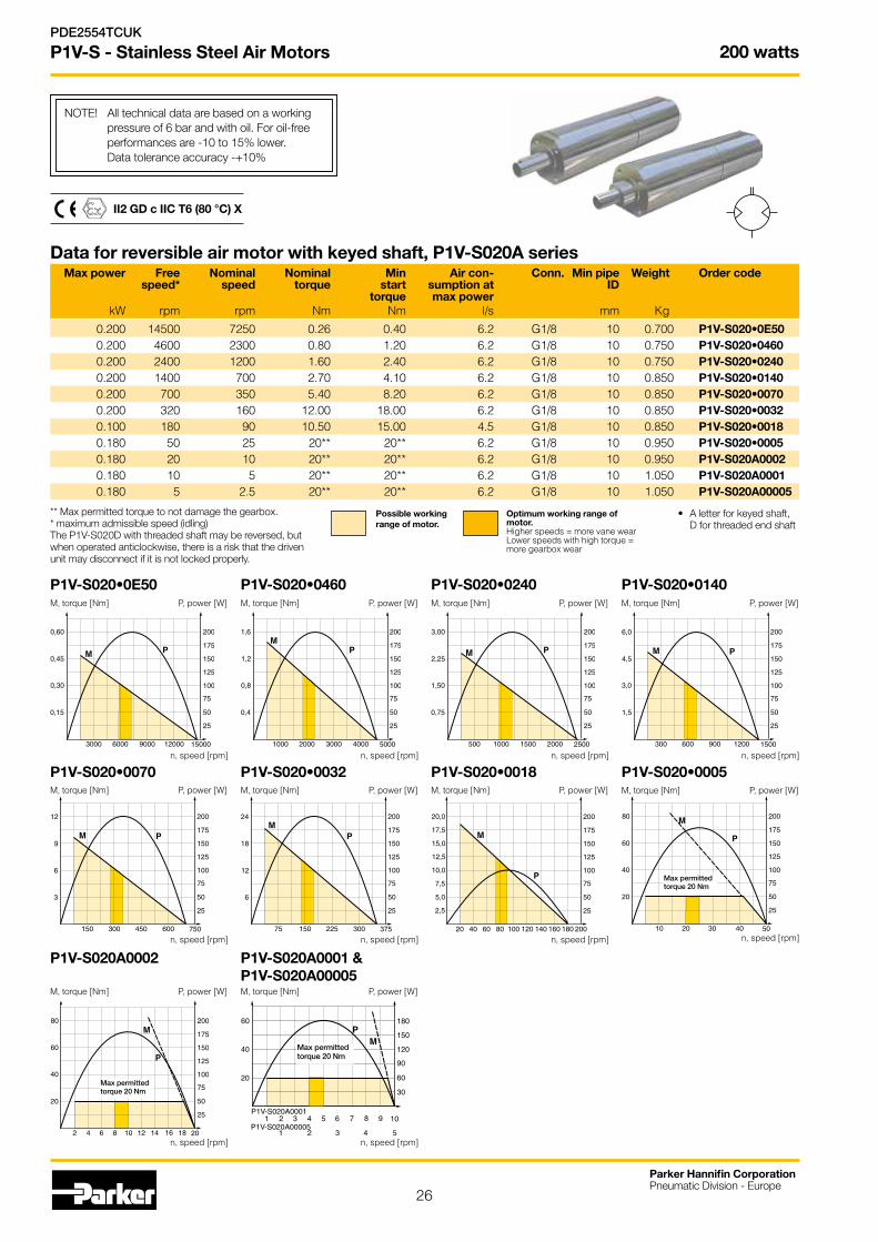
Data for reversible air motor with keyed shaft, P1V-S020A series Max power Free Nominal Nominal Min Air con- Conn. Min pipe Weight Order code speed* speed torque start sumption at ID torque max power kW rpm rpm Nm Nm l/s mm Kg
0.200 14500 7250 0.26 0.40 6.2 G1/8 10 0.700 P1V-S020•0E50 0.200 4600 2300 0.80 1.20 6.2 G1/8 10 0.750 P1V-S020•0460 0.200 2400 1200 1.60 2.40 6.2 G1/8 10 0.750 P1V-S020•0240 0.200 1400 700 2.70 4.10 6.2 G1/8 10 0.850 P1V-S020•0140 0.200 700 350 5.40 8.20 6.2 G1/8 10 0.850 P1V-S020•0070 0.200 320 160 12.00 18.00 6.2 G1/8 10 0.850 P1V-S020•0032 0.100 180 90 10.50 15.00 4.5 G1/8 10 0.850 P1V-S020•0018 0.180 50 25 20** 20** 6.2 G1/8 10 0.950 P1V-S020•0005 0.180 20 10 20** 20** 6.2 G1/8 10 0.950 P1V-S020A0002 0.180 10 5 20** 20** 6.2 G1/8 10 1.050 P1V-S020A0001 0.180 5 2.5 20** 20** 6.2 G1/8 10 1.050 P1V-S020A00005
Possible working range of motor.
Optimum working range of motor.Higher speeds = more vane wearLower speeds with high torque = more gearbox wear
** Max permitted torque to not damage the gearbox.* maximum admissible speed (idling)The P1V-S020D with threaded shaft may be reversed, but when operated anticlockwise, there is a risk that the driven unit may disconnect if it is not locked properly.
• A letter for keyed shaft, D for threaded end shaft
27
Parker Hannifin CorporationPneumatic Division - Europe
PDE2554TCUK
P1V-S - Stainless Steel Air Motors 200 watts
Motor P1V-S020
19
7
8
G1/8 G1/8
G1/4
M4x4
Ø30Ø20
e8
SW
34
Ø38
e8
Ø38
d9
34
8
A
0,885
B
A3x3x18 DIN 6885
23
Ø10
k63/
8"-2
4 U
NF
26
Ø16
,5
15
14
24
Clamping area
InletInlet
Outlet
Stainless key
P1V-S020Awith shaft with keyed shaft
P1V-S020Dwith threaded shaft
Dimensions (mm)
5,8
5
Ø20e8
Ø20H8
Ø5,5
Ø50
Ø60
Ø20H8
4,5
-0,2
30 Ø6,6 4,5
3020
5545
47
A B
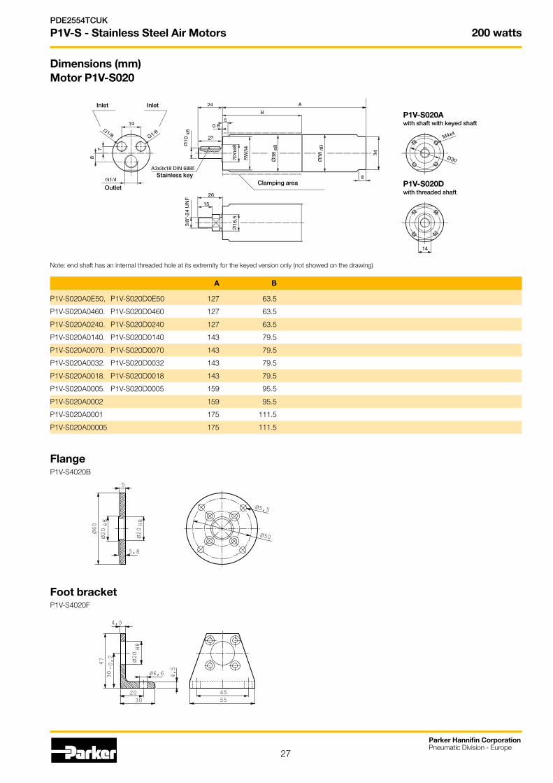
P1V-S020A0E50, P1V-S020D0E50 127 63.5
P1V-S020A0460. P1V-S020D0460 127 63.5
P1V-S020A0240. P1V-S020D0240 127 63.5
P1V-S020A0140. P1V-S020D0140 143 79.5
P1V-S020A0070. P1V-S020D0070 143 79.5
P1V-S020A0032. P1V-S020D0032 143 79.5
P1V-S020A0018. P1V-S020D0018 143 79.5
P1V-S020A0005. P1V-S020D0005 159 95.5
P1V-S020A0002 159 95.5
P1V-S020A0001 175 111.5
P1V-S020A00005 175 111.5
FlangeP1V-S4020B
Foot bracketP1V-S4020F
Note: end shaft has an internal threaded hole at its extremity for the keyed version only (not showed on the drawing)
28
Parker Hannifin CorporationPneumatic Division - Europe
PDE2554TCUK
P1V-S - Stainless Steel Air Motors 300 watts
M, torque [Nm] P, power [W]
n, speed [rpm]
M, torque [Nm] P, power [W]
n, speed [rpm]
M, torque [Nm] P, power [W]
n, speed [rpm]
M, torque [Nm] P, power [W]
n, speed [rpm]
M, torque [Nm] P, power [W]
n, speed [rpm]
M, torque [Nm] P, power [W]
n, speed [rpm]
M, torque [Nm] P, power [W]
n, speed [rpm]
M, torque [Nm] P, power [W]
n, speed [rpm]
M, torque [Nm] P, power [W]
n, speed [rpm]
M, torque [Nm] P, power [W]
n, speed [rpm]
60003000 9000 12000 15000
300
100
200
0,2
0,4
0,6
0,8M P
300
100
200
0,6
1,2
1,8
2,4M P
20001000 3000 4000 5000
300
100
200
1,0
2,0
3,0
4,0M P
1000500 1500 2000 2500
300
100
200
2,0
4,0
6,0
8,0M P
600300 900 1200 1500
300
100
200
5
10
15
20M
P
300150 450 600 750
300
100
200
10
20
30
40M P
100 300200 40 6020 80 100 140 160 200120 180
3
6
9
12
15
18
21
24M
P
300
100
200
300
100
200
36
72
108
144M
P
2010 30 40 50
Max permitted torque 36 Nm
300
100
200
20
40
60
80
M P
100 300200
300
100
200
30
60
90
120M P
20 10040 60 80
Possible working range of motor.
Optimum working range of motor.
Higher speeds = more vane wearLower speeds with high torque = more gearbox wear
P1V-S030•0E50 P1V-S030•0460 P1V-S030•0240 P1V-S030•0140
P1V-S030•0060 P1V-S030•0034 P1V-S030•0018
P1V-S030A0010 P1V-S030•0005
P1V-S030A0023
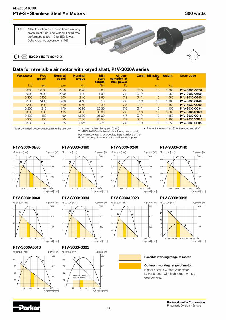
II2 GD c IIC T6 (80 °C) X
NOTE! All technical data are based on a working pressure of 6 bar and with oil. For oil-free performances are -10 to 15% lower. Data tolerance accuracy -+10%
Data for reversible air motor with keyed shaft, P1V-S030A series Max power Free Nominal Nominal Min Air con- Conn. Min pipe Weight Order code speed* speed torque start sumption at ID torque max power kW rpm rpm Nm Nm l/s mm Kg
0.300 14500 7250 0.40 0.60 7.8 G1/4 10 1.000 P1V-S030•0E50 0.300 4600 2300 1.20 1.90 7.8 G1/4 10 1.050 P1V-S030•0460 0.300 2400 1200 2.40 3.60 7.8 G1/4 10 1.050 P1V-S030•0240 0.300 1400 700 4.10 6.10 7.8 G1/4 10 1.100 P1V-S030•0140 0.300 600 300 9.60 14.30 7.8 G1/4 10 1.150 P1V-S030•0060 0.300 340 170 16.90 25.30 7.8 G1/4 10 1.150 P1V-S030•0034 0.300 230 115 24.00 36.00 7.8 G1/4 10 3.300 P1V-S030A0023 0.130 180 90 13.80 21.00 4.7 G1/4 10 1.150 P1V-S030•0018 0.300 100 50 57.00 85.50 7.8 G1/4 10 3.300 P1V-S030A0010 0.280 50 25 36** 36** 7.8 G1/4 10 1.250 P1V-S030•0005
** Max permitted torque to not damage the gearbox. * maximum admissible speed (idling)The P1V-S030D with threaded shaft may be reversed, but when operated anticlockwise, there is a risk that the driven unit may disconnect if it is not locked properly.
• A letter for keyed shaft, D for threaded end shaft
29
Parker Hannifin CorporationPneumatic Division - Europe
PDE2554TCUK
P1V-S - Stainless Steel Air Motors
Motor P1V-S030
Foot bracket for motorsP1V-S030A0023 and P1V-S030A0010P1V-S4020C
20
6,5
11
G1/4 G1/4
G1/4
36
L R Ø24
e8
SW
36
Ø42
d9
A B
0,85
C
F
D
ØE
k6
10
Ø42
d9
M5x
5,5
Ø34
Ø16
,5
27
15
3/8"
-24
UN
F
14
Inlet Inlet
Outlet
Stainless keyClamping area
P1V-S030Awith shaft with keyed shaft
P1V-S030Dwith threaded shaft
Ø5,5
Ø55
6,8
6
Ø24e8
Ø24H8
Ø21
Ø65
6050
Ø24H8
4,5-0,2
30 Ø6,6 4,5
3020
48
8535,550,5
Ø11
(9,5)
(9,5
)
Ø74
110
70
120
5x45
°
Black oxidised steel
P1V-S030A0023P1V-S030A0010
300 watts
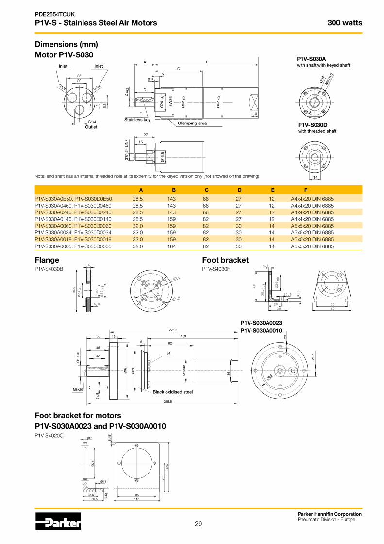
Dimensions (mm)
FlangeP1V-S4030B
Foot bracketP1V-S4030F
A B C D E F
P1V-S030A0E50, P1V-S030D0E50 28.5 143 66 27 12 A4x4x20 DIN 6885P1V-S030A0460. P1V-S030D0460 28.5 143 66 27 12 A4x4x20 DIN 6885P1V-S030A0240. P1V-S030D0240 28.5 143 66 27 12 A4x4x20 DIN 6885P1V-S030A0140. P1V-S030D0140 28.5 159 82 27 12 A4x4x20 DIN 6885P1V-S030A0060. P1V-S030D0060 32.0 159 82 30 14 A5x5x20 DIN 6885P1V-S030A0034. P1V-S030D0034 32.0 159 82 30 14 A5x5x20 DIN 6885P1V-S030A0018. P1V-S030D0018 32.0 159 82 30 14 A5x5x20 DIN 6885P1V-S030A0005. P1V-S030D0005 32.0 164 82 30 14 A5x5x20 DIN 6885
Note: end shaft has an internal threaded hole at its extremity for the keyed version only (not showed on the drawing)
30
Parker Hannifin CorporationPneumatic Division - Europe
PDE2554TCUK
P1V-S - Stainless Steel Air Motors 600 watts
600
200
400
0,4
0,8
1,2
1,6M P
3200 6400 9600 12800 16000
M, torque [Nm] P, power [W]
n, speed [rpm]
M, torque [Nm] P, power [W]
n, speed [rpm]
M, torque [Nm] P, power [W]
n, speed [rpm]
M, torque [Nm] P, power [W]
n, speed [rpm]
600
200
400
2,0
4,0
6,0
8,0M P
1000 2000 3000
M, torque [Nm] P, power [W]
n, speed [rpm]
P1V-S060A0270
600
200
400
4
8
12
16
M
P
600 1200 1800
M, torque [Nm] P, power [W]
n, speed [rpm]
P1V-S060A0170
600
200
400
10
20
30
40 MP
100 200 500300 400
M, torque [Nm] P, power [W]
n, speed [rpm]
P1V-S060A0048
600
200
400
20
40
60
80
MP
100 200 300
M, torque [Nm] P, power [W]
n, speed [rpm]
P1V-S060A0030
P1V-S060A0E00 P1V-S060A0350
P1V-S060A0063 P1V-S060A0015
II2 GD c IIC T6 (80 °C) X
Possible working range of motor.
Optimum working range of motor.
Higher speeds = more vane wearLower speeds with high torque = more gearbox wear
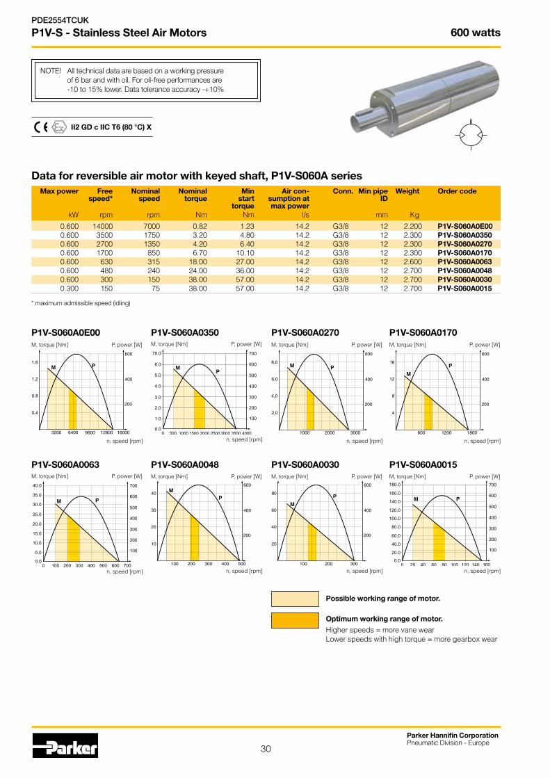
NOTE! All technical data are based on a working pressure of 6 bar and with oil. For oil-free performances are -10 to 15% lower. Data tolerance accuracy -+10%
Data for reversible air motor with keyed shaft, P1V-S060A series Max power Free Nominal Nominal Min Air con- Conn. Min pipe Weight Order code speed* speed torque start sumption at ID torque max power kW rpm rpm Nm Nm l/s mm Kg
0.600 14000 7000 0.82 1.23 14.2 G3/8 12 2.200 P1V-S060A0E00 0.600 3500 1750 3.20 4.80 14.2 G3/8 12 2.300 P1V-S060A0350 0.600 2700 1350 4.20 6.40 14.2 G3/8 12 2.300 P1V-S060A0270 0.600 1700 850 6.70 10.10 14.2 G3/8 12 2.300 P1V-S060A0170 0.600 630 315 18.00 27.00 14.2 G3/8 12 2.600 P1V-S060A0063 0.600 480 240 24.00 36.00 14.2 G3/8 12 2.700 P1V-S060A0048 0.600 300 150 38.00 57.00 14.2 G3/8 12 2.700 P1V-S060A0030 0.300 150 75 38.00 57.00 14.2 G3/8 12 2.700 P1V-S060A0015
* maximum admissible speed (idling)
31
Parker Hannifin CorporationPneumatic Division - Europe
PDE2554TCUK
P1V-S - Stainless Steel Air Motors 600 watts
14
G3/8 G3/8
G1/2
11,5
50
Ø35e8
SW50
Ø56d10
A
B
8
C
F
ØEk6
10
Ø56e8
1
D
Ø48
M6x7
24
Ø70
Ø6,6
8,5
1,5 Ø35
H8
7,5
Ø32
Ø35
Ø85
e8-1
0,5 x 45
Inlet Inlet
Outlet
Stainless keyClamping area
85
70
50
Ø35
H8
5,5
-0,2
40
6,6
5,5
50 -1
25
70 62
-1
Motor P1V-S060
FlangeP1V-S4060B
Foot bracketP1V-S4060F
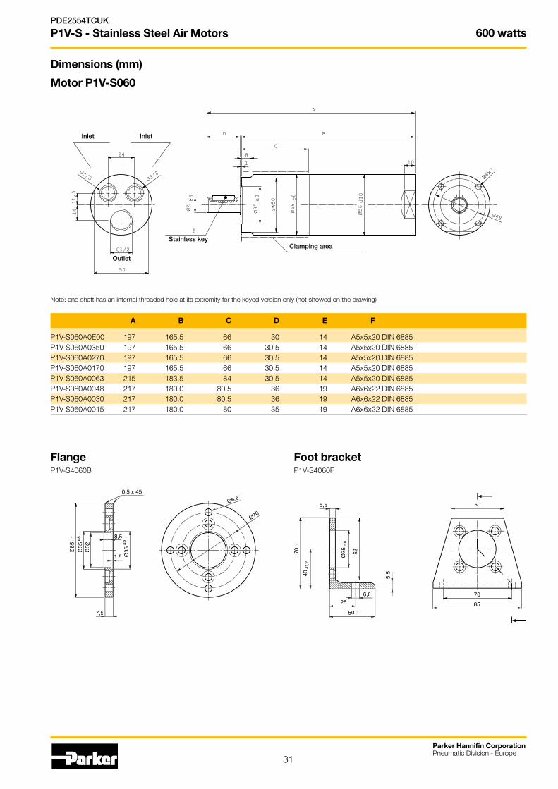
Dimensions (mm)
A B C D E F
P1V-S060A0E00 197 165.5 66 30 14 A5x5x20 DIN 6885P1V-S060A0350 197 165.5 66 30.5 14 A5x5x20 DIN 6885P1V-S060A0270 197 165.5 66 30.5 14 A5x5x20 DIN 6885P1V-S060A0170 197 165.5 66 30.5 14 A5x5x20 DIN 6885P1V-S060A0063 215 183.5 84 30.5 14 A5x5x20 DIN 6885P1V-S060A0048 217 180.0 80.5 36 19 A6x6x22 DIN 6885P1V-S060A0030 217 180.0 80.5 36 19 A6x6x22 DIN 6885P1V-S060A0015 217 180.0 80 35 19 A6x6x22 DIN 6885
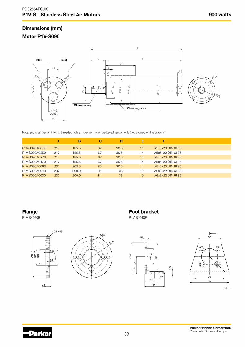
Note: end shaft has an internal threaded hole at its extremity for the keyed version only (not showed on the drawing)
32
Parker Hannifin CorporationPneumatic Division - Europe
PDE2554TCUK
P1V-S - Stainless Steel Air Motors 900 watts
Possible working range of motor.
Optimum working range of motor.
Higher speeds = more vane wearLower speeds with high torque = more gearbox wear
M, torque [Nm] P, power [W]
M, torque [Nm] P, power [W]
n, speed [rpm]
M, torque [Nm] P, power [W]
n, speed [rpm]
M, torque [Nm] P, power [W]
n, speed [rpm]
M, torque [Nm] P, power [W]
n, speed [rpm]
M, torque [Nm] P, power [W]
n, speed [rpm]
M, torque [Nm] P, power [W]
n, speed [rpm]
n, speed [rpm]
P1V-S090A0270
P1V-S090A0170 P1V-S090A0063 P1V-S090A0048
P1V-S090A0030
P1V-S090A0C00 P1V-S090A0350
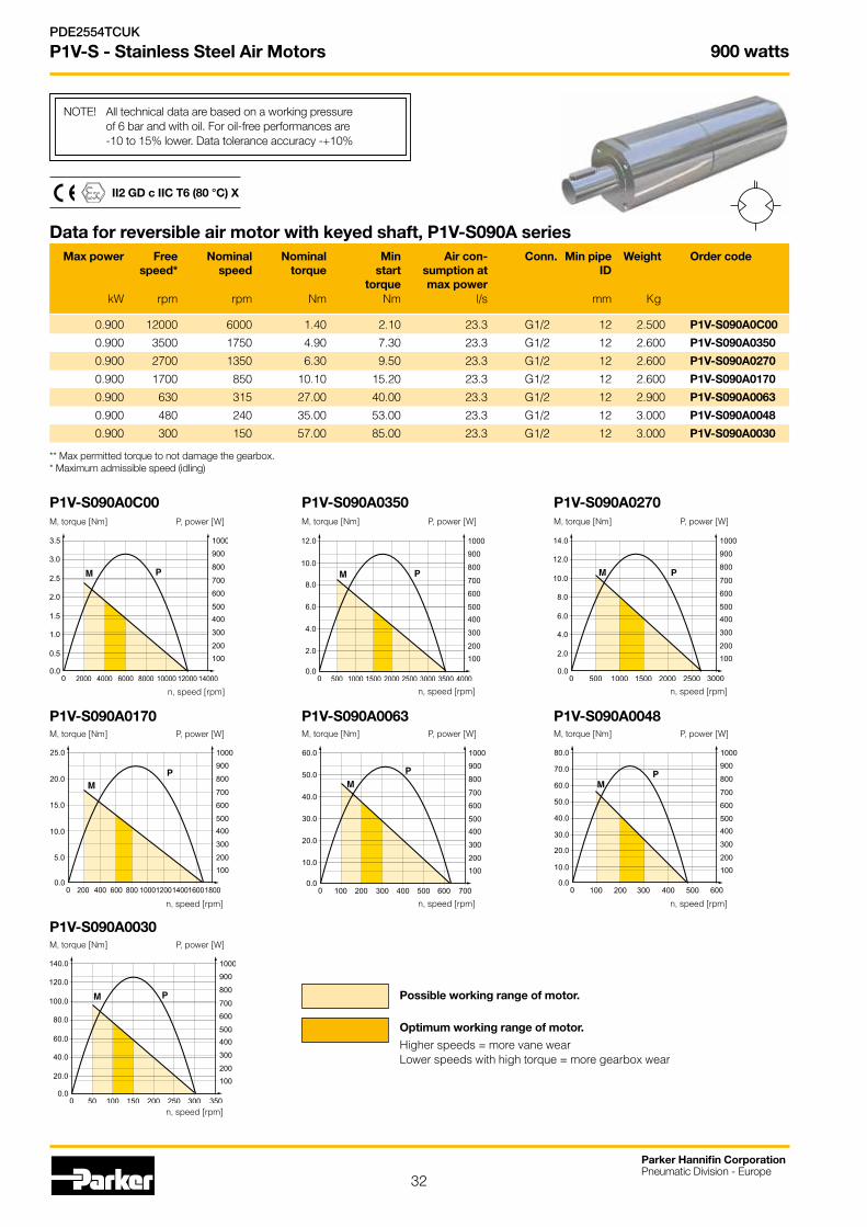
NOTE! All technical data are based on a working pressure of 6 bar and with oil. For oil-free performances are -10 to 15% lower. Data tolerance accuracy -+10%
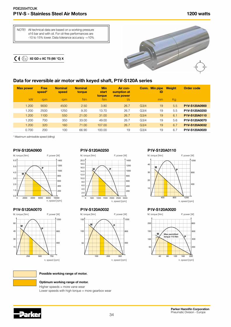
Data for reversible air motor with keyed shaft, P1V-S090A series Max power Free Nominal Nominal Min Air con- Conn. Min pipe Weight Order code speed* speed torque start sumption at ID torque max power kW rpm rpm Nm Nm l/s mm Kg
0.900 12000 6000 1.40 2.10 23.3 G1/2 12 2.500 P1V-S090A0C00
0.900 3500 1750 4.90 7.30 23.3 G1/2 12 2.600 P1V-S090A0350
0.900 2700 1350 6.30 9.50 23.3 G1/2 12 2.600 P1V-S090A0270
0.900 1700 850 10.10 15.20 23.3 G1/2 12 2.600 P1V-S090A0170
0.900 630 315 27.00 40.00 23.3 G1/2 12 2.900 P1V-S090A0063
0.900 480 240 35.00 53.00 23.3 G1/2 12 3.000 P1V-S090A0048
0.900 300 150 57.00 85.00 23.3 G1/2 12 3.000 P1V-S090A0030
** Max permitted torque to not damage the gearbox.* Maximum admissible speed (idling)
II2 GD c IIC T6 (80 °C) X
33
Parker Hannifin CorporationPneumatic Division - Europe
PDE2554TCUK
P1V-S - Stainless Steel Air Motors 900 watts
14
G3/8 G3/8
G1/2
11,5
50
Ø35e8
SW50
Ø56d10
A
B
8
C
F
ØEk6
10
Ø56e8
1
D
Ø48
M6x7
24
Ø70
Ø6,6
8,5
1,5 Ø35
H8
7,5
Ø32
Ø35
Ø85
e8-1
0,5 x 45
Inlet Inlet
Outlet
Stainless keyClamping area
85
70
50
Ø35
H8
5,5
-0,2
40
6,6
5,5
50 -1
25
70 62
-1
Motor P1V-S090
FlangeP1V-S4060B
Foot bracketP1V-S4060F
Dimensions (mm)
A B C D E F
P1V-S090A0C00 217 185.5 67 30.5 14 A5x5x20 DIN 6885P1V-S090A0350 217 185.5 67 30.5 14 A5x5x20 DIN 6885P1V-S090A0270 217 185.5 67 30.5 14 A5x5x20 DIN 6885P1V-S090A0170 217 185.5 67 30.5 14 A5x5x20 DIN 6885P1V-S090A0063 235 203.5 85 30.5 14 A5x5x20 DIN 6885P1V-S090A0048 237 200.0 81 36 19 A6x6x22 DIN 6885P1V-S090A0030 237 200.0 81 36 19 A6x6x22 DIN 6885
Note: end shaft has an internal threaded hole at its extremity for the keyed version only (not showed on the drawing)
34
Parker Hannifin CorporationPneumatic Division - Europe
PDE2554TCUK
P1V-S - Stainless Steel Air Motors 1200 watts
1200
400
800
10
20
30
40M
P
400 800 1200
1200
400
800
15
30
45
60M
P
250 500 750
1200
400
800
50
100
150
M P
100 200 300
800
200
400
600
100
150
50
200
MP
40 80 160 200120
Max permitted torque 110 Nm
Possible working range of motor.
Optimum working range of motor.
Higher speeds = more vane wearLower speeds with high torque = more gearbox wear
M, torque [Nm] P, power [W]
M, torque [Nm] P, power [W]
n, speed [rpm]
M, torque [Nm] P, power [W]
n, speed [rpm]
M, torque [Nm] P, power [W]
n, speed [rpm]
M, torque [Nm] P, power [W]
n, speed [rpm]
M, torque [Nm] P, power [W]
n, speed [rpm]
n, speed [rpm]
P1V-S120A0900 P1V-S120A0250 P1V-S120A0110
P1V-S120A0070 P1V-S120A0032 P1V-S120A0020
II2 GD c IIC T5 (95 °C) X
NOTE! All technical data are based on a working pressure of 6 bar and with oil. For oil-free performances are -10 to 15% lower. Data tolerance accuracy -+10%
Data for reversible air motor with keyed shaft, P1V-S120A series
Max power Free Nominal Nominal Min Air con- Conn. Min pipe Weight Order code speed* speed torque start sumption at ID torque max power kW rpm rpm Nm Nm l/s mm Kg
1.200 9000 4500 2.50 3.80 26.7 G3/4 19 5.5 P1V-S120A0900
1.200 2500 1250 9.20 13.70 26.7 G3/4 19 5.5 P1V-S120A0250
1.200 1100 550 21.00 31.00 26.7 G3/4 19 6.1 P1V-S120A0110
1.200 700 350 33.00 49.00 26.7 G3/4 19 5.6 P1V-S120A0070
1.200 320 160 71.00 107.00 26.7 G3/4 19 6.7 P1V-S120A0032
0.700 200 100 66.90 100.00 19 G3/4 19 6.7 P1V-S120A0020
* Maximum admissible speed (idling)
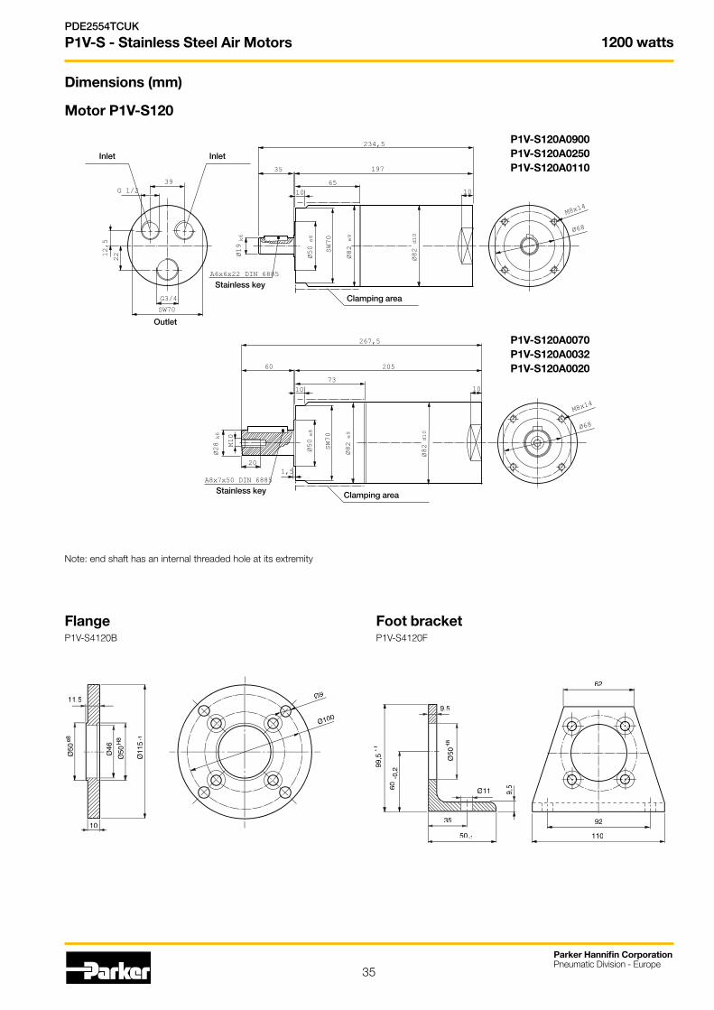
35
Parker Hannifin CorporationPneumatic Division - Europe
PDE2554TCUK
P1V-S - Stainless Steel Air Motors 1200 watts
11,5
Ø50
H8
10
Ø46
Ø50
e8 -1
Ø100
Ø9
Ø11
5
110
92
62
Ø50
H8
9,5
Ø11 9,5
50
35
-1
99,5
1+
-0,2
60
Ø50
e8
SW70
Ø82
d10
234,5
197
1065
A6x6x22 DIN 6885
Ø19k6
10
Ø82
e9
35
22
G3/4
12,5
SW70
G 1/239
Ø68
M8x14
Ø50e8
SW70
Ø82
d10
267,5
205
1073
A8x7x50 DIN 6885
Ø28
k6
10
Ø82
e9
60
Ø68
M8x14
20
M10
1,5
Motor P1V-S120
P1V-S120A0900P1V-S120A0250P1V-S120A0110
P1V-S120A0070P1V-S120A0032P1V-S120A0020
FlangeP1V-S4120B
Inlet Inlet
Outlet
Stainless key
Clamping area
Clamping areaStainless key
Foot bracketP1V-S4120F
Dimensions (mm)
Note: end shaft has an internal threaded hole at its extremity
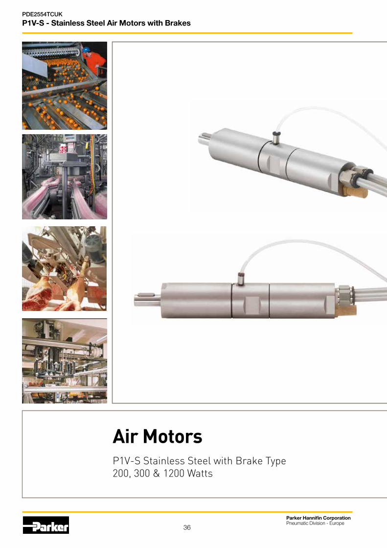
36
Parker Hannifin CorporationPneumatic Division - Europe
PDE2554TCUK
P1V-S - Stainless Steel Air Motors with Brakes
Air MotorsP1V-S Stainless Steel with Brake Type200, 300 & 1200 Watts
37
Parker Hannifin CorporationPneumatic Division - Europe
PDE2554TCUK
P1V-S - Stainless Steel Air Motors with Brakes 200, 300 & 1200 watts
Contents Page
Introduction ................................................................................................. 38Technical data ............................................................................................. 39Material specification ................................................................................... 39
Stainless Steel Air Motors with Brakes 200 watts ......................................... 40Dimensions .................................................................................................. 41
Stainless Steel Air Motors with Brakes 300 watts ......................................... 42Dimensions .................................................................................................. 43
Stainless Steel Air Motors with Brakes 1200 watts ....................................... 44Dimensions .................................................................................................. 45
Mountings ................................................................................................... 56Lubrication and service life ........................................................................... 57Service kits ........................................................................................... 58 - 59
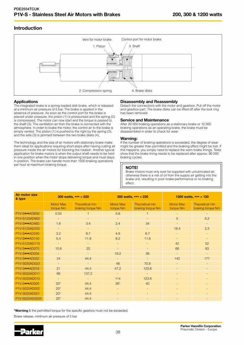
38
Parker Hannifin CorporationPneumatic Division - Europe
PDE2554TCUK
P1V-S - Stainless Steel Air Motors with Brakes
ApplicationsThe integrated brake is a spring-loaded disk brake, which is released at a minimum air pressure of 5 bar. The brake is applied in the absence of pressure. As soon as the control port for the brake is placed under pressure, the piston (1) is pressurised and the spring (2) is compressed. The motor can now start and the torque is passed to the shaft (3). The ventilation air from the brake is connected with the atmosphere. In order to brake the motor, the control air to the brake is simply vented. The piston (1) is pushed to the right by the spring (2), and the axle (3) is jammed between the two brake disks (4).
The technology and the size of air motors with stationary brake make them ideal for applications requiring short stops after having cutting air pressure inside the air motors for blocking the rotation. Another typical application for brake motors is when the output shaft needs to be held in one position when the motor stops delivering torque and must stays in position. The brake can handle more than 1500 braking operations per hour at maximum braking torque.
1. Piston
Vent for motor brake Control port for motor brake
3. Shaft
2. Compression spring 4. Brake disks
NOTE! Brake motors must only ever be supplied with unlubricated air, otherwise there is a risk of oil from the supply air getting into the brake unit, resulting in poor brake performance or no braking effect.
Disassembly and ReassemblyDetach the connections with the motor and gearbox. Pull off the motor and gearbox part. The brake disks can be lifted off after the lock ring has been removed.
Service and MaintenanceAfter 20 000 braking operations as a stationary brake or 10 000 braking operations as an operating brake, the brake must be disassembled in order to check for wear.
Warning:If the number of braking operations is exceeded, the degree of wear might be greater than permitted and the braking effect might be lost. If this happens, you simply need to replace the worn brake linings. Tests show that the brake lining needs to be replaced after approx. 90 000 braking cycles.
200, 300 & 1200 watts
Introduction
Air motor size& type
200 watts, ••• = 020 300 watts, ••• = 030 1200 watts, ••• = 120
Motor Max torque Nm
Theoretical min braking torque Nm
Motor Max torque Nm
Theoretical min braking torque Nm
Motor Max torque Nm
Theoretical min braking torque Nm
P1V-S•••ADE50 0.52 1 0.8 1 - -
P1V-S120AD900 - - - - 5 6.2
P1V-S•••AD460 1.6 3.4 2.4 34 - -
P1V-S120AD250 - - - - 18.4 2.3
P1V-S•••AD240 3.2 6.7 4.8 6.7 - -
P1V-S•••AD140 5.4 11.8 8.2 11.8 - -
P1V-S120AD110 - - - - 42 52
P1V-S•••AD070 10.8 20 - - 66 83
P1V-S•••AD034 - - 19.2 36 - -
P1V-S•••AD032 24 44.4 - - 142 177
P1V-S030AD023 - - 48 70.8 - -
P1V-S•••AD018 21 44.4 47.2 123.6 - -
P1V-S020AD011 66 137.2 - - - -
P1V-S030AD010 - - 114 123.6 - -
P1V-S•••AD005 20* 44.4 36* 40 - -
P1V-S020AD002 20* 44.4 - - - -
P1V-S020AD001 20* 44.4 - - - -
P1V-S020AD0005 20* 44.4 - - - -
*Warning !: the permitted torque for the specific gearbox must not be exceeded.
Brake release: minimum air pressure of 5 bar
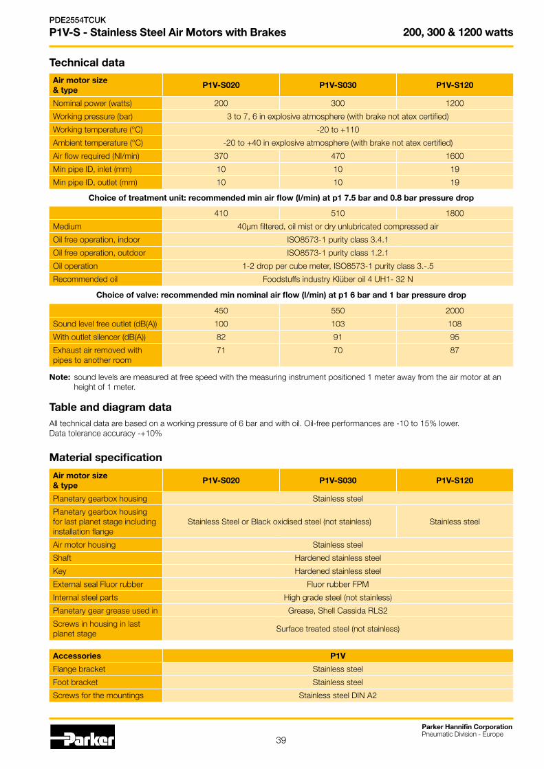
39
Parker Hannifin CorporationPneumatic Division - Europe
PDE2554TCUK
P1V-S - Stainless Steel Air Motors with Brakes 200, 300 & 1200 watts
Table and diagram dataAll technical data are based on a working pressure of 6 bar and with oil. Oil-free performances are -10 to 15% lower. Data tolerance accuracy -+10%
Air motor size& type
P1V-S020 P1V-S030 P1V-S120
Nominal power (watts) 200 300 1200
Working pressure (bar) 3 to 7, 6 in explosive atmosphere (with brake not atex certified)
Working temperature (°C) -20 to +110
Ambient temperature (°C) -20 to +40 in explosive atmosphere (with brake not atex certified)
Air flow required (NI/min) 370 470 1600
Min pipe ID, inlet (mm) 10 10 19
Min pipe ID, outlet (mm) 10 10 19
Choice of treatment unit: recommended min air flow (l/min) at p1 7.5 bar and 0.8 bar pressure drop
410 510 1800
Medium 40µm filtered, oil mist or dry unlubricated compressed air
Oil free operation, indoor ISO8573-1 purity class 3.4.1
Oil free operation, outdoor ISO8573-1 purity class 1.2.1
Oil operation 1-2 drop per cube meter, ISO8573-1 purity class 3.-.5
Recommended oil Foodstuffs industry Klüber oil 4 UH1- 32 N
Choice of valve: recommended min nominal air flow (l/min) at p1 6 bar and 1 bar pressure drop
450 550 2000
Sound level free outlet (dB(A)) 100 103 108
With outlet silencer (dB(A)) 82 91 95
Exhaust air removed with pipes to another room
71 70 87
Technical data
Note: sound levels are measured at free speed with the measuring instrument positioned 1 meter away from the air motor at an height of 1 meter.
Material specification
Air motor size& type
P1V-S020 P1V-S030 P1V-S120
Planetary gearbox housing Stainless steel
Planetary gearbox housing for last planet stage including installation flange
Stainless Steel or Black oxidised steel (not stainless) Stainless steel
Air motor housing Stainless steel
Shaft Hardened stainless steel
Key Hardened stainless steel
External seal Fluor rubber Fluor rubber FPM
Internal steel parts High grade steel (not stainless)
Planetary gear grease used in Grease, Shell Cassida RLS2
Screws in housing in last planet stage
Surface treated steel (not stainless)
Accessories P1V
Flange bracket Stainless steel
Foot bracket Stainless steel
Screws for the mountings Stainless steel DIN A2
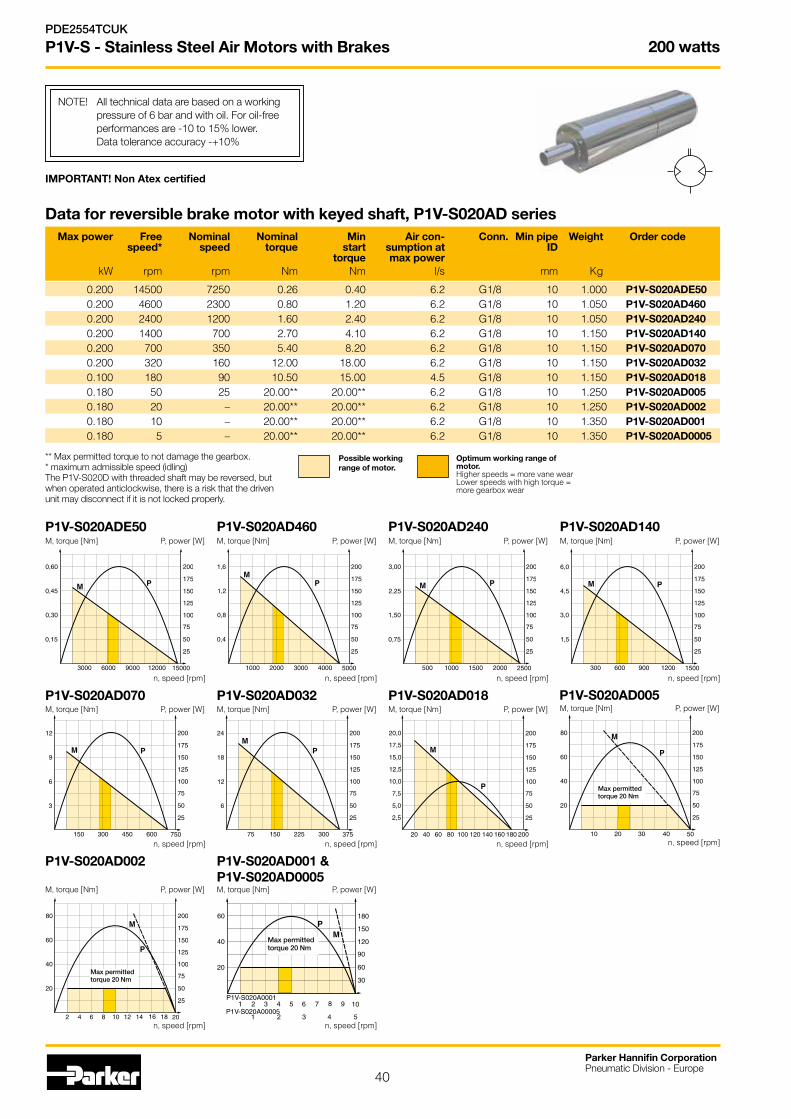
40
Parker Hannifin CorporationPneumatic Division - Europe
PDE2554TCUK
P1V-S - Stainless Steel Air Motors with Brakes
IMPORTANT! Non Atex certified
200 watts
60003000 9000 12000 15000
25
75
125
175
50
100
150
200
0,15
0,30
0,45
0,60
M P
20001000 3000 4000 5000
25
75
125
175
50
100
150
200
0,4
0,8
1,2
1,6M
P
1000500 1500 2000 2500
25
75
125
175
50
100
150
200
0,75
1,50
2,25
3,00
M P
600300 900 1200 1500
25
75
125
175
50
100
150
200
1,5
3,0
4,5
6,0
M P
300150 450 600 750
25
75
125
175
50
100
150
200
3
6
9
12
M P
15075 225 300 375
25
75
125
175
50
100
150
200
6
12
18
24M
P
40 6020 80 100 140 160 200120 180
2,5
5,0
7,5
10,0
12,5
15,0
17,5
20,0
M
P
25
75
125
175
50
100
150
200
2010 30 40 50
25
75
125
175
50
100
150
200
20
40
60
80 M
P
Max permitted torque 20 Nm
2 4 6 8 10 12 14 16 18 20
25
75
125
175
50
100
150
200
20
40
60
80M
P
Max permitted torque 20 Nm
1P1V-S020A0001
P1V-S020A000051
2
2
3
3
4
4
5
5
6 7 8 9 10
30
90
150
60
120
180
20
40
60
MP
Max permitted torque 20 Nm
M, torque [Nm] P, power [W]
n, speed [rpm]
M, torque [Nm] P, power [W]
n, speed [rpm]
M, torque [Nm] P, power [W]
n, speed [rpm]
M, torque [Nm] P, power [W]
n, speed [rpm]
M, torque [Nm] P, power [W]
n, speed [rpm]
M, torque [Nm] P, power [W]
n, speed [rpm]
M, torque [Nm] P, power [W]
n, speed [rpm]
M, torque [Nm] P, power [W]
n, speed [rpm]
M, torque [Nm] P, power [W]
n, speed [rpm]
M, torque [Nm] P, power [W]
n, speed [rpm]
P1V-S020ADE50 P1V-S020AD460 P1V-S020AD240 P1V-S020AD140
P1V-S020AD070 P1V-S020AD018 P1V-S020AD005
P1V-S020AD002 P1V-S020AD001 &P1V-S020AD0005
P1V-S020AD032
Data for reversible brake motor with keyed shaft, P1V-S020AD series Max power Free Nominal Nominal Min Air con- Conn. Min pipe Weight Order code speed* speed torque start sumption at ID torque max power kW rpm rpm Nm Nm l/s mm Kg
0.200 14500 7250 0.26 0.40 6.2 G1/8 10 1.000 P1V-S020ADE50 0.200 4600 2300 0.80 1.20 6.2 G1/8 10 1.050 P1V-S020AD460 0.200 2400 1200 1.60 2.40 6.2 G1/8 10 1.050 P1V-S020AD240 0.200 1400 700 2.70 4.10 6.2 G1/8 10 1.150 P1V-S020AD140 0.200 700 350 5.40 8.20 6.2 G1/8 10 1.150 P1V-S020AD070 0.200 320 160 12.00 18.00 6.2 G1/8 10 1.150 P1V-S020AD032 0.100 180 90 10.50 15.00 4.5 G1/8 10 1.150 P1V-S020AD018 0.180 50 25 20.00** 20.00** 6.2 G1/8 10 1.250 P1V-S020AD005 0.180 20 – 20.00** 20.00** 6.2 G1/8 10 1.250 P1V-S020AD002 0.180 10 – 20.00** 20.00** 6.2 G1/8 10 1.350 P1V-S020AD001 0.180 5 – 20.00** 20.00** 6.2 G1/8 10 1.350 P1V-S020AD0005
NOTE! All technical data are based on a working pressure of 6 bar and with oil. For oil-free performances are -10 to 15% lower. Data tolerance accuracy -+10%
Possible working range of motor.
Optimum working range of motor.Higher speeds = more vane wearLower speeds with high torque = more gearbox wear
** Max permitted torque to not damage the gearbox.* maximum admissible speed (idling)The P1V-S020D with threaded shaft may be reversed, but when operated anticlockwise, there is a risk that the driven unit may disconnect if it is not locked properly.
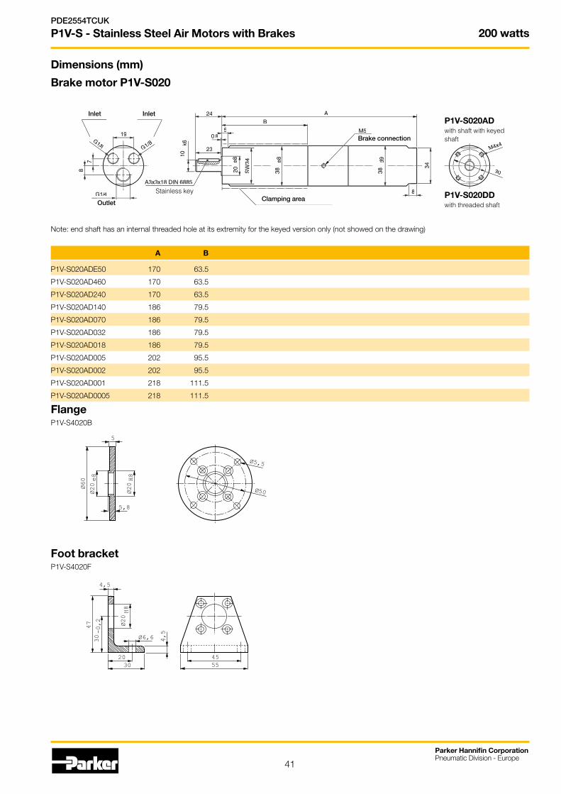
41
Parker Hannifin CorporationPneumatic Division - Europe
PDE2554TCUK
P1V-S - Stainless Steel Air Motors with Brakes 200 watts
19
7
8
G1/81/1/G1/8
G1/4//
M4x4
3020e8
SW
34
38e8
38d9
34
8
24 A
0,85
B
A3x3x18 DIN 6885
23
10k6
M5
Clamping area
InletInlet
Outlet
Stainless key
P1V-S020ADwith shaft with keyed shaft
P1V-S020DDwith threaded shaft
Brake connection
5,8
5
Ø20e8
Ø20H8
Ø5,5
Ø50
Ø60
Ø20H8
4,5
-0,2
30 Ø6,6 4,5
3020
5545
47
FlangeP1V-S4020B
Foot bracketP1V-S4020F
Brake motor P1V-S020
Dimensions (mm)
A B
P1V-S020ADE50 170 63.5
P1V-S020AD460 170 63.5
P1V-S020AD240 170 63.5
P1V-S020AD140 186 79.5
P1V-S020AD070 186 79.5
P1V-S020AD032 186 79.5
P1V-S020AD018 186 79.5
P1V-S020AD005 202 95.5
P1V-S020AD002 202 95.5
P1V-S020AD001 218 111.5
P1V-S020AD0005 218 111.5
Note: end shaft has an internal threaded hole at its extremity for the keyed version only (not showed on the drawing)
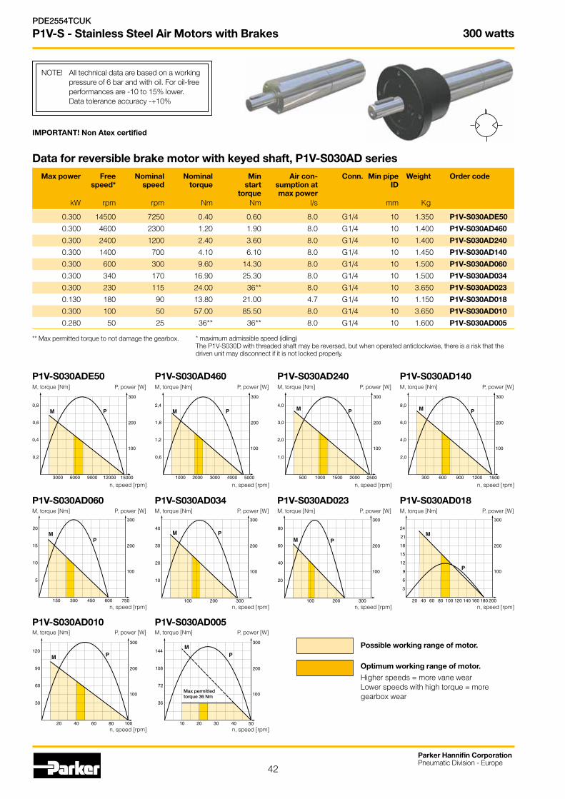
42
Parker Hannifin CorporationPneumatic Division - Europe
PDE2554TCUK
P1V-S - Stainless Steel Air Motors with Brakes 300 watts
IMPORTANT! Non Atex certified
M, torque [Nm] P, power [W]
n, speed [rpm]
M, torque [Nm] P, power [W]
n, speed [rpm]
M, torque [Nm] P, power [W]
n, speed [rpm]
M, torque [Nm] P, power [W]
n, speed [rpm]
M, torque [Nm] P, power [W]
n, speed [rpm]
M, torque [Nm] P, power [W]
n, speed [rpm]
M, torque [Nm] P, power [W]
n, speed [rpm]
M, torque [Nm] P, power [W]
n, speed [rpm]
M, torque [Nm] P, power [W]
n, speed [rpm]
M, torque [Nm] P, power [W]
n, speed [rpm]
60003000 9000 12000 15000
300
100
200
0,2
0,4
0,6
0,8M P
300
100
200
0,6
1,2
1,8
2,4M P
20001000 3000 4000 5000
300
100
200
1,0
2,0
3,0
4,0M P
1000500 1500 2000 2500
300
100
200
2,0
4,0
6,0
8,0M P
600300 900 1200 1500
300
100
200
5
10
15
20M
P
300150 450 600 750
300
100
200
10
20
30
40M P
100 300200 40 6020 80 100 140 160 200120 180
3
6
9
12
15
18
21
24M
P
300
100
200
300
100
200
36
72
108
144M
P
2010 30 40 50
Max permitted torque 36 Nm
300
100
200
20
40
60
80
M P
100 300200
300
100
200
30
60
90
120M P
20 10040 60 80
Possible working range of motor.
Optimum working range of motor.
Higher speeds = more vane wearLower speeds with high torque = more gearbox wear
P1V-S030ADE50 P1V-S030AD460 P1V-S030AD240 P1V-S030AD140
P1V-S030AD060 P1V-S030AD034 P1V-S030AD018
P1V-S030AD010 P1V-S030AD005
P1V-S030AD023
Data for reversible brake motor with keyed shaft, P1V-S030AD series Max power Free Nominal Nominal Min Air con- Conn. Min pipe Weight Order code speed* speed torque start sumption at ID torque max power kW rpm rpm Nm Nm l/s mm Kg
0.300 14500 7250 0.40 0.60 8.0 G1/4 10 1.350 P1V-S030ADE50
0.300 4600 2300 1.20 1.90 8.0 G1/4 10 1.400 P1V-S030AD460
0.300 2400 1200 2.40 3.60 8.0 G1/4 10 1.400 P1V-S030AD240
0.300 1400 700 4.10 6.10 8.0 G1/4 10 1.450 P1V-S030AD140
0.300 600 300 9.60 14.30 8.0 G1/4 10 1.500 P1V-S030AD060
0.300 340 170 16.90 25.30 8.0 G1/4 10 1.500 P1V-S030AD034
0.300 230 115 24.00 36** 8.0 G1/4 10 3.650 P1V-S030AD023
0.130 180 90 13.80 21.00 4.7 G1/4 10 1.150 P1V-S030AD018
0.300 100 50 57.00 85.50 8.0 G1/4 10 3.650 P1V-S030AD010
0.280 50 25 36** 36** 8.0 G1/4 10 1.600 P1V-S030AD005
NOTE! All technical data are based on a working pressure of 6 bar and with oil. For oil-free performances are -10 to 15% lower. Data tolerance accuracy -+10%
** Max permitted torque to not damage the gearbox. * maximum admissible speed (idling)The P1V-S030D with threaded shaft may be reversed, but when operated anticlockwise, there is a risk that the driven unit may disconnect if it is not locked properly.
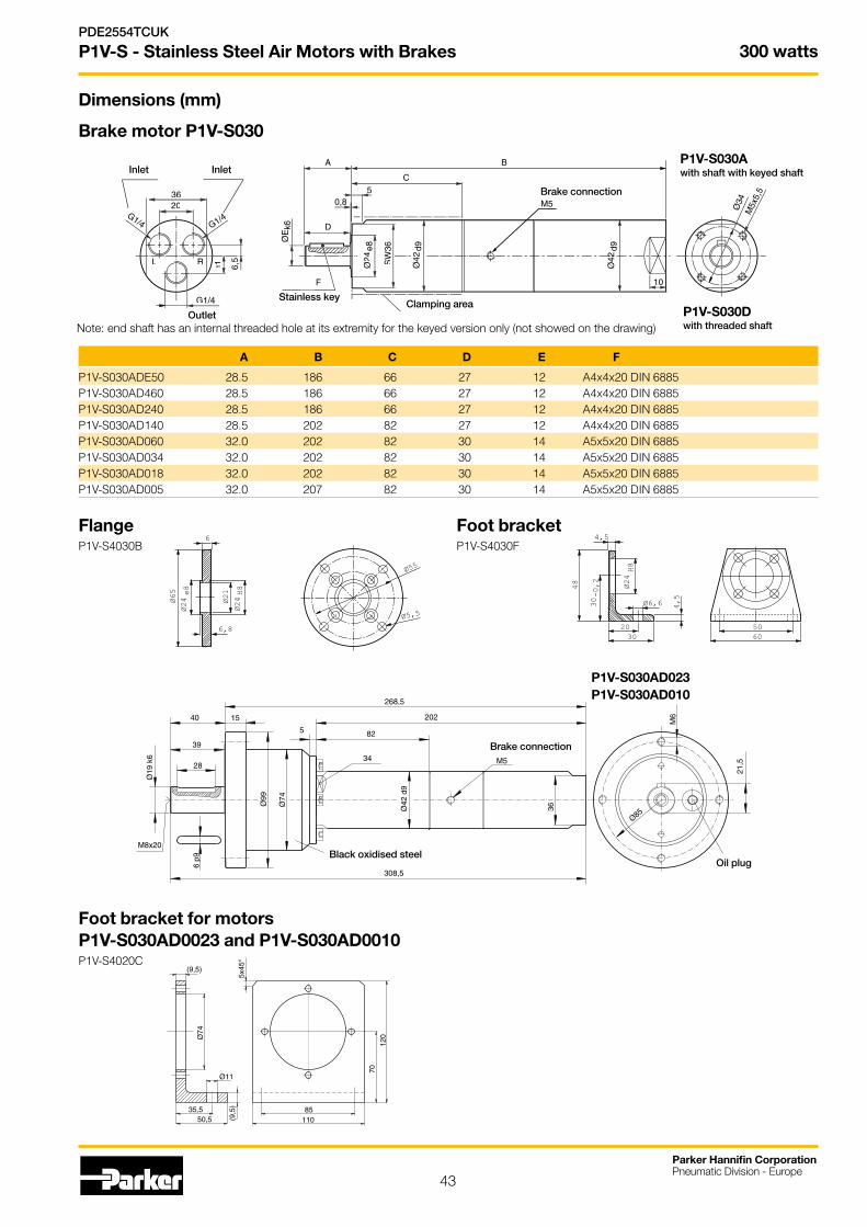
43
Parker Hannifin CorporationPneumatic Division - Europe
PDE2554TCUK
P1V-S - Stainless Steel Air Motors with Brakes
268,5
202
82
Ø42
d9
M6
21,5
Ø85
M8x20
40
39
28
308,5
6 p9
36
Ø19
k6 34
15
5
Ø99
Ø74
M5
300 watts
20
6,5
11G1/4 G1/4
G1/4
36
L R Ø24
e8
SW
36
Ø42
d9
A B
0,85
C
F
D
ØE
k610
Ø42
d9
M5x
5,5
Ø34M5
Inlet Inlet
Outlet
Stainless keyClamping area
P1V-S030Awith shaft with keyed shaft
P1V-S030Dwith threaded shaft
Foot bracket for motors P1V-S030AD0023 and P1V-S030AD0010P1V-S4020C
Black oxidised steelOil plug
P1V-S030AD023P1V-S030AD010
Brake connection
Brake connection
Ø5,5
Ø55
6,8
6
Ø24e8
Ø24H8
Ø21
Ø65
6050
Ø24H8
4,5
-0,2
30 Ø6,6 4,5
3020
48
8535,550,5
Ø11
(9,5)
(9,5
)
Ø74
110
70
120
5x45
°
Brake motor P1V-S030
A B C D E F
P1V-S030ADE50 28.5 186 66 27 12 A4x4x20 DIN 6885P1V-S030AD460 28.5 186 66 27 12 A4x4x20 DIN 6885P1V-S030AD240 28.5 186 66 27 12 A4x4x20 DIN 6885P1V-S030AD140 28.5 202 82 27 12 A4x4x20 DIN 6885P1V-S030AD060 32.0 202 82 30 14 A5x5x20 DIN 6885P1V-S030AD034 32.0 202 82 30 14 A5x5x20 DIN 6885P1V-S030AD018 32.0 202 82 30 14 A5x5x20 DIN 6885P1V-S030AD005 32.0 207 82 30 14 A5x5x20 DIN 6885
FlangeP1V-S4030B
Foot bracketP1V-S4030F
Dimensions (mm)
Note: end shaft has an internal threaded hole at its extremity for the keyed version only (not showed on the drawing)
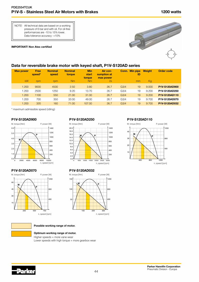
44
Parker Hannifin CorporationPneumatic Division - Europe
PDE2554TCUK
P1V-S - Stainless Steel Air Motors with Brakes 1200 watts
IMPORTANT! Non Atex certified
1200
400
800
10
20
30
40M
P
400 800 1200
1200
400
800
15
30
45
60M
P
250 500 750
1200
400
800
50
100
150
M P
100 200 300
Possible working range of motor.
Optimum working range of motor.
Higher speeds = more vane wearLower speeds with high torque = more gearbox wear
M, torque [Nm] P, power [W]
M, torque [Nm] P, power [W]
n, speed [rpm]
M, torque [Nm] P, power [W]
n, speed [rpm]
M, torque [Nm] P, power [W]
n, speed [rpm]
M, torque [Nm] P, power [W]
n, speed [rpm]n, speed [rpm]
P1V-S120AD900 P1V-S120AD250 P1V-S120AD110
P1V-S120AD070 P1V-S120AD032
Data for reversible brake motor with keyed shaft, P1V-S120AD series Max power Free Nominal Nominal Min Air con- Conn. Min pipe Weight Order code speed* speed torque start sumption at ID torque max power kW rpm rpm Nm Nm l/s mm Kg
1.200 9000 4500 2.50 3.80 26.7 G3/4 19 9.000 P1V-S120AD900
1.200 2500 1250 9.20 13.70 26.7 G3/4 19 9.200 P1V-S120AD250
1.200 1100 550 21.00 31.00 26.7 G3/4 19 9.200 P1V-S120AD110
1.200 700 350 33.00 49.00 26.7 G3/4 19 9.700 P1V-S120AD070
1.200 320 160 71.00 107.00 26.7 G3/4 19 9.700 P1V-S120AD032
* maximum admissible speed (idling)
NOTE! All technical data are based on a working pressure of 6 bar and with oil. For oil-free performances are -10 to 15% lower. Data tolerance accuracy -+10%
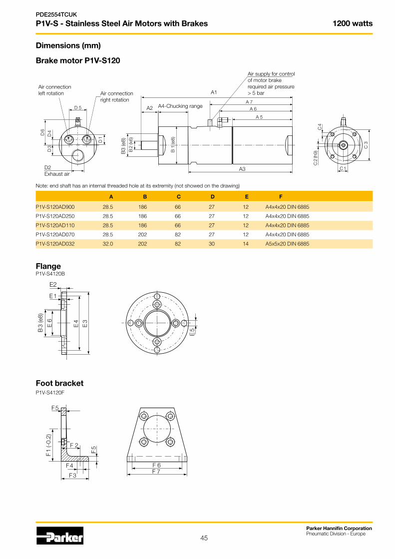
45
Parker Hannifin CorporationPneumatic Division - Europe
PDE2554TCUK
P1V-S - Stainless Steel Air Motors with Brakes
B 3
(e8)
E 6
E 1
E 5
D 3
D 5
D 4D 6
D 1
C 3
C 1
C 4
C 2
(h9)B
2 (k
6)
B 1
(e8)
A 7
A 6
A 5
E 2
E 4
E 3
A3D2Exhaust air
Air connectionleft rotation Air connection
right rotation
A2
B3
(e8)
A4-Chucking range
A1
Air supply for controlof motor brakerequired air pressure> 5 bar
B 3
(e8)
E 6
E 1
E 5
D 3
D 5
D 4D 6
D 1
C 3
C 1
C 4
C 2
(h9)B
2 (k
6)
B 1
(e8)
A 7
A 6
A 5
E 2
E 4
E 3
B 3
(e8)
E 6
E 1
E 5
D 3
D 5
D 4D 6
D 1
C 3
C 1
C 4
C 2
(h9)B
2 (k
6)
B 1
(e8)
A 7
A 6
A 5
E 2
E 4
E 3
E2
1200 watts
Dimensions (mm)
FlangeP1V-S4120B
Foot bracketP1V-S4120F
Brake motor P1V-S120
A B C D E F
P1V-S120AD900 28.5 186 66 27 12 A4x4x20 DIN 6885
P1V-S120AD250 28.5 186 66 27 12 A4x4x20 DIN 6885
P1V-S120AD110 28.5 186 66 27 12 A4x4x20 DIN 6885
P1V-S120AD070 28.5 202 82 27 12 A4x4x20 DIN 6885
P1V-S120AD032 32.0 202 82 30 14 A5x5x20 DIN 6885
Note: end shaft has an internal threaded hole at its extremity (not showed on the drawing)
46
Parker Hannifin CorporationPneumatic Division - Europe
PDE2554TCUK
P1V-S - Stainless Steel Air Motors with Brakes
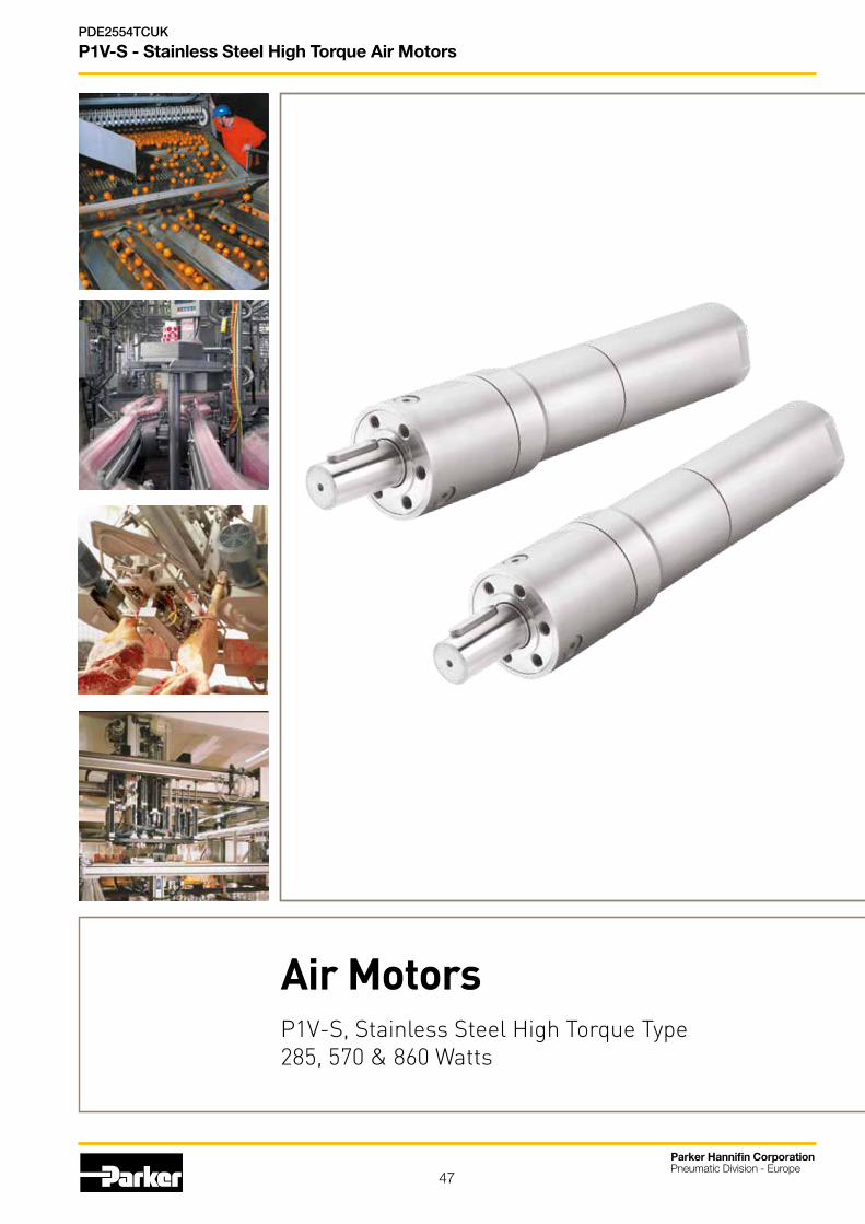
47
Parker Hannifin CorporationPneumatic Division - Europe
PDE2554TCUK
P1V-S - Stainless Steel High Torque Air Motors
Air MotorsP1V-S, Stainless Steel High Torque Type285, 570 & 860 Watts
48
Parker Hannifin CorporationPneumatic Division - Europe
PDE2554TCUK
P1V-S - Stainless Steel High Torque Air Motors
Contents Page
Technical data ............................................................................................. 49Material specification ................................................................................... 49Stainless Steel High Torque Air Motors P1V-S 285 W .................................. 50Dimensions .................................................................................................. 51
Stainless Steel High Torque Air Motors P1V-S 570 W .................................. 52Dimensions .................................................................................................. 53
Stainless Steel High Torque Air Motors P1V-S 860 W .................................. 54Dimensions .................................................................................................. 55
Mountings ................................................................................................... 56Lubrication and service life ........................................................................... 57Service kits ........................................................................................... 58 - 59Introduction to the ATEX directive ........................................................ 60 - 64
285, 570 & 860 watts

49
Parker Hannifin CorporationPneumatic Division - Europe
PDE2554TCUK
P1V-S - Stainless Steel High Torque Air Motors 285, 570 & 860 watts
Table and diagram dataAll technical data are based on a working pressure of 6 bar and with oil. Oil-free performances are -10 to 15% lower. Data tolerance accuracy -+10%
Air motor size& type
P1V-S028 P1V-S057 P1V-S086
Nominal power (watts) 285 570 860
Working pressure (bar) 3 to 7, 6 in explosive atmosphere (high torque not atex certified)
Working temperature (°C) -20 to +110
Ambient temperature (°C) -20 to +40 in explosive atmosphere (high torque not atex certified)
Air flow required (NI/min) 470 850 1400
Min pipe ID, inlet (mm) 10 12 12
Min pipe ID, outlet (mm) 10 12 12
Choice of treatment unit: recommended min air flow (l/min) at p1 7.5 bar and 0.8 bar pressure drop
510 900 1500
Medium 40µm filtered, oil mist or dry unlubricated compressed air
Oil free operation, indoor ISO8573-1 purity class 3.4.1
Oil free operation, outdoor ISO8573-1 purity class 1.2.1
Oil operation 1-2 drop per cube meter, ISO8573-1 purity class 3.-.5
Recommended oil Foodstuffs industry Klüber oil 4 UH1- 32 N
Choice of valve: recommended min nominal air flow (l/min) at p1 6 bar and 1 bar pressure drop
550 950 1600
Sound level free outlet (dB(A)) 103 103 106
With outlet silencer (dB(A)) 91 94 88
Exhaust air removed with pipes to another room
70 76 80
Technical data
Note: sound levels are measured at free speed with the measuring instrument positioned 1 meter away from the air motor at an height of 1 meter.
Material specification
Air motor size& type
P1V-S028 P1V-S057 P1V-S086
Planetary gearbox housing Stainless steel
Air motor housing Stainless steel
Shaft Hardened stainless steel
Key Hardened stainless steel
External seal Fluor rubber Fluor rubber FPM
Internal steel parts High grade steel (not stainless)
Planetary gear grease used in Grease, Shell Cassida RLS2
Screws in housing in last planet stage
Surface treated steel (not stainless)
Accessories P1V
Flange bracket Stainless steel
Foot bracket Stainless steel
Screws for the mountings Stainless steel DIN A2
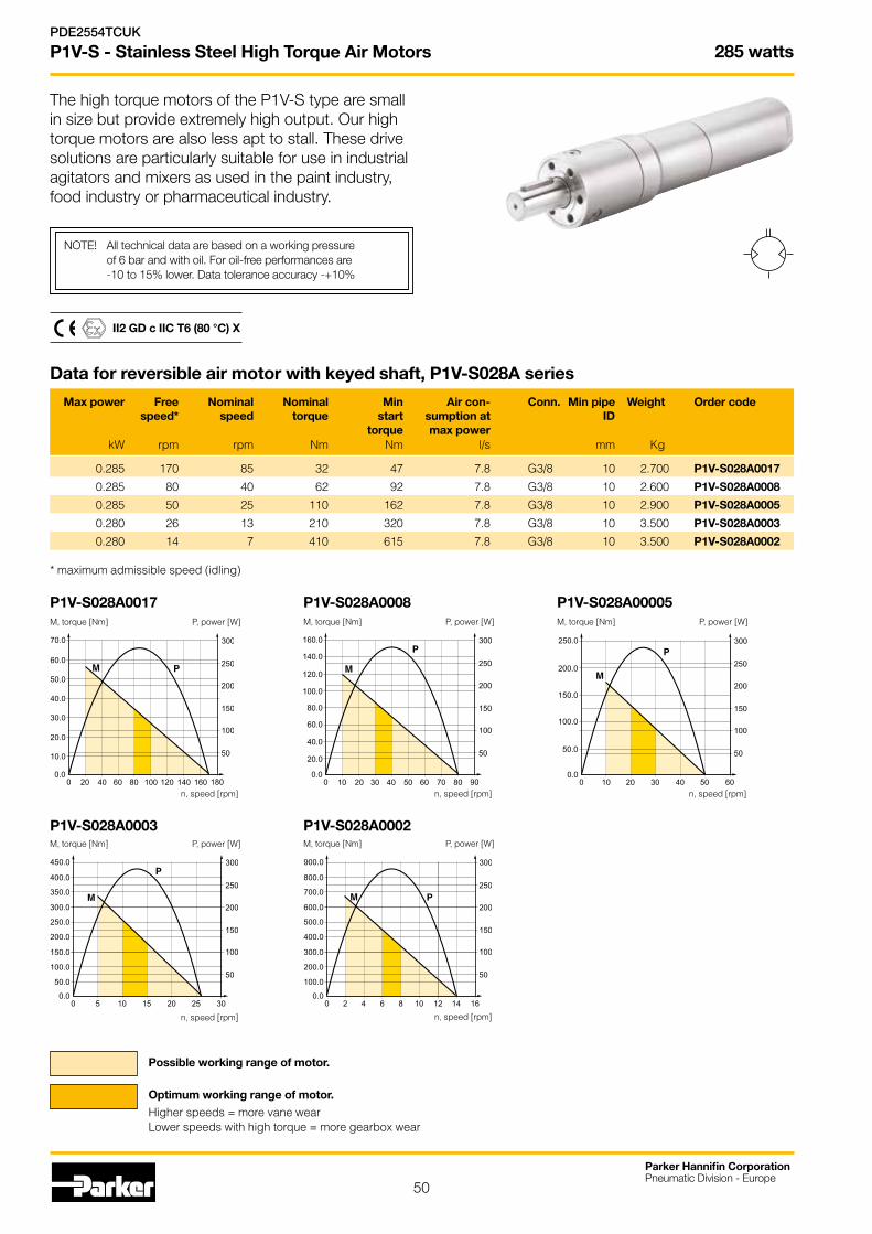
50
Parker Hannifin CorporationPneumatic Division - Europe
PDE2554TCUK
P1V-S - Stainless Steel High Torque Air Motors
NOTE! All technical data are based on a working pressure of 6 bar and with oil. For oil-free performances are -10 to 15% lower. Data tolerance accuracy -+10%
Possible working range of motor.
Optimum working range of motor.
Higher speeds = more vane wearLower speeds with high torque = more gearbox wear
M, torque [Nm] P, power [W]
M, torque [Nm] P, power [W]
M, torque [Nm] P, power [W]
M, torque [Nm] P, power [W]
n, speed [rpm]
M, torque [Nm] P, power [W]
P1V-S028A0017 P1V-S028A0008 P1V-S028A00005
P1V-S028A0003 P1V-S028A0002
285 watts
n, speed [rpm]
n, speed [rpm] n, speed [rpm]n, speed [rpm]
* maximum admissible speed (idling)
The high torque motors of the P1V-S type are small in size but provide extremely high output. Our high torque motors are also less apt to stall. These drive solutions are particularly suitable for use in industrial agitators and mixers as used in the paint industry, food industry or pharmaceutical industry.
Data for reversible air motor with keyed shaft, P1V-S028A series
Max power Free Nominal Nominal Min Air con- Conn. Min pipe Weight Order code speed* speed torque start sumption at ID torque max power kW rpm rpm Nm Nm l/s mm Kg
0.285 170 85 32 47 7.8 G3/8 10 2.700 P1V-S028A0017
0.285 80 40 62 92 7.8 G3/8 10 2.600 P1V-S028A0008
0.285 50 25 110 162 7.8 G3/8 10 2.900 P1V-S028A0005
0.280 26 13 210 320 7.8 G3/8 10 3.500 P1V-S028A0003
0.280 14 7 410 615 7.8 G3/8 10 3.500 P1V-S028A0002
II2 GD c IIC T6 (80 °C) X
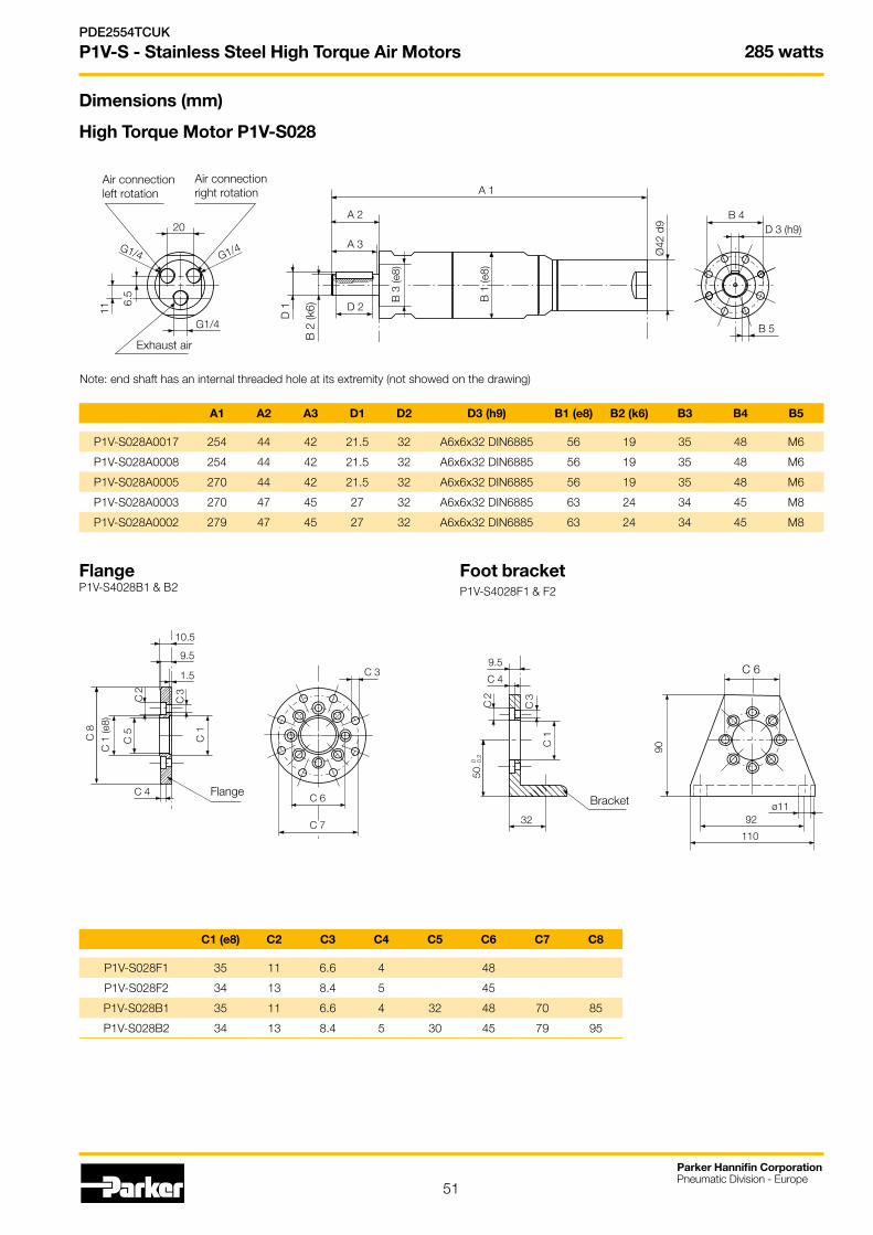
51
Parker Hannifin CorporationPneumatic Division - Europe
PDE2554TCUK
P1V-S - Stainless Steel High Torque Air Motors 285 watts
C 6
FlangeBracket
Exhaust air
Air connectionleft rotation
Air connectionright rotation
High Torque Motor P1V-S028
FlangeP1V-S4028B1 & B2
Foot bracketP1V-S4028F1 & F2
Dimensions (mm)
A1 A2 A3 D1 D2 D3 (h9) B1 (e8) B2 (k6) B3 B4 B5
P1V-S028A0017 254 44 42 21.5 32 A6x6x32 DIN6885 56 19 35 48 M6
P1V-S028A0008 254 44 42 21.5 32 A6x6x32 DIN6885 56 19 35 48 M6
P1V-S028A0005 270 44 42 21.5 32 A6x6x32 DIN6885 56 19 35 48 M6
P1V-S028A0003 270 47 45 27 32 A6x6x32 DIN6885 63 24 34 45 M8
P1V-S028A0002 279 47 45 27 32 A6x6x32 DIN6885 63 24 34 45 M8
C1 (e8) C2 C3 C4 C5 C6 C7 C8
P1V-S028F1 35 11 6.6 4 48
P1V-S028F2 34 13 8.4 5 45
P1V-S028B1 35 11 6.6 4 32 48 70 85
P1V-S028B2 34 13 8.4 5 30 45 79 95
Note: end shaft has an internal threaded hole at its extremity (not showed on the drawing)
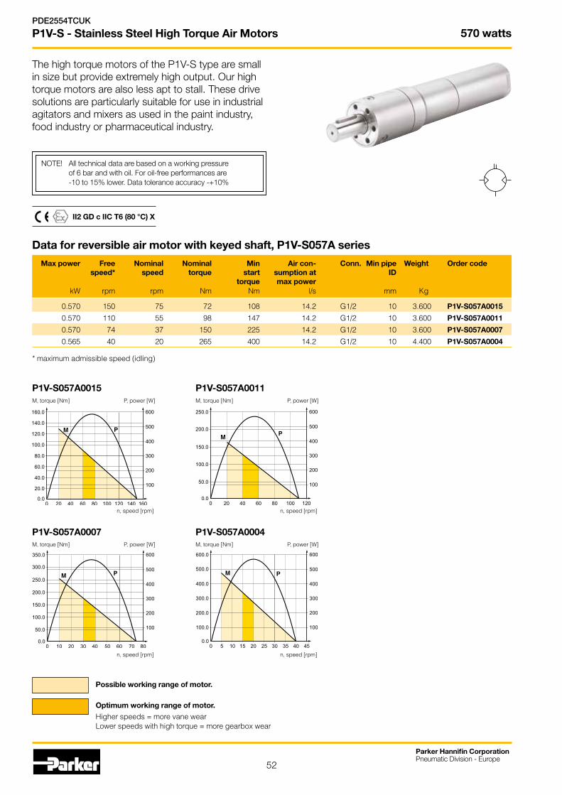
52
Parker Hannifin CorporationPneumatic Division - Europe
PDE2554TCUK
P1V-S - Stainless Steel High Torque Air Motors 570 watts
NOTE! All technical data are based on a working pressure of 6 bar and with oil. For oil-free performances are -10 to 15% lower. Data tolerance accuracy -+10%
Possible working range of motor.
Optimum working range of motor.
Higher speeds = more vane wearLower speeds with high torque = more gearbox wear
M, torque [Nm] P, power [W]
n, speed [rpm]
P1V-S057A0015 P1V-S057A0011
P1V-S057A0007 P1V-S057A0004
M, torque [Nm] P, power [W]
n, speed [rpm]
M, torque [Nm] P, power [W]
n, speed [rpm]
M, torque [Nm] P, power [W]
n, speed [rpm]
The high torque motors of the P1V-S type are small in size but provide extremely high output. Our high torque motors are also less apt to stall. These drive solutions are particularly suitable for use in industrial agitators and mixers as used in the paint industry, food industry or pharmaceutical industry.
* maximum admissible speed (idling)
Data for reversible air motor with keyed shaft, P1V-S057A series
Max power Free Nominal Nominal Min Air con- Conn. Min pipe Weight Order code speed* speed torque start sumption at ID torque max power kW rpm rpm Nm Nm l/s mm Kg
0.570 150 75 72 108 14.2 G1/2 10 3.600 P1V-S057A0015
0.570 110 55 98 147 14.2 G1/2 10 3.600 P1V-S057A0011
0.570 74 37 150 225 14.2 G1/2 10 3.600 P1V-S057A0007
0.565 40 20 265 400 14.2 G1/2 10 4.400 P1V-S057A0004
II2 GD c IIC T6 (80 °C) X

53
Parker Hannifin CorporationPneumatic Division - Europe
PDE2554TCUK
P1V-S - Stainless Steel High Torque Air Motors
Bracket
570 watts
Flange
Exhaust air
Air connectionleft rotation
Air connectionright rotation
High Torque Motor P1V-S057
FlangeP1V-S4028B1 & B2
Foot bracketP1V-S4028F1 & F2
Dimensions (mm)
A1 A2 A3 A4 D1 D3 (h9) D2 B1 (e8) B2 (k6) B3 (e8) B4 B5
P1V-S057A0015 283.5 44 42 98.5 21.5 A6x6x32 DIN6885 32 56 19 35 48 M6
P1V-S057A0011 283.5 44 42 98.5 21.5 A6x6x32 DIN6885 32 56 19 35 48 M6
P1V-S057A0007 283.5 44 42 98.5 21.5 A6x6x32 DIN6885 32 56 19 35 48 M6
P1V-S057A0004 347 47 45 98.5 27 A6x6x32 DIN6885 32 63 24 34 45 M8
C1 (e8) C2 C3 C4 C5 C6 C7 C8
P1V-S028F1 35 11 6.6 4 48
P1V-S028F2 34 13 8.4 5 45
P1V-S028B1 35 11 6.6 4 32 48 70 85
P1V-S028B2 34 13 8.4 5 30 45 79 95
Note: end shaft has an internal threaded hole at its extremity (not showed on the drawing)
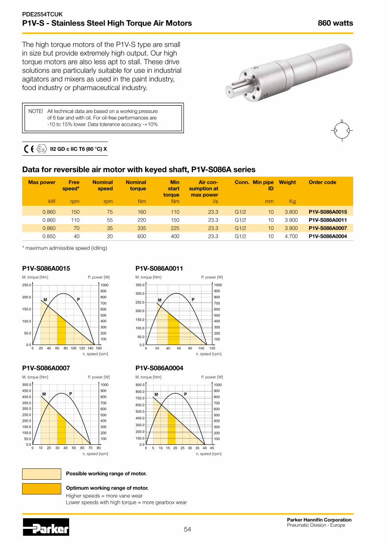
54
Parker Hannifin CorporationPneumatic Division - Europe
PDE2554TCUK
P1V-S - Stainless Steel High Torque Air Motors 860 watts
NOTE! All technical data are based on a working pressure of 6 bar and with oil. For oil-free performances are -10 to 15% lower. Data tolerance accuracy -+10%
Possible working range of motor.
Optimum working range of motor.
Higher speeds = more vane wearLower speeds with high torque = more gearbox wear
M, torque [Nm] P, power [W]
n, speed [rpm]
P1V-S086A0015 P1V-S086A0011
P1V-S086A0007 P1V-S086A0004M, torque [Nm] P, power [W]
n, speed [rpm]
M, torque [Nm] P, power [W]
n, speed [rpm]
M, torque [Nm] P, power [W]
n, speed [rpm]
The high torque motors of the P1V-S type are small in size but provide extremely high output. Our high torque motors are also less apt to stall. These drive solutions are particularly suitable for use in industrial agitators and mixers as used in the paint industry, food industry or pharmaceutical industry.
* maximum admissible speed (idling)
Data for reversible air motor with keyed shaft, P1V-S086A series
Max power Free Nominal Nominal Min Air con- Conn. Min pipe Weight Order code speed* speed torque start sumption at ID torque max power kW rpm rpm Nm Nm l/s mm Kg
0.860 150 75 160 110 23.3 G1/2 10 3.800 P1V-S086A0015
0.860 110 55 220 150 23.3 G1/2 10 3.900 P1V-S086A0011
0.860 70 35 335 225 23.3 G1/2 10 3.900 P1V-S086A0007
0.850 40 20 600 400 23.3 G1/2 10 4.700 P1V-S086A0004
II2 GD c IIC T6 (80 °C) X
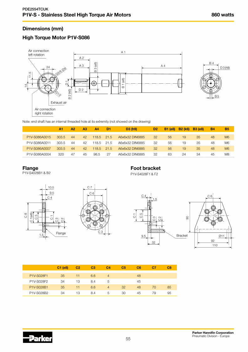
55
Parker Hannifin CorporationPneumatic Division - Europe
PDE2554TCUK
P1V-S - Stainless Steel High Torque Air Motors 860 watts
Bracket
Exhaust air
Air connectionleft rotation
Air connectionright rotation
Flange
High Torque Motor P1V-S086
FlangeP1V-S4028B1 & B2
Foot bracketP1V-S4028F1 & F2
Dimensions (mm)
A1 A2 A3 A4 D1 D3 (h9) D2 B1 (e8) B2 (k6) B3 (e8) B4 B5
P1V-S086A0015 303.5 44 42 118.5 21.5 A6x6x32 DIN6885 32 56 19 35 48 M6
P1V-S086A0011 303.5 44 42 118.5 21.5 A6x6x32 DIN6885 32 56 19 35 48 M6
P1V-S086A0007 303.5 44 42 118.5 21.5 A6x6x32 DIN6885 32 56 19 35 48 M6
P1V-S086A0004 320 47 45 98.5 27 A6x6x32 DIN6885 32 63 24 34 45 M8
C1 (e8) C2 C3 C4 C5 C6 C7 C8
P1V-S028F1 35 11 6.6 4 48
P1V-S028F2 34 13 8.4 5 45
P1V-S028B1 35 11 6.6 4 32 48 70 85
P1V-S028B2 34 13 8.4 5 30 45 79 95
Note: end shaft has an internal threaded hole at its extremity (not showed on the drawing)
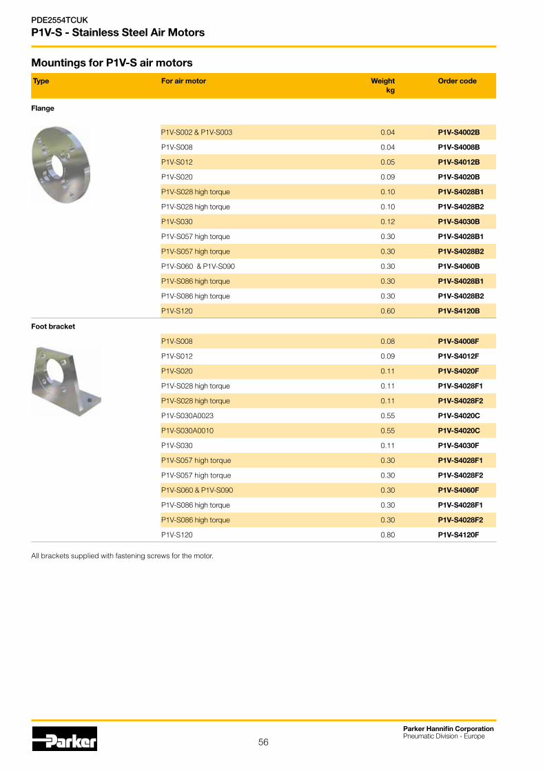
56
Parker Hannifin CorporationPneumatic Division - Europe
PDE2554TCUK
P1V-S - Stainless Steel Air Motors
Mountings for P1V-S air motors
Type For air motor Weight Order code kg
Flange
P1V-S002 & P1V-S003 0.04 P1V-S4002B
P1V-S008 0.04 P1V-S4008B
P1V-S012 0.05 P1V-S4012B
P1V-S020 0.09 P1V-S4020B
P1V-S028 high torque 0.10 P1V-S4028B1
P1V-S028 high torque 0.10 P1V-S4028B2
P1V-S030 0.12 P1V-S4030B
P1V-S057 high torque 0.30 P1V-S4028B1
P1V-S057 high torque 0.30 P1V-S4028B2
P1V-S060 & P1V-S090 0.30 P1V-S4060B
P1V-S086 high torque 0.30 P1V-S4028B1
P1V-S086 high torque 0.30 P1V-S4028B2
P1V-S120 0.60 P1V-S4120B
Foot bracket
P1V-S008 0.08 P1V-S4008F
P1V-S012 0.09 P1V-S4012F
P1V-S020 0.11 P1V-S4020F
P1V-S028 high torque 0.11 P1V-S4028F1
P1V-S028 high torque 0.11 P1V-S4028F2
P1V-S030A0023 0.55 P1V-S4020C
P1V-S030A0010 0.55 P1V-S4020C
P1V-S030 0.11 P1V-S4030F
P1V-S057 high torque 0.30 P1V-S4028F1
P1V-S057 high torque 0.30 P1V-S4028F2
P1V-S060 & P1V-S090 0.30 P1V-S4060F
P1V-S086 high torque 0.30 P1V-S4028F1
P1V-S086 high torque 0.30 P1V-S4028F2
P1V-S120 0.80 P1V-S4120F
All brackets supplied with fastening screws for the motor.
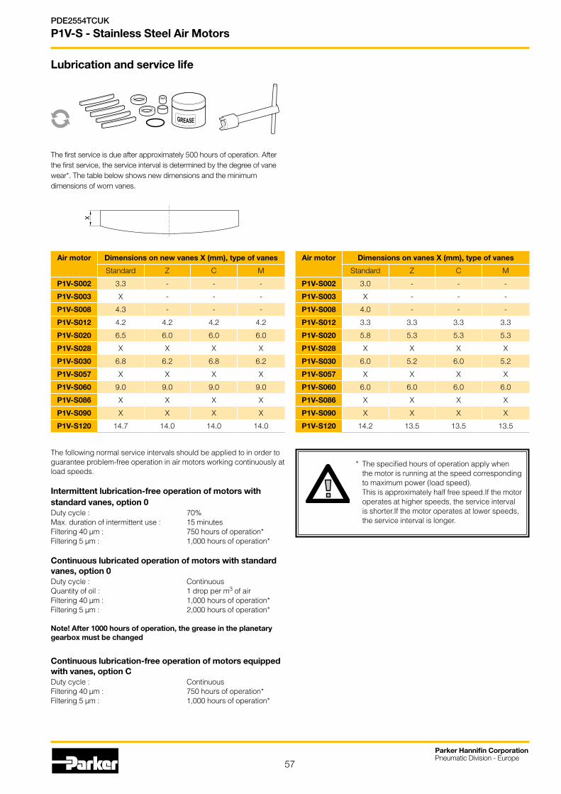
57
Parker Hannifin CorporationPneumatic Division - Europe
PDE2554TCUK
P1V-S - Stainless Steel Air Motors
Lubrication and service life
X
The first service is due after approximately 500 hours of operation. After the first service, the service interval is determined by the degree of vane wear*. The table below shows new dimensions and the minimum dimensions of worn vanes.
The following normal service intervals should be applied to in order to guarantee problem-free operation in air motors working continuously at load speeds.
Intermittent lubrication-free operation of motors with standard vanes, option 0Duty cycle : 70%Max. duration of intermittent use : 15 minutesFiltering 40 µm : 750 hours of operation*Filtering 5 µm : 1,000 hours of operation*
Continuous lubricated operation of motors with standard vanes, option 0 Duty cycle : ContinuousQuantity of oil : 1 drop per m3 of airFiltering 40 µm : 1,000 hours of operation* Filtering 5 µm : 2,000 hours of operation*
Note! After 1000 hours of operation, the grease in the planetary gearbox must be changed
Continuous lubrication-free operation of motors equipped with vanes, option CDuty cycle : ContinuousFiltering 40 µm : 750 hours of operation* Filtering 5 µm : 1,000 hours of operation*
* The specified hours of operation apply when the motor is running at the speed corresponding to maximum power (load speed). This is approximately half free speed.If the motor operates at higher speeds, the service interval is shorter.If the motor operates at lower speeds, the service interval is longer.
Air motor Dimensions on new vanes X (mm), type of vanes
Standard Z C M
P1V-S002 3.3 - - -
P1V-S003 X - - -
P1V-S008 4.3 - - -
P1V-S012 4.2 4.2 4.2 4.2
P1V-S020 6.5 6.0 6.0 6.0
P1V-S028 X X X X
P1V-S030 6.8 6.2 6.8 6.2
P1V-S057 X X X X
P1V-S060 9.0 9.0 9.0 9.0
P1V-S086 X X X X
P1V-S090 X X X X
P1V-S120 14.7 14.0 14.0 14.0
Air motor Dimensions on vanes X (mm), type of vanes
Standard Z C M
P1V-S002 3.0 - - -
P1V-S003 X - - -
P1V-S008 4.0 - - -
P1V-S012 3.3 3.3 3.3 3.3
P1V-S020 5.8 5.3 5.3 5.3
P1V-S028 X X X X
P1V-S030 6.0 5.2 6.0 5.2
P1V-S057 X X X X
P1V-S060 6.0 6.0 6.0 6.0
P1V-S086 X X X X
P1V-S090 X X X X
P1V-S120 14.2 13.5 13.5 13.5
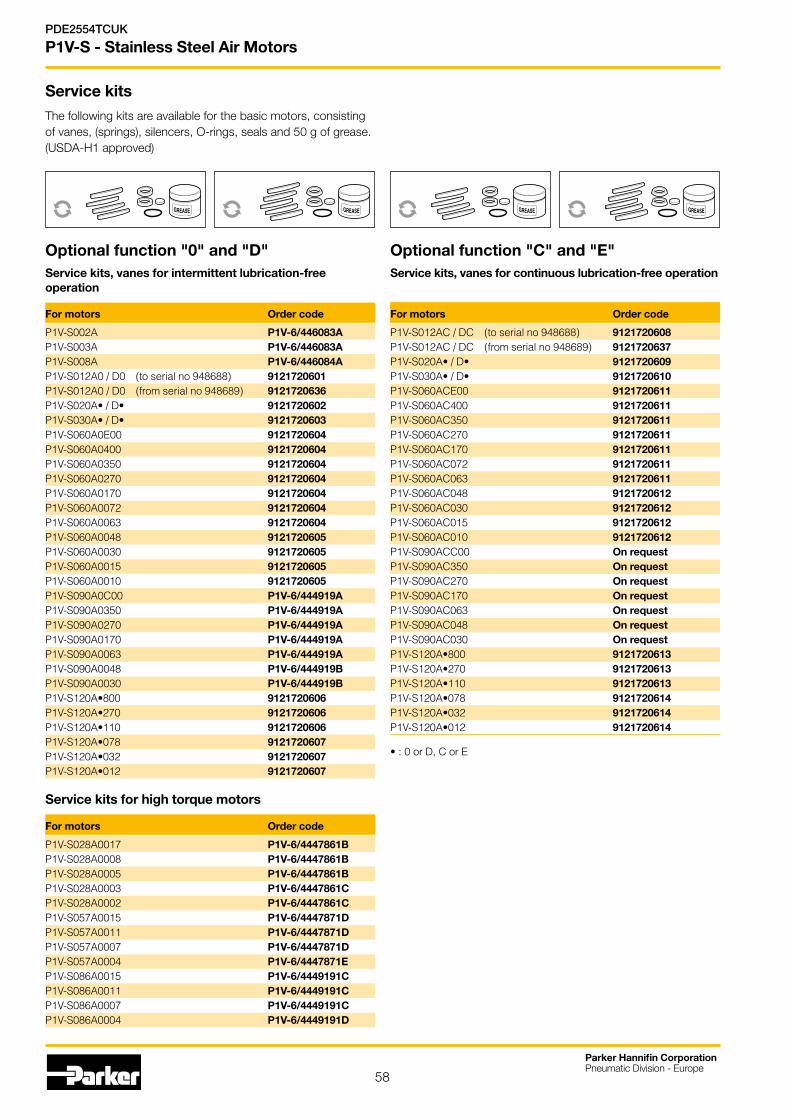
58
Parker Hannifin CorporationPneumatic Division - Europe
PDE2554TCUK
P1V-S - Stainless Steel Air Motors
Service kitsThe following kits are available for the basic motors, consistingof vanes, (springs), silencers, O-rings, seals and 50 g of grease. (USDA-H1 approved)
Service kits, vanes for continuous lubrication-free operation
For motors Order code
P1V-S012AC / DC (to serial no 948688) 9121720608P1V-S012AC / DC (from serial no 948689) 9121720637P1V-S020A• / D• 9121720609P1V-S030A• / D• 9121720610P1V-S060ACE00 9121720611P1V-S060AC400 9121720611P1V-S060AC350 9121720611P1V-S060AC270 9121720611P1V-S060AC170 9121720611P1V-S060AC072 9121720611P1V-S060AC063 9121720611P1V-S060AC048 9121720612P1V-S060AC030 9121720612P1V-S060AC015 9121720612P1V-S060AC010 9121720612P1V-S090ACC00 On requestP1V-S090AC350 On requestP1V-S090AC270 On requestP1V-S090AC170 On requestP1V-S090AC063 On requestP1V-S090AC048 On requestP1V-S090AC030 On requestP1V-S120A•800 9121720613P1V-S120A•270 9121720613P1V-S120A•110 9121720613P1V-S120A•078 9121720614P1V-S120A•032 9121720614P1V-S120A•012 9121720614
Optional function "0" and "D" Optional function "C" and "E"
• : 0 or D, C or E
Service kits, vanes for intermittent lubrication-free operation
For motors Order code
P1V-S002A P1V-6/446083AP1V-S003A P1V-6/446083AP1V-S008A P1V-6/446084AP1V-S012A0 / D0 (to serial no 948688) 9121720601P1V-S012A0 / D0 (from serial no 948689) 9121720636P1V-S020A• / D• 9121720602P1V-S030A• / D• 9121720603P1V-S060A0E00 9121720604P1V-S060A0400 9121720604P1V-S060A0350 9121720604P1V-S060A0270 9121720604P1V-S060A0170 9121720604P1V-S060A0072 9121720604P1V-S060A0063 9121720604P1V-S060A0048 9121720605P1V-S060A0030 9121720605P1V-S060A0015 9121720605P1V-S060A0010 9121720605P1V-S090A0C00 P1V-6/444919AP1V-S090A0350 P1V-6/444919AP1V-S090A0270 P1V-6/444919AP1V-S090A0170 P1V-6/444919AP1V-S090A0063 P1V-6/444919AP1V-S090A0048 P1V-6/444919BP1V-S090A0030 P1V-6/444919BP1V-S120A•800 9121720606P1V-S120A•270 9121720606P1V-S120A•110 9121720606P1V-S120A•078 9121720607P1V-S120A•032 9121720607P1V-S120A•012 9121720607
Service kits for high torque motors
For motors Order code
P1V-S028A0017 P1V-6/4447861BP1V-S028A0008 P1V-6/4447861BP1V-S028A0005 P1V-6/4447861BP1V-S028A0003 P1V-6/4447861CP1V-S028A0002 P1V-6/4447861CP1V-S057A0015 P1V-6/4447871DP1V-S057A0011 P1V-6/4447871DP1V-S057A0007 P1V-6/4447871DP1V-S057A0004 P1V-6/4447871EP1V-S086A0015 P1V-6/4449191CP1V-S086A0011 P1V-6/4449191CP1V-S086A0007 P1V-6/4449191CP1V-S086A0004 P1V-6/4449191D
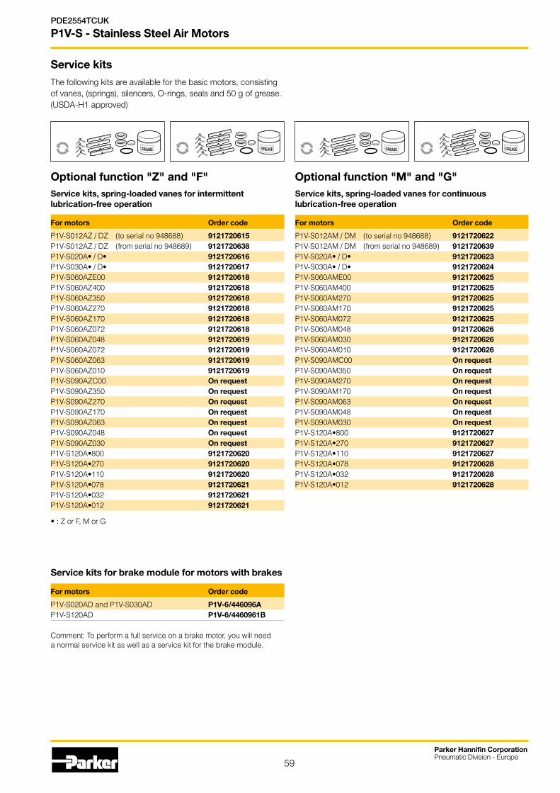
59
Parker Hannifin CorporationPneumatic Division - Europe
PDE2554TCUK
P1V-S - Stainless Steel Air Motors
Service kitsThe following kits are available for the basic motors, consistingof vanes, (springs), silencers, O-rings, seals and 50 g of grease. (USDA-H1 approved)
Service kits, spring-loaded vanes for intermittent lubrication-free operation
For motors Order code
P1V-S012AZ / DZ (to serial no 948688) 9121720615P1V-S012AZ / DZ (from serial no 948689) 9121720638P1V-S020A• / D• 9121720616P1V-S030A• / D• 9121720617P1V-S060AZE00 9121720618P1V-S060AZ400 9121720618P1V-S060AZ350 9121720618P1V-S060AZ270 9121720618P1V-S060AZ170 9121720618P1V-S060AZ072 9121720618P1V-S060AZ048 9121720619P1V-S060AZ072 9121720619P1V-S060AZ063 9121720619P1V-S060AZ010 9121720619P1V-S090AZC00 On requestP1V-S090AZ350 On requestP1V-S090AZ270 On requestP1V-S090AZ170 On requestP1V-S090AZ063 On requestP1V-S090AZ048 On requestP1V-S090AZ030 On requestP1V-S120A•800 9121720620P1V-S120A•270 9121720620P1V-S120A•110 9121720620P1V-S120A•078 9121720621P1V-S120A•032 9121720621P1V-S120A•012 9121720621
Service kits for brake module for motors with brakes
For motors Order code
P1V-S020AD and P1V-S030AD P1V-6/446096AP1V-S120AD P1V-6/4460961B
Comment: To perform a full service on a brake motor, you will need a normal service kit as well as a service kit for the brake module.
Service kits, spring-loaded vanes for continuous lubrication-free operation
For motors Order code
P1V-S012AM / DM (to serial no 948688) 9121720622P1V-S012AM / DM (from serial no 948689) 9121720639P1V-S020A• / D• 9121720623P1V-S030A• / D• 9121720624P1V-S060AME00 9121720625P1V-S060AM400 9121720625P1V-S060AM270 9121720625P1V-S060AM170 9121720625P1V-S060AM072 9121720625P1V-S060AM048 9121720626P1V-S060AM030 9121720626P1V-S060AM010 9121720626P1V-S090AMC00 On requestP1V-S090AM350 On requestP1V-S090AM270 On requestP1V-S090AM170 On requestP1V-S090AM063 On requestP1V-S090AM048 On requestP1V-S090AM030 On requestP1V-S120A•800 9121720627P1V-S120A•270 9121720627P1V-S120A•110 9121720627P1V-S120A•078 9121720628P1V-S120A•032 9121720628P1V-S120A•012 9121720628
Optional function "Z" and "F" Optional function "M" and "G"
• : Z or F, M or G
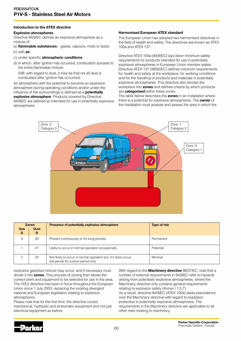
60
Parker Hannifin CorporationPneumatic Division - Europe
PDE2554TCUK
P1V-S - Stainless Steel Air Motors
Introduction to the ATEX directive
Explosive atmospheresDirective 94/9/EC defines an explosive atmosphere as a mixture of:a) flammable substances – gases, vapours, mists or dusts
b) with air
c) under specific atmospheric conditions
d) in which, after ignition has occurred, combustion spreads to the entire flammable mixture
(NB: with regard to dust, it may be that not all dust is combusted after ignition has occurred)
An atmosphere with the potential to become an explosive atmosphere during operating conditions and/or under the influence of the surroundings is defined as a potentially explosive atmosphere. Products covered by Directive 94/9/EC are defined as intended for use in potentially explosive atmospheres.
Harmonised European ATEX standardThe European Union has adopted two harmonised directives in the field of health and safety. The directives are known as ATEX 100a and ATEX 137.
Directive ATEX 100a (94/9/EC) lays down minimum safety requirements for products intended for use in potentially explosive atmospheres in European Union member states. Directive ATEX 137 (99/92/EC) defines minimum requirements for health and safety at the workplace, for working conditions and for the handling of products and materials in potentially explosive atmospheres. This directive also divides the workplace into zones and defines criteria by which products are categorised within these zones. The table below describes the zones in an installation where there is a potential for explosive atmospheres. The owner of the installation must analyse and assess the area in which the
explosive gas/dust mixture may occur, and if necessary must divide it into zones. This process of zoning then allows the correct plant and equipment to be selected for use in the area. The ATEX directive has been in force throughout the European Union since 1 July 2003, replacing the existing divergent national and European legislation relating to explosive atmospheres.Please note that for the first time, the directive covers mechanical, hydraulic and pneumatic equipment and not just electrical equipment as before.
With regard to the Machinery directive 98/37/EC, note that a number of external requirements in 94/9/EC refer to hazards arising from potentially explosive atmospheres, where the Machinery directive only contains general requirements relating to explosion safety (Annex I 1.5.7).As a result, directive 94/9/EC (ATEX 100a) takes precedence over the Machinery directive with regard to explosion protection in potentially explosive atmospheres. The requirements in the Machinery directive are applicable to all other risks relating to machinery.
Zone 1Category 2
Zone 2Category 3
Zone 0Category 1
Zones Presence of potentially explosive atmosphere Type of risk Gas Dust G D
0 20 Present continuously or for long periods Permanent
1 21 Likely to occur in normal operation occasionally Potential
2 22 Not likely to occur in normal operation but, if it does occur, Minimal will persist for a short period only
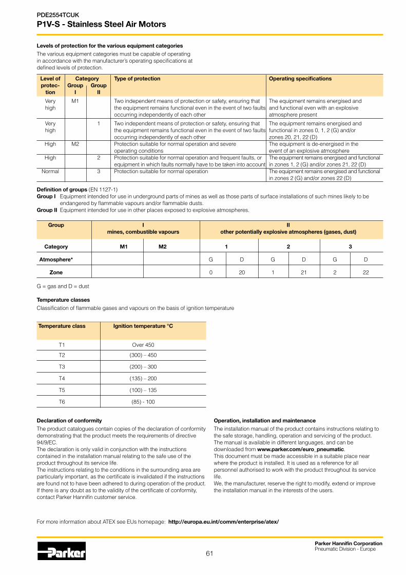
61
Parker Hannifin CorporationPneumatic Division - Europe
PDE2554TCUK
P1V-S - Stainless Steel Air Motors
Levels of protection for the various equipment categories
The various equipment categories must be capable of operating in accordance with the manufacturer’s operating specifications at defined levels of protection.
Level of Category Type of protection Operating specifications protec- Group Group tion I II
Very M1 Two independent means of protection or safety, ensuring that The equipment remains energised and high the equipment remains functional even in the event of two faults and functional even with an explosive occurring independently of each other atmosphere present
Very 1 Two independent means of protection or safety, ensuring that The equipment remains energised and high the equipment remains functional even in the event of two faults functional in zones 0, 1, 2 (G) and/or occurring independently of each other zones 20, 21, 22 (D) High M2 Protection suitable for normal operation and severe The equipment is de-energised in the operating conditions event of an explosive atmosphere High 2 Protection suitable for normal operation and frequent faults, or The equipment remains energised and functional equipment in which faults normally have to be taken into account in zones 1, 2 (G) and/or zones 21, 22 (D) Normal 3 Protection suitable for normal operation The equipment remains energised and functional in zones 2 (G) and/or zones 22 (D)
G = gas and D = dust
Temperature classes
Classification of flammable gases and vapours on the basis of ignition temperature
Group I II mines, combustible vapours other potentially explosive atmospheres (gases, dust)
Category M1 M2 1 2 3
Atmosphere* G D G D G D
Zone 0 20 1 21 2 22
Declaration of conformity
The product catalogues contain copies of the declaration of conformity demonstrating that the product meets the requirements of directive 94/9/EC.The declaration is only valid in conjunction with the instructions contained in the installation manual relating to the safe use of the product throughout its service life. The instructions relating to the conditions in the surrounding area are particularly important, as the certificate is invalidated if the instructions are found not to have been adhered to during operation of the product.If there is any doubt as to the validity of the certificate of conformity, contact Parker Hannifin customer service.
Temperature class Ignition temperature °C
T1 Over 450
T2 (300) – 450
T3 (200) – 300
T4 (135) – 200
T5 (100) – 135
T6 (85) - 100
Operation, installation and maintenance
The installation manual of the product contains instructions relating to the safe storage, handling, operation and servicing of the product.The manual is available in different languages, and can be downloaded from www.parker.com/euro_pneumatic.This document must be made accessible in a suitable place near where the product is installed. It is used as a reference for all personnel authorised to work with the product throughout its service life. We, the manufacturer, reserve the right to modify, extend or improve the installation manual in the interests of the users.
For more information about ATEX see EUs homepage: http://europa.eu.int/comm/enterprise/atex/
Definition of groups (EN 1127-1)Group I Equipment intended for use in underground parts of mines as well as those parts of surface installations of such mines likely to be
endangered by flammable vapours and/or flammable dusts.Group II Equipment intended for use in other places exposed to explosive atmospheres.
62
Parker Hannifin CorporationPneumatic Division - Europe
PDE2554TCUK
P1V-S - Stainless Steel Air Motors
Serious, even fatal, damage or injury may be caused by the hot moving parts of the P1V-S motors in the presence of explosive gas mixtures and concentrations of dust.
All installation, connection, commissioning, servicing and repair work on P1V-S motors must be carried out by qualified personnel taking account of the following• These instructions
• Notices on the motor
• All other planning documents, commissioning instructions and connection diagrams associated with the application.
• Provisions and requirements specific to the application
• Applicable national/international regulations (explosion protection, safety and accident prevention)
Real life applicationsP1V-S motors are designed to provide rotary movement in industrial applications, and should only be used in accordance with the instruc-tions in the technical specifications in the catalogue, and within the operating range indicated on the motor housing. The motors meet the applicable standards and requirements of the Machinery Directive 94/9/EC (ATEX)
The motors must not be used as brakes in explosive atmospheres. Braking involves driving the motor against the direction of rotation for which the motor is supplied with compressed air. The motor is then operating as a compressor, and there is a corresponding increase in temperature.
The motors must not be used underground in mines susceptible to firedamp and/or combustible dust. The motors are intended for use in areas in which explosive atmospheres caused by gases, vapours or mists of combustible liquids, or air/dust mixtures may be expected to occur during normal use (infrequently)
Checklist Before using the motors in a potentially explosive atmosphere, you should check the following:
Do the motor specifications match the classification of the area of use in accordance with Directive 94/9/EG (previously ATEX 100a)
• Equipment group
• Equipment category
• Zone
• Temperature class
• Max. surface temperature
1. When installing the motor, is it certain that there is no potentially explosive atmosphere, oil, acids, gases, vapours or radiation?
2. Is the ambient temperature as specified in the technical data in the catalogue at all times?
3. Is it certain that the P1V-S motor is adequately ventilated and that no additional heat is added (for example in the shaft connection)?
4. Are all the driven mechanical components ATEX certified?
Additional safety instructions for installation in explosive atmospheres
Installation requirements in potentially explosive atmospheres• The temperature of the supply air must not exceed the ambient
temperature.
• The P1V-S may be installed in any position.
• An air treatment unit must be attached to the inlet of the P1V-S air motor.
• In a potentially explosive atmosphere, none of the motor ports may be blocked because this may cause an increase in temperature. The air from the port must be taken to the silencer or, preferably, outside the potentially explosive area.
• The P1V-S motor must be connected to ground at all times, through its support, a metallic tube or separate conductor.
• The outlet of the P1V-S motor must not open within a potentially explosive area, but must be passed to the silencer or, preferably, removed and released outside the potentially explosive area.
• The P1V-S motor may only drive units that are ATEX certified.
• Ensure that the motor is not exposed to forces greater than those permitted in accordance with the catalogue.
Measuring the temperature on the outside of the P1V-S motor (only when used in potentially explosive areas)During the commissioning process, it is essential to measure tempera-ture increases at the indicated positions on the outside of the P1V-S motor.These measurements can be taken using standard thermometers.
Checking the motor during operationThe motor must be kept clean on the outside, and a layer of dirt thicker than 5 mm must never be allowed to form.Strong solvents should not be used for cleaning, because they can cause the seal (material NBR/FPM) around the drive shaft to swell, potentially increasing the temperature.
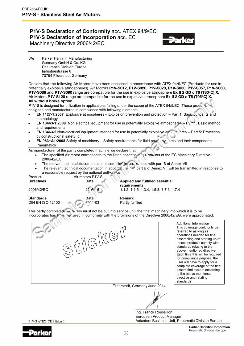
63
Parker Hannifin CorporationPneumatic Division - Europe
PDE2554TCUK
P1V-S - Stainless Steel Air Motors
P1V-S ATEX_CE Edition 01
P1V-S Declaration of Conformity acc. ATEX 94/9/EC P1V-S Declaration of Incorporation acc. EC Machinery Directive 2006/42/EC
We Parker Hannifin ManufacturingGermany GmbH & Co. KG
Pneumatic Division Europe Industriestrasse 8 70794 Filderstadt Germany
Declare that the following Air Motors have been assessed in accordance with ATEX 94/9/EC (Products for use in potentially explosive atmospheres). Air Motors P1V-S012, P1V-S020, P1V-S028, P1V-S030, P1V-S057, P1V-S060,P1V-S086 and P1V-S090 range are compatible for the use in explosive atmosphere Ex II 2 GD c T6 (T80°C) X. Air Motors P1V-S120 range are compatible for the use in explosive atmosphere Ex II 2 GD c T5 (T95°C) X. All without brake option. P1V-S is designed for utilization in applications falling under the scope of the ATEX 94/9/EC. These products are designed and manufactured in compliance with following elements: EN 1127-1:2007 Explosive atmospheres – Explosion prevention and protection – Part 1: Basic concepts and
methodology EN 13463-1:2009 Non electrical equipment for use in potentially explosive atmospheres – Part 1: Basic method
and requirements EN 13463-5 Non-electrical equipment intended for use in potentially explosive atmospheres – Part 5: Protection
by constructional safety ´c´ EN 983+A1:2008 Safety of machinery – Safety requirements for fluid power systems and their components -
PneumaticsAs manufacturer of the partly completed machine we declare that:
The specified Air motor corresponds to the listed essential requirements of the EC Machinery Directive 2006/42/EC
The relevant technical documentation is complied in accordance with part B of Annex VII The relevant technical documentation in accordance with part B of Annex VII will be transmitted in response to
a reasonable request by the national authorities Product: Pneumatic Air motors P1V-S Directives Date Applied and fulfilled essential
requirements2006/42/EC 2006-06 1.1.2, 1.1.5, 1.3.4, 1.5.3, 1.7.3, 1.7.4
Standards Date RemarkDIN EN ISO 12100 2011-03 Partly fulfilled
This partly completed machinery must not be put into service until the final machinery into which it is to be incorporates has been declared in conformity with the provisions of the Directive 2006/42/EG, were appropriated.
Filderstadt, Germany June 2014
_______________________________________ Ing. Franck Roussillon European Product Manager Actuators Business Unit, Pneumatic Division Europe
Additional InformationThis coverage could only be referred to as long as operations needed for final assembling and starting up of theses products comply with standards relating to the above mentioned directive. Each time this will be required for compliance purpose, the user will have to apply for a complete coverage of the final assembled system according to the above mentioned directive and relating standards
Declare that the following Air Motors have been assessed in accordance with ATEX 94/9/EC (Products for use inpotentially explosive atmospheres). Air Motors P1V-S012, P1V-S020, P1V-S028, P1V-S030, P1V-S057, P1V-S060, P1V-S086 and P1V-S090 range are compatible for the use in explosive atmosphere Ex II 2 GD c T6 (T80OC) X. Air Motors P1V-S120 range are compatible for the use in explosive atmosphere Ex II 2 GD c T5 (T95OC) X.All without brake option.
Sample, for in
formatio
n only
64
Parker Hannifin CorporationPneumatic Division - Europe
PDE2554TCUK
P1V-S - Stainless Steel Air Motors
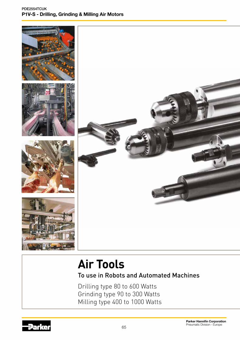
65
Parker Hannifin CorporationPneumatic Division - Europe
PDE2554TCUK
P1V-S - Drilling, Grinding & Milling Air Motors
Air Tools
Drilling type 80 to 600 WattsGrinding type 90 to 300 WattsMilling type 400 to 1000 Watts
To use in Robots and Automated Machines
66
Parker Hannifin CorporationPneumatic Division - Europe
PDE2554TCUK
P1V-S - Drilling, Grinding & Milling Air Motors
Contents Page
Introduction ................................................................................................. 67Order model code ....................................................................................... 67Technical data ............................................................................................. 68Material specification ................................................................................... 68Permitted shaft loadings .............................................................................. 69
Drilling motor with collet 80 watts ................................................................ 70Dimensions .................................................................................................. 70Drilling motor with collet 170 watts .............................................................. 71Dimensions .................................................................................................. 71Drilling motor for drill chuck 170 watts ......................................................... 72Dimensions .................................................................................................. 72Drilling motor with collet 250 watts .............................................................. 73Dimensions .................................................................................................. 73Drilling motor for drill chuck 250 watts ......................................................... 74Dimensions .................................................................................................. 74Drilling motor for drill chuck 400 watts ......................................................... 75Dimensions .................................................................................................. 75Drilling motor for drill chuck 600 watts ......................................................... 76Dimensions .................................................................................................. 76
Mounting for drilling motors ......................................................................... 77
Grinding motor with collet 90 watts ............................................................. 78Grinding motor with collet 150 watts ........................................................... 79Grinding motor with collet 250 watts ........................................................... 79Grinding motor with collet 300 watts ........................................................... 79
Milling motor with collet 400 watts ............................................................... 80Milling motor with collet 500 watts ............................................................... 81Milling motor with collet 700 watts ............................................................... 81Milling motor with collet 1000 watts ............................................................. 81Dimensions .................................................................................................. 81
Lubrication and service life ........................................................................... 82Service kits .................................................................................................. 82
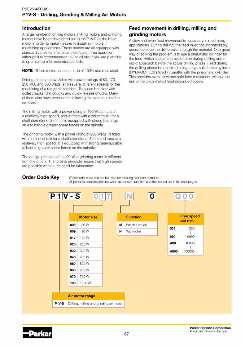
67
Parker Hannifin CorporationPneumatic Division - Europe
PDE2554TCUK
P1V-S - Drilling, Grinding & Milling Air Motors
P 1 V - S 0 1 7 N 0 Q 0 0
Order Code Key (This model code can not be used for creating new part numbers. All possible combinations between motor size, function and free speed are in the next pages).
Function
M For drill chuck
N With collet
Motor size
008 80 W
009 90 W
017 170 W
025 250 W
030 300 W
040 400 W
050 500 W
060 600 W
070 700 W
100 1000 W
Free speed per min
035 350 999 9990
A00 10000 A000 100000
Air motor range
P1V-S Drilling, milling and grinding air motor
IntroductionA large number of drilling motors, milling motors and grinding motors have been developed using the P1V-S as the base motor in order to make it easier to install air motors in machining applications. These motors are all equipped with standard vanes for intermittent lubrication-free operation, although it is recommended to use oil mist if you are planning to operate them for extended periods.
NOTE! These motors are not made of 100% stainless steel.
Drilling motors are available with power ratings of 80, 170, 250, 400 and 600 Watts, and several different speeds for the machining of a range of materials. They can be fitted with collet chucks, drill chucks and quick-release chucks. Many of them also have accessories allowing the exhaust air to be removed.
The milling motor, with a power rating of 400 Watts, runs at a relatively high speed, and is fitted with a collet chuck for a shaft diameter of 8 mm. It is equipped with strong bearings able to handle greater shear forces on the spindle.
The grinding motor, with a power rating of 200 Watts, is fitted with a collet chuck for a shaft diameter of 8 mm and runs at a relatively high speed. It is equipped with strong bearings able to handle greater shear forces on the spindle.
The design principle of the 90 Watt grinding motor is different from the others. The turbine principle means that high speeds are possible without the need for lubrication.
Feed movement in drilling, milling and grinding motorsA slow and even feed movement is necessary in machining applications. During drilling, the feed must not uncontrollably speed up once the drill breaks through the material. One good way of solving the problem is to use a pneumatic cylinder for the feed, which is able to provide force during drilling and a rapid approach before the actual drilling phase. Feed during the drilling phase is controlled using a hydraulic brake cylinder (HYDROCHECK) fitted in parallel with the pneumatic cylinder. This provides even, slow and safe feed movement, without the risk of the uncontrolled feed described above.
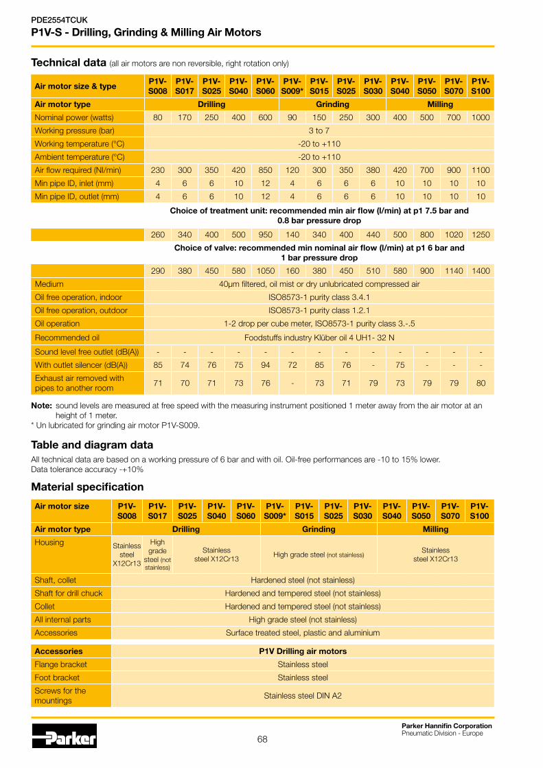
68
Parker Hannifin CorporationPneumatic Division - Europe
PDE2554TCUK
P1V-S - Drilling, Grinding & Milling Air Motors
Air motor size & typeP1V-S008
P1V-S017
P1V-S025
P1V-S040
P1V-S060
P1V-S009*
P1V-S015
P1V-S025
P1V-S030
P1V-S040
P1V-S050
P1V-S070
P1V-S100
Air motor type Drilling Grinding Milling
Nominal power (watts) 80 170 250 400 600 90 150 250 300 400 500 700 1000
Working pressure (bar) 3 to 7
Working temperature (°C) -20 to +110
Ambient temperature (°C) -20 to +110
Air flow required (NI/min) 230 300 350 420 850 120 300 350 380 420 700 900 1100
Min pipe ID, inlet (mm) 4 6 6 10 12 4 6 6 6 10 10 10 10
Min pipe ID, outlet (mm) 4 6 6 10 12 4 6 6 6 10 10 10 10
Choice of treatment unit: recommended min air flow (l/min) at p1 7.5 bar and 0.8 bar pressure drop
260 340 400 500 950 140 340 400 440 500 800 1020 1250
Choice of valve: recommended min nominal air flow (l/min) at p1 6 bar and 1 bar pressure drop
290 380 450 580 1050 160 380 450 510 580 900 1140 1400
Medium 40µm filtered, oil mist or dry unlubricated compressed air
Oil free operation, indoor ISO8573-1 purity class 3.4.1
Oil free operation, outdoor ISO8573-1 purity class 1.2.1
Oil operation 1-2 drop per cube meter, ISO8573-1 purity class 3.-.5
Recommended oil Foodstuffs industry Klüber oil 4 UH1- 32 N
Sound level free outlet (dB(A)) - - - - - - - - - - - - -
With outlet silencer (dB(A)) 85 74 76 75 94 72 85 76 - 75 - - -
Exhaust air removed with pipes to another room
71 70 71 73 76 - 73 71 79 73 79 79 80
Technical data (all air motors are non reversible, right rotation only)
Note: sound levels are measured at free speed with the measuring instrument positioned 1 meter away from the air motor at an height of 1 meter.* Un lubricated for grinding air motor P1V-S009.
Table and diagram dataAll technical data are based on a working pressure of 6 bar and with oil. Oil-free performances are -10 to 15% lower. Data tolerance accuracy -+10%
Material specification
Air motor size P1V-S008
P1V-S017
P1V-S025
P1V-S040
P1V-S060
P1V-S009*
P1V-S015
P1V-S025
P1V-S030
P1V-S040
P1V-S050
P1V-S070
P1V-S100
Air motor type Drilling Grinding Milling
Housing Stainlesssteel
X12Cr13
High grade
steel (not stainless)
Stainlesssteel X12Cr13
High grade steel (not stainless)Stainless
steel X12Cr13
Shaft, collet Hardened steel (not stainless)
Shaft for drill chuck Hardened and tempered steel (not stainless)
Collet Hardened and tempered steel (not stainless)
All internal parts High grade steel (not stainless)
Accessories Surface treated steel, plastic and aluminium
Accessories P1V Drilling air motors
Flange bracket Stainless steel
Foot bracket Stainless steel
Screws for the mountings
Stainless steel DIN A2
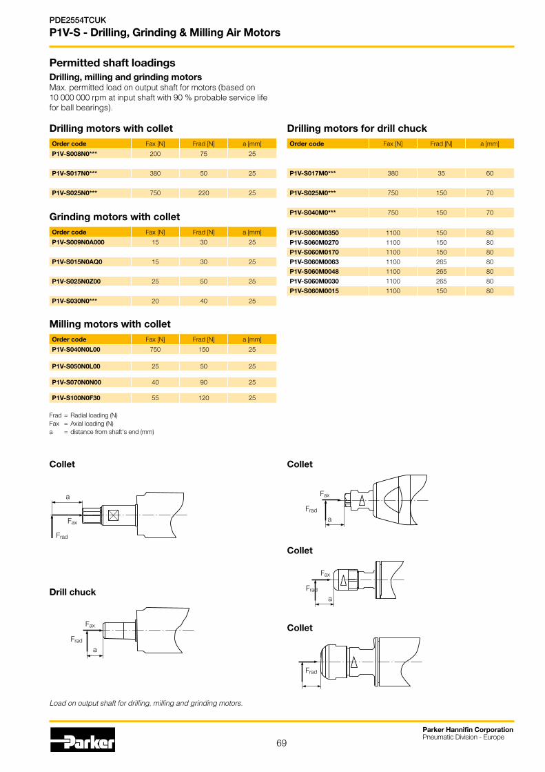
69
Parker Hannifin CorporationPneumatic Division - Europe
PDE2554TCUK
P1V-S - Drilling, Grinding & Milling Air Motors
Frad
Fax
a
Frad
Fax
a
Frad
Fax
a
Collet
Collet
Load on output shaft for drilling, milling and grinding motors.
Frad
Fax
a
Collet
Frad
Fax
a
Drill chuck
Collet
Order code Fax [N] Frad [N] a [mm]
P1V-S017M0*** 380 35 60
P1V-S025M0*** 750 150 70
P1V-S040M0*** 750 150 70
P1V-S060M0350 1100 150 80
P1V-S060M0270 1100 150 80
P1V-S060M0170 1100 150 80
P1V-S060M0063 1100 265 80
P1V-S060M0048 1100 265 80
P1V-S060M0030 1100 265 80
P1V-S060M0015 1100 150 80
Drilling motors for drill chuckOrder code Fax [N] Frad [N] a [mm]
P1V-S008N0*** 200 75 25
P1V-S017N0*** 380 50 25
P1V-S025N0*** 750 220 25
Frad = Radial loading (N)Fax = Axial loading (N)a = distance from shaft's end (mm)
Drilling motors with collet
Permitted shaft loadingsDrilling, milling and grinding motorsMax. permitted load on output shaft for motors (based on 10 000 000 rpm at input shaft with 90 % probable service life for ball bearings).
Order code Fax [N] Frad [N] a [mm]
P1V-S009N0A000 15 30 25
P1V-S015N0AQ0 15 30 25
P1V-S025N0Z00 25 50 25
P1V-S030N0*** 20 40 25
Grinding motors with collet
Order code Fax [N] Frad [N] a [mm]
P1V-S040N0L00 750 150 25
P1V-S050N0L00 25 50 25
P1V-S070N0N00 40 90 25
P1V-S100N0F30 55 120 25
Milling motors with collet
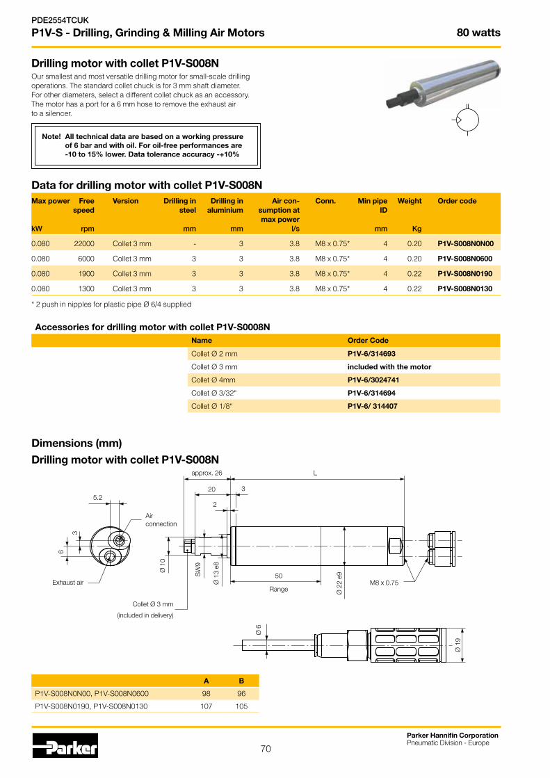
70
Parker Hannifin CorporationPneumatic Division - Europe
PDE2554TCUK
P1V-S - Drilling, Grinding & Milling Air Motors
Dimensions (mm)
Note! All technical data are based on a working pressure of 6 bar and with oil. For oil-free performances are -10 to 15% lower. Data tolerance accuracy -+10%
Abluftschlauchsystem Bestell-Nr. 302923 A (Optionales Zubehör)Zugehörige Abluftfilter Bestell-Nr. 811091
47 2214
G 1
/2
ca. 2 m
Zuluft
Abluft
G 1
/4
Spannzange ø 6 mm(Normalzubehör)
22 118-Spannbereich154ca. 33
ca. 59
ø 30
Spindel mitBohrfutterkegel B10 DIN238
Bohrfutter 0,5 - 6,5 mmBestell-Nr. 804655(Optionales Zubehör)
ø 25
d10
ø 12
Motorgröße 2Baureihe 104-rechtslaufend
Zuluft
G 1
/4
Abmessungen in mm
Exhaust air
Collet Ø 3 mm
(included in delivery)
Airconnection
5.2
6
3
Ø 1
0
Ø 1
3 e8
SW
9
Ø 2
2 e9
Ø 6
Ø 1
9
approx. 26 L
M8 x 0.7550
Range
20 3
2
Drilling motor with collet P1V-S008N
80 watts
Drilling motor with collet P1V-S008NOur smallest and most versatile drilling motor for small-scale drilling operations. The standard collet chuck is for 3 mm shaft diameter. For other diameters, select a different collet chuck as an accessory. The motor has a port for a 6 mm hose to remove the exhaust air to a silencer.
Max power Free Version Drilling in Drilling in Air con- Conn. Min pipe Weight Order code speed steel aluminium sumption at ID max power kW rpm mm mm l/s mm Kg
0.080 22000 Collet 3 mm - 3 3.8 M8 x 0.75* 4 0.20 P1V-S008N0N00
0.080 6000 Collet 3 mm 3 3 3.8 M8 x 0.75* 4 0.20 P1V-S008N0600
0.080 1900 Collet 3 mm 3 3 3.8 M8 x 0.75* 4 0.22 P1V-S008N0190
0.080 1300 Collet 3 mm 3 3 3.8 M8 x 0.75* 4 0.22 P1V-S008N0130
* 2 push in nipples for plastic pipe Ø 6/4 supplied
Accessories for drilling motor with collet P1V-S0008NName Order Code
Collet Ø 2 mm P1V-6/314693
Collet Ø 3 mm included with the motor
Collet Ø 4mm P1V-6/3024741
Collet Ø 3/32" P1V-6/314694
Collet Ø 1/8“ P1V-6/ 314407
A B
P1V-S008N0N00, P1V-S008N0600 98 96
P1V-S008N0190, P1V-S008N0130 107 105
Data for drilling motor with collet P1V-S008N
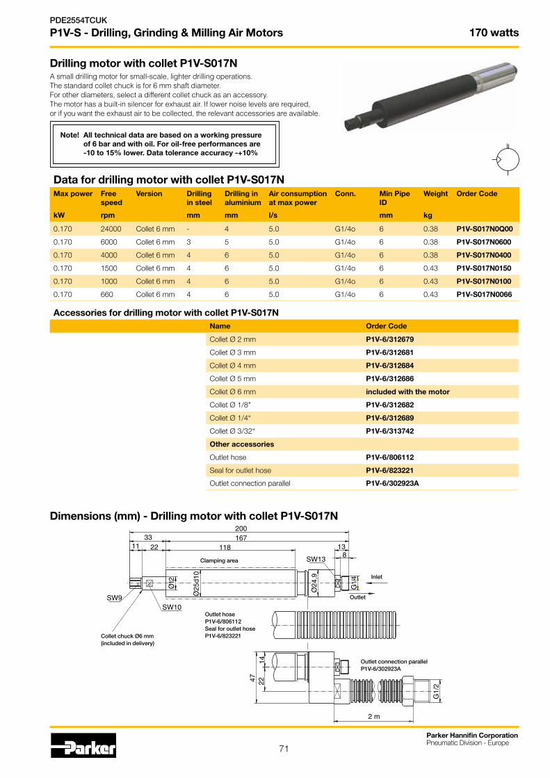
71
Parker Hannifin CorporationPneumatic Division - Europe
PDE2554TCUK
P1V-S - Drilling, Grinding & Milling Air Motors
Drilling motor with collet P1V-S017NA small drilling motor for small-scale, lighter drilling operations. The standard collet chuck is for 6 mm shaft diameter. For other diameters, select a different collet chuck as an accessory.The motor has a built-in silencer for exhaust air. If lower noise levels are required, or if you want the exhaust air to be collected, the relevant accessories are available.
Note! All technical data are based on a working pressure of 6 bar and with oil. For oil-free performances are -10 to 15% lower. Data tolerance accuracy -+10%
Dimensions (mm) - Drilling motor with collet P1V-S017N200167
11833
2211
SW9SW10
Ø12
Ø25
d10
SW13
138
G1/
4
Ø24
,9
1447 22
2 m
G1/
2
Clamping area
Collet chuck Ø6 mm(included in delivery)
Inlet
Outlet
Outlet hose P1V-6/806112Seal for outlet hose P1V-6/823221
Outlet connection parallel P1V-6/302923A
170 watts
Accessories for drilling motor with collet P1V-S017NName Order Code
Collet Ø 2 mm P1V-6/312679
Collet Ø 3 mm P1V-6/312681
Collet Ø 4 mm P1V-6/312684
Collet Ø 5 mm P1V-6/312686
Collet Ø 6 mm included with the motor
Collet Ø 1/8" P1V-6/312682
Collet Ø 1/4“ P1V-6/312689
Collet Ø 3/32“ P1V-6/313742
Other accessories
Outlet hose P1V-6/806112
Seal for outlet hose P1V-6/823221
Outlet connection parallel P1V-6/302923A
Data for drilling motor with collet P1V-S017NMax power Free
speedVersion Drilling
in steelDrilling in aluminium
Air consumption at max power
Conn. Min Pipe ID
Weight Order Code
kW rpm mm mm l/s mm kg
0.170 24000 Collet 6 mm - 4 5.0 G1/4o 6 0.38 P1V-S017N0Q00
0.170 6000 Collet 6 mm 3 5 5.0 G1/4o 6 0.38 P1V-S017N0600
0.170 4000 Collet 6 mm 4 6 5.0 G1/4o 6 0.38 P1V-S017N0400
0.170 1500 Collet 6 mm 4 6 5.0 G1/4o 6 0.43 P1V-S017N0150
0.170 1000 Collet 6 mm 4 6 5.0 G1/4o 6 0.43 P1V-S017N0100
0.170 660 Collet 6 mm 4 6 5.0 G1/4o 6 0.43 P1V-S017N0066
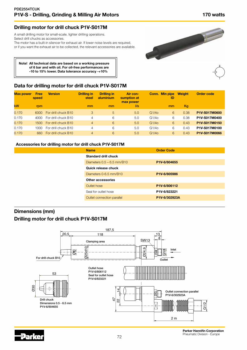
72
Parker Hannifin CorporationPneumatic Division - Europe
PDE2554TCUK
P1V-S - Drilling, Grinding & Milling Air Motors
Note! All technical data are based on a working pressure of 6 bar and with oil. For oil-free performances are -10 to 15% lower. Data tolerance accuracy -+10%
Drilling motor for drill chuck P1V-S017M
187,511820,5
Ø10
Ø25
d10
SW13
138
G1/
4
Ø24
,9
1447 22
2 m
G1/
2
53
Ø30
Clamping area
Inlet
Outlet
Outlet hose P1V-6/806112Seal for outlet hose P1V-6/823221
Outlet connection parallel P1V-6/302923A
Drill chuck Dimensions 0.5 - 6.5 mmP1V-6/804655
For drill chuck B10
Dimensions (mm)
170 watts
Drilling motor for drill chuck P1V-S017MA small drilling motor for small-scale, lighter drilling operations. Select drill chucks as accessories.The motor has a built-in silencer for exhaust air. If lower noise levels are required, or if you want the exhaust air to be collected, the relevant accessories are available.
Data for drilling motor for drill chuck P1V-S017M
Max power Free Version Drilling in Drilling in Air con- Conn. Min pipe Weight Order code speed steel aluminium sumption at ID max power kW rpm mm mm l/s mm Kg
0.170 6000 For drill chuck B10 3 5 5.0 G1/4o 6 0.38 P1V-S017M0600
0.170 4000 For drill chuck B10 4 6 5.0 G1/4o 6 0.38 P1V-S017M0400
0.170 1500 For drill chuck B10 4 6 5.0 G1/4o 6 0.43 P1V-S017M0150
0.170 1000 For drill chuck B10 4 6 5.0 G1/4o 6 0.43 P1V-S017M0100
0.170 660 For drill chuck B10 4 6 5.0 G1/4o 6 0.43 P1V-S017M0066
Accessories for drilling motor for drill chuck P1V-S017MName Order Code
Standard drill chuck
Diameters 0.5 – 6.5 mm/B10 P1V-6/804655
Quick release chuck
Diameters 0-6.5 mm/B10 P1V-6/805986
Other accessories
Outlet hose P1V-6/806112
Seal for outlet hose P1V-6/823221
Outlet connection parallel P1V-6/302923A
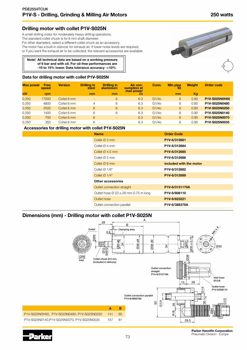
73
Parker Hannifin CorporationPneumatic Division - Europe
PDE2554TCUK
P1V-S - Drilling, Grinding & Milling Air Motors
G1/4
SW
9
Ø12
SW
10
0,85
28A
B
Ø38
e8
Ø38
d9
34
34
SW17
M35
x 0
,75
M4
x 4
Ø30
Ø38
15 28
Ø20
e8
G1/
2
G1/
4
62
26R
18
29,5
Ø25
G1/
430
Clamping area
Inlet
Outlet
Collet chuck Ø 6 mm(included in delivery)
Outlet connection straight P1V-6/313179A
Inlet hoseØ12/6
Outlet hoseP1V-6/806110
Outlet connection parallelP1V-6/388378A
Drilling motor with collet P1V-S025NA small drilling motor for moderately heavy drilling operations. The standard collet chuck is for 6 mm shaft diameter. For other diameters, select a different collet chuck as an accessory.The motor has a built-in silencer for exhaust air. If lower noise levels are required, or if you want the exhaust air to be collected, the relevant accessories are available.
Note! All technical data are based on a working pressure of 6 bar and with oil. For oil-free performances are -10 to 15% lower. Data tolerance accuracy -+10%
250 watts
Dimensions (mm) - Drilling motor with collet P1V-S025N
Data for drilling motor with collet P1V-S025N
Max power Free Version Drilling in Drilling in Air con- Conn. Min pipe Weight Order code speed steel aluminium sumption at ID max power kW rpm mm mm l/s mm Kg
0.250 17000 Collet 6 mm - 6 6.3 G1/4o 6 0.80 P1V-S025N0H000.250 4800 Collet 6 mm 4 6 6.3 G1/4o 6 0.80 P1V-S025N04800.250 2500 Collet 6 mm 6 6 6.3 G1/4o 6 0.80 P1V-S025N02500.250 1400 Collet 6 mm 6 6 6.3 G1/4o 6 0.90 P1V-S025N01400.250 700 Collet 6 mm 6 - 6.3 G1/4o 6 0.90 P1V-S025N00700.250 350 Collet 6 mm 6 - 6.3 G1/4o 6 0.90 P1V-S025N0035
Accessories for drilling motor with collet P1V-S025NName Order Code
Collet Ø 3 mm P1V-6/312681
Collet Ø 4 mm P1V-6/312684
Collet Ø 4.5 mm P1V-6/312685
Collet Ø 5 mm P1V-6/312686
Collet Ø 6 mm included with the motor
Collet Ø 1/8" P1V-6/312682
Collet Ø 1/4“ P1V-6/312689
Other accessories
Outlet connection straight P1V-6/3131179A
Outlet hose Ø 23 x 28 mm 0.75 m long P1V-6/806110
Outlet hose P1V-6/823221
Outlet connection parallel P1V-6/388378A
A B
P1V-S025N0H00, P1V-S025N0480, P1V-S025N0250 141 65
P1V-S025N0140,P1V-S025N0070, P1V-S025N0035 157 81
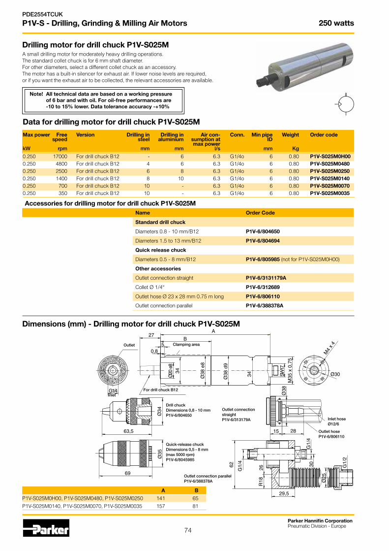
74
Parker Hannifin CorporationPneumatic Division - Europe
PDE2554TCUK
P1V-S - Drilling, Grinding & Milling Air Motors
Dimensions (mm) - Drilling motor for drill chuck P1V-S025M
G1/4
0,85
27A
B
Ø38
e8
Ø38
d9
34
34
SW17
M35
x 0
,75
M4
x 4
Ø30
Ø38
15 28
Ø20
e8
G1/
2
G1/
4
62
26R
18
29,5
Ø25
G1/
430
63,5
69
Ø34
Ø35
Clamping area
Inlet
Outlet
Outlet connection straight P1V-6/313179A
Outlet hose P1V-6/806110
Inlet hose Ø12/6
For drill chuck B12
Drill chuck Dimensions 0,8 - 10 mmP1V-6/804650
Outlet connection parallelP1V-6/388378A
Quick-release chuckDimensions 0,5 - 8 mm(max 5000 rpm)P1V-6/8045985
Note! All technical data are based on a working pressure of 6 bar and with oil. For oil-free performances are -10 to 15% lower. Data tolerance accuracy -+10%
250 watts
A B
P1V-S025M0H00, P1V-S025M0480, P1V-S025M0250 141 65P1V-S025M0140, P1V-S025M0070, P1V-S025M0035 157 81
Drilling motor for drill chuck P1V-S025MA small drilling motor for moderately heavy drilling operations. The standard collet chuck is for 6 mm shaft diameter. For other diameters, select a different collet chuck as an accessory.The motor has a built-in silencer for exhaust air. If lower noise levels are required, or if you want the exhaust air to be collected, the relevant accessories are available.
Data for drilling motor for drill chuck P1V-S025M
Max power Free Version Drilling in Drilling in Air con- Conn. Min pipe Weight Order code speed steel aluminium sumption at ID max power kW rpm mm mm l/s mm Kg
0.250 17000 For drill chuck B12 - 6 6.3 G1/4o 6 0.80 P1V-S025M0H000.250 4800 For drill chuck B12 4 6 6.3 G1/4o 6 0.80 P1V-S025M04800.250 2500 For drill chuck B12 6 8 6.3 G1/4o 6 0.80 P1V-S025M02500.250 1400 For drill chuck B12 8 10 6.3 G1/4o 6 0.80 P1V-S025M01400.250 700 For drill chuck B12 10 - 6.3 G1/4o 6 0.80 P1V-S025M00700.250 350 For drill chuck B12 10 - 6.3 G1/4o 6 0.80 P1V-S025M0035
Accessories for drilling motor for drill chuck P1V-S025MName Order Code
Standard drill chuck
Diameters 0.8 - 10 mm/B12 P1V-6/804650
Diameters 1.5 to 13 mm/B12 P1V-6/804694
Quick release chuck
Diameters 0.5 - 8 mm/B12 P1V-6/805985 (not for P1V-S025M0H00)
Other accessories
Outlet connection straight P1V-6/3131179A
Collet Ø 1/4“ P1V-6/312689
Outlet hose Ø 23 x 28 mm 0.75 m long P1V-6/806110
Outlet connection parallel P1V-6/388378A
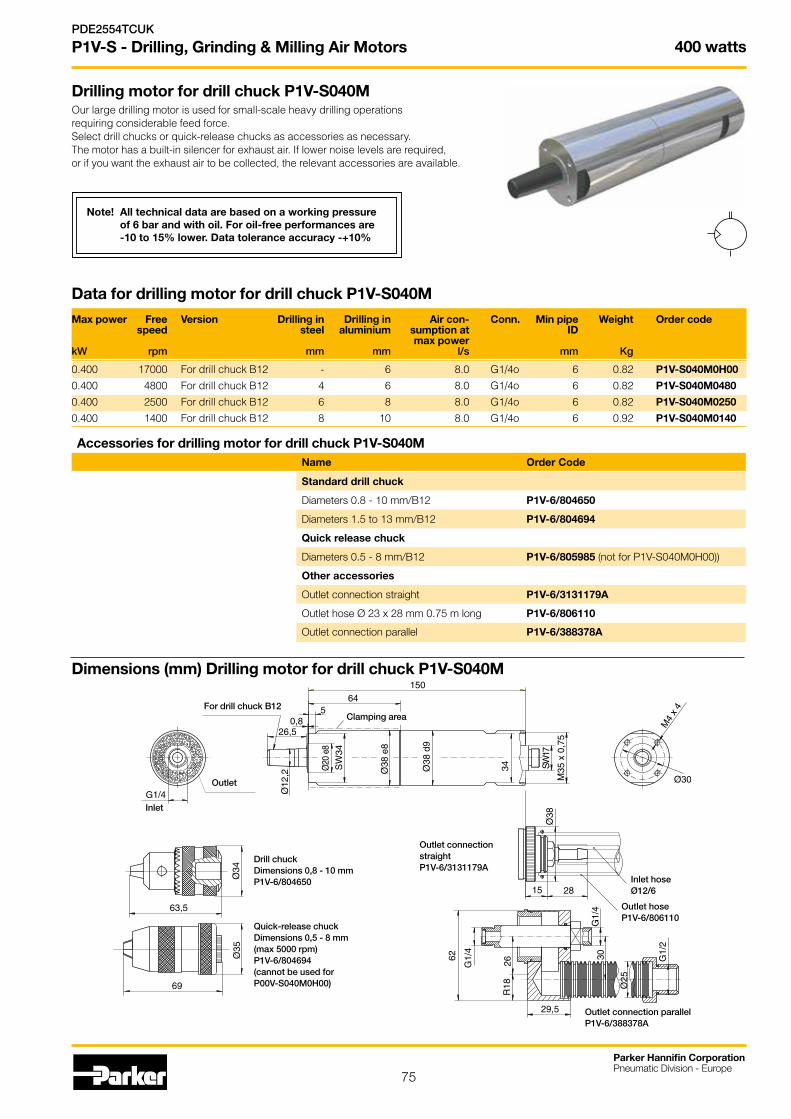
75
Parker Hannifin CorporationPneumatic Division - Europe
PDE2554TCUK
P1V-S - Drilling, Grinding & Milling Air Motors
Drilling motor for drill chuck P1V-S040MOur large drilling motor is used for small-scale heavy drilling operations requiring considerable feed force.Select drill chucks or quick-release chucks as accessories as necessary.The motor has a built-in silencer for exhaust air. If lower noise levels are required, or if you want the exhaust air to be collected, the relevant accessories are available.
Note! All technical data are based on a working pressure of 6 bar and with oil. For oil-free performances are -10 to 15% lower. Data tolerance accuracy -+10%
Dimensions (mm) Drilling motor for drill chuck P1V-S040M
0,85
64150
Ø12
,2
Ø20
e8
SW
34
Ø38
e8
Ø38
d9
34 SW17
G1/4
M35
x 0
,75
M4
x4
Ø30
G1/
2
G1/
4
62
26R
18
29,5
63,5
69 Ø25
26,5
Ø38
Ø34
Ø35
15 28
G1/
430
Drill chuck Dimensions 0,8 - 10 mmP1V-6/804650
Quick-release chuckDimensions 0,5 - 8 mm(max 5000 rpm)P1V-6/804694 (cannot be used for P00V-S040M0H00)
Inlet
Outlet
For drill chuck B12
Outlet connection straightP1V-6/3131179A
Outlet connection parallelP1V-6/388378A
Inlet hoseØ12/6
Outlet hoseP1V-6/806110
Clamping area
400 watts
Data for drilling motor for drill chuck P1V-S040M
Max power Free Version Drilling in Drilling in Air con- Conn. Min pipe Weight Order code speed steel aluminium sumption at ID max power kW rpm mm mm l/s mm Kg
0.400 17000 For drill chuck B12 - 6 8.0 G1/4o 6 0.82 P1V-S040M0H00
0.400 4800 For drill chuck B12 4 6 8.0 G1/4o 6 0.82 P1V-S040M0480
0.400 2500 For drill chuck B12 6 8 8.0 G1/4o 6 0.82 P1V-S040M0250
0.400 1400 For drill chuck B12 8 10 8.0 G1/4o 6 0.92 P1V-S040M0140
Accessories for drilling motor for drill chuck P1V-S040MName Order Code
Standard drill chuck
Diameters 0.8 - 10 mm/B12 P1V-6/804650
Diameters 1.5 to 13 mm/B12 P1V-6/804694
Quick release chuck
Diameters 0.5 - 8 mm/B12 P1V-6/805985 (not for P1V-S040M0H00))
Other accessories
Outlet connection straight P1V-6/3131179A
Outlet hose Ø 23 x 28 mm 0.75 m long P1V-6/806110
Outlet connection parallel P1V-6/388378A
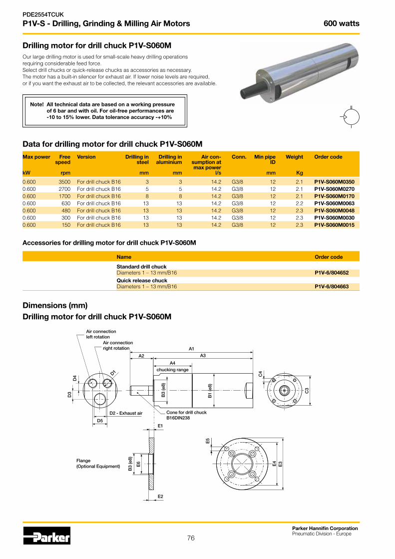
76
Parker Hannifin CorporationPneumatic Division - Europe
PDE2554TCUK
P1V-S - Drilling, Grinding & Milling Air Motors 600 watts
Note! All technical data are based on a working pressure of 6 bar and with oil. For oil-free performances are -10 to 15% lower. Data tolerance accuracy -+10%
Flange(Optional Equipment)
Air connectionleft rotation
Air connectionright rotation
Cone for drill chuckB16DIN238
D2 - Exhaust air
A4chucking range
A2
D1
C3
C4
E5
E4
E3
A1
A3
B1
(e8)
B3
(e8)
E1
E2
B3
(e8)
E6
D3
D4
D5
Drilling motor for drill chuck P1V-S060MDimensions (mm)
Drilling motor for drill chuck P1V-S060MOur large drilling motor is used for small-scale heavy drilling operations requiring considerable feed force.Select drill chucks or quick-release chucks as accessories as necessary.The motor has a built-in silencer for exhaust air. If lower noise levels are required, or if you want the exhaust air to be collected, the relevant accessories are available.
Data for drilling motor for drill chuck P1V-S060M
Max power Free Version Drilling in Drilling in Air con- Conn. Min pipe Weight Order code speed steel aluminium sumption at ID max power kW rpm mm mm l/s mm Kg
0.600 3500 For drill chuck B16 3 3 14.2 G3/8 12 2.1 P1V-S060M03500.600 2700 For drill chuck B16 5 5 14.2 G3/8 12 2.1 P1V-S060M02700.600 1700 For drill chuck B16 8 8 14.2 G3/8 12 2.1 P1V-S060M01700.600 630 For drill chuck B16 13 13 14.2 G3/8 12 2.2 P1V-S060M00630.600 480 For drill chuck B16 13 13 14.2 G3/8 12 2.3 P1V-S060M00480.600 300 For drill chuck B16 13 13 14.2 G3/8 12 2.3 P1V-S060M00300.600 150 For drill chuck B16 13 13 14.2 G3/8 12 2.3 P1V-S060M0015
Accessories for drilling motor for drill chuck P1V-S060M
Name Order code
Standard drill chuck Diameters 1 – 13 mm/B16 P1V-6/804652 Quick release chuck Diameters 1 – 13 mm/B16 P1V-6/804663
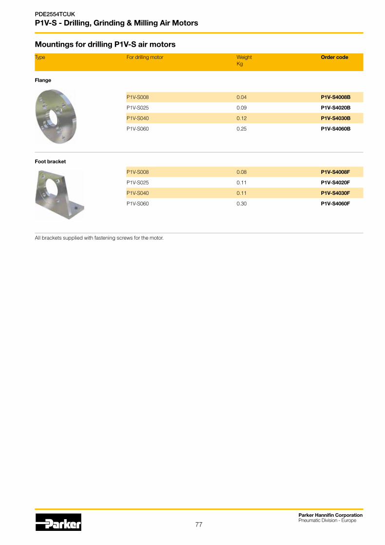
77
Parker Hannifin CorporationPneumatic Division - Europe
PDE2554TCUK
P1V-S - Drilling, Grinding & Milling Air Motors
Mountings for drilling P1V-S air motors
Type For drilling motor Weight Order code Kg
Flange
P1V-S008 0.04 P1V-S4008B
P1V-S025 0.09 P1V-S4020B
P1V-S040 0.12 P1V-S4030B
P1V-S060 0.25 P1V-S4060B
Foot bracket
P1V-S008 0.08 P1V-S4008F
P1V-S025 0.11 P1V-S4020F
P1V-S040 0.11 P1V-S4030F
P1V-S060 0.30 P1V-S4060F
All brackets supplied with fastening screws for the motor.
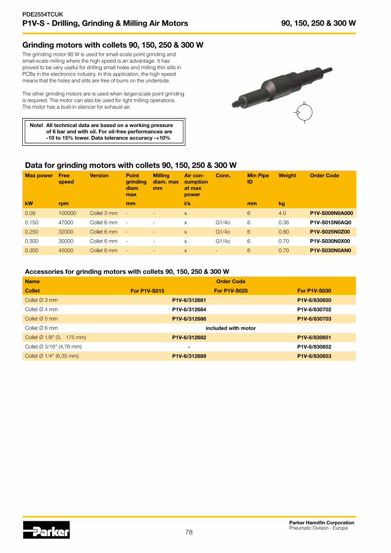
78
Parker Hannifin CorporationPneumatic Division - Europe
PDE2554TCUK
P1V-S - Drilling, Grinding & Milling Air Motors 90, 150, 250 & 300 W
Grinding motors with collets 90, 150, 250 & 300 WThe grinding motor 90 W is used for small-scale point grinding and small-scale milling where the high speed is an advantage. It has proved to be very useful for drilling small holes and milling thin slits in PCBs in the electronics industry. In this application, the high speed means that the holes and slits are free of burrs on the underside.
The other grinding motors are is used when larger-scale point grinding is required. The motor can also be used for light milling operations.The motor has a built-in silencer for exhaust air.
Note! All technical data are based on a working pressure of 6 bar and with oil. For oil-free performances are -10 to 15% lower. Data tolerance accuracy -+10%
Accessories for grinding motors with collets 90, 150, 250 & 300 WName Order Code
Collet For P1V-S015 For P1V-S025 For P1V-S030
Collet Ø 3 mm P1V-6/312681 P1V-6/830650
Collet Ø 4 mm P1V-6/312684 P1V-6/830702
Collet Ø 5 mm P1V-6/312686 P1V-6/830703
Collet Ø 6 mm included with motor
Collet Ø 1/8" (3, 175 mm) P1V-6/312682 P1V-6/830651
Collet Ø 3/16" (4,76 mm) - P1V-6/830652
Collet Ø 1/4" (6,35 mm) P1V-6/312689 P1V-6/830653
Data for grinding motors with collets 90, 150, 250 & 300 WMax power Free
speedVersion Point
grinding diam max
Milling diam. max mm
Air con-sumption at max power
Conn. Min Pipe ID
Weight Order Code
kW rpm mm l/s mm kg
0.09 100000 Collet 3 mm - - x 6 4.0 P1V-S009N0A000
0.150 47000 Collet 6 mm - - x G1/4o 6 0.36 P1V-S015N0AQ0
0.250 32000 Collet 6 mm - - x G1/4o 6 0.80 P1V-S025N0Z00
0.300 30000 Collet 6 mm - - x G1/4o 6 0.70 P1V-S030N0X00
0.300 45000 Collet 6 mm - - x - 6 0.70 P1V-S030N0AN0
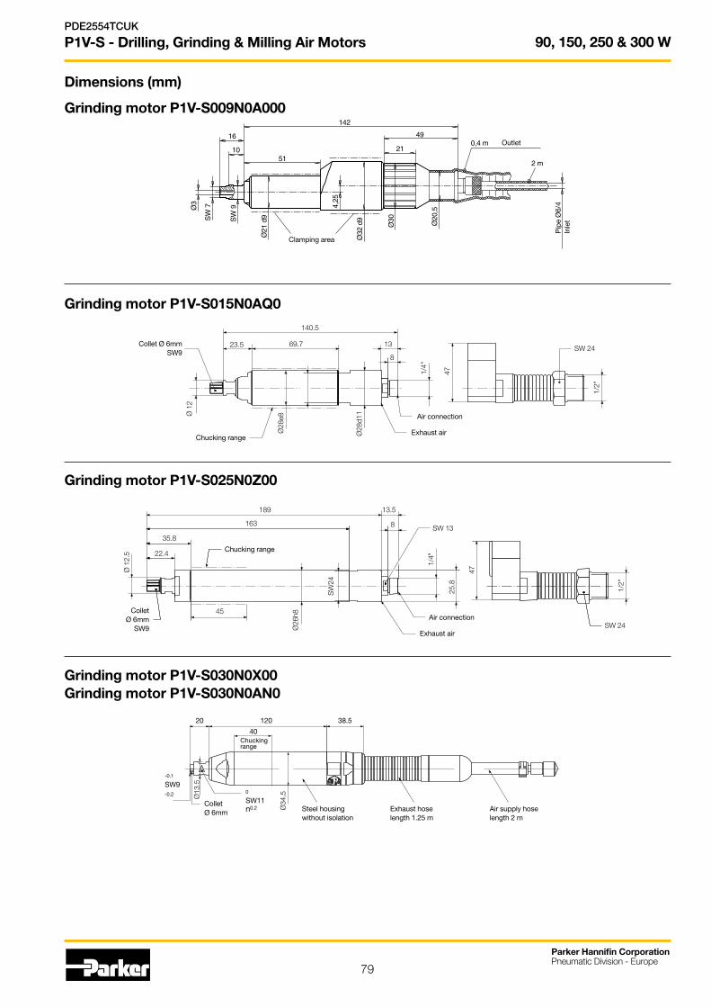
79
Parker Hannifin CorporationPneumatic Division - Europe
PDE2554TCUK
P1V-S - Drilling, Grinding & Milling Air Motors 90, 150, 250 & 300 W
Collet Ø 6mmSW9
Chucking range
Ø 1
2
Ø28
e8
Ø28
d11
1/4"
1/2"
Air connection
Exhaust air
Collet Ø 6mm
SW9
Chucking range
Ø 1
2.5
Ø26
h8
SW
24
1/4"
1/2"
Air connection
Exhaust air
Steel housingwithout isolation
Exhaust hoselength 1.25 m
Air supply hoselength 2 m
Ø34
.5Ø13
.5
Collet Ø 6mm
20 120 38.5
Chucking range
40
SW110
n0.2
SW9-0.1
-0.2
140.5
23.5 69.7 13
8SW 24
47
35.8
163
189 13.5
8
47
22.4
45
SW 24
25.8
SW 13
Grinding motor P1V-S015N0AQ0
Grinding motor P1V-S025N0Z00
Grinding motor P1V-S030N0X00Grinding motor P1V-S030N0AN0
142
16
10
Ø3
Ø21
d9
Ø32
d9
Ø30 Ø20
,5
21
490,4 m
2 m51
SW
7
SW
9 4,25
Pip
e Ø
6/4
Inle
t
Outlet
Clamping area
Grinding motor P1V-S009N0A000
Dimensions (mm)
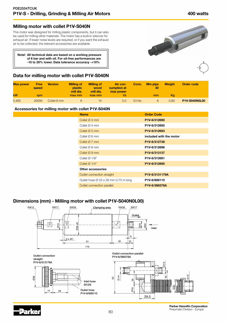
80
Parker Hannifin CorporationPneumatic Division - Europe
PDE2554TCUK
P1V-S - Drilling, Grinding & Milling Air Motors 400 watts
Note! All technical data are based on a working pressure of 6 bar and with oil. For oil-free performances are -10 to 20% lower. Data tolerance accuracy -+10%
Dimensions (mm) - Milling motor with collet P1V-S040N0L00)SW12 SW17 SW36 SW36 SW17
G1/
4
Ø20
8
103091
179
3 x 45°
Ø38
e8
Ø19
Ø38
15 28
G1/
2
G1/
4
62
26R
18
29,5
Ø25
G1/
430
Clamping area
Outlet
Inlet
SW12 SW17 SW36 SW36 SW17
G1/
4
Ø20
8
103091
179
3 x 45°
Ø38
e8
Ø19
Ø38
15 28
G1/
2
G1/
4
62
26R
18
29,5
Ø25
G1/
430
Outlet connection straightP1V-6/313179A
Inlet hoseØ12/6
Outlet hoseP1V-6/806110
SW12 SW17 SW36 SW36 SW17
G1/
4
Ø20
8
103091
179
3 x 45°
Ø38
e8
Ø19
Ø38
15 28
G1/
2
G1/
4
62
26R
18
29,5
Ø25
G1/
430
Outlet connection parallelP1V-6/388378A
Milling motor with collet P1V-S040NThis motor was designed for milling plastic components, but it can also be used for milling other materials. The motor has a built-in silencer for exhaust air. If lower noise levels are required, or if you want the exhaust air to be collected, the relevant accessories are available.
Data for milling motor with collet P1V-S040N
Max power Free Version Milling of Milling of Air con- Conn. Min pipe Weight Order code speed plastic wood sumption at ID mill dia. mill dia. max power kW rpm max mm max mm l/s mm Kg
0,400 20000 Collet 6 mm 8 10 5,0 G1/4o 6 0,80 P1V-S040N0L00
Accessories for milling motor with collet P1V-S040NName Order Code
Collet Ø 3 mm P1V-6/312690
Collet Ø 4 mm P1V-6/312692
Collet Ø 5 mm P1V-6/312693
Collet Ø 6 mm included with the motor
Collet Ø 7 mm P1V-6/312739
Collet Ø 8 mm P1V-6/312696
Collet Ø 9 mm P1V-6/313137
Collet Ø 1/8" P1V-6/312691
Collet Ø 1/4“ P1V-6/312695
Other accessories
Outlet connection straight P1V-6/3131179A
Outlet hose Ø 23 x 28 mm 0,75 m long P1V-6/806110
Outlet connection parallel P1V-6/388378A
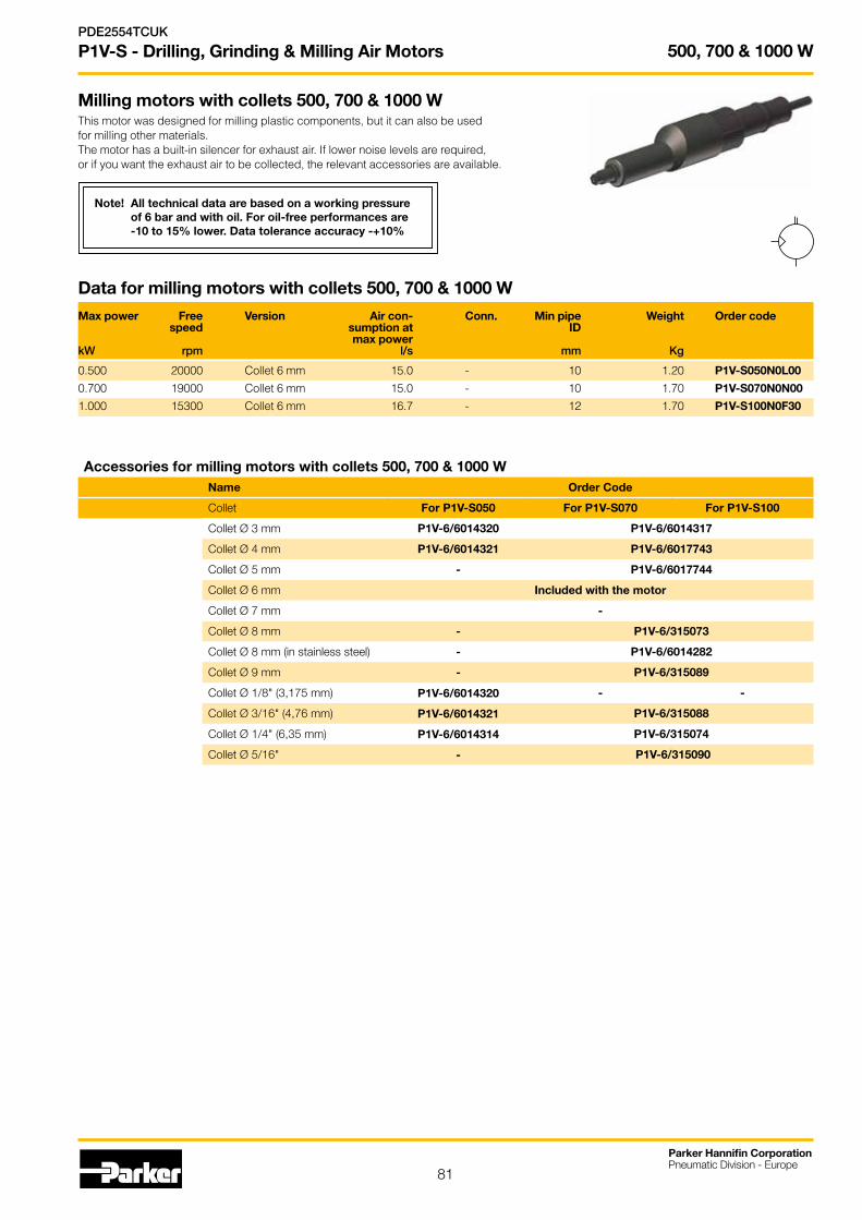
81
Parker Hannifin CorporationPneumatic Division - Europe
PDE2554TCUK
P1V-S - Drilling, Grinding & Milling Air Motors
Milling motors with collets 500, 700 & 1000 WThis motor was designed for milling plastic components, but it can also be used for milling other materials.The motor has a built-in silencer for exhaust air. If lower noise levels are required, or if you want the exhaust air to be collected, the relevant accessories are available.
500, 700 & 1000 W
Note! All technical data are based on a working pressure of 6 bar and with oil. For oil-free performances are -10 to 15% lower. Data tolerance accuracy -+10%
Data for milling motors with collets 500, 700 & 1000 W
Max power Free Version Air con- Conn. Min pipe Weight Order code speed sumption at ID max power kW rpm l/s mm Kg
0.500 20000 Collet 6 mm 15.0 - 10 1.20 P1V-S050N0L00
0.700 19000 Collet 6 mm 15.0 - 10 1.70 P1V-S070N0N00
1.000 15300 Collet 6 mm 16.7 - 12 1.70 P1V-S100N0F30
Accessories for milling motors with collets 500, 700 & 1000 WName Order Code
Collet For P1V-S050 For P1V-S070 For P1V-S100
Collet Ø 3 mm P1V-6/6014320 P1V-6/6014317
Collet Ø 4 mm P1V-6/6014321 P1V-6/6017743
Collet Ø 5 mm - P1V-6/6017744
Collet Ø 6 mm Included with the motor
Collet Ø 7 mm -
Collet Ø 8 mm - P1V-6/315073
Collet Ø 8 mm (in stainless steel) - P1V-6/6014282
Collet Ø 9 mm - P1V-6/315089
Collet Ø 1/8" (3,175 mm) P1V-6/6014320 - -
Collet Ø 3/16" (4,76 mm) P1V-6/6014321 P1V-6/315088
Collet Ø 1/4" (6,35 mm) P1V-6/6014314 P1V-6/315074
Collet Ø 5/16" - P1V-6/315090
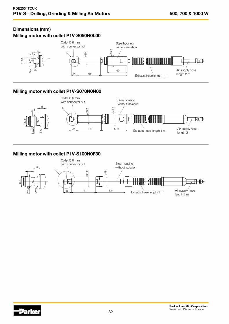
82
Parker Hannifin CorporationPneumatic Division - Europe
PDE2554TCUK
P1V-S - Drilling, Grinding & Milling Air Motors
X
ø39.
5
90
ø26
10329
6
SW
10
SW
14
ø14.
5
6
X
ø33.
2ø3
3.2
ø24
ø46.
5
37 111 117.58
9
SW
22
SW
17
ø49
36.7 111 134
ø24
89
SW
22
SW
17Milling motor with collet P1V-S050N0L00
Milling motor with collet P1V-S070N0N00
X
ø39.
5
90
ø26
10329
6
SW
10
SW
14
ø14.
5
6
X
ø33.
2ø3
3.2
ø24
ø46.
5
37 111 117.58
9
SW
22
SW
17
ø49
36.7 111 134
ø24
89
SW
22
SW
17
X
ø39.
5
90
ø26
10329
6S
W10
SW
14
ø14.
5
6
Xø3
3.2
ø33.
2
ø24
ø46.
5
37 111 117.58
9
SW
22
SW
17
ø49
36.7 111 134
ø24
89
SW
22
SW
17
X
ø39.
5
90
ø26
10329
6
SW
10
SW
14
ø14.
5
6
X
ø33.
2ø3
3.2
ø24
ø46.
537 111 117.5
89
SW
22
SW
17
ø49
36.7 111 134
ø24
89
SW
22
SW
17
Milling motor with collet P1V-S100N0F30
Collet Ø 6 mmwith connector nut
Steel housingwithout isolation
Exhaust hose length 1 m
Air supply hoselength 2 m
Collet Ø 6 mmwith connector nut Steel housing
without isolation
Exhaust hose length 1 mAir supply hoselength 2 m
Collet Ø 6 mmwith connector nut Steel housing
without isolation
Exhaust hose length 1 m Air supply hoselength 2 m
Dimensions (mm)
500, 700 & 1000 W
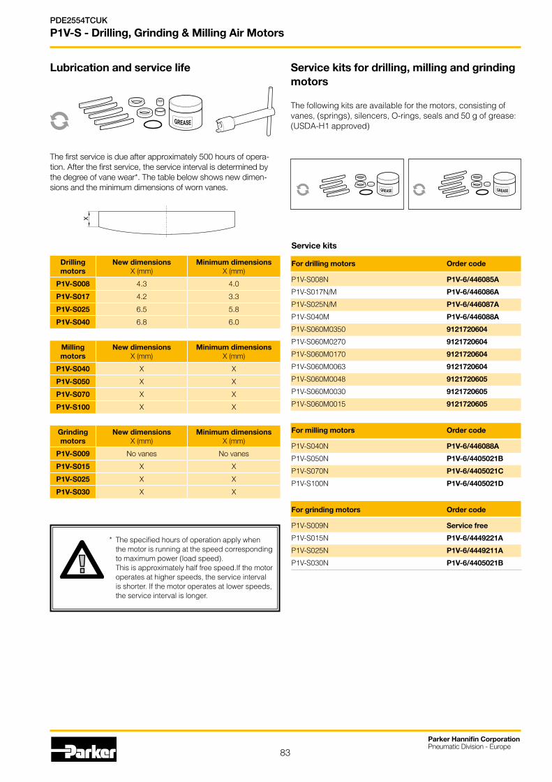
83
Parker Hannifin CorporationPneumatic Division - Europe
PDE2554TCUK
P1V-S - Drilling, Grinding & Milling Air Motors
X
The first service is due after approximately 500 hours of opera-tion. After the first service, the service interval is determined by the degree of vane wear*. The table below shows new dimen-sions and the minimum dimensions of worn vanes.
* The specified hours of operation apply when the motor is running at the speed corresponding to maximum power (load speed). This is approximately half free speed.If the motor operates at higher speeds, the service interval is shorter. If the motor operates at lower speeds, the service interval is longer.
Service kits for drilling, milling and grinding motors
The following kits are available for the motors, consisting of vanes, (springs), silencers, O-rings, seals and 50 g of grease: (USDA-H1 approved)
Service kits
For drilling motors Order code
P1V-S008N P1V-6/446085A
P1V-S017N/M P1V-6/446086A
P1V-S025N/M P1V-6/446087A
P1V-S040M P1V-6/446088A
P1V-S060M0350 9121720604
P1V-S060M0270 9121720604
P1V-S060M0170 9121720604
P1V-S060M0063 9121720604
P1V-S060M0048 9121720605
P1V-S060M0030 9121720605
P1V-S060M0015 9121720605
For milling motors Order code
P1V-S040N P1V-6/446088A
P1V-S050N P1V-6/4405021B
P1V-S070N P1V-6/4405021C
P1V-S100N P1V-6/4405021D
For grinding motors Order code
P1V-S009N Service free
P1V-S015N P1V-6/4449221A
P1V-S025N P1V-6/4449211A
P1V-S030N P1V-6/4405021B
Lubrication and service life
Drilling motors
New dimensionsX (mm)
Minimum dimensionsX (mm)
P1V-S008 4.3 4.0
P1V-S017 4.2 3.3
P1V-S025 6.5 5.8
P1V-S040 6.8 6.0
Milling motors
New dimensionsX (mm)
Minimum dimensionsX (mm)
P1V-S040 X X
P1V-S050 X X
P1V-S070 X X
P1V-S100 X X
Grinding motors
New dimensionsX (mm)
Minimum dimensionsX (mm)
P1V-S009 No vanes No vanes
P1V-S015 X X
P1V-S025 X X
P1V-S030 X X

Catalogue PDE2554TCUK - V5 - October 2015
Your local authorized Parker distributor
© 2015 Parker Hannifin Corporation. All rights reserved.
Parker Hannifin Ltd. Tachbrook Park Drive Tachbrook Park, Warwick CV34 6TUUnited Kingdom Tel.: +44 (0) 1926 317 878 Fax: +44 (0) 1926 317 [email protected]
Europe, Middle East, AfricaAE – United Arab Emirates, Dubai Tel: +971 4 8127100 [email protected]
AT – Austria, Wiener Neustadt Tel: +43 (0)2622 23501-0 [email protected]
AT – Eastern Europe, Wiener Neustadt Tel: +43 (0)2622 23501 900 [email protected]
AZ – Azerbaijan, Baku Tel: +994 50 2233 458 [email protected]
BE/LU – Belgium, Nivelles Tel: +32 (0)67 280 900 [email protected]
BG – Bulgaria, Sofia Tel: +359 2 980 1344 [email protected]
BY – Belarus, Minsk Tel: +48 (0)22 573 24 00 [email protected]
CH – Switzerland, Etoy Tel: +41 (0)21 821 87 00 [email protected]
CZ – Czech Republic, Klecany Tel: +420 284 083 111 [email protected]
DE – Germany, Kaarst Tel: +49 (0)2131 4016 0 [email protected]
DK – Denmark, Ballerup Tel: +45 43 56 04 00 [email protected]
ES – Spain, Madrid Tel: +34 902 330 001 [email protected]
FI – Finland, Vantaa Tel: +358 (0)20 753 2500 [email protected]
FR – France, Contamine s/Arve Tel: +33 (0)4 50 25 80 25 [email protected]
GR – Greece, Athens Tel: +30 210 933 6450 [email protected]
HU – Hungary, Budaörs Tel: +36 23 885 470 [email protected]
IE – Ireland, Dublin Tel: +353 (0)1 466 6370 [email protected]
IT – Italy, Corsico (MI) Tel: +39 02 45 19 21 [email protected]
KZ – Kazakhstan, Almaty Tel: +7 7273 561 000 [email protected]
NL – The Netherlands, Oldenzaal Tel: +31 (0)541 585 000 [email protected]
NO – Norway, Asker Tel: +47 66 75 34 00 [email protected]
PL – Poland, Warsaw Tel: +48 (0)22 573 24 00 [email protected]
PT – Portugal, Leca da Palmeira Tel: +351 22 999 7360 [email protected]
RO – Romania, Bucharest Tel: +40 21 252 1382 [email protected]
RU – Russia, Moscow Tel: +7 495 645-2156 [email protected]
SE – Sweden, Spånga Tel: +46 (0)8 59 79 50 00 [email protected]
SK – Slovakia, Banská Bystrica Tel: +421 484 162 252 [email protected]
SL – Slovenia, Novo Mesto Tel: +386 7 337 6650 [email protected]
TR – Turkey, Istanbul Tel: +90 216 4997081 [email protected]
UA – Ukraine, Kiev Tel: +48 (0)22 573 24 00 [email protected]
UK – United Kingdom, Warwick Tel: +44 (0)1926 317 878 [email protected]
ZA – South Africa, Kempton Park Tel: +27 (0)11 961 0700 [email protected]
North AmericaCA – Canada, Milton, Ontario Tel: +1 905 693 3000
US – USA, Cleveland Tel: +1 216 896 3000
Asia PacificAU – Australia, Castle Hill Tel: +61 (0)2-9634 7777
CN – China, Shanghai Tel: +86 21 2899 5000
HK – Hong Kong Tel: +852 2428 8008
IN – India, Mumbai Tel: +91 22 6513 7081-85
JP – Japan, Tokyo Tel: +81 (0)3 6408 3901
KR – South Korea, Seoul Tel: +82 2 559 0400
MY – Malaysia, Shah Alam Tel: +60 3 7849 0800
NZ – New Zealand, Mt Wellington Tel: +64 9 574 1744
SG – Singapore Tel: +65 6887 6300
TH – Thailand, Bangkok Tel: +662 186 7000
TW – Taiwan, Taipei Tel: +886 2 2298 8987
South AmericaAR – Argentina, Buenos Aires Tel: +54 3327 44 4129
BR – Brazil, Sao Jose dos Campos Tel: +55 800 727 5374
CL – Chile, Santiago Tel: +56 2 623 1216
MX – Mexico, Toluca Tel: +52 72 2275 4200
Parker Worldwide
European Product Information Centre
Free phone: 00 800 27 27 5374
(from AT, BE, CH, CZ, DE, DK, EE, ES, FI,
FR, IE, IL, IS, IT, LU, MT, NL, NO, PL, PT, RU,
SE, SK, UK, ZA)