Embed Size (px)
Citation preview

PRODUCTINSTRUCTIONS
ONEPOINTE SOLUTIONS
H O W T O G U I D E S T O S U C E S S F U L L Y A N D E F F I C I E N T L YI N S T A L L O U R P R O D U C T S
METAL LABORATORY CASEWORK
presents
AIR MASTER SYSTEMS INSTALLATION GUIDE TABLE OF CONTENTS
GENERAL INFORMATION ......................................................................................................1
Freight Damage ....................................................................................................................... 1
Repairing Paint Scratches ........................................................................................................ 1
BASE CABINETS ...................................................................................................................... 2
Drawer Removal and Reinstallation ........................................................................................2
Replacing Drawer Fronts ......................................................................................................... 3
Door Adjustment ..................................................................................................................... 4
Shelf Installation and Adjustment ............................................................................................4
Removing and Installing Back Access Panels / Bottom Panels ................................................5
Leveling .................................................................................................................................. 5
Installing Pull-Out Shelves ......................................................................................................6
Sink Base Cabinets and Sink Support Assemblies ...................................................................8
Installing Knee Space Panels ...................................................................................................9
Base Cabinet Fillers .............................................................................................................. 10
Installing L-Front Fillers.................................................................................................... 10 Installing L-Fillers ............................................................................................................. 11 Installing C-Front Fillers ................................................................................................... 12 Installing C-Fillers ............................................................................................................. 13 Installing Inside Corner Fillers .......................................................................................... 14
ACID STORAGE CABINETS – VENTING ............................................................................. 15 WALL CASES ......................................................................................................................... 16
Wall Case Installation ........................................................................................................... 16
Installing Wall Case Sloping Tops......................................................................................... 17
Removing Wall Case Sliding Doors ...................................................................................... 18
Wall Case Fillers ................................................................................................................... 19
Installing Wall Case Front Fillers ...................................................................................... 19 Installing Wall Case Inside Corner Fillers .......................................................................... 20
FLOOR CASES ........................................................................................................................ 21
Floor Case Installation........................................................................................................... 21
Removing Floor Case Sliding Doors ..................................................................................... 21
Installing Floor Case Front L-Fillers...................................................................................... 22
APRONS AND UTILITY TABLES ......................................................................................... 23
Apron Installation ................................................................................................................. 23
Utility Table Installation........................................................................................................ 24

APPENDIX – FILLER SPECIFICATIONS .............................................................................. 25
Base Cabinet L-Front Fillers ................................................................................................. 25
Base Cabinet L-Fillers ........................................................................................................... 26
Base Cabinet C-Front Fillers ................................................................................................. 27
Base Cabinet C-Fillers........................................................................................................... 28
Base Cabinet Inside Corner Fillers ........................................................................................ 29
Wall Case Front Fillers.......................................................................................................... 30
Wall Case Inside Corner Fillers ............................................................................................. 31
Floor Case L-Front Fillers ..................................................................................................... 32

1
GENERAL INFORMATION Freight Damage
It is the buyer’s responsibility to inspect goods thoroughly for apparent damage before accepting shipment. Please do not refuse shipment. Rather, if there is any apparent damage to the unit or packaging, please clearly note that damage (in specific detail) on the bill of lading when accepting delivery. Failure to note apparent damage on the bill of lading or another shipment document may prevent the purchaser and Air Master Systems from successfully pursuing a freight-damage claim. Please contact Air Master Systems immediately in the event of apparent shipping damage, or in the event of damagediscovered upon un-packing the product (i.e., concealed damage). Carriers often impose rigid timelines for makinga freight damage claim. Accordingly, failure to inspect the package upon receipt and/or failure to contact Air MasterSystems immediately upon learning of freight damage may prevent the purchaser and Air Master Systems fromsuccessfully pursuing a freight-damage claim.
Repairing Paint Scratches
Steps: A. Clean the surface will take care of many scratches and scuffs. Casework surfaces are coated with a durable
powder coat paint. If non-abrasive cleaners fail to clean the surface, a cleaner with mild abrasives may be used. Use caution, however, as abrasive cleaners can change the sheen of the paint finish and may make the finish become glossy.
B. If the above is not effective, you may want to try touch-up paint. We have matches available for all of our standard colors.
C. As a last resort, replace the damaged part.
2
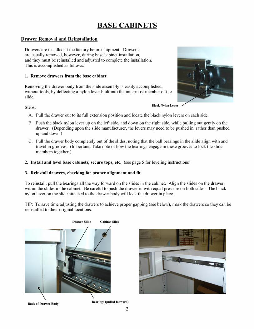
BASE CABINETS Drawer Removal and Reinstallation
Drawers are installed at the factory before shipment. Drawers are usually removed, however, during base cabinet installation, and they must be reinstalled and adjusted to complete the installation. This is accomplished as follows: 1. Remove drawers from the base cabinet. Removing the drawer body from the slide assembly is easily accomplished, without tools, by deflecting a nylon lever built into the innermost member of the slide. Steps:
A. Pull the drawer out to its full extension position and locate the black nylon levers on each side.
B. Push the black nylon lever up on the left side, and down on the right side, while pulling out gently on the drawer. (Depending upon the slide manufacturer, the levers may need to be pushed in, rather than pushed up and down.)
C. Pull the drawer body completely out of the slides, noting that the ball bearings in the slide align with and travel in grooves. (Important: Take note of how the bearings engage in these grooves to lock the slide members together.)
2. Install and level base cabinets, secure tops, etc. (see page 5 for leveling instructions) 3. Reinstall drawers, checking for proper alignment and fit. To reinstall, pull the bearings all the way forward on the slides in the cabinet. Align the slides on the drawer within the slides in the cabinet. Be careful to push the drawer in with equal pressure on both sides. The black nylon lever on the slide attached to the drawer body will lock the drawer in place. TIP: To save time adjusting the drawers to achieve proper gapping (see below), mark the drawers so they can be reinstalled to their original locations.
Black Nylon Lever
Drawer Slide Cabinet Slide
Bearings (pulled forward) Back of Drawer Body

3
4. If necessary, adjust drawers up or down. You can adjust the drawer up or down if the gap at the top or bottom is uneven. For cabinets with recessed fronts, the proper spacing around a drawer front is 0.125” (1/8”) on all sides. For cabinets with overlay fronts, the proper horizontal spacing between two drawer fronts, or between a door and drawer front, is also 0.125”. For 35” high base cabinets, the top gap/reveal is 0.575”, as shown below. The bottom gap/reveal is 0.65” for both 29” and 35” high base cabinets. Steps to adjust drawers up or down:
A. Loosen the screws at the bottom of the drawer front.
B. Grab the drawer front and slide it up or down.
C. Tighten the screws and check for fit. Repeat if necessary.
Gapping for Base Cabinet with Standard (Inset) Fronts Gapping for Base Cabinet with Overlay Fronts
Replacing Drawer Fronts
As noted above, in certain instances it may be necessary to replaced a damaged drawer front. This is easily accomplished by the following steps:
A. Using a thin blade tool, pry out the nylon glides on the side of the drawer front. (Note: This step is not applicable for casework with overlay-style drawer fronts, as those fronts do not have nylon glides.)
B. Use a Philips head screwdriver to remove the two screws at the bottom of the drawer front. C. Pull the drawer front slightly outward and up to remove it from the drawer body. D. Place the new drawer front on the drawer body. E. Tighten the two screws at the bottom of the drawer front. F. Push in the two nylon glides (inset-style drawer fronts only).
Loosen Screw to Adjust
4
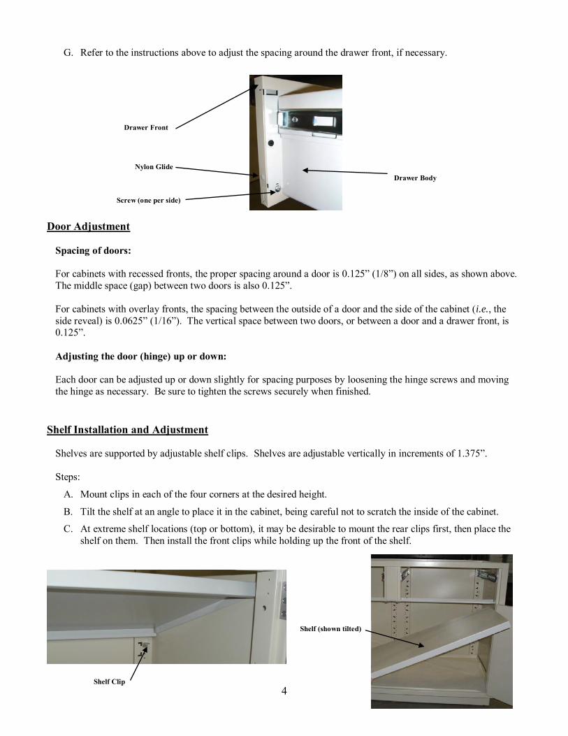
G. Refer to the instructions above to adjust the spacing around the drawer front, if necessary.
Door Adjustment
Spacing of doors: For cabinets with recessed fronts, the proper spacing around a door is 0.125” (1/8”) on all sides, as shown above. The middle space (gap) between two doors is also 0.125”. For cabinets with overlay fronts, the spacing between the outside of a door and the side of the cabinet (i.e., the side reveal) is 0.0625” (1/16”). The vertical space between two doors, or between a door and a drawer front, is 0.125”. Adjusting the door (hinge) up or down: Each door can be adjusted up or down slightly for spacing purposes by loosening the hinge screws and moving the hinge as necessary. Be sure to tighten the screws securely when finished.
Shelf Installation and Adjustment
Shelves are supported by adjustable shelf clips. Shelves are adjustable vertically in increments of 1.375”. Steps:
A. Mount clips in each of the four corners at the desired height.
B. Tilt the shelf at an angle to place it in the cabinet, being careful not to scratch the inside of the cabinet.
C. At extreme shelf locations (top or bottom), it may be desirable to mount the rear clips first, then place the shelf on them. Then install the front clips while holding up the front of the shelf.
Shelf Clip
Shelf (shown tilted)
Drawer Front
Nylon Glide Drawer Body
Screw (one per side)
5
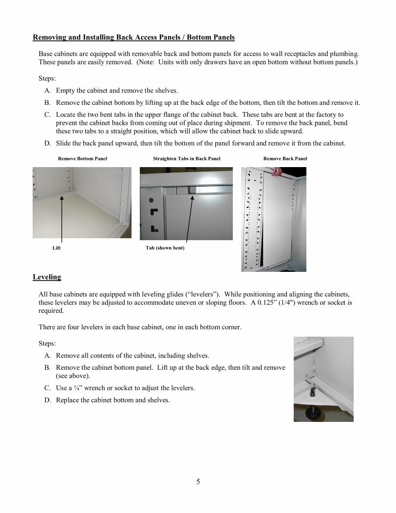
Removing and Installing Back Access Panels / Bottom Panels
Base cabinets are equipped with removable back and bottom panels for access to wall receptacles and plumbing. These panels are easily removed. (Note: Units with only drawers have an open bottom without bottom panels.) Steps:
A. Empty the cabinet and remove the shelves.
B. Remove the cabinet bottom by lifting up at the back edge of the bottom, then tilt the bottom and remove it.
C. Locate the two bent tabs in the upper flange of the cabinet back. These tabs are bent at the factory to prevent the cabinet backs from coming out of place during shipment. To remove the back panel, bend these two tabs to a straight position, which will allow the cabinet back to slide upward.
D. Slide the back panel upward, then tilt the bottom of the panel forward and remove it from the cabinet.
Remove Bottom Panel
Straighten Tabs in Back Panel Remove Back Panel
Leveling
All base cabinets are equipped with leveling glides (“levelers”). While positioning and aligning the cabinets, these levelers may be adjusted to accommodate uneven or sloping floors. A 0.125” (1/4") wrench or socket is required. There are four levelers in each base cabinet, one in each bottom corner. Steps:
A. Remove all contents of the cabinet, including shelves.
B. Remove the cabinet bottom panel. Lift up at the back edge, then tilt and remove (see above).
C. Use a ¼” wrench or socket to adjust the levelers.
D. Replace the cabinet bottom and shelves.
Lift Tab (shown bent)
6
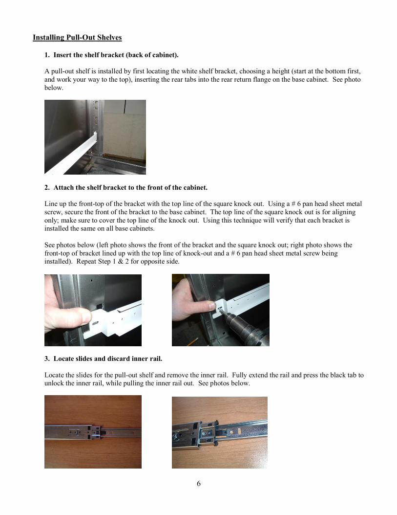
Installing Pull-Out Shelves
1. Insert the shelf bracket (back of cabinet). A pull-out shelf is installed by first locating the white shelf bracket, choosing a height (start at the bottom first, and work your way to the top), inserting the rear tabs into the rear return flange on the base cabinet. See photo below.
2. Attach the shelf bracket to the front of the cabinet. Line up the front-top of the bracket with the top line of the square knock out. Using a # 6 pan head sheet metal screw, secure the front of the bracket to the base cabinet. The top line of the square knock out is for aligning only; make sure to cover the top line of the knock out. Using this technique will verify that each bracket is installed the same on all base cabinets. See photos below (left photo shows the front of the bracket and the square knock out; right photo shows the front-top of bracket lined up with the top line of knock-out and a # 6 pan head sheet metal screw being installed). Repeat Step 1 & 2 for opposite side.
3. Locate slides and discard inner rail. Locate the slides for the pull-out shelf and remove the inner rail. Fully extend the rail and press the black tab to unlock the inner rail, while pulling the inner rail out. See photos below.

7
Discard the inner rail – this is not needed.
4. Install slide into the shelf bracket. Install pull-out shelf slide to previously installed bracket by placing the slide into the bracket, using two #6 pan head sheet metal screws. Install one screw into the front hole of the slide and the bracket (as shown below); the holes in the slide and the brackets line up. Use the front hole on the front of the bracket and slide, and the front hole in the back of the bracket and slide. Repeat this step for opposite side.
5. Install pull-out shelf. Locate the pull-out shelf and line up the factory installed rail to the slides that were installed in step 4. See photos below. Open and close the pull out shelf a few times to set the slides.
8
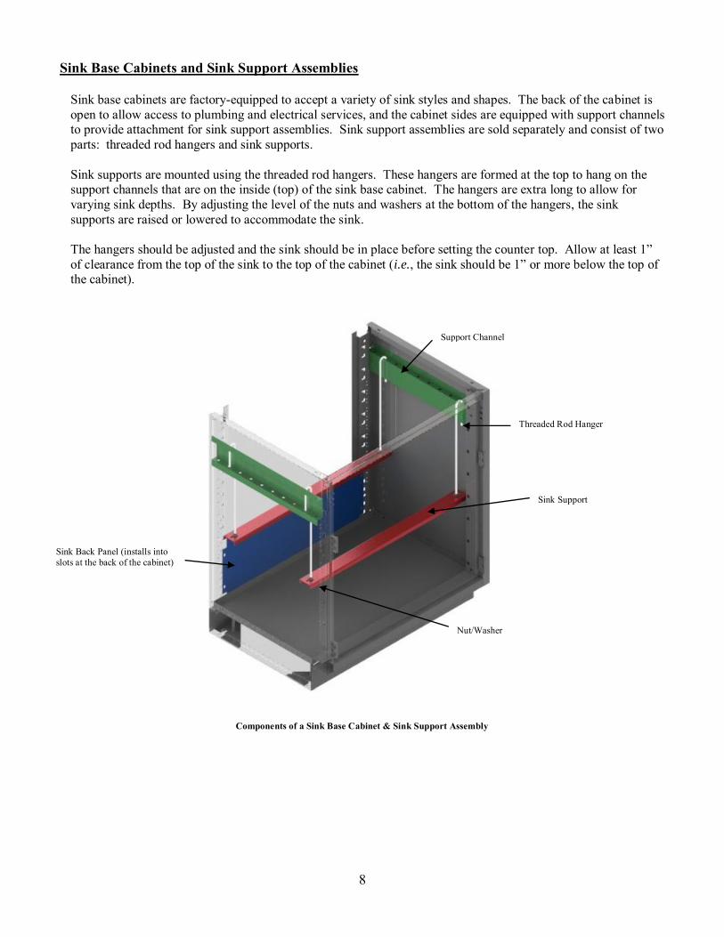
Sink Base Cabinets and Sink Support Assemblies
Sink base cabinets are factory-equipped to accept a variety of sink styles and shapes. The back of the cabinet is open to allow access to plumbing and electrical services, and the cabinet sides are equipped with support channels to provide attachment for sink support assemblies. Sink support assemblies are sold separately and consist of two parts: threaded rod hangers and sink supports. Sink supports are mounted using the threaded rod hangers. These hangers are formed at the top to hang on the support channels that are on the inside (top) of the sink base cabinet. The hangers are extra long to allow for varying sink depths. By adjusting the level of the nuts and washers at the bottom of the hangers, the sink supports are raised or lowered to accommodate the sink. The hangers should be adjusted and the sink should be in place before setting the counter top. Allow at least 1” of clearance from the top of the sink to the top of the cabinet (i.e., the sink should be 1” or more below the top of the cabinet).
Components of a Sink Base Cabinet & Sink Support Assembly
Sink Back Panel (installs into slots at the back of the cabinet)
Threaded Rod Hanger
Support Channel
Nut/Washer
Sink Support

9
Installing Knee Space Panels
Knee space panels are installed using standard filler clips. Steps:
A. Using # 8 sheet metal screws, install three filler clips vertically on each side of the knee space panel. The filler clips will attach to the adjoining casework at the desired location.
B. Slide the knee space panel into the filler clips. Knee space panels slide into place with a friction fit. No additional fasteners are required.
Step A: Attach filler clips along each side of the knee space panel. Step B: Slide the knee space panel into the filler clips.
Installed knee space panel
Left Cabinet Hidden to Show Filler Clips
10
Base Cabinet Fillers
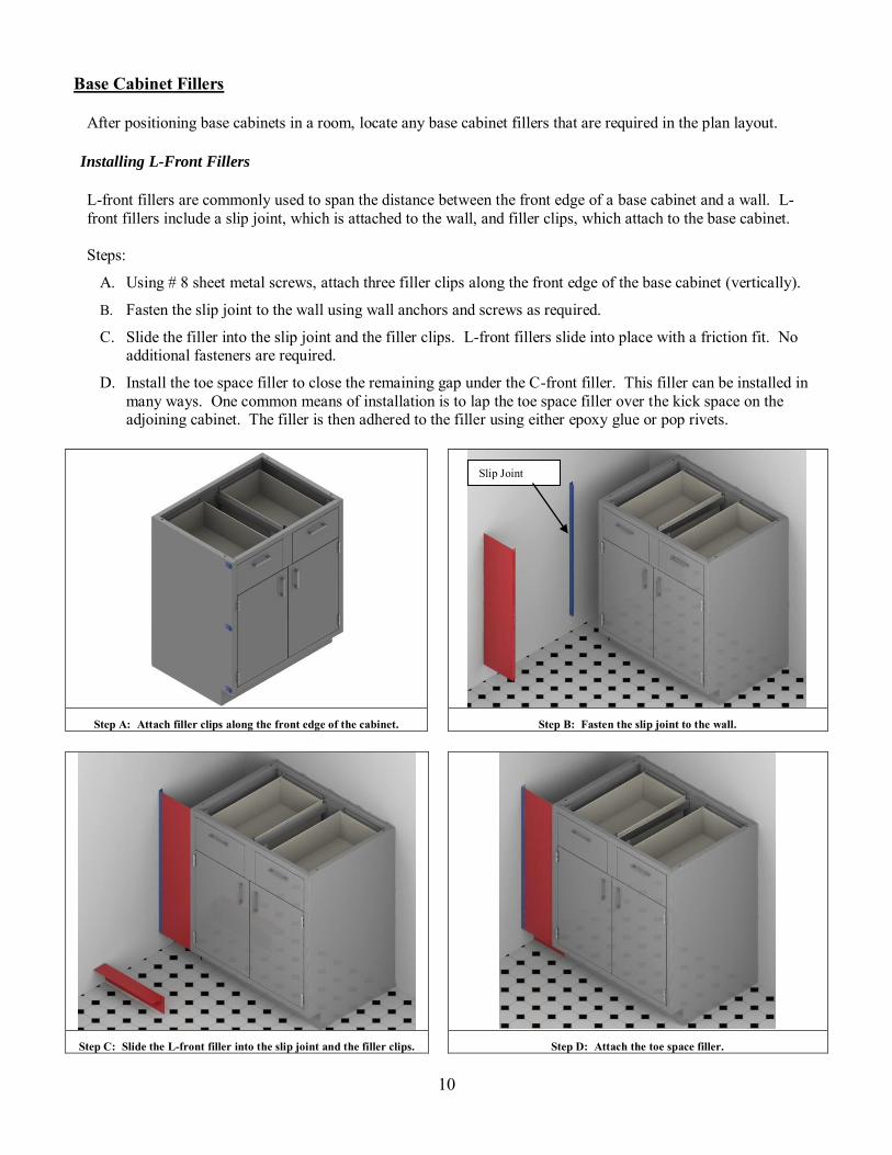
After positioning base cabinets in a room, locate any base cabinet fillers that are required in the plan layout. Installing L-Front Fillers
L-front fillers are commonly used to span the distance between the front edge of a base cabinet and a wall. L-front fillers include a slip joint, which is attached to the wall, and filler clips, which attach to the base cabinet. Steps:
A. Using # 8 sheet metal screws, attach three filler clips along the front edge of the base cabinet (vertically).
B. Fasten the slip joint to the wall using wall anchors and screws as required.
C. Slide the filler into the slip joint and the filler clips. L-front fillers slide into place with a friction fit. No additional fasteners are required.
D. Install the toe space filler to close the remaining gap under the C-front filler. This filler can be installed in many ways. One common means of installation is to lap the toe space filler over the kick space on the adjoining cabinet. The filler is then adhered to the filler using either epoxy glue or pop rivets.
Step A: Attach filler clips along the front edge of the cabinet. Step B: Fasten the slip joint to the wall.
Step C: Slide the L-front filler into the slip joint and the filler clips. Step D: Attach the toe space filler.
Slip Joint
11
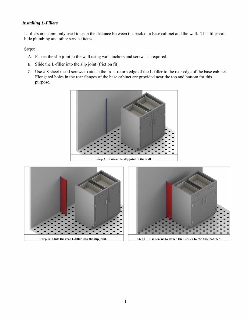
Installing L-Fillers
L-fillers are commonly used to span the distance between the back of a base cabinet and the wall. This filler can hide plumbing and other service items. Steps:
A. Fasten the slip joint to the wall using wall anchors and screws as required.
B. Slide the L-filler into the slip joint (friction fit).
C. Use # 8 sheet metal screws to attach the front return edge of the L-filler to the rear edge of the base cabinet. Elongated holes in the rear flanges of the base cabinet are provided near the top and bottom for this purpose.
Step A: Fasten the slip joint to the wall.
Step B: Slide the rear L-filler into the slip joint. Step C: Use screws to attach the L-filler to the base cabinet.

12
Installing C-Front Fillers
C-front fillers are commonly used where two base cabinets come together in a corner. Steps:
A. Using #8 sheet metal screws, attach three filler clips along the front edge of each base cabinet (vertically).
B. Slide the C-front filler into the filler clips, as shown below. C-front fillers slide into place with a friction fit only. No additional fasteners are required.
C. Install the toe space filler to close the remaining gap under the C-front filler. This filler can be installed in many ways. One common means of installation is to lap the toe space filler over the kick space on the adjoining cabinet. The filler is then adhered to the filler using either epoxy glue or pop rivets.
Step A: Attach filler clips along the front edge of each cabinet. Step B: Slide the C-front filler into the filler clips.
Step C: Attach the toe space filler.
13
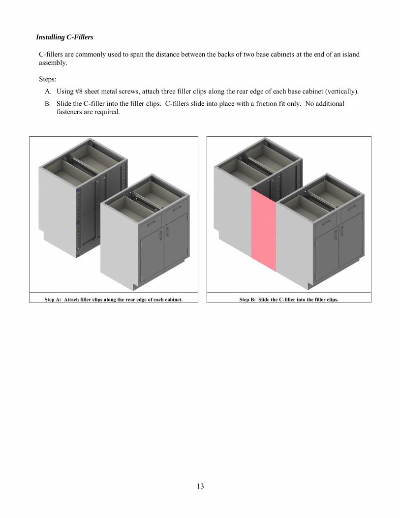
Installing C-Fillers
C-fillers are commonly used to span the distance between the backs of two base cabinets at the end of an island assembly. Steps:
A. Using #8 sheet metal screws, attach three filler clips along the rear edge of each base cabinet (vertically).
B. Slide the C-filler into the filler clips. C-fillers slide into place with a friction fit only. No additional fasteners are required.
Step A: Attach filler clips along the rear edge of each cabinet. Step B: Slide the C-filler into the filler clips.
14
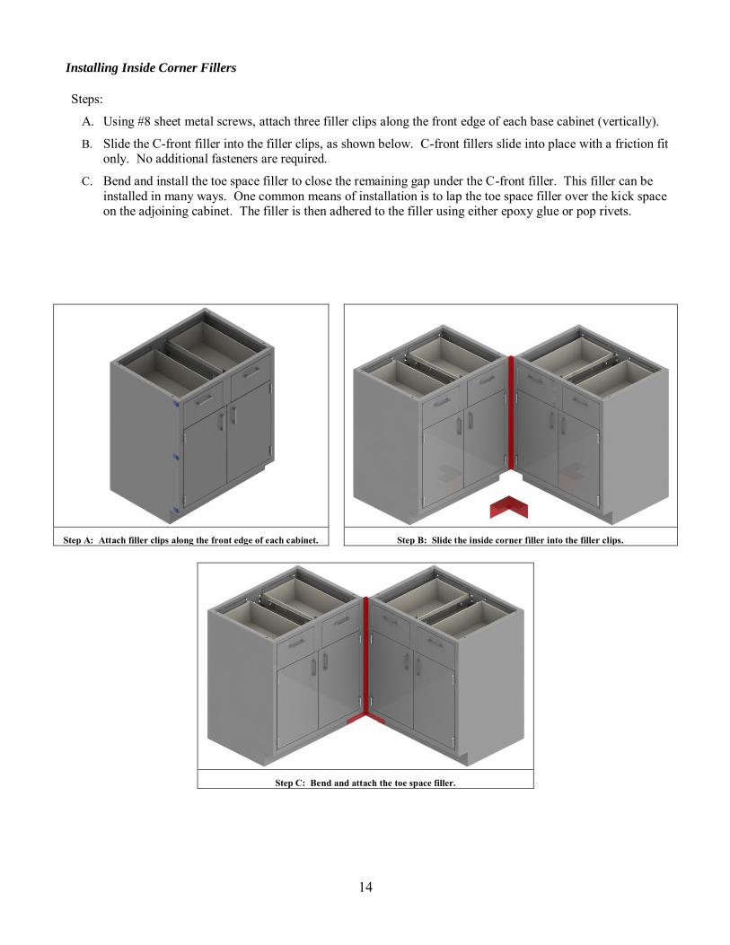
Installing Inside Corner Fillers
Steps:
A. Using #8 sheet metal screws, attach three filler clips along the front edge of each base cabinet (vertically).
B. Slide the C-front filler into the filler clips, as shown below. C-front fillers slide into place with a friction fit only. No additional fasteners are required.
C. Bend and install the toe space filler to close the remaining gap under the C-front filler. This filler can be installed in many ways. One common means of installation is to lap the toe space filler over the kick space on the adjoining cabinet. The filler is then adhered to the filler using either epoxy glue or pop rivets.
Step A: Attach filler clips along the front edge of each cabinet. Step B: Slide the inside corner filler into the filler clips.
Step C: Bend and attach the toe space filler.

15
ACID STORAGE CABINETS – VENTING The back of acid storage cabinets feature two venting holes that are plugged with 2” hole plugs. In order to function properly, acid storage cabinets must be vented to alleviate any corrosive fumes that may otherwise accumulate inside the cabinet. It is the installer’s responsibility to ensure that venting is proper and adequate for the intended use. Failure to vent a cabinet properly may cause corrosion of the cabinet and the cabinet hardware, depending upon the types of chemicals stored in the cabinet. PVC vent kits (sold separately) are designed to assist in the venting of acid storage cabinets. A vent kit fits through the through the 2” hole in the back of the acid storage cabinet, as shown below. Acid storage cabinets feature a removable back panel that also can be used for venting.
Back of an acid cabinet Venting hole and hole plug Optional vent kit
Installing vent kit through cabinet back Securing vent kit from inside the cabinet Removable back panel
16
WALL CASES
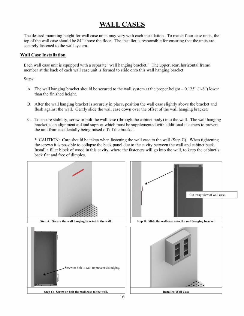
The desired mounting height for wall case units may vary with each installation. To match floor case units, the top of the wall case should be 84” above the floor. The installer is responsible for ensuring that the units are securely fastened to the wall system.
Wall Case Installation Each wall case unit is equipped with a separate “wall hanging bracket.” The upper, rear, horizontal frame member at the back of each wall case unit is formed to slide onto this wall hanging bracket.
Steps:
A. The wall hanging bracket should be secured to the wall system at the proper height – 0.125” (1/8”) lower
than the finished height.
B. After the wall hanging bracket is securely in place, position the wall case slightly above the bracket and flush against the wall. Gently slide the wall case down over the offset of the wall hanging bracket.
C. To ensure stability, screw or bolt the wall case (through the cabinet body) into the wall. The wall hanging
bracket is an alignment aid and support which must be supplemented with additional fasteners to prevent the unit from accidentally being raised off of the bracket.
* CAUTION: Care should be taken when fastening the wall case to the wall (Step C). When tightening the screws it is possible to collapse the back panel due to the cavity between the wall and cabinet back. Install a filler block of wood in this cavity, where the fasteners will go into the wall, to keep the cabinet’s back flat and free of dimples.
Step A: Secure the wall hanging bracket to the wall. Step B: Slide the wall case onto the wall hanging bracket.
Step C: Screw or bolt the wall case to the wall. Installed Wall Case
Cut away view of wall case
Screw or bolt to wall to prevent dislodging.
17
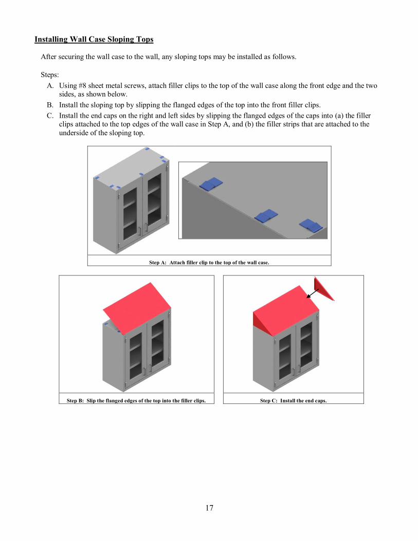
Installing Wall Case Sloping Tops
After securing the wall case to the wall, any sloping tops may be installed as follows. Steps:
A. Using #8 sheet metal screws, attach filler clips to the top of the wall case along the front edge and the two sides, as shown below.
B. Install the sloping top by slipping the flanged edges of the top into the front filler clips. C. Install the end caps on the right and left sides by slipping the flanged edges of the caps into (a) the filler
clips attached to the top edges of the wall case in Step A, and (b) the filler strips that are attached to the underside of the sloping top.
Step A: Attach filler clip to the top of the wall case.
Step B: Slip the flanged edges of the top into the filler clips. Step C: Install the end caps.

18
Removing Wall Case Sliding Doors
Glass and metal wall case sliding doors can be easily removed. .
Steps: A. Slide the outermost door to the center of the wall case. B. Grasp the sides of the door and lift upward. C. Swing out the bottom edge of the door. D. When the bottom edge of the outer door clears the front of the wall case, lower and remove the door. E. Reach into the wall case and stack/lean the shelves against the back of the wall case, as shown below. It is
not necessary to remove the shelves. F. Repeat Steps A through D for the inner door, except the bottom edge of the inner door will swing into the
cabinet. G. When the bottom edge of the inner door clears the front of the wall case, lower and remove the door.
Removing the outer door – lift the door up and swing out the bottom edge
Removing the inner door (note: lean shelves against back of case to create room for swinging the door into the cabinet)

19
Wall Case Fillers
After positioning wall cases in a room, locate any wall case fillers that are required in the plan layout. Installing Wall Case Front Fillers
Wall case front fillers are commonly used where a filler is needed between the front of a wall case and a wall.
Steps:
A. Using # 8 sheet metal screws, attach filler clips along the front edge of the wall case (vertically), as shown below. Install two filler clips for 24” and 30” high wall cases; install three clips for 36” and 48” high units. Also, attach one filler clip each along the top and bottom edges of the wall case.
B. Slide all three sides of the wall case front filler into the filler clips, as shown below. The filler is flexible, and the top and bottom can be moved up or down slightly if necessary to fit into the clips. Front fillers slide into place with a friction fit only. No additional fasteners are required.
Step A: Attach filler clip along the front, top and bottom edges.
Step B: Slide the wall case front filler into the filler clips.
20
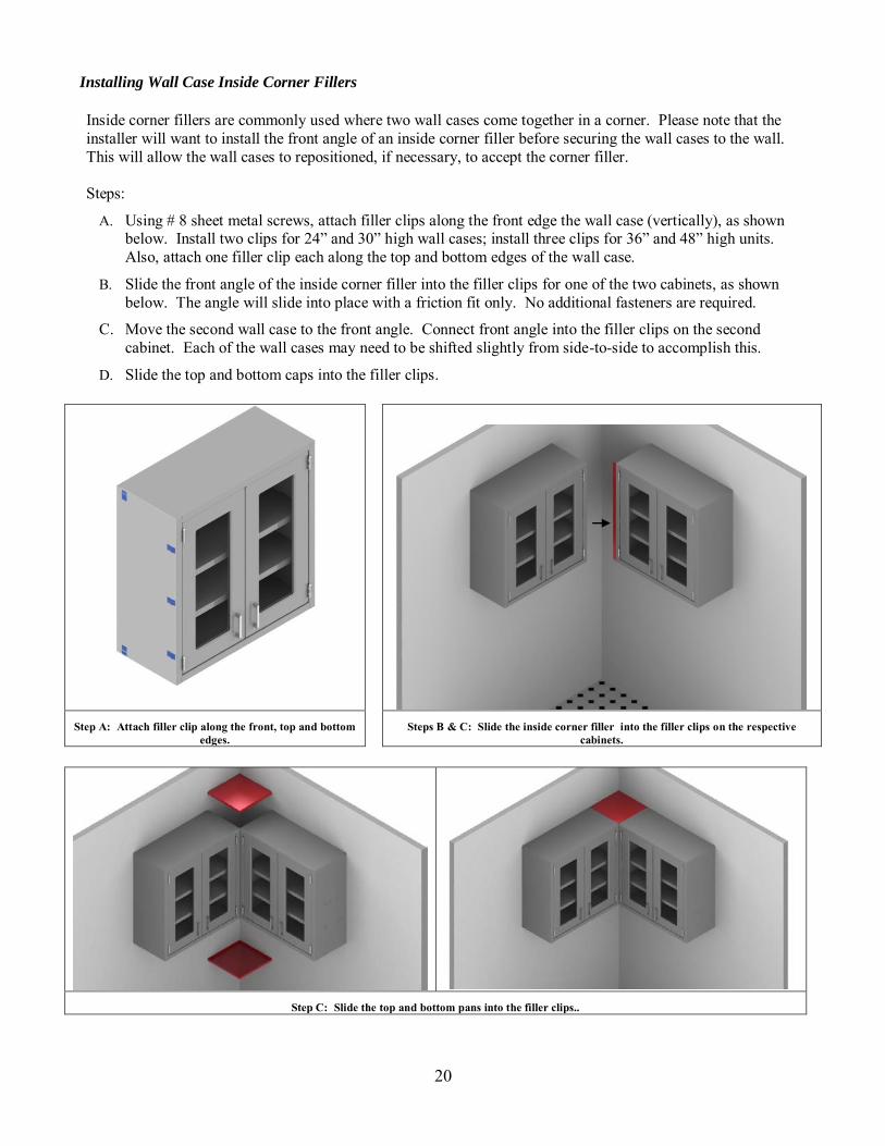
Installing Wall Case Inside Corner Fillers
Inside corner fillers are commonly used where two wall cases come together in a corner. Please note that the installer will want to install the front angle of an inside corner filler before securing the wall cases to the wall. This will allow the wall cases to repositioned, if necessary, to accept the corner filler. Steps:
A. Using # 8 sheet metal screws, attach filler clips along the front edge the wall case (vertically), as shown below. Install two clips for 24” and 30” high wall cases; install three clips for 36” and 48” high units. Also, attach one filler clip each along the top and bottom edges of the wall case.
B. Slide the front angle of the inside corner filler into the filler clips for one of the two cabinets, as shown below. The angle will slide into place with a friction fit only. No additional fasteners are required.
C. Move the second wall case to the front angle. Connect front angle into the filler clips on the second cabinet. Each of the wall cases may need to be shifted slightly from side-to-side to accomplish this.
D. Slide the top and bottom caps into the filler clips.
Step A: Attach filler clip along the front, top and bottom
edges. Steps B & C: Slide the inside corner filler into the filler clips on the respective
cabinets.
Step C: Slide the top and bottom pans into the filler clips..
21
FLOOR CASES
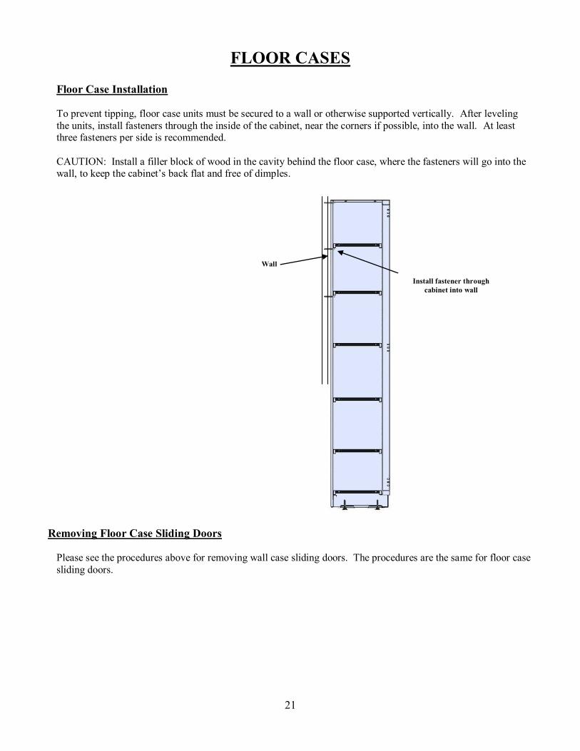
Floor Case Installation
To prevent tipping, floor case units must be secured to a wall or otherwise supported vertically. After leveling the units, install fasteners through the inside of the cabinet, near the corners if possible, into the wall. At least three fasteners per side is recommended. CAUTION: Install a filler block of wood in the cavity behind the floor case, where the fasteners will go into the wall, to keep the cabinet’s back flat and free of dimples.
Removing Floor Case Sliding Doors
Please see the procedures above for removing wall case sliding doors. The procedures are the same for floor case sliding doors.
Install fastener through cabinet into wall
Wall

22
Installing Floor Case Front L-Fillers
Floor case L-front fillers are commonly used to span the distance between the front edge of a floor case and a wall. Front L-fillers include a slip joint, which is attached to the wall, and filler clips, which attach to the base cabinet. Steps:
A. Using # 8 sheet metal screws, attach four filler clips along the front edge of the floor case (vertically).
B. Fasten the slip joint to the wall using wall anchors and screws as required.
C. Slide the L-front filler into the slip joint and the filler clips. L-front fillers slide into place with a friction fit. No additional fasteners are required.
D. Install the toe space filler to close the remaining gap under the L-front filler. This filler can be installed in many ways. One common means of installation is to lap the toe space filler over the kick space on the adjoining cabinet. The filler is then adhered to the filler using either epoxy glue or pop rivets.
Step A: Attach filler clips along the front edge of the floor case. Step B: Fasten the slip joint to the wall.
Step C: Slide the “L” filler into the slip joint and the filler clips. Step D: Attach the toe space filler.
Slip Joint
23
APRONS AND UTILITY TABLES
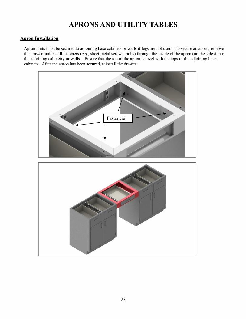
Apron Installation
Apron units must be secured to adjoining base cabinets or walls if legs are not used. To secure an apron, remove the drawer and install fasteners (e.g., sheet metal screws, bolts) through the inside of the apron (on the sides) into the adjoining cabinetry or walls. Ensure that the top of the apron is level with the tops of the adjoining base cabinets. After the apron has been secured, reinstall the drawer.
Fasteners
24
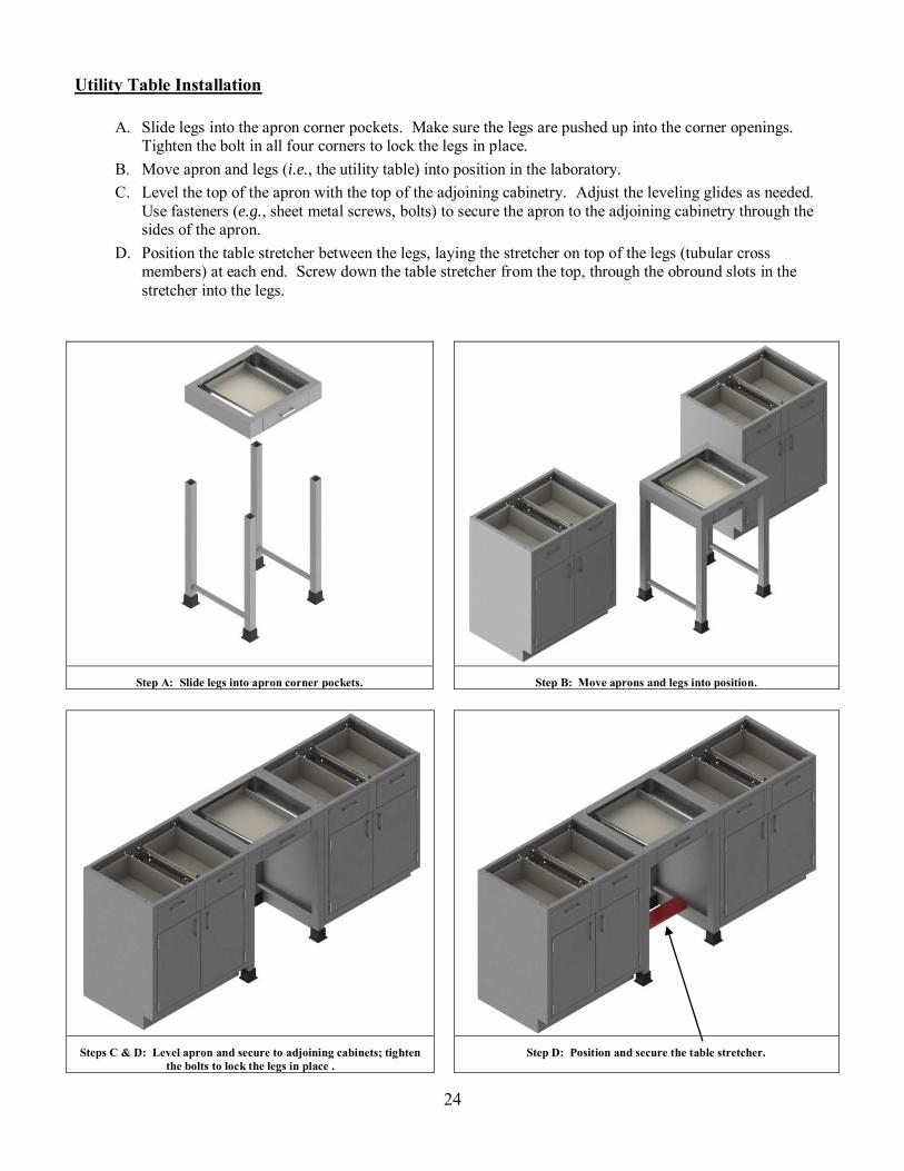
Utility Table Installation
A. Slide legs into the apron corner pockets. Make sure the legs are pushed up into the corner openings. Tighten the bolt in all four corners to lock the legs in place.
B. Move apron and legs (i.e., the utility table) into position in the laboratory. C. Level the top of the apron with the top of the adjoining cabinetry. Adjust the leveling glides as needed.
Use fasteners (e.g., sheet metal screws, bolts) to secure the apron to the adjoining cabinetry through the sides of the apron.
D. Position the table stretcher between the legs, laying the stretcher on top of the legs (tubular cross members) at each end. Screw down the table stretcher from the top, through the obround slots in the stretcher into the legs.
Step A: Slide legs into apron corner pockets. Step B: Move aprons and legs into position.
Steps C & D: Level apron and secure to adjoining cabinets; tighten
the bolts to lock the legs in place . Step D: Position and secure the table stretcher.

25
APPENDIX – FILLER SPECIFICATIONS
Base Cabinet L-Front Fillers
L-front fillers are commonly used to span a gap between the front of a cabinet and a wall. Standard widths are 8” and 14”. Custom widths are also available. These fillers come standard with a slip joint, three filler clips and a toe space filler.
FFL35-8 FFL35-14
FFL29-8 FFL29-14

26
Base Cabinet L-Fillers
L-fillers are commonly used to span a gap between the back of a cabinet and a wall. Standard widths are 1”, 7” and 11”. Custom widths are also available. These fillers come standard with a slip joint and three filler clips.
LF 35-1 LF35-7 LF 35-11
LF 29-1 LF29-7 LF 29-11
27
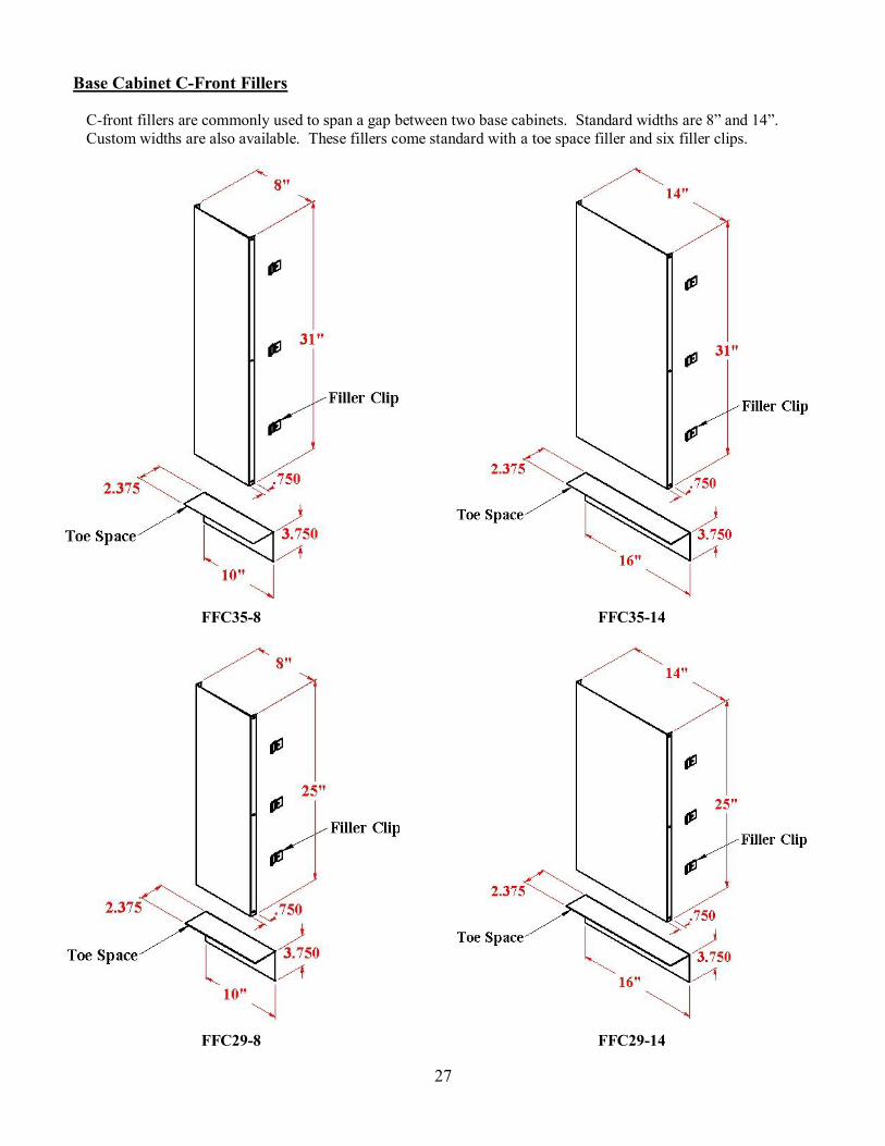
Base Cabinet C-Front Fillers
C-front fillers are commonly used to span a gap between two base cabinets. Standard widths are 8” and 14”. Custom widths are also available. These fillers come standard with a toe space filler and six filler clips.
FFC35-8 FFC35-14
FFC29-8 FFC29-14

28
Base Cabinet C-Fillers
C-fillers are commonly used to span a gap between two base cabinets at the end of an island assembly. Standard widths are 8” and 14”. Custom widths are also available. These fillers come standard with six filler clips.
CF35-8 CF35-14
CF29-8 CF29-14

29
Base Cabinet Inside Corner Fillers
Inside corner fillers are commonly used where two base cabinets come together in a corner. These fillers are available in three standard sizes, as shown below. Custom sizes are also available. These fillers come standard with a toe space filler and six filler clips.
ICF 3501 ICF3502 ICF3504
ICF 2901 ICF2902 ICF2904

30
Wall Case Front Fillers
Wall case front fillers are commonly used where a filler is needed between the front of a wall case and a wall. These fillers are available in four heights (24”, 30”, 36” and 42”). Please specify the desired width (the “W” dimension shown below) when ordering. These fillers come standard with four or five filler clips, depending upon the filler’s height.
Fillers for Standard Depth (13”) Wall Cases Fillers for 16” Deep Wall Cases
WCFF24-Spec Width WCFF30-Spec Width WCFF36-Spec Width WCFF48-Spec Width
WCFF24-Spec Width-16 WCFF30-Spec Width-16 WCFF36-Spec Width-16 WCFF48-Spec Width-16

31
Wall Case Inside Corner Fillers
Wall case inside corner fillers are commonly used where two wall cases come together in a corner. These fillers are available in four heights (24”, 30”, 36” and 42”). These fillers come standard with ten filler clips.
Fillers for 13” Deep Wall Cases Fillers for 16” Deep Wall Cases
WCCF24-13 WCCF30-13 WCCF36-13 WCCF48-13
WCCF24-16 WCCF30-16 WCCF36-16 WCCF48-16
32
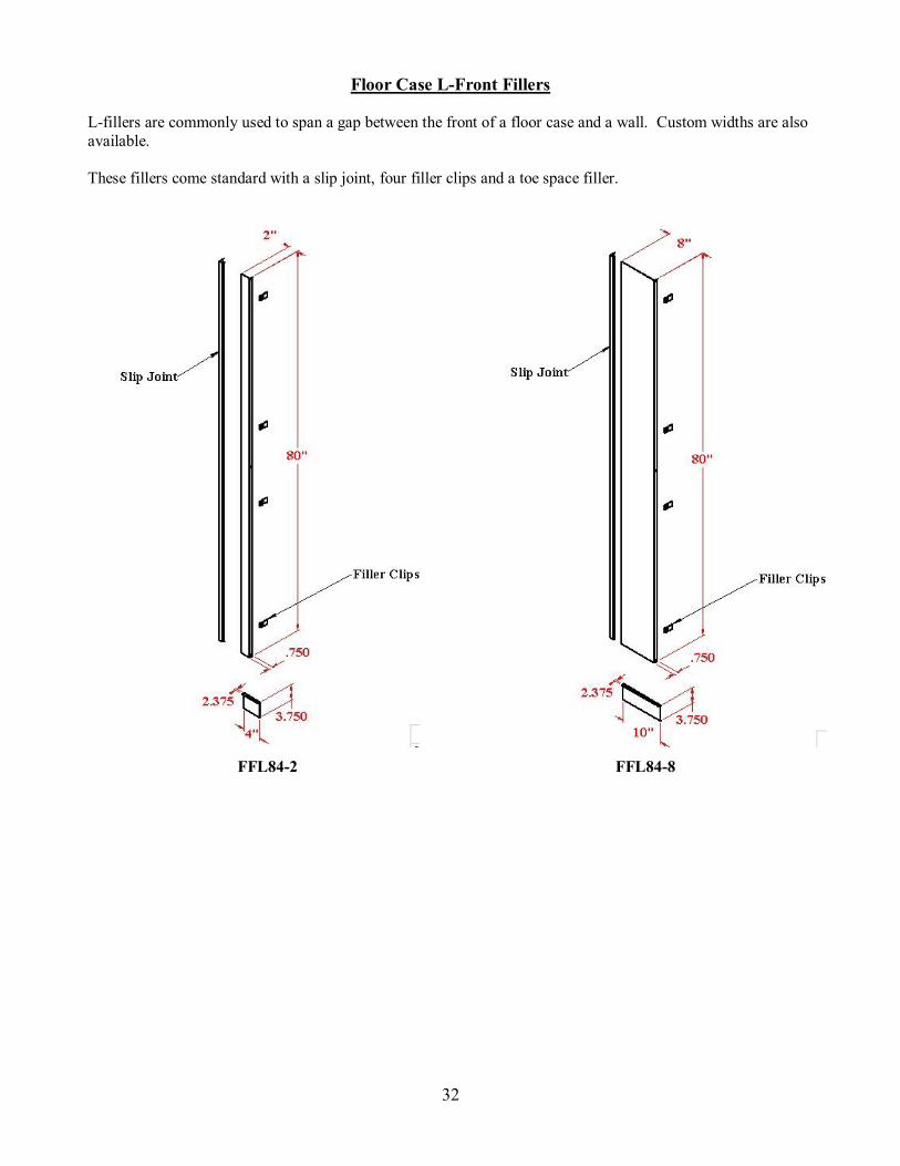
Floor Case L-Front Fillers
L-fillers are commonly used to span a gap between the front of a floor case and a wall. Custom widths are also available. These fillers come standard with a slip joint, four filler clips and a toe space filler.
FFL84-2 FFL84-8

(866) 612 [email protected]
1112 Swenson Blvd.Elgin, Texas 78621
CONTACT INFORMATION
For any questions or concerns contact us