Embed Size (px)
Citation preview

MN
-750
• (
0612
02)
• E
CR
725
9
For maximum effectiveness and safety, please read these instructions completely before proceeding with installation.
Failure to read these instructions can result in an incorrect installation.
INSTALLATION GUIDE
Kits 25850 and 25854Single Gauge Analog Compressor Systems
Kit #25850 with standard duty compressor
Kit #25854 with heavy duty compressor
IntroductionThe purpose of this publication is to assist with the installation of the LoadController / Single onboard air management system.
It is important to read and understand the entire installation guide before beginning installation or performing any maintenance, service or repair. The information here includes a hardware list and step-by-step installation information.
IMPORTANT SAFETY NOTICEThe installation of this kit does not alter the Gross Vehicle Weight Rating (GVWR) or payload of the vehicle. Check your vehicle’s owner’s manual and do not exceed the maximum load listed for your vehicle.
Gross Vehicle Weight Rating: The maximum allowable weight of the fully loaded vehicle (including passengers and cargo). This number — along with other weight limits, as well as tire, rim size and inflation pressure data — is shown on the vehicle’s Safety Compliance Certification Label.
Payload: The combined, maximum allowable weight of cargo and passengers that the truck is designed to carry. Payload is GVWR minus the Base Curb Weight.
NOTATION EXPLANATIONHazard notations appear in various locations in this publication. Information which is highlighted by one of these notations must be observed to help minimize risk of personal injury or possible improper installation which may render the vehicle unsafe. Notes are used to help emphasize areas of procedural importance and provide helpful suggestions. The following definitions explain the use of these notations as they appear throughout this guide.
INDICATES IMMEDIATE HAZARDS WHICH WILL RESULT IN SEVERE PERSONAL INJURY OR DEATH.
INDICATES HAZARDS OR UNSAFE PRACTICES WHICH COULD RESULT IN SEVERE PERSONAL INJURY OR DEATH.
INDICATES HAZARDS OR UNSAFE PRACTICES WHICH COULD RESULT IN DAMAGE TO THE MACHINE OR MINOR PERSONAL INJURY.
Indicates a procedure, practice or hint which is important to highlight.
DANGER
NOTE
WARNING
CAUTION
Load Controller / Single

Low PressureSensor Firewall
Fuse Box
Air Springs(previously installed)
(A1) Standard Duty Compressor
Harness
Analog Single Gauge
Power Wire
PowerWire
Fuse Adapter
In Line15 amp Fuse
Inflation Valve
Grommet
Ground
Harness
Relay
- OR -
(A2) Heavy Duty CompressorGround
Power wireFilter Compression FittingLeader Hose
Installation DiagramAdapter #1
Adapter #2
Adapter #3 *
Adapter
Fuse
* Uses 3/16 (smaller) Female Push On Connector
fig. 1
Load Controller / Single

Hardware List Item Part # Description . . . . . . . . . . . . . . . . . . . . . . . . . . . . . . . Qty A1 16060 Standard Duty Compressor ................1 A2 16092 Heavy Duty Compressor .....................1 B 25194 Analog Single Gauge ..........................1 C 26512 Harness, Single Analog Gauge...........1 D 21952 Tee, 1/8 FNPT X 1/4 PTC ...................1 E 24558 Sensor, 5 PSI ......................................1 F 20946 1/4” Air Line, “DOT” ........................... 25’ G 25196 Gauge Mounting Kit ............................1 H 10463 Grommet .............................................1 I 24652 Spade Fuse, 15 Amp (ATC)................1 J 24539 Fuse Holder (ATC/ATO) .....................1 K 24752 Center Butt, 12-10 GA Shrink Tube ....2 L 24524 3/16” Terminal, FSpd ..........................1 M 24595 FSpd Terminal, 12 GA ........................1 N 24543 Fuse, AGC Tap In ...............................1 O 24561 Mini Fuse Adapter ...............................1 P 24542 ATC/ATO Fuse Tap In 1/4 ..................1 Q 24594 1/4” Terminal, FSpd 16 GA .................4 R 10466 8” Zip Tie .............................................5 S 21838 Tee Union 1/4” X 1/4” PTC .................3 T 17441 #8-18X1” Tek Screw ...........................2
Load Controller / Single
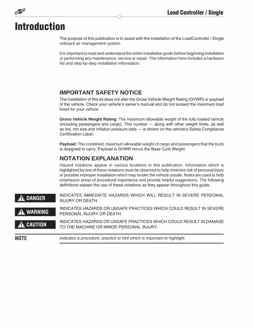
Single Analog Gauge Electrical Schematic
fig. 2
Load Controller / Single
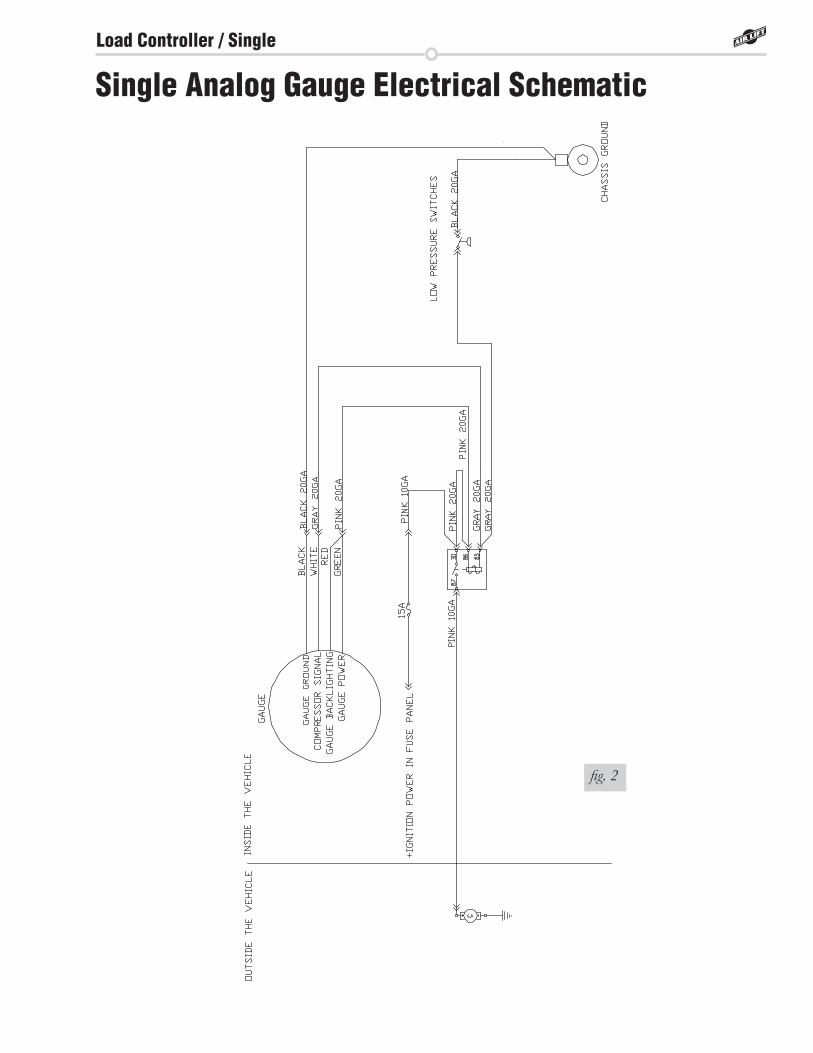
Single Analog Gauge Mounting Options
fig. 3
Single analog gauge mounting hardware on bottom of gauge
fig. 4
Single analog gauge mounting hardware on top of gauge
fig. 5
Back of analog gauge
AirlinePower Wires
fig. 6 Optional Dashboard Mounting(Exploded View)
Load Controller / Single
Installing the Load Controller / Single SystemGETTING STARTED
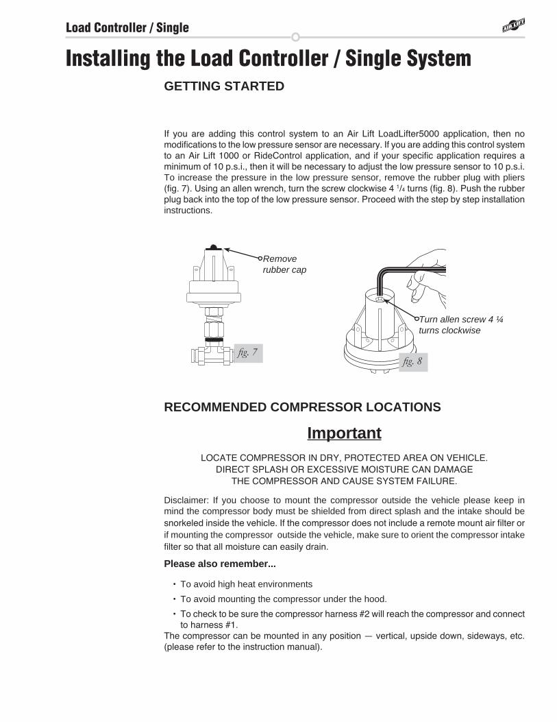
If you are adding this control system to an Air Lift LoadLifter5000 application, then no modifications to the low pressure sensor are necessary. If you are adding this control system to an Air Lift 1000 or RideControl application, and if your specific application requires a minimum of 10 p.s.i., then it will be necessary to adjust the low pressure sensor to 10 p.s.i. To increase the pressure in the low pressure sensor, remove the rubber plug with pliers (fig. 7). Using an allen wrench, turn the screw clockwise 4 1/4 turns (fig. 8). Push the rubber plug back into the top of the low pressure sensor. Proceed with the step by step installation instructions.
RECOMMENDED COMPRESSOR LOCATIONS
Important LOCATE COMPRESSOR IN DRY, PROTECTED AREA ON VEHICLE.
DIRECT SPLASH OR EXCESSIVE MOISTURE CAN DAMAGE THE COMPRESSOR AND CAUSE SYSTEM FAILURE.
Disclaimer: If you choose to mount the compressor outside the vehicle please keep in mind the compressor body must be shielded from direct splash and the intake should be snorkeled inside the vehicle. If the compressor does not include a remote mount air filter or if mounting the compressor outside the vehicle, make sure to orient the compressor intake filter so that all moisture can easily drain.
Please also remember . . .
• To avoid high heat environments
• To avoid mounting the compressor under the hood.
• To check to be sure the compressor harness #2 will reach the compressor and connect to harness #1.
The compressor can be mounted in any position — vertical, upside down, sideways, etc. (please refer to the instruction manual).
fig. 7
Remove rubber cap
fig. 8
Turn allen screw 4 ¼ turns clockwise
Load Controller / Single
STEP BY STEP INSTALLATION
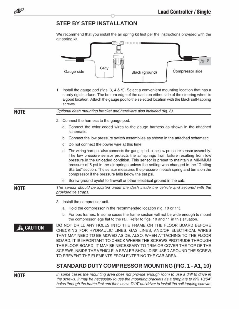
We recommend that you install the air spring kit first per the instructions provided with the air spring kit.
1. Install the gauge pod (figs. 3, 4 & 5). Select a convenient mounting location that has a sturdy rigid surface. The bottom edge of the dash on either side of the steering wheel is a good location. Attach the gauge pod to the selected location with the black self-tapping screws.
Optional dash mounting bracket and hardware also included (fig. 6).
2. Connect the harness to the gauge pod.
a. Connect the color coded wires to the gauge harness as shown in the attached schematic.
b. Connect the low pressure switch assemblies as shown in the attached schematic.
c. Do not connect the power wire at this time.
d. The wiring harness also connects the gauge pod to the low pressure sensor assembly. The low pressure sensor protects the air springs from failure resulting from low pressure in the unloaded condition. This sensor is preset to maintain a MINIMUM pressure of 5 psi in the air springs unless the setting was changed in the “Getting Started” section. The sensor measures the pressure in each spring and turns on the compressor if the pressure falls below the set psi.
e. Screw ground eyelet to firewall or other electrical ground in the cab.
The sensor should be located under the dash inside the vehicle and secured with the provided tie straps.
3. Install the compressor unit.
a. Hold the compressor in the recommended location (fig. 10 or 11).
b. For box frames: In some cases the frame section will not be wide enough to mount the compressor legs flat to the rail. Refer to figs. 10 and 11 in this situation.
DO NOT DRILL ANY HOLES INTO THE FRAME OR THE FLOOR BOARD BEFORE CHECKING FOR HYDRAULIC LINES, GAS LINES, AND/OR ELECTRICAL WIRES THAT MAY NEED TO BE MOVED ASIDE. ALSO, WHEN ATTACHING TO THE FLOOR BOARD, IT IS IMPORTANT TO CHECK WHERE THE SCREWS PROTRUDE THROUGH THE FLOOR BOARD. IT MAY BE NECESSARY TO TRIM OR COVER THE TOP OF THE SCREWS INSIDE THE VEHICLE. A SEALER SHOULD BE USED AROUND THE SCREW TO PREVENT THE ELEMENTS FROM ENTERING THE CAB AREA.
STANDARD DUTY COMPRESSOR MOUNTING (FIG . 1 - A1, 10)In some cases the mounting area does not provide enough room to use a drill to drive in the screws. It may be necessary to use the mounting brackets as a template to drill 13/64” holes through the frame first and then use a 7/16” nut driver to install the self tapping screws.
NOTE
NOTE
CAUTION
NOTE
fig. 9
Compressor sideGauge side Black (ground)Gray
Load Controller / Single

HEAVY DUTY COMPRESSOR MOUNTING (FIG . 1 - A2, 11)Using the compressor as a template, drill holes and mount the compressor using the black mounting hardware that comes in the box containing the compressor.
Attach the compressor ground wire to one of the mounting screws (fig. 1).
AIR LINE AND POWER WIRES ROUTING FOR THE STANDARD DUTY COMPRESSOR:1. Push the air line onto the barb fitting on the compressor. Make sure the air line covers
all barbs. A small amount of water or lubricant and pushing with a slight circular motion will ease installation (fig. 12).
fig. 12
Air line
Ground Power (red) wiresBarbed fitting/check valve
NOTE
fig. 11
Frame
Floor plan
fig. 10
Floor planFrame
L-bracketSupplied self tapping screw
¼” Bolt and nut will need to be provided if the L-bracket is fabricated.
NOTE
Load Controller / Single
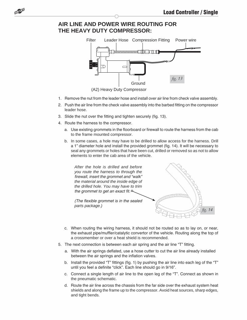
(A2) Heavy Duty CompressorGround
Power wireFilter Compression FittingLeader Hose
AIR LINE AND POWER WIRE ROUTING FOR THE HEAVY DUTY COMPRESSOR:
1. Remove the nut from the leader hose and install over air line from check valve assembly.
2. Push the air line from the check valve assembly into the barbed fitting on the compressor leader hose.
3. Slide the nut over the fitting and tighten securely (fig. 13).
4. Route the harness to the compressor.
a. Use existing grommets in the floorboard or firewall to route the harness from the cab to the frame mounted compressor.
b. In some cases, a hole may have to be drilled to allow access for the harness. Drill a 1” diameter hole and install the provided grommet (fig. 14). It will be necessary to seal any grommets or holes that have been cut, drilled or removed so as not to allow elements to enter the cab area of the vehicle.
c. When routing the wiring harness, it should not be routed so as to lay on, or near, the exhaust pipe/muffler/catalytic convertor of the vehicle. Routing along the top of a crossmember or over a heat shield is recommended.
5. The next connection is between each air spring and the air line “T” fitting.
a. With the air springs deflated, use a hose cutter to cut the air line already installed between the air springs and the inflation valves.
b. Install the provided “T” fittings (fig. 1) by pushing the air line into each leg of the “T” until you feel a definite “click”. Each line should go in 9/16”.
c. Connect a single length of air line to the open leg of the “T”. Connect as shown in the pneumatic schematic.
d. Route the air line across the chassis from the far side over the exhaust system heat shields and along the frame up to the compressor. Avoid heat sources, sharp edges, and tight bends.
fig. 14
After the hole is drilled and before you route the harness to through the firewall, insert the grommet and “walk” the material around the inside edge of the drilled hole. You may have to trim the grommet to get an exact fit.
(The flexible grommet is in the sealed parts package.)
fig. 13
Load Controller / Single
NOTE
CAUTION
e. Route air lines into cab from “T” fitting and attach to pressure switch assembly as shown in the pneumatic schematic.
f. Route air lines from low pressure switch to gauge barb.
g. Press air line over gauge barb. Water or lube may assist in securing air lines over the barb. A circular motion will assist in installation.
6. Connect the power wire to fused ignition.
a. Route it to the vehicle fuse box.
b. Determine which open terminal (accessory, etc.) works only when the key is in the “on” or accessory position (or refer to the owners manual for an available accessory fuse). The terminal should have an amperage rating higher than the 15 amp in-line fuse.
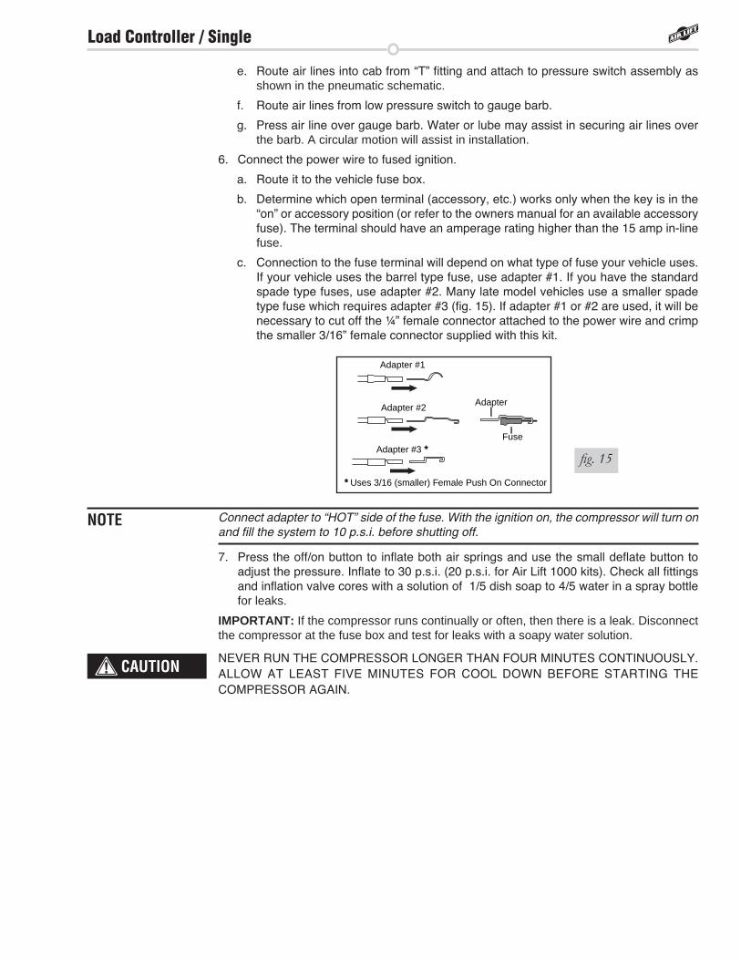
c. Connection to the fuse terminal will depend on what type of fuse your vehicle uses. If your vehicle uses the barrel type fuse, use adapter #1. If you have the standard spade type fuses, use adapter #2. Many late model vehicles use a smaller spade type fuse which requires adapter #3 (fig. 15). If adapter #1 or #2 are used, it will be necessary to cut off the ¼” female connector attached to the power wire and crimp the smaller 3/16” female connector supplied with this kit.
Connect adapter to “HOT” side of the fuse. With the ignition on, the compressor will turn on and fill the system to 10 p.s.i. before shutting off.
7. Press the off/on button to inflate both air springs and use the small deflate button to adjust the pressure. Inflate to 30 p.s.i. (20 p.s.i. for Air Lift 1000 kits). Check all fittings and inflation valve cores with a solution of 1/5 dish soap to 4/5 water in a spray bottle for leaks.
IMPORTANT: If the compressor runs continually or often, then there is a leak. Disconnect the compressor at the fuse box and test for leaks with a soapy water solution.
NEVER RUN THE COMPRESSOR LONGER THAN FOUR MINUTES CONTINUOUSLY. ALLOW AT LEAST FIVE MINUTES FOR COOL DOWN BEFORE STARTING THE COMPRESSOR AGAIN.
Adapter #1
Adapter #2
Adapter #3 *
Adapter
Fuse
* Uses 3/16 (smaller) Female Push On Connector
fig. 15
Load Controller / Single
Frequently asked questions
Q . Will installing air springs increase the weight ratings of a vehicle? No. Adding air springs will not change the weight ratings (GAWR, GCWR and/or GVWR)
of a vehicle. Exceeding the GVWR is dangerous and voids the Air Lift warranty.
Q . Is it necessary to keep air in the air springs at all time and how much pressure will they need?
The minimum air pressure should be maintained at all times. The minimum air pressure keeps the air spring in shape, ensuring that it will move throughout its travel without rubbing or wearing on itself.
Q . Is it necessary to add a compressor system to the air springs? No. Air pressure can be adjusted with any type of compressor as long as it can produce
sufficient pressure to service the springs. Even a bicycle tire pump can be used, but it’s a lot of work.
Q . How long should air springs last? If the air springs are properly installed and maintained they can last indefinitely.
Q . Will raising the vehicle on a hoist for service work damage the air springs? No. The vehicle can be lifted on a hoist for short-term service work such as tire rotation
or oil changes. However, if the vehicle will be on the hoist for a prolonged period of time, support the axle with jack stands in order to take the tension off of the air springs.
Tuning the air pressure
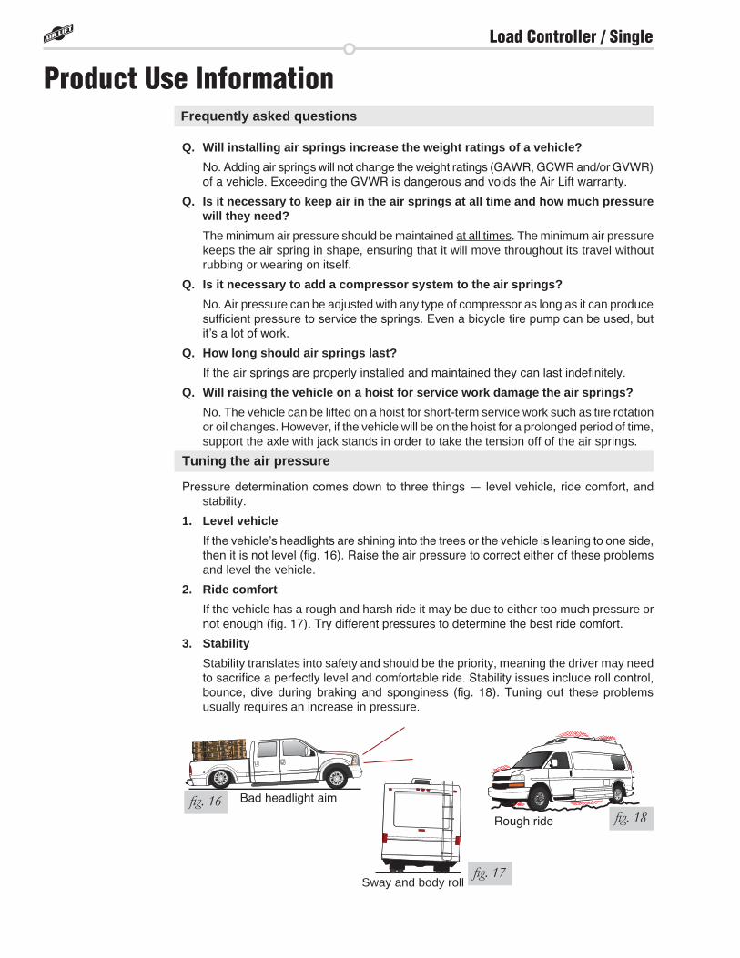
Pressure determination comes down to three things — level vehicle, ride comfort, and stability.
1 . Level vehicle If the vehicle’s headlights are shining into the trees or the vehicle is leaning to one side,
then it is not level (fig. 16). Raise the air pressure to correct either of these problems and level the vehicle.
2 . Ride comfort If the vehicle has a rough and harsh ride it may be due to either too much pressure or
not enough (fig. 17). Try different pressures to determine the best ride comfort.
3 . Stability Stability translates into safety and should be the priority, meaning the driver may need
to sacrifice a perfectly level and comfortable ride. Stability issues include roll control, bounce, dive during braking and sponginess (fig. 18). Tuning out these problems usually requires an increase in pressure.
Bad headlight aimfig. 16
Sway and body rollfig. 17
Rough ride fig. 18
Product Use Information
Load Controller / Single
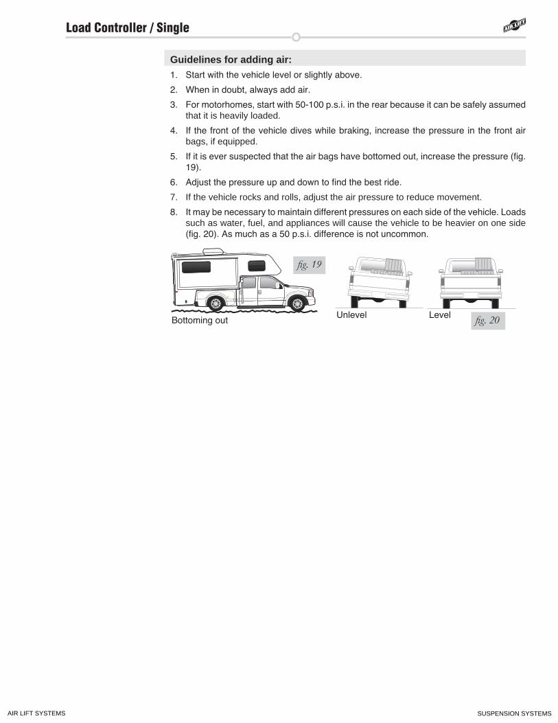
Guidelines for adding air:1. Start with the vehicle level or slightly above.
2. When in doubt, always add air.
3. For motorhomes, start with 50-100 p.s.i. in the rear because it can be safely assumed that it is heavily loaded.
4. If the front of the vehicle dives while braking, increase the pressure in the front air bags, if equipped.
5. If it is ever suspected that the air bags have bottomed out, increase the pressure (fig. 19).
6. Adjust the pressure up and down to find the best ride.
7. If the vehicle rocks and rolls, adjust the air pressure to reduce movement.
8. It may be necessary to maintain different pressures on each side of the vehicle. Loads such as water, fuel, and appliances will cause the vehicle to be heavier on one side (fig. 20). As much as a 50 p.s.i. difference is not uncommon.
fig. 19
Bottoming out Unlevel Level fig. 20
Load Controller / Single
AIR LIFT SYSTEMS SUSPENSION SYSTEMS


![A Review of Biogas Purification through Chemical Absorptioniieng.org/images/proceedings_pdf/1468E1114022.pdf · Fig. 3a Chemical purification setup line diagram [27] Fig. 3b Line](https://img.pdfslide.us/doc/110x75/5ea7efc20c5c8e22d7330e7b/a-review-of-biogas-purification-through-chemical-fig-3a-chemical-purification-setup.jpg)