Embed Size (px)
Citation preview

Air Leaks M Ringger and P Hartmann
Swiss Federal Laboratories for Materials Testing and Research Oberlandstrasse 129 8600 Dubendorf/Zurich Switzerland
1 Abstract
This investigation was performed to evaluate the effectiveness of detecting air leaks in typical constructions through the measurement of sound transmission. The sound transmission of various slits was measured. These were designed to simulate field constructions. Due to the fundamental difference between steady airflow and sound propagation, it was concluded that the method fails, particularly in the case of foil-covered slits and slits coupled to damped cavities.
2 Purpose of the Investigation
The study was undertaken to determine whether an insitu acoustical measurement could be utilized to trace air leaks. A requirement of the method was the use of everyday sound level meters, thus avoiding the need for sophisticated acoustical instruments in the field. At the outset, a literature survey was performed. The findings are compiled in a bibliography at the end of this article.
A straightforward method proposed in the literature is the measurement of sound transmission: a loudspeaker is placed on one side of the construction and the sound pressure level is measured on both sides with a simple sound level meter located near the surface of the specimen. Slits or holes are indicated by an increase in sound pressure level.
This method was investigated further. In order to obtain quantitative data, the sound transmission was measured using well-defined slits. Slit dimensions and constructions comparable to those found in field constructions were utilized with a view toward future applications.
The following measurements were performed:
1. Sound transmission through simple slits of various widths; 2. Sound transmission through slits containing a rectangular bend; 3. Sound transmission through slits covered with various foils; 4. Sound transmission through slits coupled to a damped cavity.
6 I
--- - -- ---i
3 Measurements
The tests were performed in a laboratory facility for the measurement of the sound transmission of doors. The main structural member had a high transmission loss. It was provided with additional elements in the form of slits. Figure 1 shows the main member from both sides. Two large gaps were cut into it. The first gap was then closed by a 1 O cm thick wooden beam. This was designated as the "reference beam". The other gap was closed by two beams, thus creating a slit which could I be adjusted to different widths.
I _11 j
Al~~ Reference Beam Q) Slit Q Smm •
© i----.,f MicrophoneG) IOOmm
Fig. 1 Illustration and schematic view of main member with the two gaps, and with the reference beam and slit fastened to it.
The average sound pressure level in the sender room was measured. On the opposite side, the sound pressure level was measured at a distance of 0.5 cm from the slit. Sound transmission occurred not only through the slit, but also through the main member itself. In order to correct for the latter sound transmission, the sound pressure level near the surface of the reference beam was also measured.
Air Infiltration Review, Vol.11, No.I, December 1989
The measurements were carried out with a real-time 1/3 octave-band analyzer (Norton 830). All bands from 200 The following results were obtained: Hz up to 10 kHz were considered.
Since the method was intended to detect slits which are not apparent to the naked eye, small slit widths were employed, namely 0.5 mm, 1.0 mm, 1.5 mm and 2.0 mm. The interpretation of the measurements was to be as simple as possible. With this in mind, the difference Os was defined:
where
P1 = sound pressure level 0.5 cm from the slit P2 = average sound pressure level in the sender room.
A similar difference was defined for the reference beam, designated as Do.
Figure 2 shows the spectrum of the negative Do values for the reference beam.
A decrease in Do is noted at high frequencies. This is attributed to sound transmission through the slit and other leaks. It results in a rather high sound pressure In the receiver room, thus increasing the apparent sound transmission of the reference beam.
By taking the difference Ts = Os - Do, the increase in sound pressure due to the presence of the slit is obtained. The results for the various slits are presented below in terms of this quantity Ts. A more accurate way of defining the sound transmission would be in terms of the acoustic energy transmitted through the slit. However, consistent with the goal of trying to detect leaks with a simple sound level meter, only the differences in sound pressure level will be considered here.
._/ V"\ LI \
V' \ I
\ ua " .. .. n u~
IH.z l .-.-•>
Fig. 2 Spectrum at reference beam compared with sender room (Do)
Air Infiltration Review, Vol.11, No.I, December 1989 I
Simple slit
Figure 3 shows a sketch of the elements and the results for a simple slit. In accordance with theory, a peak In the sound transmission Is observed at approximately 1250-1600 Hz, resp. a dip at 2500 Hz. This dip occurs when the depth of the slit Is an integer multiple of the half-wavelength. The peak and dip can also be observed with the other slit types. A further decrease In sound transmission, not explained by theory, is seen at the upper end of the frequency range. This occurs because the quantity Ts represents the difference between the sound pressure at the slit and at the reference beam. As mentioned above, the apparent sound transmission of the reference beam is reduced by the sound transmission of the slit itself, thus in turn reducing the difference Ts.
! I
•lln1'0 •P11•n 1Q Olll - 1
Fig. 3 Sound transmission Ts of simple slits: 1) 0.5mm; 2) 1.0mm; 3) 1.5mm and 4) 2.0mm
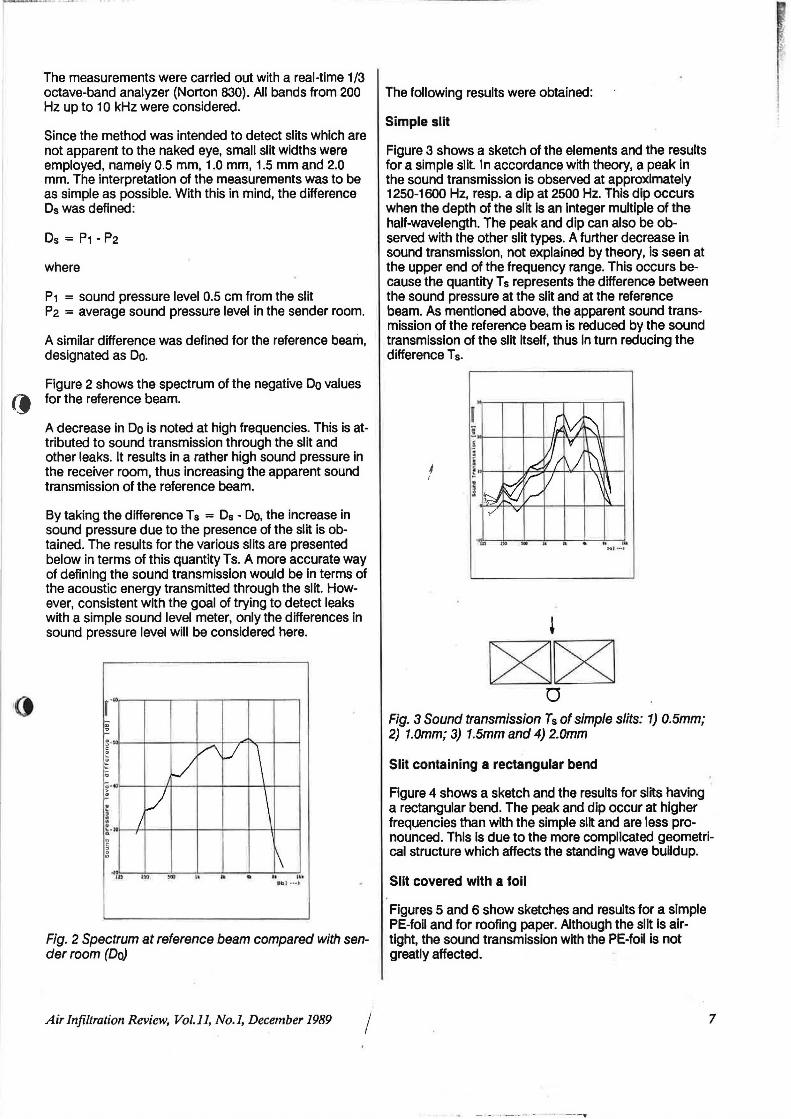
Slit containing a rectangular bend
Figure 4 shows a sketch and the results for slits having a rectangular bend. The peak and dip occur at higher frequencies than with the simple slit and are less pronounced. This is due to the more complicated geometrical structure which affects the standing wave buildup.
Slit covered with a foil
Figures 5 and 6 show sketches and results for a simple PE-foil and for roofing paper. Although the slit is airtight, the sound transmission with the PE-foil is not greatly affected.
- - - ·--- ·- -- ---..
7

Fig. 4 Sound transmission Ts of slits containing a rectangular bend: 1) 0.5mm; 2) 1.0mm; 3) 1.5mm and 4) 2.0mm
' I ~J ~ l
I ~ v
·~ 0 ' 1\
- . . . W• •
Fig. 5 Sound transmission Ts of slits covered with a PEfoil: 1) 0.5mm; 2) 1.0mm; 3) 1.5mm and 4) 2.0mm
Fig. 6 Sound Transmission Ts of silts covered with roofing paper: 1) 0.5mm; 2) 1.0mm; 3) 1.5mm and 4) 2.0mm
8
I
- - .. . .. --l
C8J~ 0
Fig. 7 Sound transmission Ts of slits coupled to a damped cavity: 1) 0.5mm; 2) 1.0mm; 3) 1.5mm and 4) 2.0mm
This measurement clearly illustrates the difference be-tween steady air flow and sound propagation. Light- t weight foils represent only a small resistance for the vibrating air molecules (sound), but allow no steady air flow. It is interesting to note that in the case of the PE-foil, the sound transmission is even higher than that for the simple slit. This is possibly due to a better match of the radiation impedance between the slit and room .
Slit coupled to a damped cavity
As seen from Figure 7, the sound transmission is effectively reduced, although air is able to pass freely through the slit. This type of construction ls often used for doors, where it is necessary to reduce sound transmission through the slit between the door and the floor.
Discussion
A real-time analyzer is not commonly available for field measurements. Only the linear or A-weighted sound level can be measured. In the following table, the linear difference (calculated from the energetic sum of the 1/3 t octave-bands) is presented.
Slit type Level difference in dB 01-near) (slit - ref. beam)
simple slit 11.3 slit with rectanaular bend 19.2 ...... covered slit (foil) 12.4 ~ covered slit (roofing 12.1 oaoer) slit coupled to damped 1.4 cavitv
These results are somewhat arbitrary, since they depend on the spectrum in the sender room (in this case pink noise). Nevertheless, it is obvious that the overall level differences are neither consistent not reliable. The
Air Infiltration Review, Vol.11, No.1, December 1989
11

1~, .... ~,.•c·-•·-'·'"'"~·"'· '.· .. . · ·• •
I
0
method fails in two cases which occur frequently in the field.
Indeed, an operator would suspect that a foil was located in or at the end of the slit by examining the spectrum of the sound transmission, as was done during this investigation. However, this contradicts our postulated requirement for a simple method without the need of sophisticated instruments. Likewise, in the case of the slit coupled to a damped cavity, it would require a more elaborate acoustic measurement to establish that a degree of sound transmission was still present.
The method fails because the relation between air-flow and sound transmission (by analogy, DC and AC) is ambiguous. Electrically, the slit with a foil can be compared to a series condenser (block direct flow) and the slit coupled to a cavity to a parallel condenser (reducing AC flow).
Bibliography
General theory of sound transmission through openings
"On the transmission of acoustic waves through a circular channel of a thick wall". Y Normura and S lnawashiro, Sci Rep, Tohuko Univ (1), 12BA1960U, 57.
"The "sound insulation" of circular and slit-shaped apertures" MC Gomperts, Acustica 14(1964), 1.
"Approximation to the diffraction of sound by a circular aperture in rigid wall of finite thickness", G P Wilson and WW Soroka, JASA 37 (1965), 286.
"Measurement of the transmission loss of a finite-depth aperture", GP Wilson, JASA, 37 (1965), 191.
''The sound transmission loss of circular and slit-shaped apertures in walls", M C Gomperts and T Kihlman, Acustica, 18 (1967), 144.
"Schalldruchgang durch Locher und Schlitze mit Absorberfullung und Versiegelung", F P Mechel, Acustica 61 (1986), 87.
Measurements of the sound insulation of openings on every day building elements.
"Schalldammung von Fugen mit porosen Dichtungsstreifen", K Gosele und U Decker, DAGA, 1972.
"Die Schalldammung von Fugen - Moglichkeiten ihrer Verbesserung", H Ertel, IBP-Mitteilung Nr. 41 (1978).
"Experimentelle Untersuchungen zur Schalldammung von Toren und Wandfugen", H Ertel, Zs. Warme-KalteSchall-Brandschutz, Aug. 1980.
Air Infiltration Review, Vol.11, No.I, December 1989 i i
Comparisons between air leakage and sound transmission
I
"Acoustical and thermal performance of exterior residential walls, doors and windows", HJ Sabine, MB Lacher, D R Flynn and T L Quindry, National Bureau of Standards, Nov, 1975.
"Entwicklung einer Akustischen Messmethode zur Ermittlung der Luftdurchlassigkeit von Bauelementen im eingebauten Zustand", Kurzber, Bauforschung 19 (1978), 521.
"Energy optimization of outer window-and-door frames", E Brosio, W Esposti, L Latteoli and U Monaco, Institute Centrale per l'lndustrializziazione e la Tecnologia Edilizia, 1978.
"Acoustic location of infiltration openings in buildings", D N Keast, Brookhaven National Laboratory, Report Nr: BNL 50952, 1978.
"A relation between transmission loss and air infiltration characteristics in windows", G Benedetto and E Brosio, lstituto Elettrotecnico Nazionale Galileo Ferraris, Turin, 1981. J
' "Listening for air leaks", P Bolton, Popular Science, Feb. 1981, 38.
"A sonic method for building air-leakage measurements", T Sonoda and F Peterson, Appl. Energy 22 (1986), 205.
"Low-frequency measurements of leakage in enclosures", M Sherman and M Modera, Lawrence Berkeley Laboratory, Appl. Sci. Div., 1986.
9