Embed Size (px)
Citation preview
www.vmacair.comwww.vmacair.com
Transmission Mounted Air Compressor (DTM) Owner’s Manual
®
AIR INNOVATEDTM
®
AIR INNOVATEDTM


VMAC - Vehicle Mounted Air CompressorsVMAC Technical Support: 888-241-2289VMAC Knowledge Base: www.kb.vmacair.com
1
Table of ContentsGeneral Information . . . . . . . . . . . . . . . . . . . . . . . . . . . . . . . . . . . . . . . . . . . . . . . . . . . . . . . . . . . 3Safety . . . . . . . . . . . . . . . . . . . . . . . . . . . . . . . . . . . . . . . . . . . . . . . . . . . . . . . . . . . . . . . . . . . . . . . . . 4Safety Precautions . . . . . . . . . . . . . . . . . . . . . . . . . . . . . . . . . . . . . . . . . . . . . . . . . . . . . . . . . . . . 5Warranty . . . . . . . . . . . . . . . . . . . . . . . . . . . . . . . . . . . . . . . . . . . . . . . . . . . . . . . . . . . . . . . . . . . . . . 8System Specifications . . . . . . . . . . . . . . . . . . . . . . . . . . . . . . . . . . . . . . . . . . . . . . . . . . . . . . . . . 10Identifying Your System . . . . . . . . . . . . . . . . . . . . . . . . . . . . . . . . . . . . . . . . . . . . . . . . . . . . . . . 11System Components . . . . . . . . . . . . . . . . . . . . . . . . . . . . . . . . . . . . . . . . . . . . . . . . . . . . . . . . . . 12Operating Principles . . . . . . . . . . . . . . . . . . . . . . . . . . . . . . . . . . . . . . . . . . . . . . . . . . . . . . . . . . 18Upfitter Vehicle Controls . . . . . . . . . . . . . . . . . . . . . . . . . . . . . . . . . . . . . . . . . . . . . . . . . . . . . 20System Operation . . . . . . . . . . . . . . . . . . . . . . . . . . . . . . . . . . . . . . . . . . . . . . . . . . . . . . . . . . . . 21General Maintenance Information . . . . . . . . . . . . . . . . . . . . . . . . . . . . . . . . . . . . . . . . . . . . 23Maintenance and Repair Safety. . . . . . . . . . . . . . . . . . . . . . . . . . . . . . . . . . . . . . . . . . . . . . . 25Regular Inspection Instructions . . . . . . . . . . . . . . . . . . . . . . . . . . . . . . . . . . . . . . . . . . . . . . . 27200 Hour / 6 Month Service . . . . . . . . . . . . . . . . . . . . . . . . . . . . . . . . . . . . . . . . . . . . . . . . . . 31400 Hour / 1 year Service . . . . . . . . . . . . . . . . . . . . . . . . . . . . . . . . . . . . . . . . . . . . . . . . . . . 34Diagnostics and Trouble Shooting . . . . . . . . . . . . . . . . . . . . . . . . . . . . . . . . . . . . . . . . . . . 40Air Receiver Tank . . . . . . . . . . . . . . . . . . . . . . . . . . . . . . . . . . . . . . . . . . . . . . . . . . . . . . . . . . . . 46Recommended Accessories . . . . . . . . . . . . . . . . . . . . . . . . . . . . . . . . . . . . . . . . . . . . . . . . . . . 47Performance Testing and System Adjustments . . . . . . . . . . . . . . . . . . . . . . . . . . . . . . . 48Accessory Products from VMAC . . . . . . . . . . . . . . . . . . . . . . . . . . . . . . . . . . . . . . . . . . . . . . 57Warranty Registration . . . . . . . . . . . . . . . . . . . . . . . . . . . . . . . . . . . . . . . . . . . . . . . . . . . . . . . 64
VMAC - Vehicle Mounted Air CompressorsVMAC Technical Support: 888-241-2289
VMAC Knowledge Base: www.kb.vmacair.com2
Document: 1930283Changes and Revisions
Revision Revision Details Revised byChecked by
ImplementedEng.Tech. Qual.
Mech. Elec.A Engineering Release MSP SM SM GB AGM 25 April 2016
B ECN 18-027 Add information for DTM70-H MSP CAM SM GB AWG 23 March 2018
C ECN 18-077 Add safety call out on pg 37 MSP CAM N/A GB AWG 11 April 2018
NoticeCopyright © 2018 VMAC Global Technology Inc. All Rights Reserved. These materials are provided by VMAC for informational purposes only, without representation or warranty of any kind, and VMAC shall not be liable for errors or omissions with respect to the materials. The only warranties for VMAC products and services are those set forth in the express warranty statements accompanying such products and services, if any, and nothing herein shall be construed as constituting an additional warranty. Printing or copying of any page in this document in whole or in part is only permitted for personal use. All other use, copying or reproduction in both print and electronic form of any part of this document without the written consent of VMAC is prohibited. The information contained herein may be changed without prior notice.
Printed in Canada
Registered TrademarksAll trademarks mentioned in this manual are the property of their respective owners. VMAC’s use of manufacturers’ trademarks in this manual is for identification of the products only and does not imply any affiliation to, or endorsement of said companies.
Important NoticeThe information contained in this manual is based on sound engineering principles, research, extensive field experience and technical information. Information is constantly changing with the addition of new models, assemblies, service techniques and running OEM changes. If a discrepancy is found in this manual, contact VMAC prior to initiating or proceeding with installation, service, repair or operation. Current information may clarify the issue. Any person with knowledge of such discrepancies, who proceeds to perform service and repair assumes all risks.
Only proven service procedures are recommended. Anyone who departs from the specific instructions provided in this manual must first assure that their safety and that of others is not being compromised and that there will be no adverse effects on the operational safety or performance of the equipment.
VMAC will not be held responsible for any liability, consequential damages, injuries, loss or damage to individuals or to equipment as a result of the failure of any person to properly adhere to standard safety practices or the procedures set out in this manual. Safety should be the first consideration when operating, or performing any service to the equipment. If there are any questions concerning the procedures in this manual, or more information is required, please contact VMAC before beginning repairs.
VMAC - Vehicle Mounted Air CompressorsVMAC Technical Support: 888-241-2289VMAC Knowledge Base: www.kb.vmacair.com
3
IntroductionThis manual provides operating instructions, specifications, adjustment, maintenance and warranty information for VMAC Transmission Mounted Air Compressor systems. Read this manual prior to servicing or operating the compressor system.Follow all safety precautions when servicing or operating the VMAC system as moving drive belts, fan blades and other rotating components pose an extreme hazard. Proper service and repair are important to the safety of the operator and the safe, reliable operation of the equipment. Always use genuine VMAC parts.The procedures described in this manual are the only approved methods of service and operation.
Optional Equipment CompatibilityWhile VMAC strives to design systems compatible with optional OEM equipment (such as running boards), it is impractical to develop systems that accommodate every OEM and aftermarket option or add-on. Whenever possible, VMAC endeavors to advise of compatibility issues in the “Additional Application Information” section of the specific installation manual. Even when specific optional equipment is determined by VMAC to be incompatible, it does not preclude the vehicle upfitter or end user from modifying the optional equipment to make it compatible with the installed VMAC system. VMAC does not warranty or accept responsibility or liability for the fitment, function or safety of any products modified in any way not expressly outlined in the installation manual.
Ordering PartsTo order parts, contact a VMAC dealer. The dealer will ask for the VMAC System ID (see page 11), part number, description and quantity. Locate the nearest dealer online at www.vmacair.com/dealer-locator or call 1-877-912-6605.
General Information
Additional SupportAdditional resources such as installation manuals, illustrated parts lists, the VMAC Knowledge Base, air tool consumption guides, etc. are available at https://www.vmacair.com/support/.
VMAC - Vehicle Mounted Air CompressorsVMAC Technical Support: 888-241-2289
VMAC Knowledge Base: www.kb.vmacair.com4
Safety MessagesThis manual contains various warnings, cautions and notices that must be observed to reduce the risk of personal injury during operation or service, and the possibility that improper operation or service may damage the equipment or render it unsafe.
This symbol is used to call attention to instructions concerning personal safety. Watch for this symbol; it points out important safety precautions, it means, “Attention, become alert! Your personal safety is involved”. Read the message that follows and be aware of the possibility of personal injury or death. As it is impossible to warn of every conceivable hazard, common sense and industry standard safety practices must be observed.
This symbol is used to call attention to instructions on a specific procedure that if not followed may damage or reduce the useful life of the compressor or other equipment.
This symbol is used to call attention to additional instructions or special emphasis on a specific procedure.
Safety
VMAC - Vehicle Mounted Air CompressorsVMAC Technical Support: 888-241-2289VMAC Knowledge Base: www.kb.vmacair.com
5
Harmful VapoursBreathing fuel vapours or engine exhaust can expose you to chemicals known to the State of California to cause cancer and birth defects or other reproductive harm.
• Always start and operate the engine in a well ventilated area.
• Do not breathe engine exhaust, internal combustion engines produce carbon monoxide, a poisonous odorless gas which can cause death. Do not start or operate this compressor in an enclosed area.
• If in an enclosed area, vent the exhaust to the outside and ensure there is adequate access to fresh breathable air..
Burn Hazard• The compressor system gets very hot during operation, contact
with the components or the oil can cause serious injury. Allow sufficient time for the system to cool before performing service.
• Never allow any part of your body to contact the engine or compressor components.
• Do not attempt to service the compressor until it has sufficiently cooled.
As the VMAC compressor system is an industrial grade compressor, it is assumed that the operator has been trained in industry specific safety practices.
Read this information before operating the compressor for the first time. Follow the information and procedures in this manual for operation, maintenance and repair.
Follow all safety precautions for safe operation or service. Moving belts and rotating components are an extreme hazard. Stay clear of all moving parts when the system is operating. Only qualified personnel should perform maintenance and repair on system components and only while the system is properly shut down and depressurized.
Proper service and operation are important to the safety of the operator and the safe, reliable operation of the equipment. Always use genuine VMAC parts.
The procedures described in this manual are effective methods of service and repair. Some procedures may require the use of special tools designed for a specific purpose. Anyone using a replacement part, service procedure or tool must ensure that neither their safety, nor the safe operation of the equipment will be compromised by the replacement part, service procedure or tool selected.
Safety Precautions
VMAC - Vehicle Mounted Air CompressorsVMAC Technical Support: 888-241-2289
VMAC Knowledge Base: www.kb.vmacair.com6
Personal Safety• Follow all safe work practices.
• Do not breathe the compressor air. Vaporized oil is a respiratory hazard.
• Service should only be performed by qualified personnel.
• Always use the appropriate personal protective equipment, particularly eye and hearing protection when operating or servicing air powered equipment.
• Do not leave the vehicle unattended.
Fire and Explosion Hazard• Vaporized oil propelled by high pressure air is a potentially
explosive mixture.
• Fire in the compressor can cause an explosion and flame projection. Should this occur, there is potential for serious injury or death.
• Operate the compressor system in a well ventilated area free of flammable vapors, dust, or other combustible materials.
• Never place objects against or near the compressor components.
• Never expose the AOST or compressor to extreme heat.
• Serious injury or death may result from an air tank explosion.
• Never exceed manufacturer’s maximum air pressure rating.
• Do not repair components, only replace with approved parts.
• Do not tamper with or disable factory safety equipment.
Compressor Air and Oil Hazard• The compressor system is under sufficient pressure that a leak
could force the air/oil mixture through the skin directly into the bloodstream. This could cause serious injury or death.
• Ensure the system is completely depressurized before attempting maintenance or repair.
• Do not use compressed air to clean off clothing or skin, compressed air can penetrate the skin causing serious injury or death.
• Do not service the compressor while it is pressurized or operating.
• Components and hoses under pressure could separate suddenly, causing serious injury or death. If equipped, the air receiver tank must be drained before servicing any components in the compressor system.
• Never adjust or attempt to make any repairs to the system while the engine is running.
VMAC - Vehicle Mounted Air CompressorsVMAC Technical Support: 888-241-2289VMAC Knowledge Base: www.kb.vmacair.com
7
Moving Parts Hazard• Before performing service, disconnect the negative battery cable.
• Avoid contact with drive belts and other moving parts while the system is in operation.
General Warnings• Be attentive for unexplained changes in operation and record any
changes.
• Check the compressor oil level and condition before starting the system. Do not add or change oil while the system is running. Use only approved oil.
• The compressor operates anytime the engine is running.
• Keep hoses and wiring away from hot, sharp, or moving components.
• Use only approved hoses and replacement parts.
• Do not modify the equipment.
• Do not operate the air compressor when fatigued or under the influence of alcohol or drugs.
• Know how to operate the compressor, read this manual prior to operation.
• Inspect equipment before every use.
• Never bypass or disable any of the safety equipment.
• Never adjust or attempt to make any repairs to the compressor system while the engine is running or the air system pressurized. Components and hoses under pressure could fail and cause serious injury or death.
• The vehicle must be in “Park” (for automatic transmissions) or “Neutral” (for manual transmissions) with the park brake or air spring brake fully applied before starting the compressor and at all times during compressor operation.
• Use a regulator in the output line to precisely control the final air delivery pressure.
• Run the system at idle speed under no-load conditions for 1 minute before turning the system off, to allow system cooling and lubrication.
VMAC - Vehicle Mounted Air CompressorsVMAC Technical Support: 888-241-2289
VMAC Knowledge Base: www.kb.vmacair.com8
VMAC Standard Warranty (Limited)For complete warranty information, including both VMAC Standard Warranty (Limited) and VMAC Lifetime Warranty (Limited) requirements, please refer to our current published warranty located at: www.vmacair.com/warranty
If you do not have access to a computer, please contact us and we will be happy to send you our warranty.
VMAC’s warranty is subject to change without notice.
VMAC Lifetime Warranty (Limited)A VMAC Lifetime Limited Warranty is offered on the base air compressor only and only on UNDERHOOD, Hydraulic Driven, Transmission Mounted, Gas and Diesel Engine Driven Air Compressors, Multifunction Power Systems, and other products as defined by VMAC, provided that (i) the purchaser fully completes and submits a warranty registration form within 3 months of purchase, or 200 hours of operation, whichever occurs first; (ii) services are completed in accordance with the Owner’s Manual; (iii) proof of purchase of applicable service kits are made available to VMAC upon request.
The VMAC Lifetime Warranty is applicable to new products shipped on or after 1 October, 2015.
Warranty RegistrationThe VMAC warranty registration form is located near the back of this manual. This warranty registration form must be completed and sent to VMAC at the time of installation for any subsequent warranty claim to be considered valid.
There are 4 ways the warranty can be registered with VMAC:
www.vmacair.com/warranty
(877) 740-3202
VMAC - Vehicle Mounted Air Compressors1333 Kipp Road, Nanaimo, BC, Canada V9X 1R3
Warranty
VMAC - Vehicle Mounted Air CompressorsVMAC Technical Support: 888-241-2289VMAC Knowledge Base: www.kb.vmacair.com
9
VMAC warranty work must be pre-authorized by VMAC. Claims are processed via our dealer network. If you are not a VMAC dealer, please select one to work with via our Dealer Locator: https://www.vmacair.com/dealer-locator/.
1. Communicate with VMAC Technical Support at 1-888-241-2289 to help diagnose/troubleshoot the problem prior to repair. VMAC technical support requires the VMAC System ID, hours on the compressor and mileage on the vehicle.
2. VMAC will provide direction for repair or replacement of the failed components. 3. Failed parts must be held by the dealer for a period of six months, and sent to
VMAC if requested (along with the RMA number) for evaluation, unless otherwise instructed by VMAC.
4. Dealers may login to the VMAC website to view the VMAC Labour Time Guide (under “Agreements”) to see the allowable warranty labour times.
5. Warranty invoices must include the RMA/Service Ticket (CSR) number, VMAC System ID#, hours on the compressor, mileage on the vehicle, and a detailed description of the work performed.
6. VMAC Warranty does not cover consequential damage, overtime charges, mileage, travel time, towing/recovery, cleaning or shop supplies.
7. Dealers submit warranty claims on behalf of the Vehicle Owner/End User affected by the defective part(s). The dealer ensures that all warranty credits are refunded back to the Vehicle Owner/End User who made the initial warranty claim.
For Standard Warranty (Limited): If the completed warranty registration form has not been received by VMAC within 6 months from the date of installation of the Product(s), the warranty period will be deemed to commence 30 days from the date of shipment from VMAC.
For Lifetime Warranty (Limited): The completed warranty registration form must be received by VMAC within 3 months from the date of purchase or 200 hours of operation of the product(s) (whichever occurs first).
Failure to follow this procedure may result in denial of the warranty claim.
VMAC Product Warranty Policies & Warranty Registration can be found on the VMAC website (see previous page for URL).
VMAC Warranty Claim Process
VMAC - Vehicle Mounted Air CompressorsVMAC Technical Support: 888-241-2289
VMAC Knowledge Base: www.kb.vmacair.com10
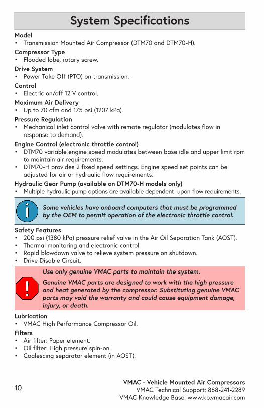
Model• Transmission Mounted Air Compressor (DTM70 and DTM70-H).Compressor Type• Flooded lobe, rotary screw.Drive System• Power Take Off (PTO) on transmission.Control• Electric on/off 12 V control.Maximum Air Delivery• Up to 70 cfm and 175 psi (1207 kPa).Pressure Regulation• Mechanical inlet control valve with remote regulator (modulates flow in
response to demand). Engine Control (electronic throttle control)• DTM70 variable engine speed modulates between base idle and upper limit rpm
to maintain air requirements.• DTM70-H provides 2 fixed speed settings. Engine speed set points can be
adjusted for air or hydraulic flow requirements.Hydraulic Gear Pump (available on DTM70-H models only)• Multiple hydraulic pump options are available dependent upon flow requirements.
System Specifications
Use only genuine VMAC parts to maintain the system.
Genuine VMAC parts are designed to work with the high pressure and heat generated by the compressor. Substituting genuine VMAC parts may void the warranty and could cause equipment damage, injury, or death.
Lubrication• VMAC High Performance Compressor Oil.Filters• Air filter: Paper element. • Oil filter: High pressure spin-on.• Coalescing separator element (in AOST).
Some vehicles have onboard computers that must be programmed by the OEM to permit operation of the electronic throttle control.
Safety Features• 200 psi (1380 kPa) pressure relief valve in the Air Oil Separation Tank (AOST).• Thermal monitoring and electronic control.• Rapid blowdown valve to relieve system pressure on shutdown.• Drive Disable Circuit.

VMAC - Vehicle Mounted Air CompressorsVMAC Technical Support: 888-241-2289VMAC Knowledge Base: www.kb.vmacair.com
11
Identifying Your SystemThe System ID will be requested any time that parts are ordered, when calling for technical support or submitting a warranty claim. The system ID is the preferred method of identifying the system as it serves as a master record of all of the components in the system. The system ID plate is generally found on the radiator cross member, or in some instances, the inner fender or firewall (Figure 1).
An alternative method of identifying the system is via the compressor serial number which is found on a plate attached to the compressor. This is a less desirable method of identifying the system as it may not link back to the original system if it has been replaced.
System ID breakdownThe system ID provides specific information about the system such as the model, revision, production date and the unique identifier (Figure 2).
Figure 1 — System ID location
Figure 2 — System ID breakdown
Model number
Revision letter Production date code
Unique identifier

VMAC - Vehicle Mounted Air CompressorsVMAC Technical Support: 888-241-2289
VMAC Knowledge Base: www.kb.vmacair.com12
System ComponentsThe Transmission Mounted Air Compressor system consists of the following components:
• Air Oil Separator Tank (AOST).• Compressor.• Oil return, Air/Oil discharge hoses.• PTFE oil scavenge and pressure
control tubes.
• Black air brake pressure control tube.• Digital Control Box.• Throttle Control.
AOST
Oil drain
Oil filter
Figure 3 — AOST (front)
Oil supply to compressor
Oil sight glass
Air/oil discharge from
compressor
3/16 in pressure control fitting
Figure 4 — AOST blowdown cap (back)
1/4 in oil scavenge fitting
Blowdown muffler
200 psi pressure relief valve
3/4 in NPT to JIC adaptor
(not included)
VMAC - Vehicle Mounted Air CompressorsVMAC Technical Support: 888-241-2289VMAC Knowledge Base: www.kb.vmacair.com
13
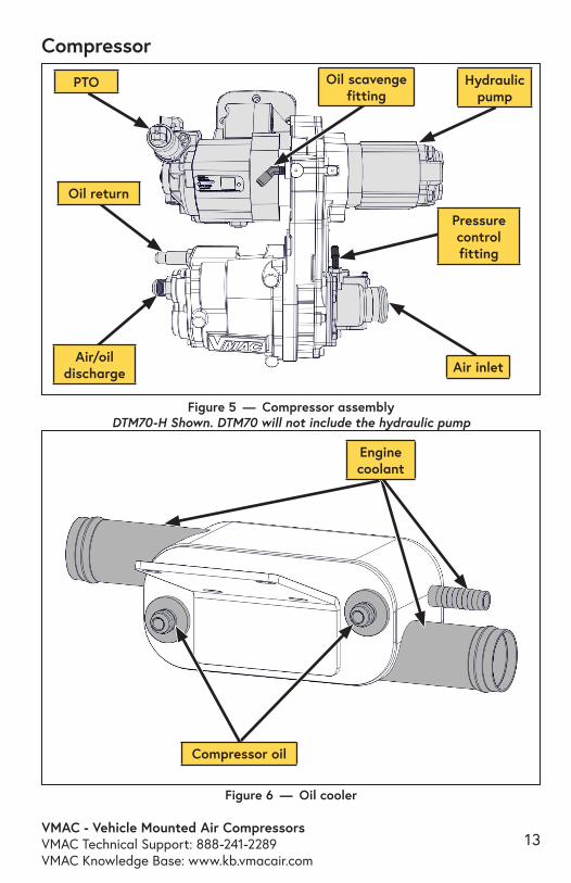
Compressor
Figure 5 — Compressor assembly DTM70-H Shown. DTM70 will not include the hydraulic pump
Air inlet
Oil return
Pressure control fitting
Air/oil discharge
Oil scavenge fitting
PTO Hydraulic pump
Figure 6 — Oil cooler
Engine coolant
Compressor oil

VMAC - Vehicle Mounted Air CompressorsVMAC Technical Support: 888-241-2289
VMAC Knowledge Base: www.kb.vmacair.com14
Throttle Control (DTM70)The Throttle Control responds to signals from the pressure sensor and commands the vehicle’s throttle to increase or decrease engine speed in response to air demand. The Throttle Control also allows the operator to configure the vehicle’s engine speed (when air is demanded) to their needs (maximum cfm, specific tool requirements, fuel efficiency, or a combination of these factors).
Figure 7 — DTM70 Variable Speed Throttle Control
“MAX RPM” and “IDLE DOWN PRESSURE”
adjusting screws(under side)
Hoses / TubesThe hoses used in VMAC compressor systems have an AQP inner liner that is compatible with VMAC compressor oil. The PTFE tubes used in VMAC systems are rated for the high temperatures VMAC compressors generate. Use of hoses or tubes other than those supplied or recommended by VMAC may cause compressor damage and may void your warranty. Please contact VMAC for replacement hoses/tubes or for further information.
• Hoses must have an AQP liner.
• Oil scavenge tubes must be PTFE.
• The black air brake tube is only suitable for use in the remote pressure control.
VMAC Compressor oil will degrade rubber lined hoses, use only hoses with an AQP elastomer type liner. Contact VMAC Technical Support at 1-888-241-2289 for further information.
VMAC - Vehicle Mounted Air CompressorsVMAC Technical Support: 888-241-2289VMAC Knowledge Base: www.kb.vmacair.com
15
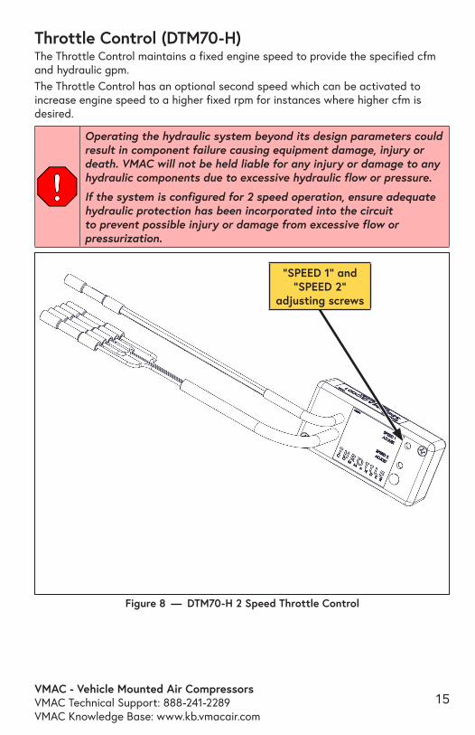
“SPEED 1” and “SPEED 2”
adjusting screws
Figure 8 — DTM70-H 2 Speed Throttle Control
Throttle Control (DTM70-H)The Throttle Control maintains a fixed engine speed to provide the specified cfm and hydraulic gpm. The Throttle Control has an optional second speed which can be activated to increase engine speed to a higher fixed rpm for instances where higher cfm is desired.
Operating the hydraulic system beyond its design parameters could result in component failure causing equipment damage, injury or death. VMAC will not be held liable for any injury or damage to any hydraulic components due to excessive hydraulic flow or pressure.
If the system is configured for 2 speed operation, ensure adequate hydraulic protection has been incorporated into the circuit to prevent possible injury or damage from excessive flow or pressurization.
VMAC - Vehicle Mounted Air CompressorsVMAC Technical Support: 888-241-2289
VMAC Knowledge Base: www.kb.vmacair.com16
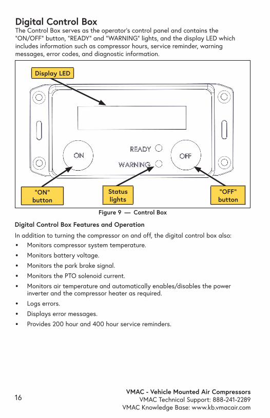
Digital Control BoxThe Control Box serves as the operator’s control panel and contains the “ON/OFF” button, “READY” and “WARNING” lights, and the display LED which includes information such as compressor hours, service reminder, warning messages, error codes, and diagnostic information.
Figure 9 — Control Box
Display LED
”ON” button
Status lights
”OFF” button
Digital Control Box Features and Operation
In addition to turning the compressor on and off, the digital control box also:
• Monitors compressor system temperature.
• Monitors battery voltage.
• Monitors the park brake signal.
• Monitors the PTO solenoid current.
• Monitors air temperature and automatically enables/disables the power inverter and the compressor heater as required.
• Logs errors.
• Displays error messages.
• Provides 200 hour and 400 hour service reminders.
VMAC - Vehicle Mounted Air CompressorsVMAC Technical Support: 888-241-2289VMAC Knowledge Base: www.kb.vmacair.com
17
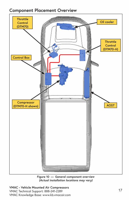
Component Placement Overview
Figure 10 — General component overview (Actual installation locations may vary)
Compressor (DTM70-H shown)
Control Box
Throttle Control
(DTM70-H)
AOST
Throttle Control (DTM70)
Oil cooler
VMAC - Vehicle Mounted Air CompressorsVMAC Technical Support: 888-241-2289
VMAC Knowledge Base: www.kb.vmacair.com18
Operating PrinciplesAir CompressionAt the heart of VMAC’s Transmission Mounted Air Compressor systems is a flooded lobe, rotary screw compressor. Compression occurs when filtered air, at normal atmospheric pressure, enters the chamber where it is trapped between meshing rotor lobes. Cooled oil is injected into the compressor housing during compression to seal the rotor lobes for maximum compression efficiency. The oil also lubricates the rotors and bearings and absorbs some of the heat generated during compression. As the rotors rotate, the meshing lobes compress the volume of air before sending the air/oil mixture down the discharge hose to be separated and cooled by the AOST.
Oil Separation and CoolingThe system uses a proprietary 2 stage air/oil separator. The hot air/oil mixture from the compressor enters the first stage of the AOST and is mechanically separated with baffles. The second stage uses an integral coalescing element to remove the remainder of the oil from the air stream. The hot compressor oil is directed to VMAC’s liquid to liquid cooler (which is tied into the vehicle’s engine coolant system) before being returned to the compressor.The small amount of oil recovered from the coalescing filter is returned directly to the compressor via the 1/4 in PTFE scavenge tube.
FiltrationVMAC rotary screw compressors are designed and machined to exacting standards. Foreign particles entering the compressor can damage components such as rotors, bearings, seals, and the housing resulting in performance, efficiency loss, and reduced system life. The system is equipped with a replaceable paper element air filter, a high pressure spin-on oil filter, scavenge screen and a coalescing filter in the back of the AOST.
Pressure Regulation and Engine Speed ControlWhen shut down, the VMAC system “blows down” or discharges all air stored in the AOST. When the system is started, the PTO engages and signals the Throttle Control to increase engine speed. Once the system has built to full system pressure (150 psi/1030 kPa), the pressure regulator signals the inlet to close. On DTM70 systems, the engine speed will reduce to base idle; DTM70-H systems will remain at elevated engine speed to maintain hydraulic pressure and flow. The mechanical pressure regulator detects air use and will send a signal to the open the inlet. On DTM70 systems, engine speed will increase once a 10 psi drop in pressure is detected. The VMAC control system offers the following benefits:• Reduced fuel consumption when not using air (DTM70 only).• Reduced load on the compressor cooling system.• Reduced noise when not using air (DTM70 only).• Quick response to airflow demands.
VMAC - Vehicle Mounted Air CompressorsVMAC Technical Support: 888-241-2289VMAC Knowledge Base: www.kb.vmacair.com
19
The elevated engine speed, and maximum pressure are adjustable. Higher engine speeds will yield higher compressor output (cfm) and hydraulic flow (gpm) but will generate more noise and consume more fuel. See the “Performance Testing and System Adjustments” chapter on page 48 for instructions.
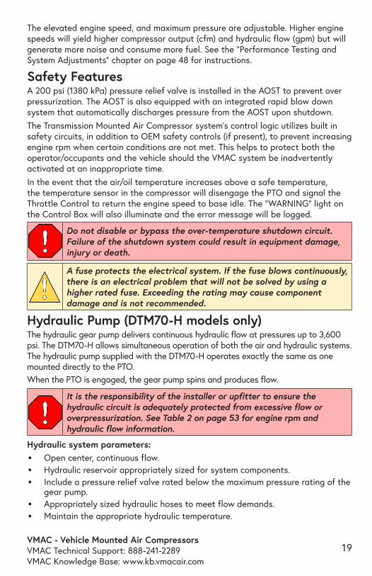
Safety FeaturesA 200 psi (1380 kPa) pressure relief valve is installed in the AOST to prevent over pressurization. The AOST is also equipped with an integrated rapid blow down system that automatically discharges pressure from the AOST upon shutdown.The Transmission Mounted Air Compressor system’s control logic utilizes built in safety circuits, in addition to OEM safety controls (if present), to prevent increasing engine rpm when certain conditions are not met. This helps to protect both the operator/occupants and the vehicle should the VMAC system be inadvertently activated at an inappropriate time. In the event that the air/oil temperature increases above a safe temperature, the temperature sensor in the compressor will disengage the PTO and signal the Throttle Control to return the engine speed to base idle. The “WARNING” light on the Control Box will also illuminate and the error message will be logged.
A fuse protects the electrical system. If the fuse blows continuously, there is an electrical problem that will not be solved by using a higher rated fuse. Exceeding the rating may cause component damage and is not recommended.
Do not disable or bypass the over-temperature shutdown circuit. Failure of the shutdown system could result in equipment damage, injury or death.
Hydraulic Pump (DTM70-H models only)The hydraulic gear pump delivers continuous hydraulic flow at pressures up to 3,600 psi. The DTM70-H allows simultaneous operation of both the air and hydraulic systems. The hydraulic pump supplied with the DTM70-H operates exactly the same as one mounted directly to the PTO. When the PTO is engaged, the gear pump spins and produces flow.
Hydraulic system parameters:• Open center, continuous flow.• Hydraulic reservoir appropriately sized for system components.• Include a pressure relief valve rated below the maximum pressure rating of the
gear pump.• Appropriately sized hydraulic hoses to meet flow demands.• Maintain the appropriate hydraulic temperature.
It is the responsibility of the installer or upfitter to ensure the hydraulic circuit is adequately protected from excessive flow or overpressurization. See Table 2 on page 53 for engine rpm and hydraulic flow information.
VMAC - Vehicle Mounted Air CompressorsVMAC Technical Support: 888-241-2289
VMAC Knowledge Base: www.kb.vmacair.com20
Upfitter Vehicle Controls
The following steps are only applicable to vehicles equipped with third party vehicle control systems (such those included with hydraulic cranes).On vehicles with additional control systems (such as crane remotes), the DTM70-H can be activated/deactivated remotely much like a standard PTO using these controls.Control systems which include a high/low speed function (High Idle) can also be configured to toggle the VMAC Throttle Control between high and low rpm settings.
This section is intended as a general guideline. Refer to the third party vehicle control manufacturer’s documentation for specific installation instructions.
All third party vehicle control systems intended to activate the PTO system must do so via the VMAC Control Box. Refer to the electrical schematic on page 36.
It is the responsibility of the installer or upfitter to ensure that third party vehicle control systems are not able to affect engine speed while the PTO system is in use. Any change to engine speed while the PTO system is activated could cause component damage or unexpected hydraulic circuit function (e.g. unpredictable crane control) which could result in injury or death.
VMAC - Vehicle Mounted Air CompressorsVMAC Technical Support: 888-241-2289VMAC Knowledge Base: www.kb.vmacair.com
21
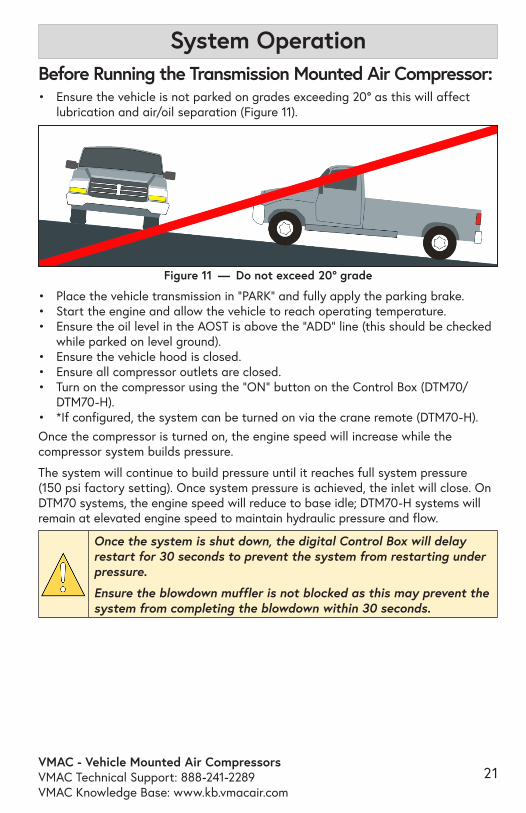
System OperationBefore Running the Transmission Mounted Air Compressor:• Ensure the vehicle is not parked on grades exceeding 20° as this will affect
lubrication and air/oil separation (Figure 11).
Once the system is shut down, the digital Control Box will delay restart for 30 seconds to prevent the system from restarting under pressure.
Ensure the blowdown muffler is not blocked as this may prevent the system from completing the blowdown within 30 seconds.
• Place the vehicle transmission in “PARK” and fully apply the parking brake.• Start the engine and allow the vehicle to reach operating temperature.• Ensure the oil level in the AOST is above the “ADD” line (this should be checked
while parked on level ground).• Ensure the vehicle hood is closed. • Ensure all compressor outlets are closed.• Turn on the compressor using the “ON” button on the Control Box (DTM70/
DTM70-H).• *If configured, the system can be turned on via the crane remote (DTM70-H).Once the compressor is turned on, the engine speed will increase while the compressor system builds pressure.
The system will continue to build pressure until it reaches full system pressure (150 psi factory setting). Once system pressure is achieved, the inlet will close. On DTM70 systems, the engine speed will reduce to base idle; DTM70-H systems will remain at elevated engine speed to maintain hydraulic pressure and flow.
Figure 11 — Do not exceed 20° grade
VMAC - Vehicle Mounted Air CompressorsVMAC Technical Support: 888-241-2289
VMAC Knowledge Base: www.kb.vmacair.com22
Diesel Particulate Filter (DPF) WarningWhen engine driven, or PTO driven equipment is run on vehicles with a DPF for extended periods of time, particulates may build up in the filter. All vehicles with a DPF have a warning light on the instrument panel or notification in the message center.
It is impossible to make recommendations regarding run time before the DPF system will require a “regeneration” cycle as this is affected by many variables. It is therefore the responsibility of the operator to monitor and take the necessary action to maintain the DPF system.
It is suggested that if equipment is run for extended periods of time (over 1 hour) without driving, the vehicle DPF warning system is checked after 1 hour and every 15 min thereafter. If the DPF warning light/message appears, refer to the vehicle owner’s manual for methods of cleaning or regenerating.
To prevent engine damage, the Engine Control Module (ECM) will deactivate the SEIC system if any of the vehicle’s parameters fall outside of normal operating specification.
Cold Environment OperationDTM70 systems include a heater cartridge installed in the compressor. When the vehicle ignition switch is on, the system monitors compressor temperature and will automatically enable the heater cartridge when it detects that the compressor temperature is below -10 °C (14 °F). If operating the system in temperatures below -10 °C (14 °F), ensure the following conditions are met prior to starting the system: • Allow the vehicle to reach operating temperature.• Turn on the compressor system and operate as normal.
Ford Stationary Elevated Idle Control (SEIC) Restart Delay (DTM70-H)
On vehicles that are consistently used in cold climates, the VMAC De-Icer Kit (VMAC P/N: A700031) is recommended. The VMAC De-Icer Kit is installed on the pressure control PTFE tube and is independent of the included compressor heater.
OEM programming for the SEIC system maintains elevated idle for approximately 2.5 seconds after the high idle request is removed.
If air is requested during this time, the SEIC system will not recognize the high idle request. Should this occur, turn off the compressor system via the button on the Control Box. Once the 30 second restart delay countdown has completed, turn the compressor system on and the system should operate normally.
VMAC - Vehicle Mounted Air CompressorsVMAC Technical Support: 888-241-2289VMAC Knowledge Base: www.kb.vmacair.com
23
Routine Maintenance In order to maintain the VMAC warranty, VMAC’s maintenance schedule must be followed. Only genuine VMAC parts can be used to maintain the system.
With proper maintenance, the likelihood of premature failure or component replacement can be drastically reduced.
The most critical aspect of maintenance is proper air filtration and clean oil. If any particles enter the compressor, they can score the rotors and contaminate the roller bearings in the compressor. Any contamination will cause rapid and severe damage to components.
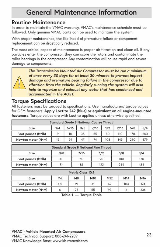
The Transmission Mounted Air Compressor must be run a minimum of once every 30 days for at least 30 minutes to prevent impact damage and premature bearing failure in the compressor due to vibration from the vehicle. Regularly running the system will also help to vaporize and exhaust any water that has condensed and accumulated in the AOST.
Torque SpecificationsAll fasteners must be torqued to specifications. Use manufacturers’ torque values for OEM fasteners. Apply Loctite 242 (blue) or equivalent on all engine-mounted fasteners. Torque values are with Loctite applied unless otherwise specified.
Table 1 — Torque Table
Standard Grade 8 National Coarse Thread
Size 1/4 5/16 3/8 7/16 1/2 9/16 5/8 3/4
Foot pounds (ft•lb) 9 18 35 55 80 110 170 280
Newton meter (N•m) 12 24 47 74 108 149 230 379
Standard Grade 8 National Fine Thread
Size 3/8 7/16 1/2 5/8 3/4
Foot pounds (ft•lb) 40 60 90 180 320
Newton meter (N•m) 54 81 122 244 434
Metric Class 10.9
Size M6 M8 M10 M12 M14 M16
Foot pounds (ft•lb) 4.5 19 41 69 104 174
Newton meter (N•m) 6 25 55 93 141 236
General Maintenance Information

VMAC - Vehicle Mounted Air CompressorsVMAC Technical Support: 888-241-2289
VMAC Knowledge Base: www.kb.vmacair.com24
Installation Manuals and Illustrated Parts Lists (IPL)The installation manual and illustrated parts list are an invaluable resource for when inspecting, diagnosing or repairing the system. The installation manuals and IPL’s are available free of charge from VMAC.
VMAC Installation Manualshttps://www.vmacair.com/support/manuals/
VMAC IPLshttps://www.vmacair.com/support/ipl/
VMAC - Vehicle Mounted Air CompressorsVMAC Technical Support: 888-241-2289VMAC Knowledge Base: www.kb.vmacair.com
25
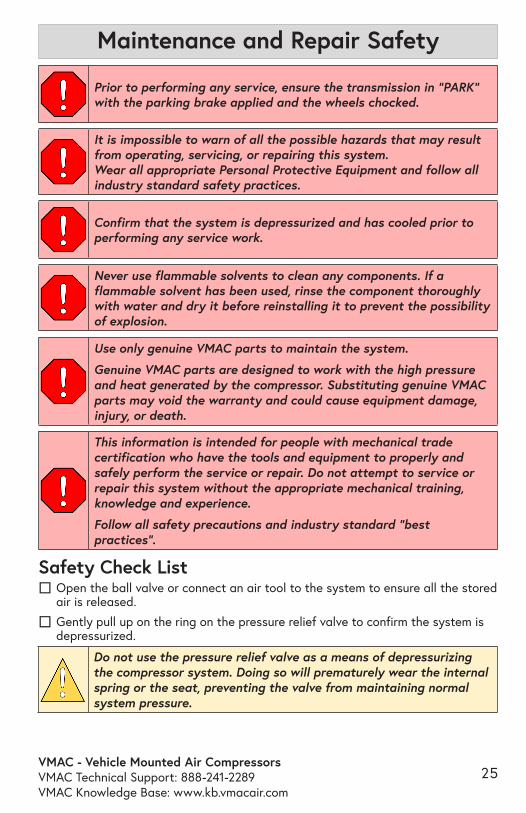
It is impossible to warn of all the possible hazards that may result from operating, servicing, or repairing this system. Wear all appropriate Personal Protective Equipment and follow all industry standard safety practices.
Confirm that the system is depressurized and has cooled prior to performing any service work.
Never use flammable solvents to clean any components. If a flammable solvent has been used, rinse the component thoroughly with water and dry it before reinstalling it to prevent the possibility of explosion.
This information is intended for people with mechanical trade certification who have the tools and equipment to properly and safely perform the service or repair. Do not attempt to service or repair this system without the appropriate mechanical training, knowledge and experience.
Follow all safety precautions and industry standard “best practices”.
Maintenance and Repair Safety
Safety Check List ☐ Open the ball valve or connect an air tool to the system to ensure all the stored air is released.
☐ Gently pull up on the ring on the pressure relief valve to confirm the system is depressurized.
Do not use the pressure relief valve as a means of depressurizing the compressor system. Doing so will prematurely wear the internal spring or the seat, preventing the valve from maintaining normal system pressure.
Use only genuine VMAC parts to maintain the system.
Genuine VMAC parts are designed to work with the high pressure and heat generated by the compressor. Substituting genuine VMAC parts may void the warranty and could cause equipment damage, injury, or death.
Prior to performing any service, ensure the transmission in “PARK” with the parking brake applied and the wheels chocked.
VMAC - Vehicle Mounted Air CompressorsVMAC Technical Support: 888-241-2289
VMAC Knowledge Base: www.kb.vmacair.com26
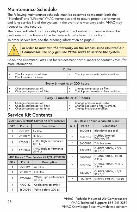
Maintenance ScheduleThe following maintenance schedule must be observed to maintain both the “Standard” and “Lifetime” VMAC warranties and to assure proper performance and long service life of the system. In the event of a warranty claim, VMAC may request service records. The hours indicated are those displayed on the Control Box. Service should be performed at the lesser of the two intervals (whichever occurs first). To order service kits, see the ordering information on page 3.
In order to maintain the warranty on the Transmission Mounted Air Compressor, use only genuine VMAC parts to service the system.
Check the Illustrated Parts List for replacement part numbers or contact VMAC for more information.
Every 6 months or 200 hours
Every 12 months or 400 hours• Change compressor oil.• Change compressor oil filter.• Change compressor air filter.
• Change pressure relief valve.• Change coalescing filter element.• Change blowdown muffler.
• Change compressor oil.• Change compressor oil filter.
• Change compressor air filter.• Check pressure relief valve condition.
Daily• Check compressor oil level.• Check system for leaks.
• Check pressure relief valve condition.
400 Hour / 1 Year Service Kit P/N: A700230
QTY Part # Description
1 9500061 Air filter
1 9200039 Oil filter
1 A700094 VMAC High performance oil (4 L)
1 A700152 Coalescing assembly
1 3600054 Valve, safety, 200 psi
200 Hour / 6 Month Service Kit P/N: A700229
QTY Part # Description
1 9500061 Air filter
1 9200039 Oil filter
2 A700091 VMAC High performance oil (1 L)
1 A700094 VMAC High performance oil (4 L)
Service Kit Contents
1 3600064 Blowdown cap seal
1 4500104 Muffler, Sintered Exhaust, 1/8
1 3600090 Thimble scree
1 5830066 O-RING, VITON, 4 3/4 ID X 1/8
1 5830080 O-RING, VITON, 1/4 ID X 1/16
1 5830106 O-RING, VITON, 7/16 ID X 1/16
1 5830007 O-RING, VITON, 4 1/2 ID X 1/8
1 5840069 SPRING, COMPRESSION
400 Hour / 1 Year Service Kit (Cont.)
QTY Part # Description
VMAC - Vehicle Mounted Air CompressorsVMAC Technical Support: 888-241-2289VMAC Knowledge Base: www.kb.vmacair.com
27
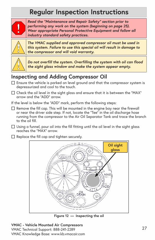
Read the “Maintenance and Repair Safety” section prior to performing any work on the system (beginning on page 25).Wear appropriate Personal Protective Equipment and follow all industry standard safety practices.
The VMAC supplied and approved compressor oil must be used in this system. Failure to use this special oil will result in damage to the compressor and will void warranty.
Inspecting and Adding Compressor Oil ☐ Ensure the vehicle is parked on level ground and that the compressor system is depressurized and cool to the touch.
☐ Check the oil level in the sight glass and ensure that it is between the “MAX” arrow and the “ADD” arrow.
If the level is below the “ADD” mark, perform the following steps:
☐ Remove the fill cap. This will be mounted in the engine bay near the firewall or near the driver side step. If not, locate the “Tee” in the oil discharge hose running from the compressor to the Air Oil Separator Tank and trace the branch to the oil fill.
☐ Using a funnel, pour oil into the fill fitting until the oil level in the sight glass reaches the “MAX” arrow.
☐ Replace the fill cap and tighten securely.
Figure 12 — Inspecting the oil
Regular Inspection Instructions
Do not overfill the system. Overfilling the system with oil can flood the sight glass window and make the system appear empty.
Oil sight glass

VMAC - Vehicle Mounted Air CompressorsVMAC Technical Support: 888-241-2289
VMAC Knowledge Base: www.kb.vmacair.com28
Inspecting and Replacing the Blowdown MufflerRead the “Maintenance and Repair Safety” section prior to performing any work on the system (beginning on page 25).Wear appropriate Personal Protective Equipment and follow all industry standard safety practices.
The Blowdown Muffler (or remote blowdown muffler) is a regular service item and must be replaced every 400 hours or 1 year, whichever interval occurs first.
Visually inspect the blowdown muffler for evidence of corrosion or loss of functionality. Ensure the muffler allows the system to depressurize. To test the blowdown system and muffler:
☐ Turn the system on and allow it reach full system pressure (factory setting 150 psi).
☐ Turn off the system.
☐ Listen for the pressurized air to blowdown through the muffler on the AOST. Blowdown should be completed in approximately 20 seconds.
☐ If the muffler is showing signs of blockage, contact a local VMAC dealer for a replacement.
A replacement blowdown muffler is included with the VMAC 400 hour service kit.
Figure 13 — Blowdown muffler
Blowdown muffler
VMAC - Vehicle Mounted Air CompressorsVMAC Technical Support: 888-241-2289VMAC Knowledge Base: www.kb.vmacair.com
29
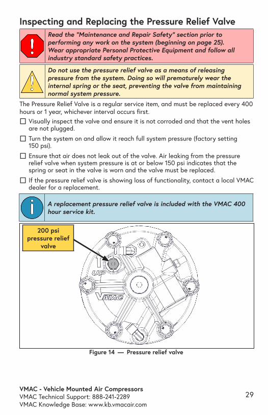
Inspecting and Replacing the Pressure Relief ValveRead the “Maintenance and Repair Safety” section prior to performing any work on the system (beginning on page 25).Wear appropriate Personal Protective Equipment and follow all industry standard safety practices.
Do not use the pressure relief valve as a means of releasing pressure from the system. Doing so will prematurely wear the internal spring or the seat, preventing the valve from maintaining normal system pressure.
A replacement pressure relief valve is included with the VMAC 400 hour service kit.
Figure 14 — Pressure relief valve
200 psi pressure relief
valve
The Pressure Relief Valve is a regular service item, and must be replaced every 400 hours or 1 year, whichever interval occurs first.
☐ Visually inspect the valve and ensure it is not corroded and that the vent holes are not plugged.
☐ Turn the system on and allow it reach full system pressure (factory setting 150 psi).
☐ Ensure that air does not leak out of the valve. Air leaking from the pressure relief valve when system pressure is at or below 150 psi indicates that the spring or seat in the valve is worn and the valve must be replaced.
☐ If the pressure relief valve is showing loss of functionality, contact a local VMAC dealer for a replacement.
VMAC - Vehicle Mounted Air CompressorsVMAC Technical Support: 888-241-2289
VMAC Knowledge Base: www.kb.vmacair.com30
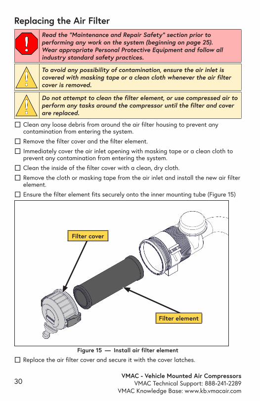
Replacing the Air Filter
To avoid any possibility of contamination, ensure the air inlet is covered with masking tape or a clean cloth whenever the air filter cover is removed.
Read the “Maintenance and Repair Safety” section prior to performing any work on the system (beginning on page 25).Wear appropriate Personal Protective Equipment and follow all industry standard safety practices.
☐ Clean any loose debris from around the air filter housing to prevent any contamination from entering the system.
☐ Remove the filter cover and the filter element.
☐ Immediately cover the air inlet opening with masking tape or a clean cloth to prevent any contamination from entering the system.
☐ Clean the inside of the filter cover with a clean, dry cloth.
☐ Remove the cloth or masking tape from the air inlet and install the new air filter element.
☐ Ensure the filter element fits securely onto the inner mounting tube (Figure 15)
Do not attempt to clean the filter element, or use compressed air to perform any tasks around the compressor until the filter and cover are replaced.
☐ Replace the air filter cover and secure it with the cover latches. Figure 15 — Install air filter element
Filter cover
Filter element
VMAC - Vehicle Mounted Air CompressorsVMAC Technical Support: 888-241-2289VMAC Knowledge Base: www.kb.vmacair.com
31
Read the “Maintenance and Repair Safety” section prior to performing any work on the system (beginning on page 25).Wear appropriate Personal Protective Equipment and follow all industry standard safety practices.
Do not use compressed air or perform any other tasks around the air filter and cover until both are replaced. Never clean the filter element with compressed air as this may allow contaminants to enter the compressor system. Always replace the air filter element during this service.
Do not overfill the system. Overfilling the system with oil can flood the sight glass window and make the system appear empty.
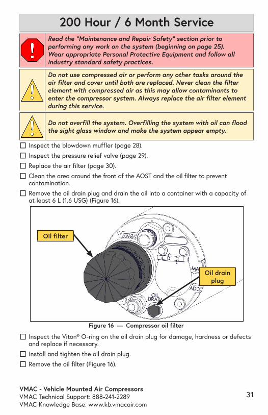
☐ Inspect the blowdown muffler (page 28).
☐ Inspect the pressure relief valve (page 29).
☐ Replace the air filter (page 30).
☐ Clean the area around the front of the AOST and the oil filter to prevent contamination.
☐ Remove the oil drain plug and drain the oil into a container with a capacity of at least 6 L (1.6 USG) (Figure 16).
☐ Inspect the Viton® O-ring on the oil drain plug for damage, hardness or defects and replace if necessary.
☐ Install and tighten the oil drain plug.
☐ Remove the oil filter (Figure 16).
Figure 16 — Compressor oil filter
200 Hour / 6 Month Service
Oil drain plug
Oil filter
VMAC - Vehicle Mounted Air CompressorsVMAC Technical Support: 888-241-2289
VMAC Knowledge Base: www.kb.vmacair.com32
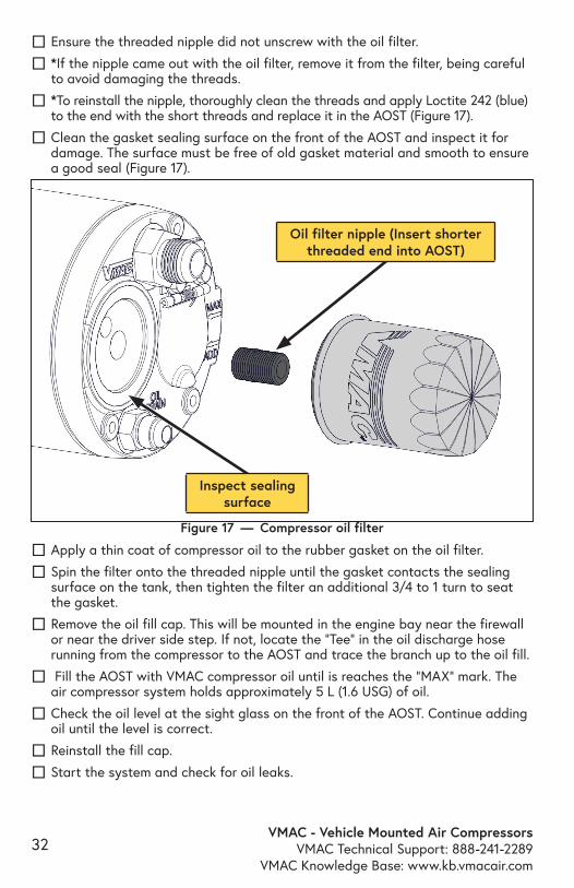
☐ Ensure the threaded nipple did not unscrew with the oil filter.
☐ *If the nipple came out with the oil filter, remove it from the filter, being careful to avoid damaging the threads.
☐ *To reinstall the nipple, thoroughly clean the threads and apply Loctite 242 (blue) to the end with the short threads and replace it in the AOST (Figure 17).
☐ Clean the gasket sealing surface on the front of the AOST and inspect it for damage. The surface must be free of old gasket material and smooth to ensure a good seal (Figure 17).
Figure 17 — Compressor oil filter
Inspect sealing surface
Oil filter nipple (Insert shorter threaded end into AOST)
☐ Apply a thin coat of compressor oil to the rubber gasket on the oil filter.
☐ Spin the filter onto the threaded nipple until the gasket contacts the sealing surface on the tank, then tighten the filter an additional 3/4 to 1 turn to seat the gasket.
☐ Remove the oil fill cap. This will be mounted in the engine bay near the firewall or near the driver side step. If not, locate the “Tee” in the oil discharge hose running from the compressor to the AOST and trace the branch up to the oil fill.
☐ Fill the AOST with VMAC compressor oil until is reaches the “MAX” mark. The air compressor system holds approximately 5 L (1.6 USG) of oil.
☐ Check the oil level at the sight glass on the front of the AOST. Continue adding oil until the level is correct.
☐ Reinstall the fill cap.
☐ Start the system and check for oil leaks.
VMAC - Vehicle Mounted Air CompressorsVMAC Technical Support: 888-241-2289VMAC Knowledge Base: www.kb.vmacair.com
33
☐ Allow the system to build to full system pressure (factory setting 150 psi) (on DTM70 systems, allow the engine speed to decrease to base idle).
☐ Turn the system “OFF”.
☐ Once the system has sat for 5 minutes, check the oil level through the sight glass and add oil as necessary.
☐ Verify there are no oil leaks.
Clearing Service Reminders ☐ For systems that show a message “HRSxxx200HRSVC” or “HRSxxx400HRSVC” on the control box:
• Press and hold the “OFF” button for approximately 5 seconds until “DIAGNOSTICS” appears on the display.
• Press and hold the “OFF” button (approximately 5 seconds) until “200 HR CLEAR” appears in the display.
• Continue holding the “OFF” button until “CLEAR OK” appears in the display.

VMAC - Vehicle Mounted Air CompressorsVMAC Technical Support: 888-241-2289
VMAC Knowledge Base: www.kb.vmacair.com34
Read the “Maintenance and Repair Safety” section prior to performing any work on the system (beginning on page 25.Wear appropriate Personal Protective Equipment and follow all industry standard safety practices.
Do not use compressed air or perform any other tasks around the air filter and cover until both are replaced. Never clean the filter element with compressed air as this may allow contaminates to enter the compressor system. Always replace the air filter element during this service.
Do not overfill the system. Overfilling the system with oil can flood the sight glass window and make the system appear empty.
400 Hour / 1 year Service
☐ Apply thread sealant and replace the blowdown muffler (page 28).
☐ Apply thread sealant and replace the pressure relief valve (page 29).
☐ Replace the air filter (page 30).
☐ Clean the area around the AOST and the oil filter to prevent contamination.
☐ Remove the oil drain plug and drain the oil into a container with a capacity of at least 6 L (1.6 USG) (Figure 18).
☐ Inspect the Viton® O-ring on the oil drain plug for damage, hardness or defects and replace if necessary.
☐ Install and tighten the oil drain plug.
☐ Remove the oil filter (Figure 16).
Figure 18 — Compressor oil maintnance
Oil drain plug
Oil filter
VMAC - Vehicle Mounted Air CompressorsVMAC Technical Support: 888-241-2289VMAC Knowledge Base: www.kb.vmacair.com
35
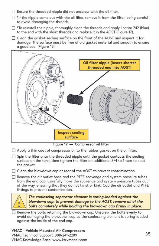
☐ Ensure the threaded nipple did not unscrew with the oil filter.
☐ *If the nipple came out with the oil filter, remove it from the filter, being careful to avoid damaging the threads.
☐ *To reinstall the nipple, thoroughly clean the threads and apply Loctite 242 (blue) to the end with the short threads and replace it in the AOST (Figure 17).
☐ Clean the gasket sealing surface on the front of the AOST and inspect it for damage. The surface must be free of old gasket material and smooth to ensure a good seal (Figure 19).
Figure 19 — Compressor oil filter
Inspect sealing surface
Oil filter nipple (Insert shorter threaded end into AOST)
☐ Apply a thin coat of compressor oil to the rubber gasket on the oil filter.
☐ Spin the filter onto the threaded nipple until the gasket contacts the sealing surface on the tank, then tighten the filter an additional 3/4 to 1 turn to seat the gasket.
☐ Clean the blowdown cap at rear of the AOST to prevent contamination.
☐ Remove the air outlet hose and the PTFE scavenge and system pressure tubes from the end cap. Carefully move the scavenge and system pressure tubes out of the way, ensuring that they do not twist or kink. Cap the air outlet and PTFE fittings to prevent contamination.
☐ Remove the bolts retaining the blowdown cap. Unscrew the bolts evenly to avoid damaging the blowdown cap as the coalescing element is spring-loaded against the inside of the end cap.
The coalescing separator element is spring-loaded against the blowdown cap; to prevent damage to the AOST, remove all of the bolts completely while holding the blowdown cap firmly in place.
VMAC - Vehicle Mounted Air CompressorsVMAC Technical Support: 888-241-2289
VMAC Knowledge Base: www.kb.vmacair.com36
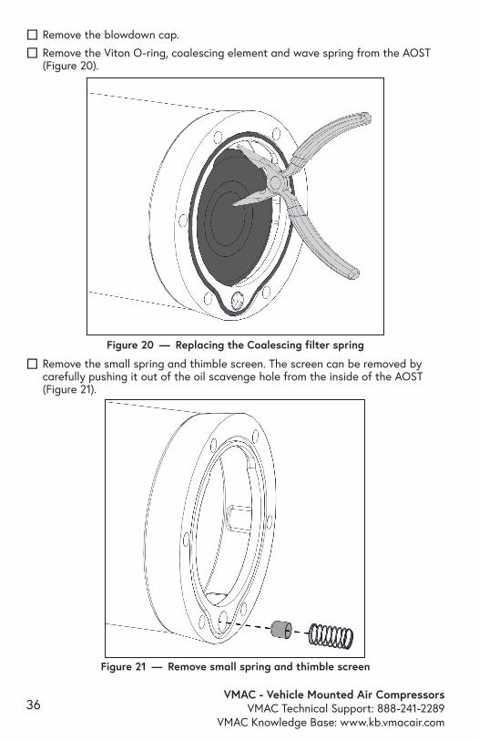
☐ Remove the blowdown cap.
☐ Remove the Viton O-ring, coalescing element and wave spring from the AOST (Figure 20).
☐ Remove the small spring and thimble screen. The screen can be removed by carefully pushing it out of the oil scavenge hole from the inside of the AOST (Figure 21).
Figure 20 — Replacing the Coalescing filter spring
Figure 21 — Remove small spring and thimble screen
VMAC - Vehicle Mounted Air CompressorsVMAC Technical Support: 888-241-2289VMAC Knowledge Base: www.kb.vmacair.com
37
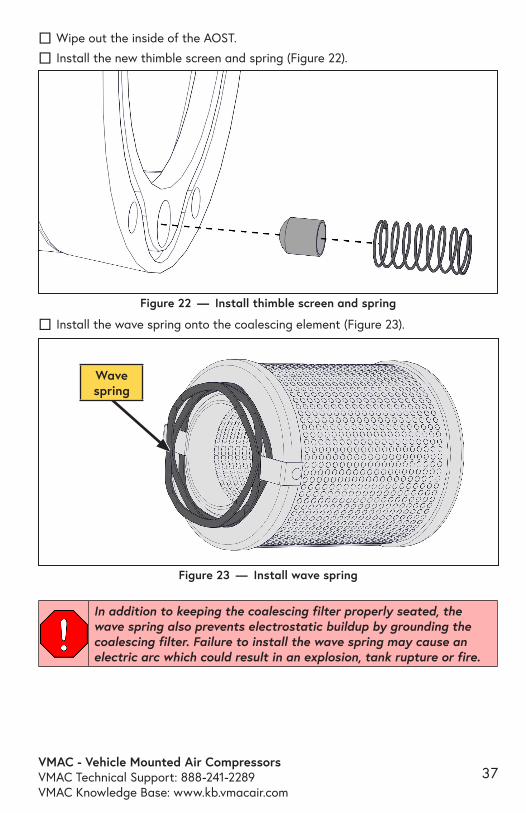
☐ Install the wave spring onto the coalescing element (Figure 23).
☐ Wipe out the inside of the AOST.
☐ Install the new thimble screen and spring (Figure 22).
Figure 22 — Install thimble screen and spring
Figure 23 — Install wave spring
In addition to keeping the coalescing filter properly seated, the wave spring also prevents electrostatic buildup by grounding the coalescing filter. Failure to install the wave spring may cause an electric arc which could result in an explosion, tank rupture or fire.
Wave spring
VMAC - Vehicle Mounted Air CompressorsVMAC Technical Support: 888-241-2289
VMAC Knowledge Base: www.kb.vmacair.com38
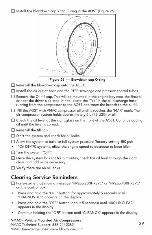
☐ Install the Blowdown cap seal in the blowdown cap (Figure 25).
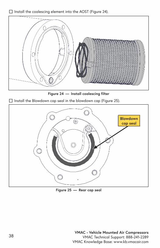
Figure 24 — Install coalescing filter
Blowdown cap seal
☐ Install the coalescing element into the AOST (Figure 24).
Figure 25 — Rear cap seal
VMAC - Vehicle Mounted Air CompressorsVMAC Technical Support: 888-241-2289VMAC Knowledge Base: www.kb.vmacair.com
39
☐ Install the blowdown cap Viton O-ring in the AOST (Figure 26).
Figure 26 — Blowdown cap O-ring
☐ Reinstall the blowdown cap onto the AOST.
☐ Install the air outlet hose and the PTFE scavenge and pressure control tubes.
☐ Remove the Oil fill cap. This will be mounted in the engine bay near the firewall or near the driver side step. If not, locate the “Tee” in the oil discharge hose running from the compressor to the AOST and trace the branch to the oil fill.
☐ Fill the AOST with VMAC compressor oil until is reaches the “MAX” mark. The air compressor system holds approximately 5 L (1.6 USG) of oil.
☐ Check the oil level at the sight glass on the front of the AOST. Continue adding oil until the level is correct.
☐ Reinstall the fill cap.
☐ Start the system and check for oil leaks.
☐ Allow the system to build to full system pressure (factory setting 150 psi).• *On DTM70 systems, allow the engine speed to decrease to base idle).
☐ Turn the system “OFF”.
☐ Once the system has sat for 5 minutes, check the oil level through the sight glass and add oil as necessary.
☐ Verify there are no oil leaks.
Clearing Service Reminders ☐ For systems that show a message “HRSxxx200HRSVC” or “HRSxxx400HRSVC” on the control box:
• Press and hold the “OFF” button for approximately 5 seconds until “DIAGNOSTICS” appears on the display.
• Press and hold the “OFF” button (about 5 seconds) until “400 HR CLEAR” appears in the display.
• Continue holding the “OFF” button until “CLEAR OK” appears in the display.
VMAC - Vehicle Mounted Air CompressorsVMAC Technical Support: 888-241-2289
VMAC Knowledge Base: www.kb.vmacair.com40
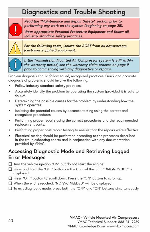
Read the “Maintenance and Repair Safety” section prior to performing any work on the system (beginning on page 25).
Wear appropriate Personal Protective Equipment and follow all industry standard safety practices.
For the following tests, isolate the AOST from all downstream (customer supplied) equipment.
If the Transmission Mounted Air Compressor system is still within the warranty period, see the warranty claim process on page 9 prior to commencing with any diagnostics or repairs.
Problem diagnosis should follow sound, recognized practices. Quick and accurate diagnosis of problems should involve the following:
• Follow industry standard safety practices.
• Accurately identify the problem by operating the system (provided it is safe to do so).
• Determining the possible causes for the problem by understanding how the system operates.
• Isolating the potential causes by accurate testing using the correct and recognized procedures.
• Performing proper repairs using the correct procedures and the recommended replacement parts.
• Performing proper post repair testing to ensure that the repairs were effective.
• Electrical testing should be performed according to the processes described in the troubleshooting charts and in conjunction with any documentation provided by VMAC.
Accessing Diagnostic Mode and Retrieving Logged Error Messages
☐ Turn the vehicle ignition “ON” but do not start the engine. ☐ Press and hold the “OFF“ button on the Control Box until “DIAGNOSTICS” is displayed.
☐ Press “OFF” button to scroll down. Press the “ON” button to scroll up. ☐ When the end is reached, “NO SVC NEEDED” will be displayed. ☐ To exit diagnostic mode, press both the “OFF” and “ON” buttons simultaneously.
Diagnostics and Trouble Shooting
VMAC - Vehicle Mounted Air CompressorsVMAC Technical Support: 888-241-2289VMAC Knowledge Base: www.kb.vmacair.com
41
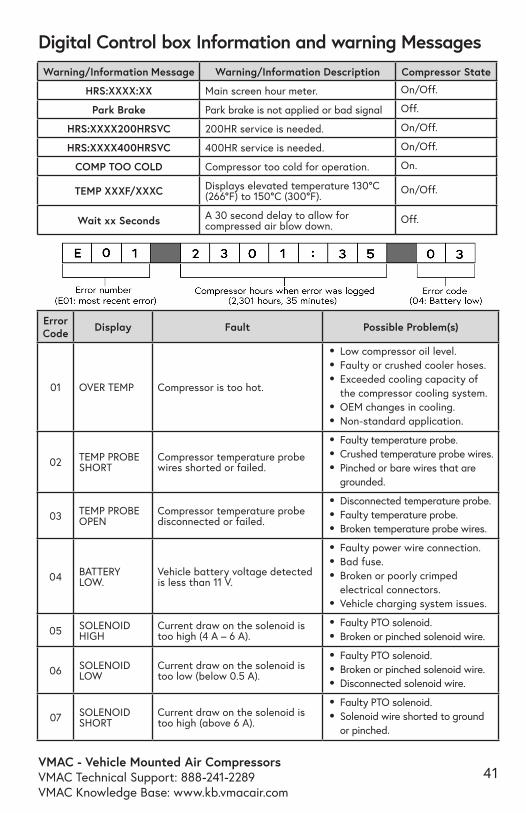
Error Code Display Fault Possible Problem(s)
01 OVER TEMP Compressor is too hot.
• Low compressor oil level. • Faulty or crushed cooler hoses. • Exceeded cooling capacity of
the compressor cooling system. • OEM changes in cooling.• Non-standard application.
02 TEMP PROBE SHORT
Compressor temperature probe wires shorted or failed.
• Faulty temperature probe. • Crushed temperature probe wires. • Pinched or bare wires that are
grounded.
03 TEMP PROBE OPEN
Compressor temperature probe disconnected or failed.
• Disconnected temperature probe. • Faulty temperature probe. • Broken temperature probe wires.
04 BATTERY LOW.
Vehicle battery voltage detected is less than 11 V.
• Faulty power wire connection.• Bad fuse.• Broken or poorly crimped
electrical connectors.• Vehicle charging system issues.
05 SOLENOID HIGH
Current draw on the solenoid is too high (4 A – 6 A).
• Faulty PTO solenoid. • Broken or pinched solenoid wire.
06 SOLENOID LOW
Current draw on the solenoid is too low (below 0.5 A).
• Faulty PTO solenoid. • Broken or pinched solenoid wire.• Disconnected solenoid wire.
07 SOLENOID SHORT
Current draw on the solenoid is too high (above 6 A).
• Faulty PTO solenoid. • Solenoid wire shorted to ground
or pinched.
Digital Control box Information and warning MessagesWarning/Information Message Warning/Information Description Compressor State
HRS:XXXX:XX Main screen hour meter. On/Off.
Park Brake Park brake is not applied or bad signal Off.
HRS:XXXX200HRSVC 200HR service is needed. On/Off.
HRS:XXXX400HRSVC 400HR service is needed. On/Off.
COMP TOO COLD Compressor too cold for operation. On.
TEMP XXXF/XXXC Displays elevated temperature 130°C (266°F) to 150°C (300°F).
On/Off.
Wait xx Seconds A 30 second delay to allow for compressed air blow down.
Off.
VMAC - Vehicle Mounted Air CompressorsVMAC Technical Support: 888-241-2289
VMAC Knowledge Base: www.kb.vmacair.com42
Symptom Possible Cause Corrective Action
Compressor does not run.
Oil temperature too high. Turn compressor off, allow to cool for 30 minutes, retry.
Oil level too low. Add oil as necessary. See page 27.
No power to PTO solenoid. • Repair wiring according to
diagram.• Check/replace fuse.
Poor PTO solenoid ground.Check the ground connection from the PTO solenoid for breaks and repair as necessary.
Faulty PTO solenoid.
With the compressor button “OFF” and the PTO wire disconnected, check the resistance between the 2 pins on the solenoid. Resistance should be between 6 Ω – 9 Ω at 25 °C (77 °F). If outside of this range, replace the solenoid.
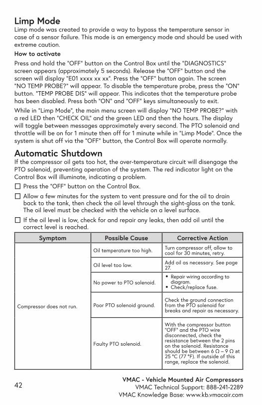
Limp ModeLimp mode was created to provide a way to bypass the temperature sensor in case of a sensor failure. This mode is an emergency mode and should be used with extreme caution.How to activatePress and hold the “OFF” button on the Control Box until the “DIAGNOSTICS” screen appears (approximately 5 seconds). Release the “OFF” button and the screen will display “E01 xxxx xx xx”. Press the “OFF” button again. The screen “NO TEMP PROBE?“ will appear. To disable the temperature probe, press the “ON” button. “TEMP PROBE DIS” will appear. This indicates that the temperature probe has been disabled. Press both “ON” and “OFF” keys simultaneously to exit.While in “Limp Mode”, the main menu screen will display “NO TEMP PROBE?” with a red LED then “CHECK OIL” and the green LED and then the hours. The display will toggle between messages approximately every second. The PTO solenoid and throttle will be on for 1 minute then off for 1 minute while in “Limp Mode”. Once the system is shut off via the “OFF” button, the Control Box will operate normally.
Automatic Shutdown If the compressor oil gets too hot, the over-temperature circuit will disengage the PTO solenoid, preventing operation of the system. The red indicator light on the Control Box will illuminate, indicating a problem.
☐ Press the “OFF” button on the Control Box.
☐ Allow a few minutes for the system to vent pressure and for the oil to drain back to the tank, then check the oil level through the sight-glass on the tank. The oil level must be checked with the vehicle on a level surface.
☐ If the oil level is low, check for and repair any leaks, then add oil until the correct level is reached.
VMAC - Vehicle Mounted Air CompressorsVMAC Technical Support: 888-241-2289VMAC Knowledge Base: www.kb.vmacair.com
43
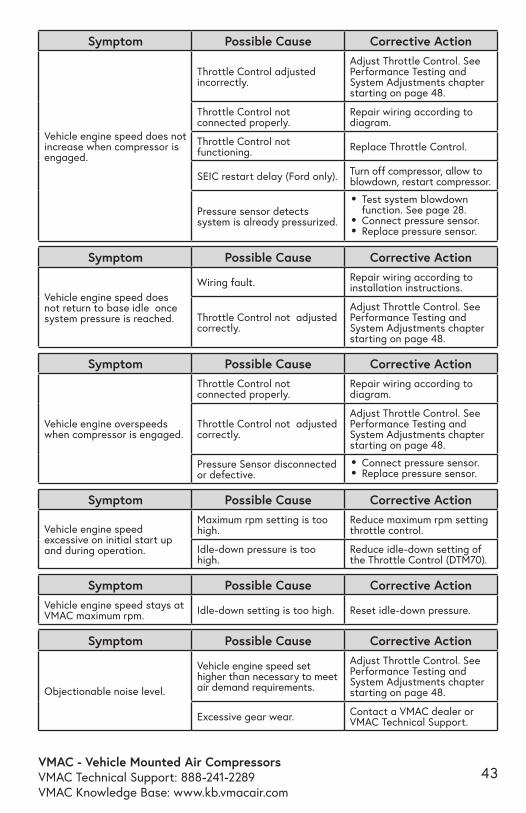
Symptom Possible Cause Corrective Action
Vehicle engine speed does not increase when compressor is engaged.
Throttle Control adjusted incorrectly.
Adjust Throttle Control. See Performance Testing and System Adjustments chapter starting on page 48.
Throttle Control not connected properly.
Repair wiring according to diagram.
Throttle Control not functioning. Replace Throttle Control.
SEIC restart delay (Ford only). Turn off compressor, allow to blowdown, restart compressor.
Pressure sensor detects system is already pressurized.
• Test system blowdown function. See page 28.
• Connect pressure sensor.• Replace pressure sensor.
Symptom Possible Cause Corrective Action
Vehicle engine speed does not return to base idle once system pressure is reached.
Wiring fault. Repair wiring according to installation instructions.
Throttle Control not adjusted correctly.
Adjust Throttle Control. See Performance Testing and System Adjustments chapter starting on page 48.
Symptom Possible Cause Corrective Action
Vehicle engine overspeeds when compressor is engaged.
Throttle Control not connected properly.
Repair wiring according to diagram.
Throttle Control not adjusted correctly.
Adjust Throttle Control. See Performance Testing and System Adjustments chapter starting on page 48.
Pressure Sensor disconnected or defective.
• Connect pressure sensor.• Replace pressure sensor.
Symptom Possible Cause Corrective Action
Objectionable noise level.
Vehicle engine speed set higher than necessary to meet air demand requirements.
Adjust Throttle Control. See Performance Testing and System Adjustments chapter starting on page 48.
Excessive gear wear. Contact a VMAC dealer or VMAC Technical Support.
Symptom Possible Cause Corrective Action
Vehicle engine speed excessive on initial start up and during operation.
Maximum rpm setting is too high.
Reduce maximum rpm setting throttle control.
Idle-down pressure is too high.
Reduce idle-down setting of the Throttle Control (DTM70).
Symptom Possible Cause Corrective ActionVehicle engine speed stays at VMAC maximum rpm. Idle-down setting is too high. Reset idle-down pressure.
VMAC - Vehicle Mounted Air CompressorsVMAC Technical Support: 888-241-2289
VMAC Knowledge Base: www.kb.vmacair.com44
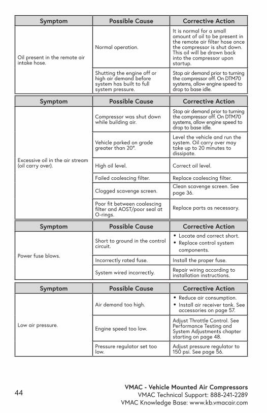
Symptom Possible Cause Corrective Action
Excessive oil in the air stream (oil carry over).
Compressor was shut down while building air.
Stop air demand prior to turning the compressor off. On DTM70 systems, allow engine speed to drop to base idle.
Vehicle parked on grade greater than 20°.
Level the vehicle and run the system. Oil carry over may take up to 20 minutes to dissipate.
High oil level. Correct oil level.
Failed coalescing filter. Replace coalescing filter.
Clogged scavenge screen. Clean scavenge screen. See page 36.
Poor fit between coalescing filter and AOST/poor seal at O-rings.
Replace parts as necessary.
Symptom Possible Cause Corrective Action
Power fuse blows.
Short to ground in the control circuit.
• Locate and correct short.• Replace control system
components.
Incorrectly rated fuse. Install the proper fuse.
System wired incorrectly. Repair wiring according to installation instructions.
Symptom Possible Cause Corrective Action
Low air pressure.
Air demand too high.• Reduce air consumption.• Install air receiver tank. See
accessories on page 57.
Engine speed too low. Adjust Throttle Control. See Performance Testing and System Adjustments chapter starting on page 48.
Pressure regulator set too low.
Adjust pressure regulator to 150 psi. See page 56.
Symptom Possible Cause Corrective Action
Oil present in the remote air intake hose.
Normal operation.
It is normal for a small amount of oil to be present in the remote air filter hose once the compressor is shut down. This oil will be drawn back into the compressor upon startup.
Shutting the engine off or high air demand before system has built to full system pressure.
Stop air demand prior to turning the compressor off. On DTM70 systems, allow engine speed to drop to base idle.
VMAC - Vehicle Mounted Air CompressorsVMAC Technical Support: 888-241-2289VMAC Knowledge Base: www.kb.vmacair.com
45
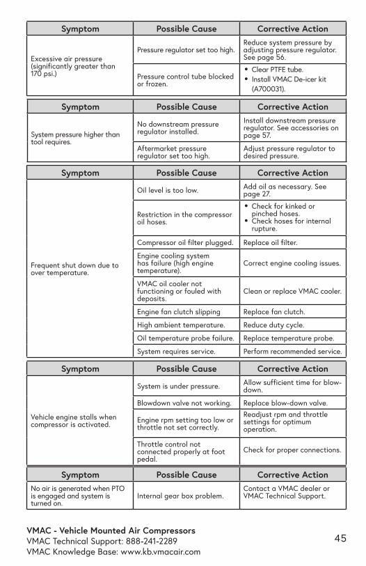
Symptom Possible Cause Corrective Action
Excessive air pressure (significantly greater than 170 psi.)
Pressure regulator set too high.Reduce system pressure by adjusting pressure regulator. See page 56.
Pressure control tube blocked or frozen.
• Clear PTFE tube.• Install VMAC De-icer kit
(A700031).
Symptom Possible Cause Corrective Action
System pressure higher than tool requires.
No downstream pressure regulator installed.
Install downstream pressure regulator. See accessories on page 57.
Aftermarket pressure regulator set too high.
Adjust pressure regulator to desired pressure.
Symptom Possible Cause Corrective ActionNo air is generated when PTO is engaged and system is turned on.
Internal gear box problem. Contact a VMAC dealer or VMAC Technical Support.
Symptom Possible Cause Corrective Action
Frequent shut down due to over temperature.
Oil level is too low. Add oil as necessary. See page 27.
Restriction in the compressor oil hoses.
• Check for kinked or pinched hoses.
• Check hoses for internal rupture.
Compressor oil filter plugged. Replace oil filter.
Engine cooling system has failure (high engine temperature).
Correct engine cooling issues.
VMAC oil cooler not functioning or fouled with deposits.
Clean or replace VMAC cooler.
Engine fan clutch slipping Replace fan clutch.
High ambient temperature. Reduce duty cycle.
Oil temperature probe failure. Replace temperature probe.
System requires service. Perform recommended service.
Symptom Possible Cause Corrective Action
Vehicle engine stalls when compressor is activated.
System is under pressure. Allow sufficient time for blow-down.
Blowdown valve not working. Replace blow-down valve.
Engine rpm setting too low or throttle not set correctly.
Readjust rpm and throttle settings for optimum operation.
Throttle control not connected properly at foot pedal.
Check for proper connections.
VMAC - Vehicle Mounted Air CompressorsVMAC Technical Support: 888-241-2289
VMAC Knowledge Base: www.kb.vmacair.com46
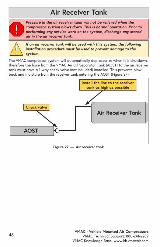
Pressure in the air receiver tank will not be relieved when the compressor system blows down. This is normal operation. Prior to performing any service work on the system, discharge any stored air in the air receiver tank.
If an air receiver tank will be used with this system, the following installation procedure must be used to prevent damage to the system.
The VMAC compressor system will automatically depressurize when it is shutdown, therefore the hose from the VMAC Air Oil Separator Tank (AOST) to the air receiver tank must have a 1-way check valve (not included) installed. This prevents blow back and moisture from the receiver tank entering the AOST (Figure 27).
Figure 27 — Air receiver tank
Install the line to the receiver tank as high as possible
Air Receiver Tank
Air Receiver Tank
AOST
Check valve
VMAC - Vehicle Mounted Air CompressorsVMAC Technical Support: 888-241-2289VMAC Knowledge Base: www.kb.vmacair.com
47
While the compressor system will function without the following accessories, VMAC strongly recommends their use for optimal performance.
See the “Accessory Product” section of this manual on page 47 for a list of products available for purchase through VMAC.
Receiver TankAn air receiver tank provides a buffer as it gives the compressor time to react by increasing the engine speed and producing air before the tool stalls. It also has the advantage of lowering the duty cycle of the compressor system.
Pressure GaugeWhile not critical to system performance, a pressure gauge is important for fine tuning the system and simplifies any potential troubleshooting.Install a 200 psi pressure gauge downstream of the air discharge valve.
Pressure Regulator and/or Lubricator or FRLThe compressor can produce air pressures up to approximately 150 psi (1035 kPa). It is the responsibility of the user to know the pressure and air flow requirements of the tools powered by the air compressor system. An appropriate air pressure regulator and lubricator can be installed downstream of the air discharge valve. Failure to regulate the air pressure may cause damage to the tool.
Recommended Accessories
VMAC - Vehicle Mounted Air CompressorsVMAC Technical Support: 888-241-2289
VMAC Knowledge Base: www.kb.vmacair.com48
Performance Testing and System Adjustments
If insufficient airflow is developed under high demand conditions, check the engine rpm. Some applications may require adjustments to provide the necessary airflow and pressure.
Engine rpm adjustments can be made to match the amount of air delivered by the system to the requirements of the tools or equipment that will be used.
Airflow and system pressure are related. If airflow demands on the system are low, the operating pressure will remain high. As airflow demands increase, the operating pressure will decrease. Adjustments to engine rpm affect cfm while maximum system pressure is adjusted via the pressure regulator.
By making adjustments to the engine speed while operating a specific tool, optimum performance will be achieved.
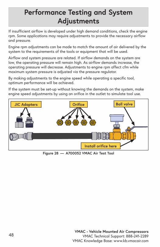
If the system must be set-up without knowing the demands on the system, make engine speed adjustments by using an orifice in the outlet to simulate tool use.
Figure 28 — A700052 VMAC Air Test Tool
Install orifice here
Orifice Ball valveJIC Adapters
VMAC - Vehicle Mounted Air CompressorsVMAC Technical Support: 888-241-2289VMAC Knowledge Base: www.kb.vmacair.com
49
Throttle Control
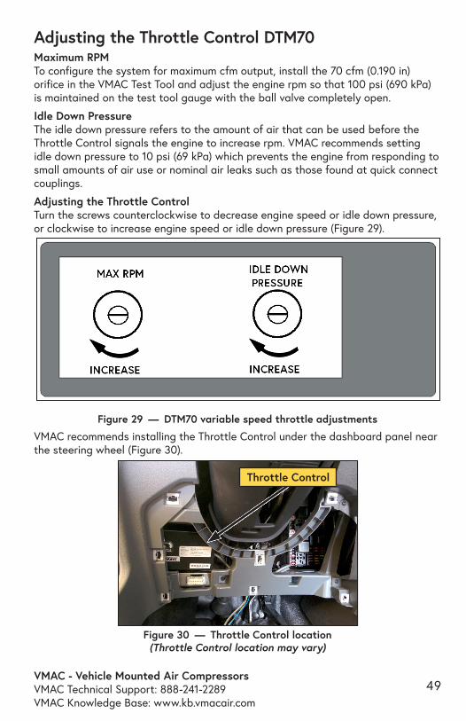
Adjusting the Throttle Control DTM70Maximum RPMTo configure the system for maximum cfm output, install the 70 cfm (0.190 in) orifice in the VMAC Test Tool and adjust the engine rpm so that 100 psi (690 kPa) is maintained on the test tool gauge with the ball valve completely open.
Idle Down PressureThe idle down pressure refers to the amount of air that can be used before the Throttle Control signals the engine to increase rpm. VMAC recommends setting idle down pressure to 10 psi (69 kPa) which prevents the engine from responding to small amounts of air use or nominal air leaks such as those found at quick connect couplings.
Adjusting the Throttle ControlTurn the screws counterclockwise to decrease engine speed or idle down pressure, or clockwise to increase engine speed or idle down pressure (Figure 29).
VMAC recommends installing the Throttle Control under the dashboard panel near the steering wheel (Figure 30).
Figure 29 — DTM70 variable speed throttle adjustments
Figure 30 — Throttle Control location (Throttle Control location may vary)
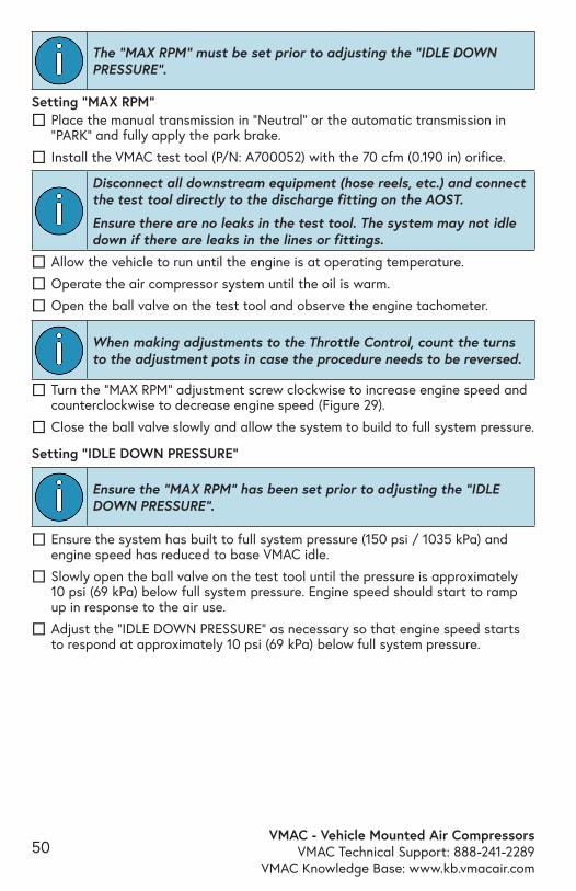
VMAC - Vehicle Mounted Air CompressorsVMAC Technical Support: 888-241-2289
VMAC Knowledge Base: www.kb.vmacair.com50
The “MAX RPM” must be set prior to adjusting the “IDLE DOWN PRESSURE”.
Disconnect all downstream equipment (hose reels, etc.) and connect the test tool directly to the discharge fitting on the AOST.
Ensure there are no leaks in the test tool. The system may not idle down if there are leaks in the lines or fittings.
☐ Allow the vehicle to run until the engine is at operating temperature.
☐ Operate the air compressor system until the oil is warm.
☐ Open the ball valve on the test tool and observe the engine tachometer.
When making adjustments to the Throttle Control, count the turns to the adjustment pots in case the procedure needs to be reversed.
Setting “IDLE DOWN PRESSURE”
Ensure the “MAX RPM” has been set prior to adjusting the “IDLE DOWN PRESSURE”.
☐ Ensure the system has built to full system pressure (150 psi / 1035 kPa) and engine speed has reduced to base VMAC idle.
☐ Slowly open the ball valve on the test tool until the pressure is approximately 10 psi (69 kPa) below full system pressure. Engine speed should start to ramp up in response to the air use.
☐ Adjust the “IDLE DOWN PRESSURE” as necessary so that engine speed starts to respond at approximately 10 psi (69 kPa) below full system pressure.
Setting “MAX RPM” ☐ Place the manual transmission in “Neutral” or the automatic transmission in “PARK” and fully apply the park brake.
☐ Install the VMAC test tool (P/N: A700052) with the 70 cfm (0.190 in) orifice.
☐ Turn the “MAX RPM” adjustment screw clockwise to increase engine speed and counterclockwise to decrease engine speed (Figure 29).
☐ Close the ball valve slowly and allow the system to build to full system pressure.
VMAC - Vehicle Mounted Air CompressorsVMAC Technical Support: 888-241-2289VMAC Knowledge Base: www.kb.vmacair.com
51
Compressor Performance Testing DTM70This system has been adjusted at the factory for general operation, not maximum cfm. Any performance testing should be done with the Throttle Control set for maximum cfm. See the previous page for instruction on adjusting the Throttle Control.
System operation can be tested using the tools that will be operated by the system or by using the VMAC Test Tool (A700052) with the 70 cfm (0.190 in) orifice in the outlet to simulate tool use.
Disconnect all downstream equipment (hose reels, etc.) and connect the test tool directly to the discharge fitting on the AOST.
Ensure there are no leaks in the test tool. The system may not idle down if there are leaks in the lines or fittings.
☐ Install the VMAC test tool at the system outlet with the 70 cfm (0.190 in) orifice.
☐ Ensure the ball valve is closed.
☐ Place the transmission in “PARK” and fully apply the park brake.
☐ Allow the engine to run until it is at operating temperature.
☐ Turn on the air compressor system and allow it to operate until the oil is warm.
☐ Observe the pressure gauge. Pressure should be approximately 150 psi.
☐ Open the ball valve on the test tool and observe the engine tachometer. Engine speed should increase to approximately 2,400 rpm - 2,800 rpm. The pressure on the gauge should be 90 - 120 psi.
☐ Close the air valve slowly to allow the system pressure to rise. When the pressure reaches 150 psi, the system will reduce the engine speed to base idle.
☐ Once the system pressure is at maximum, slowly open the ball valve on the test tool until the pressure on the gauge begins to drop. Engine speed should ramp up when the pressure drops to approximately 140 psi. Engine speed will increase as required to build air pressure to the 150 psi.
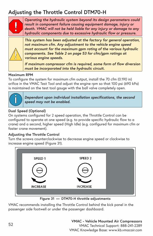
VMAC - Vehicle Mounted Air CompressorsVMAC Technical Support: 888-241-2289
VMAC Knowledge Base: www.kb.vmacair.com52
Adjusting the Throttle Control DTM70-H
This system has been adjusted at the factory for general operation, not maximum cfm. Any adjustment to the vehicle engine speed must account for the maximum gpm rating of the various hydraulic components. See Table 2 on page 53 for cfm/gpm ratings at various engine speeds.
If maximum compressor cfm is required, some form of flow diversion must be incorporated into the hydraulic circuit.
Maximum RPMTo configure the system for maximum cfm output, install the 70 cfm (0.190 in) orifice in the VMAC Test Tool and adjust the engine rpm so that 100 psi (690 kPa) is maintained on the test tool gauge with the ball valve completely open.
Figure 31 — DTM70-H throttle adjustments
Dependant upon individual installation specifications, the second speed may not be enabled.
Dual Speed (Optional)On systems configured for 2 speed operation, the Throttle Control can be configured to operate at one speed (e.g. to provide specific hydraulic flow to a crane) and a second, higher speed (High Idle) (e.g. configured for maximum cfm or faster crane movement).
Adjusting the Throttle ControlTurn the screws counterclockwise to decrease engine speed or clockwise to increase engine speed (Figure 31).
VMAC recommends installing the Throttle Control behind the kick panel in the passenger side footwell or under the passenger dashboard.
Operating the hydraulic system beyond its design parameters could result in component failure causing equipment damage, injury or death. VMAC will not be held liable for any injury or damage to any hydraulic components due to excessive hydraulic flow or pressure.
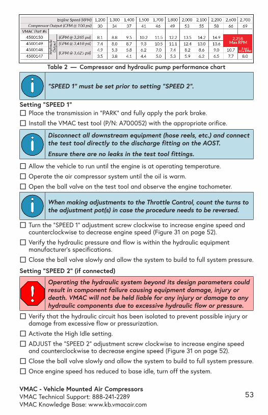
VMAC - Vehicle Mounted Air CompressorsVMAC Technical Support: 888-241-2289VMAC Knowledge Base: www.kb.vmacair.com
53
Table 2 — Compressor and hydraulic pump performance chart
“SPEED 1” must be set prior to setting “SPEED 2”.
Disconnect all downstream equipment (hose reels, etc.) and connect the test tool directly to the discharge fitting on the AOST.
Ensure there are no leaks in the test tool fittings.
☐ Allow the vehicle to run until the engine is at operating temperature.
☐ Operate the air compressor system until the oil is warm.
☐ Open the ball valve on the test tool and observe the engine tachometer.
When making adjustments to the Throttle Control, count the turns to the adjustment pot(s) in case the procedure needs to be reversed.
☐ Verify that the hydraulic circuit has been isolated to prevent possible injury or damage from excessive flow or pressurization.
☐ Activate the High Idle setting.
☐ ADJUST the “SPEED 2” adjustment screw clockwise to increase engine speed and counterclockwise to decrease engine speed (Figure 31 on page 52).
☐ Close the ball valve slowly and allow the system to build to full system pressure.
☐ Once engine speed has reduced to base idle, turn off the system.
Setting “SPEED 1” ☐ Place the transmission in “PARK” and fully apply the park brake.
☐ Install the VMAC test tool (P/N: A700052) with the appropriate orifice.
☐ Turn the “SPEED 1” adjustment screw clockwise to increase engine speed and counterclockwise to decrease engine speed (Figure 31 on page 52).
☐ Verify the hydraulic pressure and flow is within the hydraulic equipment manufacturer’s specifications.
☐ Close the ball valve slowly and allow the system to build to full system pressure.
Setting “SPEED 2” (if connected)
Operating the hydraulic system beyond its design parameters could result in component failure causing equipment damage, injury or death. VMAC will not be held liable for any injury or damage to any hydraulic components due to excessive hydraulic flow or pressure.
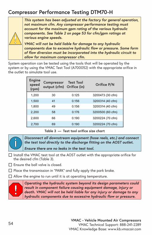
VMAC - Vehicle Mounted Air CompressorsVMAC Technical Support: 888-241-2289
VMAC Knowledge Base: www.kb.vmacair.com54
Compressor Performance Testing DTM70-H
Disconnect all downstream equipment (hose reels, etc.) and connect the test tool directly to the discharge fitting on the AOST outlet.
Ensure there are no leaks in the test tool.
This system has been adjusted at the factory for general operation, not maximum cfm. Any compressor performance testing must account for the maximum gpm rating of the various hydraulic components. See Table 2 on page 53 for cfm/gpm ratings at various engine speeds.
VMAC will not be held liable for damage to any hydraulic components due to excessive hydraulic flow or pressure. Some form of flow diversion must be incorporated into the hydraulic circuit to allow for maximum compressor cfm.
System operation can be tested using the tools that will be operated by the system or by using the VMAC Test Tool (A700052) with the appropriate orifice in the outlet to simulate tool use.
Engine speed (rpm)
Compressor output (cfm)
Test Tool Orifice (in) Orifice P/N
1,200 30 0.125 3200473 (30 cfm)
1,500 41 0.156 3200314 (40 cfm)
1,800 49 0.156 3200314 (40 cfm)
2,200 58 0.176 3200500 (60 cfm)
2,600 66 0.190 3200224 (70 cfm)
2,700 69 0.190 3200224 (70 cfm)
Table 3 — Test tool orifice size chart
☐ Install the VMAC test tool at the AOST outlet with the appropriate orifice for the desired cfm (Table 3).
☐ Ensure the ball valve is closed.
☐ Place the transmission in “PARK” and fully apply the park brake.
☐ Allow the engine to run until it is at operating temperature.
Operating the hydraulic system beyond its design parameters could result in component failure causing equipment damage, injury or death. VMAC will not be held liable for any injury or damage to any hydraulic components due to excessive hydraulic flow or pressure.
VMAC - Vehicle Mounted Air CompressorsVMAC Technical Support: 888-241-2289VMAC Knowledge Base: www.kb.vmacair.com
55
☐ Verify the hydraulic circuit has been isolated to prevent possible injury or damage from excessive flow or pressurization.
☐ Turn on the air compressor system and allow it to operate until the oil is warm.
☐ Observe the pressure gauge. Pressure should be approximately 150 psi.
☐ Open the ball valve on the test tool and observe the engine tachometer. Engine speed should increase to the appropriate rpm listed on Table 2 on page 53 and the pressure on the gauge should indicate approximately 90 - 120 psi.
☐ Close the air valve slowly to allow the system pressure to rise. When the pressure reaches approximately 150 psi, the system will close the inlet poppet preventing the system from building more air, however engine speed will remain elevated to maintain hydraulic flow and pressure.
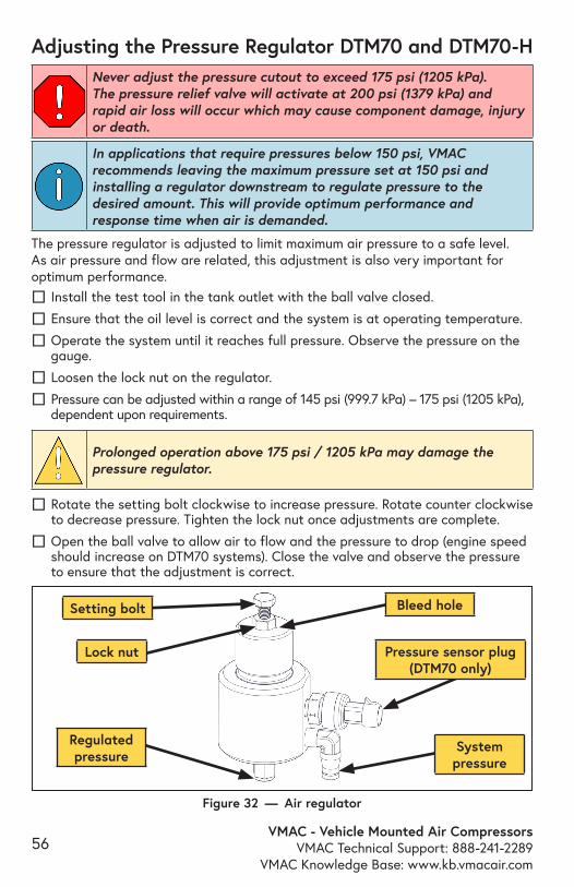
VMAC - Vehicle Mounted Air CompressorsVMAC Technical Support: 888-241-2289
VMAC Knowledge Base: www.kb.vmacair.com56
The pressure regulator is adjusted to limit maximum air pressure to a safe level. As air pressure and flow are related, this adjustment is also very important for optimum performance.
☐ Install the test tool in the tank outlet with the ball valve closed.
☐ Ensure that the oil level is correct and the system is at operating temperature.
☐ Operate the system until it reaches full pressure. Observe the pressure on the gauge.
☐ Loosen the lock nut on the regulator.
☐ Pressure can be adjusted within a range of 145 psi (999.7 kPa) – 175 psi (1205 kPa), dependent upon requirements.
Adjusting the Pressure Regulator DTM70 and DTM70-H
Prolonged operation above 175 psi / 1205 kPa may damage the pressure regulator.
Never adjust the pressure cutout to exceed 175 psi (1205 kPa). The pressure relief valve will activate at 200 psi (1379 kPa) and rapid air loss will occur which may cause component damage, injury or death.
☐ Rotate the setting bolt clockwise to increase pressure. Rotate counter clockwise to decrease pressure. Tighten the lock nut once adjustments are complete.
☐ Open the ball valve to allow air to flow and the pressure to drop (engine speed should increase on DTM70 systems). Close the valve and observe the pressure to ensure that the adjustment is correct.
In applications that require pressures below 150 psi, VMAC recommends leaving the maximum pressure set at 150 psi and installing a regulator downstream to regulate pressure to the desired amount. This will provide optimum performance and response time when air is demanded.
Figure 32 — Air regulator
Setting bolt
Lock nut
Bleed hole
Regulated pressure
System pressure
Pressure sensor plug (DTM70 only)
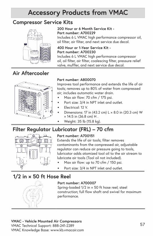
VMAC - Vehicle Mounted Air CompressorsVMAC Technical Support: 888-241-2289VMAC Knowledge Base: www.kb.vmacair.com
57
Accessory Products from VMACCompressor Service Kits
200 Hour or 6 Month Service Kit - Part number: A700229Includes 6 L VMAC high performance compressor oil, oil filter, air filter, and next service due decal.
400 Hour or 1-Year Service Kit - Part number: A700230Includes 6 L VMAC high performance compressor oil, oil filter, air filter, coalescing filter, pressure relief valve, muffler, and next service due decal.
1/2 in × 50 ft Hose ReelPart number: A700007Spring-loaded 1/2 in × 50 ft hose reel; steel construction; full flow shaft and swivel for maximum performance.
Air AftercoolerPart number: A800070Improves tool performance and extends the life of air tools; removes up to 80% of water from compressed air; includes automatic water drain.• Max air flow: 70 cfm / 175 psi.• Port size: 3/4 in NPT inlet and outlet.• Electrical: 12 V.• Dimensions: 17 in (43.2 cm) L × 8.0 in (20.3 cm) W
× 14.5 in (36.8 cm) H .• Weight: 35 lb (15.8 kg).
Filter Regulator Lubricator (FRL) – 70 cfmPart number: A700151Extends the life of air tools; filter removes contaminants from the compressed air, adjustable regulator can reduce air pressure going to tools, lubricator adds atomized tool oil to the air stream to lubricate air tools (Tool oil not included).• Max air flow: up to 70 cfm / 150 psi.
• Port size: 3/4 in NPT inlet and outlet.
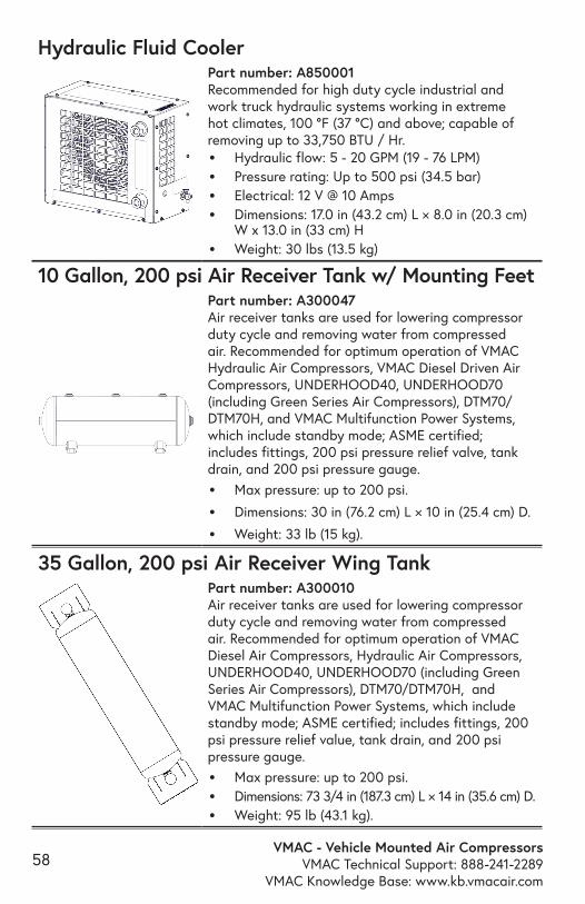
VMAC - Vehicle Mounted Air CompressorsVMAC Technical Support: 888-241-2289
VMAC Knowledge Base: www.kb.vmacair.com58
Hydraulic Fluid CoolerPart number: A850001Recommended for high duty cycle industrial and work truck hydraulic systems working in extreme hot climates, 100 °F (37 °C) and above; capable of removing up to 33,750 BTU / Hr.• Hydraulic flow: 5 - 20 GPM (19 - 76 LPM)• Pressure rating: Up to 500 psi (34.5 bar)• Electrical: 12 V @ 10 Amps• Dimensions: 17.0 in (43.2 cm) L × 8.0 in (20.3 cm)
W x 13.0 in (33 cm) H• Weight: 30 lbs (13.5 kg)
35 Gallon, 200 psi Air Receiver Wing TankPart number: A300010Air receiver tanks are used for lowering compressor duty cycle and removing water from compressed air. Recommended for optimum operation of VMAC Diesel Air Compressors, Hydraulic Air Compressors, UNDERHOOD40, UNDERHOOD70 (including Green Series Air Compressors), DTM70/DTM70H, and VMAC Multifunction Power Systems, which include standby mode; ASME certified; includes fittings, 200 psi pressure relief value, tank drain, and 200 psi pressure gauge.
• Max pressure: up to 200 psi.• Dimensions: 73 3/4 in (187.3 cm) L × 14 in (35.6 cm) D.• Weight: 95 lb (43.1 kg).
10 Gallon, 200 psi Air Receiver Tank w/ Mounting FeetPart number: A300047Air receiver tanks are used for lowering compressor duty cycle and removing water from compressed air. Recommended for optimum operation of VMAC Hydraulic Air Compressors, VMAC Diesel Driven Air Compressors, UNDERHOOD40, UNDERHOOD70 (including Green Series Air Compressors), DTM70/DTM70H, and VMAC Multifunction Power Systems, which include standby mode; ASME certified; includes fittings, 200 psi pressure relief valve, tank drain, and 200 psi pressure gauge.
• Max pressure: up to 200 psi.
• Dimensions: 30 in (76.2 cm) L × 10 in (25.4 cm) D.
• Weight: 33 lb (15 kg).
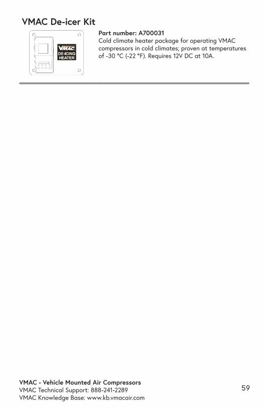
VMAC - Vehicle Mounted Air CompressorsVMAC Technical Support: 888-241-2289VMAC Knowledge Base: www.kb.vmacair.com
59
VMAC De-icer KitPart number: A700031Cold climate heater package for operating VMAC compressors in cold climates; proven at temperatures of -30 °C (-22 °F). Requires 12V DC at 10A.

VMAC - Vehicle Mounted Air CompressorsVMAC Technical Support: 888-241-2289
VMAC Knowledge Base: www.kb.vmacair.com60
Notes

VMAC - Vehicle Mounted Air CompressorsVMAC Technical Support: 888-241-2289VMAC Knowledge Base: www.kb.vmacair.com
61
Notes
VMAC - Vehicle Mounted Air CompressorsVMAC Technical Support: 888-241-2289
VMAC Knowledge Base: www.kb.vmacair.com62
Notes
VMAC - Vehicle Mounted Air CompressorsVMAC Technical Support: 888-241-2289VMAC Knowledge Base: www.kb.vmacair.com
63
Notes

VMAC - Vehicle Mounted Air CompressorsVMAC Technical Support: 888-241-2289
VMAC Knowledge Base: www.kb.vmacair.com64
Day Month Year
This form must be fully completed and returned to VMAC at the time of installation. Warranty may be void if this form is not received by VMAC within 30 days of installation.VMAC’s Warranty policy and registration can be viewed online at: www.vmacair.com/warranty
VMAC Dealer InformationCompany Name:
City: State / Province:
Installer InformationCompany Name:
City: State / Province:
Installation Date: / /
Owner InformationCompany Name:
Address:
City: State / Province:
Zip / Postal: Phone: ( ) –
Email Address:
Vehicle InformationYear: Make:
Vehicle Identification Number:
Unit:
Product InformationSystem Identification Number: D Compressor Serial Number: P Throttle Control Serial Number: AOST Serial Number:
Submitted byName: Contact:
Warranty Registration

888-241-2289 [email protected]
877-740-3202 [email protected]
www.vmacair.com www.kb.vmacair.com
1333 Kipp Road, Nanaimo, B.C., V9X 1R3 Canada
Manufactured by
®