Embed Size (px)
Citation preview

Air heaters B1LC compact /D1LC compact
Technical Description Eberspacher 'Operating Instructions Installation Instructions
J . Eberspa-sherGmbH & Co.Eoerspachersr.r 24 D-7373Q Esslingen
Tole-fon (2entral) (0711)9 39-03 Telefax(0? 11)939-0500
vwrt.cberspaechw.dQ
Engine-independent air heaters B 1 LC compact for gasoline D 1 LC compact for diesel fuel with integrated control unit
Specifications (margin of error ± 10%)
Heating medium
Fuel
Heating capacity control
Heating capacity”
Air
Gasoline(commercially available) or diesel fuel(commercially available)
High / Medium / Low / Off
Power High Medium Low 2200 1800 1200 850 W
Hot air throughput4* 110 95 65 65 kg/h
Fuel consumptionB 1 L C compact 0,30 0,24 0,16 0,12 l/hD 1 L C compact 0,27 0,21 0,14 0,10 l/h
Rated voltage
Operating range Minimum voltage21 Maximum voltage31
12 V o r 24 V
10,5V or 21 V 16 V o r 32 V
Air heater
B 1 L C compact
D 1 L C compact D 1 L C compact
Cat. No.
12V 20 1766050000
12V 2 5 1 9 7 6 0 5 0 0 0 0 24 V 25 1977 05 00 00
Universal installation kit, operating and unit and heater timers must be ordered separately as additional parts (see page 2).
01 L C compact, complete 12V 25 1979 05 00 00 D 1 L C compact, complete 24 V 25 1978 05 00 00 with universal installation kit and opening unit.See Additional Parts Catalog for further accessories.
Electric power consumption11
gt startB 1 L C compact 12 V = 250 W D 1 L C compact 12 V = 250 W
24 V = 210 Win operation Power / High 30 22
/ Medium 10
/ Low 10W
Radio interference suppression level 3
Weight
Ambient temperatureD 1 L C compact B 1 L C compact
Additional radio interference suppression measures possible
approx. 3.5 kg
in operation- 40 °C to + 70 °C- 40 °C to 4- 50 °C not in operation- 40°C to + 85 °C
1) at rated voltage.
an undervoltage safety device built into the control unit switches off the heater at about 10.5 V. or 21 V.
3) an overvoltage safety device built into the control unit switches off the heater at about 16 V or 32 V.
4) without backpressure.
25 1976 90 94 C6 07.2030 Subject to change Printed In Germany © J. Eberspacher GmbH & Co. B39

Contents Page
Scope of delivery / Cat Nos.................................................2Government regulations...................................................... 4Safety instructions................................................................ 4Typical installation / Installation position.......................... 5Installing the hea ter............................................................. 5Principal dimensions........................................................... 6Permissible installation positions / Fastening methods ... 6Running the heating a ir .......................................................7Running the combustion a ir ................................................8Running the exhaust............................................................ 8Fuel supply......................................................................9, 10Electrics / Wiring diagrams....................................... 11-15Function description..................................................1 6 - 17
Scope of supply
Quantify / Designation Order No.
1 Air heater B 1 L C compact - 12 V 20 1766 05 00 00
To be additionally ordered:1 Universal mounting kit 25 1976 80 00 00
1 Air heater D 1 L C compact - 12 V 25 1976 05 00 00
To be additionally ordered:1 Universal mounting kit 25 1976 30 00 00
or
1 Air heater D 1 L C compact - 1 2 V 25 1979 05 00 00 As a complete package*
1 Air heater D 1 L C compact - 24 V 25 1977 05 00 00
To be additionally ordered:1 Universal mounting kit 25 1976 80 00 00
or
1 Air heater D 1 L C compact - 24 V 25 1978 05 00 00 As a complete package’
* The complete package consists of:1 Air heater1 Universal mounting kit
Optional accessories1 Temperature sensor, external 25 1774 89 03 00
with line tract, 2 m long
1 Line tract. 4 m long 25 1688 89 09 00for the temperature sensor, external
1 Cable harness, ADR / TRS 0033 m long 25 1226 39 50 00
For further accessories, please refer to the accessories catalogue.
Control elements, optional
Quantity / Designation Order No.
1 Control unit 12 volt 25 1395 71 00 0024 volt 25 1896 71 00 00
Rotary switch lor ON / OFF and to adjust the heat flow.
1 Mini-clock - 12 / 24 volt 22 1000 31 31 00
Tbs mini-cock can fce combined with the TP 41 / TP 41 i 'adio remoie control.Additionally required The contra! unit to adjust the heat flow and the change-over switch ’heating / ventilating' fcr ventilation rrn de.
1 Module clock - 1 2 / 2 4 volt 22 1000 30 38 00with temperature preselection
*The modulo c'ock can be combined wilh ibs TP 4 / TP 4i radio remote control
1 Mounting parts ‘module clock' 25 1482 70 01 00
only required when installing with parol.
1 Radio remote control TP 4 22 1000 30 63 00/ 24 volt TP 4i* 22 1000 30 99 00
The radio remote control TP 4 / TP 4i can only be used in combination with too module clock.
1 Radio remote control TP 41 22 1000 31 35 001 24 volt TP 41 i* 22 1000 31 39 00
The radio remote control TP -11 / TP 41 j can be used on its own or in combination with the mini-clock, order No. 22 10C0 31 31 03
* Outside Germany, only the i-version radio remote controls may be permissible.
Please note!Control elements must be selected in accordance with the intended use of the heater, distinguishing between air or water heater, simple switching on and off. programme preselection and / or remote control.The control elements are supplied with operating instructions. These are intended for the customer together with the “Technical Description”.
%■ ic>5 •: .1 0. J
2
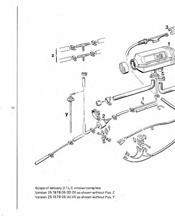
Scope of delivery D 1 L C compact complete Version 25 1978 05 00 00 as shown without Pos. Z Version 25 1979 05 00 00 as shown without Pos. Y
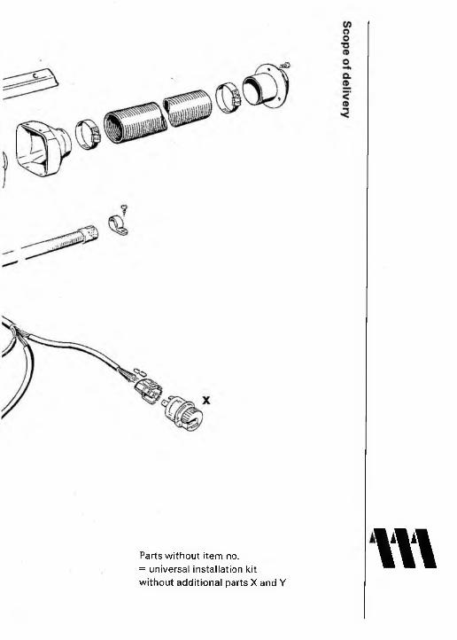
Parts without item no.= universal installation kit without additional parts X and Y
vv\

Government regulations concerning installationFor installation in motor vehicles that are subject to the Regulations Authorising the Use of Vehicles for Road Traffic (StVZO), the air heater has been approved by the (German) Federal Office for Motor Traffic in keeping with the "General Model Approval” (ABG), and the official test symbol is marked on the type plate of the air heater.
B 1 L C compact D 1 L C compact
m S 237 -WV S 221
The mounting requirements associated with the General Model Approval (ABG) have been printed in the corresponding sections of these mounting instructions. When the air heater is installed in special vehicles, then the regulations governing such vehicles must be taken into account (e.g. TRS 003 for vehicles used to transport dangerous substances).
The year in which the air heater was operated for the first time must be permanently recorded on the type plate. The works must print 3 years in the corresponding field c>f the type plate. The valid year is identified by removing those years that are not applicable.
Subsequent installation of the heater must be completed in conformity with these mounting instructions and must be accepted by an officially approved vehicle specialist or inspector (Section 7.4a of Annex VIII relating to StVZO) in conformity with § 19 Section 4 StVZO. The specialist / inspector must issue a corresponding written certificate. The effectiveness of model acceptance (ABG) for the heater depends upon this certificate.
The vehicle owner can choose the kind of certificate to be issued:* A separate "Acceptance Confirmation” must always be kept in the vehicle. Neu
tral acceptance confirmations of the motor vehicle specialist are also permissible. The vehicle manufacturer, the vehicle type and the vehicle identification number must all be entered in both cases.
• Entry in the vehicle registration book (by the assessing agency) and in the motor vehicle certificate (by the approving agency).
For vehicles that are not subject to StVZO (e.g. ships), it is necessary to observe the specific rules and mounting instructions applicable to the given vehicle; these can differ regionally.
The heater must be installed in keeping with these mounting nstructions or possibly other special installation recommendations by a workshop approved by the manufacturer.
The installation points suggested in these mounting instructions are examples. Alternative installation points are permissible provided they conform with the general installation requirements and, possibly, after consulting the manufacturer. This applies particularly to the electrical wiring (circuit diagram), the fuel supply, conducting the combustion air and exhaust gas and the use of alien operating and controlling elements. This is only permissible with the written approval of the manufacturer.
The sticker "Turn off the heater prior to refuelling", included with the heater, must be applied at an appropriate point on the vehicle (near the fuel tank cap).
Further mounting information (e.g. for boats and ships) can be requested from the manufacturer.
Safety instructions concerning installationEvery combustion process produces exhaust gas that contains toxic substances. Consequently, and on account of the high temperatures, the exhaust gas must be conducted in conformity with the requirements specified in these mounting instructions.
Fuel pipes and exhaust pipes must be safely fastened, to avoid damage from vibrations (recommendation: at intervals of approx. 50 cm).
The hot-air emitter (possibly adjustable) must always be arranged in such a manner that the hot air is not directly blown onto heat-sensitive parts of the vehicle. People and loose objects must not be directly exposed to the blown hot air. To avoid damage and burns, people and loose objects must no: be directly exposed to the blowing hot air.
If there is no suction hose, then the suction side of the heater must be covered with a protective grille to prevent injury from the hot-air blower.
The heater may only be started up when the maintenance flap is closed.
The maintenance flap may not be open during operation.
Ensure that the insulation of electrical lines cannot be damaged due to abrasion, kinking, squeezing or by exposure to heat.
As a result of their concept for mobile service, the heaters are not suitable as permanent heating installations (for instance to heat living rooms).
Government regulations concerning operationSubsequent installation of the heater must be completed in conformity with these mounting instructions and must be accepted by an officially approved vehicle specialist or inspector (TOV, DEKRA) in conformity with § 19 Section 4 StVZO (Regulations Authorising the Use of Vehicles for Road Traffic), who must issue a corresponding written certificate, either by entry in the vehicle papers (vehicle registration book or motor vehicle certificate), or as a separate “Acceptance Confirmation” that must always be kept in the vehicle. The effectiveness of model acceptance for the heater (ABG) depends upon this certificate.
The heater must only be used for the purpose specified by the manufacturer with due consideration of the “Technical Description / Mounting Instructions" and the "Operating Instructions” included with each heater.
It is not permissible to operate the heater where combustible vapours or dusts can be formed, e.g. in the vicinity of fuel, coal, wood and grain stores and similar facilities.
The heater must not be used in closed rooms, e.g. in a garage or car park building. This is because of the danger of poisoning since all combustion processes produce exhaust gases that contain toxic constituents.
The heater must be turned off when refuelling.
With vehicles subject to TRS regulations (transport of dangerous products, e.g. road tankers), the heater must be switched off before entering the hazardous area (refinery, petrol statior, etc.).
In conformity with StVZO, the heater must be exchanged for an original replacement heater by the manufacturer or an authorised workshop 10 years after the heater was first used. The vehicle owner / operator of the heater is responsible for ensuring replacement. A plate must then be mounted (not detachable) on the replacement heater indicating the date when the replacement heater was installed, together with the designation "Original Part" (the plate is supplied with the replacement heater).
D.I.Y. repairs (on your own and without using original spare parts) are dangerous and therefore not permitted. The General Model Approval (ABG) for the heater and the General Operating Permit (ABE) for the vehicle will both become :nvalid.
The manufacturer's guarantee for the entire heating system will become invalid if the above instructions are not observed. The Eterspacher Guarantee Conditions are exclusively applicable.
The observance of the pertinent regulations and safety instructions is a precondition for liability claims. The Eberspacher company cannot be held liable if the ''Operating Instructions” have not been observed and If repairs have not been competently completed, even if original spares were used.
I^ l Safety instructions concerning operationAs a result of its concept for mobile service, the heaters are not suitable as permanent heating installations (for instance to heat living rooms).
The installation space of the heater must remain tree and cannot be used as storage space. Reserve fuel tanks, oil cans, spray cans, gas cartridges, fire extinguishers, cleaning cloths, clothes, paper, etc., must not be stored or transported on or alongside the heater.
The protective grille over the suction side should be occasionally inspected, but particularly before the heating period, and cleaned should this prove to be necessary.
An adjustable hot-air emitter must always be arranged in such a manner that hot air is not directly blown onto heat-sensitive parts of the vehicle. People and loose objects must not be directly exposed to the stream of hot air. To avoid carnage and burns, people and loose objects must not be directly exposed to the stream of hot air.
Defective fuses must only be replaced by fuses with the prescribed fuse rating.
Should fuel leak out of the heater's fuel system, then the damage must be immediately rectified by an authorised servicing workshop.
The heater should be tested before the beginning of the heating period. The heater must be turned off, and the fuse removed so that it is inoperable, should intense smoke develop for an extended period, if unusual burner noises can be heard, if there is a distinct smell of fuel or if electric / electronic parts become overheated. Renewed operation of the heater is only permissible after it has been checked by trained specialist Eberspacher personnel.
Damage to the actual heater or the heating installation must only be remedied by an authorised servicing workshop which will only use original spare parts
4
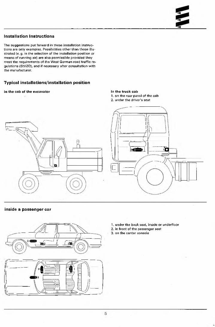
Installation Instructions
The suggestions put forward in these installation instructions are only examples. Possibilities other than those illustrated (e.g. in the selection of the installation position or means of running air) are also permissible provided they meet the requirements of the West German road traffic regulations (StVZO), and if necessary after consultation with the manufacturer.
Typical installations/installation position
in the cab of the excavator in the truck cab1. on the rear panel of the cab2. under the driver's seat
inside a passenger car
1. under the back seat, inside or underfloor2. in front of the passenger seat3. on the center console

Installing the heater
The B 1 L C com pact! D 1 L C compact heaters are suitable and approved for installation in vehicle areas used by persons. Installation in the driver or passenger areas of motor buses* is not permitted.
The electronic control device is integrated in the heater. This facilitates wiring during installationThe heaters are suitable for installation in cabins of vehicles transporting hazardous goods and, if wired with the appropriate cable harness (see wiring diagram), meet TRS 003.
For this reason the heater must be fitted by its base on an outside panel of the vehicle or on the vehicle floor, using the seal seated on the base.The factory plate must be clearly visible when the heater is installed. If necessary a second plate (duplicate) with the same information as the original can be affixed to a point on the heater clearly visible after installation or to a cover located in front of the heater. A second plate is not necessary if the original is visible after removal of a cover without the aid of tools.
* Vehicles with more than 9 seats.
Principal Dimensions360
Permissible installation positions
%rar
The heater should be installed in the standard position as shown. See sketch for maximum permissible deviations.
Please consult the manufacturer if further differences are required.
During starting and thermostatic operation a heater installed in the standard position may deviate, due to the inclination of the vehicle during motion, up to ± 15° in both axes from the standard position.
Continuous heating operation after starting is possible at a deviation of up to ± 30° from the standard position. With deviations exceeding ± 30° reliable heating operation is no longer possible. However, this does not lead to damage of the heater if the changes in the operating position are only for brief periods.
Important; the plug connection must always point upwards.

Fastening to the vehicle wall/floor
Make penetrations in accordance with the template pattern.
The hoie for the cable leading to the metering pump is not included in the template and must be drilled to suit the installation method.
The mating surface for the heater base must be smooth. To drill the penetrations and if necessary to smooth the mating surface a special tool is available from the manufacturer under Cat. No. 99 1 201 46 53 29.
Special tool
Check for free turning of fan wheel.
i \ .- \ r
This must be smooth
* This must be kept free
Heater baseSeal
If the mating surface sheet is too thin (criterion: thinner than 1.5 mm), a reinforcing plate, Cat. No. 20 1 577 89 00 03 can be installed additionally on the outside.
Springwasher
Vehicle panel
Running the Heating Air - Parts for running the heating air included in the scope of delivery for the universalinstallation kit
1 Protective grid2 Reducing piece3 Hose clip, dia. 50 mm to dia. 70 mm
When checking an installation the average output temperature should not significantly exceed 100°C at the output point with an intake temperature of 20°C. This will ensure that the safety thermal cutout switch will not respond under normal operating conditions.
4 Flexible pipe, dia. 60 mm (1 m + 1 m)5 Air outlet, rotatable6 Connection piece, dia. 60 mm
Heating air intake openings shall be arranged in such a manner that exhaust from the vehicle's engine and from the heater cannot be expected to be sucked in under normal operating conditions, and the heating air cannot be contaminated.
When operating as a recirculating heater, locate the inlet for the heating air in such a way that the outflowing hot air cannot be sucked directly in again.
7

Running the combustion air/Running the exhaust
Permissible diameters, lengths, bends of combustion air and exhaust lines.
Silencer (optional)
r t f
min. 0,2-max.2m
Protect from slipstream, snow, dirt and water.
Combustion air
Silencer (optional)
r t t
min. 0,2 -max. 2m
Exhaust
■©.
r fProtect from slipstream, snow, dirt and water.
Permissible diversions - exhaust line: max. 180°; combustion air line: max. 180°.
The scope of delivery includes a flexible exhaust pipe,24 mm internal dia., 1 m long. This can be shortened as required. For longer pipes see the Additional Equipment Catalog.
The scope of delivery includes a flexible combustion air pipe, 20 mm internal dia., 1 m long. This can be shortened as required. For longer pipes see the Additional Equipment Catalog.
Additional noise suppression is possible by installing an exhaust silencer or combustion air silencer (see Additional Equipment Catalog). The permissible overall length, including silencer, remains unchanged.
The combustion air must be sucked in from the outside, not from the passenger compartment or trunk.
Do not install the intake opening facing the slipstream, but run it in such a manner that dirt and snow cannot enter and that any water which does enter can flow out.
Exhaust lines must not project beyond the sides of the vehicle. They must be laid either with a slight slope or with5 mm dia. holes at the lowest points for draining off condensate.
Arrange the exhaust outlet and the combustion air opening such that the exhaust cannot be sucked back in directly.
The exhaust outlet must be on the outside. Exhaust lines must be laid in such a way that neither the penetration of exhaust into the vehicle interior nor the intake of exhaust through the vehicle or heater blowers need be expected^ .and that the operation of essential vehicle parts is not affected (ensure adequate clearance). Place the outlet opening of the exhaust line in such a way that it cannot be clogged by dirt and snow and that any water which does enter can run off. Do not install facing the slipstream.
15 This requirement is deemed met when the outlet of the exhaust pipe points upwards or to the side, or — when the exhaust is run under the vehicle floor — is positioned close to the side or rear edge of the cab or vehicle.

Fuel supplyDivergences from the instructions set forth here are not permitted, as they can iead to malfunctions.1. For cars w ith diesel engines, and for cars w ith petrol engines having mechanical pump.
Fuel tapped from the fuel supply line to the engine.Precondition: The fuel line from the fuel tank to the engine must be leak-free, so that there is no break in the fuel column
when the engine is not running.Fuel connection to heater
Dimension a = max. 2 m with petrol max. 5 m with diesel
Dimension b= 50 mmDimension c — max. 300 mm Dimension d= max. 4 m with petrol
max. 6m with diesel
2. For cars with petrol injection engines and for trucks with diesei engines.Tapping fuel from the supply line downstream of the delivery pump is prohibited in cars, since pressures of up to 10 bars can occur.
The following possibilities are available:2.1 Tapping fuel - where possible - using a separate riser pipe, fitted to the fuel tank fitting in the case of cars, an directly into
the fuel tank in the case of trucks.
Fuel connection to heater
Dimension a = max. 2 m with petrol max. 5 m with diesel
Dimension d = max. 4 m with petrol max. 6 m with diesel
2.2 If it is not possible to fit a separate riser pipe in the case of cars with petrol injection engines, the return line can be tapped using a T-piece.Conditions:1. There must be no valve installed in the return line of the fuel tank.2. The pressure in the return line must not exceed 2 bars. For pressures greater than 0.3 bars and up to 2 bars, a pressure
reducing valve {additional equipment Cat. No. 201645 89 30 00} must be provided upstream of the metering pump.2.3 If it is not possible to fit a separate riser pipe in the case of trucks with diesel engines, the fuel supply line can be
tapped (as shown under 1.).
1 Fuel tank (vehicle tank or separate tank)2 Fuel branch3 Fuel hose, internal dia. 5 mm
Cat No. 360 75 3504 Fuel pre-filter
(only necessary when contaminated fuel is used) Cat. No. 25 1226 89 00 37
5 Fuel metering pump (15° to vertically upwards)6 Fuel hose, internal dia.3.5 mm
Cat. No. 360 75 300
7 Fuel pipe, plastic, internal dia. 1.5 mm Cat. No. 090 31118For D 1 L C compact also permissible: Fuel pipe, plastic, internal dia. 2 mm, Cat. No. 090 31117
8 Riser pipe, internal dia. 2 mmexternal dia. 4 mm
9 Connection socketexternal dia. 4 mm
10 Riser pipe, internal dia. 2 mm Cat. No. 25 1226 89 50 00external dia. 6 mm
11 Fuel pipe, internal dia. 2 mm Cat. No. 090 31125
Cat. No.20 1645 89 35 00

3. Permissible suction and pressure heads for installation per 1„and 2.; permissible positioning of metering pump
max. fuel levelFuel line connection to heater
Metering pump
min.fuel level
Supply pressure from tank to metering pump: e = max. 3000 mm suction head: tank at zero pressure
f = max. 500 mm with gasoline f = max. 1000 mm with diesel oil
Check whether tank ventilation works properly
intake from tank when underpressure occurs during (operation vaive 0.03 bar in tank cap) f = max. 150 mm with gasoline f — max. 400 mm with diesel oil
Pressure head metering pump to heater: g = max, 2000 mm
Fuel line metering pump to heater should not have a slope if at all possible.
2. ImportantProtect fuel lines, filter and metering pump from overheating; do not install near silencers and exhaust pipes. Temperatures above 30°C lead to gas bubbles and problems with gasoline.
When installing the fuel line, fuel filter and fuel metering pump near the rear axle, be sure to takte the spring deflection of the rear axle into consideration.
Cut fuel tubes and pipes to length only with a sharp knife. Cuts may not be indented and must be burr-free.
For connection of the fuel branches, always use rubber tuhing, never plastic pipe.
Fuel pipes connected by means of a fuel tube. Fuel pipe sections must abut.
bubble
right
Do not let fuel tube sag.
wrong
wrong
D 1 L C compactFuel grades/Fuel at low temperaturesThe heater can take without problem the same fuel you use in your tank. In the USA diesel fuel no. 1 and no. 2.Admixture of used oil is not permitted.
The refineries automatically adapt their fuels to normal winter temperatures (Winter Diesel).
Therefore difficulties can only arise at extremely-low temperature (as in the engine - see the vehicle's instruction manual).
If the heater is operated from a separate tank, the foltowing rules must be observed: at temperatures above 0°C any type of diesel fuel can be used.
If no special cold-weather diesel fuel is available at low temperatures, mix kerosine or gasoline according to the adjacent table.
Temperature
From 0°C to - 1 5°C*
From -1 5°C to -25° C
From -2 5 °C to -4 0 °C
Winter diesel oil
100% 50%
Additive
50% kerosine or gasoline
100% kerosine*
* or special winter diesel oils** or in accordance with fuel manufacturer's specifications
The fuel line and the fuel pump must be filled with new fuel by operation for 15 minutes.
Fuel for special casesIn special cases, the heaters can also be operated on extra light fuel oil (above 0°C) or kerosine. If in doubt consult the manufacturer.
10

Heating operation at high altitudes:up to 1500 m: Unrestricted heating operation, above 1 500 m: Heating operation is possible during a short
stay (e.g. crossing a mountain pass, taking a rest). If a longer stay is planned (e.g. winter camping), the fuel has to be adapted to the altitude. In this case, please consult the heater manufacturer for advice.
Elektrics:
Arrange electric cables, switches and control units in the vehicle in such a way that their correct functioning cannot be impaired under normal operating conditions.
The pilot light (built into the operation unit) should be within the field of vision of the driver, or at least be visible to him without great effort.
When carrying out electric welding work on the vehicle, disconnect the positive terminal from the battery and earth it in order to protect the control unit.
Operating unit and Mini-timer
The operating unit (see page 2 for Cat. No.) comprises the On-Off switch with controller for the heating capacity, a red light for illumination, and a green operation pilot light. Two scale discs are supplied with the operating unit.
Scale disc 1 is fitted if operation is exclusively with the operating unit. The operating unit then serves as an On- switch and temperature controller.
Scale disc 2 is fitted if a Mini-timer is used for actuation. Switch-on is then exclusively with the Mini-timer, and the temperature is selected with the rotary knob. See wiring diagram for connection.Remove the protective film before fitting.
Permissible clearance for operating button 0,5 to max. 1. mm.
The following cable cross-sections must be observed between battery and heater, in order that the maximum permissible voltage losses in the cables (0.5 at 12V rated voltage and 1 V at 24 V) are not exceeded.
Length + and — < 5 m -*• cross-section 4 mm2 Length + and — 5 to 8 m -> cross-section 6 mm2
If the positive cable is to be connected to the fuse box (e. g. terminal 30), the vehicle's cable too from the battery to the fuse box must be included in the calculation of the total line length, and if necessary redimensioned in accordance with the above.
Smear plug and earth connections with contact protection grease outside the vehicle interior.
Temperature control
The >High/Medium/Low/Off< settings are provided for temperature control.
A temperature sensor is arranged on the intake side of the heater, and - in conjunction with the controller of the operating unit - switches the heater to "High", "Medium" or "Low" or "Off" depending on intake temperature and controller setting.This type of temperature sensor is only suitable for recireu- lated-air operation (heating air intake from the space being heated).If the heater is operated with fresh air, an external temperature sensor (for Cat. No. see page 2) must be fitted in the interior and connected according to the wiring diagram. The sensor must not be attached to uninsulated outer panels, and must be protected from draughts and direct sunlight. See w iring diagram for connection.
11
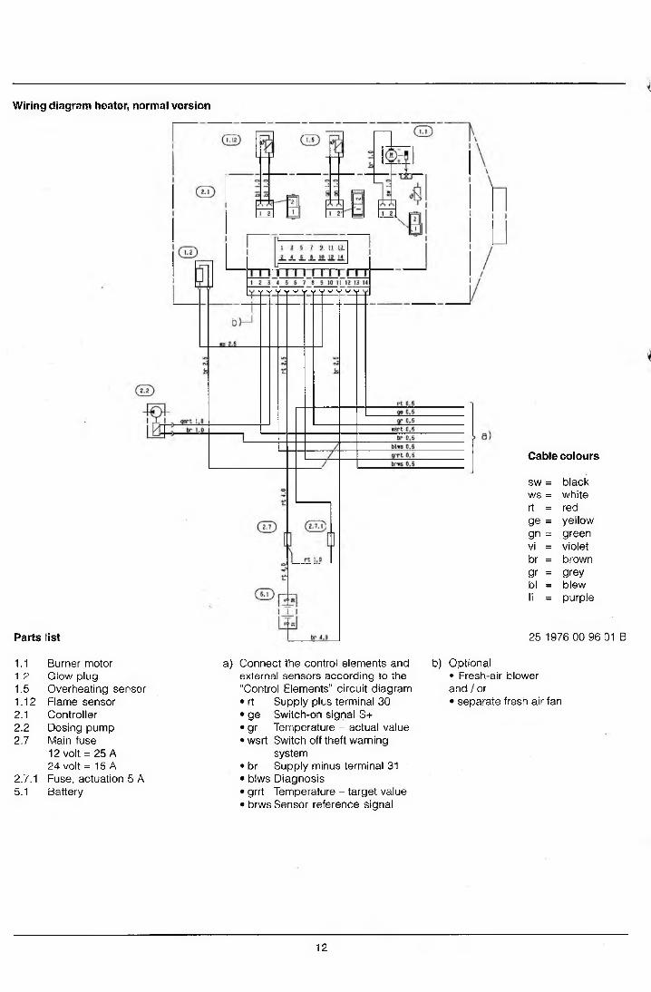
Wiring diagram heater, normal version
Parts list
Cable colours
sw = blackws = whitert = redge = yellowgn = greenvi = violetbr = browngr = greybl = blewli = purple
25 1976 00 96 01 B
1.11.21.51.122.12.22.7
2.7.15.1
Burner motor Glow plug Overheating sensor Flame sensor Controller Dosing pump Main fuse12 volt = 25 A24 volt = 15 A Fuse, actuation 5 A Battery
a) Connect the control elements and external sensors according to the “Control Elements” circuit diagram• rt Supply plus terminal 30• ge Switch-on signal S+• gr Temperature - actual value• wsrt Switch off theft warning
system• br Supply minus terminal 31• blws Diagnosis• grrt Temperature - target value• brws Sensor reference signal
b) Optional• Fresh-air blower and / or• separate fresh air fan
12

Circuit diagram, control elements
(Tip
QlM?|3Ml5|t|?T7iro
Parts list
2.15.1 Sensor, room temperature 2.15.9 Sensor, outside temperature3.1.11 Operating unit3.1.16 Momentary-contact switch3.2.8 Module clock3.2.12 Timer3.3.6 Radio receiver3.9.1 Diagnosis unit, JE diagnosis
a) Connect the control elements to the heater• rt Supply plus terminal 30• ge Switch-on signal S+• gr Temperature - actual value• wsrt Switci off theft warning system• br Supp y minus terminal 31• blws Diagnosis• grrt Temperature - target value• brws Connection to earth for external temperature
sensor and temperature target value
b) Terminal 15 - necessary when connecting TP 4
c) Lighting terminal 58
d) Connection for diagnosis unit
e) Connection for external temperature sensor
g) Connection for external heater key ®
h) Connection for TP4 remote control
j) Connection for outside temperature sensor
k) When connecting an automatic switch or radio receiver - cut open wire at this point
I) Connection change-over switch ‘heating / ventilating’ (optional). How to start: operate change-over switch ‘heating / ventilating’, then switch on the heater.
Cable ends that are not being used must be insulated.
Plug and socket case are shown from the cable entry side.
Cable colours
sw = black25 1 895 00 97 02 A _ vvhite
rt = redge = yellowgn - greenvi = violetbr - brown
gr = greybl = blewli = purple
13

Wiring diagram heater, version ADR / TRS 003 / TMD
T ~ r r m ~ n r r r T T i~ T i1 2 3 4 5 6 7 8 9 10 !! 12 13 14
Parts list GD
1.1 Burner motor1.2 Glow plug1.5 Overheating sensor1.12 Flame sensor2.1 Controller2.2 Dosing pump2.7 Main fuse
12 volt = 25 A; 24 volt = 15 A2.7.1 Fuse, actuation 5 A4.5.1 Diode TRS5.1 Battery5.2.1 Battery operating switch d)
(operation e.g. controlled via ignition lock)
Cable colours
sw = blackws - whitert = redge - yellowgn = greenV! - violetbr = browngr = greybl - blewli = purple
a)
Emergency-shutclown function in the case of ADR / TRS 003 / TMD - item 5 .2 .2 -5 .55.2.2 Battery separating switch d)5.3 Accessory drive HA+5.3.1 Switch auxiliary drive 5.5 Generator D+
Connect the control elements and external sensors according to the “Control Elements" circuit diagram• rt Supply plus terminal 30• ge Switch-on signal S+• gr Temperature - actual value• wsrt Switch off theft warning
system; Feedback to ADR / TRS 003 / TMD switch clock
• br Supply minus terminal 31• blws Diagnosis• grrt Temperature - target value• brws Sensor reference signal
b) Optional• Fresh-air blower and / or
. • Vehicle fan control
25 1976 00 96 02 B
c) Wiring if operated subject to ADR / TRS 003 / TMD (transporters carrying dangerous substances in the utility vehicle sector, e.g. road tanker)
d) If only one control element is used for items 5.2.1 and 5.2.2, it must be ensured that, if the function opening of battery separating switch’ is actuated (emergency shutdown-function in the case of ADR, TRS 003, TMD and similar), the switch always breaks contact without delay (without consideration for the heater mode) and breaks all of the heater’s circuits from the battery.
14

Circuit diagram, control elements - ADR / TRS 003 / TMD
r rt0.5
ge 0. 5
gr 0.5 I---------------------------------- kC =7I
T l< br 0.5 I
4
a |grrt 0.5 I
brws fl. 5 \r i - t t S " * £
(3 . 1.11)
rt 0. 5
ge 0.5
gr 0.5wsrt 0.5 Jjr 0J__ ,bl*Sj)J5_ grrt 0.5 br*s 0.5
~ T '. -U
i_ .
B6K [-F f
—k U 4O-
"1 t ! : !d z z r
B5
i 10 !s 5 8IIi 3 6 912 1
86
Oil I | 2 | 3 I * I S iTTfTn-pCable colours
sw = blackws = whitert = redge = yellowgn = greenvi = violetbr = browngr = greybl = blewli = purple
Parts list 25 2069 00 99 01 A
2.15.1 Sensor, room temperature3.1.11 Control unit, round3.2.8 Module clock (ADR / TRS 003 / TMD -
potentiometer)3.9.1 Diagnosis, JE-diagnosis
a) Connect the control elements to the heater• rt Supply plus terminal 30• ge Switch-on signal S+• gr Temperature - actual value• wsrt Feedback to ADR / TRS 003 / TMD switch clock
Switch off theft warning system• br Supply minus terminal 31• blws Diagnosis• grrt Temperature - target value• brws Connection to earth for external temperature
sensor and temperature target value
b) Terminal 15c) Lighting terminal 58d) Connection for diagnosis unite) Connection for external temperature sensor g) Connection for external heater key GD
Cable ends that are not being used must be insulated.
Plug and socket case are shown from the cable entry side.
15

Functional description
Controls
1. Operating unitThe operating unit is for switching the heater on and off and for setting the desired cabin temperatures (intake air temperature between 10 °C and 30 °C). The integrated green LED indicates wheter the heater is on.
2. Heater timer (optional)With the heater timer, the heater can be switched on or off immediately or the switch-on time preset (between 24 h and 7 days depending on version).
Mode of operation
Switch-onThe green pilot light comes on when the heater is switched on. The glow plug is switched on and the blower starts up at a low speed.Note: If the heat exchanger still contains residual heat, only the blower runs (cold-blowing phase). The start-up procedure commences after residual heat has dissipated.
Start-up procedureFuel feed starts after approx. 15 seconds. The fuel/air mixture ignites. Blower speed and fuel feed are increased continuosly. Once a flame has been detected and the combustion process has stabilized, the glow plug is switched off. The heater is heated up rapidly in the >P0WER< setting at maximum heat flow until the heat exchanger reaches its operating temperature.Note: The duration of max. heat flow is temperature- dependent.
Control during heatingDuring heating, the cabin temperature or the intake heating air temperature is measured constantly and compared with the temperature set at the operating unit. If the measured temperature exceeds the desired cabin temperature, the heater switches to the >LOW< setting and continues to run at low blower motor speed. If the heating capacity in the >LOW< setting is insufficient, the heater switches to the >MEDlUM< setting. The blower continues to run at low speed. In most cases, the LOW-MEDIUM-LOW control sequence at low blower speed will supply the required heat.If the >MEDIUM< setting is not sufficient, the heater switches back to >HIGH<. This again entails full blower speed. If, in special cases, an even lower heating capacity is required than the heater delivers in the >LOW< setting, the heater switches to the >OFF( setting. Restart is generally in the >MEDIUM< setting at low blower motor speed.
Switch-offWhen the heater is switched off, the green pilot light goes out and the fuel feed is shut off. The blower continues to run to cool down the heater.
The glow plug remains switched on for another 15 seconds to clear the heater of combustion residues.
Note: If no fuel feed took place during the start-up procedure or if the heater is in the >OFF< setting, the heater is switched off immediately without afterrun.
Once the normal afterrun period has elapsed, the heater is constantly after-ventilated at minimum blower speed (in re- circulated-air operation only) until the heater is restarted.
Controls and safety equipmentThe flame is monitored by the flame sensor, and the max. permissible temperature by the safety thermal cutout switch. Both affect the control unit, which shuts down the heater in the event of faults.
1. If the heater fails to ingnite within 90 seconds of fuel starting to be pumped, starting is repeated as described. If the heater still fails to ignite after 90 seconds of fuel pumping, fault shutdown takes place.
2. If the flame goes out spontaneously during operation, a restart is first attempted.If the heater fails to ignite within 90 seconds of fuel pumping, or if it does ignite but goes out again within 10 minutes, fault shutdown takes place.The heater can be reset by switching it off and then back on again.
3. In the event of overheating the safety thermal cutout switch is operated, the fuel supply is interrupted, and fault fault shutdown takes place.If the fault shutdown is due to overheating, the switch- on pilot light (green) in the operating unit flashes at a steady rate. Further fault indication signals can be called using an additional unit - also see Troubleshooting and Repair Manual.Once the cause of the overheat has been removed, the unit can be restarted by switching it off and then back on again.
4. If the voltage drops below 10.5 or 21 V or rises above16 or 32 V as the case may be, fault shutdown takes place.
5. If the glow plug is defective and the electric cable to the metering pump is interrupted, the heater w ill not start.
6. When the heater starts the operation of the blower motor is checked once. If it does not start, the heater reacts as for fault.During operation, the blower motor is monitored in cyclic manner (every 4 minutes). If the motor speed is below the allowed limit, fault shutdown follows.
7. When the heater is switched off the glow plug is switched on during the delayed shutdown for about 30 seconds (after-glow) to clear the heater of combustion residues.
Please note:
When carrying out electric welding work on the vehicle, disconnect the positive terminal from the battery and earth it in order to protect the control unit.
The heater must always be switched off when the tank is being filled.
The heater must not be operated in garages.
16

Sectional drawing
12V 25A
1 Hot air blower wheel 11 Ouiercasing F = fresh air2 Blower motor 12 Exhaust line3 Comb usti on ai r blowe r whee I 13 Flange seal V = combustion air4 Glow plug 14 Fuel line5 Control unit 15 Main fuse 8 = fuel6 Safety thermal cutout switch 16 Combustion air intake line7 Combustin chamber 17 Fuel metering pump W = hot air8 Flame monitor 18 Fuel strainer9 Heat exchanger A = exhaust10 Heater timer
17